ACCELERATED CONSTRUCTION IN IOWA · These projects featured precast post-tensioned concrete deck...
34
Abu-Hawash, McDonald, Nelson, Nielsen and Samuelson 2007 NBC ACCELERATED CONSTRUCTION IN IOWA Ahmad Abu-Hawash, P.E., Iowa Department of Transportation, Ames, IA Norman L. McDonald, P.E., Iowa Department of Transportation, Ames, IA James S. Nelson, P.E., Iowa Department of Transportation, Ames, IA Stuart Nielsen, P.E., Iowa Department of Transportation, Ames, IA Anthony Samuelson, Iowa State University, Ames, IA ABSTRACT Recent transportation legislation has emphasized the need for increasing safety and reducing congestion in the construction zone and has provided incentive funding to help state DOTs achieve these goals. One proven strategy is to shorten the construction duration by utilizing prefabricated elements. The Innovative Bridge Research and Construction program gave Iowa the opportunity to demonstrate construction acceleration on two projects, one in Boone County and one in Madison County. These projects featured precast post-tensioned concrete deck panels, precast prestressed concrete girders, and precast pier caps and abutment footings. To ensure long term durability, high performance concrete was used in the precast components. As with any newly developed technology it was important to evaluate and document its performance by implementing extensive field and laboratory testing program along with a health monitoring system. Critical precast elements and connection details were among those tested. This paper will present Iowa’s experience in using precast concrete components for the purpose of accelerating construction and increasing longevity at a reasonable cost. Keywords: Accelerated Bridge Construction, Precast Abutment, Precast Pier Cap, Precast Deck Panels, Post-tensioned Deck, 1
Transcript of ACCELERATED CONSTRUCTION IN IOWA · These projects featured precast post-tensioned concrete deck...
Abu-Hawash, McDonald, Nelson, Nielsen and Samuelson 2007 NBC
ACCELERATED CONSTRUCTION IN IOWA
Ahmad Abu-Hawash, P.E., Iowa Department of Transportation, Ames, IA Norman L. McDonald, P.E., Iowa Department of Transportation, Ames, IA
James S. Nelson, P.E., Iowa Department of Transportation, Ames, IA Stuart Nielsen, P.E., Iowa Department of Transportation, Ames, IA
Anthony Samuelson, Iowa State University, Ames, IA
ABSTRACT Recent transportation legislation has emphasized the need for increasing safety and reducing congestion in the construction zone and has provided incentive funding to help state DOTs achieve these goals. One proven strategy is to shorten the construction duration by utilizing prefabricated elements. The Innovative Bridge Research and Construction program gave Iowa the opportunity to demonstrate construction acceleration on two projects, one in Boone County and one in Madison County. These projects featured precast post-tensioned concrete deck panels, precast prestressed concrete girders, and precast pier caps and abutment footings. To ensure long term durability, high performance concrete was used in the precast components. As with any newly developed technology it was important to evaluate and document its performance by implementing extensive field and laboratory testing program along with a health monitoring system. Critical precast elements and connection details were among those tested. This paper will present Iowa’s experience in using precast concrete components for the purpose of accelerating construction and increasing longevity at a reasonable cost. Keywords: Accelerated Bridge Construction, Precast Abutment, Precast Pier Cap, Precast Deck Panels, Post-tensioned Deck,
1
Abu-Hawash, McDonald, Nelson, Nielsen and Samuelson 2007 NBC
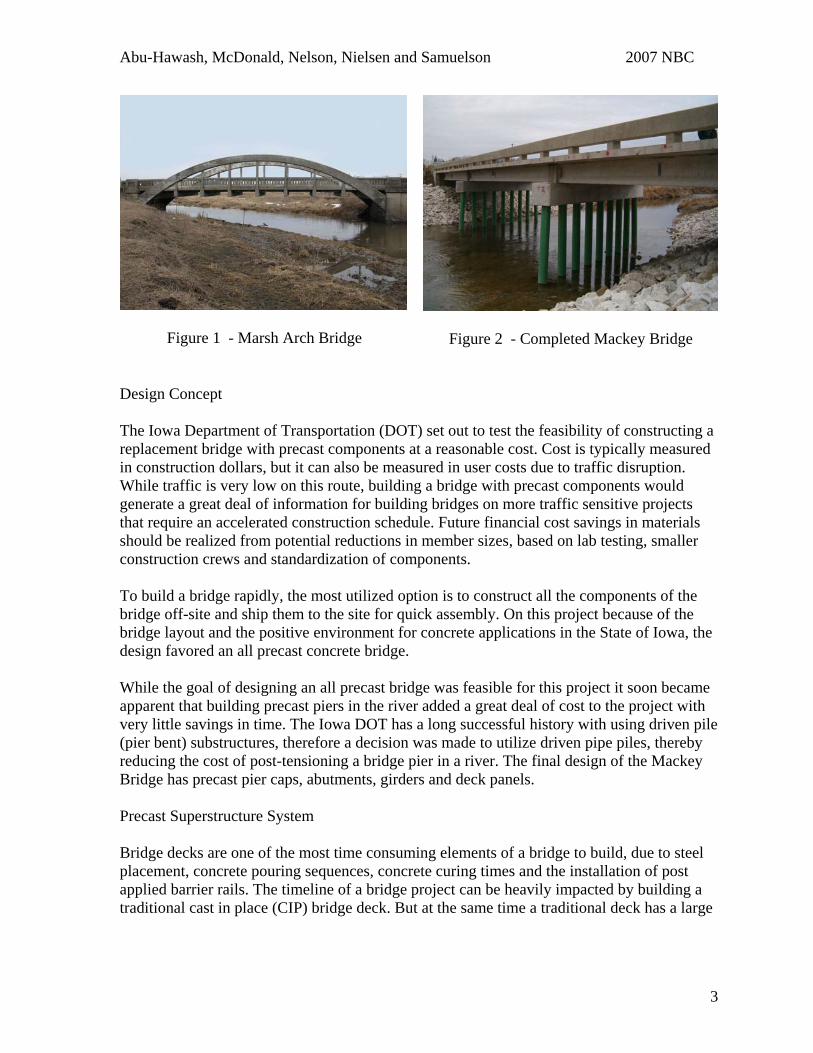
INTRODUCTION Accelerated construction through the use of prefabricated components is a proven methodology used to reduce traffic congestion and road user costs, without sacrificing the quality of the finished product. The Innovative Bridge Research and Construction (IBRC) program gave Iowa the opportunity to demonstrate construction acceleration on two projects, the Mackey Bridge in Boone and the Madison County Bridge. Success achieved on these projects will pave the way for future implementation of accelerated construction in Iowa. At the time the IBRC project was authorized, it was decided that the Iowa Department of Transportation would design and let the projects, the counties would perform the inspection of the bridge construction, and Iowa State University would test bridge components and document the construction process. A roundtable meeting was held between the designers and representatives from the Iowa Precast Concrete Association to determine what types of precast concrete systems were available and best suited this application. A list of possible superstructure and substructure elements was comprised. In February of 2005, a one-day Accelerated Construction Technology Transfer (ACTT) “mini” workshop was held at the Center for Transportation Research and Education at Iowa State University with national accelerated construction experts, designers and officials from the Iowa Department of Transportation, county engineers, university professors and researchers, and representatives from the precast concrete and construction industries. The group was divided into various skill sets on various topics. The end product of the “mini” workshop was a rough concept for the replacement bridges. MACKEY BRIDGE Completed in December 2006, the new Mackey Bridge replaced a Marsh Rainbow Arch Bridge located on 120th Street, over Squaw Creek, in Boone County, Iowa (See Figure 1). The Marsh Arch was built in 1917 and featured a single 76-foot long span with an 18 foot wide roadway. The new Bridge has three spans, two 47’-5 end spans, and a 56’-6 center span, with a 30 degree right ahead skew. It was built with integral abutments, two fixed piers, a precast deck situated on four precast girders, and measures 151’-4 feet long with a 30’-6 foot wide roadway (See Figure 2). A typical three span replacement bridge was chosen to keep the piers out of the center of the channel, and to broaden the research goals to include information on precast panels over piers.
2
Abu-Hawash, McDonald, Nelson, Nielsen and Samuelson 2007 NBC
Figure 1 - Marsh Arch Bridge
Figure 2 - Completed Mackey Bridge
Design Concept The Iowa Department of Transportation (DOT) set out to test the feasibility of constructing a replacement bridge with precast components at a reasonable cost. Cost is typically measured in construction dollars, but it can also be measured in user costs due to traffic disruption. While traffic is very low on this route, building a bridge with precast components would generate a great deal of information for building bridges on more traffic sensitive projects that require an accelerated construction schedule. Future financial cost savings in materials should be realized from potential reductions in member sizes, based on lab testing, smaller construction crews and standardization of components. To build a bridge rapidly, the most utilized option is to construct all the components of the bridge off-site and ship them to the site for quick assembly. On this project because of the bridge layout and the positive environment for concrete applications in the State of Iowa, the design favored an all precast concrete bridge. While the goal of designing an all precast bridge was feasible for this project it soon became apparent that building precast piers in the river added a great deal of cost to the project with very little savings in time. The Iowa DOT has a long successful history with using driven pile (pier bent) substructures, therefore a decision was made to utilize driven pipe piles, thereby reducing the cost of post-tensioning a bridge pier in a river. The final design of the Mackey Bridge has precast pier caps, abutments, girders and deck panels. Precast Superstructure System Bridge decks are one of the most time consuming elements of a bridge to build, due to steel placement, concrete pouring sequences, concrete curing times and the installation of post applied barrier rails. The timeline of a bridge project can be heavily impacted by building a traditional cast in place (CIP) bridge deck. But at the same time a traditional deck has a large
3
Abu-Hawash, McDonald, Nelson, Nielsen and Samuelson 2007 NBC
number of advantages over most precast decks. For example, it is easier to pour a traditional deck full depth, composite with the substructure, allow for tension over the piers, and incorporate continuity for loadings, all of which are difficult to accomplish in a precast deck. Precast decks have their advantages too, with the largest being their ability to accelerate the on site construction of a project. Other advantages include, uniform factory quality, higher concrete strengths, and a reduction in the number of personnel required at a bridge site to construct the deck. The Mackey Bridge precast deck panels looked to combine elements of the traditional cast in place deck with precast panels, using the model of the NUDECK1 precast panels as a starting point. The Iowa DOT strove to design a flexible full depth precast deck system. The NUDECK precast deck system was developed by the University of Nebraska-Lincoln and tested by Nebraska Department of Roads on the Skyline Bridge in Nebraska. The two span Skyline Bridge utilized a 150 mm (6 inch) thick, full roadway width panel, placed on steel girders, with a post-applied 50 mm (2 inch) overlay,. One of the attractive qualities of the NUDECK was the connection between the precast panels and the supporting girders through the use of longitudinal closure joints. This joint is intended to better unify the composite action of the girder and precast deck panel. NUDECK panels used on the Skyline Bridge spanned the entire width of the bridge, with the roadway crown developed in each panel by cutting a number of top strands and shaping the crown on a saddle. With the goal of assembling a bridge onsite as close to the final in place state as possible, the Iowa DOT wanted to utilize full-depth deck panels instead of a two stage process that utilized an overlay. In addition, the Iowa DOT wanted a deck system that could be used on a number of different bridge layouts, including staged construction projects. The Mackey Bridge panels were designed as two side by side panels with a center closure joint that was cast on site. The closure joint allowed for smaller more easily fabricated flat panels without the need to “break” the panels to form a roadway crown. The closure joint would form the roadway crown. The two panel system would allow staged construction. Other advantages of smaller, panels include the ability of a large number of precast manufacturers to produce the panels, lower loss costs if a panel was damaged, and smaller equipment required for handling the panels. The deck panels are supported by standard pre-tensioned precast beams that are placed on 8’-4 centerlines with a post applied cast-in-place post and beam barrier rail. The barrier rail system used is a county standard and future applications of this system may consider precast barrier rails (See Figure 3).
4
Abu-Hawash, McDonald, Nelson, Nielsen and Samuelson 2007 NBC
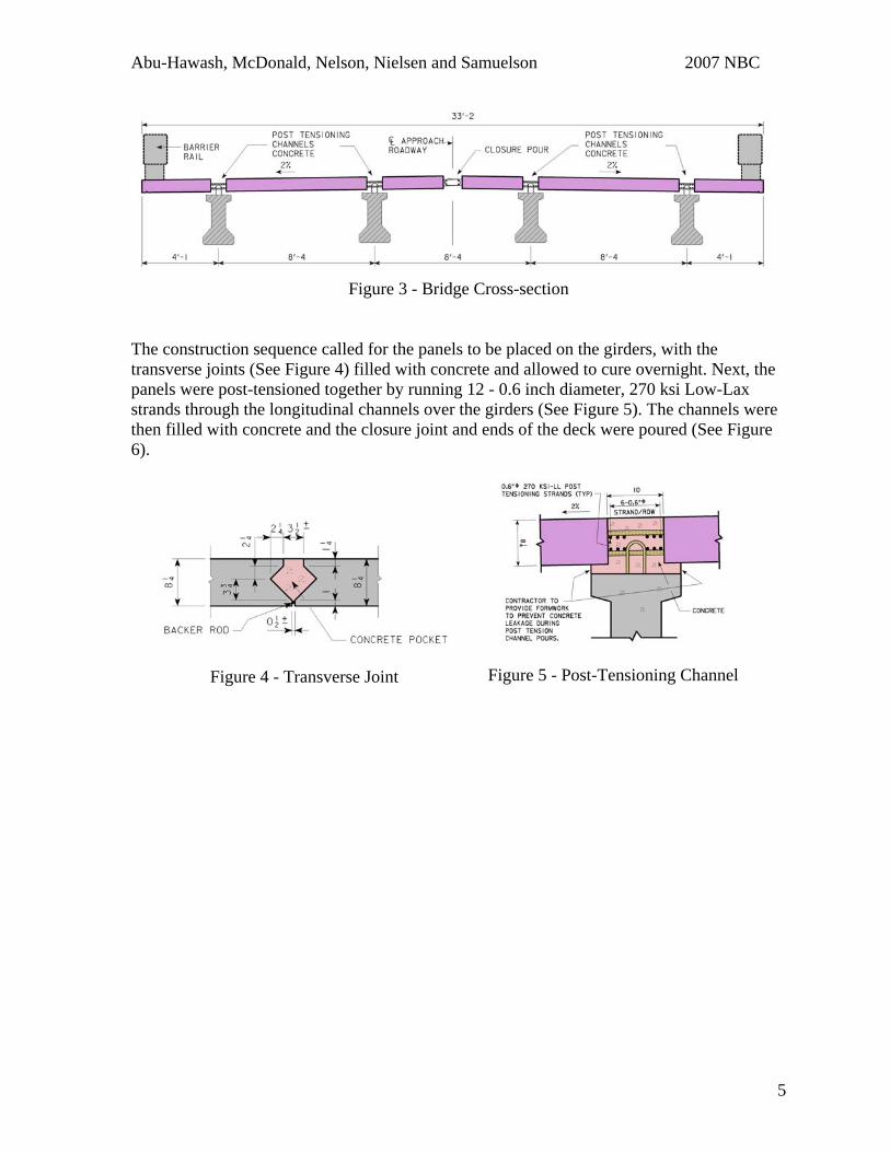
Figure 3 - Bridge Cross-section
The construction sequence called for the panels to be placed on the girders, with the transverse joints (See Figure 4) filled with concrete and allowed to cure overnight. Next, the panels were post-tensioned together by running 12 - 0.6 inch diameter, 270 ksi Low-Lax strands through the longitudinal channels over the girders (See Figure 5). The channels were then filled with concrete and the closure joint and ends of the deck were poured (See Figure 6).
Figure 4 - Transverse Joint
Figure 5 - Post-Tensioning Channel
5
Abu-Hawash, McDonald, Nelson, Nielsen and Samuelson 2007 NBC
Figure 6 - Deck Panel Layout
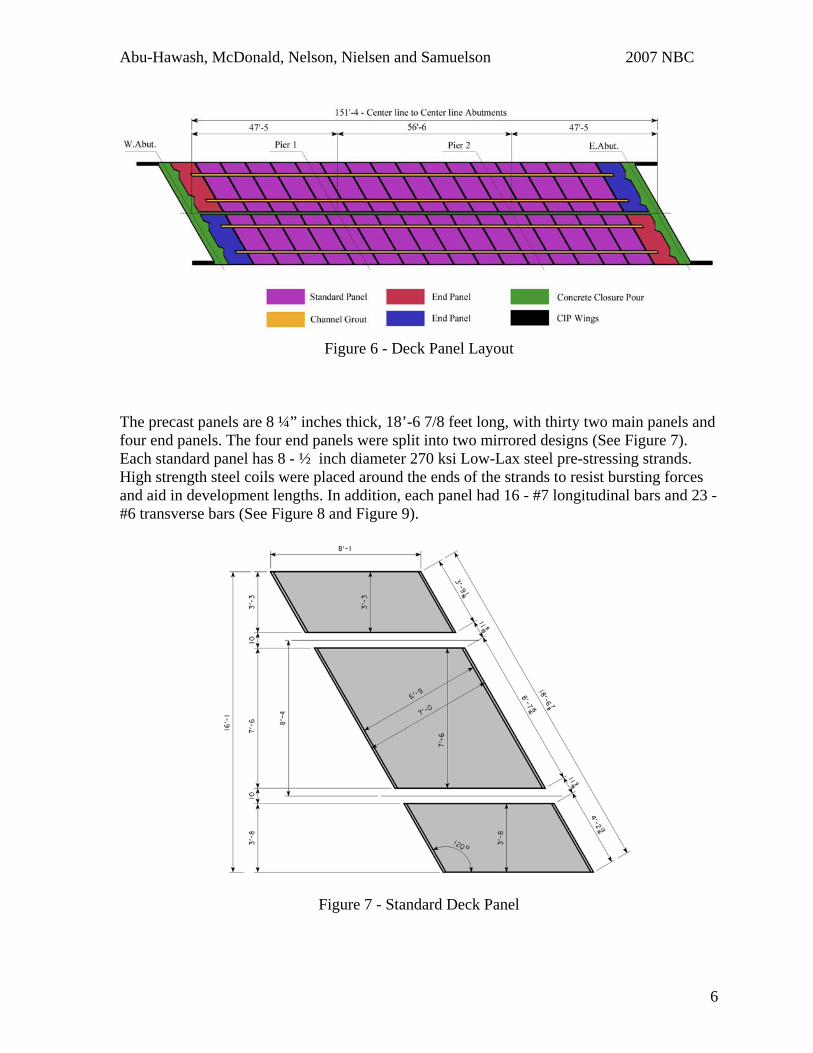
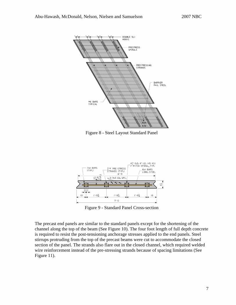
The precast panels are 8 ¼” inches thick, 18’-6 7/8 feet long, with thirty two main panels and four end panels. The four end panels were split into two mirrored designs (See Figure 7). Each standard panel has 8 - ½ inch diameter 270 ksi Low-Lax steel pre-stressing strands. High strength steel coils were placed around the ends of the strands to resist bursting forces and aid in development lengths. In addition, each panel had 16 - #7 longitudinal bars and 23 - #6 transverse bars (See Figure 8 and Figure 9).
Figure 7 - Standard Deck Panel
6
Abu-Hawash, McDonald, Nelson, Nielsen and Samuelson 2007 NBC
Figure 8 - Steel Layout Standard Panel
Figure 9 - Standard Panel Cross-section
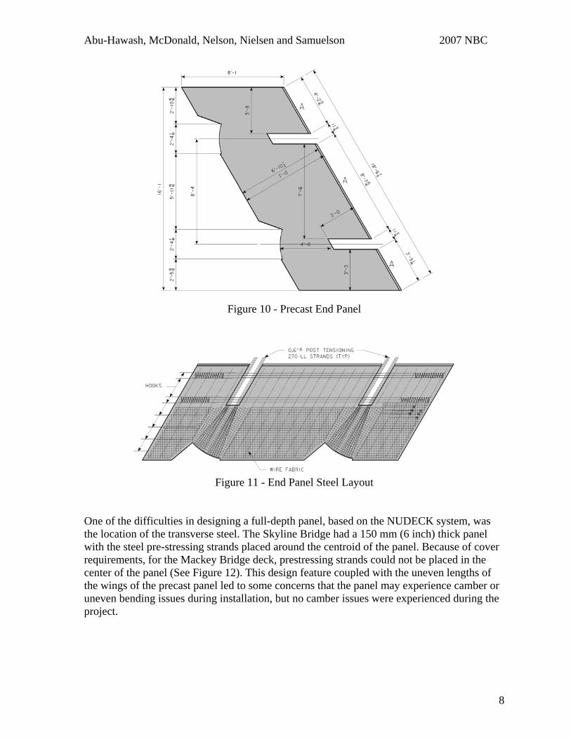
The precast end panels are similar to the standard panels except for the shortening of the channel along the top of the beam (See Figure 10). The four foot length of full depth concrete is required to resist the post-tensioning anchorage stresses applied to the end panels. Steel stirrups protruding from the top of the precast beams were cut to accommodate the closed section of the panel. The strands also flare out in the closed channel, which required welded wire reinforcement instead of the pre-stressing strands because of spacing limitations (See Figure 11).
7
Abu-Hawash, McDonald, Nelson, Nielsen and Samuelson 2007 NBC
Figure 10 - Precast End Panel
Figure 11 - End Panel Steel Layout
One of the difficulties in designing a full-depth panel, based on the NUDECK system, was the location of the transverse steel. The Skyline Bridge had a 150 mm (6 inch) thick panel with the steel pre-stressing strands placed around the centroid of the panel. Because of cover requirements, for the Mackey Bridge deck, prestressing strands could not be placed in the center of the panel (See Figure 12). This design feature coupled with the uneven lengths of the wings of the precast panel led to some concerns that the panel may experience camber or uneven bending issues during installation, but no camber issues were experienced during the project.
8
Abu-Hawash, McDonald, Nelson, Nielsen and Samuelson 2007 NBC
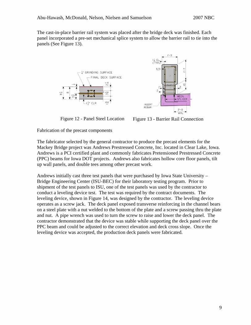
The cast-in-place barrier rail system was placed after the bridge deck was finished. Each panel incorporated a pre-set mechanical splice system to allow the barrier rail to tie into the panels (See Figure 13).
Figure 12 - Panel Steel Location
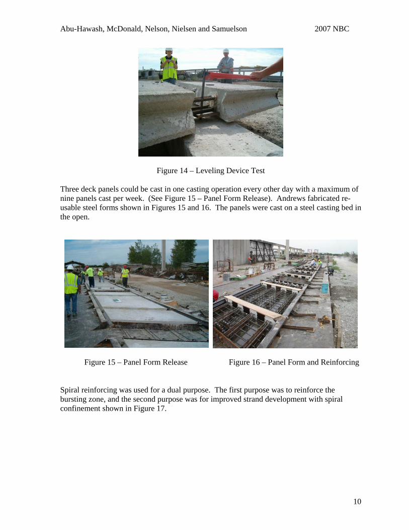
Figure 13 - Barrier Rail Connection Fabrication of the precast components The fabricator selected by the general contractor to produce the precast elements for the Mackey Bridge project was Andrews Prestressed Concrete, Inc. located in Clear Lake, Iowa. Andrews is a PCI certified plant and commonly fabricates Pretensioned Prestressed Concrete (PPC) beams for Iowa DOT projects. Andrews also fabricates hollow core floor panels, tilt up wall panels, and double tees among other precast work. Andrews initially cast three test panels that were purchased by Iowa State University – Bridge Engineering Center (ISU-BEC) for their laboratory testing program. Prior to shipment of the test panels to ISU, one of the test panels was used by the contractor to conduct a leveling device test. The test was required by the contract documents. The leveling device, shown in Figure 14, was designed by the contractor. The leveling device operates as a screw jack. The deck panel exposed transverse reinforcing in the channel bears on a steel plate with a nut welded to the bottom of the plate and a screw passing thru the plate and nut. A pipe wrench was used to turn the screw to raise and lower the deck panel. The contractor demonstrated that the device was stable while supporting the deck panel over the PPC beam and could be adjusted to the correct elevation and deck cross slope. Once the leveling device was accepted, the production deck panels were fabricated.
9
Abu-Hawash, McDonald, Nelson, Nielsen and Samuelson 2007 NBC
Figure 14 – Leveling Device Test Three deck panels could be cast in one casting operation every other day with a maximum of nine panels cast per week. (See Figure 15 – Panel Form Release). Andrews fabricated re-usable steel forms shown in Figures 15 and 16. The panels were cast on a steel casting bed in the open.
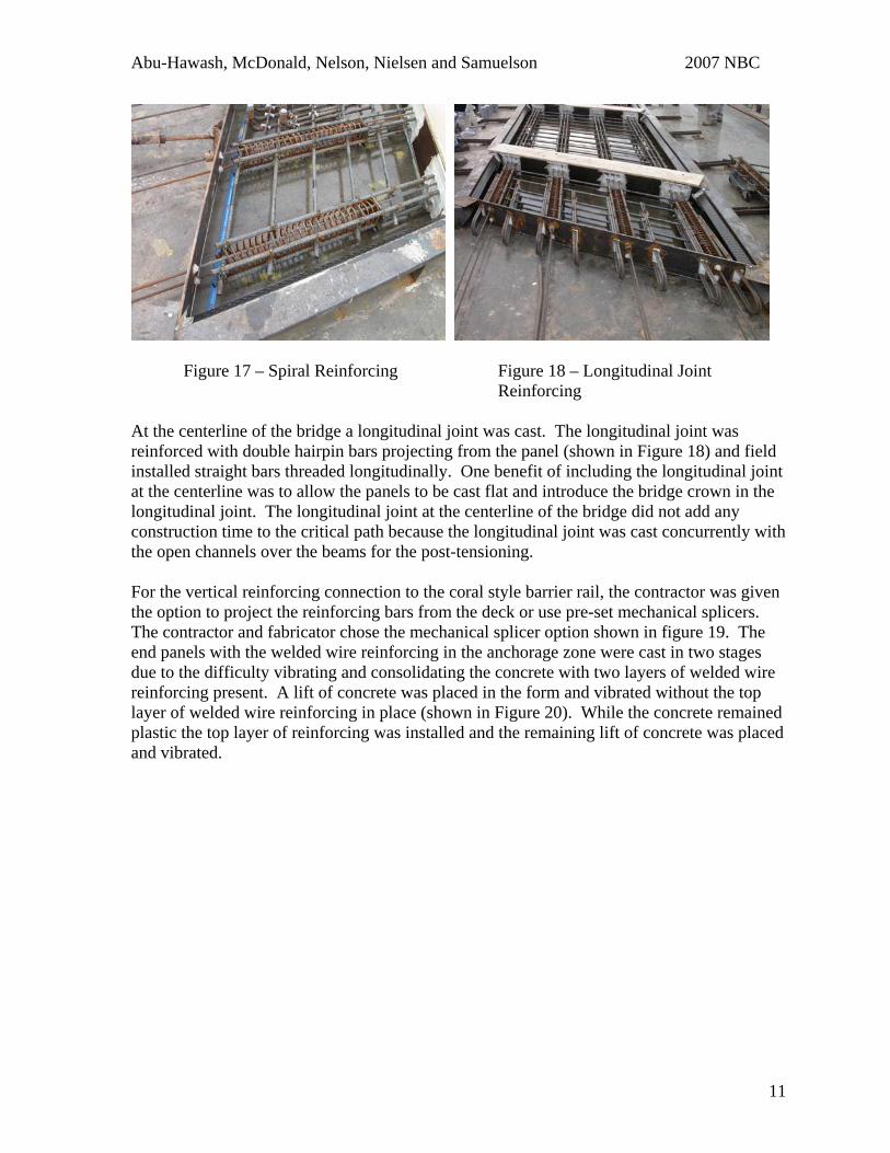
Figure 15 – Panel Form Release Figure 16 – Panel Form and Reinforcing Spiral reinforcing was used for a dual purpose. The first purpose was to reinforce the bursting zone, and the second purpose was for improved strand development with spiral confinement shown in Figure 17.
10
Abu-Hawash, McDonald, Nelson, Nielsen and Samuelson 2007 NBC
Figure 17 – Spiral Reinforcing Figure 18 – Longitudinal Joint Reinforcing
At the centerline of the bridge a longitudinal joint was cast. The longitudinal joint was reinforced with double hairpin bars projecting from the panel (shown in Figure 18) and field installed straight bars threaded longitudinally. One benefit of including the longitudinal joint at the centerline was to allow the panels to be cast flat and introduce the bridge crown in the longitudinal joint. The longitudinal joint at the centerline of the bridge did not add any construction time to the critical path because the longitudinal joint was cast concurrently with the open channels over the beams for the post-tensioning.
For the vertical reinforcing connection to the coral style barrier rail, the contractor was given the option to project the reinforcing bars from the deck or use pre-set mechanical splicers. The contractor and fabricator chose the mechanical splicer option shown in figure 19. The end panels with the welded wire reinforcing in the anchorage zone were cast in two stages due to the difficulty vibrating and consolidating the concrete with two layers of welded wire reinforcing present. A lift of concrete was placed in the form and vibrated without the top layer of welded wire reinforcing in place (shown in Figure 20). While the concrete remained plastic the top layer of reinforcing was installed and the remaining lift of concrete was placed and vibrated.
11
Abu-Hawash, McDonald, Nelson, Nielsen and Samuelson 2007 NBC
Figure 19 – Mechanical Splicers Figure 20 – End Panel Bottom Reinforcing Only
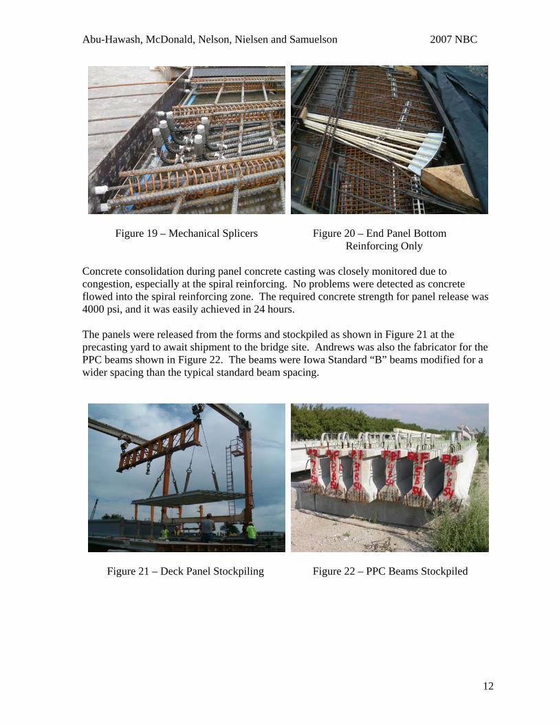
Concrete consolidation during panel concrete casting was closely monitored due to congestion, especially at the spiral reinforcing. No problems were detected as concrete flowed into the spiral reinforcing zone. The required concrete strength for panel release was 4000 psi, and it was easily achieved in 24 hours.
The panels were released from the forms and stockpiled as shown in Figure 21 at the precasting yard to await shipment to the bridge site. Andrews was also the fabricator for the PPC beams shown in Figure 22. The beams were Iowa Standard “B” beams modified for a wider spacing than the typical standard beam spacing.
Figure 21 – Deck Panel Stockpiling Figure 22 – PPC Beams Stockpiled
12
Abu-Hawash, McDonald, Nelson, Nielsen and Samuelson 2007 NBC
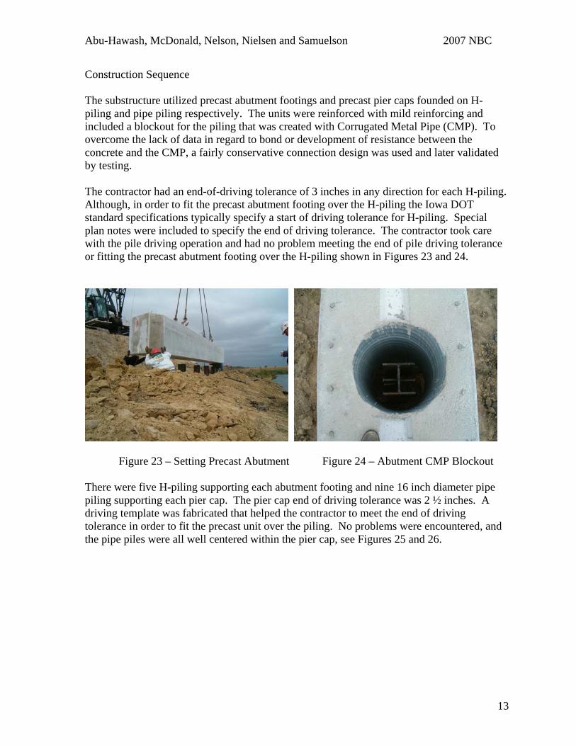
Construction Sequence The substructure utilized precast abutment footings and precast pier caps founded on H-piling and pipe piling respectively. The units were reinforced with mild reinforcing and included a blockout for the piling that was created with Corrugated Metal Pipe (CMP). To overcome the lack of data in regard to bond or development of resistance between the concrete and the CMP, a fairly conservative connection design was used and later validated by testing.
The contractor had an end-of-driving tolerance of 3 inches in any direction for each H-piling. Although, in order to fit the precast abutment footing over the H-piling the Iowa DOT standard specifications typically specify a start of driving tolerance for H-piling. Special plan notes were included to specify the end of driving tolerance. The contractor took care with the pile driving operation and had no problem meeting the end of pile driving tolerance or fitting the precast abutment footing over the H-piling shown in Figures 23 and 24.
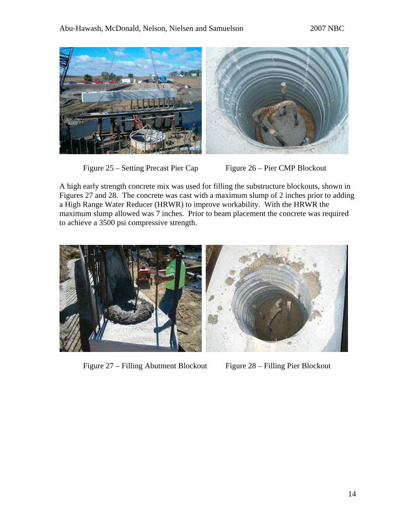
Figure 23 – Setting Precast Abutment Figure 24 – Abutment CMP Blockout There were five H-piling supporting each abutment footing and nine 16 inch diameter pipe piling supporting each pier cap. The pier cap end of driving tolerance was 2 ½ inches. A driving template was fabricated that helped the contractor to meet the end of driving tolerance in order to fit the precast unit over the piling. No problems were encountered, and the pipe piles were all well centered within the pier cap, see Figures 25 and 26.
13
Abu-Hawash, McDonald, Nelson, Nielsen and Samuelson 2007 NBC
Figure 25 – Setting Precast Pier Cap Figure 26 – Pier CMP Blockout A high early strength concrete mix was used for filling the substructure blockouts, shown in Figures 27 and 28. The concrete was cast with a maximum slump of 2 inches prior to adding a High Range Water Reducer (HRWR) to improve workability. With the HRWR the maximum slump allowed was 7 inches. Prior to beam placement the concrete was required to achieve a 3500 psi compressive strength.
Figure 27 – Filling Abutment Blockout Figure 28 – Filling Pier Blockout
14
Abu-Hawash, McDonald, Nelson, Nielsen and Samuelson 2007 NBC
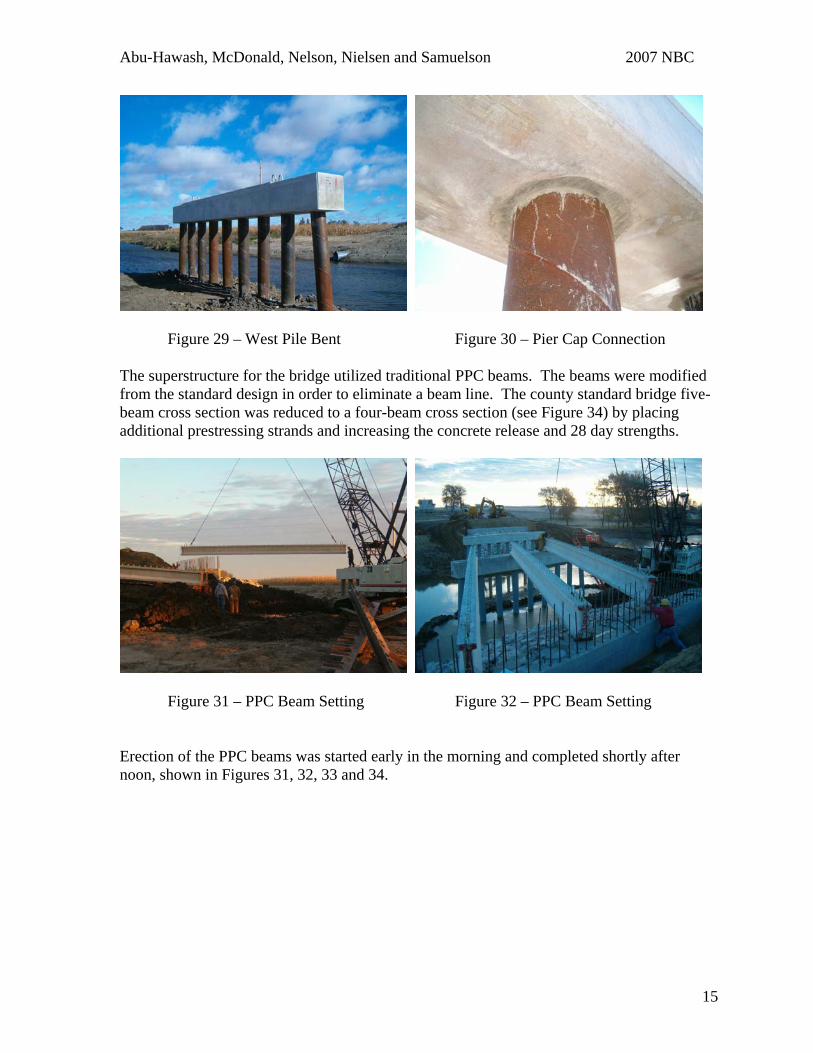
Figure 29 – West Pile Bent Figure 30 – Pier Cap Connection The superstructure for the bridge utilized traditional PPC beams. The beams were modified from the standard design in order to eliminate a beam line. The county standard bridge five-beam cross section was reduced to a four-beam cross section (see Figure 34) by placing additional prestressing strands and increasing the concrete release and 28 day strengths.
Figure 31 – PPC Beam Setting Figure 32 – PPC Beam Setting Erection of the PPC beams was started early in the morning and completed shortly after noon, shown in Figures 31, 32, 33 and 34.
15
Abu-Hawash, McDonald, Nelson, Nielsen and Samuelson 2007 NBC
Figure 33 – PPC Beams Erected Figure 34 – PPC Beams Erected
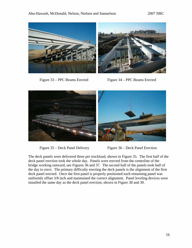
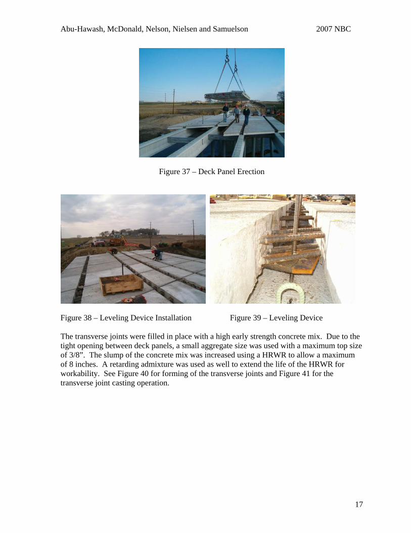
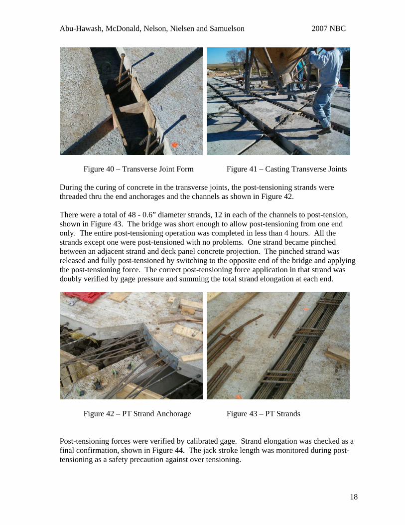
Figure 35 – Deck Panel Delivery Figure 36 – Deck Panel Erection The deck panels were delivered three per truckload, shown in Figure 35. The first half of the deck panel erection took the whole day. Panels were erected from the centerline of the bridge working outward, see Figures 36 and 37. The second half of the panels took half of the day to erect. The primary difficulty erecting the deck panels is the alignment of the first deck panel erected. Once the first panel is properly positioned each remaining panel was uniformly offset 3/8 inch and maintained the correct alignment. Panel leveling devices were installed the same day as the deck panel erection, shown in Figure 38 and 39.
16
Abu-Hawash, McDonald, Nelson, Nielsen and Samuelson 2007 NBC
Figure 37 – Deck Panel Erection
Figure 38 – Leveling Device Installation Figure 39 – Leveling Device The transverse joints were filled in place with a high early strength concrete mix. Due to the tight opening between deck panels, a small aggregate size was used with a maximum top size of 3/8”. The slump of the concrete mix was increased using a HRWR to allow a maximum of 8 inches. A retarding admixture was used as well to extend the life of the HRWR for workability. See Figure 40 for forming of the transverse joints and Figure 41 for the transverse joint casting operation.
17
Abu-Hawash, McDonald, Nelson, Nielsen and Samuelson 2007 NBC
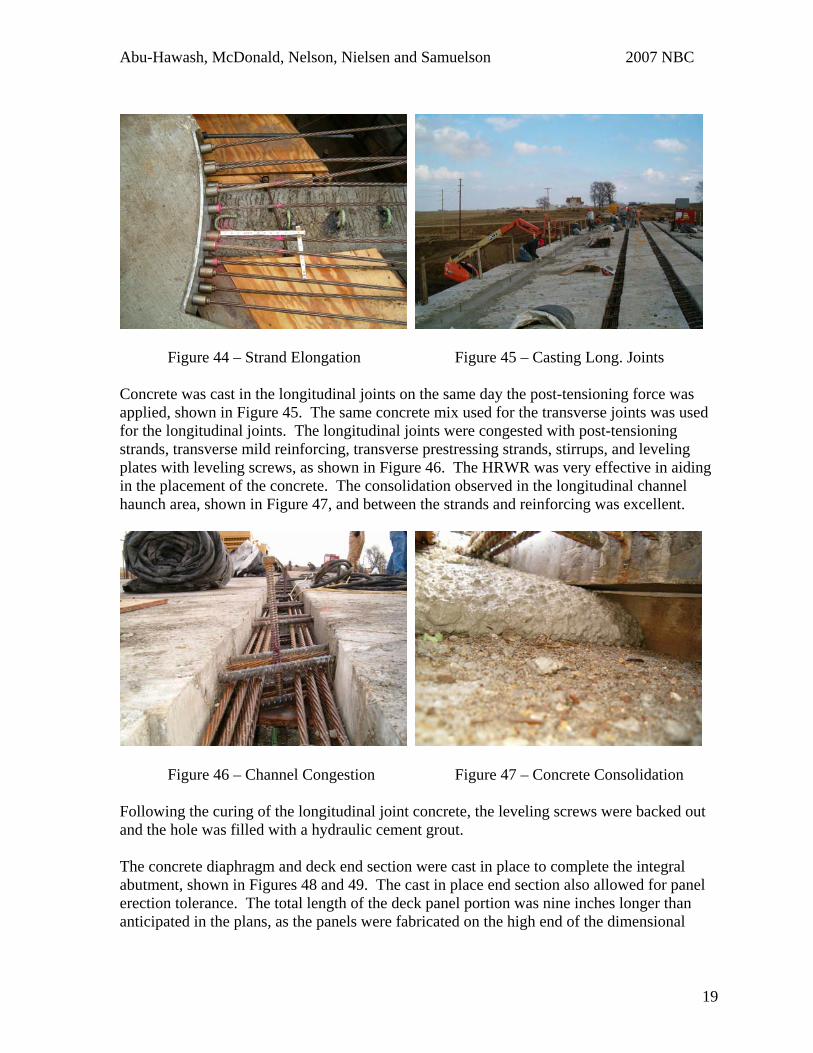
Figure 40 – Transverse Joint Form Figure 41 – Casting Transverse Joints During the curing of concrete in the transverse joints, the post-tensioning strands were threaded thru the end anchorages and the channels as shown in Figure 42.
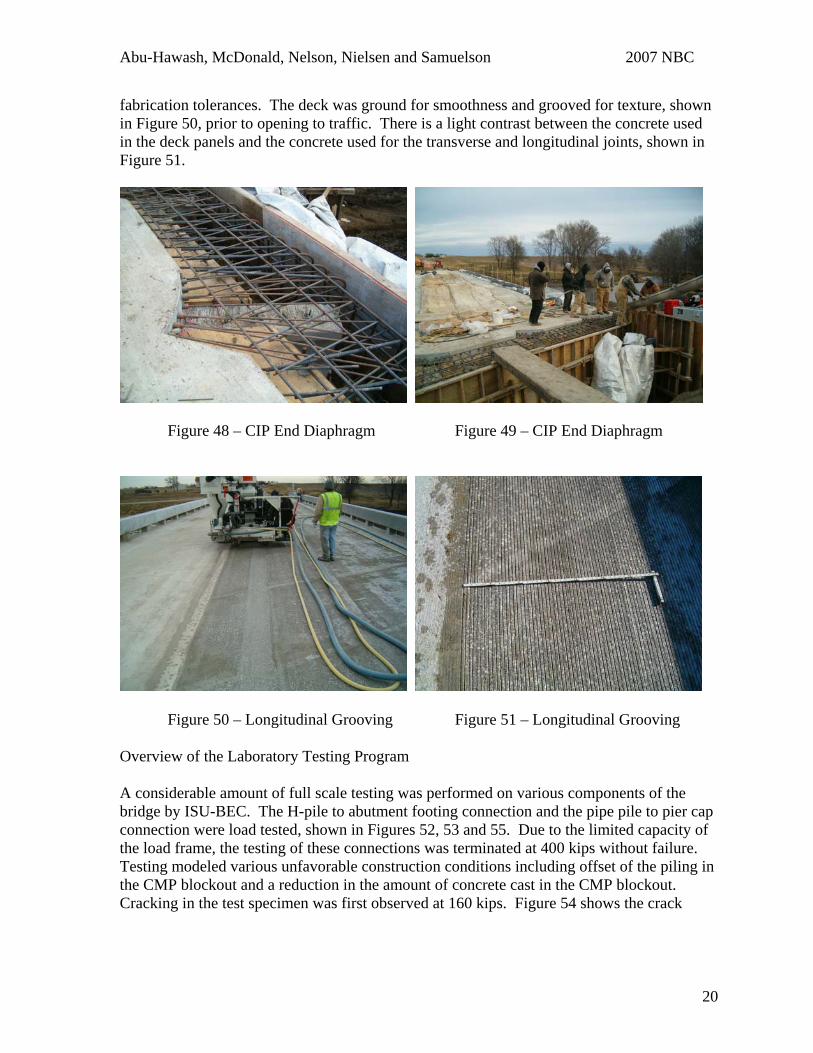
There were a total of 48 - 0.6” diameter strands, 12 in each of the channels to post-tension, shown in Figure 43. The bridge was short enough to allow post-tensioning from one end only. The entire post-tensioning operation was completed in less than 4 hours. All the strands except one were post-tensioned with no problems. One strand became pinched between an adjacent strand and deck panel concrete projection. The pinched strand was released and fully post-tensioned by switching to the opposite end of the bridge and applying the post-tensioning force. The correct post-tensioning force application in that strand was doubly verified by gage pressure and summing the total strand elongation at each end.
Figure 42 – PT Strand Anchorage Figure 43 – PT Strands Post-tensioning forces were verified by calibrated gage. Strand elongation was checked as a final confirmation, shown in Figure 44. The jack stroke length was monitored during post-tensioning as a safety precaution against over tensioning.
18
Abu-Hawash, McDonald, Nelson, Nielsen and Samuelson 2007 NBC
Figure 44 – Strand Elongation Figure 45 – Casting Long. Joints
Concrete was cast in the longitudinal joints on the same day the post-tensioning force was applied, shown in Figure 45. The same concrete mix used for the transverse joints was used for the longitudinal joints. The longitudinal joints were congested with post-tensioning strands, transverse mild reinforcing, transverse prestressing strands, stirrups, and leveling plates with leveling screws, as shown in Figure 46. The HRWR was very effective in aiding in the placement of the concrete. The consolidation observed in the longitudinal channel haunch area, shown in Figure 47, and between the strands and reinforcing was excellent.
Figure 46 – Channel Congestion Figure 47 – Concrete Consolidation Following the curing of the longitudinal joint concrete, the leveling screws were backed out and the hole was filled with a hydraulic cement grout. The concrete diaphragm and deck end section were cast in place to complete the integral abutment, shown in Figures 48 and 49. The cast in place end section also allowed for panel erection tolerance. The total length of the deck panel portion was nine inches longer than anticipated in the plans, as the panels were fabricated on the high end of the dimensional
19
Abu-Hawash, McDonald, Nelson, Nielsen and Samuelson 2007 NBC
fabrication tolerances. The deck was ground for smoothness and grooved for texture, shown in Figure 50, prior to opening to traffic. There is a light contrast between the concrete used in the deck panels and the concrete used for the transverse and longitudinal joints, shown in Figure 51.
Figure 48 – CIP End Diaphragm Figure 49 – CIP End Diaphragm
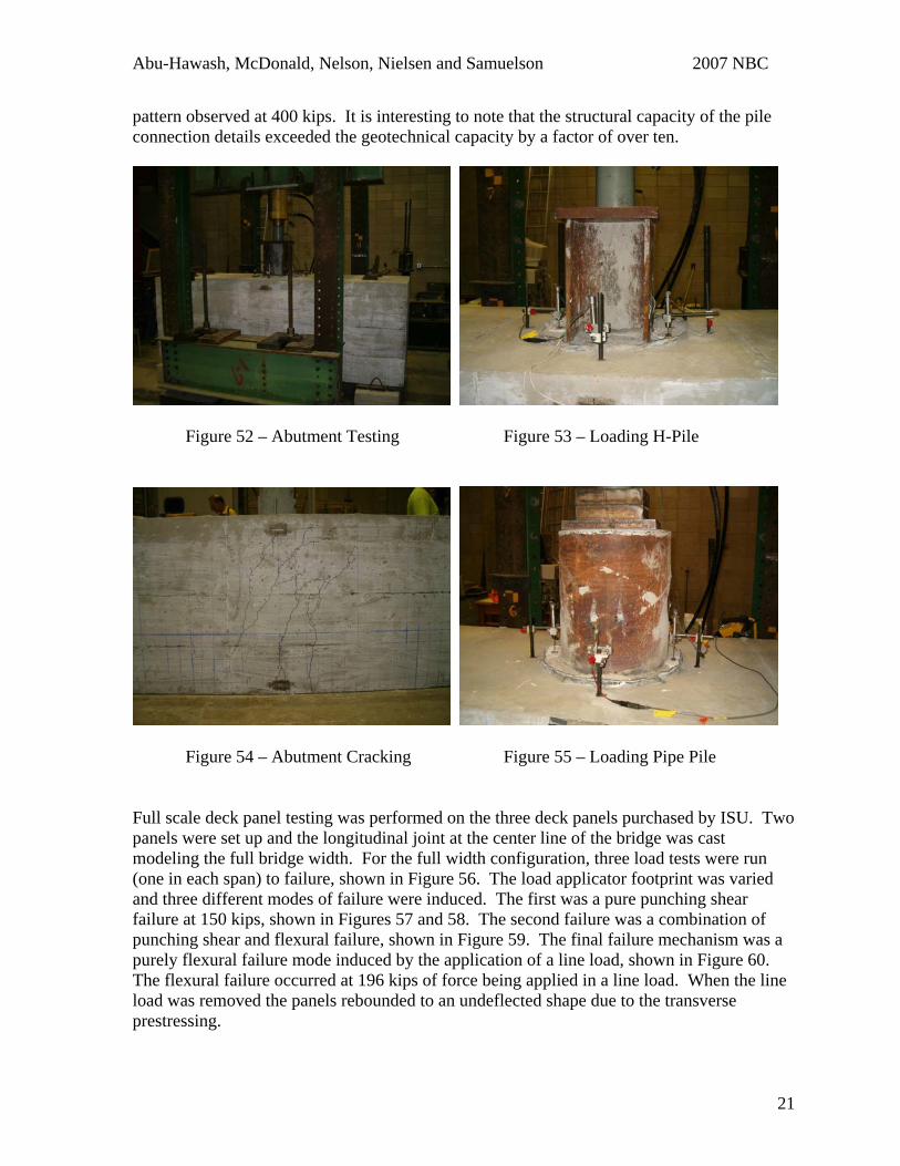
Figure 50 – Longitudinal Grooving Figure 51 – Longitudinal Grooving Overview of the Laboratory Testing Program A considerable amount of full scale testing was performed on various components of the bridge by ISU-BEC. The H-pile to abutment footing connection and the pipe pile to pier cap connection were load tested, shown in Figures 52, 53 and 55. Due to the limited capacity of the load frame, the testing of these connections was terminated at 400 kips without failure. Testing modeled various unfavorable construction conditions including offset of the piling in the CMP blockout and a reduction in the amount of concrete cast in the CMP blockout. Cracking in the test specimen was first observed at 160 kips. Figure 54 shows the crack
20
Abu-Hawash, McDonald, Nelson, Nielsen and Samuelson 2007 NBC
pattern observed at 400 kips. It is interesting to note that the structural capacity of the pile connection details exceeded the geotechnical capacity by a factor of over ten.
Figure 52 – Abutment Testing Figure 53 – Loading H-Pile
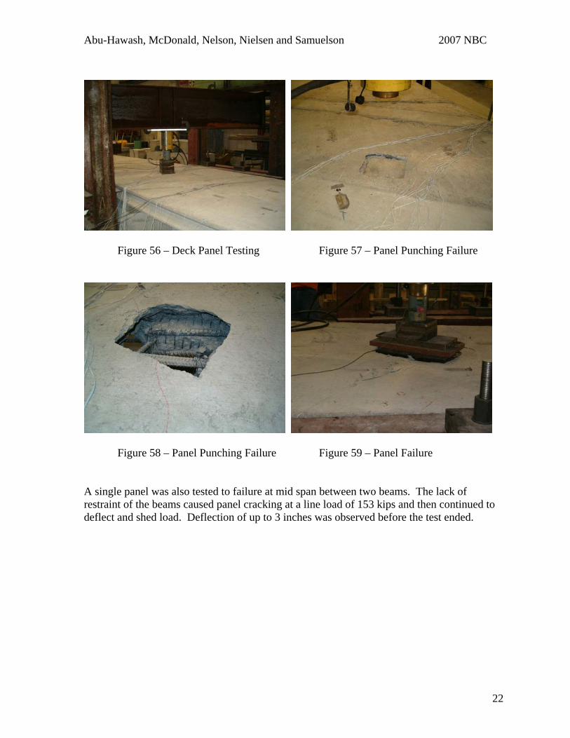
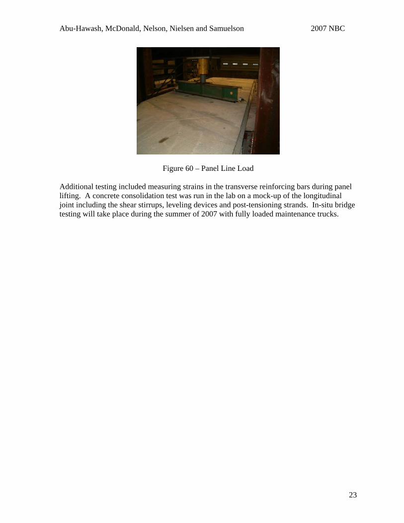
Figure 54 – Abutment Cracking Figure 55 – Loading Pipe Pile Full scale deck panel testing was performed on the three deck panels purchased by ISU. Two panels were set up and the longitudinal joint at the center line of the bridge was cast modeling the full bridge width. For the full width configuration, three load tests were run (one in each span) to failure, shown in Figure 56. The load applicator footprint was varied and three different modes of failure were induced. The first was a pure punching shear failure at 150 kips, shown in Figures 57 and 58. The second failure was a combination of punching shear and flexural failure, shown in Figure 59. The final failure mechanism was a purely flexural failure mode induced by the application of a line load, shown in Figure 60. The flexural failure occurred at 196 kips of force being applied in a line load. When the line load was removed the panels rebounded to an undeflected shape due to the transverse prestressing.
21
Abu-Hawash, McDonald, Nelson, Nielsen and Samuelson 2007 NBC
Figure 56 – Deck Panel Testing Figure 57 – Panel Punching Failure
Figure 58 – Panel Punching Failure Figure 59 – Panel Failure A single panel was also tested to failure at mid span between two beams. The lack of restraint of the beams caused panel cracking at a line load of 153 kips and then continued to deflect and shed load. Deflection of up to 3 inches was observed before the test ended.
22
Abu-Hawash, McDonald, Nelson, Nielsen and Samuelson 2007 NBC
Figure 60 – Panel Line Load Additional testing included measuring strains in the transverse reinforcing bars during panel lifting. A concrete consolidation test was run in the lab on a mock-up of the longitudinal joint including the shear stirrups, leveling devices and post-tensioning strands. In-situ bridge testing will take place during the summer of 2007 with fully loaded maintenance trucks.
23
Abu-Hawash, McDonald, Nelson, Nielsen and Samuelson 2007 NBC
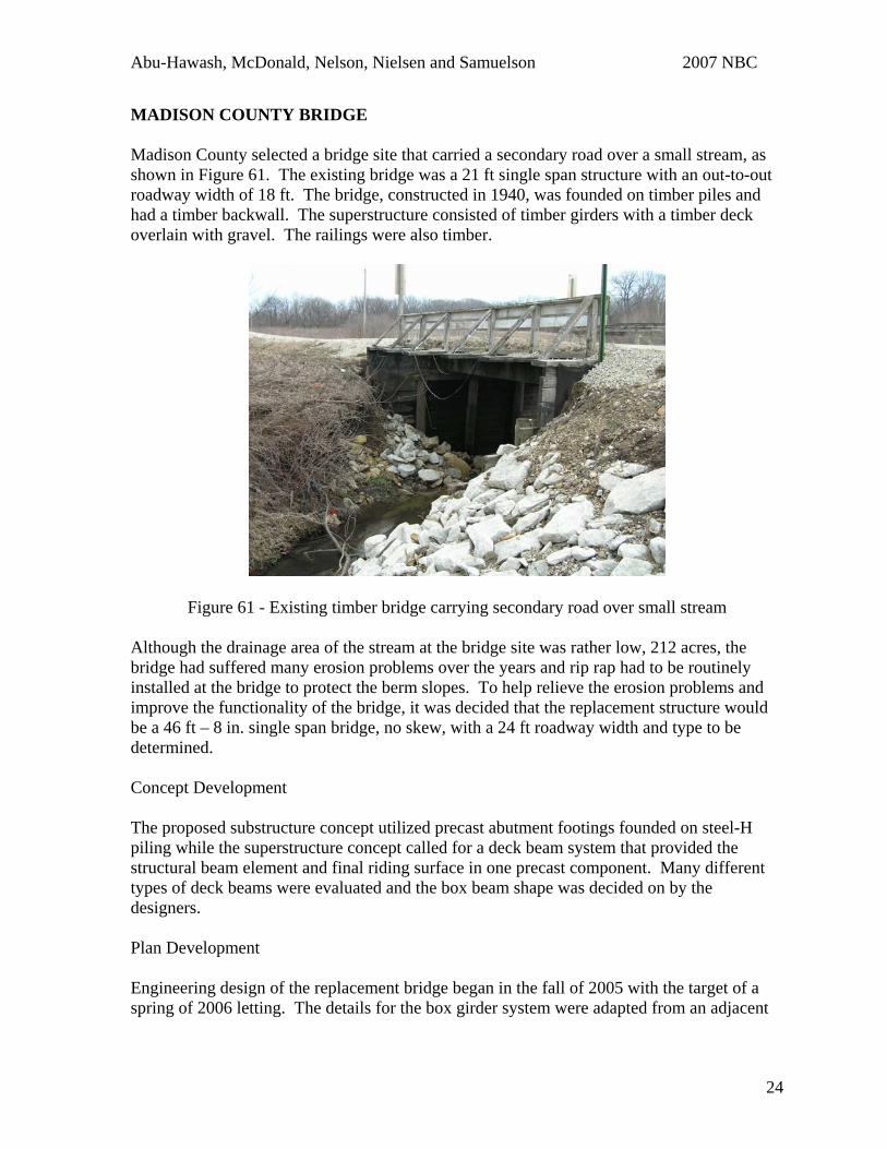
MADISON COUNTY BRIDGE Madison County selected a bridge site that carried a secondary road over a small stream, as shown in Figure 61. The existing bridge was a 21 ft single span structure with an out-to-out roadway width of 18 ft. The bridge, constructed in 1940, was founded on timber piles and had a timber backwall. The superstructure consisted of timber girders with a timber deck overlain with gravel. The railings were also timber.
Figure 61 - Existing timber bridge carrying secondary road over small stream Although the drainage area of the stream at the bridge site was rather low, 212 acres, the bridge had suffered many erosion problems over the years and rip rap had to be routinely installed at the bridge to protect the berm slopes. To help relieve the erosion problems and improve the functionality of the bridge, it was decided that the replacement structure would be a 46 ft – 8 in. single span bridge, no skew, with a 24 ft roadway width and type to be determined. Concept Development The proposed substructure concept utilized precast abutment footings founded on steel-H piling while the superstructure concept called for a deck beam system that provided the structural beam element and final riding surface in one precast component. Many different types of deck beams were evaluated and the box beam shape was decided on by the designers. Plan Development Engineering design of the replacement bridge began in the fall of 2005 with the target of a spring of 2006 letting. The details for the box girder system were adapted from an adjacent
24
Abu-Hawash, McDonald, Nelson, Nielsen and Samuelson 2007 NBC
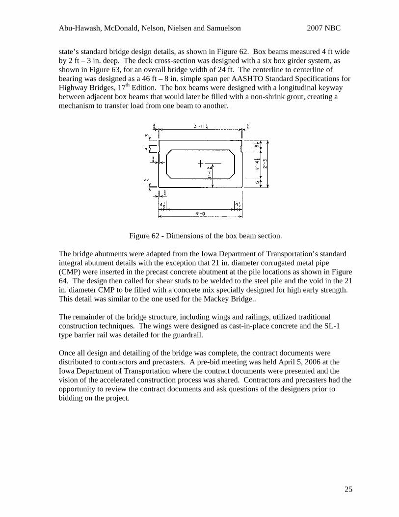
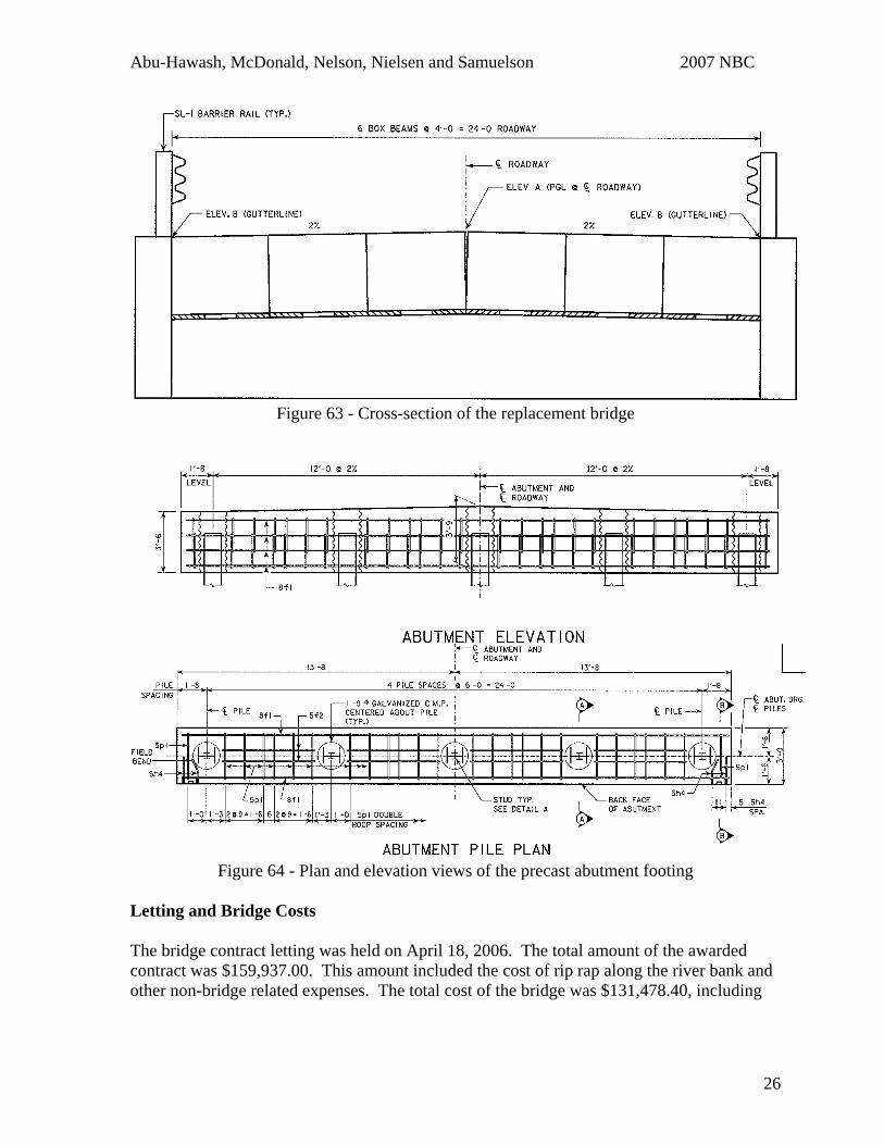
state’s standard bridge design details, as shown in Figure 62. Box beams measured 4 ft wide by 2 ft – 3 in. deep. The deck cross-section was designed with a six box girder system, as shown in Figure 63, for an overall bridge width of 24 ft. The centerline to centerline of bearing was designed as a 46 ft – 8 in. simple span per AASHTO Standard Specifications for Highway Bridges, 17th Edition. The box beams were designed with a longitudinal keyway between adjacent box beams that would later be filled with a non-shrink grout, creating a mechanism to transfer load from one beam to another.
Figure 62 - Dimensions of the box beam section. The bridge abutments were adapted from the Iowa Department of Transportation’s standard integral abutment details with the exception that 21 in. diameter corrugated metal pipe (CMP) were inserted in the precast concrete abutment at the pile locations as shown in Figure 64. The design then called for shear studs to be welded to the steel pile and the void in the 21 in. diameter CMP to be filled with a concrete mix specially designed for high early strength. This detail was similar to the one used for the Mackey Bridge.. The remainder of the bridge structure, including wings and railings, utilized traditional construction techniques. The wings were designed as cast-in-place concrete and the SL-1 type barrier rail was detailed for the guardrail. Once all design and detailing of the bridge was complete, the contract documents were distributed to contractors and precasters. A pre-bid meeting was held April 5, 2006 at the Iowa Department of Transportation where the contract documents were presented and the vision of the accelerated construction process was shared. Contractors and precasters had the opportunity to review the contract documents and ask questions of the designers prior to bidding on the project.
25
Abu-Hawash, McDonald, Nelson, Nielsen and Samuelson 2007 NBC
Figure 63 - Cross-section of the replacement bridge
Figure 64 - Plan and elevation views of the precast abutment footing
Letting and Bridge Costs The bridge contract letting was held on April 18, 2006. The total amount of the awarded contract was $159,937.00. This amount included the cost of rip rap along the river bank and other non-bridge related expenses. The total cost of the bridge was $131,478.40, including
26
Abu-Hawash, McDonald, Nelson, Nielsen and Samuelson 2007 NBC
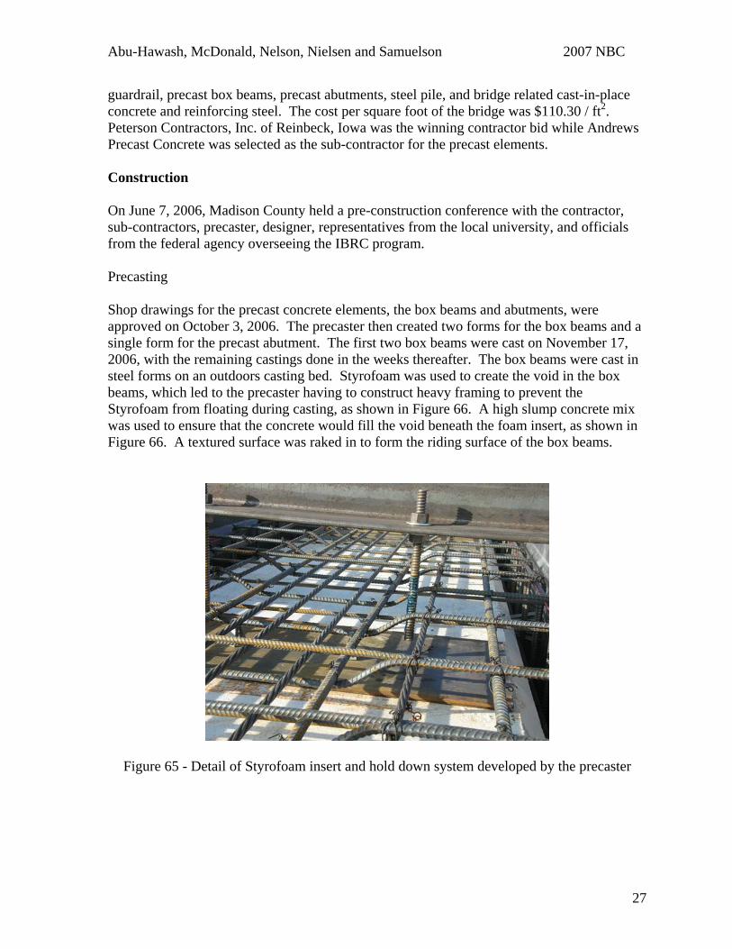
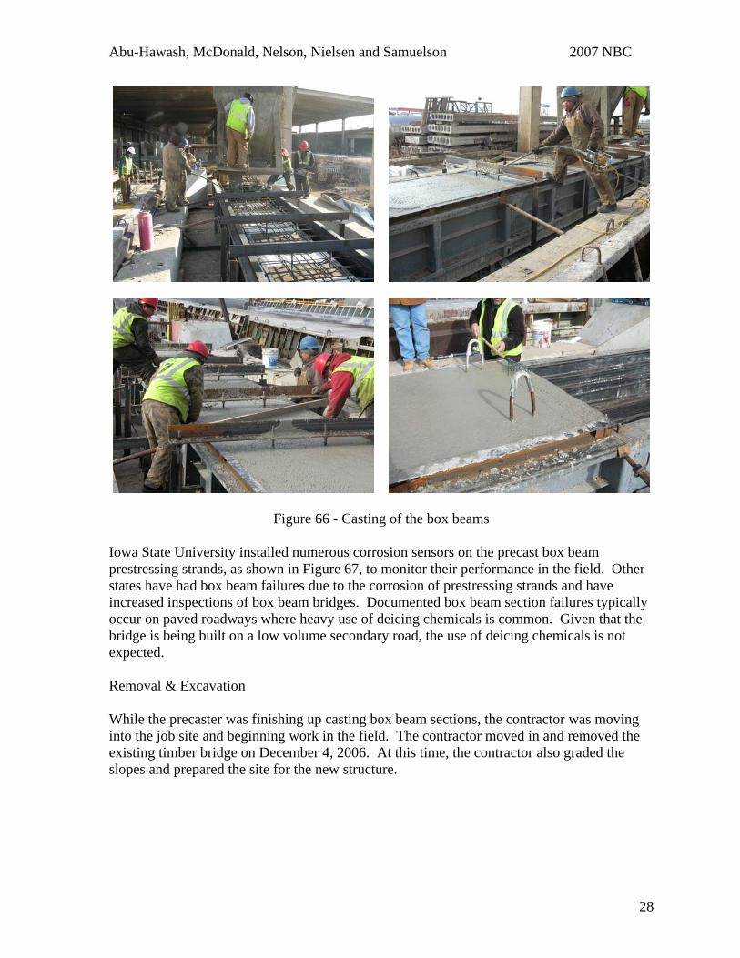
guardrail, precast box beams, precast abutments, steel pile, and bridge related cast-in-place concrete and reinforcing steel. The cost per square foot of the bridge was $110.30 / ft2. Peterson Contractors, Inc. of Reinbeck, Iowa was the winning contractor bid while Andrews Precast Concrete was selected as the sub-contractor for the precast elements. Construction On June 7, 2006, Madison County held a pre-construction conference with the contractor, sub-contractors, precaster, designer, representatives from the local university, and officials from the federal agency overseeing the IBRC program. Precasting Shop drawings for the precast concrete elements, the box beams and abutments, were approved on October 3, 2006. The precaster then created two forms for the box beams and a single form for the precast abutment. The first two box beams were cast on November 17, 2006, with the remaining castings done in the weeks thereafter. The box beams were cast in steel forms on an outdoors casting bed. Styrofoam was used to create the void in the box beams, which led to the precaster having to construct heavy framing to prevent the Styrofoam from floating during casting, as shown in Figure 66. A high slump concrete mix was used to ensure that the concrete would fill the void beneath the foam insert, as shown in Figure 66. A textured surface was raked in to form the riding surface of the box beams.
Figure 65 - Detail of Styrofoam insert and hold down system developed by the precaster
27
Abu-Hawash, McDonald, Nelson, Nielsen and Samuelson 2007 NBC
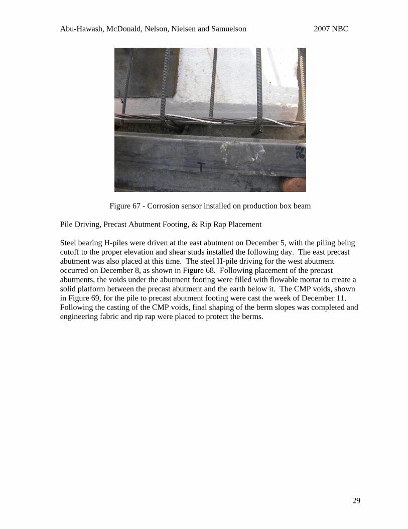
Figure 66 - Casting of the box beams Iowa State University installed numerous corrosion sensors on the precast box beam prestressing strands, as shown in Figure 67, to monitor their performance in the field. Other states have had box beam failures due to the corrosion of prestressing strands and have increased inspections of box beam bridges. Documented box beam section failures typically occur on paved roadways where heavy use of deicing chemicals is common. Given that the bridge is being built on a low volume secondary road, the use of deicing chemicals is not expected. Removal & Excavation While the precaster was finishing up casting box beam sections, the contractor was moving into the job site and beginning work in the field. The contractor moved in and removed the existing timber bridge on December 4, 2006. At this time, the contractor also graded the slopes and prepared the site for the new structure.
28
Abu-Hawash, McDonald, Nelson, Nielsen and Samuelson 2007 NBC
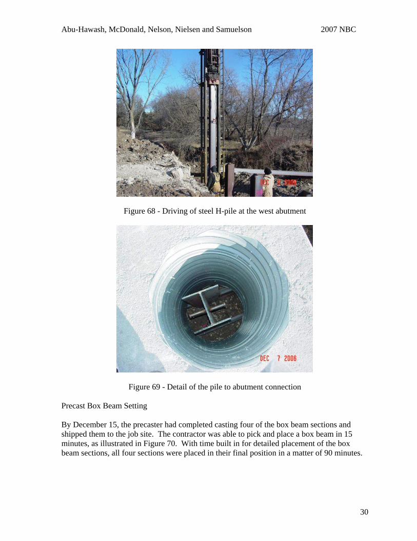
Figure 67 - Corrosion sensor installed on production box beam Pile Driving, Precast Abutment Footing, & Rip Rap Placement Steel bearing H-piles were driven at the east abutment on December 5, with the piling being cutoff to the proper elevation and shear studs installed the following day. The east precast abutment was also placed at this time. The steel H-pile driving for the west abutment occurred on December 8, as shown in Figure 68. Following placement of the precast abutments, the voids under the abutment footing were filled with flowable mortar to create a solid platform between the precast abutment and the earth below it. The CMP voids, shown in Figure 69, for the pile to precast abutment footing were cast the week of December 11. Following the casting of the CMP voids, final shaping of the berm slopes was completed and engineering fabric and rip rap were placed to protect the berms.
29
Abu-Hawash, McDonald, Nelson, Nielsen and Samuelson 2007 NBC
Figure 68 - Driving of steel H-pile at the west abutment
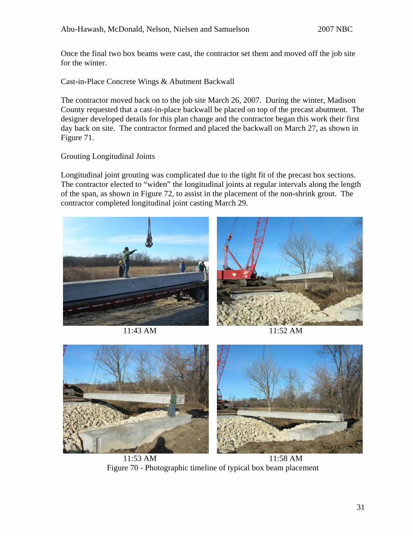
Figure 69 - Detail of the pile to abutment connection Precast Box Beam Setting By December 15, the precaster had completed casting four of the box beam sections and shipped them to the job site. The contractor was able to pick and place a box beam in 15 minutes, as illustrated in Figure 70. With time built in for detailed placement of the box beam sections, all four sections were placed in their final position in a matter of 90 minutes.
30
Abu-Hawash, McDonald, Nelson, Nielsen and Samuelson 2007 NBC
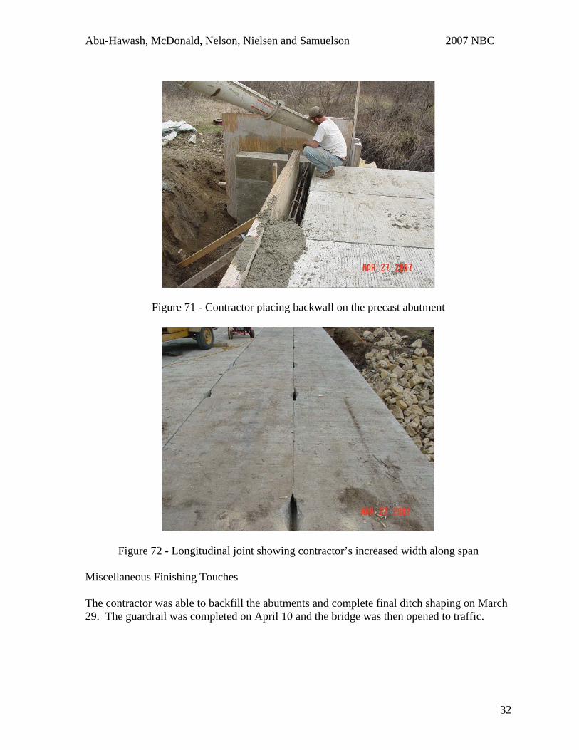
Once the final two box beams were cast, the contractor set them and moved off the job site for the winter. Cast-in-Place Concrete Wings & Abutment Backwall The contractor moved back on to the job site March 26, 2007. During the winter, Madison County requested that a cast-in-place backwall be placed on top of the precast abutment. The designer developed details for this plan change and the contractor began this work their first day back on site. The contractor formed and placed the backwall on March 27, as shown in Figure 71. Grouting Longitudinal Joints Longitudinal joint grouting was complicated due to the tight fit of the precast box sections. The contractor elected to “widen” the longitudinal joints at regular intervals along the length of the span, as shown in Figure 72, to assist in the placement of the non-shrink grout. The contractor completed longitudinal joint casting March 29.
11:43 AM 11:52 AM
11:53 AM 11:58 AM
Figure 70 - Photographic timeline of typical box beam placement
31
Abu-Hawash, McDonald, Nelson, Nielsen and Samuelson 2007 NBC
Figure 71 - Contractor placing backwall on the precast abutment
Figure 72 - Longitudinal joint showing contractor’s increased width along span Miscellaneous Finishing Touches The contractor was able to backfill the abutments and complete final ditch shaping on March 29. The guardrail was completed on April 10 and the bridge was then opened to traffic.
32
Abu-Hawash, McDonald, Nelson, Nielsen and Samuelson 2007 NBC
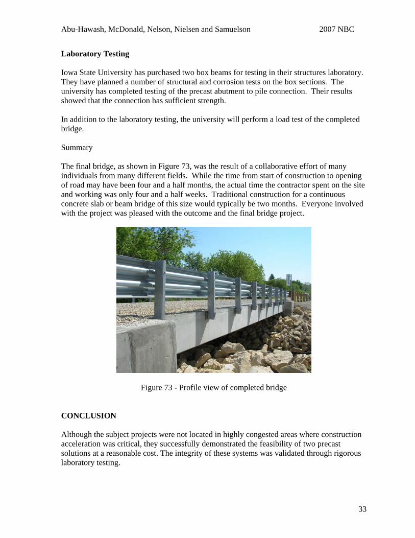
Laboratory Testing Iowa State University has purchased two box beams for testing in their structures laboratory. They have planned a number of structural and corrosion tests on the box sections. The university has completed testing of the precast abutment to pile connection. Their results showed that the connection has sufficient strength. In addition to the laboratory testing, the university will perform a load test of the completed bridge. Summary The final bridge, as shown in Figure 73, was the result of a collaborative effort of many individuals from many different fields. While the time from start of construction to opening of road may have been four and a half months, the actual time the contractor spent on the site and working was only four and a half weeks. Traditional construction for a continuous concrete slab or beam bridge of this size would typically be two months. Everyone involved with the project was pleased with the outcome and the final bridge project.
Figure 73 - Profile view of completed bridge CONCLUSION Although the subject projects were not located in highly congested areas where construction acceleration was critical, they successfully demonstrated the feasibility of two precast solutions at a reasonable cost. The integrity of these systems was validated through rigorous laboratory testing.
33
Abu-Hawash, McDonald, Nelson, Nielsen and Samuelson 2007 NBC
There were many firsts during the planning, design, casting, and construction of these bridges. As with any first, many lessons were learned that will be applied the next time a project similar to this will be undertaken. During the construction of this project, the precast elements came to be on the critical path. This slowed construction and eventually cold winter weather slowed the projects. The Iowa Department of Transportation would suggest on future projects that intermediate completion dates be given in the contract documents for the precast elements. This would ensure that the precast elements are ready for placement when the contractor is ready to place them. Another valuable lesson that came out of this project was that new ways of handling communication between contractor, fabricator, bridge owner, and designers were developed. In an accelerated construction project, construction or fabrication issues must be resolved quickly and efficiently to avoid unneeded delays. Electronic distribution of shop drawings and other means of trimming down transmission of documentation time should be utilized to avoid delays. Lessons learned from these projects have helped Iowa tremendously in implementing construction acceleration on a major project that is currently under design. REFERENCES
1. Fallaha, S., Sun, C., Lafferty, M. D., Tadros, M. K., “High Performance Precast Concrete NUDECK Panel System for Nebraska’s Skyline Bridge,” PCI Journal, V. 49, No. 5, September-October 2004, pp. 40-50.
34