
Accelerated Bridge Construction – On the Fast Track to Success
15
1 Accelerated Bridge Construction – On the Fast Track to Success Rob Burak, P.Eng. Canadian Precast/Prestressed Concrete Institute Rita Seraderian, P.E. Precast/Prestressed Concrete Institute Northeast Region Paper prepared for presentation at the “Bridges – Adjusting to New Realities (A)” Session of the 2010 Annual Conference of the Transportation Association of Canada Halifax, Nova Scotia ABSTRACT Accelerated techniques for bridge construction should be used where the benefits have a positive effect on the construction costs and impacts of the project. At this time, the bridge specific costs on small accelerated construction projects are more than conventional construction, however it is anticipated that costs will come down as more accelerated projects are let. The savings in accelerated construction projects are found in other aspects of the total project such as time, equipment use and labour savings. Decisions to use accelerated bridge construction techniques should be made after considering the following factors: •Temporary Roadways and Bridges •Reductions in Environmental Impacts •User Costs •Political Pressures •Long Detours This paper summarizes the manual Guidelines for Accelerated Bridge Construction Using Precast/Prestressed Concrete Components (1) which was developed in 2006, by the Precast/Prestressed Concrete Institute Northeast’s Bridge Technical Committee. The manual promotes a greater degree of uniformity among owners, engineers and industry with respect to planning, designing, fabricating and constructing prefabricated concrete highway bridges. The manual encompasses the Federal Highway Administration (FHWA) philosophy of accelerated bridge construction (2) and can easily be adopted by Canadian practitioners. Key words: precast, prestressed, concrete, accelerated, bridge construction, fast track
Transcript of Accelerated Bridge Construction – On the Fast Track to Success
1
Accelerated Bridge Construction – On the Fast Track to Success
Rob Burak, P.Eng. Canadian Precast/Prestressed Concrete Institute
Rita Seraderian, P.E. Precast/Prestressed Concrete Institute Northeast Region
Paper prepared for presentation
at the “Bridges – Adjusting to New Realities (A)” Session
of the 2010 Annual Conference of the
Transportation Association of Canada
Halifax, Nova Scotia
ABSTRACT
Accelerated techniques for bridge construction should be used where the benefits have a positive
effect on the construction costs and impacts of the project. At this time, the bridge specific costs
on small accelerated construction projects are more than conventional construction, however it is
anticipated that costs will come down as more accelerated projects are let. The savings in
accelerated construction projects are found in other aspects of the total project such as time,
equipment use and labour savings.
Decisions to use accelerated bridge construction techniques should be made after considering the
following factors:
•Temporary Roadways and Bridges
•Reductions in Environmental Impacts
•User Costs
•Political Pressures
•Long Detours
This paper summarizes the manual Guidelines for Accelerated Bridge Construction Using
Precast/Prestressed Concrete Components (1) which was developed in 2006, by the
Precast/Prestressed Concrete Institute Northeast’s Bridge Technical Committee. The manual
promotes a greater degree of uniformity among owners, engineers and industry with respect to
planning, designing, fabricating and constructing prefabricated concrete highway bridges. The
manual encompasses the Federal Highway Administration (FHWA) philosophy of accelerated
bridge construction (2) and can easily be adopted by Canadian practitioners.
Key words: precast, prestressed, concrete, accelerated, bridge construction, fast track

2
INTRODUCTION
Accelerated construction should always be considered in cases where temporary bridges and
roadways are anticipated. This is especially true where a reasonable detour is available. It may be
desirable to close a roadway completely, build the bridge quickly, and live with a detour. Recent
accelerated construction projects have shown that commuters and businesses prefer a short-term
impact over a significant long-term moderate impact. For bridges over water courses, impacts to
the environment can be lessened by the elimination of a temporary bridge.
Often the need for accelerated construction can be driven by political pressures. The impacts of
construction on commuters and businesses in urban areas can be devastating, and accelerated
construction for bridge construction can be used to limit the time frames for construction projects
in these areas. The cost of construction to highway users is significant. Savings to commuters are
not typically reflected in construction budgets for highway projects; however there is a
significant financial impact to the entire community due to travel delays caused by road closures
or detours. In many cases, the cost of accelerated construction techniques can be offset by
reductions in user costs.
On some projects, the use of staging and temporary bridges is not feasible due to limited right of
way and environmental issues. In these cases detours are the only option. Accelerated
construction techniques should be considered if there are concerns with traffic volumes on
detours and access for emergency vehicles.
Although the intent of the manual Guidelines for Accelerated Bridge Construction Using
Precast/Prestressed Concrete Components is to provide information that applies to
precast/prestressed components used in bridge construction, using these components in non-
prestressed concrete structures is also encouraged. For example, the designer may wish to use a
precast substructure with steel girders and overlay with precast deck panels.
The manual comprises ten sections as follows, and the paper provides an overview of each:
Section 1: Application Overview
Section 2: General Requirements
Section 3: Precast Components
Section 4: Joints
Section 5: Grouting
Section 6: Seismic Conditions
Section 7: Fabrication/Construction
Section 8: Case Study 1, Upton, Maine
Section 9: Case Study 2, Brooksville, Maine
Section 10: Case Study 3, Epping, New Hampshire
The accelerated bridge construction guide is not intended for structural design, rather it is a
resource for structural design engineers and project engineers to use as a tool to accompany
design. Precast concrete materials in Canada must conform to the requirements of CSA A 23.4-
09 Precast Concrete – Materials and Construction (3) and bridge design is in accordance with
CSA-S6-06-Canadian Highway Bridge Design Code (4).

3
SECTION 1: APPLICATION OVERVIEW
The first section of the manual is divided in to five subsections; 1.1 When to Use Accelerated
Construction, 1.2 Rehabilitation Projects, 1.3 Examples of Prefabricated Components, 1.4
Architectural Treatments, and 1.5 Definitions. The first two sections provide a general overview
on considerations to use precast/prestressed accelerated construction techniques either for new
construction or rehabilitation projects. Section 1.3 provides three dimensional renditions that
demonstrate the prefabricated components for typical conditions. Section 1.4 references the
practitioner to sources for architectural guidance such as Chapter 5 of the PCI Bridge Design
Manual (5) and the Minnesota Department of Transportation’s Aesthetic Guidelines for Bridge
Design (6). Precast concrete components lend themselves to adaptable, innovative, and
consistent architectural finishes in a range of designs, colours and textures. These guidelines
may be used to proportion components to fit together to meet the function of the structure as well
as to enhance aesthetics. Section 1.5 provides definitions unique to precast/prestressed concrete
that are beneficial to practitioners, especially those who are being introduced to
precast/prestressed bridge construction methods.

4
Figure 1: The manual provides descriptive diagrams of prefabricated components for several
conditions. The diagrams above show the components for typical substructure and superstructure
construction. Numbers in parentheses indicate the section in the manual where specific guidance
is provided. (Source: PCI).
SECTION 2: GENERAL REQUIREMENTS
Sections 2 through 7 are written in “clause format” with additional commentary provided in a
right hand column on a per clause basis. Section 2 is divided in to five sections; 2.1 Partial
Replacement Projects, 2.2 Design, 2.3 Geometric Configurations, 2.4 Tolerances and 2.5
Shipping and Handling. Section 2.2 describes the design of prefabricated bridges using the same
approach as traditional cast in place concrete structures. Using discrete precast components,
substructures are designed to emulate cast-in-place design and connections between components
are designed to emulate traditional construction joints. The reader is referred to ACI 550.1R-01
Emulating Cast-in-Place Detailing in Precast Concrete Structures (7) for specifications on
emulation design. Canadian practitioners are also directed to CONCISE Beam (8) which is an
easy to use Microsoft Windows based software program for the design of precast concrete beams
to CSA A23.3 or CSA S6, and the CPCI Design Manual Fourth Edition (9).
5
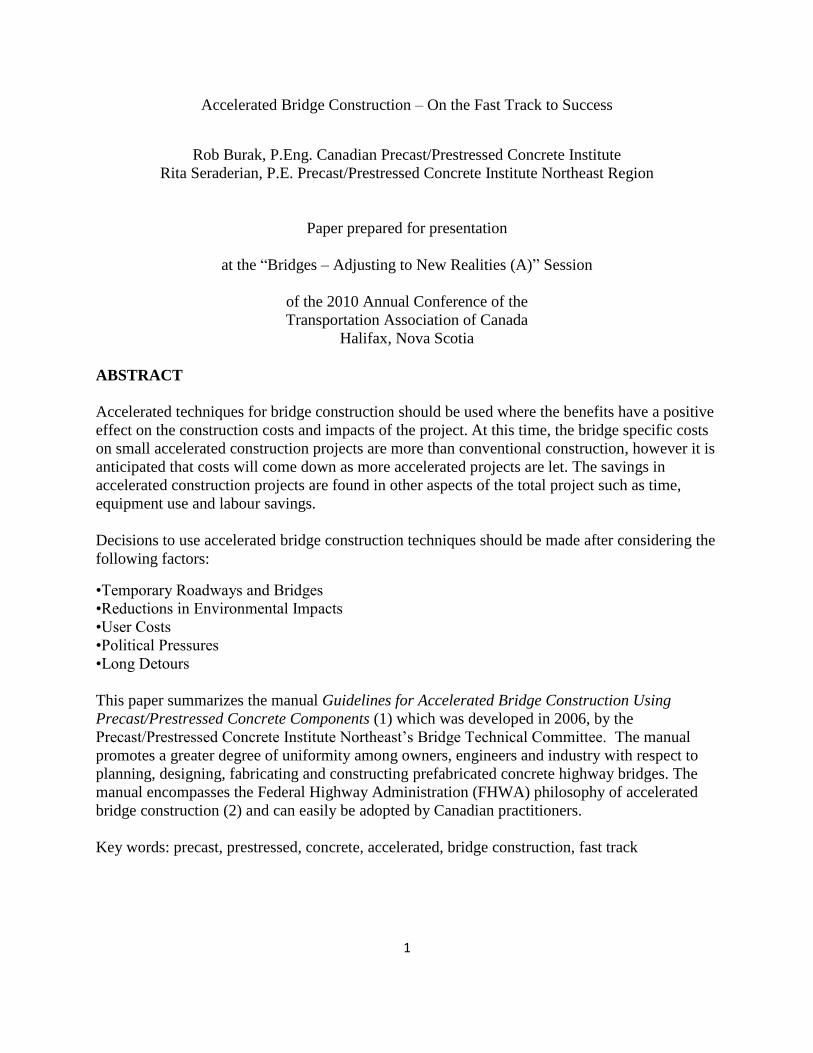
Figure 2: The most common connector is a grouted sleeve. (Source: PCI)
SECTION 3: PRECAST COMPONENTS
This section discusses precast piling, precast substructure components (footings, wall segments,
columns and girder supports), precast superstructure components, proprietary bridge systems,
and precast bridge railings. The designer is referred to PCI Bridge Design Manual BM-02-04
chapter 20 for precast concrete alternatives to steel H piles. Sub-footings of low strength
concrete are required to facilitate load distribution as well as a working platform for the
installation of the precast footings. Levelling screw details and grouting procedures between the
footing and sub-footing via ports that are cast in the footing, are also described. This section
includes many descriptive images as seen in Figures 3 through 12.
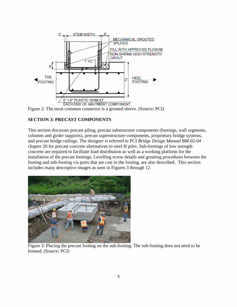
Figure 3: Placing the precast footing on the sub-footing. The sub-footing does not need to be
formed. (Source: PCI)

6
Figure 4: Completed segmental precast footing. (Source: PCI)
Figure 5: Typical details for levelling devices and grouting over a prepared sub-footing or over
cast-in-place supports for uneven conditions. (Source: PCI)
7
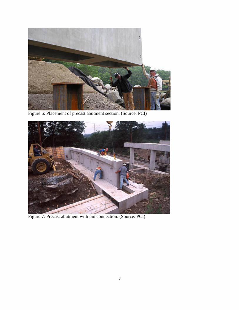
Figure 6: Placement of precast abutment section. (Source: PCI)
Figure 7: Precast abutment with pin connection. (Source: PCI)
8
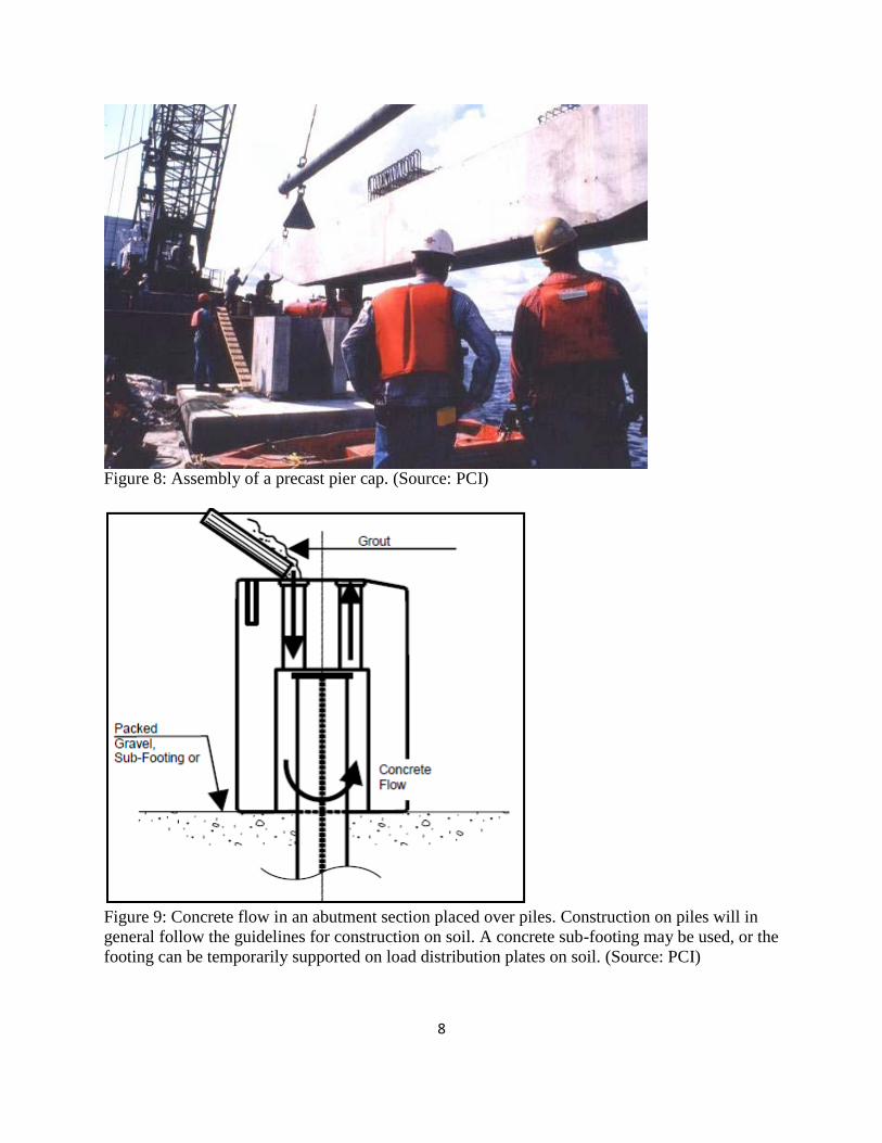
Figure 8: Assembly of a precast pier cap. (Source: PCI)
Figure 9: Concrete flow in an abutment section placed over piles. Construction on piles will in
general follow the guidelines for construction on soil. A concrete sub-footing may be used, or the
footing can be temporarily supported on load distribution plates on soil. (Source: PCI)

9
Figure 10: Completed integral precast abutment section. (Source: PCI)
Figure 11: Schematic of precast deck assembly. (Source: PCI)

10
Figure 12: Placing precast deck slabs. (Source: PCI)
SECTION 4: JOINTS
This section is divided in to 4 subsections; 4.1 General, 4.2 Layout of Joints, 4.3 Structural
Joints, and 4.4 Non structural Joints. In general, the designer should show the proposed layout
plans for all joints that form connections in the structure. This layout plan will be used as a guide
to determine sizes of components and general construction sequencing. Structural joint details
include moment connections for stem joint, cast in place closure pours for horizontal moment
joints, and post tensioning details for complex structures (tall piers), or to eliminate closure pours
for horizontal moment connections (integral abutment stems, pier caps, etc.). Shear connection
details include vertical grouted keys for footing and wall sections. Integral abutment pile
connections are demonstrated by providing a block-out in the precast component, and are
detailed for designs that develop the full moment capacity of the pile.
Figure 13: Typical integral pile details. (Source: PCI)

11
Examples of non-structural joints include retaining wall expansion and contraction joints, joints
between different substructure units (abutment to wing-wall interface), and joints in long pier
bents (where effects of thermal movement can cause large internal frame forces). They are
intended to allow for thermal or differential settlement movement of the adjacent sections of the
structure, and to provide fabrication and construction tolerance. These non structural joints do
not transfer moment, axial or shear forces between adjacent components.
Figure 14: Non structural vertical joint. (Source: PCI)
SECTION 5: GROUTING
This section includes sub sections on sub footings, component to component grouting, pile caps,
post tensioning ducts, and block-outs for anchoring devices. Detailed grouting procedures are
also discussed. An example from the manual for grouting of the stem footing joint shown
previously in figure 2, follows below:
Step 1: Fill the key to just below the lower port of the grouted mechanical splice. The grout
should be installed by pouring the grout into the key from the front face of the vertical
component and moved through the joint to the back-side of the key to promote complete filling
of the joint. This procedure should be started at one end of the joint and proceed continuously
along the joint.
The grout placed in step 1 shall be kept out of the mechanical splice by the use of a washer or
stopper.
Step 2: Grout the mechanical splice.
Step 3: Fill the remainder of the key.

12
SECTION 6: SEISMIC CONSIDERATIONS
The process of designing seismic reinforcement is much the same as for a cast in place concrete
structure, however variations in detailing may be required because of the use of precast
components. These issues are covered in this section. The section includes subsections; 6.1
General Criteria, 6.2 Connections of Superstructure to Substructure (keeper blocks, pilasters,
abutment back wall, anchor rods, integral connections), 6.3 Column Connections (column base
and cap, splices along column length, confinement reinforcement, and 6.4 Footings (internal
reinforcement, pile uplift). The details in this guideline are based on non-staggered mechanical
grouted splices, since the majority of the bridges in the US are in low to moderate seismic zones.
Designers can modify the details in this document to satisfy these requirements for higher
seismic zones and/or Canadian conditions.
SECTION 7: FABRICATION/CONSTRUCTION
This section includes guidance on lifting devices, handling and shipping, assembly plans,
coordination, tolerances during fabrication, inspection, and backfill operations.
The location and design of lifting devices is the responsibility of the precast manufacturer.
Locations that are visually sensitive should be identified on the contract drawings. Lifting
devices should not be used in these areas if possible. Lifting devices in these areas need to be
recessed, easily removed, and patched to match the surrounding concrete. The size of precast
components should be finalized by the precaster and contractor with consideration for shipping
restrictions, equipment availability and site constraints. The final component sizes will be shown
on the assembly plan.
The assembly plan is described as being created by the precaster and contractor and submitted to
the owner for approval. It provides detailed information on the contractor’s means and methods
for assembling the components. The assembly plan should at the very least, include all
information required to complete the work such as:
o Engineer of Record for the assembly plan.
o Shop drawings of all components.
o Specific product names and other material requirements for all grout products proposed
for use.
o Proposed method of erection and the amount and character of equipment required.
o Temporary support requirements for substructures including levelling screws and/or
shims and lateral load and moment resistance requirements for vertical components
during assembly.
o Component assembly sequence.
o Tolerance requirements for the assembly of the components.
o Grouting plan.
Fabrication tolerances are according to standard precast practice. Practitioners should specify
fabrication of precast/prestressed concrete components from certified plants according to CPCI
13
Certification Program for Architectural and Structural Precast Products and Systems (10). The
CPCI certification program is designed to qualify manufacturers who fabricate architectural and
structural precast concrete. The purpose of this audit based program is to provide owners and
designers with the confidence that certified precast concrete manufacturers are qualified to
manufacture the products they supply to the marketplace, are competent to provide quality
precast and have adequate personnel and facilities. The program is governed by an independent
multidisciplinary body and each plant, in addition to having a mandated number of audits
annually, also requires a comprehensive Quality System Manual (QSM). The certification
ensures conformance to the requirements of CSA Standard A23.4, including Appendices A and
B, and the PCI Manuals for Quality Control, MNL-116 and 117 (11).
SECTION 8, 9, AND 10: CASE STUDIES
Case studies are included in the guide for three U.S. projects. Case Study 1 is of the East B Hill
Road in Upton, Maine constructed in 2004. An excerpt from the manual follows:
“This report is a case study on a project under taken by the Maine Department of Transportation
in 2004. In September of 2004 the Maine Department of Transportation completed construction
of the Andover Dam Bridge in Upton, Maine. The design of the bridge consists of a 65-ft single
span, precast, butted box beam superstructure, founded on pile-supported, integral abutments.
The bridge is located on a local road in rural Maine, and the use of a long detour and rapid bridge
construction techniques were determined more cost effective than the use of a temporary bridge.
For this project the use of self consolidating concrete combined with a precast concrete
substructure and superstructure enabled the bridge to be constructed while the road was closed
for a total duration of 96 hours. This case study discusses the background information, specifics
of the new construction, traffic considerations, construction sequence, precast components, and
lessons learned by the Department during the construction of this project.”
Case Study 2 is of the Davis Narrows Bridge in Brooksville, Maine constructed in 2004-2005.
An excerpt from the manual follows:
“The unique features of the existing Bridge, the sensitive environmental habitat, and the tourist
attraction at the Davis Narrows Bridge over the Bagaduce River in Brooksville, Maine created a
set of issues that demanded a fast track approach to bridge design and construction. The Maine
Department of Transportation after considering several options decided to custom design a single
span bridge using all precast elements. The Precast abutments and wingwalls were designed as
post-tensioned units over driven piles to reduce excavation, forming and curing time, and to
eliminate the use of cofferdams. Extensive geotextiles were used to stabilize the causeways and
reduce impacts to Eelgrass patches. The new abutments were installed behind the existing granite
block abutments to avoid changes to hydraulics favored by locals and tourists. Precast Box-
beams were erected efficiently using a launching girder. The entire project from demolition of
the existing bridge to pavement and guardrail installation on the new 89 foot, $1 million Bridge
was completed in only 30 days. The ease with which the bridge was constructed not only
impressed the locals but also the Contractor and the Owner.”

14
Case Study 3 is of the Mill Street Bridge Epping, New Hampshire (12). The Mill Street Bridge
project won two awards in the 2005 PCI Design Awards Program – one for Best Bridge design
for spans between 20 and 41 m and the other for “Best All-Precast Solution”.
CONCLUSION
Many Canadian examples of precast/prestressed bridge construction exist (13) which
demonstrate its capabilities for fast, efficient erection of substructures and superstructures. To
take full advantage of these capabilities requires a consistent approach. The manual Guidelines
for Accelerated Bridge Construction Using Precast/Prestressed Concrete Components
developed in 2006, promotes a greater degree of uniformity among owners, engineers and
industry with respect to planning, designing, fabricating and constructing prefabricated concrete
highway bridges.
REFERENCES
1. PCI 2006. Guidelines for Accelerated Bridge Construction Using Precast/Prestressed
Concrete Components. Precast/Prestressed Concrete Institute North East, Belmont, MA 2. CSA 2009. CSA A23.4-09 Precast Concrete – Materials and Construction, Canadian
Standards Association, Mississauga ON, CAN
3. FHWA Manual – Connection Details for Prefabricated Bridge Elements and Systems
www.fhwa.dot.gov/bridge/prefab/
4. CSA 2006. CSA-S6-06-Canadian Highway Bridge Design Code, Canadian Standards
Association, Mississauga ON, CAN
5. PCI 1997. Bridge Design Manual PCI MNL-133-97. Precast/Prestressed Concrete
Institute, Chicago, IL.
6. Minnesota Department of Transportation’s Aesthetic Guidelines for Bridge Design (5).
7. ACI 2001. Emulating Cast-in-Place Detailing in Precast Concrete Structure ACI
550.1R-01, American Concrete Institute, Farmington Hills, MI ACI 550.1R-01
8. Black Mint Software 2002. CONCISE Beam v4, Black Mint Software Inc., Ottawa ON,
CAN
9. CPCI 2007. Design Manual, Precast Prestressed Concrete, Fourth Edition. Canadian
Precast/Prestressed Concrete Institute (CPCI), Ottawa ON, CAN
10. CPCI 2007. CPCI Certification Program for Architectural and Structural Precast
Products and Systems v1.3 Canadian Precast/Prestressed Concrete Institute (CPCI),
Ottawa ON, CAN
11. PCI, Manual for Quality Control for Plants and Production of Precast and Prestressed
Concrete Products PCI MNL-116. Precast/Prestressed Concrete Institute, Chicago, IL.
12. PCI, 2005. PCI Journal article download, All Precast Substructure Accelerates
Construction of Prestressed Concrete Bridge in New Hampshire
http://www.pci.org/pdf/publications/journal/2005/may-june/jl-05-may-june-4.pdf.
Precast/Prestressed Concrete Institute, Chicago, IL.

15
13. TAC, 2007. Precast Options for Bridge Superstructure Design. Fowler J and Stofko B. Paper prepared for presentation at the Bridges – Economical and Social Linkages Session
2007 Annual Conference of the Transportation Association of Canada, Saskatoon, SK


