Accelerate with FlashSystem V840 Compression Accelerate with IBM FlashSystem V840 Compression Thanks...
92
ibm.com/redbooks Redpaper Front cover Accelerate with IBM FlashSystem V840 Compression Karen Orlando Detlef Helmbrecht James Thompson Effectively implement Real-time Compression in business environments Increase the effective capacity of flash storage Tune and troubleshoot your compression environment
Transcript of Accelerate with FlashSystem V840 Compression Accelerate with IBM FlashSystem V840 Compression Thanks...

ibm.com/redbooks Redpaper
Front cover
Accelerate with IBM FlashSystem V840 Compression
Karen OrlandoDetlef HelmbrechtJames Thompson
Effectively implement Real-time Compression in business environments
Increase the effective capacity of flash storage
Tune and troubleshoot your compression environment


International Technical Support Organization
Accelerate with IBM FlashSystem V840 Compression
February 2015
REDP-5147-00

© Copyright International Business Machines Corporation 2015. All rights reserved.Note to U.S. Government Users Restricted Rights -- Use, duplication or disclosure restricted by GSA ADP ScheduleContract with IBM Corp.
First Edition (February 2015)
This edition applies to FlashSystem V840 Version 1.3, FlashSystem V840 Software Version 7.4
This document was created or updated on February 12, 2015.
Note: Before using this information and the product it supports, read the information in “Notices” on page v.

Contents
Notices . . . . . . . . . . . . . . . . . . . . . . . . . . . . . . . . . . . . . . . . . . . . . . . . . . . . . . . . . . . . . . . . . .vTrademarks . . . . . . . . . . . . . . . . . . . . . . . . . . . . . . . . . . . . . . . . . . . . . . . . . . . . . . . . . . . . . . vi
Preface . . . . . . . . . . . . . . . . . . . . . . . . . . . . . . . . . . . . . . . . . . . . . . . . . . . . . . . . . . . . . . . . . viiAuthors. . . . . . . . . . . . . . . . . . . . . . . . . . . . . . . . . . . . . . . . . . . . . . . . . . . . . . . . . . . . . . . . . . viiNow you can become a published author, too! . . . . . . . . . . . . . . . . . . . . . . . . . . . . . . . . . . viiiComments welcome. . . . . . . . . . . . . . . . . . . . . . . . . . . . . . . . . . . . . . . . . . . . . . . . . . . . . . . . ixStay connected to IBM Redbooks . . . . . . . . . . . . . . . . . . . . . . . . . . . . . . . . . . . . . . . . . . . . . ix
Chapter 1. Overview and introductory concepts . . . . . . . . . . . . . . . . . . . . . . . . . . . . . . . 11.1 Strategy and positioning overview . . . . . . . . . . . . . . . . . . . . . . . . . . . . . . . . . . . . . . . . . 2
1.1.1 IBM Real-time Compression is designed to be used with primary data . . . . . . . . . 31.2 Compression concepts . . . . . . . . . . . . . . . . . . . . . . . . . . . . . . . . . . . . . . . . . . . . . . . . . . 3
1.2.1 Empirical data . . . . . . . . . . . . . . . . . . . . . . . . . . . . . . . . . . . . . . . . . . . . . . . . . . . . . 41.2.2 Random Access Compression Engine (RACE) . . . . . . . . . . . . . . . . . . . . . . . . . . . 51.2.3 Temporal locality . . . . . . . . . . . . . . . . . . . . . . . . . . . . . . . . . . . . . . . . . . . . . . . . . . . 9
1.3 IBM FlashSystem V840 components . . . . . . . . . . . . . . . . . . . . . . . . . . . . . . . . . . . . . . 101.3.1 FlashSystem V840 . . . . . . . . . . . . . . . . . . . . . . . . . . . . . . . . . . . . . . . . . . . . . . . . 101.3.2 Software stack code level 7.4 . . . . . . . . . . . . . . . . . . . . . . . . . . . . . . . . . . . . . . . . 14
1.4 Licensing . . . . . . . . . . . . . . . . . . . . . . . . . . . . . . . . . . . . . . . . . . . . . . . . . . . . . . . . . . . . 17
Chapter 2. Planning your environment . . . . . . . . . . . . . . . . . . . . . . . . . . . . . . . . . . . . . . 212.1 Candidate data sets for compression . . . . . . . . . . . . . . . . . . . . . . . . . . . . . . . . . . . . . . 22
2.1.1 Data types. . . . . . . . . . . . . . . . . . . . . . . . . . . . . . . . . . . . . . . . . . . . . . . . . . . . . . . 222.1.2 Volume types . . . . . . . . . . . . . . . . . . . . . . . . . . . . . . . . . . . . . . . . . . . . . . . . . . . . 22
2.2 Candidate workloads for compression . . . . . . . . . . . . . . . . . . . . . . . . . . . . . . . . . . . . . 232.3 Requirements . . . . . . . . . . . . . . . . . . . . . . . . . . . . . . . . . . . . . . . . . . . . . . . . . . . . . . . . 24
2.3.1 Software requirements . . . . . . . . . . . . . . . . . . . . . . . . . . . . . . . . . . . . . . . . . . . . . 242.3.2 Hardware requirements. . . . . . . . . . . . . . . . . . . . . . . . . . . . . . . . . . . . . . . . . . . . . 252.3.3 Compressible data . . . . . . . . . . . . . . . . . . . . . . . . . . . . . . . . . . . . . . . . . . . . . . . . 25
2.4 Comprestimator. . . . . . . . . . . . . . . . . . . . . . . . . . . . . . . . . . . . . . . . . . . . . . . . . . . . . . . 252.4.1 Installing Comprestimator . . . . . . . . . . . . . . . . . . . . . . . . . . . . . . . . . . . . . . . . . . . 262.4.2 Using Comprestimator . . . . . . . . . . . . . . . . . . . . . . . . . . . . . . . . . . . . . . . . . . . . . 26
2.5 General guidelines . . . . . . . . . . . . . . . . . . . . . . . . . . . . . . . . . . . . . . . . . . . . . . . . . . . . 29
Chapter 3. Setup and configuration . . . . . . . . . . . . . . . . . . . . . . . . . . . . . . . . . . . . . . . . 313.1 Configuring compressed volumes using FlashSystem V840 . . . . . . . . . . . . . . . . . . . . 32
3.1.1 Creating a compressed volume . . . . . . . . . . . . . . . . . . . . . . . . . . . . . . . . . . . . . . 323.1.2 Displaying the compression information . . . . . . . . . . . . . . . . . . . . . . . . . . . . . . . . 393.1.3 Mapping a compressed volume to a host . . . . . . . . . . . . . . . . . . . . . . . . . . . . . . . 41
3.2 Host configuration best practices . . . . . . . . . . . . . . . . . . . . . . . . . . . . . . . . . . . . . . . . . 433.2.1 AIX host attachment . . . . . . . . . . . . . . . . . . . . . . . . . . . . . . . . . . . . . . . . . . . . . . . 44
Chapter 4. Operations and analysis . . . . . . . . . . . . . . . . . . . . . . . . . . . . . . . . . . . . . . . . 454.1 FlashSystem V840 software stack . . . . . . . . . . . . . . . . . . . . . . . . . . . . . . . . . . . . . . . . 46
4.1.1 Data write flow . . . . . . . . . . . . . . . . . . . . . . . . . . . . . . . . . . . . . . . . . . . . . . . . . . . 474.1.2 Data read flow. . . . . . . . . . . . . . . . . . . . . . . . . . . . . . . . . . . . . . . . . . . . . . . . . . . . 47
4.2 Performance monitoring . . . . . . . . . . . . . . . . . . . . . . . . . . . . . . . . . . . . . . . . . . . . . . . . 474.2.1 Real-time performance monitoring . . . . . . . . . . . . . . . . . . . . . . . . . . . . . . . . . . . . 47
© Copyright IBM Corp. 2015. All rights reserved. iii

4.2.2 IBM Tivoli Storage Productivity Center . . . . . . . . . . . . . . . . . . . . . . . . . . . . . . . . . 514.3 Using synthetic workloads with Real-time Compression. . . . . . . . . . . . . . . . . . . . . . . . 51
4.3.1 General setup guidelines for synthetic workloads. . . . . . . . . . . . . . . . . . . . . . . . . 524.3.2 Sequential workloads . . . . . . . . . . . . . . . . . . . . . . . . . . . . . . . . . . . . . . . . . . . . . . 534.3.3 Random workloads . . . . . . . . . . . . . . . . . . . . . . . . . . . . . . . . . . . . . . . . . . . . . . . . 57
4.4 FlashSystem V840 with RtC compared with disk . . . . . . . . . . . . . . . . . . . . . . . . . . . . . 594.5 Analysis and verification . . . . . . . . . . . . . . . . . . . . . . . . . . . . . . . . . . . . . . . . . . . . . . . . 63
4.5.1 Analyzing temporal locality in workloads. . . . . . . . . . . . . . . . . . . . . . . . . . . . . . . . 634.5.2 Using cache Hit % to simulate temporal locality for 4 KB reads . . . . . . . . . . . . . . 68
4.6 Converting fully allocated volumes . . . . . . . . . . . . . . . . . . . . . . . . . . . . . . . . . . . . . . . . 68
Chapter 5. Hints and tips . . . . . . . . . . . . . . . . . . . . . . . . . . . . . . . . . . . . . . . . . . . . . . . . . 695.1 Hints . . . . . . . . . . . . . . . . . . . . . . . . . . . . . . . . . . . . . . . . . . . . . . . . . . . . . . . . . . . . . . . 70
5.1.1 IBM FlashSystem V840 installation. . . . . . . . . . . . . . . . . . . . . . . . . . . . . . . . . . . . 705.1.2 Servicing FlashSystem V840 . . . . . . . . . . . . . . . . . . . . . . . . . . . . . . . . . . . . . . . . 715.1.3 System check . . . . . . . . . . . . . . . . . . . . . . . . . . . . . . . . . . . . . . . . . . . . . . . . . . . . 715.1.4 Benchmark tools . . . . . . . . . . . . . . . . . . . . . . . . . . . . . . . . . . . . . . . . . . . . . . . . . . 73
5.2 Troubleshooting . . . . . . . . . . . . . . . . . . . . . . . . . . . . . . . . . . . . . . . . . . . . . . . . . . . . . . 745.2.1 Performance bottlenecks . . . . . . . . . . . . . . . . . . . . . . . . . . . . . . . . . . . . . . . . . . . 74
Related publications . . . . . . . . . . . . . . . . . . . . . . . . . . . . . . . . . . . . . . . . . . . . . . . . . . . . . 77IBM Redbooks . . . . . . . . . . . . . . . . . . . . . . . . . . . . . . . . . . . . . . . . . . . . . . . . . . . . . . . . . . . 77Online resources . . . . . . . . . . . . . . . . . . . . . . . . . . . . . . . . . . . . . . . . . . . . . . . . . . . . . . . . . 77Help from IBM . . . . . . . . . . . . . . . . . . . . . . . . . . . . . . . . . . . . . . . . . . . . . . . . . . . . . . . . . . . 77
iv Accelerate with IBM FlashSystem V840 Compression

Notices
This information was developed for products and services offered in the U.S.A.
IBM may not offer the products, services, or features discussed in this document in other countries. Consult your local IBM representative for information on the products and services currently available in your area. Any reference to an IBM product, program, or service is not intended to state or imply that only that IBM product, program, or service may be used. Any functionally equivalent product, program, or service that does not infringe any IBM intellectual property right may be used instead. However, it is the user's responsibility to evaluate and verify the operation of any non-IBM product, program, or service.
IBM may have patents or pending patent applications covering subject matter described in this document. The furnishing of this document does not grant you any license to these patents. You can send license inquiries, in writing, to: IBM Director of Licensing, IBM Corporation, North Castle Drive, Armonk, NY 10504-1785 U.S.A.
The following paragraph does not apply to the United Kingdom or any other country where such provisions are inconsistent with local law: INTERNATIONAL BUSINESS MACHINES CORPORATION PROVIDES THIS PUBLICATION "AS IS" WITHOUT WARRANTY OF ANY KIND, EITHER EXPRESS OR IMPLIED, INCLUDING, BUT NOT LIMITED TO, THE IMPLIED WARRANTIES OF NON-INFRINGEMENT, MERCHANTABILITY OR FITNESS FOR A PARTICULAR PURPOSE. Some states do not allow disclaimer of express or implied warranties in certain transactions, therefore, this statement may not apply to you.
This information could include technical inaccuracies or typographical errors. Changes are periodically made to the information herein; these changes will be incorporated in new editions of the publication. IBM may make improvements and/or changes in the product(s) and/or the program(s) described in this publication at any time without notice.
Any references in this information to non-IBM websites are provided for convenience only and do not in any manner serve as an endorsement of those websites. The materials at those websites are not part of the materials for this IBM product and use of those websites is at your own risk.
IBM may use or distribute any of the information you supply in any way it believes appropriate without incurring any obligation to you.
Any performance data contained herein was determined in a controlled environment. Therefore, the results obtained in other operating environments may vary significantly. Some measurements may have been made on development-level systems and there is no guarantee that these measurements will be the same on generally available systems. Furthermore, some measurements may have been estimated through extrapolation. Actual results may vary. Users of this document should verify the applicable data for their specific environment.
Information concerning non-IBM products was obtained from the suppliers of those products, their published announcements or other publicly available sources. IBM has not tested those products and cannot confirm the accuracy of performance, compatibility or any other claims related to non-IBM products. Questions on the capabilities of non-IBM products should be addressed to the suppliers of those products.
This information contains examples of data and reports used in daily business operations. To illustrate them as completely as possible, the examples include the names of individuals, companies, brands, and products. All of these names are fictitious and any similarity to the names and addresses used by an actual business enterprise is entirely coincidental.
COPYRIGHT LICENSE:
This information contains sample application programs in source language, which illustrate programming techniques on various operating platforms. You may copy, modify, and distribute these sample programs in any form without payment to IBM, for the purposes of developing, using, marketing or distributing application programs conforming to the application programming interface for the operating platform for which the sample programs are written. These examples have not been thoroughly tested under all conditions. IBM, therefore, cannot guarantee or imply reliability, serviceability, or function of these programs.
© Copyright IBM Corp. 2015. All rights reserved. v

Trademarks
IBM, the IBM logo, and ibm.com are trademarks or registered trademarks of International Business Machines Corporation in the United States, other countries, or both. These and other IBM trademarked terms are marked on their first occurrence in this information with the appropriate symbol (® or ™), indicating US registered or common law trademarks owned by IBM at the time this information was published. Such trademarks may also be registered or common law trademarks in other countries. A current list of IBM trademarks is available on the Web at http://www.ibm.com/legal/copytrade.shtml
The following terms are trademarks of the International Business Machines Corporation in the United States, other countries, or both:
AIX®DB2®Easy Tier®FlashCopy®FlashSystem™IBM FlashSystem™IBM®
Lotus Notes®Lotus®MicroLatency™Notes®Real-time Compression™Real-time Compression Appliance™Redbooks®
Redpaper™Redbooks (logo) ®Storwize®System Storage®Tivoli®Variable Stripe RAID™
The following terms are trademarks of other companies:
Linux is a trademark of Linus Torvalds in the United States, other countries, or both.
Linear Tape-Open, LTO, the LTO Logo and the Ultrium logo are trademarks of HP, IBM Corp. and Quantum in the U.S. and other countries.
Microsoft, Windows, and the Windows logo are trademarks of Microsoft Corporation in the United States, other countries, or both.
Other company, product, or service names may be trademarks or service marks of others.
vi Accelerate with IBM FlashSystem V840 Compression

Preface
This IBM® Redpaper™ publication describes how to effectively implement IBM FlashSystem™ V840 (V840) and IBM Real-time Compression™ (RtC) and capacity savings. It walks you through planning, setup, configuration, operations, and performance guidance to use FlashSystem V840 performance.
It covers the following topics:
� “Overview and introductory concepts” discusses introductory concepts of IBM Real-time Compression, FlashSystem V840, and business benefits gained from implementing compression.
� “Planning your environment” describes candidate data sets and workloads for compression, and general guidelines. Also included is a topic on installing and using the Comprestimator utility to estimate expected compression rate for FlashSystem V840.
� “Setup and configuration” walks you through the process of creating and mapping compressed volumes for host environments.
� “Operations and analysis” discusses the V840 software stack, performance monitoring, using synthetic workloads with RtC, V840 with RtC compared with disk, and a topic on analysis and verification.
� “Hints and tips” documents how to find information for installing, servicing, and health status check information for FlashSystem V840. Also provided are hints on benchmarking tools and troubleshooting
This publication is intended for use by storage administrators, who are responsible for the performance and growth of the IT storage infrastructure, and anyone who wants to learn more about effectively implementing FlashSystem V840 and IBM Real-time Compression.
Authors
This paper was produced by a team of specialists from around the world working at the International Technical Support Organization, Poughkeepsie Center.
Karen Orlando is a Project Leader at the International Technical Support Organization, Tucson Arizona Center. Karen has over 25 years in the IT industry with extensive experience in open systems management, Information, and Software development of IBM hardware and software storage. She holds a degree in Business Information Systems from the University of Phoenix and is Project Management Professional (PMP) certified since 2005.
© Copyright IBM Corp. 2015. All rights reserved. vii

Thanks to the following people for their contributions to this project:
Woody HutsellIBM Systems & Technology Group, Storage Platform, FlashSystem Portfolio Strategy & Enablement, IBM USA
Special thanks to the following person who provided section 1.2 of this paper; Compression concepts:
Bosmat Tuv-ElIBM Systems & Technology Group, Storage Systems Development, IBM Israel
Now you can become a published author, too!
Here’s an opportunity to spotlight your skills, grow your career, and become a published author—all at the same time! Join an ITSO residency project and help write a book in your area of expertise, while honing your experience using leading-edge technologies. Your efforts will help to increase product acceptance and customer satisfaction, as you expand your network of technical contacts and relationships. Residencies run from two to six weeks in length, and you can participate either in person or as a remote resident working from your home base.
Find out more about the residency program, browse the residency index, and apply online at:
ibm.com/redbooks/residencies.html
Detlef Helmbrecht is an Advanced Technical Skills (ATS) IT Specialist working for the IBM Systems & Technology Group. He at the EMEA Storage Competence Center (ESCC), Germany. Detlef has over 25 years of experience in IT, performing numerous different roles, including software design, sales, and solution architect. His areas of expertise include high performance computing, disaster recovery, archiving, application tuning, and FlashSystem.
James Thompson is a Performance Analyst for IBM Systems & Technology Group. He has worked at IBM for 15 years supporting the development of IBM storage products. He holds a bachelor's degree in Computer Science from Utah State University
viii Accelerate with IBM FlashSystem V840 Compression

Comments welcome
Your comments are important to us!
We want our papers to be as helpful as possible. Send us your comments about this paper or other IBM Redbooks® publications in one of the following ways:
� Use the online Contact us review Redbooks form found at:
ibm.com/redbooks
� Send your comments in an email to:
� Mail your comments to:
IBM Corporation, International Technical Support OrganizationDept. HYTD Mail Station P0992455 South RoadPoughkeepsie, NY 12601-5400
Stay connected to IBM Redbooks
� Find us on Facebook:
http://www.facebook.com/IBMRedbooks
� Follow us on Twitter:
http://twitter.com/ibmredbooks
� Look for us on LinkedIn:
http://www.linkedin.com/groups?home=&gid=2130806
� Explore new Redbooks publications, residencies, and workshops with the IBM Redbooks weekly newsletter:
https://www.redbooks.ibm.com/Redbooks.nsf/subscribe?OpenForm
� Stay current on recent Redbooks publications with RSS Feeds:
http://www.redbooks.ibm.com/rss.html
Preface ix

x Accelerate with IBM FlashSystem V840 Compression
Chapter 1. Overview and introductory concepts
This chapter describes compression concepts. IBM Real-time Compression is also described in detail with the following topics:
� Strategy and positioning, overview of IBM Real-time Compression (RtC)
� Compression concepts, including:
– Empirical data
– Temporal locality
– Random Access Compression Engine (RACE) for RtC
� IBM FlashSystem V840 components and software stack
� Business benefits gained from compression
This chapter includes the following sections:
� Strategy and positioning overview� Compression concepts� IBM FlashSystem V840 components� Licensing
1
© Copyright IBM Corp. 2015. All rights reserved. 1

1.1 Strategy and positioning overview
Extreme data growth and high demands on real-time data processing are driving the need for a new technology that reduces the amount of data to be stored without affecting business processing time and availability needs.
IBM Real-time Compression addresses these IT challenges:
� Acquisition cost of flash
On a cost per GB basis at acquisition time, flash is more expensive than Tier 1 disk storage. Real-time Compression enables up to a 5:1 reduction in the data written to flash. This translates to up to a 5x reduction in the cost per GB of flash. These economic considerations are driving the rapid increase in data compression usage.
� Data growth
Data growth is a factor or a combination of many different sources such as:
– Business growth of current applications– New applications for new or business targets– Big data and business analytics– Compliance needs– Mirrors– Snapshots– Clones– Replicas– Archiving– Cloud solutions– Hadoop environments– Backup of this data
Using compression reduces the amount of physical storage across your environment. You can reuse free flash space in the existing storage without archiving or deleting data.
� Data center environment
A data center must host the storage systems. Power, cooling, and floor space are the main cost factors.
Compressing data as it is written to the volume also reduces the environmental requirements per unit of storage. After compression is applied to stored data, the required power and cooling per unit of storage is reduced because more logical data is stored on the same amount of physical storage. Within a particular storage system, more data can be stored, which reduces overall rack unit requirements.
� High availability
Data have become the primary source of any service delivered today. Therefore, the storage infrastructure must be online at all times. This requirement implies the need of a compression introduction without any downtime.
Compression can be implemented without impacting the existing environment and can be used with other storage processes, such as mirrored volumes and Copy Services functions.
Compressed volumes provide an equivalent level of availability as regular volumes. Compression can be implemented into an existing environment without an impact to service, and existing data can be compressed transparently while they are being accessed by users and applications.
2 Accelerate with IBM FlashSystem V840 Compression

Compressing of primary storage in real time provides an effective approach to solve these challenges.
1.1.1 IBM Real-time Compression is designed to be used with primary data
The high performance of IBM Real-time Compression supports mostworkloads. It is designed to work in the data path compressing the data while it is written or while it is read from the storage system. It is easy to manage because you either switch it on or off. No tuning is needed, so there are no tuning possibilities.
A compression algorithm that is not real time must reserve extra storage space for post processing. IBM Real-time Compression eliminates the need for extra space.
1.2 Compression concepts
In recent years, there have been dramatic changes in the demands placed on application servers and the amount of stored data. Therefore, new ways to optimize the capacity utilization are needed. As data requirements have grown, the technologies available to reduce the amount of data stored or transported from one place to another have been greatly improved.
One of the first methods for reducing the amount of data was the use of symbols and representations in mathematical format. For example, instead of writing the words “multiplied by,” the related representation used is the asterisk character (*). In the same way, the word “minus” is represented with the dash character (-). In 1838, the invention of Morse code allowed messages to be transmitted quickly over long distances. Roman letters and Arabic numbers were replaced with symbols formed from lines and dots. To reduce the number of dots or lines used to represent each letter, statistical analysis of the commonality of letters was performed. The most common letters are represented with a shorter combination of dots and lines. The commonality is different for each language. For example, in the English language, the letter “s” is represented in the Morse code by three dots, whereas the letter “h” is represented by four dots. The representation therefore consists of seven dots. However, in some languages “sh” is a common combination, so “sh” is represented by four lines, effectively saving transmission time.
Later in the 20th century, the development of IT technologies raised the need for complex algorithms able to reduce the amount of data. This compression is done by interpreting the information beyond the simple substitution of specific strings or letters.
One of the first techniques of mathematical data compression was proposed by Claude E. Shannon and Robert Fano in 1949. In the Shannon-Fano coding, symbols are sorted from the most probable to the least probable, and then encoded in a growing number of bits. If the source data contains A B C D E, where A is the most common and E is the least common letter, the Shannon-Fano coding is 00-01-10-110-111.
In 1952, a Ph.D. student at MIT named David A. Huffman proposed a more efficient algorithm for mapping source symbols to unique string of bits. In fact, Huffman proved that his coding is the most efficient method for this task, with the smallest average output bits per source symbol.
Later, Abraham Lempel and Jacob Ziv in 1977 proposed a method of replacing repeating words with code words. The method was applicable also to a pattern of text such as expressions. This was the actual dawn of modern data compression. In 1984, Terry Welch improved the algorithm proposed by Lempel and Ziv (also known as LZ78) and developed a
Chapter 1. Overview and introductory concepts 3

method that is known as LZW. Today, this algorithm is the basis of modern compression techniques that are used in PKZIP for general file compression, or within GIF and TIFF formats for images. Over time, many data compression algorithms have been developed around the Lempel-Ziv method:
� LZSS (LZ - Storer-Szymanski)� LZARI (LZ with Arithmetic encoding)� LZH (LZ + Huffman encoding, used by the ARJ utility)
The IBM Real-time Compression Appliance™ also uses compression based on LZH. For more information about both algorithms, see the following links:
Details about Lempel-Ziv coding can be found at the following websites:
� Lempel-Ziv explained:
http://www-math.mit.edu/~shor/PAM/lempel_ziv_notes.pdf
� Lempel-Ziv coding:
http://www.code.ucsd.edu/~pcosman/NewLempel.pdf
Details about Huffman coding can be found at the following websites:
� Huffman coding explained:
http://www.cs.cf.ac.uk/Dave/Multimedia/node210.html
� Detailed Huffman coding:
http://web.stanford.edu/class/archive/cs/cs106b/cs106b.1126/handouts/220%20Huffman%20Encoding.pdf
1.2.1 Empirical data
The compression of data has rapidly become a focus for the IT industry. Because of the different types of data and the reasons why data is compressed, two major compression methods are used:
� Lossless data compression: This method allows the information to be rebuilt completely with no effect on the quantity or quality of the original information.
� Lossy data compression: This method synthesizes the information and keeps only the data that is needed. The original information cannot be rebuilt completely to its original form when the data is extracted.
Examples of lossless data compression include financial data, data of unknown origin, and all data that is always needed in its original format. Tape drives have often a built-in data compression. Tape compression algorithms always must be lossless because the drive does not know the data origin and the value of the data. An example of the need for lossless data compression is a bank account. The transactions on a bank account should all be visible, not just its value at the end of the day.
Examples of lossy data compression areaudio, image, video, reports, and graphics that are generated to visualize large amounts of data and statistics. For example, audio compression only keeps information that is noticeable (audible) by the listener. Usually frequencies above 15k Hz are deleted by an audio compression algorithm. However, it is impossible to completely rebuild the original information.
Lossy data compression offers the advantage of higher compression rates and therefore higher storage savings. However, the original data cannot completely be re-created.
4 Accelerate with IBM FlashSystem V840 Compression
Lossless data compression offers the advantage of completely and accurately re-creating the input information. In comparison, the irreversible method offers only some specific information related to the original information.
Because of the massive amounts of data and calculations necessary for lossless compressing data, there are two approaches:
� Real-time Compression: This method processes the data before it is written to the storage device. The key advantage of this approach is that it reduces the storage resources that are required for a data set. If done correctly, the capacity-reduction application preserves the inherent performance of the storage environment. Already optimized data is written to storage, which mitigates the capacity explosion challenge at the point of origin. It accomplishes this mitigation by eliminating the need to allocate the additional storage capacity required by post-processing solutions. Because the primary storage is used, any compression technique must be run in real time and maintain the high availability features of the existing storage system.
� Post-processing optimization: These solutions eliminate the need to deal with the performance issues in real time, and usually do not have any advanced high availability capabilities. The challenge with post-processing optimization is that it uses storage resources for the capacity-reduction application, which requires significant storage I/O resources. Post-processing solutions also require a full read of the original data. They then scan and compress the data, write out a new compressed copy, and then delete the original data.
Over the years, IBM has introduced a series of lossless, Real-time Compression algorithms and solutions used in wide range of technologies:
� The LTO-DC algorithm used in IBM Linear Tape-Open, formally known as LTO tape drives
� The Streaming Lossless Data Compression (SLDC) algorithm used in IBM Enterprise-class TS1130 tape drives
� The Adaptive Lossless Data Compression (ALDC) used by the IBM Information Archive for its disk pool collections
� The Random Access Compression Engine (RACE) used inside IBM Storwize® V7000, SAN Volume Controller, and FlashSystem V840
1.2.2 Random Access Compression Engine (RACE)
This section introduces the IBM Real-time Compression technology, which is fully embedded into the FlashSystem V840 software stack. It addresses the basics of the RACE technology. RACE is seamlessly integrated into the existing software stack of FlashSystem V840 version 7.4 in a fully transparent way, and uses up to two hardware compression accelerator cards. This integration does not alter the behavior of the system so that previously existing features are supported for compressed volumes.
The industry requirements for data compression are to be fast, reliable, and scalable. The compression algorithm used must ensure data consistency and a good compression rate to be implemented. In addition, the data compression solution must also be easy to implement. The compression must occur without affecting the production use of the data at any time. Based on industry requirements, the best model was chosen for the IBM Real-time Compression support. This is a combination of a lossless data compression algorithm with a real-time compression technology, and hardware accelerated compression.
RACE technology is based on over 40 patents that are not about compression. Rather they define how to make industry standard LZ compression of primary storage operate in real time and allow random access. The primary intellectual property behind this is the RACE engine.
Chapter 1. Overview and introductory concepts 5

At a high level, the IBM RACE component compresses data written into the storage system dynamically. This compression occurs transparently, so Fibre Channel, Fibre Channel over Ethernet, and iSCSI connected hosts are not aware of the compression. RACE is an in-line compression technology, meaning that each host write is compressed as it passes through the FlashSystem V840 software to the storage device. This has a clear benefit over other compression technologies that are post-processing based. These technologies do not provide immediate capacity savings, and therefore are not a good fit for primary storage workloads such as databases and active data set applications.
To understand the basic design of the IBM Real-time Compression technology, you need to understand the basics of modern compression techniques. These include the Lempel-Ziv algorithm and Huffman coding.
RACE is based on the Lempel-Ziv lossless data compression algorithm that operates in a real-time method. When a host sends a write request, it is acknowledged by the write cache of the system, and then staged to the storage pool. As part of its staging, it passes through the compression engine, and is then stored in compressed format onto the storage pool. Writes are therefore acknowledged immediately after they are received by the write cache, with compression occurring as part of the staging to internal or external physical storage. Capacity is saved when the data is written by the host because the host writes are smaller when written to the storage pool.
To understand why RACE is unique, you need to review the traditional compression techniques. This description is not about the compression algorithm itself, that is, how the data structure is reduced in size mathematically. Rather, the description is about how it is laid out within the resulting compressed output.
The main difference between traditional compression and the RACE engine is in the size of data chunks that are written to the storage device. Traditional compression writes variable size chunks to the storage device, whereas RACE writes fixed size output chunks.
Compression is probably most known to users because of the widespread use of compression utilities used for file compression. At a high level, these utilities take a file as their input, and parse the data by using a sliding window technique. Repetitions of data are detected within the sliding window history, most often 32 KB. Repetitions outside of the window cannot be referenced. Therefore, the file cannot be reduced in size unless data is repeated when the window “slides” to the next 32 KB slot.
6 Accelerate with IBM FlashSystem V840 Compression
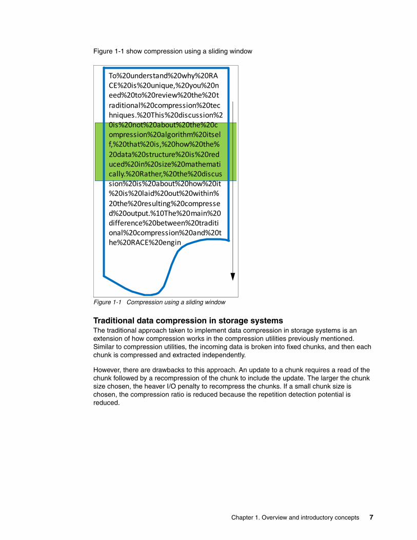
Figure 1-1 show compression using a sliding window
Figure 1-1 Compression using a sliding window
Traditional data compression in storage systemsThe traditional approach taken to implement data compression in storage systems is an extension of how compression works in the compression utilities previously mentioned. Similar to compression utilities, the incoming data is broken into fixed chunks, and then each chunk is compressed and extracted independently.
However, there are drawbacks to this approach. An update to a chunk requires a read of the chunk followed by a recompression of the chunk to include the update. The larger the chunk size chosen, the heaver I/O penalty to recompress the chunks. If a small chunk size is chosen, the compression ratio is reduced because the repetition detection potential is reduced.
To%20understand%20why%20RACE%20is%20unique,%20you%20need%20to%20review%20the%20traditional%20compression%20techniques.%20This%20discussion%20is%20not%20about%20the%20compression%20algorithm%20itself,%20that%20is,%20how%20the%20data%20structure%20is%20reduced%20in%20size%20mathematically.%20Rather,%20the%20discussion%20is%20about%20how%20it%20is%20laid%20out%20within%20the%20resulting%20compressed%20output.%10The%20main%20difference%20between%20traditional%20compression%20and%20the%20RACE%20engin
Chapter 1. Overview and introductory concepts 7

Figure 1-2 shows an example of how the data is broken into fixed size chunks (in the upper-left side of the figure). It also shows how each chunk gets compressed independently into chunks (in the upper-right side of the figure). The resulting compressed chunks are stored sequentially in the compressed output. Although this approach is an evolution from compression utilities, it is limited to low performance use cases. This limitation is mainly because it does not provide real random access to the data.
Figure 1-2 Traditional data compression
Random Access Compression EngineThe IBM patented Random Access Compression Engine alters the traditional approach to compression. It uses variable-size chunks for the input, and fixed-size chunks for the output.
This method enables an efficient and consistent method to index the compressed data because it is stored in fixed-size containers.
1
2
3
4
5
1 2
3 4
5
Compressed Data
1
2
3
4
5
8 Accelerate with IBM FlashSystem V840 Compression

Figure 1-3 show Random Access Compression with fixed output chunks.
Figure 1-3 Random Access Compression Engine (RACE)
1.2.3 Temporal locality
Both compression utilities and traditional storage systems compression compress data by finding repetitions of bytes within the chunk that is being compressed. The compression ratio of this chunk depends on how many repetitions can be detected within the chunk. The number of repetitions is affected by how much the bytes stored in the chunk are related to each other. The relation between bytes is driven by the format of the object. For example, an office document might contain textual information, and an embedded drawing (like Figure 1-3). Because the chunking of the file is arbitrary, it has no notion of how the data is laid out within the document. Therefore, a compressed chunk can be a mixture of the textual information and part of the drawing. This process yields a lower compression ratio because mixing the different data types together cause a suboptimal dictionary of repetitions. That is, fewer repetitions can be detected because a repetition of bytes in a text object is unlikely to be found in a drawing.
This traditional approach to data compression is also called location-based compression. The data repetition detection is based on the location of data within the same chunk.
Temporal compressionRACE offers a technology leap beyond location-based compression, which is temporal compression. When host writes arrive to RACE, they are compressed and fill up fixed size chunks also called compressed blocks. Multiple compressed writes can be aggregated into a single compressed block. A dictionary of the detected repetitions is stored within the compressed block. When applications write new data or update existing data, it is typically sent from the host to the storage system as a series of writes. Because these writes are likely to originate from the same application and be of the same data type, more repetitions are usually detected by the compression algorithm.
This type of data compression is called temporal compression because the data repetition detection is based on the time the data was written into the same compressed block. Temporal compression adds the time dimension that is not available to other compression
1
2
3
4
5
Compressed Data (RACE)
1
2
3
4
5
12
3
45
Chapter 1. Overview and introductory concepts 9

algorithms. It offers a higher compression ratio because the compressed data in a block represents a more homogeneous input data.
Figure 1-4 shows (in the left part of the figure) how three writes sent one after the other by a host end up in different chunks. They get compressed in different chunks because their location in the volume is not adjacent. This yields a lower compression ratio because the same data must be compressed non-natively by using three separate dictionaries. When the same three writes are sent through RACE (in the right part of the figure), the writes are compressed together by using a single dictionary. This yields a higher compression ratio than location-based compression. Applications often read those three writes back also with temporal correlation, in which case the read benefits from being written together.
Figure 1-4 Location-based versus temporal compression
1.3 IBM FlashSystem V840 components
IBM FlashSystem V840 flash technology with Real-time Compression is available as a solution in a compact 6U form factor. FlashSystem V840 improves business application availability and delivers greater resource utilization so you can get the most from your storage resources, and achieve a simpler, more scalable, and cost efficient IT Infrastructure. It uses IBM Storwize family functions, management tools, and interoperability. This product combines the performance of FlashSystem architecture with the advanced functions of software-defined storage to deliver performance, efficiency, and functions that meets the needs of enterprise workloads that demand IBM MicroLatency™ response times.
1.3.1 FlashSystem V840
FlashSystem V840 is a rack-mount shared flash memory device that is based on enterprise multi-level cell (eMLC) flash technology. It provides macro efficiency with up to 40 TB of protected capacity in a 6U form factor, enterprise reliability through IBM Variable Stripe RAID™ and two-dimensional flash RAID, and extreme performance with MicroLatency. FlashSystem V840 provides advanced data services, including business continuity with replication services, data protection with IBM FlashCopy® services, and higher storage efficiency with thin provisioning, Real-time Compression, IBM Easy Tier®, external virtualization, and space-efficient copies.
To%20understand%20why%20RACE%20is%20unique,%20you%20need%20to%20review%20the%20traditional%20compression%20techniques.%20This%20discussion%20is%20not%20about%20the%20compression%20algorithm%20itself,%20that%20is,%20how%20the%20data%20structure%20is%20reduced%20in%20size%20mathematically.%20Rather,%20the%20discussion%20is%20about%20how%20it%20is%20laid%20out%20within%20the%20resulting%20compressed%20output.%10The%20main%20difference%20between%20traditional%20compression%20and%20the%20RACE%20engin
1
2
3
Location Compression
Window#
1 2 3
Temporal Compression
Window
= Host Write
10 Accelerate with IBM FlashSystem V840 Compression

The FlashSystem V840 baseline configuration (Figure 1-5) is composed of the following components:
� Two FlashSystem V840 Control Enclosures, with two optional compression accelerator cards per control enclosure
� One FlashSystem V840 Storage Enclosure
This FlashSystem V840 configuration is called a building block. You can scale to higher performance and load using up to four building blocks and adding up to four extra FlashSystem V840 storage enclosures. “FlashSystem V840 scaling” on page 12 describes scaling of FlashSystem V840.
FlashSystem V840 uses two different fabrics. One fabric, the internal interconnect, connects the control enclosures and the storage enclosure, and the external fabric connects hosts and other storage.
Figure 1-5 FlashSystem V840 components
Figure 1-5 shows the FlashSystem V840 components:
1. First FlashSystem V840 controller node1 (AC1)2. Second FlashSystem V840 controller node1 (AC1)3. FlashSystem V840 flash memory enclosure (AE1)
Real-time Compression running on two cores (dual instance)FlashSystem V840 Software V7.4 includes the potential for improvements to Real-time Compression performance by taking better advantage of the processor cores available to it, and by running a second instance of Real-time Compression. See the product documentation for the prerequisites for taking full advantage of this capability. At the time of this release, FlashSystem V840 can take advantage of this capability when using the control enclosures and the compression acceleration cards. Each of the two controller nodes has six slots for PCI Cards. Slot 4 and slot 6 are reserved for the Real-time Compression accelerator cards.
Chapter 1. Overview and introductory concepts 11

You can configure FlashSystem V840 either without compression acceleration cards or with two compression acceleration cards per controller node (Figure 1-6).
Figure 1-6 FlashSystem V840 rear view
Figure 1-7 shows the FlashSystem V840 Real-time accelerator card.
Figure 1-7 FlashSystem V840 Real-time accelerator card
FlashSystem V840 scalingFlashSystem V840 has a scalable architecture that allows flash capacity to be added (scaled up) to support high capacity needs. The virtualized system can also be expanded (scaled out) to support higher IOPS and bandwidth, or the solution can be simultaneously scaled up and out to improve capacity, IOPS, and bandwidth while maintaining MicroLatency. FlashSystem V840 has the following scalability features per building block:
� Slots for up to 12 hot-swappable flash memory modules (1 TB, 2 TB, or 4 TB modules)
– Configurable 2 - 40 TB of capacity for increased flexibility per storage enclosure
� FlashSystem V840 has the following flexible scalability configuration options:
– Base configuration, the building block– Add more flash capacity– Scale out: Expand virtualized system– Scale up and out: Add more flash capacity and expand virtualized system
IMM Port
PCIe expansion slots
Technician Port
1 Gb iSCSI ports
750W PSUs
4 USB ports
Mgmt ports
Slot 1Slot 2Slot 3
Slot 4Slot 5Slot 6
12 Accelerate with IBM FlashSystem V840 Compression

The FlashSystem V840 building block is available with different IO interfaces:
� Three 8 Gb FC IO cards
The internal interconnect does not use a switch, The control enclosures and the storage enclosure are directly connected. You must add four FC switches for scaling.
� Four IO cards, two 16 Gb FC cards for the internal interconnect
The internal interconnect always uses switches when 16 Gb FC cards are used for the internal interconnect. You need two 16 Gb FC switches for scaling. The connection to the host and to other storage can be one of the following combinations:
– Two 8 Gb FC cards– Two 16 Gb FC cards– Two 10 Gb FCoE/ iSCSI cards
The 16 Gb FC cards are equipped with two ports each. All other cards are equipped with four ports each.
FlashSystem V840 scale outYou start with one building block and add up to three more building blocks to get at most four building blocks.
FlashSystem V840 scale upYou start with one, two, three, or for building blocks and add up to four more FlashSystem V840 storage enclosures.
In a maximal configuration, you can have eight controller nodes from four building blocks and eight storage enclosures.
Figure 1-8 shows different scaling options for FlashSystem V840. The FC switches in this figure are only used for the internal 16 Gb FC connections. For 8 Gb FC connections, four switches are needed.
Figure 1-8 Possible FlashSystem V840 scaling options
Storage enclosures (0-4)
FC Switches
Building Blocks (1-4)
Scale Out (performance & capacity)
1 BB 2 BB 3 BB 4 BB
Scale UP Capacity
1 F
Legend:1F: Fixed – directly cabled
BB: Building Block – need switches
Chapter 1. Overview and introductory concepts 13

Table 1-1 shows the host port count per building block configuration (one, two, three, or up to four building blocks).
Table 1-1 Host port count per building blocks
1.3.2 Software stack code level 7.4
It is important to understand where the RACE technology is implemented in the FlashSystem V840 controller enclosure (AC1) software stack. This location determines how it applies to the data path inside the controller nodes and also to the storage area network (SAN). RACE technology is implemented into the FlashSystem V840 thin provisioning layer, and is an organic part of the stack. The FlashSystem V840 software stack is shown in Figure 1-9. Compression is transparently integrated with existing system management design. All of the FlashSystem V840 advanced features are supported on compressed volumes. You can create, delete, migrate, map (assign), and unmap (unassign) a compressed volume as though it were a fully allocated volume. This compression method provides nondisruptive conversion between compressed and uncompressed volumes. This conversion provides a uniform user-experience and eliminates the need for special procedures when dealing with compressed volumes.
Figure 1-9 FlashSystem V840 software stack
8 Gb FC 16 Gb FC 10 Gb FCoE 8 Gb & 10 GB IP Mirror
16 Gb FC & 10 Gb Mirror
10 Fixed 8 N/A N/A
1 BB 16 8 8 8,8 4,8
2 BB 32 16 16 16,16 8,16
3 BB 48 24 24 24,24 12,24
4 BB 64 32 32 32,32 16,32
Front End
Remote Copy
Upper Cache
Flash Copy
Volume Mirror
Thin ProvisioningRtC
Host I/O
Thin ProvisioningRtC
Lower Cache Lower Cache
Virtualization Virtualization
BackendBackend
Random Access Compression
Engine
RtC RtC
= RACEHW & SW Components
14 Accelerate with IBM FlashSystem V840 Compression
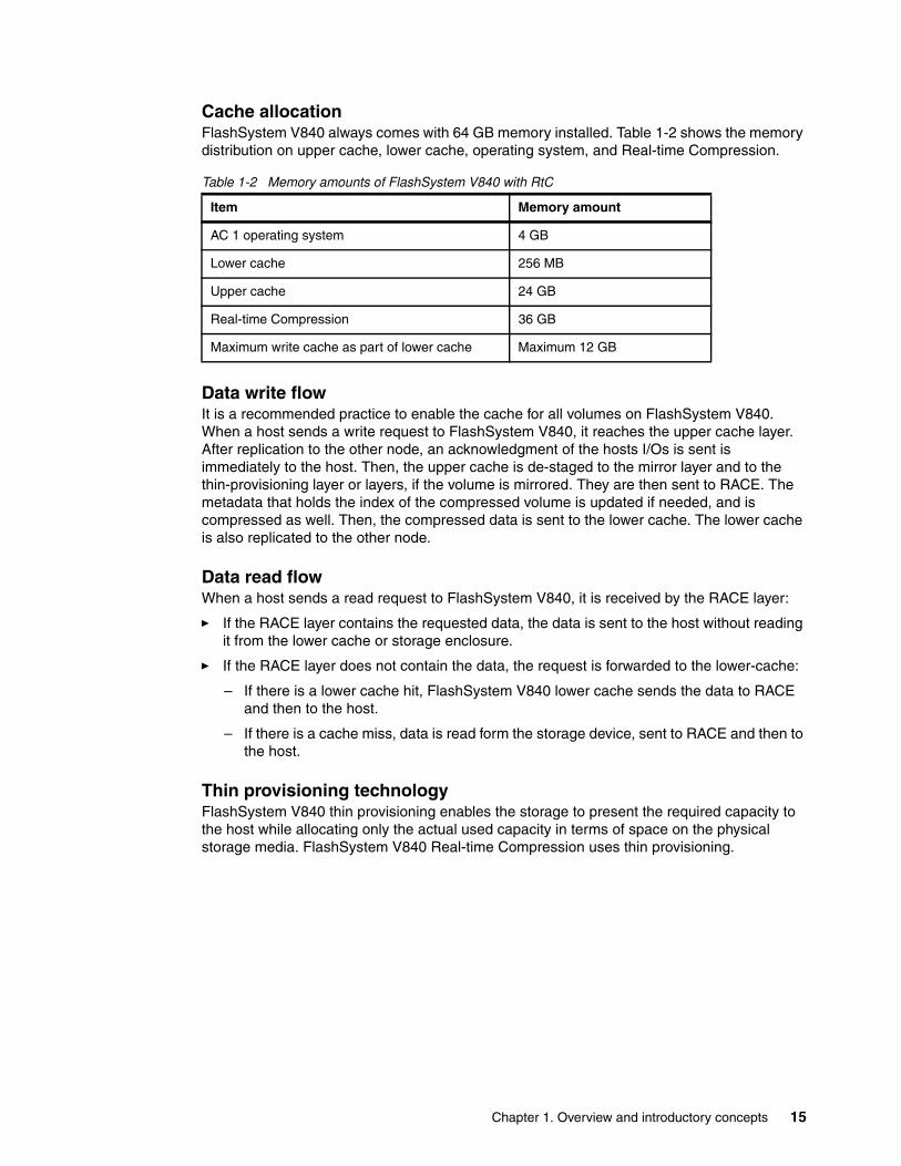
Cache allocationFlashSystem V840 always comes with 64 GB memory installed. Table 1-2 shows the memory distribution on upper cache, lower cache, operating system, and Real-time Compression.
Table 1-2 Memory amounts of FlashSystem V840 with RtC
Data write flowIt is a recommended practice to enable the cache for all volumes on FlashSystem V840. When a host sends a write request to FlashSystem V840, it reaches the upper cache layer. After replication to the other node, an acknowledgment of the hosts I/Os is sent is immediately to the host. Then, the upper cache is de-staged to the mirror layer and to the thin-provisioning layer or layers, if the volume is mirrored. They are then sent to RACE. The metadata that holds the index of the compressed volume is updated if needed, and is compressed as well. Then, the compressed data is sent to the lower cache. The lower cache is also replicated to the other node.
Data read flowWhen a host sends a read request to FlashSystem V840, it is received by the RACE layer:
� If the RACE layer contains the requested data, the data is sent to the host without reading it from the lower cache or storage enclosure.
� If the RACE layer does not contain the data, the request is forwarded to the lower-cache:
– If there is a lower cache hit, FlashSystem V840 lower cache sends the data to RACE and then to the host.
– If there is a cache miss, data is read form the storage device, sent to RACE and then to the host.
Thin provisioning technologyFlashSystem V840 thin provisioning enables the storage to present the required capacity to the host while allocating only the actual used capacity in terms of space on the physical storage media. FlashSystem V840 Real-time Compression uses thin provisioning.
Item Memory amount
AC 1 operating system 4 GB
Lower cache 256 MB
Upper cache 24 GB
Real-time Compression 36 GB
Maximum write cache as part of lower cache Maximum 12 GB
Chapter 1. Overview and introductory concepts 15

Figure 1-10 shows potential savings due to thin provisioning and Real-time Compression.
Figure 1-10 Traditional volume compared to thin provisioned volume and to compressed volume
IBM Easy TierIBM Easy Tier is a performance function that automatically and non-disruptively migrates date to adequate performance tiers. There are three tier levels:
� Flash: Used for frequently accessed data. This is called Tier-0.� Enterprise: Used for normal accessed data. This is called Tier-1.� Near line: Used for least accessed data. This is called Tier-2.
The Easy Tier algorithm moves data according to different parameters, such as data usage, cost of migration, usage of the tiers, performance characteristics of the tiers, and other parameters of higher or lower tiers. When using Real-time Compression, data from different source blocks can be compressed together and be written in only one block to a new location on the storage enclosure. With Real-time compression, the writes are always new blocks for the Easy Tier layer. Therefore, Easy Tier will only consider block reads when used in combination with Real-time compression.
TraditionalVolume
Thin Provisioned Volume
Real-time Compressed Volume
Detected Space by the Host
Free Space (allocated)
Free Space (not allocated)
Used Space (allocated)
Used Space(compressed)
16 Accelerate with IBM FlashSystem V840 Compression

Figure 1-11 shows the Easy Tier feature of moving data to its adequate performance tier.
Figure 1-11 Easy Tier data movement
1.4 Licensing
For any FlashSystem V840 storage enclosure, Real-time Compression is included in the base software. If Real-time Compression is needed on externally virtualized storage, a separate license is required per enclosure.
When ordering the FlashSystem V840, generally order the solution with the compression accelerator cards.
The following steps show how to apply a Real-time Compression license for two flash enclosures attached to FlashSystem V840.
Note: Easy Tier will only consider block reads when used in combination with Real-time Compression.
Less Active DataMigrates Down
Flash Arrays Tier 0
Active DataMigrates Up
Enterprise HDD Tier 1
Neraline HDDTier 2
Chapter 1. Overview and introductory concepts 17

To apply the FlashSystem V840 compression license, complete these steps:
1. Click the Settings icon and select System → Licensing as shown in Figure 1-12.
Figure 1-12 Applying FlashSystem V840 Real-time Compression license
2. Enter the total number of licensed enclosures that are licensed for compression.
3. Click Apply Changes as shown in Figure 1-12 to complete the progress as shown in Figure 1-13.
Figure 1-13 FlashSystem V840 update license task completed
18 Accelerate with IBM FlashSystem V840 Compression

Using the CLI you can use the command shown in Figure 1-13.
Example 1-1 CLI command to enter RtC licenses and to list licenses
>svctask chlicense -compression 2
>svcinfo lslicenseused_flash 0.00used_remote 0.00used_virtualization 23.02license_flash 0license_remote 0license_virtualization 3license_physical_disks 0license_physical_flash offlicense_physical_remote offused_compression_capacity 9.47license_compression_capacity 0license_compression_enclosures 2license_easy_tier 0
Chapter 1. Overview and introductory concepts 19

20 Accelerate with IBM FlashSystem V840 Compression

Chapter 2. Planning your environment
This chapter describes planning guidelines that contribute to successful solution design. It addresses the requirements for configuring Real-time Compression (RtC) and the best candidate data sets for using compression in IBM FlashSystem V840.
This chapter includes the following sections:
� Candidate data sets for compression� Candidate workloads for compression� Requirements� Comprestimator� General guidelines
2
© Copyright IBM Corp. 2015. All rights reserved. 21

2.1 Candidate data sets for compression
Some common data types are good candidates for compression, and others are not. Distinguishing between them requires you to understand the compressibility of your data.
2.1.1 Data types
The best candidates for data compression are data types that are not compressed by nature. Viable candidates include data types that are involved in many workloads and applications, such as databases, character/ASCII based data, email systems, server virtualization, CAD/CAM, software development systems, and vector data.
The following examples represent workloads and data that are already compressed.
� Compressed audio, video, and image file formats: File types such as jpeg, png, mp3, medical imaging (DICOM), and mpeg2
� Compressed user productivity file formats: Microsoft Office 2007 and newer formats (pptx, docx, xlsx, and so on), pdf files, Microsoft Windows executable files (exe), and so on
� Compressed file formats: File types such as zip, gzip, rar, cab, and tgz
In cases where data is encrypted by the client or the application used, no savings can be achieved by using any compression method. Because of the high entropy found in encrypted data, compression algorithms cannot find similarities or repetitions within them, and are ineffective. Do not spend system resources on compressing encrypted data or storing that data on compressed volumes.
2.1.2 Volume types
When planning for compression, you need to understand the nature of the data that is contained within a volume. There are two basic types of volumes to consider: Homogeneous and heterogeneous volumes. As a rule, homogeneous volumes are better candidates for compression. The following sections explain the types of volumes and how to decide whether a volume should be compressed.
Note: Use compression for data with a compression ratio of 40% and higher. Do not attempt to compress data that is already compressed by nature or data that has a low compression ratio (below 25% savings). Selecting such data to be compressed provides little or no savings while consuming processor resources by generating additional I/Os. Compression relies on reduced I/Os to achieve the same or better performance than an uncompressed volume. In addition, if data is already compressed through another application or process, that data should not be stored in a compressed volume on FlashSystem V840. Use the Comprestimator tool or have a full understanding of the data types before attempting compression.
22 Accelerate with IBM FlashSystem V840 Compression
Homogeneous volumesHomogeneous volumes are volumes that contain data that was created by a single application, and store data of the same kind. The following examples are application workloads that typically store their data on homogeneous volumes:
� Databases such as IBM DB2®, Oracle, and MS-SQL� Email such as IBM Lotus® Notes®� Server virtualization such as VMware, Hyper-V, and KVM
Homogeneous volumes are good candidates for compression because most of the data stored in such volumes achieves similar compression across the volume. They are good candidates if the homogeneous volume contains compressible data.
Heterogeneous volumesHeterogeneous volumes are volumes that contain diverse content (different data types). If the volume contains a mix of compressible and uncompressible data, system resources are spent on data that has a low compression ratio. Because system resources are used without many gains, avoid compressing such volumes, and compress only volumes that contain compressible, unencrypted data.
2.2 Candidate workloads for compression
When FlashSystem V840 Real-time Compression is used on a compressible workload, the resulting solution has up to a 5:1 reduction in cost and capacity while maintaining up to a 5x reduction in latency compared to disk drive based systems.
Even in a worst case workload scenario for the Real-time Compression (RtC) component, FlashSystem V840 performance typically is better than what you achieve with equivalent capacity of spinning disk storage.
Temporal locality / Random prefetchTemporal locality is a term that describes the relationship data has with data that was written during the same time period. With Real-time Compression, write requests are grouped and written into 32 KB compressed blocks. These write requests can be consecutive logical addresses for sequential write workloads, or the addresses can be spread across the entire volume in the case of random write workloads. In either case, the write requests that were received at the same time have temporal locality. Depending on the compressibility of the data and the size of the write request, the 32 KB compressed block can contain one to hundreds of the requested write blocksize. When data from a compressed block is then read, the entire contents of the block are decompressed and available. The number of read requests satisfied from the data in the compressed block affects the efficiency and performance of the system. You can think of this as a type of random prefetch or compression cache hit.
Application typesThe following common workloads are typically suitable for use with compression:
� Database applications: Oracle, IBM DB2, Microsoft SQL, SAP
� Server/Desktop virtualization: VMWare, KVM, Hyper-V
� Messaging: IBM Notes, Microsoft Exchange (if attachments are not compressed file types)
� Others: Engineering, collaboration, scientific
Chapter 2. Planning your environment 23

Workload guidelinesReal-time Compression excels in most production I/O workloads while being efficient on system resources. Most sequential workloads are good candidates for Real-time Compression. Use the following general guidelines to decide whether a specific volume’s workload is optimal for compression based on application I/O patterns:
� Small block, random access, poor cache hit: Non-optimal workload for RtC. Evaluate production workload with compression to determine whether performance is sufficient.
� Medium/Large block, random access, poor cache hit: Evaluate workload with compression.
� Pseudo Random access, expect compression cache hits / random prefetch hits: Optimal workload for RtC.
� Sequential Workloads: Evaluate workload with compression. Typically good candidates for Real-time Compression.
� Sequential Read preceded by random writes: Evaluate workload with compression. Likely have extra read activity due to compression cache misses.
2.3 Requirements
The FlashSystem V840 model AC1 Control Enclosure offers several features that are required for Real-time Compression.
2.3.1 Software requirements
IBM FlashSystem V840 Software V7.4 (5639-FS7) requires an IBM FlashSystem V840 Storage System (9846-AC1 and 9846-AE1, or 9848-AC1 and 9848-AE1). It is preinstalled on, and included with, these systems.
Real-time compression running on two cores (dual instance)FlashSystem V840 Software V7.4 includes the potential for improvements to Real-time Compression performance by taking better advantage of the processor cores available to it and running a second instance of Real-time Compression on the second core. See the product documentation for the prerequisites for taking full advantage of this capability.
At the time of writing, FlashSystem V840 can take advantage of this capability when using the control enclosures (9846-AC1 and 9848-AC1) and at least one compression acceleration card (with the selection of hardware feature #AH1A).
The base license for FlashSystem V840, 5639-FS7, when used for the FlashSystem V840 Storage Enclosure can now be used to satisfy the license condition for that V840 Storage Enclosure's use of Real-time Compression (5639-FC7) and Remote Mirror (5639-FR7). In this condition, it is still recommended to order the compression accelerator adapters (Feature #AH1A) for the FlashSystem V840 Control Enclosures in the system configuration.
For details of how IBM FlashSystem V840 Software V7.4 improves performance of Real-time Compression and includes license compatibility with SmartCloud Virtual Storage Center, see Software Announcement 214-429 at:
http://www-01.ibm.com/common/ssi/ShowDoc.wss?docURL=/common/ssi/rep_ca/9/897/ENUS214-429/index.html&lang=en&request_locale=en
24 Accelerate with IBM FlashSystem V840 Compression
2.3.2 Hardware requirements
Each IBM FlashSystem V840 Control Enclosure (9846-AC1 or 9848-AC1) supports two hardware compression accelerator cards (Feature Code AH1A) to increase the Real-time Compression performance.
Additionally each V840 Control Enclosure comes configured with 64 GB of memory and two 8-core processors.
2.3.3 Compressible data
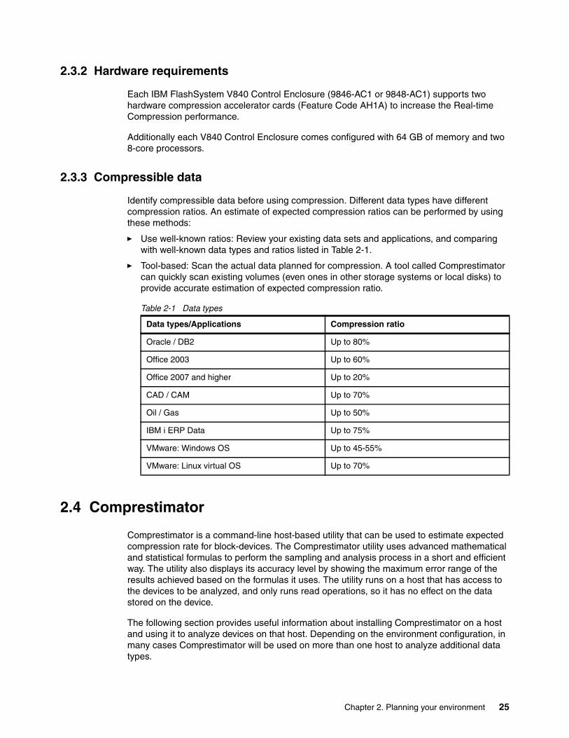
Identify compressible data before using compression. Different data types have different compression ratios. An estimate of expected compression ratios can be performed by using these methods:
� Use well-known ratios: Review your existing data sets and applications, and comparing with well-known data types and ratios listed in Table 2-1.
� Tool-based: Scan the actual data planned for compression. A tool called Comprestimator can quickly scan existing volumes (even ones in other storage systems or local disks) to provide accurate estimation of expected compression ratio.
Table 2-1 Data types
2.4 Comprestimator
Comprestimator is a command-line host-based utility that can be used to estimate expected compression rate for block-devices. The Comprestimator utility uses advanced mathematical and statistical formulas to perform the sampling and analysis process in a short and efficient way. The utility also displays its accuracy level by showing the maximum error range of the results achieved based on the formulas it uses. The utility runs on a host that has access to the devices to be analyzed, and only runs read operations, so it has no effect on the data stored on the device.
The following section provides useful information about installing Comprestimator on a host and using it to analyze devices on that host. Depending on the environment configuration, in many cases Comprestimator will be used on more than one host to analyze additional data types.
Data types/Applications Compression ratio
Oracle / DB2 Up to 80%
Office 2003 Up to 60%
Office 2007 and higher Up to 20%
CAD / CAM Up to 70%
Oil / Gas Up to 50%
IBM i ERP Data Up to 75%
VMware: Windows OS Up to 45-55%
VMware: Linux virtual OS Up to 70%
Chapter 2. Planning your environment 25

Comprestimator is supported and as of the time this paper was written, can be used on the following client operating system versions:
� Windows 2003 Server, Windows 7, Windows 2008 Server, Windows 8, Windows 2012� ESXi 4, 5� IBM AIX® 6.1, 7� Red Hat Enterprise Linux Version 5.x, 6� HP-UX 11.31� Sun Solaris 10,11� SUSE SLES 11� Ubuntu 12� CentOS 5.x
Comprestimator is available from IBM at:
http://www14.software.ibm.com/webapp/set2/sas/f/comprestimator/home.html
This link includes the installation instructions for the Comprestimator tool.
2.4.1 Installing Comprestimator
Comprestimator must initially be installed on a supported Windows operating system (see list above). After installation completes, the binary files for other supported operating systems are available in the Windows installation folder.
By default, the files are copied to:
In Windows 64-bit: C:\Program Files (x86)\IBM\Comprestimator
In Windows 32-bit: C:\Program Files\IBM\Comprestimator
After transferring the operating system-dependent Comprestimator tools to your system, follow the installation instructions that are provided on the Comprestimator download page.
The program invocation is different on different operating systems, but the output is the same.
2.4.2 Using Comprestimator
The following topic discusses how to use the Comprestimator utility.
Comprestimator syntaxExample 2-1 shows Comprestimator syntax for IBM AIX.
Example 2-1 comprestimator syntax for AIX
./comprestimator_aix
Comprestimator version: 1.5.1.1 (Build w0087)
Usage:
comprestimator [ -h | -d device [-c filename] [-v] [-p number_of_threads] [-P] [-I] [--storageVer=version] [--config=task_file]
-d device name Path of device to analyze (e.g.: /dev/hdisk0)
-p number Number of threads (default 10)
-c Export the results to a CSV file
26 Accelerate with IBM FlashSystem V840 Compression

-v Verbose output
-h Print this help message
-P Display results using a paragraph format
-I Allow larger scale of storage io-error threshold rate (up to 5%)
--config=file Configuration file that contains list of devices to analyze
--storageVer=version Target Storwize/SVC/FlashSystem storage system version. Options include 6.4, 7.1, 7.2, 7.3, 7.4; default is 7.4
Comprestimator outputAn example of Comprestimator output is shown in Figure 2-1.
Figure 2-1 Example of Comprestimator output
The output categories are explained in Table 2-2.
Table 2-2 Comprestimator output explanations
Header Explanation
Sample# The number of the current sample reported
Device The device name used in the scan
Size (GB) The total size of the device as reported by the operating system, in gigabytes
Compressed Size (GB) The estimated size of the device if it is compressed using FlashSystem V840 Real-time Compression, in gigabytes
Total Savings (GB) The total estimated savings from thin-provisioning and compression, in gigabytes
Total Savings (%) The estimated savings from thin-provisioning and compression, in percentage of the size of the device.This value is calculated in the following method:Total Savings (%) = 1-( Compressed Size (GB) / Size (GB) )
Thin Provision Savings (%) The estimated savings from thin provisioning (areas with zeros are stored using minimal capacity).
Compression Savings (%) The estimated savings from compression
Compression Accuracy Range (%)
The accuracy of the estimate provided by Comprestimator. The results provided are estimated based on samples from the device, and therefore might be lower or higher than the actual compression that would be achieved. The approximate accuracy of the results is represented as a percentage of the total size of the device.For example, if the estimated Compression Savings (%) is 67%, and the Compression Accuracy Range is 5%, the actual compression savings (in percentage) if this device is compressed on FlashSystem V840 is between 62% and 72%.
Chapter 2. Planning your environment 27

FlashSystem V840 GUI results from adding a compressed mirrored copyIn this example, a generic (fully allocated) FlashSystem V840 volume has been used. After adding a compressed mirrored copy to the volume, you can see the results using the FlashSystem V840 GUI or by using the command-line tool. Figure 2-2 depicts the volume list in the GUI.
Figure 2-2 FlashSystem V840 GUI: Volume list
To see all of the capacity information, you must extend the normal view, as shown in Figure 2-3.
Figure 2-3 Properties view of volume Database_RTC
28 Accelerate with IBM FlashSystem V840 Compression

The fully allocated volume Database_RTC has a capacity of 200 GiB. Table 2-3 shows the size of the uncompressed fully allocated volume (Copy 0), the RtC mirror (Copy 1), and the estimated size given by Comprestimator. The compression savings seen by the controller nodes are in the result range provided by Comprestimator.
Table 2-3 Comprestimator estimated and RtC achieved savings
It is important to understand block-device behavior when analyzing traditional (fully allocated) volumes. Traditional volumes that were created without initially zeroing the device might contain traces of old data in the block-device level. Such data will not be accessible or viewable at the file system level. When files are deleted from a file system, the space they occupied before being deleted is freed and available to the file system. This is the case, even though the data on disk was not actually deleted but rather the file system index and pointers were updated to reflect this change. Therefore, there is inactive data at the block-device level that is not shown at the file system level.
When using Comprestimator to analyze such volumes, the expected compression results reflect the compression rate that will be achieved for all the data in the block-device level, including the traces of inactive data. This simulates the volume mirroring process of the analyzed device into a compressed volume. Later, when volume mirroring is used to compress the data on the storage system, it processes all data on the device (including both active data and inactive data) and compresses it. After that, when you store more active data on the compressed volume, traces of inactive data will start getting deleted by new data that is written into the volume. As more active data accumulates in the device, the compression rate achieved is adjusted to reflect the accurate savings achieved for the active data. This block-device behavior is limited to traditional volumes and will not occur when analyzing thinly provisioned volumes.
To reduce the impact of block-device and file system behavior mentioned above, use Comprestimator to analyze volumes that contain as much active data as possible rather than volumes that are mostly empty. This increases the accuracy level and reduces the risk of analyzing old data that is already deleted, but might still have traces on the device
2.5 General guidelines
The following are general guidelines to get the best compression results on FlashSystem V840 workloads:
� Use compression for workloads that tend to have good temporal locality, which are workloads where data is read in a similar order to how the data was written.
� Use compression for sequential workloads.
� Use compression on homogeneous volumes. These are volumes containing data from one application or data with the same expected compression factor.
Copy Host capacity(GiB)
Used (BeforeCompression)
Real capacity(GiB)
Used capacity(GiB)
Compressionsavings (%)
0:Generic
200 200 200
1:RtC
200 189.31 59.48 55.48 70.69
Comprestimatorresults
200 55.5 67.3 - 77.3
Chapter 2. Planning your environment 29

� Avoid using any client, file system, or application compression when using FlashSystem V840 compressed volumes
� Avoid using any client, file system, or application encryption when using FlashSystem V840 compressed volume. Encrypted data is not compressible.
� Avoid compression on FlashSystem V840 volumes that are used to store homogeneous or heterogeneous data types that contain compressed data or compressed file types.
� To get the best information about the savings, you can start by using the Comprestimator utility to see whether your data is a good candidate for compression. This host-based utility offers fast and accurate estimates of an expected compression rate for block devices. Use Comprestimator to estimate the compression ratio, and implement compression on volumes that have a compression ratio above 40%, and evaluate workload on volumes with low compression ratio (<40%).
Figure 2-4 shows different types of application-dependent volumes and their compression savings. You must add the real capacity and used capacity columns to get the information about the compressed capacity in the GUI.
Figure 2-4 FlashSystem V840 GUI information about compression savings
The first four volumes should have great savings when used with Real-time Compression
30 Accelerate with IBM FlashSystem V840 Compression

Chapter 3. Setup and configuration
This chapter describes how to create a compressed volume on IBM FlashSystem V840. The volume is mapped to a host. FlashSystem V840 supports different operating systems from different vendors. How to get the latest attachment requirements and drivers for all supported operating systems is also described.
This chapter includes the following sections:
� Configuring compressed volumes using FlashSystem V840� Host configuration best practices
3
© Copyright IBM Corp. 2015. All rights reserved. 31

3.1 Configuring compressed volumes using FlashSystem V840
This section describes how to create compressed volume. FlashSystem V840 uses five different presets for volumes:
� Generic: Fully allocated volumes using the volume size from the selected storage pool.
� Thin Provision: Volumes that show to the hosts the volume size, but use only the capacity that is written from the host of the selected storage pool.
� Mirror: A volume with two fully allocated mirrors. The two mirrors can be in different storage pools, and therefore protect the host from failures of a storage pool-
� Thin Mirror: A mirrored volume but it uses only the capacity that is written from the host for the two copies.
� Compressed: A volume where the date will be compressed using RACE. This volume is thin provisioned as well.
3.1.1 Creating a compressed volume
To create a volume using the GUI, complete these steps:
1. Go to the Volume window and click Volumes → Volumes as shown in Figure 3-1.
Figure 3-1 Selecting the Volume window
32 Accelerate with IBM FlashSystem V840 Compression

2. From the volume list, click Create Volume as shown in Figure 3-2.
Figure 3-2 Create volume
3. Select the Compressed preset and select the storage pool. In this example, the FlashSystem V840 storage enclosure pool named V840_AE1_LAB_1 is used, as shown in Figure 3-3. The small icon next to the free capacity shows that there is already at least one compressed volume using this pool.
Figure 3-3 Select compression preset and FlashSystem V840 flash memory pool
Chapter 3. Setup and configuration 33

4. Select the pool and provide number of volumes, size (or capacity), and name for the volumes as shown in Figure 3-4.
Figure 3-4 Providing volume information.
5. Select Advanced to open the Advanced Settings. This window contains three tabs:
– Characteristics
You can set these characteristics as shown in Figure 3-5 on page 35:
Format before Use: Formatting writes zeros to the volume. This is not required for compressed volumes.
Locality: Each volume has a preferred node. This property can be used to balance the IO load between nodes.
UDID (OpenVMS): The unit device identifier (UDID) used by Open VMS hosts to identify this volume. This property should only be used for OPEN VMS hosts.
34 Accelerate with IBM FlashSystem V840 Compression
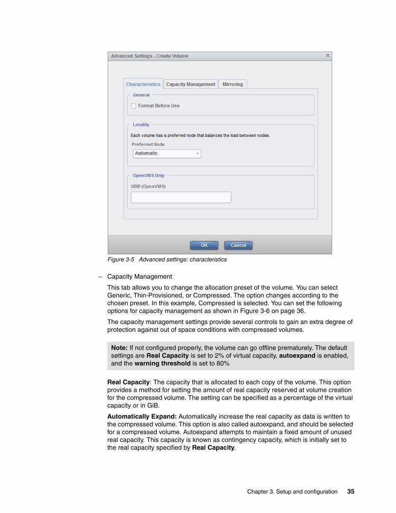
Figure 3-5 Advanced settings: characteristics
– Capacity Management
This tab allows you to change the allocation preset of the volume. You can select Generic, Thin-Provisioned, or Compressed. The option changes according to the chosen preset. In this example, Compressed is selected. You can set the following options for capacity management as shown in Figure 3-6 on page 36.
The capacity management settings provide several controls to gain an extra degree of protection against out of space conditions with compressed volumes.
Real Capacity: The capacity that is allocated to each copy of the volume. This option provides a method for setting the amount of real capacity reserved at volume creation for the compressed volume. The setting can be specified as a percentage of the virtual capacity or in GiB.
Automatically Expand: Automatically increase the real capacity as data is written to the compressed volume. This option is also called autoexpand, and should be selected for a compressed volume. Autoexpand attempts to maintain a fixed amount of unused real capacity. This capacity is known as contingency capacity, which is initially set to the real capacity specified by Real Capacity.
Note: If not configured properly, the volume can go offline prematurely. The default settings are Real Capacity is set to 2% of virtual capacity, autoexpand is enabled, and the warning threshold is set to 80%
Chapter 3. Setup and configuration 35

Warning Threshold: When the used capacity first exceeds the warning threshold, an event is raised indicating that more real capacity is needed. You can manually expand the real capacity that is allocated to the volume. If autoexpand is enabled, you will receive this event notification but do not need to adjust the real capacity manually.
Figure 3-6 Advanced settings: capacity management
– Mirroring
If you want to create a mirrored compressed volume, you can check Create Mirrored Copy in Mirroring tab as shown in Figure 3-7. If you choose to create a mirrored copy, you must select a secondary pool for the mirror after closing the Advanced Settings.
Figure 3-7 Creating a mirrored compressed volumes using Advanced Settings
6. The next step creates the volume. Select Create and the values from Figure 3-4 on page 34 with optional changes from the advanced settings are used to create the volume. Mapping the volumes to a host is covered in “Creating a compressed volume using the CLI” on page 37. This example creates two volumes.
36 Accelerate with IBM FlashSystem V840 Compression

Figure 3-8 shows the Task Completed message on completing the task. You can copy and paste the commands used to create the volumes and use them as a template for command-line volume creation.
Figure 3-8 Task completed message
Two new values have been created. Figure 3-9 lists the new volumes.
Figure 3-9 List of old and new created volumes
Creating a compressed volume using the CLIYou can use the command-line interface (CLI) command mkvdisk to create compressed volumes. The GUI output that is shown in Figure 3-8 lists the command used for creating a volume. You can use this information as a template for creating volumes using the CLI.
Note: If not configured properly, the volume can go offline prematurely. The default settings are: Real Capacity (parameter -rsize) is set to 2% of virtual capacity, autoexpand (parameter -autoexpand) is enabled, and the warning threshold (parameter -warning) is set to 80%.
Make sure that -autoexpand is enabled to protect the volume copy from going offline when its storage pool runs out of space.
Chapter 3. Setup and configuration 37

Example 3-1 shows the creation of a volume based on Figure 3-8. This example creates the compressed volume database_vol_2.
Example 3-1 Creating a volume using the CLI
IBM_2145:V840_AC1:superuser>svctask mkvdisk -autoexpand -cache readwrite -compressed -copies 1 -iogrp io_grp0 -mdiskgrp V840_AE1_LAB_1 -name database_vol_2 -rsize 2% -size 107374182400 -syncrate 50 -unit b -vtype striped -warning 80%
Virtual Disk, id [3], successfully created
Table 3-1 shows the mkvdisk parameters, the values used in the example, and a short description of those parameters.
Table 3-1 Description of the used mkvdisk parameters
Parameter Value Description
-autoexpand N/A Specifies that thin-provisioned, and compressed copies automatically expand their real capacities by allocating new extents from their storage pool. Requires that the -rsize parameter also be specified. If the -autoexpand parameter is specified, the -rsize parameter specifies a capacity that is reserved by the copy. This protects the copy from going offline when its storage pool runs out of space by having the storage pool consume this reserved space first.
-cache readwrite Specifies the caching options for the volume. Valid entries are:- readwrite to enable the cache for the volume- readonly to disable write caching while allowing read caching for a volume- none to disable the cache mode for the volume
-compressed N/A Enables compression for the volume. This parameter must be specified with -rsize
-copies 1 Specifies the number of copies to create. The copies attribute value can be 1 or 2. Setting the value to 2 creates a mirrored volume. The default value is 1.
-iogrp io_grp0 Specifies the I/O group (node pair) with which to associate this volume.
-mdiskgrp V840_AE1_LAB_1 Specifies one or more storage pools to use when you are creating this volume. If you are creating multiple copies, you must specify one storage pool per copy. The primary copy is allocated from the first storage pool in the list.
-name database_vol_2 Specifies a name to assign to the new volume.
-rsize 2% Defines how much physical space is initially allocated to the thin-provisioned or compressed volume.
-size 107374182400 Specifies the capacity of the volume, which is used with the value of the unit. All capacities, including changes, must be in multiples of 512 bytes. An error occurs if you specify a capacity that is not a multiple of 512, which can only happen when byte units (-b) are used. However, an entire extent is reserved even if it is only partially used. The default capacity is in MB.
-syncrate 50 Specifies the copy synchronization rate. A value of zero (0) prevents synchronization. The default value is 50. See Table 3-2 on page 39 for the supported -syncrate values and their corresponding rates.
-unit b Specifies the data units to use with the capacity specified by the -size and -rsize parameters. The default unit type is MB.
-vtype striped Specifies the virtualization type. When creating sequential or image mode volumes, you must also specify the -mdisk parameter. The default virtualization type is striped.
38 Accelerate with IBM FlashSystem V840 Compression

When using mirrored copies, the -syncrate parameter specifies the amount of data copied as shown in Table 3-2.
Table 3-2 Relationship between the rate value and the data copied per second
3.1.2 Displaying the compression information
To display compression information, go to the Volume window and click Volume → Volume. In the list view, right-click the header line. Figure 3-10 on page 40 shows the list of possible output columns. To get the compression information, you can select these columns:
� Capacity (default)
This is the volume capacity, which is the capacity shown to the host.
� Real Capacity
Specifies the amount of physical storage that is allocated from a storage pool to this volume copy. If the volume copy is not thin-provisioned, the value is the same as the volume capacity. If the volume copy is thin-provisioned, the value can be different. This value depends on the real capacity value that is entered during the creation of the volume.
-warning 80% Specifies a threshold at which a warning error log is generated for volume copies. A warning is generated when the used disk capacity on the thin-provisioned copy first exceeds the specified threshold. You can specify a disk size integer, which defaults to MBs unless the -unit parameter is specified. Or you can specify a disk size%, which is a percentage of the volume size. If you use the -warning parameter, you must also specify the -rsize parameter.
Parameter Value Description
-syncrate attribute value
Data copy speed
1 - 10 128 KB
11 - 20 256 KB
21 - 30 512 KB
31 - 40 1 MB
41 - 50 2 MB
51- 60 4 MB
61 - 70 8 MB
71 - 80 16 MB
81 - 90 32 MB
91 -100 64 MB
Chapter 3. Setup and configuration 39

� Used Capacity
Specifies the portion of real capacity that is being used to store data. For non-thin-provisioned copies, this value is the same as the volume capacity. If the volume copy is thin-provisioned, or compressed, the value increases from zero to the real capacity value as more of the volume is written to.
� Compressed
Indicates whether the volume copy is compressed.
� Compression Savings
The ratio between Used Capacity and Capacity.
Figure 3-10 Head line column options
40 Accelerate with IBM FlashSystem V840 Compression
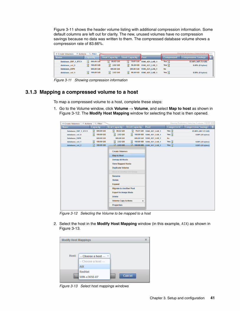
Figure 3-11 shows the header volume listing with additional compression information. Some default columns are left out for clarity. The new, unused volumes have no compression savings because no data was written to them. The compressed database volume shows a compression rate of 83.66%.
Figure 3-11 Showing compression information
3.1.3 Mapping a compressed volume to a host
To map a compressed volume to a host, complete these steps:
1. Go to the Volume window, click Volume → Volume, and select Map to host as shown in Figure 3-12. The Modify Host Mapping window for selecting the host is then opened.
Figure 3-12 Selecting the Volume to be mapped to a host
2. Select the host in the Modify Host Mapping window (in this example, AIX) as shown in Figure 3-13.
Figure 3-13 Select host mappings windows
Chapter 3. Setup and configuration 41

3. After selecting the host, the next Modify Host Mapping window shows all mapped volumes of the host and all unmapped volumes, as seen in Figure 3-14. The previously selected volume is highlighted. You can alter your host mapping in this window. Select Map Volumes to apply the new, or changed host mapping.
Figure 3-14 Modify host mappings window
4. Figure 3-15 shows the message on completing the task. You can copy and paste the commands used to create the volumes and use them as a template for command-line volume creation.
Figure 3-15 Host mapping completed message
42 Accelerate with IBM FlashSystem V840 Compression

This volume can now be used by the host AIX.
Mapping a volume to a host using the CLIYou can use the CLI command mkvdiskhostmap to create compressed volumes. The GUI output shown in Figure 3-15 on page 42 lists the command used for creating a volume. You can use this information as a template for creating volumes using the CLI.
Example 3-2 shows the creation of a volume based on Figure 3-15. This example creates the host mapping for the host AIX of volume database_vol_0.
Example 3-2 Creating a volume using the CLI
IBM_2145:V840_AC1:superuser>svctask mkvdiskhostmap -force -host AIX -scsi 2 database_vol_0Virtual Disk to Host map, id [2], successfully created
Table 3-1 shows the parameters, the values used in the example, and a short description of those parameters.
Table 3-3 Description of the used mkvdiskhostmap parameters
3.2 Host configuration best practices
FlashSystem V840 supports IBM and non-IBM hosts. Therefore, you can consolidate storage capacity and workloads for open-systems hosts into a single storage pool. The storage pool can then be managed from a central point on the storage area network (SAN).
Check the IBM System Storage® Interoperation Center (SSIC) to get the latest information about supported operating systems, hosts, switches, and so on:
http://www.ibm.com/systems/support/storage/ssic/interoperability.wss
FlashSystem V840 can be configured to use Fibre Channel (FC), iSCSI, or Fibre Channel over Ethernet (FCoE) host attachment.
Hosts that use the Fibre Channel connections are attached to the FlashSystem V840 either directly or through a switched Fibre Channel fabric.
Parameter Value Description
-force N/A Allows multiple volume-to-host assignments, which are not normally allowed.
-host AIX Specifies the host to map the volume to, either by ID or by name.
-scsi 2 Specifies the Small Computer System Interface (SCSI) logical unit number (LUN) ID to assign to this volume on the specific host. The scsi_num_arg parameter contains the SCSI LUN ID that is assigned to the volume on the host for all I/O groups that provide access to the volume. You must check your host system for the next available SCSI LUN ID on the host bus adapter (HBA). If you do not specify the -scsi parameter, the next available SCSI LUN ID in each I/O group that provides access is provided to the host.This parameter is optional. Make sure that the value is not used by another FlashSystem V840 volume mapped to the host.
database_vol_0 N/A Specifies the name of the volume that you want to map to the host, either by ID or by name. This must be the last parameter of the command.
Chapter 3. Setup and configuration 43

You can get detailed information about host attachment for different operating systems in the IBM Knowledge Center for FlashSystem V840:
http://www.ibm.com/support/knowledgecenter/ST2HTZ/landing/Flashsystem_V840.htm
This link displays the IBM FlashSystem V840 welcome page and includes all versions of FlashSystem V840.
Select IBM FlashSystem V840 Version 1.3.0. In the section Configuring → Host attachment, you find information about hosts that use FC, iSCSI, or FCoE connections. Click a hosts connection and the list of different hosts, or operating systems is shown. You will find detailed information below these entries.
FlashSystem V840 works most efficiently when data is aligned to 4 K byte blocks. Some operating systems do not automatically align blocks to the 4 KB block boundary. Details about alignment can be found in Implementing IBM FlashSystem 840, SG24-8189, sections 5.3.5 FlashSystem 840 and Microsoft Windows client hosts, and 5.4.3 Linux configuration file multipath.conf example, Creating a Linux partition.
3.2.1 AIX host attachment
Use the Subsystem Device Driver Path Control Module (SDDPCM) for AIX with AIX hosts. SDDPCM manages the paths to provide:
� High availability and load balancing of storage I/O
� Automatic path-failover protection
� Concurrent download of Licensed Internal Code
� Prevention of a single-point-failure caused by the host bus adapter, Fibre Channel cable, Ethernet cable, or host-interface adapter on supported storage
During testing while writing this document, the team used these settings:
� AIX LUN parameters:
– qdepth = 256– max transfer = 0x40000– load balancing = round_robin
� 32 LUNs per AIX host
These two commands were used to optimize the performance:
� mount -o noatime,remount /
This command turns off access-time updates. Using the noatime parameter can improve performance on file systems where many files are read frequently and seldom updated. If you use the option, the last access time for a file cannot be determined.
� schedo -o proc_disk_stats=0
This command manages the processor scheduler. The value of 0 disables the process scope disk statistics. Disabling process scope disk statistics improves performance when you do not want these statistics.
44 Accelerate with IBM FlashSystem V840 Compression

Chapter 4. Operations and analysis
This chapter includes the following sections:
� FlashSystem V840 software stack� Performance monitoring� Using synthetic workloads with Real-time Compression� FlashSystem V840 with RtC compared with disk� Analysis and verification� Converting fully allocated volumes
4
© Copyright IBM Corp. 2015. All rights reserved. 45
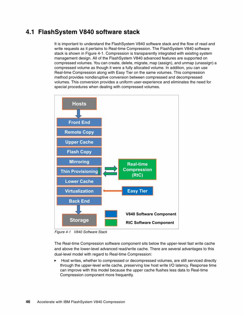
4.1 FlashSystem V840 software stack
It is important to understand the FlashSystem V840 software stack and the flow of read and write requests as it pertains to Real-time Compression. The FlashSystem V840 software stack is shown in Figure 4-1. Compression is transparently integrated with existing system management design. All of the FlashSystem V840 advanced features are supported on compressed volumes. You can create, delete, migrate, map (assign), and unmap (unassign) a compressed volume as though it were a fully allocated volume. In addition, you can use Real-time Compression along with Easy Tier on the same volumes. This compression method provides nondisruptive conversion between compressed and decompressed volumes. This conversion provides a uniform user-experience and eliminates the need for special procedures when dealing with compressed volumes.
Figure 4-1 V840 Software Stack
The Real-time Compression software component sits below the upper-level fast write cache and above the lower-level advanced read/write cache. There are several advantages to this dual-level model with regard to Real-time Compression:
� Host writes, whether to compressed or decompressed volumes, are still serviced directly through the upper-level write cache, preserving low host write I/O latency. Response time can improve with this model because the upper cache flushes less data to Real-time Compression component more frequently.
Hosts
Front End
Remote Copy
Upper Cache
Flash Copy
Mirroring
Thin Provisioning
Lower Cache
Virtualization
Back End
Storage
Real-time Compression
(RtC)
Easy Tier
V840 Software Component
RtC Software Component
46 Accelerate with IBM FlashSystem V840 Compression

� The performance of the destaging of compressed write I/Os to storage is improved because these I/Os are now destaged through the advanced lower-level cache, as opposed to directly to storage.
� The existence of a lower-level write cache below the Real-time Compression component in the software stack allows for the coalescing of compressed writes. This results in a reduction in back-end I/Os due to the ability to perform full-stride writes for compressed data.
� The existence of a lower-level read cache below the Real-time Compression component in the software stack allows the temporal locality nature of Real-time Compression to benefit from pre-fetching from the backend storage.
� The main (lower level) cache stores compressed data for compressed volumes, increasing the effective size of the lower-level cache.
4.1.1 Data write flow
When a host sends write requests to FlashSystem V840, they reach the upper cache layer. The host is immediately sent an acknowledgment of its I/Os.
When the upper cache layer destages to the Real-time Compression component, the I/Os are sent to the thin-provisioning layer. They are then sent to the Real-time Compression component to be compressed before going to the lower-level cache. The metadata that holds the index of the compressed volume is updated if needed, and is compressed as well.
4.1.2 Data read flow
When a host sends a read request to the FlashSystem V840 Controller for compressed data, it is forwarded directly to the Real-time Compression (RtC) component:
� If the RtC component contains the requested data, the FlashSystem V840 Controller cache replies to the host with the requested data without having to read the data from the lower-level cache or disk.
� If the RtC component does not contain the requested data, the request is forwarded to the FlashSystem V840 Controller lower-level cache.
� If the lower-level cache contains the requested data, it is sent up the stack and returned to the host without accessing the storage.
� If the lower-level cache does not contain the requested data, it sends a read request to the storage for the requested data.
4.2 Performance monitoring
This section covers several performance monitoring techniques using Real-time performance monitoring and a brief topic on IBM Tivoli® Storage Productivity Center.
4.2.1 Real-time performance monitoring
Real-time performance statistics provide short-term status information for the FlashSystem V840. The statistics are shown as graphs in the management graphical user interface (GUI) or can be viewed from the command-line interface (CLI). With system-level statistics, you can quickly view the CPU utilization and the bandwidth of volumes, interfaces, and MDisks. Each
Chapter 4. Operations and analysis 47

graph displays the current bandwidth in either megabytes per second (MBps) or I/O operations per second (IOPS), and a view of bandwidth over time. Each node collects various performance statistics, mostly at 5-second intervals, and the statistics that are available from the config node in a clustered environment. This information can help you determine the performance effect of a specific node. As with system statistics, node statistics help you to evaluate whether the node is operating within normal performance metrics. Node statistics can also help determine whether the load on the system is balanced across the nodes.
Real-time performance monitoring gathers the following system-level performance statistics:
� CPU utilization� Port utilization and I/O rates� Volume and MDisk I/O rates� Bandwidth� Latency
Real-time performance monitoring with the CLIThe commands lsnodestats and lssystemstats provide by node and total system statistics. See the FlashSystem V840 documentation for setting up access to the CLI. We accessed the system using the user ID superuser and the ssh command.
The lssystemstats command list the same set of statistics that are listed by the lsnodestats command, but representing all nodes in the cluster. The values for these statistics are calculated from the node statistics values in the following way:
� Bandwidth: Sum of bandwidth of all nodes
� Latency: Average latency for the cluster, which is calculated using data from the whole cluster, not an average of the single node values
� IOPS: Total IOPS of all nodes
� CPU percentage: Average CPU percentage of all nodes
Example 4-1 shows the output of the lssystemstats command.
Example 4-1 lssystemstats command output first lines
perfsh9a> ssh [email protected]@9.11.211.192's password:IBM_2145:perfv840b:superuser>lssystemstatsstat_name stat_current stat_peak stat_peak_timecompression_cpu_pc 8 8 141113154501cpu_pc 0 0 141113154501fc_mb 0 0 141113154501fc_io 576 621 141113154136......
For each statistic, the following columns are displayed:
� stat_name: Provides the name of the statistic field� stat_current: The current value of the statistic field� stat_peak: The peak value of the statistic field in the last 5 minutes� stat_peak_time: The time that the peak occurred
Additional information about the fields can be obtained from the CLI. Use the command help lssystemstats to display detailed command information.
48 Accelerate with IBM FlashSystem V840 Compression

Real-time performance monitoring with the GUIThe real-time statistics are also available from the FlashSystem V840 GUI. The performance monitoring window displays 5 minutes worth of statistics. To open the Performance Monitoring window, go to Monitoring → Performance as shown in Figure 4-2.
Figure 4-2 FlashSystem V840 Performance Monitoring menu
Hint: It is possible to set up a sshkey with the user ID so that you can automate collection of the output from a script:
ssh [email protected] -i ./v840key.ppk lssystemstats
Chapter 4. Operations and analysis 49

The Performance Monitoring window, as shown in Figure 4-3, is divided into four sections that provide utilization views for the following resources.
� CPU Utilization� Volumes� Interfaces� MDisks
The Volumes section shows the traffic generated by the host systems to the FlashSystem V840 Volumes. The MDisks sections show the traffic generated by the FlashSystem V840 controller nodes to the FlashSystem V840 enclosures (and to external disk if configured).
The System Statistics and IOPS menus at the top of the window can be used to change what is monitored. The System Statistics menu allows you to display statistics by total system or by individual node. The IOPS menu can be changed to MBps to monitor throughput instead of operations per second.
Figure 4-3 Performance Monitoring window example
50 Accelerate with IBM FlashSystem V840 Compression

You can hover over the statistic name in each section to reveal a ? that you can hover over to get a description for that statistic as shown in Example 4-4. The boxes next to the statistic name can be selected or cleared. If the box is filled in with color, the statistic is being displayed. If the box is outlined, the statistic is not being displayed.
Figure 4-4 Hovering to show statistic description
Hovering over the value below the statistic displays the 5-minute peak value. You can also hover over the points inside the line graphs to display the actual value for that point.
4.2.2 IBM Tivoli Storage Productivity Center
There are ways to collect statistical files from the FlashSystem V840, but processing them is tedious and inefficient. IBM Tivoli Storage Productivity Center automates the data collection process. Tivoli Storage Productivity Center is a supported tool for the FlashSystem V840 to collect and analyze the performance statistics.
Information on the tool can be found on the product website.
http://www.ibm.com/software/products/en/tivostorprodcent
4.3 Using synthetic workloads with Real-time Compression
Results from traditional block and file based benchmark tools will typically not provide results that are representative of a real customer workload. The data patterns might not be compressible or might be unrealistically compressible. The tools often generate truly random I/O patterns that will not take advantage of the sophisticated algorithms used to improve performance and efficiency on workloads that have some degree of temporal locality.
Just as you would not use a tool to measure deduplication efficiency if you could not control for the deduplication rate, tools that do not have access patterns representative of customer applications have limited value when measuring Real-time Compression. With that being the case, synthetic workloads will often be used and this section provides information about what to expect and how to achieve different results.
Synthetic workloads will often show either best case or worst case results when used with Real-time compression. The next sections will show some results from a synthetic driver for
Chapter 4. Operations and analysis 51

best case scenarios (large and small block sequential reads and writes) and worst case scenarios (small block random reads and writes).
4.3.1 General setup guidelines for synthetic workloads
Listed are some general guidelines for system setup with synthetic workloads:
� Use all available host ports� Using zoning and V840 host definitions have four paths per volume� Tune operating system parameters� Define and use 32 or more volumes� Define the number of volumes to be a multiple of the host ports in use� Use a sequential workload at your target operation size and fill the volumes to capacity
In our testing configuration, we used a FlashSystem V840 with eight 16 Gb host ports and an IBM Power 780 that also had eight 16 Gb host ports available. On the FlashSystem V840, we defined four host definitions each with two WWPNs. We zoned each of the two Power 780 ports as specified in the host definition with a port pair on the FlashSystem V840.
We had previously installed the IBM Subsystem Device Driver and after discovering the device, we checked that the number of paths was correct with the command pcmpath query device 5. Example 4-2 shows that device 5 has four paths: Two preferred and two non-preferred. The * indicates a non-preferred path.
Example 4-2 Checking the number of paths for a device
perfsh9a> pcmpath query device 5
DEV#: 5 DEVICE NAME: hdisk5 TYPE: 2145 ALGORITHM: Round RobinSERIAL: 6005076801FE00019000000000000353==========================================================================Path# Adapter/Path Name State Mode Select Errors 0* fscsi16/path0 CLOSE NORMAL 52 0 1 fscsi16/path1 CLOSE NORMAL 5714444 0 2* fscsi24/path2 CLOSE NORMAL 48 0 3 fscsi24/path3 CLOSE NORMAL 5714441 0
The IBM Power 780 was running AIX 7.1.2.15 and we tuned the operating system with the following settings:
� System Settings:
– "noatime" enabled – proc_disk_stats = 0
� Device Settings:
– hdisk algorithm = round_robin– hdisk queue_depth = 256– hdisk max_transfer = 0x100000 (1 MB)
We defined 48 10-Gb compressed volumes. 48 is a multiple of the eight host ports and four host definitions that we defined.
We ran a 4 KB sequential workload with a compression setting that resulted in a ~3:1 compression ratio (67% savings) for 1 hour. This was long enough to fill the defined compressed capacity and to start overwriting what had been written. It is necessary to do this step so that read operations are not requested to address locations with no data. Keep in
52 Accelerate with IBM FlashSystem V840 Compression

mind that compressed volumes are thin provisioned, and if a location has not been written to, a read request to an unwritten location returns empty data. For testing RtC, we want to force RtC to read and expand data that has been written with a known compression ratio.
4.3.2 Sequential workloads
This section details the potential impact on these types of sequential workloads:
� Large block compressible sequential write workload� Large block compressible sequential read workload� Large block non-compressible sequential write workload� Small block compressible sequential write workload� Small block compressible sequential read workload
Large block compressible sequential write workloadFigure 4-5 shows the real-time performance statistics for a large block (128 KB or 256 KB) compressible sequential write workload using a synthetic driver. Without compression, you would expect the write throughput to the volumes to be similar to the throughput to the MDisks. In this case, because the data is being compressed by approximately 3:1, the throughput to the MDisks is approximately 1/3 the throughput that is being sent by the host to the volumes. Real-time Compression is reducing the load on the storage system by compressing the data before writing it to the attached storage (MDisks).
Figure 4-5 Compressible sequential writes MBps
Chapter 4. Operations and analysis 53
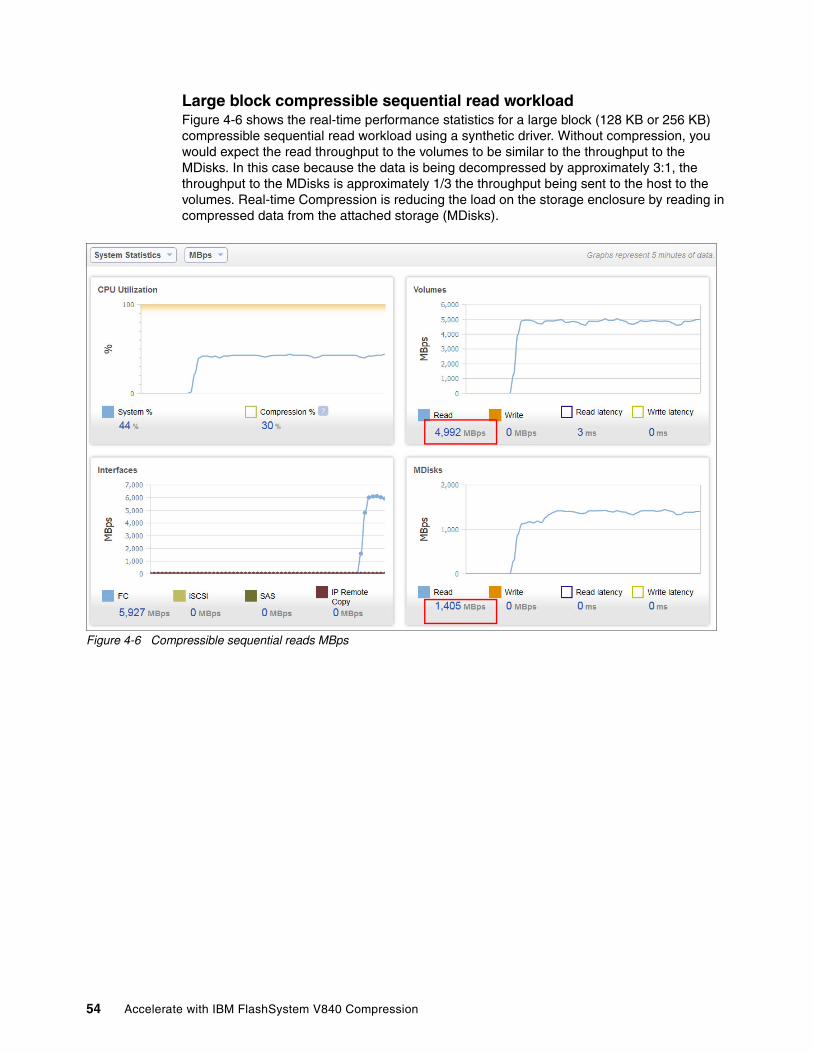
Large block compressible sequential read workloadFigure 4-6 shows the real-time performance statistics for a large block (128 KB or 256 KB) compressible sequential read workload using a synthetic driver. Without compression, you would expect the read throughput to the volumes to be similar to the throughput to the MDisks. In this case because the data is being decompressed by approximately 3:1, the throughput to the MDisks is approximately 1/3 the throughput being sent to the host to the volumes. Real-time Compression is reducing the load on the storage enclosure by reading in compressed data from the attached storage (MDisks).
Figure 4-6 Compressible sequential reads MBps
54 Accelerate with IBM FlashSystem V840 Compression

Large block non-compressible sequential write workloadFigure 4-7 shows the real-time performance statistics for a large block (128 KB or 256 KB) non-compressible sequential write workload using a synthetic driver. The data generating by the synthetic driver is 100% random in nature and no compression reduction is possible. There is an increase in the load on the storage system because the data is not compressible. Non-compressible data (random, previously compressed, encrypted) is not recommended with RtC.
Figure 4-7 Non-compressible sequential writes MBps
Chapter 4. Operations and analysis 55

Small block compressible sequential write workloadFigure 4-8 shows the real-time performance statistics for a small block (4 KB) compressible sequential write workload using a synthetic driver. Without compression, you would expect the write operations per second to the volumes to be similar to the operations per second to the MDisks. In this case, because the small blocks are being coalesced into 32 KB compressed blocks, you would expect to get a reduction in operations from both the compression and the block coalescing. The reduction corresponds to the 3:1 compression ratio of the data (1/3 the original size, or 67% savings) and because you are writing 32 KB blocks instead of 4 KB, you get a reduction of 1/8 (4 KB/32 KB). This reduction is cumulative and you get approximately a 1/24 reduction (1/3 * 1/8) in IOPS. This corresponds to the volume IOPS of 121,777 and the MDisk IOPS of 5266. (121,777/5266 = ~ 23 or 1/23 reduction).
This type of sequential workload is favorable to the RtC algorithm in terms of writing out complete blocks of compressed data.
Figure 4-8 Small block compressible sequential writes
56 Accelerate with IBM FlashSystem V840 Compression

Small block compressible sequential read workloadFigure 4-9 shows the real-time performance statistics for a small block (4 KB) compressible sequential read workload using a synthetic driver. Without compression, you would expect the reads operations per second to the volumes to be similar to the operations per second from the MDisks. In this case, because the small blocks were coalesced into 32 KB compressed blocks and you are reading back in the same order that the blocks were written, you would expect to get a reduction in operations from both the compression and the block coalescing. The reduction corresponds to the 3:1 compression ratio of the data (1/3 the original size, or 67% savings) and because you are reading 32 KB blocks instead of 4 KB, you get a reduction of 1/8 (4 KB/32 KB). This reduction is cumulative and you get approximately a 1/24 reduction (1/3 * 1/8) in IOPS. This corresponds to the volume IOPS of 256,560 and the MDisk IOPS of 12,651. (256,560/12,651 = ~ 20 or 1/20 reduction)
This type of sequential read workload that was preceded by a sequential write workload represents a best case scenario for the RtC algorithm. Nearly all the blocks are read in the same order that they were written. You might get similar random read performance if the random workload had high temporal locality.
Figure 4-9 Small block compressible sequential reads
4.3.3 Random workloads
Completely random workloads do not get any benefit from the sophisticated prefetch algorithms that RtC uses to optimize performance for customer workloads. Most customer workloads have some degree of temporal locality and achieve better results than what is measured with synthetic completely random workloads.
Chapter 4. Operations and analysis 57

Small block compressible random write workloadFigure 4-10 shows point in time performance of a completely random 4 KB small block workload. The performance is lower than the sequential 4 KB workload and there is significantly higher read operations as well. The read operations are metadata operations to update all the changes due to the random write requests.
Figure 4-10 Small block compressible random writes
58 Accelerate with IBM FlashSystem V840 Compression

Small block compressible random read workloadFigure 4-11 shows point in time performance of a completely random 4 KB small block read workload. The performance is lower than the sequential 4 KB read workload and there is not a reduction in read operations. The synthetically random requests do not receive the benefit from the random prefetch that you would get if the requests had some degree of temporal locality.
Figure 4-11 Small block compressible random reads
4.4 FlashSystem V840 with RtC compared with disk
For applications that do not need advanced functionality and require the lowest latency and the highest possible operations per second, FlashSystem 840 is the best choice. If you require advanced functionality and would like to maximize your investment in terms of capacity, and still have substantially increased performance over disk, the FlashSystem V840 is the solution.
This section compares a FlashSystem V840 with twelve 2 TB Flash Modules against a first-generation V7000 with 216 x 150 GB SAS 15 K RPM hard disk drives. The V7000 drives are configured into 26 x RAID 5 7+P groups with eight spares. The FlashSystem V840 (6U) takes up 1/3 of the rack space as compared to the V7000 (nine enclosures X 2U). The same host and synthetic driver are used in both products. The synthetic workload with 100% random data represents a worst case scenario for Real-time Compression. Actual production
Note: For more information about FlashSystem 840, see Implementing IBM FlashSystem 840, SG24-8189.
Chapter 4. Operations and analysis 59

workloads that have compression cache hits (temporal locality / random pre-fetch) can have up to three times the operations per second over the worst case workloads shown.
Even though the workloads are worst case for RtC, the results are still much better than you can achieve with typical disk subsystems. In all the comparisons, the V840 provided sub-millisecond response times at the same operations per second load when compared to the first-generation V7000.
4 KB Random Write ComparisonIn Figure 4-12, the FlashSystem V840 achieved over twice the random 4 KB write operations per second at sub-millisecond response times when compared to the V7000.
Figure 4-12 V7000 / V840 random write comparison
60 Accelerate with IBM FlashSystem V840 Compression

4 KB random 70% reads 30% writes comparisonIn Figure 4-13, the FlashSystem V840 achieved almost double the random mixed 4 KB operations per second at sub-millisecond response times when compared to the V7000.
Figure 4-13 V7000 / V840 70r/30w cache miss comparison
4 KB random read comparisonIn Figure 4-14, the FlashSystem V840 achieved almost double the random read 4 KB operations per second at sub-millisecond response times when compared to the V7000.
Figure 4-14 V7000 / V840 random read comparison
Chapter 4. Operations and analysis 61

4 KB 70% reads 30% writes with 50% cache hit comparisonIn Figure 4-15, the FlashSystem V840 achieved almost 50% more mixed read/write 4 KB operations per second at sub millisecond response times when compared to the V7000.
Figure 4-15 V7000 / V840 70r/30w 50% cache hit comparison
4 KB read with 50% cache hit comparisonIn Figure 4-16, the FlashSystem V840 achieved 4 KB reads with 50% cache hit operations per second at sub-millisecond response times when compared to the V7000 ranging from 3 to 8 ms.
Figure 4-16 V7000 / V840 100% read 50% cache hit comparison
62 Accelerate with IBM FlashSystem V840 Compression

4.5 Analysis and verification
This section expands on interpreting the performance statistics as they concern Real-time Compression. For these interpretations to be accurate, you must be running only the workload that you are analyzing. The performance statistics are system wide and traffic to standard volumes or any other activity will skew the results.
4.3.2, “Sequential workloads” on page 53 looked at the reduction in throughput for large block sequential workloads and the reduction in operation requests for small block sequential workloads. The throughput reduction is based on the compression savings achieved. Table 4-1 shows the correlation between the terms used when referencing compression. For the examples in this paper, we used a setting for the synthetic driver that resulted in data generated that compressed at a ratio of 3:1. This was verified by looking in the FlashSystem V840 GUI at the volume properties that displayed a % Savings of 67%.
Table 4-1 Compression Ratio, Reduction Divisor, % Savings, % Written
The order that data is read or rewritten affects the performance of RtC. If the data is read in the same or similar order, performance is higher. If data is sequentially written, the performance is higher if it is sequentially read or rewritten. If the data is randomly written, then performance is higher if it is read or rewritten in that same order. A different random read or rewrite order, or a sequential read or rewrite, have lower performance. However, as demonstrated in 4.4, “FlashSystem V840 with RtC compared with disk”, the performance is better than most disk systems, regardless of the order the data is read or rewritten.
The next sections will look at workloads with both high and low temporal locality.
4.5.1 Analyzing temporal locality in workloads
When using FlashSystem V840 performance statistics for analyzing RtC, the MBPS ratio of the volumes and the MDisks can provide insight into the temporal locality of the workload. The Volumes MBPS reports the throughput generated by the host systems to the FlashSystem V840 Volumes. The MDisks MBPS reports the traffic generated by the FlashSystem V840 controller nodes to the FlashSystem V840 enclosures after the data has been processed by Real-time Compression.
If the workload has high temporal locality (data is read or rewritten in a similar order that it was written), the ratio of volume MBPS to MDisk MBPS is close to the compression ratio. There is a net reduction in throughput to/from the FlashSystem V840 storage. If the workload has low or no temporal locality, there can be a net increase in throughput to/from the
Compression Ratio Reduction Divisor % Savings (1 - % Written)
% Written(1 - %Savings)
1:1 1 <-> 1/1 0% 100%
1.5:1 1.5 <-> 1/1.5 33% 67%
2:1 2 <-> 1/2 50% 50%
3:1 3 <-> 1/3 67% 33%
4:1 4 <-> 1/4 75% 25%
5:1 5 <-> 1/5 80% 20%
10:1 10 <-> 1/10 90% 10%
Chapter 4. Operations and analysis 63

FlashSystem V840 storage when compared to what is being sent/received by the host systems.
The results in this section are based on an achieved compression ratio of 3:1 or 67% savings. Workloads with higher or lower compression savings have a corresponding higher or lower maximum MBPS reduction.
Small block writes with high temporal localityFigure 4-17 places the IOPS and MBPS sections from the Performance Monitor side by side. This write workload shows high temporal locality. The ratio of Volume MBPS to MDisks MBPS is 464:164 or ~ 3:1. This is close to the achieved compression savings. The IOPS are reduced by an approximate factor of 24: 1/3 for the compression, and 1/8 for coalescing the 4 KB write blocks into 32 KB compressed blocks.
Figure 4-17 4 KB block writes with high temporal locality side by side MBPS / IOPS
64 Accelerate with IBM FlashSystem V840 Compression

Small block reads with high temporal localityFigure 4-18 places the IOPS and MBPS sections from the Performance Monitor side by side. This read workload shows high temporal locality. The ratio of Volume MBPS to MDisks MBPS is 1013:411 or ~ 2.5:1. This is close to the achieved compression savings. The IOPS are reduced by an approximate factor of 20: 1/3 for the compression and 1/8 for coalescing the 4 KB blocks into 32 KB compressed blocks.
Figure 4-18 KB block reads with high temporal locality side by side MBPS / IOPS
Chapter 4. Operations and analysis 65

Small block writes with low temporal localityFigure 4-19 places the IOPS and MBPS sections from the Performance Monitor side by side. This write workload shows low temporal locality. There is a significant read workload as well because the writes are completely random, and the amount of metadata and compressed blocks that need to be update is high. It includes the MDisk read values in the ratio comparison. The ratio of Volume MBPS to MDisks MBPS is 292:183 or ~ 1:1.6. There is more throughput activity to the storage than to the hosts. This workload has low temporal locality. The IOPS are only reduced by an approximate factor of 5.
Figure 4-19 4 KB block writes with low temporal locality side by side MBPS / IOPS
66 Accelerate with IBM FlashSystem V840 Compression

Small block reads with low temporal localityFigure 4-20 places the IOPS and MBPS sections from the Performance Monitor side by side. This read workload shows low temporal locality. The ratio of Volume MBPS to MDisks MBPS is 288:2455 or ~ 1:8.5. There is more throughput activity to the storage than to the hosts. This workload has low temporal locality. There is no reduction in IOPS because the workload has no temporal locality.
Figure 4-20 4 KB block reads with low temporal locality side by side MBPS / IOPS
Chapter 4. Operations and analysis 67
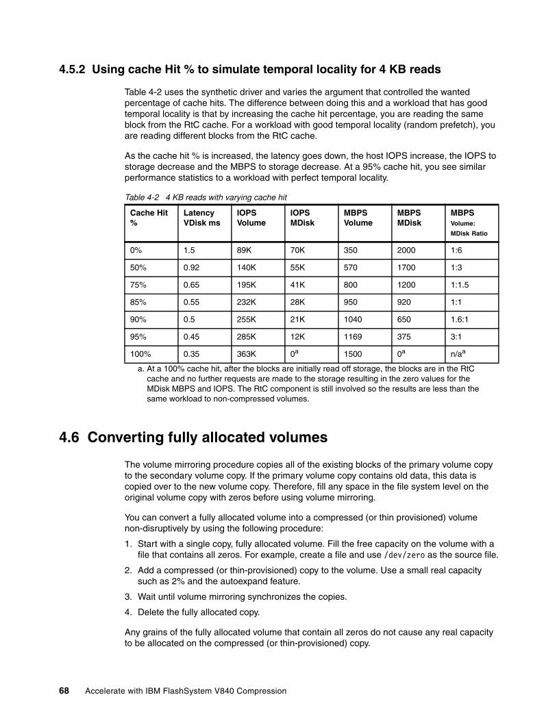
4.5.2 Using cache Hit % to simulate temporal locality for 4 KB reads
Table 4-2 uses the synthetic driver and varies the argument that controlled the wanted percentage of cache hits. The difference between doing this and a workload that has good temporal locality is that by increasing the cache hit percentage, you are reading the same block from the RtC cache. For a workload with good temporal locality (random prefetch), you are reading different blocks from the RtC cache.
As the cache hit % is increased, the latency goes down, the host IOPS increase, the IOPS to storage decrease and the MBPS to storage decrease. At a 95% cache hit, you see similar performance statistics to a workload with perfect temporal locality.
Table 4-2 4 KB reads with varying cache hit
4.6 Converting fully allocated volumes
The volume mirroring procedure copies all of the existing blocks of the primary volume copy to the secondary volume copy. If the primary volume copy contains old data, this data is copied over to the new volume copy. Therefore, fill any space in the file system level on the original volume copy with zeros before using volume mirroring.
You can convert a fully allocated volume into a compressed (or thin provisioned) volume non-disruptively by using the following procedure:
1. Start with a single copy, fully allocated volume. Fill the free capacity on the volume with a file that contains all zeros. For example, create a file and use /dev/zero as the source file.
2. Add a compressed (or thin-provisioned) copy to the volume. Use a small real capacity such as 2% and the autoexpand feature.
3. Wait until volume mirroring synchronizes the copies.
4. Delete the fully allocated copy.
Any grains of the fully allocated volume that contain all zeros do not cause any real capacity to be allocated on the compressed (or thin-provisioned) copy.
Cache Hit %
Latency VDisk ms
IOPS Volume
IOPS MDisk
MBPS Volume
MBPS MDisk
MBPS Volume:
MDisk Ratio
0% 1.5 89K 70K 350 2000 1:6
50% 0.92 140K 55K 570 1700 1:3
75% 0.65 195K 41K 800 1200 1:1.5
85% 0.55 232K 28K 950 920 1:1
90% 0.5 255K 21K 1040 650 1.6:1
95% 0.45 285K 12K 1169 375 3:1
100% 0.35 363K 0a
a. At a 100% cache hit, after the blocks are initially read off storage, the blocks are in the RtC cache and no further requests are made to the storage resulting in the zero values for the MDisk MBPS and IOPS. The RtC component is still involved so the results are less than the same workload to non-compressed volumes.
1500 0a n/aa
68 Accelerate with IBM FlashSystem V840 Compression

Chapter 5. Hints and tips
This chapter describes how to find information for IBM FlashSystem V840 on following topics:
� Installing FlashSystem V840
� Servicing FlashSystem V840
� FlashSystem V840 Health status check
This chapter gives hints on benchmarking tools and on troubleshooting.
5
© Copyright IBM Corp. 2015. All rights reserved. 69

5.1 Hints
This section contains hints on finding information about IBM FlashSystem V840.
5.1.1 IBM FlashSystem V840 installation
FlashSystem V840 is usually installed by IBM. You can get detailed information about installing FlashSystem V840 in the IBM Knowledge Center for FlashSystem V840:
http://www.ibm.com/support/knowledgecenter/ST2HTZ/landing/Flashsystem_V840.htm
This is the IBM FlashSystem V840 welcome page and includes all versions of FlashSystem V840. Every version of code has different sections:
� Product overview
Overviews are provided to give information about the web application and important concepts necessary to use the FlashSystem V840, including descriptions of the pre-installation and configuration tasks.
� Planning
Use this information to plan the configuration of FlashSystem V840.
� Installing
Information on the installation and initial setup of FlashSystem V840, including scale up/scale out.
� Configuring
Configure host connections, nodes, clusters, users, disk controllers, and error logs. Use and define configuration rules for various components of your SAN such as host bus adapters (HBAs), nodes, switches, disk controllers, and Fibre Channel cables.
� Administering
You can use the management GUI or the command-line interface (CLI) to administer your system.
� Monitoring
Monitoring the FlashSystem V840 system, software, and hardware components helps to verify that tasks have completed successfully. If a problem occurs during a lengthy operation, monitoring the task ensures quick detection and resolution.
� Upgrading
The system upgrade process involves the upgrading of your entire FlashSystem V840 environment.
� Troubleshooting
Review the troubleshooting procedures to diagnose and resolve problems.
� Reference
Reference topics provide information about the CIM Agent development, logs and traces, and other topics for FlashSystem V840.
� Glossary
This glossary provides terms and definitions for the FlashSystem V840 software and products.
You can use these sections to set up and configure FlashSystem V840.
70 Accelerate with IBM FlashSystem V840 Compression

5.1.2 Servicing FlashSystem V840
FlashSystem V840 provides a number of user interfaces to troubleshoot, recover, and maintain your system. The interfaces provide various sets of facilities to help resolve situations that you might encounter:
� Use the management GUI to monitor and maintain the configuration of storage that is associated with your clustered systems.
The management GUI is a browser-based GUI for configuring and managing all aspects of your system. It provides extensive facilities to help troubleshoot and correct problems.
� Complete service procedures from the service assistant.
The service assistant provides detailed status and error summaries
Use the service assistant only if you cannot access the system using the GUI or the CLI, or if a recommended action directs you to use the service assistant.
� Use the command-line interface (CLI) to manage your system.
The service CLI is intended for use by advanced users who are confident at using a command-line interface.
For more instruction, see the IBM Knowledge Center for FlashSystem V840 at:
http://www.ibm.com/support/knowledgecenter/ST2HTZ/landing/Flashsystem_V840.htm
5.1.3 System check
Before investigating performance problems, make sure that the health status of the FlashSystem V840 environment is good. You must look at these components:
� FlashSystem V840 storage enclosure
You can use the FlashSystem V840 storage enclosure GUI to access the event messages. Click Monitoring → Events and check for errors. You can also use the CLI command lseventlog. Make sure that there are no errors.
� FlashSystem V840 control nodes
You can use the FlashSystem V840 controller node GUI to access the event messages. Click Monitoring → Events and check for errors. You can also use the CLI command lseventlog. Make sure that there are no errors.
� FlashSystem V840 internal connect
FlashSystem V840 can be deployed in a direct attached mode when you use one FlashSystem. When you combine two or moreFlashSystem V840s to a scaled system, the controller nodes and the FlashSystem V840 storage enclosures are connected as an internal fabric using switches. Make sure that cabling is done according to the FlashSystem V840 IBM Knowledge Center as mentioned in 5.1.1, “IBM FlashSystem V840 installation” on page 70. It Is a recommend practice to set the switch buffer to buffer credits value to 80 on every port.
Make sure that the two interlink connections are masked correctly. This ensures that the interlink traffic, like cache mirroring, uses the fastest route to the other node. Use the following command to set the appropriate mask:
svctask chsystem -localfcportmask
Chapter 5. Hints and tips 71

Example 5-1 shows the command to set the local port mask on FlashSystem V840 with 8 GB direct Fibre Channel connections.
Example 5-1 Setting the local port mask on a FlashSystem V840 with 8 GB connections only
> svctask chsystem -localfcportmask 100000010000
This example assumes that ports 5 of each node are connected together, and ports 12 are connected together. Example 5-2 shows the CLI command lsfabric to verify the settings.
� FlashSystem V840 connections with the host
Make sure that cabling is done according to the FlashSystem V840 IBM Knowledge Center as mentioned in 5.1.1, “IBM FlashSystem V840 installation” on page 70. It is a recommended practice to set the switch buffer to buffer credits value to 80 on every switch port connected to the host and to the FlashSystem V840. Always check for errors on the switch.
� Host configuration
FlashSystem V840 works best when data is aligned to 4 K byte blocks. Some operating systems do not automatically align blocks to the 4 KB block boundary. For more information about alignment, see Implementing IBM FlashSystem 840, SG24-8189, sections 5.3.5 FlashSystem 840 and Microsoft Windows client hosts, and 5.4.3 Linux configuration file multipath.conf example; Creating a Linux partition.
Make sure that all host parameters and configurations are set according to the IBM Knowledge Center for FlashSystem V840:
http://www.ibm.com/support/knowledgecenter/ST2HTZ/landing/Flashsystem_V840.htm
Click Configuring → Host attachment and select your system. You will get information about correct setup for multipathing and other configuration for all supported host systems.
Check the internal interconnectYou can check the internal interconnect using the CLI commands lsfrabric and lsfabric840 on the control enclosure and the storage enclosure, respectively.
The following examples show the connections of a direct connected building block with three 8 GB FC cards. Each card has 4 FC ports.
Example 5-2 shows the lsfabric command of the FlashSystem V840 controller enclosure. The parameter -cluster is used to list only the connections between the cluster nodes. The active local ports 5 and 12 are highlighted in bold and colored in blue. The other possible connections on ports 3 and 4 are a connection using the host attachment switch. These connections are disabled due to the command used in Example 5-1.
Example 5-2 FlashSystem V840 control enclosure fabric information
IBM_2145:V840_AC1:superuser>lsfabric -cluster V840_AC1remote_wwpn remote_nportid id node_name local_wwpn local_port local_nportid state name cluster_name type500507680C1300B5 1E0800 1 node_75AAMD0 500507680C13009A 3 1E0A00 blocked node_75AALB0 V840_AC1 node500507680C1300B5 1E0800 1 node_75AAMD0 500507680C14009A 4 1E0D00 blocked node_75AALB0 V840_AC1 node500507680C1400B5 1E0E00 1 node_75AAMD0 500507680C13009A 3 1E0A00 blocked node_75AALB0 V840_AC1 node500507680C1400B5 1E0E00 1 node_75AAMD0 500507680C14009A 4 1E0D00 blocked node_75AALB0 V840_AC1 node500507680C2100B5 AB0100 1 node_75AAMD0 500507680C21009A 5 AB0200 active node_75AALB0 V840_AC1 node500507680C5400B5 AB0100 1 node_75AAMD0 500507680C54009A 12 AB0200 active node_75AALB0 V840_AC1 node500507680C13009A 1E0A00 2 node_75AALB0 500507680C1300B5 3 1E0800 blocked node_75AAMD0 V840_AC1 node500507680C13009A 1E0A00 2 node_75AALB0 500507680C1400B5 4 1E0E00 blocked node_75AAMD0 V840_AC1 node500507680C14009A 1E0D00 2 node_75AALB0 500507680C1300B5 3 1E0800 blocked node_75AAMD0 V840_AC1 node500507680C14009A 1E0D00 2 node_75AALB0 500507680C1400B5 4 1E0E00 blocked node_75AAMD0 V840_AC1 node500507680C21009A AB0200 2 node_75AALB0 500507680C2100B5 5 AB0100 active node_75AAMD0 V840_AC1 node500507680C54009A AB0200 2 node_75AALB0 500507680C5400B5 12 AB0100 active node_75AAMD0 V840_AC1 node
72 Accelerate with IBM FlashSystem V840 Compression

Example 5-3 shows the lsfabric command of the FlashSystem V840 controller enclosure. The parameter -controller is used to list only the connections between the cluster nodes and the specified storage enclosure. The connections are colored in blue, magenta, red, and black to show the connections to the FlashSystem V840 storage enclosure. FlashSystem V840 storage enclosure has four FC cards with four ports each. In total, 10 of the possible 16 ports are used when using direct connections. Each color represents the ports of an FC card as shown in Example 5-4.
Example 5-3 FlashSystem V840 control enclosure fabric information for attached storage enclosure
IBM_2145:V840_AC1:superuser>lsfabric -controller V840_AE1remote_wwpn remote_nportid id node_name local_wwpn local_port local_nportid state name cluster_name type500507605EBFF271 AB0200 1 node_75AAMD0 500507680C23009A 7 AB0100 active V840_AE1 controller500507605EBFF251 AB0200 1 node_75AAMD0 500507680C22009A 6 AB0100 active V840_AE1 controller500507605EBFF253 AB0200 1 node_75AAMD0 500507680C53009A 11 AB0100 active V840_AE1 controller500507605EBFF252 AB0200 1 node_75AAMD0 500507680C52009A 10 AB0100 active V840_AE1 controller500507605EBFF272 AB0200 1 node_75AAMD0 500507680C24009A 8 AB0100 active V840_AE1 controller500507605EBFF261 AB0200 2 node_75AALB0 500507680C2200B5 6 AB0100 active V840_AE1 controller500507605EBFF241 AB0200 2 node_75AALB0 500507680C5200B5 10 AB0100 active V840_AE1 controller500507605EBFF262 AB0200 2 node_75AALB0 500507680C2300B5 7 AB0100 active V840_AE1 controller500507605EBFF242 AB0200 2 node_75AALB0 500507680C5300B5 11 AB0100 active V840_AE1 controller500507605EBFF263 AB0200 2 node_75AALB0 500507680C2400B5 8 AB0100 active V840_AE1 controller
Example 5-4 shows the lsfabric840 command of the FlashSystem V840 storage enclosure.
Example 5-4 FlashSystem V840 storage enclosure fabric information
IBM_Flashsystem:V840_AE1:superuser>lsfabric840remote_uid local_uid canister_id adapter_id port_id node_id node_name type500507680C53009A 500507605EBFF253 1 2 3 1 V840_AE1_LEFT fc500507680C52009A 500507605EBFF252 1 2 2 1 V840_AE1_LEFT fc500507680C22009A 500507605EBFF251 1 2 1 1 V840_AE1_LEFT fc500507680C23009A 500507605EBFF271 2 2 1 3 V840_AE1_RIGHT fc500507680C24009A 500507605EBFF272 2 2 2 3 V840_AE1_RIGHT fc500507680C5300B5 500507605EBFF242 1 1 2 1 V840_AE1_LEFT fc500507680C5200B5 500507605EBFF241 1 1 1 1 V840_AE1_LEFT fc500507680C2300B5 500507605EBFF262 2 1 2 3 V840_AE1_RIGHT fc500507680C2400B5 500507605EBFF263 2 1 3 3 V840_AE1_RIGHT fc500507680C2200B5 500507605EBFF261 2 1 1 3 V840_AE1_RIGHT fc
5.1.4 Benchmark tools
You can use your actual application workload to test the Real-time Compression ratio and performance with FlashSystem V840. If the data is already managed by FlashSystem V840 or can be added to FlashSystem V840, you just need to add a compressed mirror to your data. For more information, see 4.6, “Converting fully allocated volumes” on page 68.
You can also use a benchmarking tool to benchmark compressed performance. First use Comprestimator as described in 2.4, “Comprestimator” on page 25, and then use a benchmarking tool. Free testing tools available include IOmeter, and VDBench. The current version of VDBench has support for configured compression ratios.
These tools do not cover the amount of temporal locality. The worst case is no correlation between the write and read I/O patterns. For example, the random reads of a benchmarking tool might read blocks with no correlation to the writes. Then, the system must read and decompress a 32 KB block from the storage device for every 4 KB host read. This is a worst case scenario and shows that traditional random IO benchmark does not consider the temporal locality of your actual application workload.
Chapter 5. Hints and tips 73

5.2 Troubleshooting
Performance problems can be caused by many different sources. If you encounter problems, first check all points that are mentioned in 5.1.3, “System check” on page 71. Then, follow the instructions in the listed in the Troubleshooting section of IBM Knowledge Center for FlashSystem V840:
http://www.ibm.com/support/knowledgecenter/ST2HTZ/landing/Flashsystem_V840.htm
5.2.1 Performance bottlenecks
When you use compression, monitor overall performance and CPU utilization to ensure that other system functions have adequate bandwidth.
To view performance statistics that are related to compression, select Monitoring → Performance on the FlashSystem V840 controller nodes GUI and then select Compression% on the CPU Utilization graph.
Figure 5-1 show a CPU utilization of 8% for compression. FlashSystem V840 uses two multi-core CPUs. One CPU power is used for compression and one CPU power is used for all other tasks.
Figure 5-1 Monitoring Performance and compression percentage
Note: Random IO benchmark tools do not consider the temporal locality of an actual application workload. They will not show the performance that you will get with Real-time compression and actual application workloads.
74 Accelerate with IBM FlashSystem V840 Compression

Example 5-5 shows the CPU statistics using the CLI command.
Example 5-5 CPU statistics using the CLI (only the first three lines are shown)
>svcinfo lsnodestatsnode_id node_name stat_name stat_current stat_peak stat_peak_time1 node_75AAD0 compression_cpu_pc 8 8 1411132203011 node_75AAD0 cpu_pc 30 30 141113220301...
You can use IBM Tivoli Storage Productivity Center or other tools like Quick performance overview (qperf) that you can download from the IBM Techdocs Library (document TD105947) at:
http://www.ibm.com/support/techdocs
Use these tools to check the usage of the Fibre Channel ports, volumes, managed disks, and so on. Make sure that the resources are used in a balanced way. For example, the load of compressed volumes should be spread evenly over all controller nodes.
Check the storage networkAlways make sure that the storage network is correctly set up. Use the information from 5.1.3, “System check” on page 71 to check for correct cabling.
Always check the switch for errors and correct settings.
Note: It Is a recommend practice to set the switch buffer to buffer credits value to 80 on every switch port.
Chapter 5. Hints and tips 75

76 Accelerate with IBM FlashSystem V840 Compression
Related publications
The publications listed in this section are considered particularly suitable for a more detailed discussion of the topics covered in this paper.
IBM Redbooks
The following IBM Redbooks publications provide additional information about the topic in this document. Note that some publications referenced in this list might be available in softcopy only.
� IBM FlashSystem V840, TIPS1158
� IBM SAN Volume Controller 2145-DH8 Introduction and Implementation, SG24-8229
� Implementing the IBM System Storage SAN Volume Controller V7.2, SG24-7933
� Implementing IBM Easy Tier with IBM Real-time Compression, TIPS1072
� Real-time Compression in SAN Volume Controller and Storwize V7000, REDP-4859
You can search for, view, download or order these documents and other Redbooks, Redpapers, Web Docs, draft and additional materials, at the following website:
ibm.com/redbooks
Online resources
These websites are also relevant as further information sources:
� IBM FlashSystem V840 Knowledge Center
http://www.ibm.com/support/knowledgecenter/ST2HTZ
� IBM FlashSystem family product page
http://www.ibm.com/storage/flash
� IBM System Storage Interoperation Center (SSIC)
http://www.ibm.com/systems/support/storage/ssic/interoperability.ws
Help from IBM
IBM Support and downloads
ibm.com/support
IBM Global Services
ibm.com/services
© Copyright IBM Corp. 2015. All rights reserved. 77

78 Accelerate with IBM FlashSystem V840 Compression


®
REDP-5147-00
INTERNATIONAL TECHNICALSUPPORTORGANIZATION
BUILDING TECHNICAL INFORMATION BASED ON PRACTICAL EXPERIENCE
IBM Redbooks are developed by the IBM International Technical Support Organization. Experts from IBM, Customers and Partners from around the world create timely technical information based on realistic scenarios. Specific recommendations are provided to help you implement IT solutions more effectively in your environment.
For more information:ibm.com/redbooks
Redpaper™
Accelerate with IBM FlashSystem V840 Compression
Effectively implement Real-time Compression in business environments
Increase the effective capacity of flash storage
Tune and troubleshoot your compression environment
This IBM Redpaper publication describes how to effectively implement IBM FlashSystem V840 (V840) and IBM Real-time Compression (RtC) and capacity savings. It walks you through planning, setup, configuration, operations, and performance guidance to use FlashSystem V840 performance.
It covers the following topics:
� “Overview and introductory concepts” discusses introductory concepts of IBM Real-time Compression, FlashSystem V840, and business benefits gained from implementing compression.
� “Planning your environment” describes candidate data sets and workloads for compression, and general guidelines. Also included is a topic on installing and using the Comprestimator utility to estimate expected compression rate for FlashSystem V840.
� “Setup and configuration” walks you through the process of creating and mapping compressed volumes for host environments.
� “Operations and analysis” discusses the V840 software stack, performance monitoring, using synthetic workloads with RtC, V840 with RtC compared with disk, and a topic on analysis and verification.
� “Hints and tips” documents how to find information for installing, servicing, and health status check information for FlashSystem V840. Also provided are hints on benchmarking tools and troubleshooting.
This publication is intended for use by storage administrators, who are responsible for the performance and growth of the IT storage infrastructure, and anyone who wants to learn more about effectively implementing FlashSystem V840 and IBM Real-time Compression.
Back cover