AC Servomotors/Servo Drives 1S-series with Built-in ... · 12 Troubleshooting 12 - 4 AC...
44
12 - 1 12 AC Servomotors/Servo Drives 1S-series with Built-in EtherCAT® Communications User’s Manual (I586) This section explains the items to check when problems occur, and troubleshooting by the use of error displays or operation state. 12-1 Actions for Problems . . . . . . . . . . . . . . . . . . . . . . . . . . . . . . . . . . . . . . . . . . 12-2 12-1-1 Preliminary Checks When a Problem Occurs . . . . . . . . . . . . . . . . . . . . . . . 12-2 12-1-2 Precautions When a Problem Occurs . . . . . . . . . . . . . . . . . . . . . . . . . . . . . 12-3 12-1-3 Replacing the Servomotor or Servo Drive . . . . . . . . . . . . . . . . . . . . . . . . . . 12-4 12-2 Warnings . . . . . . . . . . . . . . . . . . . . . . . . . . . . . . . . . . . . . . . . . . . . . . . . . . . . 12-6 12-2-1 Related Objects . . . . . . . . . . . . . . . . . . . . . . . . . . . . . . . . . . . . . . . . . . . . . . 12-6 12-2-2 Warning List . . . . . . . . . . . . . . . . . . . . . . . . . . . . . . . . . . . . . . . . . . . . . . . . . 12-8 12-3 Errors . . . . . . . . . . . . . . . . . . . . . . . . . . . . . . . . . . . . . . . . . . . . . . . . . . . . . 12-10 12-3-1 Error List . . . . . . . . . . . . . . . . . . . . . . . . . . . . . . . . . . . . . . . . . . . . . . . . . . . 12-10 12-3-2 Deceleration Stop Operation at Errors . . . . . . . . . . . . . . . . . . . . . . . . . . . . 12-12 12-4 Information . . . . . . . . . . . . . . . . . . . . . . . . . . . . . . . . . . . . . . . . . . . . . . . . . 12-13 12-4-1 Related Objects . . . . . . . . . . . . . . . . . . . . . . . . . . . . . . . . . . . . . . . . . . . . . 12-13 12-4-2 Information List . . . . . . . . . . . . . . . . . . . . . . . . . . . . . . . . . . . . . . . . . . . . . . 12-13 12-5 Troubleshooting . . . . . . . . . . . . . . . . . . . . . . . . . . . . . . . . . . . . . . . . . . . . . 12-14 12-5-1 Troubleshooting Using Error Displays . . . . . . . . . . . . . . . . . . . . . . . . . . . . 12-14 12-5-2 Troubleshooting Using AL Status Codes . . . . . . . . . . . . . . . . . . . . . . . . . . 12-34 12-5-3 Troubleshooting Using the Operation State . . . . . . . . . . . . . . . . . . . . . . . . 12-38 Troubleshooting
Transcript of AC Servomotors/Servo Drives 1S-series with Built-in ... · 12 Troubleshooting 12 - 4 AC...

12 - 1
12
AC Servomotors/Servo Drives 1S-series with Built-in EtherCAT® Communications User’s Manual (I586)
This section explains the items to check when problems occur, and troubleshooting by the use of error displays or operation state.
12-1 Actions for Problems . . . . . . . . . . . . . . . . . . . . . . . . . . . . . . . . . . . . . . . . . . 12-212-1-1 Preliminary Checks When a Problem Occurs . . . . . . . . . . . . . . . . . . . . . . . 12-212-1-2 Precautions When a Problem Occurs . . . . . . . . . . . . . . . . . . . . . . . . . . . . . 12-312-1-3 Replacing the Servomotor or Servo Drive . . . . . . . . . . . . . . . . . . . . . . . . . . 12-4
12-2 Warnings . . . . . . . . . . . . . . . . . . . . . . . . . . . . . . . . . . . . . . . . . . . . . . . . . . . . 12-612-2-1 Related Objects . . . . . . . . . . . . . . . . . . . . . . . . . . . . . . . . . . . . . . . . . . . . . . 12-612-2-2 Warning List . . . . . . . . . . . . . . . . . . . . . . . . . . . . . . . . . . . . . . . . . . . . . . . . . 12-8
12-3 Errors . . . . . . . . . . . . . . . . . . . . . . . . . . . . . . . . . . . . . . . . . . . . . . . . . . . . . 12-1012-3-1 Error List . . . . . . . . . . . . . . . . . . . . . . . . . . . . . . . . . . . . . . . . . . . . . . . . . . . 12-1012-3-2 Deceleration Stop Operation at Errors . . . . . . . . . . . . . . . . . . . . . . . . . . . . 12-12
12-4 Information . . . . . . . . . . . . . . . . . . . . . . . . . . . . . . . . . . . . . . . . . . . . . . . . . 12-1312-4-1 Related Objects . . . . . . . . . . . . . . . . . . . . . . . . . . . . . . . . . . . . . . . . . . . . . 12-1312-4-2 Information List . . . . . . . . . . . . . . . . . . . . . . . . . . . . . . . . . . . . . . . . . . . . . . 12-13
12-5 Troubleshooting . . . . . . . . . . . . . . . . . . . . . . . . . . . . . . . . . . . . . . . . . . . . . 12-1412-5-1 Troubleshooting Using Error Displays . . . . . . . . . . . . . . . . . . . . . . . . . . . . 12-1412-5-2 Troubleshooting Using AL Status Codes . . . . . . . . . . . . . . . . . . . . . . . . . . 12-3412-5-3 Troubleshooting Using the Operation State . . . . . . . . . . . . . . . . . . . . . . . . 12-38
Troubleshooting
12 Troubleshooting
12 - 2 AC Servomotors/Servo Drives 1S-series with Built-in EtherCAT® Communications User’s Manual (I586)
12-1 Actions for Problems
If any problems should occur, take the following actions.
This section explains the preliminary checks required to determine the cause of a problem if one occurs.
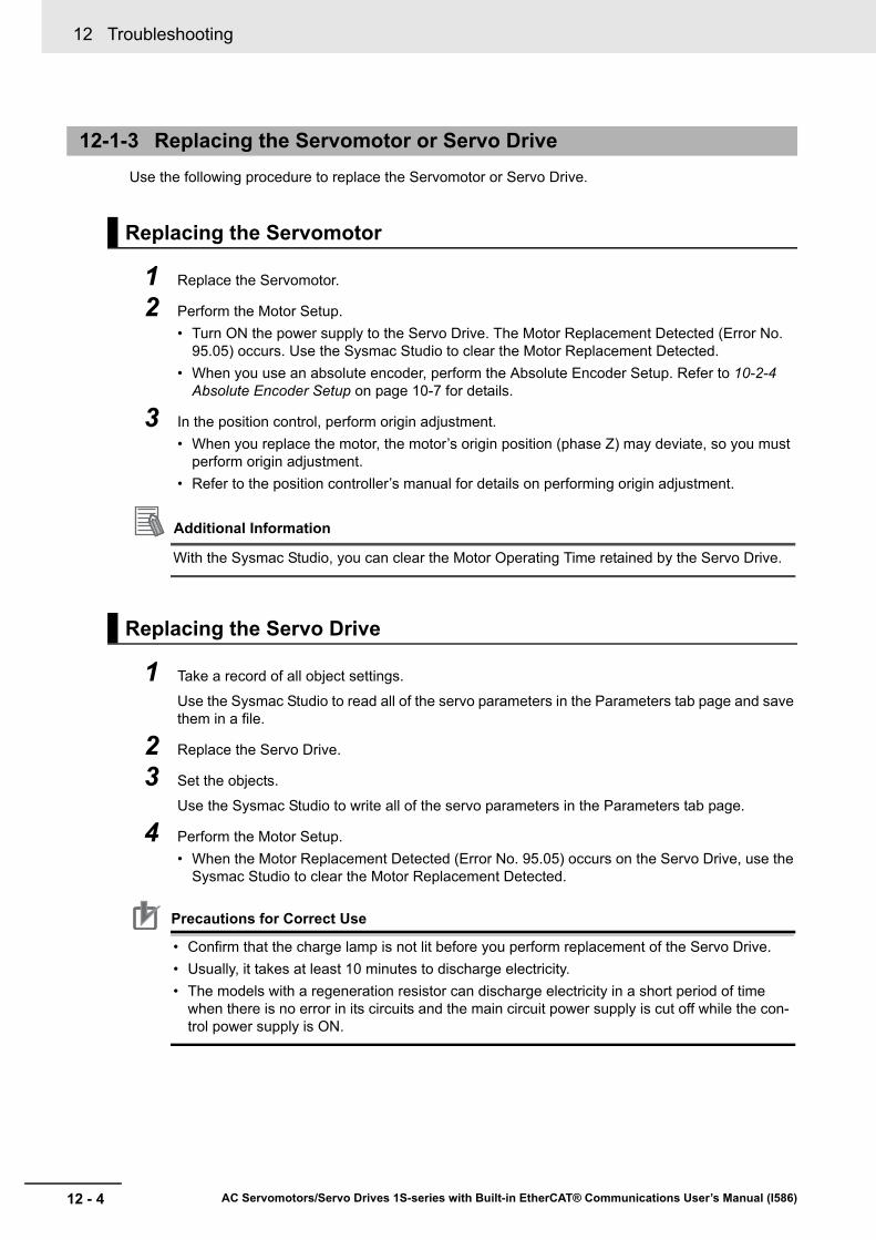
Check the voltage at the power supply input terminals.
Make sure that the power supply voltage for control input signals is within the range of 12 VDC-5% to 24 VDC+5%, and the power supply voltage for safety input signals is within the range of 24 VDC±5%.If the voltage is out of this range, operation failure may result. Be sure that the power supply is within the specified range.
Check whether an error exists by the use of the 7-segment LED display on the front of the Servo Drive or from the Sysmac Studio.
When an Error ExistsCheck the error display ( ) and make an analysis based on the error that is indicated.
Refer to 12-5-1 Troubleshooting Using Error Displays on page 12-14.
When an Error Does Not ExistMake an analysis according to the error conditions.
Refer to 12-5-3 Troubleshooting Using the Operation State on page 12-38.
12-1-1 Preliminary Checks When a Problem Occurs
Checking the Power Supply Voltage
Input terminal Model VoltageMain circuit power supply input (L1, L2, L3)
R88D-1SN L-ECT Single-phase 100 to 120 VAC (85 to 132 V)*1 50/60 Hz
*1. The values outside parentheses indicate the rated value, and the values inside parentheses indicate the range of acceptable variation. If the voltage is out of this range, operation failure may result. Be sure that the power supply is within the specified range.
R88D-1SN H-ECT Single-phase/3-phase 200 to 240 VAC (170 to 252 V)*1 50/60 Hz
R88D-1SN F-ECT 3-phase 380 to 480 VAC (323 to 504 V)*1 50/60 HzControl Circuit Power Supply Input Termi-nals (24 V, or +24 V, 0V)
--- 24 VDC (21.6 to 26.4V)
Checking the Error Occurrence

12 - 3
12 Troubleshooting
AC Servomotors/Servo Drives 1S-series with Built-in EtherCAT® Communications User’s Manual (I586)
12-1 Actions for Problem
s
12
12-1-2 Precautions When a P
roblem O
ccurs
The following figure shows the 7-segment display when an error exists.
Numbers from 0 to F hex are displayed as follows.
When you check and verify I/O after a problem occurred, the Servo Drive may suddenly start to operate or suddenly stop, so always take the following precautions.
You should assume that anything not described in this manual is not possible with this product.
• Disconnect the wiring before checking for cable breakage. If you test conduction with the cable con-nected, test results may not be accurate due to conduction via bypassing circuit.
• If the encoder signal is lost, the Servomotor may run away, or an error may occur. Be sure to discon-nect the Servomotor from mechanical systems before you check the encoder signal.
• When you perform tests, first check that there are no persons in the vicinity of the equipment, andthat the equipment will not be damaged even if the Servomotor runs away.Before you perform the tests, verify that you can immediately stop the machine by the use of func-tions such as the immediate stop in case the machine runs out of control.
12-1-2 Precautions When a Problem Occurs
Precautions
[ER](1 s)
[ST](1 s)
● Error display and warning displayThe preset character, main code and sub code are displayed in turns. Example) Encoder Communications Error: 2101 hex
Error No. main (1 s)
Error No. sub (1 s)
● Information displayST is displayed. Example) STO Detected: C000 hex
EBA C D F521 3 4 6 87 90
12 Troubleshooting
12 - 4 AC Servomotors/Servo Drives 1S-series with Built-in EtherCAT® Communications User’s Manual (I586)
Use the following procedure to replace the Servomotor or Servo Drive.
1 Replace the Servomotor.
2 Perform the Motor Setup.• Turn ON the power supply to the Servo Drive. The Motor Replacement Detected (Error No.
95.05) occurs. Use the Sysmac Studio to clear the Motor Replacement Detected.• When you use an absolute encoder, perform the Absolute Encoder Setup. Refer to 10-2-4
Absolute Encoder Setup on page 10-7 for details.
3 In the position control, perform origin adjustment.• When you replace the motor, the motor’s origin position (phase Z) may deviate, so you must
perform origin adjustment.• Refer to the position controller’s manual for details on performing origin adjustment.
Additional Information
With the Sysmac Studio, you can clear the Motor Operating Time retained by the Servo Drive.
1 Take a record of all object settings.
Use the Sysmac Studio to read all of the servo parameters in the Parameters tab page and save them in a file.
2 Replace the Servo Drive.
3 Set the objects.
Use the Sysmac Studio to write all of the servo parameters in the Parameters tab page.
4 Perform the Motor Setup.• When the Motor Replacement Detected (Error No. 95.05) occurs on the Servo Drive, use the
Sysmac Studio to clear the Motor Replacement Detected.
Precautions for Correct Use
• Confirm that the charge lamp is not lit before you perform replacement of the Servo Drive.• Usually, it takes at least 10 minutes to discharge electricity.• The models with a regeneration resistor can discharge electricity in a short period of time
when there is no error in its circuits and the main circuit power supply is cut off while the con-trol power supply is ON.
12-1-3 Replacing the Servomotor or Servo Drive
Replacing the Servomotor
Replacing the Servo Drive
12 - 5
12 Troubleshooting
AC Servomotors/Servo Drives 1S-series with Built-in EtherCAT® Communications User’s Manual (I586)
12-1 Actions for Problem
s
12
12-1-3 Replacing the S
ervomotor or S
ervo Drive
1 Start the Sysmac Studio and go online with the Servo Drive via EtherCAT or USB communica-tions.
2 In the Sysmac Studio, right-click the target Servo Drive under Configurations and Setup, and select Motor and Encoder.
3 Click the Reset Motor Replacement Detection error button in the Encoder Properties pane.
4 Execute the Unit Restart or turn the control power supply to the Servo Drive OFF and then ON again.
Clearing Motor Replacement Detected
12 Troubleshooting
12 - 6 AC Servomotors/Servo Drives 1S-series with Built-in EtherCAT® Communications User’s Manual (I586)
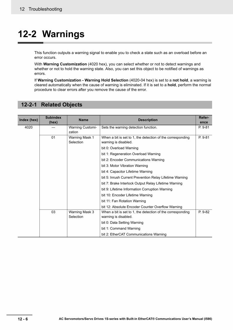
12-2 Warnings
This function outputs a warning signal to enable you to check a state such as an overload before an error occurs.
With Warning Customization (4020 hex), you can select whether or not to detect warnings and whether or not to hold the warning state. Also, you can set this object to be notified of warnings as errors.
If Warning Customization - Warning Hold Selection (4020-04 hex) is set to a not hold, a warning is cleared automatically when the cause of warning is eliminated. If it is set to a hold, perform the normal procedure to clear errors after you remove the cause of the error.
12-2-1 Related Objects
Index (hex) Subindex (hex) Name Description Refer-
ence4020 --- Warning Customi-
zationSets the warning detection function. P. 9-81
01 Warning Mask 1 Selection
When a bit is set to 1, the detection of the corresponding warning is disabled.
bit 0: Overload Warning
bit 1: Regeneration Overload Warning
bit 2: Encoder Communications Warning
bit 3: Motor Vibration Warning
bit 4: Capacitor Lifetime Warning
bit 5: Inrush Current Prevention Relay Lifetime Warning
bit 7: Brake Interlock Output Relay Lifetime Warning
bit 9: Lifetime Information Corruption Warning
bit 10: Encoder Lifetime Warning
bit 11: Fan Rotation Warning
bit 12: Absolute Encoder Counter Overflow Warning
P. 9-81
03 Warning Mask 3 Selection
When a bit is set to 1, the detection of the corresponding warning is disabled.
bit 0: Data Setting Warning
bit 1: Command Warning
bit 2: EtherCAT Communications Warning
P. 9-82

12 - 7
12 Troubleshooting
AC Servomotors/Servo Drives 1S-series with Built-in EtherCAT® Communications User’s Manual (I586)
12-2 Warnings
12
12-2-1 Related O
bjects
4020 04 Warning Hold Selection
Selects whether to hold or not the warning state.
Bit 0:
0: Not hold the warning enabled in Warning Mask 1 Selec-tion.
The warning is automatically cleared when the cause of the warning is eliminated. However, the warning is held for at least 1 second.
1: Hold the warning enabled in Warning Mask 1 Selection.
After the cause of the warning is eliminated, the error reset command must be sent.
Bit 2:
0: Not hold the warning enabled in Warning Mask 3 Selec-tion.
The warning is automatically cleared when the cause of the warning is eliminated. However, the warning is held for at least 1 second.
1: Hold the warning enabled in Warning Mask 3 Selection.
After the cause of the warning is eliminated, the error reset command must be sent.
P. 9-82
05 Warning Level Change 1 Selec-tion
When a bit is set to 1, the level of the corresponding warn-ing is set as the error.
bit 0: Overload Warning
bit 1: Regeneration Overload Warning
bit 2: Encoder Communications Warning
bit 3: Motor Vibration Warning
bit 4: Capacitor Lifetime Warning
bit 5: Inrush Current Prevention Relay Lifetime Warning
bit 7: Brake Interlock Output Relay Lifetime Warning
bit 9: Lifetime Information Corruption Warning
bit 10: Encoder Lifetime Warning
bit 11: Fan Rotation Warning
bit 12: Absolute Encoder Counter Overflow Warning
P. 9-82
07 Warning Level Change 3 Selec-tion
When a bit is set to 1, the level of the corresponding warn-ing is set as the error.
bit 0: Data Setting Warning
bit 1: Command Warning
bit 2: EtherCAT Communications Warning
P. 9-83
Index (hex) Subindex (hex) Name Description Refer-
ence

12 Troubleshooting
12 - 8 AC Servomotors/Servo Drives 1S-series with Built-in EtherCAT® Communications User’s Manual (I586)
Precautions for Correct Use
You can clear these warnings by executing the error rest command. The command does clear the warning even if the cause of the warning is not removed, but the same warning will occur again.
12-2-2 Warning List
General Warnings
Error No.
Warning name Warning condition
Warning Mask 1 Selection*1 (4020-01 hex) Warning Level Change 1 Selection (4020-05 hex)
corresponding bit
*1. For Warning Mask 1 Selection, when a bit is set to 1, the detection of the corresponding warning is disabled.
Main (hex)
Sub (hex)
A0 00 Overload Warning The load ratio of Servo Drive or motor (4150-81 hex) exceeded the level set in Overload - Warning Notification Level (4150-01 hex).
Bit 0
A1 00 Regeneration Overload Warning
The Regeneration Load Ratio (4310-81 hex) exceeded 85% of the regeneration overload ratio.
Bit 1
A3 00 Fan Rotation Warning The rotation speed of the fan is 80% or less of the rating and the cooling performance decreases.
Bit 11
A4 00 Encoder Communications Warning
Encoder communications errors occurred in series more frequently than the specified value.
Bit 2
A6 00 Motor Vibration Warning The motor vibration, which was higher than or equal to the level set in the Vibration Detection - Detection Level (3B70-01 hex), was detected.
Bit 3
A7 01 Capacitor Lifetime Warning
The capacitor built into the Servo Drive reached the service life of the manufacturer’s guarantee.
Bit 4
02 Inrush Current Prevention Relay Lifetime Warning
The inrush current prevention relay built into the Servo Drive reached the service life of the manufacturer's guarantee.
Bit 5
04 Brake Interlock Output Relay Lifetime Warning
The brake interlock output (BKIR) relay built into the Servo Drive reached the service life of the manu-facturer's guarantee.
Bit 7
05 Lifetime Information Corruption Warning
An error was detected in the saved lifetime information.
Bit 9
06 Encoder Lifetime Warning The encoder lifetime is close to the end.
Bit 10
AB 00 Absolute Encoder Counter Overflow Warning
The multi-rotation counter of the encoder exceeded the value set in Encoder - Absolute Encoder Counter Overflow Warning Level (4510-02 hex).
Bit 12
12 - 9
12 Troubleshooting
AC Servomotors/Servo Drives 1S-series with Built-in EtherCAT® Communications User’s Manual (I586)
12-2 Warnings
12
12-2-2 Warning List
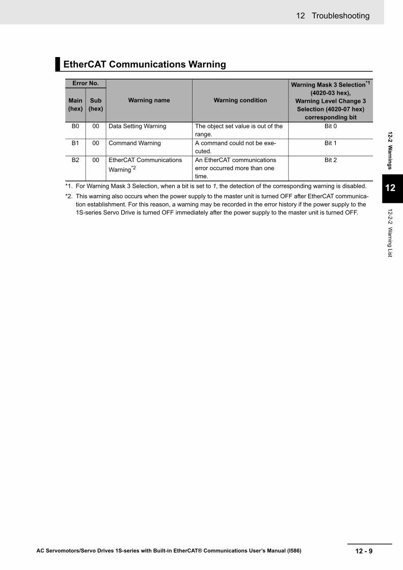
*1. For Warning Mask 3 Selection, when a bit is set to 1, the detection of the corresponding warning is disabled.
*2. This warning also occurs when the power supply to the master unit is turned OFF after EtherCAT communica-tion establishment. For this reason, a warning may be recorded in the error history if the power supply to the 1S-series Servo Drive is turned OFF immediately after the power supply to the master unit is turned OFF.
EtherCAT Communications Warning
Error No.
Warning name Warning condition
Warning Mask 3 Selection*1
(4020-03 hex), Warning Level Change 3 Selection (4020-07 hex)
corresponding bit
Main (hex)
Sub (hex)
B0 00 Data Setting Warning The object set value is out of the range.
Bit 0
B1 00 Command Warning A command could not be exe-cuted.
Bit 1
B2 00 EtherCAT Communications Warning*2
An EtherCAT communications error occurred more than one time.
Bit 2
12 Troubleshooting
12 - 10 AC Servomotors/Servo Drives 1S-series with Built-in EtherCAT® Communications User’s Manual (I586)
12-3 Errors
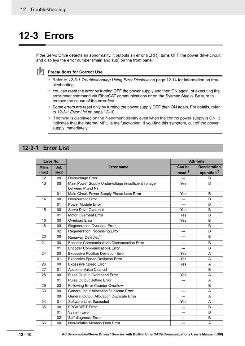
If the Servo Drive detects an abnormality, it outputs an error (/ERR), turns OFF the power drive circuit, and displays the error number (main and sub) on the front panel.
Precautions for Correct Use
• Refer to 12-5-1 Troubleshooting Using Error Displays on page 12-14 for information on trou-bleshooting.
• You can reset the error by turning OFF the power supply and then ON again, or executing the error reset command via EtherCAT communications or on the Sysmac Studio. Be sure to remove the cause of the error first.
• Some errors are reset only by turning the power supply OFF then ON again. For details, refer to 12-3-1 Error List on page 12-10.
• If nothing is displayed on the 7-segment display even when the control power supply is ON, it indicates that the internal MPU is malfunctioning. If you find this symptom, cut off the power supply immediately.
12-3-1 Error List
Error No.Error name
AttributeMain (hex)
Sub (hex)
Can be reset*1
Deceleration operation*2
12 00 Overvoltage Error --- B13 00 Main Power Supply Undervoltage (insufficient voltage
between P and N)Yes B
01 Main Circuit Power Supply Phase Loss Error Yes B14 00 Overcurrent Error --- B
01 Power Module Error --- B15 00 Servo Drive Overheat Yes B
01 Motor Overheat Error Yes B16 00 Overload Error Yes B18 00 Regeneration Overload Error --- B
02 Regeneration Processing Error --- B20 00 Runaway Detected*3 --- B
21 00 Encoder Communications Disconnection Error --- B01 Encoder Communications Error --- B
24 00 Excessive Position Deviation Error Yes A01 Excessive Speed Deviation Error Yes A
26 00 Excessive Speed Error Yes A27 01 Absolute Value Cleared --- B28 00 Pulse Output Overspeed Error Yes A
01 Pulse Output Setting Error --- A29 03 Following Error Counter Overflow --- B33 00 General Input Allocation Duplicate Error --- A
09 General Output Allocation Duplicate Error --- A34 01 Software Limit Exceeded Yes A35 00 FPGA WDT Error --- B
01 System Error --- B02 Self-diagnosis Error --- B
36 00 Non-volatile Memory Data Error --- A
12 - 11
12 Troubleshooting
AC Servomotors/Servo Drives 1S-series with Built-in EtherCAT® Communications User’s Manual (I586)
12-3 Errors
12
12-3-1 Error List
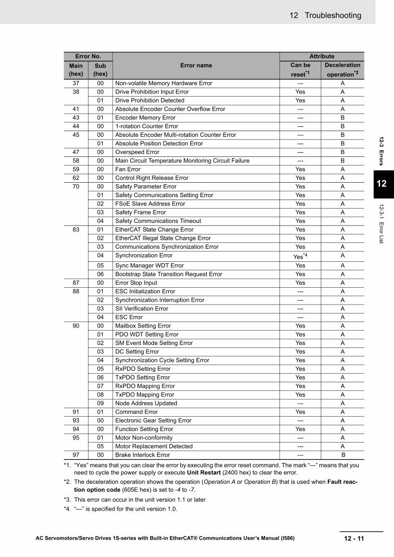
37 00 Non-volatile Memory Hardware Error --- A38 00 Drive Prohibition Input Error Yes A
01 Drive Prohibition Detected Yes A41 00 Absolute Encoder Counter Overflow Error --- A43 01 Encoder Memory Error --- B44 00 1-rotation Counter Error --- B45 00 Absolute Encoder Multi-rotation Counter Error --- B
01 Absolute Position Detection Error --- B47 00 Overspeed Error --- B58 00 Main Circuit Temperature Monitoring Circuit Failure --- B59 00 Fan Error Yes A62 00 Control Right Release Error Yes A70 00 Safety Parameter Error Yes A
01 Safety Communications Setting Error Yes A02 FSoE Slave Address Error Yes A03 Safety Frame Error Yes A04 Safety Communications Timeout Yes A
83 01 EtherCAT State Change Error Yes A02 EtherCAT Illegal State Change Error Yes A03 Communications Synchronization Error Yes A04 Synchronization Error Yes*4 A
05 Sync Manager WDT Error Yes A06 Bootstrap State Transition Request Error Yes A
87 00 Error Stop Input Yes A88 01 ESC Initialization Error --- A
02 Synchronization Interruption Error --- A03 SII Verification Error --- A04 ESC Error --- A
90 00 Mailbox Setting Error Yes A01 PDO WDT Setting Error Yes A02 SM Event Mode Setting Error Yes A03 DC Setting Error Yes A04 Synchronization Cycle Setting Error Yes A05 RxPDO Setting Error Yes A06 TxPDO Setting Error Yes A07 RxPDO Mapping Error Yes A08 TxPDO Mapping Error Yes A09 Node Address Updated --- A
91 01 Command Error Yes A93 00 Electronic Gear Setting Error --- A94 00 Function Setting Error Yes A95 01 Motor Non-conformity --- A
05 Motor Replacement Detected --- A97 00 Brake Interlock Error --- B
*1. “Yes” means that you can clear the error by executing the error reset command. The mark “---” means that you need to cycle the power supply or execute Unit Restart (2400 hex) to clear the error.
*2. The deceleration operation shows the operation (Operation A or Operation B) that is used when Fault reac-tion option code (605E hex) is set to -4 to -7.
*3. This error can occur in the unit version 1.1 or later.*4. “---” is specified for the unit version 1.0.
Error No.Error name
AttributeMain (hex)
Sub (hex)
Can be reset*1
Deceleration operation*2

12 Troubleshooting
12 - 12 AC Servomotors/Servo Drives 1S-series with Built-in EtherCAT® Communications User’s Manual (I586)
The deceleration stop function controls the motor and decelerates it to stop if an error that causes the deceleration stop occurs.
12-3-2 Deceleration Stop Operation at Errors
Related Objects
Index (hex)
Subindex (hex) Name Description Refer-
ence605E 00 Fault reaction option
codeSets the state during deceleration and after stopping for when an error occurs.
P. A-46
3B21 --- Deceleration Stop Sets the torque for deceleration stop. P. 9-6601 Torque Sets the torque limit value during deceleration
stop.P. 9-66
Deceleration Stop Operation
Control
Speed [r/mn]
Time
Velocity commandMotor speed
Control through host commandsControl through host commands
Error that causes the deceleration stop occurs No error Error
Speed determinedas stop
[30 r/min]
Torque control is performed to stop the motor with Deceleration Stop - Torque (3B21-01 hex(measure to reduce shock at the time of stop)
12 - 13
12 Troubleshooting
AC Servomotors/Servo Drives 1S-series with Built-in EtherCAT® Communications User’s Manual (I586)
12-4 Information
12
12-4-1 Related O
bjects
12-4 Information
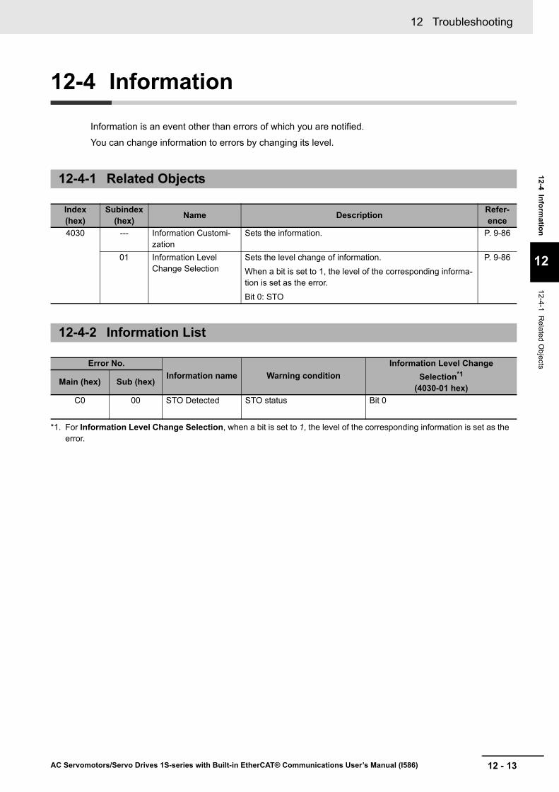
Information is an event other than errors of which you are notified.
You can change information to errors by changing its level.
12-4-1 Related Objects
Index (hex)
Subindex (hex) Name Description Refer-
ence4030 --- Information Customi-
zationSets the information. P. 9-86
01 Information Level Change Selection
Sets the level change of information.
When a bit is set to 1, the level of the corresponding informa-tion is set as the error.
Bit 0: STO
P. 9-86
12-4-2 Information List
Error No.Information name Warning condition
Information Level ChangeSelection*1
(4030-01 hex)
*1. For Information Level Change Selection, when a bit is set to 1, the level of the corresponding information is set as the error.
Main (hex) Sub (hex)
C0 00 STO Detected STO status Bit 0

12 Troubleshooting
12 - 14 AC Servomotors/Servo Drives 1S-series with Built-in EtherCAT® Communications User’s Manual (I586)
12-5 Troubleshooting
If an error occurs in the Servo Drive or operation, identify the cause of the error and take appropriate measures as shown below.• For the error occurrence, check its frequency, timing, and the environment in which the error
occurred.• You can reduce errors that occur temporarily by taking noise countermeasures such as wiring a thick
ground wire as short as possible.• For details on noise countermeasures, refer to 4-3 Wiring Conforming to EMC Directives on page
4-28.
When an error or warning occurs, the error number is displayed on the 7-segment LED display the front of the Servo Drive.
12-5-1 Troubleshooting Using Error Displays
Error List
Error No.Name Cause MeasuresMain
(hex)Sub (hex)
12 00 Overvoltage Error
The main circuit power supply voltage (P-N voltage) exceeded the operation guarantee range.
The P-N voltage exceeded the specified value.
Input the correct voltage.
The input voltage increased.
Use appropriately external devices such as UPS.
The Regeneration Resistor wiring is bro-ken.
If a resistance value of the external resistor is infinite between the ter-minal B1 and B2 of the Servo Drive, the wiring is broken. Replace the external resistor.
The External Regenera-tion Resistor is set or selected inappropriately.
Confirm the necessary regeneration processing capacity, and connect an appropriate External Regenera-tion Resistor. Also, set the parame-ters of the External Regeneration Resistor to the resistance value of the External Regeneration Resistor in use.
Servo Drive failure If this event occurs again after you performed all corrections shown above, replace the Servo Drive.

12 - 15
12 Troubleshooting
AC Servomotors/Servo Drives 1S-series with Built-in EtherCAT® Communications User’s Manual (I586)
12-5 Troubleshooting
12
12-5-1 Troubleshooting Using E
rror Displays
13 00 Main Power Supply Undervolt-age (insuffi-cient voltage between P and N)
The main circuit power supply voltage fell below the operation guaran-tee range during Servo ON.
Incorrect wiring of the main circuit power sup-ply
If the power supply cables are not wired to the main circuit power sup-ply terminals (L1 , L2 , L3), connect them.
The low power supply voltage is applied to the Servo Drive.
Increase the power supply capacity if it is small. Measure the applied power supply voltage, and apply the voltage according to the specifica-tion.
The long time was set in Momentary Hold Time and the voltage was decreased momentarily.
Remove the cause that momentar-ily decreased the voltage. Set a short time in the Momentary Hold Time so as not to detect this error due to a momentary decrease in voltage.
Servo Drive failure If this event occurs again after you performed all corrections shown above, replace the Servo Drive.
01 Main Circuit Power Sup-ply Phase Loss Error
The phase loss of the main circuit power sup-ply was detected.
Incorrect wiring, for example the single-phase power supply is input to a 3-phase input type Servo Drive.
Confirm the Servo Drive specifica-tions, and perform the correct wir-ing.
In the case where the single-phase power supply is input to a sin-gle- and 3-phase input type Servo Drive, the phase loss detection is enabled.
Set Main Circuit Power Supply - Phase Loss Detection Enable (4320-02 hex) to 0 (disabled).
The power supply volt-age is low or insufficient.
Improve power supply conditions by increasing the power supply capac-ity or the like.
Broken wiring of the main circuit power sup-ply input
Replace the main circuit power sup-ply input cable.
Servo Drive failure If this event occurs again after you performed all corrections shown above, replace the Servo Drive.
Error No.Name Cause MeasuresMain
(hex)Sub (hex)
12 Troubleshooting
12 - 16 AC Servomotors/Servo Drives 1S-series with Built-in EtherCAT® Communications User’s Manual (I586)
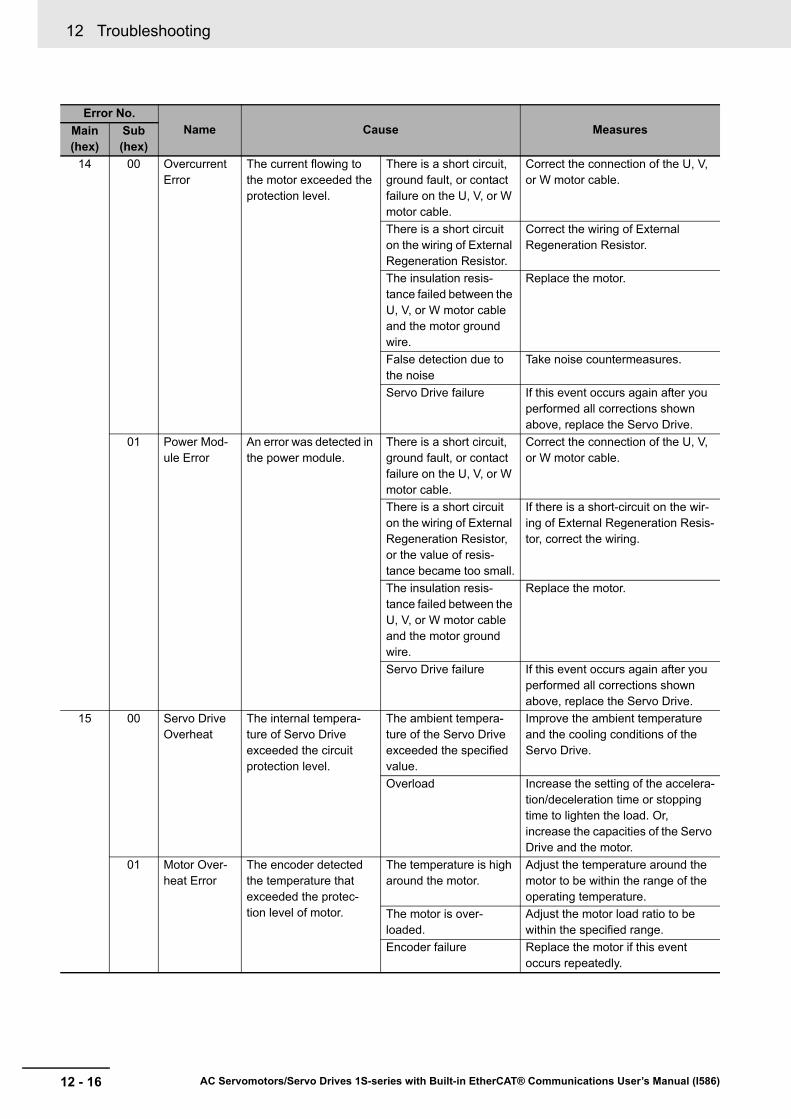
14 00 Overcurrent Error
The current flowing to the motor exceeded the protection level.
There is a short circuit, ground fault, or contact failure on the U, V, or W motor cable.
Correct the connection of the U, V, or W motor cable.
There is a short circuit on the wiring of External Regeneration Resistor.
Correct the wiring of External Regeneration Resistor.
The insulation resis-tance failed between the U, V, or W motor cable and the motor ground wire.
Replace the motor.
False detection due to the noise
Take noise countermeasures.
Servo Drive failure If this event occurs again after you performed all corrections shown above, replace the Servo Drive.
01 Power Mod-ule Error
An error was detected in the power module.
There is a short circuit, ground fault, or contact failure on the U, V, or W motor cable.
Correct the connection of the U, V, or W motor cable.
There is a short circuit on the wiring of External Regeneration Resistor, or the value of resis-tance became too small.
If there is a short-circuit on the wir-ing of External Regeneration Resis-tor, correct the wiring.
The insulation resis-tance failed between the U, V, or W motor cable and the motor ground wire.
Replace the motor.
Servo Drive failure If this event occurs again after you performed all corrections shown above, replace the Servo Drive.
15 00 Servo Drive Overheat
The internal tempera-ture of Servo Drive exceeded the circuit protection level.
The ambient tempera-ture of the Servo Drive exceeded the specified value.
Improve the ambient temperature and the cooling conditions of the Servo Drive.
Overload Increase the setting of the accelera-tion/deceleration time or stopping time to lighten the load. Or, increase the capacities of the Servo Drive and the motor.
01 Motor Over-heat Error
The encoder detected the temperature that exceeded the protec-tion level of motor.
The temperature is high around the motor.
Adjust the temperature around the motor to be within the range of the operating temperature.
The motor is over-loaded.
Adjust the motor load ratio to be within the specified range.
Encoder failure Replace the motor if this event occurs repeatedly.
Error No.Name Cause MeasuresMain
(hex)Sub (hex)

12 - 17
12 Troubleshooting
AC Servomotors/Servo Drives 1S-series with Built-in EtherCAT® Communications User’s Manual (I586)
12-5 Troubleshooting
12
12-5-1 Troubleshooting Using E
rror Displays
16 00 Overload Error
The load ratio of Servo Drive or motor (4105-81 hex) exceeded 100%.
Operation was contin-ued for a long time with high load.
Take the following actions accord-ing to conditions.
• Increase the set value of the acceleration/deceleration time or the stop time.
• Lighten the load.• Adjust the gain or inertia ratio.• If torque waveforms oscillate
excessively, adjust the system by the tuning so that the oscillation does not occur.
• Set the appropriate brake timing.• Increase the capacities of the
Servo Drive and the motor.There is incorrect wir-ing of the motor cable or a broken cable.
• Connect the motor cable as shown in the wiring diagram. If the cable is broken, replace it. Or, connect the motor cable and encoder cable that are used together to the same motor.
• Measure the voltage at the brake terminal. If the brake is applied, release it.
Increase in friction Check machine conditions and remove the cause of the friction.
Error No.Name Cause MeasuresMain
(hex)Sub (hex)
12 Troubleshooting
12 - 18 AC Servomotors/Servo Drives 1S-series with Built-in EtherCAT® Communications User’s Manual (I586)
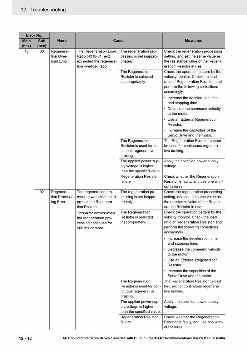
18 00 Regenera-tion Over-load Error
The Regeneration Load Ratio (4310-81 hex) exceeded the regenera-tion overload ratio.
The regeneration pro-cessing is set inappro-priately.
Check the regeneration processing setting, and set the same value as the resistance value of the Regen-eration Resistor in use.
The Regeneration Resistor is selected inappropriately.
Check the operation pattern by the velocity monitor. Check the load ratio of Regeneration Resistor, and perform the following corrections accordingly.
• Increase the deceleration time and stopping time.
• Decrease the command velocity to the motor.
• Use an External Regeneration Resistor.
• Increase the capacities of the Servo Drive and the motor.
The Regeneration Resistor is used for con-tinuous regenerative braking.
The Regeneration Resistor cannot be used for continuous regenera-tive braking.
The applied power sup-ply voltage is higher than the specified value.
Apply the specified power supply voltage.
Regeneration Resistor failure
Check whether the Regeneration Resistor is faulty, and use one with-out failures.
02 Regenera-tion Process-ing Error
The regeneration pro-cessing was stopped to protect the Regenera-tion Resistor.
This error occurs when the regeneration pro-cessing continues for 500 ms or more.
The regeneration pro-cessing is set inappro-priately.
Check the regeneration processing setting, and set the same value as the resistance value of the Regen-eration Resistor in use.
The Regeneration Resistor is selected inappropriately.
Check the operation pattern by the velocity monitor. Check the load ratio of Regeneration Resistor, and perform the following corrections accordingly.
• Increase the deceleration time and stopping time.
• Decrease the command velocity to the motor.
• Use an External Regeneration Resistor.
• Increase the capacities of the Servo Drive and the motor.
The Regeneration Resistor is used for con-tinuous regenerative braking.
The Regeneration Resistor cannot be used for continuous regenera-tive braking.
The applied power sup-ply voltage is higher than the specified value.
Apply the specified power supply voltage.
Regeneration Resistor failure
Check whether the Regeneration Resistor is faulty, and use one with-out failures.
Error No.Name Cause MeasuresMain
(hex)Sub (hex)
12 - 19
12 Troubleshooting
AC Servomotors/Servo Drives 1S-series with Built-in EtherCAT® Communications User’s Manual (I586)
12-5 Troubleshooting
12
12-5-1 Troubleshooting Using E
rror Displays
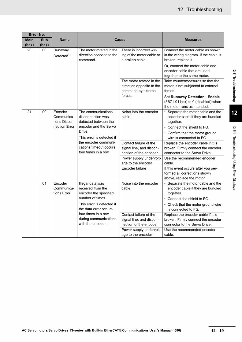
20 00 Runaway Detected*1
The motor rotated in the direction opposite to the command.
There is incorrect wir-ing of the motor cable or a broken cable.
Connect the motor cable as shown in the wiring diagram. If the cable is broken, replace it.
Or, connect the motor cable and encoder cable that are used together to the same motor.
The motor rotated in the direction opposite to the command by external forces.
Take countermeasures so that the motor is not subjected to external forces.
Set Runaway Detection - Enable (3B71-01 hex) to 0 (disabled) when the motor runs as intended.
21 00 Encoder Communica-tions Discon-nection Error
The communications disconnection was detected between the encoder and the Servo Drive.
This error is detected if the encoder communi-cations timeout occurs four times in a row.
Noise into the encoder cable
• Separate the motor cable and the encoder cable if they are bundled together.
• Connect the shield to FG.• Confirm that the motor ground
wire is connected to FG.Contact failure of the signal line, and discon-nection of the encoder
Replace the encoder cable if it is broken. Firmly connect the encoder connector to the Servo Drive.
Power supply undervolt-age to the encoder
Use the recommended encoder cable.
Encoder failure If this event occurs after you per-formed all corrections shown above, replace the motor.
01 Encoder Communica-tions Error
Illegal data was received from the encoder the specified number of times.
This error is detected if the data error occurs four times in a row during communications with the encoder.
Noise into the encoder cable
• Separate the motor cable and the encoder cable if they are bundled together.
• Connect the shield to FG.• Check that the motor ground wire
is connected to FG.Contact failure of the signal line, and discon-nection of the encoder
Replace the encoder cable if it is broken. Firmly connect the encoder connector to the Servo Drive.
Power supply undervolt-age to the encoder
Use the recommended encoder cable.
Error No.Name Cause MeasuresMain
(hex)Sub (hex)
12 Troubleshooting
12 - 20 AC Servomotors/Servo Drives 1S-series with Built-in EtherCAT® Communications User’s Manual (I586)
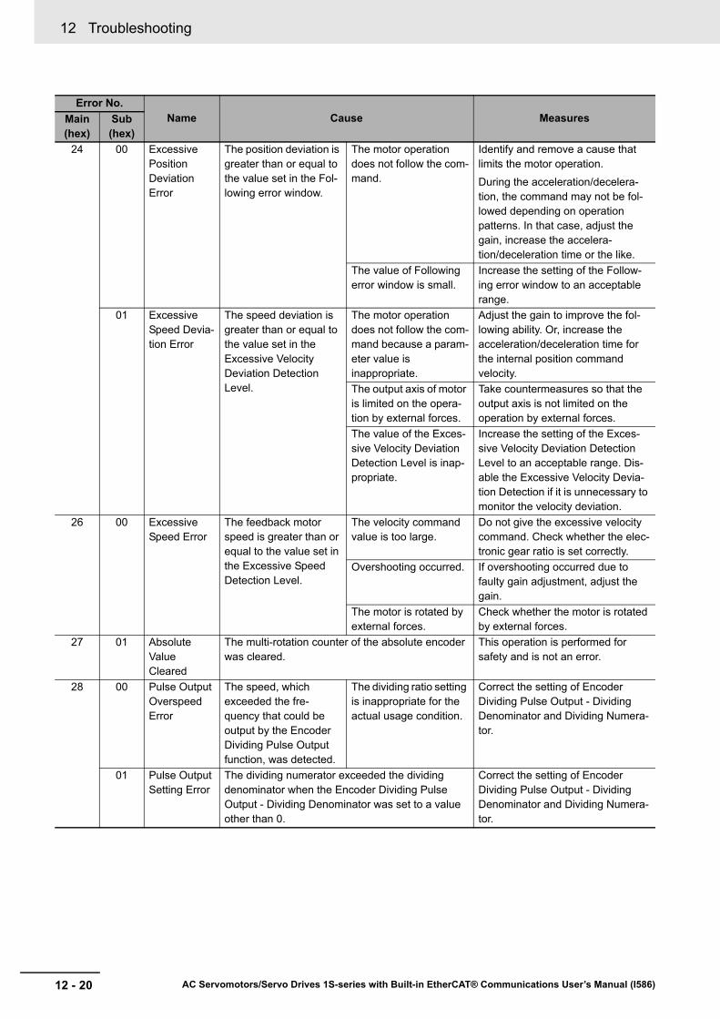
24 00 Excessive Position Deviation Error
The position deviation is greater than or equal to the value set in the Fol-lowing error window.
The motor operation does not follow the com-mand.
Identify and remove a cause that limits the motor operation.
During the acceleration/decelera-tion, the command may not be fol-lowed depending on operation patterns. In that case, adjust the gain, increase the accelera-tion/deceleration time or the like.
The value of Following error window is small.
Increase the setting of the Follow-ing error window to an acceptable range.
01 Excessive Speed Devia-tion Error
The speed deviation is greater than or equal to the value set in the Excessive Velocity Deviation Detection Level.
The motor operation does not follow the com-mand because a param-eter value is inappropriate.
Adjust the gain to improve the fol-lowing ability. Or, increase the acceleration/deceleration time for the internal position command velocity.
The output axis of motor is limited on the opera-tion by external forces.
Take countermeasures so that the output axis is not limited on the operation by external forces.
The value of the Exces-sive Velocity Deviation Detection Level is inap-propriate.
Increase the setting of the Exces-sive Velocity Deviation Detection Level to an acceptable range. Dis-able the Excessive Velocity Devia-tion Detection if it is unnecessary to monitor the velocity deviation.
26 00 Excessive Speed Error
The feedback motor speed is greater than or equal to the value set in the Excessive Speed Detection Level.
The velocity command value is too large.
Do not give the excessive velocity command. Check whether the elec-tronic gear ratio is set correctly.
Overshooting occurred. If overshooting occurred due to faulty gain adjustment, adjust the gain.
The motor is rotated by external forces.
Check whether the motor is rotated by external forces.
27 01 Absolute Value Cleared
The multi-rotation counter of the absolute encoder was cleared.
This operation is performed for safety and is not an error.
28 00 Pulse Output Overspeed Error
The speed, which exceeded the fre-quency that could be output by the Encoder Dividing Pulse Output function, was detected.
The dividing ratio setting is inappropriate for the actual usage condition.
Correct the setting of Encoder Dividing Pulse Output - Dividing Denominator and Dividing Numera-tor.
01 Pulse Output Setting Error
The dividing numerator exceeded the dividing denominator when the Encoder Dividing Pulse Output - Dividing Denominator was set to a value other than 0.
Correct the setting of Encoder Dividing Pulse Output - Dividing Denominator and Dividing Numera-tor.
Error No.Name Cause MeasuresMain
(hex)Sub (hex)
12 - 21
12 Troubleshooting
AC Servomotors/Servo Drives 1S-series with Built-in EtherCAT® Communications User’s Manual (I586)
12-5 Troubleshooting
12
12-5-1 Troubleshooting Using E
rror Displays
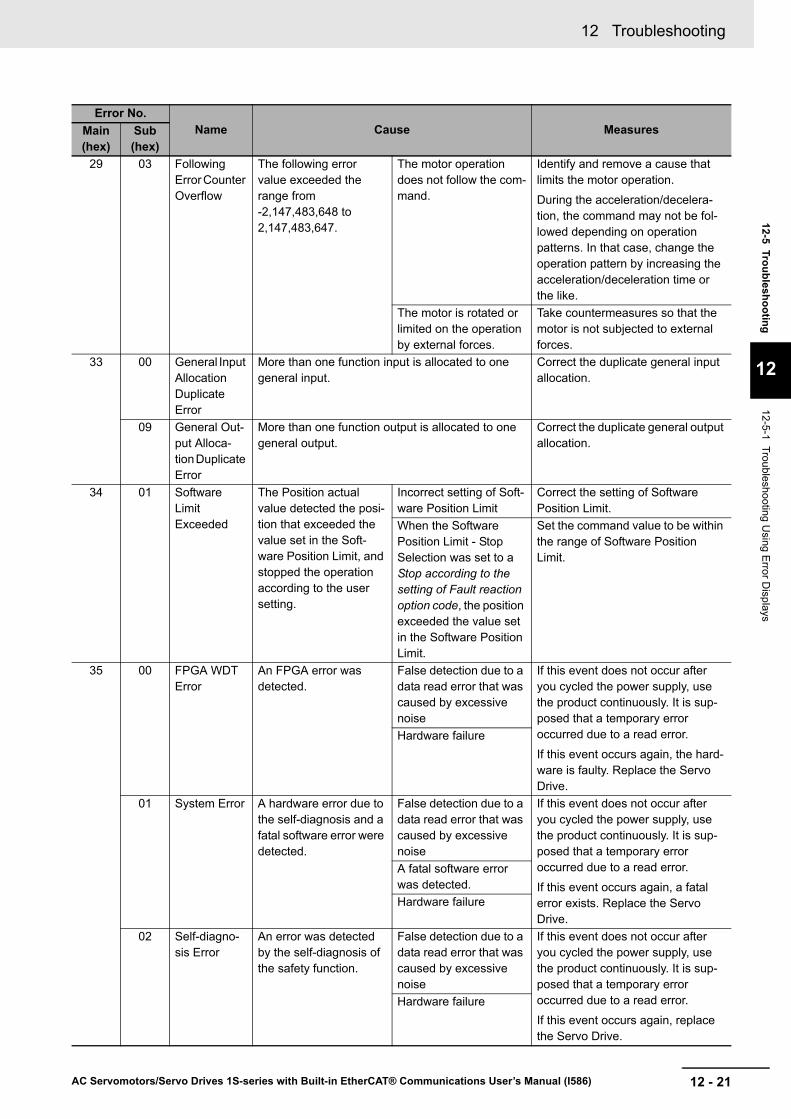
29 03 Following Error Counter Overflow
The following error value exceeded the range from -2,147,483,648 to 2,147,483,647.
The motor operation does not follow the com-mand.
Identify and remove a cause that limits the motor operation.
During the acceleration/decelera-tion, the command may not be fol-lowed depending on operation patterns. In that case, change the operation pattern by increasing the acceleration/deceleration time or the like.
The motor is rotated or limited on the operation by external forces.
Take countermeasures so that the motor is not subjected to external forces.
33 00 General Input Allocation Duplicate Error
More than one function input is allocated to one general input.
Correct the duplicate general input allocation.
09 General Out-put Alloca-tion Duplicate Error
More than one function output is allocated to one general output.
Correct the duplicate general output allocation.
34 01 Software Limit Exceeded
The Position actual value detected the posi-tion that exceeded the value set in the Soft-ware Position Limit, and stopped the operation according to the user setting.
Incorrect setting of Soft-ware Position Limit
Correct the setting of Software Position Limit.
When the Software Position Limit - Stop Selection was set to a Stop according to the setting of Fault reaction option code, the position exceeded the value set in the Software Position Limit.
Set the command value to be within the range of Software Position Limit.
35 00 FPGA WDT Error
An FPGA error was detected.
False detection due to a data read error that was caused by excessive noise
If this event does not occur after you cycled the power supply, use the product continuously. It is sup-posed that a temporary error occurred due to a read error.
If this event occurs again, the hard-ware is faulty. Replace the Servo Drive.
Hardware failure
01 System Error A hardware error due to the self-diagnosis and a fatal software error were detected.
False detection due to a data read error that was caused by excessive noise
If this event does not occur after you cycled the power supply, use the product continuously. It is sup-posed that a temporary error occurred due to a read error.
If this event occurs again, a fatal error exists. Replace the Servo Drive.
A fatal software error was detected.Hardware failure
02 Self-diagno-sis Error
An error was detected by the self-diagnosis of the safety function.
False detection due to a data read error that was caused by excessive noise
If this event does not occur after you cycled the power supply, use the product continuously. It is sup-posed that a temporary error occurred due to a read error.
If this event occurs again, replace the Servo Drive.
Hardware failure
Error No.Name Cause MeasuresMain
(hex)Sub (hex)

12 Troubleshooting
12 - 22 AC Servomotors/Servo Drives 1S-series with Built-in EtherCAT® Communications User’s Manual (I586)
36 00 Non-volatile Memory Data Error
An error of data saved in the non-volatile mem-ory was detected.
Power interruption or noise occurred while parameters other than the safety were saved
Save data after setting the parame-ter again, and cycle the power sup-ply.
Power interruption or noise occurred while the motor identity informa-tion was saved
Execute Motor Setup, and cycle the power supply.
Power interruption or noise occurred while safety parameters were saved
Clear the FSoE slave address, exe-cute FSoE Enable Reset, and cycle the power supply.
37 00 Non-volatile Memory Hardware Error
An error occurred on the non-volatile memory.
False detection due to a data read error that was caused by excessive noise
After you cycled the power supply, if this error occurs continuously although the error is reset, the non-volatile memory is faulty. Replace the Servo Drive.Non-volatile memory
failure38 00 Drive Prohibi-
tion Input Error
Both the Positive Drive Prohibition (POT) and the Negative Drive Pro-hibition Input (NOT) turned ON.
An error occurred on the switch, wire, power sup-ply, and wiring that was connected to the Posi-tive Drive Prohibition Input (POT) or Nega-tive Drive Prohibition Input (NOT).
Check and correct an error on the switch, wire, power supply, and wir-ing that is connected to the Positive Drive Prohibition Input or Negative Drive Prohibition Input.
False detection occurred because the control signal power supply was turned ON slowly.
Check whether the control signal power supply (12 to 24 VDC) is turned ON slowly, and adjust the timing if it is slow.
01 Drive Prohibi-tion Detected
The operation was stopped according to the user setting because the motor ran in the prohibited direc-tion when the Drive Pro-hibition was enabled.
Incorrect or broken wir-ing of Positive Drive Prohibition Input (POT) or Negative Drive Prohi-bition Input (NOT)
Correct the wiring if the Positive Drive Prohibition Input (POT) or Negative Drive Prohibition Input (NOT) is wired incorrectly.
If the cable is broken, replace it.Incorrect setting of the Drive Prohibition Input
Review the setting of the drive pro-hibition input port and set it cor-rectly.
41 00 Absolute Encoder Counter Overflow Error
The multi-rotation counter of the encoder exceeded the maxi-mum number of rota-tions.
An inappropriate value was set in the Encoder - Operation Selection when Using Absolute Encoder (4510-01 hex).
Set the appropriate value in the Encoder - Operation Selection when Using Absolute Encoder (4510-01 hex).
The multi-rotation num-ber of the encoder exceeded the maxi-mum number of rota-tions.
Set the travel distance so that the multi-rotation number does not exceed the maximum number of rotations.
Error No.Name Cause MeasuresMain
(hex)Sub (hex)
12 - 23
12 Troubleshooting
AC Servomotors/Servo Drives 1S-series with Built-in EtherCAT® Communications User’s Manual (I586)
12-5 Troubleshooting
12
12-5-1 Troubleshooting Using E
rror Displays
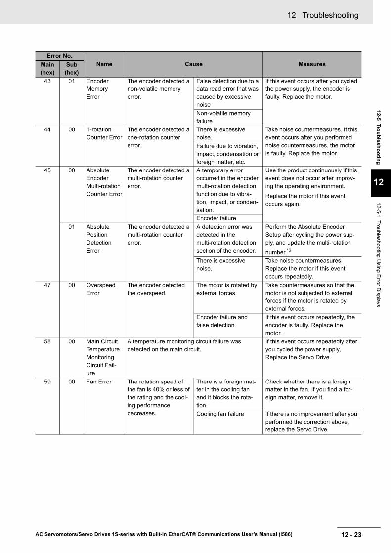
43 01 Encoder Memory Error
The encoder detected a non-volatile memory error.
False detection due to a data read error that was caused by excessive noise
If this event occurs after you cycled the power supply, the encoder is faulty. Replace the motor.
Non-volatile memory failure
44 00 1-rotation Counter Error
The encoder detected a one-rotation counter error.
There is excessive noise.
Take noise countermeasures. If this event occurs after you performed noise countermeasures, the motor is faulty. Replace the motor.
Failure due to vibration, impact, condensation or foreign matter, etc.
45 00 Absolute Encoder Multi-rotation Counter Error
The encoder detected a multi-rotation counter error.
A temporary error occurred in the encoder multi-rotation detection function due to vibra-tion, impact, or conden-sation.
Use the product continuously if this event does not occur after improv-ing the operating environment.
Replace the motor if this event occurs again.
Encoder failure01 Absolute
Position Detection Error
The encoder detected a multi-rotation counter error.
A detection error was detected in the multi-rotation detection section of the encoder.
Perform the Absolute Encoder Setup after cycling the power sup-ply, and update the multi-rotation number.*2
There is excessive noise.
Take noise countermeasures. Replace the motor if this event occurs repeatedly.
47 00 Overspeed Error
The encoder detected the overspeed.
The motor is rotated by external forces.
Take countermeasures so that the motor is not subjected to external forces if the motor is rotated by external forces.
Encoder failure and false detection
If this event occurs repeatedly, the encoder is faulty. Replace the motor.
58 00 Main Circuit Temperature Monitoring Circuit Fail-ure
A temperature monitoring circuit failure was detected on the main circuit.
If this event occurs repeatedly after you cycled the power supply, Replace the Servo Drive.
59 00 Fan Error The rotation speed of the fan is 40% or less of the rating and the cool-ing performance decreases.
There is a foreign mat-ter in the cooling fan and it blocks the rota-tion.
Check whether there is a foreign matter in the fan. If you find a for-eign matter, remove it.
Cooling fan failure If there is no improvement after you performed the correction above, replace the Servo Drive.
Error No.Name Cause MeasuresMain
(hex)Sub (hex)
12 Troubleshooting
12 - 24 AC Servomotors/Servo Drives 1S-series with Built-in EtherCAT® Communications User’s Manual (I586)
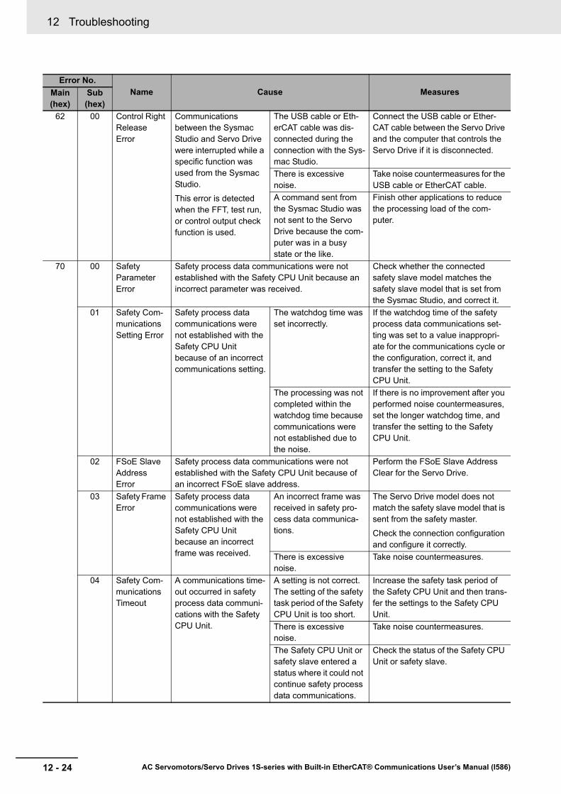
62 00 Control Right Release Error
Communications between the Sysmac Studio and Servo Drive were interrupted while a specific function was used from the Sysmac Studio.
This error is detected when the FFT, test run, or control output check function is used.
The USB cable or Eth-erCAT cable was dis-connected during the connection with the Sys-mac Studio.
Connect the USB cable or Ether-CAT cable between the Servo Drive and the computer that controls the Servo Drive if it is disconnected.
There is excessive noise.
Take noise countermeasures for the USB cable or EtherCAT cable.
A command sent from the Sysmac Studio was not sent to the Servo Drive because the com-puter was in a busy state or the like.
Finish other applications to reduce the processing load of the com-puter.
70 00 Safety Parameter Error
Safety process data communications were not established with the Safety CPU Unit because an incorrect parameter was received.
Check whether the connected safety slave model matches the safety slave model that is set from the Sysmac Studio, and correct it.
01 Safety Com-munications Setting Error
Safety process data communications were not established with the Safety CPU Unit because of an incorrect communications setting.
The watchdog time was set incorrectly.
If the watchdog time of the safety process data communications set-ting was set to a value inappropri-ate for the communications cycle or the configuration, correct it, and transfer the setting to the Safety CPU Unit.
The processing was not completed within the watchdog time because communications were not established due to the noise.
If there is no improvement after you performed noise countermeasures, set the longer watchdog time, and transfer the setting to the Safety CPU Unit.
02 FSoE Slave Address Error
Safety process data communications were not established with the Safety CPU Unit because of an incorrect FSoE slave address.
Perform the FSoE Slave Address Clear for the Servo Drive.
03 Safety Frame Error
Safety process data communications were not established with the Safety CPU Unit because an incorrect frame was received.
An incorrect frame was received in safety pro-cess data communica-tions.
The Servo Drive model does not match the safety slave model that is sent from the safety master.
Check the connection configuration and configure it correctly.
There is excessive noise.
Take noise countermeasures.
04 Safety Com-munications Timeout
A communications time-out occurred in safety process data communi-cations with the Safety CPU Unit.
A setting is not correct. The setting of the safety task period of the Safety CPU Unit is too short.
Increase the safety task period of the Safety CPU Unit and then trans-fer the settings to the Safety CPU Unit.
There is excessive noise.
Take noise countermeasures.
The Safety CPU Unit or safety slave entered a status where it could not continue safety process data communications.
Check the status of the Safety CPU Unit or safety slave.
Error No.Name Cause MeasuresMain
(hex)Sub (hex)

12 - 25
12 Troubleshooting
AC Servomotors/Servo Drives 1S-series with Built-in EtherCAT® Communications User’s Manual (I586)
12-5 Troubleshooting
12
12-5-1 Troubleshooting Using E
rror Displays
83 01 EtherCAT State Change Error
A communications state change command was received for which the current communications state could not be changed.
Check the command specifications for communications state transi-tions in the host controller and cor-rect host controller processing.
02 EtherCAT Illegal State Change Error
An undefined communications state change com-mand was received.
Check the command specifications for communications state transi-tions in the host controller and cor-rect host controller processing.
03 Communica-tions Syn-chronization Error
Communications were not established consec-utively because the syn-chronization with the EtherCAT Master could not be achieved.
The power supply to the host controller was interrupted during PDO communications.
Reset the error in the host control-ler. This event reports an error that was detected when the power sup-ply to the host controller was inter-rupted. It does not indicate that an error currently exists.
An EtherCAT communi-cations cable is discon-nected, loose, broken, or has a contact failure.
Connect the EtherCAT communica-tions cable securely. If the cable is broken, replace it.
Noise Take noise countermeasures if excessive noise affects the Ether-CAT communications cable.
04 Synchroniza-tion Error
A signal for synchro-nous communications could not be detected.
Noise Take noise countermeasures if excessive noise affects the Ether-CAT communications cable.
Error of the EtherCAT slave communications controller
If this event occurs again after you cycled the power supply, replace the Servo Drive.
05 Sync Man-ager WDT Error
PDO communications were interrupted for the allowable period or lon-ger.
An EtherCAT communi-cations cable is discon-nected, loose, or broken.
Connect the EtherCAT communica-tions cable securely.
Host controller error Check the operation of the host controller. Take appropriate countermeasures if there is a prob-lem.
06 Bootstrap State Transi-tion Request Error
The state transition to unsupported Bootstrap was requested.
Check the EtherCAT master setting so that the EtherCAT master does not request the transition to Boot-strap.
87 00 Error Stop Input
The Error Stop Input (ESTP) is active.
The Error Stop Input (ESTP) was input.
Remove the cause of Error Stop Input (ESTP).
The Error Stop Input (ESTP) is incorrectly wired.
Correct the wiring if the Error Stop Input (ESTP) is incorrectly wired.
Error No.Name Cause MeasuresMain
(hex)Sub (hex)

12 Troubleshooting
12 - 26 AC Servomotors/Servo Drives 1S-series with Built-in EtherCAT® Communications User’s Manual (I586)
88 01 ESC Initial-ization Error
The initialization of Eth-erCAT slave communi-cations controller failed.
Data was incorrectly written in the non-vola-tile memory of the Eth-erCAT slave communications con-troller.
If this event does not occur after you cycled the power supply, use the product continuously. It is sup-posed that a temporary error occurred due to a read error.
If this event occurs again, replace the Servo Drive.Failure of the EtherCAT
slave communications controller
02 Synchroniza-tion Interrup-tion Error
Synchronization inter-ruption did not occur within the specified period.
Incorrect EtherCAT syn-chronization setting of the host controller.
Set the synchronization setting of the host controller according to the synchronization specifications for the EtherCAT slave.
Failure of the EtherCAT slave communications controller or false detec-tion
If this event does not occur after you cycled the power supply, use the product continuously. It is sup-posed that a temporary error occurred due to a read error. If this event occurs again, the Servo Drive is faulty. Replace the Servo Drive.
03 SII Verifica-tion Error
An error occurred in SII data of the EtherCAT slave communications controller.
Data was incorrectly overwritten in the non-volatile memory of the EtherCAT slave communications con-troller.
If this event does not occur after you cycled the power supply, use the product continuously. It is sup-posed that a temporary error occurred due to a read error.
If this event occurs again, replace the Servo Drive.Failure of the EtherCAT
slave communications controller or false detec-tion
04 ESC Error An error occurred in the EtherCAT slave communi-cations controller.
If this event occurs repeatedly after you cycled the power supply, the EtherCAT slave communications controller is faulty. Replace the Servo Drive.
Error No.Name Cause MeasuresMain
(hex)Sub (hex)

12 - 27
12 Troubleshooting
AC Servomotors/Servo Drives 1S-series with Built-in EtherCAT® Communications User’s Manual (I586)
12-5 Troubleshooting
12
12-5-1 Troubleshooting Using E
rror Displays
90 00 Mailbox Set-ting Error
An incorrect mailbox setting of Sync Manager was detected.
Check the mailbox setting, and then download it to the EtherCAT master again.
01 PDO WDT Setting Error
An incorrect PDO WDT setting was detected. Check the PDO WDT setting, and then download it to the EtherCAT master again.
02 SM Event Mode Set-ting Error
The unsupported SM Event Mode was set. Check the synchronization setting, and then download it to the Ether-CAT master again.
03 DC Setting Error
A mistake was made in the DC Mode operation setting.
Check the DC Mode setting, and then download it to the EtherCAT master again.
04 Synchroniza-tion Cycle Setting Error
When the DC mode was established, the cycle time was set to the inop-erable value.
In the variable PDO mapping, the maximum number of objects you can map is specified as follows: 6 for both RxPDO and TxPDO for the communication period of 125 µs, 10 for both RxPDO and TxPDO for other com-munication periods. An error occurs if you map a larger number of objects than that speci-fied above.
This error is also detected in the following case: the cycle time is an integral multiple of 125 µs and is not 10 ms or lower.
The variable PDO map-ping is used, and the number of objects is more than the maximum number of mapped objects for the cycle time.
Set the number of objects to a value smaller than the maximum number of mapped objects for the cycle time.
The cycle time setting is incorrect.
Correct the cycle time setting.
05 RxPDO Set-ting Error
An RxPDO setting error was detected.
The RxPDO setting of EtherCAT master is incorrect.
Correct the RxPDO setting accord-ing to the definition of ESI of Servo Drive, and then download it to the EtherCAT master again.
If this event occurs repeatedly after the download to the EtherCAT mas-ter, the Servo Drive is faulty. Replace the Servo Drive.
Servo Drive failure
06 TxPDO Set-ting Error
A TxPDO setting error was detected.
The TxPDO setting of EtherCAT master is incorrect.
Correct the TxPDO setting accord-ing to the definition of ESI of Servo Drive, and then download it to the EtherCAT master again.
If this event occurs repeatedly after the download to the EtherCAT mas-ter, the Servo Drive is faulty. Replace the Servo Drive.
Servo Drive failure
Error No.Name Cause MeasuresMain
(hex)Sub (hex)

12 Troubleshooting
12 - 28 AC Servomotors/Servo Drives 1S-series with Built-in EtherCAT® Communications User’s Manual (I586)
90 07 RxPDO Map-ping Error
An incorrect RxPDO was set, such as out of the allowable range of Index, Subindex, or size.
This error is detected when the following settings are made.
• If an object which cannot be mapped as a PDO is mapped
• If the total size of objects mapped as the safety process data exceeds the specified size
• If the total size of objects mapped to Sync Man-ager 2 PDO Assignment is one byte
• If the total size of objects mapped as the variable PDOs exceeds the maximum size
• If 1710 hex is not mapped while 1B10 hex is mapped (in 1B10 hex/1710 hex mapping)
• If there were too many or too little data in 1710 hex
• If the process data components were included in PDOs other than 1710 hex
Correct the RxPDO setting, and then download it to the EtherCAT master again.
08 TxPDO Map-ping Error
An incorrect TxPDO was set, such as out of the allowable range of Index, Subindex, or size.
This error is detected when the following settings are made.
• If an object which cannot be mapped as a PDO is mapped
• If the total size of objects mapped as the safety process data exceeds the specified size
• If the total size of objects mapped to Sync Man-ager 3 PDO Assignment is one byte
• If the total size of objects mapped as the variable PDOs exceeds the maximum size
• If 1B10 hex is not mapped while 1710 hex is mapped (in 1710 hex/1B10 hex mapping)
• If there were too many or too little data in 1B10 hex
• If the process data components were included in PDOs other than 1B10 hex
Correct the TxPDO setting, and then download it to the EtherCAT master again.
09 Node Address Updated
The node address is changed from a set value in Sysmac Studio to a value of the ID switches.
Check the node address value. Set a correct value if it is wrong.
Error No.Name Cause MeasuresMain
(hex)Sub (hex)
12 - 29
12 Troubleshooting
AC Servomotors/Servo Drives 1S-series with Built-in EtherCAT® Communications User’s Manual (I586)
12-5 Troubleshooting
12
12-5-1 Troubleshooting Using E
rror Displays
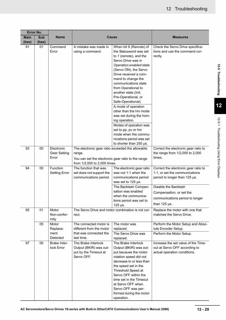
91 01 Command Error
A mistake was made in using a command.
When bit 9 (Remote) of the Statusword was set to 1 (remote), and the Servo Drive was in Operation enabled state (Servo ON), the Servo Drive received a com-mand to change the communications state from Operational to another state (Init, Pre-Operational, or Safe-Operational).
Check the Servo Drive specifica-tions and use the command cor-rectly.
A mode of operation other than the hm mode was set during the hom-ing operation.Modes of operation was set to pp, pv or hm mode when the commu-nications period was set to shorter than 250 μs.
93 00 Electronic Gear Setting Error
The electronic gear ratio exceeded the allowable range.
You can set the electronic gear ratio to the range from 1/2,000 to 2,000 times.
Correct the electronic gear ratio to the range from 1/2,000 to 2,000 times.
94 00 Function Setting Error
The function that was set does not support the communications period.
The electronic gear ratio was not 1:1 when the communications period was set to 125 μs.
Correct the electronic gear ratio to 1:1, or set the communications period to longer than 125 µs.
The Backlash Compen-sation was enabled when the communica-tions period was set to 125 μs.
Disable the Backlash
Compensation, or set the
communications period to longer
than 125 μs.
95 01 Motor Non-confor-mity
The Servo Drive and motor combination is not cor-rect.
Replace the motor with one that matches the Servo Drive.
05 Motor Replace-ment Detected
The connected motor is different from the motor that was connected the last time.
The motor was replaced.
Perform the Motor Setup and Abso-lute Encoder Setup.
The Servo Drive was replaced.
Perform the Motor Setup.
97 00 Brake Inter-lock Error
The Brake Interlock Output (BKIR) was out-put by the Timeout at Servo OFF.
The Brake Interlock Output (BKIR) was out-put because the motor rotation speed did not decrease to or less than the speed set in the Threshold Speed at Servo OFF within the time set in the Timeout at Servo OFF when Servo OFF was per-formed during the motor operation.
Increase the set value of the Time-out at Servo OFF according to actual operation conditions.
Error No.Name Cause MeasuresMain
(hex)Sub (hex)

12 Troubleshooting
12 - 30 AC Servomotors/Servo Drives 1S-series with Built-in EtherCAT® Communications User’s Manual (I586)
A0 00 Overload Warning
The load ratio of Servo Drive or motor (4150-81 hex) exceeded the level set in the Overload - Warning Notification Level.
Operation was contin-ued for a long time with high load.
Perform the following corrections accordingly.
• Increase the set value of the acceleration/deceleration time or the stop time.
• Lighten the load.• Adjust the gain and inertia ratio.• If torque waveforms oscillate
excessively, adjust the system by the tuning so that the oscillation does not occur.
• Set the appropriate brake timing.• Increase the capacities of the
Servo Drive and the motor.There is incorrect wir-ing of the motor cable or a broken cable.
• Connect the motor cable as shown in the wiring diagram. If the cable is broken, replace it. Or, connect the motor cable and encoder cable that are used together to the same motor.
• Measure the voltage at the brake terminal. If the brake is applied, release it.
Increase in friction Check machine conditions and remove the cause of the friction.
A1 00 Regenera-tion Over-load Warning
The Regeneration Load Ratio (4310-81 hex) exceeded 85% of the regeneration overload ratio.
The regeneration pro-cessing is set inappro-priately.
Check the regeneration processing setting, and set the same value as the resistance value of the Regen-eration Resistor in use.
The Regeneration Resistor is selected inappropriately.
Check the operation pattern by the velocity monitor. Check the load ratio of Regeneration Resistor, and perform the following corrections accordingly.
• Increase the deceleration time and stopping time.
• Decrease the command velocity to the motor.
• Use an External Regeneration Resistor.
• Increase the capacities of the Servo Drive and the motor.
This Regeneration Resistor is used for con-tinuous regenerative braking.
The Regeneration Resistor cannot be used for continuous regenera-tive braking.
The applied power sup-ply voltage is higher than the specified value.
Apply the specified power supply voltage.
Regeneration Resistor failure
Check whether the Regeneration Resistor is faulty, and use one with-out failures.
Error No.Name Cause MeasuresMain
(hex)Sub (hex)
12 - 31
12 Troubleshooting
AC Servomotors/Servo Drives 1S-series with Built-in EtherCAT® Communications User’s Manual (I586)
12-5 Troubleshooting
12
12-5-1 Troubleshooting Using E
rror Displays
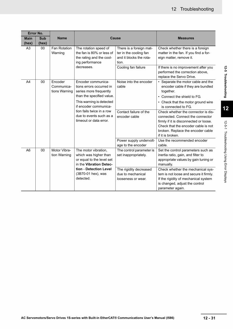
A3 00 Fan Rotation Warning
The rotation speed of the fan is 80% or less of the rating and the cool-ing performance decreases.
There is a foreign mat-ter in the cooling fan and it blocks the rota-tion.
Check whether there is a foreign matter in the fan. If you find a for-eign matter, remove it.
Cooling fan failure If there is no improvement after you performed the correction above, replace the Servo Drive.
A4 00 Encoder Communica-tions Warning
Encoder communica-tions errors occurred in series more frequently than the specified value.
This warning is detected if encoder communica-tion fails twice in a row due to events such as a timeout or data error.
Noise into the encoder cable
• Separate the motor cable and the encoder cable if they are bundled together.
• Connect the shield to FG.• Check that the motor ground wire
is connected to FG.Contact failure of the encoder cable
Check whether the connector is dis-connected. Connect the connector firmly if it is disconnected or loose. Check that the encoder cable is not broken. Replace the encoder cable if it is broken.
Power supply undervolt-age to the encoder
Use the recommended encoder cable.
A6 00 Motor Vibra-tion Warning
The motor vibration, which was higher than or equal to the level set in the Vibration Detec-tion - Detection Level (3B70-01 hex), was detected.
The control parameter is set inappropriately.
Set the control parameters such as inertia ratio, gain, and filter to appropriate values by gain tuning or manually.
The rigidity decreased due to mechanical looseness or wear.
Check whether the mechanical sys-tem is not loose and secure it firmly. If the rigidity of mechanical system is changed, adjust the control parameter again.
Error No.Name Cause MeasuresMain
(hex)Sub (hex)

12 Troubleshooting
12 - 32 AC Servomotors/Servo Drives 1S-series with Built-in EtherCAT® Communications User’s Manual (I586)
A7 01 Capacitor Lifetime Warning
The capacitor built into the Servo Drive reached the service life.
The operating time of the capacitor in the Servo Drive exceeded the service life.
Send the Servo Drive for repair or replace the Servo Drive with a new one. It is necessary to replace the component that reached the service life.02 Inrush Cur-
rent Preven-tion Relay Lifetime Warning
The inrush current pre-vention relay built into the Servo Drive reached the service life.
The number of operat-ing times of the inrush current prevention relay in the Servo Drive exceeded the service life.*3
04 Brake Inter-lock Output Relay Life-time Warning
The brake interlock out-put (BKIR) relay built into the Servo Drive reached the service life.
The number of operat-ing times of the brake interlock output in the Servo Drive exceeded the service life.*3
05 Lifetime Information Corruption Warning
An error was detected in the saved lifetime infor-mation.
The lifetime information corruption was detected when the power supply was turned ON.
Perform the Lifetime Information Clear. Note that the lifetime may not be detected correctly after the clear operation because the value of life-time information is cleared.
If this event occurs repeatedly, the area to save lifetime information is faulty. Replace the Servo Drive.
06 Encoder Life-time Warning
The encoder lifetime is close to the end.
Temporary noise If this event occurs repeatedly, the lifetime is close to the end. Replace the motor.
The end of the encoder life
AB 00 Absolute Encoder Counter Overflow Warning
The multi-rotation counter of the encoder exceeded the value set in Encoder - Absolute Encoder Counter Overflow Warning Level (4510-02 hex).
An inappropriate value was set in the Encoder - Operation Selection when Using Absolute Encoder (4510-01 hex).
Set an appropriate value in the Encoder - Operation Selection when Using Absolute Encoder (4510-01 hex).
The multi-rotation num-ber of the encoder exceeded the warning level.
Set the travel distance so that the multi-rotation number does not exceed the value set in the Encoder - Absolute Encoder Counter Overflow Warning Level (4510-02 hex).
B0 00 Data Setting Warning
The object set value is out of the range. Correct the object setting to be within the specified range.
Error No.Name Cause MeasuresMain
(hex)Sub (hex)
12 - 33
12 Troubleshooting
AC Servomotors/Servo Drives 1S-series with Built-in EtherCAT® Communications User’s Manual (I586)
12-5 Troubleshooting
12
12-5-1 Troubleshooting Using E
rror Displays
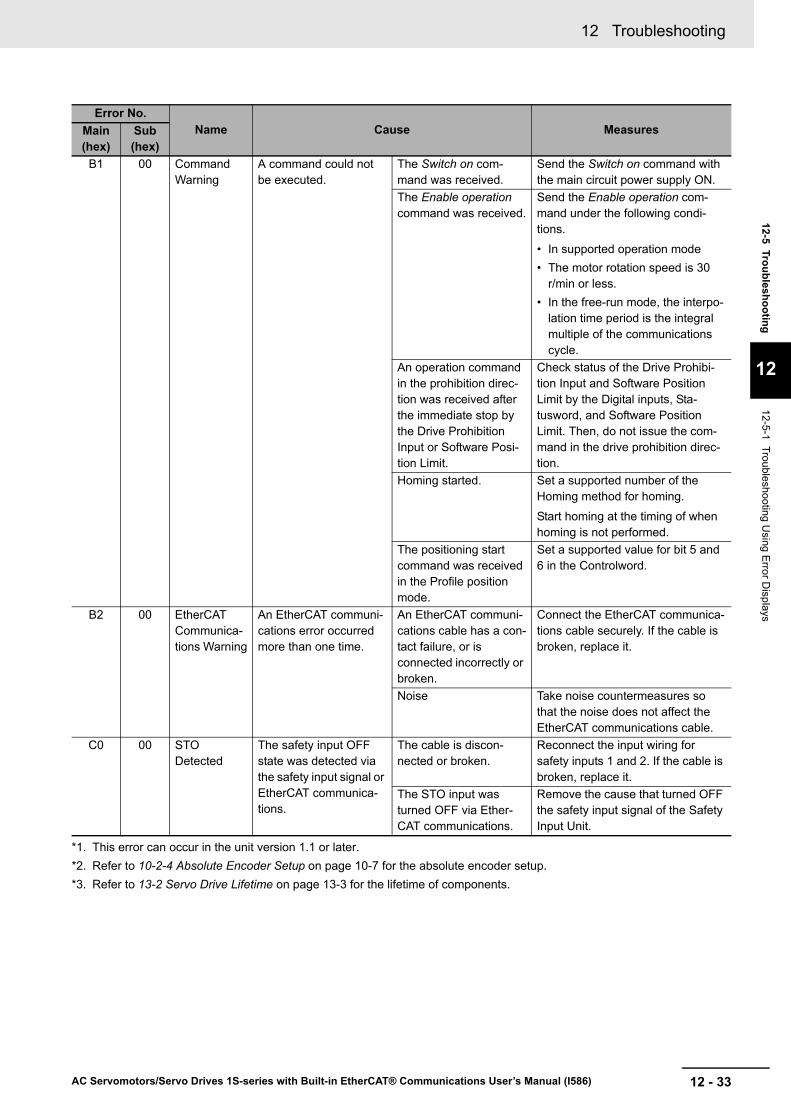
B1 00 Command Warning
A command could not be executed.
The Switch on com-mand was received.
Send the Switch on command with the main circuit power supply ON.
The Enable operation command was received.
Send the Enable operation com-mand under the following condi-tions.
• In supported operation mode• The motor rotation speed is 30
r/min or less.• In the free-run mode, the interpo-
lation time period is the integral multiple of the communications cycle.
An operation command in the prohibition direc-tion was received after the immediate stop by the Drive Prohibition Input or Software Posi-tion Limit.
Check status of the Drive Prohibi-tion Input and Software Position Limit by the Digital inputs, Sta-tusword, and Software Position Limit. Then, do not issue the com-mand in the drive prohibition direc-tion.
Homing started. Set a supported number of the Homing method for homing.
Start homing at the timing of when homing is not performed.
The positioning start command was received in the Profile position mode.
Set a supported value for bit 5 and 6 in the Controlword.
B2 00 EtherCAT Communica-tions Warning
An EtherCAT communi-cations error occurred more than one time.
An EtherCAT communi-cations cable has a con-tact failure, or is connected incorrectly or broken.
Connect the EtherCAT communica-tions cable securely. If the cable is broken, replace it.
Noise Take noise countermeasures so that the noise does not affect the EtherCAT communications cable.
C0 00 STO Detected
The safety input OFF state was detected via the safety input signal or EtherCAT communica-tions.
The cable is discon-nected or broken.
Reconnect the input wiring for safety inputs 1 and 2. If the cable is broken, replace it.
The STO input was turned OFF via Ether-CAT communications.
Remove the cause that turned OFF the safety input signal of the Safety Input Unit.
*1. This error can occur in the unit version 1.1 or later.*2. Refer to 10-2-4 Absolute Encoder Setup on page 10-7 for the absolute encoder setup.*3. Refer to 13-2 Servo Drive Lifetime on page 13-3 for the lifetime of components.
Error No.Name Cause MeasuresMain
(hex)Sub (hex)

12 Troubleshooting
12 - 34 AC Servomotors/Servo Drives 1S-series with Built-in EtherCAT® Communications User’s Manual (I586)
The AL status codes notify users of errors related to EtherCAT communications.
This section gives errors that 1S-series Servo Drives notify to the host controllers with AL status codes, as well as their causes and remedies.
12-5-2 Troubleshooting Using AL Status Codes
AL Status Code List
AL status code (hex) Name Cause Measures
0011 EtherCAT State Change Error
A communications state change command was received for which the current communications state could not be changed.
Check the command specifications for communications state transi-tions in the host controller and cor-rect host controller processing.
0012 EtherCAT Ille-gal State Change Error
An undefined communications state change command was received.
Check the command specifications for communications state transi-tions in the host controller and cor-rect host controller processing.
0013 Bootstrap State Transi-tion Request Error
The state transition to unsupported Bootstrap was requested by the EtherCAT master.
Check the EtherCAT master setting so that the EtherCAT master does not request the transition to Boot-strap.
0014 SII Verifica-tion Error
An error occurred in SII data of the EtherCAT slave communications controller.
Data was incorrectly over-written in the non-volatile memory of the EtherCAT slave communications controller.
If this event does not occur after you cycled the power supply, use the product continuously. It is sup-posed that a temporary error occurred due to a read error.
If this event occurs again, replace the Servo Drive.
Failure of the EtherCAT slave communications controller or false detec-tion
0016 Mailbox Set-ting Error
An incorrect mailbox setting of Sync Manager was detected.
Check the mailbox setting, and then download it to the EtherCAT master again.
001B Sync Man-ager WDT Error
PDO communications were interrupted for the allowable period or longer.
An EtherCAT communica-tions cable is discon-nected, loose, or broken
Connect the EtherCAT communica-tions cable securely.
Host controller error Check the operation of the host controller. Take appropriate countermeasures if there is a prob-lem.
001D RxPDO Set-ting Error
An RxPDO setting error was detected.
The RxPDO setting of EtherCAT master is incor-rect.
Correct the RxPDO setting accord-ing to the definition of ESI of Servo Drive, and then download it to the EtherCAT master again.
If this event occurs repeatedly after the download to the EtherCAT mas-ter, the Servo Drive is faulty. Replace the Servo Drive.
Servo Drive failure
12 - 35
12 Troubleshooting
AC Servomotors/Servo Drives 1S-series with Built-in EtherCAT® Communications User’s Manual (I586)
12-5 Troubleshooting
12
12-5-2 Troubleshooting Using A
L Status Codes
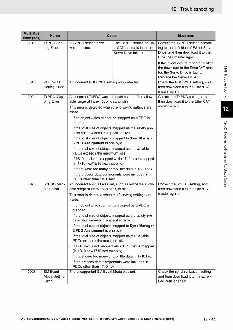
001E TxPDO Set-ting Error
A TxPDO setting error was detected.
The TxPDO setting of Eth-erCAT master is incorrect.
Correct the TxPDO setting accord-ing to the definition of ESI of Servo Drive, and then download it to the EtherCAT master again.
If this event occurs repeatedly after the download to the EtherCAT mas-ter, the Servo Drive is faulty. Replace the Servo Drive.
Servo Drive failure
001F PDO WDT Setting Error
An incorrect PDO WDT setting was detected. Check the PDO WDT setting, and then download it to the EtherCAT master again.
0024 TxPDO Map-ping Error
An incorrect TxPDO was set, such as out of the allow-able range of Index, Subindex, or size.
This error is detected when the following settings are made.
• If an object which cannot be mapped as a PDO is mapped
• If the total size of objects mapped as the safety pro-cess data exceeds the specified size
• If the total size of objects mapped to Sync Manager 3 PDO Assignment is one byte
• If the total size of objects mapped as the variable PDOs exceeds the maximum size
• If 1B10 hex is not mapped while 1710 hex is mapped (in 1710 hex/1B10 hex mapping)
• If there were too many or too little data in 1B10 hex• If the process data components were included in
PDOs other than 1B10 hex
Correct the TxPDO setting, and then download it to the EtherCAT master again.
0025 RxPDO Map-ping Error
An incorrect RxPDO was set, such as out of the allow-able range of Index, Subindex, or size.
This error is detected when the following settings are made.
• If an object which cannot be mapped as a PDO is mapped
• If the total size of objects mapped as the safety pro-cess data exceeds the specified size
• If the total size of objects mapped to Sync Manager 2 PDO Assignment is one byte
• If the total size of objects mapped as the variable PDOs exceeds the maximum size
• If 1710 hex is not mapped while 1B10 hex is mapped (in 1B10 hex/1710 hex mapping)
• If there were too many or too little data in 1710 hex• If the process data components were included in
PDOs other than 1710 hex
Correct the RxPDO setting, and then download it to the EtherCAT master again.
0028 SM Event Mode Setting Error
The unsupported SM Event Mode was set. Check the synchronization setting, and then download it to the Ether-CAT master again.
AL status code (hex) Name Cause Measures

12 Troubleshooting
12 - 36 AC Servomotors/Servo Drives 1S-series with Built-in EtherCAT® Communications User’s Manual (I586)
002C Synchroniza-tion Error
A signal for synchronous communications could not be detected.
Noise Take noise countermeasures if excessive noise affects the Ether-CAT communications cable.
Error of the EtherCAT slave communications controller
If this event occurs again after you cycled the power supply, replace the Servo Drive.
002D Synchroniza-tion Interrup-tion Error
Synchronization interrup-tion did not occur within the specified period.
Incorrect EtherCAT syn-chronization setting of the host controller.
Set the synchronization setting of the host controller according to the synchronization specifications for the EtherCAT slave.
Failure of the EtherCAT slave communications controller or false detec-tion
If this event does not occur after you cycled the power supply, use the product continuously. It is sup-posed that a temporary error occurred due to a read error. If this event occurs again, the Servo Drive is faulty. Replace the Servo Drive.
0030 DC Setting Error
A mistake was made in the DC Mode operation setting. Check the DC Mode setting, and then download it to the EtherCAT master again.
0034 Communica-tions Synchro-nization Error
Communications were not established consecutively because the synchroniza-tion with the EtherCAT Master could not be achieved.
The power supply to the host controller was inter-rupted during PDO com-munications.
Reset the error in the host control-ler. This event reports an error that was detected when the power sup-ply to the host controller was inter-rupted. It does not indicate that an error currently exists.
An EtherCAT communica-tions cable is discon-nected, loose, broken, or has a contact failure.
Connect the EtherCAT communica-tions cable securely. If the cable is broken, replace it.
Noise Take noise countermeasures if excessive noise affects the Ether-CAT communications cable.
0035 Synchroniza-tion Cycle Setting Error
When the DC mode was established, the cycle time was set to the inoperable value.
In the variable PDO map-ping, the maximum num-ber of objects you can map is specified as fol-lows: 6 for both RxPDO and TxPDO for the com-munication period of 125 µs, 10 for both RxPDO and TxPDO for other com-munication periods. An error occurs if you map a larger number of objects than that specified above.
This error is also detected in the following case: the cycle time is an integral multiple of 125 µs and is not 10 ms or lower.
The variable PDO map-ping is used, and the num-ber of objects is more than the maximum number of mapped objects for the cycle time.
Set the number of objects to a value smaller than the maximum number of mapped objects for the cycle time.
The cycle time setting is incorrect.
Correct the cycle time setting.
AL status code (hex) Name Cause Measures
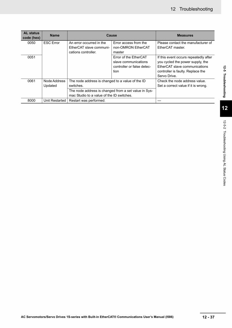
12 - 37
12 Troubleshooting
AC Servomotors/Servo Drives 1S-series with Built-in EtherCAT® Communications User’s Manual (I586)
12-5 Troubleshooting
12
12-5-2 Troubleshooting Using A
L Status Codes
0050 ESC Error An error occurred in the EtherCAT slave communi-cations controller.
Error access from the non-OMRON EtherCAT master
Please contact the manufacturer of EtherCAT master.
0051 Error of the EtherCAT slave communications controller or false detec-tion
If this event occurs repeatedly after you cycled the power supply, the EtherCAT slave communications controller is faulty. Replace the Servo Drive.
0061 Node Address Updated
The node address is changed to a value of the ID switches.
Check the node address value. Set a correct value if it is wrong.
The node address is changed from a set value in Sys-mac Studio to a value of the ID switches.
8000 Unit Restarted Restart was performed. ---
AL status code (hex) Name Cause Measures

12 Troubleshooting
12 - 38 AC Servomotors/Servo Drives 1S-series with Built-in EtherCAT® Communications User’s Manual (I586)
12-5-3 Troubleshooting Using the Operation State
Symptom Probable cause Check items MeasuresThe 7-segment dis-play does not light.
The control power is not sup-plied.
Check to see if the power sup-ply input is within the allowed power supply voltage range.
Supply the correct power sup-ply voltage.
Check to see if the power sup-ply input is wired correctly.
Wire correctly.
The ECAT ERR indi-cator flashes or lights.
A communications-related error occurred.
Refer to EtherCAT Communications Warning on page 12-9.
The L/A IN and L/A OUT indicators are OFF.
A link in the EtherCAT physical communications layer is not established.
Check to see if the communica-tions cable is connected cor-rectly.
Connect the communications cable correctly.
Check to see if the host control-ler started.
Start the host controller.
An error occurred. Read the error number and the error log.
Check the cause listed in 12-5-1 Troubleshooting Using Error Displays on page 12-14.
The Servo does not lock.
The power cable is not con-nected correctly.
Check to see if the motor power cable is connected properly.
Wire the motor power cable correctly.
The Servomotor power supply is not ON.
Check the main circuit wiring and power voltage.
Input the correct power and voltage for the main circuit.
Positive Drive Prohibition Input (POT) or Negative Drive Prohi-bition Input (NOT) is OFF.
• Check to see if the input for POT or NOT is OFF.
• Check the input of +24 VIN to CN1.
Turn ON POT and NOT. Input +24 VIN correctly.
The torque limit is set to 0. Check to see if the torque limits in the Positive torque limit value (60E0 hex) and the Neg-ative torque limit value (60E1 hex) are set to 0.
Set the maximum torque that you use for each of these objects.
The Servo Drive is in a safe state (STO).
Check the wiring of the safety input.
Wire correctly.
Communications with the Safety CPU Unit are not estab-lished.
When you use the STO func-tion via EtherCAT communica-tions, confirm that communications with the Safety CPU Unit are per-formed.
Make the settings for the Safety CPU Unit.
The Servo Drive is broken down.
--- Replace the Servo Drive.

12 - 39
12 Troubleshooting
AC Servomotors/Servo Drives 1S-series with Built-in EtherCAT® Communications User’s Manual (I586)
12-5 Troubleshooting
12
12-5-3 Troubleshooting Using the O
peration State
The Servo locks but the Servomotor does not rotate.
The host controller does not give a command.
For a position command, check to see if the speed and position are set to 0.
Enter position and speed data. Start the Servomotor.
The Servo Drive received a command but it is not accepted.
Check to see if the Servo Drive retains the object value for two communications cycles or more in Profile position mode (pp).
Set the Servo Drive so that it retains the object value for two communications cycles or more.
It is hard to determine if the Servomotor is rotating.
Check to see if the velocity command given by the host controller is too small.
Check the velocity command from the host controller.
The holding brake is operating. Check the Brake Interlock Out-put (BKIR) signal and the +24 VDC power supply.
Check to see if the holding brake on a Servomotor with brake is released when the Servo is locked.
The torque limits set in the Positive torque limit value (60E0 hex) and the Negative torque limit value (60E1 hex) are too small.
Check to see if the torque limits in objects 60E0 hex and 60E1 hex are set to a value close to 0.
Set the maximum torque that you use for each of these objects.
Positive Drive Prohibition Input (POT) or Negative Drive Prohi-bition Input (NOT) is OFF.
Check the ON/OFF state of the POT and NOT signals from the Sysmac Studio.
• Turn ON the POT and NOT signals.
• Disable them in the settings when the POT and NOT sig-nals are not used.
The motor power cable is wired incorrectly.
Check the wiring. Wire correctly.
The encoder cable is wired incorrectly.Power is not supplied. Check the power supply and
the 7-segment display.Turn ON the power.
Check the voltage between the power terminals.
Wire the power-ON circuit cor-rectly.
The Servo Drive is broken down.
--- Replace the Servo Drive.
The Servomotor oper-ates momentarily, but then it does not oper-ate after that.
The position commands given are too little.
Check the position data and the electronic gear ratio at the host controller.
Set the correct data.
The motor power cable is wired incorrectly.
Check the wiring of the motor power cable’s phases U, V, and W.
Wire correctly.
The encoder cable is wired incorrectly.
Check the encoder cable’s wir-ing.
Wire correctly.
The Servomotor rotates without a com-mand.
There are inputs of small val-ues in velocity control mode.
Check if there is an input in velocity control mode.
Set the velocity command to 0. Alternatively, change the mode to position control mode.
The motor power cable is wired incorrectly.
Check the wiring. Wire correctly.
When the runaway detection function is enabled, the Servomotor rotates without a command.
The Servomotor power cable is wired incorrectly, and condi-tions under which the runaway detection function cannot work are satisfied.
Check the wiring. Wire correctly.
Symptom Probable cause Check items Measures
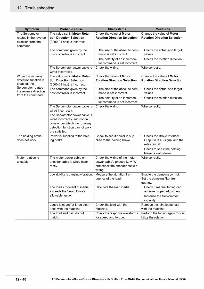
12 Troubleshooting
12 - 40 AC Servomotors/Servo Drives 1S-series with Built-in EtherCAT® Communications User’s Manual (I586)
The Servomotor rotates in the reverse direction from the command.
The value set in Motor Rota-tion Direction Selection (3000-01 hex) is incorrect.
Check the value of Motor Rotation Direction Selection.
Change the value of Motor Rotation Direction Selection.
The command given by the host controller is incorrect.
• The size of the absolute com-mand is set incorrect.
• The polarity of an incremen-tal command is set incorrect.
• Check the actual and target values.
• Check the rotation direction.
The Servomotor power cable is wired incorrectly.
Check the wiring. Wire correctly.
When the runaway detection function is enabled, the Servomotor rotates in the reverse direction from the command.
The value set in Motor Rota-tion Direction Selection (3000-01 hex) is incorrect.
Check the value of Motor Rotation Direction Selection.
Change the value of Motor Rotation Direction Selection.
The command given by the host controller is incorrect.
• The size of the absolute com-mand is set incorrect.
• The polarity of an incremen-tal command is set incorrect.
• Check the actual and target values.
• Check the rotation direction.
The Servomotor power cable is wired incorrectly.
Check the wiring. Wire correctly.
The Servomotor power cable is wired incorrectly, and condi-tions under which the runaway detection function cannot work are satisfied.
The holding brake does not work.
Power is supplied to the hold-ing brake.
Check to see if power is sup-plied to the holding brake.
• Check the Brake Interlock Output (BKIR) signal and the relay circuit.
• Check to see if the holding brake is worn down.
Motor rotation is unstable.
The motor power cable or encoder cable is wired incor-rectly.
Check the wiring of the motor power cable’s phases U, V, W and check the encoder cable’s wiring.
Wire correctly.
Low rigidity is causing vibration. Measure the vibration fre-quency of the load.
Enable the damping control. Set the damping filter fre-quency.
The load’s moment of inertia exceeds the Servo Drive’s allowable value.
Calculate the load inertia. • Check if manual tuning can achieve proper adjustment.
• Increase the Servomotor capacity.
Loose joint and/or large clear-ance with the machine.
Check the joint with the machine.
Remove the joint looseness with the machine.
The load and gain do not match.
Check the response waveforms for speed and torque.
Perform the tuning again to sta-bilize the rotation.
Symptom Probable cause Check items Measures

12 - 41
12 Troubleshooting
AC Servomotors/Servo Drives 1S-series with Built-in EtherCAT® Communications User’s Manual (I586)
12-5 Troubleshooting
12
12-5-3 Troubleshooting Using the O
peration State
The Servomotor is overheating.
The ambient temperature is too high.
Check to see if the ambient temperature around the Servo-motor is over 40°C.
• Lower the ambient tempera-ture around the Servomotor to 40°C or less. (Use a fan or air conditioner.)
• Lower the load ratio.The heat radiation condition for the Servomotor is inappropri-ate.
• Check to see if the specified radiation conditions are observed.
• For a Servomotor with a brake, check the load ratio.
• Improve the radiation condi-tions.
• Reduce the load.• Improve ventilation.
The Servomotor is overloaded. Check the torque with the Sys-mac Studio.
• Decrease the acceleration and deceleration rates.
• Lower the speed and check the load.
The Servomotor vibrates during rotation.
The machine position is misaligned.
The coupling of the motor shaft and the machine is abnormal.
Check to see if the coupling of the Servomotor and the machine is misaligned.
• Tighten the coupling again.• Replace the coupling with a
coupling that has no loose-ness.
The host controller gave a deceleration stop command.
Check the control ladder pro-gram in the host controller.
Review the control in the host controller.
The gain is wrong. --- Check if manual tuning can achieve proper adjustment.
The load inertia is too large. • Check the load inertia.• Check the Servomotor rota-
tion speed.
• Review the load inertia.• Replace the Servomotor and
Servo Drive with proper ones.
The power supply was turned ON while the encoder multi-rotation exceeded the limit value.
Check Encoder - Multi-rotation Data.
Perform the operation within the multi-rotation range.
The command value from the host controller is not correct.
Check the control ladder pro-gram and settings in the host controller.
Review the control and settings in the host controller.
The home position was shifted. • Check the home position of the absolute encoder.
• Check whether homing is performed normally.
• Adjust the mechanical home and home position of the absolute encoder.
• Change the setting or input signals so that the correct home position can be defined during homing.
The set values of the Servo Drive do not match the machine.
Check the settings of gear ratio, gain, maximum torque, etc.
Adjust the set values so that they match the machine.
The Servomotor does not stop or is hard to stop even if the Servo is turned OFF while the Servomotor is rotating.
The load inertia is too large. • Check the load inertia.• Check the Servomotor rota-
tion speed.
• Review the load inertia.• Replace the Servomotor and
Servo Drive with proper ones.
The dynamic brake is disabled. Check if the dynamic brake is disabled or broken.
• Enable the dynamic brake, if it is disabled.
• Replace the dynamic brake if it is broken.
Symptom Probable cause Check items Measures
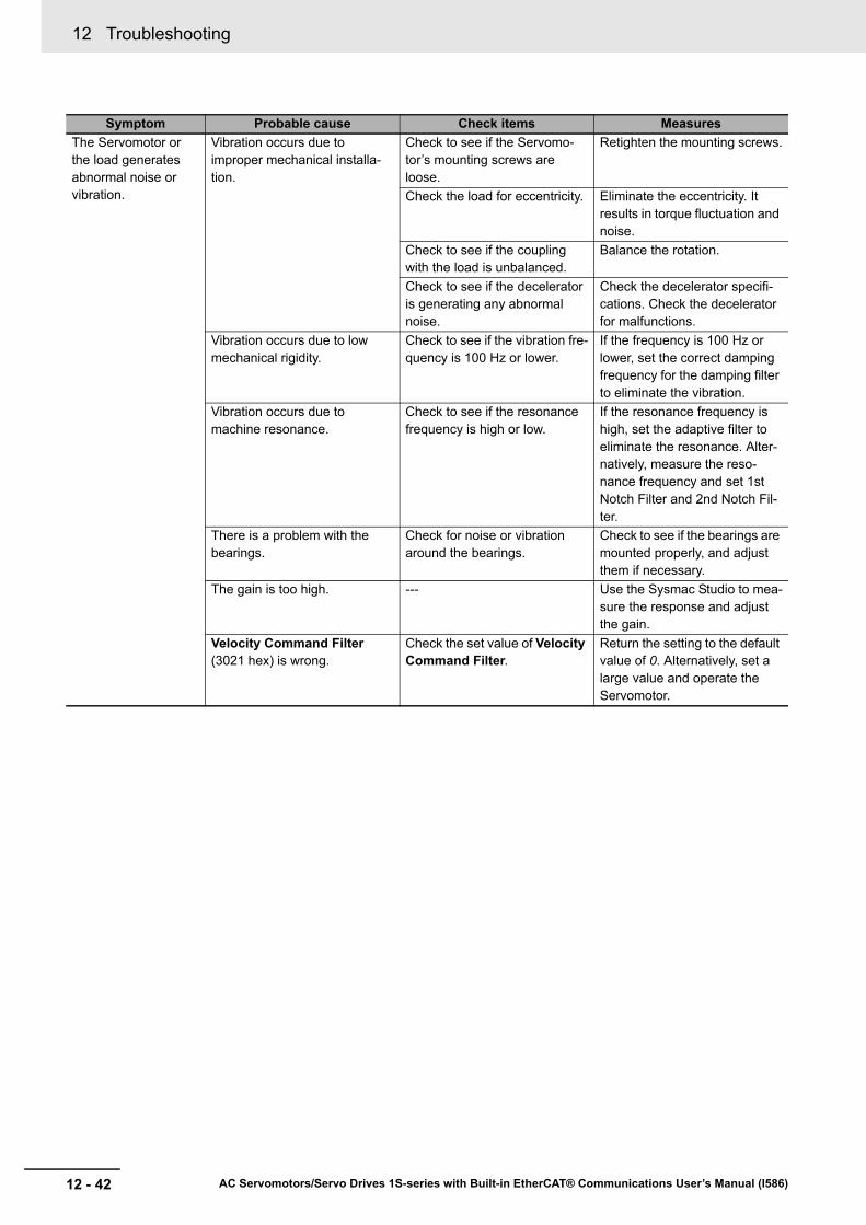
12 Troubleshooting
12 - 42 AC Servomotors/Servo Drives 1S-series with Built-in EtherCAT® Communications User’s Manual (I586)
The Servomotor or the load generates abnormal noise or vibration.
Vibration occurs due to improper mechanical installa-tion.
Check to see if the Servomo-tor’s mounting screws are loose.
Retighten the mounting screws.
Check the load for eccentricity. Eliminate the eccentricity. It results in torque fluctuation and noise.
Check to see if the coupling with the load is unbalanced.
Balance the rotation.
Check to see if the decelerator is generating any abnormal noise.
Check the decelerator specifi-cations. Check the decelerator for malfunctions.
Vibration occurs due to low mechanical rigidity.
Check to see if the vibration fre-quency is 100 Hz or lower.
If the frequency is 100 Hz or lower, set the correct damping frequency for the damping filter to eliminate the vibration.
Vibration occurs due to machine resonance.
Check to see if the resonance frequency is high or low.
If the resonance frequency is high, set the adaptive filter to eliminate the resonance. Alter-natively, measure the reso-nance frequency and set 1st Notch Filter and 2nd Notch Fil-ter.
There is a problem with the bearings.
Check for noise or vibration around the bearings.
Check to see if the bearings are mounted properly, and adjust them if necessary.
The gain is too high. --- Use the Sysmac Studio to mea-sure the response and adjust the gain.
Velocity Command Filter (3021 hex) is wrong.
Check the set value of Velocity Command Filter.
Return the setting to the default value of 0. Alternatively, set a large value and operate the Servomotor.
Symptom Probable cause Check items Measures
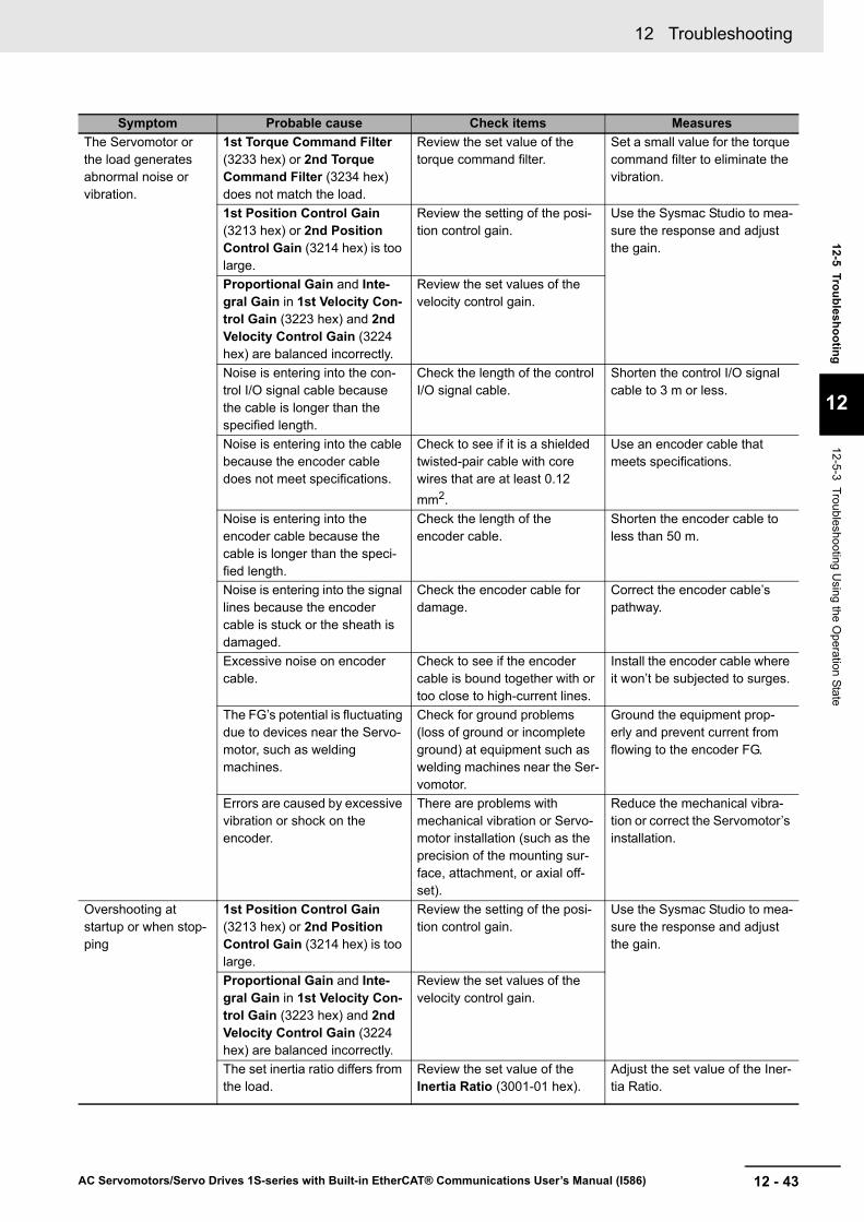
12 - 43
12 Troubleshooting
AC Servomotors/Servo Drives 1S-series with Built-in EtherCAT® Communications User’s Manual (I586)
12-5 Troubleshooting
12
12-5-3 Troubleshooting Using the O
peration State
The Servomotor or the load generates abnormal noise or vibration.
1st Torque Command Filter (3233 hex) or 2nd Torque Command Filter (3234 hex) does not match the load.
Review the set value of the torque command filter.
Set a small value for the torque command filter to eliminate the vibration.
1st Position Control Gain (3213 hex) or 2nd Position Control Gain (3214 hex) is too large.
Review the setting of the posi-tion control gain.
Use the Sysmac Studio to mea-sure the response and adjust the gain.
Proportional Gain and Inte-gral Gain in 1st Velocity Con-trol Gain (3223 hex) and 2nd Velocity Control Gain (3224 hex) are balanced incorrectly.
Review the set values of the velocity control gain.
Noise is entering into the con-trol I/O signal cable because the cable is longer than the specified length.
Check the length of the control I/O signal cable.
Shorten the control I/O signal cable to 3 m or less.
Noise is entering into the cable because the encoder cable does not meet specifications.
Check to see if it is a shielded twisted-pair cable with core wires that are at least 0.12 mm2.
Use an encoder cable that meets specifications.
Noise is entering into the encoder cable because the cable is longer than the speci-fied length.
Check the length of the encoder cable.
Shorten the encoder cable to less than 50 m.
Noise is entering into the signal lines because the encoder cable is stuck or the sheath is damaged.
Check the encoder cable for damage.
Correct the encoder cable’s pathway.
Excessive noise on encoder cable.
Check to see if the encoder cable is bound together with or too close to high-current lines.
Install the encoder cable where it won’t be subjected to surges.
The FG’s potential is fluctuating due to devices near the Servo-motor, such as welding machines.
Check for ground problems (loss of ground or incomplete ground) at equipment such as welding machines near the Ser-vomotor.
Ground the equipment prop-erly and prevent current from flowing to the encoder FG.
Errors are caused by excessive vibration or shock on the encoder.
There are problems with mechanical vibration or Servo-motor installation (such as the precision of the mounting sur-face, attachment, or axial off-set).
Reduce the mechanical vibra-tion or correct the Servomotor’s installation.
Overshooting at startup or when stop-ping
1st Position Control Gain (3213 hex) or 2nd Position Control Gain (3214 hex) is too large.
Review the setting of the posi-tion control gain.
Use the Sysmac Studio to mea-sure the response and adjust the gain.
Proportional Gain and Inte-gral Gain in 1st Velocity Con-trol Gain (3223 hex) and 2nd Velocity Control Gain (3224 hex) are balanced incorrectly.
Review the set values of the velocity control gain.
The set inertia ratio differs from the load.
Review the set value of the Inertia Ratio (3001-01 hex).
Adjust the set value of the Iner-tia Ratio.
Symptom Probable cause Check items Measures
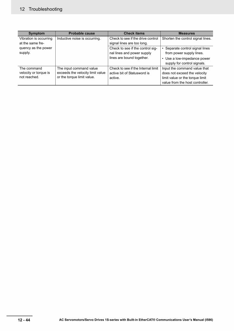
12 Troubleshooting
12 - 44 AC Servomotors/Servo Drives 1S-series with Built-in EtherCAT® Communications User’s Manual (I586)
Vibration is occurring at the same fre-quency as the power supply.
Inductive noise is occurring. Check to see if the drive control signal lines are too long.
Shorten the control signal lines.
Check to see if the control sig-nal lines and power supply lines are bound together.
• Separate control signal lines from power supply lines.
• Use a low-impedance power supply for control signals.
The command velocity or torque is not reached.
The input command value exceeds the velocity limit value or the torque limit value.
Check to see if the Internal limit active bit of Statusword is active.
Input the command value that does not exceed the velocity limit value or the torque limit value from the host controller.
Symptom Probable cause Check items Measures