AC Modular Power System (Front Cover) - Infi 90 Infi90 Documentation/AC...I-E96-506B1 Preface The AC...
98
® ® Process Control and Automation Solutions from Elsag Bailey Group E96-506 AC Modular Power System
-
Upload
truongtram -
Category
Documents
-
view
219 -
download
1
Transcript of AC Modular Power System (Front Cover) - Infi 90 Infi90 Documentation/AC...I-E96-506B1 Preface The AC...

®®
E96-506
AC Modular Power System
Process Control andAutomation Solutionsfrom Elsag Bailey Group

WARNING notices as used in this instruction apply to hazards or unsafe practices that could result inpersonal injury or death.
CAUTION notices apply to hazards or unsafe practices that could result in property damage.
NOTES highlight procedures and contain information that assists the operator in understanding theinformation contained in this instruction.
WARNING
INSTRUCTION MANUALSDO NOT INSTALL, MAINTAIN, OR OPERATE THIS EQUIPMENT WITHOUT READING, UNDERSTANDING,AND FOLLOWING THE PROPER Elsag Bailey INSTRUCTIONS AND MANUALS; OTHERWISE, INJURY ORDAMAGE MAY RESULT.
RADIO FREQUENCY INTERFERENCEMOST ELECTRONIC EQUIPMENT IS INFLUENCED BY RADIO FREQUENCY INTERFERENCE (RFI). CAU-TION SHOULD BE EXERCISED WITH REGARD TO THE USE OF PORTABLE COMMUNICATIONS EQUIP-MENT IN THE AREA AROUND SUCH EQUIPMENT. PRUDENT PRACTICE DICTATES THAT SIGNSSHOULD BE POSTED IN THE VICINITY OF THE EQUIPMENT CAUTIONING AGAINST THE USE OF POR-TABLE COMMUNICATIONS EQUIPMENT.
POSSIBLE PROCESS UPSETSMAINTENANCE MUST BE PERFORMED ONLY BY QUALIFIED PERSONNEL AND ONLY AFTER SECURINGEQUIPMENT CONTROLLED BY THIS PRODUCT. ADJUSTING OR REMOVING THIS PRODUCT WHILE IT ISIN THE SYSTEM MAY UPSET THE PROCESS BEING CONTROLLED. SOME PROCESS UPSETS MAYCAUSE INJURY OR DAMAGE.
AVERTISSEMENT
MANUELS D’OPÉRATIONNE PAS METTRE EN PLACE, RÉPARER OU FAIRE FONCTIONNER L’ÉQUIPEMENT SANS AVOIR LU,COMPRIS ET SUIVI LES INSTRUCTIONS RÉGLEMENTAIRES DE Elsag Bailey . TOUTE NÉGLIGENCE ÀCET ÉGARD POURRAIT ÊTRE UNE CAUSE D’ACCIDENT OU DE DÉFAILLANCE DU MATÉRIEL.
PERTURBATIONS PAR FRÉQUENCE RADIOLA PLUPART DES ÉQUIPEMENTS ÉLECTRONIQUES SONT SENSIBLES AUX PERTURBATIONS PARFRÉQUENCE RADIO. DES PRÉCAUTIONS DEVRONT ÊTRE PRISES LORS DE L’UTILISATION DU MATÉ-RIEL DE COMMUNICATION PORTATIF. LA PRUDENCE EXIGE QUE LES PRÉCAUTIONS À PRENDREDANS CE CAS SOIENT SIGNALÉES AUX ENDROITS VOULUS DANS VOTRE USINE.
PERTURBATIONS DU PROCÉDÉL’ENTRETIEN DOIT ÊTRE ASSURÉ PAR UNE PERSONNE QUALIFIÉE EN CONSIDÉRANT L’ASPECTSÉCURITAIRE DES ÉQUIPEMENTS CONTRÔLÉS PAR CE PRODUIT. L’AJUSTEMENT ET/OU L’EXTRAC-TION DE CE PRODUIT PEUT OCCASIONNER DES À-COUPS AU PROCÉDÉ CONTRÔLE LORSQU’IL ESTINSÉRÉ DANS UNE SYSTÈME ACTIF. CES À-COUPS PEUVENT ÉGALEMENT OCCASIONNER DESBLESSURES OU DES DOMMAGES MATÉREILS.
NOTICE
The information contained in this document is subject to change without notice.
Elsag Bailey, its affiliates, employees, and agents, and the authors and contributors to this publication specif-ically disclaim all liabilities and warranties, express and implied (including warranties of merchantability andfitness for a particular purpose), for the accuracy, currency, completeness, and/or reliability of the informationcontained herein and/or for the fitness for any particular use and/or for the performance of any material and/or equipment selected in whole or part with the user of/or in reliance upon information contained herein.Selection of materials and/or equipment is at the sole risk of the user of this publication.
This document contains proprietary information of Elsag Bailey, Elsag Bailey Process Automation, andis issued in strict confidence. Its use, or reproduction for use, for the reverse engineering, developmentor manufacture of hardware or software described herein is prohibited. No part of this document may bephotocopied or reproduced without the prior written consent of Elsag Bailey.

I-E96-506B
Preface
The AC Modular Power System supplies system and I/O powerto the components within an INFI 90® system cabinet. Thismanual provides information on the IEPAS02 and IEPAF02Power Modules and their related system hardware. Relatedhardware includes the IEPEP01, IEPEP02 and IEPEP03 PowerEntry Panels, IEMMU01 and IEMMU02 Module Mounting Units,and IEPMU01 and IEPMU02 Power Mounting Units. The infor-mation in this manual includes a procedure for sizing the powersystem, installation instructions, operating procedures, trouble-shooting, maintenance and repair/replacement procedures.
The IEPAS02 and IEPAF02 AC Power Modules supersede theIEPAS01 and IEPAF01 AC Power Modules and are compatiblereplacements. Refer to Appendix E for more information.
® INFI 90 is a registered trademark of Elsag Bailey Process Automation.
1

®
List of Effective Pages
Total number of pages in this instruction is 95, consisting of the following:
Page No. Change Date
Preface OriginalList of Effective Pages Original
iii through ix Original1-1 through 1-7 Original2-1 through 2-7 Original3-1 through 3-17 Original4-1 through 4-4 Original5-1 through 5-7 Original6-1 through 6-8 Original7-1 through 7-6 Original8-1 OriginalA-1 through A-2 OriginalB-1 through B-10 OriginalC-1 through C-5 OriginalD-1 through D-8 OriginalD-1 through E-2 Original
Index-1 through Index-2 Original
When an update is received, insert the latest changed pages and dispose of the super-seded pages.
NOTE: On an update page, the changed text or table is indicated by a vertical bar in the outer mar-gin of the page adjacent to the changed area. A changed figure is indicated by a vertical bar in theouter margin next to the figure caption. The date the update was prepared will appear beside thepage number.
I-E96-506B1
I-E96-506B
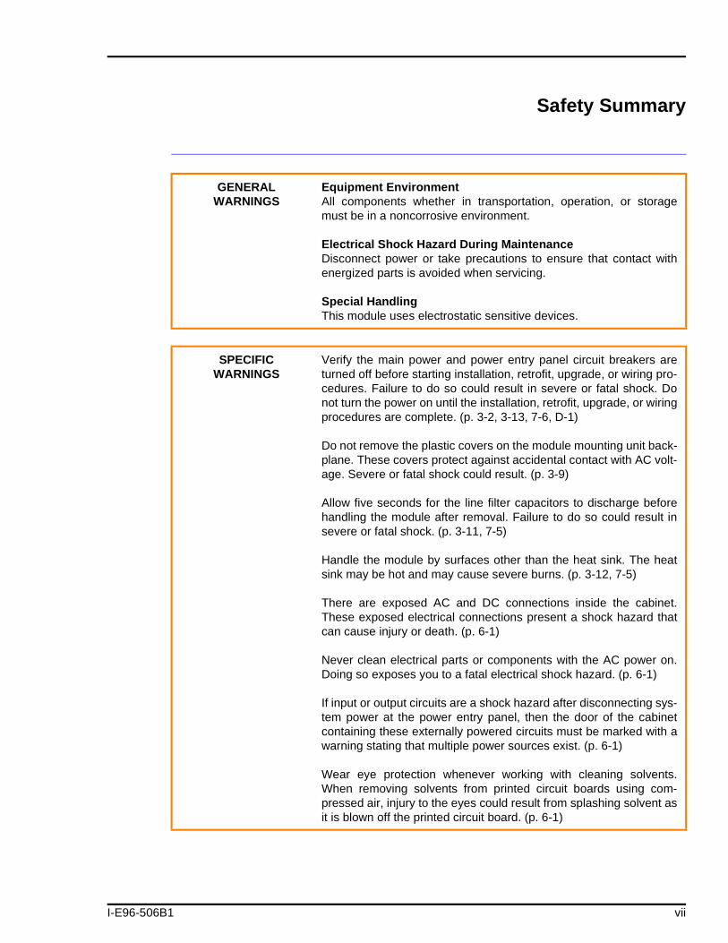
Safety Summary
GENERALWARNINGS
Equipment EnvironmentAll components whether in transportation, operation, or storagemust be in a noncorrosive environment.
Electrical Shock Hazard During MaintenanceDisconnect power or take precautions to ensure that contact withenergized parts is avoided when servicing.
Special HandlingThis module uses electrostatic sensitive devices.
SPECIFICWARNINGS
Verify the main power and power entry panel circuit breakers areturned off before starting installation, retrofit, upgrade, or wiring pro-cedures. Failure to do so could result in severe or fatal shock. Donot turn the power on until the installation, retrofit, upgrade, or wiringprocedures are complete. (p. 3-2, 3-13, 7-6, D-1)
Do not remove the plastic covers on the module mounting unit back-plane. These covers protect against accidental contact with AC volt-age. Severe or fatal shock could result. (p. 3-9)
Allow five seconds for the line filter capacitors to discharge beforehandling the module after removal. Failure to do so could result insevere or fatal shock. (p. 3-11, 7-5)
Handle the module by surfaces other than the heat sink. The heatsink may be hot and may cause severe burns. (p. 3-12, 7-5)
There are exposed AC and DC connections inside the cabinet.These exposed electrical connections present a shock hazard thatcan cause injury or death. (p. 6-1)
Never clean electrical parts or components with the AC power on.Doing so exposes you to a fatal electrical shock hazard. (p. 6-1)
If input or output circuits are a shock hazard after disconnecting sys-tem power at the power entry panel, then the door of the cabinetcontaining these externally powered circuits must be marked with awarning stating that multiple power sources exist. (p. 6-1)
Wear eye protection whenever working with cleaning solvents.When removing solvents from printed circuit boards using com-pressed air, injury to the eyes could result from splashing solvent asit is blown off the printed circuit board. (p. 6-1)
1 vii

Safety Summary (continued)
®
Sommaire de Sécurité
SPECIFIC CAUTIONS Verify the line voltage select switch is properly configured beforeenergizing the power entry panel. Failure to do so could perma-nently damage the PFI circuit board by exposing it to improper inputvoltage levels. (p. 3-12)
AVERTISSEMENTD'ORDREGENERAL
Environment de l'equipmentNe pas soumettre les composants a une atmosphere corrosive lorsdu transport, de l'entreposage cu de l'utilisation.
Risques de chocs electriques lor de l'entretienS'assurer de debrancher l'alimentation ou de prendre les precau-tions necessaires a eviter tout contact avec des composants sourstension lors de l'entretien.
Precautions de manutentionCe module contient des composantes sensibles aux dechargeselectro-statiques.
AVERTISSEMENTD'ORDRE
SPECIFIQUE
Assurez-vous que le disjoncteur d'alimentation principal et le dis-joncteur de panneau d'entrée des alimentatoins sont éteints avantde procéder à l'installation, à la mise à jour, à l'extension ou aucâblage, dans le but d'éviter les chocs sérieux et même mortels. Nerétablissez pas l'alimentation tant que ces procédures ne sont pasterminées. (p. 3-2, 3-13, 7-6, D-1)
Ne retirez pas les couvercles de plastique situés sur le panneauarrière du châssis de montage des modules. Ces couvercles con-stituent une protection contre les contacts accidentels avec la ten-sion c.a., qui risquent de provoquer des chocs sérieux et mêmemortels. (p. 3-9)
Après avoir retiré le module, laissez les condensateurs de filtresantiparasites se décharger pendant cinq secondes avant demanipuler celui-ci, afin d'éviter les chocs sérieux et même mortels.(p. 3-12, 7-5)
viii I-E96-506B1

I-E96-506B
Sommaire de Sécurité (suite)
AVERTISSEMENTD'ORDRE
SPECIFIQUE(suite)
Le module diot être manipulé à l'aide de surfaces autres que le dis-sipatour thermique. Ce dernier resque d'être chaud et de provoquerdes brûlures sérieuses. (p. 3-12, 7-5)
Cette armoire comporte des connexions c.a. et c.c. dénudées. Cesconnexions électriques présentent un danger d'électrocution pou-vant entraîner des blessures ou la mort. (p. 6-1)
Il ne faut jamais nettoyer des piècesou des composants électriqueslorsqu'ils sont sous tension. Cedi présente un risque d'électrocutionfatale. (p. 6-1)
Si des circuits d'entrée ou de sortie sont alimentés à partir desources externes, ils présentent un risque de choc électrique mêmelorsque l'alimentation du système est débranchée du panneaud'entrée l'alimentation. Le cas échéant, un avertissement signalantla présence de sources d'alimentation multiples doit être apposé surla porte de l'armoire. (p. 6-1)
Portez toujours des lunettes de protection lorsque vous utilisez dessolvants de nettoyage. L'aircomprimé servant à enlever le solvantdes cartes de circuits imprimés provoque des éclaboussures qui ris-quent d'atteindre les yeux. (p. 6-1)
ATTENTION D'ORDRE SPECIFIQUE
Assurez-vous que l'interrupteur de sélection de la tension de ligneest adéquatement configuré avant de mettre sous tension le pan-neau d'entrée des alimentations. Toute négligence à cet égard ris-que d'endommager de facon permanente la carte de détection descoupures d'alimentation (PFI) en l'exposant à des niveauxinadéquats de tension d'entrée. (p. 3-12)
1 ix
Table of Contents
I-E96-506B
Page
SECTION 1 - INTRODUCTION....................................................................................................1-1OVERVIEW ..................................................................................................................1-1HARDWARE DESCRIPTION..........................................................................................1-1
Power Entry Panel..................................................................................................1-1Fan Assembly ........................................................................................................1-1Power Modules.......................................................................................................1-2Power Mounting Units............................................................................................1-2Module Mounting Units .........................................................................................1-2
USER QUALIFICATIONS ..............................................................................................1-2INSTRUCTION CONTENT .............................................................................................1-2HOW TO USE THIS MANUAL .......................................................................................1-3REFERENCE DOCUMENTS..........................................................................................1-4NOMENCLATURE ........................................................................................................1-4GLOSSARY OF TERMS AND ABBREVIATIONS .............................................................1-4SPECIFICATIONS.........................................................................................................1-5
SECTION 2 - DESCRIPTION AND OPERATION........................................................................2-1INTRODUCTION...........................................................................................................2-1POWER DISTRIBUTION................................................................................................2-2POWER ENTRY PANEL.................................................................................................2-2
IEPEP01 and IEPEP02 Panels ................................................................................2-2IEPEP03 Panel .......................................................................................................2-2AC Transfer Module ...............................................................................................2-3Bus Monitor Module ..............................................................................................2-3
FAN ASSEMBLY ...........................................................................................................2-4MODULE MOUNTING UNIT..........................................................................................2-4POWER MOUNTING UNITS ..........................................................................................2-4POWER MODULES ......................................................................................................2-4STATUS SIGNALS ........................................................................................................2-5
Power System Status .............................................................................................2-5Bus Voltage Status ................................................................................................2-6Power Module Status .............................................................................................2-6Customer Alarm Outputs .......................................................................................2-7
SECTION 3 - INSTALLATION .....................................................................................................3-1INTRODUCTION...........................................................................................................3-1UNPACKING AND INSPECTION ....................................................................................3-1
Special Handling....................................................................................................3-1General Handling...................................................................................................3-2
IEPEP03 POWER ENTRY PANEL WIRING .....................................................................3-2AC Transfer Module ...............................................................................................3-5Bus Monitor Module ..............................................................................................3-7Fan Assembly ........................................................................................................3-9Power Modules.......................................................................................................3-9
IEPEP01 AND IEPEP02 POWER ENTRY PANEL WIRING .............................................3-12IEPMU01 AND IEPMU02 POWER MOUNTING UNIT INSTALLATION ...........................3-13
Required Tools .....................................................................................................3-14Installation in the INFI 90 Cabinet .......................................................................3-14Wiring Instructions ..............................................................................................3-14
SECTION 4 - OPERATING PROCEDURES................................................................................4-1INTRODUCTION...........................................................................................................4-1
1 iii
Table of Contents (continued)
®
Page
SECTION 4 - OPERATING PROCEDURES (continued)LED INDICATORS........................................................................................................ 4-1
AC Transfer Module............................................................................................... 4-1Bus Monitor Module .............................................................................................. 4-1Power Module ........................................................................................................ 4-2
REMOVING ATM OR BMM MODULES DURING OPERATION ....................................... 4-3RECOMMENDED START-UP PROCEDURES ................................................................ 4-3
SECTION 5 - TROUBLESHOOTING...........................................................................................5-1INTRODUCTION .......................................................................................................... 5-1TROUBLESHOOTING FLOWCHARTS ........................................................................... 5-1
IEPEP01 and IEPEP02 Systems ............................................................................. 5-1IEPEP03 Systems .................................................................................................. 5-1
SECTION 6 - MAINTENANCE.....................................................................................................6-1INTRODUCTION .......................................................................................................... 6-1PREVENTIVE MAINTENANCE SCHEDULE................................................................... 6-2EQUIPMENT REQUIRED ............................................................................................. 6-3PREVENTIVE MAINTENANCE PROCEDURES .............................................................. 6-3
Cabinet Filter Cleaning/Replacement .................................................................... 6-3Checking Connections ........................................................................................... 6-4Checking Power Module Outputs ........................................................................... 6-5
Checking Bus Voltages on IEPEP01 and IEPEP02 Systems .............................. 6-5Checking Bus Voltages on IEPEP03 Systems ................................................... 6-5
Power Entry Panel Inspection and Check ............................................................... 6-6Printed Circuit Board Cleaning .............................................................................. 6-6
General Cleaning and Washing........................................................................ 6-7Edge Connector Cleaning ................................................................................ 6-7Cleaning Female Edge Connectors ................................................................... 6-8
SECTION 7 - REPAIR/REPLACEMENT PROCEDURES ...........................................................7-1INTRODUCTION .......................................................................................................... 7-1SPARE PARTS.............................................................................................................. 7-1AC TRANSFER MODULE REPLACEMENT .................................................................... 7-2BUS MONITOR MODULE REPLACEMENT ................................................................... 7-3FAN ASSEMBLY .......................................................................................................... 7-3
Fuse Replacement ................................................................................................. 7-3Fan Assembly Replacement ................................................................................... 7-3
POWER MODULE ........................................................................................................ 7-4Power Module Replacement ................................................................................... 7-4Power Module Fuse Replacement ........................................................................... 7-5
POWER ENTRY PANEL REPLACEMENT ....................................................................... 7-6
SECTION 8 - SUPPORT SERVICES...........................................................................................8-1INTRODUCTION .......................................................................................................... 8-1REPLACEMENT PARTS AND ORDERING INFORMATION ............................................. 8-1TRAINING.................................................................................................................... 8-1TECHNICAL DOCUMENTATION................................................................................... 8-1
APPENDIX A - QUICK REFERENCE GUIDE ............................................................................ A-1INTRODUCTION ..........................................................................................................A-1
iv I-E96-506B1
I-E96-506B
Table of Contents (continued)
Page
APPENDIX B - MODULE POWER REQUIREMENTS ............................................................... B-1INTRODUCTION.......................................................................................................... B-1CALCULATING CURRENT REQUIREMENTS................................................................ B-1SIZING THE MODULAR POWER SYSTEM.................................................................... B-5
Sizing Systems with IEPAS02 Modules Only .......................................................... B-5System Calculation Example Using IEPAS02 Modules Only ................................... B-6For Systems Using Both IEPAS02 and IEPAF02 Modules ...................................... B-7System Calculation Example Using IEPAS02 and IEPAF02 Modules ...................... B-9
MAXIMUM POWER ENTRY PANEL CURRENT DRAW................................................. B-10
APPENDIX C - WIRING DIAGRAMS.......................................................................................... C-1INTRODUCTION.......................................................................................................... C-1
APPENDIX D - RETROFITTING THE MODULAR POWER SYSTEM....................................... D-1INTRODUCTION.......................................................................................................... D-1NETWORK 90 POWER SYSTEM REMOVAL ................................................................. D-2
Required Tools ...................................................................................................... D-2Power Entry Panel Removal................................................................................... D-2I/O Power Panel Removal ...................................................................................... D-3Module Power Panel Removal ................................................................................ D-3Fan Assembly Removal ......................................................................................... D-4Installing the INFI 90 Power System ...................................................................... D-4Wiring the INFI 90 Power System .......................................................................... D-5
APPENDIX E - IEPAS01/IEPAF01 POWER MODULE REPLACEMENT.................................. E-1INTRODUCTION.......................................................................................................... E-1REPLACING POWER MODULES .................................................................................. E-1POWER SYSTEM SIZING............................................................................................. E-1LOAD SHARING .......................................................................................................... E-1SYSTEM EFFECTS ON MODULE LEDS ....................................................................... E-2
List of Figures
No. Title Page
2-1. Modular Power System Architecture .......................................................................2-12-2. Power Distribution to the IEPAS02 System Power Module ......................................2-52-3. IEPAS02 Module Converter and Status Circuitry ....................................................2-62-4. Status Signal Block Diagram..................................................................................2-73-1. Circuit Breakers CB1/CB2 ....................................................................................3-33-2. AC Transfer Module, Switch S1 ..............................................................................3-53-3. IEPEP03 Power Entry Panel, Rear View ..................................................................3-63-4. Bus Monitor Module, Switch S1 and Jumpers J1 through J8 .................................3-73-5. Recommended Power Module Layout for Module Mounting Unit ...........................3-103-6. IEPAF02 and IEPAS02 Power Module Board Layout .............................................3-113-7. Rear of IEPEP01 and IEPEP02 Power Entry Panels ...............................................3-133-8. Heat Shrink Tubing for 5 VDC Connection ...........................................................3-153-9. Heat Shrink Tubing for 24 VDC Connection .........................................................3-16
1 v
List of Figures (continued)
No. Title Page
®
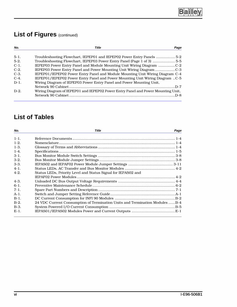
5-1. Troubleshooting Flowchart, IEPEP01 and IEPEP02 Power Entry Panels ................. 5-25-2. Troubleshooting Flowchart, IEPEP03 Power Entry Panel (Page 1 of 3) .................... 5-5C-1. IEPEP03 Power Entry Panel and Module Mounting Unit Wiring Diagram ...............C-2C-2. IEPEP03 Power Entry Panel and Power Mounting Unit Wiring Diagram ..................C-3C-3. IEPEP01/IEPEP02 Power Entry Panel and Module Mounting Unit Wiring Diagram C-4C-4. IEPEP01/IEPEP02 Power Entry Panel and Power Mounting Unit Wiring Diagram ..C-5D-1. Wiring Diagram of IEPEP03 Power Entry Panel and Power Mounting Unit,
Network 90 Cabinet ...............................................................................................D-7D-2. Wiring Diagram of IEPEP01 and IEPEP02 Power Entry Panel and Power Mounting Unit,
Network 90 Cabinet ...............................................................................................D-8
List of Tables
No. Title Page
1-1. Reference Documents ............................................................................................ 1-41-2. Nomenclature........................................................................................................ 1-41-3. Glossary of Terms and Abbreviations ..................................................................... 1-41-4. Specifications ........................................................................................................ 1-53-1. Bus Monitor Module Switch Settings ..................................................................... 3-83-2. Bus Monitor Module Jumper Settings .................................................................... 3-83-3. IEPAS02 and IEPAF02 Power Module Jumper Settings ........................................ 3-114-1. Status LEDs, AC Transfer and Bus Monitor Modules ............................................. 4-24-2. Status LEDs, Priority Level and Status Signal for IEPAS02 and
IEPAF02 Power Modules ........................................................................................ 4-24-3. Unloaded DC Bus Output Voltage Requirements ................................................... 4-46-1. Preventive Maintenance Schedule .......................................................................... 6-27-1. Spare Part Numbers and Description ..................................................................... 7-1A-1. Switch and Jumper Setting Reference Guide..........................................................A-1B-1. DC Current Consumption for INFI 90 Modules ......................................................B-2B-2. 24 VDC Current Consumption of Termination Units and Termination Modules ......B-4B-3. System Powered I/O Current Consumption ...........................................................B-5E-1. IEPAS01/IEPAS02 Modules Power and Current Outputs .......................................E-1
vi I-E96-506B1vi I-E96-506B1

SECTION 1 - INTRODUCTION
I-E96-506B
OVERVIEW
The INFI 90 AC modular power system provides +5, +15, -15and +24 VDC to power process control modules and field ter-mination devices.
The system consists of the power entry panel, fan assembly,power modules and their mounting unit, bus bars and associ-ated wiring. The power modules provide scalable power forlogic and I/O functions. The user has the option of selectingN+1 power redundancy. In this type of redundancy, powermodules equally share output. If any power module fails, theremaining power modules adjust their outputs to meet thetotal system load. Therefore, redundancy can be provided byone extra power module beyond the minimum numberrequired to power the system.
HARDWARE DESCRIPTION
Power Entry Panel
The power entry panel supplies line power to the system cabi-net. There are three versions: IEPEP01, IEPEP02 and IEPEP03Power Entry Panel. The IEPEP01 panel is the basic version. Ithas surge protection and power fail interrupt detection; how-ever, it does not have circuit breakers or DC voltage monitoringcapabilities. The IEPEP02 panel has one circuit breaker and isidentical to the IEPEP01 panel. The IEPEP03 panel has addi-tional features.
The IEPEP03 panel transfers redundant power to the systemcabinet and monitors system status. It contains the AC trans-fer module and the bus monitor module that perform thesefunctions. The AC transfer module monitors line voltage inputsto the system cabinet, provides automatic AC line transfer (forredundant AC lines) and generates a power fail interrupt (PFI)signal. The bus monitor module monitors the power systemand provides status and customer alarm outputs.
Fan Assembly
The IEFAN01 and IEFAN02 fan assemblies provide air flowcooling for the power modules and process control modules inthe system cabinet.
OVERVIEW
1 1 - 1

INTRODUCTION ®
Power Modules
There are two AC power modules: IEPAS02 System Power Mod-ule and IEPAF02 Field Power Module. The IEPAS02 moduleprovides +5, +15, -15 and +24 DC voltages. The IEPAF02 mod-ule provides +24 VDC only for field powered devices.
The IEPAS02 and IEPAF02 modules replace the IEPAS01 andIEPAF01 modules. Both sets of modules can be used in thesame cabinet. The IEPAS02 and IEPAF02 modules are compat-ible with the IEPAS01 and IEPAF01 modules.
Power Mounting Units
The IEPMU01 and IEPMU02 Power Mounting Units aredesigned to provide housing and power connections to thepower modules. The power mounting units can service up toten power modules.
Power mounting units segregrate power modules from processcontrol modules and are built to handle heavier currents. TheIEPMU01 Power Mounting Unit is a rear mounted unit. TheIEPMU02 Power Mounting Unit is a front mounted unit.
Module Mounting Units
The IEMMU01 Module Mounting Unit provides the housing,power connections and signals for power supply and processcontrol modules. The module mounting unit is an alternativeto the power mounting unit.
The IEMMU02 unit has the same functionality as theIEMMU01 unit, but it is a front mounted unit. Its primary useis in smaller system cabinets like the MINI-90™ system.
USER QUALIFICATIONS
This manual is not a tutorial. Therefore, the user should havetraining as an electrical technician. That is, the user shouldknow the basics of, and precautions for, working with AC/DCvoltages, and how to use various measuring instruments suchas digital voltmeters.
INSTRUCTION CONTENT
This manual provides introductory, installation, operation,troubleshooting and maintenance information. Read and
™ MINI-90 is a trademark of Elsag Bailey Process Automation.
USER QUALIFICATIONS
1 - 2 I-E96-506B1
INTRODUCTION
I-E96-506B
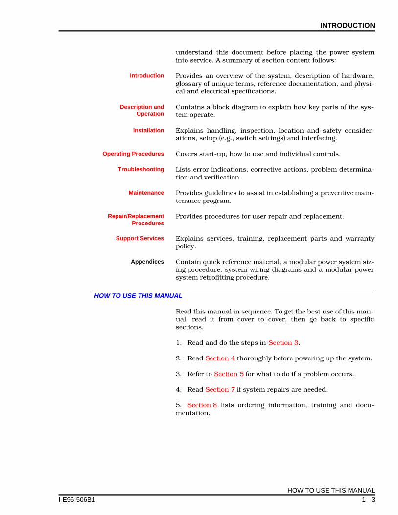
understand this document before placing the power systeminto service. A summary of section content follows:
Introduction Provides an overview of the system, description of hardware,glossary of unique terms, reference documentation, and physi-cal and electrical specifications.
Description andOperation
Contains a block diagram to explain how key parts of the sys-tem operate.
Installation Explains handling, inspection, location and safety consider-ations, setup (e.g., switch settings) and interfacing.
Operating Procedures Covers start-up, how to use and individual controls.
Troubleshooting Lists error indications, corrective actions, problem determina-tion and verification.
Maintenance Provides guidelines to assist in establishing a preventive main-tenance program.
Repair/ReplacementProcedures
Provides procedures for user repair and replacement.
Support Services Explains services, training, replacement parts and warrantypolicy.
Appendices Contain quick reference material, a modular power system siz-ing procedure, system wiring diagrams and a modular powersystem retrofitting procedure.
HOW TO USE THIS MANUAL
Read this manual in sequence. To get the best use of this man-ual, read it from cover to cover, then go back to specificsections.
1. Read and do the steps in Section 3.
2. Read Section 4 thoroughly before powering up the system.
3. Refer to Section 5 for what to do if a problem occurs.
4. Read Section 7 if system repairs are needed.
5. Section 8 lists ordering information, training and docu-mentation.
HOW TO USE THIS MANUAL
1 1 - 3

INTRODUCTION ®
REFERENCE DOCUMENTS
Table 1-1 lists reference documents.
NOMENCLATURE
Table 1-2 lists nomenclatures associated with the IEPAS02and IEPAF02 Power Supply Modules. Refer to Table 7-1 forpart numbers of related items such as cables and fuses.
GLOSSARY OF TERMS AND ABBREVIATIONS
Table 1-3 is a glossary of terms and abbreviations used in thismanual.
Table 1-1. Reference Documents
Document Number
Title
I-E96-500 Site Planning and Preparation
Table 1-2. Nomenclature
Nomenclature Description
IEFAN01 Fan assembly - 120 VAC
IEFAN02 Fan assembly - 240 VAC
IEFAS01 INFI 90 fastener kit
IEMMU01 Module mounting unit (rear mount)
IEMMU02 Module mounting unit (front mount)
IEPAF02 AC field power module
IEPAS02 AC system power module
IEPEP01 Power entry panel with single AC feed and no circuit breaker
IEPEP02 Power entry panel with single AC feed and circuit breaker
IEPEP03 Power entry panel with redundant AC feed and circuit breakers
IEPMU01 Power mounting unit (rear mount)
IEPMU02 Power mounting unit (front mount)
Table 1-3. Glossary of Terms and Abbreviations
Term Definition
ATM AC transfer module.
BMM Bus monitor module.
Controlway High speed, redundant, peer-to-peer communication link. Used to transfer information between intelligent modules within a process control unit.
REFERENCE DOCUMENTS
1 - 4 I-E96-506B1
INTRODUCTION
I-E96-506B
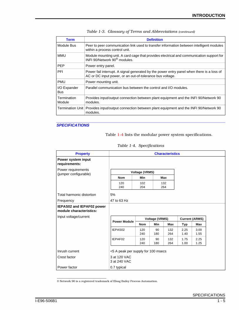
SPECIFICATIONS
Table 1-4 lists the modular power system specifications.
Module Bus Peer to peer communication link used to transfer information between intelligent modules within a process control unit.
MMU Module mounting unit. A card cage that provides electrical and communication support for INFI 90/Network 90® modules.
PEP Power entry panel.
PFI Power fail interrupt. A signal generated by the power entry panel when there is a loss of AC or DC input power, or an out-of-tolerance bus voltage.
PMU Power mounting unit.
I/O Expander Bus
Parallel communication bus between the control and I/O modules.
Termination Module
Provides input/output connection between plant equipment and the INFI 90/Network 90 modules.
Termination Unit Provides input/output connection between plant equipment and the INFI 90/Network 90 modules.
Table 1-3. Glossary of Terms and Abbreviations (continued)
Term Definition
® Network 90 is a registered trademark of Elsag Bailey Process Automation.
Table 1-4. Specifications
Property Characteristics
Power system input requirements:
Power requirements(jumper configurable)
Total harmonic distortion 5%
Frequency 47 to 63 Hz
IEPAS02 and IEPAF02 power module characteristics:
Input voltage/current
Inrush current <5 A peak per supply for 100 msecs
Crest factor 3 at 120 VAC3 at 240 VAC
Power factor 0.7 typical
Voltage (VRMS)
Nom Min Max
120240
102204
132264
Power ModuleVoltage (VRMS) Current (ARMS)
Nom Min Max Typ Max
IEPAS02 120240
90180
132264
2.251.40
3.001.55
IEPAF02 120240
90180
132264
1.751.00
2.251.25
SPECIFICATIONS
1 1 - 5
INTRODUCTION ®
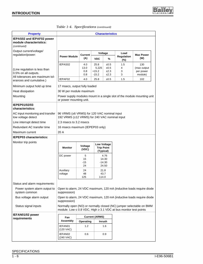
IEPAS02 and IEPAF02 power module characteristics:(continued)
Output current/voltage/ regulation/power:
(Line regulation is less than 0.5% on all outputs.All tolerances are maximum tol-erances and cumulative.)
Minimum output hold up time 17 msecs, output fully loaded
Heat dissipation 30 W per module maximum
Mounting Power supply modules mount in a single slot of the module mounting unit or power mounting unit.
IEPEP01/02/03 characteristics:
AC input monitoring and transfer low voltage detect
96 VRMS (±6 VRMS) for 120 VAC nominal input192 VRMS (±12 VRMS) for 240 VAC nominal input
Line interrupt detect time 2.3 msecs to 3.2 msecs
Redundant AC transfer time 16 msecs maximum (IEPEP03 only)
Maximum current 20 A
IEPEP03 characteristics:
Monitor trip points
Status and alarm requirements:
Power system alarm output to system common
Open to alarm, 24 VDC maximum, 120 mA (inductive loads require diode suppression)
Bus voltage alarm output Open to alarm, 24 VDC maximum, 120 mA (inductive loads require diode suppression)
Status signal inputs Normally open (NO) or normally closed (NC) jumper selectable on BMM module. Low ≤ 0.8 VDC, High ≥ 3.1 VDC at bus monitor test points
IEFAN01/02 power requirements
Table 1-4. Specifications (continued)
Property Characteristics
Power ModuleCurrent
(A)
Voltage LoadRegulation
(%)
Max Power (W)VDC %
IEPAS02 4.013.0
0.80.8
25.85.225
+15.2-15.2
±0.5±0.5±2.3±2.3
1.5433
130(max output per power module)
IEPAF02 4.0 25.8 ±0.5 1.5 102
MonitorVoltage (VDC)
Low VoltageTrip Point(Typical)
DC power 515
-1524
4.7614.30
-14.3024.50
Auxiliary voltage
2448
125
21.843.7
114.0
FanAssembly
Current (ARMS)
Operating Inrush
IEFAN01(120 VAC)
1.2 1.6
IEFAN02(240 VAC)
0.6 0.9
SPECIFICATIONS
1 - 6 I-E96-506B1

INTRODUCTION
I-E96-506B
General system specifications:
Module voltage requirements(at bus monitor test points)
Electromagnetic/radio frequency interference
Values not available at this time. Keep cabinet doors closed. Do not use communication equipment any closer than 2 meters from the cabinet.
Physical dimensions
Environmental:
Room ambient temperature 0° to 55°C (32° to 131°F)
Maximum module ambient tem-perature
70°C (158°F)
Humidity 5% to 90%, up to 55°C (131°F) noncondensing0% to 45% at 70°C (158°F) noncondensing
Cooling (fan) 180 cfm typical
Atmospheric pressure Sea level to 3 km (1.86 mi)
Air quality Noncorrosive
Certification Meets IEEE-472-1974 surge test requirements.
CSA certification as process control equipment in an ordinary (nonhazardous) environment.
SPECIFICATIONS SUBJECT TO CHANGE WITHOUT NOTICE
Table 1-4. Specifications (continued)
Property Characteristics
Module Voltage (VDC) Max Ripple(mV, p to p)Nom Min Max
5+15-1524
4.75+14.30-14.3025.50
5.25+15.75-15.7527.00
50100100100
ComponentHeight Width Depth
mm in. mm in. mm in.
IEPEP01/02 132 5.2 428.6 19 114.3 4.5
IEPEP03 175.2 6.9 428.6 19 685.8 27
IEFAN01/02 44.4 1.75 428.6 19 33.0 13
IEPMU01/02 177.8 7.0 428.6 19 317.5 12.5
IEMMU01/02 177.8 7.0 428.6 19 317.5 12.5
SPECIFICATIONS
1 1 - 7

SECTION 2 - DESCRIPTION AND OPERATION
I-E96-506B
INTRODUCTION
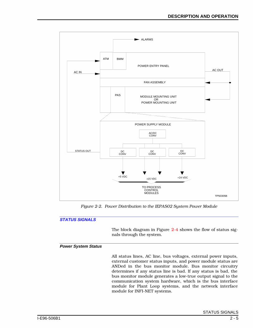
This section uses block diagrams and supportive text toexplain how the main functional blocks of the power systemoperate. The first diagram, Figure 2-1, shows overall systemarchitecture. Figure 2-2 shows power distribution to theIEPAS02 module. Figures 2-3 and 2-4 show circuit details forthe system power module, and AC transfer and bus monitormodule.
Figure 2-1. Modular Power System Architecture
POWER ENTRY PANEL
120/240 VAC
120/240 VAC
ALARM CONTACTOUTPUT
INPUTPOWERBUS BAR
LINE 1 LINE 2
MODULE MOUNTING UNIT
EXTERNAL SUPPLY ANDCUSTOMER STATUS
BUS MONITORDETECTION POINTSAND ALARM
SYSTEMPOWER
BUS BAR
+15 VDC–15 VDC+24 VDC
+5 VDC
MODULE ALARM
ANY INFI 90 MODULES
MODULE MOUNTING UNIT
+15 VDC
–15 VDC
+5 VDC
ANY INFI 90 MODULES
TP40011B
FAN
PAFORPAS
+15 VDC
–15 VDC+24 VDC
+5 VDC
MODULE ALARM
MODULE MOUNTING UNIT
+24 VDC FOR I/O
+24 VDC COMMON
ANY INFI 90 MODULESPAFORPAS
PAFORPAS
PAFORPAS
INTRODUCTION
1 2 - 1
DESCRIPTION AND OPERATION ®
POWER DISTRIBUTION
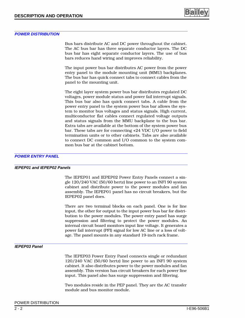
Bus bars distribute AC and DC power throughout the cabinet.The AC bus bar has three separate conductor layers. The DCbus bar has eight separate conductor layers. The use of busbars reduces hand wiring and improves reliability.
The input power bus bar distributes AC power from the powerentry panel to the module mounting unit (MMU) backplanes.The bus bar has quick connect tabs to connect cables from thepanel to the mounting unit.
The eight layer system power bus bar distributes regulated DCvoltages, power module status and power fail interrupt signals.This bus bar also has quick connect tabs. A cable from thepower entry panel to the system power bus bar allows the sys-tem to monitor bus voltages and status signals. High current,multiconductor flat cables connect regulated voltage outputsand status signals from the MMU backplane to the bus bar.Extra tabs are available at the bottom of the system power busbar. These tabs are for connecting +24 VDC I/O power to fieldtermination units or to other cabinets. Tabs are also availableto connect DC common and I/O common to the system com-mon bus bar at the cabinet bottom.
POWER ENTRY PANEL
IEPEP01 and IEPEP02 Panels
The IEPEP01 and IEPEP02 Power Entry Panels connect a sin-gle 120/240 VAC (50/60 hertz) line power to an INFI 90 systemcabinet and distribute power to the power modules and fanassembly. The IEPEP01 panel has no circuit breakers, but theIEPEP02 panel does.
There are two terminal blocks on each panel. One is for lineinput, the other for output to the input power bus bar for distri-bution to the power modules. The power entry panel has surgesuppression and filtering to protect the power modules. Aninternal circuit board monitors input line voltage. It generates apower fail interrupt (PFI) signal for low AC line or a loss of volt-age. The panel mounts in any standard 19-inch rack frame.
IEPEP03 Panel
The IEPEP03 Power Entry Panel connects single or redundant120/240 VAC (50/60 hertz) line power to an INFI 90 systemcabinet. It also distributes power to the power modules and fanassembly. This version has circuit breakers for each power lineinput. This panel also has surge suppression and filtering.
Two modules reside in the PEP panel. They are the AC transfermodule and bus monitor module.
POWER DISTRIBUTION
2 - 2 I-E96-506B1

DESCRIPTION AND OPERATION
I-E96-506B
AC Transfer Module
The AC transfer module (ATM) monitors both the AC inputsand its own circuitry. If an AC input is lost or faulty, the mod-ule automatically transfers to the redundant input. The ATMmodule generates a power fail interrupt signal if both lines arelost or below the low voltage threshold. It sends this signal tothe bus monitor module (BMM). The BMM module sends thePFI signal to the appropriate process control modules, therebyinterrupting their operation.
Visible through the front panel are three LED indicators. Thered/green LED at the top shows whether the module is operat-ing normally (green) or not (red). The two other LEDs (LINE 1and LINE 2) provide AC input status (green = good, red = bad).
Bus Monitor Module
The bus monitor module (BMM) monitors the regulated busvoltages (+5, +15, -15 and +24 VDC) and module status fromthe distribution bus bar. A cable connection between the busbar and the J2 connector on the PEP panel provides the path.The BMM module can also monitor two additional externalpower supply voltages at the PEP terminal blocks. User config-ured jumpers allow the module to monitor either 24, 48 or125 VDC for up to two auxiliary power supplies.
There are two contact inputs (NO or NC) for monitoring systemstatus signals. Two red/green LEDs on the module faceplateprovide status information. The top-most LED shows whetherthe module is operating properly (green) or not (red). The sys-tem status LED is red when voltages are low or other inputsare bad. The status signal goes to the communication systemhardware, which is the bus interface module for Plant Loopsystems, and the network interface module for INFI-NET ® sys-tems. Once on the communication loop, any INFI 90 operatorinterface can use the signal.
There are two alarms: PWR SYS ALARM and BUS VOLTALARM. The PWR SYS ALARM becomes active when a powersystem problem occurs. The BUS VOLT ALARM becomes activewhen any bus voltage (+5, +15, -15 or +24 VDC) falls out of tol-erance. The BMM module also generates a power fail interrupt(PFI) signal if it receives a PFI from the AC transfer module, or ifthe +5 VDC bus voltage is low. It distributes this signal to pro-cess control modules in the INFI 90 system cabinet.
NOTE: The bus monitor module receives power from the AC trans-fer module. Therefore, the AC transfer module must be in place andoperating properly before the bus monitor module will work.
® INFI-NET is a registered trademark of Elsag Bailey Process Automation.
POWER ENTRY PANEL
1 2 - 3
DESCRIPTION AND OPERATION ®
FAN ASSEMBLY
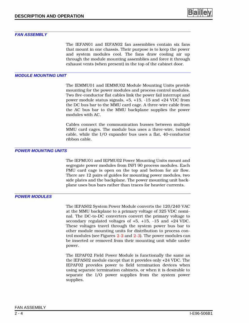
The IEFAN01 and IEFAN02 fan assemblies contain six fansthat mount in one chassis. Their purpose is to keep the powerand system modules cool. The fans draw cooling air upthrough the module mounting assemblies and force it throughexhaust vents (when present) in the top of the cabinet door.
MODULE MOUNTING UNIT
The IEMMU01 and IEMMU02 Module Mounting Units providemounting for the power modules and process control modules.Two five-conductor flat cables link the power fail interrupt andpower module status signals, +5, +15, -15 and +24 VDC fromthe DC bus bar to the MMU card cage. A three-wire cable fromthe AC bus bar to the MMU backplane supplies the powermodules with AC.
Cables connect the communication busses between multipleMMU card cages. The module bus uses a three-wire, twistedcable, while the I/O expander bus uses a flat, 40-conductorribbon cable.
POWER MOUNTING UNITS
The IEPMU01 and IEPMU02 Power Mounting Units mount andsegregate power modules from INFI 90 process modules. EachPMU card cage is open on the top and bottom for air flow.There are 12 pairs of guides for mounting power modules, twoside plates and the backplane. The power mounting unit back-plane uses bus bars rather than traces for heavier currents.
POWER MODULES
The IEPAS02 System Power Module converts the 120/240 VACat the MMU backplane to a primary voltage of 325 VDC nomi-nal. The DC-to-DC converters convert the primary voltage tosecondary regulated voltages of +5, +15, -15 and +24 VDC.These voltages travel through the system power bus bar toother module mounting units for distribution to process con-trol modules (see Figures 2-2 and 2-3). The power modules canbe inserted or removed from their mounting unit while underpower.
The IEPAF02 Field Power Module is functionally the same asthe IEPAS02 module except that it provides only +24 VDC. TheIEPAF02 provides power to field termination devices whenusing separate termination cabinets, or when it is desirable toseparate the I/O power supplies from the system powersupplies.
FAN ASSEMBLY
2 - 4 I-E96-506B1
DESCRIPTION AND OPERATION
I-E96-506B
STATUS SIGNALS
The block diagram in Figure 2-4 shows the flow of status sig-nals through the system.
Power System Status
All status lines, AC line, bus voltages, external power inputs,external customer status inputs, and power module status areANDed in the bus monitor module. Bus monitor circuitrydetermines if any status line is bad. If any status is bad, thebus monitor module generates a low-true output signal to thecommunication system hardware, which is the bus interfacemodule for Plant Loop systems, and the network interfacemodule for INFI-NET systems.
Figure 2-2. Power Distribution to the IEPAS02 System Power Module
BMM
POWER ENTRY PANEL
MODULE MOUNTING UNITOR
POWER MOUNTING UNIT
POWER SUPPLY MODULE
DCCONV
DCCONV
DCCONV
±15 VDC
ALARMS
TP50305B
+24 VDC+5 VDC
AC OUTAC IN
AC/DCCONV
TO PROCESSCONTROLMODULES
STATUS OUT
PAS
FAN ASSEMBLY
ATM
STATUS SIGNALS
1 2 - 5
DESCRIPTION AND OPERATION ®
WER 24 V
MMON
MON
MON
S
TP50311B
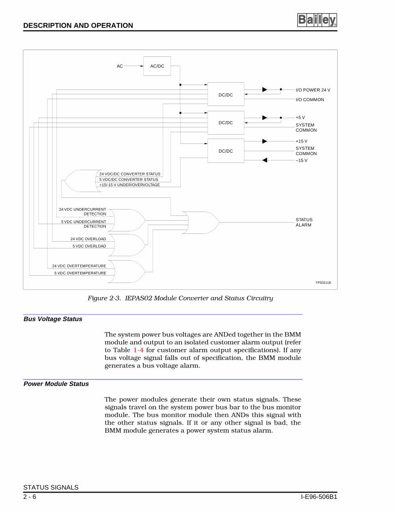
Bus Voltage Status
The system power bus voltages are ANDed together in the BMMmodule and output to an isolated customer alarm output (referto Table 1-4 for customer alarm output specifications). If anybus voltage signal falls out of specification, the BMM modulegenerates a bus voltage alarm.
Power Module Status
The power modules generate their own status signals. Thesesignals travel on the system power bus bar to the bus monitormodule. The bus monitor module then ANDs this signal withthe other status signals. If it or any other signal is bad, theBMM module generates a power system status alarm.
Figure 2-3. IEPAS02 Module Converter and Status Circuitry
24 VDC/DC CONVERTER STATUS
AC AC/DC
DC/DCI/O PO
I/O CO
SYSTECOMM
SYSTECOMM
STATUALARM
+5 V
+15 V
–15 V
DC/DC
DC/DC
24 VDC OVERTEMPERATURE
5 VDC UNDERCURRENTDETECTION
24 VDC UNDERCURRENTDETECTION
+15/-15 V UNDER/OVERVOLTAGE5 VDC/DC CONVERTER STATUS
24 VDC OVERLOAD
5 VDC OVERLOAD
5 VDC OVERTEMPERATURE
STATUS SIGNALS
2 - 6 I-E96-506B1

DESCRIPTION AND OPERATION
I-E96-506B
Customer Alarm Outputs
There are two customer alarm outputs (normally closed): busvoltage and power system status alarm. The bus voltage alarmactivates (opens) if any bus voltage goes low or is lost. Thepower system status alarm activates (opens) for any bad sta-tus. These outputs are optically isolated and can drive relaysor annunciator panels.
Figure 2-4. Status Signal Block Diagram
AC LINE 1AC LINE 2
MODULE STATUS
PFI+5 V+15 V–15 V+24 VPM STAT
DC BUS
STATUS
PFIATMIEPEP03
BMM
AUX BUS MONITOR 1AUX BUS MONITOR 2
STATUS IN 1STATUS IN 2
MODULE STATUS (BMM)MODULE STATUS (ATM)
PM STAT
IEPAS02IEPAF02 IEMMU01/02
LIM BIM
POWERSYSTEMSTATUS
NIS
PFI
TU TU
TP50304B
PLANT LOOPMCS, OIS,ETC.
INFI-NET
BUSVOLT
ALARM
POWERSYS
ALARM
+
+
–
–
STATUS SIGNALS
1 2 - 7
SECTION 3 - INSTALLATION
I-E96-506B
INTRODUCTION
Completely install and prepare the hardware before applyingpower (i.e., attach wiring to terminal blocks, etc.). This sectionexplains hardware preparation in detail.
NOTE: Normally, the cabinet is fully wired and ready to go uponreceipt. The following information is provided in the event that youneed to repair, replace, rewire or add to the modular power system.
UNPACKING AND INSPECTION
The power modules are in separate packages from the rest ofthe power system. Follow the guidelines in Special Handlingwhen handling these modules.
Special Handling
Observe these steps when handling electronic circuitry:
NOTE: Always use Bailey's field static kit (part number 1948385A1 -consisting of two wrist straps, ground cord assembly, alligator clipand static dissipative work surface) when working with the modules.The kit grounds a technician and the static dissipative work surfaceto the same ground point to prevent damage to the modules by elec-trostatic discharge.
1. Use Static Shielding Bag. Keep the modules in the staticshielding bag until you are ready to install them in the system.Save the bag for future use.
2. Ground Bag Before Opening. Before opening a bag con-taining an assembly with semiconductors, touch it to theequipment housing or a ground to equalize charges.
3. Avoid Touching Circuitry. Handle assemblies by theedges; avoid touching the circuitry.
4. Avoid Partial Connection of Semiconductor. Verify thatall devices connected to the modules are properly groundedbefore using them.
5. Ground Test Equipment.
6. Use Antistatic Field Service Vacuum. Remove dust fromthe module if necessary.
7. Use a Grounded Wrist Strap. Connect the wrist strap tothe appropriate grounding plug on the power entry panel. The
INTRODUCTION
1 3 - 1

INSTALLATION ®
grounding plug on the power entry panel must be effectivelyconnected to the earth grounding electrode system through theAC safety ground.
8. Do Not Use Lead Pencils to Set Dipswitches. To avoidcontamination of switch contacts that can result in unneces-sary circuit board malfunction, do not use a lead pencil to set adipswitch.
General Handling
1. Examine the hardware immediately to verify that it has notbeen damaged in transit.
2. Notify the nearest Bailey Controls Company sales office ofany such damage.
3. File a claim for any damage with the transportation com-pany that handled the shipment.
4. Use the original packing material and container to store thehardware.
5. Store the hardware in an environment of good air quality,free from temperature and moisture extremes.
IEPEP03 POWER ENTRY PANEL WIRING
The appendices at the back of this manual show complete wir-ing diagrams of the modular power system. Figures C-1 andC-2 show the IEPEP03 system cabinet wiring diagram.
NOTE: Plug your wrist strap ground cord into the receptacle labeledWRIST STRAP GND when working with the system.
1. Place circuit breakers CB1 and CB2 (see Figure 3-1) on thefront of the panel to the off position before connecting ACpower input wiring.
WARNING
Verify the main power and power entry panel circuit breakersare turned off before starting installation, retrofit, upgrade, orwiring procedures. Failure to do so could result in severe orfatal shock. Do not turn the power on until the installation, ret-rofit, upgrade, or wiring procedures are complete.
AVERTISSEMENT
Assurez-vous que le disjoncteur d'alimentation principal et ledisjoncteur de panneau d'entrée des alimentations sont éteintsavant de procéder à l'installation, à la mise à jour, à l'extensionou au câblage, dans le but d'éviter les chocs sérieux et mêmemortels. Ne rétablissez pas l'alimentation tant que ces procé-dures ne sont pas terminées.
IEPEP03 POWER ENTRY PANEL WIRING
3 - 2 I-E96-506B1

INSTALLATION
I-E96-506B
2. Connect the primary 120 VAC or 240 VAC power lines toTB1-1, TB1-2 and TB1-3.
3. Connect the secondary AC power lines (if used) to TB1-4,TB1-5 and TB1-6. Both inputs must be the same nominal volt-age level.
If only one AC power input is being used, proceed with Step 4.If not, skip to Step 5.
4. Connect TB1-1 to TB1-4, TB1-2 to TB1-5, and TB1-3 toTB1-6. Use 12 AWG as a minimum and 6 AWG as a maximum.Note that this step avoids false bad status information becauseit connects line 1 and line 2 inputs together.
5. Connect cable 6637813_1 from J2 on the power entrypanel to the system power bus bar. This cable provides connec-tions to sample the DC bus voltages, monitor the powermodule status signal and output a power fail interrupt signal.
Figure 3-1. Circuit Breakers CB1/CB2
IEPEP03
WRISTSTRAP
GROUNDCB2 CB1LINE 2 LINE 1
IEFAN0�
IEPAS0�
IEPAS0�IEPAS0�
IEPAS0�
TP25377B
IEPEP03 POWER ENTRY PANEL WIRING
1 3 - 3

INSTALLATION ®
See the wiring diagrams at the end of this manual (seeFigure C-1) for the correct system power bus bar connections.
6. Connect cable 6637814_2 from TB2-4, TB2-5 and TB2-6on the power entry panel to the input power bus bar for distri-bution of AC power to the module mounting unit.
7. Connect cable 6637818_2 from the input power bus bar toeach module mounting unit backplane (see Figure C-1).
8. Connect the fan assembly power cable to connector J1labeled FAN OUT on the panel.
9. Connect a wire equivalent to power wiring but not less than10 AWG from the GND stud of the panel to the cabinet framefor AC safety grounding.
10. There are 2 extra voltage monitor inputs available to moni-tor external power supply voltages. Use terminal block TB4labeled AUX BUS MONITOR for this purpose. Attach 1 input toterminals 1 (+) and 2 (-) labeled CH1. Connect the other inputto terminals 3 (+) and 4 (-) labeled CH2. Inputs can be +24, +48or +125 VDC. Refer to Bus Monitor Module in this section fordipswitch and jumper settings to enable these inputs andselect the input voltage.
11. Wire the auxiliary status inputs to terminal block TB3-1(STATUS IN 1), TB3-2 (COM), and TB3-3 (STATUS IN 2). Insurethat the inputs are low true, open collector or contact type ref-erenced to DC common (terminal COM) and reflect the jumpersettings of the bus monitor module (NO or NC). The alarminputs must have the current carrying capability to sink atleast 1 mA.
If the system uses the Plant Loop communication network con-tinue to Step 12. If the system uses the INFI-NET communica-tion network go to Step 13.
12. Connect cable 6634205_1 from TB3-4 (STATUS OUT) to theP3 card edge connector of the bus interface module (BIM).Doing so enables the BIM module to send the status messageto the loop interface module (LIM) and to other nodes on thePlant Loop communication system.
Go to Step 16.
13. Connect an 18 AWG wire from TB3-4 (STATUS OUT) on thepower entry panel to TB1-8 on the NTCL01 termination unit.
14. If 2 NTCL01 termination units connect to redundant net-work interface I/O modules:
a. Put two 18 AWG wires on a lug. Attach the lug to TB3-4(STATUS OUT) on the power entry panel.
IEPEP03 POWER ENTRY PANEL WIRING
3 - 4 I-E96-506B1
INSTALLATION
I-E96-506B
b. Attach the one wire to TB1-8 on the primary NTCL01termination unit; the second wire attaches to TB1-8 on thesecondary termination unit.
15. If redundant network interface I/O modules are being usedwith the NICL01 termination module:
a. Put two 18 AWG wires on a lug. Attach the lug to TB3-4(STATUS OUT) on the power entry panel.
b. Attach the primary wire to TB2-4 on the primaryNICL01 termination module; the second wire attaches toTB2-4 on the secondary termination module.
16. Use TB3-5, TB3-6, TB3-7 and TB3-8 for connecting thealarms. Use 18 AWG wire. Terminals 5 (+) and 6 (-) are labeledPWR SYS. These are the output connections for the power sys-tem alarm. Terminals 7 (+) and 8 (-) labeled BUS VOLT are thebus voltage alarm annunciators.
NOTE: Wire your system per the color codes of the wiring diagramsin Appendix C.
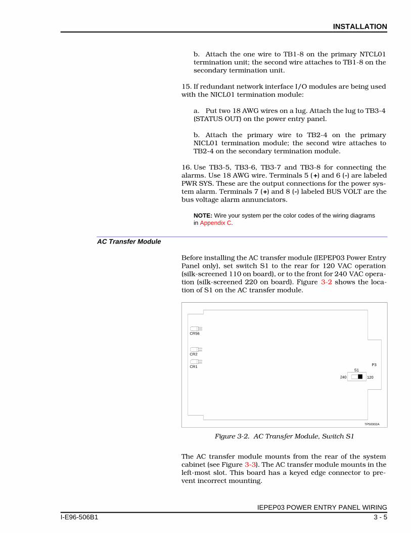
AC Transfer Module
Before installing the AC transfer module (IEPEP03 Power EntryPanel only), set switch S1 to the rear for 120 VAC operation(silk-screened 110 on board), or to the front for 240 VAC opera-tion (silk-screened 220 on board). Figure 3-2 shows the loca-tion of S1 on the AC transfer module.
The AC transfer module mounts from the rear of the systemcabinet (see Figure 3-3). The AC transfer module mounts in theleft-most slot. This board has a keyed edge connector to pre-vent incorrect mounting.
Figure 3-2. AC Transfer Module, Switch S1
S1P3
TP50302A
CR56
CR2
CR1
240 120
IEPEP03 POWER ENTRY PANEL WIRING
1 3 - 5

INSTALLATION ®
P25378B
RAR
R ENTRY
03
INPUT0/60 HZ
To mount the module:
NOTE: Be careful not to bump switch S1 when installing the ACtransfer module. Accidentally moving the switch to the 240 positionwill cause the module to go into error mode.
1. Grasp the sides of the faceplate.
2. Line up circuit board edges with card guides in the powerentry panel opening.
3. Slide the module in until it locks in place.
Figure 3-3. IEPEP03 Power Entry Panel, Rear View
1 2 6543
T
INPUTPOWEBUS B
SYSTEMPOWER
BUS BAR
FANASSEMBLY
ATMSLOT
BMMSLOT
J2TB4
TB2J1
120 VAC240 VAC
120 VAC240 VAC
TB1 1 2 65431
1 5
2
2 6
CH1+ –
PWRSYS+ –
BUSVOLT+ –
CH2+ –
AUX BUSMONITOR
STATUS
IN1 COM 2 OUT
ALARMS
GNDFANOUT
AC OUT
LL1
LL1
LL1
NL2
NL2
NL2
3
3 7
4
4 8TB3POWEPANELIEPEPROW 0
AUX. POWER120/240 VAC 5
MAIN POWER INPUT120/240 VAC 50/60 HZ
L (L1)
N (L2)N (L2)
L (L1)
IEPEP03 POWER ENTRY PANEL WIRING
3 - 6 I-E96-506B1

INSTALLATION
I-E96-506B
4. Turn the 2 locking screws on the AC transfer module face-plate 1/2-turn to lock the module in place.
Bus Monitor Module
Before mounting the bus monitor module (IEPEP03 PowerEntry Panel only), set switch S1 and jumpers J1 through J8.Figure 3-4 shows the switch and jumper locations on the busmonitor module circuit board. Refer to Table 3-1 for the busmonitor module switch settings. Refer to Table 3-2 for the busmonitor module jumper settings.
The bus monitor module mounts from the rear of the systemcabinet (see Figure 3-3). The bus monitor module mounts inthe right-most slot. This board has a keyed edge connector toprevent incorrect mounting.
To mount the module:
1. Grasp the sides of the faceplate.
2. Line up circuit board edges with card guides in the powerentry panel opening.
3. Slide the module in until it locks in place.
4. Turn the 2 locking screws on the bus monitor module face-plate 1/2-turn to lock the module in place.
Figure 3-4. Bus Monitor Module, Switch S1 and Jumpers J1 through J8
S1
J1
P3
TP50301B
CR12
CR17
ON
1 2 3 4
J2
J3
J4
J5
J6
J7
1
2
3
4
1 2 3
4
1 2 3
J8
1 2 3
1
2
3
1
2
3
1
2
3
4
1
2
3
IEPEP03 POWER ENTRY PANEL WIRING
1 3 - 7

INSTALLATION ®
Table 3-1. Bus Monitor Module Switch Settings
Switch S1 PositionFunction 1
1 2 3 4
0 Enable 5, ±15 VDC monitoring
1 Disable 5, ±15 VDC monitoring
0 Enable 24 VDC monitoring
1 Disable 24 VDC monitoring
0 Enable auxiliary bus monitoring CH1
1 Disable auxiliary bus monitoring CH1
0 Enable auxiliary bus monitoring CH2
1 Disable auxiliary bus monitoring CH2NOTES: 0 = CLOSED or ON, 1 = OPEN or OFF1. Do not enable all inputs simultaneously. Doing so will cause a bad status signal. Unused monitorinputs must be disabled. Figure 3-4 shows the factory settings of switch S1.
Table 3-2. Bus Monitor Module Jumper Settings
Jumper Number
JumperPosition
Function 1
J1
1-2
2-4
2-3
Auxiliary bus monitor, channel 1:
Selects 24 VDC external power
Selects 48 VDC external power
Selects 125 VDC external power
J2
1-2
2-4
2-3
Auxiliary bus monitor, channel 2:
Selects 24 VDC external power
Selects 48 VDC external power
Selects 125 VDC external power
J3
1-2
2-3
AC input voltage, line 2:
Selects 120 VAC input
Selects 240 VAC input
J4
1-2
2-3
3-4
Auxiliary status input 1:
Normally open status input
Normally closed status input
Not used
J5
1-2
2-3
Auxiliary status input 2:
Normally open status input
Normally closed status input
J6 1-2 Must be set as shown
J7
1-2
2-3
AC input voltage, line 1:
Selects 120 VAC input
Selects 240 VAC input
J8 2-3 Must be set as shownNOTE:1. Placing a shorting strap over the jumper pins selects the function.
IEPEP03 POWER ENTRY PANEL WIRING
3 - 8 I-E96-506B1
INSTALLATION
I-E96-506B
Fan Assembly
The IEFAN01 or IEFAN02 fan assembly mounts directlybeneath the power entry panel and above the power mountingunit or the first module mounting unit (see Figure C-2). Attachthe fan power cable to the J1 connector on the power entrypanel.
Power Modules
Power modules mount directly in the module mounting unit orpower mounting unit. Use any slot except the right-most slot(slot 12) when mounting a power module in a module mount-ing unit.
Mount the power modules in any slot when using a powermounting unit. Figure 3-5 shows the recommended mountingpattern and spacing when mounting power modules in modulemounting units. This installation scheme provides the bestheat dissipation and power distribution. For optimum heat dis-sipation and power distribution, do not exceed more than twoIEPAS02 modules in any module mounting unit. Install at leastone IEPAS02 module in the module mounting unit with thelargest load (e.g., a module mounting unit containing severalmulti-function processor modules).
NOTE: Power mounting units can hold a maximum of 12 powermodules mounted side by side. However the total five VDC currentload on the power mounting unit cannot exceed 100 amps. The total24 VDC current load on the power mounting unit cannot exceed60 amps.
Before handling the power modules:
1. Verify that all devices connected to the module are properlygrounded before using them.
2. Avoid touching the circuitry when handling the module.
3. Always use grounding straps (field static kits) when work-ing with the modules.
WARNINGDo not remove the plastic covers on the module mounting unitbackplane. These covers protect against accidental contactwith AC voltage. Severe or fatal shock could result.
AVERTISSEMENT
Ne retirez pas les couvercles de plastique situés sur le pan-neau arrière du châssis de montage des modules. Ces couver-cles constituent une protection contre les contacts accidentelsavec la tension c.a., qui risquent de provoquer des chocssérieux et même mortels.
IEPEP03 POWER ENTRY PANEL WIRING
1 3 - 9

INSTALLATION ®
To install the power supply module:
1. Set jumpers J1 through J3 on the IEPAS02 module and setjumpers J1 and J2 on the IEPAF02 module (the IEPAF02 mod-ule does not have J3) for the module operation desired. Table3-3 lists the IEPAS02 and IEPAF02 jumper settings. Figure 3-6shows the jumper locations on the IEPAS02 and IEPAF02power modules. Refer to Table 4-2 for information on the mon-itoring priority levels of the power module jumper settings.
2. Grasp the module faceplate handle and align the top andbottom edges of the circuit board with the guides in the mod-ule mounting unit.
3. Hold the module by the faceplate handle and slide it intothe MMU slot. Push on the faceplate until the rear edge con-nectors of the power module are firmly seated in the backplaneconnectors.
4. Firmly press the module handle as you use a blade screw-driver to push and turn the 2 concentric screws 1/2-turnclockwise to lock the module in place.
Figure 3-5. Recommended Power Module Layout for Module Mounting Unit
TP50300A
PAS PAS
1 2 3 4 5 6 7 8 9 10 11 12
PASPAS
PAS PAS
PASPAS
NOTUSED
NOTUSED
NOTUSED
NOTUSED
IEPEP03 POWER ENTRY PANEL WIRING
3 - 10 I-E96-506B1

INSTALLATION
I-E96-506B
Figure 3-6. IEPAF02 and IEPAS02 Power Module Board Layout
IEPAS02
IEPAF02
J21 2 3
J21 2 3
J31 2 3
J1F1
F1
123
J1123
TP50307B
Table 3-3. IEPAS02 and IEPAF02 Power Module Jumper Settings
Jumper Number
JumperPosition
Function
J1 1-2 120 VAC
2-3 240 VAC
J2 1-2 Enable 24 VDC undercurrent monitoring
2-3 Disable 24 VDC undercurrent monitoring
J31 1-2 Enable 5 VDC undercurrent monitoring
2-3 Disable 5 VDC undercurrent monitoringNOTE:1. The IEPAF02 does not have jumper J3.
WARNINGAllow five seconds for the line filter capacitors to dischargebefore handling the module after removal. Failure to do socould result in severe or fatal shock.
IEPEP03 POWER ENTRY PANEL WIRING
1 3 - 11
INSTALLATION ®
To remove the module:
1. Use a blade screwdriver to push and turn the 2 concentricscrews 1/2-turn in either direction.
2. Slide the module part way out.
3. Allow 5 seconds for the module capacitors to discharge.Then remove the module from its mounting unit.
IEPEP01 AND IEPEP02 POWER ENTRY PANEL WIRING
NOTE: The IEPEP01 Power Entry Panel requires you to supply anexternal circuit breaker or fuse. The breaker or fuse must be able tohandle the current and voltage listed in the specifications table(Table 1-4).
1. Set the slide switch on the rear of the power entry panel toeither 120 V or 240 V to match the line voltage. This switchsets the power fail interrupt (PFI) detection circuit to determinelow level or loss of input. Figure 3-7 shows this switch on therear of the IEPEP01 and IEPEP02 power entry panels.
2. Connect cable 6638084_1 from the PFI connector on therear of the panel to the system power bus bar. This connectiondistributes a power fail interrupt to the process control mod-ules in the cabinet.
AVERTISSEMENT
Après avoir retiré le module, laissez les condensateurs de fil-tres antiparasites se décharger pendant cinq secondes avantde manipuler celui-ci, afin d'éviter les chocs sérieux et mêmemortels.
WARNINGHandle the module by surfaces other than the heat sink. Theheat sink may be hot and may cause severe burns.
AVERTISSEMENTLe module doit être manipulé à l'aide de surfaces autres que ledissipatour thermique. Ce dernier resque d'être chaud et deprovoquer des brûlures sérieuses.
CAUTION
Verify the line voltage select switch is properly configuredbefore energizing the power entry panel. Failure to do so couldpermanently damage the PFI circuit board by exposing it toimproper input voltage levels.
ATTENTION
Assurez-vous que l'interrupteur de sélection de la tension deligne est adéquatement configuré avant de mettre sous tensionle panneau d'entrée des alimentations. Toute négligence à cetégard risque d'endommager de facon permanente la carte dedétection des coupures d'alimentation (PFI) en l'exposant àdes niveaux inadéquats de tension d'entrée.
IEPEP01 AND IEPEP02 POWER ENTRY PANEL WIRING
3 - 12 I-E96-506B1

INSTALLATION
I-E96-506B
PFI
Figure C-3 shows a wiring diagram of the IEPEP01 andIEPEP02 Power Entry Panels with module mounting units. Fig-ure C-4 shows the IEPEP01 and IEPEP02 Power Entry Panelswith a power mounting unit.
3. Connect cable 6637814_1 from TB2 on the rear of thepower entry panel panel to the input power bus bar. This con-nection places AC power on the input power bus bar.
4. Plug the fan assembly power cable into the FAN OUT con-nector on the rear of the panel.
5. Connect a yellow/green wire equivalent to the power wiringsize (not less than 10 AWG) from the GND bolt on the panel tothe cabinet frame for AC safety grounding (see Figure C-3).
6. Apply power by connecting the 120/240 VAC, 50/60 hertzpower input to terminal block TB1 on the rear of the panel.
NOTE: Wire your system using the color codes in the wiring diagramof Figure C-3 or C-4.
IEPMU01 AND IEPMU02 POWER MOUNTING UNIT INSTALLATION
Figure 3-7. Rear of IEPEP01 and IEPEP02 Power Entry Panels
AC OUT
TB2
120 VAC
240 VAC
L
L1
N
L2
TP25389A
240 VAC
GND FAN OUT
AC IN
TB1
120 VAC
240 VAC
WARNING/AVERTISSEMENT 120/240 V
L
L1
N
L2
WRISTGROUND
STRAP
120 VAC
WARNING
Verify the main power and power entry panel circuit breakersare turned off before starting installation, retrofit, upgrade, orwiring procedures. Failure to do so could result in severe orfatal shock. Do not turn the power on until the installation, ret-rofit, upgrade, or wiring procedures are complete.
AVERTISSEMENT
Assurez-vous que le disjoncteur d'alimentation principal et ledisjoncteur de panneau d'entrée des alimentations sont éteintsavant de procéder, à la mise jour, à l'extension ou au câblage,dans le but d'éviter les chocs sérieux et même mortels. Nerétablissez pas l'alimentation tant que ces procédures ne sontpas terminées.
IEPMU01 AND IEPMU02 POWER MOUNTING UNIT INSTALLATION
1 3 - 13
INSTALLATION ®
Required Tools
The following tools are needed to install the power mountingunit:
• 16-inch blade screwdriver.• 7/16-inch nut driver.• Pliers.• Volt/ohmmeter.• Heat gun.
Installation in the INFI 90 Cabinet
NOTE: Install the IEPMU01 unit from the rear of the cabinet, theIEPMU02 unit from the front.
1. Mount the power mounting unit directly beneath the fanassembly.
2. Secure both sides of the power mounting unit to the cabi-net mounting rails.
3. Proceed to Wiring Instructions.
Wiring Instructions
NOTE: Do all wiring at the rear of the cabinet. Wires arecolor-coded.
Steps 1 through 23 and Figures C-2 and C-4 apply to INFI 90cabinets only. Refer to Appendix D for instructions on retrofit-ting the power mounting unit in Network 90 cabinets.
1. Attach the AC input wire harness (part number6637814_2) to TB2 on the power entry panel (PEP). Attach theother end of the wire harness to the terminal block on the rightside of the power mounting unit. Wire and terminal assign-ments on the PMU terminals are:
Green/Yellow - to ground tab (top)Blue - to L2 Neutral (middle)Brown - to L1 Hot (bottom)
2. On the left side of the PMU card cage starting at the thirdconductive strip (from the top), attach one end of the firstheavy 0 AWG wire assembly (part number 6632285_45).
NOTE: For Steps 2 and 5, before installing the 0 AWG (part number6632285_45) braided wire, shape it into a [ form to avoid overstress-ing the PMU bus bar terminals.
3. Attach the other end to the system MCOM tab at the top ofthe system power bus bar.
IEPMU01 AND IEPMU02 POWER MOUNTING UNIT INSTALLATION
3 - 14 I-E96-506B1
INSTALLATION
I-E96-506B
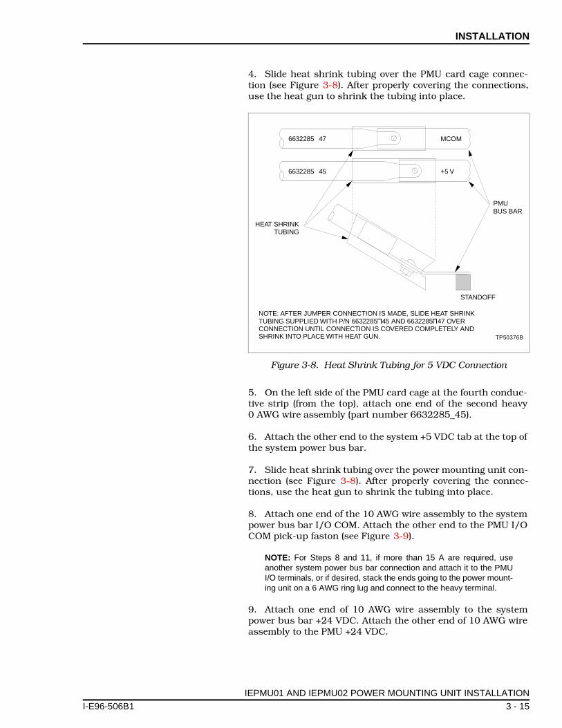
4. Slide heat shrink tubing over the PMU card cage connec-tion (see Figure 3-8). After properly covering the connections,use the heat gun to shrink the tubing into place.
5. On the left side of the PMU card cage at the fourth conduc-tive strip (from the top), attach one end of the second heavy0 AWG wire assembly (part number 6632285_45).
6. Attach the other end to the system +5 VDC tab at the top ofthe system power bus bar.
7. Slide heat shrink tubing over the power mounting unit con-nection (see Figure 3-8). After properly covering the connec-tions, use the heat gun to shrink the tubing into place.
8. Attach one end of the 10 AWG wire assembly to the systempower bus bar I/O COM. Attach the other end to the PMU I/OCOM pick-up faston (see Figure 3-9).
NOTE: For Steps 8 and 11, if more than 15 A are required, useanother system power bus bar connection and attach it to the PMUI/O terminals, or if desired, stack the ends going to the power mount-ing unit on a 6 AWG ring lug and connect to the heavy terminal.
9. Attach one end of 10 AWG wire assembly to the systempower bus bar +24 VDC. Attach the other end of 10 AWG wireassembly to the PMU +24 VDC.
Figure 3-8. Heat Shrink Tubing for 5 VDC Connection
6632285 47� MCOM
6632285 45�
HEAT SHRINKTUBING
PMUBUS BAR
STANDOFF
+5 V
NOTE: AFTER JUMPER CONNECTION IS MADE, SLIDE HEAT SHRINKTUBING SUPPLIED WITH P/N 6632285 45 AND 6632285 47 OVERCONNECTION UNTIL CONNECTION IS COVERED COMPLETELY ANDSHRINK INTO PLACE WITH HEAT GUN.
� �
TP50376B
IEPMU01 AND IEPMU02 POWER MOUNTING UNIT INSTALLATION
1 3 - 15

INSTALLATION ®
10. Attach one spade lug end of 10 AWG wire assembly to thePMU +15 VDC. Attach the other spade lug end to system powerbus bar +15 VDC.
11. Attach one spade lug end of a 10 AWG wire assembly toPMU -15 VDC. Attach the other spade lug end to system powerbus bar -15 VDC.
12. Attach the spade lug end of cable 6637813_1 (IEPEP03panel only) to STATUS on the PMU card cage (see Figure C-2).
13. Make the other signal connections from J2 to the systempower bus bar using cable 6637813_1.
14. Use an ohmmeter to verify continuity between TB2 on theIEPEP03 and the AC terminals on the power mounting unit.
15. Verify the circuit breakers on the PEP panel are in the offposition. If you are wiring an IEPEP01 panel, verify that theexternal circuit breakers are in the off position.
16. Unplug all process and I/O modules from the MMU back-plane.
17. Verify that all wiring connections are complete before turn-ing the source power on.
18. Turn source power on.
Figure 3-9. Heat Shrink Tubing for 24 VDC Connection
6632285 48� I/O COM
6632285 48�
HEAT SHRINKTUBING
PMUBUS BAR
STANDOFF
+24 V
NOTE: AFTER JUMPER CONNECTION IS MADE, SLIDE HEAT SHRINKTUBING SUPPLIED WITH P/N 6632285 48 OVER CONNECTIONUNTIL CONNECTION IS COVERED COMPLETELY AND SHRINK INTOPLACE WITH HEAT GUN.
�
TP50375B
IEPMU01 AND IEPMU02 POWER MOUNTING UNIT INSTALLATION
3 - 16 I-E96-506B1

INSTALLATION
I-E96-506B
19. Use a voltmeter to measure 120/240 VAC power at TB1.
20. Turn the PEP circuit breakers on.
NOTE: Before doing Step 21, verify that switch and jumper settingson the power modules are correct. Refer to Table 3-3 for settings.
21. Install the required number (calculated from SIZING THEMODULAR POWER SYSTEM in Appendix B) of IEPAS02 andIEPAF02 power modules in the PMU card cage, one at a time.Slide one power module along the guides until it is seated inthe PMU backplane.
22. Turn the 2 latching screws until they lock. Verify that thestatus LED turns green on each power module. If it does not,refer to Section 5.
23. Do not install the process modules at this time. Refer toRECOMMENDED START-UP PROCEDURES in Section 4,Steps 5 through 9.
IEPMU01 AND IEPMU02 POWER MOUNTING UNIT INSTALLATION
1 3 - 17

SECTION 4 - OPERATING PROCEDURES
I-E96-506B
INTRODUCTION
This section contains information regarding modular powersystem operation. This section includes information on statusLEDS for the AC transfer, bus monitor and power modules. Itexplains how to start up the power module and how to removeit during operation.
NOTE: The modular power system requires no user calibration; allcomponents are factory calibrated.
LED INDICATORS
When the modular power system is operating, observe the sta-tus LEDs. The following paragraphs explain how to interpretthese LEDs. Also, refer to Tables 4-1 and 4-2.
AC Transfer Module
The AC transfer module (IEPEP03 Power Entry Panel only) hasthree status LEDs: a module status LED, line one and line twoAC input status LEDs. All LEDs are red/green LEDs. When thesystem is receiving power and operating normally, the modulestatus LED is green. Also, the line one and two AC input statusLEDs are green under normal operation. The only time themodule status LED turns red is if the module fails. A failuremeans that the internally generated supply voltages or refer-ences have fallen below the minimum acceptable level. In aredundant supply line configuration, a failure in the primaryinput turns line one AC input status LED red; a failure in thesecondary input turns line two AC input status LED red. Referto Table 4-1 for a listing of status LED conditions.
Bus Monitor Module
The bus monitor module has two LEDs: module status andsystem status. The module status LED is green when the mod-ule is operating properly. It turns red if the module fails. A fail-ure means that the internally generated supply voltages orreferences have fallen below the minimum acceptable level.
The system status LED is green when everything in the systemis satisfactory (refer to Table 4-1). If for some reason a bus volt-age fails or falls out of tolerance, one of the AC inputs fails,external status, auxiliary power supply inputs are low, or theAC transfer module (ATM) fails, the LED turns red.
INTRODUCTION
1 4 - 1

OPERATING PROCEDURES ®
Power Module
The power module has one LED, module status. This LED isgreen when the module is operating normally. This LED hasfive possible states that describe the status of the power mod-ule. Refer to Table 4-2 for a list of power supply faults, the LEDstates, priority level and associated power module statussignal.
Table 4-1. Status LEDs, AC Transfer and Bus Monitor Modules
Module LED/Condition Condition
AC transfer module
Status Green Normal
Red Module has failed
Line 1 Green Line 1 input is good
Red Line 1 input has failed
Line 2 Green Line 2 input is good
Red Line 2 input has failed
Bus monitor module
Status Green Normal
Red Module has failed
System Status
Green Normal
Red Bad power system status
Table 4-2. Status LEDs, Priority Level and Status Signalfor IEPAS02 and IEPAF02 Power Modules
LEDState
FaultPriority Level 1
Power Module Status Signal
Red 5 V DC/DC converter failure 1 Low
24 V DC/DC converter failure
+15 V DC/DC converter failure
-15 V DC/DC converter failure
Alternating red and green2
5 V DC/DC converter over-temperature [85°C (192°F)]
2 Low
24 V DC/DC converter over-temperature [85°C (192°F)]
Blinking green 5 V DC/DC converter overcurrent (13 A typical) 3 Low
24 V DC/DC converter overcurrent (4 A typical)
Blinking red3 5 V DC/DC converter undercurrent (<0.5 A typical) 4 Low
24 V DC/DC converter undercurrent (<0.3 A typical)
Green No faults 5 HighNOTES:1. Faults with the highest priority will override faults with a lower priority. A 1 represents the highest priority and a 5 represents thelowest priority.2. If the 5 V or 24 V DC/DC converter temperature reaches 90°C (203°F) it will shut down and the status LED will show a failure (red).
3. A converter undercurrent condition (blinking red LED) indicates that the power module is not supplying current to the system. It maybe desirable to disable the status LED for converter undercurrent when certain conditions exist such as a small or no 24 VDC load.Disable the undercurrent status LED by referring to Table 3-3 for the power module jumper settings.
LED INDICATORS
4 - 2 I-E96-506B1

OPERATING PROCEDURES
I-E96-506B
REMOVING ATM OR BMM MODULES DURING OPERATION
While the power system is in operation, do not remove the ACtransfer module (IEPEP03 Power Entry Panel only) without firstverifying that line one is operational. Removing the ATM mod-ule causes the system to transfer to line one. If the ATM mod-ule transfers from line one to line two because of a problem,the whole system will go down when the ATM module isremoved. Before removing the ATM module, line one must beoperational. Additionally, removal of the ATM module takes thebus monitor module off-line because it receives its power fromthe ATM module.
To avoid unintentional triggering of the PFI signal when han-dling the bus monitor module or the AC transfer module, insertor remove the bus monitor module only when the AC transfermodule is in its designated slot.
RECOMMENDED START-UP PROCEDURES
Follow the procedures in Steps 1 through 9 before applyingpower to the system.
1. Verify that all connections are secure.
2. Insure that all input power bus bar receptacles are coveredwith insulated receptacles.
3. Install the power modules only (refer to Section 3 fordetails).
4. Turn power on.
5. Measure the bus voltages at the test jacks of the bus moni-tor module (+5, +15 and -15 VDC are with respect to DC com-mon; +24 is VDC with respect to I/O COM). Table 4-3 showsthe maximum and minimum unloaded DC bus voltage levelsrequired to begin installing modules.
6. When the bus voltages are at acceptable levels, start addingprocess control modules.
7. Continue adding process control modules until the systemcabinet is filled.
8. Verify that the system voltages are within specification.Refer to Table 1-4 for system specifications.
9. Put a blank faceplate (Bailey part number 6636586_1) overany unused PMU slots. If your MMU card cages have anyunused slots, place the cap (Bailey part number 6638748_1)on the backplane by snapping in the top then the bottom.
REMOVING ATM OR BMM MODULES DURING OPERATION
1 4 - 3

OPERATING PROCEDURES ®
Table 4-3. Unloaded DC Bus Output Voltage Requirements
5 VDC 24 VDC +15 VDC -15 VDC
Min Max Min Max Min Max Min Max
5.1 5.3 25.7 26.0 15 15.75 -15 -15.75
RECOMMENDED START-UP PROCEDURES
4 - 4 I-E96-506B1
SECTION 5 - TROUBLESHOOTING
I-E96-506B
INTRODUCTION
This section provides troubleshooting tools to help you locateand correct modular power system problems. These are gen-eral troubleshooting procedures and are not exhaustive of allpossible causes.
TROUBLESHOOTING FLOWCHARTS
The flowcharts in Figures 5-1 and 5-2 represent basic trouble-shooting procedures for the IEPEP01, IEPEP02 and IEPEP03Power Entry Panels.
IEPEP01 and IEPEP02 Systems
Systems with an IEPEP01 or IEPEP02 Power Entry Panel onlymonitor the AC power input. There are no bus voltage or otherpower system status indicators on the power entry panel. If ACinput power is lost or goes low, a power fail interrupt (PFI) sig-nal is sent to the process control modules. Figure 5-1 shows atroubleshooting flowchart for IEPEP01 and IEPEP02 systems.
To troubleshoot the system:
1. Check system and I/O power. If system and I/O power aregood, an overload condition may exist in the power modules.
2. Check for red status LEDs on the power modules.
3. If there are power modules with red LEDs, install additionalpower modules.
4. Check power modules that had red LEDs. If they are stillred, they have failed. Remove and replace them.
5. Check the PFI signal. If it is good, there is a power entrypanel failure. Replace the power entry panel. This should bedone by a qualified service technician.
IEPEP03 Systems
Any power system problem will cause a bad status flag at theoperator interface. This alarm appears under the S group onthe system status display of an operator interface station (OIS),management command system (MCS), or LAN-90 process con-trol view computer. Additionally, the LEDs on the power sup-ply, bus monitor or AC transfer module go red to indicate bad
INTRODUCTION
1 5 - 1

TROUBLESHOOTING ®
status. Figure 5-2 shows a troubleshooting flowchart for anIEPEP03 system.
Another way to detect bad power system status is to hard wirealarms to the customer alarm outputs. These outputs turn offto indicate a low bus voltage and other power system problems.
If bad status is detected:
1. Check the LEDs on the AC transfer and bus monitor mod-ules.
2. If the AC transfer module status LED is red, the modulehas failed and must be replaced. Note that a defective ACtransfer module may cause the bus monitor module to showbad status.
NOTE: Before removing the ATM module, measure AC input line 1to verify that it is operational and within tolerance (+102 to+132 VAC for 120 VAC input; +204 to +264 VAC for 240 VAC input).
3. If the bus monitor module status LED is red, the modulehas failed and must be replaced.
NOTE: Refer to Section 7 for details on module removal andreplacement.
Figure 5-1. Troubleshooting Flowchart, IEPEP01 and IEPEP02 Power Entry Panels
START
DONE
SYSTEMAND I/O POWER
GOOD?
POWERMODULE STATUS
GOOD?
REPLACE POWERSUPPLY MODULE.REFER TO REPAIR/
REPLACEMENTPROCEDURES.
YES
YES
YES
NO
NO
NO
PFI SIGNALLOW LEVEL?
REPLACE PEP.REFER TO
REPAIR/REPLACEMENTPROCEDURES.
TP55170B
ADD POWER SUPPLYMODULES. REFER TO
INSTALLATION.
TROUBLESHOOTING FLOWCHARTS
5 - 2 I-E96-506B1
TROUBLESHOOTING
I-E96-506B
4. If the LEDs on both modules are green, check the AC inputline 1 and line 2 LEDs on the AC transfer module.
5. If either of the AC input line LEDs are red, this means aloss of AC input power, or bad quality. If both LEDs are red,switch S1 may have been moved when the ATM module wasinstalled. Check switch setting for 120/240 VAC and set to theappropriate setting.
6. Verify that the circuit breakers are in the on position.
7. If the circuit breakers are on and the AC input line LEDsare still red, the power entry panel has failed. Replace thepower entry panel.
8. If all AC transfer module LEDs are green, look at the busmonitor module LEDs.
9. If the bus monitor module status LED is red, the modulehas failed and must be replaced. If it is green, proceed.
10. If the system status LED is red, measure the bus voltagesat the test jacks on the module front panel. If the system statusLED is green there is no problem.
11. Install additional power modules if the bus voltages mea-sured in Step 10 are low.
12. If the measurements made in Step 10 are good, check thepower module LEDs. If any LEDs are red, that power modulehas failed. Install a good power module before removing thefailed power module.
13. If any power modules have blinking red and green LEDs,those modules are over temperature. Check the fan assemblyfor proper operation. Check the condition of cabinet air filterand clean or replace if dirty.
14. Check the power modules for blinking green LEDs. Blink-ing green LEDs indicate an overcurrent condition. Install addi-tional power modules.
15. If any power module LEDs are blinking red, an undercur-rent condition may exist because of low 5 or 24 VDC loads onthe system. If the 5 and 24 VDC loads are normal, insert a goodpower module then remove the power module with the blinkingred LED.
16. Disable the 5 or 24 VDC undercurrent detection on allpower modules if the system load for those voltages is low.
TROUBLESHOOTING FLOWCHARTS
1 5 - 3

TROUBLESHOOTING ®
17. If the system status LED is red, the bus voltages checkgood and there are no LED conditions on the power modules,the problem is caused by the external inputs being monitoredby the bus monitor module.
18. If customer external power supply voltages are being moni-tored at the AUX BUS MONITOR inputs to the power entrypanel, verify the jumper settings on the bus monitor moduleare correctly set for the voltage levels being monitored (refer toTable 3-2 for jumper settings).
19. If switch settings are okay, measure the voltages betweenterminals 1 and 2 and terminals 3 and 4 of TB4 on the PEPrear panel. Voltages should be:
• Greater than 22 VDC if set for 24 VDC.• Greater than 44 VDC if set for 48 VDC.• Greater than 115 VDC if set for 125 VDC.
If the voltages are correct, there is a problem in one of the aux-iliary status inputs (STATUS IN) at terminal block TB3 on thepower entry panel.
20. Measure the voltage from terminal 1 and terminal 3 withrespect to terminal 2 of TB3. The voltages at these terminalswill depend on how J4 and J5 are set on the bus monitor mod-ule.
If J4 and J5 are set for normally open (NO) and the voltagemeasures less than 3.1 VDC, the input status is bad. If J4 andJ5 are set for normally closed (NC) and the voltage measuresmore than 3.1 VDC, the input status is bad. To verify that theexternal device is causing the bad status, remove the suspectinput wire. The system status LED should turn green if theexternal device was pulling the input low or high, causing thestatus. Otherwise, the bus monitor module is defective.
TROUBLESHOOTING FLOWCHARTS
5 - 4 I-E96-506B1

TROUBLESHOOTING
I-E96-506B
Figure 5-2. Troubleshooting Flowchart, IEPEP03 Power Entry Panel (Page 1 of 3)
START
ATM STATUSLED RED?
LINE 1/2 LEDRED?
VOLTAGE ATTB1 WITHIN
RANGE?
CB1/CB2ON?
REPLACE ATM.REFER TO REPAIR/
REPLACEMENTPROCEDURES.
CHECK BUS MONITORLEDs. REFER TO
OPERATINGPROCEDURES.
RESTORE LINEPOWER. REFER TO
SITE PLANNING ANDPREPARATION.
REPLACE PEP. REFERTO REPAIR/
REPLACEMENTPROCEDURES.
CHECK PEPIN SYSTEM
CABINET
YES
NO
CONTINUEDNEXT PAGE
NO
YES
NO
YES
YES
NO
2
TURN CB1/CB2 ON
DONETP55171A
TROUBLESHOOTING FLOWCHARTS
1 5 - 5

TROUBLESHOOTING ®
Figure 5-2. Troubleshooting Flowchart, IEPEP03 Power Entry Panel (Page 2 of 3)
YES
NO
NO
2
ISBMM STATUS LED
RED?
REPLACE BMM.REFER TO REPAIR/
REPLACEMENTPROCEDURES
YES
NOIS
SYSTEM STATUSLED RED?
AREOUTPUT VOLTAGES
GOOD?
TP55172C
IS SYSTEMSTATUS LED
GREEN?
NO
YES
ADD POWERMODULES.REFER TO
INSTALLATION
CONTINUED FROMPREVIOUS PAGE
YES
YESMORE CABINETCOOLING
REQUIRED
NO
YESIS
POWERMODULE BLINKING
RED?
NO
3
POWERMODULE LED
BLINKING RED &GREEN?
CONTINUEDNEXT PAGE
DONE
YES
ISPOWER
MODULE STATUSLED RED?
REPLACEPOWER MODULE.
REFER TO REPAIR/REPLACEMENTPROCEDURES
NO
YES
ISPOWER MODULE
LED BLINKINGGREEN?
ADD POWERMODULES.REFER TO
INSTALLATION
DONE
4
CONTINUEDFROM
NEXT PAGE
NO
5
CONTINUEDFROM
NEXT PAGE
TROUBLESHOOTING FLOWCHARTS
5 - 6 I-E96-506B1
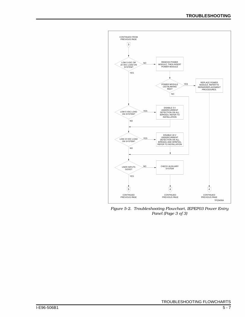
TROUBLESHOOTING
I-E96-506B
Figure 5-2. Troubleshooting Flowchart, IEPEP03 Power Entry Panel (Page 3 of 3)
CONTINUED FROMPREVIOUS PAGE
CONTINUEDPREVIOUS PAGE
CONTINUEDPREVIOUS PAGE
CONTINUEDPREVIOUS PAGE
TP25406A
LOW 5 VDC OR24 VDC LOAD ON
SYSTEM?
LOW 5 VDC LOADON SYSTEM?
LOW 24 VDC LOADON SYSTEM?
USER INPUTSGOOD?
POWER MODULELED BLINKING
RED?
REMOVE POWERMODULE, THEN INSERT
POWER MODULE
REPLACE POWERMODULE. REFER TO
REPAIR/REPLACEMENTPROCEDURES.
DISABLE 5 VUNDERCURRENT
DETECTION ON ALLIEPAS02s. REFER TO
INSTALLATION
DISABLE 24 VUNDERCURRENT
DETECTION ON ALLIEPAS02s AND IEPAF02s.REFER TO INSTALLATION
CHECK AUXILIARYSYSTEM
NO
YES
YES
NO
NO
YES
NO
NO
YES
YES
3
5 4 4
TROUBLESHOOTING FLOWCHARTS
1 5 - 7

SECTION 6 - MAINTENANCE
I-E96-506B
INTRODUCTION
This section contains a modular power system preventivemaintenance schedule and procedures. Doing the preventivemaintenance procedures as scheduled maintains good,dependable modular power system operation.
WARNINGThere are exposed AC and DC connections inside the cabinet.These exposed electrical connections present a shock hazardthat can cause injury or death.
AVERTISSEMENTCette armoire comporte des connexions c.a. et c.c. dénudées.Ces connexions électriques présentent un danger d'électrocu-tion pouvant entraîner des blessures ou la mort.
WARNINGNever clean electrical parts or components with the AC poweron. Doing so exposes you to a fatal electrical shock hazard.
AVERTISSEMENTIl ne faut jamais nettoyer des piècesou des composants élec-triques lorsqu'ils sont sous tension. Cedi présente un risqued'électrocution fatale.
WARNING
If input or output circuits are a shock hazard after disconnect-ing system power at the power entry panel, then the door of thecabinet containing these externally powered circuits must bemarked with a warning stating that multiple power sourcesexist.
AVERTISSEMENT
Si des circuits d'entrée ou de sortie sont alimentés à partir desources externes, ils présentent un risque de choc électriquemême lorsque l'alimentation du système est débranchée dupanneau d'entrée l'alimentation. Le cas échéant, un avertisse-ment signalant la présence de sources d'alimentation multiplesdoit être apposé sur la porte de l'armoire.
WARNING
Wear eye protection whenever working with cleaning solvents.When removing solvents from printed circuit boards usingcompressed air, injury to the eyes could result from splashingsolvent as it is blown off the printed circuit board.
AVERTISSEMENT
Portez toujours des lunettes de protection lorsque vous uti-lisez des solvants de nettoyage. L'aircomprimé servant àenlever le solvant des cartes de circuits imprimés provoquedes éclaboussures qui risquent d'atteindre les yeux.
INTRODUCTION
1 6 - 1

MAINTENANCE ®
This section presents procedures that the customer should beable to perform on site. These preventive maintenance proce-dures should be used as a guideline to assist in establishinggood preventive maintenance practices. Select the minimumsteps required to meet the cleaning needs of your system.
Personnel performing preventive maintenance should meet thefollowing qualifications.
• Maintenance personnel should be qualified electrical tech-nicians or engineers that know the proper use of test equip-ment such as digital multimeters.
• Maintenance personnel should be familiar with the INFI 90modular power system, have experience working with pro-cess control systems, and know what precautions to takewhen working on live AC systems.
PREVENTIVE MAINTENANCE SCHEDULE
Table 6-1 is the preventive maintenance schedule for the mod-ular power system. The table lists the preventive maintenancetasks in groups according to their specified maintenance inter-val. Some tasks in Table 6-1 are self explanatory. Instructionsfor tasks that require further explanation are covered in PRE-VENTIVE MAINTENANCE PROCEDURES in this section.
NOTE: The preventive maintenance schedule list is for general pur-poses only. Your application may require special attention.
Table 6-1. Preventive Maintenance Schedule
Task Frequency
Check the cabinet air filters. Clean or replace them as necessary. Check the air filter more frequently in excessively dirty environments. Refer to procedure.
3 months
Check cabinet, power entry panel and power modules for dust. Clean as necessary using an antistatic vacuum.
Check all signal, power and ground connections within the cabinet and verify that they are secure. Refer to procedure.
Check modular power supply outputs. Refer to procedure. 6 months
Do a visual inspection of the fan assembly. Verify that all fans are rotating and replace if necessary. Refer to the appropriate INFI 90 power system manual for replacement instructions.
Check the quality of the plant power and grounding system. Follow the power and grounding system verification procedures in the INFI 90 site preparation and planning instruction.
12 months
Inspect all control, I/O modules and power modules, giving particular attention to power supply contacts and heat sinks. Clean as necessary. Refer to procedure.
^
Inspect and check the power entry panel. In high vibration environments testing may be necessary at shorter intervals. Refer to procedure.
2 years
PREVENTIVE MAINTENANCE SCHEDULE
6 - 2 I-E96-506B1

MAINTENANCE
I-E96-506B
EQUIPMENT REQUIRED
Following is a list of tools and equipment required for themaintenance procedures.
• Antistatic vacuum.• Digital multimeter.• Flathead torque screwdriver (Newton meters/inch-pounds).• Four-inch flathead screwdriver.• 16-inch flathead screwdriver.• Isopropyl alcohol (99.5% electronic grade).• Foam-tipped swab.• Eberhard Faber (400A) pink pearl eraser or equivalent.• Fiberglass burnishing brush.• Lint-free cloths.• Small needle nose pliers.
PREVENTIVE MAINTENANCE PROCEDURES
This section covers tasks from Table 6-1 that require specificinstructions or further explanation. The tasks and instructionscovered are:
• Cabinet air filter cleaning or replacement.
• How to check signal, power and ground connections.
• Checking modular power supply outputs.
• The power entry panel preventive maintenance procedure.
• Specific instructions on cleaning printed circuit boards andedge connectors.
Refer to Section 7 for instructions on how to replace the fanassembly.
Cabinet Filter Cleaning/Replacement
The cabinet air filter mounts over the lower air vent, inside thecabinet front door. To replace the air filter:
1. Use a flathead screwdriver to remove one screw securingthe mounting plate at the top of the air filter mounting bracket.
Replace power modules. Call Bailey sales and service for information. 5 years
Complete all checks and inspections in this table. Replacement tasks should be done at the scheduled frequency.
Shutdown
Table 6-1. Preventive Maintenance Schedule (continued)
Task Frequency
EQUIPMENT REQUIRED
1 6 - 3

MAINTENANCE ®
2. Pull the mounting bracket (and air filter) off the cabinetdoor.
3. Remove the air filter from its mounting bracket.
4. Either clean or replace the air filter.
5. If the air filter stays dry and relatively clean, use com-pressed air to blow dust and dirt free from the filter.
6. Clean a dirty filter in water and a mild detergent (i.e., dishwashing soap). Agitate the filter or squeeze the soapy waterthrough the filter to remove dirt.
7. When the filter is clean, rinse the filter thoroughly withwater.
8. Air dry the filter before replacing it.
9. Wipe any dust or dirt from the mounting bracket.
10. Return the dry filter to its mounting bracket.
11. Place the mounting bracket into position on cabinet doorand tighten the screw that holds the mounting plate over theair filter mounting bracket.
Checking Connections
NOTE: Power to the cabinet should be off while performing this pre-ventive maintenance task.
Check all signal wiring, power and ground connections withinthe cabinet to verify their integrity. When checking connec-tions, always turn a screw, nut or other fastening device in thedirection to tighten only. If the connection is loose, it will betightened. If the connection is tight, the tightening action willverify that it is secure. There must not be any motion done toloosen the connection.
1. Verify that all phase, neutral and grounding conductorconnections on the power entry panel are secure.
2. Verify that all other power connections within the cabinet,including bus bars and connections to the power supplies aresecure.
3. Verify that all field wiring connections to the terminationunits or termination modules are secure.
PREVENTIVE MAINTENANCE PROCEDURES
6 - 4 I-E96-506B1

MAINTENANCE
I-E96-506B
Checking Power Module Outputs
To check modular power supply outputs on IEPEP01 andIEPEP02 power entry panel systems, check the bus voltages onthe system power bus bar. There are test jacks on the busmonitor module for checking bus voltages on IEPEP03 powerentry panel systems. Appendix C contains complete modularpower system wiring diagrams.
CHECKING BUS VOLTAGES ON IEPEP01 AND IEPEP02 SYSTEMS
1. Verify all power module status LEDs are green.
2. If any of the status LEDs are not green, refer to Section 5 totroubleshoot and correct the problem before proceeding.
3. Measure the bus voltages at the system power bus bar.Appendix C shows wiring diagrams of the IEPEP01 andIEPEP02 power entry panels and bus bars. This test should bedone with the system loaded.
4. Use a digital voltmeter to measure +5, +15, and -15 VDCwith respect to DC common.
5. Measure 24 VDC with respect to I/O common using a digi-tal voltmeter.
6. The measured voltages should be within the specificationsunder module voltage requirements in Table 1-4.
7. If the module bus voltages are not within specification, ver-ify that the system is properly sized. Refer to Appendix B forthe power system sizing procedure.
CHECKING BUS VOLTAGES ON IEPEP03 SYSTEMS
1. Verify all power module status LEDs are green.
2. If any of the status LEDs are not green, refer to Section 5 totroubleshoot and correct the problem before proceeding.
3. Measure the bus voltages at the test jacks on the bus mon-itor module. This test should be done with the system loaded.
4. Use a digital voltmeter to measure +5, +15, and -15 VDCwith respect to DC common.
5. Measure 24 VDC with respect to I/O common using a digi-tal voltmeter.
PREVENTIVE MAINTENANCE PROCEDURES
1 6 - 5
MAINTENANCE ®
6. The measured voltages should be within the specificationsunder module voltage requirements in Table 1-4.
7. If the module bus voltages are not within specification, ver-ify that the system is properly sized. Refer to Appendix B forthe power system sizing procedure.
Power Entry Panel Inspection and Check
This procedure applies to IEPEP01, IEPEP02 and IEPEP03Power Entry Panels. The system must be shut down to performthis maintenance task.
NOTE: Removal of the power entry panel may require two people.
1. Turn off power at the external circuit breakers that feedpower to the power entry panel.
2. Use the 4-inch screwdriver to disconnect all wires andcables from the rear of the power entry panel. Label the wiresaccording to their terminal assignments.
3. Use the 16-inch flathead screwdriver to remove the4 screws (2 on each side) that hold the power entry panel inposition.
4. Remove the power entry panel by sliding it out the back ofthe cabinet.
5. Remove the top cover from the power entry panel by remov-ing the 3 screws securing it at the rear of the power entrypanel.
6. Check the tightness of all power wiring screws within thepower entry panel. Torque all No. 6 screws to 0.90 Newtonmeters (8 in-lbs). Torque all No. 8 screws to 1.58 Newtonmeters (14 in-lbs).
7. Inspect and clean the power entry panel, AC transfer mod-ule and bus monitor module.
8. Replace the power entry panel top cover and install thepower entry panel.
9. Connect all wires and cables removed from the power entrypanel in Step 2.
Printed Circuit Board Cleaning
There are several circuit board cleaning procedures in this sec-tion. These procedures cover circuit board cleaning and wash-ing, cleaning edge connectors and circuit board laminatebetween edge connectors. Use the procedures that meet the
PREVENTIVE MAINTENANCE PROCEDURES
6 - 6 I-E96-506B1

MAINTENANCE
I-E96-506B
needs of each circuit board. Remove all dust, dirt, oil, corrosionor any other contaminant from the circuit board.
Do all cleaning and handling of the printed circuit boards atstatic safe work stations. Always observe the steps in SpecialHandling in Section 3 when handling printed circuit boards.
GENERAL CLEANING AND WASHING
If the printed circuit board needs minor cleaning, remove dustand residue from the printed circuit board surface using clean,dry, filtered compressed air or an antistatic field service vac-uum cleaner.
An alternate method of washing the printed circuit board is:
1. Clean the printed circuit board by spraying or wiping theboard with isopropyl alcohol (99.5% electronic grade). Use afoam tipped swab to apply the alcohol when wiping the board.
2. When the circuit board is clean, remove excess solvent byusing compressed air to blow it free of the circuit board.
EDGE CONNECTOR CLEANING
1. Use a solvent mixture of 80% isopropyl alcohol (99.5% elec-tronic grade) and 20% distilled water.
2. Soak a lint free cloth with the solvent mixture.
3. Work the cloth back and forth parallel to the edge connec-tor contacts.
4. Repeat with a clean cloth that is soaked with the solventmixture.
5. Dry the edge connector contact area by wiping with a cleanlint free cloth.
To clean tarnished or deeply stained edge connector contacts:
1. Use an Eberhard Faber (400A) pink pearl eraser or equiva-lent to remove tarnish or stains. Fiberglass or nylon burnish-ing brushes may also be used.
2. Minimize electrostatic discharge by using the 80/20 iso-propyl alcohol/water solution during burnishing.
3. Do not use excessive force while burnishing. Use onlyenough force to shine the contact surface. Inspect the edgeconnector after cleaning to assure no loss of contact surface.
4. Wipe clean with a lint-free cloth.
PREVENTIVE MAINTENANCE PROCEDURES
1 6 - 7

MAINTENANCE ®
CLEANING FEMALE EDGE CONNECTORS
1. Use a foam tipped swab or a lint free cloth wrapped over apiece of scrap circuit board. Soak the swab or cloth in elec-tronic grade isopropyl alcohol.
2. Insert the swab of cloth covered circuit board into edgeconnector and work it back and forth to clean the contacts.
3. Rinse the edge connector contacts by spraying with isopro-pyl alcohol.
4. Remove excess alcohol and dry using compressed air.
PREVENTIVE MAINTENANCE PROCEDURES
6 - 8 I-E96-506B1

SECTION 7 - REPAIR/REPLACEMENT PROCEDURES
I-E96-506B
INTRODUCTION
Although the modular power system is designed to give long,troublefree service, some components may need to be replacedperiodically. This section explains the replacement proceduresand lists spare part numbers.
SPARE PARTS
Table 7-1 lists a description and Bailey part number of spareparts that can be stocked. It is impractical to specify a recom-mended quantity of spare parts because Bailey Controls Com-pany custom designs every system. Contact Bailey ControlsCompany for help determining the quantity of spare parts tokeep on hand for your particular system.
® Bussman is a registered trademark of McGraw Edison Company.
Table 7-1. Spare Part Numbers and Description
Description Part No./Nomenclature Remarks
AC field power module IEPAF02 Can replace an IEPAF01 module
AC power cables 6637814_2 Connects PEP to PMU or to input power bus bar
6637818_2 Connects input power bus bar to MMU
AC system power module IEPAS02 Can replace an IEPAS01 module
AC transfer module 6637827_1 Used in IEPEP03
Bus monitor module 6637830_1 Used in IEPEP03
Cabinet filter 199914_20 IECAB01and IECAB03
DC power cable 1948509_5 Connects MMU to system power bus bar
Fuse, 1 A Bussman® AGC1 or equivalent 194776A11001
Fuse in IEFAN02 assembly
Fuse, 2 A Bussman AGC2 or equivalent 194776A12001
Fuse in IEFAN01 assembly
Fuse, 3 A Bussman GMA-3 fast act-ing or equivalent 1948182_23001
Fuse in IEPAS02 and IEPAF02 modules
IEFAN01 assembly (120 VAC) 1947419_1 —
IEFAN02 assembly (240 VAC) 1947419_2 —
Insulated quick connect receptacle
1948529_1 —
PFI cable 6638084_1 Connects IEPEP01/02 to system power bus bar
INTRODUCTION
1 7 - 1

REPAIR/REPLACEMENT PROCEDURES ®
AC TRANSFER MODULE REPLACEMENT
NOTES:1. The AC transfer module can be removed under power if lineone is verified operational and within tolerance.
2. The bus monitor module goes off-line when the AC transfermodule is removed. The bus monitor module must be removedfirst . Then remove the AC transfer module.
To replace the AC transfer module:
1. Turn the 2 thumbscrews 1/2-turn to release the bus moni-tor module faceplate. Pull on the faceplate to slide the moduleout.
2. Turn the 2 thumbscrews 1/2-turn to release the AC trans-fer module faceplate. Pull on the faceplate to slide the moduleout.
3. Set switch S1 on the replacement to match the setting ofthe ATM module just removed.
4. Insert the replacement AC transfer module. Grasp it by thefaceplate. Align the top and bottom edges of the circuit boardwith the guides in the panel.
5. Hold the module by the faceplate and slide it into the slot;push until the rear edges are firmly seated in the backplaneconnectors.
6. Reinsert the bus monitor module. Grasp it by the faceplate.Align the top and bottom edges of the circuit board with theguides in the panel.
7. Hold the module by the faceplate and slide it into the slot;push until the rear edges are firmly seated in the backplaneconnectors.
8. Latch both modules in place by turning the faceplatethumbscrews 1/2-turn.
PFI cable(cont.)
6637813_1 Connects IEPEP03 to system power bus bar
Power entry panel IEPEP01 Single AC feed with no circuit breaker
IEPEP02 Single AC feed with circuit breaker
IEPEP03 Redundant AC feed with circuit breakers
Node status output cable 66334205_1 Connects IEPEP01/02/03 to INBIM02 or INPTM01
Table 7-1. Spare Part Numbers and Description (continued)
Description Part No./Nomenclature Remarks
AC TRANSFER MODULE REPLACEMENT
7 - 2 I-E96-506B1
REPAIR/REPLACEMENT PROCEDURES
I-E96-506B
BUS MONITOR MODULE REPLACEMENT
NOTE: The bus monitor module can be removed under power.Replace with another bus monitor module as soon as possible.
To replace the bus monitor module:
1. Turn the 2 thumbscrews on the module faceplate 1/2-turnin either direction to release the module. Slide the module out.
2. Set switch S1 and jumpers J1 through J8 on the replace-ment to match the settings of the BMM module just removed.
3. Grasp the replacement module by the faceplate.
4. Align the top and bottom edges of the circuit board with theguides in the panel.
5. Hold the module by the faceplate and slide it into the slot;push until the rear edges are firmly seated in the backplaneconnectors.
6. Turn the 2 thumbscrews on the module faceplate 1/2-turnto lock the module in place.
FAN ASSEMBLY
Fuse Replacement
1. Disconnect power from the fan assembly by unplugging itfrom J4 on the IEPEP01 or IEPEP02 power entry panel or J1 onthe IEPEP03 power entry panel.
2. Remove the fuse by turning the fuse holder cap counter-clockwise until it releases.
3. Use the fuse holder cap to pull the fuse from its holder.
4. Put an identically rated replacement fuse in the fuse holdercap.
5. Touching only the fuse holder cap, insert the fuse into thefuse holder and turn the fuse holder cap clockwise untilsecure.
6. Connect the fan assembly to power by connecting it to J4on IEPEP01 and IEPEP02 power entry panels or J1 onIEPEP03 power entry panels.
Fan Assembly Replacement
1. Unplug the fan assembly.
BUS MONITOR MODULE REPLACEMENT
1 7 - 3
REPAIR/REPLACEMENT PROCEDURES ®
2. Remove and save the 4 screws on the front of the assemblythat attach it to the cabinet frame.
3. Carefully slide the assembly out of its mounting position.Be careful not to disturb other cabinet wiring.
4. Verify that the replacement assembly has the same ACpower requirements as the one just removed.
5. Slide the replacement assembly into the same spot vacatedby the faulty fan assembly.
6. Secure the fan assembly into its mounting position withthe 4 screws removed in Step 2.
7. Plug the power cord into the connector labeled J1 on thepower entry panel.
8. Listen for fan rotation to verify that the replacement assem-bly is operating.
POWER MODULE
Before replacing IEPAS01 or IEPAF01 power module withIEPAS02 or IEPAF02 power module read the information inAppendix E. Power modules can be removed under power.Always insert a replacement power module before removing apower module.
Power Module Replacement
1. Set the jumper settings on the replacement power module.
2. Grasp the replacement module by its faceplate handle.
3. Align the top and bottom edges of the circuit board with theguides of its slot in the power mounting unit or module mount-ing unit.
4. Hold the module by the faceplate handle and slide it intothe slot; push until the rear edges are firmly seated in thebackplane connectors.
5. Firmly press the module handle while using a flat bladescrewdriver to push and turn the 2 concentric screws 1/2-turnclockwise to lock the module in place.
POWER MODULE
7 - 4 I-E96-506B1
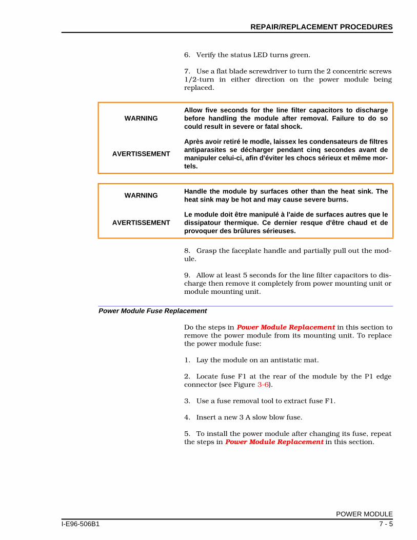
REPAIR/REPLACEMENT PROCEDURES
I-E96-506B
6. Verify the status LED turns green.
7. Use a flat blade screwdriver to turn the 2 concentric screws1/2-turn in either direction on the power module beingreplaced.
8. Grasp the faceplate handle and partially pull out the mod-ule.
9. Allow at least 5 seconds for the line filter capacitors to dis-charge then remove it completely from power mounting unit ormodule mounting unit.
Power Module Fuse Replacement
Do the steps in Power Module Replacement in this section toremove the power module from its mounting unit. To replacethe power module fuse:
1. Lay the module on an antistatic mat.
2. Locate fuse F1 at the rear of the module by the P1 edgeconnector (see Figure 3-6).
3. Use a fuse removal tool to extract fuse F1.
4. Insert a new 3 A slow blow fuse.
5. To install the power module after changing its fuse, repeatthe steps in Power Module Replacement in this section.
WARNINGAllow five seconds for the line filter capacitors to dischargebefore handling the module after removal. Failure to do socould result in severe or fatal shock.
AVERTISSEMENT
Après avoir retiré le modle, laissex les condensateurs de filtresantiparasites se décharger pendant cinq secondes avant demanipuler celui-ci, afin d'éviter les chocs sérieux et même mor-tels.
WARNINGHandle the module by surfaces other than the heat sink. Theheat sink may be hot and may cause severe burns.
AVERTISSEMENTLe module doit être manipulé à l'aide de surfaces autres que ledissipatour thermique. Ce dernier resque d'être chaud et deprovoquer des brûlures sérieuses.
POWER MODULE
1 7 - 5

REPAIR/REPLACEMENT PROCEDURES ®
POWER ENTRY PANEL REPLACEMENT
1. Turn off power to the cabinet at the AC power source.
2. Open the rear door of the cabinet to gain access to the rearof the power entry panel.
3. Remove all wiring from the power entry panel. Label thewires as you remove them.
4. From the rear of the cabinet, use a 16-inch bladed screw-driver to remove the 4 mounting screws.
5. Pull the power entry panel out of the cabinet.
6. From the rear of the cabinet, insert the replacement powerentry panel in the same mounting space.
7. Secure the power entry panel to the cabinet with the 4mounting screws.
8. With power entry panel circuit breakers off, connect thewiring that was removed in Step 3. Appendix C contains powerentry panel wiring diagrams.
9. If it is an IEPEP01 or IEPEP02 panel, check the 120/240 VAC switch to verify that it is set for the correct line volt-age.
10. If it is an IEPEP03 panel, set the jumpers and dipswitcheson the bus monitor module for the desired operation. Verifythat the switch on the AC transfer module is set for the correctline voltage.
11. Turn on the power to the power entry panel at the ACsource.
12. Turn on the power to the cabinet at the power entry panelcircuit breakers and check for proper operation.
WARNING
Verify the main power and power entry panel circuit breakersare turned off before starting installation, retrofit, upgrade, orwiring procedures. Failure to do so could result in severe orfatal shock. Do not turn the power on until the installation, ret-rofit, upgrade, or wiring procedures are complete.
AVERTISSEMENT
Assurez-vous que le disjoncteur d'alimentation principal et ledisjoncteur de panneau d'entrée des alimentations sont éteintsavant de procéder à l'installation, à la mise à jour, à l'extensionou au câblage, dans le but d'éviter les chocs sérieux et mêmemortels. Ne rétablissez pas l'alimentation tant que ces procé-dures ne sont pas terminées.
POWER ENTRY PANEL REPLACEMENT
7 - 6 I-E96-506B1

SECTION 8 - SUPPORT SERVICES
I-E96-506B
INTRODUCTION
Bailey Controls Company is ready to help in the use and repairof its products. Contact your nearest sales office to makerequests for sales, applications, installation, repair, overhauland maintenance contract services.
REPLACEMENT PARTS AND ORDERING INFORMATION
When making repairs at your facility, order replacement partsfrom a Bailey sales office. Provide this information:
1. Part description, part number and quantity.
2. Model and serial numbers (if applicable).
3. Bailey Controls Company instruction manual number,page number and reference figure that identifies the part.
When ordering standard parts, use Bailey Controls Companypart numbers and descriptions. Order parts without commer-cial descriptions from the nearest Bailey Controls Companysales office.
TRAINING
Bailey Controls Company has a modern training facility avail-able for training your personnel. On-site training is also avail-able. Contact a Bailey Controls Company sales office forspecific information and scheduling.
TECHNICAL DOCUMENTATION
Additional copies of this manual, or other Bailey Controls Com-pany manuals, can be obtained from the nearest Bailey Con-trols Company sales office at a reasonable charge.
INTRODUCTION
1 8 - 1

APPENDIX A - QUICK REFERENCE GUIDE
I-E96-506B
INTRODUCTION
Use Table A-1 as a quick reference to check jumper and switchsettings for the IEPAS02 and IEPAF02 Power Modules, busmonitor module and AC transfer module.
Table A-1. Switch and Jumper Setting Reference Guide
DeviceSwitch
PositionJumperPosition
Function
AC transfer module
S1 - 120
S1 - 240
120 VAC operation
240 VAC operation
Bus monitor module
S1 = 0011 Factory default setting, 5, ±15, 24 VDC monitoring enabled. External monitoring disabled.
J1
1-22-42-3
Auxiliary bus monitor, channel 1:
Selects 24 VDC external powerSelects 48 VDC external powerSelects 125 VDC external power
J2
1-22-42-3
Auxiliary bus monitor, channel 2:
Selects 24 VDC external powerSelects 48 VDC external powerSelects 125 VDC external power
J3
1-22-3
AC input voltage, line 2:
Selects 120 VAC input Selects 240 VAC input
J4
1-22-33-4
Auxiliary status input 1:
Normally open status inputNormally closed status inputNot used
J5
1-22-3
Auxiliary status input 2:
Normally open status inputNormally closed status input
J6
1-2 Must be set as shown
J7
1-22-3
AC input voltage, line 1:
Selects 120 VAC input Selects 240 VAC input
J8
2-3 Must be set as shown
INTRODUCTION
1 A - 1

QUICK REFERENCE GUIDE ®
IEPAS02 Power Module
J1
1-22-3
AC input voltage:
120 VAC240 VAC
J2
1-22-3
Enable 24 VDC undercurrent monitoringDisable 24 VDC undercurrent monitoring
J3
1-22-3
Enable 5 VDC undercurrent monitoringDisable 5 VDC undercurrent monitoring
IEPAF02 Power Module
J1
1-22-3
AC input voltage:
120 VAC240 VAC
J2
1-22-3
Enable 24 VDC undercurrent monitoringDisable 24 VDC undercurrent monitoring
Table A-1. Switch and Jumper Setting Reference Guide (continued)
DeviceSwitch
PositionJumperPosition
Function
INTRODUCTION
A - 2 I-E96-506B1

APPENDIX B - MODULE POWER REQUIREMENTS
I-E96-506B
INTRODUCTION
This section lists the power requirements of INFI 90 modules,termination units and termination modules. Use this informa-tion to calculate the +5, +15, -15 and +24 VDC module currentrequirements for each INFI 90 cabinet. The procedure for cal-culating current requirements includes a worksheet for calcu-lating any current requirements for system powered I/O.
After calculating the current requirements for each cabinet,calculate the number of modular power supplies needed foreach cabinet by following the instructions in SIZING THEMODULAR POWER SYSTEM in this section. Finally, follow theprocedure to verify that the total current draw of the powercabinet is within the power entry panel specifications.
CALCULATING CURRENT REQUIREMENTS
Tables B-1 and B-2 contain a list of all INFI 90 modules, termi-nation units and termination modules, and their operatingcurrent requirements. Use Table B-3 to calculate system pow-ered I/O current requirements. To use the information in thesetables:
NOTE: Current consumption values listed in the tables apply to onemodule. Multiply the value of current consumption per module by thenumber of those modules in the cabinet. For example, if a cabinetcontains four IMASI02 modules, the total +5 VDC current consump-tion of these modules is 4 x 85 mA = 340 mA.
1. Make a list of modules contained in the cabinet you are siz-ing for modular power supplies.
2. Calculate the +5 VDC current requirement for eachcabinet.
a. Refer to Table B-1 for the +5 VDC current requirementof each module.
b. Total the +5 VDC current requirement per cabinet.
3. Calculate the +15 VDC current requirement for eachcabinet.
a. Refer to Table B-1 for the +15 VDC current requirementof each module.
b. Total the +15 VDC current requirement per cabinet.
INTRODUCTION
1 B - 1
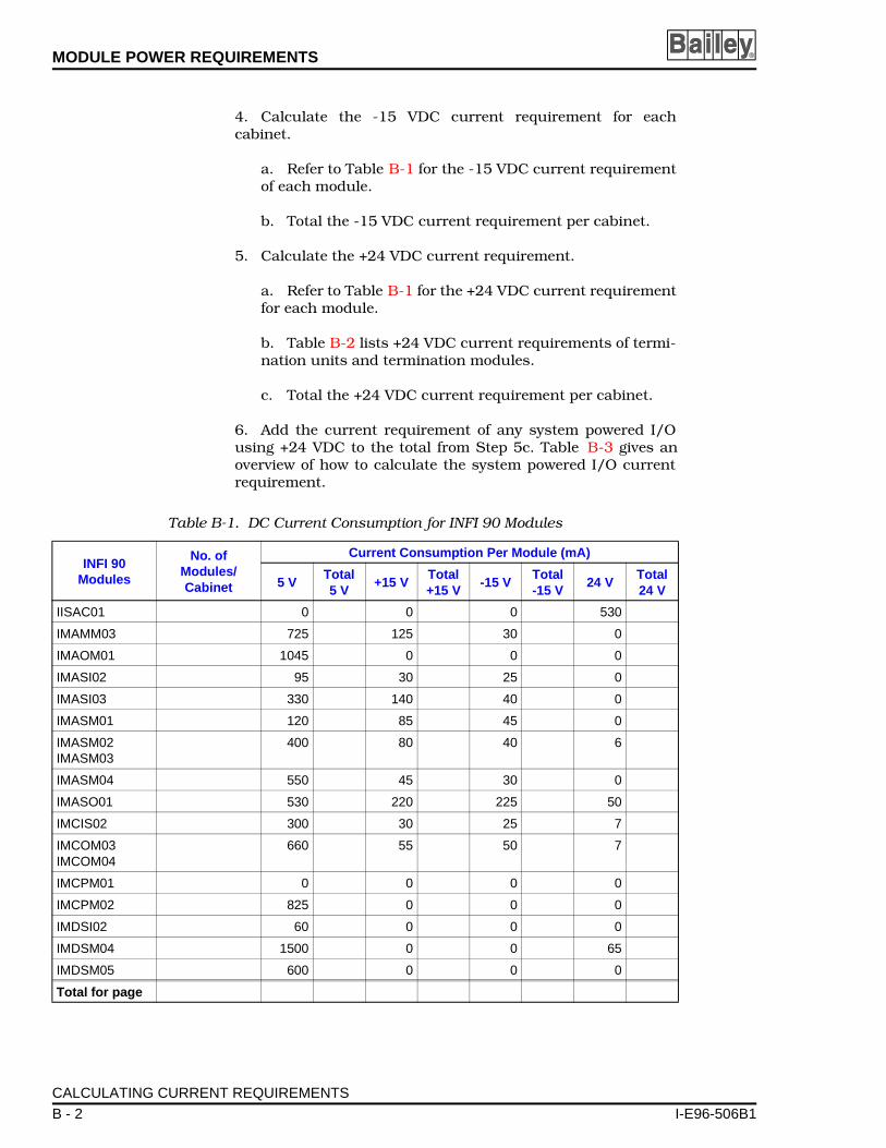
MODULE POWER REQUIREMENTS ®
4. Calculate the -15 VDC current requirement for eachcabinet.
a. Refer to Table B-1 for the -15 VDC current requirementof each module.
b. Total the -15 VDC current requirement per cabinet.
5. Calculate the +24 VDC current requirement.
a. Refer to Table B-1 for the +24 VDC current requirementfor each module.
b. Table B-2 lists +24 VDC current requirements of termi-nation units and termination modules.
c. Total the +24 VDC current requirement per cabinet.
6. Add the current requirement of any system powered I/Ousing +24 VDC to the total from Step 5c. Table B-3 gives anoverview of how to calculate the system powered I/O currentrequirement.
Table B-1. DC Current Consumption for INFI 90 Modules
INFI 90 Modules
No. of Modules/Cabinet
Current Consumption Per Module (mA)
5 VTotal 5 V
+15 VTotal +15 V
-15 VTotal -15 V
24 VTotal 24 V
IISAC01 0 0 0 530
IMAMM03 725 125 30 0
IMAOM01 1045 0 0 0
IMASI02 95 30 25 0
IMASI03 330 140 40 0
IMASM01 120 85 45 0
IMASM02IMASM03
400 80 40 6
IMASM04 550 45 30 0
IMASO01 530 220 225 50
IMCIS02 300 30 25 7
IMCOM03IMCOM04
660 55 50 7
IMCPM01 0 0 0 0
IMCPM02 825 0 0 0
IMDSI02 60 0 0 0
IMDSM04 1500 0 0 65
IMDSM05 600 0 0 0
Total for page
CALCULATING CURRENT REQUIREMENTS
B - 2 I-E96-506B1
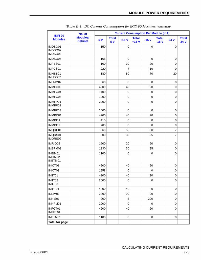
MODULE POWER REQUIREMENTS
I-E96-506B
IMDSO01IMDSO02IMDSO03
150 0 0 0
IMDSO04 165 0 0 0
IMFBS01 100 30 20 0
IMFCS01 220 7 10 0
IMHSS01IMHSS02
180 80 70 20
IMLMM02 660 0 0 0
IMMFC03 4200 40 20 0
IMMFC04 1400 0 0 0
IMMFC05 1000 0 0 0
IMMFP01IMMFP02
2000 0 0 0
IMMFP03 2000 0 0 0
IMMPC01 4200 40 20 0
IMMPI01 415 0 0 0
IMMPI02 700 0 0 0
IMQRC01 660 55 50 7
IMQRS01IMQRS02
300 30 25 7
IMRIO02 1600 20 90 0
IMSPM01 1330 30 25 0
INBIM01INBIM02INBTM01
1100 0 0 0
INICT01 4200 40 20 0
INICT03 1958 0 0 0
INIIT01 4200 40 20 0
INIIT02INIIT03
2000 0 0 0
INIPT01 4200 40 20 0
INLIM03 2200 90 90 0
INNIS01 900 5 200 0
INNPM01 2000 0 0 0
INPCT01INPPT01
4200 40 20 0
INPTM01 1100 0 0 0
Total for page
Table B-1. DC Current Consumption for INFI 90 Modules (continued)
INFI 90 Modules
No. of Modules/Cabinet
Current Consumption Per Module (mA)
5 VTotal 5 V
+15 VTotal +15 V
-15 VTotal -15 V
24 VTotal 24 V
CALCULATING CURRENT REQUIREMENTS
1 B - 3
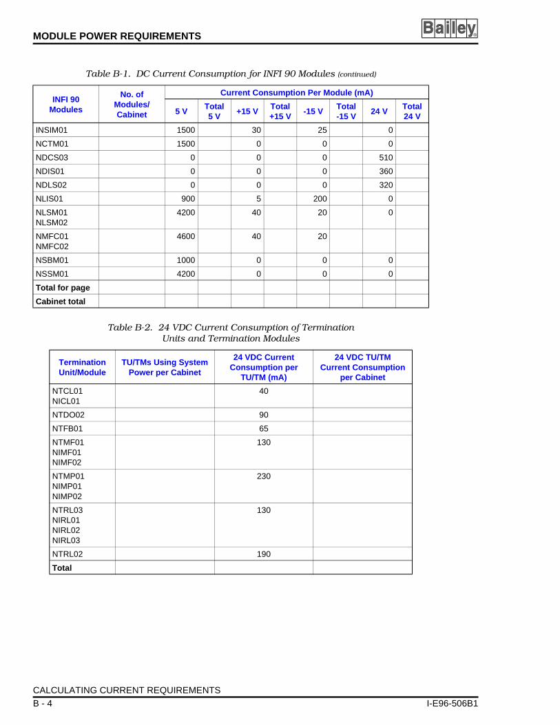
MODULE POWER REQUIREMENTS ®
INSIM01 1500 30 25 0
NCTM01 1500 0 0 0
NDCS03 0 0 0 510
NDIS01 0 0 0 360
NDLS02 0 0 0 320
NLIS01 900 5 200 0
NLSM01NLSM02
4200 40 20 0
NMFC01NMFC02
4600 40 20
NSBM01 1000 0 0 0
NSSM01 4200 0 0 0
Total for page
Cabinet total
Table B-2. 24 VDC Current Consumption of Termination Units and Termination Modules
Termination Unit/Module
TU/TMs Using System Power per Cabinet
24 VDC Current Consumption per
TU/TM (mA)
24 VDC TU/TMCurrent Consumption
per Cabinet
NTCL01NICL01
40
NTDO02 90
NTFB01 65
NTMF01NIMF01NIMF02
130
NTMP01NIMP01NIMP02
230
NTRL03NIRL01NIRL02NIRL03
130
NTRL02 190
Total
Table B-1. DC Current Consumption for INFI 90 Modules (continued)
INFI 90 Modules
No. of Modules/Cabinet
Current Consumption Per Module (mA)
5 VTotal 5 V
+15 VTotal +15 V
-15 VTotal -15 V
24 VTotal 24 V
CALCULATING CURRENT REQUIREMENTS
B - 4 I-E96-506B1

MODULE POWER REQUIREMENTS
I-E96-506B
The total current requirements of system powered analoginputs, analog outputs, digital inputs, digital outputs, andthermocouple inputs make up the system powered I/O currentrequirements. Fill in column two of Table B-3, then multiply itby column three (quantity of inputs or outputs times the cur-rent per input or output). For digital outputs, specify the cur-rent requirements for the digital outputs in your system.Complete the calculation to determine the current require-ments by filling in all five rows as necessary then totaling thecurrent requirements in column four.
SIZING THE MODULAR POWER SYSTEM
The following text and equations explain how to calculate thenumber of IEPAS02 and IEPAF02 power supply modulesneeded for a particular system.
Cabinet requirements for 5 VDC, +15 VDC, -15 VDC and24VDC power are calculated by adding the individual modulecurrent requirements. Refer to CALCULATING CURRENTREQUIREMENTS in this section to determine the currentrequirements of your system. Refer to product specificationsfor current requirements of new modules not listed.
Sizing Systems with IEPAS02 Modules Only
A Total 5 VDC current requirements for system cabinet.
B Total 24 VDC current requirements for associated I/O.
C Total +15 VDC current requirements for system cabi-net.
D Total -15 VDC current requirements for system cabinet.
Q1 Number of IEPAS02 power modules needed to meet5 VDC current requirements.
Table B-3. System Powered I/O Current Consumption
Type ofInput/Output
No. ofInputs/Ouputs
CurrentConsumption per Input/Output (mA)
Total CurrentConsumption forSystem Power I/O
Analog outputs 20
Analog inputs 20
TC inputs 20
Digital inputs 5
Digital outputs NOTE 1
Total I/O current consumptionNOTE:1. Use the typical current requirements of your particular digital outputs.
SIZING THE MODULAR POWER SYSTEM
1 B - 5

MODULE POWER REQUIREMENTS ®
Q2 Number of IEPAS02 power modules needed to meet24 VDC current requirements.
Q3 Number of IEPAS02 power modules needed to meet+15 VDC current requirements.
Q4 Number of IEPAS02 power modules needed to meet-15 VDC current requirements.
Q5 Total power needed.
QS Total number of IEPAS02 power modules needed topower the system.
Then solve the following equations:
QS = Largest of Q1, Q2, Q3, Q4 and Q5.
Round the value of QS to the next highest integer. This numberrepresents the number of IEPAS02 power modules needed tosatisfy system requirements. If using N+1 redundancy, add 1to the value of QS.
System Calculation Example Using IEPAS02 Modules Only
Assume that the current requirements for a set of modulesresiding in a system cabinet has been calculated.
Additionally, the current requirements for 24 VDC I/O powerwas calculated. The results are:
A = 26.5 A (5 VDC current requirement)
B = 3.1 A (24 VDC and associated I/O current)
C = 0.9 A (+15 VDC current requirement)
D = 0.4 A (-15 VDC current requirement)
Q1 A13------=
Q2 B4----=
Q3 C0.8--------=
Q4D
0.8--------=
Q5A 5.225×⟨ ⟩ B 25.8×⟨ ⟩ C 15.3×⟨ ⟩ D 15.3+⟨ ⟩+ + +
130-------------------------------------------------------------------------------------------------------------------------------------=
SIZING THE MODULAR POWER SYSTEM
B - 6 I-E96-506B1

MODULE POWER REQUIREMENTS
I-E96-506B
Substitute these values into the equations and solve for Q.
QS = Largest of Q1, Q2, Q3, Q4 and Q5 = 2.038
Number of power modules required for system.
QS = 2.038
Round the value of QS to the next highest integer.
QS = 3 IEPAS02 modules
With N+1 redundancy where N = QS.
QS(N+1) = 3 + 1 = 4 IEPAS02 modules
For Systems Using Both IEPAS02 and IEPAF02 Modules
Let:
A Total 5 VDC current requirements for system cabinet.
B Total 24 VDC current requirements for associated I/O.
C Total +15 VDC current requirements for system cabi-net.
D Total -15 VDC current requirements for system cabinet.
Q1 Number of IEPAS02 power modules needed to meet 5 Vcurrent requirements.
Q2 Number of IEPAS02 power modules needed to meet 24V current requirements.
Q3 Number of IEPAS02 power modules needed to meet +15V current requirements.
Q126.5
13----------- 2.038= =
Q23.1
4-------- 0.775= =
Q30.9
0.8-------- 1.125= =
Q40.4
0.8-------- 0.5= =
Q526.5 5.225×⟨ ⟩ 3.1 25.8×⟨ ⟩ 0.9 15.3×⟨ ⟩ 0.4 15.3+⟨ ⟩+ + +
130---------------------------------------------------------------------------------------------------------------------------------------------------------=
138.46 79.98 13.77 6.12+ + +⟨ ⟩130
------------------------------------------------------------------------------------ 1.833= =
SIZING THE MODULAR POWER SYSTEM
1 B - 7
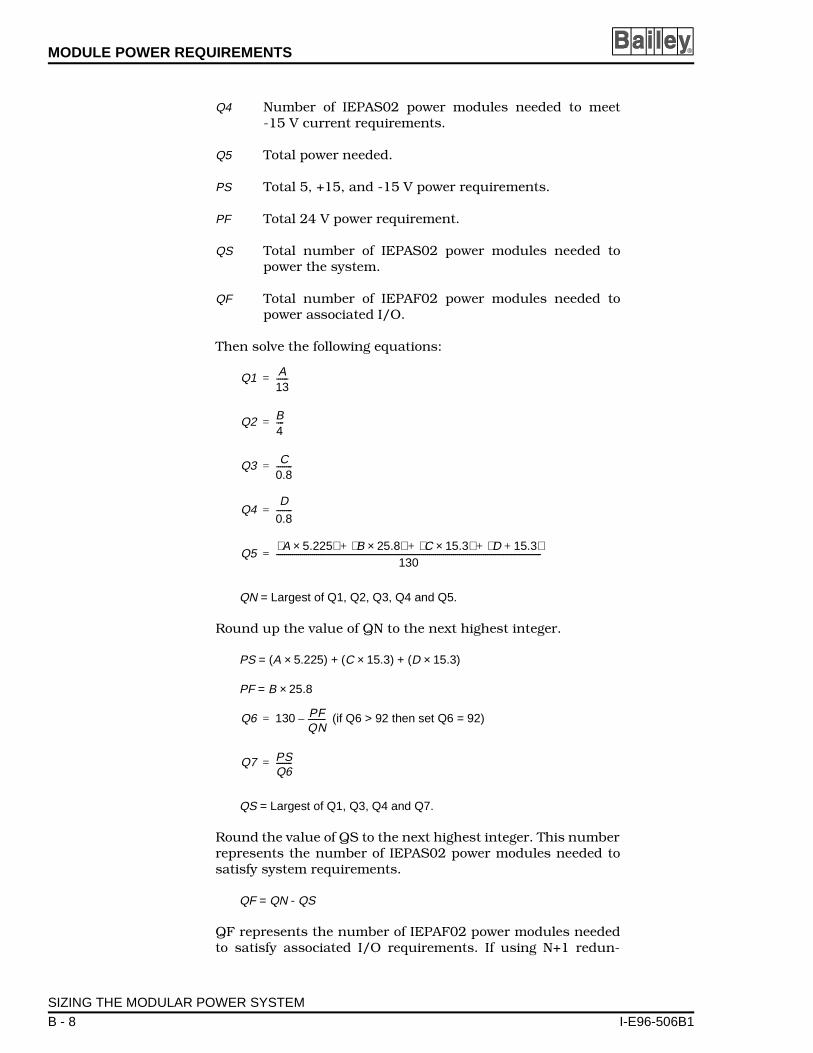
MODULE POWER REQUIREMENTS ®
Q4 Number of IEPAS02 power modules needed to meet-15 V current requirements.
Q5 Total power needed.
PS Total 5, +15, and -15 V power requirements.
PF Total 24 V power requirement.
QS Total number of IEPAS02 power modules needed topower the system.
QF Total number of IEPAF02 power modules needed topower associated I/O.
Then solve the following equations:
QN = Largest of Q1, Q2, Q3, Q4 and Q5.
Round up the value of QN to the next highest integer.
PS = (A × 5.225) + (C × 15.3) + (D × 15.3)
PF = B × 25.8
(if Q6 > 92 then set Q6 = 92)
QS = Largest of Q1, Q3, Q4 and Q7.
Round the value of QS to the next highest integer. This numberrepresents the number of IEPAS02 power modules needed tosatisfy system requirements.
QF = QN - QS
QF represents the number of IEPAF02 power modules neededto satisfy associated I/O requirements. If using N+1 redun-
Q1 A13------=
Q2 B4----=
Q3 C0.8--------=
Q4D
0.8--------=
Q5A 5.225×⟨ ⟩ B 25.8×⟨ ⟩ C 15.3×⟨ ⟩ D 15.3+⟨ ⟩+ + +
130-------------------------------------------------------------------------------------------------------------------------------------=
Q6 130 PFQN---------–=
Q7 PSQ6--------=
SIZING THE MODULAR POWER SYSTEM
B - 8 I-E96-506B1

MODULE POWER REQUIREMENTS
I-E96-506B
dancy, add 1 to the value of QS. The IEPAS02 can supply allthe system voltages.
System Calculation Example Using IEPAS02 and IEPAF02 Modules
Assume that the current requirements for a set of modulesresiding in a system cabinet has been calculated.
Additionally, the current requirement for 24 VDC I/O powerwas calculated. The results are:
A = 26.5 A (5 VDC current requirement)
B = 16 A (24 VDC and associated I/O current requirement)
C = 0.9 A (+15 VDC current requirement)
D = 0.4 A (-15 VDC current requirement)
Substitute these values into the equation and solve for Q.
QN = Largest of Q1, Q2, Q3, Q4 and Q5 = 4.39
Round QN up to the next highest integer.
QN = 5
PS = (A × 5.225) + (C × 15.3) + (D × 15.3)
= (26.5 × 5.225) + (0.9 × 15.3) + (0.4 × 15.3) = 158.35
PF = B × 25.8 = (16 × 25.8) = 412.8
(if Q6 > 92 then set Q6 = 92) = 47.44
QS = Largest of Q1, Q3, Q4 and Q7 = 3.33
Q126.5
13----------- 2.038= =
Q216
4------ 4= =
Q30.9
0.8-------- 1.125= =
Q40.4
0.8-------- 0.5= =
Q526.5 5.225×⟨ ⟩ 16 25.8×⟨ ⟩ 0.9 15.3×⟨ ⟩ 0.4 15.3+⟨ ⟩+ + +
130-------------------------------------------------------------------------------------------------------------------------------------------------------- 4.39= =
Q6 130 PFQN--------- 130 412.8
5---------------–=–=
Q7 PSQ6-------- 158.35
47.44------------------ 3.33= = =
SIZING THE MODULAR POWER SYSTEM
1 B - 9

MODULE POWER REQUIREMENTS ®
Round the value of QS to the next highest integer. This numberrepresents the number of IEPAS02 power modules needed tosatisfy system requirements.
QS = 4
QF = QN - QS = 5 - 4 = 1 IEPAF02 module
Number of IEPAS02 power modules required for the system.
QS = 4 IEPAS02 modules
With N+1 redundancy where N = QS.
QS(N+1) = N + 1 = 5 IEPAS02 modules
MAXIMUM POWER ENTRY PANEL CURRENT DRAW
Use the value of Q5 × 30 (total power from the modular powersystem sizing procedure) to determine if your system is withinspecification of the power entry panel. The following equationsshow how to determine the current draw on the power entrypanel.
for 120 VAC systems.
for 240 VAC systems.
The resulting quotient is the maximum current draw on thepower entry panel. The specified current limits on the powerentry panel are:
• 20 amps for 120 VAC systems.• 10 amps for 240 VAC systems.
Q5 130×47.25
------------------------
Q5 130×94.5
------------------------
MAXIMUM POWER ENTRY PANEL CURRENT DRAW
B - 10 I-E96-506B1

APPENDIX C - WIRING DIAGRAMS
I-E96-506B
INTRODUCTION
Appendix C contains system cabinet wiring diagrams for themodule mounting unit and power mounting unit. Figure C-1shows how to wire the IEPEP03 Power Entry Panel to modulemounting units. Figure C-2 shows how to wire the IEPEP03Power Entry Panel to power mounting units. Figures C-3 andC-4 show how to wire the IEPEP01 and IEPEP02 Power EntryPanels to module mounting units and power mounting unitsrespectively.
INTRODUCTION
1 C - 1

WIRING DIAGRAMS ®
+/L1–/L2
–/L2
+/L1
–/L2
+/L1
THZ
UT POWERBUS BAR
+/L1–/L2
+/L1–/L2
TP25161B
Figure C-1. IEPEP03 Power Entry Panel and Module Mounting Unit Wiring Diagram
(–)(+)
CABLE P/N6637818 2�
CABLE P/N6634205 1�
CABLE P/N 6637813C1(SUPPLIED WITH PEP)
SAFETY GND.CONN. TO CAB.
AC OUT120 VAC240 VAC
120 VAC240 VAC
TB2
TB1
MAIN POWER INPUT120/240 VAC 50/60 HZ
AUX. POWER INPU120/240 VAC 50/60
TB4
TB3
1
1 5
4
4 8
CH2+ –
PWRSYS+ –
BUSVOLT+ –
ALARMSSTATUS
IN1 COM 2
CH1+ –
AUX BUSMONITOR
3
3 7
2
2 6 1
1
J1
J2
6
6
5
5
4
4
3
3
2
2
LL1
LL1
LL1
NL2
NL2
N (L2)L (L1)
L (L1)N (L2)
(VIEW A)
NL2
CABLE P/N 6637814 2(SUPPLIED WITH PEP)
�
NO. 6 AWG GRN/YEL
BRN
BRN
BRN
BRN
BRN
BRN
BLU
BLU
BLU
BLU
BLU
BLU
GRN/YEL
GRN/YEL
GRN/YEL
GRN/YEL
PFI
STATUS
I/O COM+24 V
+5 V
MCOM
MCOM
+15 V–15 V
PFISTATUSI/O COM+24 V
MBUS
MBUS
+5 V
MCOM
+15 V
–15 VPFI
STATUS
STATUS
I/O COM
I/O COM
MCOM
+24 V
+24 V
+5 V
MCOM
+15 V–15 V
+5 V
MCOM
MCOM
+15 V
–15 VPFI
STATUSI/O COM
+24 V
MBUSORN
ORN
WHT/ORN
GRAY
GRAY
GRAY
GRAY
ORN
ORN
BLK
YEL
ORN
WHT/BLU
WHT/ORN
RED
YEL
YEL YEL
WHT
WHT WHT
WHT
MBUS
+5 V
MCOM
+15 V
–15 VPFI
STATUS
I/O COM+24 V
CABLE P/N1948509 5�
CABLE P/N1948509 5�
CABLE P/N1948509 5�
CABLE P/N1948509 5�
SYSTEM POWERBUS BAR
INP
(–)(+)
CABLE P/N6637818 2�
BRNBRN
BLU
BLU
GRN/YEL
GRN/YEL
ISOLATED SYSTEM COMMON BUS
VIEW A
NO. 14 AWG
TO NEXT MMU
NO. 18 AWG (3-WIRE TWISTED)
MODULE MOUNTING UNITIEMMU01/02ROW 3
MODULE MOUNTING UNITIEMMU01/02ROW 2
FAN ASSEMBLYIEFAN01/02ROW 1
POWER ENTRY PANELIEPEP03ROW 0
NO. 10 AWG
USER +24 VOUTPUT
FOR SYSTEMS WITH SINGLE LINE POWER ENTRY
120 VAC240 VAC
TB1 1 2 3 4 5 6
LL1
LL1
NL2
N (L2)L (L1)
MAIN POWERINPUT120/240 VAC50/60 HZ
NL2
BR
N
BLU
GR
N/Y
EL
FANOUTGND
NODE STATUS TO BIM/PTM
STATUS INPUTS
USER ALARM OUTPUTPOWER SYSTEM STATUS
USER ALARM OUTPUTBUS VOLTAGE STATUS
CUSTOMER AUX BUSMONITOR INPUTS
24/48/125 VDC
CH1
CH2
(+)(–)(+)
(–)
(+)
(–)(+)(–)
1COM
2
INTRODUCTION
C - 2 I-E96-506B1

WIRING DIAGRAMS
I-E96-506B
CUSTOMERMONITO
24/48
NODE
USER ALPOWER SYS
USER ALABUS VOLT
W
WHT/BLUWHT/ORN
YEL
O
B
ORN
R
Figure C-2. IEPEP03 Power Entry Panel and Power Mounting Unit Wiring Diagram
AUX BUSMONITOR
4 5 6 7 8
1 COM 2IN
STATUSALARMS
PWRSYS+ - + -
BUSVOLT FAN
OUTGND
(+)
(-)(+)(-)
CH2
CH1AUX BUSR INPUTS/125 VDC
1COM
2
(+)(-)(+)
CABLE P/N 6634205-1
SAFETY GND.CONN. TO CAB.
FAN ASSEMBLYIEFAN01/02 ROW 1
J2
NO. 10 AWG
ISOLATED SYSTEM COMMON BUS
+24 V
I/O COM
MCOM
WHT/ORNGRAYGRAY
GRAY
GRAY
CUSTOMER +24V OUTPUT
NO. 14 AWG
J1TB3
STATUS TO BIM/PTM
ARM OUTPUTTEM STATUS
RM OUTPUTAGE STATUS
STATUSINPUTS
CABLE P/N6637813C1(SUPPLIED WITH PEP)
TP25160B
SYSTEM POWERBUS BAR
L (L1)N (L2) AUX. POWER INPUT
120/240 VAC 50/60 Hz
(SEE VIEW A)
POWER ENTRY PANELIEPEP03 ROW 0
L (L1)
N (L2)
TB1
120 VAC240 VAC
L NL1 L2
CABLE P/N6637814-2
(-)
MCOM
+15 V
-15 V
+5 V
STATUS
I/O COM
+24 V
+5 V
MCOM
+15 V-15 V
PFISTATUS
I/O COM+24 V
+5 V
MCOM+15 V-15 V
HT
CABLE P/N1948509-5
MCOM
+15 V
-15 V
+5 V
PFI
STATUSI/O COM+24 V
MBUSMBUS
MCOM
+5 V
MCOM
+15 V
-15 V
PFISTATUSI/O COM
+24 V
ORN
YEL
WHT
NO. 18 AWG (3-WIRE TWISTED)
PFISTATUS
I/O COM+24 V
GRN/YEL
RN
LK
POWER MOUNTING UNITPMU ROW 2
BLU
BRNN (L2)L (L1)
NO. 10 AWG
6632285A45(BRAIDED WIRE)
MODULE MOUNTING UNITIEMMU01/02 ROW 3
DC IN/COM
24V/48V IN
TO NEXT MMU
NO. 10 AWG (USE ADDITIONAL CONNECTORS IFGREATER THAN 10 AMPS)
120 VAC240 VAC
TB2
L NL1 L2
L NL1 L2
TB1
120 VAC240 VAC
L (L1)N (L2)
FOR SYSTEMS WITH SINGLE LINE POWER ENTRY
VIEW A
MAIN POWERINPUT120/240 VAC50/60 Hz
MAIN POWER INPUT120/240 VAC 50/60 Hz
STATUS
AC OUT
NO. 10 AWG GRN/YEL
CABLE P/N1948509-5
TB4
1 2 3 4 5 6
1 2 3 4 5 6
1 2 3 4 5 6CH1 CH2+ -1 2 3 4
+ -
1 2 3
L NL1 L2
L NL1 L2
ED
INTRODUCTION
1 C - 3
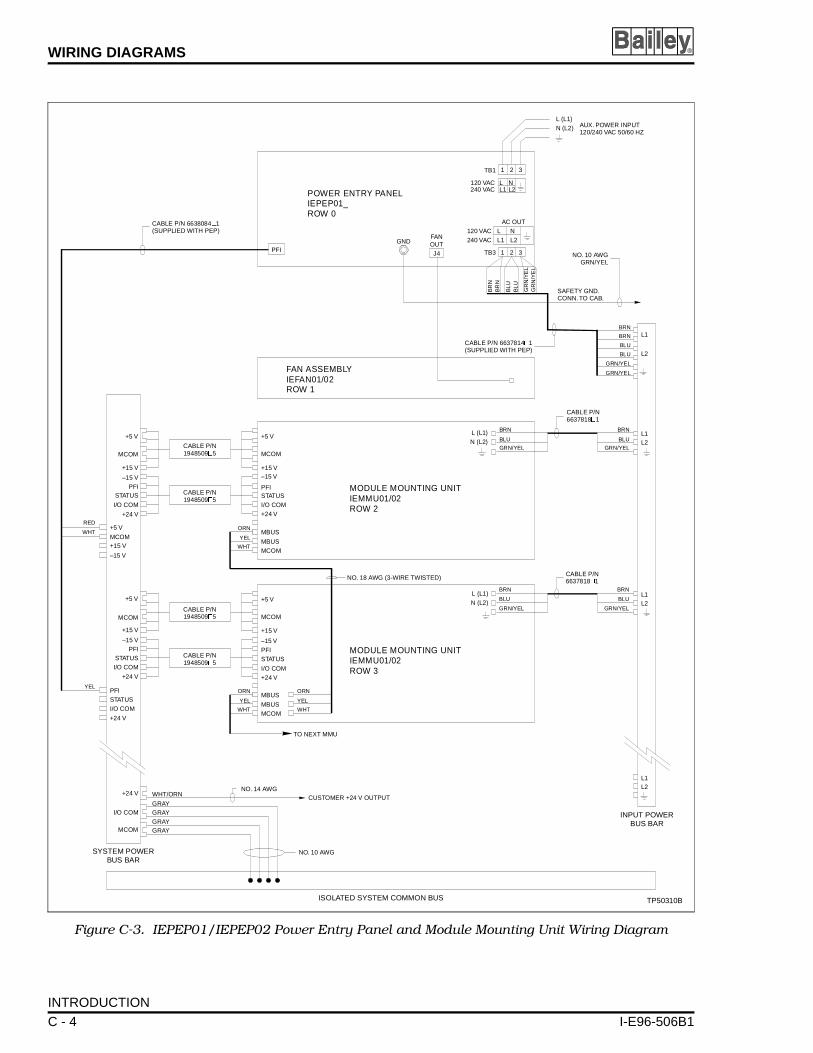
WIRING DIAGRAMS ®
gram
L1
L1
L2
L2
T POWERUS BAR
L1
L1
L2
L2
TP50310B
THZ
Figure C-3. IEPEP01/IEPEP02 Power Entry Panel and Module Mounting Unit Wiring Dia
LL1
LL1
120 VAC240 VAC
120 VAC240 VAC
NL2
NL2
AC OUT
GNDPFI
SAFETY GND.CONN. TO CAB.
CABLE P/N 6637814 1(SUPPLIED WITH PEP)
�
NO. 10 AWGGRN/YEL
BRN
BRN
BLU
BLU
GRN/YEL
GRN/YELFAN ASSEMBLYIEFAN01/02ROW 1
CABLE P/N6637818 1�
BRNBRN
BLUBLU
GRN/YELGRN/YEL
MODULE MOUNTING UNITIEMMU01/02ROW 2
L (L1)N (L2)
L (L1)N (L2)
CABLE P/N6637818 1�
BRNBRN
BLUBLU
GRN/YELGRN/YEL
MODULE MOUNTING UNITIEMMU01/02ROW 3
+5 V
MCOM
+15 V–15 V
PFISTATUSI/O COM+24 V
MBUS
MBUS
MBUS
MBUS
MCOM
MCOM
+5 V
MCOM
+15 V
–15 VPFISTATUS
I/O COM+24 V
PFISTATUSI/O COM
+24 V
+5 V
MCOM
MCOM
+15 V
–15 VPFI
STATUSI/O COM
I/O COM
+24 V
+24 V WHT/ORN
GRAYGRAYGRAYGRAY
CABLE P/N1948509 5�
CABLE P/N1948509 5�
CABLE P/N1948509 5�
CABLE P/N1948509 5�
+5 V
MCOM+15 V
–15 V
RED
WHT
WHT
WHT WHT
YEL
YEL YEL
ORN
ORN ORNYEL
+5 V
MCOM
+15 V
–15 VPFI
STATUS
I/O COM
+24 V
NO. 18 AWG (3-WIRE TWISTED)
TO NEXT MMU
CUSTOMER +24 V OUTPUTNO. 14 AWG
NO. 10 AWGSYSTEM POWERBUS BAR
ISOLATED SYSTEM COMMON BUS
INPUB
TB3
TB1
1
1
3
3
2
2
POWER ENTRY PANELIEPEP01_ROW 0
BR
NB
RN
BL
UB
LU
GR
N/Y
EL
GR
N/Y
EL
FANOUTJ4
AUX. POWER INPU120/240 VAC 50/60
L (L1)N (L2)
CABLE P/N 6638084 1(SUPPLIED WITH PEP)
�
INTRODUCTION
C - 4 I-E96-506B1
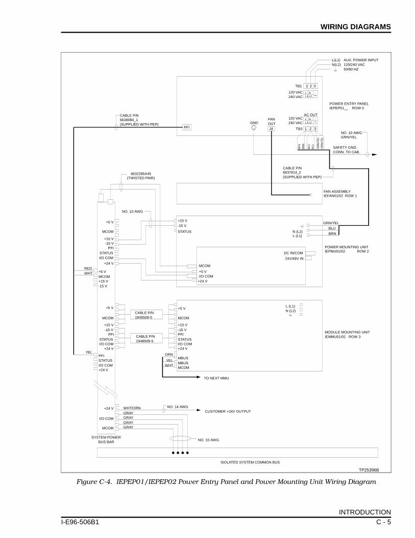
WIRING DIAGRAMS
I-E96-506B
Figur
RED
S
YEL
WHT
e C-4. IEPEP01/IEPEP02 Power Entry Panel and Power Mounting Unit Wiring Diagram
1 2 3TB1
120 VAC240 VAC
L NL1 L2
L(L1)N(L2)
AUX. POWER INPUT120/240 VAC50/60 HZ
120 VAC240 VAC
L NL1 L2
AC OUT
TB3J4
FANOUTGND
SAFETY GND.CONN. TO CAB.
CABLE P/N6637814_2(SUPPLIED WITH PEP)
NO. 10 AWGGRN/YEL
FAN ASSEMBLYIEFAN01/02 ROW 1
POWER MOUNTING UNITIEPMU01/02 ROW 2
+5 V
MCOM
+15 V-15 V
PFISTATUSI/O COM
+24 V
+5 VMCOM+15 V-15 V
L (L1)N (L2)
MCOM
+15 V-15 V
+5 V
PFISTATUSI/O COM+24 V
MBUSMBUSMCOM
+5 V
MCOM
+15 V-15 V
PFISTATUSI/O COM
+24 V
ORN
YELWHT
MODULE MOUNTING UNITIEMMU01/02 ROW 3
NO. 10 AWG
ISOLATED SYSTEM COMMON BUS
+24 V
I/O COM
MCOM
WHT/ORNGRAYGRAYGRAYGRAY
YSTEM POWERBUS BAR
CUSTOMER +24V OUTPUTNO. 14 AWG
TO NEXT MMU
TP25396B
PFISTATUSI/O COM+24 V
PFI
CABLE P/N6638084_1(SUPPLIED WITH PEP)
POWER ENTRY PANELIEPEP01__ ROW 0
6632285A45(TWISTED PAIR)
NO. 10 AWG
MCOM
+15 V-15 V
+5 V
STATUS
I/O COM+24 V
GRN/YEL
BLU
BRNN (L2)L (L1)
DC IN/COM
24V/48V IN
CABLE P/N1948509-5
CABLE P/N1948509-5
1 2 3
INTRODUCTION
1 C - 5
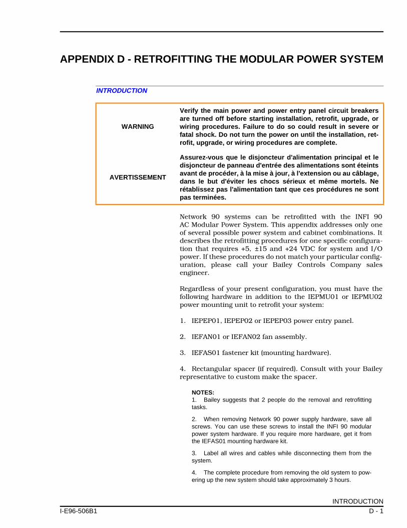
APPENDIX D - RETROFITTING THE MODULAR POWER SYSTEM
I-E96-506B
INTRODUCTION
Network 90 systems can be retrofitted with the INFI 90AC Modular Power System. This appendix addresses only oneof several possible power system and cabinet combinations. Itdescribes the retrofitting procedures for one specific configura-tion that requires +5, ±15 and +24 VDC for system and I/Opower. If these procedures do not match your particular config-uration, please call your Bailey Controls Company salesengineer.
Regardless of your present configuration, you must have thefollowing hardware in addition to the IEPMU01 or IEPMU02power mounting unit to retrofit your system:
1. IEPEP01, IEPEP02 or IEPEP03 power entry panel.
2. IEFAN01 or IEFAN02 fan assembly.
3. IEFAS01 fastener kit (mounting hardware).
4. Rectangular spacer (if required). Consult with your Baileyrepresentative to custom make the spacer.
NOTES:1. Bailey suggests that 2 people do the removal and retrofittingtasks.
2. When removing Network 90 power supply hardware, save allscrews. You can use these screws to install the INFI 90 modularpower system hardware. If you require more hardware, get it fromthe IEFAS01 mounting hardware kit.
3. Label all wires and cables while disconnecting them from thesystem.
4. The complete procedure from removing the old system to pow-ering up the new system should take approximately 3 hours.
WARNING
Verify the main power and power entry panel circuit breakersare turned off before starting installation, retrofit, upgrade, orwiring procedures. Failure to do so could result in severe orfatal shock. Do not turn the power on until the installation, ret-rofit, upgrade, or wiring procedures are complete.
AVERTISSEMENT
Assurez-vous que le disjoncteur d'alimentation principal et ledisjoncteur de panneau d'entrée des alimentations sont éteintsavant de procéder, à la mise à jour, à l'extension ou au câblage,dans le but d'éviter les chocs sérieux et même mortels. Nerétablissez pas l'alimentation tant que ces procédures ne sontpas terminées.
INTRODUCTION
1 D - 1

RETROFITTING THE MODULAR POWER SYSTEM ®
NETWORK 90 POWER SYSTEM REMOVAL
Required Tools
The following tools are needed for the retrofitting procedure:
• 16-inch blade screwdriver.• 1/2-inch nut driver.• Pliers.• Volt/ohmmeter.• Heat gun.
Power Entry Panel Removal
1. Turn the main power feed to the cabinet and circuit break-ers off.
2. Use a voltmeter to test TB5. Verify that no power is present.
3. Disconnect the wiring from TB5 (AC IN).
4. Disconnect the AC wiring from TB2, TB3 and TB4.
5. Disconnect the chassis ground wire from the power entrypanel, but leave it attached to the cabinet and label it. It will beused with the new power entry panel (PEP).
6. Disconnect the 2 monitor connectors from J1 and J2.
7. Disconnect status and cascade connections from TB1 andlabel them.
NOTE: When removing status and cascade connections, identifythem with colored tape or labels. This will help in connecting them tothe new PEP panel.
8. Remove the 4 screws securing the PEP panel to the mount-ing rails.
9. Remove the 2 screws that attach the front of the PEP panelto the support bracket.
10. Remove the plastic nipples (if present) on both sides of thePEP mounting brackets.
11. Push the power entry panel from the front while anotherperson pulls from behind.
NETWORK 90 POWER SYSTEM REMOVAL
D - 2 I-E96-506B1

RETROFITTING THE MODULAR POWER SYSTEM
I-E96-506B
I/O Power Panel Removal
NOTE: If you are removing the I/O power panel by yourself, removethe individual power supplies from the panel first.
1. Disconnect E1 and E2 wires. Remove E2 connection.
2. Disconnect I/O monitor connector from J1.
3. Disconnect 24 VDC and common wiring from TB1, TB2 andTB3. Remove wiring from TB1. Mark wires removed from TB2and TB3.
4. Disconnect and remove AC wiring from TB5.
5. Disconnect cascade and alarm wiring from TB4. Removewiring from TB4-2, TB4-3 and TB4-4.
6. Disconnect and remove all wiring from NPSI03 and NPSI04power supplies.
7. Remove the 4 screws securing the I/O power panel to themounting rails.
8. Pull the I/O power panel out.
Module Power Panel Removal
1. Disconnect and remove heavy strap cables from 5 V andCOMM (E1 through E4) for both power supplies.
2. Disconnect DC wiring from TB1, TB2, TB3, TB4 and TB5.Remove wiring from TB2. Label wires disconnected from TB4and TB5.
3. Disconnect and remove sense (J1, J2) and module monitorout (J3) connectors.
4. Disconnect connections from J4 and J5 and label thecables.
5. Disconnect connections E5 and E6. Disconnect andremove power wiring from supplies.
6. Remove the 4 screws securing each module power supply.Remove power supply.
7. Remove the 4 screws securing the module power panel tothe mounting rails.
8. Pull the module power panel out.
NETWORK 90 POWER SYSTEM REMOVAL
1 D - 3

RETROFITTING THE MODULAR POWER SYSTEM ®
Fan Assembly Removal
1. Disconnect and remove AC wiring from TB1.
2. Disconnect and remove fan status wiring from TB2.
3. Remove the 4 screws securing the fan assembly to themounting rails.
4. Pull the fan assembly out.
NOTE: You will be able to use the +24 VDC wiring and the I/O com-mon cable from the Network 90 installation. Remove the other wiringby cutting the tie wraps that secure it to the sides of the cabinet.
Installing the INFI 90 Power System
Install the INFI 90 power system hardware from the bottom upas explained in Steps 1 through 11.
NOTE: Before mounting the hardware, determine where the speednuts will go. Use a pair of pliers to crimp them onto the mountingrails. All hardware requires 4 screws (2 screws in front, 2 screws inback).
1. Install the row 4 spacer (if required) directly above the firstMMU in your cabinet.
2. Install the power mounting unit (PMU) above the spacerinstalled in Step 1.
3. If a terminal block is present at the top of the cabinet, dothe appropriate wiring.
4. Shape the heavy 0 AWG (MCOM and +5 V) strap cables(part number 6632285_45) in a [ fashion.
5. Attach one end of each cable to its respective cabinet busbar first so as not to stress the PMU bus (see Figures D-1 andD-2).
6. Attach the other ends to the MCOM and +5 VDC bus barsof the power mounting unit.
7. Slide heat shrink tubing over PMU connection (seeFigure 3-8).
8. Insure that connections are properly covered, then use aheat gun to shrink the tubing into place.
9. Install the fan assembly directly above the PMU.
NETWORK 90 POWER SYSTEM REMOVAL
D - 4 I-E96-506B1

RETROFITTING THE MODULAR POWER SYSTEM
I-E96-506B
10. Install the power entry panel directly above the fanassembly.
11. Install row 0 spacer.
Wiring the INFI 90 Power System
NOTE: Before wiring the system, verify the AC transfer module andbus monitor module switch and jumper settings are correct. Refer toSection 3 for switch and jumper setting information; see Figures D-1and D-2 for wiring diagrams of the INFI 90 modular power system ina Network 90 cabinet.
1. Attach one end of the 6 AWG wire assembly to PMU I/OCOM. Attach the other end to the isolated system commonbus.
2. Connect the +24 VDC, originally from TB2 and TB3 of theI/O power panel, to the +24 VDC bus bar on the PMU back-plane by stacking all wires onto a 6 AWG lug (or connect eachwire [6 total] separately).
3. Slide heat shrink tubing over the PMU connection (seeFigure 3-9).
4. Wire the auxiliary status input to TB3 (IEPEP03 panelonly). Refer to the IEPEP03 installation procedure in Section 3for more details.
5. Attach the AC cable (part number 6637814_2) from TB2 onthe IEPEP03 panel or TB3 on the IEPEP01 and IEPEP02 panelsto the AC terminal block on the PMU backplane.
6. Attach the J2 molex connector (part number 6637813_1) tothe J2 socket on the IEPEP03 panel. Attach part number6638084_1 to PFI on the IEPEP01 or IEPEP02 panel.
7. Attach the other ends of the J2 connector (or PFI) as shownin the wiring diagrams (see Figures D-1 and D-2).
8. Connect the status signal wires removed in Step 7 of PowerEntry Panel Removal in this section to TB3-4. Wire COM onTB3-2 to the isolated system common bus bar (IEPEP03 panelonly).
9. Attach any auxiliary bus monitor (24, 48, 125 VDC) inputwires to TB4 (IEPEP03 panel only).
10. Attach fan cable to J4 on IEPEP01 and IEPEP02 panels, orJ1 on IEPEP03 panel.
11. Connect the cabinet ground wire to the ground stud on thePEP panel.
NETWORK 90 POWER SYSTEM REMOVAL
1 D - 5
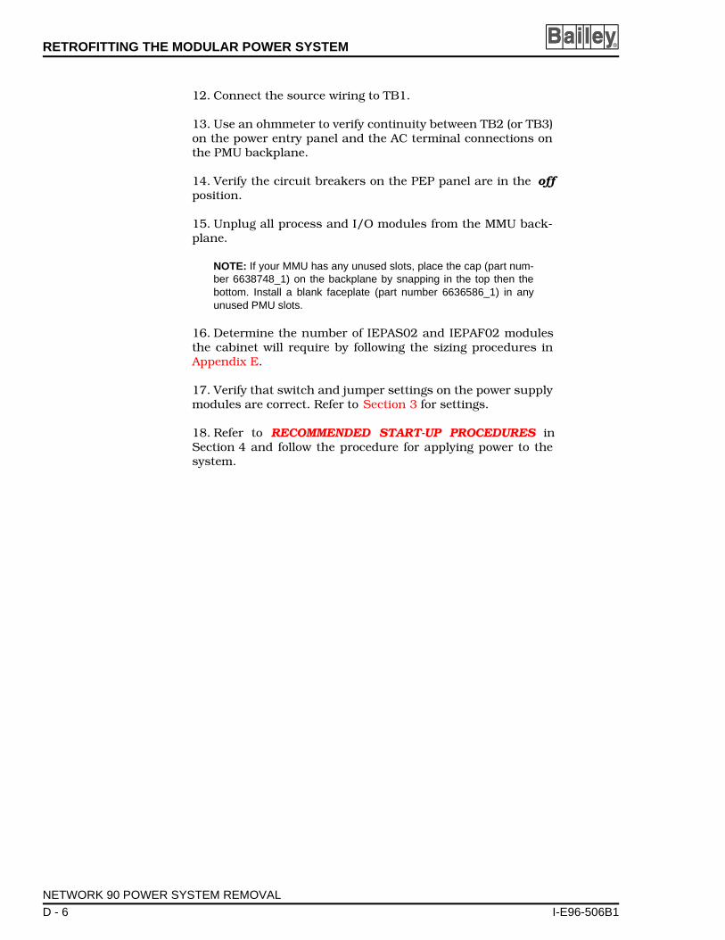
RETROFITTING THE MODULAR POWER SYSTEM ®
12. Connect the source wiring to TB1.
13. Use an ohmmeter to verify continuity between TB2 (or TB3)on the power entry panel and the AC terminal connections onthe PMU backplane.
14. Verify the circuit breakers on the PEP panel are in the offposition.
15. Unplug all process and I/O modules from the MMU back-plane.
NOTE: If your MMU has any unused slots, place the cap (part num-ber 6638748_1) on the backplane by snapping in the top then thebottom. Install a blank faceplate (part number 6636586_1) in anyunused PMU slots.
16. Determine the number of IEPAS02 and IEPAF02 modulesthe cabinet will require by following the sizing procedures inAppendix E.
17. Verify that switch and jumper settings on the power supplymodules are correct. Refer to Section 3 for settings.
18. Refer to RECOMMENDED START-UP PROCEDURES inSection 4 and follow the procedure for applying power to thesystem.
NETWORK 90 POWER SYSTEM REMOVAL
D - 6 I-E96-506B1
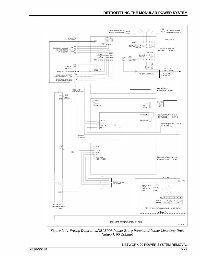
RETROFITTING THE MODULAR POWER SYSTEM
I-E96-506B
Figure D-1. Wiring Diagram of IEPEP03 Power Entry Panel and Power Mounting Unit, Network 90 Cabinet
1 2 3 4
AUX BUSMONITOR
1 2 3 4 5 6 7 8
1 COM 2IN
STATUS ALARMSPWRSYS
BUSVOLT FAN
OUTGND
(+)
(-)(+)(-)
CH2
CH1CUSTOMER AUX BUSMONITOR INPUTS
24/48/125 VDC
1COM
2 CABLE P/N6634205-1
(+)(-)
(+)
SAFETY GND.CONN. TO CAB.
FAN ASSEMBLYIEFAN01/02 ROW 1
J2
ISOLATED SYSTEM COMMON BUS
J1TB3
NODE STATUS TO BIM/PTM
USER ALARM OUTPUTPOWER SYSTEM STATUS
USER ALARM OUTPUTBUS VOLTAGE STATUS
STATUSINPUTS
CABLE P/N6637813C1
TP25397B
NETWORK 90SYSTEM POWER
BUS BAR
L (L1)
N (L2)AUX. POWER INPUT120/240 VAC 50/60 Hz
(SEE VIEW A)
POWER ENTRY PANELIEPEP03 ROW 0
L (L1)N (L2)
TB1
120 VAC240 VAC
CABLE P/N6637814-2
(-)
MCOM
+15 V
-15 V
+5 V
STATUS
I/O COM
+24 V
+5 V
GRN/YEL
POWER MOUNTING UNITIEPMU01/02 ROW 2
BLU
BRNN (L2)L (L1)
6632285A45(BRAIDED WIRE)
DC IN/COM
24V/48V IN
120 VAC240 VAC
TB2
L NL1 L2
L NL1 L2
TB1
120 VAC240 VAC
L (L1)
N (L2)
FOR SYSTEMS WITH SINGLE LINE POWER ENTRY
VIEW A
MAIN POWERINPUT120/240 VAC50/60 Hz
1 2 3 4 5 6
MAIN POWER INPUT120/240 VAC 50/60 Hz
AC OUT
NO. 10 AWG GRN/YEL
TB4
1 2 3 4 5 6
MODULE MOUNTING UNITNMMU01, NMMU02 ROW 3
CUSTOMER 24 VDC OUTPUTNO. 12 AWG
GND
RED
WHT
WHT/BLU
WHT/GRN
+5 V
GND
+15 V-15 V
PFI
MOD BUSMOD BUS COM
GND
+5 V
TO NEXT NMMUNO. 14 AWG
YEL
GND
I/O COM
NO. 6 AWG
1 2 3 4 5 6
LL1
LL1
LL1
+ - + -
CH1 CH2+ - + -
N
N N
L2
L2 L2
NETWORK 90 POWER SYSTEM REMOVAL
1 D - 7
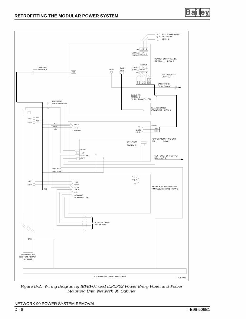
RETROFITTING THE MODULAR POWER SYSTEM ®
Figure D-2. Wiring Diagram of IEPEP01 and IEPEP02 Power Entry Panel and Power Mounting Unit, Network 90 Cabinet
1 2 3TB1
120 VAC240 VAC
L(L1)N(L2)
AUX. POWER INPUT120/240 VAC50/60 HZ
120 VAC240 VAC
AC OUT
1 2 3TB3J4
FANOUT
GND
SAFETY GND.CONN. TO CAB.
CABLE P/N6637814_2(SUPPLIED WITH PEP)
NO. 10 AWGGRN/YEL
FAN ASSEMBLYIEFAN01/02 ROW 1
POWER MOUNTING UNITPMU ROW 2
L (L1)
N (L2)
MODULE MOUNTING UNITNMMU01, NMMU02 ROW 3
ISOLATED SYSTEM COMMON BUSTP25398B
PFI
POWER ENTRY PANELIEPEP01__ ROW 0
CABLE P/N6638084_1
GRN/YEL
BLU
BRNN (L2)L (L1)
DC IN/COM
24V/48V IN
NETWORK 90SYSTEM POWER
BUS BAR
MCOM
+15 V
-15 V
+5 V
STATUS
I/O COM+24 V
+5 V
6632285A45(BRAIDED WIRE)
GND
RED
WHT
WHT/BLU
WHT/GRN
+5 V
GND
+15 V-15 V
PFI
MOD BUSMOD BUS COM
GND+5 V
YEL
GND
BLK
ORN
YEL
TO NEXT NMMUNO. 14 AW G
CUSTOMER 24 V OUTPUTNO. 14 AW G
L1 L2
L N
L1 L2L N
NETWORK 90 POWER SYSTEM REMOVAL
D - 8 I-E96-506B1

APPENDIX E - IEPAS01/IEPAF01 POWER MODULEREPLACEMENT
I-E96-506B
INTRODUCTION
The IEPAS02 and IEPAF02 power modules are compatiblereplacements for the IEPAS01 and IEPAF01 power modulesrespectively. The IEPAS02 and IEPAF02 modules have designenhancements and features that are not available in the previ-ous power modules. The information in this appendix pertainsto replacing IEPAS01 and IEPAF01 power modules withIEPAS02 and IEPAF02 power modules.
REPLACING POWER MODULES
The IEPAS02 module can directly replace the IEPAS01 powermodule in all applications. Because the IEPAS02 can supplymore power, there is no power deficiency when replacing anIEPAS01 module with an IEPAS02 module.
The IEPAF02 module can directly replace the IEPAF01 modulein all applications. The power output of these modules is equal.
POWER SYSTEM SIZING
The IEPAS02 power module can deliver more power than theIEPAS01 module. Refer to Table E-1 to compare total power andcurrent outputs of each module. Because of the difference inload capability, systems using both IEPAS01 and IEPAS02 mod-ules must use the power system sizing procedures for IEPAS01modules (i.e., based on 102 watts output per power module).
LOAD SHARING
All power modules share the same load buses. The load sharingscheme relies on power module voltage outputs being equal.Equal load sharing on a particular bus depends upon the powermodule voltage outputs being equal. A power module with ahigher voltage output will tend to supply more of the load on aparticular bus than its lower voltage output counterparts.
Table E-1. IEPAS01/IEPAS02 Modules Power and Current Outputs
ModuleMaximumPower (W)
Maximum Current Outputs (A)
5 VDC ±15 VDC 24 VDC
IEPAS01 102 10 0.5 4.0
IEPAS02 130 13 0.8 4.0NOTE: The power output capabilities of the IEPAF01 power module and the IEPAF02 power mod-ules are equal.
INTRODUCTION
1 E - 1

IEPAS01/IEPAF01 POWER MODULE REPLACEMENT ®
The IEPAS01 module output voltages are factory adjusted atfull load conditions. These output voltages can show minorchanges because of loading, temperature, component aging,and environment. The IEPAS02 power module does not requirefactory calibration, and will automatically adjust its outputs tocompensate for changes that affect the output voltages. TheIEPAS01 module outputs tend to output a higher voltage thanthe IEPAS02 modules in systems with a light load. Therefore,the remaining IEPAS01 modules will share more of the load asIEPAS02 modules replace them. The IEPAF01 power moduleand IEPAF02 power module exhibit these same characteristics.
SYSTEM EFFECTS ON MODULE LEDS
Replacing an IEPAS01 or IEPAF01 power module with anIEPAS02 or IEPAF02 power module should have no effect onsystem operation. Nevertheless, in some cases replacing anIEPAS01 or IEPAF01 power module with an IEPAS02 orIEPAF02 power module may cause a remaining IEPAS01 orIEPAF01 power module status LED to turn red or blinkinggreen. A red LED may indicate that an output voltage is too lowor an output voltage is too high resulting in an overload condi-tion (earlier versions of the IEPAS01 or IEPAF01 power mod-ule). A blinking green LED on an IEPAS01 or IEPAF01 powermodule indicates an overload condition because the output istoo high. If one of these effects occurs from replacing anIEPAS01 or IEPAF01 power module with an IEPAS02 orIEPAF02 power module, there are two courses of action.
1. Replace the IEPAS01 or IEPAF01 power module with a newIEPAS01 or IEPAF01 power module. Return the overloadingIEPAS01 or IEPAF01 power module to the factory for testingand calibration.
2. Replace the IEPAS01 or IEPAF01 power module with anIEPAS02 or IEPAF02 power module.
NOTE: System integration testing shows that no disruption of cabi-net power occurs when replacing an IEPAS01 or IEPAF01 powermodule with an IEPAS02 or IEPAF02 power module. Always installa replacement power module and verify that it is operating properlybefore removing a power module.
Refer to Appendix A for IEPAS02 and IEPAF02 power modulejumper settings. Refer to Section 7 for power module replace-ment procedures. Enhancements to the IEPAS02 and IEPAF02power modules give the module LEDs additional functionality.Refer to Table 4-2 for a description of IEPAS02 and IEPAF02power module LED states.
SYSTEM EFFECTS ON MODULE LEDS
E - 2 I-E96-506B1
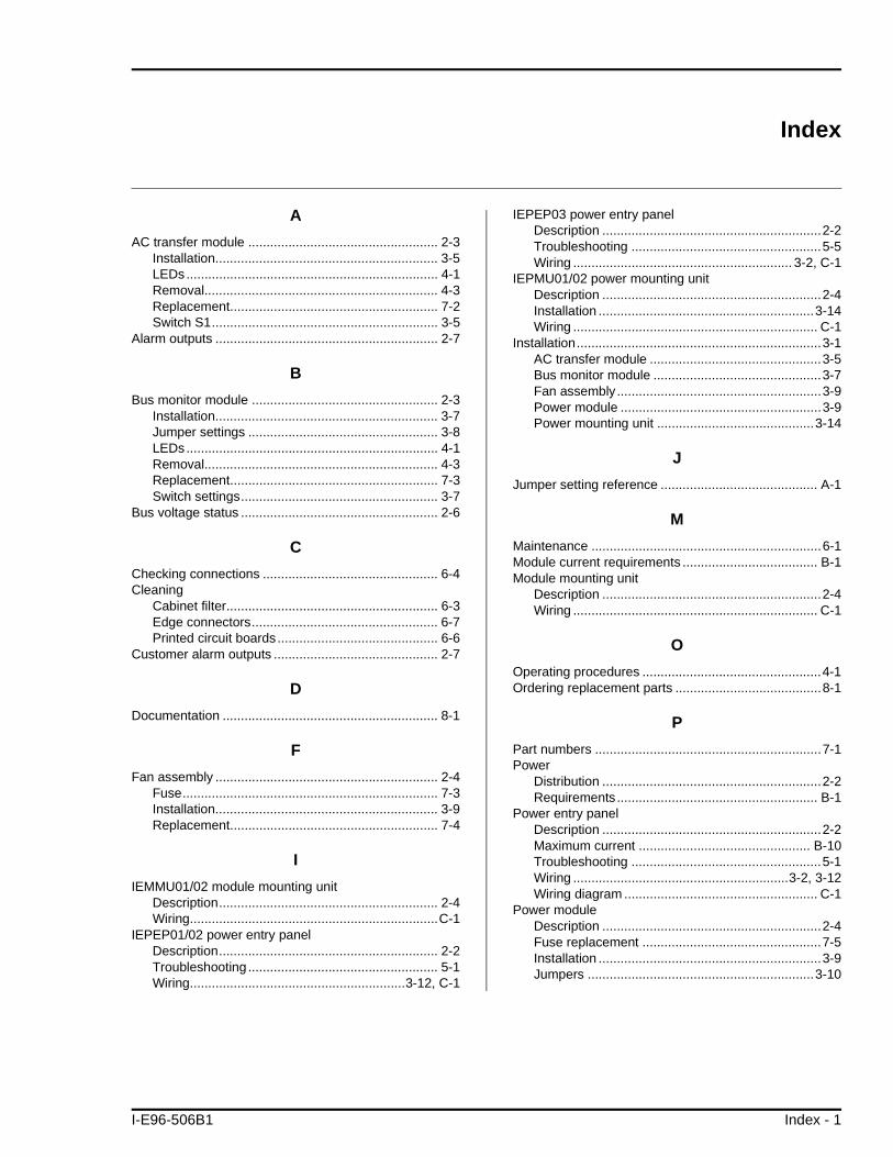
Index
A
AC transfer module .................................................... 2-3Installation............................................................. 3-5LEDs..................................................................... 4-1Removal................................................................ 4-3Replacement......................................................... 7-2Switch S1.............................................................. 3-5
Alarm outputs ............................................................. 2-7
B
Bus monitor module ................................................... 2-3Installation............................................................. 3-7Jumper settings .................................................... 3-8LEDs..................................................................... 4-1Removal................................................................ 4-3Replacement......................................................... 7-3Switch settings...................................................... 3-7
Bus voltage status ...................................................... 2-6
C
Checking connections ................................................ 6-4Cleaning
Cabinet filter.......................................................... 6-3Edge connectors................................................... 6-7Printed circuit boards............................................ 6-6
Customer alarm outputs ............................................. 2-7
D
Documentation ........................................................... 8-1
F
Fan assembly ............................................................. 2-4Fuse...................................................................... 7-3Installation............................................................. 3-9Replacement......................................................... 7-4
I
IEMMU01/02 module mounting unitDescription............................................................ 2-4Wiring....................................................................C-1
IEPEP01/02 power entry panelDescription............................................................ 2-2Troubleshooting .................................................... 5-1Wiring...........................................................3-12, C-1
IEPEP03 power entry panelDescription ............................................................2-2Troubleshooting ....................................................5-5Wiring ............................................................ 3-2, C-1
IEPMU01/02 power mounting unitDescription ............................................................2-4Installation ...........................................................3-14Wiring ................................................................... C-1
Installation...................................................................3-1AC transfer module ...............................................3-5Bus monitor module ..............................................3-7Fan assembly ........................................................3-9Power module .......................................................3-9Power mounting unit ...........................................3-14
J
Jumper setting reference ........................................... A-1
M
Maintenance ...............................................................6-1Module current requirements ..................................... B-1Module mounting unit
Description ............................................................2-4Wiring ................................................................... C-1
O
Operating procedures .................................................4-1Ordering replacement parts ........................................8-1
P
Part numbers ..............................................................7-1Power
Distribution ............................................................2-2Requirements ....................................................... B-1
Power entry panelDescription ............................................................2-2Maximum current ............................................... B-10Troubleshooting ....................................................5-1Wiring ...........................................................3-2, 3-12Wiring diagram ..................................................... C-1
Power moduleDescription ............................................................2-4Fuse replacement .................................................7-5Installation .............................................................3-9Jumpers ..............................................................3-10
I-E96-506B1 Index - 1

Index (continued)
®
LEDs......................................................................4-1Mounting................................................................3-9Operation...............................................................2-1Output verification .................................................6-5Replacement ................................................. 7-4, E-1Sizing procedures................................................. B-1Start-up..................................................................4-3Status ....................................................................2-6Status LEDs ..........................................................4-2Troubleshooting.....................................................5-1
Power mounting unitDescription ............................................................2-4Installation ...........................................................3-14Wiring .......................................................... 3-14, C-1
Power systemRetrofitting procedures......................................... D-1Sizing.................................................................... B-5Status ....................................................................2-5Troubleshooting.....................................................5-1
Preventive maintenance..............................................6-2Procedures ............................................................6-3Required tools .......................................................6-3Schedule ...............................................................6-2
Q
Quick reference guide................................................ A-1
R
Repair/replacement procedures ................................. 7-1Replacement modules................................................E-1Retrofitting Network 90 systems.................................D-1
S
Special handling ......................................................... 3-1Status LEDs................................................................ 4-1Status signals ............................................................. 2-5Switch setting reference .............................................A-1
T
Training....................................................................... 8-1Troubleshooting.......................................................... 5-1
Flowcharts ............................................................ 5-1Power entry panels ............................................... 5-1
U
Unpacking and inspection .......................................... 3-1
W
WiringDiagrams ..............................................................C-1IEPEP01/02 panel .............................................. 3-12Power mounting unit ........................................... 3-14
Index - 2 I-E96-506B1
29801 Euclid Avenue • Wickliffe, Ohio 44092 • (216) 585-8500Telex: 980621 • Telefax: (216) 585-8756 or (216) 943-4609
Elsag Ba ileyProcess Automat io n
For prompt, personal attention to your instrumentation and control needs or a full listing of Bailey representatives in principal cities around the world, contact the Bailey location nearest you.
AustraliaElsag Bailey Pty. LimitedRegents Park, NSWPhone: 61-2-645-3322Telefax: 61-2-645-2212
JapanBailey Japan Company, Ltd.Tagata-Gun, Shizuoka-KenPhone: 81-559-49-3311Telefax: 81-559-49-1114
United KingdomBailey Automation plcTelford, ShropshirePhone: 44-1952-670-477Telefax: 44-1952-670-455
BrazilBailey do BrasilSão PauloPhone: 55-11-548-4122Telefax: 55-11-547-0315
JordanBailey Controls JordanAmmanPhone: 962-6-788-116Telefax: 962-6-756-908
United StatesBailey Controls CompanyWickliffe, OhioPhone: 1-216-585-8500Telefax: 1-216-585-8756
CanadaElsag Bailey (Canada), Inc.Burlington, OntarioPhone: 1-905-639-8840Telefax: 1-905-639-8639
MexicoBailey Mexico S.A. de C.V.NaucalpanPhone: 52-5-557-6100Telefax: 52-5-557-7022
VenezuelaBailey de Venezuela SAValenciaPhone: 58-41-329-196Telefax: 58-41-327-632
FranceElsag Bailey S.A.MassyPhone: 33-1-64-47-2000Telefax: 33-1-64-47-2016
NorwayBailey Norge A.S.BergenPhone: 47-55-222-000Telefax: 47-55-222-010
GermanyBailey-F & P Automation GmbHOverath Phone: 49-220-473-90Telefax: 49-220-473-979
People’s Republic of ChinaBailey Beijing ControlsBeijingPhone: 86-10-401-0651Telefax: 86-10-401-1643
ItalyElsag BaileyGenoaPhone: 39-10-658-1Telefax: 39-10-658-2941
SingaporeElsag Bailey Pte. Ltd.SingaporePhone: 65-442-3200Telefax: 65-442-2700
Form I-E96-506B1 Litho in U.S.A. 194Copyright © 1994 by Elsag Bailey Process Automation, As An Unpublished Work® Registered Trademark of Elsag Bailey Process Automation™ Trademark of Elsag Bailey Process Automation