AC electric circuits 1.More difficult than DC circuits 2. Much more difficult than DC circuits 3....
45
AC electric circuits 1.More difficult than DC circuits 2. Much more difficult than DC circuits 3. You can do it!
-
Upload
augustine-summers -
Category
Documents
-
view
226 -
download
0
Transcript of AC electric circuits 1.More difficult than DC circuits 2. Much more difficult than DC circuits 3....

AC electric circuits
1.More difficult than DC circuits
2. Much more difficult than DC circuits
3. You can do it!

DC: Direct current
AC: Alternating current: amplitude and direction vary with time.
There are many situations where working with AC is more effective. For example,AC signal can be stepped up or down using a transformer. (Amp—Speakers)
AC voltage over time
To measure the voltage:Peak voltage dependson peak shape.AC is not necessarily sine waves

AC signal of various forms and looks

RMS: Root mean squarevalue
For a sine wave
€
V =Vm sinωt
€
Vrms =Vm2

AC Phase
Two signals out of step with each other
A leads B by 45 degrees


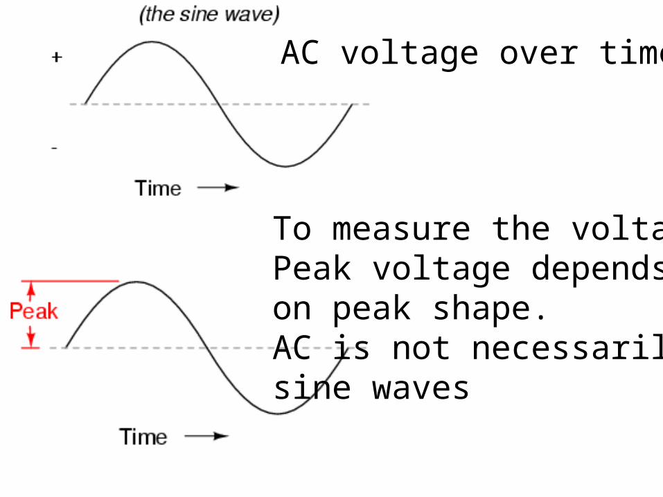
AC resistor circuits
Voltage and current in phase€
ET = E0 sinωt
I =ETR=E0Rsinωt
Power = I V, always positive.Resistors always consumes energy
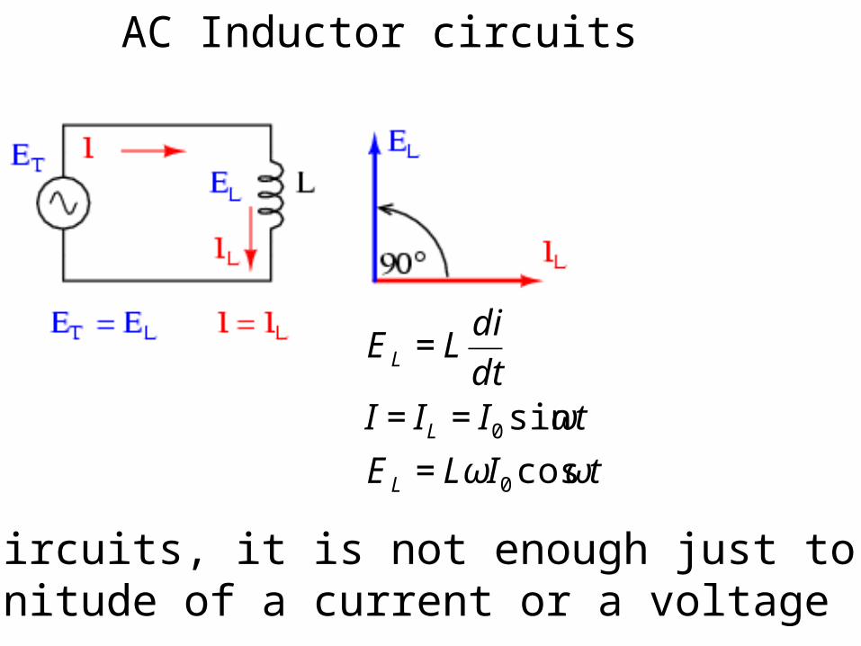
AC Inductor circuits
€
EL = Ldi
dtI = IL = I0 sinωt
EL = LωI0 cosωt
In AC circuits, it is not enough just to state the magnitude of a current or a voltage
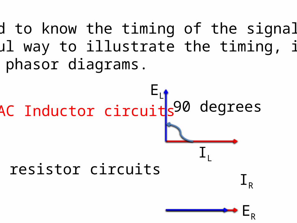
We need to know the timing of the signals.A useful way to illustrate the timing, is the Use of phasor diagrams.
IL
EL90 degreesAC Inductor circuits
AC resistor circuitsIR
ER

Current lags voltage by 90 degrees
€
EL = Ldi
dtI = IL = I0 sinωt
EL = LωI0 cosωt


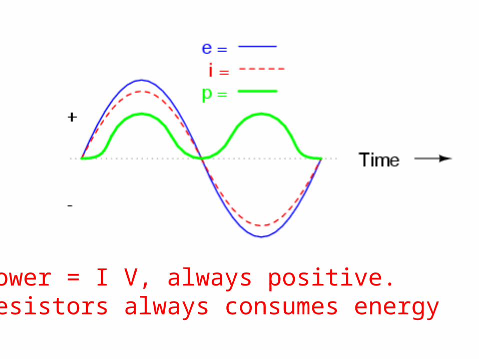
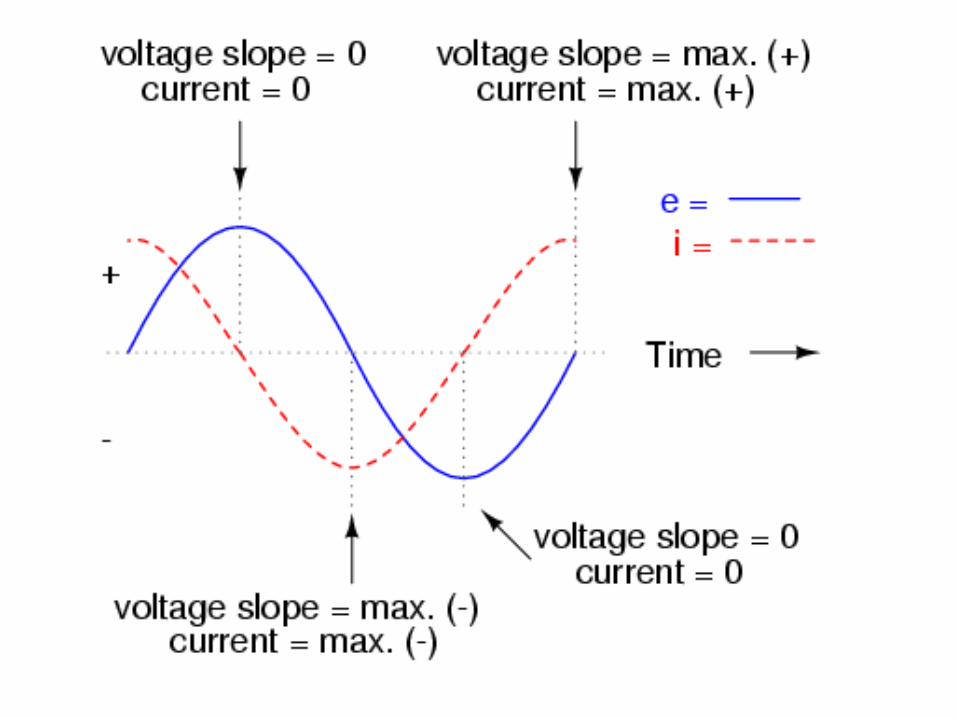
The instantaneous power can be negative! i.e. The inductor absorbs power, as well as releases power.

When I and V are both positive, P is positive.When I and V are both negative, P is also positive.Since I and V are 90 degrees out of phase, There are times when one of them is positive,the other is negative, thus P is negative.
When P is positive, inductor absorbs power, when P is negative, it releases power.

For a pure inductive circuit, the average power consumption is
Zero
Compare with R, which passively consumespower, L is a reactive load.
€
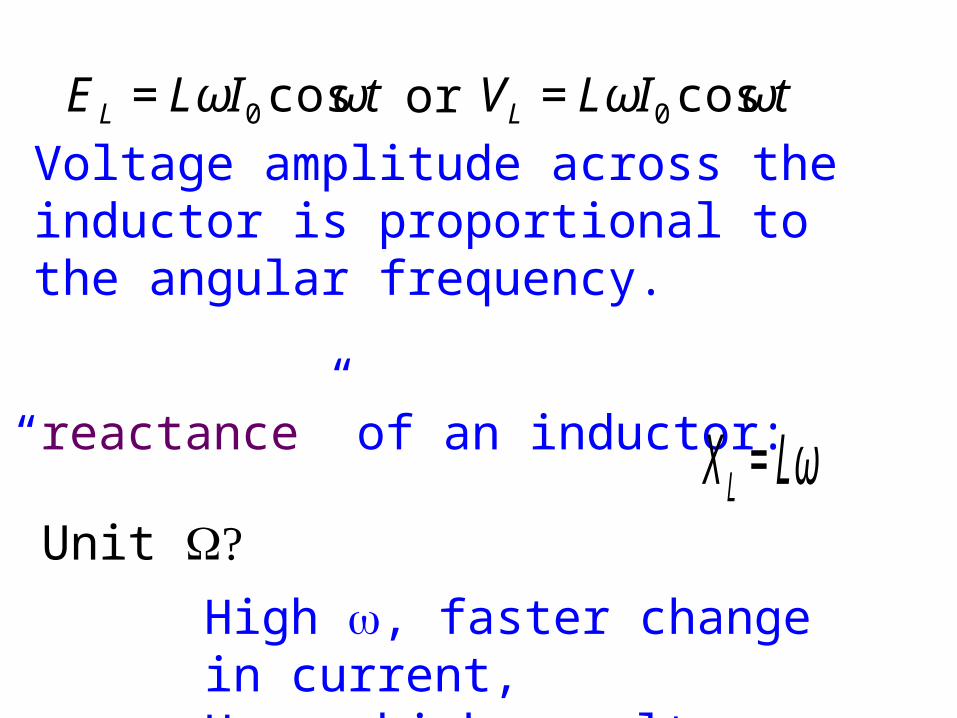
EL = LωI0 cosωt
Voltage amplitude across the inductor is proportional to the angular frequency.
The “reactance” of an inductor:
€
XL = Lω
High w, faster change in current,Hence higher voltage.
Unit ?W
€
VL = LωI0 cosωtor

The reactance has two important components:1) Its magnitude:Which relates the amplitude of the current to that of the voltage.
2) It controls the phase difference between the current and the voltage.
€
XL = Lω
€
Vp = IpLω

Reactance of L: XL=3.7699W
€
I =10V
3.7699Ω= 2.6526A
€
reac tance =Voltage
Current=Voltage∠900
Current∠00
€
Reac tance = 3.7699Ω∠900
€
Reac tance = 3.7699Ω∠900
€
EL = LωI0 cosωt
This is the amplitude of current
XL has a magnitude Lw, and carries a phase 90 degrees
Compare with resistance,The inductance is an active component.The amplitude and the phase of the current are controlled by the property of L

€
XL = 0 + j3.7699Ω
We use j to indicate the phase of the reactance
reactanceR
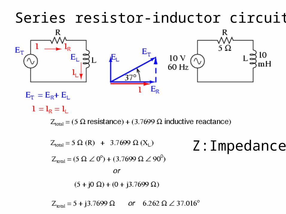
Series resistor-inductor circuits
Z:Impedance
€
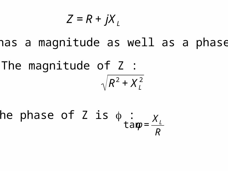
Z = R + jXL
Z has a magnitude as well as a phase
The magnitude of Z :
€
R2 + XL2
The phase of Z is f :
€
tanφ =XLR

Impedance Z= R+jXL
Ohm’s law for AC circuits
€
V = IZ
I =V
Z

For the circuit
€
I =V
Z
We choose V has zero phase
€
I =V
Z=
10V∠00
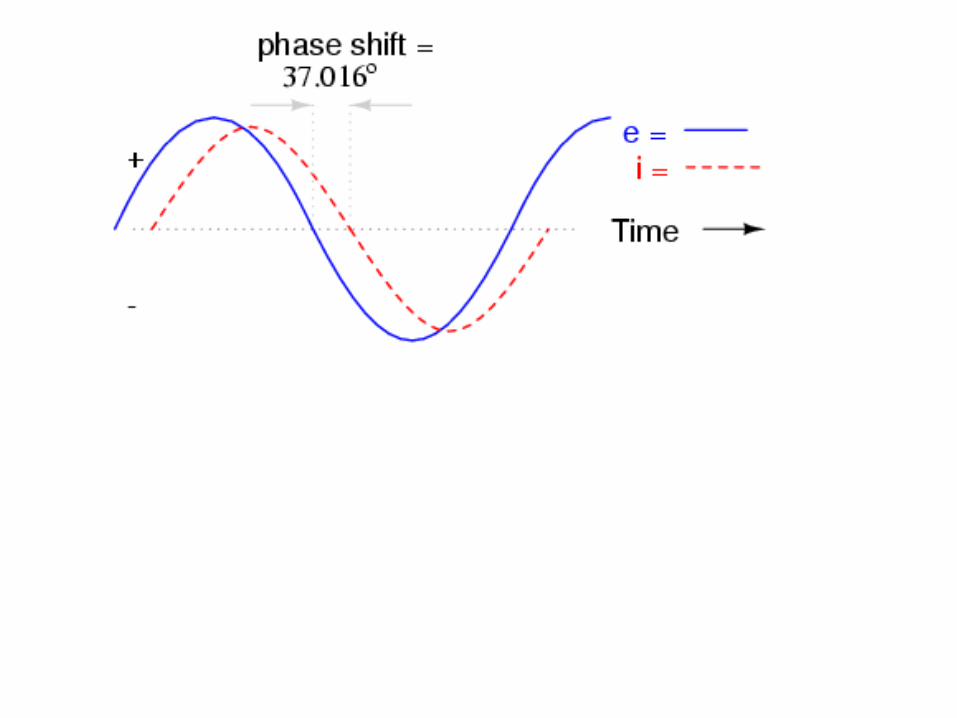
6.26Ω∠37.0160=1.597A∠− 37.0160
Current lags voltage by 37 degrees, less than 90 degrees for the pure inductance circuit. This is because of the effect of the resistor. RL time constant depends on R.
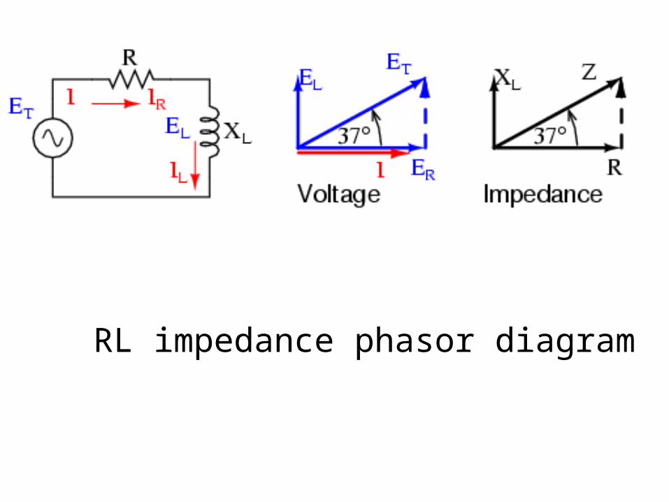
RL impedance phasor diagram

Parallel R-L circuits
€
ZT =1
1
Z1+1
Z2+1
Z3+ ...

€
1
Z1=1
R= 0.2
€
1
Z2=1
jωL=
1
j2π ×60 ×10−2=
1
j3.77
€
1
Z1+1
Z2= 0.2 +
1
j3.77=1
Z
€
I =V
Z=V
Z=10 × (0.2 +
1
j3.77) =10 × (0.2 −
j
3.77) = 2 − j2.65
€
I =V
Z= 3.31< −530
or

AC capacitive circuits
€
Ic =CdV
dtif
V =V0 sinωt, then
Ic =CdV
dt=V0Cωcosωt


€
Ic =CdV
dt=V0ωCcosωt = I0 cosωt
XC =V0I0=1
ωC
Capacitive reactance
The phase of XC is -90 degrees.

€
XC = 26.53Ω
I =10V
26.53Ω= 0.38
€
opposition =Voltage
Current=Voltage∠00
Current∠900=10V∠00
0.378∠900= 26.53Ω∠−900
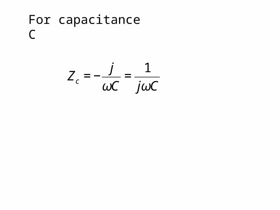
For capacitance C
€
Zc = −j
ωC=1
jωC

Series RC
€
ZT = 5 +1
j2π ×60 ×10−4= 5 − j2.63

Parallel RC
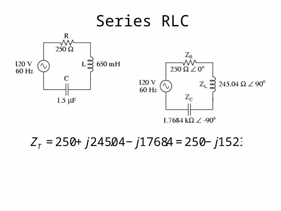
Series RLC
€
ZT = 250 + j245.04 − j1768.4 = 250 − j1523

In general, for series RLC circuits:
€
ZT = R + jωL +1
jωC= R + jωL −
j
ωC= R + j(ωL −
1
ωC)
R is independent of frequency.The imaginary part is frequency dependent,and it equals to zero when
€
ωL = 1
ωC
€
ω =1
LC

€
ω =1
LC
€
ZT = R
When
The impedance is purely resistive
The impedance is minimumSo the current flowing in the circuit reaches maximumUnder such a condition, we say the circuitIs in resonance.

€
ω =1
LC
is the resonance angular frequency for thecircuit.
€
ZT = R + jωL +1
jωC= R + jωL −
j
ωC= R + j(ωL −
1
ωC)
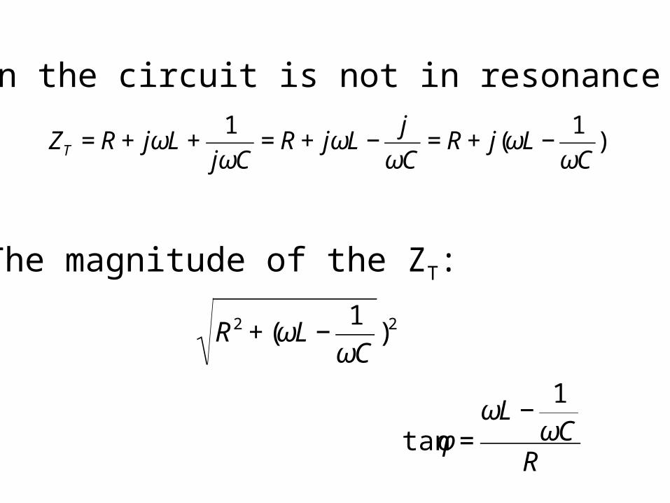
When the circuit is not in resonance
The magnitude of the ZT:
€
tanφ =ωL −
1
ωCR€
R2 + (ωL −1
ωC)2


Resonance