AC 800M High Integrity - -AoteWell Automation … 7 Safety Summary (continued) Warnings related to...
142
Industrial IT 800xA - Safety System Version 4.1 Safety Manual AC 800M High Integrity
Transcript of AC 800M High Integrity - -AoteWell Automation … 7 Safety Summary (continued) Warnings related to...

IndustrialIT800xA - Safety
System Version 4.1
Safety ManualAC 800M High Integrity


IndustrialIT800xA - Safety
System Version 4.1
Safety ManualAC 800M High Integrity

NOTICEThe information in this document is subject to change without notice and should not beconstrued as a commitment by ABB. ABB assumes no responsibility for any errors thatmay appear in this document.
In no event shall ABB be liable for direct, indirect, special, incidental or consequentialdamages of any nature or kind arising from the use of this document, nor shall ABB beliable for incidental or consequential damages arising from use of any software or hard-ware described in this document.
This document and parts thereof must not be reproduced or copied without written per-mission from ABB, and the contents thereof must not be imparted to a third party nor usedfor any unauthorized purpose.
The software or hardware described in this document is furnished under a license andmay be used, copied, or disclosed only in accordance with the terms of such license.
This product meets the requirements specified in EMC Directive 89/336/EEC and in LowVoltage Directive 72/23/EEC.
Copyright © 2005 by ABB. All rights reserved. Release: May 2005Document number: 3BNP004865R4101
TRADEMARKSRegistrations and trademarks used in this document include:
Windows Registered trademark of Microsoft Corporation.
ActiveX Registered trademark of Microsoft Corporation.
PostScript Registered trademark of Adobe Systems Inc.
Acrobat Reader Registered trademark of Adobe Systems Inc.
Industrial IT Trademark of ABB.

3BNP0
Safety Summary
Electrostatic Sensitive DeviceDevices labeled with this symbol require special handling precautions as described in the installation section.
GENERAL WARNINGS
Equipment EnvironmentAll components, whether in transportation, operation or storage, must be in a noncorrosive environment.A complete overview of environmental conditions is given in the user manuals 800xA - Control and I/O, AC 800M Controller Hardware and Control IT S800 I/O, General Information and Installation.
Electrical Shock Hazard During MaintenanceDisconnect power or take precautions to insure that contact with ener-gized parts is avoided when servicing.
Network SecurityThe 800xA system must be protected against deliberate, illegal intrusion.It is the responsibility of the user of the safety system to establish and maintain adequate network security measures adapted to the level of openness in the particular installation.
04865R4101 5
Safety Summary (continued)
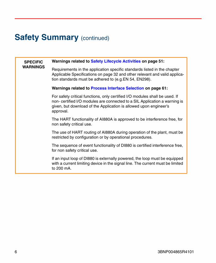
SPECIFICWARNINGS
Warnings related to Safety Lifecycle Activities on page 51:
Requirements in the application specific standards listed in the chapter Applicable Specifications on page 32 and other relevant and valid applica-tion standards must be adhered to (e.g.EN 54, EN298).
Warnings related to Process Interface Selection on page 61:
For safety critical functions, only certified I/O modules shall be used. If non- certified I/O modules are connected to a SIL Application a warning is given, but download of the Application is allowed upon engineer’s approval.
The HART functionality of AI880A is approved to be interference free, for non safety critical use.
The use of HART routing of AI880A during operation of the plant, must be restricted by configuration or by operational procedures.
The sequence of event functionality of DI880 is certified interference free, for non safety critical use.
If an input loop of DI880 is externally powered, the loop must be equipped with a current limiting device in the signal line. The current must be limited to 200 mA.
6 3BNP004865R4101

3BNP0
Safety Summary (continued)
Warnings related to Power Supply on page 64:
The AC 800M HI and the connected S800 I/O system (including field power) must be supplied from a SELV or PELV power supply connected through the power voter SS823.
Older versions of AI880 (PR:B), DI880 (PR:B) and DO880 (PR:C), includ-ing field power, must be supplied from the SD821, SD822 or SD823 power supplies connected through the power voter SS823. (This restric-tion is not valid for AI880A and newer versions of DI880 and DO880).
If any field device connected to the AC 800M HI is externally powered, the device must be supplied from a SELV or PELV power supply connected through the power voter SS823. Exception: When externally powered transmitters are connected to the analog input module AI880/AI880A via a fuse rated 60V/<= 0.1A, the SS823 can be omitted. This is valid for loops up to SIL2.
Warnings related to Operator Interface on page 65:
If used, the Reset all Forces input must be connected to an impulse type panel button.
Warnings related to Maintenance/Engineering Interface on page 67:
If a multi user engineering environment is established, procedures must be in place to avoid that two users are doing modifications to the same data entity simultaneously.
04865R4101 7

Safety Summary (continued)
Warnings related to Software Architecture on page 71:
For all safety critical Applications, correct SIL must be selected in Control Builder M Professional.
The function block types MMSConnect, MMSDef4Bool1, MMSDef4BoolIO1, MMSDef4Dint1, MMSDef4DintIO1, MMSDef4Real1, MMSDef4RealIO1, MMSRead4Bool1, MMSRead4BoolIO1, MMSRead4Dint1, MMSRead4DintIO, MMSRead4Real1 and MMSRead4RealIO1, for communication between controllers, are allowed used in SIL classified applications, but the data communicated cannot be used for safety critical functions.
For exchanging safety critical data between Applications, the Control Modules MMSDef2DwordM and MMSRead2DwordM must be used. The Valid parameter of the MMSRead2Dword shows whether the data can be trusted, and must be used by the application to bring the related safety functions to safe state.
When establishing a safety critical communication link, the UniqueID parameter must be identical in the MMSDef2DwordM and MMSRead2DwordM. The UniqueID must be unique in the whole plant network.
If a SIL classified Application reads data from a non-SIL classified Appli-cation, this data must not be used in any way that can interfere with the safety action of the SIL classified Application.
8 3BNP004865R4101

3BNP0
Safety Summary (continued)
When safety critical signals are communicated between Applications (in the same or different controllers), the FDRT of the communication sub-system must be configured to match the process safety time of the con-trolled process. Requirements for process safety time given in relevant application standards (e.g. EN 298) must be considered and fulfilled.
In Applications where inputs reside in other Applications (and other con-trollers), the design must take into consideration the possibilities that the “remote” inputs can be forced independent of the Force Control setting of the “local” Application.
A philosophy of using either positive or negative logic must be established and followed consistently for the whole plant. Naming of variables should reflect this philosophy to avoid confusion.
A philosophy for using retain/cold retain values must be developed based on the characteristics of the process to be controlled. The philosophy must be followed consistently for the whole plant.
The application program must contain mechanisms to achieve the desired behavior of the safety outputs after a power failure (automatic restart of the process is normally not desired).
The application program must be designed to handle faulty input and out-put signals in accordance with the safety requirements for the plant.
Warnings related to Programming Languages and Libraries on page 77:
The out parameter CondState of the library types AlarmCond, Alarm-CondBasic, AlarmCondM and AlarmCondBasicM shall not be used in a way that can influence the safety functions of a SIL classified application.
If a faceplate with possibility for operator changes to objects in a SIL clas-sified application shall be created, the guidelines for Confirmed Write sup-port in chapter Access Management Settings on page 93 must be followed.
04865R4101 9

Safety Summary (continued)
Warnings related to Control Builder M Professional - Settings and Restrictions on page 79:
The EN (Enable) input on functions and function blocks used in FBD, shall not be used in SIL classified applications. This must be checked by the user.
Warnings related to Controller Settings and Restrictions on page 81:
FDRT (Fault Detection and Reaction Time) is the maximum time from an error occurs to the defined action is taken. This time must be set accord-ing to the process safety time and the demand rate of the controlled pro-cess.
When setting the “Application type” due care must be taken to the proper-ties of the process to be controlled by the AC 800M HI.
Warnings related to I/O Module Settings on page 88:
To ensure safe operation and adaptation to the process, AI880/AI880A must be configured according to the directions in Table 10.
To ensure safe operation and adaptation to the process, DI880 must be configured according to the directions in Table 11.
To ensure safe operation and adaptation to the process, DO880 must be configured according to the directions in Table 12.
Warnings related to Configuration of DRT and FDRT on page 92The Demand Response Time, DRT and Fault Detection and Reaction Time, FDRT of a loop can be calculated using the figures in Table 13.
10 3BNP004865R4101

3BNP0
Safety Summary (continued)
Warnings related to Access Management Settings on page 93:
The “maximum number of forces” property must be set based on the characteristics of each application and the operation philosophy of the plant.
The “force” property of I/O variables connected to I/O modules should not be controlled by IEC 61131-3 application code to avoid violation of the “maximum number of forces”.
The SIL Access level must be configured based on the characteristics of each variable and the operation philosophy of the plant.
Warnings related to User Defined Diagnostics on page 95:
If parameter errors on function blocks or control modules shall lead to a system reaction, this must be programmed in the application program.
Warnings related to Software Module Testing on page 98:
The Source Code Report must be carefully reviewed to reveal any failures introduced during programming and editing the applications.
Warnings related to Modification Testing on page 99:
Modifications affecting I/O connections must be verified by testing in the running AC 800M HI controller.
04865R4101 11

Safety Summary (continued)
Warnings related to Installation and Commissioning on page 101:
If required environmental conditions during operation are not yet estab-lished, interim measures must be taken to avoid damage of the equip-ment.
To ensure a safe mechanical installation and assembling of the equipment at installation site, the guidance described in the user manuals 800xA - Control and I/O, AC 800M Controller Hardware and Control IT S800 I/O, General Information and Installation must be followed.
To ensure a safe electrical installation and power up of the equipment at installation site, the guidance described in the user manuals 800xA - Con-trol and I/O, AC 800M Controller Hardware and Control IT S800 I/O, Gen-eral Information and Installation must be followed.
Warnings related to Program Download and Startup on page 102:
To ensure a safe download and startup of applications to the AC 800M HI, the procedure described in Program Download and Startup on page 102 must be followed.
During online download, the user must take appropriate precautions dependant of the properties and the time demands of the process under control.
12 3BNP004865R4101

3BNP0
Safety Summary (continued)
Warnings related to Operation Procedures on page 107:
The operation procedures must emphasize the operator’s responsibility to verify his operations by checking the Confirm Operation dialog.
If the HART routing functionality of AI880A is not restricted by the configu-ration settings of the module, the operation procedures must include restrictions for use of this function.
Warnings related to Maintenance Procedures on page 109:
In redundant DO880 configurations, faulty DO880 modules must be removed from the system within the repair time of 72 hours.
Warnings related to Application Modifications on page 112:
To verify that no unintended changes to the SIL part of the system are done, always examine the difference report before download, (see Differ-ence Report on page 97).
Warnings related to Firmware Upgrade on page 113:
To ensure a safe firmware upgrade of AC 800M HI, the procedure described in Firmware Upgrade on page 113 must be followed.
04865R4101 13

Safety Summary (continued)
SPECIFIC CAUTIONS
Cautions related to System Structure Selection on page 56:
The local built-in electrical ModuleBus cannot be used in configurations with redundant AC 800M HI.
Redundant AC 800M HI processor units, require redundant optical Cluster Modems.
Cautions related to Process Interface Selection on page 61:
If the input loops of AI880/AI880A is externally powered, or another risk of applying 24V to the signal line is present, the loop should be equipped with a fuse (rated <= 0.1A) in the signal line to avoid possible overheating of the shunt stick during fault situations.
Older versions of DO880 (PR:C and older) are vulnerable to reverse polarity on the power terminals, and will be damaged upon exposure to such conditions.
Cautions related to Mechanical Completion on page 101:
Before connecting any external devices to the AC 800M HI, voltage level and polarity must be verified.
14 3BNP004865R4101

TABLE OF CONTENTS
About This BookGeneral ............................................................................................................................21
Purpose and Scope of the Manual ........................................................................21
Intended User .......................................................................................................22
Manual Organization............................................................................................22
Use of Warning, Caution, Information, and Tip Icons ....................................................23
Document Conventions ...................................................................................................24
Terminology.....................................................................................................................25
Applicable Specifications ................................................................................................32
Laws and Directives .............................................................................................32
General Safety Standards .....................................................................................32
Additional Approvals for Safety Compliance ......................................................33
Application Standards (to the extent applicable) .................................................33
Related Product Documentation......................................................................................35
Section 1 - IntroductionSafety Principles ..............................................................................................................37
Product Overview ............................................................................................................40
Mode of Operation ...............................................................................................42
Redundancy..........................................................................................................42
Prerequisites and Requirements ......................................................................................43
Equipment Requirements .....................................................................................43
Information Requirements ...................................................................................43
Restrictions for Use of the System.......................................................................43
Section 2 - Management of Functional Safety
3BNP004865R4101 15

Table of Contents
Organization and Resources............................................................................................ 46
Safety Planning ............................................................................................................... 46
Implementation and Monitoring ..................................................................................... 46
Assessment, Auditing and Revisions .............................................................................. 47
Auditing and Revision Procedures....................................................................... 49
Configuration Management............................................................................................. 50
Section 3 - Safety Lifecycle ActivitiesProcess Hazard and Risk Assessment ............................................................................. 51
Allocation of Safety Functions........................................................................................ 52
Safety Requirement Specifications ................................................................................. 53
System Design and Engineering ..................................................................................... 56
System Structure Selection .................................................................................. 56
Redundancy ...................................................................................... 59
Redundant AC 800M HI Controller (PM865/SM810) ....................... 59
Redundant Optical ModuleBus........................................................... 60
Redundant Electrical ModuleBus ....................................................... 60
Redundant High Integrity I/O Modules .............................................. 60
Redundant CEX-Buses ....................................................................... 61
Redundant Power Supply.................................................................... 61
Process Interface Selection .................................................................................. 61
Allocation of I/O Modules .................................................................. 61
AI880/AI880A High Integrity Analog Input Module......................... 62
DI880 High Integrity Digital Input Module........................................ 63
DO880 High Integrity Digital Output Module ................................... 63
Allocation of I/O Channels ................................................................. 64
Communication Interfaces ................................................................................... 64
Power Supply ....................................................................................................... 64
Operator Interface ................................................................................................ 65
Physical I/O for Operator Interaction ................................................. 65
800xA Operator Workplace ................................................................ 66
Maintenance/Engineering Interface ..................................................................... 67
Site Planning ........................................................................................................ 67
16 3BNP004865R4101

Table of Contents
Enclosures ......................................................................................67
Application Software.......................................................................................................69
Safety Lifecycle....................................................................................................69
Application Safety Requirement Specification ....................................................69
Safety Validation Planning...................................................................................70
Application Design and Development .................................................................70
General ......................................................................................70
Software Architecture .........................................................................71
Programming Languages and Libraries ..............................................77
Control Builder M Professional - Settings and Restrictions ...............79
Controller Settings and Restrictions....................................................81
I/O Module Settings ............................................................................88
Configuration of DRT and FDRT........................................................92
Access Management Settings..............................................................93
User Defined Diagnostics....................................................................95
Configuration Management..................................................................................96
Test and Verification.............................................................................................96
Source Code Report ............................................................................96
Difference Report ................................................................................97
Test Mode ......................................................................................97
Simulation ......................................................................................97
Hardware Testing ................................................................................98
Software Module Testing ....................................................................98
Software Integration Testing ...............................................................98
Integration of Application Software with the System Hardware ........99
System Integration Testing..................................................................99
Modification Testing ...........................................................................99
Installation and Commissioning ....................................................................................101
Transportation and Storage ................................................................................101
Mechanical Completion .....................................................................................101
Electrical Completion.........................................................................................101
Program Download and Startup .........................................................................102
3BNP004865R4101 173BNP004865R4101 17

Table of Contents
Controller Restart.............................................................................. 104
Commissioning Test Activities .......................................................................... 104
Safety Validation ........................................................................................................... 106
Operation and Maintenance .......................................................................................... 107
Operation and Maintenance Planning................................................................ 107
Operation Procedures......................................................................................... 107
Maintenance Procedures .................................................................................... 109
Routine Maintenance ........................................................................ 109
Fault Finding and Repair .................................................................. 109
Training and Qualifications ............................................................................... 110
Proof Testing and Inspection ............................................................................. 110
Modification during Operation...................................................................................... 112
Application Modifications ................................................................................. 112
Firmware Upgrade ............................................................................................. 113
Configuration Management ............................................................................... 114
Decommissioning.......................................................................................................... 115
Appendix A - Certified LibraryIntroduction ................................................................................................................... 117
System Functions .......................................................................................................... 117
Library Types ................................................................................................................ 122
AlarmEventLib .................................................................................................. 122
Function Block Types ....................................................................... 122
Control Module Types ...................................................................... 122
BasicLib .......................................................................................................... 122
Function Block Types ....................................................................... 122
Control Module Types ...................................................................... 123
FireGasLib ......................................................................................................... 124
Control Module Types ...................................................................... 124
IconLib .......................................................................................................... 124
Control Module Types ...................................................................... 124
MMSCommLib.................................................................................................. 124
Function Block Types ....................................................................... 124
18 3BNP004865R4101

Table of Contents
Control Module Types.......................................................................125
ProcessObjBasicLib ...........................................................................................125
Function Block Types........................................................................125
Control Module Types.......................................................................125
ProcessObjExtLib ..............................................................................................126
Function Block Types........................................................................126
Control Module Types.......................................................................127
SignalLib ...........................................................................................................128
Function Block Types........................................................................128
Control Module Types.......................................................................128
SupervisionLib ...................................................................................................129
Control Module Types.......................................................................129
Appendix B - Certified HW ComponentsSafety-related hardware components.............................................................................133
Safety-relevant hardware components...........................................................................134
Interference free Hardware Components.......................................................................135
INDEX
3BNP004865R4101 193BNP004865R4101 19

Table of Contents
20 3BNP004865R4101
About This Book
General
Purpose and Scope of the Manual
This manual provides guidelines and safety considerations related to all safety lifecycle phases of an AC 800M HI. The recommendations and requirements in this manual must be considered and implemented during design, installation, commissioning, operation and decommissioning of the product.The manual is an integral part of the AC 800M HI certification and has been approved by TÜV.
The manual is structured to comply with the safety lifecycle described in IEC 61511, and addresses all phases from initial concept, design, implementation, operation and maintenance through to decommissioning of an installation.The scope of the manual is limited to activities related to the engineering and operation of an AC 800M HI, but where special requirements or expectations to the output from earlier phases (e.g. process hazard and risk assessment) exist, they are listed. Similarly the manual does not describe all requirements to an engineering project execution, but relates the AC 800M HI specific requirements to such a process as described in IEC 61511.The manual contains requirements for quality systems, documentation and competence; these requirements are NOT replacement for the user company’s quality systems, procedures and practices.Local statutory regulations, should they be stricter, must always take precedence over this manual.
The safety instructions of this manual take precedence over corresponding instructions given in other user manuals to the system.
For detailed technical information and operation instructions, the reader is referenced to Related Product Documentation on page 35.
3BNP004865R4101 21

Intended User About This Book
Intended User
This manual is intended for all people involved in the complete lifecycle of theAC 800M HI, including those responsible for planning of safety activities. The safety lifecycle of the AC 800M HI, comprise all activities from the equipment arrives from the factory until it is safely disposed after the operation period.
Manual Organization
This manual is organized in three sections as described below; this introduction gives a short summary of the content of each section as guidance to the reader.
Section 1 - Introduction
Describes general safety principles applicable to the AC 800M HI and its use. This section also contains a brief overview of the main characteristics and intended use of the AC 800M HI.
Section 2 - Management of Functional Safety
Provides input to the management activities that are necessary to ensure that the functional safety objectives are met during all phases of the lifecycle of the AC 800M HI.
Section 3 - Safety Lifecycle Activities
Contains guidelines and requirements related to the use of the AC 800M HI during all phases of its lifecycle. To make information available as easy and intuitive as possible to the user, this section is organized in accordance with the safety lifecycle process as defined in IEC 61511. E.g. information related to commissioning work is found in the sub-clause “Installation and Commissioning”.
22 3BNP004865R4101

About This Book Use of Warning, Caution, Information, and Tip Icons
Use of Warning, Caution, Information, and Tip IconsThis publication includes Warning, Caution, and Information where appropriate to point out safety related or other important information. It also includes Tip to point out useful hints to the reader. The corresponding symbols should be interpreted as follows:
Requirements and instructions marked with the Warning symbol in this manual must be adhered to for the system to remain in compliance with the requirements of the certification.
Although Warning hazards are related to personal injury, and Caution hazards are associated with equipment or property damage, it should be understood that operation of damaged equipment could, under certain operational conditions, result in degraded process performance leading to personal injury or death. Therefore, comply fully with all Warning and Caution notices.
Electrical warning icon indicates the presence of a hazard that could result in electrical shock.
Warning icon indicates the presence of a hazard that could degrade the safety function of the system, hence result in personal injury or death.
Caution icon indicates important information or warning related to the concept discussed in the text. It might indicate the presence of a hazard that could result in corruption of software or damage to equipment/property.
Information icon alerts the reader to pertinent facts and conditions.
Tip icon indicates advice on, for example, how to design your project or how to use a certain function.
Information marked with the Tip icon is regarded as guidance of good practice, but not required.
3BNP004865R4101 23

Document Conventions About This Book
Document ConventionsThe following conventions are used for the presentation of material:
• The words in names of screen elements (for example, the title in the title bar of a window, the label for a field of a dialog box) are initially capitalized.
• Capital letters are used for the name of a keyboard key if it is labeled on the keyboard. For example, press the ENTER key.
• Lowercase letters are used for the name of a keyboard key that is not labeled on the keyboard; for example, the space bar, comma key, and so on.
• Press CTRL+C indicates that you must hold down the CTRL key while pressing the C key (to copy a selected object in this case).
• Press ESC E C indicates that you press and release each key in sequence (to copy a selected object in this case).
• The names of push and toggle buttons are boldfaced. For example, click OK.
• The names of menus and menu items are boldfaced. For example, the File menu.
– The following convention is used for menu operations: MenuName > MenuItem > CascadedMenuItem. For example: select File > New > Type.
– The Start menu name always refers to the Start menu on the Windows Task Bar.
• System prompts/messages are shown in the Courier font, and user responses/input are in the boldfaced Courier font. For example, if you enter a value out of range, the following message is displayed:
Entered value is not valid. The value must be 0 to 30.
You may be told to enter the string TIC132 in a field. The string is shown as follows in the procedure:
TIC132
Variables are shown using lowercase letters.
sequence name
24 3BNP004865R4101

About This Book Terminology
TerminologyThe following terms and abbreviations are defined either by IEC 61508/IEC 61511 (in bold) or by ABB.
Term Description
AC 800M HI AC 800M High Integrity
AI Analog Input
AK 1-6 Anforderungs Klasse 1 to 6 (Requirement Class, RC) according to DIN V 19250 / DIN V VDE 0801
Application User-defined logic. Used in Control Builder M Professional to denote a “container” for executable programs and data that are grouped together.
BPCS Basic Process Control System SIL<1 (IEC 61511)
CAT Category of safety related equipment according to EN-954-1
CC Continuous Control output, no “trip” direction is defined.Safe state is defined as de-energize
CEX-Bus Communication Expansion Bus
Channel Element or group of elements that independently perform(s) a function
CM Cluster Modem
Common cause failure Failure, which is the result of one or more events, causing coincident failures of two or more separate channels in a multiple channel system, leading to system failure
Controller configuration HW configuration or setup of a controller, including configuration of I/O, communication, access variables, resources/tasks (cycle-time, priority, etc.) in addition to the I/O connection
CPU Central Processing Unit
3BNP004865R4101 25

Terminology About This Book
CRC Cyclic Redundancy Check
CTA Compiler Test Application, an automatically generated Application used to verify that the IEC61131-3 compiler works properly.
DRT, Demand Response Time
Time from a demand to a sub-system and until the correct state on this sub-system output, is achieved
DI Digital Input
Diversity Different means of performing a required function
DO Digital Output
ESD Emergency ShutDown
F&G Fire and Gas (detection system)
Failure The termination of the ability of a functional unit to perform a required function
Fault Abnormal condition that may cause a reduction in, or loss of, the capability of a functional unit to perform a required function
Fault avoidance Use of techniques and procedures, which aim to avoid the introduction of faults during any phase of the safety lifecycle of the safety-related system
Fault tolerance Ability of a functional unit to continue to perform a required function in the presence of faults (NOTE: Assuming safety functions, not process availability issues)
FBD Function Block Diagram
FDRT, Fault Detection and Reaction Time
The maximum time from an error occurs to the defined action is taken.
Term Description
26 3BNP004865R4101

About This Book Terminology
Force Forcing an I/O variable causes a stop in the automatic update, and manual entry of values is possible.When an input channel is forced, the forced value is passed to the Application.When an output channel is forced, the forced value is passed to the output module.
FPGA Free Programmable Gate Array
FPL Fixed Program Language (IEC 61511)
FSA Functional Safety Assessment
FVL Full Variability Language (IEC 61511)
Gray channel Part of a system or function where any potential influence on safety is detected and handled by external (to the system or function) means. NOTE: It may still be a part of the availability calculations
Hot replacement Replacement of HW that may be done with power connected to the unit
IL Instruction List
Interference free Hardware and software functions certified to be used in AC 800M HI for non safety related functions
LD Ladder Diagram
Logic solver
(IEC 61511)
That portion of either a BPCS or SIS that performs one or more logic function(s).Note: Sensors and final elements are not part of the logic solver.
LVL Limited Variability Language (IEC 61511)
Term Description
3BNP004865R4101 27

Terminology About This Book
Mode of operation - Low demand: where the frequency of demands for operation on a safety-related system is no greater than one per year and no greater than twice the proof-test frequency
- High demand or continuous: where the frequency of demands for operation on a safety-related system is greater than one per year or greater than twice the proof-test frequency
MTU Module Termination Unit
NC Normally Closed
ND Normally De-energized output, energize to tripSafe state is defined as de-energize
NE Normally Energized output, de-energize to tripSafe state is defined as de-energize
NO Normally Open
On-line replacement Replacement of HW/SW part that does not affect the process in control
PELV Protected Extra Low Voltage (earthed SELV)An electrical system in which the voltage cannot exceed ELV (IEC 61131-2: 60V DC) under single fault conditions except earth faults in other circuits, (IEC 61140 ch. 3.26.2)
PFD Probability of Failure on Demand
POU Program Organization Unit
Proof Test Test performed to reveal undetected faults in a safety instrumented system so that, if necessary, the system can be restored to its designed functionality
Term Description
28 3BNP004865R4101
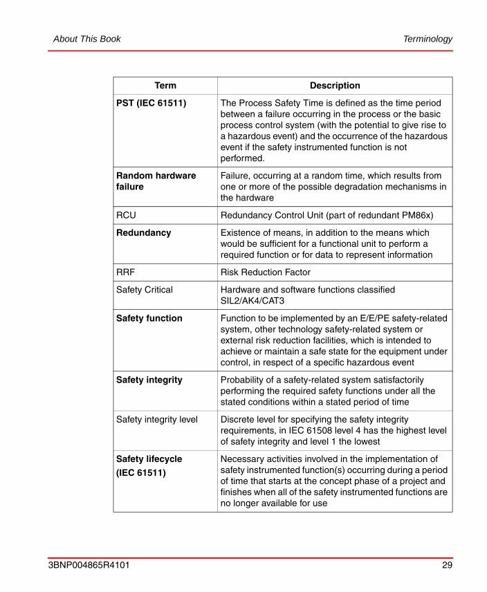
About This Book Terminology
PST (IEC 61511) The Process Safety Time is defined as the time period between a failure occurring in the process or the basic process control system (with the potential to give rise to a hazardous event) and the occurrence of the hazardous event if the safety instrumented function is not performed.
Random hardware failure
Failure, occurring at a random time, which results from one or more of the possible degradation mechanisms in the hardware
RCU Redundancy Control Unit (part of redundant PM86x)
Redundancy Existence of means, in addition to the means which would be sufficient for a functional unit to perform a required function or for data to represent information
RRF Risk Reduction Factor
Safety Critical Hardware and software functions classified SIL2/AK4/CAT3
Safety function Function to be implemented by an E/E/PE safety-related system, other technology safety-related system or external risk reduction facilities, which is intended to achieve or maintain a safe state for the equipment under control, in respect of a specific hazardous event
Safety integrity Probability of a safety-related system satisfactorily performing the required safety functions under all the stated conditions within a stated period of time
Safety integrity level Discrete level for specifying the safety integrity requirements, in IEC 61508 level 4 has the highest level of safety integrity and level 1 the lowest
Safety lifecycle
(IEC 61511)
Necessary activities involved in the implementation of safety instrumented function(s) occurring during a period of time that starts at the concept phase of a project and finishes when all of the safety instrumented functions are no longer available for use
Term Description
3BNP004865R4101 29

Terminology About This Book
SELV Safety Extra Low VoltageAn electrical system in which the voltage cannot exceed ELV (IEC 61131-2: 60V DC) under single fault conditions including earth faults in other circuits, (IEC 61140 ch. 3.26.1)
SFC Sequential Function Chart
SFC - Simultaneous Sequence
A SFC structure that allows several branches to execute simultaneously
SFC - Sequence Selection
A SFC structure that allows execution in only one of several alternative branches
SFF Safe Failure Fraction
SIL Safety Integrity Level according to IEC 61508
SIL2 Hardware and software functions certified according to SIL2/AK4/CAT3 to be used to control safety devices in a safety system
SIF Safety Instrumented Function (IEC 61511)
SIS Safety Instrumented System (IEC 61511)
SOE Sequence Of Event
ST Structured Text
Sub-system Part of a system (e.g. component as I/O module, I/O system or SW “package”)
Task A task is an execution control element that is capable of starting, on a periodic basis, the execution of a set of POUs (Programs, Function blocks, functions, etc.)
Validation(IEC 61511)
Activity of demonstrating that the SIF(s) and SIS(s) under consideration after installation meet in all respects the safety requirements specification.
Term Description
30 3BNP004865R4101

About This Book Terminology
Verification(IEC 61511)
Activity of demonstrating for each phase of the relevant safety life cycle by analysis and/or tests, that, for specific inputs, the output meet in all respects the objectives and requirements set for the specific phase.
VMT Virtual Machine Test, an automatically generated Application used to verify certain functions in the AC 800M HI
Watchdog Combination of diagnostics and an output device (e.g. a switch) for monitoring of the correct operation and taking action upon detection of an incorrect operation
Term Description
3BNP004865R4101 31

Applicable Specifications About This Book
Applicable SpecificationsThis product meets the following laws and standards.
Laws and Directives
General Safety Standards
73/23/EEC and amendments Low Voltage Equipment Directive
89/336/EEC and amendments
Electromagnetic Compatibility Directive
93/68/EEC and amendments CE marking Directive
98/37/EC Safety of Machinery (to the extent applicable)
94/9/EC – ATEX directive Electrical and mechanical equipment and protective systems, which may be used in potentially explosive atmospheres
IEC 61508 1999/2000
Functional safety of electrical/electronic/programmable electronic safety-related systems
DIN V 19250 (withdrawn)(1)
1994 Fundamental safety aspects to be considered for measurement and control equipment
DIN V VDE 0801 inc. A1 (withdrawn)(1)
1990 Principles for computers in safety-related systems
EN 954-1 1996 Safety of machinery - Safety-related parts of control systems
EN 61131-2 2003 Programmable controllers – equipment requirements and test
EN 60204-1 1997 Safety of machinery - Electrical equipment of machinesPart 1: General requirements (to the extent applicable)
EN 50081-2 1993 Generic standard – Emission for industrial environment
EN 61000-6-4 2001 Generic standard - Emission for industrial environments
EN 61000-6-2 2001 Generic standard - Immunity for industrial environments
32 3BNP004865R4101

About This Book Additional Approvals for Safety Compliance
Additional Approvals for Safety Compliance
Application Standards (to the extent applicable)
IEC 60079-0 Ed. 3.1 2004 Electrical apparatus for explosive gas atmospheresPart 0: General requirements
IEC 60079-15 Ed. 2.0 2001 Electrical Apparatus for Potentially Explosive AtmospheresType of Protection n
(1) The AC 800M HI is designed and certified in accordance with this withdrawn standard.
UL 508 2003 Industrial Control Equipment
UL 1998 2003 Standard for Software in Programmable Components
FM 7605 1999 Programmable Logic Control based Burner Management Systems
CSA 22.2.NO.142-M1987 2000 Process Control Equipment
EN 50178 1998 Electronic equipment for use in power installations
IEC 61511 2003 Functional safety - Safety Instrumented Systems for the process industry sector
IEC 61513(1) 2001 Nuclear power plants - Instrumentation and control for systems important to safety- General requirements for systems
ISA S84.01 1996 Application of safety instrumented systems for the process industries
ISO 10418 (API RP 14c) 1993 Petroleum and natural gas industries – offshore production platforms – Analysis, design, installation and testing of basic surface safety systems
DIN VDE 0116 1989 Electrical equipment for furnaces
prEN 50156-1 2003 Electrical equipment for furnaces
EN 298 1994 Automatic gas burner control systems for gas burners and gas burning appliances with or without fans
3BNP004865R4101 33

Application Standards (to the extent applicable) About This Book
EN 54-2 and -4 1997 Fire detection and fire alarm systems
NFPA 72 2002 National Fire Alarm Code
NFPA 85 2004 Combustion Systems Hazards Code(compilation of 8501 – 8506)
prENV 1954 1995 Internal and external fault behavior of safety-related electronic parts of gas appliances
(1) The system is not certified as a reactor protection system, but for general use in other applications in a nuclear power plant.
34 3BNP004865R4101

About This Book Related Product Documentation
Related Product DocumentationThe following is a listing of documentation related to the AC 800M HI.
Category Title Description
Hardware 800xA - Control and I/O, AC 800M Controller Hardware
Hardware and Operation
Control IT S800 I/O, General Information and Installation
User’s guide
Control IT S800 I/O, Modules and Termination Units
User’s guide
800xA - Safety, Reliability Calculations Data Sheets
Software 800xA - Control and I/O, Basic Control Software
Introduction and Configuration
800xA - Control and I/O, Extended Control Software
Analog and Binary Control
800xA - Control and I/O, Communication
Protocols and Design
800xA - Control and I/O, OPC Server for AC 800M
Installation and Configuration
800xA - Control and I/O, Addendum Product Data and Design
800xA - Control and I/O, Release Notes Control Software for AC 800M
3BNP004865R4101 35

Related Product Documentation About This Book
36 3BNP004865R4101

Section 1 Introduction
Safety PrinciplesIn most situations, safety is best achieved by an inherently safe process design whenever practicable. When this is not practicable, the residual risk must be identified and handled by one or more protective systems.The overall safety requirements of a process are identified by carrying out hazard and risk assessment, the identified safety requirements are allocated to safety functions and related protection systems (protection layers). Depending on the number of protection layers identified, and the risk reduction they provide, the need for a Safety Instrumented System (SIS) may arise. For each identified safety function the Safety Integrity Level (SIL) must be identified.
The AC 800M HI is certified to handle safety functions with SIL2 requirement.
Important characteristics of the SIS are the response time during normal operation; Demand Response Time (DRT), and the response time during internal faults; Fault Detection and Reaction Time (FDRT). These characteristics of the SIS relates to the Process Safety Time (PST) of the process to be controlled. For definitions of terms and abbreviations like DRT, FDRT and PST, see Terminology on page 25.
As the initiator and actuator response time varies for various devices, the SIS shall be configured to guarantee a logic solver FDRT (see Figure 1 below) to meet the process requirements according to the applicable industrial standards.
3BNP004865R4101 37

Safety Principles Section 1 Introduction
Figure 1. Process Safety Time (PST)
Note to Figure 1:
When configuring the FDRT for the logic solver, the initiator response time does not need to be considered, hence the time required to bring the process to safe state upon an internal fault in the AC 800M HI is only dependent of the FDRT and the actuator response time.
FDRT < PST - Actuator Response Time
The AC 800M HI supports an FDRT down to 1 second.
Initiator response time
Logic solver FDRTFault Detection and
Reaction Time
Actuator response time
Undesirable event Safety function response time Safe action performed
Process Safety Time, PST
38 3BNP004865R4101

Section 1 Introduction Safety Principles
The DRT of the logic solver, is the time for processing an event in the input sub-system, scan the input sub-system, execute the functional logic, update the output sub-system and processing the desired action in the output sub-system. (Initiator and actuator response times are not included).
Figure 2. Demand Response Time
The DRT of the AC 800M HI is mainly dependent on the size and the execution cycle of the application(s) and the number of I/O modules used. For a small application (with no complex calculations) and with a limited set of I/O modules (e.g. one cluster), a DRT down to 40 ms is possible.
Initiator response
time
Logic solver functional logic execution time
Actuator response
time
Process event
Logic Solver Demand Response Time Desired action
performed
Input sub-system
response time
Output sub-system
response time
New input signal
available
New control signal
available
3BNP004865R4101 39

Product Overview Section 1 Introduction
Product OverviewThis section contains a brief overview of the main characteristics and intended use of the AC 800M HI.
The AC 800M HI is certified to comply with the requirements of:
• Requirement Class AK 1 - 4 according to DIN V 19250/DIN V VDE 0801
• Safety Integrity Level 1 - 2 according to IEC 61508
• Category 1 - 3 according to EN 954-1.
Additionally, a set of other relevant safety/application standards are supported by the AC 800M HI, see Applicable Specifications on page 32.
The AC 800M HI is realized as a 1oo1D system, by combining the PM865 processor module, with the SM810. The SM810 performs diagnostics and monitoring of the application execution and I/O scanning in the PM865.
The S800 I/O High Integrity modules (AI880/AI880A, DI880 and DO880) are prepared and certified for use in SIL1-3 / AK 1-6 / CAT 1-4 safety functions as single modules. This is achieved by using an internal diverse redundant structure with diverse execution and mutual supervision.
The AC 800M HI offers a certified control environment that can host a combination of non-SIL classified BPCS functions and SIL1-2 classified safety functions in the same controller. In order to enable this, a SIL classification of user applications is introduced.All functions/types in standard libraries usable in SIL 2 classified applications are marked SIL2.
Communication modules and protocols that are not certified for safety critical use as well as non certified I/O modules, are possible to use in SIL classified applications for non safety critical functions, e.g. process feedback, status indications, etc.
External influence to the AC 800M HI is controlled by the Access Management package that contains functionality to allow human interactions from engineering tools or operator stations in a safe and pre-configured way.
40 3BNP004865R4101

Section 1 Introduction Product Overview
The general topology, in which the AC 800M HI is totally integrated, is shown in Figure 3.
Figure 3. System topology
Control Network Redundant TCP/IP
800xA Operator Workplace+ControlBuilder M Professional
Plant network (TCP/IP)
800xA Operator Workplace
AC 800M Controller with S800 I/O via optical bus
800xA Operator Workplace
AC 800M HI Controller with S800 I/O via optical bus
3BNP004865R4101 41

Mode of Operation Section 1 Introduction
Mode of Operation
The Mode of Operation is the way in which the Safety Related System will be used with respect to frequency of demands upon it. Two modes of operation are defined in IEC 61508:
Low Demand Mode: where the frequency of demands for operation made on a safety related-system is no greater than one per year and no greater than twice the proof-test frequency;
High Demand or Continuous Mode: where the frequency of demands for operation made on a safety-related system is greater than one per year or greater than twice the proof-test frequency.
AC 800M HI can operate in both Low Demand and High Demand applications, provided the safe state is defined as stop/de-energize.
The AC 800M HI can be configured with a “fault detection and reaction time” as low as one second.
Redundancy
AC 800M HI does not require any redundancy for safety integrity reasons. However, the controller and I/O system can be designed for any optimization of system availability (system uptime) by individually being configured with redundant input modules, redundant CPU/communication modules and/or redundant output modules.
42 3BNP004865R4101

Section 1 Introduction Prerequisites and Requirements
Prerequisites and Requirements
Equipment Requirements
The following equipment is required in order to program, configure, install, verify and operate the AC 800M HI controller.
• The Control Builder M Professional must be used for engineering and application download. It can also be used for monitoring the application during operation.
• The 800xA Operator Workplace is available as operator interface. By means of the “Confirmed Online Write” function, safe write to application variables is allowed (configurable) during operation of the plant.
Information Requirements
Required user documentation is listed in the chapter Related Product Documentation on page 35.
Special attention must be paid to the 800xA - Control and I/O, Release Notes for the actual version of the AC 800M HI. This document contains information on compatibility questions, any known failures in the system, and other “last minute” information.
The certified versions of hardware and software modules are listed in the valid version of the annex to the TÜV certification report.
Restrictions for Use of the System
Environmental restrictions and considerations are described in chapter Site Planning on page 67.
The AC 800M HI is suitable for unsupervised operation, i.e. it can operate without Control Builder M Professional or 800xA Operator Workplace connected.
Requirements and instructions marked with the Warning symbol in this manual must be adhered to for the system to remain in compliance with the requirements of the certification.
3BNP004865R4101 43

Restrictions for Use of the System Section 1 Introduction
44 3BNP004865R4101

Section 2 Management of Functional Safety
This section provides guidelines and input to the management activities that are necessary to ensure that the functional safety objectives are met during all phases of the lifecycle of a safety system.
In addition to guidelines given here, the relevant application standards should be considered and fulfilled.
The management activities with respect to Functional Safety shall be identified, documented and planned as part of an overall Quality and Safety Plan.
The Policy and Strategy for achieving safety shall be identified and defined together with the means for evaluating its achievement and shall be communicated within the organization.The policy and strategy shall contain:
• SIL Statement
• Project category statement (size, scope, complexity, management)
• Safety Verification strategy
• Safety Validation strategy
• Safety Assessment strategy
• Handling of non-certified components
A Safety Management System shall be in place; this could be integrated with the Basic Quality Management System of the organization.
3BNP004865R4101 45

Organization and Resources Section 2 Management of Functional Safety
Organization and ResourcesThe organizational structure with Roles and Responsibilities shall be defined and clearly communicated and understood by all involved parties. For each role, unambiguous accountabilities shall be defined.
Persons, departments, organizations and other units shall be competent to carry out the activities for which they are accountable.
A qualification process shall be established in order to specifically qualify persons, departments, organizations and other units that are involved during the lifecycle of the safety system.
As the AC 800M HI can comprise both unclassified process control applications and SIL classified applications in the same controller, the organization and procedures must reflect the different requirements that apply.
Safety PlanningSafety Planning shall take place to define required activities, along with the persons, departments, organizations or other units responsible to carry out these activities.
Safety Planning shall include those activities that are specifically addressing Management of Functional Safety.
Implementation and Monitoring• Procedures shall be implemented to ensure prompt follow-up and satisfactory
resolution of qualified recommendations arising from:
– Hazard analysis and Risk Assessment
– Assessment and Auditing activities
– Verification activities
– Validation activities
– Post-incident and Post-accident activities
46 3BNP004865R4101

Section 2 Management of Functional Safety Assessment, Auditing and Revisions
• Procedures shall be implemented for monitoring the safety performance of the system during the operation phase. Performance shall be verified against the requirements given in the Safety Requirement Specification.Emphasis shall be put on:
– Component failure rates
– Demand rates (compared with the initial assumptions made)
– Systematic failures (including operator and maintenance aspects)
• Procedures shall be implemented to verify the adequacy of the quality management system of all sub suppliers.
Assessment, Auditing and RevisionsA procedure shall be defined and executed for a Functional Safety Assessment (FSA), in such a way that a judgment can be made as to the functional safety and safety integrity achieved by the Safety Instrumented System.
Functional Safety Assessment aims to evaluate whether necessary provisions are made during the assessed lifecycle to ensure that required Functional Safety is or will be achieved. The procedure shall require an assessment team to be appointed that includes the technical, application and operations expertise needed for the particular installation. The procedure shall cover:
• Assessment Team organization and independency
• FSA Planning (Scope)
• FSA Minimum requirements (Scope)
• Development and production tools
• Recording and Reporting including specification of document templates
• Requirements for Follow-up
Functional Safety Assessment Team
The organization of the FSA Team and the criteria for selection of team members shall be well defined. To increase objectivity, the FSA team shall have a defined
3BNP004865R4101 47

Assessment, Auditing and Revisions Section 2 Management of Functional Safety
level of independency with respect to the actual project team. At least the FSA team leader shall be from an independent organization. Depending on the organization of the company and the internal skills within the company, the company may use their own resources to meet requirements for an independent organization.
Functional Safety Assessment Planning
The stages in the safety lifecycle at which the Functional Safety Assessment activities are to be carried out shall be identified during safety planning.The number, size and scope of FSA should be defined upon specific circumstances that shall be defined. The circumstances and the method to select FSA scope shall be defined.
Functional Safety Assessment - minimum requirements
One Functional Safety Assessment, as a minimum, shall be carried out to make sure that the hazards arising from the process and its associated equipment are properly controlled. It shall be carried out prior to the startup of the process and shall confirm that:
• Hazard and risk assessment has been carried out, and recommendations are implemented and resolved
• Project design procedures are properly implemented
• The SIS is in accordance with the safety requirement specification
• The operation, maintenance and emergency procedures to the SIS are in place
• The validation planning is appropriate and validation activities are completed
• The training activities of maintenance and operating personnel are completed
Functional Safety Assessment of Development and Production Tools.
Where development and production tools are used for any safety life-cycle activity, they shall themselves be subject to a Functional Safety Assessment.
48 3BNP004865R4101

Section 2 Management of Functional Safety Auditing and Revision Procedures
Functional Safety Assessment Reporting
The result of the Functional Safety Assessment shall be available together with any recommendation coming from this assessment.
FSA reporting shall be clarified for the actual phase. Responsibilities and Accountabilities for both the content of the report as well as for responses to the report shall be defined. A standardized FSA report template shall be defined that include a defined distribution.
Auditing and Revision Procedures
Audits, revisions or inspections aim to check whether required provisions (procedures) for achievement of functional safety are implemented and are working properly.
Procedures shall be defined and executed for auditing compliance with the following requirements:
• Requirements for categories of Safety Audits
• Requirements for frequency of Safety Audits
• Requirements for qualifications of Audit personnel
• Requirements for Audit planning including Audit strategy
• Requirements for recording and reporting
• Requirements for follow-up
Auditing and Revision, Procedures for Management of Modifications
Management of Modifications is essential and sensitive to Functional Safety – especially over time. Audits and revisions of procedures for management of modifications are therefore vital.Although this requirement mostly is interpreted to specifically address the operation phase, the other phases should also be covered.
3BNP004865R4101 49
Configuration Management Section 2 Management of Functional Safety
Configuration ManagementConfiguration Management aims to manage and maintain traceability of devices through the lifecycle of the SIS.
The user of the system shall establish a practice to maintain an overview of SW and HW versions of the installed equipment, as well as versions of application SW and libraries.
If the system is configured as a combined BPCS and SIS, the configuration management procedures must identify the different requirements for handling subsystems of different SIL.
Procedures must be established for preventing unauthorized items from entering service.
50 3BNP004865R4101

Section 3 Safety Lifecycle Activities
The content of this section is organized in accordance with the safety lifecycle process as defined in IEC 61511. For each phase of the lifecycle, guidelines, instructions and requirements related to the use of the AC 800M HI are given.
Adherence to these instructions is necessary to meet the requirements of the general safety standards listed in Applicable Specifications on page 32.
Application specific standards may contain additional requirements to configuration and application design, such requirements are not reflected in this manual.
For detailed operation instructions, the reader is referenced to Related Product Documentation on page 35.
Process Hazard and Risk AssessmentProcess Hazard and Risk Assessment is performed to determine the hazards and associated risks of the process to be controlled. The need for risk reduction, and required safety functions shall be identified.
The results from such analysis are necessary input for the subsequent phases of the engineering and operation of a SIS.
Requirements in the application specific standards listed in the chapter Applicable Specifications on page 32 and other relevant and valid application standards must be adhered to (e.g.EN 54, EN298).
3BNP004865R4101 51

Allocation of Safety Functions Section 3 Safety Lifecycle Activities
A hazard and risk assessment shall be carried out on the process and its associated equipment, and shall result in:
• Undesirable event specification, description and causes, (including human errors)
• Consequences and likelihood of undesirable events
• Consideration of conditions (process phases, process upset, shutdowns)
• Determination of requirements for additional risk reduction
• Assumptions made during analysis (demand rates, failure rates, operational constraints or human intervention)
• Description of measures taken to reduce hazards and risk
• Allocation of safety functions to layers of protection
• Identification of safety instrumented functions
It may be necessary to perform Hazard and Risk assessment at several stages of the project.
The hazard and risk assessment shall be recorded in such a way that relationship between the above items is clear and traceable.
The extent of risk reduction necessary will vary depending on application, legal requirements and on an evaluation of the cost-value achievement.
Allocation of Safety FunctionsIn order to determine the need for a SIS and its SIL, it is necessary to consider what other protection layers exist and their level of protection.
The Allocation of Safety Functions is necessary input for the subsequent phases of engineering a SIS.
The Risk Reduction Factor shall be determined for the different layers of protection. The Allocation process shall also include allocation of Safety Instrumented Functions to individual SIS and subsystems.
From the allocation process the Risk Reduction Factor (RRF) requirement will be derived for the Safety Instrumented Functions (SIF). The SIL for the Safety
52 3BNP004865R4101

Section 3 Safety Lifecycle Activities Safety Requirement Specifications
Instrumented Functions shall be set taking into account the required RRF.The Safety Integrity Level requirement is related only to the complete Safety Instrumented Function that is defined and allocated for the actual identified hazard. The distinction between Risk and Safety Integrity should be noted. Risk is a measure of the frequency and consequence of a specified hazardous event. Safety Integrity is a measure of the likelihood that the SIF (or other protection functions) will provide the specified safety function when demanded.
Demand Mode of Operation
For safety-instrumented functions where the demand rate is specified to be once per year or less, Table 3 in part 1 of IEC61511 will be used for defining the safety integrity level.
Continuous Mode of Operation.
For safety-instrumented functions where the demand rate is specified to be more than once per year or greater than twice the proof test frequency, Table 4 in part 1 of IEC61511 will be used for defining the safety integrity level.
Safety Requirement SpecificationsThe Safety Requirement Specification is the main input for the design of the SIS. The requirements may be collected in one single document or a collection of several documents and drawings. The requirements should be expressed in such a way that they are clear, precise, verifiable, maintainable and feasible with respect to all phases of the lifecycle.
Normally the Safety Requirement Specification will cover the following items:
• A description of all the safety instrumented functions.
• Common cause failures shall be identified and taken into account.
• Safe state shall be defined for each identified SIF.
• Any individually safe states which, when occurring concurrently, create a separate hazard shall be identified.
3BNP004865R4101 53

Safety Requirement Specifications Section 3 Safety Lifecycle Activities
• Source of demand and demand rate for the SIF shall be identified.
• Proof test interval for each SIF.
• The response time for the SIS to bring the process to a safe state.
• The safety integrity level and the mode of operation for each SIF.
• A description of SIS process measurements and their trip points.
• A description of SIS process output actions and the criteria for successful operation, for example, requirements for tight shut-off valves.
• The functional relationship between process inputs and outputs, including logic, mathematical functions and any required permissive.
• Requirements for manual shutdown when applicable.
• Requirements related to energize or de-energize to trip.
• Requirements for resetting the SIS after shutdown.
• The maximum spurious trip rate shall be specified.
• Failure modes and desired response of the Safety Instrumented System.
• Any specific requirements related to starting up and restarting the SIS.
• All interfaces between the SIS and any other system as well as operators.
• The modes of operation of the plant and identification of the safety instrumented functions required to operate within each mode.
• The application software safety requirements as listed in Application Safety Requirement Specification on page 69.
• Requirements for overrides, inhibits and bypasses.
• Any action necessary to achieve or maintain a safe state in the event of fault(s) being detected in the SIS, taking account for all relevant human factors.
• The mean time to repair that is feasible for the SIS.
• Potential dangerous combinations of output states of the SIS.
• The extremes of all environmental conditions likely to be encountered by the SIS.
54 3BNP004865R4101

Section 3 Safety Lifecycle Activities Safety Requirement Specifications
• Normal and Abnormal modes of Plant operation.
• Requirements for any SIF necessary to survive a major accident event.
3BNP004865R4101 55

System Design and Engineering Section 3 Safety Lifecycle Activities
System Design and Engineering
System Structure Selection
The AC 800M HI, including its I/O system can be designed for any optimization of system availability (system uptime) by individually being configured with redundant input modules, redundant CPU/communication modules and/or redundant output modules.
If the safety functions of the plant require more than one AC 800M HI, for capacity or geographical reasons, they can interchange safety critical data by means of the certified peer-to-peer communication. For more information, see Communication Interfaces on page 64.
Figure 4 and Figure 5 shows example of single and redundant configurations, the various modules and redundancy options are described below.
The AC 800M HI does not require any redundancy for safety integrity reasons
56 3BNP004865R4101

Section 3 Safety Lifecycle Activities System Structure Selection
Figure 4. Single AC 800M HI system
Non-redundant optical Modulebus
1-12 local non-redundant I/O modules, connected to the built-in electrical Modulebus
I/O modules on redundant bus
To next cluster modem
Cluster modem for optical to redundant electrical Modulebus conversion
Redundant pair
Field and field power connection
SM810
Redundant Control network
Optional communication module
PM865
3BNP004865R4101 57

System Structure Selection Section 3 Safety Lifecycle Activities
Figure 5. Redundant AC 800M HI system
Optical Modulebuses
I/O modules on redundant bus
To next cluster modems
Cluster modems, optical to redundant electrical Modulebus conversion
Redundant pair
Field and field power connection
Primary
Hot stand-by
SM810 BC810
Redundant Control network
RCU-link cable
CEX-Bus inter-connection cable
Optional communication module
PM865
58 3BNP004865R4101

Section 3 Safety Lifecycle Activities System Structure Selection
Redundancy
The redundancy scheme implemented enables increased availability and fault tolerance on:
• Controller
• Communication expansion bus (CEX-Bus)
• Communications modules on the CEX-Bus
• Optical ModuleBus (when controller redundancy is used)
• Optical Cluster Modems (when controller redundancy is used)
• Electrical ModuleBus (not the local built-in electrical ModuleBus)
• I/O modules
• Power Supply
Below is a summary of the possibilities available for each component and sub-system.
Redundant AC 800M HI Controller (PM865/SM810)
By adding a secondary AC 800M HI processor unit (PM865 and SM810) in hot stand-by mode, full redundancy is achieved on controller level.
After a power-on, the PM865 with the “upper-end” of the redundancy cable undertake the primary role and the other becomes the stand-by. The proven redundancy concept ensures that the stand-by PM865 is cyclically updated and kept “synchronized” by the primary PM865, over the Redundancy Control Unit link (RCU-link).This concept guarantees a takeover time of typically 4-6 ms (maximum 10 ms).
The SM810 is not configured to operate in primary or stand-by mode. Instead both modules are actively performing the same tasks. In a configuration with two SM810s both modules are continuously updated by the primary PM865, but only one of the SM810s is used for input data (read from). This concept enables almost instant takeover, upon internal fault detection in one SM810.
A Processor Module fail-over does NOT imply a change of SM810 or communication units connected via the CEX-Bus. Also the primary I/O modules are
3BNP004865R4101 59

System Structure Selection Section 3 Safety Lifecycle Activities
kept (communication is switched to the other set of cluster modems) thus preventing e.g. leaps in analog input signals.
Redundant Optical ModuleBus
In redundant AC 800M HI systems, the redundant optical Cluster Modems enables redundant ModuleBus communication. Each PM865 is connected to one Cluster Modem. If one of the optical buses fails, communication is maintained by switching to the other AC 800M HI processor unit, this does not imply a switch over to redundant I/O modules.
Redundant Electrical ModuleBus
This is achieved by using optical Cluster Modems and Module Termination Units (MTUs) designed for housing redundant I/O modules. To take advantage of redundant electrical ModuleBus, one also needs to use two I/O modules, because an I/O module is only connected to one of the electrical ModuleBuses.
Failures related to an electrical ModuleBus causes the Cluster Modem(s) to switch to the second electrical ModuleBus. As a consequence, primary I/O modules are changed.
Redundant High Integrity I/O Modules
Requires use of optical Cluster Modems and MTUs intended for redundant I/O modules. The AC 800M HI treats input and output modules differently:
Input Modules
The controller assigns one of the input modules in a redundant pair as primary and the other one as stand-by. The input values and their status are read from the primary module and will be treated as valid until the module reports channel- or module fault, or until the communication is interrupted.
The local built-in electrical ModuleBus cannot be used in configurations with redundant AC 800M HI.
Redundant AC 800M HI processor units, require redundant optical Cluster Modems.
60 3BNP004865R4101

Section 3 Safety Lifecycle Activities Process Interface Selection
The stand-by module in the pair is accessed from time to time (typically every 10th scan of the primary) to determine the status of the channels, the module itself and the electrical ModuleBus.
Upon a channel fault on the primary module, the controller switches to the stand-by module and assigns it as the primary; the previous primary module will be stopped.
Output Modules
Digital outputs in a redundant pair are both active, both modules are always accessed one after the other in sequence. Both modules are therefore given the same values and both modules controls the outputs (and the field), which enables uninterrupted control of the outputs in case of a channel, module or electrical ModuleBus fault.
Redundant CEX-Buses
The BC810 offers a way to section the CEX-Bus into two independent segments. This improves the availability in systems with redundant communication interfaces.
Redundant Power Supply
AC 800M HI systems can be equipped with redundant supplies for both system power and field power.
For details on configuration possibilities, refer to the user manuals 800xA - Control and I/O, AC 800M Controller Hardware and Control IT S800 I/O, General Information and Installation.
Process Interface Selection
Allocation of I/O Modules
The S800 I/O system can be connected via the direct electrical ModuleBus (only available for single I/O modules), or via the optical ModuleBus and cluster modems.
In redundant AC 800M HI systems, the CEX-Bus shall always be connected via the CEX-Bus Interconnection Unit, BC810.
3BNP004865R4101 61

Process Interface Selection Section 3 Safety Lifecycle Activities
Each I/O cluster can contain a maximum of 12 single I/O modules, alternatively 6 redundant modules, hence limiting the total number of modules to 12.A maximum of 8 clusters (including the local electrical) can be connected to one AC 800M HI.
Certified and non-certified I/O modules can be connected to the same cluster.
For information on the S800 I/O system, refer to the user manuals Control IT S800 I/O, General Information and Installation and Control IT S800 I/O, Modules and Termination Units.
The following I/O modules are certified for safety critical use in AC 800M HI:
– AI880/AI880A High Integrity Analog Input Module
– DI880 High Integrity Digital Input Module
– DO880 High Integrity Digital Output Module
See relevant chapters below for a summary of the safety related characteristics of each module.
AI880/AI880A High Integrity Analog Input Module
The module is certified SIL3/AK6/CAT4 for the input range 4-20 mA. The range between 0-4 mA can be utilized for diagnostic purposes.The certification is valid in both single and redundant configurations.
The AI880A module supports routing of HART signals to the connected transmitters. It is important to be aware that the HART protocol supports functions that can change the behavior of the connected transmitters, like calibration and simulation.If this functionality is to be used during operation of the plant, the utilization must be supported by organizational procedures to maintain the safety integrity of the
For safety critical functions, only certified I/O modules shall be used. If non- certified I/O modules are connected to a SIL Application a warning is given, but download of the Application is allowed upon engineer’s approval.
62 3BNP004865R4101

Section 3 Safety Lifecycle Activities Process Interface Selection
installation. The AI880A module can be configured to restrict the HART routing in three levels (full, read only, disabled).
DI880 High Integrity Digital Input Module
The module is certified SIL3/AK6/CAT4 for normally closed input loops (i.e. open for alarm).The certification is valid in both single and redundant configurations.
The DI880 module support Sequence Of Event (SOE) recording with a resolution of 1 ms, the accuracy of the recording is 1.3 ms.
DO880 High Integrity Digital Output Module
The module is certified SIL3/AK6/CAT4 for NE and ND outputs.For both output types, safe state is defined as de-energize; i.e. upon fatal errors, (as CPU, power failure, loss of contact with controller), all outputs will be de-energized.
The HART functionality of AI880A is approved to be interference free, for non safety critical use.
The use of HART routing of AI880A during operation of the plant, must be restricted by configuration or by operational procedures.
If the input loops of AI880/AI880A is externally powered, or another risk of applying 24V to the signal line is present, the loop should be equipped with a fuse (rated <= 0.1A) in the signal line to avoid possible overheating of the shunt stick during fault situations.
The sequence of event functionality of DI880 is certified interference free, for non safety critical use.
If an input loop of DI880 is externally powered, the loop must be equipped with a current limiting device in the signal line. The current must be limited to 200 mA.
3BNP004865R4101 63

Communication Interfaces Section 3 Safety Lifecycle Activities
The certification is valid in both single and redundant configurations.
Allocation of I/O Channels
If a safety function is equipped with redundant instrumentation, it is recommended for availability reasons to distribute the signals to different I/O modules wherever practical.
Communication Interfaces
The AC 800M HI comprises peer-to-peer communication via the control network; the communication is certified for safety critical use. Actually this function is a “peer-to-multiple-peer” communication, i.e. data made available for communication in one controller, can be read from multiple controllers.This peer-to-peer communication can be established by using the MMS control modules designed for this purpose, for more details, see Software Architecture on page 71.
Other available communication interfaces are certified interference free, i.e. they can be used in the AC 800M HI and the data communicated on them can be used in both SIL and non-SIL Applications, but only for non safety critical functions.
For information on available communication interfaces refer to the user manual 800xA - Control and I/O, Communication.
Power Supply
For information on available power solutions and recommended configurations, please refer to the user manuals 800xA - Control and I/O, AC 800M Controller Hardware.
Older versions of DO880 (PR:C and older) are vulnerable to reverse polarity on the power terminals, and will be damaged upon exposure to such conditions.
The communication interfaces CI851, CI852, CI858, CI860 and CI862 are not available in the AC 800M HI controller.
The AC 800M HI and the connected S800 I/O system (including field power) must be supplied from a SELV or PELV power supply connected through the power voter SS823.
64 3BNP004865R4101

Section 3 Safety Lifecycle Activities Operator Interface
Operator Interface
Physical I/O for Operator Interaction
The SM810 module in the AC 800M HI Processor Unit provides two digital inputs and two digital outputs intended for connection to an operator’s panel.
• Digital Inputs
– Reset all Forces (I1)
– Access Enable (I2)
• Digital Outputs
– Any Force Active (O1)
– System Alarm (O2)
For connection details, refer to the user manual 800xA - Control and I/O, AC 800M Controller Hardware.
The Access Enable input needs to be active to allow download to the AC 800M HI. Also write operations to variables configured as “confirm and access enable” are restricted by this input.1 This input should be connected to a key switch in the operator’s panel.The function block ForcedSignals and Control Module ForcedSignalsM provides
Older versions of AI880 (PR:B), DI880 (PR:B) and DO880 (PR:C), including field power, must be supplied from the SD821, SD822 or SD823 power supplies connected through the power voter SS823. (This restriction is not valid for AI880A and newer versions of DI880 and DO880).
If any field device connected to the AC 800M HI is externally powered, the device must be supplied from a SELV or PELV power supply connected through the power voter SS823.Exception: When externally powered transmitters are connected to the analog input module AI880/AI880A via a fuse rated 60V/<= 0.1A, the SS823 can be omitted. This is valid for loops up to SIL2.
1. Only valid for variables in a SIL marked Application.
3BNP004865R4101 65

Operator Interface Section 3 Safety Lifecycle Activities
the status of the Access Enable input for use in Application programs and for presentation on 800xA Operator Workplace and Control Builder M Professional.
The Reset All Forces input provides a possibility to reset the force property of all forced I/O channels connected to SIL marked Applications.
For a more detailed description of this functionality, see Access Management Settings on page 93.
The digital outputs could be used for activating external visual or audible indications.The Any Force Active output is activated if any I/O variable in a SIL marked Application is forced. This output should be used for indication to operators.
For information about configuring the System Alarm output, see Controller Settings and Restrictions on page 81.
800xA Operator Workplace
For SIL Applications, the AC 800M HI provides protection against unauthorized writing from other computers on the control network. This protection layer is named “Confirmed Write” and consists of a special communication protocol securing that correct operation is performed on correct object.Any attempt to write to variables and parameters belonging to a SIL Application will be stopped by the AC 800M HI if the “Confirmed Write” protocol is not used.
800xA Operator Workplace supports the “Confirmed Write” protocol and can be used for both viewing and modifying variables in AC 800M HI. The possibility to modify variables in SIL Applications are also restricted by the “SIL Access Control”, see Access Management Settings on page 93.
The Reset All Forces input is acting on the local controller only; a plant wide reset facility can be established using the peer-to-peer communication.
If used, the Reset all Forces input must be connected to an impulse type panel button.
66 3BNP004865R4101

Section 3 Safety Lifecycle Activities Maintenance/Engineering Interface
Maintenance/Engineering Interface
The instructions and procedures given in this manual require the use of Control Builder M Professional for engineering and application download. Various front-end applications like Function Designer, Reuse assistant or Bulk data manager can be utilized, but the Control Builder M Professional must be used as the interface to the AC 800M HI.The IEC 61131-3 application code must be compiled before it is downloaded to the AC 800M HI. Regardless of which editors or programming tools that are utilized to produce the application source code, the compilation and download must be done with the Control Builder M Professional.
All data is stored in the Aspect directory of the 800xA system. The engineering environment supports multiple users.
Site Planning
Guidelines for planning the installation of an AC 800M HI system are given in the user manuals 800xA - Control and I/O, AC 800M Controller Hardware and Control IT S800 I/O, General Information and Installation.These manuals are giving guidelines and requirements for environmental conditions, cables, power supply and grounding.
Enclosures
The 800xA - Safety modules are of protection class IP20 and each module is individually CE-marked. In office environment, they can be used without any additional enclosure. In normal industrial environment it is necessary to provide a higher protection class than IP20 by adding a suitable enclosure.
If the use of one of the mentioned editors violates any of the safety restrictions described in this manual, it will not be possible to download the application to the AC 800M HI.
If a multi user engineering environment is established, procedures must be in place to avoid that two users are doing modifications to the same data entity simultaneously.
3BNP004865R4101 67

Site Planning Section 3 Safety Lifecycle Activities
For more information, refer to the user manual 800xA - Control and I/O, AC 800M Controller Hardware.
68 3BNP004865R4101

Section 3 Safety Lifecycle Activities Application Software
Application SoftwareThe term software in this sub-section refers to application software developed in one of the languages defined by IEC 61131-3 or in control modules, including controller and I/O configurations. For more information on available languages see Programming Languages and Libraries on page 77.
Safety Lifecycle
Activities must be defined and planned for design, development and test/verification of the application software until it is integrated with the hardware and ready for installation and commissioning as described in Installation and Commissioning on page 101.
The following chapters give guidelines and input to these activities when working with the AC 800M HI.
• Software Architecture on page 71
• Programming Languages and Libraries on page 77
• Control Builder M Professional - Settings and Restrictions on page 79
• Controller Settings and Restrictions on page 81
• I/O Module Settings on page 88
• Access Management Settings on page 93
• Configuration Management on page 96
• Software Module Testing on page 98
• Software Integration Testing on page 98
• Integration of Application Software with the System Hardware on page 99
• System Integration Testing on page 99
• Modification Testing on page 99
Application Safety Requirement Specification
The Application Safety Requirement Specification is the main input for the design of the application software. This specification normally contains more detailed and
3BNP004865R4101 69

Safety Validation Planning Section 3 Safety Lifecycle Activities
specific requirements to the software development than present in the SIS Safety Requirement Specification (see Safety Requirement Specifications on page 53). The Application Safety Requirement Specification may be included in the SIS Safety Requirement Specification.
The requirements should be expressed in such a way that they are clear, precise, verifiable, maintainable and feasible with respect to all phases of the lifecycle.
Normally the Application Safety Requirement Specification will cover the following items:
• Safety functions to be supported
• Capacity and response time
• Interfaces to operators and other equipment
• Modes of operation of the process
• Actions on faulty process inputs
• Testing of external devices (sensors, actuators and final elements)
• Software self testing (e.g. watch dogs and range checking)
• Periodic testing of the SIF during operation
Safety Validation Planning
The Safety Validation of the application software must be planned in accordance with the descriptions in Safety Validation on page 106.
Application Design and Development
General
This chapter provides guidelines and requirements on what to consider and which configuration settings to perform during application design, programming and handling of the AC 800M HI.For instructions on how to perform the different tasks, please refer to the user manuals 800xA - Control and I/O, Basic Control Software and 800xA - Control and I/O, Extended Control Software.
70 3BNP004865R4101

Section 3 Safety Lifecycle Activities Application Design and Development
Software Architecture
Applications
The term Application is used in Control Builder M Professional to denote a “container” for executable programs and variables that are grouped together.
The control software for a system can be divided into Applications based on functionality, process characteristics, geographical conditions or other plant specific criteria.
Rules and guidelines on how to utilize the features of AC 800M HI and the Control Builder M Professional to achieve a good design of the application software is described in the user manual 800xA - Control and I/O, Basic Control Software.
When engineering the AC 800M HI controller, two Applications and one Library are automatically created.
• “CTA” is the Compiler Test Application, used to make sure that the IEC 61131-3 compiler works properly (this application is not downloaded to the controller).
• “VMTxx...” is a diagnostics Application used to verify certain functions of the AC 800M HI. The name of this Application is made up of the prefix VMT_ and the name of the controller.
• VMTLib is the Virtual Machine Test library, containing types used when running the VMT Application.
The CTA and VMT Applications and Library are for diagnostic purpose. They are automatically created and included; hence should not be deleted or altered in any way. However, if manually changed, they are automatically restored before download.
3BNP004865R4101 71

Application Design and Development Section 3 Safety Lifecycle Activities
Combined SIL and non-SIL Classified Applications
The AC 800M HI allows SIL classified functions (e.g. SIS) and non-SIL classified functions (like BPCS) to be programmed and executed in the same controller. In such configurations the SIL and non-SIL functions must be programmed in different Applications.In Control Builder M Professional, the SIL is selected for each Application. The selection of SIL automatically activates the relevant restrictions and limitations that apply.
Communication Between Applications
A range of function blocks are available for interchanging data between two SIL marked applications, or between SIL marked and non-SIL marked applications. The data communicated by means of this function blocks can be used for non safety critical functions in the SIL marked application.
By means of the Control Modules MMSDef2DwordM and MMSRead2DwordM, a certified link between two SIL marked applications can be established for exchanging safety critical data. By using this link, one SIL marked application is able to read data from other applications, both SIL marked and non-SIL marked.
For all safety critical Applications, correct SIL must be selected in Control Builder M Professional.
A SIL marked Application can only be connected to a SIL marked task, and a non-SIL marked Application can only be connected to a non-SIL marked task.
The function block types MMSConnect, MMSDef4Bool1, MMSDef4BoolIO1, MMSDef4Dint1, MMSDef4DintIO1, MMSDef4Real1, MMSDef4RealIO1, MMSRead4Bool1, MMSRead4BoolIO1, MMSRead4Dint1, MMSRead4DintIO, MMSRead4Real1 and MMSRead4RealIO1, for communication between controllers, are allowed used in SIL classified applications, but the data communicated cannot be used for safety critical functions.
72 3BNP004865R4101

Section 3 Safety Lifecycle Activities Application Design and Development
Data communicated in this way between two SIL marked applications, is allowed used for safety critical functions.
FDRT of the communication subsystem is a function of the parameter Faultcount of the control module, and the cycle time of its execution.
FDRT =2* FaultCount * Cycle TimeClient +Cycle TimeServer
Example: Using FaultCount = 3, Cycle TimeClient = 500ms and Cycle TimeServer = 500ms givesFDRT for the communication = 2*3*0.5s + 0.5s= 3.5s.
The parameter FaultCount has two different, but related fields of application in the MMS communication modules. In addition to the fault count function described above, it is used as a scaling factor for defining a time delay window for acceptance of messages.
Example: Using Faultcount = 3 and a Client Cycle Time of 500ms means that a telegram older than 3*0.5s = 1.5s will be rejected and the internal fault counter of the Control Module is increased by one.
For exchanging safety critical data between Applications, the Control Modules MMSDef2DwordM and MMSRead2DwordM must be used. The Valid parameter of the MMSRead2Dword shows whether the data can be trusted, and must be used by the application to bring the related safety functions to safe state.
When establishing a safety critical communication link, the UniqueID parameter must be identical in the MMSDef2DwordM and MMSRead2DwordM. The UniqueID must be unique in the whole plant network.
If a SIL classified Application reads data from a non-SIL classified Application, this data must not be used in any way that can interfere with the safety action of the SIL classified Application.
When safety critical signals are communicated between Applications (in the same or different controllers), the FDRT of the communication subsystem must be configured to match the process safety time of the controlled process. Requirements for process safety time given in relevant application standards (e.g. EN 298) must be considered and fulfilled.
3BNP004865R4101 73

Application Design and Development Section 3 Safety Lifecycle Activities
As the Force Control functionality described in Access Management Settings on page 93 is defined to act on I/O variables per Application, the force flag of an input residing in a “remote” Application is not part of the “number of forces count” for the “local” application.
Communication Between Controllers
The mechanisms described above for communication between Applications can be utilized also for communication between Applications residing in different AC 800M HI controllers on the control network.
Positive or Negative Logic
In most safety applications, the field loops are energized when the plant is in normal operation, and de-energized during a trip situation.The AC 800M HI provides the possibility to invert the Boolean in- and out- signals when configuring the I/O modules, hence enabling use of positive1 logic, independent of the characteristics of the field devices.
In Applications where inputs reside in other Applications (and other controllers), the design must take into consideration the possibilities that the “remote” inputs can be forced independent of the Force Control setting of the “local” Application.
The peer-to-peer link between controllers requires the internal clock of the controllers to be kept synchronized.
If the system detects communication error too often, this might be caused by damaged communication cables/connections or by EMC problems and should be corrected immediately to maintain the availability of the installation.
The functionality of Control Builder M Professional to distribute parts of an application to several controllers, cannot be utilized for the AC 800M HI. All parts of an Application must reside in the same controller.
1. Positive logic means that logic zero is the state during normal operation; logic one will activate a trip of the process under control. Negative logic means that logic one is the state during normal operation; logic zero will activate a trip of the process under control.
74 3BNP004865R4101

Section 3 Safety Lifecycle Activities Application Design and Development
It is recommended to use positive logic, to increase readability of the application code.
Use of Retain Variables
Variables can be given the attributes retain or cold retain. Depending on these attributes, the values of the variables are either maintained or lost upon warm restart, cold restart or power failure.One obvious use of retain variables is storing of operator changeable parameters.
For more information on the behavior of the AC 800M HI upon the different start modes, refer to the user manual 800xA - Control and I/O, Basic Control Software.
Power Failure
After a short power failure, a warm restart of the controller is performed, provided that the battery in the controller backs up the memory.Some safety applications might be of such a nature that an automatic restart is not desired after a power failure. The AC 800M HI offers a system function named “FirstScanAfterPowerUp” which can be used in the IEC 61131-3 application to control the behavior of outputs after a power failure restart.
A philosophy of using either positive or negative logic must be established and followed consistently for the whole plant. Naming of variables should reflect this philosophy to avoid confusion.
A philosophy for using retain/cold retain values must be developed based on the characteristics of the process to be controlled. The philosophy must be followed consistently for the whole plant.
The application program must contain mechanisms to achieve the desired behavior of the safety outputs after a power failure (automatic restart of the process is normally not desired).
3BNP004865R4101 75
Application Design and Development Section 3 Safety Lifecycle Activities
I/O Signal Failure
The input modules certified for use in safety critical applications can be configured to enter a predefined safe value upon a detected failure. The modules can also be configured to “keep current value” upon a failure, when this option is used, the application must be designed to handle the process safely upon faulty input signals.
Dependant of the safety requirements of the process under control, specific attention must be paid to faults on the digital output modules. Faults on a DO-module that will cause shutdown of final elements shall force respective logic outputs (IO variable) to safe state and shall require a reset to reactivate the actual output channels. If the process under control allows automatic reset of safety instrumented functions after shutdown, this step can be omitted.
The application program must be designed to handle faulty input and output signals in accordance with the safety requirements for the plant.
76 3BNP004865R4101

Section 3 Safety Lifecycle Activities Application Design and Development
Programming Languages and Libraries
For mandatory- and user-configurable language restrictions, see Control Builder M Professional - Settings and Restrictions on page 79.
The IEC 61511 defines three classes of software languages for use in a SIS; these are fixed program language (FPL), limited variability language (LVL) and full variability language (FVL).
The languages of the AC 800M HI are classified as shown in the table below.
The Control Builder M Professional is supplied with predefined libraries containing “System Functions”, “Function Block Types” and “Control Module Types”.A subset of these functions and types is certified for use in SIL classified
Table 1. Classification of IEC 61131-3 languages
Language Description Classification
FBD Function Block Diagram LVL
ST Structured Text LVL
IL Instruction List FVL
LD Ladder Diagram LVL
SFC Sequential Function Chart LVL
The international standard IEC 61511 supports development and modification of application software using an LVL up to SIL3. Application programmers working with higher SIL, or using an FVL are referenced to IEC 61508.
In AC 800M HI the languages IL (Instruction List) and LD (Ladder Diagram) are not allowed for use in SIL classified applications.
3BNP004865R4101 77

Application Design and Development Section 3 Safety Lifecycle Activities
applications.For an overview of certified library elements, see Appendix A, Certified Library.
User Defined Libraries
It is possible for the user to make project-, or industry-specific libraries for use in the automation solutions. It is the responsibility of the editor of such libraries to secure the functionality and quality of the library elements.
User defined library elements can be SIL marked (at the users own responsibility) to enable use in SIL classified applications. Such libraries must be developed and maintained in accordance with the guidelines for application programming given in this manual.
Library Management
When working with libraries, it is important to be aware of how libraries are version handled, how libraries are connected, and what happens if a certain library is changed.
Libraries may exist in multiple versions in the same project, but not in the same application.
The out parameter CondState of the library types AlarmCond, AlarmCondBasic, AlarmCondM and AlarmCondBasicM shall not be used in a way that can influence the safety functions of a SIL classified application.
If a faceplate with possibility for operator changes to objects in a SIL classified application shall be created, the guidelines for Confirmed Write support in chapter Access Management Settings on page 93 must be followed.
A SIL marked application can only contain SIL classified types and functions.
A new version of a library must be connected to all applications where it shall be used.
78 3BNP004865R4101

Section 3 Safety Lifecycle Activities Application Design and Development
2
Control Builder M Professional - Settings and Restrictions
The IEC 61131-3 application code must be compiled before it is downloaded to the AC 800M HI. The compilation and download is performed with Control Builder M Professional.The compiler checks that all restrictions and rules necessary to achieve the intended SIL of the application are adhered to.The restrictions built into the compiler are dependent on the SIL of the actual application and upon user selectable settings. The possible settings are described here:
Notes to Table 2“A”: - Allowed, checking of the rule is not activated.“W”: - Gives a Warning if the rule is violated, acknowledge required before download is allowed.“E”: - Gives an Error if the rule is violated, download is blocked.The default settings are marked with boldface letters in the table.
Table 2. Compiler Switches
Switch DescriptionGlobal
(Non-SIL)SIL 1 -
Simultaneous Execution in SFC(1)
(1) This switch does not affect the “sequence selection” functionality of SFC.
Simultaneous sequences in SFC A/E/W E
Loops In ST Loops in Structured Text (FOR, WHILE, REPEAT and EXIT)
A/E/W E
Nested If or Case Nested IF and CASE statements in Structured Text
A/E/W A/E/W
Implicit Cast(2)
(2) In SIL applications it is recommended to set this switch to Error.
Automatic conversion of data types (e.g. integer to real)
A/E/W A/E/W
Instruction List language Instruction List A/E/W E
Ladder Diagram language Ladder Diagram A/E/W E
Loops in Control Modules(2) Code sorting loops A/E/W A/E/W
3BNP004865R4101 79

Application Design and Development Section 3 Safety Lifecycle Activities
The EN (Enable) input on functions and function blocks used in FBD, shall not be used in SIL classified applications. This must be checked by the user.
In the standard Libraries supplied with the AC 800M HI, nested IF cases are used in some elements to increase readability of the code. This implies that the Error alternative cannot be selected in projects where the standard Libraries are used.If “W” is selected, the check for nested IF cases can be disabled for selected libraries.
The RETURN function (including variants such as RETCN) is not allowed in the AC 800M HI, this is checked during compilation and download is prevented.
80 3BNP004865R4101

Section 3 Safety Lifecycle Activities Application Design and Development
Controller Settings and Restrictions
The internal diagnostic and the fault reaction of AC 800M HI can be adapted to the actual process by various settings. Table 3, Table 4 and Table 5 below shows available settings on controller level, while Table 9 shows available settings on task level.
Note to Table 3: The settings described affect the whole controller.
Overrun of a task is defined as the situation when the task has not finished its current execution before it is scheduled to execute again. This overrun situation is not applicable to SIL classified tasks, because the latency monitoring described below will detect and react to the situation before an overrun can occur.
Detection of Fatal Overrun is reported as a high-severity error. The Error Handler Configuration described in Table 4 and Table 5 below determines the system reaction.
Table 3. Controller Settings
Function Description Options Default
Fatal Overrun Reaction
Determines the system reaction to a fatal overrun of a task.
Reset Controller Reset Controller
Fatal Overrun Limit
Defines the number of consecutive overruns to activate the fatal overrun reaction.
1 - 10 10
Application type
Type of the actual process to be controlled.
Shutdown
Continuous
Shutdown
FDRT Fault Detection and Reaction Time.
1000 - 60000 msec
(1 - 60 seconds)
3000 msec
(3 seconds)
FDRT (Fault Detection and Reaction Time) is the maximum time from an error occurs to the defined action is taken. This time must be set according to the process safety time and the demand rate of the controlled process.
3BNP004865R4101 81

Application Design and Development Section 3 Safety Lifecycle Activities
The “Application type” selection determines the fault reaction of the system.If “continuous” is selected, the controller will continue its operation during some error situations that would lead to a halt of the controller if “Shutdown” were selected.A typical example of a shutdown type of application is process shutdown systems like ESD. Typical examples of continuous type of application is supervision and mitigation systems like F&G.
The AC 800M HI has an “Error Handler” to handle faults discovered by the different diagnostic systems in a consistent manner. In order to adapt to different needs, the user can configure the Error Handler reaction as described in Table 4 and Table 5below.
The Error Handler can be addressed from IEC 61131-3 application code as described in User Defined Diagnostics on page 95.
Setting the FDRT to a shorter time than necessary will reduce the performance of the system.
When setting the “Application type” due care must be taken to the properties of the process to be controlled by the AC 800M HI.
82 3BNP004865R4101

Section 3 Safety Lifecycle Activities Application Design and Development
Depending on the “Application type” setting of the system (see Table 3), the Error Handler has different default settings, see Table 4 and Table 5below.:
Notes to Table 4:
• “M” in the table denotes the predefined Minimum setting of the system that cannot be changed.
• “D” in the table denotes Default settings that can be changed.
• The open fields shows where additional reactions might be configured.
• The severity level, error types and possible actions are described in Table 6, Table 7 and Table 8
Table 4. Error Reaction, Low demand/Shutdown Applications
Error TypeSystem
DiagnosticsExecution I/O
Action
Severity
Lo
g
Eve
nt
Res
et C
on
tro
ller
Sys
tem
Ala
rm O
utp
ut
Lo
g
Eve
nt
Res
et C
on
tro
ller
Sys
tem
Ala
rm O
utp
ut
Lo
g
Eve
nt
Res
et C
on
tro
ller
Sys
tem
Ala
rm O
utp
ut
1 - Low
2 - Medium M M
3 - High M M M D M M M D M M M D
4 - Critical M M M D M M M D M M M D
5 - Fatal M M M D M M M D M M M D
3BNP004865R4101 83

Application Design and Development Section 3 Safety Lifecycle Activities
Notes to Table 5:
• “M” in the table denotes the predefined Minimum setting of the system that cannot be changed.
• “D” in the table denotes Default settings that can be changed.
• The open fields shows where additional reactions might be configured.
• The severity level, error types and possible actions are described in Table 6, Table 7 and Table 8
Table 5. Error Reaction High demand/Continuous Applications
Error TypeSystem
DiagnosticsExecution I/O
Action
Severity
Lo
g
Eve
nt
Res
et C
on
tro
ller
Sys
tem
Ala
rm O
utp
ut
Lo
g
Eve
nt
Res
et C
on
tro
ller
Sys
tem
Ala
rm O
utp
ut
Lo
g
Eve
nt
Res
et C
on
tro
ller
Sys
tem
Ala
rm O
utp
ut
1 - Low
2 - Medium M M
3 - High M M D M M D D
4 - Critical M M M D M M M D M M M D
5 - Fatal M M M D M M M D M M M D
84 3BNP004865R4101

Section 3 Safety Lifecycle Activities Application Design and Development
.
Table 6. Error Handler Severity Levels
Severity Description
1 – Low Minor, of diagnostic or informative sort. Does not affect the system safety or the functionality of the reporting module.
2 – Medium Some error, I/O channel failure, communication failedDoes not affect the system safety but the functionality in the reporting module.
3 – High Severe error but not critical, I/O module failure.May affect the system safety. The functionality in the reporting module is affected. Redundancy may maintain the function of the system.
4 – Critical Safety critical, task stalled or SM810 failed, ModuleBus stalled.Affects the system safety; the whole reporting “subsystem” has failed.
5 – Fatal Safety critical failures (SW) that lead to shutdown of the complete system, including redundant controller (if installed).
Table 7. Error Handler - Error Types
Error Type Description
System Diagnostics
SM810, protocol handler, CEX module, redundancy problems. General system errors e.g. full queues, lost communication.
Execution Is used for errors regarding IEC 61131-3 application execution, e.g. latency, overrun, sequence verification, CRC (memory corruption), etc. Can also be activated from user defined diagnostics by using function blocks or control modules, see User Defined Diagnostics on page 95.
I/O I/O channel error, faulty I/O module.
3BNP004865R4101 85

Application Design and Development Section 3 Safety Lifecycle Activities
Table 8. Error Handler - Actions
Actions Description
Log An entry is written in the system log.
Event Event message to operator, presented in event list.
Reset Controller If the error is originated in the PM865, the controller is set in “empty controller” mode and application programs are erased. Log files are preserved. If a healthy standby PM865 exist, a switch over will take place, otherwise the High Integrity outputs will be de-energized (safe state) after the configured timeout time.
If the error is located in the SM810, the SM810 is halted. If a healthy standby SM810 exist, a switch over will take place, otherwise the High Integrity outputs will be de-energized (safe state) after the configured timeout time.
System Alarm Output
The “System Alarm” output on the SM810 is activated.
86 3BNP004865R4101

Section 3 Safety Lifecycle Activities Application Design and Development
Additional to the settings on controller level some system reactions are configurable on task level; see Table 9 below.
Notes to Table 9:
Detection of too long Latency of a Non-SIL task is reported as an error of severity “high”. The Error Handler Configuration described in Table 4 and Table 5 determines the system reaction.
Detection of too long Latency of a SIL classified task is reported as an error of severity “critical”. The Error Handler Configuration described in Table 4 and Table 5 determines the system reaction.
Table 9. Settings on Task Level
Function Description SIL task NonSIL task
Enable Latency Supervision
For non-SIL tasks, the latency monitoring can be disabled.
Fixed ON Selectable
Accepted Latency
Determines maximum accepted latency of a task in% of configured cycle time.
Range: 1 - 100%
Min:10 ms
Range: 1 - 100%
Min:10 ms
Debug Mode(Single Run)
Function used to debug non-SIL applications.
Fixed OFF Configurable
The task priority Time Critical is not allowed for any task in the AC 800M HI. This is checked during compilation and download is prevented.
Tasks running SIL applications must always have higher priority than tasks running non-SIL applications in the same controller. This is checked during compilation and download is prevented.
Shortest allowed cycle time for any task in the AC 800M HI is 10 ms.
Shortest allowed ModuleBus scan time in the AC 800M HI is 5 ms.
3BNP004865R4101 87

Application Design and Development Section 3 Safety Lifecycle Activities
I/O Module Settings
Details on how to configure the I/O modules are described in the user manual 800xA - Control and I/O, Basic Control Software, and in Control Builder M Professional, online help. The characteristics of the individual I/O modules are described in the user manual Control IT S800 I/O, Modules and Termination Units.
This section deals with safety related settings of the High Integrity I/O.
AI880/AI880A High Integrity Analog Input Module
To ensure safe operation and adaptation to the process, AI880/AI880A must be configured according to the directions in Table 10.
Table 10. Safety Related Settings of AI880/AI880A
Parameter Description
Safety Accuracy Denotes the maximum drift of the measured value before a channel is marked faulty.(1) Must be set in accordance with the tolerances of the configured trip limits for the process. The unit to be entered is % of measuring range. Default is “1.3%”.
HART Mode The HART protocol supports commands that can affect the 0-20 mA output from the connected transmitter, hence to avoid jeopardizing the safety function of the transmitter, this parameter must be set to “Read only” or “disabled” during the operation phase of the plant. Default is “Read Only”.
ModuleBus timeout
Denotes the time from communication with the input module is lost until the connected variables are error marked. Must be set in accordance with the process safety time of the fastest loop connected, but not shorter than 3 times the configured ModuleBus scan time. Default is “512 ms”.
Activate channel no yy
All I/O channels having a variable connected must be set active to avoid channel error. Default is “True”.
88 3BNP004865R4101
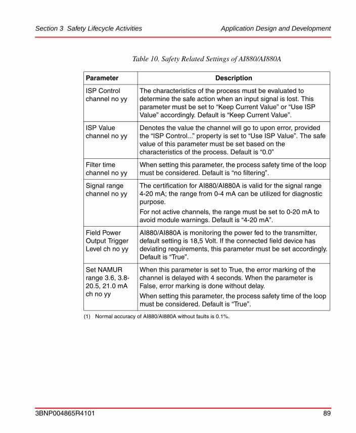
Section 3 Safety Lifecycle Activities Application Design and Development
ISP Control channel no yy
The characteristics of the process must be evaluated to determine the safe action when an input signal is lost. This parameter must be set to “Keep Current Value” or “Use ISP Value” accordingly. Default is “Keep Current Value”.
ISP Value channel no yy
Denotes the value the channel will go to upon error, provided the “ISP Control...” property is set to “Use ISP Value”. The safe value of this parameter must be set based on the characteristics of the process. Default is “0.0”
Filter time channel no yy
When setting this parameter, the process safety time of the loop must be considered. Default is “no filtering”.
Signal range channel no yy
The certification for AI880/AI880A is valid for the signal range 4-20 mA; the range from 0-4 mA can be utilized for diagnostic purpose.
For not active channels, the range must be set to 0-20 mA to avoid module warnings. Default is “4-20 mA”.
Field Power Output Trigger Level ch no yy
AI880/AI880A is monitoring the power fed to the transmitter, default setting is 18,5 Volt. If the connected field device has deviating requirements, this parameter must be set accordingly.Default is “True”.
Set NAMUR range 3.6, 3.8-20.5, 21.0 mA ch no yy
When this parameter is set to True, the error marking of the channel is delayed with 4 seconds. When the parameter is False, error marking is done without delay.
When setting this parameter, the process safety time of the loop must be considered. Default is “True”.
(1) Normal accuracy of AI880/AI880A without faults is 0.1%.
Table 10. Safety Related Settings of AI880/AI880A
Parameter Description
3BNP004865R4101 89

Application Design and Development Section 3 Safety Lifecycle Activities
DI880 High Integrity Digital Input Module
To ensure safe operation and adaptation to the process, DI880 must be configured according to the directions in Table 11.
Table 11. Safety Related Settings of DI880
Parameter Description
ModuleBus timeout
Denotes the time from communication with the input module is lost until the connected variables are error marked. Must be set in accordance with the process safety time of the fastest loop connected, but not shorter than 3 times the configured ModuleBus scan time. Default is “512 ms”.
Activate channel no yy
All I/O channels having a variable connected must be set active to avoid channel error. Default is “True”.
ISP Control channel no yy
The characteristics of the process must be evaluated to determine the safe action when an input signal is lost. This parameter must be set to “Keep Current Value” or “Use ISP Value” accordingly. Default is “Keep Current Value”.
ISP Value channel no yy
Denotes the value the channel will go to upon error, provided the “ISP Control...” property is set to “Use ISP Value”. The safe value of this parameter must be set based on the characteristics of the process. Default is “False”.
Filter time channel no yy
When setting this parameter, the process safety time of the loop must be considered. Default is “50 ms”.
Inverted (property)
Under the property tab it is possible to invert each variable connected to a digital channel. This property must be set in accordance with the positive/negative logic philosophy of the plant, see Software Architecture on page 71. Default is “False”.
90 3BNP004865R4101

Section 3 Safety Lifecycle Activities Application Design and Development
DO880 High Integrity Digital Output Module
To ensure safe operation and adaptation to the process, DO880 must be configured according to the directions in Table 12.
Table 12. Safety Related Settings of DO880
Parameter Description
ModuleBus timeout
Denotes the time from communication with the controller module is lost until the outputs of DO880 are brought to the safe state (de-energized). Must be set in accordance with the process safety time of the fastest loop connected, but not shorter than 3 times the configured ModuleBus scan time. Default is “512 ms”.
Activate channel no yy
All I/O channels having a variable connected must be set active to avoid channel error.
All I/O channels having no variable connected must be set not active (false). Default is “True”.
Output mode channel no yy
If the process requires a manual interaction to activate the output after a short circuit situation, this parameter must be set to “latch on short”. Default is “latch on short”.
Normal State channel no yy
Defines the channel behavior upon detection of a channel fault (by means of internal redundancy the channels have a fault tolerance of 1).
Normally energized (NE), de-energize to trip: Will be de-energized upon an internal channel error.
Normally de-energized (ND) energize to trip: Will follow the status received from the controller upon an internal channel error.
Continuous Control (CC): Same behavior as ND.
For all output types, safe state is defined as de-energize; i.e. upon fatal errors, (as CPU, power failure, loss of contact with controller), all outputs will be de-energized.Default is “Normally energized (NE)”.
3BNP004865R4101 91
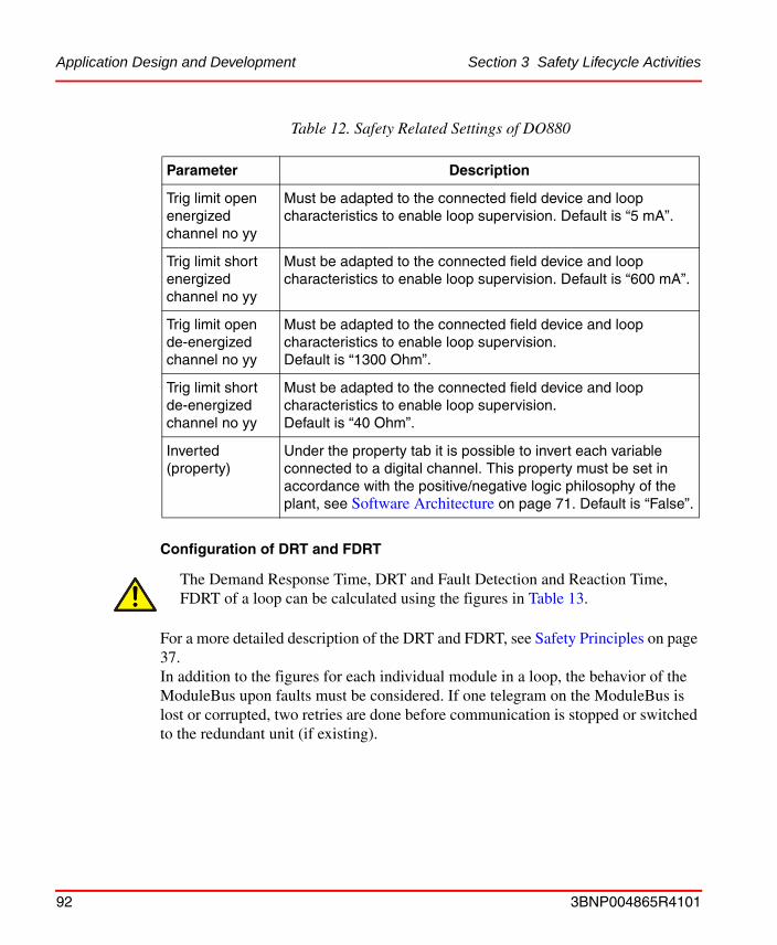
Application Design and Development Section 3 Safety Lifecycle Activities
Configuration of DRT and FDRT
For a more detailed description of the DRT and FDRT, see Safety Principles on page 37.In addition to the figures for each individual module in a loop, the behavior of the ModuleBus upon faults must be considered. If one telegram on the ModuleBus is lost or corrupted, two retries are done before communication is stopped or switched to the redundant unit (if existing).
Trig limit open energized channel no yy
Must be adapted to the connected field device and loop characteristics to enable loop supervision. Default is “5 mA”.
Trig limit short energized channel no yy
Must be adapted to the connected field device and loop characteristics to enable loop supervision. Default is “600 mA”.
Trig limit open de-energized channel no yy
Must be adapted to the connected field device and loop characteristics to enable loop supervision.Default is “1300 Ohm”.
Trig limit short de-energized channel no yy
Must be adapted to the connected field device and loop characteristics to enable loop supervision.Default is “40 Ohm”.
Inverted (property)
Under the property tab it is possible to invert each variable connected to a digital channel. This property must be set in accordance with the positive/negative logic philosophy of the plant, see Software Architecture on page 71. Default is “False”.
The Demand Response Time, DRT and Fault Detection and Reaction Time, FDRT of a loop can be calculated using the figures in Table 13.
Table 12. Safety Related Settings of DO880
Parameter Description
92 3BNP004865R4101

Section 3 Safety Lifecycle Activities Application Design and Development
Access Management Settings
Force Control
The AC 800M HI supports supervision and control with the number of forces entered during operation.
To enable forcing of I/O variables in a SIL classified application, the “maximum number of forces” property for the actual application must be configured (default is 0). This setting is available for each SIL classified application.
The force control acts on the “force” property of I/O variables (BoolIO, RealIO, DintIO and DwordIO) connected to I/O modules (both inputs and outputs). No other variables containing a force property will be affected by the force control, neither wills any variable not connected to an I/O channel be affected.
Table 13. Response times
DRT FDRT (max)
DI880 1.3 ms (max) 50 ms
AI880/AI880A 10 ms (max) 50 ms
DO880 15 ms (max) 50 ms
AC 800M HIProcessor UnitApplication cycle time
Configurablemin. 10 ms
Configurablemin. 1000 ms
ModuleBusCycle time
Configurable5 -100 ms
3 times the configured cycle time
The “maximum number of forces” property must be set based on the characteristics of each application and the operation philosophy of the plant.
The “maximum number of forces” property is only available in offline mode, and requires a download to take effect in the controller.
3BNP004865R4101 93

Application Design and Development Section 3 Safety Lifecycle Activities
The function block ForcedSignals and Control Module ForcedSignalsM can be used for interfacing this functionality from the 800xA Operator Workplace, from Control Builder M Professional and from user defined application programs. By means of these types, all forces per application can be reset.
If the force property of an I/O variable connected to an I/O module is set by IEC 61131-3 application code, it will take part in the counting of active forces, but the “maximum number of forces” property will not limit the possibility to induce forces in this way.
A variable forced in this way will be reset by the “Reset all Forces” function, but will be set again in the next application scan, provided the conditions are fulfilled.
For more information about the “Reset all Forces” input, see Physical I/O for Operator Interaction on page 65.
SIL Access Control
The possibility to change the content of variables in SIL applications in the AC 800M HI is restricted by the “Confirmed Write” and “SIL Access” functionality.
The “Access Level” must be configured for all variables that shall be possible to modify online from the 800xA Operator Workplace. Available settings are (Read only), (Confirm and Access Enable) and (Confirm).
• Read Only: Not possible to modify online, only viewing is possible.
• Confirm and Access Enable: Enables modification of values by means of the “Confirm Operation” dialog, provided the “Access Enable” input is enabled, see Physical I/O for Operator Interaction on page 65.
• Confirm: Enables modification of values by means of the “Confirm Operation” dialog.
The “force” property of I/O variables connected to I/O modules should not be controlled by IEC 61131-3 application code to avoid violation of the “maximum number of forces”.
The SIL Access level must be configured based on the characteristics of each variable and the operation philosophy of the plant.
94 3BNP004865R4101

Section 3 Safety Lifecycle Activities Application Design and Development
Default setting when instantiating a type is Read Only. Opening up for modification of a variable should only be done after careful considerations.
Confirmed Write Support
Confirmed Write Support is a function for enabling secure operation on objects in a SIL classified application. The Confirmed Write Support function brings up a Confirm Operation dialog, enabling the operator to verify and acknowledge the operation to be performed, see Operation Procedures on page 107, Figure 6 for example on the Confirm Operation dialog.
When creating a new type with operator faceplate for use on 800xA Operator Workplace, support for the confirmed write function must be implemented to enable operators to change values of the object (in SIL classified applications).This is done by adding a Confirmed Write Support aspect to the object to be operated (in addition to configuring the SIL Access Control as described above).
The faceplate and the configuration of the Confirmed Write Support aspect must be designed so it is easy for the operator to recognize object, property and value in the Confirm Operation dialog. Texts displayed in the Confirm Operation dialog must uniquely identify the operation to be performed.
User Defined Diagnostics
All SIL marked library types (Function Blocks and Control Modules) that include range check of input values, have an output parameter (ParError). The ParError is indicated on operator faceplates. If any system reaction is needed, this parameter must be used in an application program to perform the desired action.
Errors detected by the user defined diagnostic functions, can be reported to the system internal Error Handler by means of the Function Block ErrorHandler or Control Module ErrorHandlerM. In this way it is possible to achieve a consistent handling of all error types. The internal Error Handler functionality and configuration possibilities are described in Controller Settings and Restrictions on page 81.
If parameter errors on function blocks or control modules shall lead to a system reaction, this must be programmed in the application program.
3BNP004865R4101 95

Configuration Management Section 3 Safety Lifecycle Activities
Configuration Management
Procedures for Configuration Management must be established and used during the whole lifecycle of the application software.
Configuration Management comprise the running of an inventory list, showing the version of all SIS hardware (AC 800M HI with all connected interface and I/O modules) and software modules, as well as the version of all utility software like Control Builder M Professional, 800xA Operator Workplace and other tools utilized.
The following list is intended as input to the Configuration Management procedure:
• Identify the stage where formal configuration control shall be implemented
• Prevent unauthorized items (hardware and software) from entering service
• Tracking of changes resulting from observations and audits
• Tracking of work around and other temporary solutions
• Handling of revisions of input documentation
Test and Verification
This chapter contains guidelines on how testing and verification can be divided into sub tests performed during different phases of a project.
For planning and execution of regression testing after modifications, see the chapter Modification Testing on page 99.
Source Code Report
The source code report shows the complete source code for the current project in the Control Builder M Professional. Independent of what editor is used to create the code, the report is presented in “xml” format.The report shall be used to verify that the intended functionality is realized in the application code.
The source code report can be presented at any stage of the project, or during online operation of the system.
If a printed/saved Source Code Report is needed, this can be obtained from the menu: Remote System>Show Downloaded Items>Source Code Report.
96 3BNP004865R4101
Section 3 Safety Lifecycle Activities Test and Verification
For more details about the source code report, refer to the user manual 800xA - Control and I/O, Basic Control Software.
Difference Report
The difference report is generated after compilation and is presented before download to the AC 800M HI. The format and data is equal to that of the source code report, but only source code (and differences) for changed Applications and Controller Configurations is displayed. E.g. if the project contains two Applications App1 and App2, and only App1 has been changed since last download, only source code for App1 will be displayed.
For more details about the difference report, refer to the user manual 800xA - Control and I/O, Basic Control Software.
Test Mode
Test Mode can be used for offline testing of applications. Executing code in Test mode means that the code will be compiled and executed locally in the PC.
For more details about Test mode, refer to the user manual 800xA - Control and I/O, Basic Control Software.
Simulation
Simulation means that code is downloaded and executed in a simulation controller.
To enable download to a simulation controller, both the applications and the actual controller in the hardware tree must be marked with “simulate”.
In a simulation controller, the normal updating of I/O values from the I/O modules is stopped, enabling simulated test values to be entered. This can be done manually
The difference report cannot be used in Test Mode.
The only controller available for simulating SIL classified applications is the SoftController HI; the AC 800M HI cannot be configured as a simulation controller.
3BNP004865R4101 97

Test and Verification Section 3 Safety Lifecycle Activities
from Control Builder M Professional, or by a test program executing in the simulation controller.
To avoid dangerous situations, the following restrictions apply:
For more details about Simulation, refer to the user manual 800xA - Control and I/O, Basic Control Software.
Hardware Testing
Testing must be performed on the project specific hardware to show that the hardware is assembled and configured correctly and works according to its specifications.
Software Module Testing
Testing of project specific Function Blocks and Control Module types must be performed to verify their specified functionality.
The logic functions of such types can be verified in Test Mode or Simulation as described above, while execution time and memory consumption must be verified in an AC 800M HI.
Software Integration Testing
These tests shall demonstrate that all application software modules and components interact correctly with each other and with the underlying embedded software.
Before formal testing commence, the Source Code Report must be generated and reviewed, see Difference Report on page 97.
This review will secure that the actual source code realizes the intended functionality. The need for testing (and the probability for finding errors) will be
A simulation marked application, or an application containing a simulation marked program, can only be downloaded to a simulation marked controller.
The Source Code Report must be carefully reviewed to reveal any failures introduced during programming and editing the applications.
98 3BNP004865R4101

Section 3 Safety Lifecycle Activities Test and Verification
significantly reduced, provided a proper desk check is performed on the source code report.
Software Integration testing can be done either by using the AC 800M HI or by means of the Test Mode or Simulation functions described above.
Integration of Application Software with the System Hardware
These tests shall verify that all software and hardware modules of an AC 800M HI function together and interface with each other as a complete system.
These tests must verify I/O configurations and other external interfaces. Correct function of redundant components must be verified.
These tests must be performed using the AC 800M HI hardware.
System Integration Testing
If the project contains functions that are dependent of more than one controller, or other external systems, these functions must be verified in a complete system setup, comprising all involved sub systems.These kinds of tests can be done in a staging area or after installation in the actual plant.
Modification Testing
Impact Analysis
If modifications are done to hardware or software parts that already are tested, an impact analyze must be performed to identify all parts of the system that might be influenced by the modification.For application changes, the “difference report” presented after compilation (see Difference Report on page 97) provides information that will be useful in verifying the completeness of the impact analysis.
Functional Testing
The changed parts of the system must be tested according to the procedures originally used for such testing the first time. If the modification is done on a
3BNP004865R4101 99

Test and Verification Section 3 Safety Lifecycle Activities
Function Block type or Control Module type, functional re-testing must be performed on the instances of the type.
Regression Testing
Regression testing must be performed to verify that no unintended effects of the modification have occurred. Such regression testing must cover all parts of the system identified in the impact analysis. The level of regression testing must be determined based on a competent judgment of the extent and the complexity of the performed modification.
For additional considerations regarding modifications during the operation period, refer to Modification during Operation on page 112.
Modifications affecting I/O connections must be verified by testing in the running AC 800M HI controller.
100 3BNP004865R4101

Section 3 Safety Lifecycle Activities Installation and Commissioning
Installation and Commissioning
Transportation and Storage
Requirements for environmental conditions during transportation and storage are described in the user manual 800xA - Control and I/O, AC 800M Controller Hardware.
Mechanical Completion
Upon receipt of the equipment at the site of installation, it is important to secure satisfactory environmental conditions.
For a complete overview of environmental conditions, see the user manuals 800xA - Control and I/O, AC 800M Controller Hardware and Control IT S800 I/O, General Information and Installation.
After packaging and transportation material is removed, the equipment must be checked for any visual signs of physical damage during transportation.
Electrical Completion
During installation of cables and powering of the system, all connections to external equipment and field instruments should be disconnected to avoid damage of equipment in case of wrong polarities or voltage levels.
Earth connections must be in place and verified before power is connected to the system.
If required environmental conditions during operation are not yet established, interim measures must be taken to avoid damage of the equipment.
To ensure a safe mechanical installation and assembling of the equipment at installation site, the guidance described in the user manuals 800xA - Control and I/O, AC 800M Controller Hardware and Control IT S800 I/O, General Information and Installation must be followed.
3BNP004865R4101 101

Program Download and Startup Section 3 Safety Lifecycle Activities
The power source must be connected and verified for polarity and voltage level before power is turned on to the system.
Program Download and Startup
The application which is to be updated from changes in the download is stopped and the 1131-task execution is delayed for a short period of time during the online download. During this time period the output signals are not updated, but keep their current values. The maximum length of the time period the outputs are not updated can be determined by using the following formulas:
• If the task Cycle time is <= FDRT:3 times the FDRT.
• If the task Cycle time is > FDRT:FDRT + 3 times the task Cycle time.
If the stop period exceeds the limit determined by the formulas, the controller is halted and the outputs are automatically brought to the safe state.
To ensure a safe electrical installation and power up of the equipment at installation site, the guidance described in the user manuals 800xA - Control and I/O, AC 800M Controller Hardware and Control IT S800 I/O, General Information and Installation must be followed.
Before connecting any external devices to the AC 800M HI, voltage level and polarity must be verified.
To ensure a safe download and startup of applications to the AC 800M HI, the procedure described in Program Download and Startup on page 102 must be followed.
During online download, the user must take appropriate precautions dependant of the properties and the time demands of the process under control.
102 3BNP004865R4101

Section 3 Safety Lifecycle Activities Program Download and Startup
After the first download of a SIL marked application to an AC 800M HI controller, subsequent downloads are protected by the “Access enable” input on the SM810, se description under Operator Interface on page 65.
Note: If the AC 800M HI is empty or running only non-SIL applications, this restriction is not valid.
When downloading applications or application changes to an AC 800M HI, the following procedure must be followed:
• Enable download by activating the “Access enable” input.
• Select the controller(s) to be updated.
• Select warm or cold restart for each application (the first time a download is performed, cold restart is automatically selected), based on the retain value philosophy described in Application Design and Development on page 70.
• If there are any compilation errors or warnings displayed, a careful judgment must be done prior to continuing (or canceling) the download (not possible to continue with errors).
• The difference report1 presented on the screen must be carefully analyzed. Verify that all the intended changes are correctly implemented and do also verify for all SIL marked applications that no unintended changes are done.If cold restart is selected, the Source Code Report part of the difference report contains an item named Cold Retain and Instance specific values. Verify for all SIL marked applications that applied cold retain values are correct before continuing with the download.Select continue or cancel.
• After the download, open the “downloaded items” display and verify that the correct versions of all applications and controller configurations are downloaded and running, by comparing the compilation date and signature for each item with the corresponding information found in the “difference report” or “source code report”.
The “Access enable” input must be enabled to allow download to an AC 800M HI controller (valid for SIL and non-SIL applications).
1. The first time an application is downloaded, the difference report is empty, for more information, see Difference Report on page 97.
3BNP004865R4101 103

Commissioning Test Activities Section 3 Safety Lifecycle Activities
• Check that all tasks in AC 800M HI are running with sufficient margin to the specified cycle time.
• Perform testing as planned during engineering, see Test and Verification on page 96.
• The system is considered operating safe when these steps are performed.
For details on how to perform the above tasks, refer to the user manual 800xA - Control and I/O, Basic Control Software.
Controller Restart
Pressing the INIT button manually restarts the controller. A short press (less than 3 seconds) results in a cold restart, hence only variables with the attribute cold retain are maintained.
A long press on the INIT button results in a complete reset of the controller and a new download of all applications is needed. Also in this case, variables with the attribute cold retain are maintained, provided they are stored in the aspect server.
A power failure, in combination with too low battery capacity in the controller, will have the same effect as a long press on the INIT button.
Commissioning Test Activities
Commissioning test activities shall include field devices and other external components needed to perform a complete function. The aim of the test is to verify that all components work together in their real environment.
The difference report will not be automatically saved by Control Builder M Professional, thus if it is needed for future reference it must be printed to file or paper and stored manually.
It is recommended to verify that the intended re-start (warm- or cold re-start) has been performed by using the controller log.
104 3BNP004865R4101

Section 3 Safety Lifecycle Activities Commissioning Test Activities
Procedures for handling deviations identified during the commissioning testing must be established. The procedures must cover necessary impact analyses and re-engineering activities to be able to handle all deviations safely, also if the deviation origins from an early engineering phase, or from input documents to the engineering. For guidance in testing of such modifications, see Modification Testing on page 99.
If parts of the safety functions controlled by the AC 800M HI are put operational, while other parts are still under commissioning, procedures must be established to secure the integrity of the operational parts.
3BNP004865R4101 105

Safety Validation Section 3 Safety Lifecycle Activities
Safety ValidationThe objective of the safety validation is to validate, through inspection and testing that all safety functions are in operation as specified.Specific validation procedures must be developed for the actual plant; this chapter contains some items to consider when developing the procedures.
Verify that all safety functions are tested and in operation.
Verify that tests are done to demonstrate correct system behavior upon loss of utilities like electrical power, air or hydraulics.
Verify that tests are done to demonstrate correct system behavior upon fault of redundant parts.
Verify that tests are done to demonstrate correct system behavior upon loss of communications.
Verify that a correct backup of all software exists and are stored securely.
Verify that all relevant documentation is updated and stored securely.
The validation should include the following items to ensure that all temporary degradations of the safety functions are removed:
• Verify that all applications are marked with the correct SIL mark
• Verify that no warnings are presented during compilation and download
• Verify that all forces and bypasses in the application software are removed
• Verify that all temporary bypasses and overrides in the hardware, including field loops are removed.
• Verify that all system components (including redundant parts) are running without any error LEDs, or error messages
106 3BNP004865R4101

Section 3 Safety Lifecycle Activities Operation and Maintenance
Operation and MaintenanceThis subsection contains information on how to maintain the required SIL of each safety instrumented function during the operation period.
Operation and Maintenance Planning
Operation and maintenance planning for the SIS shall be carried out, this requirement ensures that functional safety continues beyond the design, production, installation and commissioning of the system. Guidance and procedures shall be provided to enable the organization responsible for Operation and Maintenance to maintain the intended safety levels of the safety instrumented functions.
The Operation and maintenance plan shall include:
• Start-up and shutdown procedures of the process
• Procedures for normal operation
• Maintenance activities for sensors, actuators and other field devices
• Maintenance activities for the SIS
• Allocation of responsibilities for the various tasks
Operation Procedures
Procedures shall be established to secure safe operation of the SIS under all process conditions and states.
As described in chapter Access Management Settings on page 93, the operator’s possibility to change values in an AC 800M HI can be configured to fit the operation philosophy of the plant. The configured behavior of the system must be reflected in the operation procedures.
The utilization of the Access Enable key switch and the Reset all Forces panel button as described in Physical I/O for Operator Interaction on page 65 must be reflected in the operation procedures.
All operations on an object in a SIL application, must be confirmed by the operator by selecting yes in the Confirm Operation dialog, see Figure 6 below.
3BNP004865R4101 107

Operation Procedures Section 3 Safety Lifecycle Activities
Figure 6. Confirm Operation dialog
It is the operator’s responsibility to verify that the operation performed in the faceplate corresponds to the operation indicated in the Confirm Operation dialog, which is the system’s interpretation of the intended operation.
Alarm acknowledge is not invoking the Confirm Operation dialog, nor is it dependent of the SIL access setting, i.e. there is no restriction on acknowledging alarms in SIL applications.
The operation procedures must emphasize the operator’s responsibility to verify his operations by checking the Confirm Operation dialog.
It is not possible to enable/disable alarms in a SIL classified application from the Alarm List on the 800xA Operator Workplace.
If the HART routing functionality of AI880A is not restricted by the configuration settings of the module, the operation procedures must include restrictions for use of this function.
108 3BNP004865R4101

Section 3 Safety Lifecycle Activities Maintenance Procedures
Maintenance Procedures
Routine Maintenance
Procedures shall be established for performing necessary maintenance to the SIS, see also guidelines given in Proof Testing and Inspection on page 110.The procedures shall include measures to be taken to maintain the safety functions during testing, or if necessary, what additional steps need to be implemented to reduce the risk during testing.
Procedures shall also be established to secure that test equipment used during maintenance activities are properly calibrated and maintained.
For requirements for routine maintenance of the AC 800M HI, see user manuals 800xA - Control and I/O, AC 800M Controller Hardware and Control IT S800 I/O, General Information and Installation.
Fault Finding and Repair
The AC 800M HI has extensive self-test and diagnostic functions that report all detected failures promptly. The consequence of a faulty module depends on the nature of the fault and the level of redundancy installed in the actual configuration:
• If available, the system maintains safety by switching to a redundant unit.
• If no redundant unit is available, the AC 800M HI deactivates its outputs and thus the process is brought to the safe state.
Procedures shall be developed and implemented to govern the reaction to detected faults in the SIS. The following warnings and information shall be reflected:
In redundant DO880 configurations, faulty DO880 modules must be removed from the system within the repair time of 72 hours.
Reported faults should be repaired promptly to re establish the availability of the installation.
The Control Builder M Professional can be used for monitoring values in the AC 800M HI, but it is not possible to change values in SIL classified applications.
3BNP004865R4101 109
Training and Qualifications Section 3 Safety Lifecycle Activities
For information and guidelines related to fault finding and module replacement, see the user manuals 800xA - Control and I/O, AC 800M Controller Hardware and Control IT S800 I/O, General Information and Installation.
Training and Qualifications
The general guidelines regarding qualifications and allocation of responsibilities given in chapter Organization and Resources on page 46 apply.
The training of operators shall emphasize:
• The safety functions implemented in the SIS
• The hazards the SIS is protecting against
• Routines and procedures for operation of bypass switches
• Routines and procedures for operation of manual shutdown/activation switches
• Procedures for action upon SIS diagnostic alarms
The training of maintenance personnel must be adapted to the level of maintenance they shall perform. Routine testing of field devices requires different skills than faultfinding and module replacement in the SIS.
Proof Testing and Inspection
In most system configurations there will be some elements of the SIF that will not be covered by the system’s automatic diagnostic functions (e.g. sensors, actuators and field wiring). To avoid fault accumulation within those elements, periodic proof testing of the safety instrumented functions shall be conducted. The proof test interval shall be calculated using PFD calculations. This will probably result in different test intervals for different parts of the SIS.
The proof test interval required for the AC 800M HI is:
• 10 years for central processing unit (PM865 and SM810)
• 8 years for I/O system and other peripherals
These test intervals are used in the manual 800xA - Safety, Reliability Calculations.
The safety instrumented system (including field devices) shall be visually inspected at regular intervals, to detect any observable damages.
110 3BNP004865R4101

Section 3 Safety Lifecycle Activities Proof Testing and Inspection
Records and procedures for handling findings from both proof testing and inspections shall be created.
3BNP004865R4101 111

Modification during Operation Section 3 Safety Lifecycle Activities
Modification during Operation
Application Modifications
In order to maintain the safety integrity level of the safety system during the operation period, it is of vital importance that proper procedures for modifications are established and implemented.Such procedures must secure that all modifications to the SIS are properly planned, reviewed and approved prior to implementing the change.
The following list is intended as items to consider when establishing procedures for modification during operation:
• Impact analysis to identify all influenced parts of the system
• Properly trained and qualified personnel
• Guidelines described in System Design and Engineering on page 56
• Guidelines described in Application Software on page 69
• Guidelines described in Modification Testing on page 99
• Will the modification be implemented while the process is running?
– Evaluate the need for temporary measures to maintain safety integrity during the implementation.
– Evaluate the need for temporary measures to avoid process upsets during the implementation.
• Procedure Program Download and Startup on page 102
If the system is configured as a combined BPCS and SIS, changes can be done to the BPCS part without affecting the SIS.
To verify that no unintended changes to the SIL part of the system are done, always examine the difference report before download, (see Difference Report on page 97).
112 3BNP004865R4101

Section 3 Safety Lifecycle Activities Firmware Upgrade
Firmware Upgrade
Firmware is the system software in controller CPUs, and units such as SM810 and communication interfaces on the CEX-Bus. Upgrading of firmware by downloading new firmware versions is done from Control Builder M Professional.
Firmware can only be upgraded when the AC 800M HI has no application program.
Prior to removing an application from an AC 800M HI, cold retain values can be saved to the aspect directory.
When upgrading firmware of an AC 800M HI, the following procedure must be followed.
• Save cold retain values to the aspect directory (if needed).
• Select the controller to be upgraded.
• Enable removal of SIL classified applications by activating the “Access enable” input.
• Remove all applications from the controller.
• Select the unit to be upgraded (PM865 or SM810).
• Select the firmware version to be downloaded.
• After the download, the controller is restarted (automatically), then open the “Show Firmware Information” display and verify that the correct versions of firmware are downloaded.
• Download the application to the controller by following the procedure described in Program Download and Startup on page 102.
For details on how to perform the above tasks, refer to the user manual 800xA - Control and I/O, Basic Control Software.
To ensure a safe firmware upgrade of AC 800M HI, the procedure described in Firmware Upgrade on page 113 must be followed.
The “Access enable” input must be enabled to allow removal of SIL classified applications from AC 800M HI.
3BNP004865R4101 113

Configuration Management Section 3 Safety Lifecycle Activities
Configuration Management
For modifications done during operation, it is vital to continue the Configuration Management established during the engineering phase. See Configuration Management on page 96.
114 3BNP004865R4101
Section 3 Safety Lifecycle Activities Decommissioning
DecommissioningPrior to decommissioning the system, proper planning and procedures must be established.
An analysis shall be performed to determine the impact on functional safety from the proposed decommissioning activities. The assessment shall consider:
• Functional safety during execution of the decommissioning activities
• Impact on adjacent operating units and facilities
– Including interfaces to other safety instrumented systems
• Sequence of decommissioning
– Is there a need to keep parts of the safety functions operational during some stages of the decommissioning?
• Identify need for establishing temporary safety measures during the decommissioning activities.
All parts of the safety system shall be disposed according to national laws and regulations regarding environmental aspects.
3BNP004865R4101 115

Decommissioning Section 3 Safety Lifecycle Activities
116 3BNP004865R4101

Appendix A Certified Library
IntroductionThe Control Builder M Professional is supplied with predefined libraries of “System Functions”, “Function Block Types” and “Control Module Types”. This appendix provides lists of library elements that are certified for use in SIL marked applications.Other library elements supplied with the system, but not listed here, is intended for use in non-SIL marked applications in the AC 800M HI controller.
The types are briefly described in the manual 800xA - Control and I/O, Addendum and in more detail in Control Builder M Professional Online Help.
System Functionsabs
add1
addsuffix
and
ASCIIStructToString
bool_to_dint
bool_to_dword
bool_to_int
bool_to_real
1. The Add function is not certified for adding strings
3BNP004865R4101 117

System Functions Appendix A Certified Library
bool_to_string
bool_to_uint
bool_to_word
Bool16ToDint
Bool32ToDint
date_and_time_to_string
dint_to_bool
dint_to_dword
dint_to_int
dint_to_real
dint_to_string
dint_to_time
dint_to_uint
dint_to_word
div
dword_to_bool
dword_to_dint
dword_to_int
dword_to_string
dword_to_uint
dword_to_word
eq
ExecuteControlModules
expt
FirstScanAfterApplicationStart
FirstScanAfterPowerUp
118 3BNP004865R4101

Appendix A Certified Library System Functions
ge
GetActualIntervalTime
GetIntervalTime
GetSystemDT
gt
int_to_bool
int_to_dint
int_to_dword
int_to_real
int_to_string
int_to_uint
int_to_word
le
len
limit
lt
match
max
min
mod
move
mul
mux
ne
not
or
3BNP004865R4101 119

System Functions Appendix A Certified Library
ReadStatusZeroDivInt
ReadStatusZeroDivReal
real_to_bool
real_to_dint
real_to_int
real_to_string
real_to_time
real_to_uint
rol
ror
sel
shl
shr
sqrt
string_to_bool
string_to_date_and_time
string_to_dint
string_to_dword
string_to_int
string_to_real
string_to_time
string_to_uint
string_to_word
sub
SystemDTToLocalDT
time_to_dint
120 3BNP004865R4101
Appendix A Certified Library System Functions
time_to_real
time_to_string
Timer
TimerElapsed
TimerElapsedMS
TimerHold
TimerReset
TimerStart
uint_to_bool
uint_to_dint
uint_to_dword
uint_to_int
uint_to_real
uint_to_string
uint_to_word
word_to_bool
word_to_dint
word_to_dword
word_to_int
word_to_string
word_to_uint
xor
3BNP004865R4101 121
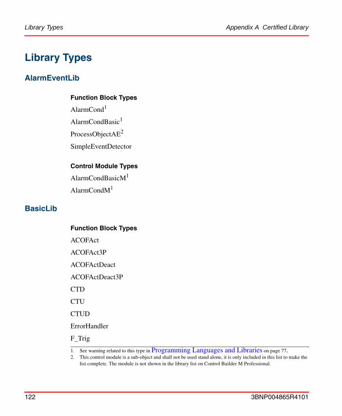
Library Types Appendix A Certified Library
Library Types
AlarmEventLib
Function Block Types
AlarmCond1
AlarmCondBasic1
ProcessObjectAE2
SimpleEventDetector
Control Module Types
AlarmCondBasicM1
AlarmCondM1
BasicLib
Function Block Types
ACOFAct
ACOFAct3P
ACOFActDeact
ACOFActDeact3P
CTD
CTU
CTUD
ErrorHandler
F_Trig
1. See warning related to this type in Programming Languages and Libraries on page 77.2. This control module is a sub-object and shall not be used stand alone, it is only included in this list to make the
list complete. The module is not shown in the library list on Control Builder M Professional.
122 3BNP004865R4101

Appendix A Certified Library BasicLib
ForcedSignals
PulseGenerator
R_Trig
RS
SR
TimerD
TimerOffHold
TimerOnHold
TimerOnOffHold
TimerPulseHold
TimerPulseHoldDel
TimerU
TOf
TOn
TP
Trigger
Control Module Types
ErrorHandlerM
ForcedSignalsM
GroupStartObjectConn
3BNP004865R4101 123

FireGasLib Appendix A Certified Library
FireGasLib
Control Module Types
CO2
Deluge
FGOutputOrder
Sprinkler
IconLib
Control Module Types
All Control Module types in IconLib are for presentation purpose only. They are all certified for use in SIL marked applications.
MMSCommLib
Function Block Types
MMSConnect1
MMSDef4Bool1
MMSDef4BoolIO1
MMSDef4Dint1
MMSDef4DintIO1
MMSDef4Real1
MMSDef4RealIO1
MMSRead4Bool1
MMSRead4BoolIO1
MMSRead4Dint1
1. See warning related to this type in Software Architecture on page 71
124 3BNP004865R4101

Appendix A Certified Library ProcessObjBasicLib
MMSRead4DintIO1
MMSRead4Real1
MMSRead4RealIO1
Control Module Types
MMSDef2DwordM
MMSRead2DwordM
ProcessObjBasicLib
Function Block Types
BiCore
BiDelayOfCmd
BiSimple
DetectOverrideBi
DetectOverrideUni
DetectOverrideVoteBi
DetectOverrideVoteUni
Jog
PrioritySup
UniCore
UniDelayOfCmd
UniSimple
Control Module Types
BiSimpleM
1. See warning related to this type in Software Architecture on page 71
3BNP004865R4101 125

ProcessObjExtLib Appendix A Certified Library
DisplayOverrides1
FaceplateBiSimple1
FaceplateBiSimpleM1
FaceplateUniSimple1
FaceplateUniSimpleM1
IconProcObj1
InfoOverideBi1
InfoOverideBiM1
InfoOverideBiSimple1
InfoOverideUni1
InfoOverideUniM1
InfoOverideUniSimple1
InfoParBi1
InfoParBiGroupStart1
InfoParBiM1
InfoParUni1
InfoParUniGroupStart1
InfoParUniM1
UniSimpleM
ProcessObjExtLib
Function Block Types
Bi
LevelDetection
1. This control module is a sub-object and shall not be used stand alone, it is only included in this list to make the list complete. The module is not shown in the library list on Control Builder M Professional.
126 3BNP004865R4101

Appendix A Certified Library ProcessObjExtLib
MotorBi
MotorUni
OETextBi
OETextUni
OETextValveUni
Uni
ValveUni
Control Module Types
BiM
FaceplateBi1
FaceplateBiM1
FaceplateMotorBi1
FaceplateMotorBiM1
FaceplateMotorUni1
FaceplateMotorUniM1
FaceplateUni1
FaceplateUniM1
FaceplateValveUni1
FaceplateValveUniM1
GroupStartIconBi1
GroupStartIconMotorBi1
GroupStartIconMotorUni1
GroupStartIconUni1
GroupStartIconValveUni1
1. This control module is a sub-object and shall not be used stand alone, it is only included in this list to make the list complete. The module is not shown in the library list on Control Builder M Professional.
3BNP004865R4101 127

SignalLib Appendix A Certified Library
InfoParMotorBi1
InfoParMotorBiM1
InfoParMotorUni1
InfoParMotorUniM1
InfoParValveUni1
InfoParValveUniM1
MotorBiM
MotorUniM
UniM
ValveUniM
SignalLib
Function Block Types
SignalBool
SignalInBool
SignalInReal
SignalOutBool
SignalReal
SignalSimpleInReal
Control Module Types
SignalBoolCalcInM
SignalBoolCalcOutM
SignalInBoolM
SignalInRealM1. This control module is a sub-object and shall not be used stand alone, it is only included in this list to make the
list complete. The module is not shown in the library list on Control Builder M Professional.
128 3BNP004865R4101
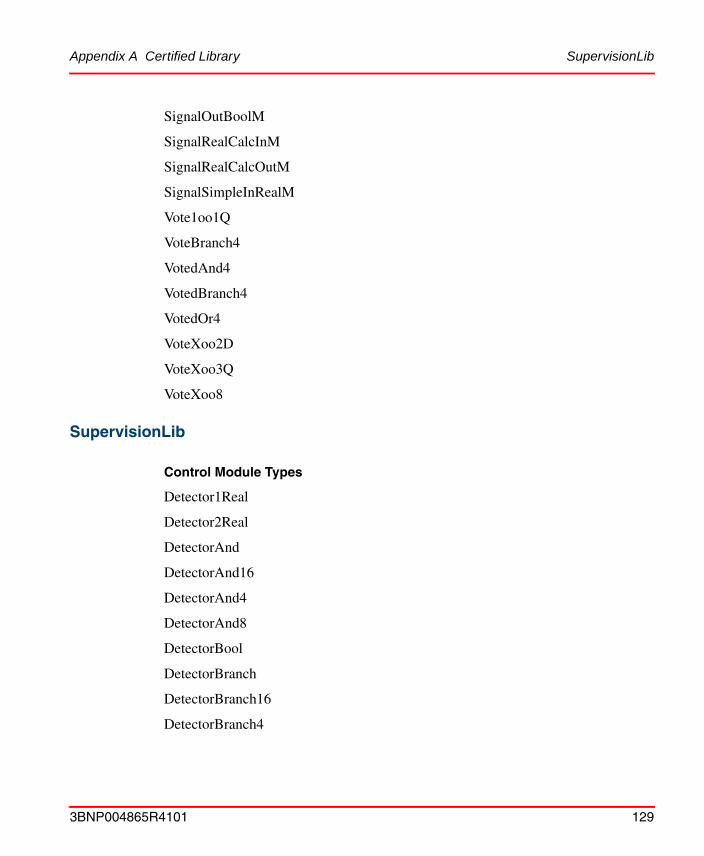
Appendix A Certified Library SupervisionLib
SignalOutBoolM
SignalRealCalcInM
SignalRealCalcOutM
SignalSimpleInRealM
Vote1oo1Q
VoteBranch4
VotedAnd4
VotedBranch4
VotedOr4
VoteXoo2D
VoteXoo3Q
VoteXoo8
SupervisionLib
Control Module Types
Detector1Real
Detector2Real
DetectorAnd
DetectorAnd16
DetectorAnd4
DetectorAnd8
DetectorBool
DetectorBranch
DetectorBranch16
DetectorBranch4
3BNP004865R4101 129

SupervisionLib Appendix A Certified Library
DetectorBranch8
DetectorLoopMonitored
DetectorOr
DetectorOr16
DetectorOr4
DetectorOr8
DetectorRemote
DetectorVote
OrderBranch
OrderBranch16
OrderBranch4
OrderBranch8
OrderMMSDef16
OrderMMSRead16
OrderOr
OrderOr16
OrderO4
OrderOr8
OutputBool
OutputOrder
OverrideControlInterface
OverviewConversion
SiteOverview
SiteOverviewMMSDef
SiteOverviewMMSRead
SiteOverviewOr4
130 3BNP004865R4101

Appendix A Certified Library SupervisionLib
SupervisionOverview
3BNP004865R4101 131

SupervisionLib Appendix A Certified Library
132 3BNP004865R4101

Appendix B Certified HW Components Safety-related hardware components
Appendix B Certified HW Components
Safety-related hardware componentsFor information on version numbers of the certified modules, please refer to the TÜV certification report.
The following system components are certified “safety-related”. This allows the components to be used to process safety critical signals and functions:
Table 14. Safety-related hardware components
Module Description
AI880 Safety Analog Input Module
AI880A Safety Analog Input Module with Hart support
DI880 Safety Digital Input Module
DO880 Safety Digital Output Module
PM865 Processor Module
SM810 Safety Module
SS823 Power Voting Unit with over voltage protection
3BNP004865R4101 133

Safety-relevant hardware components Appendix B Certified HW Components
Safety-relevant hardware componentsThe following system components are ‘safety-relevant’, i.e. they are supporting hardware to be attached to the safety system:
Table 15. Safety-relevant hardware components
Module Description
BC810 CEX communication/breakout box
TB820 Cluster Modem for single electrical ModuleBus
TB825 Cluster Modem for single electrical ModuleBus
TB840 Cluster Modem for redundant electrical ModuleBus
TP830 Base-Plate, PM865
TP855 Base-plate, SM810
TP857 Base-plate, BC810
TU810 Single MTU for DI880 / DO880, single ModuleBus
TU812 Single MTU for DI880 / DO880, single ModuleBus
TU814 Single MTU for DI880 / DO880, single ModuleBus
TU830 Single MTU for DI880 / DO880, single ModuleBus
TU838 Single MTU for DI880, single ModuleBus extension
TU840 MTU for TB840 (single electrical ModuleBus)
TU841 MTU for TB840 (redundant electrical ModuleBus)
TU842 Redundant MTU for DI880 / DO880
TU843 Redundant MTU for DI880 / DO880
TU844 Redundant MTU for AI880 / AI880A
TU845 Redundant MTU for AI880 / AI880A
134 3BNP004865R4101
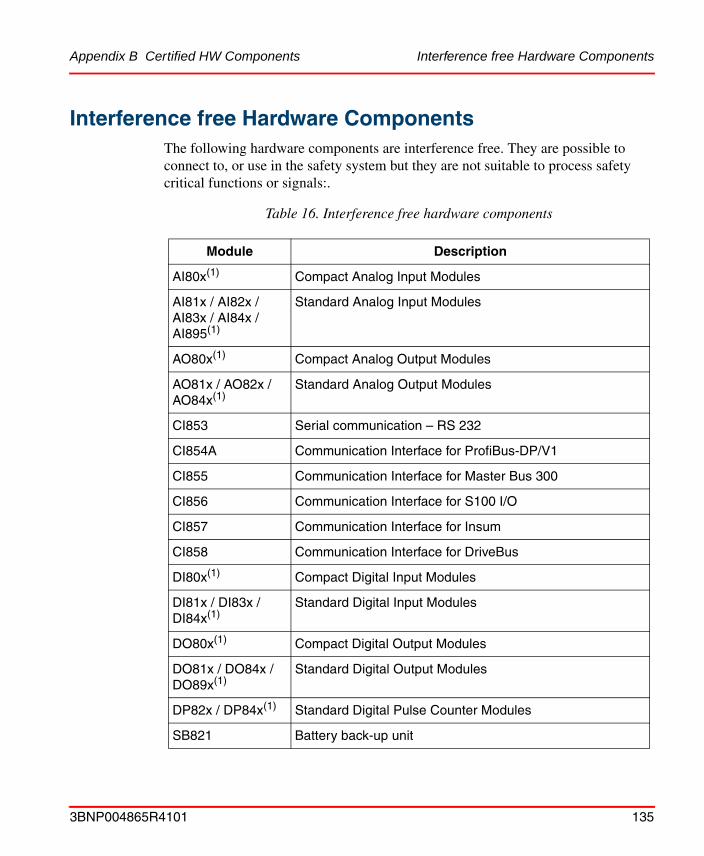
Appendix B Certified HW Components Interference free Hardware Components
Interference free Hardware ComponentsThe following hardware components are interference free. They are possible to connect to, or use in the safety system but they are not suitable to process safety critical functions or signals:.
Table 16. Interference free hardware components
Module Description
AI80x(1) Compact Analog Input Modules
AI81x / AI82x / AI83x / AI84x / AI895(1)
Standard Analog Input Modules
AO80x(1) Compact Analog Output Modules
AO81x / AO82x / AO84x(1)
Standard Analog Output Modules
CI853 Serial communication – RS 232
CI854A Communication Interface for ProfiBus-DP/V1
CI855 Communication Interface for Master Bus 300
CI856 Communication Interface for S100 I/O
CI857 Communication Interface for Insum
CI858 Communication Interface for DriveBus
DI80x(1) Compact Digital Input Modules
DI81x / DI83x / DI84x(1)
Standard Digital Input Modules
DO80x(1) Compact Digital Output Modules
DO81x / DO84x / DO89x(1)
Standard Digital Output Modules
DP82x / DP84x(1) Standard Digital Pulse Counter Modules
SB821 Battery back-up unit
3BNP004865R4101 135

Interference free Hardware Components Appendix B Certified HW Components
The following hardware components are interference free. However, they shall not be used on ModuleBus cluster 0, i.e. the built-in electrical ModuleBus, and they shall not be used on a ModuleBus cluster in combination with the safety-related DO880 modules:
SD821 Power supply 120/230V AC mains supply (24V DC/2.5A)
SD822 Power supply 120/230V AC mains supply (24V DC/5A)
SD823 Power supply 120/230V AC mains supply (24V DC/10A)
TC562 Short-distance modem (RS-232)
TP853 Base-plate for CI853 / CI855 / CI857
TP854 Base-plate for CI854A
TP856 Base-plate for CI856
TP858 Base-plate for CI858
(1) This table applies only for I/O modules that are specified for field voltages lower than or equal to 24 V
d.c. I/O modules specified for higher voltages are described in Table 17.
Table 17. Interference free hardware components
Module Description
DI802 / DI803 Compact Digital Input Modules
DI811 / DI820 / DI821 / DI831 / DI885
Standard Digital Input Modules
DO802 Compact Digital Output Modules
DO820 / DO821 Standard Digital Output Modules
Table 16. Interference free hardware components
Module Description
136 3BNP004865R4101

INDEX
Numerics800xA Operator Workplace 66, 95, 108
AAccess Control 94Access Enable 65, 107Access Management 93AI880 88, 93AI880A 62AlarmCond 78Any Force Active 65 to 66Application 71, 74, 81application software 69Aspect directory 67
BBC810 61BPCS 72, 112Bulk data manager 67
CCASE 79Caution 23CEX 59, 61CI851 64CI852 64CI858 64CI860 64CI862 64cold restart 75cold retain 75, 103Commissioning 104communication 64, 72, 74
compiler 79Compiler Test Application 71Configuration Management 50, 96Confirm Operation 95, 107Confirmed Write 66, 78, 94 to 95Confirmed Write Support 95Continuous Mode 53Control Builder M Professional 67, 79Control Module Types 77Control Modules 72Controller Restart 104CTA 71Cycle Time 73
DDemand Mode 53DI880 63, 90, 93diagnostic 95, 109difference report 97, 103Digital Inputs 65Digital Outputs 65DO880 63, 91, 93documentation 35download 103DRT 37, 92
EEN 80Enable Input 80enclosure 67environment 43, 67, 101Error Handler 82, 87, 95ESD 82
3BNP004865R4101 137

Index
EXIT 79
FF&G 82Faultcount 73FDRT 37, 73, 81, 92Filter time 89Firmware 113FirstScanAfterPowerUp 75FOR 79Force Control 74, 93ForcedSignals 65, 94FPL 77Function Block Types 77Function Designer 67FVL 77
HHART 62, 88, 108hazard 51
II/O Signal Failure 76Impact Analysis 99, 112Implicit Cast 79Information 23installation 101Instruction List 79ISP 89 to 90
LLadder Diagram 79Languages 77Latency 87Libraries 77 to 78logic 74Loops In ST 79LVL 77
MMMS 64MMSDef2DwordM 72 to 73MMSRead2DwordM 72 to 73modifications 112ModuleBus 60, 87, 90 to 91, 93
NNAMUR 89ND 91NE 91Nested If or Case 79Normally de-energized 91Normally energized 91number of forces 74, 93
OOverrun 81
Ppeer-to-peer 64, 74PELV 64PM865 59, 110positive logic 74power failure 75proof test 110PST 37
QQuality Management System 45
RRCU 59redundancy 42, 59, 109REPEAT 79Reset all Forces 65, 94, 107restart 75, 103 to 104restrictions 43, 79, 81Retain Variables 75, 103
138 3BNP004865R4101

Index
RETCN 80RETURN 80Reuse assistant 67risk 51Risk Reduction Factor 52
SS800 I/O system 61Safety Accuracy 88Safety Functions 52safety lifecycle 21, 51Safety Management System 45Safety Requirement Specification 53, 69Safety Validation 70, 106SD821 65SD822 65SD823 65SELV 64Sequence Of Event 63SFC 79shunt stick 63SIL 72, 78SIL Access Control 66, 94Simulation 97Simultaneous Execution in SFC 79SIS 51, 112Site Planning 67SM810 59, 110SoftController 97source code report 96, 98, 103SS823 64System Alarm 65 to 66, 83System Functions 77
Ttask 87Test Mode 97Time Critical 87Tip 23training 110
TÜV 21
Uuser defined diagnostic 95user defined libraries 78user manuals 35
VVirtual Machine Test 71VMT 71VMTLib 71
Wwarm restart 75Warning 23WHILE 79
3BNP004865R4101 139

Index
140 3BNP004865R4101

BackCover.fm Page 19 Wednesday, October 20, 2004 10:27 AM

3BNP004865R4101. Printed in Sweden May 2005Copyright © 2005 by ABB. All Rights Reserved® Registered Trademark of ABB.™ Trademark of ABB.
Automation Technology ProductsMannheim, Germanywww.abb.de/processautomationemail: [email protected]
Automation Technology Products Västerås, Swedenwww.abb.com/processautomationemail: [email protected]
Automation Technology ProductsWickliffe, Ohio, USAwww.abb.com/processautomationemail: [email protected]
http://www.abb.com/control