Abstract - Document Server@UHasselt: Home · NUMA Non-uniform memory access. OPNFV Open Platform...
83
Abstract Telecommunication providers need an infrastructure which is used to host network services like inter- net, telephone, mobile, etc. This infrastructure is traditionally built using dedicated hardware appliances with fixed functionality. Because of this fixed functionality it is necessary to acquire new appliances when technology evolves. Therefore a lot of telecommunication providers started looking at alternatives and payed a lot of attention to cloud platforms. With the help of hardware virtualization techniques, cloud platforms are able to use a large pool of general purpose hardware resources. These platforms are mostly used for data driven applications like web hosting, multimedia streaming, etc. Telecommunica- tion providers aim to move their network infrastructure into cloud platforms where network functions run in software. This evolution is already in place under the term Network Function Virtualization (NFV). At this moment Openstack is a cloud platform which has already proven a reliable solution for data driven applications. Because of the open source license and large community it has been identified as a well suited candidate for hosting network services. NFV applications have different performance requirements which means that Openstack needs to improve certain parts of the platform. For example, the data path which interconnects network functions. This thesis will evaluate the improvements which have already been adopted by the Openstack community. And also an improvement of the data path which at the moment is in an experimental phase.
Transcript of Abstract - Document Server@UHasselt: Home · NUMA Non-uniform memory access. OPNFV Open Platform...

Abstract
Telecommunication providers need an infrastructure which is used to host network services like inter-net, telephone, mobile, etc. This infrastructure is traditionally built using dedicated hardware applianceswith fixed functionality. Because of this fixed functionality it is necessary to acquire new appliances whentechnology evolves. Therefore a lot of telecommunication providers started looking at alternatives andpayed a lot of attention to cloud platforms. With the help of hardware virtualization techniques, cloudplatforms are able to use a large pool of general purpose hardware resources. These platforms aremostly used for data driven applications like web hosting, multimedia streaming, etc. Telecommunica-tion providers aim to move their network infrastructure into cloud platforms where network functionsrun in software. This evolution is already in place under the term Network Function Virtualization(NFV). At this moment Openstack is a cloud platform which has already proven a reliable solution fordata driven applications. Because of the open source license and large community it has been identifiedas a well suited candidate for hosting network services. NFV applications have different performancerequirements which means that Openstack needs to improve certain parts of the platform. For example,the data path which interconnects network functions. This thesis will evaluate the improvements whichhave already been adopted by the Openstack community. And also an improvement of the data pathwhich at the moment is in an experimental phase.

ii

Contents
Glossary vii
1 Introduction 1
1.1 NFV background . . . . . . . . . . . . . . . . . . . . . . . . . . . . . . . . . . . . . . . . . 1
1.2 NFV data center . . . . . . . . . . . . . . . . . . . . . . . . . . . . . . . . . . . . . . . . . 2
1.3 Research questions . . . . . . . . . . . . . . . . . . . . . . . . . . . . . . . . . . . . . . . . 3
1.4 Thesis structure . . . . . . . . . . . . . . . . . . . . . . . . . . . . . . . . . . . . . . . . . . 3
2 NFV architectural framework 5
2.1 Introduction . . . . . . . . . . . . . . . . . . . . . . . . . . . . . . . . . . . . . . . . . . . . 5
2.2 NFV infrastructure . . . . . . . . . . . . . . . . . . . . . . . . . . . . . . . . . . . . . . . . 7
2.2.1 Compute domain . . . . . . . . . . . . . . . . . . . . . . . . . . . . . . . . . . . . . 7
2.2.2 Hypervisor domain . . . . . . . . . . . . . . . . . . . . . . . . . . . . . . . . . . . . 8
2.2.3 Network domain . . . . . . . . . . . . . . . . . . . . . . . . . . . . . . . . . . . . . 8
2.3 NFV Management and Orchestration . . . . . . . . . . . . . . . . . . . . . . . . . . . . . . 8
2.4 Conclusion . . . . . . . . . . . . . . . . . . . . . . . . . . . . . . . . . . . . . . . . . . . . 9
3 Data-plane packet processing 11
3.1 Introduction . . . . . . . . . . . . . . . . . . . . . . . . . . . . . . . . . . . . . . . . . . . . 11
3.2 Fast packet processing . . . . . . . . . . . . . . . . . . . . . . . . . . . . . . . . . . . . . . 11
3.2.1 NAPI . . . . . . . . . . . . . . . . . . . . . . . . . . . . . . . . . . . . . . . . . . . 12
3.2.2 PF Ring . . . . . . . . . . . . . . . . . . . . . . . . . . . . . . . . . . . . . . . . . . 12
3.2.3 Netmap . . . . . . . . . . . . . . . . . . . . . . . . . . . . . . . . . . . . . . . . . . 13
3.2.4 PacketShader . . . . . . . . . . . . . . . . . . . . . . . . . . . . . . . . . . . . . . . 14
3.2.5 Data Plane Development Kit . . . . . . . . . . . . . . . . . . . . . . . . . . . . . . 15
3.2.6 Comparison . . . . . . . . . . . . . . . . . . . . . . . . . . . . . . . . . . . . . . . . 15
3.3 Conclusion . . . . . . . . . . . . . . . . . . . . . . . . . . . . . . . . . . . . . . . . . . . . 16
4 Openstack 17
4.1 Introduction . . . . . . . . . . . . . . . . . . . . . . . . . . . . . . . . . . . . . . . . . . . . 17
4.2 Nova . . . . . . . . . . . . . . . . . . . . . . . . . . . . . . . . . . . . . . . . . . . . . . . . 18
4.3 Neutron . . . . . . . . . . . . . . . . . . . . . . . . . . . . . . . . . . . . . . . . . . . . . . 20
4.4 Other services . . . . . . . . . . . . . . . . . . . . . . . . . . . . . . . . . . . . . . . . . . . 22
4.5 Openstack deployment . . . . . . . . . . . . . . . . . . . . . . . . . . . . . . . . . . . . . . 23
4.6 Conclusion . . . . . . . . . . . . . . . . . . . . . . . . . . . . . . . . . . . . . . . . . . . . 24
5 Openstack as NFV virtual infrastructure manager 27
5.1 Introduction . . . . . . . . . . . . . . . . . . . . . . . . . . . . . . . . . . . . . . . . . . . . 27
5.2 Hypervisor configuration . . . . . . . . . . . . . . . . . . . . . . . . . . . . . . . . . . . . . 28
5.3 QEMU iothread interrupts . . . . . . . . . . . . . . . . . . . . . . . . . . . . . . . . . . . . 29
5.4 Integration with OpenMANO . . . . . . . . . . . . . . . . . . . . . . . . . . . . . . . . . . 30
5.4.1 VNF Descriptors . . . . . . . . . . . . . . . . . . . . . . . . . . . . . . . . . . . . . 31
5.4.2 NS Descriptors . . . . . . . . . . . . . . . . . . . . . . . . . . . . . . . . . . . . . . 33
5.5 Conclusion . . . . . . . . . . . . . . . . . . . . . . . . . . . . . . . . . . . . . . . . . . . . 33
iii

6 NFV data path 356.1 Introduction . . . . . . . . . . . . . . . . . . . . . . . . . . . . . . . . . . . . . . . . . . . . 356.2 PCI passthrough . . . . . . . . . . . . . . . . . . . . . . . . . . . . . . . . . . . . . . . . . 356.3 SR-IOV . . . . . . . . . . . . . . . . . . . . . . . . . . . . . . . . . . . . . . . . . . . . . . 366.4 Open vSwitch . . . . . . . . . . . . . . . . . . . . . . . . . . . . . . . . . . . . . . . . . . . 38
6.4.1 Software Defined Networking . . . . . . . . . . . . . . . . . . . . . . . . . . . . . . 396.4.2 virtio . . . . . . . . . . . . . . . . . . . . . . . . . . . . . . . . . . . . . . . . . . . 406.4.3 DPDK acceleration . . . . . . . . . . . . . . . . . . . . . . . . . . . . . . . . . . . . 40
6.5 Feature comparison . . . . . . . . . . . . . . . . . . . . . . . . . . . . . . . . . . . . . . . . 406.6 Conclusion . . . . . . . . . . . . . . . . . . . . . . . . . . . . . . . . . . . . . . . . . . . . 41
7 NFV data path test setup 437.1 Introduction . . . . . . . . . . . . . . . . . . . . . . . . . . . . . . . . . . . . . . . . . . . . 437.2 Hardware components . . . . . . . . . . . . . . . . . . . . . . . . . . . . . . . . . . . . . . 437.3 Software components . . . . . . . . . . . . . . . . . . . . . . . . . . . . . . . . . . . . . . . 43
7.3.1 Host . . . . . . . . . . . . . . . . . . . . . . . . . . . . . . . . . . . . . . . . . . . . 437.3.2 Guest . . . . . . . . . . . . . . . . . . . . . . . . . . . . . . . . . . . . . . . . . . . 44
7.4 Test metrics . . . . . . . . . . . . . . . . . . . . . . . . . . . . . . . . . . . . . . . . . . . . 447.5 Test cases . . . . . . . . . . . . . . . . . . . . . . . . . . . . . . . . . . . . . . . . . . . . . 45
7.5.1 Layer-2 forwarding . . . . . . . . . . . . . . . . . . . . . . . . . . . . . . . . . . . . 467.5.2 Tag/Untag . . . . . . . . . . . . . . . . . . . . . . . . . . . . . . . . . . . . . . . . 467.5.3 ACL . . . . . . . . . . . . . . . . . . . . . . . . . . . . . . . . . . . . . . . . . . . . 467.5.4 Load distributor . . . . . . . . . . . . . . . . . . . . . . . . . . . . . . . . . . . . . 467.5.5 Buffering . . . . . . . . . . . . . . . . . . . . . . . . . . . . . . . . . . . . . . . . . 477.5.6 BNG . . . . . . . . . . . . . . . . . . . . . . . . . . . . . . . . . . . . . . . . . . . . 477.5.7 BNG+QOS . . . . . . . . . . . . . . . . . . . . . . . . . . . . . . . . . . . . . . . . 48
7.6 Physical setup . . . . . . . . . . . . . . . . . . . . . . . . . . . . . . . . . . . . . . . . . . . 487.6.1 PCI passthrough setup . . . . . . . . . . . . . . . . . . . . . . . . . . . . . . . . . . 497.6.2 SR-IOV setup . . . . . . . . . . . . . . . . . . . . . . . . . . . . . . . . . . . . . . . 497.6.3 Open vSwitch with DPDK setup . . . . . . . . . . . . . . . . . . . . . . . . . . . . 50
7.7 Conclusion . . . . . . . . . . . . . . . . . . . . . . . . . . . . . . . . . . . . . . . . . . . . 51
8 NFV data path test results 538.1 Introduction . . . . . . . . . . . . . . . . . . . . . . . . . . . . . . . . . . . . . . . . . . . . 538.2 Throughput results . . . . . . . . . . . . . . . . . . . . . . . . . . . . . . . . . . . . . . . . 53
8.2.1 PCI passthrough throughput . . . . . . . . . . . . . . . . . . . . . . . . . . . . . . 538.2.2 SR-IOV throughput . . . . . . . . . . . . . . . . . . . . . . . . . . . . . . . . . . . 548.2.3 Open vSwitch + DPDK throughput . . . . . . . . . . . . . . . . . . . . . . . . . . 55
8.3 Throughput comparison . . . . . . . . . . . . . . . . . . . . . . . . . . . . . . . . . . . . . 568.3.1 PCI passthrough and SR-IOV . . . . . . . . . . . . . . . . . . . . . . . . . . . . . . 578.3.2 SR-IOV and Open vSwitch + DPDK . . . . . . . . . . . . . . . . . . . . . . . . . 57
8.4 Latency comparison . . . . . . . . . . . . . . . . . . . . . . . . . . . . . . . . . . . . . . . 588.5 Conclusion . . . . . . . . . . . . . . . . . . . . . . . . . . . . . . . . . . . . . . . . . . . . 59
9 Conclusion and discussion 619.1 Open vSwitch performance evaluation . . . . . . . . . . . . . . . . . . . . . . . . . . . . . 619.2 Research questions . . . . . . . . . . . . . . . . . . . . . . . . . . . . . . . . . . . . . . . . 619.3 NFV data center . . . . . . . . . . . . . . . . . . . . . . . . . . . . . . . . . . . . . . . . . 629.4 NFV evolution . . . . . . . . . . . . . . . . . . . . . . . . . . . . . . . . . . . . . . . . . . 63
A Nederlandstalige samenvatting 65A.1 NFV achtergrond . . . . . . . . . . . . . . . . . . . . . . . . . . . . . . . . . . . . . . . . . 65A.2 Data Plane Development Kit . . . . . . . . . . . . . . . . . . . . . . . . . . . . . . . . . . 65A.3 Openstack . . . . . . . . . . . . . . . . . . . . . . . . . . . . . . . . . . . . . . . . . . . . . 66A.4 NFV data path . . . . . . . . . . . . . . . . . . . . . . . . . . . . . . . . . . . . . . . . . . 67
A.4.1 PCI passthrough . . . . . . . . . . . . . . . . . . . . . . . . . . . . . . . . . . . . . 67A.4.2 SR-IOV . . . . . . . . . . . . . . . . . . . . . . . . . . . . . . . . . . . . . . . . . . 67A.4.3 Open vSwitch . . . . . . . . . . . . . . . . . . . . . . . . . . . . . . . . . . . . . . . 68
A.5 NFV data path test setup . . . . . . . . . . . . . . . . . . . . . . . . . . . . . . . . . . . . 68
iv

A.6 NFV data path testresultaten . . . . . . . . . . . . . . . . . . . . . . . . . . . . . . . . . . 69A.6.1 PCI passthrough throughput . . . . . . . . . . . . . . . . . . . . . . . . . . . . . . 69A.6.2 SR-IOV throughput . . . . . . . . . . . . . . . . . . . . . . . . . . . . . . . . . . . 70A.6.3 Open vSwitch met DPDK throughput . . . . . . . . . . . . . . . . . . . . . . . . . 70A.6.4 Throughput vergelijking . . . . . . . . . . . . . . . . . . . . . . . . . . . . . . . . . 70A.6.5 Latency vergelijking . . . . . . . . . . . . . . . . . . . . . . . . . . . . . . . . . . . 71
A.7 Conclusie . . . . . . . . . . . . . . . . . . . . . . . . . . . . . . . . . . . . . . . . . . . . . 72
B Bibliography 73
v

vi

Glossary
ACL Access Control List.
API Application Programming Interface.
BIOS Basic Input/Output System.
BNG Border Network Gateway.
CDN Content Delivery Network.
COTS Commercial off-the-shelve.
CPE Customer Premises Equipment.
CPU Central Processing Unit.
DHCP Dynamic Host Configuration Protocol.
DMA Direct Memory Access.
DNAT Destination Network Address Translation.
DPDK Data Plane Development Kit.
EPC Evolved Packet Core.
FCAPS Fault, Configuration, Accounting, Performance, Security.
GPU Graphical Processing Unit.
GRE Generic Routing Encapsulation.
IMS IP Multimedia Subsystem.
IOMMU Input/Output Memory Management Unit.
IP Internet Protocol.
KVM Kernel-based Virtual Machine.
LLC Last Level Cache.
MANO Management and Orchestration.
MPLS Multiprotocol Label Switching.
NFV Network Functions Virtualization.
NFVi Network Functions Virtualization infrastructure.
NIC Network Interface Card.
vii

NUMA Non-uniform memory access.
OPNFV Open Platform for NFV.
OS Operating System.
OVS Open vSwitch.
PCI Peripheral Component Interconnect.
PF Physical Function.
PoP Point of Presence.
QEMU Quick Emulator.
QOS Quality of Service.
QPI QuickPath Interconnect.
RAM Random Access Memory.
SNAT Source Network Address Translation.
SR-IOV Single Root Input/Output Virtualization.
SSH Secure Shell.
SUT System Under Test.
TLB Translation Lookaside Buffer.
UDP User Datagram Protocol.
VF Virtual Function.
VLAN Virtual Local Area Network.
VM Virtual Machine.
VNF Virtual Network Function.
VXLAN Virtual Extensible Local Area Network.
viii
Chapter 1
Introduction
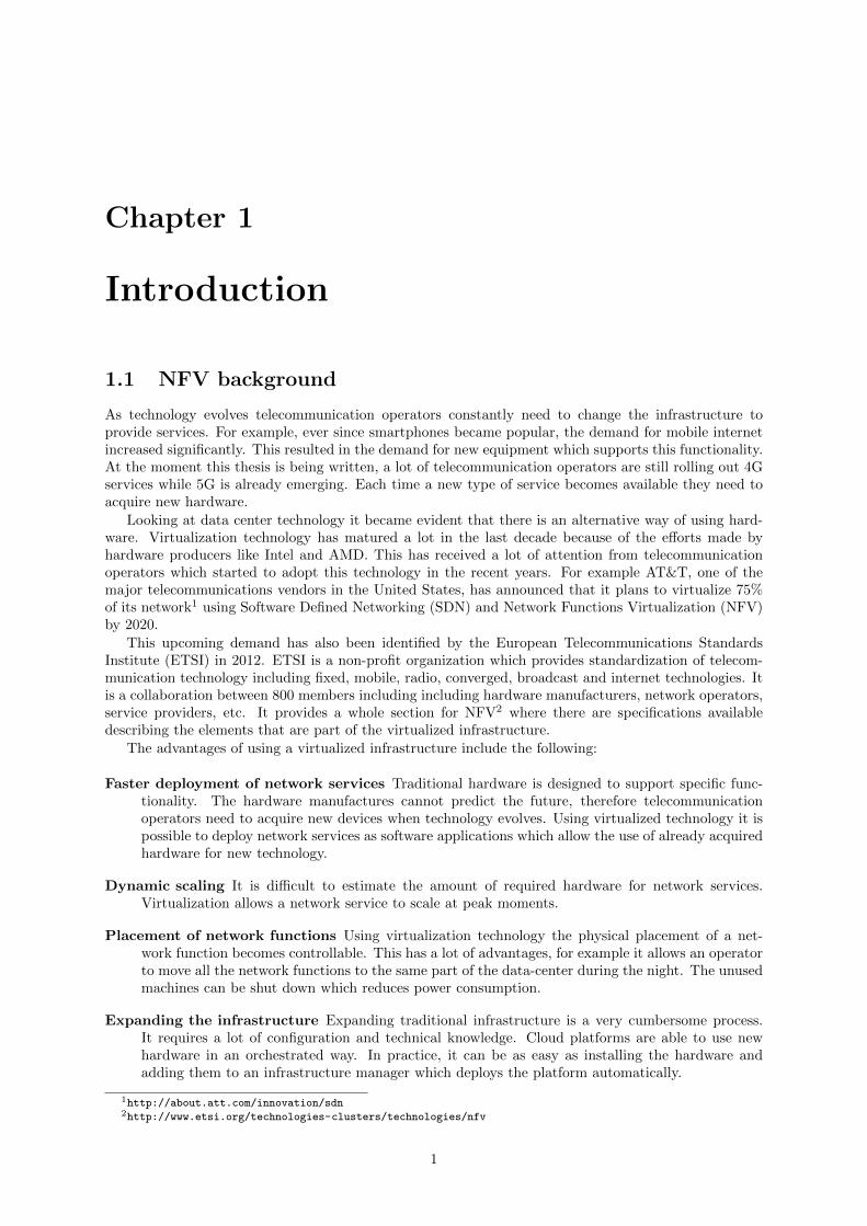
1.1 NFV background
As technology evolves telecommunication operators constantly need to change the infrastructure toprovide services. For example, ever since smartphones became popular, the demand for mobile internetincreased significantly. This resulted in the demand for new equipment which supports this functionality.At the moment this thesis is being written, a lot of telecommunication operators are still rolling out 4Gservices while 5G is already emerging. Each time a new type of service becomes available they need toacquire new hardware.
Looking at data center technology it became evident that there is an alternative way of using hard-ware. Virtualization technology has matured a lot in the last decade because of the efforts made byhardware producers like Intel and AMD. This has received a lot of attention from telecommunicationoperators which started to adopt this technology in the recent years. For example AT&T, one of themajor telecommunications vendors in the United States, has announced that it plans to virtualize 75%of its network1 using Software Defined Networking (SDN) and Network Functions Virtualization (NFV)by 2020.
This upcoming demand has also been identified by the European Telecommunications StandardsInstitute (ETSI) in 2012. ETSI is a non-profit organization which provides standardization of telecom-munication technology including fixed, mobile, radio, converged, broadcast and internet technologies. Itis a collaboration between 800 members including including hardware manufacturers, network operators,service providers, etc. It provides a whole section for NFV2 where there are specifications availabledescribing the elements that are part of the virtualized infrastructure.
The advantages of using a virtualized infrastructure include the following:
Faster deployment of network services Traditional hardware is designed to support specific func-tionality. The hardware manufactures cannot predict the future, therefore telecommunicationoperators need to acquire new devices when technology evolves. Using virtualized technology it ispossible to deploy network services as software applications which allow the use of already acquiredhardware for new technology.
Dynamic scaling It is difficult to estimate the amount of required hardware for network services.Virtualization allows a network service to scale at peak moments.
Placement of network functions Using virtualization technology the physical placement of a net-work function becomes controllable. This has a lot of advantages, for example it allows an operatorto move all the network functions to the same part of the data-center during the night. The unusedmachines can be shut down which reduces power consumption.
Expanding the infrastructure Expanding traditional infrastructure is a very cumbersome process.It requires a lot of configuration and technical knowledge. Cloud platforms are able to use newhardware in an orchestrated way. In practice, it can be as easy as installing the hardware andadding them to an infrastructure manager which deploys the platform automatically.
1http://about.att.com/innovation/sdn2http://www.etsi.org/technologies-clusters/technologies/nfv
1

Using a virtualized platform allows flexible placement of network functions. This requires a platformwhich manages the hardware resources. For traditional data centers there are already cloud platformsavailable. One of the most popular platforms is Openstack. It has therefore been the platform of choicefor the Open Platform for NFV project, also called OPNFV.
OPNFV is a collaborative project which aims to identify shortcomings of existing cloud technologyin the context of network services. It can be seen as a major collaboration between most of the bigtelecommunication companies and hardware providers to create a cloud platform for NFV. In practiceit provides extra capabilities to Openstack. It consists of a number of projects which provide a specificcapability. One of these projects, called Open vSwitch For NFV, is used in this thesis.
This thesis uses OPNFV Brahmaputra which doesn’t represent a full orchestrated cloud environ-ment but focuses on the part that manages the hardware resources, also called the Virtual InfrastructureManager (VIM). The goal is to create an open source cloud platform which can be integrated by telecom-munication providers into their orchestrator.
In February 2016 ETSI announced a new project which aims to provide a open source orchestrationplatform[1] called Open Source MANO (OSM). One of the solutions provided by OSM is called Open-MANO which can be used for certain orchestration functionality. At Mobile World Congress 2016 OSMhas successfully hosted a demonstration of a virtual network service using OpenMANO and Openstackas the virtual platform[12].
1.2 NFV data center
Data centers have become a very common concept in various environments. At the moment this thesis isbeing written these environments have proven to be very useful for application level services. Examplesof these are web hosting, eCommerce, big data, DBaaS, etc. These have a common property that theystore content for users, in other words the data-center owns the data. This property requires certaincharacteristics of the data center, for example they often have some kind of replication mechanism.
Telecommunication providers are concerned with providing communication channels between users.For example providing internet connectivity, providing mobile networks, etc. These communicationchannels often consists of a chain of services which together form an end-to-end service. In this kind ofenvironment the data center does not own data, but instead it is responsible for delivering it from pointA to B. This also means that they are mostly focused on L2, L3 and L4 of the networking stack insteadof the application layer. The requirements become different in the sense that it is more important toprovide fast and reliable communication channels than storing content. This introduces the concept ofNFV data centers which are specific for delivering network services.
To make optimal use of hardware in data centers, they use virtualization technology. The conceptof using virtualization in combination with many hardware resources is also called cloud computing. Inpractice this can been seen as a large pool of servers which acts as hosts where each host can run one ormultiple virtual machines. Each virtual machine requires a data path to the outside network, in otherwords between the network interface and the virtual machine.
The data path between the network interface and the virtual machine used in existing cloud platformsis not well suited for delivering network services. Therefore this data path needs to be optimized. Thisproblem can be solved in 2 ways, either by providing direct hardware access from the virtual machineor by using a virtual switch which is optimized. This thesis will compare 2 popular approaches whichare available today, it can therefore be classified as a comparative study : SR-IOV makes use of directhardware access and Open vSwitch with DPDK is a popular virtual switch which is enhanced to acceleratethe data path.
These 2 techniques will be compared using Openstack as the cloud platform. Openstack is an open-source platform which gets a lot of attention from NFV communities. It is the platform used by theOpen Platform for NFV community which provides a platform which is optimized for NFV use cases.
At the moment of writing this thesis Openstack is already used in telecommunication environments.One example is the integration with OpenMANO. In this environment the data path is optimized by al-lowing direct hardware access form the VM to the NIC, also called PCI passthrough[23]. PCI passthroughof the NIC has its own limitations which have led to the development of SR-IOV which can be combinedwith PCI-passthrough. SR-IOV is a hardware feature on the NIC which allows the NIC to be used asa L2 switch. This introduces multiple network interfaces in the OS which are called virtual functions.Each of these interfaces has its own MAC address.
Although SR-IOV overcomes the performance issues with NFV data path, there are still some short-comings. This has led to the demand for alternatives. One alternative is the use of an optimized
2

implementation of a virtual switch. Open vSwitch is a popular virtual switch which can be combinedwith a library called DPDK to achieve better performance. Since Open vSwitch is an open source project,it is a promising alternative to SR-IOV when using Openstack.
1.3 Research questions
This thesis has been combined with an internship with Intel as a part of a market development group.The goal of this group is to characterize Intel hardware which provides performance data. The mainquestion posed was the following: How can a virtualized environment (based on Openstack) be used bytelecommunication operators to deploy their network services? Openstack has already adopted featuresto improve support for NFV use cases, these are often referred to as Enhanced Platform Awareness(EPA)[10]. These features include PCI passthrough, SR-IOV and exposing hypervisor configurationoptions. Since there is a great demand for virtual switches OPNFV has initiated a project called OpenvSwitch for NFV. This project uses Open vSwitch with DPDK as a data plane accelerator. In contraryto PCI passthrough and SR-IOV, Open vSwitch with DPDK is in an experimental phase and not yetadopted by the Openstack community. This leads to the following questions which are clarified in thisthesis:
1. Why is it necessary to optimize the data path between the NIC and the VM?
2. Why is the current technology, SR-IOV with PCI passthrough, insufficient? Is an alternative reallynecessary?
3. Is Open vSwitch with DPDK a valid alternative? If so, what are the shortcomings?
1.4 Thesis structure
The structure of the thesis looks as follows. Chapter 2 describes the NFV framework defined by ETSI.This framework identifies the different components of an architecture for telecommunication providersfocused on virtualization. In chapter 3 the shortcomings of the native networking stack of a generalpurpose OS are discussed and alternatives are presented.
Chapter 4 and 5 discuss Openstack which is a cloud resource management platform. This platformcan be used to manage COTS hardware. The platform needs to be configured with a data path betweenthe NIC and the VM which is used for data plane packet processing. The different alternatives aredescribed in chapter 6.
Finally the different alternatives are evaluated and compared in chapter 7 and 8. In chapter 9 theresults are evaluated and discussed.
3

4

Chapter 2
NFV architectural framework
2.1 Introduction
Telecommunication operators need network services for various reasons. They are the core for providinginternet, cellphone are any kind of connectivity. They provide various functions such as security, usersubscribing, etc. These services require a high networking throughput and a low latency. To meet thesehigh demands, the network services are mostly provided as dedicated hardware appliances.
Although these appliances satisfy the demand for high performance, there are a number of downsides.The configuration is often vendor specific and requires trained personnel. If a network operator choosesappliances of a certain vendor, it is later hard to move to a different vendor. Most of the time theseappliances perform a single or a limited number of related functions which are programmed in the circuit.Therefore the operator needs to buy different appliances for different functions, and they can’t alwaysbe upgraded.
Because of their physical appearance, it is not trivial to insert or replace certain services. Besidesthe need for space and power it could also take a while before the services are in place. If there is asudden or temporary need for more services, the only choice is to add extra appliances in advance whichwould lead to unused infrastructure. Furthermore, the life cycle of these appliances keeps decreasing astechnology evolves.
These issues where also very common in other computer areas where the solution to this problem isprovided by hardware virtualization. Virtualization allows software to be isolated from the hardware,in most cases the whole operating system runs as a virtual instance or virtual machine (VM). The useof VMs has many benefits, it allows multiple operating systems to run on the same hardware deviceand it allows dynamic access to resources like processing power. Besides the benefits there are alsosome downsides, running an application or operating system as a virtual machine has a performancepenalty. Because of this penalty some processor manufacturers added support for virtualization on theirprocessors, for example Intel VT-x[38] and AMD-V.
To fully benefit from virtualization techniques a lot of companies started building data centers hostingthousands or even millions of computers. These data centers provide compute, networking and storageresources to a large amount of users. These resources can be accessed on demand, this allows the usersto launch new VMs without the need for new hardware and it allows software to be migrated to differentphysical devices. This concept of providing shared resources on demand is called cloud computing.
Cloud computing has been a well established solution for many years in different areas. To solve theproblem of manual configuration of network functions we can apply the concept of cloud computing tonetwork functions, this is called Network Functions Virtualization (NFV). NFV aims on deploying VirtualNetwork Functions (VNF) on standard high volume servers, switches and storage. This collection ofsoftware and hardware resources which build the environment for VNFs is called the NFV Infrastructure(NFVi).
The use of virtualization in a network deployments creates new challenges that where not present intraditional non-virtualized environments. The European Telecommunications Standards Institute (ETSI)has published an architectural framework that focuses on the aspects that are unique to virtualization[16] in a telecommunication network. This framework describes different functional blocks and theirinteraction through reference points. Different vendors can build their own functional blocks which canbe combined in a fully interoperable multi-party NFV solution.
Figure 2.1 shows the different elements which form a complete NFV solution. The three main domains
5

Figure 2.1: NFV reference framework as described by ETSI. The framework defines the different elementswhich can be implemented independent and accessed through their reference points.
are:
Virtualised Network Function: The goal of NFV is to move existing network functions on dedicatedhardware into a virtualized environment in software, these network functions are referred to asVNFs. A VNF can be a single component or a combination of multiple components, for exampleas a deployment over multiple VMs. Each VNF can be accompanied with a Element ManagementSystem (EMS) which can be used for configuration and monitoring.
NFV Infrastructure: The collection of hardware and software resources which build the environmentused for the deployment of VNFs is called the NFV infrastructure. This includes the computing,storage and network hardware resources and the abstraction layer which decouples the hardwarefrom software.
NFV Management and Orchestration: the virtualization specific management tasks are handledby NFV Management and Orchestration (NFV MANO). It is responsible for the management ofthe NFVi, the life cycle management of the VNFs and the orchestration of end-to-end services.
A telecommunications service provider will eventually need to offer end-to-end services to customersand create revenue. The Business Support Systems (BSS) refers to the applications which are responsiblefor customer facing activities. These include account management, billing, customer support, and servicemodification. On the other hand service providers need to make sure that the end-to-end services areprovisioned and maintained. The systems that are responsible for this are called Operations SupportSystems (OSS). Both systems work together to provide telecommunication services to the customers andare already present in traditional networks.
The different functional blocks in the architectural framework interact with each other through refer-ence points. These are called reference points since it exposes an external view of a functional block. Theexecution reference points deal with the hosting of VNFs and the virtualisation of hardware resources.This allows VNFs to be ported to other NFVi environments and it allows different underlying hardware.
6

Most of the reference points are between functional blocks in the NFV management and orchestrationdomain. These reference points are concerned with the management and operation of the network envi-ronment. The other (dotted) reference points are already present in current network environments andmight need extension for NFV.
2.2 NFV infrastructure
As mentioned before NFVi is defined by the collection of software and hardware resources which buildthe environment for VNFs. These resources can be placed on different locations where each locationis referred to as a NFVi Point of Presence (PoP). The hardware resources in a NFVi include compute,network and storage hardware which are abstracted by the virtualisation layer. The following domainsare identified by the ETSI NFV infrastructure overview[18]:
• Compute domain
• Hypervisor domain
• Network domain
Figure 2.2: Overview of the different NFVi domains identified by the ETSI NFV infrastructure overview.The hypervisor domain is concerned with the virtualization layer on top of the compute and storagehardware. The compute and storage hardware form the compute domain and the network domain isconcerned with networking devices and their virtualization capabilities, for example OpenFlow enabledswitches.
2.2.1 Compute domain
The main components in this domain are the servers and the storage devices. The servers which areresponsible for running the different VMs are also called compute nodes. The connection with the physicalpart of the network domain is provided by the NIC. More complex NICs may contain offload features orother acceleration features like SR-IOV. Chapter 6 gives a more detailed explanation of SR-IOV.
A lot of network functions need to hold some kind of state to function. A router for example has arouting table which is used for its functionality. The preferred characteristics for storage can be differentfor each VNF. The primary characteristics of storage devices are:
• Latency
• Capacity
• Volatility or persistence
A server has CPU registers, CPU cache and RAM which provide fast storage but usually don’t have avery high capacity and lose all its state when the device reboots. A larger and persistent form of storageis provided by Hard Disk Drives (HDD) which can be part of the server which hosts the VMs. This kindof storage is called Direct Attached Storage (DAS).
7

A HDD can also be placed in a separate storage device and provide storage to the compute nodesthrough a network channel. This can be done either by Network Attached Storage (NAS) or a StorageArea Network (SAN). NAS provides a file system which can be attached over the network. It typicallyprovides access to files using network file sharing protocols. A SAN provides storage at block-level whichcan be used to build a file system.
2.2.2 Hypervisor domain
The software layer which exposes the physical resources on a server as virtual resources is defined asthe hypervisor domain. The hypervisor itself allows multiple VMs to run on a single server. Runningan operating system as a VM often comes with a performance penalty. Some CPU instructions need tobe translated which introduces a context switch. Hardware vendors quickly saw the benefits of runningoperating systems as VMs and modified their products to improve performance. Intel VT-x and AMDAMD-V are two technologies which allow VMs to run on a server without the need for translated CPUinstructions. Another performance penalty is a consequence of sharing resources between multiple VMs.The host operating system can move virtual cores to different physical cores at any time which introducesa context switch.
Another major part of the hypervisor domain is the connection of VMs with each other and outsidethe host. The most straight-forward way to do this is to assign a device directly to the VM, this iscalled device pass-through. This limits the number of possible VMs to the number physical devices.To overcome this problem it is possible to use SR-IOV to create VFs which can be passed to the VM.This also limits the number of VMs, but it is possible to create much more VFs than it is to attachphysical devices. Another way of interconnecting VMs is by using a virtual switch. This switch willrun in software and is able to interconnect VMs with each other and with the NIC. More information isavailable in chapter 6.
2.2.3 Network domain
The network domain is responsible for the following communication channels:
• between the different components of a VNF.
• between VNFs.
• between the VNFs and their orchestration and management.
• between components of the NFVi and their orchestration and management.
To make optimal use of the network resources it is necessary to create virtual networks. This allowsus to use the same network infrastructure for different connections between VNF components. One wayof defining virtual networks is by using VLANs where each network is associated with a VLAN identifier.This identifier is limited to 4096 different virtual networks which is not sufficient in a data center context.Other techniques like VXLAN which support up to 16 million virtual networks can be used to overcomethis problem.
The Network domain will provide an interface to manage the physical network infrastructure whichcan be used by the VIM. SDN technologies like OpenFlow can be used for this purpose. For example,the NFVi can provide a centralized OpenFlow controller which is used to control OpenFlow enabledswitches. In this case OpenFlow is used to manage and control the network infrastructure. When a newVNF is inserted the OpenFlow controller will update the necessary devices. This approach provides agreat benefit to service providers since they only need to provide switches which can be controlled bythe OpenFlow protocol. This prevents vendor lock-in since OpenFlow is an open protocol. SDN andOpenFlow will be described in more detail in section 6.4.1.
2.3 NFV Management and Orchestration
A NFV environment exists of many devices with different functionalities. It is important that all thesedevices work together to create a network service which can be offered to the customer. The serviceprovider is most interested in delivering these services to the customer without manual configuration.This requires automating the different tasks which create and manage the network service. The collectionof these automated tasks is called orchestration.
8
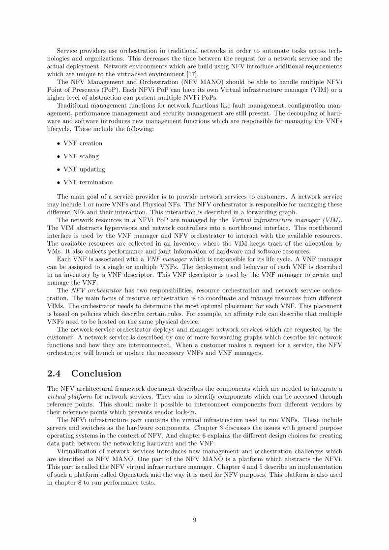
Service providers use orchestration in traditional networks in order to automate tasks across tech-nologies and organizations. This decreases the time between the request for a network service and theactual deployment. Network environments which are build using NFV introduce additional requirementswhich are unique to the virtualised environment [17].
The NFV Management and Orchestration (NFV MANO) should be able to handle multiple NFViPoint of Presences (PoP). Each NFVi PoP can have its own Virtual infrastructure manager (VIM) or ahigher level of abstraction can present multiple NVFi PoPs.
Traditional management functions for network functions like fault management, configuration man-agement, performance management and security management are still present. The decoupling of hard-ware and software introduces new management functions which are responsible for managing the VNFslifecycle. These include the following:
• VNF creation
• VNF scaling
• VNF updating
• VNF termination
The main goal of a service provider is to provide network services to customers. A network servicemay include 1 or more VNFs and Physical NFs. The NFV orchestrator is responsible for managing thesedifferent NFs and their interaction. This interaction is described in a forwarding graph.
The network resources in a NFVi PoP are managed by the Virtual infrastructure manager (VIM).The VIM abstracts hypervisors and network controllers into a northbound interface. This northboundinterface is used by the VNF manager and NFV orchestrator to interact with the available resources.The available resources are collected in an inventory where the VIM keeps track of the allocation byVMs. It also collects performance and fault information of hardware and software resources.
Each VNF is associated with a VNF manager which is responsible for its life cycle. A VNF managercan be assigned to a single or multiple VNFs. The deployment and behavior of each VNF is describedin an inventory by a VNF descriptor. This VNF descriptor is used by the VNF manager to create andmanage the VNF.
The NFV orchestrator has two responsibilities, resource orchestration and network service orches-tration. The main focus of resource orchestration is to coordinate and manage resources from differentVIMs. The orchestrator needs to determine the most optimal placement for each VNF. This placementis based on policies which describe certain rules. For example, an affinity rule can describe that multipleVNFs need to be hosted on the same physical device.
The network service orchestrator deploys and manages network services which are requested by thecustomer. A network service is described by one or more forwarding graphs which describe the networkfunctions and how they are interconnected. When a customer makes a request for a service, the NFVorchestrator will launch or update the necessary VNFs and VNF managers.
2.4 Conclusion
The NFV architectural framework document describes the components which are needed to integrate avirtual platform for network services. They aim to identify components which can be accessed throughreference points. This should make it possible to interconnect components from different vendors bytheir reference points which prevents vendor lock-in.
The NFVi infrastructure part contains the virtual infrastructure used to run VNFs. These includeservers and switches as the hardware components. Chapter 3 discusses the issues with general purposeoperating systems in the context of NFV. And chapter 6 explains the different design choices for creatingdata path between the networking hardware and the VNF.
Virtualization of network services introduces new management and orchestration challenges whichare identified as NFV MANO. One part of the NFV MANO is a platform which abstracts the NFVi.This part is called the NFV virtual infrastructure manager. Chapter 4 and 5 describe an implementationof such a platform called Openstack and the way it is used for NFV purposes. This platform is also usedin chapter 8 to run performance tests.
9

10
Chapter 3
Data-plane packet processing
3.1 Introduction
The transition from dedicated appliances into a virtualized environment requires commercial off-the-shelve (COTS) hardware. Instead of a single appliance for each network function, all network functionscan be placed on any device. This raises the question, can we use COTS hardware for high performancepacket processing?
COTS hardware is managed by an operating system (OS) which manages the different components.An OS allows multiple software applications to run on a single device. This chapter is concerned withthe performance issues which are raised when running NFV applications on a general purpose OS.
3.2 Fast packet processing
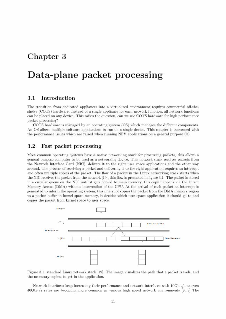
Most common operating systems have a native networking stack for processing packets, this allows ageneral purpose computer to be used as a networking device. This network stack receives packets fromthe Network Interface Card (NIC), delivers it to the right user space applications and the other wayaround. The process of receiving a packet and delivering it to the right application requires an interruptand often multiple copies of the packet. The flow of a packet in the Linux networking stack starts whenthe NIC receives the packet from the network [19], this flow is presented in figure 3.1. The packet is storedin a circular queue on the NIC until it gets copied to main memory, this copy happens via the DirectMemory Access (DMA) without intervention of the CPU. At the arrival of each packet an interrupt isgenerated to inform the operating system, this interrupt copies the packet from the DMA memory regionto a packet buffer in kernel space memory, it decides which user space application it should go to andcopies the packet from kernel space to user space.
Figure 3.1: standard Linux network stack [19]. The image visualizes the path that a packet travels, andthe necessary copies, to get in the application.
Network interfaces keep increasing their performance and network interfaces with 10Gbit/s or even40Gbit/s rates are becoming more common in various high speed network environments [8, 9] The
11

standard mechanism of handling packets in an operating system is not sufficient for handling packets atthese rates. A lot of CPU cycles are wasted on copying packets between memory regions with differentprivileges and the interrupt mechanism suffers from the interrupt livelock phenomenon [15]. In the lattercase the operating system spends most of its time handling interrupts instead of processing the packet.
A number of techniques have been suggested to deal with these issues [2]. In order to reduce thenumber of copies made we can use the zero-copy technique [36]. This technique reduces the number ofcopies by creating regions memory which are visible for both the NIC and the user space application,instead of copying the entire packet a pointer to the packet is passed to the application.
A lot of packet processing applications don’t need the entire networking stack, therefore it is oftenbeneficial to bypass the kernel and pass raw packets to the user space application. This allows theprogrammer to create applications that can be optimized for specific scenarios.
In order to avoid generating interrupts packets for single packets we can transfer multiple packets asa group to the application, this is called batching. To eliminate the overhead of interrupts altogether,the application can use a polling mechanism, in this case the application runs in an infinite loop where itconstantly checks if packets are available for processing. This should only be the case if the applicationneeds to handle packets of a 10Gbit/s NIC at line-rate, otherwise it is possible that a lot of CPU arewasted just looking for packets.
In next sections we will look at some frameworks [37] that have adopted these techniques to achievepacket processing at line-rate.
3.2.1 NAPI
As mentioned before the standard Linux networking stack suffers from livelock under heavy load. In thiscase a polling mechanism could be used to solve this problem but it would waste a lot of CPU cyclesunder light loads. NAPI provides an alternative interface for networking devices in the Linux kernelusing a hybrid approach to process packets [35]. Instead of generating an interrupt for each packet theNIC will generate a interrupt for the first packet in a batch. Next the NIC will periodically poll forremaining packets, if there are no packets left in the queue it will switch back to generating an interrupt.This reduces the overhead created by using the interrupt mechanism while avoiding wasted CPU cyclesunder light loads.
When the process starts the NIC is in a state where the polling mode is turned off and interrupts areenabled [34]. The first packet that arrives will generate an interrupt, this interrupt will move the NICto a new state where interrupts are disabled and polling is turned on. The packets that arrive in thepolling state are received in a DMA enabled region. At this point it is possible that the CPU is busyhandling other processes. When this is the case, the packets will stay in the DMA enabled region untilthey are processed.
When the CPU is scheduled handle the to the next packet in the ring it will be processed by thenetwork stack the same way as it would have been handled by an interrupt. This is repeated for all thepackets in the ring or until a certain amount of packets is handled. If all the packets are handled theNIC will move back to the state where polling is turned of and interrupts are enabled.
When the NIC is under heavy network load it will stay in polling mode and the CPU will be scheduledfrequently to handle the buffered packets. If there is not a lot of traffic, the NIC will mostly stay ininterrupt enabled mode. The main benefit of NAPI is a significant improvement of CPU utilization.
NAPI is part of the Linux kernel and can be turned on if necessary. It acts as an addition to theLinux network stack and thus allowing Linux to be used in more demanding network environments as apacket processing framework.
3.2.2 PF Ring
PF Ring improves packet processing by avoiding packet copies between kernel space and user space. Thisis achieved by creating a memory mapped packet buffer which is shared by the kernel and user spaceapplications. To achieve this goal, the NIC is bound to a new type of socket which has a circular bufferwhere the packets are copied on arrival. This buffer is allocated at the creation of the socket, this avoidsmemory allocation costs at the arrival of packets. When a packet arrives it is copied to the circular usinga DMA mechanism, at this point all the work is done by the kernel and the NIC. To copy packets fromthe NIC to the buffer it is possible to use NAPI as shown in figure 3.2.
When a user space application wants to read these packets it maps to the circular buffer using ammap() system call which returns a pointer. After the application reads the packet it updates the
12
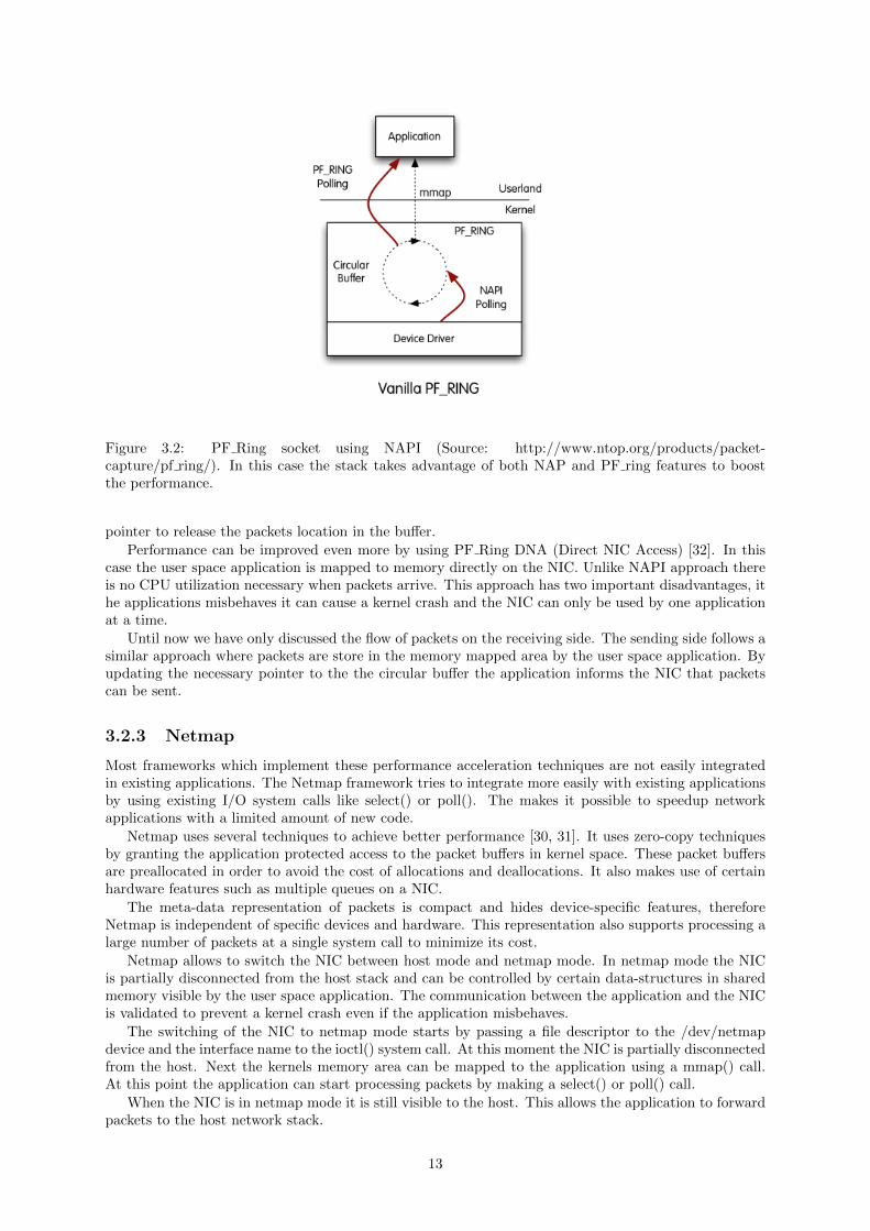
Figure 3.2: PF Ring socket using NAPI (Source: http://www.ntop.org/products/packet-capture/pf ring/). In this case the stack takes advantage of both NAP and PF ring features to boostthe performance.
pointer to release the packets location in the buffer.
Performance can be improved even more by using PF Ring DNA (Direct NIC Access) [32]. In thiscase the user space application is mapped to memory directly on the NIC. Unlike NAPI approach thereis no CPU utilization necessary when packets arrive. This approach has two important disadvantages, ithe applications misbehaves it can cause a kernel crash and the NIC can only be used by one applicationat a time.
Until now we have only discussed the flow of packets on the receiving side. The sending side follows asimilar approach where packets are store in the memory mapped area by the user space application. Byupdating the necessary pointer to the the circular buffer the application informs the NIC that packetscan be sent.
3.2.3 Netmap
Most frameworks which implement these performance acceleration techniques are not easily integratedin existing applications. The Netmap framework tries to integrate more easily with existing applicationsby using existing I/O system calls like select() or poll(). The makes it possible to speedup networkapplications with a limited amount of new code.
Netmap uses several techniques to achieve better performance [30, 31]. It uses zero-copy techniquesby granting the application protected access to the packet buffers in kernel space. These packet buffersare preallocated in order to avoid the cost of allocations and deallocations. It also makes use of certainhardware features such as multiple queues on a NIC.
The meta-data representation of packets is compact and hides device-specific features, thereforeNetmap is independent of specific devices and hardware. This representation also supports processing alarge number of packets at a single system call to minimize its cost.
Netmap allows to switch the NIC between host mode and netmap mode. In netmap mode the NICis partially disconnected from the host stack and can be controlled by certain data-structures in sharedmemory visible by the user space application. The communication between the application and the NICis validated to prevent a kernel crash even if the application misbehaves.
The switching of the NIC to netmap mode starts by passing a file descriptor to the /dev/netmapdevice and the interface name to the ioctl() system call. At this moment the NIC is partially disconnectedfrom the host. Next the kernels memory area can be mapped to the application using a mmap() call.At this point the application can start processing packets by making a select() or poll() call.
When the NIC is in netmap mode it is still visible to the host. This allows the application to forwardpackets to the host network stack.
13

3.2.4 PacketShader
A very different approach of improving performance is to process packets parallel on multiple cores.Graphical Processing Units (GPUs) often have hundreds or even thousands of cores originally used forgraphical applications. Today, GPUs are also used for more general applications which benefit from thehighly parallel computing capabilities. PacketShader takes advantage of GPUs to create a user spaceframework for fast packet processing [20].
Just as other frameworks PacketShader uses a modified technique for handling the reception andtransmission of packets via the NIC. To avoid per-packet memory allocations it preallocates a hugepacket buffer which holds fixed sized cells which can be reused. The transmission to and from the NIC isdone by DMA. The framework uses batch processing in different stages of the transmission. By mappingthe huge packet buffer to I/O memory it is possible for the NIC to transfer multiple packets at once.
Packets are also processed in batches at between kernel- and user space, this introduces a copy forbetter abstraction. To avoid the live-lock from interrupts PacketShader has implemented a mechanismwhich switches between interrupts and polling. This is similar to NAPI except that NAPI only works inkernel space memory.
Figure 3.3: PacketShader architecture [20]. The worker and master threads run on the CPU to runadministrative tasks, the master thread communicates with the GPU which executes the necessary work.
After the packets are transferred to the application into user space it is possible to use the GPUas a accelerator. Figure 3.3 shows the basic architecture. The framework uses CUDA as the API forprogramming the GPU. The CPU runs multiple threads to make optimal use of multi-core systems,these threads are divided in one master thread and multiple worker threads. The master thread is theonly thread that communicates with the GPU since the performance of CUDA degrades when multiplethreads access the same GPU. The worker threads are responsible for packet I/O.
The workflow is divided in three steps, pre-shading, shading and post-shading. The pre- and post-shading run on the worker threads, the shading step is handled by the master thread which communicateswith the GPU (Figure 3.4). Each worker thread fetches packets from receive queues. Malformed packetsare dropped and the normal packets are prepared for GPU processing. These packets are then transferredto GPU memory by the master thread. After they are done processing by the GPU the master threadstransfers the packets back to host memory into the output queue of the worker thread. This workerthread prepares the packets for transmission to the NIC.
Figure 3.4: PacketShader workflow [20]. There are multiple worker threads to pre- and post-process thepackets. The master delegates the actual work on the GPU.
14

3.2.5 Data Plane Development Kit
DPDK provides a set of libraries used to create data plane applications for high performance packetprocessing [6]. The set of libraries are available through an Environment Abstraction Layer (EAL),which allows access to hardware related resources.
The framework can use a run-to-completion model or a pipeline model for processing packets. Therun-to-completion model uses processing units which execute the same code on each packet. The pipelinemodel runs a different part of the functionality in each processing unit, each packet is processed by allthe processing units which are interconnected using lockless rings. Each model has its own advantagesand disadvantages, both models can be used in the same application as an hybrid approach.
Maximum performance is achieved by using optimization techniques which take the hardware intoaccount. Each CPU on a system with multiple CPU sockets has a different memory access time dependingon the memory location. The framework is aware of this and allocates memory close to each CPU, thisis called NUMA-awareness [22]. An alignment helper ensures that objects are evenly distributed acrossmemory channels to balance memory bandwidth utilization.
To avoid allocation- and deallocation costs for holding packets, memory is allocated by the MemoryPool Manager. This memory is allocated using huge pages to avoid Translation Lookaside Buffer (TLB)misses .
The framework uses a Poll Mode Driver to avoid the overhead of interrupts. Packets are transferredto the configured memory locations using Direct Memory Access, these memory locations are visible bythe user space application. After that the user space application receives the packets as a group andthey are moved around using pointers to their location.
Communication with the NIC and between different processing units in a pipeline is done by usinglockless rings. Traditional multi-core applications use locks to avoid race conditions when accessingshared objects. The use of locks introduces overhead because only one process can access a sharedobject at a time. To avoid using locks, shared objects can be passed by updating pointers using atomicoperations.
DPDK uses an open-source licensing model which allows anyone to use it. In this thesis DPDK willbe used to create Virtual Network Functions (VNFs) which will be used to test the performance of theNFV Infrastructure.
3.2.6 Comparison
Table 3.1 shows a comparison between the features supported by the different frameworks.
NAPI PF Ring Netmap PacketShader DPDKZero copy x x xPolling x x x x xBatch processing x x x x xPreallocated memory x x x xNUMA awareness x xHuge pages xGPU processing x
Table 3.1: Comparison between the features supported by different frameworks.
The main goal of these frameworks is to provide an interface to the NIC which allows packet processingat 10Gbit/s or more. Although their main goal is the same, they all take a different approach. NAPI andPF Ring provide a solution to a certain cause of the performance bottleneck. NAPI is focused on theoverhead caused by interrupts generated for each packet and PF Ring decreases the amount of packetcopies made. Both technologies can be combined or used separately.
Netmap tries to provide an alternative stable interface which is easy to adopt in existing application.Data Plane Development Kit on the other hand takes a more aggressive approach where each hardwarelimitation is optimized as best as possible. This requires a lot more consideration when writing anapplication and is more difficult to integrate in existing solutions.
To accelerate the processing step frameworks can benefit from multi-core systems. Most frameworksare able to use multiple CPU cores, but PacketShader goes a step further by using the highly parallelcomputing capabilities of GPUs.
15

3.3 Conclusion
Traditional network environments are build using dedicated appliances. These appliances lack flexibilityand configuration is often vendor-specific. An alternative to these appliances is the use of networkfunctions in software.
We described how general purpose computers can be used to process packets in high-performancenetwork environments. This required acceleration techniques which are applied in a number of frame-works. These frameworks are designed to handle traffic from 10Gbit/s NICs. Today, NICs with multiple10Gbit/s or 40Gbit/s ports are becoming more common [9, 8]. For example, the Intel XL710-QDA2 has2 40Gbit/s ports.
In the context of the internship with Intel, DPDK is used to run the tests in this thesis. Theframework originates as a proprietary product of Intel, but has been made open source. Because itheavily benefits from hardware features to achieve maximal performance it is the most suited frameworkto use on Intel hardware. In this thesis it is used in 2 ways:
In chapter 6 we explain how DPDK is used on the host OS to improve the performance of OpenvSwitch. This is concerned with the data transfer between the NIC and the VM and aims to achieve ahigher throughput and a lower latency. Using DPDK is not the default configuration of Open vSwitch,instead it uses the OS networking stack which suffers from the performance issues described in thischapter.
The DPDK frameworks is also used in chapter 7 to implement the applications that represent theVNFs. These applications run in the guest OS.
16

Chapter 4
Openstack
4.1 Introduction
Data centers often contain hundreds or thousands of servers to form a large pool of computing, networkingand storage hardware. By using virtualization techniques we can share these hardware resources amongmany different users without any interference from each other. To make optimal use of the hardware itis necessary that we see all these individual devices as one big pool of resources. This requires a platformthat controls all these devices. If a user wants to launch a new virtual machine, he doesn’t want to beconcerned about which machine it will be hosted on.
Figure 4.1: High level overview of the functionality provided by Openstack. (Source:https://www.openstack.org/software/)
Openstack provides a platform where multiple devices are managed using a web based dashboardor a REST API. This allows the user to launch a virtual machine, allocate storage and create virtualnetworks by just making a few clicks. The Openstack platform consists of multiple individual projects,also called services, which provide a specific functionality. The following are the core services:
Nova: is responsible for launching and managing virtual machines.
Glance: stores images containing operating systems which can be used by other services. An operatingsystem is normally stored on a disk volume which is part of a physical storage device. It is alsopossible to store a disk volume as single file, these files are called (disk) images.
Neutron: provides network components for other services, Nova depends on this service to provideconnectivity between virtual machines.
Keystone: provides authentication for other services.
Swift: is used to store objects such as documents, images, and so on.
Cinder: provides block storage which can be attached to virtual machines.
It is not necessary to use all available services although some depend on other services to function.For example, Nova depends on Glance to provide images for the creation of virtual machines. Next to
17

these core services there are also optional services1 available which can be used to provide additionalfunctionality.
Each device in an Openstack network is referred to as a node. The administrator can assign differentroles to different nodes. This role defines the functionality that is provided by that device. The mostcommon types of nodes are the following:
Controller node: this node is used for managing all other nodes in the deployment and it exposes aninterface to the users on which they can manage their virtual machines.
Compute node: hosts the virtual machines.
Networking node: acts as a gateway between the virtual instances and the internet and runs networkfunctions like routers, DHCP servers, load balancers, ...
Storage node: provides storage that can be attached to the virtual instances.
The nodes in a Openstack deployment are connected to multiple networks. One of these networksis used to send messages, copy virtual machines, and so on. This network is called the managementnetwork and is only used for administrative purposes, virtual machines will never send traffic on thisnetwork. Other networks are used to provided connectivity to the internet and between the VMs and soon.
The administrator can limit the amount of virtual machines that can be used by users. This is doneby the creation of tenants, also called projects. Each tenant has a certain limit of virtual resources, forexample a maximum number of CPUs, RAM, and so on. Multiple users can be part a tenant and a usercan be part of multiple tenants.
Chapter 5 describes the potential role of Openstack in the NFV architectural framework. It alsodescribes in how it should be configured to be able handle NFV workloads.
4.2 Nova
To launch a virtual machine, Openstack needs to choose the most suited device and control the hypervisoron that device, this is handled by the service called Nova. Nova supports multiple hypervisors:
KVM: Kernel-based Virtual Machine is a hypervisor that is part of the Linux kernel and makes use ofvirtualization extensions like Intel VT or AMD-V for near-native performance.
Xen: is a popular open source hypervisor which supports different types of virtualization. Just like KVMit can provide virtualization which uses hardware features to improve performance. It is also able touse a different approach to virtualization where the guest operating system is modified to optimizethe communication with the hypervisor. This type of virtualization is called paravirtualization.
VMware vSphere: collection of hardware virtualization products from VMWare including a hypervi-sor.
Hyper-V: hypervisor developed by Microsoft which uses hardware virtualization support.
LXC: Linux Containers are lightweight virtual machines. Instead of virtualizing an entire operatingsystem we can use isolation techniques to separate part of the operating system. In this case theuser sees this isolated part as a single operating system or a virtual instance.
QEMU: Quick EMUlator uses emulation techniques to virtualize hardware. It has a significant lowerperformance than hardware-assisted hypervisors and is only used for development purpose.
UML: User Mode Linux allows guest operating systems to run as a user space application. Just asQEMU it has a low performance and is mostly used for development purpose.
To be able to boot a virtual machine Nova needs a disk image which contains the OS. These diskimages are provided by Glance. Whenever Nova wants to boot a VM it requests the correct image.The VMs can be customized at creation using the cloud-init program. This program should already beinstalled on the image.
1http://www.openstack.org/software/
18

The cloud-init program is used by Nova for various reasons. For example, Nova uses it to insert aRSA public key into the VM which allows the user make an SSH connection to the VM without usinga password. It is also possible to run a custom script at creation. This can be used to install certainservices when the VM is created. For example the installation of an Apache web server.
When a VM is created the user needs to specify the properties it needs. For example the numberof CPUs, the amount of RAM and the disk space. These properties are defined by Nova flavors. Foreach VM the user wants to start he has to provide a flavor. Flavors can also be used to request certainfeatures from the host. For example certain capabilities from the CPU.
When a user launches a VM, Nova needs to decide which is the most suitable physical device at thatmoment. This decision is made by the Nova scheduler. By default the filter scheduler is used whichtakes 2 steps to launch a virtual machine. First it filters all the hosts that do not meet the criteria, thenit will decide the most appropriate candidate using weights (Figure 4.2).
Figure 4.2: Filtering and weighting process when launching a virtual machine using the filter scheduler.(Source: http://docs.openstack.org/kilo/config-reference/content/section compute-scheduler.html)
The administrator chooses the appropriate filters for his deployment. By default the following arefilters are used:
RetryFilter: if the scheduler sends a request to a host and the host fails to respond, this filter willprevent the scheduler from retrying a request to this host.
AvailabilityZoneFilter: it is possible to group physical hosts in availability zones, this filter filters outall the hosts that do not belong to the requested availability zone.
RamFilter: this filter prevents the scheduler from launching virtual machines on hosts that alreadyhave all their physical RAM consumed.
ComputeFilter: selects all hosts that are enabled and available.
ComputeCapabilitiesFilter: if the hosts makes a request for certain CPU properties, this filter willselect all hosts that satisfy these properties.
ImagePropertiesFilter: cloud images can have properties defined like architecture, hypervisor type,hypervisor version, and virtual machine mode. This filter passes all the hosts that can supportthese properties.
ServerGroupAffinityFilter: it is possible to group virtual instances together as a server group. Thisfilter will try to schedule the virtual machines that belong to the same group on the same host.
19

ServerGroupAntiAffinityFilter: in some cases it is preferable that virtual machines are launched ondifferent hosts. This filter will select only hosts that do not run an instance belonging to the sameserver group.
These are just the default filters that are enabled in Openstack, there are more filters available andit is possible to create your own filters. All hosts that pass these filters are weighted to be able to selectthe most suitable host. Every time an instances is launched on a host it will affect its weight.
4.3 Neutron
Openstack allows user to create a logical network topology on top of the physical infrastructure. To createthis topology Neutron allows you to create virtual networks and network functions. Neutron can be usedto create 2 types of networks: provider networks and tenant networks (Figure 4.3). Provider networksmap to the physical network in the data center, this allows Openstack objects to communicate withthe physical devices like routers to provide internet access. Tenant networks allow network connectivitybetween virtual machines and network functions that belong to the same virtual networks. Openstacksupports a number of network virtualization techniques to create virtual networks, In this way, thenetworks belonging to different tenants are completely isolated.
Figure 4.3: Different network types in an Openstack deployment. The tenant networks provide con-nectivity between VMs and virtual routers. The provider network is connected to internet. (Source:http://docs.openstack.org/liberty/networking-guide/intro-os-networking-overview.html)
Neutron provides the following network types and virtualization techniques:
Flat: when using a flat network type there is no network virtualization used, this is often the case forthe provider network which is connected to the internet.
VLAN: when using VLANs, each virtual network is associated with a VLAN ID. When this networkingtype used, each node is connected with the switch using a VLAN trunk connection where all trafficis tagged with a 802.1Q header. In this way multiple virtual networks can be created using a singleconnection with a node. It also allows virtual machines to communicate with physical devices thatare connected on a port belonging to the same VLAN.
GRE and VXLAN: GRE and VXLAN are encapsulation protocols that encapsulate each packet insidea new UDP packet. The connection between 2 instances is called a network tunnel. This requiresa router that is also connected with a provider network in order to communicate with physicaldevices.
Openstack has many different possible ways of deployment. The most basic scenario uses a networknode to provide connectivity to the external network for the virtual machines. This external network canonly be configured by the network administrator. Users are able to create tenant networks to provideconnectivity between virtual machines, routers and all kind of network services. Each virtual machine isconnected to a software switch. The default configuration uses Open vSwitch2. Users are able to connectthese virtual machines on a tenant network using private IP addresses. Neutron refers to these privateIP addresses as fixed addresses.
2http://openvswitch.org/
20

To provide internet connectivity on the virtual machines administrators can create virtual routers onthe network node. These routers use SNAT to provide internet connectivity using the routers externalIP address. They also use DNAT to be able to bind external IP address to virtual instances. Data centerproviders usually have a range of public IP addresses available, these IP addresses can be used by theusers to provide external connectivity to virtual instances. These external IP addresses are referred toas floating IP addresses. Besides connectivity to the external network, these routers also forward trafficbetween different tenant networks. Neutron also provides other network services like DHCP, firewalls,load balancers, ...
Figure 4.4 shows a scenario where a virtual machine is connected to the internet. In this scenario itis possible to create tenant networks using one of the 2 available virtualization techniques, either VLANsor VXLAN tunnels. Each compute node has 2 NICs which are used for traffic on the tenant networks.The network node has 3 NICs, 2 for the tenant networks and 1 for the external network. The tenantnetworks are connected to the external network using a virtual router in the network node.
Figure 4.4: Traffic flow from a virtual machine (instance) to the internet. (Source:http://docs.openstack.org/liberty/networking-guide/scenario-classic-ovs.html)
All the traffic from the virtual instance to the internet follows these steps on the compute node:
1. the virtual machine forwards the traffic to the Linux bridge qbr. This bridge is connected to afirewall which filters all the traffic that is sent and received by the virtual machine.
2. the bridge qbr forwards the traffic to the OVS Integration bridge br-int, this bridge knows to whichtenant network the port is connected to. Each virtual network is associated with a internal VLAN
21
tag, depending on the type of network, the traffic is either forwarded to the Tunnel bridge or theVLAN bridge.
3. For the tunnel network:
(a) The integration bridge forwards the traffic to the Tunnel bridge.
(b) The traffic is encapsulated in a UPD packet and tagged with the ID of the tenant network.
(c) The encapsulated traffic is sent into the physical network to the network node.
For the VLAN network:
(a) The integration bridge forwards the traffic to the VLAN bridge.
(b) The traffic is tagged with ID of the tenant network using a 802.1Q header.
(c) The tagged traffic is sent into the physical network to the network node. Using this type ofnetwork each node needs to be connected to the same sub-net and the physical infrastructureneeds to be able to handle VLAN traffic.
When the traffic arrives on the network node, these steps are followed:
1. For the tunnel network:
(a) The encapsulated traffic arrives on the Tunnel bridge.
(b) The Tunnel bridge replaces the VXLAN tag with an internal VLAN tag.
(c) The traffic is forwarded to the integration bridge.
For the VLAN network:
(a) The tagged traffic arrives on the VLAN bridge.
(b) The VLAN tag is replaced with the internal VLAN tag.
(c) The traffic is forwarded to the internal bridge.
2. The internal bridge forwards the traffic to the Router Namespace, this represents a virtual routerusing the Linux network stack. The traffic is translated to the external IP address using SNAT.
3. The traffic is forwarded tot the integration bridge which forwards it further to the External bridgewhere it eventually is forwarded to the internet.
This is the most basic deployment scenario which can be used to provide network connectivity. Themajor downside of this scenario is that all the traffic that is sent to a different network has to passthe network node, this limits the scalability of the network and it creates a single point of failure. Toovercome these issues, more complex deployment scenarios are possible.
Distribute Virtual Routing is an extension of this basic scenario where part of the router functionalitywill be provided directly on the compute nodes. This requires an extra NIC port on each compute node.In this scenario, a big part of the traffic is forwarded directly to the correct compute node without passingthe network node.
Another possible extension of the basic scenario is a scenario using the Neutron Virtual RouterRedundancy Protocol. The major goal of this scenario is to distribute network functionality on multiplenetwork nodes to avoid a single point of failure.
It is also possible to use the physical infrastructure for all the network functionality including tenantnetworks. This scenario maps the virtual networks to the physical networks which are referred to asprovider networks, In this case the external connectivity is provided by a physical router.
4.4 Other services
Nova and Neutron are the most important Openstack services which we will be using in this thesis.Openstack has a lot of services which provide a certain functionality. In the following sections we willdescribe some services which we will use. Besides these there are still much more services.
Openstack provides a web interface called Horizon in order to configure the platform and for usersto manage their available resources. Figure 4.5 shows the overview page where the usage the resources is
22
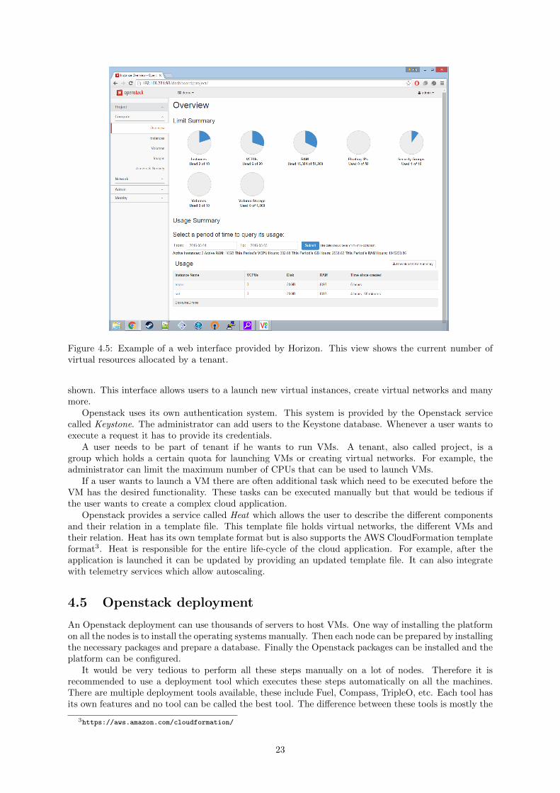
Figure 4.5: Example of a web interface provided by Horizon. This view shows the current number ofvirtual resources allocated by a tenant.
shown. This interface allows users to a launch new virtual instances, create virtual networks and manymore.
Openstack uses its own authentication system. This system is provided by the Openstack servicecalled Keystone. The administrator can add users to the Keystone database. Whenever a user wants toexecute a request it has to provide its credentials.
A user needs to be part of tenant if he wants to run VMs. A tenant, also called project, is agroup which holds a certain quota for launching VMs or creating virtual networks. For example, theadministrator can limit the maximum number of CPUs that can be used to launch VMs.
If a user wants to launch a VM there are often additional task which need to be executed before theVM has the desired functionality. These tasks can be executed manually but that would be tedious ifthe user wants to create a complex cloud application.
Openstack provides a service called Heat which allows the user to describe the different componentsand their relation in a template file. This template file holds virtual networks, the different VMs andtheir relation. Heat has its own template format but is also supports the AWS CloudFormation templateformat3. Heat is responsible for the entire life-cycle of the cloud application. For example, after theapplication is launched it can be updated by providing an updated template file. It can also integratewith telemetry services which allow autoscaling.
4.5 Openstack deployment
An Openstack deployment can use thousands of servers to host VMs. One way of installing the platformon all the nodes is to install the operating systems manually. Then each node can be prepared by installingthe necessary packages and prepare a database. Finally the Openstack packages can be installed and theplatform can be configured.
It would be very tedious to perform all these steps manually on a lot of nodes. Therefore it isrecommended to use a deployment tool which executes these steps automatically on all the machines.There are multiple deployment tools available, these include Fuel, Compass, TripleO, etc. Each tool hasits own features and no tool can be called the best tool. The difference between these tools is mostly the
3https://aws.amazon.com/cloudformation/
23
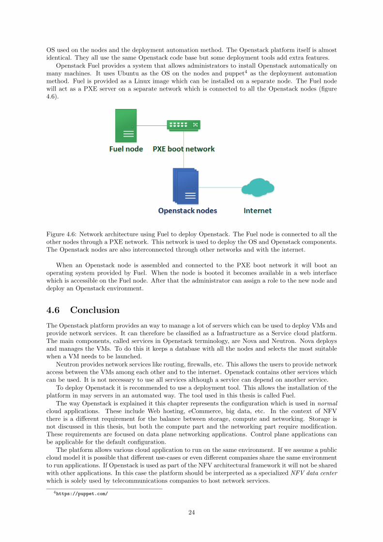
OS used on the nodes and the deployment automation method. The Openstack platform itself is almostidentical. They all use the same Openstack code base but some deployment tools add extra features.
Openstack Fuel provides a system that allows administrators to install Openstack automatically onmany machines. It uses Ubuntu as the OS on the nodes and puppet4 as the deployment automationmethod. Fuel is provided as a Linux image which can be installed on a separate node. The Fuel nodewill act as a PXE server on a separate network which is connected to all the Openstack nodes (figure4.6).
Figure 4.6: Network architecture using Fuel to deploy Openstack. The Fuel node is connected to all theother nodes through a PXE network. This network is used to deploy the OS and Openstack components.The Openstack nodes are also interconnected through other networks and with the internet.
When an Openstack node is assembled and connected to the PXE boot network it will boot anoperating system provided by Fuel. When the node is booted it becomes available in a web interfacewhich is accessible on the Fuel node. After that the administrator can assign a role to the new node anddeploy an Openstack environment.
4.6 Conclusion
The Openstack platform provides an way to manage a lot of servers which can be used to deploy VMs andprovide network services. It can therefore be classified as a Infrastructure as a Service cloud platform.The main components, called services in Openstack terminology, are Nova and Neutron. Nova deploysand manages the VMs. To do this it keeps a database with all the nodes and selects the most suitablewhen a VM needs to be launched.
Neutron provides network services like routing, firewalls, etc. This allows the users to provide networkaccess between the VMs among each other and to the internet. Openstack contains other services whichcan be used. It is not necessary to use all services although a service can depend on another service.
To deploy Openstack it is recommended to use a deployment tool. This allows the installation of theplatform in may servers in an automated way. The tool used in this thesis is called Fuel.
The way Openstack is explained it this chapter represents the configuration which is used in normalcloud applications. These include Web hosting, eCommerce, big data, etc. In the context of NFVthere is a different requirement for the balance between storage, compute and networking. Storage isnot discussed in this thesis, but both the compute part and the networking part require modification.These requirements are focused on data plane networking applications. Control plane applications canbe applicable for the default configuration.
The platform allows various cloud application to run on the same environment. If we assume a publiccloud model it is possible that different use-cases or even different companies share the same environmentto run applications. If Openstack is used as part of the NFV architectural framework it will not be sharedwith other applications. In this case the platform should be interpreted as a specialized NFV data centerwhich is solely used by telecommunications companies to host network services.
4https://puppet.com/
24

Chapter 5 explains how Openstack can be used as a part of the NFV architectural framework. In thisway the underlying hardware specifics are abstracted for components that are concerned with deployingnetwork services.
25

26

Chapter 5
Openstack as NFV virtualinfrastructure manager
5.1 Introduction
NFV makes use of multiple virtualised hardware resources to run networking functions. Openstack canbe used to manage these resources and fulfill the role of virtual infrastructure manager (Figure 5.1). Atfirst sight it seems as simple as just taking Openstack and use it to launch VNFs. But the overhead thatis involved when using virtualization has much more impact in a NFV context. Therefore it is necessaryto tune certain aspects of the platform for better performance.
Figure 5.1: Role of Openstack in the NFV architectural framework. The platform provides an interfacewhich can be used by the VNF manager and NFV orchestrator to run network services.
Since the loss of a single packet can have a significant impact in the delay of the upper lying protocolsit is useful prevent packet loss at all time. When sending 64 bytes packets at line rate on a 10Gbit/s
27

NIC, each packet needs to be processed in 67.2 microseconds. Therefore even very small interruptionscan cause a packet to be dropped.
When using general purpose hardware it becomes much more challenging to prevent packet loss.Most operating systems are designed to run multiple tasks and are therefore able to handle interrupts.It becomes even more complex when running the network functions in a VM. In this case both the hostand the guest OS can get interrupts which are able to disrupt the packet processing application. Theseproperties can mostly be overcome by configuration.
To minimize the chance for packet loss it is necessary to configure the system to handle interrupts onCPU cores which are not assigned for packet processing. It is also necessary to configure the hypervisorin a way that the VM can request certain performance optimization features.
5.2 Hypervisor configuration
By default Openstack uses QEMU as a hypervisor. To get the maximum performance the hypervisorneeds to be able to use hardware virtualization extensions like Intel VT-x. Therefore it is recommendedto use the KVM hypervisor. KVM is a fork of the QEMU project with the goal of getting the bestpossible performance. It requires a CPU with hardware virtualization extension, otherwise it falls backon QEMU. Both hypervisors are supported by Openstack and it is up to the administrator to choose themost suitable.
In the case of NFV it is highly recommended to use KVM. Since the cost of losing packets is veryhigh it is necessary to expose certain performance optimization features to the VMs. These features canbe requested in 2 ways, either by adding properties to the Nova flavor used to launch a VM or addingproperties to the Glance image.
When a VM is launched, by default the CPU topology is not exposed to the VM. For example, when 6cores are requested these are chosen at random in the host and these are presented to the VM as individualCPU sockets. It is recommended to expose the CPU topology in the VM. For example, a VM can belaunched with the following properties: ”hw:cpu sockets=2”, ”hw:cpu cores=4” and ”hw:cpu threads=2”.This exposes a total of 16 cores which are exposed as 2 CPU sockets with 4 hyperthreaded cores to theVM. The VNF may use this information to improve performance[26].
When running a DPDK application in a VM it needs huge pages to achieve the best possible per-formance. The compute node can be configured to assign part of the memory as 1GB huge pages.When huge pages are available they can be requested by the user by setting the ”hw:mem page size”:”1048576” property.
By default a virtual CPU core is dynamically assigned to a physical CPU core. This means that thehypervisor can decide to move the virtual core to a different physical core at any time. The migrationto a different core can not be predicted and causes packet loss. It is also possible to assign more virtualcores on a compute node than the number of physical cores. In this case physical cores are shared byvirtual cores. By setting the ”hw:cpu policy”: ”dedicated” property the hypervisor will map each virtualcore to a single physical core. This prevents the virtual core to be migrated and physical cores cannotbe shared.
Some server boards have multiple CPU sockets. With most of these architectures PCI devices andRAM memory have a different access time from each CPU socket. Each PCI bus and memory channelis connected to one socket. When a CPU tries to access a device attached to a different socket it hasto use a special connection between these sockets. One example of such a connection is Intel QuickPathInterconnect (QPI). This asymmetric design is called Non-uniform memory access (NUMA) where eachsocket with its devices is called a NUMA node. DPDK based applications can take this architecture intoaccount to get optimal performance.
By default Openstack assigns any available core or memory region to a VM. The VM doesn’t knowto which NUMA node each CPU, memory region or PCI device belongs. The user can configure theNUMA location of each CPU core location and memory region. By setting the ”hw:numa nodes”: ”2”property a certain number of NUMA nodes can be requested. This requires a compute node with at leastthis amount of NUMA nodes. Next the amount of memory for each node can be configured by setting”hw:numa mem.0”: ”4096” and ”hw:numa mem.1”: ”2048” properties, in this case 4GB of memory isrequested for node 0 and 2GB of memory for node 1. Also the NUMA node for each virtual core can beconfigured by setting the ”hw:numa cpus.0”: ”0-1” and ”hw:numa cpus.1”: ”2-5” property, in this casethe first 2 cores are requested for node 0 and the last 4 cores for node 1.
28

5.3 QEMU iothread interrupts
When a VM is launched using Openstack it creates a new QEMU process based on the given configuration.The architecture of this process uses a multi-threaded model to benefit from the multi-core CPU (figure5.2). There is distinction between vcpu threads and iothreads. For each CPU core in the guest a vcputhread is spawned, the host can schedule each thread on a different CPU core to maximize parallelism.
Figure 5.2: High level architecture of KVM. The hypervisor uses iothreads to emu-late hardware. (Source: http://events.linuxfoundation.org/sites/events/files/slides/
CloudOpen2013_Khoa_Huynh_v3.pdf)
Besides the vcpu threads there is also an iothread which handles an event loop1. This event loopswaits for events generated by file descriptors and timers which expire. In some cases the events loopscan spawn a worker thread for specific tasks.
If the VM is configured to use core pinning, then the vpcu threads and the iothreads have a differentcore affinity. Each vcpu thread is affinitized to a different physical CPU, but the iothreads and theworkers are affinitized to use all the cores used by the vcpu threads. In other words the core mask of theiothread is the same as that of the core masks of all the vcpu threads combined.
If there is no activity on the iothread, this has no influence on the vcpu threads. But during theexecution of the tests there was some activity on the iothreads which interrupted a vcpu thread for anexceptional long time. This behavior has not been observed when a VM was launched using the QEMUcommand line tool directly.
It is highly undesirable to have large interrupts in the guest OS. If the guest OS is processing packetsof 64 bytes at 10Gbit/s it can theoretically process 14880952 packets per second. If the system isinterrupted for 1 microsecond this would mean that it has to buffer at least 15 packets to prevent packetloss.
When running test cases which use a lot of cores for packet processing there was a lot of variation inthe results after the tests where repeated. After further investigation it became clear that one core wasinterrupted for an unusual long amount of time. To prevent these interrupts from occurring on the vcputhreads we used the taskset command to affinitize the iothreads on different cores.
1http://blog.vmsplice.net/2011/03/qemu-internals-overall-architecture-and.html
29

Figure 5.3: Duration of all the interrupts on core 12 in the guest OS. Core 12 has been identified asthe core where the iothread is scheduled, this is an arbitrary number and can be different in anotherconfiguration.
Figure 5.3 shows the duration of all the interrupts for a period of more than 6 minutes when theiothreads are scheduled on the same care as vcpu 12 and when the iothreads are scheduled on a differentcore. With the iothread and vcpu thread on the same care we observe 4 interrupts with a length of morethan 5 milliseconds.
avg (s) largest (s)With iothread 45,7 16672Without iothread 18,0 229
Table 5.1: Average and maximum length of the interrupts measured in figure 5.3.
Table 5.1 shows the average and maximum duration of the interrupts in figure 5.3. The largestinterrupts is more than 16 milliseconds, when processing packets at 10Gbit/s this would require a buffer of248095 packets to avoid packet loss. The buffers in a DPDK based application achieve better performancewhen they are small[25]. Therefore it is better to affinitize the iothreads to cores which are not used forpacket processing.
Nova uses a tool called libvirt to launch and manage VMs. Libvirt translates the given configurationto a qemu command line which runs the VM. Although there is a configuration parameter available inlibvirt to pin iothreads to certain CPUs on the host2, this is not exposed to Nova. At the time this thesisis written there is no indication that it will be exposed in the near future. The reason is probably tokeep generality since other hypervisors may not have similar configuration options.
5.4 Integration with OpenMANO
The goal of a platform like Openstack in a NFV context is to manage the resources and expose an APIthat hides low level details. The API that is exposed can be used by a NFV Orchestrator to createend-to-end network services. One example of such an NFV Orchestrator is OpenMANO.
OpenMANO is a Management and Orchestration implementation created by Telefonica which hasbeen published under an open source license. The architecture is based on the NFV ArchitecturalFramework[16] and consists of 3 main components:
• openvim
• openmano
• openmano-gui
2https://libvirt.org/formatdomain.html#elementsCPUTuning
30

Figure 5.4: High level overview of the interaction between the different OpenMANO components. TheOpenMANO components are based on the MANO part of the NFV reference architecture. The Externalcomponents part represent the NFVi.(Source: https://github.com/nfvlabs/openmano/blob/master/images/openmano-architecture.png)
Figure 5.4 shows how these components interact with each other. It is not necessary to all thecomponents, for example openmano-gui is not necessary and openvim can be replaced by Openstack. Itis also possible to use multiple VIMs which can be used to create end-to-end network services that gothrough more than 1 VIM.
To use Openstack it is necessary to add a plugin which allows Neutron to interact with the Open-Flow switch which is used by the dataplane interfaces. It is also necessary to expose the hypervisorconfiguration features described in section 5.2.
The openmano component provides an API based on REST which can be used to interact. This APIallows the deployment and management of VNF- and NS descriptors in the form of templates which canbe used to instantiate network services. The openmano-gui component interacts with this API, but it isalso possible to integrate into an OSS/BSS.
5.4.1 VNF Descriptors
A VNF descriptor describes a software based network function which can be deployed as part of anetwork service. The descriptor is stored by the openmano component in the form of a template writtenin YAML. A VNF descriptor contains the following components:
name Unique name of the VNF
description High level description
external-connections List of connections which can be used by other VNFs or networks.
internal-connections List of connections which can be used by VNF components to interconnect. Thiscomponent is only required if the VNF consists of multiple VMs.
VNF Components List of VMs which are part of the VNF.
31

Figure 5.5: Example of a VNF descriptor in openmano. The descriptor describes the connections andhardware requirements for each VNF component.
Figure 5.5 shows an example of a VNF with 1 VM, 1 management interface and 4 data plane interfaces.This VNF is very similar to the VNF used to compare the data path in this thesis. The VNFC sectionshows a single VM which is used to process packets. This section contains a list of NUMA nodes and foreach NUMA node the number of cores and the amount of memory which is requested. For this descriptorit is necessary to have compute nodes available which have exposed the hypervisor configuration featuresdescribed in section 5.2.
The connections to this VNF are visible in figure 5.6. The 4 connections named xe0-3 are used forpacket processing. The management interface name eth0 can be connected to a VNF manager whichhandles FCAPS functionality.
Figure 5.6: Visual representation of the VNF descriptor in figure 5.5. The blue connections rep-resent data plane traffic which require PCI passthrough and/or SR-IOV. The green connectionis a control plane connection which can be done using an unmodified virtual switch. (Source:https://github.com/nfvlabs/openmano/blob/master/images/descriptors/example-dataplanevnf1.png)
32

5.4.2 NS Descriptors
Figure 5.7 shows an example of a Network Service (NS) descriptor. It has a name and description whichare similar to the VNF descriptor. It also has a topology part where it describes the necessary nodeswhich are VNFs and networks that are already stored in the database.
Figure 5.7: Example of a NS descriptor in openmano. This descriptor describes the topology of theVNFs in used by the network service.
5.5 Conclusion
Openstack can fulfill the role of the virtual infrastructure manager in the NFV architectural framework.This allows the VNF manager and NFV orchestrator to interact with an API that abstracts low leveldetails which can be different on various environments. NFV applications are often very performancesensitive, therefore it is necessary to expose certain features from the hypervisor. These features includeexposing the underlying CPU topology, enabling huge pages, allowing to pin vcpus and exposing theNUMA topology.
Even with these features enabled there is still a chance of getting interrupts from QEMU iothreads.To avoid these interrupts it is necessary to affinitize the iothreads to CPU cores on the host which arenot used by the VM for packet processing. This cannot be done with Openstack at the moment.
At the time when this thesis is being written Openstack is already being used in MANO platforms likeOpenMANO. OpenMANO has its own VIM implementation but can also use Openstack. It requires PCIpassthrough, if necessary with SR-IOV, to run data plane traffic. The network infrastructure describedin chapter 4 is still used for control plane traffic.
Although PCI passthrough improves the performance a lot, it is not aligned with the cloud model.The cloud principle states that the VM is totally unaware of the underlying hardware. This is not thecase since the guest OS requires the driver of the assigned device. This and other issues are described inchapter 6.
33

34

Chapter 6
NFV data path
6.1 Introduction
In the context of NFV there needs to be a data path between the NIC and the VM for data plane packetprocessing. This data path needs high performance which can be achieved using either a optimizedvirtual switch or direct hardware assignment.
The first approach runs a switch in software that is attached to the physical NIC. When a VM islaunched it is attached to the switch. This allows traffic to move between the NIC and the VM, but alsobetween VMs. The second approach creates a direct data path between the VM and the NIC using PCIpassthrough or/and SR-IOV.
6.2 PCI passthrough
When virtualization technologies became popular there was initially no support for virtualization of PCIdevices, therefore I/O devices where emulated. Device emulation has certain advantages, for example itallows physical devices to be shared among multiple VMs, but it also comes with a huge performancecost. Therefore hardware manufacturers added support in their products to allow virtualization of I/Odevices through a Input/Output Memory Management Unit (IOMMU). One example of this is IntelVT-d[5].
With hardware support it is possible to assign a PCI device to the VM (figure 6.1), this technique isalso called PCI passthrough. This allows I/O data traffic without any intervention of the host. One ofthe features provided by VT-d is DMA remapping. This allows the creation of multiple DMA protectiondomains. Each of these domains represent an isolated environment containing part of the hosts physicalmemory. In the context of virtualization, the hypervisor can threat each VM as such a domain to preventa VM from accessing devices that are not assigned to that domain.
Figure 6.1: High level overview of a VM with PCI passthrough.
When a hypervisor launches a VM it provides a address space to it which is seen by the VM as itsphysical address space, also called Guest Physical Address (GPA). This may different from the HostsPhysical Address (HPA). The DMA capable device needs HPA to transfer data to the physical memory.But when a device is assigned to a VM, the driver uses GPA. Therefore DMA remapping can be usedto translate GPA to HPA. Since the hypervisor provides GPA to the VM it can also configure the DMA
35

remapping hardware. Intel VT-d also allows interrupt remapping which completely avoids the hypervisorto interact when the VM and the device communicate.
Figure 6.2: I/O using device emulation and I/O through DMA remapping. The example on the leftshows the classic approach with device emulation. The example on the right shows an example withhardware support to enable direct assignment. (Source: https://software.intel.com/en-us/articles/intel-virtualization-technology-for-directed-io-vt-d-enhancing-intel-platforms-for-efficient-virtualization-of-io-devices)
Although PCI passthrough greatly improves the performance, there are some problems with livemigration [40]. Migrating a VM from one machine to another involves copying the entire state of themachine. This includes virtual devices, the physical memory and the processor state. When a device isemulated copying the state is not a problem since the device is maintained by the hypervisor. But inthe case of direct assignment there are some issues. First of all the target platform needs to have thesame device, but if we assume this is the case there is also the problem of accessing and writing the stateof the device. It is possible that the state of the device is not completely accessible. Even if this is thecase it still requires device specific knowledge from the hypervisor. Finally some parts of the state areimpossible to migrate since they are unique to a specific device, for example the MAC address of a NIC.
Because of these issues live migration with PCI passthrough devices need to use a bit differentapproach. One approach could be to stop using the device before live migration and restoring it whenthe VM is migrated. This could be done in combination with a PCI hotplug mechanism[40]. Anotherapproach is to switch to a virtual device during the migration. This would be useful for networkingdevices to keep connectivity.
PCI passthrough is supported by a number of hypervisors. KVM allows the user to launch VMwith PCI devices directly assigned. This requires hardware supported such as Intel VT-d. Intel VT-dneeds to be enabled in the BIOS and it needs be supported by the OS. Linux supports VT-d by addingintel iommu=on to the kernel boot parameters.
6.3 SR-IOV
When a device is assigned to a VM the performance is almost the same as when the device is used in anon virtualized environment. But the device cannot be shared with different VMs. Therefore the numberof VMs, assuming they all need a device, is limited to the number of devices. This causes a number ofissues.
In the context of NFV there needs to be a data path with the NIC. When using PCI passthroughthe number of VNFs is limited since they need connectivity with a NIC. This prevents optimal usageof a NIC for 2 reasons. A VNF can be too slow to process data at line rate, therefore the usage of theNIC is limited by the performance of the VNF. It is also possible that a VNF doesn’t process packets ata constant rate, so the NIC is not constantly used. In this case periods that the NIC is not used a lotthere is room for other VNFs using the same NIC.
36
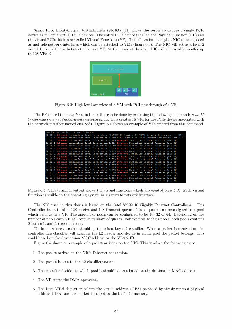
Single Root Input/Output Virtualization (SR-IOV)[11] allows the server to expose a single PCIedevice as multiple virtual PCIe devices. The entire PCIe device is called the Physical Function (PF) andthe virtual PCIe devices are called Virtual Functions (VF). This allows for example a NIC to be exposedas multiple network interfaces which can be attached to VMs (figure 6.3). The NIC will act as a layer 2switch to route the packets to the correct VF. At the moment there are NICs which are able to offer upto 128 VFs [9].
Figure 6.3: High level overview of a VM with PCI passthrough of a VF.
The PF is used to create VFs, in Linux this can be done by executing the following command: echo 16>/sys/class/net/ens785f0/device/sriov numvfs. This creates 16 VFs for the PCIe device associated withthe network interface named ens785f0. Figure 6.4 shows an example of VFs created from this command.
Figure 6.4: This terminal output shows the virtual functions which are created on a NIC. Each virtualfunction is visible to the operating system as a separate network interface.
The NIC used in this thesis is based on the Intel 82599 10 Gigabit Ethernet Controller[4]. ThisController has a total of 128 receive and 128 transmit queues. These queues can be assigned to a poolwhich belongs to a VF. The amount of pools can be configured to be 16, 32 or 64. Depending on thenumber of pools each VF will receive its share of queues. For example with 64 pools, each pools contains2 transmit and 2 receive queues.
To decide where a packet should go there is a Layer 2 classifier. When a packet is received on thecontroller this classifier will examine the L2 header and decide in which pool the packet belongs. Thiscould based on the destination MAC address or the VLAN ID.
Figure 6.5 shows an example of a packet arriving on the NIC. This involves the following steps:
1. The packet arrives on the NICs Ethernet connection.
2. The packet is sent to the L2 classifier/sorter.
3. The classifier decides to which pool it should be sent based on the destination MAC address.
4. The VF starts the DMA operation.
5. The Intel VT-d chipset translates the virtual address (GPA) provided by the driver to a physicaladdress (HPA) and the packet is copied to the buffer in memory.
37
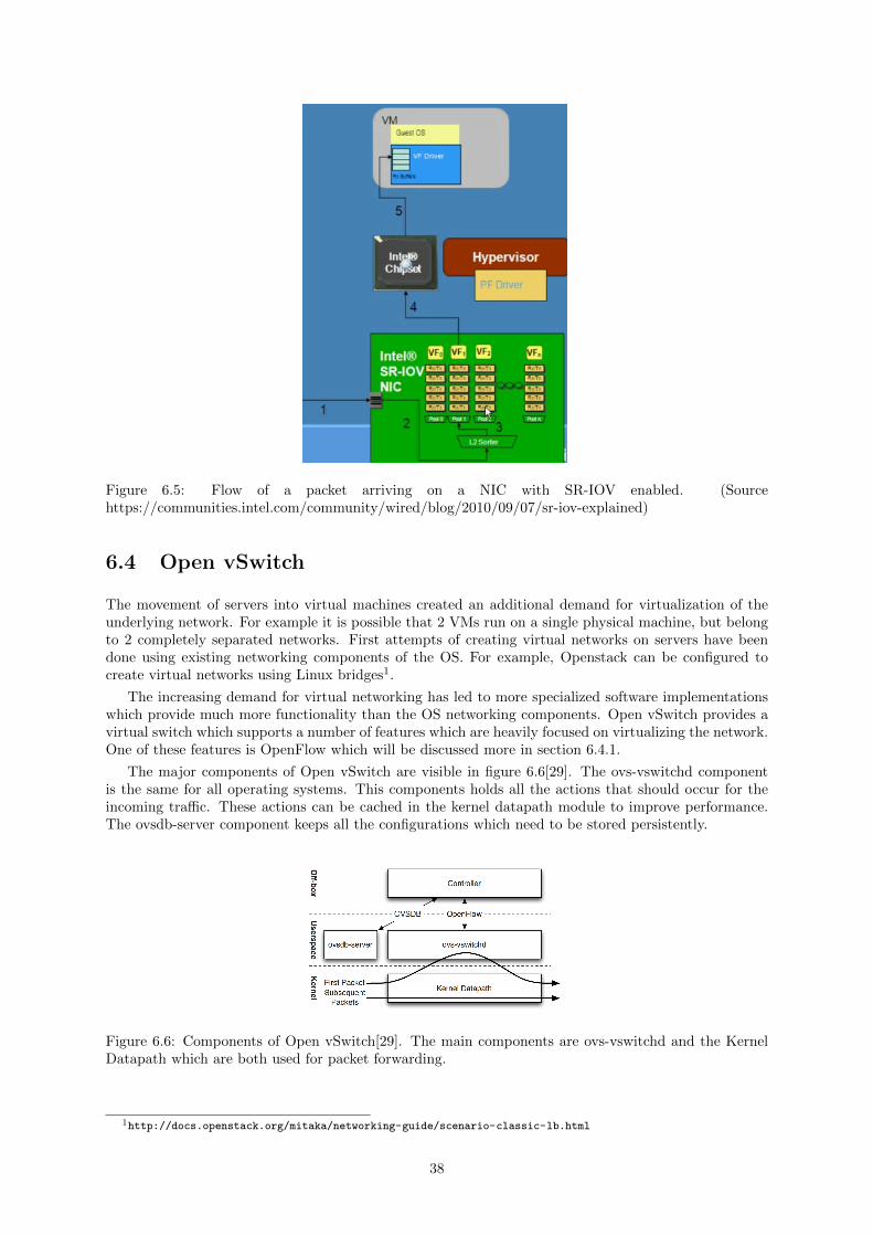
Figure 6.5: Flow of a packet arriving on a NIC with SR-IOV enabled. (Sourcehttps://communities.intel.com/community/wired/blog/2010/09/07/sr-iov-explained)
6.4 Open vSwitch
The movement of servers into virtual machines created an additional demand for virtualization of theunderlying network. For example it is possible that 2 VMs run on a single physical machine, but belongto 2 completely separated networks. First attempts of creating virtual networks on servers have beendone using existing networking components of the OS. For example, Openstack can be configured tocreate virtual networks using Linux bridges1.
The increasing demand for virtual networking has led to more specialized software implementationswhich provide much more functionality than the OS networking components. Open vSwitch provides avirtual switch which supports a number of features which are heavily focused on virtualizing the network.One of these features is OpenFlow which will be discussed more in section 6.4.1.
The major components of Open vSwitch are visible in figure 6.6[29]. The ovs-vswitchd componentis the same for all operating systems. This components holds all the actions that should occur for theincoming traffic. These actions can be cached in the kernel datapath module to improve performance.The ovsdb-server component keeps all the configurations which need to be stored persistently.
Figure 6.6: Components of Open vSwitch[29]. The main components are ovs-vswitchd and the KernelDatapath which are both used for packet forwarding.
1http://docs.openstack.org/mitaka/networking-guide/scenario-classic-lb.html
38

6.4.1 Software Defined Networking
The goal of SDN is to increase programmability of existing networking devices by decoupling the dataplane (or forwarding plane) and the control plane [28]. The data plane defines the part of a networkingdevice that processes each individual packet that arrives at an interface. This part often exists in theform of Application-specific integrated circuits (ASIC) in order achieve high performance on a largenumber of ports. The control plane makes decisions on where the traffic should be sent, this part isconcerned with the network topology and doesn’t require specialized hardware.
Traditional networks use routers and switches which have vendor-specific control interfaces whereeach device makes its own decision about where traffic should be sent. By decoupling the control-and data plane, we can create a centralized controller which can run in software and controls multiplenetworking devices. This requires an open protocol like OpenFlow to allow communication [24] betweenthe controller and the forwarding devices.
At first sight it seems that NFV and SDN are two competing technologies, they both try to solvethe same problem using a different approach. In reality this is not the case, SDN solutions like Open-Flow allow some degree of programmability but they are not very suitable for more complex networkapplications like a router or a statefull firewall. Both technologies have certain shortcomings which canbe resolved by combining them into one complete solution. One example of this is the deployment ofnetwork services. This is done by deploying VNFs as VMs which are interconnected using SDN.
OpenFlow
As mentioned before, OpenFlow defines an open communication protocol to program the data plane inswitches and routers. The protocol needs to be supported by the device in order to work, these devicesare called OpenFlow switches. Figure 6.7 shows an example of an OpenFlow switch.
Figure 6.7: Example of an OpenFlow switch. The flow table is updated by the controller through thesecure channel. The controller can be connected to multiple OpenFlow switches.
OpenFlow is by far the most supported SDN technology and a lot of vendors of networking devicesadded this protocol to their products. The forwarding decisions in an OpenFlow switch are based on oneor multiple flow tables which contain flow entries associated with an action. The flow tables are updatedby the controller through a secure channel using the OpenFlow protocol. Each flow-entry is associatedwith a simple action, the 3 basic ones are:
• Forward the packet to a certain port. It is possible to modify the packet headers like adding aVLAN tag.
• Encapsulate and forward this packet to the controller through the secure channel. The controllercan choose to insert a new flow-entry to handle all packets belonging to this flow, in this case onlythe first packet is sent to the controller.
• Drop packets that match this flow-entry. This can be used for to avoid security threats like denial-of-service attacks.
39
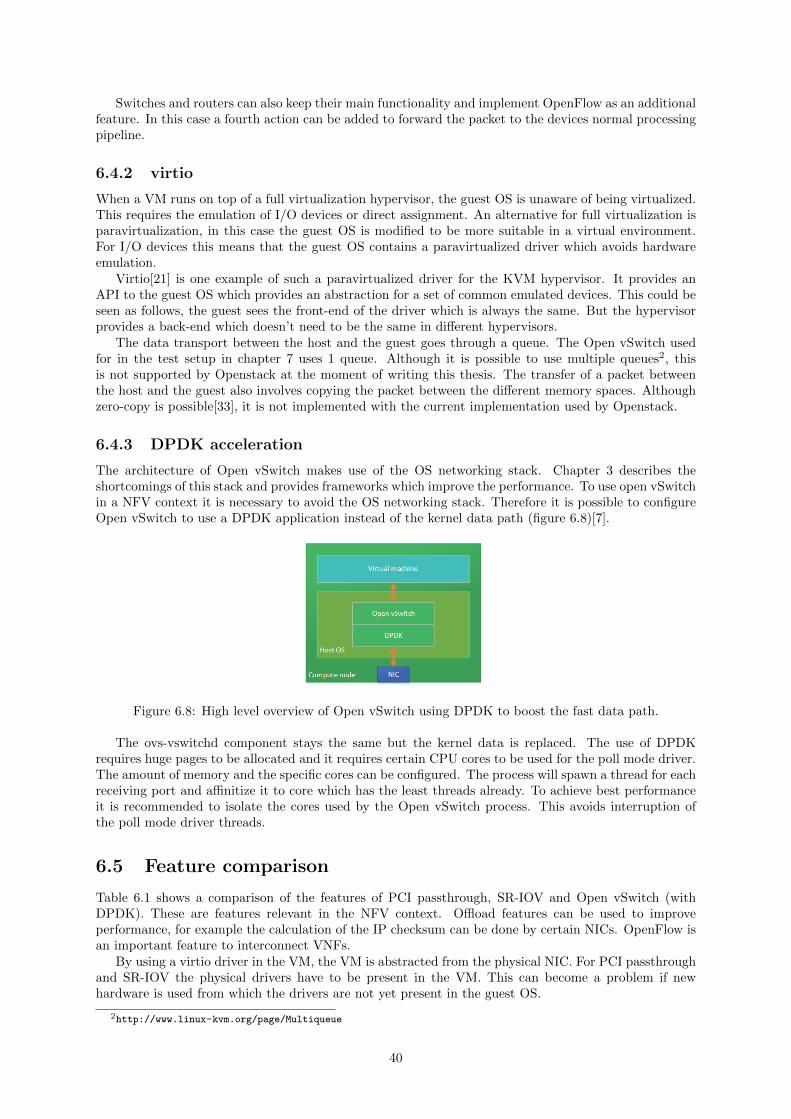
Switches and routers can also keep their main functionality and implement OpenFlow as an additionalfeature. In this case a fourth action can be added to forward the packet to the devices normal processingpipeline.
6.4.2 virtio
When a VM runs on top of a full virtualization hypervisor, the guest OS is unaware of being virtualized.This requires the emulation of I/O devices or direct assignment. An alternative for full virtualization isparavirtualization, in this case the guest OS is modified to be more suitable in a virtual environment.For I/O devices this means that the guest OS contains a paravirtualized driver which avoids hardwareemulation.
Virtio[21] is one example of such a paravirtualized driver for the KVM hypervisor. It provides anAPI to the guest OS which provides an abstraction for a set of common emulated devices. This could beseen as follows, the guest sees the front-end of the driver which is always the same. But the hypervisorprovides a back-end which doesn’t need to be the same in different hypervisors.
The data transport between the host and the guest goes through a queue. The Open vSwitch usedfor in the test setup in chapter 7 uses 1 queue. Although it is possible to use multiple queues2, thisis not supported by Openstack at the moment of writing this thesis. The transfer of a packet betweenthe host and the guest also involves copying the packet between the different memory spaces. Althoughzero-copy is possible[33], it is not implemented with the current implementation used by Openstack.
6.4.3 DPDK acceleration
The architecture of Open vSwitch makes use of the OS networking stack. Chapter 3 describes theshortcomings of this stack and provides frameworks which improve the performance. To use open vSwitchin a NFV context it is necessary to avoid the OS networking stack. Therefore it is possible to configureOpen vSwitch to use a DPDK application instead of the kernel data path (figure 6.8)[7].
Figure 6.8: High level overview of Open vSwitch using DPDK to boost the fast data path.
The ovs-vswitchd component stays the same but the kernel data is replaced. The use of DPDKrequires huge pages to be allocated and it requires certain CPU cores to be used for the poll mode driver.The amount of memory and the specific cores can be configured. The process will spawn a thread for eachreceiving port and affinitize it to core which has the least threads already. To achieve best performanceit is recommended to isolate the cores used by the Open vSwitch process. This avoids interruption ofthe poll mode driver threads.
6.5 Feature comparison
Table 6.1 shows a comparison of the features of PCI passthrough, SR-IOV and Open vSwitch (withDPDK). These are features relevant in the NFV context. Offload features can be used to improveperformance, for example the calculation of the IP checksum can be done by certain NICs. OpenFlow isan important feature to interconnect VNFs.
By using a virtio driver in the VM, the VM is abstracted from the physical NIC. For PCI passthroughand SR-IOV the physical drivers have to be present in the VM. This can become a problem if newhardware is used from which the drivers are not yet present in the guest OS.
2http://www.linux-kvm.org/page/Multiqueue
40

PCI passthrough SR-IOV Open vSwitch
Max. virtual interfaces 1/port 64/port3 UnlimitedOffload features yes yes noOpenFlow support no no yesVirtio driver no no yesLive migration no no yes
Table 6.1: Comparison of the features which are relevant in the NFV context.
6.6 Conclusion
There are 2 approaches available for creating a data path used for data plane packet processing in avirtualized environment. Either by direct hardware assignment or a virtual switch.
Direct hardware assignment, in this case PCI passthrough, can be achieved with the support of anIOMMU like Intel VT-d. In this case the VM has full control over the PCI device. Since the devicecannot be shared there is a possibility to use SR-IOV which allows the creation of virtual functions ona single NIC. Each virtual function can be assigned to a different VM.
Using a virtual switch, like Open vSwitch, enables certain features which are very useful in the contextof NFV. OpenFlow creates more programmability in the network interconnecting VNFs. Virtio allowsmore generality and abstraction between the guest OS and the underlying hardware. If live migration isavailable it is possible to orchestrate VNFs in a way which makes more optimal use of the infrastructure.
Plain Open vSwitch suffers from the performance limitations explained in chapter 3. This has beenthe motivation to create an alternative configuration which uses DPDK to accelerate the data path. Theanswer for the first research question is as follows: since Open vSwitch uses the OS networking stack itis not suitable for data-plane packet processing.
The features which are available using Open vSwitch align much more with the cloud model. TheVM is completely abstracted from the underlying hardware and there are much more orchestration andmanagement capabilities. This answers the second research question since there is a demand for thesefeatures which are not available using PCI passthrough and/or SR-IOV. Therefore a virtual switch canprovide an alternative.
41

42

Chapter 7
NFV data path test setup
7.1 Introduction
All tests are performed using the Open Platform for NFV (OPNFV)1 Brahmaputra. This platform addscapabilities to Openstack which make it more suitable for NFV use cases. The focus of this thesis willbe on the OVSNFV project which upgrades Open vSwitch (OVS) to use DPDK to accelerate the datapath. The choice for using OPNVF is mainly focused on the tests which use Open vSwitch with DPDK.Since Openstack supports PCI passthrough and SR-IOV by default these can be done with a standarddeployment.
Besides the OVSNFV project there are other projects which add features and capabilities to theplatform. These features can be enabled for a certain target scenario, but it is not necessary to use allof them.
OPNFV can be deployed using multiple deployment tools, but they do not all support the samefeatures. The administrator can choose the desired deployment tool based on the supported featuresand certain properties of the platform. For example, some tools us Ubuntu as the host OS and othertools use CentOS. The tool used for these test is called Fuel since this is the only tool that supports theOVSNFV plugin.
7.2 Hardware components
All tests are executed on a dual socket Intel server board with 2 Xeon E5 processors. Table 7.1 showsmore detailed information about the components.
Item Description
Processor 2x Intel Xeon CPU E5-2697 v3 @ 2.60GHzPlatform Intel Server Board S2600WTTNetwork interface 2x dual port Intel 82599ES 10-Gigabit SFI/SFP+Memory 8x 8GB DDR4BIOS SE5C610.86B.01.01.0016.033120161139
Table 7.1: Hardware properties of the Compute node.
7.3 Software components
7.3.1 Host
Table 7.2 shows the software components used by the Openstack compute nodes. This node is used tohost the VMs that run the tests. The software components are mostly the same except for QEMU andLibvirt. The OPNFV plugin that is used to install Open vSwitch with DPDK also installs a predefinedversion of QEMU and Libvirt to avoid dependency issues. Also, the Open vSwitch with DPDK versionis not applicable for PCI passthrough and SR-IOV.
1https://www.opnfv.org/
43

Item Description
Cloud platformMirantis 8.0OpenStack Liberty
Operating system Ubuntu 14.04 kernel 3.13.0-85-generic x86 64
QEMU-KVM
SR-IOV:libvirt 1.2.9qemu 2.4.0Open vSwitch + DPDK:libvirt 1.2.12qemu 2.2.1
Open vSwitch with DPDKOpen vSwitch 2.4.90DPDK 2.0.0
Table 7.2: Software properties of the Compute node.
7.3.2 Guest
The VM is running a CentOS distribution. Since the VM can be any OS the choice has been made touse a familiar system. Table 7.3 shows more detailed information about the VM.
Item Description
Operating system CentOS 7.2 kernel 3.10.0-327.el7.x86 64 x86 64DPDK DPDK 2.2.0PROX PROX 0.31DATS DATS 0.31
Table 7.3: Software properties of the VM.
7.4 Test metrics
To compare networking devices of multiple vendors, it is necessary to execute tests that generate com-parable data. This report is focused on measuring the throughput, this is defined in RFC 1242 by thenumber of packets that can be processed without any loss. The tests are run using packet sizes of 64,128, 256, 512, 1024, 1280 and 1518 bytes. These are include the smallest and largest possible packetsizes together with a range of sizes in between with a finer precision for smaller sizes.
Some tests change the length of the packet, in this case the reported packet size is the size on thepart where the packet is the largest. For example, if the test case adds a 4-byte MPLS tag, then thesmallest packet size will be 68 bytes on the tagged side and the 64 bytes on the untagged side. For thenext packet size it will be 128 on the tagged side and 124 on the untagged side. The reported packetsizes are the sizes on the part where the frame is the largest (68, 128 ... 1518).
Finding the exact point where packets can be processed without loss requires a searching algorithmthat reduces the speed when a test run fails and increases the speed when a test run is successful. Theresults in this report are based on a binary search algorithm. In this case the first test run is done at100% of the speed. If there are no packets lost after running the test for 5 seconds it is considered asuccess. Otherwise the test is failure and repeated at half the rate until the difference between 2 runs isless than 1%.
The device that is being tested is referred to as the System Under Test (SUT). The ideal setup woulduse a tester which both transmits and receives the traffic. The generated traffic consists of UDP packets.In the context of NFV the SUT will not be a physical device but a Virtual Network Function (VNF).The VNF will run as a VM on an Openstack compute node.
By running multiple use cases which represent a certain category of network functions we can deter-mine the characteristics of the configuration. Each of the selected use cases generates a unique workloadwhich is more sensitive to different parts of the system.
As mentioned before, the throughput is measured in packets per second. We will compare themeasured results with the theoretical maximum of a 10Gbit/s link. To calculate this maximum we need
44

Figure 7.1: Logical view of the test setup.
divide the speed of the link with the size of a packet with the inter-frame gap. Equation 7.1 shows thecalculation for 64 byte packets and table 7.4 shows the maximum values for different packet sizes.
10∗1098 bytes/s
(64 + 20)bytes= 14880952pps ≈ 14.88Mpps (7.1)
Packet size (bytes) Maximum throughput (Mpps)
64 14.88128 8.45256 4.53512 2.351024 1.201280 0.961518 0.81
Table 7.4: Maximum theoretical throughput for different packet sizes on a 10Gbit/s link.
To run these tests we need a tester which is able to generate traffic at 10Gbit/s. This can be doneby a dedicated appliance or software running on a commodity server. When traffic is generated atthe maximum speed, also called line rate, the gap between each packet is minimized. When trafficis generated at a lower rate this gap will increase, ideally the gap between each packet would be thesame. Unfortunately this is very hard to achieve using an application which runs on a commodity server.Therefore dedicated appliances are available which can guarantee a much higher degree of precision ofwhen each packet is sent.
The choice between a software- and a hardware based solution should not be taken lightly. Somecompanies have trusted hardware which has been validated to work correctly. Therefore it is easy toreproduce test results using the same hardware. A software based generator is dependent on the platformit runs on. The chosen hardware, the OS and the configuration of the generator can all influence thetest results. In a sense it also measures the testers performance. On the other hand it allows for moreflexibility when setting up the test configuration.
7.5 Test cases
This test setup uses a DPDK software application which both generates and receives the traffic. We willbe using a tool called PROX which can be used as the tester and the SUT. At the tester side it will beused to generate and analyze the traffic. At the side of the SUT, PROX can be used to create DPDKapplications which execute certain network functions.
To compare different configurations we will run 7 different test cases on the SUT. The first 5 testcases are synthetic test cases. The last 2 test cases represent realistic test scenarios that can be part of anetwork. To run all these test cases a tool called Dataplane Automated Testing System (DATS) is usedwhich is available on Github2. This tool runs on a system with 4 times 10Gbit/s NICs which generatesa maximum of 40Gbit/s. The first 3 test cases have the following architecture:
The implementation possibilities of a DPDK application are dependent on the environment where itruns. It can be possible that an implementation which works in a certain environment doesn’t work inanother environment. This is also the case with these test cases. First the buffer size of the memoryregion which can be accessed by the NIC, also called descriptors, can be different for different scenario’s.When using PCI passthrough the size can be around 256 descriptors. The NIC itself is able to buffer
2https://github.com/nvf-crucio/DATS
45

Figure 7.2: Architecture of the first 3 test cases. This picture visualizes the architecture of the DPDKapplication running in the guest OS. Each task runs on a different core.
packets which avoids losing packets. In the case of SR-IOV the NIC doesn’t buffer packets. It it istherefore necessary to allocate a larger memory region. Therefore these test cases are configured using2048 descriptors.
In some scenario’s it is possible to send packets from multiple tasks to a single TX port. This is thecase for PCI passthrough, but for SR-IOV and Open vSwitch only 1 task can send to a port. The testcases are therefore configured to aggregate packets before sending them to a TX port.
The test results which are generated in this thesis are executed with the same configuration. Intheory it is possible to create optimized configurations for certain environments but this would createless comparable test results.
7.5.1 Layer-2 forwarding
The first test case handles packets from a layer 2 perspective. The application doesnt do any processingexcept for setting a preconfigured source and destination MAC address. The CPU and memory usage isminimal, therefore the performance will mostly be affected by the receive and transmit channel.
7.5.2 Tag/Untag
This test case changes the size of each packet that is received by the SUT. 2 of the 4 task add a 4-byteMPLS tag to each packet and the other 2 strip a 4-byte MPLS tag. This tag is inserted after the Ethernetheader, it is therefore necessary to move this header.
7.5.3 ACL
The third test case will match the traffic against an Access Control List (ACL). The SUT matches 7header fields against a preloaded list of 32K rules. The generated traffic randomizes these fields to makesure that all the rules are hit. For each packet the algorithm looks for the “best” matching rule. If apacket matches multiple rules it will take the rule with the highest priority.
7.5.4 Load distributor
This use-case focuses on identifying flows and making a forwarding decision. A 5-tuple is used to decidewhere the load should be distributed. This tuple consists of the fields that identify a flow so that everypacket that belongs to the same flow is sent to the same port. The load is uniformly distributed over allthe output ports using a hash table of 8M entries. Figure 7.3 shows the architecture of this test case.
Each load distributor stores its own hash table, so there are 4 hash tables with 8M entries. Each hasentry is 16 bytes long, therefore the total amount of memory used for all the hash entries is 512MB.
46

Figure 7.3: Architecture of the load distributor test cases. The test case only uses 4 ports, the figureshows 8 ports for better readability.
7.5.5 Buffering
The buffering test cases measures the impact of the condition when packets get buffered, thus they stayin memory for the extended period of time. This can be part of network to enhance the quality ofstreams. For example, when a CDN is used for multimedia streams there are often multiple layers ofservers which are used to distribute all the stream data. The servers on the edge of the network typicallybuffer stream data to compensate for packet loss. In contrast to the other test cases it only receivespackets on a single port (Figure 7.4).
Figure 7.4: Architecture of the buffering test case.
The packets are buffered for 125ms before they are forwarded. This requires enough memory to holdall the packets before forwarding them. The amount of memory required for each packet is independentof the size of the packets. Since it would the cost of allocating and deallocating memory is very high allpackets are stored in a data structure with the same size. The amount of memory necessary to bufferpackets sent at line rate is approximately 3.3GB.
7.5.6 BNG
The last test cases represent a more realistic scenario called a Border Network Gateway (BNG) which isthe access point for subscribers to the internet (Figure 7.5).
Figure 7.5: Basic BNG architecture. The image visualizes the role of the BNG application in a networkservice provided by an ISP.
47

In a real scenario multiple users would be connected to a digital subscriber line access multiplexer(DSLAM) which would send the traffic on a single Ethernet connection to the BNG router. At this pointthe different subscribers are identified using two VLAN tags. The BNG router translates the traffic toan appropriate format which can be routed on the Internet side. Our test scenario has 64K subscribers.
The traffic that arrives at a NIC first goes to a load balancer. Then the load balancers distribute thetraffic uniformly to a number of worker tasks. These worker tasks map the internet traffic to CPE trafficand the other way around. Each worker thread has a lockless queue configured where it receives traffic.When a load balancer has decided to which worker the packet should go it will transfer the packet tothis queue (Figure 7.6).
Figure 7.6: Architecture of the BNG test case.
7.5.7 BNG+QOS
The last test case adds Quality of Service (QOS) functionality to the BNG router[25]. Without QOSthere is no guarantee about the traffic rate for each user. QOS policies determine how the traffic flowfor each user influences each other. This is achieved by managing when packets should be transmittedor dropped using queues (Figure 7.7)
Figure 7.7: Architecture of the BNG+QOS test case.
7.6 Physical setup
As mentioned before all test setups have been configured using the platform but with a different config-uration. The SUT has been deployed using Fuel as the deployment tool which is delivered by OPNFVBrahmaputra. An Openstack environment requires at least 1 controller node and 1 compute node. Thediagrams only show the compute nodes since they are the ones that do the data processing.
48

To optimize the compute node for packet processing it is necessary to do some manual configurationafter the installation is done. This is not how it is supposed to be used in an environment with a lot ofnodes. This could be overcome by creating a Fuel plugin which does the necessary configuration.
The tester is not part of the Openstack environment, but it is directly connected to the computenode using 4x 10Gbit/s connections. Both the tester and SUT have a communication channel with aDATS controller which sends commands to both system which run the tests.
7.6.1 PCI passthrough setup
The PCI passthrough setup (Figure 7.8) attaches the NIC ports directly to the VM which bypasses thehost OS. The Open vSwitch data path is still used to create a management interface. This managementinterface is used by DATS to launch the correct PROX application. The tester runs a PROX applicationwhich is used to generate traffic, this application is also managed by DATS.
Figure 7.8: PCI passthrough test setup. Each port of the NICs in the compute node is directly assignedto the VM. The Tester runs a traffic generator/analyzer in bare-metal.
7.6.2 SR-IOV setup
The SR-IOV setup is similar to the PCI passthrough setup (Figure 7.9). Instead of assigning a completeport to the VM the port is first divided in Virtual Functions (VF). Instead of assigning the entire NICport (PF), a VF of each port is attached to the VM using PCI passthrough.
49

Figure 7.9: SR-IOV test setup with PCI passthrough of the VFs.
Although SR-IOV can be used without PCI passthrough there is no real benefit if doing this. There-fore the convention in this thesis is that whenever SR-IOV is mentioned it means that PCI passthoughof the VF is used.
7.6.3 Open vSwitch with DPDK setup
Using the OVSNFV plugin we can accelerate Open vSwitch using DPDK. The plugin is still in an exper-imental phase and is not ready to use in production environments, but it can be used for experimentalpurposes. Using this setup the data plane traffic and the management traffic are both sent on the samevirtual switch (Figure 7.10). Openstack uses Open vSwitch bridges to decide to which port the trafficshould be forwarded. The VM is configured to have 5 virtual interfaces, each interface is mapped to asingle port. The first port is used to manage PROX and the other 4 ports are used to send data.
Figure 7.10: Open vSwitch with DPDK setup. The NIC ports are connected to the virtual switch whichexposes virtio interfaces to the VM.
50

When using this setup it is necessary to assign certain cores to Open vSwitch. 1 core is necessary forthe ovs-vswitchd process and there has to be at least 1 core for packet processing. In this setup OpenvSwitch has been configured to use 5 hyper threaded cores for packet processing.
Figure 7.11: Distribution of cores among Open vSwitch and the VM.
Figure 7.11 shows the CPU numbering of a dual socket server board. ID 0-13 belong to the cores onsocket 0 and ID 28-41 are their hypertreaded siblings. For example core 1 and 29 are siblings. Socket1 uses ID 14-27 and 42-55, but this socket is not used for packet processing. Core 0 is used for theovs-vswitchd process. Core 1-5 with their hypertreads are used for the pmd threads of Open vSwitch.The remaining 8 hyperthreaded cores are used by the VM.
7.7 Conclusion
This chapter describes the components used for testing different data paths between the NIC and theVM. The different test setups are installed using the same platform called OPNFV. By configuring eachtest setup in a different way it is possible to create a different data path.
To compare the different test setups we are using 7 different test cases with distinctive characteristics.In this way it is possible to make a more accurate conclusion of the system without digging into theimplementation details of the components. Chapter 8 shows performance results using these test cases.
51

52

Chapter 8
NFV data path test results
8.1 Introduction
In this chapter the performance results of the different technologies are presented and compared. Firstwe present the test results for throughput measurements. These measurements are created for 7 differenttest cases which are described in section 7.5.
Secondly the throughput results are compared in 2 ways. PCI passthrough and SR-IOV are comparedto see if there is a difference between assigning a PF to the VM and a VF to the VM. Also SR-IOV iscompared to Open vSwitch with DPDK, this comparison is the main subject for this thesis. SR-IOVhas already been proven to achieve decent performance but Open vSwitch with DPDK is still in anexperimental phase when this thesis is written. The goal is to investigate if Open vSwitch with DPDKis a valid alternative and in which use cases.
Finally the latency between sending and receiving packets on the tester is compared between all 3test setups. This comparison has only been done on the L2 forwarding test case.
8.2 Throughput results
The test cases are executed using the smallest possible packet size and packet sizes of 128, 256, 512, 1024,1280 and 1518 bytes. The smallest possible packet size depends on the test case, table 8.1 shows thesmallest packet size for each test case. The results are grouped by test case where each color representsa different packet size.
Test case Smallest packet size (bytes)
L2 forwarding 64Tag/Untag 68ACL 64Load distributor 64Buffering 64BNG 78BNG+QOS 78
Table 8.1: Smallest packet size for each test case.
The results are originally produced in packets per second. This is calculated by counting the amountof packets received in a certain amount of time and dividing this amount by the time passed. The resultsare presented in percentage of line rate for better readability. This means that 100% is equal to 40Gbit/s for all test cases except for the buffering test case. For the buffing test case 100% corresponds to10Gbit/s.
8.2.1 PCI passthrough throughput
Figure 8.1 shows the result for the PCI passthough setup. The L2 forwarding test case shows a throughputof 100% for packet sizes greater or equal to 128 bytes. The maximum throughput for 64 bytes packets
53

is around 80%. This is a result of the PCI Express 2.0 transfer rate which acts as a bottleneck[25].
Figure 8.1: PCI passthrough throughput results. The throughput is displayed as percentage of line-rate.Each color represents a different packet size.
The Tag/Untag and ACL test cases have a lower throughput for the smallest packet size but theyalmost reach the maximum for the 128 bytes packets. These test cases are a bit more complex than thefirst one and require more processing power.
The Load distributor and buffering test cases show a lower throughput for both the smallest packetsize and the 128 bytes packets. Both test cases use more memory than there is available in the cachewhich results in cache invalidation.
Even though the BNG test case is much more complex than other test cases, by using load balancersand enough worker threads it still shows a decent performance. With QOS it shows a low performancefor the smallest packet sizes. Each receiving port has a single QOS task which acts as a bottleneck.Nevertheless the throughput reaches more than 90% for 256 bytes packets and 100% for packets from512 bytes and larger.
The PCI passthrough setup shows a similar behavior for the different test cases. The smallest packetsizes show a decreased throughput but from 256 bytes and larger they almost all reach line rate.
8.2.2 SR-IOV throughput
Figure 8.2 shows the results for the SR-IOV setup. The results look very similar to the results of thePCI passthrough setup. Section 8.3.1 shows a detailed comparison with the PCI passthrough setup.
54

Figure 8.2: SR-IOV throughput results. The throughput is displayed as percentage of line-rate. Eachcolor represents a different packet size.
8.2.3 Open vSwitch + DPDK throughput
The throughput results of the Open vSwitch with DPDK are shown in figure 8.3. The throughput forthe smallest packet sizes are much lower than the other test setups. For the smallest packet size thethroughput never reaches 25% or higher.
Figure 8.3: Open vSwitch with DPDK throughput results. The throughput is displayed as percentageof line-rate. Each color represents a different packet size.
The first 3 test cases show a similar behavior. The smallest packet size is around 20%, the 128 bytespackets are around 35%, the 256 bytes packets are around 65% and packets from 512 bytes almost reachline rate. It is remarkable to see that the ACL test case shows a better performance than the first 2 testcases. We will discuss this further in section 8.2.3.
The last 4 test cases show a lower performance for almost all packet sizes. All of these test cases usea lot of memory when they process packets. Open vSwitch also uses memory when processing packets,this means that the Last Level Cache (LLC) is shared between the VM and Open vSwitch. When theVM uses a small amount of memory there is little interference between the VM and Open vSwitch. Butwhen the VM uses a lot of memory, the VM causes cache invalidation for Open vSwitch, therefore they
55

act as noisy neighbors.
ACL performance
The ACL test case shows a better performance than the L2 forwarding test case. This behavior isunexpected since the ACL is computational more expensive. A possible explanation could be that bothtest cases handle packets in different bulk sizes.
A DPDK application processes packets in bulks instead of one by one. The size of this bulk isdependent on the performance of the application and the configuration. When an application is processingpackets very fast it will have small bulks, if it is slow it will use large bulks.
Figure 8.4: Bulk size distribution of the L2 forwarding and ACL test cases. The Y-axis has a logarithmicscale which allows to see the details more clearly.
Figure 8.4 shows distribution of bulk sizes in a certain amount of time. The yellow bars show thebulk sizes of the ACL test case, the blue bars show the L2 forwarding bulk sizes. The L2 forwarding testcase has a lot of small bulks, the amount of bulks show a decrease when the bulk size becomes higher.There is a small increase in amount of bulks at bulk sizes of 32 packets, but there are no bulks with morepackets.
The ACL test handles a lot more packets in bulks with sizes up to 12 packets. It is important tonotice that a logarithmic scale has been used, for example the number of bulks with size 12 is more than300 times higher for the ACL test case than it is for the L2 forwarding test case. This indicates that thepackets are more evenly distributed among larger bulk sizes which allow a higher throughput.
The cause of this difference has not been identified, it could be a result of configuration. It is importantto notice that not only the complexity matters but also implementation details. A comparison betweendifferent test cases is therefore not justified. This is also the reason why the choice has been made to usethe exact same implementation for each test case on all the test setups.
8.3 Throughput comparison
In this section the throughput is compared between different setups. The data is presented in a way thatshows what the increase or decrease is when using one setup instead of another. For example, if setupA has a throughput of 100% and setup B has a throughput of 80%, then system B is 20% slower thansystem A. The following formula is used for this calculation:
difference in percentage =throughput of setup B
throughput of setup A− 1 (8.1)
The first comparison is between PCI passthrough and SR-IOV. The motivation behind this compar-ison is to see if there is a performance penalty between using the PF and the VF of a NIC. Thereforethe comparison is focused on the virtualization capabilities of the NIC.
56
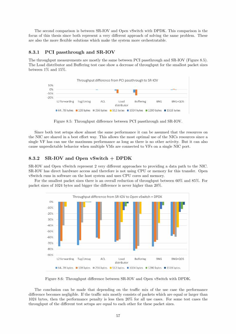
The second comparison is between SR-IOV and Open vSwitch with DPDK. This comparison is thefocus of this thesis since both represent a very different approach of solving the same problem. Theseare also the more flexible solutions which make the system more orchestratable.
8.3.1 PCI passthrough and SR-IOV
The throughput measurements are mostly the same between PCI passthrough and SR-IOV (Figure 8.5).The Load distributor and Buffering test case show a decrease of throughput for the smallest packet sizesbetween 1% and 15%.
Figure 8.5: Throughput difference between PCI passthrough and SR-IOV.
Since both test setups show almost the same performance it can be assumed that the resources onthe NIC are shared in a best effort way. This allows the most optimal use of the NICs resources since asingle VF has can use the maximum performance as long as there is no other activity. But it can alsocause unpredictable behavior when multiple VMs are connected to VFs on a single NIC port.
8.3.2 SR-IOV and Open vSwitch + DPDK
SR-IOV and Open vSwitch represent 2 very different approaches to providing a data path to the NIC.SR-IOV has direct hardware access and therefore is not using CPU or memory for this transfer. OpenvSwitch runs in software on the host system and uses CPU cores and memory.
For the smallest packet sizes there is an overall reduction of throughput between 60% and 85%. Forpacket sizes of 1024 bytes and bigger the difference is never higher than 20%.
Figure 8.6: Throughput difference between SR-IOV and Open vSwitch with DPDK.
The conclusion can be made that depending on the traffic mix of the use case the performancedifference becomes negligible. If the traffic mix mostly consists of packets which are equal or larger than1024 bytes, then the performance penalty is less then 20% for all use cases. For some test cases thethroughput of the different test setups are equal to each other for these packet sizes.
57
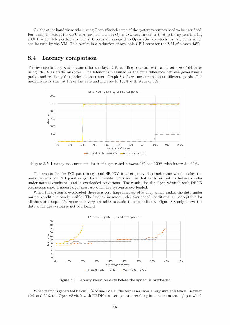
On the other hand there when using Open vSwitch some of the system resources need to be sacrificed.For example, part of the CPU cores are allocated to Open vSwitch. In this test setup the system is usinga CPU with 14 hyperthreaded cores. 6 cores are assigned to Open vSwitch which leaves 8 cores whichcan be used by the VM. This results in a reduction of available CPU cores for the VM of almost 43%.
8.4 Latency comparison
The average latency was measured for the layer 2 forwarding test case with a packet size of 64 bytesusing PROX as traffic analyzer. The latency is measured as the time difference between generating apacket and receiving this packet at the tester. Graph 8.7 shows measurements at different speeds. Themeasurements start at 1% of line rate and increase to 100% with steps of 1%.
Figure 8.7: Latency measurements for traffic generated between 1% and 100% with intervals of 1%.
The results for the PCI passthrough and SR-IOV test setups overlap each other which makes themeasurements for PCI passthrough barely visible. This implies that both test setups behave similarunder normal conditions and in overloaded conditions. The results for the Open vSwitch with DPDKtest setups show a much larger increase when the system is overloaded.
When the system is overloaded there is a very large increase of latency which makes the data undernormal conditions barely visible. The latency increase under overloaded conditions is unacceptable forall the test setups. Therefore it is very desirable to avoid these conditions. Figure 8.8 only shows thedata when the system is not overloaded.
Figure 8.8: Latency measurements before the system is overloaded.
When traffic is generated below 10% of line rate all the test cases show a very similar latency. Between10% and 20% the Open vSwitch with DPDK test setup starts reaching its maximum throughput which
58

causes the latency to increase. The PCI passthrough and SR-IOV test setups show a very similar behaviorfor all the throughput values.
To use the system at its full potential it is desirable to run it at the maximum throughput. Table8.2 shows the minimum, average and maximum latency at this point. It shows some remarkable results.The SR-IOV test setup has a lower average and maximum than the PCI passthrough test setup. AlsoOpen vSwitch with DPDK has a lower maximum than the other test setups.
min (µs) avg (µs) max (µs)PCI passthrough 8 16 94SR-IOV 8 13 85Open vSwitch + DPDK 14 18 43
Table 8.2: Latency at the point each system reaches the maximum throughput.
8.5 Conclusion
In this chapter the performance of 3 different approaches for creating a NFV data path between theNIC and the VM have been compared. The first 2 approaches use a similar technique called PCIpassthrough, first without SR-IOV and then with the use of SR-IOV. These techniques are already usedby telecommunication operators.
The third approach uses a software based data path where the NIC and VM are connected to avirtual switch. This technique is still experimental but it supports certain features which make it anattractive alternative.
With PCI passthrough there is no big difference between when SR-IOV is used or not. The throughputshows only a small (less than 15%) difference under a few conditions. Most of the test cases show theexact same throughput for all the packet sizes. Also there is no big difference between the latencymeasurements. When SR-IOV is used, there even is a small improvement.
When a virtual switch is used there is big difference compared with SR-IOV. The comparison is doneusing Open vSwitch with DPDK as the virtual switch. For the smallest packets sizes there is a reductionof throughput between 60 and 85%. When using larger packet sizes there is a much smaller reduction ofthroughput. For packet sizes of 1024 bytes and larger the reduction is less than 20%. Therefore OpenvSwitch with DPDK is mostly useful for use cases with a traffic mix where most of the packets are 1024bytes or larger. On the other hand, the use of a virtual switch requires CPU cores and memory. In thiscase almost 43% of the CPU cores are assigned to Open vSwitch.
There is no big difference between the latency measurements of SR-IOV and Open vSwitch withDPDK. Therefore the main consideration for choosing the most appropriate technology is the maximumthroughput.
The answer to the third research question is as follows: Open vSwitch with DPDK can be used insteadof SR-IOV. But it has limitations which include a reduced performance especially for packets smallerthan 1024 bytes. It also requires resources on the host which reduces the potential complexity of theVNFs and the amount of VNFs on a single host.
59

60

Chapter 9
Conclusion and discussion
9.1 Open vSwitch performance evaluation
Plain Open vSwitch uses the native networking stack of the OS. This results in a throughput below 1million packets per second for all packet sizes[14]. For packets with a size of 64 bytes this would meanthat the throughput is less than 2%, for the packets with a size of 1518 bytes that would be no more than30%. This means that the system is never reaching line rate even for the largest packet sizes. Using OpenvSwitch with DPDK as the fast data path allows an increase of throughput of more than 15 times[14].
The performance evaluation is based on the results in chapter 8 which are about the throughput andlatency of a VNF running in a VM on a compute node. This includes the data path from the NIC to theVM, the VM itself and the data path back to the NIC. The results from using PCI passthrough withoutSR-IOV and with SR-IOV are in most cases the same. Only a few workloads show a difference which isstill less than 15%. Therefore based on these measurements there is no real performance penalty whenusing SR-IOV .
Open vSwitch with DPDK on the other hand shows a big difference in throughput compared toSR-IOV. The smallest packet sizes show a decrease of more than 60% in most cases, but packet sizes of1024 bytes and larger never show a difference bigger than 20%. Therefore Open vSwitch with DPDKcan best be considered as an alternative in use cases where the traffic mix mostly consists of packets of1024 bytes and larger.
There is a small difference between the latency when Open vSwitch with DPDK is used and SR-IOVunder normal conditions but both are in the same magnitude. Under overload conditions Open vSwitchwith DPDK shows a much larger latency than SR-IOV but this should be avoided at all times.
Another consideration to be made when using Open vSwitch with DPDK is that resources need tobe assigned to the virtual switch which is not the case with SR-IOV. One of these resources is a numberof CPU cores on the host. In the test setup used for this thesis that was 6 cores, leaving 8 cores for theVM. This is a reduction of almost 43% which limits the amount of VNFs and the complexity of eachVNF. Although the throughput decrease is more acceptable for packets of 1024 bytes and larger, thisshould also be considered when choosing the most suitable technology.
Since resources need to be allocated to the virtual switch the question can be posed, can functionalityfrom the virtual switch be offloaded to the NIC. This can partly be done with an Intel Ethernet X710Controller[9] which allows network virtualization offloads like VXLAN. Our prediction is that NFVuse cases will require more offloads features, like OpenFlow, which provide improved performance andaccelerate the adoption of virtual switches and VNFs. These offload features would be very useful in datacenters which are specifically designed for service providers, which can also be called NFV data centers.These kind of data centers are exclusively used for deploying VNFs which create network services.
9.2 Research questions
The research question is divided into 3 specific questions and 1 general question. The 3 specific questionsrelate to the current issues with the data path between the NIC and the VM. The answer to thesequestions are the following:
1. Why is it necessary to optimize the data path between the NIC and the VM?The default data path used by Openstack uses the network stack of the OS. This network stack is
61
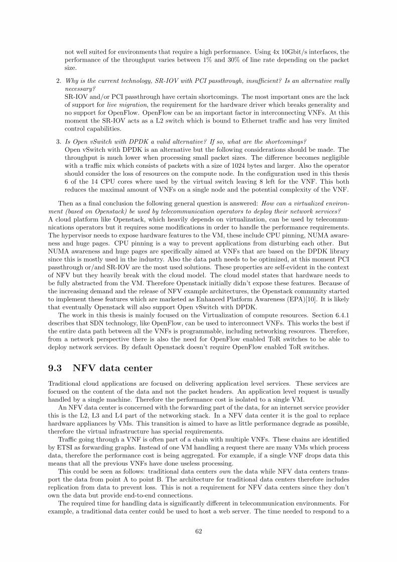
not well suited for environments that require a high performance. Using 4x 10Gbit/s interfaces, theperformance of the throughput varies between 1% and 30% of line rate depending on the packetsize.
2. Why is the current technology, SR-IOV with PCI passthrough, insufficient? Is an alternative reallynecessary?SR-IOV and/or PCI passthrough have certain shortcomings. The most important ones are the lackof support for live migration, the requirement for the hardware driver which breaks generality andno support for OpenFlow. OpenFlow can be an important factor in interconnecting VNFs. At thismoment the SR-IOV acts as a L2 switch which is bound to Ethernet traffic and has very limitedcontrol capabilities.
3. Is Open vSwitch with DPDK a valid alternative? If so, what are the shortcomings?Open vSwitch with DPDK is an alternative but the following considerations should be made. Thethroughput is much lower when processing small packet sizes. The difference becomes negligiblewith a traffic mix which consists of packets with a size of 1024 bytes and larger. Also the operatorshould consider the loss of resources on the compute node. In the configuration used in this thesis6 of the 14 CPU cores where used by the virtual switch leaving 8 left for the VNF. This bothreduces the maximal amount of VNFs on a single node and the potential complexity of the VNF.
Then as a final conclusion the following general question is answered: How can a virtualized environ-ment (based on Openstack) be used by telecommunication operators to deploy their network services?A cloud platform like Openstack, which heavily depends on virtualization, can be used by telecommu-nications operators but it requires some modifications in order to handle the performance requirements.The hypervisor needs to expose hardware features to the VM, these include CPU pinning, NUMA aware-ness and huge pages. CPU pinning is a way to prevent applications from disturbing each other. ButNUMA awareness and huge pages are specifically aimed at VNFs that are based on the DPDK librarysince this is mostly used in the industry. Also the data path needs to be optimized, at this moment PCIpassthrough or/and SR-IOV are the most used solutions. These properties are self-evident in the contextof NFV but they heavily break with the cloud model. The cloud model states that hardware needs tobe fully abstracted from the VM. Therefore Openstack initially didn’t expose these features. Because ofthe increasing demand and the release of NFV example architectures, the Openstack community startedto implement these features which are marketed as Enhanced Platform Awareness (EPA)[10]. It is likelythat eventually Openstack will also support Open vSwitch with DPDK.
The work in this thesis is mainly focused on the Virtualization of compute resources. Section 6.4.1describes that SDN technology, like OpenFlow, can be used to interconnect VNFs. This works the best ifthe entire data path between all the VNFs is programmable, including networking resources. Therefore,from a network perspective there is also the need for OpenFlow enabled ToR switches to be able todeploy network services. By default Openstack doesn’t require OpenFlow enabled ToR switches.
9.3 NFV data center
Traditional cloud applications are focused on delivering application level services. These services arefocused on the content of the data and not the packet headers. An application level request is usuallyhandled by a single machine. Therefore the performance cost is isolated to a single VM.
An NFV data center is concerned with the forwarding part of the data, for an internet service providerthis is the L2, L3 and L4 part of the networking stack. In a NFV data center it is the goal to replacehardware appliances by VMs. This transition is aimed to have as little performance degrade as possible,therefore the virtual infrastructure has special requirements.
Traffic going through a VNF is often part of a chain with multiple VNFs. These chains are identifiedby ETSI as forwarding graphs. Instead of one VM handling a request there are many VMs which processdata, therefore the performance cost is being aggregated. For example, if a single VNF drops data thismeans that all the previous VNFs have done useless processing.
This could be seen as follows: traditional data centers own the data while NFV data centers trans-port the data from point A to point B. The architecture for traditional data centers therefore includesreplication from data to prevent loss. This is not a requirement for NFV data centers since they don’town the data but provide end-to-end connections.
The required time for handling data is significantly different in telecommunication environments. Forexample, a traditional data center could be used to host a web server. The time needed to respond to a
62

web request varies a lot but is measured in the order of milliseconds or seconds. In general, a respond timeof 0.1 second is considered an instantaneous reaction[27]. The expected delay of an networking applianceis much lower. A hardware assisted switch is expected to have a latency of around 25 microseconds[3].
9.4 NFV evolution
NFV is emerging as an alternative for dedicated hardware appliances. A number of use cases have alreadybeen identified as applicable for using NFV technology. Virtual customer edge and mobile packet coreare technologies which are already moving into cloud environments1. One example is a PoC for virtualCPE technology by Telefonica[39]. Figure 7.5 shows the role of such a CPE in an ISP network. Otherexamples include virtual IMS2, virtual EPC3, virtual Gi-LAN[13].
Each use case is addressed individually since the throughput, latency and orchestration requirementscan be different. By studying new use cases telecommunication operators can identify potential for SDNand NFV to design architectures. There needs to be a tight collaboration between telecommunicationoperators and hardware vendors to explore how COTS hardware can be used in these environment. Andmaybe even add features to the hardware to create better support.
1https://www.sdxcentral.com/sdn-nfv-use-cases/2https://www.ericsson.com/ourportfolio/products/ims?nav=productcategory0023https://networks.nokia.com/solutions/packet-core
63

64

Appendix A
Nederlandstalige samenvatting
A.1 NFV achtergrond
Door de evolutie van technologie moeten telecomoperatoren constant hun infrastructuur veranderen omnetwerkdiensten te voorzien. Zo is bijvoorbeeld de vraag naar mobiel internet drastisch gestegen sindssmartphones populair zijn geworden. Hiervoor is nieuwe apparatuur nodig die de nodige functionaliteitondersteunt. Met andere woorden, om nieuwe netwerkdiensten uit te rollen is nieuwe hardware nodig.
Deze evolutie verloopt steeds sneller waardoor telecomoperatoren op zoek zijn gegaan naar alter-natieven op het steeds aankopen en installeren van nieuwe hardware. Sinds enkele jaren is er veelaandacht gegaan naar cloud technologie in data centers. Hierbij wordt gebruik gemaakt van virtualisatietechnologieen om hardware los te koppelen van software. De voordelen van een gevirtualiseerde omgevingvoor telecomoperatoren zijn de volgende:
Sneler uitrollen van netwerkdiensten Bij traditionele netwerkdiensten is de functionaliteit deel vande hardware. In cloud omgevingen wordt de functionaliteit in software voorzien. Hierdoor is hetgemakkelijker om nieuwe diensten uit te rollen.
Dynamisch schalen Met behulp van virtualisatie kan de capaciteit van een netwerkdienst snel endynamisch aangepast worden.
Flexibele plaatsing van netwerkfuncties De fysieke plaats van traditionele netwerkfuncties is vast.Met behulp van virtualisatie kan een netwerkfunctie op eender welke machine geplaatst worden.
Uitbereiding van de infrastructuur Doordat de netwerkfuncties gemakkelijk verplaatst kunnen wor-den is het ook gemakkelijker om de infrastructuur uit te breiden.
De evolutie van traditionele hardware naar gevirtualiseerde omgevingen is ook onder de aandachtgevallen van het European Telecommunications Standards Institute (ETSI) in 2012. ETSI is een organ-isatie die standaarden voor telecommunicatie technologie voorziet en heeft een aparte sectie over NetworkFunctions Virtualization (NFV).
Figuur A.1 toont het NFV architectural framework[16] zoals het beschreven staat door ETSI. Hetdoel is de elementen identificeren die deel uitmaken van een virtuele infrastructuur voor netwerkdiensten.De virtualisatielaag zorgt er voor dat Virtuele NetwerkFuncties (VNF) op eender welke machine gehostkunnen worden. Dit zorgt ervoor dat er ook nieuwe uitdagen zijn rond management en orchestratie. Deelementen die hier deel van uit maken staan rechts op de figuur.
A.2 Data Plane Development Kit
De meeste besturingssystemen hebben een eigen netwerkstack die bepaalde netwerkfuncties voorziet.Door de opkomst van netwerkkaarten van 10Gbit/s en zelfs 40Gbit/s is deze netwerkstack ontoereikend.Het verwerken van pakketten vereist meerdere kopieen en het interrupt mechanisme is onderhevig aanhet interrupt livelock fenomeen[15].
De Data Plane Development Kit (DPDK) bestaat uit een set van libraries die het onder andere mo-gelijk maken om de netwerk stack van het besturingssysteem te omzeilen. Het kopieren van pakketten
65
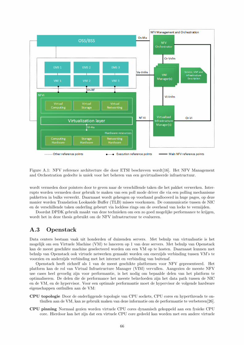
Figure A.1: NFV reference architecture die door ETSI beschreven wordt[16]. Het NFV Managementand Orchestration gedeelte is uniek voor het beheren van een gevirtualiseerde infrastructuur.
wordt vermeden door pointers door te geven naar de verschillende taken die het pakket verwerken. Inter-rupts worden vermeden door gebruik te maken van een poll mode driver die via een polling mechanismepakketten in bulks verwerkt. Daarnaast wordt geheugen op voorhand gealloceerd in huge pages, op dezemanier worden Translation Lookaside Buffer (TLB) misses voorkomen. De communicatie tussen de NICen de verschillende taken onderling gebeurt via lockless rings om de overhead van locks te vermijden.
Doordat DPDK gebruik maakt van deze technieken om een zo goed mogelijke performance te krijgen,wordt het in deze thesis gebruikt om de NFV infrastructuur te evalueren.
A.3 Openstack
Data centers bestaan vaak uit honderden of duizenden servers. Met behulp van virtualisatie is hetmogelijk om een Virtuele Machine (VM) te lanceren op 1 van deze servers. Met behulp van Openstackkan de meest geschikte machine geselecteerd worden om een VM op te hosten. Daarnaast kunnen metbehulp van Openstack ook virtuele netwerken gemaakt worden om enerzijds verbinding tussen VM’s tevoorzien en anderzijds verbinding met het internet en verbinding van buitenaf.
Openstack heeft zichzelf als 1 van de meest geschikte platformen voor NFV gepresenteerd. Hetplatform kan de rol van Virtual Infrastructure Manager (VIM) vervullen. Aangezien de meeste NFVuse cases heel gevoelig zijn voor performantie, is het nodig om bepaalde delen van het platform teoptimaliseren. De delen die de performance het meeste beınvloeden zijn het data path tussen de NICen de VM, en de hypervisor. Voor een optimale performantie moet de hypervisor de volgende hardwareeigenschappen onthullen aan de VM:
CPU topologie Door de onderliggende topologie van CPU sockets, CPU cores en hyperthreads te on-thullen aan de VM, kan ze gebruik maken van deze informatie om de performantie te verbeteren[26].
CPU pinning Normaal gezien worden virtuele CPU cores dynamisch gekoppeld aan een fysieke CPUcore. Hierdoor kan het zijn dat een virtuele CPU core gedeeld kan worden met een andere virtuele
66

CPU core. Door virtuele CPU cores te pinnen aan fysieke CPU cores, wordt voorkomen dat zegedeeld worden.
huge pages Wanneer in de VM een DPDK applicatie wordt gebruikt, is het aangewezen om gebruikte maken van huge pages. Deze moeten eerst gealloceerd worden op de compute node en kunnenvervolgens onthuld worden aan de VM.
NUMA awareness Sommige moederborden hebben meerdere CPU sockets. Voor deze moederbordenkan de performantie verschillen van PCI devices en RAM geheugen voor de verschillende CPU’s.Ieder PCI device, geheugenkanaal en CPU socket behoort tot een Non-uniform memory access(NUMA) node. DPDK applicaties kunnen deze informatie gebruiken en zoveel mogelijk proberenom PCI devices en geheugenkanalen te gebruiken die bij de NUMA node van een CPU behoren.
A.4 NFV data path
Wanneer een VM wordt gelanceerd op een compute node, dan zijn er 2 methodes om een data pathte creeren met de NIC: Met behulp van een virtuele switch of door middel van directe toekenningvan hardware. De virtuele switch is een software applicatie die aan NIC staat gekoppeld en aan de VM.Hierdoor is het mogelijk om data tussen de VM en de NIC te versturen. Directe toekenning van hardwarecreeert een direct data path tussen de VM en de NIC met behulp van PCI passthrough of/en SR-IOV.
A.4.1 PCI passthrough
Om de beperkingen van een virtuele switch te vermijden is het mogelijk om de NIC rechtstreeks aan deVM te koppelen (Figuur A.2), dit wordt PCI passthrough genoemd. Hierdoor heeft de VM de volledigecontrole over de NIC en worden de performantieproblemen met een virtuele switch vermeden. Anderzijdsis het niet mogelijk om een NIC te delen met meerdere VM’s. Met andere woorden, als er meerdere VM’szijn die ieder een direct data path naar een NIC willen hebben, dan moet voor iedere VM een aparteNIC aanwezig zijn.
Figure A.2: Visuele weergave van een VM met PCI passthrough. De VM kan het PCI device gebruikenzonder dat de host moet ingrijpen.
A.4.2 SR-IOV
Single Root I/O Virtualization (SR-IOV) is een hardware eigenschap op het PCI device dat ervoor zorgtdat 1 PCI device als meerdere virtuele PCI devices verschijnt. Deze virtuele PCI devices worden VirtualFunctions (VF) genoemd. Het normale PCI device wordt de Physical Function (PF) genoemd. EenPCI device kan meerdere VF’s hebben en maar 1 PF. Op deze manier kan een NIC gedeeld worden metmeerdere VM’s door iedere VM een VF te geven (Figuur A.3). De NIC gedraagt zich vervolgens als eenL2 switch om te bepalen waar het dataverkeer naartoe moet.
67

Figure A.3: Visuele weergave van een VM met PCI passthrough van een VF. Door meerdere virtuelefuncties te maken is het mogelijk om een PCI device met meerdere VM’s te delen.
A.4.3 Open vSwitch
Openstack maakt gebruikt van een virtuele switch om VM’s met elkaar te verbinden en met de NICbinnen een compute node. Open vSwitch is een van de meest populaire opensource switch beschikbaar.Ze ondersteunt vele technologieen die nuttig zijn voor het virtualiseren van netwerken, zoals bijvoorbeeldOpenFlow.
Normaal gebruikt Open vSwitch de netwerkstack van het besturingssysteem om pakketten te ver-werken. In traditionele cloud omgevingen is dit voldoende maar voor de meeste NFV use cases is deperformantie ontoereikend. Daarom is het mogelijk om de netwerkstack van het besturingssysteem tevervangen door een DPDK applicatie (Figuur A.4).
Figure A.4: Visuele weergave van Open vSwitch met DPDK om het data path te accelereren.
A.5 NFV data path test setup
Om de verschillende test setups met elkaar te kunnen vergelijken is de throughtput gemeten. Deze isgemeten met verschillende pakketgroottes: 64, 128, 256, 512, 1024 en 1518 bytes. Throughput wordtgedefinieerd als het maximaal aantal pakketten dat verwerkt kan worden zonder verlies. Daarom is eenzoekalgoritme nodig om dit punt te vinden. De testen in deze thesis zijn uitgevoerd met een binairzoekalgoritme. De tester begint met pakketten te versturen aan 100% van line-rate. Indien dit lukteindigt de test, anders stuurt de tester aan de helft van de snelheid. Vervolgens blijft de tester halverentot het verschil van 2 uitvoeringen minder dan 1% is.
De throughput is gemeten voor 7 verschillende test cases die ieder een bepaalde categorie van netwerk-functies representeren. Iedere test case genereert een unieke belasting van het systeem, waardoor ver-schillende componenten worden gemeten. De 7 test cases zijn de volgende:
Layer-2 forwarding Deze test case vervangt enkel het MAC adres van de doelbestemming.
Tag/Untag Bij deze test case wordt voor 2 taken een MPLS tag van 4 bytes toegevoegd aan de header.Voor de andere 2 taken wordt een MPLS tag gestript.
68

ACL De pakketten in deze test case worden opgezocht in een ACL tabel.
Load distributor Deze test case maakt gebruik van een hash tabel om pakketten te distribueren overde verschillende uitgaande poorten. Deze hash tabel is groter dan de cache ruimte en zorgt daaromvoor cache misses.
Buffering De pakketten worden 125ms gebufferd in deze test case.
BNG De laatste 2 test cases representeren een meer realistisch scenario genaamd Border Network Gate-way (BNG).
BNG+QOS De laatste test case voegt Quality of Service (QOS) aan de vorige test case.
A.6 NFV data path testresultaten
De test cases zijn uitgevoerd met de kleinst mogelijke pakketgrootte en pakketgroottes van 128, 256,512, 1024, 1280 en 1518 bytes De kleinst mogelijke pakketgrootte hangt af van de test case, tabel A.1toont deze voor iedere test case. De testresultaten zijn gegroepeerd volgens test case waarbij iedere kleureen verschillende pakketgrootte representeert. De test cases zijn allemaal uitgevoerd met 4x 10Gbit/snetwerkpoorten behalve de buffering test case. De buffering test case is uitgevoerd met 1x 10Gbit/snetwerkpoort.
Test case kleinst mogelijke pakketgrootte (bytes)
L2 forwarding 64Tag/Untag 68ACL 64Load distributor 64Buffering 64BNG 78BNG+QOS 78
Table A.1: Kleinst mogelijke pakketgrootte voor de verschillende test cases.
A.6.1 PCI passthrough throughput
Figuur A.5 toont de throughput voor de PCI passthrough test setup. De meeste test cases tonen eenlagere throughput voor de kleinere pakketgroottes, maar vanaf pakketten van 256 bytes en groter bereikenze bijna allemaal 100% van line rate.
Figure A.5: PCI passthrough testresultaten. De throughput wordt weergegeven in percentage van line-rate. Iedere kleur representeert een verschillende pakketgrootte.
69

A.6.2 SR-IOV throughput
Figuur A.6 toont de throughput voor de SR-IOV setup. De resultaten zien er heel gelijkaardig aan dePCI passthrough resultaten uit. Sectie A.6.4 toont een gedetailleerde vergelijking.
Figure A.6: SR-IOV testresultaten. De throughput wordt weergegeven in percentage van line-rate. Iederekleur representeert een verschillende pakketgrootte.
A.6.3 Open vSwitch met DPDK throughput
De resultaten voor Open vSwitch met DPDK zijn zichtbaar in figuur A.7. De throughput voor pakket-groottes kleiner dan 256 bytes komen nooit boven 40%. De resultaten van 256 bytes en 512 bytes tonenook een lage throughput, zeker voor de laatste 4 test cases. Vanaf pakketgroottes van 1024 bytes engroter is de throughput voor alle test cases meer dan 80% van line-rate.
Figure A.7: Open vSwitch met DPDK testresultaten. De throughput wordt weergegeven in percentagevan line-rate. Iedere kleur representeert een verschillende pakketgrootte.
A.6.4 Throughput vergelijking
De vergelijking is gemaakt door de groei of vermindering van throughput wanneer systeem B in plaatsvan systeem A wordt gebruikt. De volgende formule wordt hiervoor gebruikt:
verschil in percentage =throughput van setup B
throughput van setup A− 1 (A.1)
70

De throughput metingen tussen PCI passthrough en SR-IOV zijn bijna altijd hetzelfde. Voor eenpaar gevallen is er een lichte daling van 15% maar over het algemeen is er geen echt verschil.
Figure A.8: Throughput verschil tussen PCI passthrough en SR-IOV.
Wanneer Open vSwitch met DPDK wordt gebruikt in plaats van SR-IOV is er wel een grote ver-mindering. Voor pakketten met een grootte kleiner dan 1024 bytes is het verschil het grootste. Voorpakketten van 1024 bytes en groter is het verschil nooit groter dan 20%. Hieruit kunnen we concluderendat Open vSwitch met DPDK vooral een alternatief vormt voor een traffic mix met vooral pakkettenvan 1024 bytes en groter.
Figure A.9: Throughput verschil tussen SR-IOV en Open vSwitch met DPDK.
A.6.5 Latency vergelijking
The gemiddelde latency werd gemeten voor de L2 forwarding test case met een pakketgrootte van 64bytes. The metingen starten op 1% van line rate en verhogen tot 100% met intervallen ven 1%. FiguurA.10 toont de metingen. De resultaten voor PCI passthrough en SR-IOV overlappen elkaar waardoor deresultaten van PCI passthrough amper zichtbaar zijn. Open vSwitch met DPDK toont vooral een veelgrotere latency wanneer het systeem overbelast wordt.
71

Figure A.10: Latency metingen voor data gegenereerd tussen 1% en 100% met intervallen van 1%.
Wanneer het systeem overbelast wordt, dan is de latency onaanvaardbaar voor alle test cases. Daaromis aan te raden om deze condities te vermijden. Figuur A.11 toont de latency voordat het systeemoverbelast wordt voor iedere test setup. De latency op het moment voordat het systeem overbelastwordt, is voor alle test setups vergelijkbaar. Het voornaamste criterium voor de keuze tussen dezetechnologieen is dus de throughput.
Figure A.11: Latency metingen voordat het systeem overbelast wordt.
A.7 Conclusie
Een platform zoals Openstack kan gebruikt worden door telecomoperatoren indien enkele aanpassingenworden gedaan om de performantie condities aan te kunnen. De hypervisor moet bepaalde hardwareeigenschappen onthullen aan de VM zoals CPU pinning, huge pages en NUMA awareness. Door CPUcores te pinnen, wordt vermeden dat VM’s elkaar storen. Huge pages en NUMA awareness zijn techniekendie vooral nuttig zijn voor VNF’s die gebruik maken van de DPDK library. Daarnaast is het nodig omhet data path tussen de VM en de NIC te optimaliseren. Op dit moment zijn PCI passthrough en SR-IOV de meest gebruikte oplossingen. Deze eigenschappen zijn vanzelfsprekend in de context van NFVmaar staan loodrecht op het cloud paradigma dat zegt dat hardware volledig geabstraheerd moet zijnvan de VM. Omwille van de groeiende vraag van de telecom sector heeft de Openstack gemeenschap dezeeigenschappen toegevoegd aan het platform.
Open vSwitch met DPDK is een virtuele switch die OpenFlow ondersteunt, Live migration toe-laat en virtio drivers ondersteunt. Deze eigenschappen maken het een aantrekkelijk alternatief op PCIpassthrough en SR-IOV. Op dit moment wordt Open vSwitch met DPDK nog als een experimenteletechnologie beschouwd en is het nog niet toegevoegd door de Openstack gemeenschap. Uit de testenkan geconcludeerd worden dat Open vSwitch met DPDK vooral een aantrekkelijk alternatief is voor eentraffic mix met pakketgroottes van 1024 bytes en groter.
72

Appendix B
Bibliography
[1] Sophia Antipolis. New etsi group develops open source for nfv. 2016.
[2] Tom Barbette, Cyril Soldani, and Laurent Mathy. Fast userspace packet processing. In Proceed-ings of the Eleventh ACM/IEEE Symposium on Architectures for Networking and CommunicationsSystems, ANCS ’15, pages 5–16, Washington, DC, USA, 2015. IEEE Computer Society.
[3] Inc. Cisco Systems. Design best practices for latency optimization, 2007.
[4] Intel Corporation. Intel 82599 sr-iov driver companion guide, 2010.
[5] Intel Corporation. Intel virtualization technology for directed i/o, 2010.
[6] Intel Corporation. Impressive packet processing performance enables greater workload consolidation,2012.
[7] Intel Corporation. Open vswitch* enables sdn and nfv transformation, 2014.
[8] Intel Corporation. Intel ethernet converged network adapter xl710 10/40 gbe, 2015.
[9] Intel Corporation. Intel ethernet converged network adapters x710 10/40 gbe, 2015.
[10] Intel Corporation. A path to line-rate-capable nfv deployments with intel architecture and theopenstack* kilo release, 2015.
[11] Intel Corporation. Pci-sig sr-iov primer: An introduction to sr-iov technology, 2015.
[12] Intel Corporation. End-to-end service instantiation using open-source management and orchestra-tion components, 2016.
[13] Intel Corporation. Evaluating dynamic service function chaining for the gi-lan, 2016.
[14] Intel Corporation. Intel open network platform release 2.1 performance test report, 2016.
[15] Luca Deri et al. Improving passive packet capture: Beyond device polling. In Proceedings of SANE,volume 2004, pages 85–93. Amsterdam, Netherlands, 2004.
[16] ETSI. Network functions virtualisation (nfv); architectural framework, 2014.
[17] ETSI. Network functions virtualisation (nfv); management and orchestration, 2014.
[18] ETSI. Network functions virtualisation (nfv); infrastructure overview, 2015.
[19] Jose Luis Garcıa-Dorado, Felipe Mata, Javier Ramos, Pedro M. Santiago del Rıo, Victor Moreno,and Javier Aracil. Data Traffic Monitoring and Analysis: From Measurement, Classification, andAnomaly Detection to Quality of Experience, chapter High-Performance Network Traffic ProcessingSystems Using Commodity Hardware, pages 3–27. Springer Berlin Heidelberg, Berlin, Heidelberg,2013.
[20] Sangjin Han, Keon Jang, KyoungSoo Park, and Sue Moon. Packetshader: a gpu-accelerated softwarerouter. SIGCOMM Comput. Commun. Rev., 41(4):–, August 2010.
73

[21] M Tim Jones. Virtio: An i/o virtualization framework for linux. IBM White Paper, 2010.
[22] Christoph Lameter. Numa (non-uniform memory access): An overview. Queue, 11(7):40:40–40:51,July 2013.
[23] Diego R. Lopez. The dataplane ready open source nfv mano stack, 2015.
[24] Nick McKeown, Tom Anderson, Hari Balakrishnan, Guru Parulkar, Larry Peterson, Jennifer Rex-ford, Scott Shenker, and Jonathan Turner. Openflow: Enabling innovation in campus networks.SIGCOMM Comput. Commun. Rev., 38(2):69–74, March 2008.
[25] Balazs Nemeth. Network infrastructure optimization. Master’s thesis, UHasselt, 2014.
[26] Balazs Nemeth, Xavier Simonart, Neal Oliver, and Wim Lamotte. The limits of architecturalabstraction in network function virtualization. In 2015 IFIP/IEEE International Symposium onIntegrated Network Management (IM), pages 633–639. IEEE, 2015.
[27] Jakob Nielsen. Usability Engineering. Morgan Kaufmann Publishers Inc., San Francisco, CA, USA,1993.
[28] Bruno AA Nunes, Manoel Mendonca, Xuan-Nam Nguyen, Katia Obraczka, and Thierry Turletti.A survey of software-defined networking: Past, present, and future of programmable networks.Communications Surveys & Tutorials, IEEE, 16(3):1617–1634, 2014.
[29] Ben Pfaff, Justin Pettit, Teemu Koponen, Ethan Jackson, Andy Zhou, Jarno Rajahalme, JesseGross, Alex Wang, Joe Stringer, Pravin Shelar, et al. The design and implementation of openvswitch. In 12th USENIX symposium on networked systems design and implementation (NSDI 15),pages 117–130, 2015.
[30] Luigi Rizzo. Netmap: a novel framework for fast packet i/o. In 21st USENIX Security Symposium(USENIX Security 12), pages 101–112, 2012.
[31] Luigi Rizzo. Revisiting network i/o apis: The netmap framework. Queue, 10(1):30:30–30:39, January2012.
[32] Luigi Rizzo, Luca Deri, and Alfredo Cardigliano. 10 gbit/s line rate packet processing using com-modity hardware: Survey and new proposals, 2012.
[33] Rusty Russell. virtio: towards a de-facto standard for virtual i/o devices. ACM SIGOPS OperatingSystems Review, 42(5):95–103, 2008.
[34] Jamal Hadi Salim. When napi comes to town. In Linux 2005 Conf, 2005.
[35] Jamal Hadi Salim, Robert Olsson, and Alexey Kuznetsov. Beyond softnet. In Proceedings of the5th Annual Linux Showcase & Conference - Volume 5, ALS ’01, pages 18–18, Berkeley, CA, USA,2001. USENIX Association.
[36] Jia Song and Jim Alves-Foss. Performance review of zero copy techniques. International Journal ofComputer Science and Security (IJCSS), 6(4):256, 2012.
[37] Konstantina Tsiamoura. A survey of trends in fast packet processing. Proceedings zu den SeminarenFuture Internet (FI) und Innovative Internet Technologien und Mobilkommunikation (IITM), 41,2014.
[38] Rich Uhlig, Gil Neiger, Dion Rodgers, Amy L Santoni, Fernando Martins, Andrew V Anderson,Steven M Bennett, Alain Kagi, Felix H Leung, and Larry Smith. Intel virtualization technology.Computer, 38(5):48–56, 2005.
[39] Business Wire. Telefnica announces successful proof of concept for sdn/nfv with nec and netcracker.2015.
[40] Edwin Zhai, Gregory D Cummings, and Yaozu Dong. Live migration with pass-through device forlinux vm. In OLS08: The 2008 Ottawa Linux Symposium, pages 261–268, 2008.
74

Auteursrechtelijke overeenkomst
Ik/wij verlenen het wereldwijde auteursrecht voor de ingediende eindverhandeling:
Performance Evaluation of Data Path Improvements in NFV Openstack
Deployments
Richting: master in de informatica-multimedia
Jaar: 2016
in alle mogelijke mediaformaten, - bestaande en in de toekomst te ontwikkelen - , aan de
Universiteit Hasselt.
Niet tegenstaand deze toekenning van het auteursrecht aan de Universiteit Hasselt
behoud ik als auteur het recht om de eindverhandeling, - in zijn geheel of gedeeltelijk -,
vrij te reproduceren, (her)publiceren of distribueren zonder de toelating te moeten
verkrijgen van de Universiteit Hasselt.
Ik bevestig dat de eindverhandeling mijn origineel werk is, en dat ik het recht heb om de
rechten te verlenen die in deze overeenkomst worden beschreven. Ik verklaar tevens dat
de eindverhandeling, naar mijn weten, het auteursrecht van anderen niet overtreedt.
Ik verklaar tevens dat ik voor het materiaal in de eindverhandeling dat beschermd wordt
door het auteursrecht, de nodige toelatingen heb verkregen zodat ik deze ook aan de
Universiteit Hasselt kan overdragen en dat dit duidelijk in de tekst en inhoud van de
eindverhandeling werd genotificeerd.
Universiteit Hasselt zal mij als auteur(s) van de eindverhandeling identificeren en zal geen
wijzigingen aanbrengen aan de eindverhandeling, uitgezonderd deze toegelaten door deze
overeenkomst.
Voor akkoord,
De Langhe, Kris
Datum: 15/09/2016