Abstract - COnnecting REpositoriescore.ac.uk/download/pdf/43141.pdf · eb database scripting: 47...
163
Transcript of Abstract - COnnecting REpositoriescore.ac.uk/download/pdf/43141.pdf · eb database scripting: 47...
A Model-based Approach to Constructionof Integrated Internet CSCW SystemsMichael Andrew SwabySubmitted in accordance with the requirementsfor the degree of Doctor of PhilosophyThe University of LeedsSchool of Computer StudiesSeptember 1998
The candidate con�rms that the work submitted is his own and the appropriate credithas been given where reference has been made to the work of others
AbstractInternet technologies provide ubiquitous infrastructure for Computer Supported Cooper-ative Work (CSCW) applications, many of which share similar fundamental requirementsfor coordination, collaboration and information management services. However, thereis a lack of structured architectural support for building and maintaining these systems.This thesis is directed towards an investigation of development mechanisms for integratedinternet CSCW applications which promote reuse and rapid recon�guration of CSCW ser-vices. A model-based approach to development of internet CSCW systems is proposed,based upon de�nition of reusable CSCW services and a speci�cation language which de-scribes user interaction with those services within an application context. At runtime, thespeci�cation is used to drive a Web user interface generator that dynamically integratesaccess to required CSCW services. This development approach enables many applicationchanges to be a�ected quickly at the modelling level, rather than requiring code recompi-lation. Hence, investigation of the approach was directed towards rapid prototyping andevolutionary maintenance of internet-based CSCW systems. A proof-of-concept systemarchitecture was implemented and applied to a case study cooperative working scenariowithin a large telecommunications enterprise. Assessment of the implementation foundthe approach to be useful in reducing iteration cycle times following change requests,thereby enhancing participatory design of CSCW systems. The value of the approachis in increasing communication and feedback between application builders and users byenabling rapid exploration of evolving system designs.i
AcknowledgementsI would like to thank the members of the Centre for Virtual Working Environments(CVWE) at The University of Leeds, within which this research project was based. Iwould particularly like to thank Professor Peter Dew for his supervision of this projectand Professor Christine Leigh for providing advice throughout. I am grateful to Dr. DavidMorris and Dr. Gyuri Lajos for their technical expertise and Dr. Richard Drew, Dr. NeilHunter, Dr. Jason Wood, Steve Rowett, Dave Small and Judi Thursby for their help andencouragement.This work has been funded through an EPSRC Industrial CASE award in conjunctionwith BT Laboratories. I would like to thank the sta� of the Agent-enhanced Work owGroup and the Intelligent Systems Unit at BT Labs for their support during the project.In particular I would like to thank Dr. Paul Kearney, Paul O'Brien and Dr. Mark Wiegandfor their supervision and assistance.I have been fortunate to have been able to build upon existing work within the CVWEand at BT Laboratories. The proof-of-concept research implementation was constructedusing existing software components where these were available and I would therefore liketo acknowledge their authors: The �rst generation of the DiMe interpreter was createdby Dave Morris. Gyuri Lajos enhanced the implementation greatly through the NESTProject. The scene-graph API within DiMe was written by Thorsten Blaise. BuiltinHTML object support was added by Rik Wade. The VSP 3D component library wasbuilt and managed by Diane Willows. Greg Platt built the VSP UI metaphor set andVRML2 demonstration. Gareth Bottomley produced the prototype client-side Java DiMeimplementation. The Process Interchange Format (PIF) model parser used within thework ow helper application was written by Simon Thompson of BT Laboratories.ii
ContentsList of Figures viGlossary x1 Introduction 11.1 Virtual Working Systems : : : : : : : : : : : : : : : : : : : : : : : : : : : 41.1.1 The Virtual Science Park : : : : : : : : : : : : : : : : : : : : : : : 51.1.2 The VWS framework and core services : : : : : : : : : : : : : : : : 61.2 BT Intelligent Business Systems : : : : : : : : : : : : : : : : : : : : : : : 91.2.1 Advanced Decision Environment for Process Tasks : : : : : : : : : 101.3 Research domain : : : : : : : : : : : : : : : : : : : : : : : : : : : : : : : : 121.4 Research problem : : : : : : : : : : : : : : : : : : : : : : : : : : : : : : : : 141.5 Contribution : : : : : : : : : : : : : : : : : : : : : : : : : : : : : : : : : : 151.6 Thesis structure : : : : : : : : : : : : : : : : : : : : : : : : : : : : : : : : : 162 Architectural support for CSCW 182.1 Introduction : : : : : : : : : : : : : : : : : : : : : : : : : : : : : : : : : : : 182.2 CSCW Frameworks : : : : : : : : : : : : : : : : : : : : : : : : : : : : : : : 19iii
2.3 CSCW Services : : : : : : : : : : : : : : : : : : : : : : : : : : : : : : : : : 232.3.1 Coordination Services : : : : : : : : : : : : : : : : : : : : : : : : : 232.3.2 Collaboration Services : : : : : : : : : : : : : : : : : : : : : : : : : 282.3.3 Information Management Services : : : : : : : : : : : : : : : : : : 322.3.4 User interface services : : : : : : : : : : : : : : : : : : : : : : : : : 372.3.4.1 Service synthesis at the user interface : : : : : : : : : : : 372.3.4.2 User interface adaptivity : : : : : : : : : : : : : : : : : : 382.3.4.3 Abstraction of presentation services : : : : : : : : : : : : 402.3.5 Infrastructure Services : : : : : : : : : : : : : : : : : : : : : : : : : 412.4 Summary : : : : : : : : : : : : : : : : : : : : : : : : : : : : : : : : : : : : 423 Model-based CSCW architecture 443.1 The DiMe object model : : : : : : : : : : : : : : : : : : : : : : : : : : : : 493.2 Display Metaphor Scripting Language (DMSL) : : : : : : : : : : : : : : : 513.3 DMSL Metaphor de�nition constructs : : : : : : : : : : : : : : : : : : : : 533.4 Interactive operation of ParaDiMe : : : : : : : : : : : : : : : : : : : : : : 583.4.1 DMSL commands : : : : : : : : : : : : : : : : : : : : : : : : : : : 583.4.2 Interactive operation : : : : : : : : : : : : : : : : : : : : : : : : : : 633.5 Supporting access to information services : : : : : : : : : : : : : : : : : : 663.6 Supporting forms-based information processing : : : : : : : : : : : : : : : 763.7 Supporting access to remote objects : : : : : : : : : : : : : : : : : : : : : 783.8 Supporting access to collaborative tools : : : : : : : : : : : : : : : : : : : 793.9 Application development methodology : : : : : : : : : : : : : : : : : : : : 80iv
3.10 Summary : : : : : : : : : : : : : : : : : : : : : : : : : : : : : : : : : : : : 834 Case study implementation 844.1 Introduction : : : : : : : : : : : : : : : : : : : : : : : : : : : : : : : : : : : 844.2 Case study scenario : : : : : : : : : : : : : : : : : : : : : : : : : : : : : : 854.3 End-user perspectives and application stakeholders : : : : : : : : : : : : : 894.4 Case study implementation requirements : : : : : : : : : : : : : : : : : : : 914.5 Application information models : : : : : : : : : : : : : : : : : : : : : : : : 914.6 ParaDiMe application implementation : : : : : : : : : : : : : : : : : : : : 954.7 Metaphors within the `work ow helper' application : : : : : : : : : : : : : 1014.7.1 Application base metaphor : : : : : : : : : : : : : : : : : : : : : : 1024.7.2 Information object metaphors : : : : : : : : : : : : : : : : : : : : : 1044.7.3 Activity metaphors : : : : : : : : : : : : : : : : : : : : : : : : : : : 1044.7.4 Worklist metaphors : : : : : : : : : : : : : : : : : : : : : : : : : : 1054.7.5 Person object and groupware execution metaphors : : : : : : : : : 1064.8 Summary : : : : : : : : : : : : : : : : : : : : : : : : : : : : : : : : : : : : 1075 Critique 1135.1 Assessment methods : : : : : : : : : : : : : : : : : : : : : : : : : : : : : : 1135.2 Demonstration scenarios : : : : : : : : : : : : : : : : : : : : : : : : : : : : 1165.3 Feedback from the demonstrations : : : : : : : : : : : : : : : : : : : : : : 1195.4 Results of follow-up interviews with potential users : : : : : : : : : : : : : 1205.5 Assessment within the VWS group : : : : : : : : : : : : : : : : : : : : : : 124v
5.6 Assessment from a software engineering perspective : : : : : : : : : : : : : 1256 Conclusions and future work 1296.1 Conclusions : : : : : : : : : : : : : : : : : : : : : : : : : : : : : : : : : : : 1296.2 Future work : : : : : : : : : : : : : : : : : : : : : : : : : : : : : : : : : : : 1326.2.1 Modelling language and reasoning : : : : : : : : : : : : : : : : : : 1336.2.2 Distributed and agent-based solutions : : : : : : : : : : : : : : : : 1346.2.3 Task and interaction modelling : : : : : : : : : : : : : : : : : : : : 1366.2.4 Visual system construction tools : : : : : : : : : : : : : : : : : : : 1376.2.5 Richer 3D interaction styles : : : : : : : : : : : : : : : : : : : : : : 1376.3 Closing remarks : : : : : : : : : : : : : : : : : : : : : : : : : : : : : : : : : 138Bibliography 140
vi

List of Figures1.1 General aspects of computer-supported cooperative work : : : : : : : : : : 11.2 System-centric aspects of computer-supported cooperative work : : : : : : 31.3 Tenancy navigation within the Virtual Science Park : : : : : : : : : : : : 61.4 VSP personal o�ce ( c 1998 University of Leeds) : : : : : : : : : : : : : : 71.5 VWS as value-added network services : : : : : : : : : : : : : : : : : : : : 81.6 VWS layered framework : : : : : : : : : : : : : : : : : : : : : : : : : : : : 81.7 Business process spanning business units : : : : : : : : : : : : : : : : : : : 91.8 The business process as a community of negotiating agents : : : : : : : : 111.9 Service lifecycle in ADEPT : : : : : : : : : : : : : : : : : : : : : : : : : : 122.1 User interaction with integrated CSCW services : : : : : : : : : : : : : : : 192.2 Framework-based integration of CSCW applications : : : : : : : : : : : : 202.3 Co-Tech CSCW Architecture : : : : : : : : : : : : : : : : : : : : : : : : : 212.4 NCR Cooperation Architecture : : : : : : : : : : : : : : : : : : : : : : : : 212.5 NIIIP Reference Architecture : : : : : : : : : : : : : : : : : : : : : : : : : 222.6 Work ow system characteristics : : : : : : : : : : : : : : : : : : : : : : : : 252.7 Action Technologies Metro worklist interface : : : : : : : : : : : : : : : : 26vii
2.8 WFMC Work ow reference model{components and interfaces : : : : : : : 272.9 Space-time groupware taxonomy : : : : : : : : : : : : : : : : : : : : : : : 292.10 VWS reading room ( c 1998 University of Leeds) : : : : : : : : : : : : : : 302.11 VWS secure user-centred conferencing architecture : : : : : : : : : : : : : 312.12 Person-centred VSP information model : : : : : : : : : : : : : : : : : : : : 342.13 DiMe metaphor example : : : : : : : : : : : : : : : : : : : : : : : : : : : : 402.14 Abstraction of presentation services : : : : : : : : : : : : : : : : : : : : : : 413.1 Conceptual view of the model-based approach : : : : : : : : : : : : : : : : 463.2 Web database scripting : : : : : : : : : : : : : : : : : : : : : : : : : : : : 473.3 DiMe object model : : : : : : : : : : : : : : : : : : : : : : : : : : : : : : : 503.4 Runtime interface generation : : : : : : : : : : : : : : : : : : : : : : : : : 593.5 Metaphor selection strategies : : : : : : : : : : : : : : : : : : : : : : : : : 613.6 Runtime operation of the ParaDiMe architecture : : : : : : : : : : : : : : 643.7 Conceptual architecture of the information management service : : : : : : 673.8 Person-centric VSP entity-relationship model : : : : : : : : : : : : : : : : 683.9 Information management service architecture : : : : : : : : : : : : : : : : 703.10 Remote method invocation within DiMe : : : : : : : : : : : : : : : : : : : 783.11 Collaborative tool control subsystem : : : : : : : : : : : : : : : : : : : : : 793.12 ParaDiMe development methodology : : : : : : : : : : : : : : : : : : : : : 824.1 Provision of quotations for data network services : : : : : : : : : : : : : : 874.2 Process Interchange Format (PIF) information model : : : : : : : : : : : : 93viii

4.3 Prototype application information model : : : : : : : : : : : : : : : : : : : 944.4 ParaDiMe `work ow helper' application implementation : : : : : : : : : : 984.5 ParaDiMe prototyping console : : : : : : : : : : : : : : : : : : : : : : : : 1004.6 `Work ow helper' metaphors and inheritance hierarchy : : : : : : : : : : : 1034.7 Form-based interaction through `Workitem' metaphor : : : : : : : : : : : 1084.8 DMSL de�nitions used to create the IDEF0 metaphor set : : : : : : : : : 1094.9 `IDEF0' and `StructureStyle' activity navigation metaphors : : : : : : : : 1104.10 `Vanilla,' `Wizard' and `Reading-room' worklist metaphors : : : : : : : : : 1114.11 Groupware control metaphor using the LBL wb whiteboard tool : : : : : 112
ix

GlossaryADEPT: Advanced Decision Environment for Process TasksAEW: Agent Enhanced Work owANSA: Advanced Networked Systems ArchitectureAPI: Application Programming InterfaceCGI: Common Gateway InterfaceCORBA: Common Object Request Broker ArchitectureCOSS: Common Object ServicesCSCW: Computer Supported Cooperative WorkCSS: Cascading Style SheetsDII: Dynamic Interface InvocationDMSL: Display Metaphor Scripting LanguageDOM: Document Object ModelDSI: Dynamic Skeleton InterfaceDiMe: Display MetaphorE-R: Entity RelationshipEAI: External Application InterfaceEI: Enterprise IntegrationHTML: Hypertext Markup Language x

HTTP: Hypertext Transfer ProtocolIBS: Intelligent Business SystemsIDE: Integrated Development EnvironmentIDL: Interface De�nition LanguageIIOP: Internet Inter-ORB ProtocolITU: International Telecommunication UnionIVE: Industrial Virtual EnterpriseKIF: Knowledge Interchange FormatKQML: Knowledge Query and Manipulation LanguageLDAP: Lightweight Directory Access ProtocolLDIF: LDAP Data Interchange FormatNII: National Information InfrastructureNIII: National Industrial Information InfrastructureODBC: Open Database ConnectivityODP: Open Distributed ProcessingOMG: Object Management GroupOQL: Object Query LanguageORB: Object Request BrokerOSI: Open Systems InterconnectionPIF: Process Interchange FormatPSV: Partially Shared ViewsQoS: Quality of ServiceRAD: Rapid Application DevelopmentRDF: Resource Description Framework xi
RMI: Remote Method InvocationRPC: Remote Procedure CallSDL: Service De�nition LanguageSLA: Service Level AgreementSQL: Structured Query LanguageSTL: Standard Template LibraryURL: Uniform Resource LocatorVRML: Virtual Reality Markup LanguageVSP: University of Leeds Virtual Science ParkVWE: Virtual Working EnvironmentVWS: Virtual Working SystemW3C: World Wide Web ConsortiumWCCS: Work Coordination and Collaboration SystemsWFMC: Work ow Management CoalitionWFMS: Work ow Management SystemXML: Extensible Markup Languagexii

Chapter 1IntroductionThe �eld of Computer Supported Cooperative work (CSCW) is concerned with the broadand interdisciplinary study of computer-support for coordinated activities carried out bycollaborating individuals [41]. Software systems used to support CSCW scenarios are of-ten referred to collectively as groupware, de�ned by Ellis et al as \computer-based systemsthat support groups of people engaged in a common task and that provide an interface toa shared environment" [27]. In essence, these systems attempt to bring people togetherwith information and technology to create an e�ective computer-mediated working envi-ronment (Figure 1.1).Information Technology
People
Figure 1.1: General aspects of computer-supported cooperative workFar from being a distinct and isolated �eld, CSCW represents a con uence of interests thatunites academics and practitioners from a wide spectrum of backgrounds e.g. distributedcomputing, social science, management, psychology, human computer interaction etc.Given this inherently multi-perspective nature, it is di�cult (and probably inadvisable)1
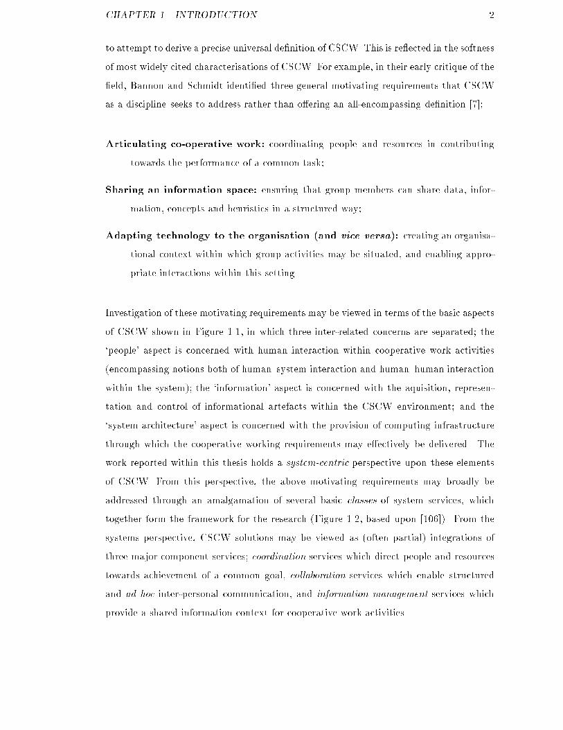
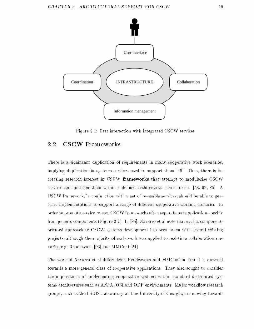
CHAPTER 1. INTRODUCTION 2to attempt to derive a precise universal de�nition of CSCW. This is re ected in the softnessof most widely cited characterisations of CSCW. For example, in their early critique of the�eld, Bannon and Schmidt identi�ed three general motivating requirements that CSCWas a discipline seeks to address rather than o�ering an all-encompassing de�nition [7];Articulating co-operative work: coordinating people and resources in contributingtowards the performance of a common task;Sharing an information space: ensuring that group members can share data, infor-mation, concepts and heuristics in a structured way;Adapting technology to the organisation (and vice versa): creating an organisa-tional context within which group activities may be situated, and enabling appro-priate interactions within this setting.Investigation of these motivating requirements may be viewed in terms of the basic aspectsof CSCW shown in Figure 1.1, in which three inter-related concerns are separated; the`people' aspect is concerned with human interaction within cooperative work activities(encompassing notions both of human{system interaction and human{human interactionwithin the system); the `information' aspect is concerned with the aquisition, represen-tation and control of informational artefacts within the CSCW environment; and the`system architecture' aspect is concerned with the provision of computing infrastructurethrough which the cooperative working requirements may e�ectively be delivered. Thework reported within this thesis holds a system-centric perspective upon these elementsof CSCW. From this perspective, the above motivating requirements may broadly beaddressed through an amalgamation of several basic classes of system services, whichtogether form the framework for the research (Figure 1.2, based upon [106]). From thesystems perspective, CSCW solutions may be viewed as (often partial) integrations ofthree major component services; coordination services which direct people and resourcestowards achievement of a common goal, collaboration services which enable structuredand ad hoc inter-personal communication, and information management services whichprovide a shared information context for cooperative work activities.

CHAPTER 1. INTRODUCTION 3Coordination Collaboration
Information Management
INFRASTRUCTUREFigure 1.2: System-centric aspects of computer-supported cooperative workSystems-centric CSCW research and development e�orts may be characterised throughcomparison of the relative emphasis placed upon supporting these basic constituent ser-vices. The research reported in this thesis has been motivated through collaboration be-tween the Centre for Virtual Working Environments (CVWE) at The University of Leedsand the Intelligent Business Systems Group (IBS) at BT Laboratories. The CVWE andIBS groups are focused on di�erent research goals and application domains but thereis a mutual interest in systems-support for coordination of distributed cooperative workactivities. Within the general system-centric view of CSCW systems presented in Figure1.2, research within the IBS group may informally be positioned towards the left side ofthe diagram, whereas the problem domain under investigation within the CVWE appearstowards the right side of the diagram. There is however increasing research interest inholistic approaches towards supporting group work, in which traditionally disjoint process-oriented and ad-hoc collaboration-centric approaches are beginning to converge towardsintegrated work management solutions (e.g. [106]). This thesis attempts to contribute tounderstanding within this middle-ground area through an investigation of the contrasting,yet orthogonal, VWS and IBS approaches. These two approaches are described in Section1.1 and Section 1.2 respectively. Section 1.3 then outlines the investigative domain forthe research, leading to the identi�cation of speci�c research hypotheses and objectivesin Section 1.4.

CHAPTER 1. INTRODUCTION 41.1 Virtual Working SystemsThe Centre for Virtual Working Environments at the University of Leeds brings togetheran inter-disciplinary team of social and computer scientists investigating a class of CSCWenvironment referred to as Virtual Working Environments (VWE). A Virtual WorkingEnvironment is characterised by the group as a working environment� where people can undertake focused work;� within a rich information space;� based on familiar working metaphors;� free from the need for physical co-location;� delivered via internet technologies.Virtual Working Systems (VWSs) are internet computing systems which create VWEsthrough the integration of a range of component services and technologies, e.g.� information integration and knowledge services;� search, navigation and reporting services;� document management services;� collaboration services;� security services.Implementations of these core VWS services are modularised and con�gured on a perapplication basis, using a layered software framework to guide development. Before de-scribing this framework and the generalised VWS services provided within it, it is useful toconsider a concrete exemplar of a VWS implementation|the University of Leeds VirtualScience Park.
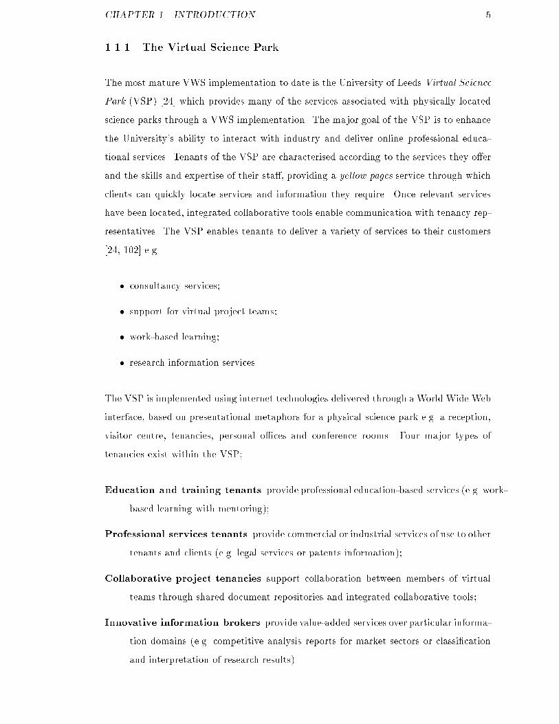
CHAPTER 1. INTRODUCTION 51.1.1 The Virtual Science ParkThe most mature VWS implementation to date is the University of Leeds Virtual SciencePark (VSP) [24] which provides many of the services associated with physically locatedscience parks through a VWS implementation. The major goal of the VSP is to enhancethe University's ability to interact with industry and deliver online professional educa-tional services. Tenants of the VSP are characterised according to the services they o�erand the skills and expertise of their sta�, providing a yellow pages service through whichclients can quickly locate services and information they require. Once relevant serviceshave been located, integrated collaborative tools enable communication with tenancy rep-resentatives. The VSP enables tenants to deliver a variety of services to their customers[24, 102] e.g.� consultancy services;� support for virtual project teams;� work-based learning;� research information services.The VSP is implemented using internet technologies delivered through a World Wide Webinterface, based on presentational metaphors for a physical science park e.g. a reception,visitor centre, tenancies, personal o�ces and conference rooms. Four major types oftenancies exist within the VSP;Education and training tenants provide professional education-based services (e.g. work-based learning with mentoring);Professional services tenants provide commercial or industrial services of use to othertenants and clients (e.g. legal services or patents information);Collaborative project tenancies support collaboration between members of virtualteams through shared document repositories and integrated collaborative tools;Innovative information brokers provide value-added services over particular informa-tion domains (e.g. competitive analysis reports for market sectors or classi�cationand interpretation of research results).
CHAPTER 1. INTRODUCTION 6The conceptual map of the VSP is shown in Figure 1.3. It should be noted, however,that although the VSP (and other VWS implementations) are delivered through physicalmetaphors they are not currently virtual reality applications. The technologies for de-livering virtual reality VWS implementations are now �ltering into the marketplace, butthe bene�ts of adopting such mechanisms are not yet su�ciently understood to warrantdetailed investigation. Instead of virtual reality implementations, the VSP and associatedVWS implementations provide hybrid interfaces based upon HTML and 2D image-maprepresentations of the physical organisational space. For example, Figure 1.4 shows apersonal o�ce area within a VSP tenancy.Visitorcentre
Knowledgeservices
Innovativeinformation
brokers
Educationand
training
Professionalservices
Collaborativeprojecttenancy
Access to tenancies
Access to tenancies
VSP WWW presence
TenancyWWWpresence
Figure 1.3: Tenancy navigation within the Virtual Science Park1.1.2 The VWS framework and core servicesThe VWS software system, within which the VSP is implemented, integrates core VWSservices through internet delivery mechanisms. However, VWS implementations are notspeci�cally designed for the public Internet. The provision of private corporate network(intranet) VWS solutions is also of importance to the group.1 Within an Internet context,VWS services may be regarded as value-added services that are layered above standardInternet and network services as shown in Figure 1.5.1Within this thesis the term internet is used to mean either Internet or intranet. VWS solutions forthese network domains would be di�erentiated primarily by their access control requirements. Such factorsare inconsequential to this work and the existence of an appropriate security service is therefore assumed.

CHAPTER 1. INTRODUCTION 7
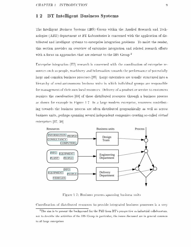
Figure 1.4: VSP personal o�ce ( c 1998 University of Leeds)A reference framework has been adopted by the group using an architectural style withinwhich services are positioned into functional layers, as shown in Figure 1.6. The frameworkis largely based upon Wiederhold's I3 (Intelligent Integration of Information) architecture[116]. The function of each layer is summarised below.The information integration layer maps heterogeneous domain information sourcesinto a consistent information space. For existing VWS implementations, the informationspace describes member organisations and the services they provide through the expertiseand skills of their sta�. This e�ectively provides an organisational context within whichcollaborative work is situated [6].Information mediation layer components are responsible for providing semantic in-terpretation services over the information space. In the current VWS implementations,mediation is provided via multiple classi�cation schemes that serve as simple domainontologies. Future work within the group aims to incorporate intelligent software compo-
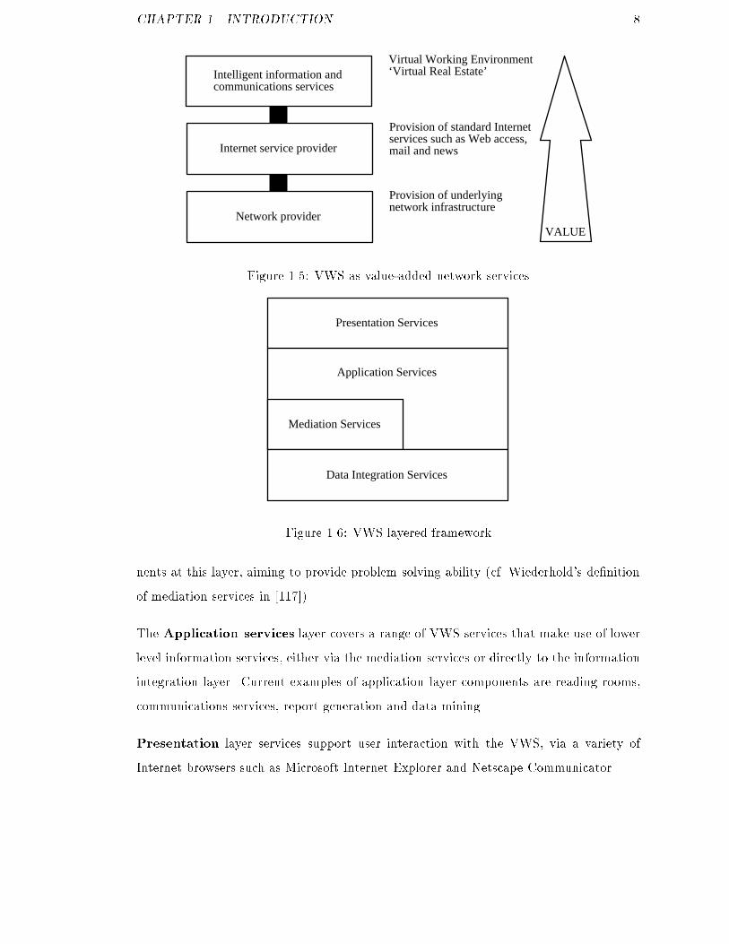
CHAPTER 1. INTRODUCTION 8Network provider
Internet service provider
Intelligent information andcommunications services
Provision of underlyingnetwork infrastructure
Provision of standard Internetservices such as Web access,mail and news
Virtual Working Environment‘Virtual Real Estate’
VALUEFigure 1.5: VWS as value-added network servicesPresentation Services
Mediation Services
Application Services
Data Integration ServicesFigure 1.6: VWS layered frameworknents at this layer, aiming to provide problem solving ability (cf. Wiederhold's de�nitionof mediation services in [117]).The Application services layer covers a range of VWS services that make use of lowerlevel information services, either via the mediation services or directly to the informationintegration layer. Current examples of application layer components are reading rooms,communications services, report generation and data mining.Presentation layer services support user interaction with the VWS, via a variety ofInternet browsers such as Microsoft Internet Explorer and Netscape Communicator.
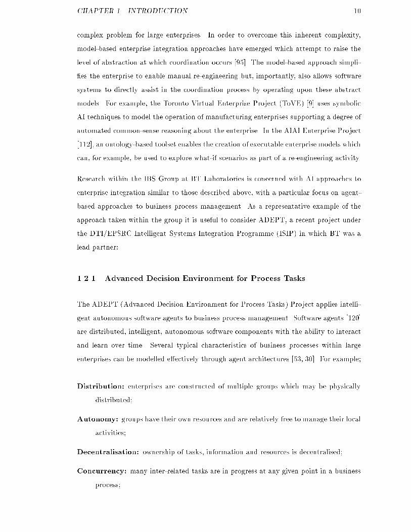
CHAPTER 1. INTRODUCTION 91.2 BT Intelligent Business SystemsThe Intelligent Business Systems (IBS) Group within the Applied Research and Tech-nologies (ART) department at BT Laboratories is concerned with the application of dis-tributed and intelligent systems to enterprise integration problems. To assist the reader,this section provides an overview of enterprise integration and related research e�ortswith a focus on approaches that are relevant to the IBS Group.2Enterprise integration (EI) research is concerned with the coordination of enterprise re-sources such as people, machinery and information towards the performance of potentiallylarge and complex business processes [95]. Large enterprises are usually structured into ahierarchy of semi-autonomous business units in which individual groups are responsiblefor management of their own local resources. Delivery of a product or service to customersrequires the coordination [68] of these distributed resources through a business processas shown for example in Figure 1.7. In a large modern enterprise, resources contribut-ing towards the business process are often distributed geographically as well as acrossbusiness units, perhaps spanning several independent companies creating so-called virtualenterprises [37, 38].DesignTeam
EngineeringDepartment
DeliveryDepartment
ProcessBusiness unitsResources
PEOPLE
INFOEQUIPMENT
PEOPLE
INFO
INFORMATION
VEHICLES
PLANT
COMPUTERS
EQUIPMENT
CONSULTANCYPEOPLE
Figure 1.7: Business process spanning business unitsCoordination of distributed resources to provide integrated business processes is a very2The aim is to present the background for the PhD from BT's perspective as industrial collaborators,not to describe the activities of the IBS Group in particular; the issues discussed are in general commonto all large enterprises.
CHAPTER 1. INTRODUCTION 10complex problem for large enterprises. In order to overcome this inherent complexity,model-based enterprise integration approaches have emerged which attempt to raise thelevel of abstraction at which coordination occurs [95]. The model-based approach simpli-�es the enterprise to enable manual re-engineering but, importantly, also allows softwaresystems to directly assist in the coordination process by operating upon these abstractmodels. For example, the Toronto Virtual Enterprise Project (ToVE) [9] uses symbolicAI techniques to model the operation of manufacturing enterprises supporting a degree ofautomated common-sense reasoning about the enterprise. In the AIAI Enterprise Project[112], an ontology-based toolset enables the creation of executable enterprise models whichcan, for example, be used to explore what-if scenarios as part of a re-engineering activity.Research within the IBS Group at BT Laboratories is concerned with AI approaches toenterprise integration similar to those described above, with a particular focus on agent-based approaches to business process management. As a representative example of theapproach taken within the group it is useful to consider ADEPT, a recent project underthe DTI/EPSRC Intelligent Systems Integration Programme (ISIP) in which BT was alead partner:1.2.1 Advanced Decision Environment for Process TasksThe ADEPT (Advanced Decision Environment for Process Tasks) Project applies intelli-gent autonomous software agents to business process management. Software agents [120]are distributed, intelligent, autonomous software components with the ability to interactand learn over time. Several typical characteristics of business processes within largeenterprises can be modelled e�ectively through agent architectures [53, 30]. For example;Distribution: enterprises are constructed of multiple groups which may be physicallydistributed;Autonomy: groups have their own resources and are relatively free to manage their localactivities;Decentralisation: ownership of tasks, information and resources is decentralised;Concurrency: many inter-related tasks are in progress at any given point in a businessprocess;

CHAPTER 1. INTRODUCTION 11Unpredictability: processes often cannot be completely speci�ed a priori and may bea�ected whilst in progress through new instructions or error conditions.Within ADEPT, a cooperative agent architecture was developed that enables businessprocesses to be represented as a community of negotiating agents (Figure 1.8). A centralconcept in the ADEPT architecture is that of a service, representing some abstraction ofproblem solving endeavour [53]. Agents within ADEPT are responsible for negotiating forsupply and consumption of services with other agents within the community. Agents maythemselves be comprised of subsidiary agents under their control enabling hierarchicalorganisational structures to be modelled.======
IBM PC
===============
Macintosh IIfx
@@@@@@@@@@@@@@@@
@@@@@@@@@
@@@@@@@@@
222222222222222222222222222222222222222222222222222222
Information Sharing
Marketing Team Design Team
Sales Team
Legal department
NegotiationProtocol
ServiceLevelAgreements
Services
Intelligent AgentFigure 1.8: The business process as a community of negotiating agentsThere are three major phases to the service lifecycle within ADEPT [53] (Figure 1.9).During the creation phase, services are modelled using a special purpose language calledService Description Language (SDL). SDL de�nes the inputs, outputs and components fora particular service using a declarative representation. Secondly, Service Level Agreement(SLA) templates are created that de�ne the parameters over which agents may negotiateservice delivery. At the second phase, agents negotiate for delivery of instances of ser-vices in a process referred to as provisioning. The �nal phase in the service lifecycle isthe management of service delivery and dynamic re-negotiation of SLAs should this benecessary.Agents within ADEPT are general purpose in the sense that they are not explicitly de-signed to manage speci�c services. Instead, the same basic agent shell may be loaded
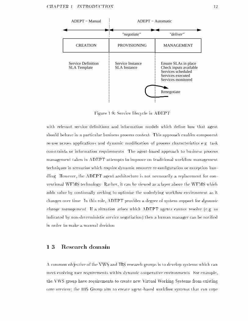
CHAPTER 1. INTRODUCTION 12CREATION PROVISIONING MANAGEMENT
Service DefinitionSLA Template
Service InstanceSLA Instance
Ensure SLAs in placeCheck inputs availableServices scheduledServices executedServices monitored
Renegotiate
ADEPT − Manual ADEPT − Automatic
"negotiate" "deliver"
Figure 1.9: Service lifecycle in ADEPTwith relevant service de�nitions and information models which de�ne how that agentshould behave in a particular business process context. This approach enables componentre-use across applications and dynamic modi�cation of process characteristics e.g. taskconstraints or information requirements. The agent-based approach to business processmanagement taken in ADEPT attempts to improve on traditional work ow managementtechniques in scenarios which require dynamic resource re-con�guration or exception han-dling. However, the ADEPT agent architecture is not necessarily a replacement for con-ventional WFMS technology. Rather, it can be viewed as a layer above the WFMS whichadds value by continually seeking to optimise the underlying work ow environment as itchanges over time. In this role, ADEPT provides a degree of system support for dynamicchange management. If a situation arises which ADEPT agents cannot resolve (e.g. asindicated by non-deterministic service negotiation) then a human manager can be noti�edin order to make a manual decision.1.3 Research domainA common objective of the VWS and IBS research groups is to develop systems which canmeet evolving user requirements within dynamic cooperative environments. For example,the VWS group have requirements to create new Virtual Working Systems from existingcore services; the IBS Group aim to create agent-based work ow systems that can cope
CHAPTER 1. INTRODUCTION 13with dynamic changes in business process characteristics. Within these environments, thebasic requirement is to design and build software systems in such a way that the cost ofiterative development and maintenance is minimised as systems evolve. This requirementmight be stated informally as the need to \engineer for change."As discussed earlier, VWS solutions support ad hoc human to human collaboration withinmanaged information spaces. This loose coordination style contrasts with the process-centric IBS approach to work management in which software agents dynamically controlevolving business activities. One area of mutual research interest between the VWS andIBS groups is the intersection of these people-centric and process-centric approaches,towards deriving systems that provide exible collaborative support for people engagedin business processes within dynamic enterprise environments.Virtual Working Systems have been developed primarily to support delivery of high-quality educational and research knowledge services. The broad goal of enterprise inte-gration e�orts (under which IBS may be classi�ed) is to bring together enterprise resources(such as people, information and computing technologies) in an e�ective manner to create exible work processes that evolve as the enterprise environment changes. The informa-tion and collaboration services provided by Virtual Working Systems could be of widerbene�t within dynamic enterprises if they could be appropriately packaged and redeployedwithin their systems environments. The collaboration between the IBS group at BT andVWS group at Leeds provided a good basis upon which to explore this basic idea.A further motivating factor which helped scope the problem was a desire to exploit theincreasing potential of Internet computing and the World Wide Web in supporting co-operative work within (and between) integrated enterprises. Initial implementations ofVirtual Working Systems were built through compiled languages on Unix workstations.Whilst such an approach proved adequate in demonstrating VWS concepts, it was onlyafter switching development e�ort towards Web-based systems that commercial exploita-tion became feasible. It therefore seemed appropriate to investigate the application ofthese services within a wider context, given e.g. the ubiquity of the Web computing plat-form on a global scale; the increasing internal use of Internet technologies within largeenterprises; the emergence of Web-based collaboration and coordination products.
CHAPTER 1. INTRODUCTION 141.4 Research problemThe target users for this research are software engineers responsible for building and main-taining Internet-based cooperative systems within dynamic application environments.When creating systems, engineers must bring together required component CSCW ser-vices and integrate these into a coherent application delivered via Web infrastructure.Such systems are referred to in this thesis as integrated internet CSCW systems. Softwareengineering methods based upon iterative system construction, evaluation and re�nementare very useful in creating usable systems through participatory design [61, 4]. However,development of cooperative Web information systems through rapid iterative cycles iscurrently di�cult, because of their complexity. The research reported within this thesisseeks to address three speci�c problems which currently prevent rapid prototyping andevolutionary development of integrated internet CSCW systems;1. CSCW services are not reusableMany cooperative work scenarios share similar requirements for basic CSCW ser-vices e.g. coordination, collaboration, information management etc. yet signi�cantduplication of functionality can often be observed across CSCW applications usedwithin enterprises, increasing maintenance complexity and potentially introducingdata consistency and synchronisation problems [6, 45]. Component reusability is akey rapid prototyping enabler [57], but no such component architectures exist forWeb-based CSCW systems.2. User perspectives are not adequately re ected during prototypingCooperative working scenarios often involve participants who possess di�erent per-spectives upon their common activity [40]. Participatory design of cooperativesystems through prototypes should re ect this heterogeneity but, because of theinherent complexity of the systems, it is di�cult to quickly produce new iterationsthat adequately embody emerging requirements from the user community.3. Evolving requirements are not adequately re ected in evolving live sys-temsUser requirements change over time of course, and these changes must be re ectedback into an evolving system. However, due to the complexity of internet CSCWsystem implementations, changes typically cannot be a�ected as often, or at the

CHAPTER 1. INTRODUCTION 15�ne level of granularity that users desire because the required software engineeringe�ort outweighs the potential bene�t of the change.1.5 ContributionThe contribution of this work towards addressing the above research problems is to in-vestigate model-based architectural support for prototypical construction and subsequentmaintenance of integrated cooperative systems. The approach proposed within this thesismay brie y be summarised as follows. Firstly, application-speci�c code, reusable CSCWservices and user interface functionality are architecturally separated. Secondly, applica-tions are speci�ed at a high level of abstraction using a modelling language to describeuser interaction with applications and services via the user interface. Finally, a runtimesupport architecture driven by this model is provided through which access to application-speci�c code and reusable CSCW services are provided via dynamically generated Webuser interfaces.The feasibility of the approach was assessed through a proof-of-concept implementation ofa model-based CSCW toolkit called ParaDiMe, through which integrated internet CSCWsystems may be constructed. The design of ParaDime (described in Chapter 3) extendsthe DiMe architecture [79] developed within the Virtual Working Environments Group atLeeds University. DiMe was initially developed as an automated user interface generationtool for the World Wide Web. ParaDiMe extends DiMe through support for a gener-alised distributed object model, which was provided via CORBA in the proof-of-conceptimplementation. This fundamental extension to DiMe enables ParaDiMe to provide in-teractive access to cooperative applications and the basic services from which they arecomposed. Several architectural components of ParaDime were constructed through thismechanism, summarised speci�cally as follows. A remote method invocation (RMI) ser-vice provides access to arbitrary distributed objects via static or dynamic interfaces. Aninformation manager component provides a standards-based architectural interface todistributed information sources. A forms processing subsystem provides mechanisms fordynamic generation of HTML forms interfaces and associated handler code within dis-tributed applications. Finally, a collaborative tools subsystem supports execution andsession control of synchronous groupware applications. These component subsystems

CHAPTER 1. INTRODUCTION 16were integrated into a prototype application built using the ParaDiMe architecture. Thework ow helper prototype (described in Chapter 4) was built in order to investigate thepractical application of the proposed model-based approach to a case study cooperativeworking scenario.The broad hypothesis explored within this thesis is that the proposed model-based ap-proach can o�er a solution to the research problems identi�ed previously. Hence, threespeci�c research objectives may be identi�ed;1. To investigate how common requirements in cooperative working scenarios are metby reusable CSCW services and how such services can be brought to together in astructured manner which promotes their integration and reuse within a model-basedarchitecture;2. To assess the bene�t of a model-based approach towards system development throughrapid prototyping, to test the hypothesis that the approach reduces prototype de-velopment cycle times thereby enabling a higher level of user participation in thedesign process.3. To assess the bene�t of a model-based approach towards maintenance of systemsas user requirements evolve within live applications, to test the hypothesis that theapproach reduces the software e�ort required to a�ect changes thereby enablingevolving user requirements to be more e�ciently fed back into systems.1.6 Thesis structureChapter 2 (Architectural support for CSCW) investigates CSCW services and theirintegration and reuse within a exible CSCW system architecture. A number of ex-isting CSCW frameworks are introduced, leading to the identi�cation of a numberof core CSCW service classes of central interest to this research. Relevant researchand development e�orts are then surveyed within this classi�cation and a simpleCSCW framework is derived which serves to guide system design.Chapter 3 (Model-based CSCW architecture) speci�es the detailed design for amodel-based internet CSCW system architecture called ParaDiMe, which attempts

CHAPTER 1. INTRODUCTION 17to o�er a solution to the research problems.Chapter 4 (Case study implementation) describes a proof-of-concept implementa-tion used to explore the research approach, through application towards an exemplarcooperative working scenario within a large telecommunications enterprise.Chapter 5 (Critique) presents a critique of the research hypotheses through assess-ment of the architecture and proof-of-concept implementation.Chapter 6 (Conclusions and future work) reviews the contribution of the thesis ando�ers an outlook upon directions in which the research might be progressed.

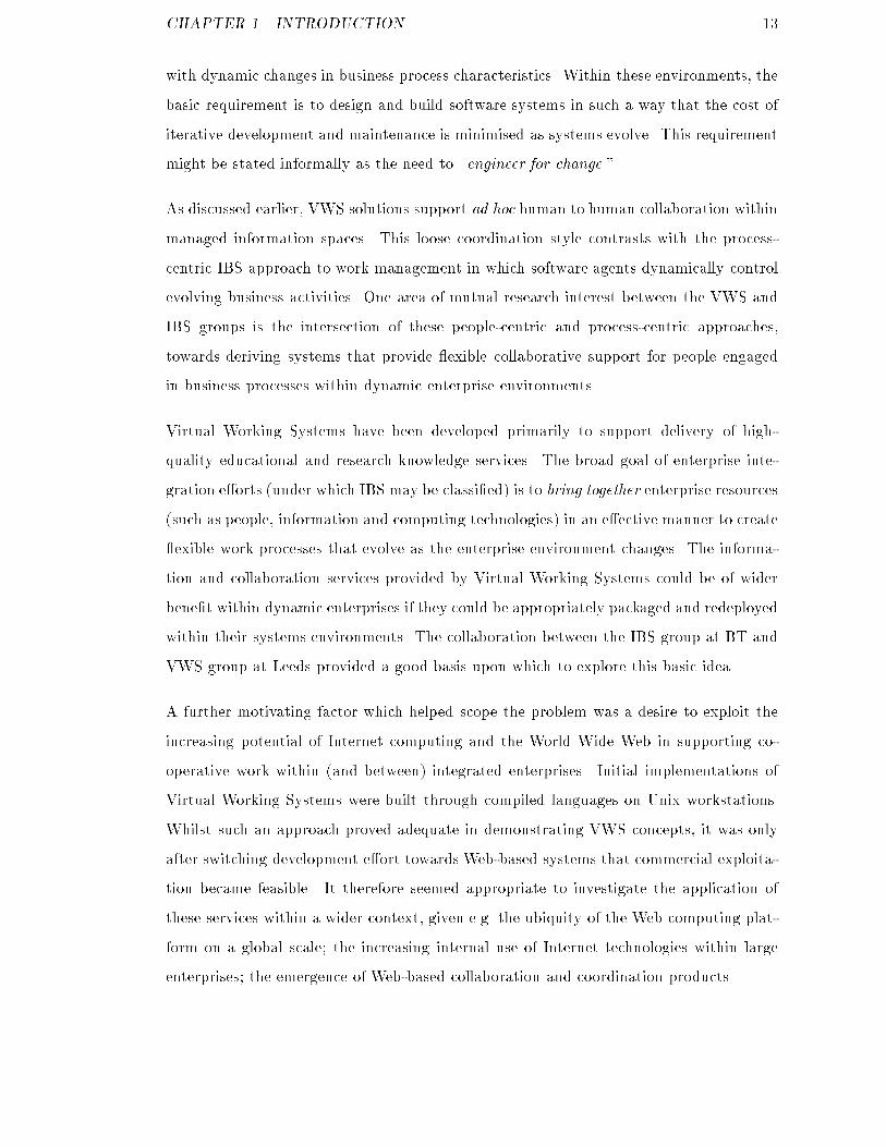
Chapter 2Architectural support for CSCW2.1 IntroductionThe broad goal in this work is to investigate structured construction techniques for in-tegrated internet CSCW systems. That is, CSCW systems that integrate a number ofcomponent services and are delivered via internet infrastructure. The motivation for inte-gration of services, rather than re-implementation, is in simplifying systems developmentand reusing existing system components rather than duplicating software engineeringe�orts. Chapter 1 provided a high-level systems perspective upon cooperative work. Ex-tending this simple model to explicitly include user interaction services provides a basicclassi�cation through which related work may be discussed (Figure 2.1).Before considering these individual classes of CSCW services, however, it is useful to intro-duce existing CSCW frameworks which attempt to bring services together in a structuredway. Section 2.2 discusses several existing and emerging CSCW frameworks that areof relevance to this work. Section 2.3 then discusses CSCW services according to the�ve basic CSCW architecture elements shown in Figure 2.1 (coordination, collaboration,information management, user interface and infrastructure).18
CHAPTER 2. ARCHITECTURAL SUPPORT FOR CSCW 19Coordination Collaboration
Information management
INFRASTRUCTURE
User interface
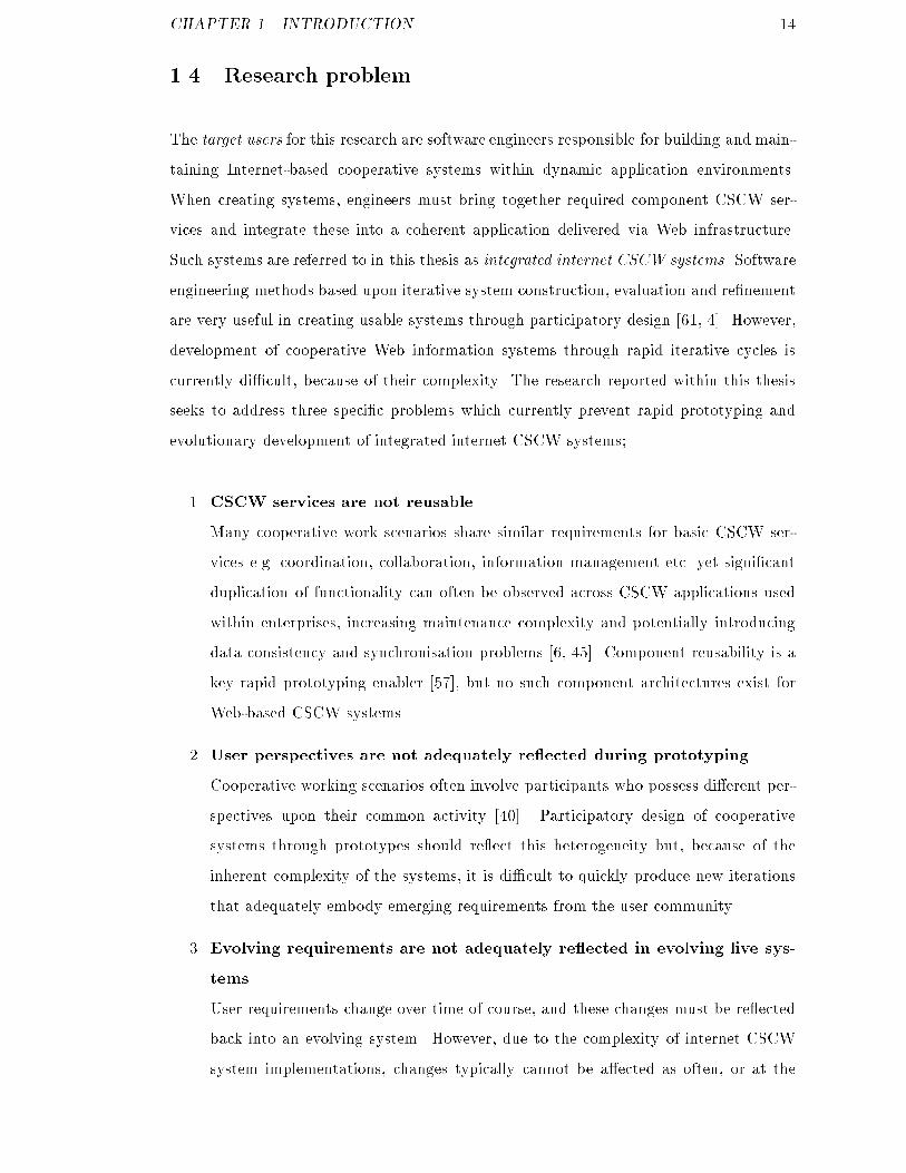
Figure 2.1: User interaction with integrated CSCW services2.2 CSCW FrameworksThere is a signi�cant duplication of requirements in many cooperative work scenarios,implying duplication in systems services used to support them [45]. Thus, there is in-creasing research interest in CSCW frameworks that attempt to modularise CSCWservices and position them within a de�ned architectural structure e.g. [58, 92, 85]. ACSCW framework, in conjunction with a set of re-usable services, should be able to gen-erate implementations to support a range of di�erent cooperative working scenarios. Inorder to promote service re-use, CSCW frameworks often separate out application-speci�cfrom generic components (Figure 2.2). In [85], Navarro et al note that such a component-oriented approach to CSCW systems development has been taken with several existingprojects, although the majority of early work was applied to real-time collaboration sce-narios e.g. Rendezvous [93] and MMConf [21].The work of Navarro et al di�ers from Rendezvous and MMConf in that it is directedtowards a more general class of cooperative applications. They also sought to considerthe implications of implementing cooperative systems within standard distributed sys-tems architectures such as ANSA, OSI and ODP environments. Major work ow researchgroups, such as the LSDIS Laboratory at The University of Georgia, are moving towards
CHAPTER 2. ARCHITECTURAL SUPPORT FOR CSCW 20CSCW
APPCSCW
APPCSCW
APP
CSCW Framework
CSCW Services
CSCWAPP
Service
Service
Service
CSCWAPP
Service
Service
ServiceCSCW
APP
Service
Service
Service
Unintegrated CSCW applications CSCW applications integrated viaa CSCW framework
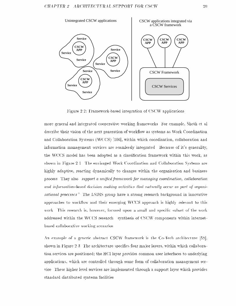
Figure 2.2: Framework-based integration of CSCW applicationsmore general and integrated cooperative working frameworks. For example, Sheth et aldescribe their vision of the next generation of work ow as systems as Work Coordinationand Collaboration Systems (WCCS) [106], within which coordination, collaboration andinformation management services are seamlessly integrated. Because of it's generality,the WCCS model has been adopted as a classi�cation framework within this work, asshown in Figure 2.1. The envisaged Work Coordination and Collaboration Systems arehighly adaptive, reacting dynamically to changes within the organisation and businessprocess. They also \support a uni�ed framework for managing coordination, collaborationand information-based decision making activities that naturally occur as part of organi-sational processes." The LSDIS group have a strong research background in innovativeapproaches to work ow and their emerging WCCS approach is highly relevant to thiswork. This research is, however, focused upon a small and speci�c subset of the workaddressed within the WCCS research|synthesis of CSCW components within internet-based collaborative working scenarios.An example of a generic abstract CSCW framework is the Co-Tech architecture [58],shown in Figure 2.3. The architecture speci�es four major layers, within which collabora-tion services are positioned; the HCI layer provides common user interfaces to underlyingapplications, which are controlled through some form of collaboration management ser-vice. These higher level services are implemented through a support layer which providesstandard distributed systems facilities.
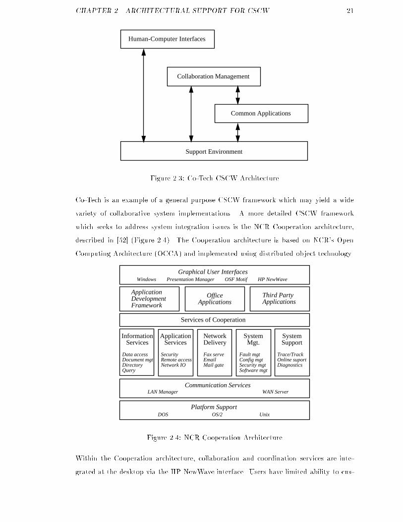
CHAPTER 2. ARCHITECTURAL SUPPORT FOR CSCW 21Support Environment
Human-Computer Interfaces
Collaboration Management
Common ApplicationsFigure 2.3: Co-Tech CSCW ArchitectureCo-Tech is an example of a general purpose CSCW framework which may yield a widevariety of collaborative system implementations. A more detailed CSCW frameworkwhich seeks to address system integration issues is the NCR Cooperation architecture,described in [52] (Figure 2.4). The Cooperation architecture is based on NCR's OpenComputing Architecture (OCCA) and implemented using distributed object technology.Information
Services
Data accessDocument mgtDirectoryQuery
Services of Cooperation
Graphical User InterfacesWindows Presentation Manager OSF Motif HP NewWave
ApplicationServices
SecurityRemote accessNetwork IO
NetworkDelivery
Fax serveEmailMail gate
SystemMgt.
Fault mgtConfig mgtSecurity mgtSoftware mgt
SystemSupport
Trace/TrackOnline suportDiagnostics
Communication ServicesLAN Manager WAN Server
Platform SupportDOS OS/2 Unix
Third PartyApplications
OfficeApplications
Application DevelopmentFramework
Figure 2.4: NCR Cooperation ArchitectureWithin the Cooperation architecture, collaboration and coordination services are inte-grated at the desktop via the HP NewWave interface. Users have limited ability to cus-
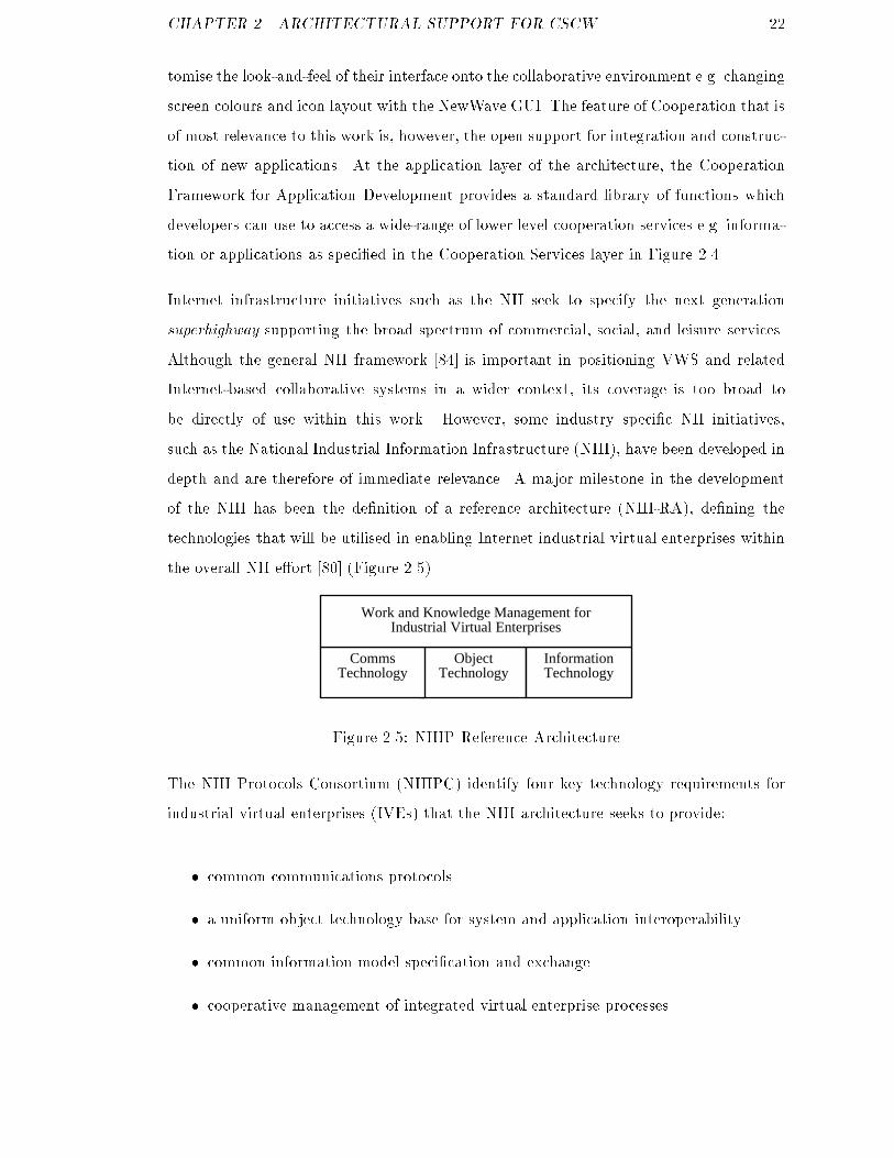
CHAPTER 2. ARCHITECTURAL SUPPORT FOR CSCW 22tomise the look-and-feel of their interface onto the collaborative environment e.g. changingscreen colours and icon layout with the NewWave GUI. The feature of Cooperation that isof most relevance to this work is, however, the open support for integration and construc-tion of new applications. At the application layer of the architecture, the CooperationFramework for Application Development provides a standard library of functions whichdevelopers can use to access a wide-range of lower level cooperation services e.g. informa-tion or applications as speci�ed in the Cooperation Services layer in Figure 2.4.Internet infrastructure initiatives such as the NII seek to specify the next generationsuperhighway supporting the broad spectrum of commercial, social, and leisure services.Although the general NII framework [84] is important in positioning VWS and relatedInternet-based collaborative systems in a wider context, its coverage is too broad tobe directly of use within this work. However, some industry speci�c NII initiatives,such as the National Industrial Information Infrastructure (NIII), have been developed indepth and are therefore of immediate relevance. A major milestone in the developmentof the NIII has been the de�nition of a reference architecture (NIII-RA), de�ning thetechnologies that will be utilised in enabling Internet industrial virtual enterprises withinthe overall NII e�ort [80] (Figure 2.5).Comms
TechnologyObject
TechnologyInformationTechnology
Work and Knowledge Management forIndustrial Virtual EnterprisesFigure 2.5: NIIIP Reference ArchitectureThe NIII Protocols Consortium (NIIIPC) identify four key technology requirements forindustrial virtual enterprises (IVEs) that the NIII architecture seeks to provide:� common communications protocols� a uniform object technology base for system and application interoperability� common information model speci�cation and exchange� cooperative management of integrated virtual enterprise processes
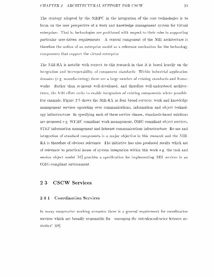
CHAPTER 2. ARCHITECTURAL SUPPORT FOR CSCW 23The strategy adopted by the NIIIPC in the integration of the core technologies is tofocus on the user perspective of a work and knowledge management system for virtualenterprises. That is, technologies are positioned with respect to their roles in supportingparticular user-driven requirements. A central component of the NIII architecture istherefore the notion of an enterprise model as a reference mechanism for the technologycomponents that support the virtual enterprise.The NIII-RA is notable with respect to this research in that it is based heavily on theintegration and interoperability of component standards. Within industrial applicationdomains (e.g. manufacturing) there are a large number of existing standards and frame-works. Rather than re-invent well-developed, and therefore well-understood architec-tures, the NIII e�ort seeks to enable integration of existing components where possible.For example, Figure 2.5 shows the NIII-RA as four broad services; work and knowledgemanagement services operating over communications, information and object technol-ogy infrastructure. In specifying each of these service classes, standards-based solutionsare proposed e.g. WFMC compliant work management, OMG compliant object services,STEP information management and Internet communications infrastructure. Re-use andintegration of standard components is a major objective in this research and the NIII-RA is therefore of obvious relevance. The initiative has also produced results which areof relevance to practical issues of system integration within this work e.g. the task andsession object model [81] provides a speci�cation for implementing NIII services in anOMG-compliant environment.2.3 CSCW Services2.3.1 Coordination ServicesIn many cooperative working scenarios there is a general requirement for coordinationservices which are broadly responsible for \managing the interdependencies between ac-tivities" [68].
CHAPTER 2. ARCHITECTURAL SUPPORT FOR CSCW 24Jayachandra identi�es �ve key properties that must be analysed in order to achieve processcoordination [52]Objectives: what is the purpose of the activity to be performed?Activities: how can this purpose be expressed as an ordered sequence or functionallydecomposed set of subtasks?Performers: what skills/expertise are required to perform the above subtasks and howshould these be mapped?Interdependencies: what constraints exist between activities that comprise the busi-ness process?Resource allocation: what resources are required at each stage of the process?Work ow management solutions provide automated assistance for speci�cation of businessprocesses according to the above general criteria. These speci�cations are then used todrive work ow engines which enable multiple users to collectively enact the businessprocess. Several hundred commercial products claim to support some kind of work owmanagement functionality [106]. Whilst it is beyond the scope of this thesis to comparethe entire range of existing systems,1 most implementations may be classi�ed accordingto their level of support for three basic work ow types [105];administrative work ows involve coordination of simple, predictable, repetitive activi-ties e.g. expenses claims processing;ad hoc work ows involve human coordination, collaboration and co-decision e.g. soft-ware development projects;production work ows involve predictable repetitive processes which require structuredaccess to enterprise information systems e.g. insurance claims processing, telephonesales.It should, however, be noted that the the above work ow classes are not mutually exclu-sive. Thus, there is increasing interest in supporting hybrid work ow scenarios within the1Sheth cites a number of papers providing commercial work ow product surveys in [106, p. 3].
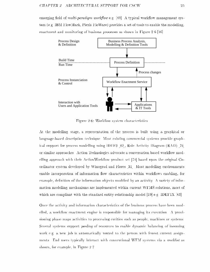
CHAPTER 2. ARCHITECTURAL SUPPORT FOR CSCW 25emerging �eld of multi-paradigm work ow e.g. [89]. A typical work ow management sys-tem (e.g. IBM FlowMark, Plexis FloWare) provides a set of tools to enable the modelling,enactment and monitoring of business processes as shown in Figure 2.6 [46].Business Process Analysis,
Modelling & Definition Tools
Process Definition
Workflow Enactment Service
Applications & IT Tools
Build TimeRun Time
Process changes
Interaction withUsers and Application Tools
Process Instanciation& Control
Process Design& Definition
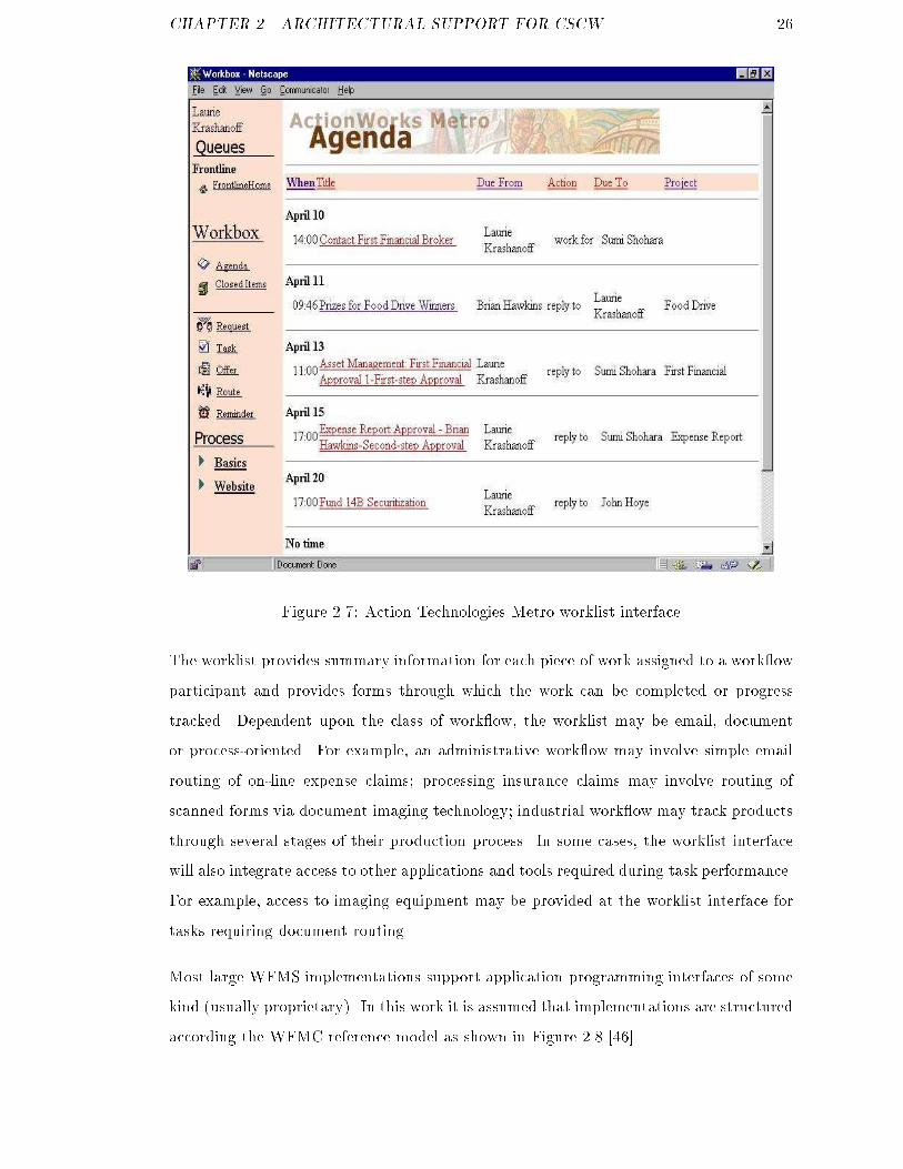
Figure 2.6: Work ow system characteristicsAt the modelling stage, a representation of the process is built using a graphical orlanguage-based description technique. Most existing commercial systems provide graph-ical support for process modelling using IDEF0 [82], Role Activity Diagram (RAD) [76]or similar approaches. Action Technologies advocate a conversation based work ow mod-elling approach with their ActionWork ow product set [74] based upon the original Co-ordinator system developed by Winograd and Flores [31]. Most modelling environmentsenable incorporation of information ow characteristics within work ows enabling, forexample, de�nition of the information objects modi�ed by an activity. A variety of infor-mation modelling mechanisms are implemented within current WFMS solutions, most ofwhich are compliant with the standard entity-relationship model [19] e.g. IDEF1X [83].Once the activity and information characteristics of the business process have been mod-elled, a work ow enactment engine is responsible for managing its execution. A provi-sioning phase maps activities to processing entities such as people, machines or systems.Several systems support pooling of resources to enable dynamic balancing of incomingwork e.g. a new job is automatically routed to the person with fewest current assign-ments. End users typically interact with conventional WFM systems via a worklist asshown, for example, in Figure 2.7.
CHAPTER 2. ARCHITECTURAL SUPPORT FOR CSCW 26
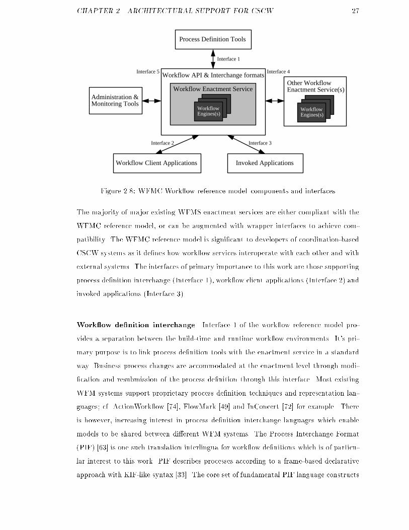
Figure 2.7: Action Technologies Metro worklist interfaceThe worklist provides summary information for each piece of work assigned to a work owparticipant and provides forms through which the work can be completed or progresstracked. Dependent upon the class of work ow, the worklist may be email, documentor process-oriented. For example, an administrative work ow may involve simple emailrouting of on-line expense claims; processing insurance claims may involve routing ofscanned forms via document imaging technology; industrial work ow may track productsthrough several stages of their production process. In some cases, the worklist interfacewill also integrate access to other applications and tools required during task performance.For example, access to imaging equipment may be provided at the worklist interface fortasks requiring document routing.Most large WFMS implementations support application programming interfaces of somekind (usually proprietary). In this work it is assumed that implementations are structuredaccording the WFMC reference model as shown in Figure 2.8 [46].
CHAPTER 2. ARCHITECTURAL SUPPORT FOR CSCW 27Workflow Enactment Service
Workflow API & Interchange formats
WorkflowEngines(s)
WorkflowEngines(s)
Other WorkflowEnactment Service(s)
Interface 1
Interface 2 Interface 3
Interface 4Interface 5
Invoked ApplicationsWorkflow Client Applications
Administration &Monitoring Tools
Process Definition Tools
Figure 2.8: WFMC Work ow reference model{components and interfacesThe majority of major existing WFMS enactment services are either compliant with theWFMC reference model, or can be augmented with wrapper interfaces to achieve com-patibility. The WFMC reference model is signi�cant to developers of coordination-basedCSCW systems as it de�nes how work ow services interoperate with each other and withexternal systems. The interfaces of primary importance to this work are those supportingprocess de�nition interchange (Interface 1), work ow client applications (Interface 2) andinvoked applications (Interface 3).Work ow de�nition interchange Interface 1 of the work ow reference model pro-vides a separation between the build-time and runtime work ow environments. It's pri-mary purpose is to link process de�nition tools with the enactment service in a standardway. Business process changes are accommodated at the enactment level through modi-�cation and resubmission of the process de�nition through this interface. Most existingWFM systems support proprietary process de�nition techniques and representation lan-guages; cf. ActionWork ow [74], FlowMark [49] and InConcert [72] for example. Thereis however, increasing interest in process de�nition interchange languages which enablemodels to be shared between di�erent WFM systems. The Process Interchange Format(PIF) [63] is one such translation interlingua for work ow de�nitions which is of particu-lar interest to this work. PIF describes processes according to a frame-based declarativeapproach with KIF-like syntax [33]. The core set of fundamental PIF language constructs
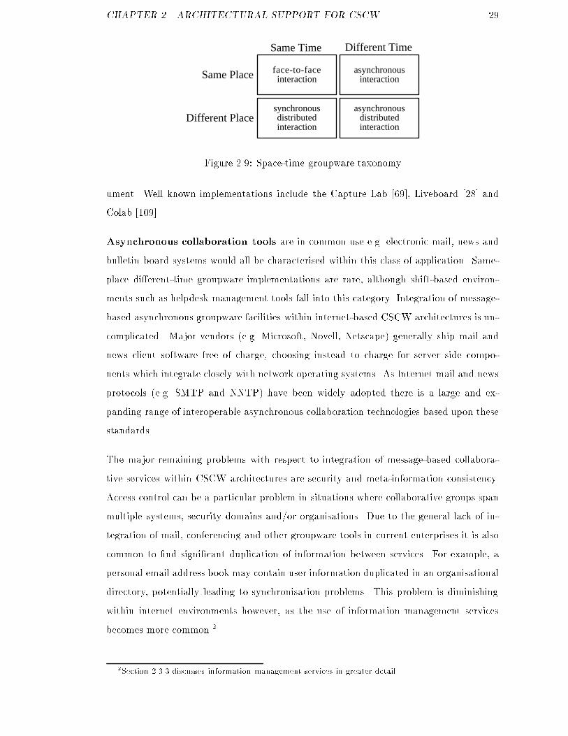
CHAPTER 2. ARCHITECTURAL SUPPORT FOR CSCW 28(e.g. describing activities and constraints between them) is self-extensible through a mech-anism of partially-shared views (PSVs) [64]. PSVs enable new concepts to be expressedin a PIF compliant way without violating the existing language.Work ow client interface Interface 2 provides a mechanism through which clientapplications can interact with the work ow engine. A worklist handler is the most com-mon type of client application, through which a human user is presented with tasks forcompletion. Some work ow systems provide API facilities which enable customised clientsoftware to be created but this usually requires programming changes to executable code.A exible approach taken in many newer work ow products is to provide Web access viaHTML forms interfaces e.g. Metro (Figure 2.7).Invoked applications interface Interface 3 de�nes an execution and control mecha-nism for sessions with applications invoked during a work ow session. There are manyconceivable examples of such applications although the most common usage scenario in-volves provision of access to enterprise information systems. For example, as part of agoods ordering work ow, access to a stock database management system might be pro-vided. This interface could also be used to manage access to collaborative working toolsas required within this research, although suitably exposed control interfaces would berequired of invoked groupware tools.2.3.2 Collaboration ServicesWithin a CSCW architecture, collaborative services provide system-mediated support forad hoc human-human interaction within the distributed environment. Johansen's space-time matrix is often used to classify implementations [54], as shown in Figure 2.9.Synchronous colocated collaboration tools support real-time face-to-face interac-tion. Most groupware implementations supporting this type of interaction are electronicmeeting room or group decision support systems, designed to aid group brainstormingsessions by overcoming problematic characteristics of conventional meetings e.g. poor oorcontrol, power struggles etc. Typical architectures provide each meeting participant witha workstation enabling (potentially anonymous) access to a shared whiteboard or doc-
CHAPTER 2. ARCHITECTURAL SUPPORT FOR CSCW 29Different Time
Same Place
Same Time
Different Place
face-to-faceinteraction
asynchronousinteraction
synchronousdistributedinteraction
asynchronousdistributedinteractionFigure 2.9: Space-time groupware taxonomyument. Well known implementations include the Capture Lab [69], Liveboard [28] andColab [109].Asynchronous collaboration tools are in common use e.g. electronic mail, news andbulletin board systems would all be characterised within this class of application. Same-place di�erent-time groupware implementations are rare, although shift-based environ-ments such as helpdesk management tools fall into this category. Integration of message-based asynchronous groupware facilities within internet-based CSCW architectures is un-complicated. Major vendors (e.g. Microsoft, Novell, Netscape) generally ship mail andnews client software free of charge, choosing instead to charge for server side compo-nents which integrate closely with network operating systems. As Internet mail and newsprotocols (e.g. SMTP and NNTP) have been widely adopted there is a large and ex-panding range of interoperable asynchronous collaboration technologies based upon thesestandards.The major remaining problems with respect to integration of message-based collabora-tive services within CSCW architectures are security and meta-information consistency.Access control can be a particular problem in situations where collaborative groups spanmultiple systems, security domains and/or organisations. Due to the general lack of in-tegration of mail, conferencing and other groupware tools in current enterprises it is alsocommon to �nd signi�cant duplication of information between services. For example, apersonal email address book may contain user information duplicated in an organisationaldirectory, potentially leading to synchronisation problems. This problem is diminishingwithin internet environments however, as the use of information management servicesbecomes more common.22Section 2.3.3 discusses information management services in greater detail.

CHAPTER 2. ARCHITECTURAL SUPPORT FOR CSCW 30Another important class of asynchronous groupware service are document manage-ment systems e.g. DocMan [5] and BCSCW [13]. Web-based implementations are be-coming increasingly popular as solutions can be created easily using standard infrastruc-ture services (e.g. Web servers, server access controls, document upload etc). A documentmanagement facility has proved to be one of the most popular features within VWS im-plementations. The reading room service, shown in Figure 2.10, enables VWS tenants oruser communities to create private repositories through which documents may be storedand exchanged.
Figure 2.10: VWS reading room ( c 1998 University of Leeds)Reading room services provide access controls on documents, enable version control forcollaborative authoring and can also check incoming material for viruses. Currently,reading rooms have to be set up by system support sta� on an individual basis. Once this

CHAPTER 2. ARCHITECTURAL SUPPORT FOR CSCW 31setup has taken place, however, nominated users may create new sub-folders and controlthe management of their own reading room areas.Synchronous distributed collaboration tools enable human-human communicationacross geographically separated spaces. One of the most successful initial research e�ortsin this area was the Media Spaces work at Xerox during the late 1980s [44]. The �rstgeneration of CSCW infrastructure projects were also directed towards support for syn-chronous distributed collaboration, notably Rendezvous (shared real-time interfaces) [93],Liza (shared user interface objects) [35] and Shared X (shared windowing) [43]. Relatedresearch work within the CVWE at Leeds University has investigated conference archi-tectures for use in Virtual Working Systems. In [48], Hunter proposes an architecturefor secure, user-centred conferencing within VWS implementations based upon the ITUH.323 and T.120 standards for audiovisual and data conferencing (Figure 2.11).33333333333333333333333333333333333333333333333333333333333333333333333333333333333333333333333333333333333333333333333333333333333333333333333333333333333333333333333333333333333333333333333333333333User
33333333333333333333333333333333333333333333333333333333333333333333333333333333333333333333333333333333333333333333333333333333333333333333333333333333
Virtual Working System
VWS Presentation Layer
InformationLayer
DocumentManagement
ConferencingServices
SecurityServices
IP Network
Conference ControlWebBrowser
T.120Support
H.323Support
Figure 2.11: VWS secure user-centred conferencing architectureAn initial implementation of this architecture integrates directory and security servicesto create a person-centric conferencing environment within a VWS based around Mi-crosoft's NetMeeting synchronous groupware product. NetMeeting facilitates audiovisualconferencing and application sharing within an internetwork environment. The work hasimportant implications for this research as it demonstrates how synchronous collaboration

CHAPTER 2. ARCHITECTURAL SUPPORT FOR CSCW 32services can be accessed within an integrated CSCW environment.2.3.3 Information Management ServicesMost cooperative working scenarios involve collaboration over shared information arte-facts. Services that manage access to such artefacts are therefore of central importance inCSCW architectures. The goal of information management services is to provide CSCWsystem users with an interface to a virtual information space appropriate to the task(s)in which they are engaged. There are a large number of existing individual systems andtools which would be positioned as information management services within an integratedCSCW framework. Taking for granted basic database management tools and systems,most services of interest to this work can be characterised within three broad classes;� Information integration,� Organisational context provision,� Value-added information services.Information integrationIn many collaboration scenarios there is a basic need to share heterogeneous informationobjects. Within the University of Leeds Virtual Science Park, for example, tenant or-ganisations typically already have their own internal information models and databaseinstances which need to be integrated into the VSP information space. Information in-tegration services encompass a variety of mechanisms that enable databases and otherinformation sources to be accessed in a uniform manner. This layer of service typicallyprovides syntactic integration before value-added services such as mediation software pro-vides semantic interpretation of this information e.g. the information integration andmediation layers of the VWS framework as shown in Figure 1.6.Information integration services attempt to insulate end-users from the complexities ofunderlying database structures by mapping information into a structure with which theyare familiar. For example, a VWS implementation may utilise several SQL relationaldatabases but the system user is hidden from the physical database structure through
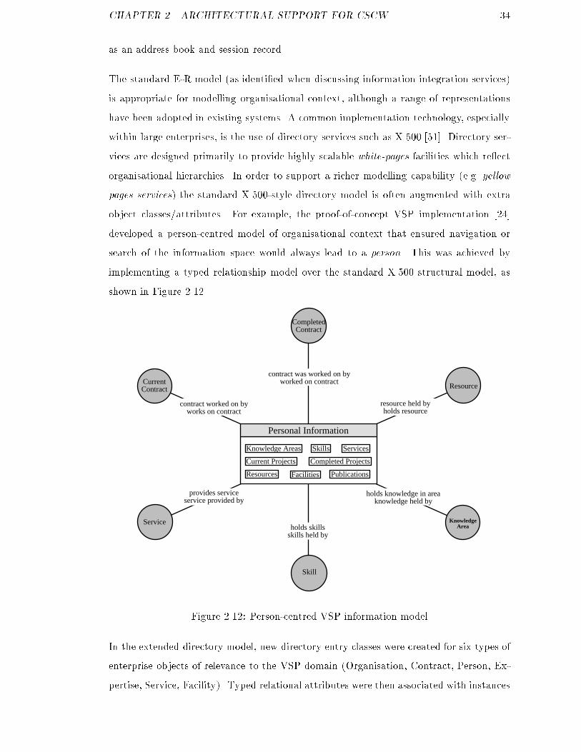
CHAPTER 2. ARCHITECTURAL SUPPORT FOR CSCW 33integration and presentation services which create a consistent view of the informationspace.There are a number of feasible approaches to integration of multiple databases [65] atthe syntactic level. The most commonly practised technique is to map underlying datamodels (and thereby, instances) into a global conceptual schema [10]. This approachis taken in the VSP and related VWS implementations through the use of databasewrappers, interactive translation tools and bulkload adapters [25]. Alternative techniques(e.g. federation and semantic uni�cation [95, pp. 1{14]) rely on higher level services toprovide more sophisticated integration services.In this work there is a clear need to support information integration services, but theresearch requirements can largely be met by existing tools. The assumption made withrespect to information integration services (at a system architectural level) is that, whilsta range of heterogeneous database systems must be supported (e.g. relational data inSQL tables, organisational directory information in X.500), all such data structures canconceptually be characterised using a conventional entity-relationship (E-R) model [19].Since the relational model of data is theoretically rigorous, this is a reasonable assumptionto make. The practical implication for this work is an emphasis on achieving integrationusing a standard approach, rather than aiming to provide a computationally e�cientimplementation. It should, however, be possible to create an e�cient implementation ofthe architecture within a production-quality system.Organisational context provisionWork is generally situated within an organisational context. In a physically-colocatedwork scenario this context is implicit in the familiar o�ce environment, but in a com-puter supported geographically-distributed collaboration scenario this context must berepresented explicitly within the system [6]. A model of organisational context within aCSCW environment describes the objects and relationships that are of interest in a par-ticular enterprise, e.g. people, projects, roles management structures, locations etc. [45].Once the enterprise has been characterised according to this model, CSCW applicationscan be built that operate (and interoperate) within it. For example, within the VWS en-vironment proposed in [48], multimedia conferencing clients use a shared directory service
CHAPTER 2. ARCHITECTURAL SUPPORT FOR CSCW 34as an address book and session record.The standard E-R model (as identi�ed when discussing information integration services)is appropriate for modelling organisational context, although a range of representationshave been adopted in existing systems. A common implementation technology, especiallywithin large enterprises, is the use of directory services such as X.500 [51]. Directory ser-vices are designed primarily to provide highly scalable white-pages facilities which re ectorganisational hierarchies. In order to support a richer modelling capability (e.g. yellowpages services) the standard X.500-style directory model is often augmented with extraobject classes/attributes. For example, the proof-of-concept VSP implementation [24]developed a person-centred model of organisational context that ensured navigation orsearch of the information space would always lead to a person. This was achieved byimplementing a typed relationship model over the standard X.500 structural model, asshown in Figure 2.12.Skill
Service
Resource
KnowledgeArea
Personal Information
holds knowledge in areaknowledge held by
holds skillsskills held by
provides serviceservice provided by
contract worked on byworks on contract
contract was worked on byworked on contract
resource held byholds resource
CurrentContract
Current Projects Completed Projects
Knowledge Areas Skills Services
Resources Facilities
CompletedContract
Publications
Figure 2.12: Person-centred VSP information modelIn the extended directory model, new directory entry classes were created for six types ofenterprise objects of relevance to the VSP domain (Organisation, Contract, Person, Ex-pertise, Service, Facility). Typed relational attributes were then associated with instances

CHAPTER 2. ARCHITECTURAL SUPPORT FOR CSCW 35of these classes e.g. Person works for Organisation. This model enabled intuitive infor-mation services to be constructed, enabling e�cient resolution of queries such as \�ndall information about service X; which companies provide X; who within these companiesshould I speak to about X" etc.Directories (especially when extended to enable richer descriptive capability) provide ahighly appropriate medium for representing organisational information within integratedCSCW environments [98]. Research systems such as the Virtual Science Park [24] andNexor's Enterprise Information System [45] were amongst the �rst projects to utiliseextended directory services within CSCW environments. Since the initial phases of theseprojects, several major network computing vendors have embraced directory technology(cf. Netscape, Novell, Microsoft). This is fuelling increased organisational adoption ofdirectory services and, signi�cantly for this research, Internet-based directories to supportinter-enterprise collaboration.Another relevant perspective on organisational context provision is that of researchersworking on executable enterprise models. For example, the Toronto Virtual Enterprise(ToVE) project [8, 9] developed a set of organisation ontologies enabling a degree ofautomated common sense reasoning to be applied to an enterprise model. The ADEPTproject, as introduced in Chapter 1, de�nes a business process ontology which could beviewed as focused subset of an organisational context model. The CIMOSA3 framework[113] enables derivation of executable engineering enterprise models that can directly driveCIM processes. The AIAI Enterprise project [112] developed an ontology-base enterprisemodelling toolkit enabling e.g. business process simulation and predictive reasoning.Value-added information servicesThis broad class of services operates above syntactic information integration services asdescribed previously. The goal of services at this layer is to provide (or assist in the)semantic interpretation of information sources mapped into the information space at thesyntactic level. Within the VWS framework such services are provided by a mediatorcomponent based upon Wiederhold's I3 architecture. In [117], Wiederhold provides thefollowing de�nition of mediation:3Open Systems Architecture for Computer Integrated Manufacturing (CIM).
CHAPTER 2. ARCHITECTURAL SUPPORT FOR CSCW 36\amediator is a software module that exploits domain knowledge about certainsets or subsets of data to create information for a higher level of applications."There are many conceivable instances of such services e.g. information gathering, �lter-ing, pro�ling, ranking, abstraction and reporting. For example, the Carnot project atMCC4 [47] developed an agent-based architecture for semantic integration of heteroge-neous information sources. This research was extended in the InfoSleuth project [119]which adapted the Carnot architecture to operate in dynamic information environmentswith no centralised control, such as the World Wide Web. The KRAFT Project5 [39],within which BT Laboratories are a partner, applies constraint satisfaction techniques tomediation of heterogeneous information sources such as product speci�cations.The above examples make use of AI techniques to encode domain knowledge and provideinterpretive mediation services. This is not a pre-requisite for mediation services how-ever. Within the VWS architectural framework, mediation services are provided throughdetailed domain classi�cation schemes through which information is characterised. Forexample, within the VWS which supports the NEST Project,6 users searching for partic-ular services may only have a broad idea of relevant research areas. The use of detailedresearch classi�cations enables users to quickly narrow down their potential search space.Within NEST, the domain classi�cation scheme is specialised for description of researchinformation, but the general approach is widely applicable in di�erent communities andproblem domains [29].The What's New and Relevant (WNAR) service is a further example of a value-addedinformation service [25]. Here, VWS users can build up a personal pro�le describing sub-jects and events in which they are interested in (e.g. \notify me when project informationis updated."). The service has been implemented within the ADVISER project to providea personalised noti�cation service within the domain of EU RTD programmes [86].4Microelectronics and Computer Technology Corporation.5Knowledge Re-use and Fusion/Transformation6Network for Exploitation of Science and Technology
CHAPTER 2. ARCHITECTURAL SUPPORT FOR CSCW 372.3.4 User interface servicesWithin an integrated CSCW framework, user interface services are responsible for sup-porting and structuring user interaction with application services. The primary deliverymedium for Virtual Working Systems is the Internet, and the World Wide Web in par-ticular. User interfaces for Virtual Working Systems are therefore primarily constructedusing the Hypertext Markup Language (HTML). The Web interfaces are built dynami-cally using compiled and scripted gateway programs operating via the Common GatewayInterface (CGI) [42]. These programs typically access information services and then gen-erate HTML to present results to the user via the Web browser interface. For example,a personal o�ce within the VSP (e.g. Figure 1.4 on page 7) is generated by retrieving adatabase object from an organisational directory and then populating a HTML templatewith this information. In taking a broader view of user interface provision within a CSCWarchitecture, there are three distinct but related requirements to consider;Service synthesis at the user interface: to draw together access to application ser-vices via a user interface with a consistent look-and-feel,Abstraction of presentation services: to support as wide a range of Internet browsersand support software as possible,User interface adaptivity: to create user interfaces that more closely re ect the re-quirements of individual users or classes of users.2.3.4.1 Service synthesis at the user interfaceMany existing Web{database connectivity engines provide good support for generation ofstandard user interfaces for navigation and search of relational databases e.g. MicrosoftActive Server Pages and Allaire Cold Fusion products. Such products typically rely uponthe creation of HTML templates into which chunks of executable script are embeddedcf. [62]. Templates may be created manually or, in more sophisticated development tools,through a visual interface. At runtime, when a particular page representing a databasequery is requested through the Web server, the embedded script is executed and the resultset merged into the HTML template. The populated HTML page is then forwardedback to the client browser for rendering. Template-based approaches to Web interface
CHAPTER 2. ARCHITECTURAL SUPPORT FOR CSCW 38generation for information services have proved to be appropriate in many applicationdomains. It is, however, di�cult to integrate other types of service (e.g. coordination orcollaboration services) through this interface generation technique in existing commercialsystems.2.3.4.2 User interface adaptivityCooperative working scenarios often involve people with di�ering perspectives on the col-laboration. The perspective they hold upon the collaborative scenario might be de�nedor in uenced by their role, responsibilities, expertise or personal preferences. Di�eringperspectives are often re ected in di�ering user requirements in interaction with the coop-erative system. For example, a work ow user in an administrative role would be primarilyconcerned with their own worklist, whereas a managerial user might require an overviewof the progress being made by all subordinate sta�; an expert VWS user may prefer a terseinformational interface whereas a neophyte may prefer a more intuitive interface. Thus,there is a basic requirement for the CSCW environment to adapt it's user interface to meetthe heterogeneous requirements of the user community. In [104], Schneider-Hufschmidtet al provide an informal rationale for adaptive user interfaces, noting four general casesin which adaptive interface behaviour can be bene�cial;1. a system is used by users with di�erent requirements,2. a system is used by a user with changing requirements,3. a user works in a changing environment,4. a user works in di�erent system environments.Most CSCW scenarios exhibit at least one of these properties, hence it is useful to incor-porate some user interface adaptivity features within a general CSCW architetcure. Thiswork is directed towards an investigation of support for CSCW in internet environments,hence focusing upon Web user interfaces.

CHAPTER 2. ARCHITECTURAL SUPPORT FOR CSCW 39Within internet environments, there are two basic classes of interaction supported withinmajor browsers;� 2D interaction through HTML Web pages� 3D interaction through VRML worldsMost existing Web information systems provide support for a single basic interactionalstyle. That is, a uniform interface is speci�ed for all system users. One barrier to ex-ible generation of Web user interfaces is the deep linkage of content and presentationalconstructs in HTML. This problem is well-known however, and emerging Web standardssuch as XML [50] and cascading style sheets [114] are moving towards a solution.The pace of development of Internet technologies is so fast that it is di�cult to decidewhen to upgrade Virtual Working Systems to include the latest features. A broad goalin this work is to assist in this dilemma by enabling new interface generation features tobe embraced whilst still retaining regressive compatibility with existing techniques.This problem is particularly apparent when considering 3D Internet interaction [26]. TheVirtual Reality Modeling Language (VRML) [94] and associated interface generationand browser software provides scope for multi-user Internet interaction through phys-ical metaphors. As computing and network performance increase, 3D navigation andinteraction will undoubtedly become commonplace within Internet computing environ-ments. Existing research projects have demonstrated the bene�ts of 3D interaction insupporting exploration of large-scale information spaces e.g. cone trees [66], 3D databasenavigation in Virgilio [20], visualisation of organisational information in VR-Vibe [17].In addition, physical metaphors (e.g. the rooms metaphor) can be used to create intu-itive collaborative working environments (CVEs) e.g. cooperative working within Virtuosi[101] and DIVE [12]. Virtual Working Systems possess characteristics that suggest a 3Dinteractional style may be bene�cial i.e. the basic requirement for distributed system sup-port for interpersonal interaction within an organisational context and a large corpus ofdomain information. For example, within the Virtual Science Park project it has beenappropriate to adopt a physical metaphor in order to provide an intuitive working envi-ronment for users (e.g. users log on through the reception area and then move into theirhome tenancy or the information services building). However, the role of 3D delivery
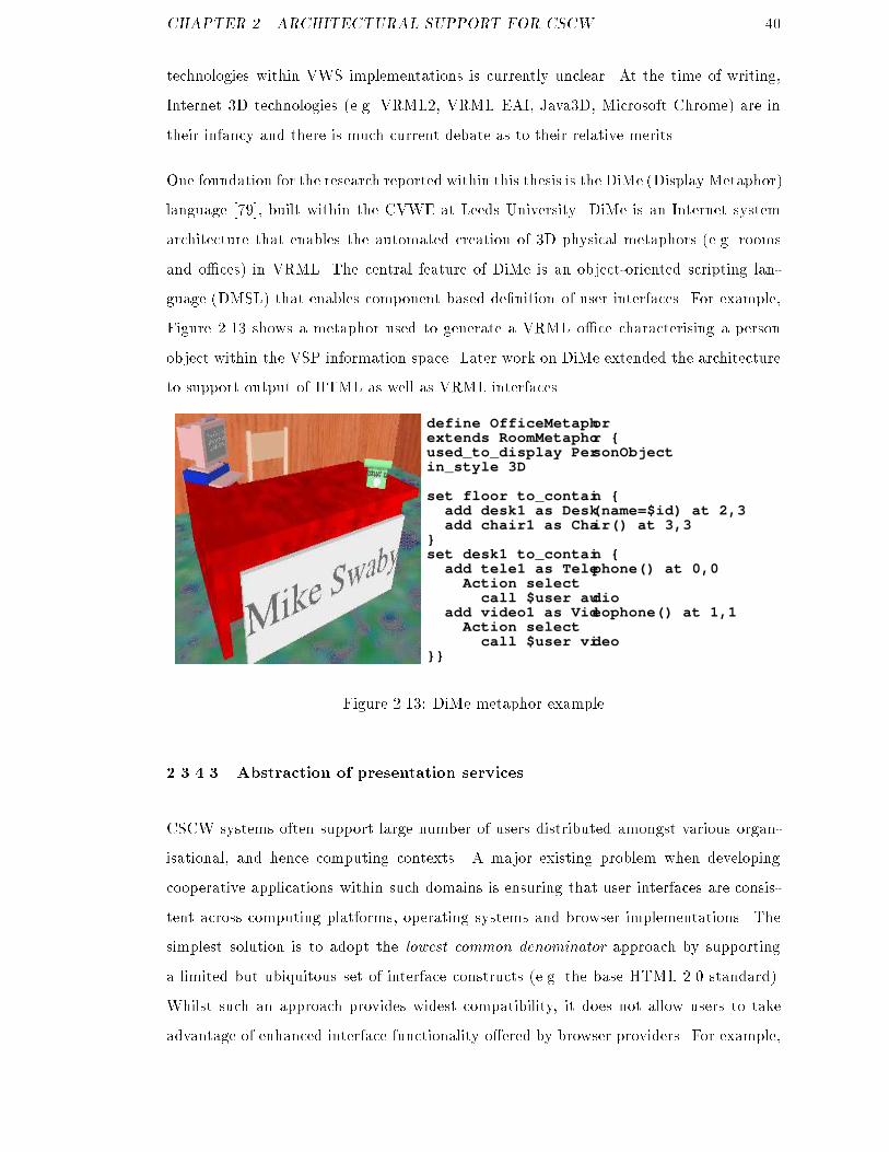
CHAPTER 2. ARCHITECTURAL SUPPORT FOR CSCW 40technologies within VWS implementations is currently unclear. At the time of writing,Internet 3D technologies (e.g. VRML2, VRML EAI, Java3D, Microsoft Chrome) are intheir infancy and there is much current debate as to their relative merits .One foundation for the research reported within this thesis is the DiMe (Display Metaphor)language [79], built within the CVWE at Leeds University. DiMe is an Internet systemarchitecture that enables the automated creation of 3D physical metaphors (e.g. roomsand o�ces) in VRML. The central feature of DiMe is an object-oriented scripting lan-guage (DMSL) that enables component based de�nition of user interfaces. For example,Figure 2.13 shows a metaphor used to generate a VRML o�ce characterising a personobject within the VSP information space. Later work on DiMe extended the architectureto support output of HTML as well as VRML interfaces.define OfficeMetaphorextends RoomMetaphor {used_to_display PersonObjectin_style 3D
set floor to_contain { add desk1 as Desk(name=$id) at 2,3 add chair1 as Chair() at 3,3 }set desk1 to_contain { add tele1 as Telephone() at 0,0 Action select call $user audio add video1 as Videophone() at 1,1 Action select call $user video}}Figure 2.13: DiMe metaphor example2.3.4.3 Abstraction of presentation servicesCSCW systems often support large number of users distributed amongst various organ-isational, and hence computing contexts. A major existing problem when developingcooperative applications within such domains is ensuring that user interfaces are consis-tent across computing platforms, operating systems and browser implementations. Thesimplest solution is to adopt the lowest common denominator approach by supportinga limited but ubiquitous set of interface constructs (e.g. the base HTML 2.0 standard).Whilst such an approach provides widest compatibility, it does not allow users to takeadvantage of enhanced interface functionality o�ered by browser providers. For example,

CHAPTER 2. ARCHITECTURAL SUPPORT FOR CSCW 41the two most popular Internet browsers (Microsoft Internet Explorer and Netscape Com-municator) both support proprietary tag sets that augment standard HTML as de�nedin the W3C HTML 4.0 speci�cation [100]. In addition, there is an increasing emergenceof client-side scripting languages [99] that provide support for interactivity within Webpages (e.g. JavaScript, JScript, VBScript, etc.) Again, there are many inconsistenciesin scripting implementations within di�erent browsers and across platforms. To allevi-ate these interface inconsistency problems, there is an increasing interest within the Websystems community in abstract interface generation techniques (as shown conceptuallyin Figure 2.14). This approach uses a neutral description language to generate Web in-terfaces tailored to particular platforms or browsers. The approach is useful within aninternet-based CSCW system in supporting as wide a range of user platforms as possible.User Interface
GeneratorMicrosoft Extensions
Vanilla HTML 3.2
Vanilla HTML 4.0
Netscape Extensions
Abstract UI Model
etc.Figure 2.14: Abstraction of presentation services2.3.5 Infrastructure ServicesCSCW applications attempt to overcome several types of distribution e.g. geographical,organisational and/or temporal. Within an integrated CSCW environment there is there-fore a clear requirement for basic support services to provide an infrastructure withinwhich these distributed applications can operate e�ectively. Object-oriented distributedsystems architectures such as ODP [23], ANSA [3] and CORBA [88] can provide manybasic services from which to construct CSCW applications e.g. remote procedure invo-cation, distributed database access, synchronisation and security. Although there canbe potential problems in utilising unmodi�ed distributed object architectures to create
CHAPTER 2. ARCHITECTURAL SUPPORT FOR CSCW 42CSCW systems (such as unwanted transparency [14]), they can provide a appropriatefoundation upon which which to construct integrated systems. Services requiring integra-tion may be purpose built (e.g. VWS services) or exist as legacy systems (e.g. work owmanagers). Distributed object services can enable integration through wrapping existingapplications to make them accessible to other objects within the collaboration environ-ment. A further advantage of a distributed object approach is that several generic (andhence reusable) services are usually provided, cf. support for object relationships, secu-rity, event management and database access in CORBA for example [87]. Utilisationof these common object services reduces developer e�ort and promotes modularity andcomponent re-use, which are major objectives in this research. Existing research projectshave produced promising results in applying distributed object technology in deliveringinternet-based systems. For example, CorbaWeb [75] enables transparent access to dis-tributed object applications through a standard Web browser interface. Web� [1] utilisesa similar template-based approach to provide integration services within CERCs Informa-tion Sharing System project.7 ORBWork [22] provides a distributed and scalable work owenactment environment based upon Web infrastructure.2.4 SummaryThrough a survey of a number of existing CSCW frameworks, this chapter has identi�edseveral core services that are required within a general CSCW architecture. Relevantrelated research and commercial development e�orts have then been described withinthese service classes. The objective in this study is to identify structured mechanismsthrough which individual services may be brought together within a CSCW architecture.A number of conclusions may be drawn from the investigation, which serve to guidedevelopment of the architecture proposed within this thesis;Coordination services provide support for managing the interdependencies betweenresources contributing towards a pre-de�ned or emergent common goal. Integration ofcoordination services within a CSCW architecture requires an external control interface.The work ow management coalition's reference architecure (WFMC-RA) was describedas an example of a coordination service which could feasibly be integrated within a general7Concurrent Engineering Research Center, West Virginia University

CHAPTER 2. ARCHITECTURAL SUPPORT FOR CSCW 43CSCW architecture.Collaboration services enable inter-personal interaction between members of a coop-erating group. Integration of such tools within a CSCW architecture is largely dependentupon the extent to which they support external control via a programming interface.Information management services integrate domain information sources into an in-formation space appropriate to the tasks undertaken within the cooperative working sce-nario. A number of information service layers were identi�ed, within which related workwas positioned. The requirement within this work is to provide basic mechanisms forinformation access, upon which services implemented within these layers might be imple-mented.User interface services enable system users to interact with the CSCW environmentin an appropriate manner. Three main roles for a user interface service within a CSCWarchitecture were identi�ed; service synthesis at the user interface, abstraction of presen-tation services and user interface adaptivity. The DiMe architecture, developed withinthe CVWE, was introduced as a exible Web user interface generator which can be usedto deliver user interfaces within a CSCW architecture.Infrastructure services provide middleware components to integrate CSCW servicestogether within a systems environment. Distributed object architectures such as CORBAwere identi�ed as useful in enabling interoperability between CSCW service implementa-tions.

Chapter 3Model-based CSCW architectureChapter 1 introduced the research problem as a general requirement for structured devel-opment techniques for integrated internet CSCW systems, that promote service compo-nent reuse and enable rapid iterative development. Chapter 2 then characterised existingCSCW services and surveyed related research and development e�orts within �ve broadclasses (coordination, collaboration, information management, user interface and infras-tructure). This survey identi�ed mechanisms through which services might be broughttogether into integrated applications by a CSCW architecture. This chapter describesthe detailed design of ParaDiMe, an architecture for integrated internet CSCW systemswhich supports a model-based approach to iterative systems development. The researchhypothesis is that the proposed model-based approach can solve the research problemsidenti�ed in Chapter 1.The basic conceptual approach taken within this work is to raise the level of abstractionat which cooperative applications are built and subsequently modi�ed over time. The re-search problem is fundamentally a component integration and change management prob-lem, current solutions to which are generally applied at the lower levels of layered systemsarchitectures. For example, CORBA supports integration of heterogeneous client-servercomponents through mutual commitment to a common remote procedure call (RPC)mechanism. However, application end-users and the requirements analysts who representthem are largely unconcerned with such levels of architectural detail. When buildingprototype system implementations or designing systems according to a Rapid Applica-tion Development (RAD) method, there are two basic considerations that guide initial44
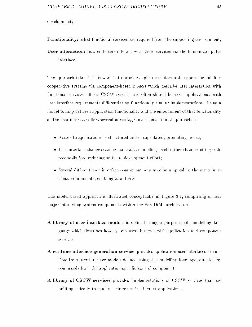
CHAPTER 3. MODEL-BASED CSCW ARCHITECTURE 45development;Functionality: what functional services are required from the supporting environment,User interaction: how end-users interact with these services via the human-computerinterface.The approach taken in this work is to provide explicit architectural support for buildingcooperative systems via component-based models which describe user interaction withfunctional services. Basic CSCW services are often shared between applications, withuser interface requirements di�erentiating functionally similar implementations. Using amodel to map between application functionality and the embodiment of that functionalityat the user interface o�ers several advantages over conventional approaches;� Access to applications is structured and encapsulated, promoting re-use;� User interface changes can be made at a modelling level, rather than requiring coderecompilation, reducing software development e�ort;� Several di�erent user interface component sets may be mapped to the same func-tional components, enabling adaptivity;The model-based approach is illustrated conceptually in Figure 3.1, comprising of fourmajor interacting system components within the ParaDiMe architecture;A library of user interface models is de�ned using a purpose-built modelling lan-guage which describes how system users interact with application and componentservices.A runtime interface generation service provides application user interfaces at run-time from user interface models de�ned using the modelling language, directed bycommands from the application-speci�c control component.A library of CSCW services provides implementations of CSCW services that arebuilt speci�cally to enable their re-use in di�erent applications.

CHAPTER 3. MODEL-BASED CSCW ARCHITECTURE 46User interface component model
User interfacegenerator
Cooperativeapplication
Web userinterfaces
Re-usable CSCWservices
embedcommandsto interactwith
integrate into
generates
defines operation of
controls Application layer
Presentation layerspecifies userinteraction with
Figure 3.1: Conceptual view of the model-based approachApplication components implement application speci�c functionality and integrateaccess to general CSCW services where required.The ParaDiMe architecture was developed to enable assessment of the proposed model-based systems development approach by supporting exploration of case study CSCWapplications. The central architectural component within ParaDiMe is the DiMe userinterface generation toolkit [79], created within the CVWE by David Morris and GyuriLajos who acted as technical supervisors in this research. ParaDiMe extends the capabil-ities of DiMe to facilitate rapid iterative development of integrated internet-based CSCWsystems [111].The role of the �rst generation of DiMe architecture was to automate construction ofVRML and HTML user interfaces to organisational directory servers. A batch modeDiMe implementation was built in order to generate VRML models of the directory usinga 3D rooms metaphor. In addition, an interactive Web gateway implementation wasconstructed which enabled HTML interfaces to be created dynamically as users navigate
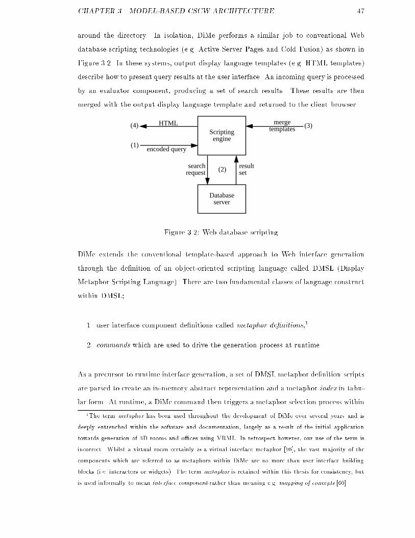
CHAPTER 3. MODEL-BASED CSCW ARCHITECTURE 47around the directory. In isolation, DiMe performs a similar job to conventional Webdatabase scripting technologies (e.g. Active Server Pages and Cold Fusion) as shown inFigure 3.2. In these systems, output display language templates (e.g. HTML templates)describe how to present query results at the user interface. An incoming query is processedby an evaluator component, producing a set of search results. These results are thenmerged with the output display language template and returned to the client browser.Database
server
encoded query
Scriptingengine
HTML
searchrequest
resultset
mergetemplates
(2)
(4)
(1)
(3)
Figure 3.2: Web database scriptingDiMe extends the conventional template-based approach to Web interface generationthrough the de�nition of an object-oriented scripting language called DMSL (DisplayMetaphor Scripting Language). There are two fundamental classes of language constructwithin DMSL;1. user interface component de�nitions called metaphor de�nitions,12. commands which are used to drive the generation process at runtime.As a precursor to runtime interface generation, a set of DMSL metaphor de�nition scriptsare parsed to create an in-memory abstract representation and a metaphor index in tabu-lar form. At runtime, a DiMe command then triggers a metaphor selection process within1The term metaphor has been used throughout the development of DiMe over several years and isdeeply entrenched within the software and documentation, largely as a result of the initial applicationtowards generation of 3D rooms and o�ces using VRML. In retrospect however, our use of the term isincorrect. Whilst a virtual room certainly is a virtual interface metaphor [96], the vast majority of thecomponents which are referred to as metaphors within DiMe are no more than user interface buildingblocks (i.e. interactors or widgets). The term metaphor is retained within this thesis for consistency, butis used informally to mean interface component rather than meaning e.g. mapping of concepts [60].

CHAPTER 3. MODEL-BASED CSCW ARCHITECTURE 48DiMe. During metaphor selection, the index is used to identify and instantiate appropri-ate metaphors which form a tree representation. This tree is then passed to the DiMeoutput generators (for HTML/VRML etc.) which traverse the internal representationand emit appropriate target language constructs. This output is then returned to therequesting client through the Web server CGI mechanism. This template-based user in-terface generation mechanism forms the core of the ParaDiMe architecture through whichthe model-based approach to construction of integrated internet information systems isexplored within this research. DMSL is used as the modelling-language which speci�esuser interaction with CSCW applications and the services they integrate.The chapter begins by describing the DiMe object model (Section 3.1) and DMSLmetaphorde�nition constructs (Section 3.3). An understanding of these fundamental DiMe elementsis essential in introducing the ParaDiMe architecture which is built using them. Althoughthe author contributed towards the development of these components, it should be clearlynoted that they were invented by David Morris and Gyuri Lajos and hence, do not formpart of the contribution of this thesis. However, it is necessary to describe them herebecause they are critical to the work and no suitable (published or internal) materialexists to which the reader could otherwise be referred.Building upon these existing DiMe components, Section 3.4 introduces the ParaDiMeruntime user interface generation service. This extends DiMe via a distributed objectarchitecture which enables ParaDiMe to support integrated access to reusable CSCWservices within applications. Within ParaDiMe, several basic mechanisms are providedwhich may be used to provide integrated access to applications and component services.An information management service is provided through which access to heterogeneousdomain information sources is supported (Section3.5). A forms-processing subsystem en-ables user interaction with applications via HTML forms (Section 3.6). A remote methodinvocation service is provided, through which access to external services (e.g. work owenactment services) is supported (Section 3.7). Finally, a collaborative tools subsystemis de�ned, which supports execution and subsequent session control of appropriate syn-chronous groupware tools (Section 3.8). Following discussion of these architectural com-ponents, from which integrated internet CSCW applications may be constructed, Section3.9 describes a simple RAD-type methodology which may be used to guide developmentof systems using ParaDiMe.

CHAPTER 3. MODEL-BASED CSCW ARCHITECTURE 493.1 The DiMe object modelMetaphor de�nition constructs in DMSL are directly re ected by internal operations onmetaphor abstract data types (ADTs) within DiMe. It is therefore bene�cial to discussthis internal representation before covering DMSL in detail. As mentioned earlier, DiMecurrently supports integrated generation of HTML and VRML user interfaces. The �rstimplementation of DiMe solely supported 3D interface generation however, built uponthe SGI Inventor 3D graphics libraries [115].Inventor (in common with several other similar products) provides a scene-graph API forconstruction of 3D models in which hierarchies of objects (called nodes) de�ne parent{childrelationships between objects. In simpli�ed terms, nodes may represent particular objectsin the scene (e.g. a cube or sphere), collect other objects together (e.g a grouping node)or apply some other operation on child nodes (e.g. colour, texture, or transformation).Container nodes implement methods which manage the set of children attached to theme.g. add child, remove child, etc. Rendering a scene to screen or saving a descriptionas VRML requires traversal of the scene graph (de�ned by a root grouping node) byvisiting subordinate nodes in a de�ned order. The object-oriented scene graph approach to3D graphics programming is simple yet exible. DiMe adopts this fundamental approachbut with two important extensions;� augmenting the 3D scene graph model with a 2D HTML document object model(DOM),� an abstract layer of built-in objects with enhanced child management capabilities.Hypertext Markup Language (HTML) uses tags to associate semantics with textual in-formation. For example, <title>My Page</title> de�nes the title of a document to bethe string \My Page." Upon parsing of this tag, a Web browser would typically name thewindow within which it is running accordingly. Tags such as head and body de�ne thestructure of the document, leading to a tree-based document representation very similarto scene-graphs in 3D graphics programming. A HTML document library was createdusing this approach and integrated with the 3D scene generation library within DiMe, asshown in Figure 3.3.22The World Wide Web Consortium have subsequently pursued an analogous approach through their
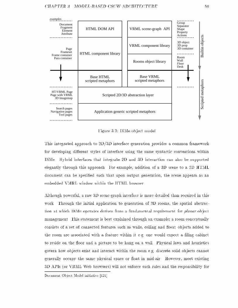
CHAPTER 3. MODEL-BASED CSCW ARCHITECTURE 50HTML DOM API VRML scene-graph API
HTML component library
VRML component library
Base HTMLscripted metaphors
Base VRMLscripted metaphors
Scripted 2D/3D abstraction layer
Application generic scripted metaphors
Rooms object library
examples
DocumentFragmentElement
Attribute
PageFrameset
Frame containerPara container
GroupSeparatorShapePropertyActions
3D object3D prop3D container
RoomWallFloorDesk
HT/VRML PagePage with VRML
3D Imagemap
Search pagesNavigation pages
Tool pages
Bui
ltin
obje
cts
Scri
pted
met
apho
rs
Figure 3.3: DiMe object modelThis integrated approach to 2D/3D interface generation provides a common frameworkfor developing di�erent styles of interface using the same syntactic conventions withinDiMe. Hybrid interfaces that integrate 2D and 3D interaction can also be supportedelegantly through this approach. For example, addition of a 3D scene to a 2D HTMLdocument can be speci�ed such that upon output generation, the scene appears as anembedded VMRL window within the HTML browser.Although powerful, a raw 3D scene-graph interface is more detailed than required in thiswork. Through the initial application to generation of 3D rooms, the spatial abstrac-tion at which DiMe operates derives from a fundamental requirement for planar objectmanagement. This statement is best explained through an example; a room conceptuallyconsists of a set of connected features such as walls, ceiling and oor; objects added tothe room are associated with a feature within it e.g. one would expect a �ling cabinetto reside on the oor and a picture to be hung on a wall. Physical laws and heuristicsgovern how objects exist and interact within the room e.g. discrete solid objects cannotgenerally occupy the same physical space or oat in mid-air. However, most existing3D APIs (or VRML Web browsers) will not enforce such rules and the responsibility forDocument Object Model initiative [121].
CHAPTER 3. MODEL-BASED CSCW ARCHITECTURE 51creating physically feasible scenes rests with the developer.Supporting physically realistic object management within 3D environments is a very hardproblem, but because DiMe is specialised for room scenes structured within a set of 2Dplanes, some useful support can be provided at low cost. The approach taken withinDiMe is to provide a set of built-in 3D objects based on sets of 2D layout planes whichembody simple physical and common sense heuristic knowledge about how child objectsshould be arranged. For example, a request to add three pictures to a built-in wall objectwill result in the pictures being hung evenly across the width of the wall at an appropriateheight. Adding a telephone to a desk will place the telephone on top of the desk facingthe front. A set of several appropriate built-in objects is de�ned within DiMe (e.g. rooms,walls, oors, desktops etc.) enabling realistic room scenes to be created at an appropriateabstract level within DMSL.3 Basic support for HTML generation is also provided usingbuilt-in objects, although the API is much simpler as there is no requirement for objectlayout other than that implicit in HTML tag ordering.3.2 Display Metaphor Scripting Language (DMSL)Display Metaphor Scripting Language (DMSL) is a proprietary object-oriented scriptinglanguage which forms the core of the DiMe architecture. DMSL externalises the DiMeobject model as described above via an intuitive high-level programming language. Withinthe current DiMe architecture, support for DMSL is implemented using the PCCTScompiler construction toolkit [91]. At the abstract level however, DMSL is a frame-based language [77] and it should therefore be noted that many other implementationsare feasible.43Abstract spatial layout managers (e.g. supporting object grids, lattices and rings etc) have beenspeci�ed within the DiMe architectured but have not been implemented successfully to date.4For example, early experimental work packages within this PhD project investigated rule-based imple-mentations of the DiMe architecture using Common Lisp [108] and CLIPS [34]. The investigation foundsuch approaches to be highly appropriate for knowledge representation and reasoning within DiMe, butinteractive performance was extremely inferior to the custom-built DMSL implementation.

CHAPTER 3. MODEL-BASED CSCW ARCHITECTURE 52The fundamental concept in DiMe and DMSL is the metaphor; A metaphor within DiMerepresents a user interface component at some level of abstraction in the DiMe objectmodel. The simplest metaphors act as wrappers for built-in objects in the (HTML andVRML) output generation APIs. Scripted metaphors then extend these base objectsto create interface components specialised for particular purposes. DMSL is used toincrementally construct a (potentially complex) user interface model for a cooperativesystem from re-usable building-block metaphor components. At the conceptual level, aDMSL metaphor is a frame consisting of four sets of slots;variable slots: maintain state through string, integer or oating point expressions,content slots: de�ne instances of component metaphorsconstructor slots map a metaphor to a built-in object in the DiMe object model,operator slots: specify actions, transformations and other operations to be applied tothe metaphor at generation.As a concrete example of how these slots characterise a user interface component, con-sider invocation of VWS videoconferencing services within a 3D room interaction style.A feasible interactional scenario is for the system user to navigate an organisational infor-mation space and locate the person they wish to contact, perhaps via a 3D representationof their o�ce. Upon entering the virtual o�ce, the system user establishes a videocon-ferencing session with the target user by clicking on a phone object positioned within thescene. This scenario implicitly embodies managed access to the application informationspace and structured invocation of a groupware tool. A DMSL metaphor can packageup an executable model of these requirements that can be re-used and specialised acrossapplications. So, a re-usable metaphor encapsulating the above properties might de�nethe following slot values;variable slots: videoconferencing address to dial, label to put on phone, user id of targetuser,content slots: in this example the phone is an atomic object and therefore has no com-ponent metaphors,constructor slots: the phone is an extension of a built-in prop object,
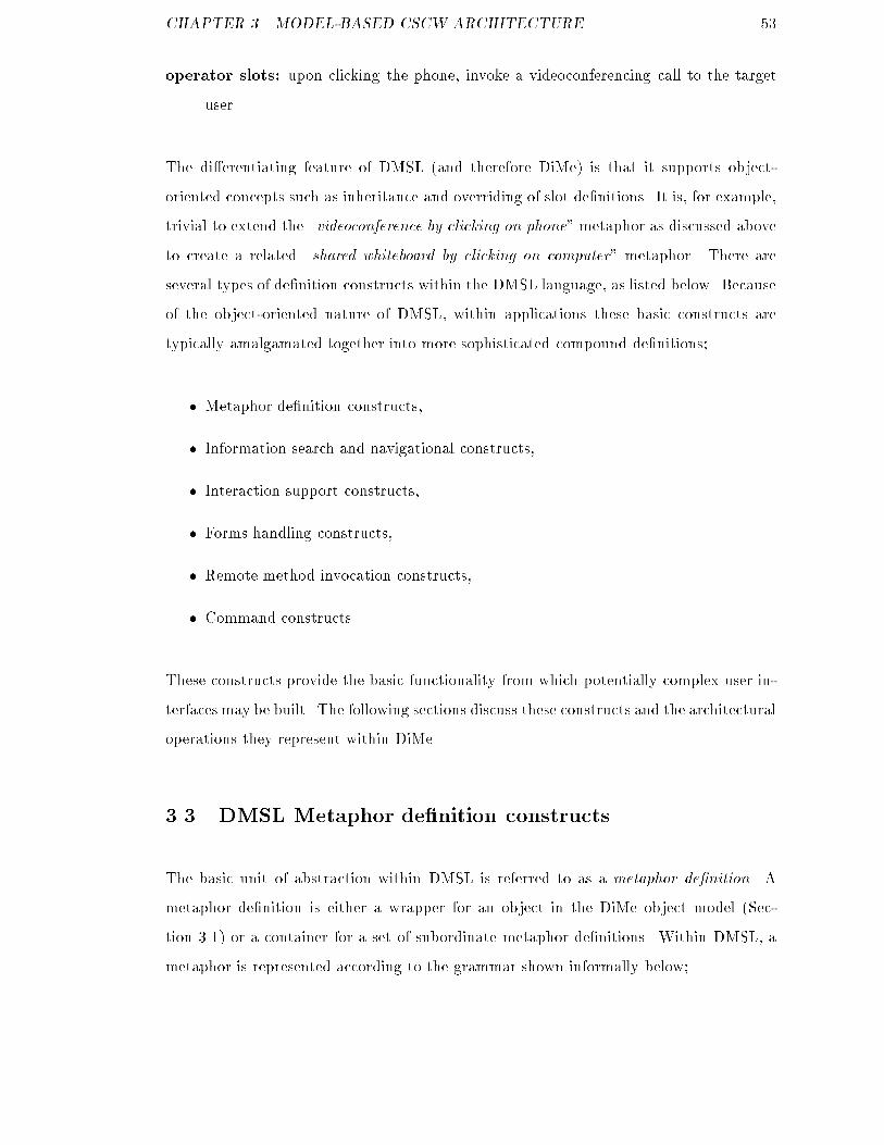
CHAPTER 3. MODEL-BASED CSCW ARCHITECTURE 53operator slots: upon clicking the phone, invoke a videoconferencing call to the targetuser.The di�erentiating feature of DMSL (and therefore DiMe) is that it supports object-oriented concepts such as inheritance and overriding of slot de�nitions. It is, for example,trivial to extend the \videoconference by clicking on phone" metaphor as discussed aboveto create a related \shared whiteboard by clicking on computer" metaphor. There areseveral types of de�nition constructs within the DMSL language, as listed below. Becauseof the object-oriented nature of DMSL, within applications these basic constructs aretypically amalgamated together into more sophisticated compound de�nitions;� Metaphor de�nition constructs,� Information search and navigational constructs,� Interaction support constructs,� Forms handling constructs,� Remote method invocation constructs,� Command constructs.These constructs provide the basic functionality from which potentially complex user in-terfaces may be built. The following sections discuss these constructs and the architecturaloperations they represent within DiMe.3.3 DMSL Metaphor de�nition constructsThe basic unit of abstraction within DMSL is referred to as a metaphor de�nition. Ametaphor de�nition is either a wrapper for an object in the DiMe object model (Sec-tion 3.1) or a container for a set of subordinate metaphor de�nitions. Within DMSL, ametaphor is represented according to the grammar shown informally below;
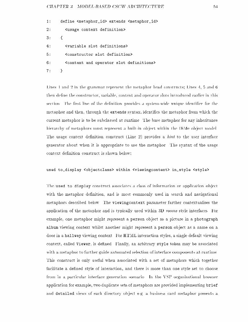
CHAPTER 3. MODEL-BASED CSCW ARCHITECTURE 541: define <metaphor_id> extends <metaphor_id>2: <usage context definition>3: {4: <variable slot definitions>5: <constructor slot definition>6: <content and operator slot definitions>7: }Lines 1 and 2 in the grammar represent the metaphor head constructs; Lines 4, 5 and 6then de�ne the constructor, variable, content and operator slots introduced earlier in thissection. The �rst line of the de�nition provides a system-wide unique identi�er for themetaphor and then, through the extends syntax, identi�es the metaphor from which thecurrent metaphor is to be subclassed at runtime. The base metaphor for any inheritancehierarchy of metaphors must represent a built-in object within the DiMe object model.The usage context de�nition construct (Line 2) provides a hint to the user interfacegenerator about when it is appropriate to use the metaphor. The syntax of the usagecontext de�nition construct is shown below;used to_display <objectclass> within <viewingcontext> in_style <style>The used to display construct associates a class of information or application objectwith the metaphor de�nition, and is most commonly used in search and navigationalmetaphors described below. The viewingcontext parameter further contextualises theapplication of the metaphor and is typically used within 3D rooms style interfaces. Forexample, one metaphor might represent a person object as a picture in a photographalbum viewing context whilst another might represent a person object as a name on adoor in a hallway viewing context. For HTML interaction styles, a single default viewingcontext, called Viewer, is de�ned. Finally, an arbitrary style token may be associatedwith a metaphor to further guide automated selection of interface components at runtime.This construct is only useful when associated with a set of metaphors which togetherfacilitate a de�ned style of interaction, and there is more than one style set to choosefrom in a particular interface generation scenario. In the VSP organisational browserapplication for example, two duplicate sets of metaphors are provided implementing briefand detailed views of each directory object e.g. a business card metaphor presents a

CHAPTER 3. MODEL-BASED CSCW ARCHITECTURE 55person object in a brief style; a curriculum vitae metaphor presents the same object ina detailed interaction style;define BusinessCard extends HTMLPageused to_display PersonObject within Viewer in_style Brief ...define CV extends HTMLPageused to_display PersonObject within Viewer in_style Detailed ...De�nition of metaphors tailored to speci�c object classes, viewing contexts and styles iscentral to runtime interface generation exibility within DiMe. The body of a metaphorde�nes values of four component slots as introduced earlier (variables, constructor, contentand operator slots). The variable slot supports basic de�nition of integer, oating pointand string variables, with identi�ers scoped to the local metaphor. Literal and simpleexpression values are supported. The variable de�nition grammar is shown below; theadd construct adds a new variable to the metaphor and assigns it an initial value, theset construct is used to alter the value of a de�ned variable, the (seldom used) removeconstruct removes an inherited variable from the current metaphor de�nition.add|set <id> = <expression>remove <id>Variables are a critically important feature of metaphor de�nitions, providing the samefunctionality (and advantages) as function parameters in conventional block structuredprocedural programming languages. Within DiMe, metaphor variables ful�ll two roles.Firstly, they can be used to specialise metaphors added at build-time to the content slot(covered later in this section). Secondly, they enable dynamic binding of variables asmetaphor parameters at runtime (covered in Section 3.4).The constructor slot within a metaphor can only be de�ned in base metaphors, andidenti�es which built-in object should be instantiated at runtime to generate the inter-face components represented in the metaphor. All metaphors must be associated witha constructor before interface generation, and once de�ned the constructor may not beoverridden. The use of the constructor de�nition is illustrated in the example shownbelow. This DMSL fragment, taken from the DiMe VSP demonstrator, de�nes a base
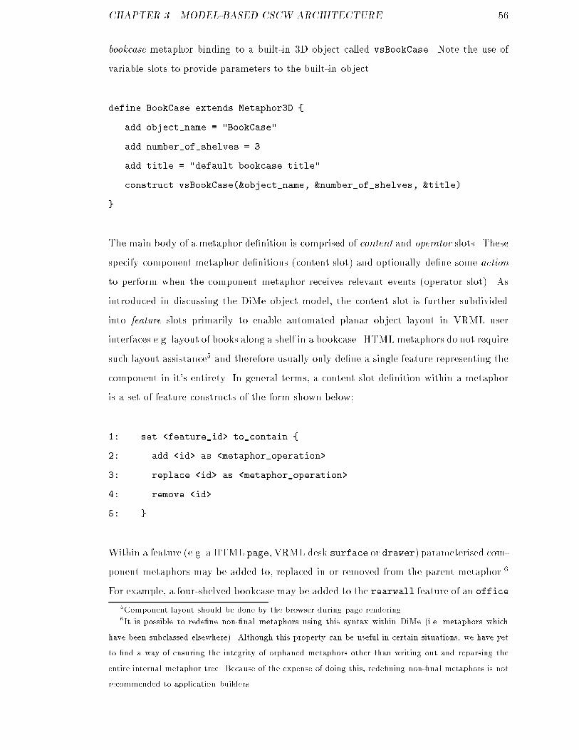
CHAPTER 3. MODEL-BASED CSCW ARCHITECTURE 56bookcase metaphor binding to a built-in 3D object called vsBookCase. Note the use ofvariable slots to provide parameters to the built-in object.define BookCase extends Metaphor3D {add object_name = "BookCase"add number_of_shelves = 3add title = "default bookcase title"construct vsBookCase(&object_name, &number_of_shelves, &title)}The main body of a metaphor de�nition is comprised of content and operator slots. Thesespecify component metaphor de�nitions (content slot) and optionally de�ne some actionto perform when the component metaphor receives relevant events (operator slot). Asintroduced in discussing the DiMe object model, the content slot is further subdividedinto feature slots primarily to enable automated planar object layout in VRML userinterfaces e.g. layout of books along a shelf in a bookcase. HTML metaphors do not requiresuch layout assistance5 and therefore usually only de�ne a single feature representing thecomponent in it's entirety. In general terms, a content slot de�nition within a metaphoris a set of feature constructs of the form shown below;1: set <feature_id> to_contain {2: add <id> as <metaphor_operation>3: replace <id> as <metaphor_operation>4: remove <id>5: }Within a feature (e.g. a HTML page, VRML desk surface or drawer) parameterised com-ponent metaphors may be added to, replaced in or removed from the parent metaphor.6For example, a four-shelved bookcase may be added to the rearwall feature of an office5Component layout should be done by the browser during page rendering.6It is possible to rede�ne non-�nal metaphors using this syntax within DiMe (i.e. metaphors whichhave been subclassed elsewhere). Although this property can be useful in certain situations, we have yetto �nd a way of ensuring the integrity of orphaned metaphors other than writing out and reparsing theentire internal metaphor tree. Because of the expense of doing this, rede�ning non-�nal metaphors is notrecommended to application builders.

CHAPTER 3. MODEL-BASED CSCW ARCHITECTURE 57metaphor using the following syntax (which also demonstrates variable overriding in con-tent metaphor de�nitions);1: set rearwall to_contain {2: add b1 as BookCase(number_of_shelves=4)3: }For each component de�ned within the content slot of a metaphor (e.g. as shown above)an operator slot de�nition may associate an action to be performed when a particularruntime event occurs that is of relevance to the component. This slot provides the basicmechanism through which all user interactivity is supported in DiMe. The operation ofthis mechanism will be discussed in detail later, but it is useful to introduce the basicapproach at this stage.Within standard HTML pages, the most common interactive operation is hyperlink selec-tion e.g. clicking a textual, image or imagemap link. A wider range of events are feasibleusing client-scripting or within VRML browsers e.g mouse-over, proximity sensing etc.Through the operator slot de�nition construct, the DiMe runtime architecture supportsthree types of interactive operation;1. generation of another metaphor,2. execution of an information space query,3. invocation of a remote application-layer method.Within the runtime architecture, interactive operational support is achieved by embed-ding DMSL commands within URLs7 that form part of the generated output language(e.g. HTML href or VRML WWWAnchor �elds). This mechanism is shown conceptually inFigure 3.1, and will be discussed in detail in the following sections. However, an informalappreciation for the operation of the construct can be gained with reference to a simpleexample.7Uniform Resource Locators.
CHAPTER 3. MODEL-BASED CSCW ARCHITECTURE 581: add link1 as HyperTextLink()2: Action select view Data3: in "Viewer"4: in_style "DetailedPage"5: label 'View ' + Data.name + ' in more detail.'The above DMSL fragment shows a content de�nition with an associated operator slotde�nition provided through the Action syntax. This example is part of a HTMLmetaphorused in navigating an information space. It generates a textual hyperlink which, whenselected, executes a DiMe command to view the current information object (denotedby the reserved Data keyword) in a more detailed style. Before describing support forinteractive operations within the ParaDiMe architecture, it is useful to describe DiMecommands and the operation of the runtime interface generator.3.4 Interactive operation of ParaDiMe3.4.1 DMSL commandsThe previous section introduced metaphor de�nition within DMSL. A set of appropriately-written DMSL metaphor scripts (utilising styles, viewing contexts, and object class ref-erences) provides a comprehensive and exible user interface model for a collaborativeapplication. DMSL is implementation-oriented however; that is, DMSL is designed to beexecuted as a scripting language by an interpreter or similar runtime processor ratherthan serving a purely representational role. Within ParaDiMe, which extends the DiMeoutput generation architecture, there is therefore a distinction between build-time whenmetaphor de�nitions are parsed to form an internal user interface model, and runtimewhen this model is used to guide interactive generation of HTML and VRML user inter-faces (Figure 3.4)At build-time, a set of DMSL metaphor de�nitions is parsed to form an internal repre-sentation of user interface components. Runtime interface generation is driven throughthe interpretation of a simple set of DMSL command constructs, guided by the internalinterface model. The command interpretation process formulates a tree of metaphor ob-
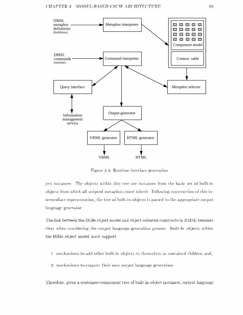
CHAPTER 3. MODEL-BASED CSCW ARCHITECTURE 59Metaphor interpreter
Command interpreter
Informationmanagement
service
Context table
Component model
Query interface Metaphor selector
Output generator
VRML generator HTML generator
DMSL metaphordefinitions
DMSLcommands
(buildtime)
(runtime)
VRML HTMLFigure 3.4: Runtime interface generationject instances. The objects within this tree are instances from the basic set of built-inobjects from which all scripted metaphors must inherit. Following construction of this in-termediate representation, the tree of built-in objects is passed to the appropriate outputlanguage generator.The link between the DiMe object model and object-oriented constructs in DMSL becomesclear when considering the output language generation process. Built-In objects withinthe DiMe object model must support1. mechanisms to add other built-in objects to themselves as contained children and,2. mechanisms to support their own output language generation.Therefore, given a container{component tree of built-in object instances, output language
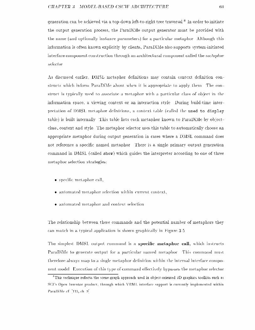
CHAPTER 3. MODEL-BASED CSCW ARCHITECTURE 60generation can be achieved via a top-down left-to-right tree traversal.8 In order to initiatethe output generation process, the ParaDiMe output generator must be provided withthe name (and optionally instance parameters) for a particular metaphor. Although thisinformation is often known explicitly by clients, ParaDiMe also supports system-initiatedinterface component construction through an architectural component called themetaphorselector.As discussed earlier, DMSL metaphor de�nitions may contain context de�nition con-structs which inform ParaDiMe about when it is appropriate to apply them. The con-struct is typically used to associate a metaphor with a particular class of object in theinformation space, a viewing context or an interaction style. During build-time inter-pretation of DMSL metaphor de�nitions, a context table (called the used to displaytable) is built internally. This table lists each metaphor known to ParaDiMe by object-class, context and style. The metaphor selector uses this table to automatically choose anappropriate metaphor during output generation in cases where a DMSL command doesnot reference a speci�c named metaphor. There is a single primary output generationcommand in DMSL (called show) which guides the interpreter according to one of threemetaphor selection strategies;� speci�c metaphor call,� automated metaphor selection within current context,� automated metaphor and context selectionThe relationship between these commands and the potential number of metaphors theycan match in a typical application is shown graphically in Figure 3.5.The simplest DMSL output command is a speci�c metaphor call, which instructsParaDiMe to generate output for a particular named metaphor. This command musttherefore always map to a single metaphor de�nition within the internal interface compo-nent model. Execution of this type of command e�ectively bypasses the metaphor selector8This technique re ects the scene-graph approach used in object-oriented 3D graphics toolkits such asSGI's Open Inventor product, through which VRML interface support is currently implemented withinParaDiMe cf. [115, ch. 9].
CHAPTER 3. MODEL-BASED CSCW ARCHITECTURE 61***********************************************************************************************************************************************
show <x> using <m>
show <x> in_style <s>
show <x>
m, m > 1
n, n >> m
Specific metaphor call
Automated metaphor selection within current context
Automated metaphor and context selection
1
Metaphor selectionstrategy
Potentialmetaphormatches
DMSLcommand
Figure 3.5: Metaphor selection strategiescomponent and drives the output generator directly. The structure of the command anda usage example are shown below;show <metaphor>(params)show ProcessWorklist(user=johnsmith)Basic system-initiated interface adaptivity is supported within ParaDiMe through auto-matic metaphor selection within a speci�ed interaction style. This is used primarily forsupporting data (or object) driven application scenarios such as database navigation.9The show in style command instructs ParaDiMe to match an object (or set of objects)to an appropriate metaphor in a named style. The style parameter is de�ned at the ap-plication level; ParaDiMe has no prede�ned understanding of the semantics. Rather, thestyle parameter is used by the metaphor selector to search the used to display table to �nda metaphor which was de�ned to be appropriate in the named style at build-time. It istherefore the responsibility of the application designer to make good use of metaphor setsand style keywords. It is useful to support this form of interface adaptivity when severalvisual representations of the same object are required within the same application. Forexample, the VSP NEST demonstrator provided navigation and search services over a9Because information access is a central feature of Virtual Working Systems, the ParaDiMe architectureis designed explicitly to support the interactional requirements inherent in these scenarios.

CHAPTER 3. MODEL-BASED CSCW ARCHITECTURE 62large scale information space characterising research results. For this application, naviga-tion through the graph of related information objects (e.g. projects, people, publications,grants etc.) required several di�erent interaction styles; A classi�cation browser stylewas used to select metaphors which provided a �sh-eye view of the information space.The application changes to a detailed description style when a user selects a particularobject within the broad view. Given the same object, the detailed style is used to select ametaphor providing a more comprehensive drill-down view of the object. The structureof the show in style command, and a usage example are shown below;show <objectspec> in_style <style>show find(root.project.nest) in_style 'classification_summary'show find(root.project.nest) in_style 'detailed_description'The most exible use of the show command automates both metaphor and style selection.This command is not used as frequently as the show in style command but is usefulin application scenarios where style is unimportant, as long as any metaphor is matched.The major use of this type of construct is to support metaphor sets tailored to multipleusers or user classes. Here, the same DMSL command will match with di�erent stylesand metaphors that have been de�ned for each class. Application layer components maytherefore instruct ParaDiMe via a single command which is interpreted di�erently for eachuser class, without needing to be aware of the speci�c metaphors de�ned for each class.For example, one user class may de�ne a VRML-based interaction style whilst anothermay de�ne a HTML-based style. In addition, the general form of the show commandhas been useful is building default metaphors that match with any object or for creatingerror metaphors in situations where a metaphor cannot be matched. The structure of thegeneral show command is shown below;show <objectspec>show find(root.project.nest)System-initiated interface adaptivity within the current ParaDiMe implementation in-volves simple constraint satisfaction through a multi-attribute decision based on the con-tents of the metaphor context table. However, the metaphor selector within ParaDiMe
CHAPTER 3. MODEL-BASED CSCW ARCHITECTURE 63can easily be replaced with a more sophisticated component. As noted earlier, inves-tigative work within the project ruled-out a rule-based implementation for the metaphorselector because of poor performance. However, such advanced approaches could be viablein future implementations, given the improvements in system performance and softwaresince this decision was made.3.4.2 Interactive operationThe initial implementation of the DiMe architecture supported batch mode interfacegeneration only. That is, a command line interpreter for DMSL was developed thatenabled metaphor de�nitions to be read from the �lestore and HTML/VRML interfacesto be written back to the �lestore following input of a DMSL show command at theterminal. This implementation was found to be useful in generating large numbers ofcomplex but similar interfaces in a single batch operation. For example, a metaphorset was developed for the VSP project which extracted personal information from anorganisational directory server; built 3D o�ce representations of that information usingVRML; took a 2D snapshot of the scene; created a clickable image map by calculatingobject locations; and embedded the map into a HTML page which was saved within the�lespace of the VSP Web server. This compound operation was too processor intensiveto be performed on the y,10 but could be left running overnight for example to create alarge set of complex VRML-based interfaces with low e�ort.The interactive ParaDiMe architecture replaces terminal-based control mechanisms withobject requests and returns within a distributed computing environment, as shown inFigure 3.6. The current implementation of the architecture uses the WWW CommonGateway Interface (CGI) mechanism [73] to translate between events at the Web userinterface (e.g. clicking on a hyperlink) and DMSL commands which are embedded withinthe interface as structured Uniform Resource Locators (URLs). A CGI program acceptsuser input and translates this into a remote object request into the application layer, thenwaits for the resultant output language (HTML or VRML) which is then returned to thebrowser via standard output in the conventional manner.10Rendering each page took, on average, over 20 seconds of (single) processor time on a Silicon GraphicsPower Challenge compute server.

CHAPTER 3. MODEL-BASED CSCW ARCHITECTURE 64Information ManagerInformation manager
HTTPD
CGI /CORBA
BRIDGE
DiMe interpreter(user a)
DiMe interpreter(user ...)
DiMe interpreter(anonymous users)
Displaymetaphor(DiMe)
server
App
User event
WWWclient
Userresults
WWWclient
Datasource
Datasource
Datasource
show commands
URL-encodedshow commands
decoded querystring
in-metaphor informationaccess
applicationinformation
acess
html/vrml
html/vrml
html/vrml
(1)
(2)
(3)
(4)
(5)
(6)
(7)
(8) Figure 3.6: Runtime operation of the ParaDiMe architectureThe key to the operation of the interactive ParaDiMe architecture is the use of URL tem-plates which are used to embed appropriate DMSL commands within output languages.Because of the stateless nature of HTTP, it is common practise to embed state infor-mation in Web pages directly e.g. through URLs or hidden form variables. The use oftemplates to support interactivity may best be introduced through an example. Consideran organisational directory application within which navigational support is provided byParaDiMe. One appropriate start page might list all employees with a summary of theircontact details on a single line. Upon clicking on the name of a person, the applicationis to provide a more detailed full-page representation of the directory entry. When gen-erating the index page in this scenario, DMSL commands are embedded as hyperlinksfor each name on the page, such that selection of the name invokes a show command onthe relevant information object in an alternative (detailed) style. Within DMSL, this isachieved through the Action syntax introduced earlier;1: add link1 as HyperTextLink()2: Action select view Data
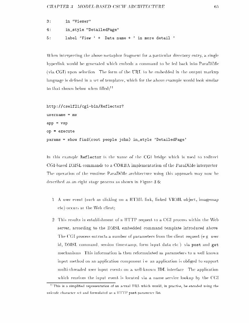
CHAPTER 3. MODEL-BASED CSCW ARCHITECTURE 653: in "Viewer"4: in_style "DetailedPage"5: label 'View ' + Data.name + ' in more detail.'When interpreting the above metaphor fragment for a particular directory entry, a singlehyperlink would be generated which embeds a command to be fed back into ParaDiMe(via CGI) upon selection. The form of the URL to be embedded in the output markuplanguage is de�ned in a set of templates, which for the above example would look similarto that shown below when �lled;11http://cself21/cgi-bin/Reflector?username = msapp = vspop = executeparams = show find(root.people.john) in_style 'DetailedPage'In this example Reflector is the name of the CGI bridge which is used to redirectCGI-based DMSL commands to a CORBA implementation of the ParaDiMe interpreter.The operation of the runtime ParaDiMe architecture using this approach may now bedescribed as an eight stage process as shown in Figure 3.6;1. A user event (such as clicking on a HTML link, linked VRML object, imagemapetc) occurs at the Web client;2. This results in establishment of a HTTP request to a CGI process within the Webserver, according to the DMSL embedded command template introduced above.The CGI process extracts a number of parameters from the client request (e.g. userid, DMSL command, session timestamp, form input data etc.) via post and getmechanisms. This information is then reformulated as parameters to a well knowninput method on an application component i.e. an application is obliged to supportmulti-threaded user input events on a well-known IDL interface. The applicationwhich receives the input event is located via a name service lookup by the CGI11This is a simpli�ed representation of an actual URL which would, in practise, be encoded using theunicode character set and formulated as a HTTP post parameter list.
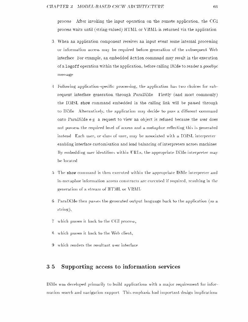
CHAPTER 3. MODEL-BASED CSCW ARCHITECTURE 66process. After invoking the input operation on the remote application, the CGIprocess waits until (string-valued) HTML or VRML is returned via the application.3. When an application component receives an input event some internal processingor information access may be required before generation of the subsequent Webinterface. For example, an embedded Action command may result in the executionof a logoff operation within the application, before calling DiMe to render a goodbyemessage.4. Following application-speci�c processing, the application has two choices for sub-sequent interface generation through ParaDiMe. Firstly (and most commonly)the DMSL show command embedded in the calling link will be passed throughto DiMe. Alternatively, the application may decide to pass a di�erent commandonto ParaDiMe e.g. a request to view an object is refused because the user doesnot possess the required level of access and a metaphor re ecting this is generatedinstead. Each user, or class of user, may be associated with a DMSL interpreter{enabling interface customisation and load balancing of interpreters across machines.By embedding user identi�ers within URLs, the appropriate DiMe interpreter maybe located.5. The show command is then executed within the appropriate DiMe interpreter andin-metaphor information access constructs are executed if required, resulting in thegeneration of a stream of HTML or VRML.6. ParaDiMe then passes the generated output language back to the application (as astring),7. which passes it back to the CGI process,8. which passes it back to the Web client,9. which renders the resultant user interface.3.5 Supporting access to information servicesDiMe was developed primarily to build applications with a major requirement for infor-mation search and navigation support. This emphasis had important design implications
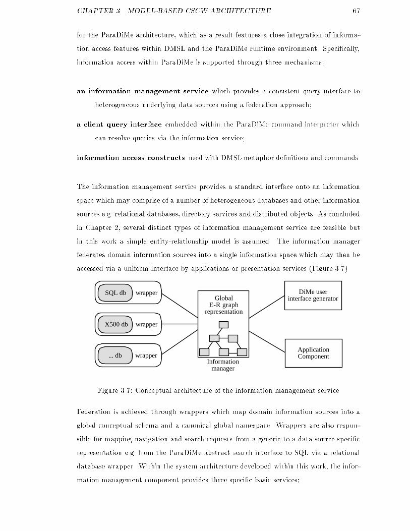
CHAPTER 3. MODEL-BASED CSCW ARCHITECTURE 67for the ParaDiMe architecture, which as a result features a close integration of informa-tion access features within DMSL and the ParaDiMe runtime environment. Speci�cally,information access within ParaDiMe is supported through three mechanisms;an information management service which provides a consistent query interface toheterogeneous underlying data sources using a federation approach;a client query interface embedded within the ParaDiMe command interpreter whichcan resolve queries via the information service;information access constructs used with DMSL metaphor de�nitions and commands.The information management service provides a standard interface onto an informationspace which may comprise of a number of heterogeneous databases and other informationsources e.g. relational databases, directory services and distributed objects. As concludedin Chapter 2, several distinct types of information management service are feasible butin this work a simple entity-relationship model is assumed. The information managerfederates domain information sources into a single information space which may then beaccessed via a uniform interface by applications or presentation services (Figure 3.7).... db wrapper
SQL db wrapper
X500 db wrapper
DiMe userinterface generator
ApplicationComponent
GlobalE-R graph
representation
InformationmanagerFigure 3.7: Conceptual architecture of the information management serviceFederation is achieved through wrappers which map domain information sources into aglobal conceptual schema and a canonical global namespace. Wrappers are also respon-sible for mapping navigation and search requests from a generic to a data source speci�crepresentation e.g. from the ParaDiMe abstract search interface to SQL via a relationaldatabase wrapper. Within the system architecture developed within this work, the infor-mation management component provides three speci�c basic services;
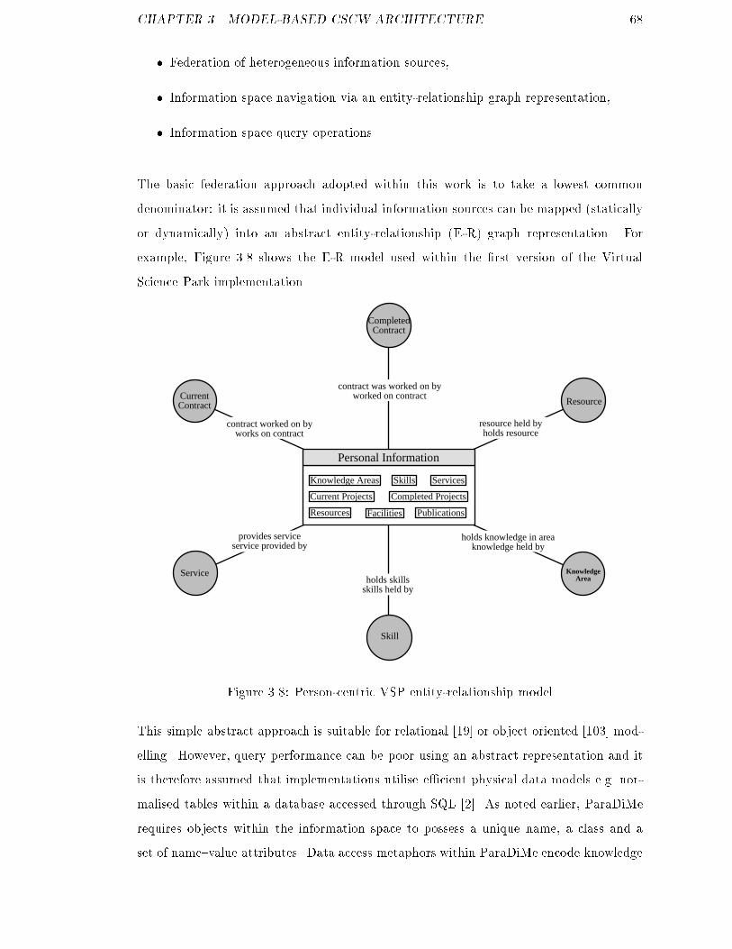
CHAPTER 3. MODEL-BASED CSCW ARCHITECTURE 68� Federation of heterogeneous information sources,� Information space navigation via an entity-relationship graph representation,� Information space query operations.The basic federation approach adopted within this work is to take a lowest commondenominator: it is assumed that individual information sources can be mapped (staticallyor dynamically) into an abstract entity-relationship (E-R) graph representation. Forexample, Figure 3.8 shows the E-R model used within the �rst version of the VirtualScience Park implementation.Skill
Service
Resource
KnowledgeArea
Personal Information
holds knowledge in areaknowledge held by
holds skillsskills held by
provides serviceservice provided by
contract worked on byworks on contract
contract was worked on byworked on contract
resource held byholds resource
CurrentContract
Current Projects Completed Projects
Knowledge Areas Skills Services
Resources Facilities
CompletedContract
Publications
Figure 3.8: Person-centric VSP entity-relationship modelThis simple abstract approach is suitable for relational [19] or object oriented [103] mod-elling. However, query performance can be poor using an abstract representation and itis therefore assumed that implementations utilise e�cient physical data models e.g. nor-malised tables within a database accessed through SQL [2]. As noted earlier, ParaDiMerequires objects within the information space to possess a unique name, a class and aset of name{value attributes. Data access metaphors within ParaDiMe encode knowledge
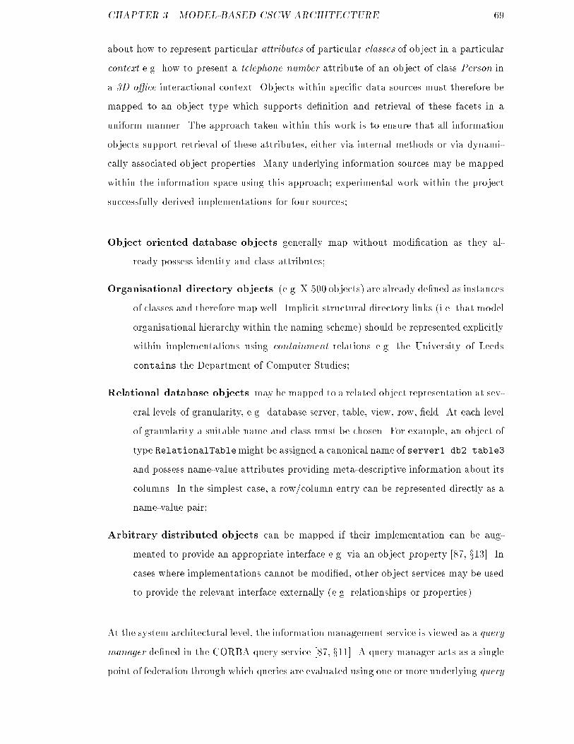
CHAPTER 3. MODEL-BASED CSCW ARCHITECTURE 69about how to represent particular attributes of particular classes of object in a particularcontext e.g. how to present a telephone number attribute of an object of class Person ina 3D o�ce interactional context. Objects within speci�c data sources must therefore bemapped to an object type which supports de�nition and retrieval of these facets in auniform manner. The approach taken within this work is to ensure that all informationobjects support retrieval of these attributes, either via internal methods or via dynami-cally associated object properties. Many underlying information sources may be mappedwithin the information space using this approach; experimental work within the projectsuccessfully derived implementations for four sources;Object oriented database objects generally map without modi�cation as they al-ready possess identity and class attributes;Organisational directory objects (e.g. X.500 objects) are already de�ned as instancesof classes and therefore map well. Implicit structural directory links (i.e. that modelorganisational hierarchy within the naming scheme) should be represented explicitlywithin implementations using containment relations e.g. the University of Leedscontains the Department of Computer Studies;Relational database objects may be mapped to a related object representation at sev-eral levels of granularity, e.g. database server, table, view, row, �eld. At each levelof granularity a suitable name and class must be chosen. For example, an object oftype RelationalTablemight be assigned a canonical name of server1.db2.table3and possess name-value attributes providing meta-descriptive information about itscolumns. In the simplest case, a row/column entry can be represented directly as aname-value pair;Arbitrary distributed objects can be mapped if their implementation can be aug-mented to provide an appropriate interface e.g. via an object property [87, x13]. Incases where implementations cannot be modi�ed, other object services may be usedto provide the relevant interface externally (e.g. relationships or properties).At the system architectural level, the information management service is viewed as a querymanager de�ned in the CORBA query service [87, x11]. A query manager acts as a singlepoint of federation through which queries are evaluated using one or more underlying query
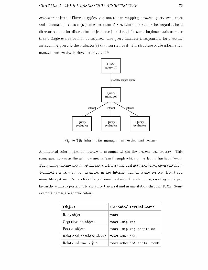
CHAPTER 3. MODEL-BASED CSCW ARCHITECTURE 70evaluator objects. There is typically a one-to-one mapping between query evaluatorsand information sources (e.g. one evaluator for relational data, one for organisationaldirectories, one for distributed objects etc.) although in some implementations morethan a single evaluator may be required. The query manager is responsible for directingan incoming query to the evaluator(s) that can resolve it. The structure of the informationmanagement service is shown in Figure 3.9.Query
evaluatorQuery
evaluatorQuery
evaluator
Querymanager
DiMequery i/f
globally scoped query
referralreferral referralFigure 3.9: Information management service architectureA universal information namespace is assumed within the system architecture. Thisnamespace serves as the primary mechanism through which query federation is achieved.The naming scheme chosen within this work is a canonical notation based upon textually-delimited syntax used, for example, in the Internet domain name service (DNS) andmany �le systems. Every object is positioned within a tree structure, creating an objecthierarchy which is particularly suited to traversal and manipulation through DiMe. Someexample names are shown below;Object Canonical textual nameRoot object rootOrganisation object root.ldap.vspPerson object root.ldap.vsp.people.msRelational database object root.odbc.db1Relational row object root.odbc.db1.table3.row8
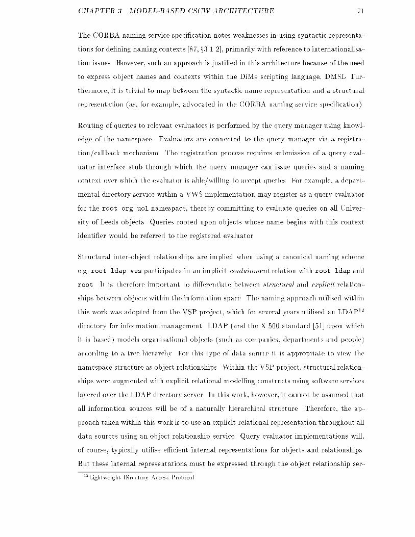
CHAPTER 3. MODEL-BASED CSCW ARCHITECTURE 71The CORBA naming service speci�cation notes weaknesses in using syntactic representa-tions for de�ning naming contexts [87, x3.1.2], primarily with reference to internationalisa-tion issues. However, such an approach is justi�ed in this architecture because of the needto express object names and contexts within the DiMe scripting language, DMSL. Fur-thermore, it is trivial to map between the syntactic name representation and a structuralrepresentation (as, for example, advocated in the CORBA naming service speci�cation).Routing of queries to relevant evaluators is performed by the query manager using knowl-edge of the namespace. Evaluators are connected to the query manager via a registra-tion/callback mechanism. The registration process requires submission of a query eval-uator interface stub through which the query manager can issue queries and a namingcontext over which the evaluator is able/willing to accept queries. For example, a depart-mental directory service within a VWS implementation may register as a query evaluatorfor the root.org.uol namespace, thereby committing to evaluate queries on all Univer-sity of Leeds objects. Queries rooted upon objects whose name begins with this contextidenti�er would be referred to the registered evaluator.Structural inter-object relationships are implied when using a canonical naming schemee.g. root.ldap.vws participates in an implicit containment relation with root.ldap androot. It is therefore important to di�erentiate between structural and explicit relation-ships between objects within the information space. The naming approach utilised withinthis work was adopted from the VSP project, which for several years utilised an LDAP12directory for information management. LDAP (and the X.500 standard [51] upon whichit is based) models organisational objects (such as companies, departments and people)according to a tree hierarchy. For this type of data source it is appropriate to view thenamespace structure as object relationships. Within the VSP project, structural relation-ships were augmented with explicit relational modelling constructs using software serviceslayered over the LDAP directory server. In this work, however, it cannot be assumed thatall information sources will be of a naturally hierarchical structure. Therefore, the ap-proach taken within this work is to use an explicit relational representation throughout alldata sources using an object relationship service. Query evaluator implementations will,of course, typically utilise e�cient internal representations for objects and relationships.But these internal representations must be expressed through the object relationship ser-12Lightweight Directory Access Protocol

CHAPTER 3. MODEL-BASED CSCW ARCHITECTURE 72vice upon externalisation.As relationships are modelled explicitly within the system architecture there is no tech-nical requirement for a syntactically speci�ed namespace. However, such an approachhas been found to be very useful when integrating information sources and working withDMSL scripts. Symbolic names are intuitive to manipulate within DiMe and also providea simple mechanism to delineate the information space.The information management service provides an E-R graph representation of the un-derlying information space through an object relationship service e.g. [87, x9]. Clientsof the information service (i.e. DiMe or application layer components) utilise this graphprimarily to navigate the information space, although support for arbitrary queries is alsoprovided.Navigational query operations are special forms of query which are rooted at a partic-ular object within the information space and traverse one or more relational linksto other objects. The root object plus the resultant object set together form aconnected graph. e.g. \from the VWS Organisation object, �nd all objects of classPerson linked by an Employs relation."Generalised query operations are scoped over the entire information space and the resultset may contain objects that are not explicitly related e.g. \�nd objects modi�ed thisweek."ParaDiMe is designed speci�cally to support navigational queries within structured infor-mation spaces. There are four basic database query operations which ParaDiMe requiresfrom the information management service in order to enable information space navigation;1. Retrieve an object by name,2. From an object, �nd all related objects of any class,3. From an object, �nd all related objects of a particular class,4. From an object, �nd all objects linked by a speci�c relational role.
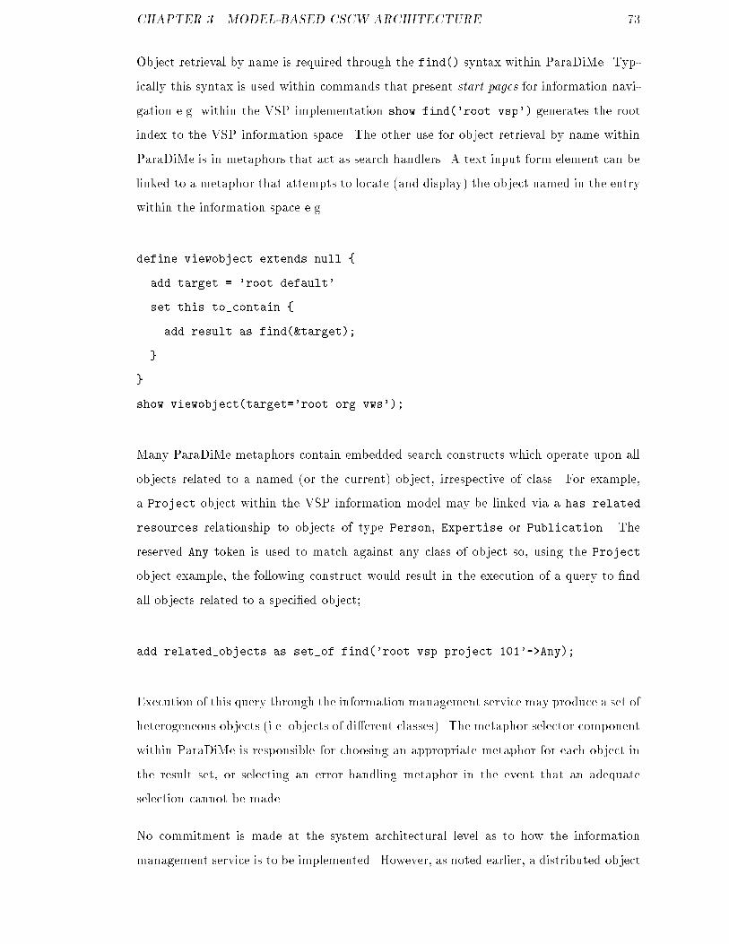
CHAPTER 3. MODEL-BASED CSCW ARCHITECTURE 73Object retrieval by name is required through the find() syntax within ParaDiMe. Typ-ically this syntax is used within commands that present start pages for information navi-gation e.g. within the VSP implementation show find('root.vsp') generates the rootindex to the VSP information space. The other use for object retrieval by name withinParaDiMe is in metaphors that act as search handlers. A text input form element can belinked to a metaphor that attempts to locate (and display) the object named in the entrywithin the information space e.g.define viewobject extends null {add target = 'root.default'set this to_contain {add result as find(&target);}}show viewobject(target='root.org.vws');Many ParaDiMe metaphors contain embedded search constructs which operate upon allobjects related to a named (or the current) object, irrespective of class. For example,a Project object within the VSP information model may be linked via a has relatedresources relationship to objects of type Person, Expertise or Publication. Thereserved Any token is used to match against any class of object so, using the Projectobject example, the following construct would result in the execution of a query to �ndall objects related to a speci�ed object;add related_objects as set_of find('root.vsp.project.101'->Any);Execution of this query through the information management service may produce a set ofheterogeneous objects (i.e. objects of di�erent classes). The metaphor selector componentwithin ParaDiMe is responsible for choosing an appropriate metaphor for each object inthe result set, or selecting an error handling metaphor in the event that an adequateselection cannot be made.No commitment is made at the system architectural level as to how the informationmanagement service is to be implemented. However, as noted earlier, a distributed object
CHAPTER 3. MODEL-BASED CSCW ARCHITECTURE 74architecture providing component services with the functionality of CORBAservices isassumed. There are several relevant common object services upon which the informationmanagement service is reliant, although how these services are actually constructed is animplementation issue;A Query service provides operations to retrieve and update objects within collectionssuch as databases [87, x11],A Relationship service enables explicit modelling of typed relationships between ob-jects and support for graphs of such relationships [87, x9],A Property service enables objects to be dynamically associated with named, typedvalues outside the static type system [87, x13].Within the CORBA query service, SQL and OQL [18] may be used as query languages.In this work, however, most queries are of a navigational nature and may involve di�erentunderlying information sources. It was beyond the scope of the work to implement afully functional query evaluator for a potentially complex and heterogeneously-structuredinformation space. A simple proprietary query syntax was therefore developed withinthe project. The syntax enables navigational searches within the information space to bespeci�ed textually according to the following syntax;(find <from> <direction> <objectfilter> <linkfilter> <genfilter>)from: the canonical name of the object within the information space at which the navi-gation is rooted (mandatory parameter),direction: the direction(s) along which to traverse object relations (mandatory param-eter),object�lter: a restriction on the class of objects to be returned (optional parameter),link�lter: a restriction on the object relationships to traverse (optional parameter),gen�lter: a source speci�c general search �lter which is understood by the target queryevaluator (optional parameter).
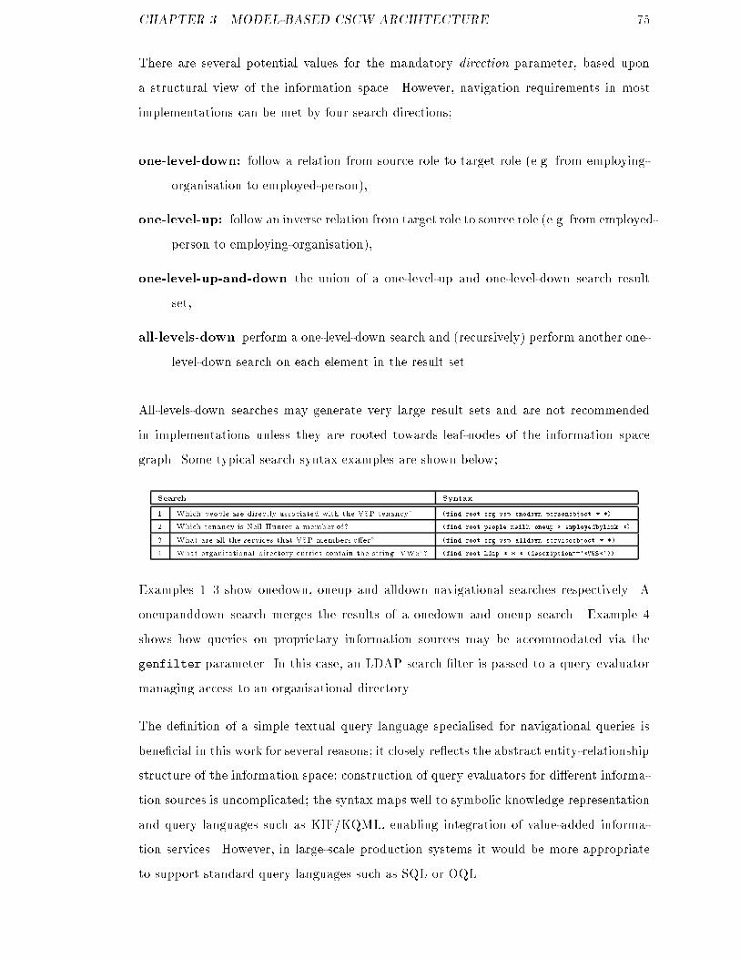
CHAPTER 3. MODEL-BASED CSCW ARCHITECTURE 75There are several potential values for the mandatory direction parameter, based upona structural view of the information space. However, navigation requirements in mostimplementations can be met by four search directions;one-level-down: follow a relation from source role to target role (e.g. from employing-organisation to employed-person),one-level-up: follow an inverse relation from target role to source role (e.g. from employed-person to employing-organisation),one-level-up-and-down the union of a one-level-up and one-level-down search resultset,all-levels-down perform a one-level-down search and (recursively) perform another one-level-down search on each element in the result set.All-levels-down searches may generate very large result sets and are not recommendedin implementations unless they are rooted towards leaf-nodes of the information spacegraph. Some typical search syntax examples are shown below;Search Syntax1 Which people are directly associated with the VSP tenancy? (find root.org.vsp onedown personobject * *)2 Which tenancy is Neil Hunter a member of? (find root.people.neilh oneup * employedbylink *)3 What are all the services that VSP members o�er? (find root.org.vsp alldown serviceobject * *)4 What organisational directory entries contain the string 'VWS'? (find root.ldap * * * (description=='*VWS*'))Examples 1{3 show onedown, oneup and alldown navigational searches respectively. Aoneupanddown search merges the results of a onedown and oneup search. Example 4shows how queries on proprietary information sources may be accommodated via thegenfilter parameter. In this case, an LDAP search �lter is passed to a query evaluatormanaging access to an organisational directory.The de�nition of a simple textual query language specialised for navigational queries isbene�cial in this work for several reasons; it closely re ects the abstract entity-relationshipstructure of the information space; construction of query evaluators for di�erent informa-tion sources is uncomplicated; the syntax maps well to symbolic knowledge representationand query languages such as KIF/KQML, enabling integration of value-added informa-tion services. However, in large-scale production systems it would be more appropriateto support standard query languages such as SQL or OQL.
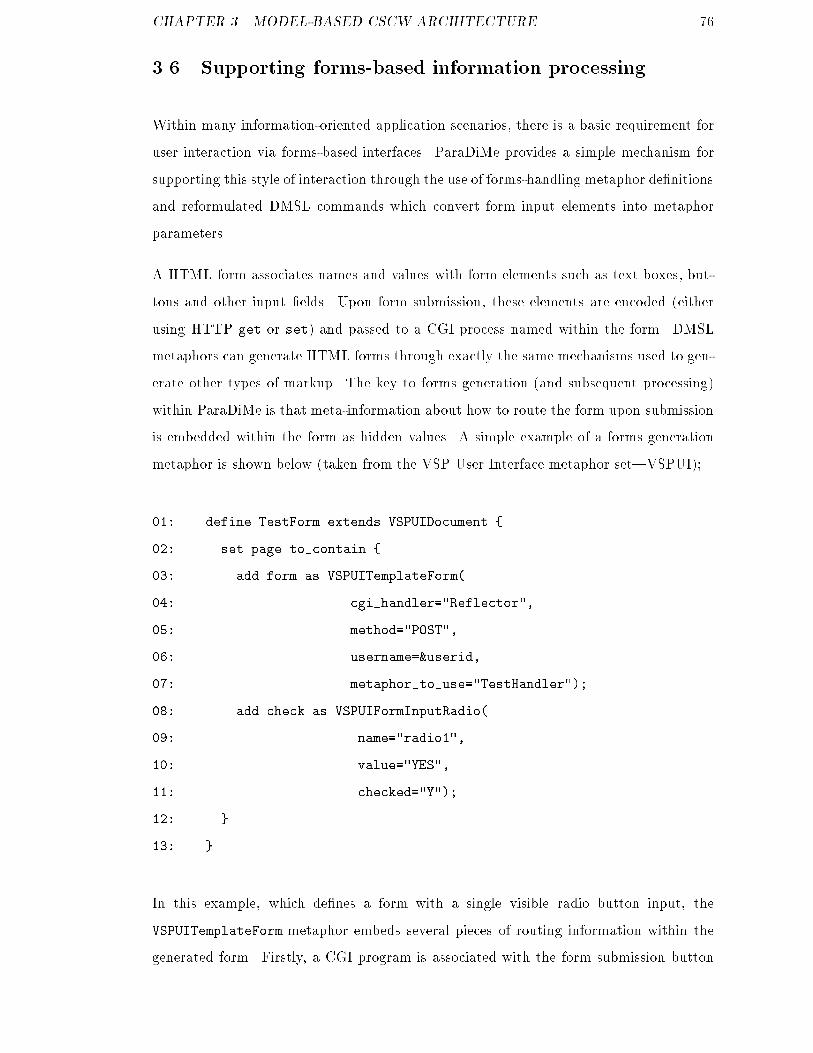
CHAPTER 3. MODEL-BASED CSCW ARCHITECTURE 763.6 Supporting forms-based information processingWithin many information-oriented application scenarios, there is a basic requirement foruser interaction via forms-based interfaces. ParaDiMe provides a simple mechanism forsupporting this style of interaction through the use of forms-handling metaphor de�nitionsand reformulated DMSL commands which convert form input elements into metaphorparameters.A HTML form associates names and values with form elements such as text boxes, but-tons and other input �elds. Upon form submission, these elements are encoded (eitherusing HTTP get or set) and passed to a CGI process named within the form. DMSLmetaphors can generate HTML forms through exactly the same mechanisms used to gen-erate other types of markup. The key to forms generation (and subsequent processing)within ParaDiMe is that meta-information about how to route the form upon submissionis embedded within the form as hidden values. A simple example of a forms generationmetaphor is shown below (taken from the VSP User Interface metaphor set|VSPUI);01: define TestForm extends VSPUIDocument {02: set page to_contain {03: add form as VSPUITemplateForm(04: cgi_handler="Reflector",05: method="POST",06: username=&userid,07: metaphor_to_use="TestHandler");08: add check as VSPUIFormInputRadio(09: name="radio1",10: value="YES",11: checked="Y");12: }13: }In this example, which de�nes a form with a single visible radio button input, theVSPUITemplateForm metaphor embeds several pieces of routing information within thegenerated form. Firstly, a CGI program is associated with the form submission button

CHAPTER 3. MODEL-BASED CSCW ARCHITECTURE 77(line 4) and a CGI method13 (line 5). Secondly, a ParaDiMe user name is associated withthe metaphor in order to route the processing request to the correct interpreter withinParaDiMe (line 6). The user id may be speci�ed as a literal string but is more usuallyspeci�ed as the current user which is represented in DMSL through a special token|&userid. Finally, a handler metaphor is speci�ed for the form (line 7). The handlermetaphor must de�ne a variable slot for each input element in form.Upon form submission at the user interface, the form data is passed through CGI (andthe object bridge) to the application named as the form handler. The application thenreads the submitted form values on standard input and performs any required processinge.g. object updating within the information space. When application speci�c processingis completed, the application synthesises a DMSL show command from the form inputelement values and the meta-information embedded by the generating metaphor. Thestructure of the synthesised command, together with a usage example, is shown below;show metaphor_to_use(element=value, element=value...)show TestHandler(radio1=`YES`)The show command is then routed to the relevant ParaDiMe interpreter and the outputresults returned to the client in the standard manner. The forms handling subsystemwithin ParaDiMe provides a useful mechanism for implementing form-based interactionwithin applications. However, care must be taken by system builders to ensure that formgeneration metaphors remain consistent with their associated handlers. In order to ad-dress this issue, early experimental work has attempted to automate de�nition of formsgeneration and handler DMSL metaphor de�nitions directly from database schemata.This provides a quick way to generate accurate forms metaphors but creates a furtherlevel of indirection in the interface generation process i.e. generation of a model to gen-erate an interface. This approach has been useful for applications where the informationmodel remains static, but a better strategy would be to develop constructs which enablenew metaphors to be synthesised dynamically when new objects are encountered. Thisstrategy, which should be explored in future work, could move DiMe towards becoming ageneric object browser in dynamic information environments.13It is normally safer to use post rather than get.
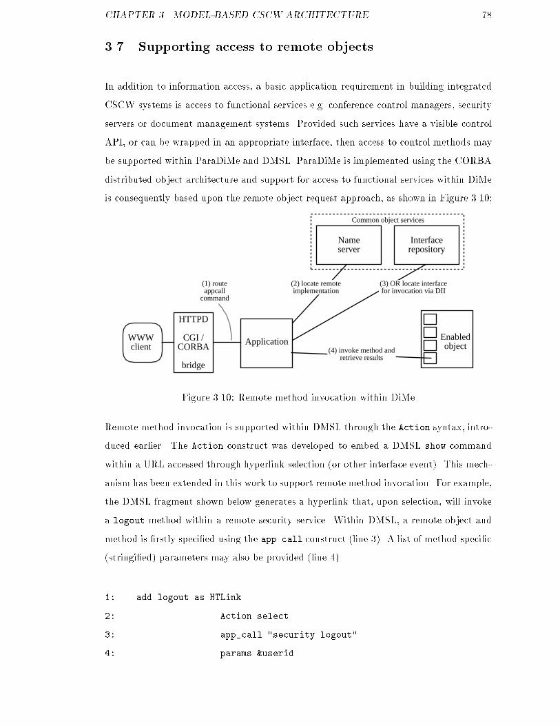
CHAPTER 3. MODEL-BASED CSCW ARCHITECTURE 783.7 Supporting access to remote objectsIn addition to information access, a basic application requirement in building integratedCSCW systems is access to functional services e.g. conference control managers, securityservers or document management systems. Provided such services have a visible controlAPI, or can be wrapped in an appropriate interface, then access to control methods maybe supported within ParaDiMe and DMSL. ParaDiMe is implemented using the CORBAdistributed object architecture and support for access to functional services within DiMeis consequently based upon the remote object request approach, as shown in Figure 3.10;WWWclient
Enabledobject
Interfacerepository
(1) routeappcall
command
(2) locate remoteimplementation
(3) OR locate interfacefor invocation via DII
Application(4) invoke method and
retrieve results
HTTPD
CGI /CORBA
bridge
Common object services
Nameserver
Figure 3.10: Remote method invocation within DiMeRemote method invocation is supported within DMSL through the Action syntax, intro-duced earlier. The Action construct was developed to embed a DMSL show commandwithin a URL accessed through hyperlink selection (or other interface event). This mech-anism has been extended in this work to support remote method invocation. For example,the DMSL fragment shown below generates a hyperlink that, upon selection, will invokea logout method within a remote security service. Within DMSL, a remote object andmethod is �rstly speci�ed using the app call construct (line 3). A list of method speci�c(stringi�ed) parameters may also be provided (line 4).1: add logout as HTLink2: Action select3: app_call "security.logout"4: params &userid

CHAPTER 3. MODEL-BASED CSCW ARCHITECTURE 795: label "Sign off from the system"At runtime, the object bridge initially routes the request to the application componentspeci�ed within the Action template (step 1 in Figure 3.10). The application then usesthe CORBA name service to bind to the service implementation identi�ed within themetaphor de�nition (e.g. the security service implementation) (step 2). An interfacerepository lookup may also be required where an interface is not known to the applica-tion a priori (step 3). After binding to the remote interface, the application may thenlocate and invoke the method named within the app call de�nition (step 4). Follow-ing method invocation, an application is responsible for calling ParaDiMe to generate anappropriate resultant interface|where the app call construct is used in existing appli-cations, ParaDiMe generates a simple \operation performed successfully" message.3.8 Supporting access to collaborative toolsThe major application of remote method invocation mechanisms within ParaDiMe is insupporting execution and subsequent control and teardown of collaborative working toolse.g. shared whiteboards, videoconferencing tools etc. as shown in Figure 3.11.Groupwareexecutionmanager
User
WWWClient
CommsClient
User WWWClient
CommsClient
ApplicationLayer
HTTPD
CGI /CORBA
BRIDGE
HTTPD
CGI /CORBA
BRIDGE
DiMe server
Information manager
register
execute
Registration profiles
Groupware access metaphors
Figure 3.11: Collaborative tool control subsystem

CHAPTER 3. MODEL-BASED CSCW ARCHITECTURE 80Groupware session control is, however, di�erentiated from the majority of other uses forremote method invocation within ParaDiMe by a requirement for control of client-sidefunctional components. For example, consider establishment of a shared whiteboard ses-sion between two users of a ParaDiMe-based group support system. In order to supportthis scenario, ParaDiMe must �rstly be informed that a user wishing to engage in commu-nication is logged in and willing to accept connections from other users. Secondly, whena calling user wishes to establish a whiteboard connection with somebody else, ParaDiMerequires a mechanism for executing client-side whiteboard tools on each client machineand pointing the clients at each other.The approach taken within this work was to develop a standalone client-side componentthat is separate to the Web browser through which the user typically interacts. Thecommunications client registers a callback interface with a remote conference controlcomponent, which is then used to launch and control collaborative tools. As noted earlierin the thesis, the exibility of this mechanism is ultimately constrained by the level ofexternal control available in particular tools. In a proof-of-concept implementation forexample, the Unix wb shared whiteboard tool was integrated as this provided a simplecommand line control interface. Future work may, however, investigate more sophisticatedconference control schemes such as the VWS conferencing architecture proposed by Hunter[48].3.9 Application development methodologyParaDiMe is useful in building integrated internet-based CSCW systems. Development ofsuch applications within ParaDiMe is most appropriately progressed through an iterativeRapid Application Development (RAD) approach, as shown in Figure 3.12. However,designing and building ParaDiMe applications requires di�erent development emphasisthrough the design-build-evaluate lifecycle in comparison to conventional software engi-neering projects. As a development environment, ParaDiMe includes a standard libraryof re-usable CSCW services and generic metaphor de�nitions which describe how accessto those services may be provided via a Web user interface. An initial system design andbuild activity using ParaDiMe therefore starts with an architectural design activity inwhich core services are identi�ed and brought together. Once a set of general services
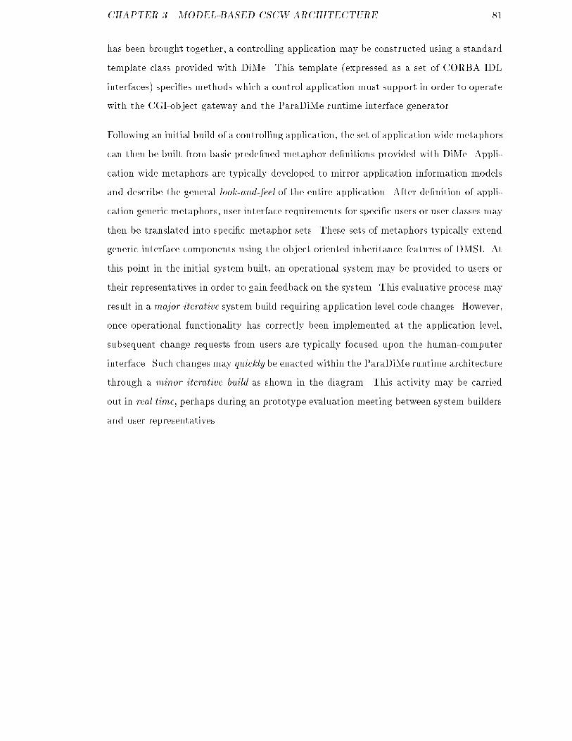
CHAPTER 3. MODEL-BASED CSCW ARCHITECTURE 81has been brought together, a controlling application may be constructed using a standardtemplate class provided with DiMe. This template (expressed as a set of CORBA IDLinterfaces) speci�es methods which a control application must support in order to operatewith the CGI-object gateway and the ParaDiMe runtime interface generator.Following an initial build of a controlling application, the set of application wide metaphorscan then be built from basic prede�ned metaphor de�nitions provided with DiMe. Appli-cation wide metaphors are typically developed to mirror application information modelsand describe the general look-and-feel of the entire application. After de�nition of appli-cation generic metaphors, user interface requirements for speci�c users or user classes maythen be translated into speci�c metaphor sets. These sets of metaphors typically extendgeneric interface components using the object oriented inheritance features of DMSL. Atthis point in the initial system built, an operational system may be provided to users ortheir representatives in order to gain feedback on the system. This evaluative process mayresult in a major iterative system build requiring application level code changes. However,once operational functionality has correctly been implemented at the application level,subsequent change requests from users are typically focused upon the human-computerinterface. Such changes may quickly be enacted within the ParaDiMe runtime architecturethrough a minor iterative build as shown in the diagram. This activity may be carriedout in real time, perhaps during an prototype evaluation meeting between system buildersand user representatives.
CHAPTER 3. MODEL-BASED CSCW ARCHITECTURE 82Capture
userrequirements
design serviceand application
architecture
(re)build generic and app-wide
metaphors
(re)build rolespecific metaphors
(re)buildapplication
layer
Integrate andevaluate
initialsystembuild
minoriterativerebuild
majoriterativerebuild
Freeze forengineering further design
requiredFigure 3.12: ParaDiMe development methodology
CHAPTER 3. MODEL-BASED CSCW ARCHITECTURE 833.10 SummaryThis chapter has discussed the ParaDiMe model-based CSCW architecture, which at-tempts to raise the level of abstraction at which integrated internet CSCW applicationsare built and subsequently modi�ed over time. ParaDiMe provides explicit architecturalsupport for building cooperative systems via component-based models which describeuser interaction with functional services. The ParaDiMe architecture is comprised of fourmajor components;A library of user interface models is de�ned using a purpose-built modelling lan-guage which describes how system users interact with application and componentservices;A runtime interface generation service provides application user interfaces at run-time from user interface models de�ned using the modelling language, directed bycommands from the application-speci�c control component;A library of CSCW services provides implementations of CSCW services that arebuild speci�cally to enable their re-use in di�erent applications;Application components implement application speci�c functionality and integrateaccess to general CSCW services where required.The Display Metaphor Scripting Language (DMSL) was introduced as the modellinglanguage component of the ParaDiMe architecture. The relationship between DMSL,the DiMe object model and the ParaDiMe runtime interface generation component wasdiscussed. The runtime architecture subsystems supporting user interactivity were de-scribed. Finally, a simple methodology for developing ParaDiMe applications within aRAD framework was proposed. Chapter 4 proceeds by describing the application ofParaDiMe towards a case study cooperative working scenario. Speci�cally, it presentsa proof-of-concept ParaDiMe-based implementation of an application to support groupwork within a telecommunications business process.
Chapter 4Case study implementation4.1 IntroductionChapter 3 described the system architecture of a model-based architecture for constructionof integrated CSCW systems from modular and reusable components. As stated in theintroduction to this thesis, the architecture seeks speci�cally to address three problemsinherent in many existing CSCW system construction environments,1. CSCW services are not reusable,2. User perspectives are not adequately re ected during prototyping,3. Evolving user requirements are not adequately re ected in evolving live systems.In order to assess the research hypothesis that a model-based system construction ap-proach can o�er a solution to these problems, a proof-of-concept implementation of themodel-based architecture was constructed. The implementation was then applied to acase study cooperative working scenario and a number of use cases developed in order todemonstrate the utility of the approach towards solving the research problems. A prac-tical demonstration of the architecture based around these use cases formed the basis forassessment of the research with a potential user community within BT Laboratories, asreported in Chapter 5. 84
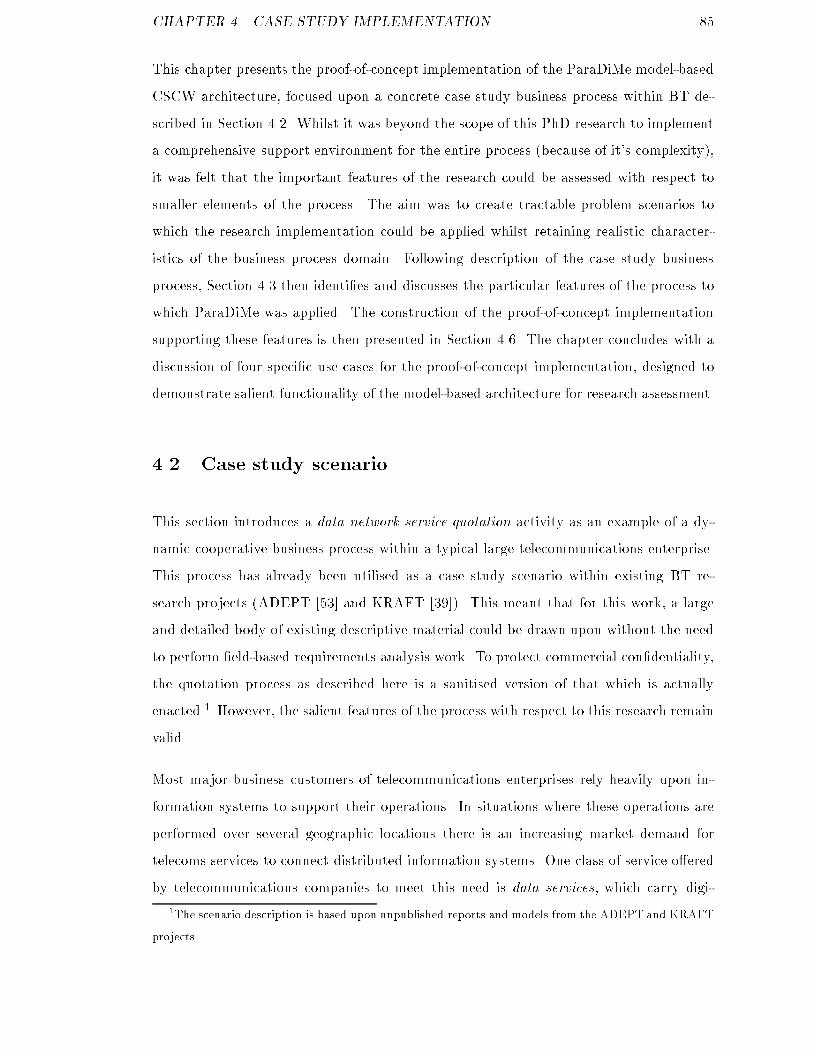
CHAPTER 4. CASE STUDY IMPLEMENTATION 85This chapter presents the proof-of-concept implementation of the ParaDiMe model-basedCSCW architecture, focused upon a concrete case study business process within BT de-scribed in Section 4.2. Whilst it was beyond the scope of this PhD research to implementa comprehensive support environment for the entire process (because of it's complexity),it was felt that the important features of the research could be assessed with respect tosmaller elements of the process. The aim was to create tractable problem scenarios towhich the research implementation could be applied whilst retaining realistic character-istics of the business process domain. Following description of the case study businessprocess, Section 4.3 then identi�es and discusses the particular features of the process towhich ParaDiMe was applied. The construction of the proof-of-concept implementationsupporting these features is then presented in Section 4.6. The chapter concludes with adiscussion of four speci�c use cases for the proof-of-concept implementation, designed todemonstrate salient functionality of the model-based architecture for research assessment.4.2 Case study scenarioThis section introduces a data network service quotation activity as an example of a dy-namic cooperative business process within a typical large telecommunications enterprise.This process has already been utilised as a case study scenario within existing BT re-search projects (ADEPT [53] and KRAFT [39]). This meant that for this work, a largeand detailed body of existing descriptive material could be drawn upon without the needto perform �eld-based requirements analysis work. To protect commercial con�dentiality,the quotation process as described here is a sanitised version of that which is actuallyenacted.1 However, the salient features of the process with respect to this research remainvalid.Most major business customers of telecommunications enterprises rely heavily upon in-formation systems to support their operations. In situations where these operations areperformed over several geographic locations there is an increasing market demand fortelecoms services to connect distributed information systems. One class of service o�eredby telecommunications companies to meet this need is data services, which carry digi-1The scenario description is based upon unpublished reports and models from the ADEPT and KRAFTprojects.

CHAPTER 4. CASE STUDY IMPLEMENTATION 86tal tra�c between end-user locations over public networks with some quality-of-service(QoS) guarantee. Although these services are delivered over infrastructure shared withother customers it appears to the customer that they have their own private network,but without the expense of maintenance. Such arrangements are often referred to asvirtual private networks (VPNs). Data service requirements vary greatly from job to job,dependent upon many constraining factors e.g. bandwidth, latency, availability, length ofcircuit, routing etc. Providing a quotation for such services requires resource coordinationthrough several related activities within the telecommunications company, as shown inFigure 4.1.The end-to-end quotation process is comprised of several ordered tasks, performed bya number of cooperating participant roles. The process is currently managed using aconventional work ow management system (WFMS). Figure 4.1 shows the control owof work through the end-to-end quote process.A job is initiated when a customer approaches the telecoms company for a quotation. Inthe �rst instance, customer details are captured by a customer handling centre andentered into the work ow system via a forms-based terminal interface. If the customer hasnot dealt with the telco before then a new customer details record is created, otherwisethe existing customer details record is located. Submission of customer details to thework ow system then triggers the next phase of the quotation process.Following submission of a customer details record, two activities are progressed in parallel.Because of the high potential cost of data service provision, the customer may bevetted through a credit reference agency. Whilst this check takes place, an accountmanager is assigned to elicit user requirements. Representatives are typically assignedby market sector and have good industry and portfolio knowledge. The account managerliaises with the customer and builds up a more detailed picture of their requirements.These are entered into the work ow environment via a forms interface and associatedwith the customer details record.
CHAPTER 4. CASE STUDY IMPLEMENTATION 87Capturecustomer
details
Capturecustomer
requirements
Identifyserviceprofile
Vetcustomer
Analyserequirements
SurveyCPE
ProvideQuote
Designnetwork
Legalreview
?
?
?
?
Customer Customer
X
X
is legal
surveyrequired
portfolioitem
parallel
customer ok yesno
noFigure 4.1: Provision of quotations for data network services

CHAPTER 4. CASE STUDY IMPLEMENTATION 88Providing the customer has been vetted successfully, the service requirements pro�leis identi�ed. Here, the customer requirements are analysed to assess whether they canbe met from the existing telco service portfolio i.e. standard o�-the-shelf services. If thisis the case, a quotation can be initiated immediately and forwarded to the customer|thereby terminating the quotation job.If the customer requirements cannot be met from an existing portfolio service, a datanetwork design must be created in order to provide a customised solution. At this point,a network design team is assigned to the job and detailed network analysis and designis conducted. Whilst this is underway, a parallel review is conducted by a legal teamto ensure that the emerging design does not contravene relevant legislation (it is, forexample, apparently illegal to carry encrypted network tra�c through some parts ofEurope). During the design stage, the account manager mediates between the customerand the various cooperating groups within the telco (e.g. design team, legal advisors andtechnical support). If the parallel secondary requirements analysis and legal review issuccessful, a detailed design stage is initiated.In the detailed network design activity, the design team are responsible for producinga customised network architecture that meets the customer requirements. If it is deemednecessary during the secondary requirements analysis phase, the customer premises equip-ment (CPE) is surveyed on-site by engineers to provide input into the detailed networkdesign activity.Upon initiation of the detailed design activity, the design team transfer the customerdetails and requirements records from the main work ow system to a (textual) designdatabase, controlled by an account manager. During the design activity, the design teamcollaborate using a range of heterogeneous information sources and tools. A designer will,for example, require access to information on geographical site location, protocols, vendorequipment, design guidelines, network performance characteristics etc. Throughout thedesign process, the account manager elicits further requirements from the customer asneeded and feeds back progress on the design. Because of the complexity of the designactivity, there is still signi�cant reliance upon paper-based communication and processcoordination at this stage.

CHAPTER 4. CASE STUDY IMPLEMENTATION 89Once the design team have formulated a bespoke network design for the customer, apro�le of that design is fed back into the main work ow management environment anda customised quotation prepared. The quotation is then delivered back to the cus-tomer and the process terminates. Related installation, testing and billing processes aresubsequently enacted if the customer accepts the quotation.4.3 End-user perspectives and application stakeholdersProvision of quotations for data network services is an involved process requiring struc-tured and ad-hoc collaboration between a number of di�erent groups within the telco.Collaboration occurs within a highly heterogeneous information and systems environment.The inherent complexity of the process (although simpli�ed here) is re ected in the vari-ety of systems used to support the real process. Cooperating groups often utilise internalsystems from which information is transferred to the major work ow environment as andwhen required.Several distinct roles must cooperate in order to provide a customer quotation (e.g. cus-tomer handling centre operative, account manager, network designer and legal advisor).These roles have di�erent skills, expertise, responsibilities and perspectives on the overallprocess. These di�erences are re ected in di�erent requirements from the systems usedto coordinate the process;the customer handling clerk handles initial enquiries (e.g. in a telesales environment)and enters customer details onto a form, submission of which triggers the quotationprocess. No further functionality is required of the support environment for thisrole.the account manager the account manager is responsible for a managing a number ofjobs and mediating between customers and the assigned technical teams. They areprimarily interested in tracking end-to-end job progress and are unconcerned withthe highly technical content of the network design.the network designer utilises a wide range of tools and information sources to create abespoke network design. The design team need to share information and collaborate
CHAPTER 4. CASE STUDY IMPLEMENTATION 90internally, whilst liaising with the account manager and legal advisor as the designprogresses.the legal advisor uses a summary representation of the proposed design to assess po-tential legal rami�cations. In making this assessment, they typically communicateon an ad-hoc basis with the design group during the secondary requirements analysisphase.One reason that di�erent groups within the real process support environment utilise inter-nal work management systems is that a single conventional work ow management system(WFMS) cannot easily meet contrasting per-role requirements.2 Facilities exist withinmany work ow systems to build customised interfaces for particular classes of users, butthe development e�ort required to support this heterogeneity over time as requirementsdynamically evolve is often prohibitive (unless support environment customisation addssigni�cant value in process enactment). When constructing the process-support applica-tion, as with any system, end-user requirements are of central importance. The majortarget users in this research are those responsible for creating and subsequently managingthe environment which most appropriately meets the needs of their end-users. As notedearlier, this work seeks speci�cally to consider dynamic applications domains in whichchanging requirements must be fed back into support systems in an e�ective manner. Anumber of scenarios within the data services quotation process exemplify this. For in-stance, a new networking technology may be introduced which changes the structure of thetelco product portfolio; cooperating groups may relocate to di�erent o�ce locations lead-ing to a changing requirements for communications tools; a new (similar) service mightbe introduced using the existing process as a template. Within the simpli�ed businessprocess support scenario considered here, three major stakeholders may be identi�ed;� Process designer� System manager� End user role (or representative)2This observation is not unique to data network quotation provision of course; the process as describedfor this work is fairly generic and similar situations arise in many business processes within typical largeenterprises.
CHAPTER 4. CASE STUDY IMPLEMENTATION 91The process designer is responsible for analysing business requirements and creating acoordinated set of activities through which the business requirements may be met e.g. thedesigner models the quotation provision process as shown in Figure 4.1. The systemmanager is then responsible for creating and managing a system-based enactment en-vironment from this business process speci�cation which re ects end user requirementse.g. the system manager builds a work ow system to enact the process de�nition createdby the process designer.4.4 Case study implementation requirementsThe case study implementation attempted to demonstrate the utility of mechanismswithin the model-based architecture in supporting participatory design and subsequentevolutionary maintenance of a realistic cooperative system. The goal of the implementa-tion was to enable assessment of the research according to the objectives stated in Chapter1. Hence, the implementation did not seek to deliver a comprehensive process-supportenvironment that could be used by end-users in a pilot study. Rather, the objective wasto enable exploration and experimental assessment of the key features of the model-basedapproach to cooperative systems prototyping and evolution.The remainder of this chapter describes the development of the ParaDiMe-based pro-totyping environment to support experimental assessment of the model-based approach,according to the simple development method introduced in Section 3. Section 4.5 �rstlydiscusses the information and process-oriented user requirements for the application. Sec-tion 4.6 then describes how these requirements may be met from reusable CSCW servicesand application-speci�c components. Section 4.7 considers the user interface metaphorsthat are required to support the application and describes the structure of the resultingmetaphor library.4.5 Application information modelsThe key feature of the application scenario is the requirement to augment (rather thanreplace) conventional WFMS process coordination services with a more complete processsupport environment, which more closely re ects di�ering end-user requirements. This
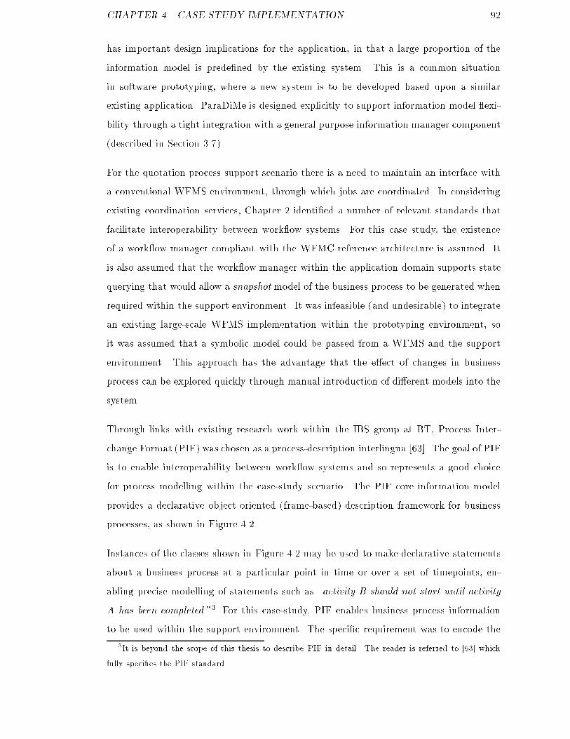
CHAPTER 4. CASE STUDY IMPLEMENTATION 92has important design implications for the application, in that a large proportion of theinformation model is prede�ned by the existing system. This is a common situationin software prototyping, where a new system is to be developed based upon a similarexisting application. ParaDiMe is designed explicitly to support information model exi-bility through a tight integration with a general purpose information manager component(described in Section 3.7).For the quotation process support scenario there is a need to maintain an interface witha conventional WFMS environment, through which jobs are coordinated. In consideringexisting coordination services, Chapter 2 identi�ed a number of relevant standards thatfacilitate interoperability between work ow systems. For this case study, the existenceof a work ow manager compliant with the WFMC reference architecture is assumed. Itis also assumed that the work ow manager within the application domain supports statequerying that would allow a snapshot model of the business process to be generated whenrequired within the support environment. It was infeasible (and undesirable) to integratean existing large-scale WFMS implementation within the prototyping environment, soit was assumed that a symbolic model could be passed from a WFMS and the supportenvironment. This approach has the advantage that the e�ect of changes in businessprocess can be explored quickly through manual introduction of di�erent models into thesystem.Through links with existing research work within the IBS group at BT, Process Inter-change Format (PIF) was chosen as a process-description interlingua [63]. The goal of PIFis to enable interoperability between work ow systems and so represents a good choicefor process modelling within the case-study scenario. The PIF core information modelprovides a declarative object oriented (frame-based) description framework for businessprocesses, as shown in Figure 4.2.Instances of the classes shown in Figure 4.2 may be used to make declarative statementsabout a business process at a particular point in time or over a set of timepoints, en-abling precise modelling of statements such as \activity B should not start until activityA has been completed."3 For this case-study, PIF enables business process informationto be used within the support environment. The speci�c requirement was to encode the3It is beyond the scope of this thesis to describe PIF in detail. The reader is referred to [63] whichfully speci�es the PIF standard.
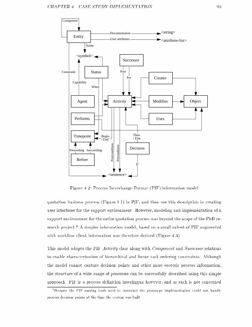
CHAPTER 4. CASE STUDY IMPLEMENTATION 93<symbol>
<sentence>
<string>
<attribute-list>
Documentation
User attributes
Name
Constraint
Pre
Post
WhenCapability
Component
Prec
ondi
tion
Post
cond
ition
Preceeding Succeeding
Begin/ End
Then/ Else
IfBefore
Timepoint
Performs
Agent ModifiesActivity Object
Decision
Creates
Successor
Entity
Status
Uses
Figure 4.2: Process Interchange Format (PIF) information modelquotation business process (Figure 4.1) in PIF, and then use this description in creatinguser interfaces for the support environment. However, modeling and implementation of asupport environment for the entire quotation process was beyond the scope of the PhD re-search project.4 A simpler information model, based on a small subset of PIF augmentedwith work ow client information was therefore derived (Figure 4.3).This model adopts the PIF Activity class along with Component and Successor relationsto enable characterisation of hierarchical and linear task ordering constraints. Althoughthe model cannot capture decision points and other more esoteric process information,the structure of a wide range of processes can be successfully described using this simpleapproach. PIF is a process de�nition interlingua however, and as such is not concerned4Because the PIF parsing tools used to construct the prototype implementation could not handleprocess decision points at the time the system was built.
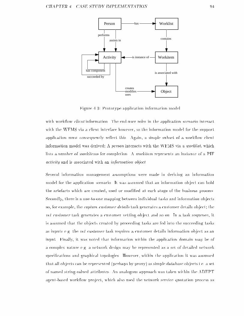
CHAPTER 4. CASE STUDY IMPLEMENTATION 94Person
Object
Workitem
Worklisthas
contains
is associated with
createsmodifiesuses
performs
assists in
is instance ofActivity
has component
succeeded byFigure 4.3: Prototype application information modelwith work ow client information. The end-user roles in the application scenario interactwith the WFMS via a client interface however, so the information model for the supportapplication must consequently re ect this. Again, a simple subset of a work ow clientinformation model was derived; A person interacts with the WFMS via a worklist, whichlists a number of workitems for completion. A workitem represents an instance of a PIFactivity and is associated with an information object.Several information management assumptions were made in deriving an informationmodel for the application scenario. It was assumed that an information object can holdthe artefacts which are created, used or modi�ed at each stage of the business process.Secondly, there is a one-to-one mapping between individual tasks and information objectsso, for example, the capture customer details task generates a customer details object; thevet customer task generates a customer vetting object and so on. In a task sequence, itis assumed that the objects created by preceeding tasks are fed into the succeeding tasksas inputs e.g. the vet customer task requires a customer details information object as aninput. Finally, it was noted that information within the application domain may be ofa complex nature e.g. a network design may be represented as a set of detailed networkspeci�cations and graphical topologies. However, within the application it was assumedthat all objects can be represented (perhaps by proxy) as simple database objects i.e. a setof named string-valued attributes. An analogous approach was taken within the ADEPTagent-based work ow project, which also used the network service quotation process as
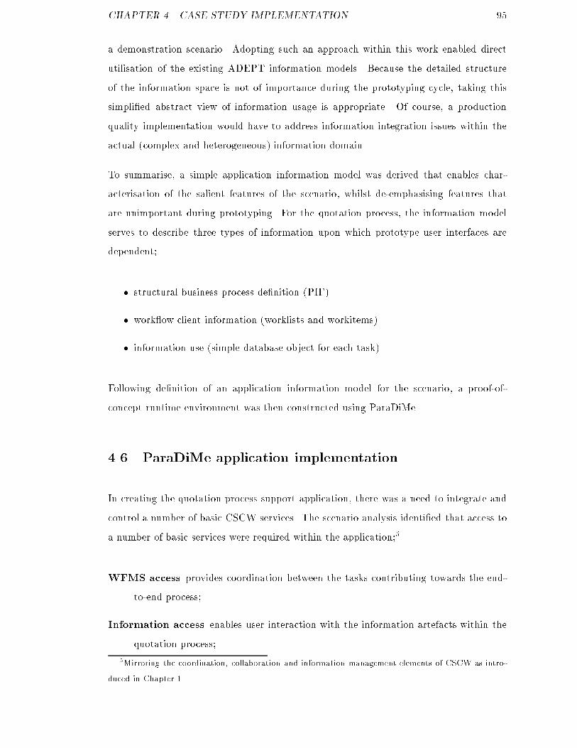
CHAPTER 4. CASE STUDY IMPLEMENTATION 95a demonstration scenario. Adopting such an approach within this work enabled directutilisation of the existing ADEPT information models. Because the detailed structureof the information space is not of importance during the prototyping cycle, taking thissimpli�ed abstract view of information usage is appropriate. Of course, a productionquality implementation would have to address information integration issues within theactual (complex and heterogeneous) information domain.To summarise, a simple application information model was derived that enables char-acterisation of the salient features of the scenario, whilst de-emphasising features thatare unimportant during prototyping. For the quotation process, the information modelserves to describe three types of information upon which prototype user interfaces aredependent;� structural business process de�nition (PIF)� work ow client information (worklists and workitems)� information use (simple database object for each task)Following de�nition of an application information model for the scenario, a proof-of-concept runtime environment was then constructed using ParaDiMe.4.6 ParaDiMe application implementationIn creating the quotation process support application, there was a need to integrate andcontrol a number of basic CSCW services. The scenario analysis identi�ed that access toa number of basic services were required within the application;5WFMS access provides coordination between the tasks contributing towards the end-to-end process;Information access enables user interaction with the information artefacts within thequotation process;5Mirroring the coordination, collaboration and information management elements of CSCW as intro-duced in Chapter 1.
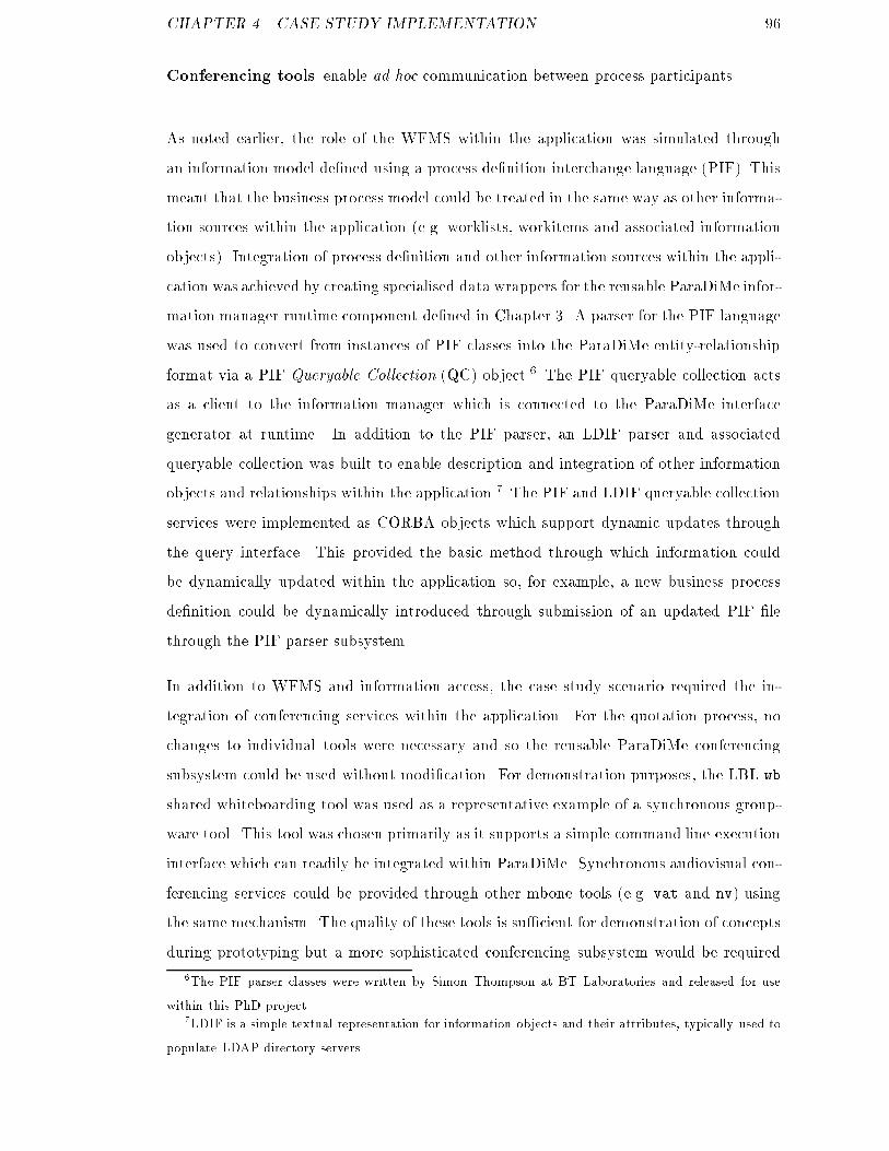
CHAPTER 4. CASE STUDY IMPLEMENTATION 96Conferencing tools enable ad hoc communication between process participants.As noted earlier, the role of the WFMS within the application was simulated throughan information model de�ned using a process de�nition interchange language (PIF). Thismeant that the business process model could be treated in the same way as other informa-tion sources within the application (e.g. worklists, workitems and associated informationobjects). Integration of process de�nition and other information sources within the appli-cation was achieved by creating specialised data wrappers for the reusable ParaDiMe infor-mation manager runtime component de�ned in Chapter 3. A parser for the PIF languagewas used to convert from instances of PIF classes into the ParaDiMe entity-relationshipformat via a PIF Queryable Collection (QC) object.6 The PIF queryable collection actsas a client to the information manager which is connected to the ParaDiMe interfacegenerator at runtime. In addition to the PIF parser, an LDIF parser and associatedqueryable collection was built to enable description and integration of other informationobjects and relationships within the application.7 The PIF and LDIF queryable collectionservices were implemented as CORBA objects which support dynamic updates throughthe query interface. This provided the basic method through which information couldbe dynamically updated within the application so, for example, a new business processde�nition could be dynamically introduced through submission of an updated PIF �lethrough the PIF parser subsystem.In addition to WFMS and information access, the case study scenario required the in-tegration of conferencing services within the application. For the quotation process, nochanges to individual tools were necessary and so the reusable ParaDiMe conferencingsubsystem could be used without modi�cation. For demonstration purposes, the LBL wbshared whiteboarding tool was used as a representative example of a synchronous group-ware tool. This tool was chosen primarily as it supports a simple command line executioninterface which can readily be integrated within ParaDiMe. Synchronous audiovisual con-ferencing services could be provided through other mbone tools (e.g. vat and nv) usingthe same mechanism. The quality of these tools is su�cient for demonstration of conceptsduring prototyping but a more sophisticated conferencing subsystem would be required6The PIF parser classes were written by Simon Thompson at BT Laboratories and released for usewithin this PhD project.7LDIF is a simple textual representation for information objects and their attributes, typically used topopulate LDAP directory servers.

CHAPTER 4. CASE STUDY IMPLEMENTATION 97within a production environment (e.g. the VWS conferencing architecture proposed in[48]).Following identi�cation of basic service requirements within the application scenario,reusable service implementations must be integrated within a controlling application-layer component. This component implements the control logic within the application,acting as a single sink for all user interface operations (via encoded DMSL commands) andsubsequent user interface generation through ParaDiMe. The application was customisedusing the generic ParaDiMe runtime architecture presented in Section 3. In implementinga support application for the quotation process, shown in Figure 4.4, two changes to thegeneric ParaDiMe architecture were made. Firstly, queryable collections for the PIF andLDIF domain information sources were constructed. Secondly, a controlling component(called the work ow helper) was written as a specialised implementation of the generalParaDiMe application template.The work ow helper component brings together the reusable services that are requiredwithin the application, providing three main services within the runtime environment;Information object update through forms: users interact with tasks and informa-tion objects via forms interfaces, thus there is a requirement to map form infor-mation back into the information space. This was implemented using the forms-interaction ParaDiMe subsystem.Conferencing subsystem control: the ParaDiMe conference control subsystem wasintegrated into the work ow helper application to enable business process partici-pants to collaborate in real-time. Collaboration requirements were modelled withinthe domain information model, by associating secondary roles with activities usingan assists relation. For example, collaboration between an account manager roleand the network design role during performance of the design activity could bespeci�ed by association of the account manager to the design activity via the assistsrelation. ParaDiMe can then use this information to create user interfaces withappropriately embedded communications requests. The work ow helper was usedto maintain a list of registered communication client interfaces (i.e. noting whichroles were available for conferencing), and executing tools via these interfaces uponreception of a conferencing request from a user.
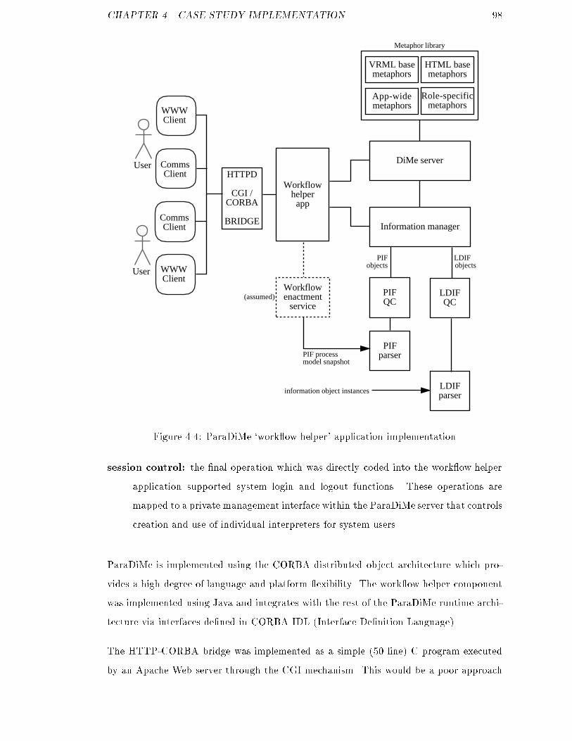
CHAPTER 4. CASE STUDY IMPLEMENTATION 98User
WWWClient
CommsClient
User WWWClient
CommsClient
HTTPD
CGI /CORBA
BRIDGEInformation manager
LDIFQC
PIF QC
LDIFparser
PIF parser
information object instances
PIFobjects
LDIFobjects
VRML basemetaphors
HTML basemetaphors
Role-specificmetaphors
App-widemetaphors
DiMe server
Metaphor library
Workflowenactment
service
PIF processmodel snapshot
Workflowhelper
app
(assumed)
Figure 4.4: ParaDiMe `work ow helper' application implementationsession control: the �nal operation which was directly coded into the work ow helperapplication supported system login and logout functions. These operations aremapped to a private management interface within the ParaDiMe server that controlscreation and use of individual interpreters for system users.ParaDiMe is implemented using the CORBA distributed object architecture which pro-vides a high degree of language and platform exibility. The work ow helper componentwas implemented using Java and integrates with the rest of the ParaDiMe runtime archi-tecture via interfaces de�ned in CORBA IDL (Interface De�nition Language).The HTTP-CORBA bridge was implemented as a simple (50 line) C program executedby an Apache Web server through the CGI mechanism. This would be a poor approach
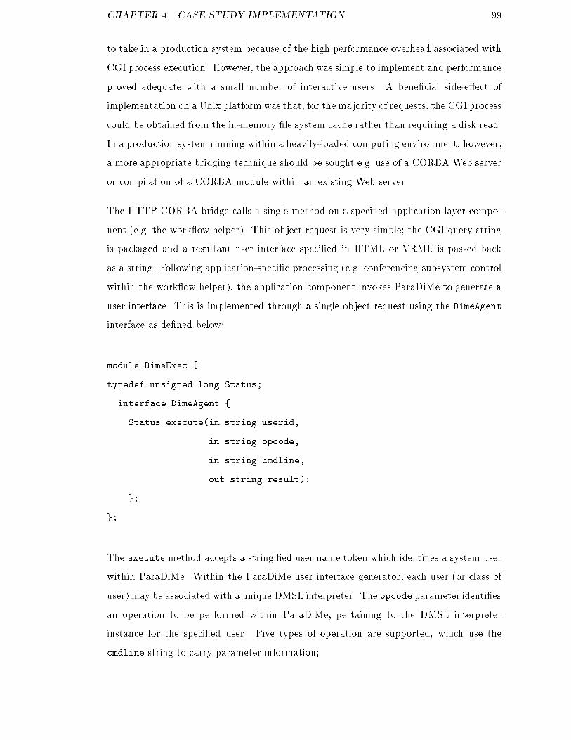
CHAPTER 4. CASE STUDY IMPLEMENTATION 99to take in a production system because of the high performance overhead associated withCGI process execution. However, the approach was simple to implement and performanceproved adequate with a small number of interactive users. A bene�cial side-e�ect ofimplementation on a Unix platform was that, for the majority of requests, the CGI processcould be obtained from the in-memory �le system cache rather than requiring a disk read.In a production system running within a heavily-loaded computing environment, however,a more appropriate bridging technique should be sought e.g. use of a CORBA Web serveror compilation of a CORBA module within an existing Web server.The HTTP-CORBA bridge calls a single method on a speci�ed application layer compo-nent (e.g. the work ow helper). This object request is very simple; the CGI query stringis packaged and a resultant user interface speci�ed in HTML or VRML is passed backas a string. Following application-speci�c processing (e.g. conferencing subsystem controlwithin the work ow helper), the application component invokes ParaDiMe to generate auser interface. This is implemented through a single object request using the DimeAgentinterface as de�ned below;module DimeExec {typedef unsigned long Status;interface DimeAgent {Status execute(in string userid,in string opcode,in string cmdline,out string result);};};The execute method accepts a stringi�ed user name token which identi�es a system userwithin ParaDiMe. Within the ParaDiMe user interface generator, each user (or class ofuser) may be associated with a unique DMSL interpreter. The opcode parameter identi�esan operation to be performed within ParaDiMe, pertaining to the DMSL interpreterinstance for the speci�ed user. Five types of operation are supported, which use thecmdline string to carry parameter information;
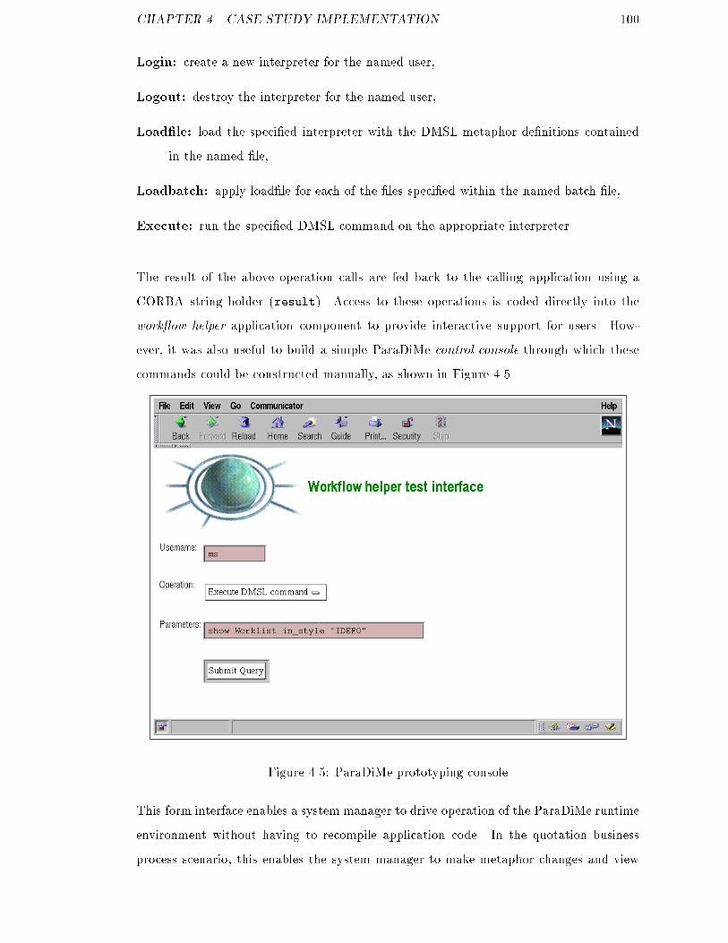
CHAPTER 4. CASE STUDY IMPLEMENTATION 100Login: create a new interpreter for the named user,Logout: destroy the interpreter for the named user,Load�le: load the speci�ed interpreter with the DMSL metaphor de�nitions containedin the named �le,Loadbatch: apply load�le for each of the �les speci�ed within the named batch �le,Execute: run the speci�ed DMSL command on the appropriate interpreter.The result of the above operation calls are fed back to the calling application using aCORBA string holder (result). Access to these operations is coded directly into thework ow helper application component to provide interactive support for users. How-ever, it was also useful to build a simple ParaDiMe control console through which thesecommands could be constructed manually, as shown in Figure 4.5.
Figure 4.5: ParaDiMe prototyping consoleThis form interface enables a system manager to drive operation of the ParaDiMe runtimeenvironment without having to recompile application code. In the quotation businessprocess scenario, this enables the system manager to make metaphor changes and view
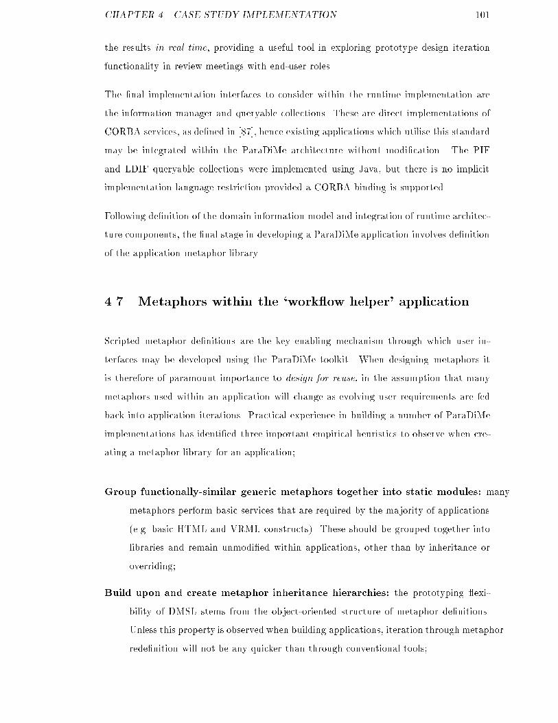
CHAPTER 4. CASE STUDY IMPLEMENTATION 101the results in real time, providing a useful tool in exploring prototype design iterationfunctionality in review meetings with end-user roles.The �nal implementation interfaces to consider within the runtime implementation arethe information manager and queryable collections. These are direct implementations ofCORBA services, as de�ned in [87], hence existing applications which utilise this standardmay be integrated within the ParaDiMe architecture without modi�cation. The PIFand LDIF queryable collections were implemented using Java, but there is no implicitimplementation language restriction provided a CORBA binding is supported.Following de�nition of the domain information model and integration of runtime architec-ture components, the �nal stage in developing a ParaDiMe application involves de�nitionof the application metaphor library.4.7 Metaphors within the `work ow helper' applicationScripted metaphor de�nitions are the key enabling mechanism through which user in-terfaces may be developed using the ParaDiMe toolkit. When designing metaphors itis therefore of paramount importance to design for reuse, in the assumption that manymetaphors used within an application will change as evolving user requirements are fedback into application iterations. Practical experience in building a number of ParaDiMeimplementations has identi�ed three important empirical heuristics to observe when cre-ating a metaphor library for an application;Group functionally-similar generic metaphors together into static modules: manymetaphors perform basic services that are required by the majority of applications(e.g. basic HTML and VRML constructs). These should be grouped together intolibraries and remain unmodi�ed within applications, other than by inheritance oroverriding;Build upon and create metaphor inheritance hierarchies: the prototyping exi-bility of DMSL stems from the object-oriented structure of metaphor de�nitions.Unless this property is observed when building applications, iteration through metaphorrede�nition will not be any quicker than through conventional tools;
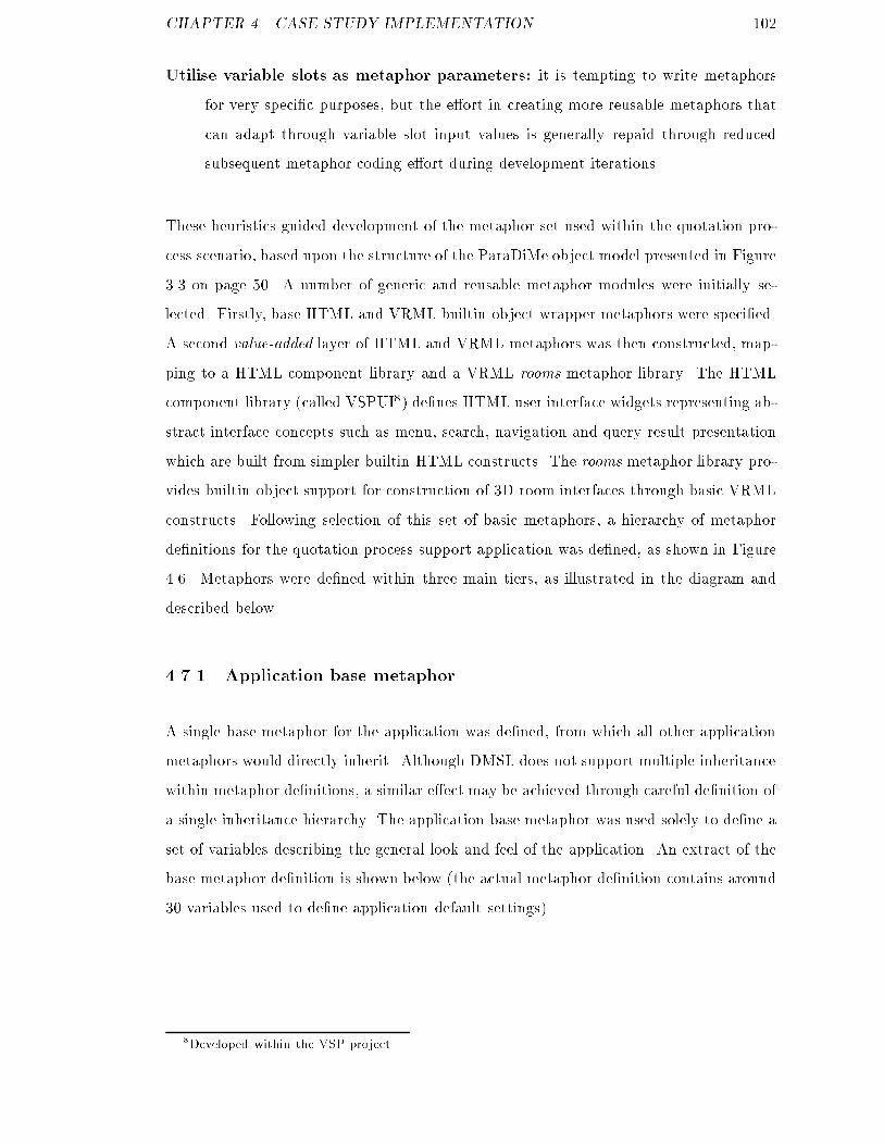
CHAPTER 4. CASE STUDY IMPLEMENTATION 102Utilise variable slots as metaphor parameters: it is tempting to write metaphorsfor very speci�c purposes, but the e�ort in creating more reusable metaphors thatcan adapt through variable slot input values is generally repaid through reducedsubsequent metaphor coding e�ort during development iterations.These heuristics guided development of the metaphor set used within the quotation pro-cess scenario, based upon the structure of the ParaDiMe object model presented in Figure3.3 on page 50. A number of generic and reusable metaphor modules were initially se-lected. Firstly, base HTML and VRML builtin object wrapper metaphors were speci�ed.A second value-added layer of HTML and VRML metaphors was then constructed, map-ping to a HTML component library and a VRML rooms metaphor library. The HTMLcomponent library (called VSPUI8) de�nes HTML user interface widgets representing ab-stract interface concepts such as menu, search, navigation and query result presentationwhich are built from simpler builtin HTML constructs. The rooms metaphor library pro-vides builtin object support for construction of 3D room interfaces through basic VRMLconstructs. Following selection of this set of basic metaphors, a hierarchy of metaphorde�nitions for the quotation process support application was de�ned, as shown in Figure4.6. Metaphors were de�ned within three main tiers, as illustrated in the diagram anddescribed below.4.7.1 Application base metaphorA single base metaphor for the application was de�ned, from which all other applicationmetaphors would directly inherit. Although DMSL does not support multiple inheritancewithin metaphor de�nitions, a similar e�ect may be achieved through careful de�nition ofa single inheritance hierarchy. The application base metaphor was used solely to de�ne aset of variables describing the general look and feel of the application. An extract of thebase metaphor de�nition is shown below (the actual metaphor de�nition contains around30 variables used to de�ne application default settings).8Developed within the VSP project.
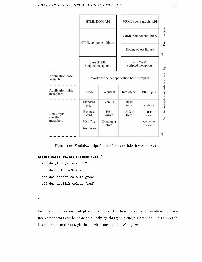
CHAPTER 4. CASE STUDY IMPLEMENTATION 103HTML DOM API VRML scene-graph API
HTML component library
VRML component library
Base HTMLscripted metaphors
Base VRMLscripted metaphors
Rooms object library
Bui
ltin
obje
cts
Scri
pted
met
apho
r in
heri
tanc
e hi
erar
chy
Workflow helper application base metaphor
Person
Standardpage
Businesscard
3D office
Groupware
Worklist
Vanilla
Helpwizard
Documentstore
Info object
Readonly
Updateform
PIF object
PIF activity
IDEF0 view
Structureview
Application-base metaphor
Application-wide metaphors
Role / stylespecificmetaphorsFigure 4.6: `Work ow helper' metaphors and inheritance hierarchydefine QuoteAppBase extends Null {add def_font_size = "+1"add def_colour="black"add def_header_colour="green"add def_hotlink_colour="red"...}Because all application metaphors inherit from this base class, the look-and-feel of inter-face components can be changed quickly by changing a single metaphor. This approachis similar to the use of style sheets with conventional Web pages.

CHAPTER 4. CASE STUDY IMPLEMENTATION 1044.7.2 Information object metaphorsA set of information object metaphors were created using the VSPUI metaphor set, whichprovided forms-style interfaces to the simple workitem representations de�ned within thequotation business process. Two duplicate sets of information object metaphors werecreated. The �rst set provided a readonly presentational displays for an informationobject, whilst the second set enabled information object updates to be implemented viathe ParaDiMe form interaction subsystem. Objectclass and Style metaphor contextdescriptors were used to enable appropriate automated metaphor selection at runtime.For example, the following DMSL fragment extract shows the context description forthe metaphor to enable forms editing of a network design proxy object. An example ofthe HTML form generated from this metaphor, along with a summary of the runtimeprocesses through which the form is handled, is presented in Figure 4.7.define EditND extends QuoteAppBase {used_to_display infondObject within Viewer in_style 'editing'...}4.7.3 Activity metaphorsTwo sets of metaphors were de�ned that enable HTML-based navigation of PIF processde�nition in di�erent presentational styles. Firstly, a compact representation providingan indented list of task names through which a user could drill-down was created (basedaround a style called StructureStyle). A more sophisticated process navigation metaphorset was then de�ned to meet the needs of the account manager and process designerroles, who require a more detailed end-to-end view of the business process. A commongraphical modelling language for business processes is IDEF0 [82], based upon the SADTmodelling technique. This describes processes as sequences of activities which may them-selves comprise subordinate activities. An IDEF0 style for presentation of PIF activityobjects was constructed, through which the account manager or process designer couldnavigate the quotation business process model. The metaphors make extensive use ofDMSL information access constructs to follow relational links within through the processde�nition stored as a set of objects within the information manager component. Hence,
CHAPTER 4. CASE STUDY IMPLEMENTATION 105for each task within the quotation process, the metaphor can also display other usefulinformation (e.g. what information objects are created or updated by the activity, whoperforms the activity and who indirectly collaborates during it's performance). Variableslot parameters act as switches in selecting a level-of-detail for the interface enabling, forinstance, a process view just showing who is responsible for performing each stage. Thestructure of the DMSL de�nitions used to create the IDEF0 metaphor set are shown inFigure 4.8. Sample HTML output for the StructureStyle and IDEF0 style metaphors ispresented in Figure 4.9.The PIF activity metaphors were designed to operate with arbitrary process descriptions(de�ned using the simpli�ed activity, component and successor constructs introducedearlier). Hence changing business process characteristics, as signi�ed during applicationiterations by submission of a modi�ed PIF �le, does not require metaphor recoding. Themetaphors were also designed to enable their incremental re�nement upon subsequentaddition of further PIF constructs as shown in Figure 4.2.4.7.4 Worklist metaphorsWithin the case study scenario it was also desirable to provide mechanisms facilitatingexploration of alternative representations of worklists. As introduced earlier, worklistsprovide work ow users with `to-do' lists of jobs for completion, usually providing somesummary information about the job status e.g. the initiator, the type of activity andrelated tasks or information artefacts. It was identi�ed that di�erent roles within thequotation process could require di�erent worklist representations. For example, a legaladvisor might be called into the process quotation on a relatively infrequent basis, hencecould bene�t from the addition of extra context help within the worklist interface. Thenetwork design team need to collaborate over a set of design documents in performingtheir contribution to the process and could therefore bene�t from a document manage-ment facility integrated within the work ow client interface. To demonstrate metaphorextension and specialisation through subclassing, a basic vanilla worklist metaphor wasde�ned which provides a conventional work ow client user interface (Figure 4.10). Twoextended versions of the basic worklist metaphor were then derived by subclassing thevanilla metaphor de�nition. In the �rst specialisation, a context sensitive help featurewas added. The second specialisation links the worklist to a shared document repository,

CHAPTER 4. CASE STUDY IMPLEMENTATION 106which could be used by process participants to share information artefacts.The goal in developing the worklist metaphors was to demonstrate the application ofthe model-based architecture towards rapid prototyping, in which a number of similarinterfaces to the same functional application component may be explored quickly withend users.4.7.5 Person object and groupware execution metaphorsThe �nal set of metaphors which were built within the work ow helper implementationwere used to demonstrate access to collaborative working tools via the groupware con-trol subsystem within the model-based toolkit. Within the case study context, there areseveral conceivable points at which participant roles need to collaborate in order to per-form activities. For example, the network designer and legal advisor collaborate during adesign review task to ensure the proposed network infrastructure does not contravene rel-evant legislation. In tracking jobs through the process chain, the account manager needsto communicate with the sta� assigned to the job in order to ascertain progress. Therequirements for collaboration were demonstrated within the work ow helper applicationby extending the business process description language (PIF) to associate communicationrequirements with activity de�nitions. A PIF partially-shared view (PSV) module wasused to create a new PIF relation, called assists, which models the situation where a per-son helps during an activity but is not directly responsible for performing that activity.This was de�ned through extension of the PIF core performs relation;(define-frame ASSISTS:own-slots((Name "WfhPsv.ASSISTS")(Subclass-of PERFORMS)(Documentation "Agent collaborates on activity")))This enabled simple collaboration requirements to be described within PIF �les, usedto present business process models to the work ow helper application. Two styles ofmetaphors were used to demonstrate groupware access within the toolkit environment,as shown in Figure 4.11. Firstly, a basic HTML metaphor was built to operate upon in-
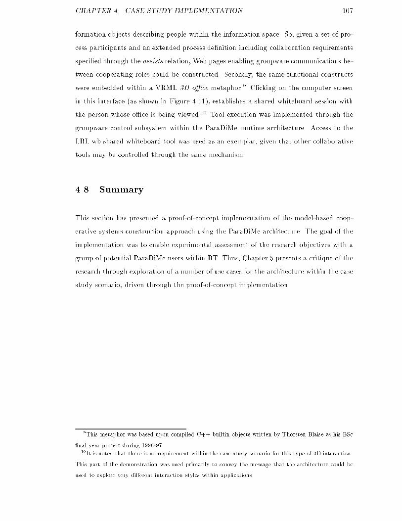
CHAPTER 4. CASE STUDY IMPLEMENTATION 107formation objects describing people within the information space. So, given a set of pro-cess participants and an extended process de�nition including collaboration requirementsspeci�ed through the assists relation, Web pages enabling groupware communications be-tween cooperating roles could be constructed. Secondly, the same functional constructswere embedded within a VRML 3D o�ce metaphor.9 Clicking on the computer screenin this interface (as shown in Figure 4.11), establishes a shared whiteboard session withthe person whose o�ce is being viewed.10 Tool execution was implemented through thegroupware control subsystem within the ParaDiMe runtime architecture. Access to theLBL wb shared whiteboard tool was used as an exemplar, given that other collaborativetools may be controlled through the same mechanism.4.8 SummaryThis section has presented a proof-of-concept implementation of the model-based coop-erative systems construction approach using the ParaDiMe architecture. The goal of theimplementation was to enable experimental assessment of the research objectives with agroup of potential ParaDiMe users within BT. Thus, Chapter 5 presents a critique of theresearch through exploration of a number of use cases for the architecture within the casestudy scenario, driven through the proof-of-concept implementation.9This metaphor was based upon compiled C++ builtin objects written by Thorsten Blaise as his BSc�nal year project during 1996-97.10It is noted that there is no requirement within the case study scenario for this type of 3D interaction.This part of the demonstration was used primarily to convey the message that the architecture could beused to explore very di�erent interaction styles within applications.
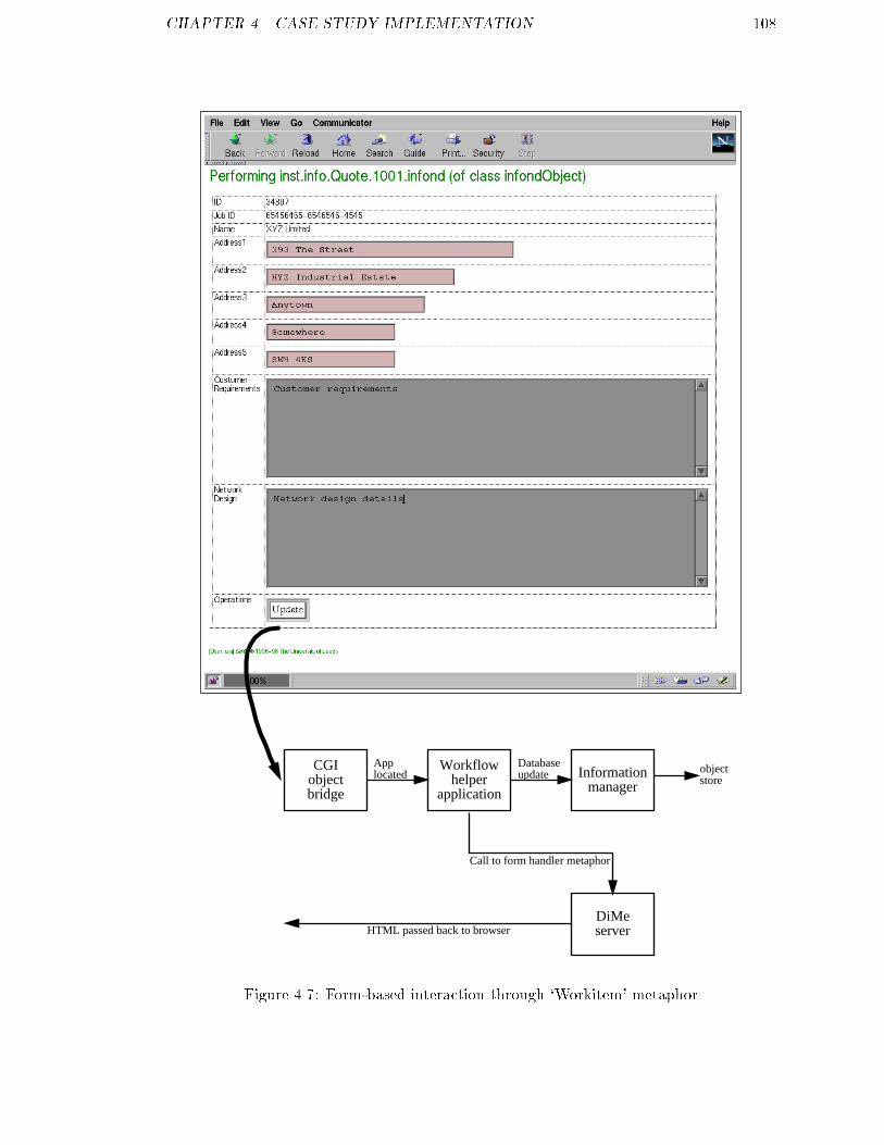
CHAPTER 4. CASE STUDY IMPLEMENTATION 108
CGIobjectbridge
Workflowhelper
application
Informationmanager
DiMeserver
Call to form handler metaphor
Databaseupdate
HTML passed back to browser
objectstore
Applocated
Figure 4.7: Form-based interaction through `Workitem' metaphor

CHAPTER 4. CASE STUDY IMPLEMENTATION 109define IDEFpadcols extends PGroup { add depth = 1 add width = "100"
set page to_contain { add cs as HTTableNewColumn(width=$width) when ($depth !=0); add ce as HTTableNewColumnEnd when ($depth != 0); add ip as IDEFpadcols(depth = $depth + -1) when ($depth != 0); }}
define IDEFnewcolumn extends PGroup { add fednameref="root" add cellwidth = "100" add cellfontsize = "-1" add cellfontcolor = "black" add cellbgcolor = "white" add cellfont = $def_font add cellalign = "center" add cellvalign = "top"
set page to_contain { add cs as HTTableNewColumn(width=$cellwidth, bgcolor=$cellbgcolor, align=$cellalign, valign=$cellvalign);
add fs as HTLiteralText(text = "<font face=" + $cellfont + " size=" + $cellfontsize + " color=" + $cellfontcolor + ">");}}
define IDEFcolumnend extends PGroup { set page to_contain { add fe as HTLiteralText(text = "</font>"); add ce as HTTableNewColumnEnd;}}
define IDEFinfocol extends IDEFnewcolumn { add creates = "" add updates = "" add performs = "" add helpers = "" add createsc = "red" add updatesc = "green" add performsc = "yellow" add helpersc = "blue"
set cellbgcolor = "" set cellalign = "right"
set page to_contain { add ct as HTText(text=$creates, colour=$createsc); ...}}
define IDEFtaskcol extends IDEFnewcolumn { add taskname="" add fedref=""
set cellfontsize = "+1" set cellfontcolor = "blue"
set page to_contain { add ct as HTLiteralText(text= "<br>" + $taskname + "<br><br>");}}
define IDEFlevel extends PGroup { add depth = 0
set page to_contain { add tr as HTTableRow(align="center"); add ip as IDEFpadcols(depth=$depth); add ic as IDEFinfocol(creates=Data.linkcreates); add ie as IDEFcolumnend; add tc as IDEFtaskcol(taskname=Data.fedname, fedref=Data.fedname); add te as IDEFcolumnend; add re as HTTableRowEnd; add s as set_of(Data->"Linksuccessor") using IDEFlevel(depth = $depth + 1) if ($search_result_count!=0);}}
define IDEFactivity extends PGroup { used_to_display PIFACTIVITY within Viewer in_style "IDEF"
set page to_contain { add ts as PTableStart(border=0, cellspacing="10", cellpadding="10", align="center"); add s as set_of(Data->"Linkfirstc") using IDEFlevel if ($search_result_count!=0); add te as PTableEnd; }}
IDEFactivity leaf metaphor providing HTML tabular IDEF0
style representations of PIF business process specifications
Recursive metaphor whichcreates a single row of the
IDEF diagram
Represent a particularPIF task as a table cell
Associate information witha task cell, provided by a
a metaphor parameter, extended from the IDEFnewcolumn
metaphor definition
Finish a column
Base class for diagram columns,describing layout and basic
colour scheme, inheriting someproperties from the application
base metaphor
Creates blank columns tocreate a top-left to
bottom-right IDEF styletabular layout
Metaphor subclassing
Metaphor callFigure 4.8: DMSL de�nitions used to create the IDEF0 metaphor set
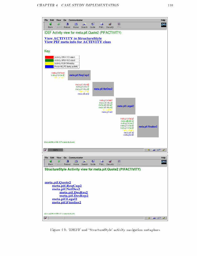
CHAPTER 4. CASE STUDY IMPLEMENTATION 110
Figure 4.9: `IDEF0' and `StructureStyle' activity navigation metaphors
CHAPTER 4. CASE STUDY IMPLEMENTATION 111
Figure 4.10: `Vanilla,' `Wizard' and `Reading-room' worklist metaphors

CHAPTER 4. CASE STUDY IMPLEMENTATION 112
groupwaretool
execution
Figure 4.11: Groupware control metaphor using the LBL wb whiteboard tool

Chapter 5Critique5.1 Assessment methodsThe research presented in this thesis proposes a model-based systems development ap-proach for integrated internet CSCW systems. The approach was realised through thedesign of the ParaDiMe system architecture, as presented in Chapter 3. A proof-of-concept CSCW application was then created according to the model-based approach,using the ParaDiMe architecture. In measuring the extent to which the research meetsthe objectives set out in Chapter 1, a number of methods were employed to assess theapproach, architecture and implementation;� Software demonstration and feedback session,� Follow-up interviews with potential users,� Assessment of feasibility within VWS,� Assessment from a software engineering perspective.As described in Chapter 4, the proof-of-concept work ow helper application was con-structed using the ParaDiMe architecture. The work ow helper was designed to demon-strate the salient features of the model-based systems development approach in supportingparticipants of a network design business process. An important element of the researchassessment was to demonstrate the work ow helper to a potential user community and113
CHAPTER 5. CRITIQUE 114gain feedback. A group of potential BT users of the work ow helper agreed to attenda presentation on the approach, followed by a demonstration of the work ow helperapplication.1 Although unaware of the speci�c details of the model-based approach, at-tendees were familiar with the network design business process scenario and the broadobjectives of the research. The presentation, which lasted approximately an hour, at-tempted to describe the motivation for the research and introduce the key architecturalconcepts that would subsequently be demonstrated. A number of usage scenarios forthe proof-of-concept ParaDiMe implementation were introduced in the presentation, assummarised in Section 5.2. These scenarios (based upon the case study network servicesquotation process) were used to provide a storyboard for the software demonstration. Theobjective was to help position the work within a familiar telecommunications context andfocus feedback towards the speci�c research objectives. Following the presentation, thekey features of the work ow helper application were demonstrated to the audience viathe usage scenarios described in Section 5.2. Informal feedback was received during andafter the demonstration, and points were written down in note form. These notes aresummarised in Section 5.3.Following the demonstration of the architecture implementation to a group audience atBT Laboratories, six sta� agreed to participate in longer one-to-one interviews to providemore detailed feedback on the research. As well as providing useful assessment of theapproach, the interviewees made a number of useful practical suggestions that drovefurther development iterations of the architecture and the work ow helper demonstration.Because of the broad nature of the demonstration and the varying backgrounds of theinterviewees, a formal questionnaire-based technique was rejected in favour of informallystructured interviewing. Notes were taken during interviewing and then transcribed into areport [110]. Whilst not rigidly adhering to a prede�ned script, the interviews attemptedto elicit answers around the following topics;� perception of the research approach as potential users,� feedback on the work ow helper implementation,� relevance of the approach to BT applications.1The research was jointly supervised by BT Laboratories, but to promote objectivity, the assessmentprocess was carried out in conjunction with sta� who were not directly involved with the PhD project.
CHAPTER 5. CRITIQUE 115The interviews were conducted over a week long visit to BT premises. The interviewslasted between �fteen and forty-�ve minutes, with an average duration of around half anhour. After conducting the set of interviews, similar comments from each interviewee werecollated. Feedback was varied, re ecting the range of backgrounds and perspectives ofthe interviewees. However, the salient results could informally be grouped under severalheadings, as summarised in Section 5.4.In addition to obtaining feedback on the research from the software demonstration andfollow-up interviews with potential users, an informal assessment of the relevance of thework to system builders within the Virtual Working Systems Group was conducted. Theresults of this assessment, carried out via informal conversations with VWS sta�, is sum-marised in Section 5.5. Finally, the research was critically assessed in comparison torelevant existing software engineering approaches towards system prototyping and main-tenance, as presented in Section 5.6. The remainder of this chapter is structured as shownbelow.Section 5.2 describes system usage scenarios for services quotation business process,which were used to drive the practical demonstration;Section 5.3 summarises the feedback obtained during and after the software demonstra-tion;Section 5.4 summarises the results of interviews with potential users of model-basedtools within BT, following demonstration of the model-based architecture;Section 5.5 summarises the results of informal assessment of the research within theVWS group at Leeds;Section 5.6 analyses the relative success of the model-based approach developed withinthis thesis in comparison to existing approaches, methods and guidelines for proto-typing and evolutionary maintenance.

CHAPTER 5. CRITIQUE 1165.2 Demonstration scenariosThe software demonstration consisted of four usage scenarios, presented in terms of thedata services provision business process described in Chapter 4;21. basic iterative user interface customisation,2. creation of a new business process support application,3. exploratory prototyping of user interface requirements,4. evolutionary change in business process characteristics.All the use cases, as described below, assume the existence of the model-based architectureimplementation comprising reusable CSCW services, appropriate libraries of general userinterface components and the necessary runtime architecture. The use cases were basedupon the stakeholder roles identi�ed for the quotation scenario; a process designer, enduser representative and system manager. During demonstration, the implementation wasdriven by an operator performing the system manager role, using the prototyping console(shown in Figure 4.5). The stories around which the use cases were demonstrated aresummarised below;Basic user interface customisationThe work ow helper application is supporting participants of the network services quota-tion process. Currently, all users interact with the system via a vanilla work ow worklistuser interface. However, the account manager is unfamiliar with the work ow environ-ment and asks the end-user representative if the interface could be made easier to use.The end-user representative, account manager and system manager meet and examine thecurrent worklist interface features. The account manager suggests changes to the helpfeature on the worklist interface. The system manager locates a `help metaphor' com-ponent from the user interace repository, inserts this into the account manager worklistinterface using the architecture, immediately showing the enhanced interface to the users.(Visual results for this use case are shown in Figure 4.10 on page 111).2The assistance of Paul Kearney (of BT) is acknowledged in developing these use cases.
CHAPTER 5. CRITIQUE 117Creation of a new business process support applicationThe process designer is required to put in place a new business process within his businessunit. The new process (data network design) is similar to an existing process currentlysupported by the work ow helper application within the department. Hence, the processdesigner would like to reuse several elements of this existing support infrastructure withinthe new application. The process designer discusses the process requirements with thesystem manager, and provides de�nitions of the new business process as PIF and LDIF�les. The process designer then explains the model descriptions in detail to the systemmanager, who identi�es basic requirements for information, coordination and collabora-tion services. Required runtime architecture components are selected and populated withthe models provided by the process designer. A set of generic user interface componentsare located within the metaphor library and used to build a quick demonstration of theapplication. The end-user roles (network designer, legal advisor and account manager)are identi�ed and their requirements analysed in conjunction with the end-user represen-tative. Application-wide metaphors for the support environment (worklists, workitemsetc.) are then specialised for each end-user role using the basic technique demonstratedin the �rst use case.Exploratory prototyping of user interface requirementsThe account manager has been using the work ow helper environment for a period oftime, but is generally unhappy with the features it provides to assist him in keepingcustomers up-to-date with the progress of their quotations. He arranges a meeting withthe end-user representative and system manager. The account manager explains that herequires the ability to check job progress and communicate with other sta� assigned tocomponent tasks, but doesn't know how these features might best be provided within thework ow helper application. The system manager notes these general requirements andarranges to meet the account manager again in a few days. During this time, the systemmanager uses the model-based architecture to build and modify a number of similar userinterface metaphors that enable navigation through business processes in di�erent styles.A reusable groupware subsystem metaphor is also added to the prototype interface set, todemonstrate communications features. The system manager, account manager and end-

CHAPTER 5. CRITIQUE 118user representative meet again, and the system manager demonstrates several alternativeinterfaces to the account manager. The account manager chooses the version which mostclosely meets his requirements, which is then moved into the production system by thesystem manager. (Visual results for this use case are shown in Figures 4.9 and 4.11 onpages 110 and 112).Evolutionary change in business process characteristicsSupport of the data services quotation process through the work ow helper has beenoperational for some time, and now needs to be modi�ed. Five types of evolutionarychanges may be envisaged,1. change in application-wide user requirementse.g. all interfaces must adopt new corporate style guidelines;2. change in role-speci�c user requirementse.g. a specialised workitem interface for the legal advisor role;3. change in personal user requirementse.g. account manager Alan White requires a context help feature;4. change in business process modele.g. the network design activity is split into research and reporting phases;5. change in application information modele.g. a new attribute is added to the network design information object.Cases 1{3 can be demonstrated through reference to the previous use cases. Changes inbusiness process characteristics (as indicated by changes in process de�nition or applica-tion information models) may be considered through a single use case;3The process designer navigates the quotation provision process de�nition using the struc-tural and IDEF activity views within the work ow helper application. Following instruc-tion from business unit management, the process designer is asked to further divide the3Because PIF business process de�nitions are treated in the same way as any other information sourceswithin the ParaDiMe information manager subsystem.
CHAPTER 5. CRITIQUE 119network design task into two explicit subordinate phases, a research activity and a report-ing activity. The process designer uses a modelling tool to modify the process de�nition,which is then exported from the tool into PIF and passed to the system manager. Thesystem manager loads the application with the updated model at an appropriate point,and codes new workitem metaphors for the participants a�ected by the new subtasks. Noother changes are necessary because the application-wide metaphors are designed to copewith evolving process and information models.5.3 Feedback from the demonstrationsDemonstrations of the model-based approach contextualised by the above use cases weregenerally well-received. The proof-of-concept architecture implementation was successfulin enacting the four use cases, thereby providing a basic existence proof of the approachtaken within this research. The demonstrations were conducted at BT premises using theWWW to access a remote application server based at the CVWE in Leeds. This workedadequately, but poor network latency adversely a�ected perception of the architecture.Interface generation performance was not a primary consideration during implementationand hence, when compounded by a slow client-sever network connection, interface gener-ation was particularly slow (taking around 10 seconds round-trip time for generation ofa simple HTML page, for example).The use cases, and the ways in which it was envisioned that a model-based architecturecould support them, were seen as realistic (although necessarily simpli�ed for researchpurposes) and of bene�t to process-oriented system builders. The application of the ar-chitecture in supporting rapid exploration of design ideas with end-users was seen asparticularly useful. However, several people were less convinced of the approach in sup-porting process evolution, positing that most current major WFMS implementations aremodel-driven and as such can `evolve' unaided already. This is true of course, but indefence it was argued that the work ow helper is a speci�c demonstration of a generalsystems development approach. Hence, the fact that it can exchange information and co-evolve with commercial WFMS implementations is a bene�t of the model-based approach,not a duplication of development e�ort.
CHAPTER 5. CRITIQUE 1205.4 Results of follow-up interviews with potential usersSynergies with the IBS approachA primary advantage of the model-based approach was seen as the ability to quicklyintegrate services, providing the role of value-added middleware within a dynamic enter-prise. A number of users remarked that it was useful in `bringing people further into thebusiness process environment,' enabling at least partial reconciliation of process-orientedand ad hoc collaboration approaches to supporting users within CSCW scenarios. Us-ing the model-based approach within Agent-based Work ow architectures was seen asfeasible, particularly in providing exible user interfaces that enhance human interactionand collaboration within the work ow environment. Several interviewees asked whetherthe architecture could be used to provide information visualisation services within theABW architecture e.g. creating 3D representations of inter-agent negotiation. Informalexperimentation within the model-based architecture following these questions concludedthat such services could be provided, but would require development of a specialist set ofbuiltin objects.Linkage with commercial systemsThe adoption of industry standards for integrating services was viewed as important to thecredibility of the research approach working within a large enterprise. The use of X.500(directory services) and CORBA query services (information management) was seen asuseful, in that a wide range of other enterprise information sources could be rapidly in-tegrated using similar approaches. The assumptions made about access to build-timeand runtime WFMS appeared to be sensible within the approach, although it was notedthat signi�cant further development would be required to bring the implementation toproduction functionality. One perceived advantage of the distributed systems architec-ture, through which the model-based approach is realised, was that it enables computingpower to be leveraged at a wider range of points within the enterprise. Many existingwork ow users have terminal-type equipment whereas others have sophisticated PCs andworkstations. The model-based approach could enable basic interfaces to be provided toterminal users and more sophisticated interfaces to be provided to users of more powerful
CHAPTER 5. CRITIQUE 121clients, with no distinction made at the applications level.Prototyping versus evolutionThe utility of the model-based approach in enabling rapid exploration of design choicesbetween scenario stakeholders was noted. A key advantage of the approach was viewedas the fast turnaround time on iterations through model modi�cation, rather than codemodi�cation and recompilation. It was envisaged that this could enable some degree ofreal-time prototyping to take place with users, improving upon existing techniques inwhich there is a necessary delay of hours/days between prototype iterations. The IBS re-search emphasis is towards dynamic evolution of production systems, rather than iterativeprototype-based construction of new systems. It was noted that, because the implemen-tation system components were themselves of a prototypical nature, it was di�cult toassess claims about the applicability of the approach within production environments.However, it was further noted that there was a good informal indication from the ex-perimental architecture that such claims could be true, but substantiation would requiredevelopment of the architecture implementation to more robust production-quality level.It was felt that the model-based approach could, in principle, support both prototypingof new applications and evolution of production systems at the modelling layer. That is,the role of prototyping would be to quickly derive a good user interface model, but theapplication components driven through this model during prototyping would ultimatelybe discarded. The model would then serve as a speci�cation from which a productionquality system could then be engineered, either using conventional development processesor a robust version of the model-based architecture.Information integration and abstractionThe element of the implementation which attracted most criticism during demonstra-tion and interviews was the application information model. The initial position takenduring development of the model-based approach was that all information sources couldbe mapped into a simple E-R graph representation. In retrospect, this view proved tobe somewhat naive and several consequential problems were encountered during imple-mentation of the work ow helper application. The most serious of these problems was
CHAPTER 5. CRITIQUE 122that information abstraction issues were not addressed adequately. For instance, withinthe work ow helper, several abstract tiers of information may be identi�ed e.g. busi-ness process class (quotation processes), business process (network services quotation),process instance (quotation job 1003), process instance status (job 1003 awaiting legaladvice). The work ow helper application attempted to cover several of these tiers, butthe separation between layers become confused during implementation e.g. process meta-descriptive information and instance information was incorrectly mixed within PIF �les.Although these criticisms were towards the work ow helper application, not the model-based development approach, they did serve to identify that the domain informationmodel was much more complex than originally thought. Whilst the basic architecturalmechanisms proposed for information management within the research appeared to bevalid, the methodological emphasis upon information modelling was underestimated.User-initiated adaptivitySeveral interviewees noted that the research approach seemed restrictively focused uponsupporting system-initiated user interface adaptivity. For example, all the use cases for theproof-of-concept implementation demonstration assumed that an expert operator wouldbe available to make applications changes within the architecture. It was asked if, throughappropriate use of the information manager and metaphor de�nitions, support for user-initiated interface adaptivity might be supported. In response, a quick experiment wasconstructed using the architecture in which a simple user pro�le was stored as a persistentinformation object. A metaphor was then written that enabled menu-based updating ofthis object using the form interaction subsystem. This enabled a user to, for example,select a default help level from a menu and for this to be kept and used over severalsessions. The basic mechanisms of the architecture appeared adequate in supportingpersistent user pro�les to enable user-initiated interface adaptivity. It was noted that, asa future work package, it would be useful to package up these features into a reusablemodule as they would be useful in many scenarios. One interviewee also stated that thisbasic mechanism could feasibly be used to provide location-driven interface adaptivity,a manner similar to home/remote locations in mobile telephony. This would enabledi�erent pro�les to be created for di�erent computing clients from which a user connectsto the application server (e.g. desktop PC, laptop, dial-up access, PDA). Providing that
CHAPTER 5. CRITIQUE 123metaphor sets were created for each type of client computing device, the pro�le could beused to guide dynamic selection of the appropriate metaphor set at login.Web user interface consistencyThere were a number of questions relating to the use of Web user interface techniquesin supporting multi-user applications. Firstly, it was asked how context switching withinthe Web interface was handled i.e. how the system could cope with a user browsingelsewhere and then returning to the application at some future point. Within the currentproof-of-concept implementation there is no explicit support for session control. Theproblem has, however, been tackled successfully by other researchers developing session-oriented applications within Web infrastructure (e.g. the Stanford KSL ontology editor).When constructing the proof-of-concept implementation it was assumed that, as withsecurity, session control measures would be present in a production environment but didnot warrant explicit research investigation. The question asked was, \given that themodel-based approach supports a service provider in specifying how an artefact should bemanifested at the user interface, yet also supports a service consumer in customising theirinterface to the artefact, is it not likely that semantic inconsistencies will be introducede.g. a feature deemed critical by the service provider is demoted or even ignored by theconsumer?"4 This problem was not explicitly addressed within the research approach, inthat it was assumed that the application designer would be responsible for ensuring thatsuch inconsistencies do not arise.However, it was accepted that in supporting interface customisation for both `produc-ers' and `consumers', there was more chance of problems occurring. There appears tobe no simple solution to this problem. However, some support for component mainte-nance could be provided within the model-based architecture; as a well-de�ned set ofmetaphor de�nitions for an application forms an inheritance hierarchy, it was suggestedthat a token with the same semantics as final in (e.g.) Java could be used within theadd construct to ensure that a component metaphor was not rede�ned or overridden insubclassed metaphors. Whilst this would not guarantee consistency, it would go some waytowards supporting preservation of important interface features. Finally, the use of the4This is an example of what is referred to as a feature-interaction problem within the telecommunica-tions community.

CHAPTER 5. CRITIQUE 124model-based approach to provide an interface abstraction layer was identi�ed as being ofbene�t. Large enterprises must typically support a heterogeneous set of client hardwareand software, over which the model-based approach could provide an abstract user in-terface generation layer. The phenomenal pace at which Web technologies are advancingwas also noted as a reason for adopting a model-based interface generation approach.It was felt that the approach would be a useful structured approach in bringing newWeb technologies on-stream whilst still supporting existing baselines across an enterprisecomputing environment.5.5 Assessment within the VWS groupThe majority of the research work reported within this thesis was conducted at Leeds,within the CVWE. Most of the research assessment was conducted with BT however, inorder to obtain more objective results. Although of a less formal nature, assessment wasalso carried out within the CVWE at Leeds in order to measure the potential bene�tof the research to development of VWS solutions. As the project neared completion,a number of discussions were held with members of the engineering team within VWSLtd. (the commercial exploitation arm of the CVWE) to elicit feedback on the researchapproach. The comments provided during these discussions are summarised as follows.The main application for ParaDiMe, and hence the research approach, within VWS wasviewed as supporting rapid generation of customised VWS solutions for customers. Al-though most existing VWS implementations integrate a wide range of core services, severalclients have expressed interest in acquiring a VWS system that is tailored to their spe-ci�c requirements. It was felt that ParaDiMe could help bring together core services intocustomised VWS clones in a rapid yet controlled manner. A customer would be able toselect required services, perhaps through a special demonstration environment, and thenParaDiMe would assist in the generation of a VWS supporting the required features. Thereduced maintenance costs associated with the model-based approach were also thoughtto be of signi�cant bene�t with respect to cloning VWS services. It was felt that, withouta uni�ed development and maintenance approach, supporting a heterogeneous base ofVWS implementations would be extremely di�cult.
CHAPTER 5. CRITIQUE 125A further bene�t of the ParaDiMe approach, noted by a VWS engineer, was in supportinga spectrum of Web clients using an abstract interface layer. The VWS engineering teamsupport a large number of users using a variety of client computing platforms and Webbrowsing software to interact with implementations. A number of inconsistencies havebeen observed between di�erent versions of browsers and between platforms, meaningthat it becomes di�cult to guarantee usability levels without adopting a low baseline.It was envisaged that a practical role for ParaDiMe within VWS solutions would be insupporting heterogeneous browsers and platforms through specialised metaphor sets.The feedback on the model-based approach from VWS was generally positive. However,it was noted that it would be unwise to adopt ParaDiMe as a core component of the VWSsoftware architecture unless it was developed to commercial product quality.5.6 Assessment from a software engineering perspectiveThe research reported within this thesis has investigated a model-based approach towardsiterative construction and evolution of integrated internet CSCW applications. The broadhypothesis under consideration is that a model-based approach can decrease cycle timesduring iterative prototyping and maintenance activities. Construction and demonstrationof a prototypical application through a toolkit supporting the model-based approachprovided useful feedback on the research. In addition, it is bene�cial to consider the valueof the approach in comparison to existing software engineering guidelines and methods.It was initially assumed that the model-based approach was equally applicable to proto-typing and evolutionary systems development. As the research progressed, it became ap-parent that this assumption was somewhat misconceived. The subtle di�erences betweenprototyping and iterative development of production systems were not fully understoodduring the early phases of the work, in that prototyping was compared incorrectly toRapid Applications Development (RAD) [70]. The goal of prototyping is to improve re-quirements elicitation in order to derive a more accurate speci�cation which can then beused to drive development. In contrast, RAD attempts to deliver a complete productionquality system as quickly as possible Prototyping may, of course, be used within a RADcycle but it is not essential and prototype code may often be abandoned after it has servedit's requirements engineering purpose [78]. There are good reasons for not propagating
CHAPTER 5. CRITIQUE 126code developed through prototyping into production systems e.g. it may not be possible toretro-�t important system services ignored during prototyping and the system structurewill typically degrade through ad hoc modi�cation during prototyping [107]. In analysingthe approach developed within this research, it is thus useful to consider its applicationtowards prototyping and evolutionary development of production systems separately;PrototypingThe model-based approach proposed in this thesis was validated through experimentalimplementation of the architecture, described in Chapters 3 and 4. Investigative empha-sis within the research was placed upon the use of the architecture within prototypingphases of software development projects [111]. In [15], Boar de�nes a number of candidacyfactors by which an assessment of the extent to which an application is amenable to pro-totyping may be made; application area, application complexity, customer characteristicsand project characteristics. As a application domain, CSCW is not a good candidate forprototyping because of the baseline level of system complexity required to demonstratebasic cooperative working functionality. The model-based approach promotes rapid pro-totype implementation through reuse of basic building-block system components however,helping to overcome much application complexity. With the architecture available to sys-tem developers, all competency criteria for prototyping de�ned by Boar are satis�ed; ifcomplexity is reduced to an adequate level through a model-based approach, CSCW ap-plications become good candidates for prototyping because of their high levels of userinteractivity. Customer and project characteristics may respectively be met through will-ingness to participate in evaluation and provision of the architecture environment withinthe system development method. As a prototyping tool, the model-based architecturedeveloped using ParaDiMe appears to mirror Somerville's four heuristics for reducingprototype cycle times [107];Use a high-level language: Although system-oriented, DMSL may be viewed as a highlevel executable speci�cation of user interaction;Relax non-functional requirements: The current architecture implementation doesnot address performance, security or other non-functional issues (although thesemay be required in a production quality architecture implementation);
CHAPTER 5. CRITIQUE 127Ignore error conditions: Error-handling within the current architecture has not beenfully developed|it is assumed that models used to drive the architecture are correct;Reduce reliability and quality: Reliability and quality within the architecture are de-pendent directly on the quality of component service implementations.Of course, the fact that the current architecture implementation exhibits these propertiesis in uenced by the compressed timescale over which it itself was developed. Whilstidentifying that the architecture is appropriate in prototyping Web-based cooperativesystems, this does not imply that the approach is hence not appropriate in developmentof production systems.Evolutionary development and maintenance of production systemsIt is well known that software engineering based upon modular reusable software compo-nents ultimately improves product reliability and quality [57]. This was a central motiva-tion in applying such an approach to development of internet-based cooperative systems.The approach developed within this thesis is not intended to facilitate a seamless tran-sition from prototyping through to production system development and maintenance.Rather, the approach appears to be useful during prototyping and, given productionquality architectural components, the same approach could o�er several advantages inthe ongoing evolution of production systems.Maintenance is of major concern for software builders, accounting on average for somesixty-percent of product lifetime cost [97]. The object oriented nature of the model-basedarchitecture developed within this research helps reduce maintenance e�ort as systemchanges are required. Firstly, the emphasis placed upon reuse of existing service com-ponents reduces the target-area in which errors may occur (assuming that the reusablecomponents are themselves error free). Secondly, the side e�ects of maintenance activi-ties [90] are reduced through the highly object-oriented nature of the architecture. Theseproperties were observed experimentally during construction of the work ow helper proofof concept implementation. ParaDiMe forces developers to delineate user interface, infor-mation model and application-speci�c code. It was initially thought that as requirementschanged, signi�cant modi�cation to application-speci�c code would be required. However,

CHAPTER 5. CRITIQUE 128after a number of corrective and perfective maintenance iterations, the compiled code por-tion of the work ow helper remained fairly static. The majority of subsequent changescould be a�ected at the modelling layer e.g. the use case which demonstrated evolution ofthe work ow helper application did not require any code changes, rather recon�gurationof the information, process and user interface models used to drive the application. Themodel-based interface would thus seem useful during maintenance activities, provided thatthe basic system architectural components were designed to cope with recon�guration atthe model de�nition level. That is, implementation correctness following modelling recon-�guration could be guaranteed. A major aim within this research project was to developarchitecture components that are resilient to model-changes. However, it was noted thatdevelopment of components with intrinsic reuse and change resilience properties requiresmuch more e�ort than tactical solutions. For example, it was informally noted during de-velopment of the work ow helper that creation of a reusable metaphor took (on average)over twice as long as development of a similar hard-wired example. However, this cost isa one-o� cost and should be recouped through reduced maintenance costs.Although it is noted that prototyping and evolutionary maintenance are di�erent prob-lems, the model-based approach can be bene�cial during both phases of the softwarelifecycle as described above. Furthermore, there appear to be advantages in linking thetwo phases through the approach. Prototyping using ParaDiMe derives a model re ect-ing user requirements which can then directly be used to engineer a production system(possibly re-implementing services but retaining the bulk of the derived model). Thus,there is less scope for requirements to be mis-translated or lost within the implementa-tion phase. A further interesting linkage between the use of ParaDiMe during prototypingand maintenance phases is analogous to spare-part replacement in hardware maintenance.When faults occur in harware systems, it is often less expensive to replace a defectivesubsystem rather than repair a speci�c fault e.g. replacement of a defective computermemory module. A spare parts strategy could also be used to reduce maintenance e�ortwithin software projects [36]. Prototyping often generates a number of candidate featureimplementations from which one is �nally selected. The model-based approach directlysupports hot-swapping of components following change requests and could, thereby, fea-sibly be used to rapidly integrate replacement modules. However, the caveat to the spareparts strategy (as noted by Pressman [97]) is that there is a tendency for the same mistakesto be made within independent implementations of the same module.

Chapter 6Conclusions and future work6.1 ConclusionsThe research reported in this thesis has been concerned with structured development tech-niques for integrated CSCW applications that are delivered via internet infrastructure.The research investigated issues surrounding architectural support for CSCW applica-tions, with an emphasis towards service reuse and integration (Chapter 2). An internetCSCW system development approach was proposed which integrates reusable servicesand application speci�c code through a modelling language which speci�es user interac-tion with functional components (Chapter 3). The perceived advantage of this approachis that it enables faster prototype iteration and structured system maintenance. Theseclaims were explored through construction of a proof-of-concept implementation of an ap-plication based upon the ParaDiMe architecture (Chapter 4). The research approach wasprimarily assessed through demonstration of the architecture in supporting prototypingand maintenance activities within a work ow helper application (Chapter 5). Within thebroad goal of contributing to the understanding of structured development techniquesfor CSCW applications, three speci�c hypotheses were tested through the research. Inassessing the results of the work, it is thus useful to retrospectively consider each of theseoriginal hypotheses. 129
CHAPTER 6. CONCLUSIONS AND FUTURE WORK 130\To investigate how common requirements in cooperative working scenarios are met byreusable CSCW services and how such services can be brought to together in a structuredmanner which promotes their integration and reuse within a model-based architecture."This objective arose from an informal observation of cooperative working scenarios, whichnoted that requirements for basic CSCW services were often duplicated across applicationsand application domains. Many other researchers have also investigated frameworks forCSCW services of course (e.g. [85, 45, 58]). The investigation reported within this thesisis distinctive as it speci�cally addresses reuse and integration of services within dynamicenterprise environments. A number of CSCW frameworks were surveyed, from whichbasic requirements for coordination, collaboration and information management serviceswere identi�ed. Existing research and development e�orts within these areas were thenconsidered, in order to identify mechanisms that would enable services to be implementedas reusable components within a model-based architecture. This investigation concludedthat many CSCW services can be reused across applications, and proposed a simple lay-ered framework within which integrated applications may be built from component ser-vices. However, it was also concluded that service reuse was often limited by the visibilityof an application programming interface (API) to the service implementation. The inves-tigation also realised that integrated CSCW systems would typically require integrationwith legacy services within large enterprise computing environments. Hence, the investi-gation focused upon mechanisms through which existing software services (e.g. databases,work ow systems) could be integrated within the model-based environment using stan-dard techniques, rather than requiring redevelopment.\To demonstrate and assess the bene�t of a model-based approach towards system devel-opment through rapid prototyping, to test the hypothesis that the approach signi�cantlyreduces prototype development cycle times thereby enabling a higher level of user partici-pation in the design process."The model-based approach proposed within this thesis appears to be highly appropriatein prototyping internet-based integrated CSCW applications. The major barrier that cur-rently prevents such prototyping activities is the necessarily complex structure of thesesystems, which is re ected in the large amount of coding required to demonstrate basicfunctionality using conventional software engineering approaches. The model-based devel-opment approach hides much of this complexity, allowing the reusable building blocks of

CHAPTER 6. CONCLUSIONS AND FUTURE WORK 131cooperative applications to be assembled and recon�gured very quickly during prototyp-ing. Within the case study, it was possible to demonstrate scenarios of use in which realtime system changes were explored with users. This level of iteration cycle time would besigni�cantly more di�cult, if not impossible, to achieve using conventional software engi-neering approaches. In addition to successful demonstration of the model-based approachthrough proof-of-concept implementation, a comparison to established software engineer-ing prototyping guidelines was performed. The comparison revealed that the approachwas consistent with requirements for a good prototyping architecture and, through sim-pli�cation of application complexity, enabled integrated internet CSCW systems to meetprototyping competency criteria whereas they would not do so through traditional ap-proaches.\To demonstrate and assess the bene�t of a model-based approach towards maintenance ofsystems as user requirements evolve within live applications, to test the hypothesis that theapproach reduces the software e�ort required to a�ect changes thereby enabling evolvinguser requirements to be more e�ciently fed back into systems."This hypothesis could not be substantiated, for several reasons. Firstly, in order to re-alistically assess claims about maintenance within production quality systems, one mustcreate such a system and assess it's evolution naturally over time. However, the timeconstraints upon PhD research are such that this level of development and analysis wasinfeasible. Secondly, the approach was investigated through implementation of the archi-tecture to a proof-of-concept level, within which the research approach was embodied. Asthis implementation was itself of prototypical quality, assessment of it's ability to supportproduction systems would be of little value. But this does not invalidate the hypothesis, itserves merely to acknowledge that it was overly ambitious to attempt to test it within thisresearch project. There was however, strong informal evidence to suggest the suitabilityof the model-based approach in supporting evolutionary systems construction and main-tenance. It would certainly be wrong to assert that the approach could seamlessly owfrom prototyping through implementation to maintenance. The well-known characteris-tic of system structure degradation during prototyping was strongly observed during casestudy assessment. Hence, the use of prototype system architecture components withinproduction systems would not be recommended. However, the models used to drive theprototype could serve as useful design speci�cation templates during implementation and

CHAPTER 6. CONCLUSIONS AND FUTURE WORK 132maintenance activities. A production quality implementation of the model-based archi-tecture would also appear to be of bene�t during software maintenance cycles, reducingthe target area for maintenance and reducing system change side-e�ects. However, be-cause of the di�culties stated above, it must be concluded that it was not possible toprovide substantive evidence with which to bolster these claims.Generality of the model-based approachThe model-based approach to development of internet CSCW systems proposed in thisthesis is based upon de�nition of reusable CSCW services and a speci�cation languagewhich describes user interaction with those services within an application context. Atruntime, the speci�cation is used to drive a Web user interface generator that dynami-cally integrates access to required CSCW services. Although the DiMe DMSL scriptinglanguage was selected as the modelling component of the ParaDiMe architecture, themodel-based approach is itself not dependent upon DMSL. That is, DMSL could be re-placed by other modelling representations for use in other contexts. Conceptually, themodelling component of the ParaDiMe architecture requires a frame-based knowledgerepresentation [77]. Object oriented modelling languages would appear to be particularlyappropriate as these map well to the ParaDiMe object model. However, models used byParaDiMe are speci�cally designed to serve as runtime speci�cations used to integratesystem services and generate user interfaces. Although more general HCI conceptualmodelling frameworks (such as TKS [55]) could feasibly drive the ParaDiMe architecture,it appears likely that some model reformulation would be required to map conceptualinteractional requirements onto system interaction mechanisms.6.2 Future workThe research presented in this thesis has investigated basic system architectural mech-anisms through which internet-based cooperative systems may be integrated, built andmaintained. The results appear promising, giving rise to a number of directions withinwhich future research and development activities might progress.
CHAPTER 6. CONCLUSIONS AND FUTURE WORK 1336.2.1 Modelling language and reasoningThe DiMe architecture and DMSL scripting language were chosen as an experimentaldevelopment vehicle within this research and have proved to be useful in exploring theresearch approach. DiMe was designed primarily to solve a pragmatic system developmentproblem; the automated construction of large scale Web sites that integrate informationaccess within HTML and VRML interaction styles. Although it served to inspire thework presented within this thesis, DMSL is beginning to get pushed beyond its intendeduse. As a modelling language, DMSL su�ers from the same problem as HTML in thatit mixes content and structural semantics. The World Wide Web Consortium (W3C)are introducing a variety of technologies to repair this problem, such as style sheets,extensible markup language etc. The Display Metaphor Scripting Language requiressimilar re-design if it is to remain useful. However, it is not actually clear that DMSL isneeded at all.As noted during Chapter 3, in which the system architecture for the model-based ar-chitecture was introduced, DMSL is in essence an object oriented frame language. Anative-code implementation was chosen to maximise interactive server-side user interfacegeneration performance. But for conceptual modelling, a conventional knowledge repre-sentation language may be a more appropriate vehicle through which further work canbe progressed. The main motivation for this statement is that knowledge representationlanguages are generally designed to enable automated reasoning engines to operate overthem. Knowledge-based approaches towards user interface generation are well-established(e.g. See [104] for a survey of intelligent user interface research), and there are severalreasons for adopting such an approach with ParaDiMe. The point of system-initiated in-terface generation within ParaDiMe is the metaphor selector component. This currentlyoperates using a simple multi-attribute decision strategy in which a DMSL command ismatched against a metaphor index listing target object classes, viewer contexts and stylekeywords for each metaphor known to ParaDiMe. Although useful, this mechanism issimplistic in comparison to most model-based interface generators. This was known dur-ing development of ParaDiMe and it has always been the intention to outsource metaphorselection to a more sophisticated architectural component at some point. A declarativeframe-based modelling language to replace DMSL would ease this transition signi�cantly.
CHAPTER 6. CONCLUSIONS AND FUTURE WORK 134Importantly, an AI approach would also widely increase the representational capabilityof DMSL and allow new concepts to be introduced in a uniform manner; as more andmore constructs have been pragmatically added to DMSL it has lost some perspicuityand gained some unnecessary complexity. For example, once an internal model has beenbuilt within ParaDiMe from a DMSL script, subsequently modifying that model with-out reparsing the initial DMSL model can produce unpredictable results. In contrast,knowledge-based systems typically provide excellent built-in support for dynamic asser-tion and retraction of information. There are also good reasons for adopting such anapproach in embracing other future research directions. For example, distributed agentand task-driven interface generation (as described in the following text) would both ben-e�t from a more general knowledge representation language within ParaDiMe.6.2.2 Distributed and agent-based solutionsA major feature of the model-based architecture developed within this work is the supportfor per-user interface customisation through personalised metaphor de�nitions and DMSLinterpreters. ParaDiMe is a client-server environment in which interfaces are generatedat server-side and passed over the network to thin Web clients as target language streams(e.g. HTML or VRML). This approach was adequate for this research in demonstrating themodel-based approach for a small set of users, but does not scale well for more ambitiousapplications.The proof-of-concept research implementation was built using the CORBA distributedobject architecture which eased the scalability problem signi�cantly. DMSL interpretersare allocated dynamically by the runtime ParaDiMe user interface generator as indepen-dent CORBA objects. With appropriate server management functionality (as providedin major ORB implementations), these objects may be launched over a pool of machinesproviding support for distributed load-balancing.A more ambitious area for future research and development work is to leverage the in-creasing power of Web client machines, by moving towards client-side interface generationtechniques. The current CORBA implementation of ParaDiMe provides an excellent start-ing point for this research, especially given the integration of the Visigenics ORB withinthe popular Netscape Communicator browser. Some initial experiments have achieved
CHAPTER 6. CONCLUSIONS AND FUTURE WORK 135promising results in investigating client-side approaches. Notably, Gareth Bottomleyproduced a working Java applet implementation of a small subset1 of DMSL as his �nalyear undergraduate project [16]. This work used a Java version of PCCTS (as used inthe major ParaDiMe implementation) and connected the tree-walker to a VRML externalapplication interface (EAI) running within an applet. This enabled simpli�ed DMSL con-structs to be dynamically downloaded via a network connection and be applied directly tothe VRML model running within the browser. A client-side interface generation approachis the logical next step forward for the model-based interface generation technique (andhence ParaDiMe), providing two key bene�ts;Firstly, it will enable richer interaction modalities (such as the next generation of Internetinteractive virtual reality standards) to be provided more e�ciently than through conven-tional server-side techniques. For example, representation of a detailed o�ce scene mayrequire several megabytes of VRML and component models, textures etc. This must begenerated and packaged on the server, sent over the (increasingly bandwidth-constrained)Internet and parsed into the client VRML browser. The client-side model-based approachwould be to cache a library of basic reusable interface components on the client and use acontrolling applet (or other code) to synthesise interfaces on-the- y, in response to DMSLcommands sent from the application server. This would provide massive bandwidth re-duction over VRML transmission, even with scene-compression techniques.The second advantage of moving towards a client-side approach is in more e�ectivelysupporting individual user interaction preferences. Mechanisms currently exist withinParaDiMe to support user initiated interface adaption through user pro�les stored inthe information space and appropriate references to these pro�les within metaphors. Forexample, a pro�le might maintain a user-skill-level attribute through which the user mightbe classi�ed as a novice or expert This information may then be read into ParaDiMethrough metaphors and used to guide metaphor selection e.g. by dynamic assignment ofthe style metaphor context descriptor. However, this mechanism is somewhat inelegantand di�cult to maintain in practise. A better solution would be to investigate ParaDiMeagents, which would manage presentation services on a per-user basis. It is envisionedthat the agents would be tightly integrated within the client browser, with access to theinternal document model API enabling dynamic interface generation capabilities. The1Five constructs.

CHAPTER 6. CONCLUSIONS AND FUTURE WORK 136user interface customisation services provided through this approach could potentiallyintegrate with other personal-assistant agent functions on client machines, cf. [67].6.2.3 Task and interaction modellingThe `models' that drive the model-based approach to cooperative systems developmentinvestigated within this research are user interface component models, rather like widgetsin conventional user interface toolkits. These widgets encapsulate form and function intosome useful interface abstraction e.g. a telephone metaphor that establishes an audioconferencing call upon selection within a scene. The ParaDiMe model-based interfacegenerator provides the basic representational and operational mechanisms for buildinguser interfaces to multi-user cooperative working systems. The research reported withinthis thesis has attempted to raise the level at which these systems are created closer to theuser domain. However, there is still a wide gap between scenario requirements modellingand system implementation.A future research direction for the model-based techniques developed within this project(and in related work within the CVWE) would be to investigate interface generation forcooperative systems from task-oriented conceptual models, extending existing theoriesand methods such as Task Knowledge Structures (TKS) [55], which has proved useful inrapid prototyping of systems through task models [56]. The objective in this researchwould be to derive a formal task-interaction model of cooperative work describing users,the shared work context to be provided by the system, and the interactions which mustbe supported within that work context (e.g. user-to-system, user-to-artefact within thesystem, user-to-user mediated by the system). The ambitious research goal would be toinvestigate user interface speci�cation or generation directly from such a model (using anarchitecture such as ParaDiMe), although it is currently not clear that such an approach iseither feasible or desirable. A potentially more tractable objective would be to use a task-oriented CSCW model to identify commonly occurring tasks and interactions; constructreusable system services and interfaces that embody these requirements; and then usea model-based interface generation toolkit to create integrated cooperative applicationsthrough rapid integration of these basic cooperative working building blocks.
CHAPTER 6. CONCLUSIONS AND FUTURE WORK 1376.2.4 Visual system construction toolsAlthough the model-based approach developed within this project attempts to furtherinvolve end-users within design and prototyping of cooperative systems, operation of thecurrent user interface generation architecture (built using ParaDiMe) requires a relativelyhigh level of technical expertise to accomplish simple tasks. Although this is perhaps morea development exercise rather than research direction, there is a need to derive visual toolsthat support the functionality of DMSL whilst hiding the language behind a graphicalintegrated development environment (IDE). Products such as Microsoft's Visual InterDevsuite have signi�cantly simpli�ed the task of creating Web-based information systems,and a similar approach seems highly appropriate for involving non-technical stakeholdersdirectly in the model-based systems development process. A starting-point in movingtowards a visual toolkit would be to augment the functionality of a standard Web designtool (e.g. Microsoft FrontPage), with a toolbox of cooperative working widgets which couldbe `drag-and-dropped' into interfaces as required. A control function (perhaps similar tothe publish feature in FrontPage) could then generate out a set of runtime architecturecomponents that would implement the functionality speci�ed within the visual design tool.This work would take a signi�cant amount of time and resources to implement successfully,but moving at least some way towards a visual toolkit is essential in investigating the wideruse of model-based design techniques.6.2.5 Richer 3D interaction stylesThis research has been developed over a four year period between 1994 and 1998, duringwhich time internet technologies have advanced greatly. One area that has attracted in-creasing interest during the project is internet virtual reality technologies, such as VRML.The research reported within this thesis has not attempted to contribute towards under-standing in this area. An existing VRML interface generation module was adopted froma related CVWE research e�ort and was used primarily to demonstrate the utility of amodel-based approach in seamlessly supporting both 2D and 3D interaction modalities.The decision not to pursue VRML interface generation as research investigation withinthis PhD was made primarily because of the poor support for scene interactivity in theVRML implementations available during the project (i.e. VRML 1.0). Whilst it was pos-
CHAPTER 6. CONCLUSIONS AND FUTURE WORK 138sible to generate VRML o�ces for example, it was not possible to populate or animatethem with real world interactive objects e.g. people. Hence, whilst 3D presentational in-terfaces looked attractive and helped to contextualise system services for neophyte users,their actual contribution to the functional operation of system was of negligible bene�tor even detrimental to usability.Internet VR technology is advancing at a fast pace however, largely fuelled by the in- uential entertainment and leisure markets. Technologies such as VRML 2.0, Java 3Dand more recently Microsoft Chrome are moving towards an Internet VR interaction in-frastructure. The bene�ts of ParaDiMe are readily apparent within 3D interaction styles,where there are currently very few products supporting automated construction of interac-tive Internet-based VR worlds. Fewer still, if any, enable dynamic integration of CSCWservices within these environments. Hence, there is potential research in investigatingmodel-based construction of cooperative working environments using the emerging inter-active Internet VR technologies. The emphasis in this investigation would be in task-basedinteraction modelling as described earlier, di�erentiating the research from existing worksuch as that of Benford et al. [11]. It would be particularly interesting, given ParaDiMe's exible interface generation capabilities, to study the integration of support for 2D and3D interaction modes within such environments (e.g. switching from a 3D style used tobrowse a virtual library shelf to a 2D style used to interact with a particular document).6.3 Closing remarksThis thesis takes a software engineering perspective upon supporting cooperative workwithin dynamic internet environments. Software engineering methodologies provide well-established modelling and design abstractions for the functional and behavioural char-acteristics of such systems. However, direct representational and tool support for HCI-informed systems engineering is at best peripheral and at worst non-existent within cur-rent software engineering methods (See e.g. [59]).In the same way that the patterns work of Gamma et al codi�ed and encapsulated best-practise knowledge to promote reuse of object-oriented software concepts [32], there is areal need for HCI design patterns to be fed into mainstream software engineering. This�rstly requires that HCI principles be embraced within widely-used software engineering
CHAPTER 6. CONCLUSIONS AND FUTURE WORK 139methods; not just making a token appearance in non-functional requirements or styleguides. Secondly, there is a requirement for these patterns to be embodied within CASEtools so that software engineers and usability engineers may share a common interlinguathat more formally injects HCI knowledge through into implementations.The opinion advocated through this thesis is that the World Wide Web will be a pri-mary factor in narrowing the gap between HCI and software engineering. As client-serverimplementations, the user interfaces of Web information systems are necessarily sepa-rated from functional components. Unlike conventional client-server systems however,the HTML user interface delivery mechanism is ubiquitous and externally adaptable bynon-programmers. As Gayna Williams of Microsoft's usability group notes, HTML inter-faces are now becoming important design speci�cation and prototyping tools that enableparticipatory design iterations to occur extremely late in the product development pro-cess [118]. The ultimate goal of the research presented within this thesis is to movetowards CASE tools and methods which directly support this prevailing compressed formof software product lifecycle.
Bibliography[1] George Almasi, Anca Suvaiala, Ion Muslea, Calin Cascaval, Ted Davis, and V. Ja-gannathan. Web�: a technology to make information available on the Web. In Pro-ceedings of the Fourth IEEE Workshop on Enabling Technology: Infrastructure forCollaborative Enterprises: WET-ICE '95, Concurrent Engineering Research Centre,West Virginia University, 1995.[2] American National Standards Institute, Standard X3.135-1992. Database Language-SQL, January 1993.[3] Architecture Projects Management Ltd. The ANSA Reference Manual, 1989.[4] Lowell Arthur. Rapid evolutionary development : requirements, prototyping andsoftware creation. Wiley, New York, 1992.[5] A. B�acker and U. Busbach. DocMan: A document management system for cooper-ation support. In Proceedings of the 29th Hawaii International Conference on theSystem Sciences, volume 3, pages 82{91, Maui, January 1996.[6] L. Bannon and K. Schmidt. Issues of supporting organisational context in CSCWsystems. COMIC Project Deliverable 1.1, Ocober 1993.[7] Liam Bannon and Kjeld Schmidt. CSCW: Four characters in search of a context. InJ. M. Bowers and S. D. Benford, editors, Studies in Computer Supported CooperativeWork. Elsevier Science Publishers, North Holland, 1991.[8] M. Barbuceanu and M. Fox. The architecture of an agent based infrastructure foragile manufacturing. Technical report, Enterprise Integration Laboratory, Univer-sity of Toronto, 1995. 140
BIBLIOGRAPHY 141[9] M. Barbuceanu andM. Fox. The information agent: Building intelligent informationinfrastructures for enterprise integration. Technical report, Enterprise IntegrationLaboratory, University of Toronto, 1995.[10] C. Batini, M. Lenzerini, and S. B. Navathe. A comparative analysis of methodologiesfor database schema integration. ACM Computing Surveys, 18:323{365, 1986.[11] Steve Benford, John Bowers, Lennart Fahlen, John Mariani, and Tom Rodden.Supporting cooperative work in virtual environments. The Computer Journal,37(8):653{668, 1994.[12] Steve Benford, Adrian Bullock, Neil Cook, Paul Harvey, Rob Ingram, and Ok-kiLee. From rooms to cyberspace: Models of interaction in large virtual computerspaces. In Interacting with Computers. Butterworth-Heinmann, 1993.[13] R. Bentley, T. Horstmann, K.Sikkel, and J. Trevor. Supporting collaborative infor-mation sharing with the World Wide Web: The BCSCW shared workspace system.In Proceedings of the Fourth International World Wide Web Conference, Boston,December 1995.[14] Gordon Blair and Tom Rodden. The impact of CSCW on Open Distributed Pro-cessing. In De Meer et al. [23], pages 143{153.[15] B. Boar. Application Prototyping. Wiley-Interscience, 1984.[16] Gareth Bottomley. A client-side Java VRML generation language. BSc �nal yearproject dissertation, School of Computer Studies, University of Leeds, UK, 1998.[17] Adrian Bullock. Visualising organisations. In John Bowers, editor, A Concep-tual Framework for Describing Organisations, chapter 10, pages 229{240. COMICProject Deliverable D1.2, October 1994.[18] R. G. G. Cattell, editor. The Object Database Standard: ODMG-93 v1.2. MorganKaufmann, 1994.[19] P. P. Chen. The entity relationship model{towards a uni�ed view of data. ACMTransactions on Database Systems, 1(1), March 1976.[20] M. F. Costabile, D. Malerba, M. Hemmje, and A. Paradiso. Building metaphors forsupporting user interaction with multimedia databases. In Proceedings of 4th IFIP

BIBLIOGRAPHY 1422.6 Working Conference on Visual DataBase Systems (VDB 4), L'Aqulia, Italy,May 1998.[21] T. Crowley, P. Milazzo, E. Baker, H. Forsdick, and R. Tomlinson. MMConf: Aninfrastructure for building shared multimedia applications. In Proceedings of CSCW'90, Los Angeles, October 7{10 1990.[22] S. Das, K. Kochut, J. Miller, A. Sheth, and D. Worah. ORBWork: A reliabledistributed CORBA-based work ow enactment system for METEOR2. Technicalreport, LSDIS Laboratory, University of Georgia, 1997.[23] J. De Meer, V. Heymer, and R. Roth, editors. Proceedings of the IFIP TC6/WG6.4International Workshop in Open Distributed Processing, Berlin, Germany, October1991.[24] P. M. Dew, C. M. Leigh, R. S. Drew, D. T. Morris, and J. M. Curson. Collab-orative working systems to support user interaction within a virtual science park.Information Services and Use, 15:213{228, 1995.[25] Richard Drew. Integrated Information Directory Services to Support the InnovationProcess. PhD thesis, School of Computer Studies, University of Leeds, UK, June1997.[26] Rae Earnshaw and John Vince, editors. The Internet in 3D: Information, Imagesand Interaction. Academic Press, 1997.[27] C. A. Ellis, S. J. Gibbs, and G. L. Rein. Groupware: some issues and experiences.Communications of the ACM, 34(1), January 1991.[28] S. Elrod, R. Bruce, R. Gold, F. Halasz, W. Janssen, D. Lee, K. McCall, E. Pedersen,K. Pier, J. Tang, and B. Walsh. Liveboard: a large interactive display to supportgroup meetings, presentations and remote collaboration. In Proceedings of CHI '92,pages 599{607. ACM Press, 1992.[29] D. Engelbart and H. Lehtman. Working together. In Byte, pages 245{252. CMPMedia, December 1988.[30] K. Fischer, J. P. M�uller, I. Heimig, and A. W. Scheer. Intelligent agents in virtualenterprises. In Proceedings of the First International Conference on the Practical
BIBLIOGRAPHY 143Applications of Intelligent Agents and Multi-Agent Technology (PAAM '96), pages205{223, 1996.[31] Fernando Flores, Michael Graves, Brad Hart�eld, and Terry Winograd. Computersystems and the design of organizational interaction. ACM Transactions on O�ceInformation Systems, 6(2):153{172, April 1988.[32] Erich Gamma, Richard Helm, Ralph Johnson, and John Vlissides. Design Patterns:Elements of Reusable Object-Oriented Software. Addison-Wesley, 1994.[33] M. Genesereth and R. Fikes. Knowledge interchange format: Version 3.0 refer-ence manual. Technical report, Computer Science Department, Stanford University,1992.[34] J. Giarratano and G. Riley. Expert Systems: Principles and Programming. Inter-national Thomson Publishing, 1994.[35] S. J. Gibbs. LIZA: An extensible groupware toolkit. In Proceedings of the ACMSIGCHI Conference on Human Factors in Computing Systems, Austin, Texas, 1989.ACM Press.[36] T. Gilb. Software spare parts. In G. Parikh, editor, Techniques of Program andSystem Maintenance. Winthrop Publishers, 1981.[37] S. L. Goldman. 21st Century Manufacturing Enterprise Strategy: An Industry-LedView. Iococca Institute, Lehigh University, 1991.[38] S. L. Goldman, R. N. Nagel, and K. Preiss. Agile Competitors and Virtual Organi-zations. Van Nostrand Reinhold, January 1995.[39] P. M. D. Gray, A. Preece, N. J. Fiddian, W. A. Gray, T. J. M. Bench-Capon,M. J. R. Shave, N. Azarmi, M. E. Wiegand, M. Ashwell, M. Beer, Z. Cui, B. Diaz,S. M. Embury, K. Hui, A. C. Jones, D. M. Jones, G. J. L. Kemp, E. W. Lawson,K. Lunn, P. Marti, J. Shao, and P. R. S. Visser. KRAFT: Knowledge fusion fromdistributed databases and knowledge bases, database and expert system applica-tions. In Database and Expert System Applications (DEXA' 97), Toulouse, 1997.[40] Saul Greenberg. Personizable groupware: Accommodating individual roles andgroup di�erences. In L. Bannon, M. Robinson, and K. Schmidt, editors, Proceed-
BIBLIOGRAPHY 144ings of the Second European Conference on Computer Supported Cooperative Work(ECSCW '91). Kluwer Academic Publishers, 1991.[41] I. Grief, editor. Computer Supported Cooperative Work: A book of readings. MorganKaufmann, 1988.[42] Shishir Gundavaram. Web Gateways: Increasing the Power of the Web. WorldWide Web Journal, 2(2):191{202, Spring 1997.[43] P. Gust. Shared X: X in a distributed group work environment. In Proceedings ofthe Second Annual X Conference, MIT, January 1988.[44] S. Harrison and S. Minneman. The media space: A research project into the use ofvideo as a design medium. In Proceedings of Conference on Participatory Design,pages 51{58, Seattle, WA, March 1990.[45] P. Hennessy, P. Harvey, and H. Smith. Support for enterprise modelling in CSCW.Technical report, NEXOR Ltd., 1994.[46] David Hollingsworth. The work ow reference model. Work ow Management Coali-tion, Document TC00-1003 Issue 1.1, November 1994.[47] M. Huhns, N. Jacobs, T. Ksiezyk, W. M. Shen, M. Singh, and C. Tomlinson. En-terprise information modeling and model integration in Carnot. In Petrie [95].[48] Neil Hunter. Secure, User Centred Conferencing for Virtual Working Systems. PhDthesis, School of Computer Studies, University of Leeds, UK, December 1997.[49] International Business Machines Corporation, Vienna, Austria. FlowMark Work owModeling, 1994. Release 1.1.[50] ISO/IEC 10646. Extensible Markup Language (XML). Standard speci�cation, 1997.[51] ITU and ISO/IEC 9594-1. X.500{The Directory: Information Technology, OpenSystems Interconnection. Standard speci�cation, 1992.[52] Y. Jayachandra, editor. Re-engineering the Networked Enterprise. McGraw-Hill,New York, 1993.[53] N. R. Jennings, P. Faratin, M. J. Johnson, T. J. Norman, P. O'Brien, and M. E.Wiegand. Agent-based business process management. International Journal ofCooperative Information Systems, 1996.
BIBLIOGRAPHY 145[54] R. Johansen. Leading Business Teams. Addison-Wesley, Reading, MA, 1991.[55] P. Johnson and H. Johnson. Task Knowledge Structures: psychological basis andintegration into system design. Acta Psychologica, 78:3{26, 1991.[56] P. Johnson, H. Johnson, and S. Wilson. Rapid prototyping of user interfaces drivenby task models. In J. M. Carroll, editor, Scenario-based design for human computerinteraction. John Wiley and Sons, Inc., 1995.[57] T. C. Jones. Reusability in programming: a survey of the state of the art. IEEETransactions on Software Engineering, 10(5):488{494, September 1984.[58] T. Kalin, H. Lubich, and J. Rugelj. A proposal for the architectural model forCSCW. Technical report, Co-Tech Project (COST 14) WG3, 1990.[59] Elizabeth Kemp and Chris Phillips. Extending support for user interface design inobject-oriented software engineering methods. In May et al. [71].[60] G. Lako� and M. Johnson. Metaphors We Live By. University of Chicago Press,1980.[61] Kenneth Lantz. The prototyping methodology. Prentice-Hall, Englewood Cli�s, N.J,1986.[62] Peter Lazar and Peter Holfelder. Web database connectivity with scripting lan-guages. World Wide Web Journal, 2(2):203{219, Spring 1997.[63] J. Lee, M. Gruninger, Y. Jin, T. Malone, A. Tate, and G. Yost. The PIF process in-terchange format and framework. Technical report, PIF Working Group, Universityof Hawaii, May 1996. Version 1.1.[64] J. Lee and T. Malone. Partially shared views: A scheme for communicating amongstgroups that use di�erent type hierarchies. ACM Transactions on O�ce InformationSystems, 8(1):1{26, 1990.[65] W. Litwin and A. Abdellatif. Multidatabase interoperability. IEEE Computer,19(12):10{18, December 1986.[66] J. D. Mackinlay, G. Robertson, and S. Card. Cone trees: Animated 3D visualizationsof hierarchical information. In Proceedings of the ACM SIGCHI '91 Conference onHuman Factors in Computing Systems, pages 189{194, 1991.

BIBLIOGRAPHY 146[67] P. Maes. Agents that reduce work and information overload. Communications ofthe ACM, 37(7):31{40, July 1994.[68] T. W. Malone and K. Crowston. Toward an interdisciplinary theory of coordination.Technical Report 120, Center for Coordination Science, MIT Sloan School, 1991.[69] Marilyn Mantei. Observation of executives using a computer supported meetingenvironment. In Decision Support Systems 5, pages 153{166. Elsevier Science Pub-lishers, North Holland, 1989.[70] James Martin. Rapid Application Development. Macmillan, 1991.[71] Jon May, Jawed Siddiqi, and Julie Wilkinson, editors. Adjunct Proceedings of BCSHuman Computer Interaction '98, She�eld, UK, September 1998.[72] D. McCarthy and S. Sarin. Work ow and transactions in InConcert. Bulletin ofthe Technical Committee on Data Engineering, 16(2), 1993.[73] R. McCool. The common gateway interface. Technical report, NCSA, 1995.[74] R. Medina-Mora, T. Winograd, R. Flores, and F. Flores. The ActionWork owapproach to work ow management technology. In Proceedings of CSCW '92, pages281{288. ACM Press, 1992.[75] P. Merle, C. Gransart, and J. Gei�. CorbaWeb: A WWW and Corba worlds in-tegration. In Second COOTS Workshop on Distributed Object Computing on theInternet, Toronto, June 1996.[76] D. Miers. The use of technology within business process redesign initiatives and thefuture of information systems. In Proceedings of the CCTA Emerging TechnologyShowcase, pages 98{108, London School of Economics, January 4{6 1995.[77] Marvin Minsky. A framework for representing knowledge. In P. Winston, editor,Psychology of Computer Vision. McGraw-Hill, New York, 1975.[78] Ian Mitchell. A CASE Supported Approach to Object-Oriented Rapid Prototyping.PhD thesis, Rapid Prototyping Laboratory, University of Sunderland, UK, 1997.[79] D. T. Morris, G. Lajos, P. M. Dew, R. S. Drew, and D. Willows. DiMe: An objectoriented scripting language for the automatic creation of virtual environments. InProceedings of Eurographics UK Chapter Conference, April 1997.
BIBLIOGRAPHY 147[80] National Industrial Information Infrastructure Protocol Consortium (NIIIPC). NI-IIP Reference Architecture: Concepts and Guidelines, Technical Report NTR95-01Cycle 0, January 1995.[81] National Industrial Information Infrastructure Protocol Consortium (NIIIPC). Taskand Session Objects: Common objects for enabling virtual enterprise resource shar-ing and collaboration, NIIIPC OMGBusiness Objects RFP Response, January 1997.[82] National Institute of Standards and Technology. Integration De�nition for Func-tion Modeling (IDEF0), Federal Information Processing Standards Publication 183,December 1993.[83] National Institute of Standards and Technology. Integration De�nition for Infor-mation Modeling (IDEF1X), Federal Information Processing Standards Publication184, December 1993.[84] National Institute of Standards and Technology. Framework for NII Services, Re-port NISTIR 5478, December 1994.[85] L. Navarro, M. Medina, and T. Rodden. Environment support for cooperativeworking. Technical report, Universitat Polit�ecnica de Catalunya and University ofLancaster Computing Department, 1994.[86] A. Obaidi, R. Drew, and P. M. Dew. Generic approach to agent systems withapplication to adviser project. In Proceedings of the ECSCW '97 Workshop onSocial Agents in Web-based Collaboration, Lancaster, UK, September 1997.[87] Object Management Group. CORBAservices: Common Object Services Speci�ca-tion, OMG Document 97-12-03, November 1997.[88] Object Management Group. The Common Object Request Broker: Architecture andSpeci�cation, OMG Document 97-09-01, Revision 2.1, August 1997.[89] D. Palaniswami, J. Lynch, I. Shevchenko, A. Mattie, and L. Reed-Fourquet. Web-based multi-paradigm work ow automation for e�cient healthcare delivery. In Pro-ceedings of the NSF Workshop on Work ow and Process Automation in InformationSystems: State-of-the-art and Future Directions, July 1996.[90] G. Parikh, editor. Techniques of Program and System Maintenance. Winthrop Pub-lishers, 1981.
BIBLIOGRAPHY 148[91] Terrance Parr. Language Translation Using PCCTS and C++. Automata Publish-ing Company, 1996.[92] Encarna Pastor and Jonny Jager. Architectural framework for CSCW. In Coopera-tion Among Organisations: the potential of Computer Supported Cooperative Work,ESPRIT Research Reports, Project 5660. Springer, 1993.[93] J. F. Patterson, R. D. Hill, S. L. Rohall, and W. S. Meeks. Rendezvous: Anarchitecture for synchronous multi-user applications. In Proceedings of the ACMConference on Computer Supported Cooperative Work (CSCW '90), Los Angeles,1990. ACM Press.[94] Mark Pesce. VRML: Browsing and Building Cyberspace. New Riders, 1995.[95] Charles Petrie, editor. Enterprise Integration Modeling: Proceedings of the FirstInternational Conference. MIT Press, 1992.[96] J. Preece, Y. Rogers, H. Sharp, D. Benyon, S. Holland, and T. Carey. HumanComputer Interaction. Addison-Wesley, 1994.[97] Roger Pressman. Software Engineering: A Practitioner's Approach. McGraw-Hill,2nd edition, 1989.[98] Wolfgang Prinz and Paola Pennelli. Relevance of the X.500 Directory to CSCWApplications. In D. Marca and G. Bock, editors, Groupware: Software for ComputerSupported Cooperative Work, pages 209{225. IEEE Computer Society Press, 1992.[99] Dave Raggett. Client-side scripting and HTML. In Scripting Languages: Automat-ing the Web, World Wide Web Journal, volume 2, pages 29{37. O'Reilly, 1997.[100] Dave Raggett, Arnaud Le Hors, and Ian Jacobs. HTML 4.0 Speci�cation. WorldWide Web Consortium, April 1998. Recommendation REC-html40-19980424.[101] A. S. Rogers and S. Gray. Virtuosi- supporting collaboration in design and manu-facture. In Procedings of Telecom '95 Technology Summit, Geneva, October 1995.[102] S. Rowett, S. Saunders, P. M. Dew, C. M. Leigh, and E. J. Foster. A virtualscience park to support work-based learning. In Proceedings of World Conferenceon Educational Telecommunications, Calgary, Canada, June 1997.
BIBLIOGRAPHY 149[103] James Rumbaugh, Michael Blaha, William Premerlani, Frederick Eddy, andWilliam Lorenson. Object-Oriented Modeling and Design. Prentice-Hall, 1991.[104] M. Schneider-Hufschmidt, T. K�uhme, and U. Malinowski, editors. Adaptive UserInterfaces. Elsevier Science Publishers, 1993.[105] Amit Sheth. Work ow automation: applications technologies and research. SIG-MOD Conference tutorial notes, May 1995.[106] Amit Sheth. From contempory work ow process automation to adaptive and dy-namic work activity coordination and collaboration. Technical report, Large ScaleDistributed Information Systems Lab, University of Georgia, 1997.[107] Ian Somerville. Software Engineering. Addison Wesley, 3rd edition, 1989.[108] Guy Steele. Common LISP: the language. Digital Press, 2nd edition, 1990.[109] M. Ste�k, G. Foster, D. Bobrow, K. Kahn, S. Lanning, and L. Suchman. Beyond thechalkboard: computer support for collaboration and problem solving in meetings.Communications of the ACM, 30(1):32{47, January 1987.[110] M. A. Swaby. Research assessment results: BT interview transcripts. InternalPhD project report, School of Computer Studies, University of Leeds, June 1998.Unpublished manuscript.[111] Michael Swaby, Peter Dew, David Morris, and Gyuri Lajos. System support forrapid prototyping of collaborative internet information systems. In May et al. [71].[112] M. Uschold, M. King, S. Moralee, and Y. Zorgios. The Enterprise Ontology. Tech-nical report, AIAI Enterprise Project, June 1995.[113] F. Vernadat. CIMOSA: Enterprise modelling and enterprise integration using aprocess-based approach. In H. Yoshikawa and J. Goossenaerts, editors, Informa-tion Infrastructure Systems for Manufacturing, volume B-14, pages 65{79. ElsevierScience, North-Holland, 1993.[114] Norman Walsh. An introduction to cascading style sheets. In Advancing HTML:Style and Substance, World Wide Web Journal, volume 2, pages 147{156. O'Reilly,1997.

BIBLIOGRAPHY 150[115] J. Wernecke. The Inventor Mentor: Programming Object Oriented 3D Graphicswith Open Inventor. Addison Wesley Publishing Company, 1994.[116] Gio Wiederhold. Intelligent integration of diverse information. In T. Finin,C. Nichola, and Y. Yesha, editors, First International Conference on Informationand Knowledge Management, Baltimore, November 1992.[117] Gio Wiederhold. Mediators in the architecture of future information systems. IEEEComputer, 25(3):38{49, March 1992.[118] Gayna Williams. Usability process challenges in a Web product cycle. In May et al.[71].[119] D. Woelk and C. Tomlinson. The InfoSleuth project: Intelligent search managementvia semantic agents. In Proceedings of the Second International World Wide WebConference, October 1994.[120] M. J. Wooldridge and N. R. Jennings. Intelligent agents: Theory and practise. TheKnowledge Engineering Review, 10(2):115{152, 1995.[121] World Wide Web Consortium. Document Object Model Speci�cation, TR-WD-DOM-971209 (Working Draft), December 1997.