Abstract
41
Micro-controller Based Function Generator and PC Oscilloscope Mentored by : Dr. Dheeraj Joshi
description
A
Transcript of Abstract

Micro-controller Based Function Generator and PC
Oscilloscope
Mentored by :
Dr. Dheeraj Joshi
Submitted by:-
Akshat Mathur (2k12/EE014)
Anurag Gupta (2k12/EE/027)
Jatin Batra(2k12/EE/064)
ABSTRACTFunction generators and Oscilloscopes are indispensable part of Electrical Engineering and are used in almost all the labs be it Instrumentation, LIC or Control. However, the frustrating part about the oscilloscope and function generators are they are bulky and way too expensive. It is almost impossible for a hobby electronists to own a one. In this project we propose a function generator and a PC Oscilloscope with MATLAB deploying the internal ADC of ATmega328P micro-controller and external R-2R DAC. For the Oscilloscope part of the project, we use a Arduino Development Board to capture the signal values on one of the analog channels and pass them to MATLAB running a script via USB. The MATLAB script plots the data for a desired number of samples. The Oscilloscope thus proposed is capable of measuring signals up to 5kHz and 5 volts on a single channel. The Arduino Development Board uses a R-2R DAC to produce various functions like sine, square, triangle and saw-tooth. Frequencies up to 7kHz and peak-to-peak amplitude of 5 volts can be produced which are more than sufficient for tinkering with electronic circuits. The Oscilloscope and function generator proposed are efficient, compact and inexpensive for their use in electronic circuits. The use of a Micro-controller allows the user to make any number of changes with code to get the desired result. MATLAB being a complete mathematical package allows many further possibilities such as Fast-Fourier Transform, 3D Plot , Signal Processing and thresh-hold marking.


Delhi Technological University, Delhi
Department Of Electrical Engineering
CERTIFICATEThis is to certify that the report entitled, “Steper Motors, Drivers And Their Application In 3D Printer” submitted by Jatin Batra (2k12/EE/064) in partial fulfillment of the requirements for the award of the Bachelor of Technology in Electrical Engineering and submitted to the department of Electrical Engineering of Delhi Technological University, Delhi is authentic record of my own work carried out under my supervision and guidance.
To the best of my knowledge, the matter embodied in the report has not been submitted to any other University/institute for the award of any degree or diploma.
Prof. Madhusudan Singh
HOD, EE Department
DTU,Delhi Signature
Dr. Dheeraj Joshi
EE Department
DTU, Delhi Signature
DEPARTMENT ELECTRICAL ENGINEERING
DELHI TECHNOLOGICAL UNIVERSITY, DELHI
ACKNOWLEDGEMENTI take this opportunity to express my profound gratitude and deep regards to my guide Dr. Dheeraj Joshi, for his exemplary guidance, monitoring and constant encouragement throughout the course of this report. The blessing, help and guidance given by him time to time shall carry me a long way in the journey of life on which I am about to embark. Last but not the least I would like to thank my parents and the broad reprap open source community to bear me.
Jatin Batra
2K12/EE/064
Dept. Of Electrical Engineering
DTU, Delhi

LIST OF FIGURES…
1. Fig1: Insights of a Stepper Motor2. Fig2: Permanent Magnet Stepper Motor3. Fig3: Working of a permanent magnet stepper motor4. Fig4:Methods to increase the resolution of a permanent magnet stepper 5. Fig5: Variable reluctance stepper6. Fig6: Working of a variable reluctance stepper7. Fig7:Methods to increase the resolution of a variable reluctance stepper 8. Fig8:Hybrid Stepper 9. Fig9:Hybrid Rotor 10.Fig10:Working of a hybrid stepper 11.Fig11:Unipolar stepper 12.Fig12:Bipolar Stepper 13.Fig13:Wave Drive 14.Fig14:Full Drive 15.Fig15:Microstepping 16.Fig16: RAMPS17.Fig17: Sanguinololu Board 18.Fig18: Bipolar Stepper 19.Fig19: End Stops
CONTENTS
CERTIFICATE…….......................................................................................................................i
ACKNOWLEDGEMENT………………………………………………………………………………...ii
LIST OF FIGURES………………………………………………………………..iii
CHAPTERS
1. INTRODUCTION…………………………………………..
2. Stepper Motors………………………………………………
2.1Working Principle
2.2Types OF stepper motor
2.3Two-phase stepper motors
2.4Modes Of Stepping
3. 3D Printing………………………………………………….
3.1What is 3D Printing?
3.2Electronics in 3D Printing
3.3Stepper-Motors
3.4End-Stops
4. SIMULATION………………………………………………
4.1Proteus ISIS
4.2Code

Introduction 3D printers especially Home-built 3D Printers are booming. In 2006 there were no
such printers and 8 years later there are tens of thousands. There are currently
hundreds of thousands of people wanting to start their own build waiting for the
right moment to get started. The project that single-handily propelled home-built
3D printers out of nowhere is RepRap. It’s an open-source project meaning that all
the information and design plans you’ll need are available free for all. Building a
3D printer on your own is a huge undertaking.
And one of the toughest part of 3D Printing is electronics in the 3D printing .The
motivation of this project came from over-expensive and cumbersome work
involved in electronics of 3D Printers mainly the stepper motor drivers which can
be as expensive as $200. This calls the need for creating a inexpensive DIY stepper
driver-easy to debug and compatible with almost every open-source firm-wares to
be used in 3D Printing.

Stepper Motors
A stepper motor (or step motor) is a brushless DC electric motor that divides a
full rotation into a number of equal steps. The motor's position can then be
commanded to move and hold at one of these steps without any feedback sensor
(an open-loop controller), as long as the motor is carefully sized to the application.
Working Principle
DC brush motors rotate continuously when voltage is applied to their terminals.
Stepper motors, on the other hand, effectively have multiple "toothed"
electromagnets arranged around a central gear-shaped piece of iron. The
electromagnets are energized by an external control circuit, such as a
microcontroller. To make the motor shaft turn, first, one electromagnet is given
power, which magnetically attracts the gear's teeth. When the gear's teeth are
aligned to the first electromagnet, they are slightly offset from the next
electromagnet. So when the next electromagnet is turned on and the first is turned

off, the gear rotates slightly to align with the next one, and from there the process
is repeated. Each of those rotations is called a "step", with an integer number of
steps making a full rotation. In that way, the motor can be turned by a precise
angle.
Fig1:Insights of Stepper Motor
Types Of Stepper Motors
There are three main types of stepper motors:
Permanent magnet stepper Hybrid synchronous stepper Variable reluctance stepper
Permanent Magnetic Stepper
The rotor and stator poles of a permanent magnet stepper are not teethed. Instead
the rotor have alternative north and south poles parallel to the axis of the rotor
shaft.

Fig2: Permanent Magnet Stepper Motor
When a stator is energized, it develops electromagnetic poles. The magnetic rotor
aligns along the magnetic field of the stator. The other stator is then energized in
the sequence so that the rotor moves and aligns itself to the new magnetic field.
This way energizing the stators in a fixed sequence rotates the stepper motor by
fixed angles.
Fig3:Working of a Permanent Stepper
The resolution of a permanent magnet stepper can be increased by increasing
number of poles in the rotor or increasing the number of phases.

Fig4: Methods to increase resolution of a stepper motor
Variable Reluctance Stepper
The variable reluctance stepper has a toothed non-magnetic soft iron rotor. When
the stator coil is energized the rotor moves to have a minimum gap between the
stator and its teeth

.
Fig5: Variable Reluctance stepper Motor
The teeth of the rotor are designed so that when they are aligned with one stator
they get misaligned with the next stator. Now when the next stator is energized, the
rotor moves to align its teeth with the next stator. This way energizing stators in a
fixed sequence completes the rotation of the step motor.

Fig6: Working of a Variable Reluctance Stepper
The resolution of a variable reluctance stepper can be increased by increasing the
number of teeth in the rotor and by increasing the number of phases.
Fig7: Methods to increase the resolution of a variable reluctance stepper

Hybrid Stepper
A hybrid stepper is a combination of both permanent magnet and the variable
reluctance. It has a magnetic teethed rotor which better guides magnetic flux to
preferred location in the air gap.
Fig8: Hybrid Stepper Motor
The magnetic rotor has two cups. One for north poles and second for the south
poles. The rotor cups are designed so that that the north and south poles arrange in
alternative manner

Fig9: Hybrid Motor Rotor
The Hybrid motor rotates on same principle of energizing the stator coils in a
sequence.
Fig10: Working of a Hybrid Stepper

Two-Phase Stepper Motors
There are two basic winding arrangements for the electromagnetic coils in a two
phase stepper motor: bipolar and unipolar.
Unipolar motors
A unipolar stepper motor has one winding with center tap per phase. Each section
of windings is switched on for each direction of magnetic field. Since in this
arrangement a magnetic pole can be reversed without switching the direction of
current, the commutation circuit can be made very simple (e.g., a single transistor)
for each winding. Typically, given a phase, the center tap of each winding is made
common: giving three leads per phase and six leads for a typical two phase motor.
Often, these two phase commons are internally joined, so the motor has only five
leads.
A micro controller or stepper motor controller can be used to activate the drive
transistors in the right order, and this ease of operation makes unipolar motors
popular with hobbyists; they are probably the cheapest way to get precise angular
movements.

Fig11: Unipolar Stepper Motor
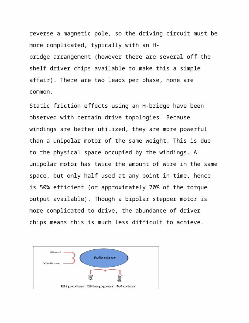
Bipolar motor
Bipolar motors have a single winding per phase. The current in a winding needs to
be reversed in order to reverse a magnetic pole, so the driving circuit must be more
complicated, typically with an H-bridge arrangement (however there are several
off-the-shelf driver chips available to make this a simple affair). There are two
leads per phase, none are common.
Static friction effects using an H-bridge have been observed with certain drive
topologies. Because windings are better utilized, they are more powerful than a
unipolar motor of the same weight. This is due to the physical space occupied by
the windings. A unipolar motor has twice the amount of wire in the same space,
but only half used at any point in time, hence is 50% efficient (or approximately
70% of the torque output available). Though a bipolar stepper motor is more
complicated to drive, the abundance of driver chips means this is much less
difficult to achieve.

Fig 12 : Bipolar Stepper Motor
Modes Of Stepping
A stepper motor is a polyphase AC synchronous motor and it is ideally driven by
sinusoidal current. Various drive techniques have been developed to better
approximate a sinusoidal drive waveform: these are half stepping and
microstepping.
Different drive modes showing coil current on a 4-phase unipolar stepper motor
Wave drive or Full step drive (one phase on)
In this drive method only a single phase is activated at a time. It has the same
number of steps as the full step drive, but the motor will have significantly less
than rated torque. It is rarely used. The animated figure shown above is a wave
drive motor. In the animation, rotor has 25 teeth and it takes 4 steps to rotate by
one teeth position. So there will be 25*4 = 100 steps per full rotation and each step
will be 360/100 = 3.6 degrees.
Fig13 : Wave Drive

Full step drive (two phases on)
This is the usual method for full step driving the motor. Two phases are always on
so the motor will provide its maximum rated torque. As soon as one phase is
turned off, another one is turned on. Wave drive and single phase full step are both
one and the same, with same number of steps but difference in torque.
Fig 14 : Full Drive
Half stepping
When half stepping, the drive alternates between two phases on and a single phase
on. This increases the angular resolution, but the motor also has less torque (approx
70%) at the half step position (where only a single phase is on). This may be
mitigated by increasing the current in the active winding to compensate. The
advantage of half stepping is that the drive electronics need not change to support
it. In animated figure shown above, if we change it to half stepping, then it will
take 8 steps to rotate by 1 teeth position. So there will be 25*8 = 200 steps per full
rotation and each step will be 360/200 = 1.8 degrees. Its angle per step is half of
the full step.
Microstepping
What is commonly referred to as microstepping is often "sine cosine
microstepping" in which the winding current approximates a sinusoidal AC
waveform. Sine cosine microstepping is the most common form, but other

waveforms can be used.Regardless of the waveform used, as the microsteps
become smaller, motor operation becomes smoother, thereby greatly reducing
resonance in any parts the motor may be connected to, as well as the motor itself.
Resolution will be limited by the mechanical striation backlash, and other sources
of error between the motor and the end device. Gear reducers may be used to
increase resolution of positioning. Step size repeatability is an important step
motor feature and a fundamental reason for their use in positioning.
Fig15: Micro-stepping
3D Printing
What Is 3D Printing?
Additive manufacturing or 3D printing is a process of making three dimensional
solid objects from a digital model. 3D printing is achieved using additive
processes, where an object is created by laying down successive layers of material.
3D printing is considered distinct from traditional machining techniques
(subtractive processes) which mostly rely on the removal of material by drilling,
cutting etc.
Electronics In 3D Printer
The electronics board controls the printing process. Several electronics options
exist for RepRap printers (they are all open-source.) Currently the most popular
are:
RAMPS, a DIY shield board for Arduino MEGA
Sanguinololu, an all-in-one DIY board with
microprocessor on board
The RepRap electronics board has several functions:
Process G-code instructions.
Control the four stepper motor controllers (there are five
stepper motors on a RepRap Prusa Mendel but both Z-axis
motors are connected to the same stepper motor
controller.)
Control the temperature of the hot-end and monitor the
hot-end thermistor.
Monitor the end-stops (end-stops are used for homing the
three axes, see later section.)
Control the temperature of the heated bed and monitor the
heated bed thermistor (the heated bed is optional.)
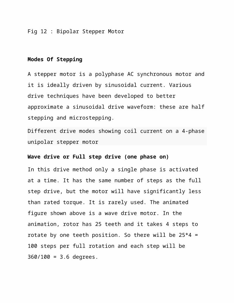
Fig 16 : RAMPS
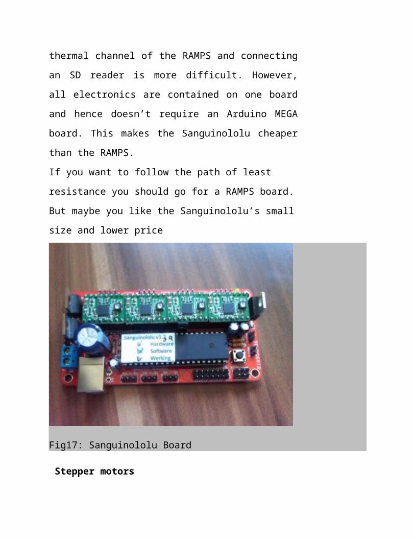
The Sanguinololu board is a more recent addition. It doesn’t
offer the extra thermal channel of the RAMPS and
connecting an SD reader is more difficult. However, all
electronics are contained on one board and hence doesn’t require
an Arduino MEGA board. This makes the Sanguinololu cheaper
than the RAMPS.
If you want to follow the path of least resistance you should go
for a RAMPS board. But maybe you like the Sanguinololu’s
small size and lower price
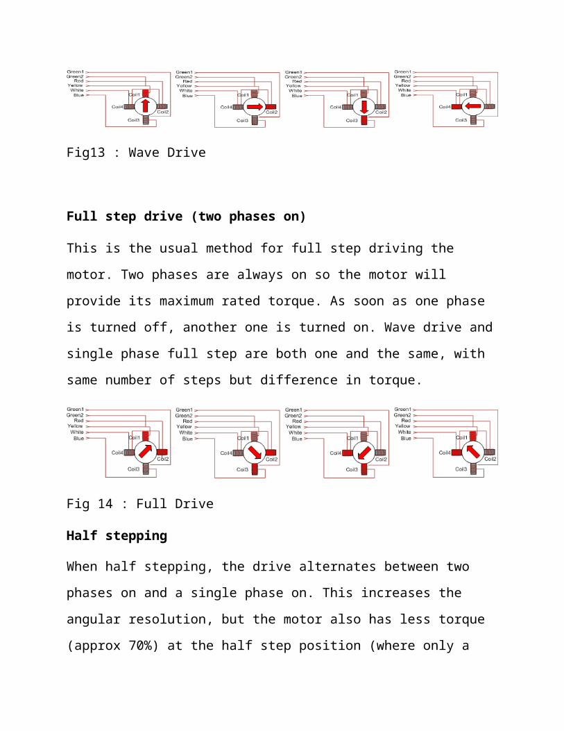
Fig17: Sanguinololu Board
Stepper motors
There are five stepper motors on the RepRap Prusa Mendel:
One to control the Y-axis
One to control the X-axis
Two to control the Z-axis
One to control the extruder
Normally all five motors on a printer are the same but this is not
required except for the two motors that control the Z-axis: these
must be identical. The RepRap Prusa Mendel has been designed
to use bipolar NEMA17 motors. NEMA17 determines some of
the dimensions of a stepper motor.

Fig18: Bipolar Stepper
The most important aspect of a stepper motor is its torque. However, the amount
of torque the motor will actually supply is also determined by the stepper
controller board.
End stops
At the start of a print job all three axes have to be moved to their
starting or homing position. This is the zero position of the
Cartesian robot. The axes can’t move any further than zero (they
can’t move to a negative position.)
To achieve this three end stops need to be installed, one for each
axis. A end stop needs to be installed at the position where the
axis shouldn’t move beyond:
For the X-axis this should be the position where the nozzle
reaches the left-hand side of the print plate.

For the Y-axis this should be on the back-side of the axis
so that the print plate is moved to the back far enough that
the nozzle ends up on the forward of the print plate.
For the Z-axis this should be the position where the nozzle
barely touches the print plate. When printing the software
will make sure the Z-axis is lifted a little before printing
the first layer.
There are two kinds of end stops: optical or mechanical
switch. The mechanical switches are preferred since they
are much cheaper, easier to install and work just as well as
optical end stops.
Fig 19: End Stops
SIMULATION
Proteus ISIS
Code
/*
Stepper Motor Control - one revolution
This program drives two unipolar or bipolar stepper motor.
The first motor is attached to digital pins 8 - 11 of the Arduino
And the second on digital pins 3-6.

The motor should revolve one revolution in one direction, then
one revolution in the other direction.
Created 23 Feb. 2014
by Jatin Batra
*/
#include <Stepper.h>
const int stepsPerRevolution = 200; // change this to fit the number of steps
per revolution
// for your motor
// initialize the stepper library on pins 8 through 11 and 3 through 6:
Stepper myStepper1(stepsPerRevolution, 8, 9, 10, 11);
Stepper myStepper2(stepsPerRevolution, 3,4,5,6);
void setup() {
// set the speed at 60 rpm:
myStepper1.setSpeed(60);
myStepper2.setSpeed(60);
// initialize the serial port:
Serial.begin(9600);
}
void loop() {
// step one revolution in one direction:
Serial.println("clockwise");
myStepper1.step(stepsPerRevolution);
myStepper2.step(stepsPerRevolution);
delay(500);

// step one revolution in the other direction:
Serial.println("counterclockwise");
myStepper1.step(-stepsPerRevolution);
myStepper2.step(-stepsPerRevolution);
delay(500);
}
CONCLUSION

THE BASIC CONCLUSON IS THAT THE 3D PRINTERS WILL CHANGE
THE WORLD. THE MOST IMPORTANT PART OF THE 3D PRINTERS AR
ELECTRONICS , THE MOTORS AND THEIR DRIVERS.A CUMBERSOME
AND A HECTIC TASK THAT COMES IN WAY OF 3D PRINTING IS THE
ELECTRONICS ITSLEF, WE THEREBY TEND TO MAKE SOME HOME-
MADE PROTOTYPES OF MULTI-AXIS STEPPER MOTOR DRIVERS
WHICH WILL BE COMPATIBLE WITH OPE-SOURCE FIRMWARES. A
PROCESSING CIRCUITRY TO UNDERSTAND THE G-CODES COMING
FROM THE 3D MODEL TO BE PRINTED HAS TO BE TRANSLATED IN A
LANGUAGE UNDERSTANDABLE BY PROCESSOR/MICRO-
CONTROLLER.THIS TASK IS DONE BY FIRMWARE ,TO CONTROL ,
REGULATE AND MANAGE STEPPER MOTOR , WE NEED DRIVERS.SOON
THERE WILL BE A TIME WHEN THERE WILL BE MASS USAGE OF 3D
PRINTERS ALL ACROOSS WORLD.THE CREDIT GOES TO OPEN-SOURCE
MOVEMENTS AND COMMUNITY LIKE REPRAP.
REFERENCES

1. http://www.engineersgarage.com/articles/stepper-motors?page=1 2. http://en.wikipedia.org/wiki/Stepper_motor 3. http://reprapbook.appspot.com/#d0e530 4. http://reprapbook.appspot.com/#d0e436 5. http://arduino.cc/en/Tutorial/StepperBipolar