ABSTRACf - uliege.be
10
Holographic interferometry using photorefractive crystals for quantitative phase measurement on large objects M.P. Georges and Ph.C. Lemaire Centre Spatialde Liege - Universite de Liege Pare Scientifique du Sart Tilman, Avenue du Pre-Aily 4031 ANGLEUR (LIEGE) -BELGIUM ABSTRACf We recently have presented a real-time holographic interferometer using sillenite crystals connected with phase- shifting for quantitative measurement of diffuse objects deformations. In our basic set-up, the crystal, sandwiched between two polarizers, is set in front of the optical head and followed by a CCD camera with an imaging objective. With this system, for conventional objects and using 2.2 Watts of Ar3+ laser power @ 514 nm, interferograms can be observed on object fields of about 30 cm x 20 cm (crystal size I cm x I cm and 26 mm objective focal length). In this paper we present investigations to increase the observed field in the existing system and to be able to use lower power lasers. Since setting the object at larger distances should lead to an un sufficient luminous level for hologram recording, we have proceeded by different ways. First, we use shorter focal length objectives, giving a larger field-of-view, and larger crystals have to be used in this case to avoid vignetting. Second, we use a large aperture frontal objective in order to collect more light and that images the object on the crystal, the fmal image being observed through relay imagery. Keywords: Holographic interferometry,photorefractive crystals 1. INTRODUCTION Attractive alternative media for hologram recording in holographic interferometry (HI)l are the photorefractive crystals (PRCs) of the sillenite family (Bi12Si020(BSO),Bi12Ge020(BOO),Bi12Ti020(BTO».2-9They can store phase holograms through refractive index modulation. The process is dynamic and reversible. In these crystals, the charge migration responsible of the hologram recording can take place under thermal diffusion (diffusive regime) and under an applied bias electric field (drift regime). In HI, the superimposition of the waves, corresponding to the two states of the tested object, leads to an intensity pattern that varies in function of the phase difference between both interfering fields. The interferogram has an intensity prof1.le/(u,v) given in each point (u,v) of an observation plane by : /(u,v)=/O(u,v)[I+ m(u,v) cos(l/>(u,v»)] (I) where /o(u,v) is the average intensity of the pattern, m(u,v) the modulation of the interference and tf>(u,v) the phase difference between the diffracted and transmitted wavefronts. In order to obtain the quantitative difference in term of displacement or deformation of the object, the quantity tf>(u,v) has to be determined from the intensity pattern (I). The phase-shifting method is currently used to calculate l/>(u.v) but requires at least 3 interferograms that are shifted in phase between each other. 248/ SPIE Vol. 2657 0-8194-2026-3/96/$6.00
Transcript of ABSTRACf - uliege.be
Holographic interferometry using photorefractive crystals for quantitative phase measurement on large objects
M.P. Georges and Ph.C. Lemaire
CentreSpatialde Liege - Universite de Liege
Pare Scientifique du Sart Tilman, Avenue du Pre-Aily
4031 ANGLEUR (LIEGE) -BELGIUM
ABSTRACf
We recently have presented a real-time holographic interferometer using sillenite crystals connected with phase-shifting for quantitative measurement of diffuse objects deformations. In our basic set-up, the crystal, sandwiched betweentwo polarizers, is set in front of the optical head and followed by a CCD camera with an imaging objective. With thissystem, for conventional objects and using 2.2 Watts of Ar3+ laser power @ 514 nm, interferograms can be observed onobject fields of about 30 cm x 20 cm (crystal size I cm x I cm and 26 mm objective focal length). In this paper wepresent investigations to increase the observed field in the existing system and to be able to use lower power lasers. Sincesetting the object at larger distances should lead to an unsufficient luminous level for hologram recording, we haveproceeded by different ways. First, we use shorter focal length objectives, giving a larger field-of-view, and larger crystalshave to be used in this case to avoid vignetting. Second, we use a large aperture frontal objective in order to collect morelight and that images the object on the crystal, the fmal image being observed through relay imagery.
Keywords: Holographic interferometry,photorefractive crystals
1. INTRODUCTION
Attractive alternative media for hologram recording in holographic interferometry (HI)l are the photorefractivecrystals (PRCs) of the sillenite family (Bi12Si020(BSO), Bi12Ge020(BOO), Bi12Ti020(BTO».2-9They can store phaseholograms through refractive index modulation. The process is dynamic and reversible. In these crystals, the chargemigration responsible of the hologram recording can take place under thermal diffusion (diffusive regime) and under anapplied bias electric field (drift regime).
In HI, the superimposition of the waves, corresponding to the two states of the tested object, leads to an intensitypattern that varies in function of the phase difference between both interfering fields. The interferogram has an intensityprof1.le/(u,v) given in each point (u,v) of an observation plane by :
/(u,v)=/O(u,v)[I+ m(u,v) cos(l/>(u,v»)] (I)
where /o(u,v) is the average intensity of the pattern, m(u,v) the modulation of the interference and tf>(u,v)the phasedifference between the diffracted and transmitted wavefronts. In order to obtain the quantitative difference in term ofdisplacement or deformation of the object, the quantity tf>(u,v)has to be determined from the intensity pattern (I). Thephase-shifting method is currently used to calculate l/>(u.v)but requires at least 3 interferograms that are shifted in phasebetweeneach other.
248/ SPIEVol. 2657 0-8194-2026-3/96/$6.00
Despite the dynamical behaviour of PRCs, we have shown the possibility to use them in real-time ID with diffuseobjects in connection with a phase-shifting algorithm.7.8 In the real-time process, a fll'Sthologram is recorded, the objectundergoes a deformation and the subsequent interferogram is observed by continuous readout. Due to the low level of lightcoming from the object, the storage time of the fIrst hologram in our crystal is long enough to permit capture of therequired phase-shifted interferograms. The main limitation of this method is that the object must not move between theacquistions.
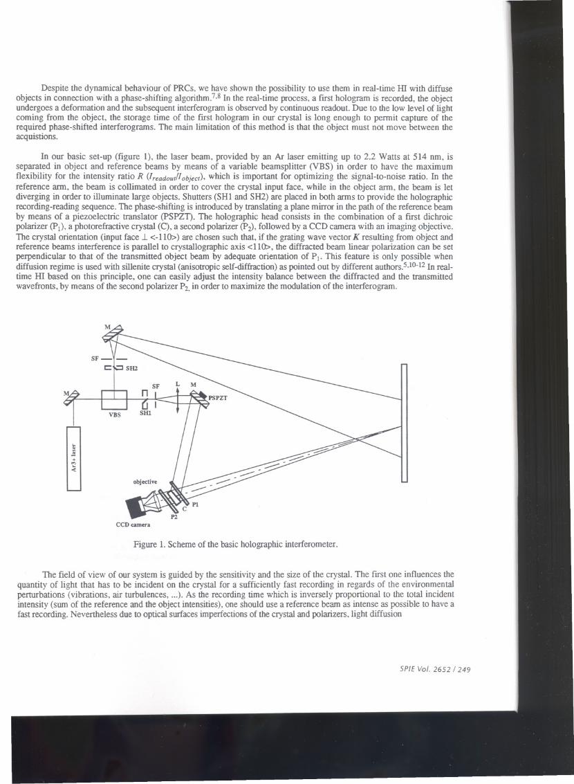
In our basic set-up (figure I), the laser beam, provided by an Ar laser emitting up to 2.2 Watts at 514 nm, isseparated in object and reference beams by means of a variable beamsplitter (VBS) in order to have the maximumflexibility for the intensity ratio R (/readour/!objecr),which is important for optimizing the signal-to-noise ratio. In thereference arm, the beam is collimated in order to cover the crystal input face, while in the object arm, the beam is letdiverging in order to illuminate large objects. Shutters (SRI and SH2) are placed in both arms to provide the holographicrecording-readingsequence.The phase-shiftingis introducedby translatinga plane mirror in thepath of the referencebeamby means of a piezoelectric translator (pSPZT). The holographic head consists in the combination of a first dichroicpolarizer (PI)' a photorefractivecrystal (C), a secondpolarizer(P:z),followedby a CCD camera with an imaging objective.The crystal orientation (input face.l <-110» are chosen such that, if the grating wave vector K resulting from object andreference beams interference is parallel to crystallographicaxis <110>, the diffracted beam linear polarization can be setperpendicular to that of the transmitted object beam by adequate orientation of PI' This feature is only possible whendiffusionregime is used with sillenitecrystal (anisotropicself-diffraction)as pointedout by different authors.5,lO-12In real-time HI based on this principle, one can easily adjust the intensity balance between the diffracted and the transmittedwavefronts,by means of the secondpolarizer P2,in order to maximizethe modulationof the interferograrn.
CCD camera
Figure 1. Scheme of the basic holographic interferometer.
The field of view of our system is guided by the sensitivity and the size of the crystal. The fll'Stone influences thequantity of light that has to be incident on the crystal for a sufficiently fast recording in regards of the environmentalperturbations (vibrations, air turbulences, ...). As the recording time which is inversely proportional to the total incidentintensity (sum of the reference and the object intensities), one should use a reference beam as intense as possible to have afast recording. Nevertheless due to optical surfaces imperfections of the crystal and polarizers, light diffusion
SPIEVol. 2652/249
occurs and we have to use a compromise between the diffracted intensity and the perturbative diffusion. So for a givenincident light power, the object has to be close enough to the crystal. In our first investigation with a crystal of BSO(from Sumitomo with I x I cm2 optical face), we observed that for practical application the object beam intensity at thelevel of the crystal (after PI) must be at least about 8 to 10J.lWatt/cm2.This level is reached, for white diffuse objects setat about 1.2 meter with 2W laser output. We had found an optimum value for R=lreil objof about 30. The second onelimits the angular field-of-view of the usable imaging objectivebecause of the vignetting,and as a consequence, its focallength must not be to short. For example, with the BSO described above, we are practically limited to a 26 mm focallength objective. With the maximal object distance of 1.2 m and for a CCD sensor of 6.5x5 mm2, the observed area istypically 30x20 cm2.
Our goal is to extend the performances of this first system with the double aim to visualize either I m2 objectswith the present Ar laser of 2W, or 0.25 m2objects with a power of about 400 mW (corresponding to small portable cwdiodepumpedfrequencydoubledYAG laser).
There are different ways to overcome the above described limitations. First, crystals can be grown now with a goodoptical quality to about 3x3 cm2 of optical face. Different species of BSO and BGO have been then acquired. Second, aobjective lens can be placed in front of the crystal in order to collect light and to image the object at the level of thecrystal. The image is then observed by the CCD via a second relay imagery.
2. PRESENTATION OF DIFFERENT OPTICAL SYSTEMS.
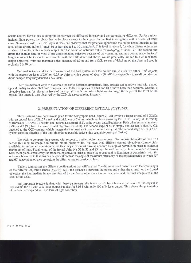
Three systems have been investigated for the holographichead (figure 2). All involve a larger crystal of BGO:Cuwith an optical face of 28x27 mm2 and a thicknessof 2.6 mm which has been grown by Prof. J. C. Launay at Universityof Bordeaux(PRAME). The first one, referedas systemI (S1), is the systemdescribedabove. Both other systems, systems2 (S2) and 3 (S3) have the same frontal objective lens (01). The second stage of 52 is simply another lens objective 02,attached to the CCD camera, which images the intermediate image close to the crystal. The second stage of 53 is a 4f-system enablingfiltering of the light (in order to possibly reduce high spatial frequencydiffusion).
We wish to compare the systems with respect to a given object area to cover. We impose the width of the CCDsensor (6.5 mm) to image a minimum 50 cm object width. We have tried different camera objectives commercialyavailable. An important condition is that these objectivesmust have an aperture as large as possible, in order to collect amaximum of light. Focal length of the frontal objective 01 in 52 and S3 mustbe well correctly chosen in order to have aback focal plane sufficiently far from the objective in order to place the crystal and to illuminate it completely with thereferencebeam. Note that this can be criticalbecause the angle of maximumefficiency of the crystal appears between 45°and 60° (dependingon the species),in the diffusiveregimeconsideredhere.
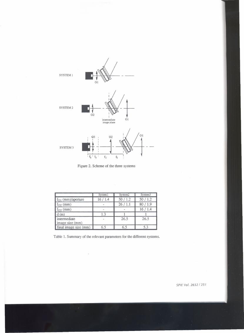
Table I summarizes the different configurationsthatwill be used. The different listed quantities are the focal lengthof the different objective lenses (fot. f02, f03), the distance d between the object and either the crystal, or the frontalobjective, the intermediate image size formedby the frontal objective close to the crystal and the final image size at thelevel of the CCD.
An important feature is that, with these parameters, the intensity of object beam at the level of the crystal is1OJ.LW/cm2for 51 with 2 W laser output but also for 52/53 with only 400 mW laser output. This shows the potentialityof the latters compared to 51 in term of light collection.
250/ SPIE Vol. 2652
SYSTEM 1
~~--
SYSTEM2~+--
02 II
intennediate 01imageplane
SYSTEM3
Figure 2. Scheme of the three systems
1.3 I 1M5
65 6.5 5.3
Table 1. Summary of the relevant parameters for the different systems.
SPIEVol. 2652 1251
3. COMP ARA'fiVE CHARACfERIZA 'fION OF THE SYSTEMS
10)The recording time
The angular distribution ~e of the object field entering in one point of the crystal is larger in systems with frontalobjective than in the other one. For 52/53, this distribution is given in function of the aperture and the back focal planedistance, Le., for the parameters listed above, ~e=38° in the center of the field-of-view. For SI, it is given by the objectsize and distance, Le. ~e=llo.
The diffraction efficiency being dependent on the angle between object and reference writing beams, and since thelatter is collimated, this could have the consequence that part of the object rays coming from one point through 01 do notenter in the crystal at the optimum angle, by vertue of what part of the collected light do not participate to the hologramrecording.
A good figure of merit for assessing this is to measure, for both 51 and 52/53, the time needed for the hologramrecording because it is inversely proportionalto the incidentintensities that interfere in the crystal.
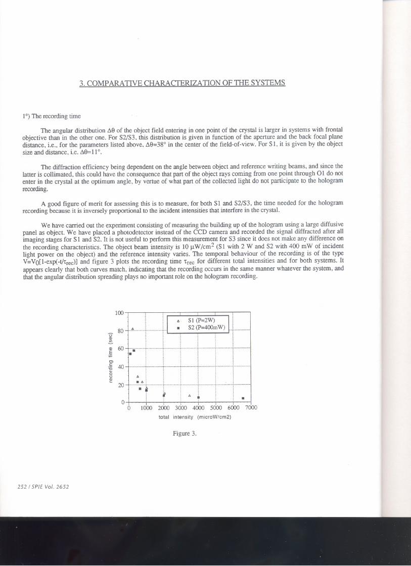
We have carried out the experiment consisting of measuring the building up of the hologram using a large diffusivepanel as object. We have placed a photodetector instead of the CCD camera and recorded the signal diffracted after allimaging stages for 51 and 52. It is not useful to perform this measurement for S3 since it does not make any difference onthe recording characteristics. The object beam intensity is to J.1W/cm2 (51 with 2 Wand 52 with 400 mW of incidentlight power on the object) and the reference intensity varies. The temporal behaviour of the recording is of the typeV=VO[l-exp(-t/'tree)] and figure 3 plots the recording time 'tree for different total intensities and for both systems. Itappears clearly that both curves match, indicating that the recording occurs in the same manner whatever the system, andthat the angular distribution spreading plays no important role on the hologram recording.
. . .. . .: : 6 SI (p=2W) :
L~mmmj "i S2liWJ!mmm
~ m";""""''''T mT'''''''''''r'''''''''T''''''''''T''''''''''''. . . . . .. . . . . .. . . . . .. . . . . .. . . . . .. . . . . .. . . . . .. . . . . .~.......................................... . . . . .. . . . . .. . . . . .. . . . . .. . . . . .6~ ~ ~ ~ ~ ~. . . . . .86: : : : : :. . . . . ., , , ,.............
8f ~ i 61 i i 8
o I i i i : i io 1000 2000 3000 4000 5000 6000 7000
total intensity (microW/cm2)
Figure 3.
252/ SPIE Vol. 2652
100
-0 80(J)
(J) 60,§C>c'i5 40<5<)2!
20
2°) The modulation of the interferogram observed
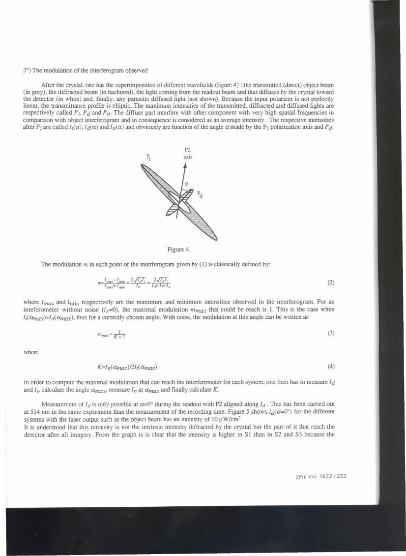
After the crystal, one has the superimposition of different wavefields (figure 4) : the transmitted (direct) object beam(in grey), the diffracted beam (in hachured), the light coming from the readout beam and that diffuses by the crystal towardthe detector (in white) and, finally, any parasitic diffused light (not shown). Because the input polarizer is not perfectlylinear, the transmittance profile is elliptic. The maximum intensities of the transmitted, diffracted and diffused lights arerespectively called PI, Pd and Pn. The diffuse part interfere with other component with very high spatial frequencies incomparison with object interferogram and in consequence is considered as an average intensity . The respective intensitiesafter P2are called It<ex),Id( ex)and In(ex)and obviously are function of the angle a made by the P2 polarization axis and Pd.
P2
Figure 4.
The modulation m in each point of the interferogram given by (1) is classically defmed by:
where Imax and Imin respectively are the maximum and minimum intensities observed in the interferogram. For aninteferometer without noise (In=O), the maximal modulation mmax that could be reach is 1. This is the case whenIrf...amax)=ItJ{amax),thus for a correctly chosen angle. With noise, the modulationat this angle can be written as
1"'mu =X+T
where
In order to compute the maximal modulation that can reach the interferometer for each system, one then has to measure Idand 1/, calculate the angle amax, measure In at amax and fmally calculate K.
Measurement of Id is only possible at 0:=0°during the readout with P2 aligned along Id. This has been carried outat 514 nm in the same experiment than the measurementof the recording time. Figure 5 shows Id(a=Q°)for the differentsystems with the laser output such as the object beam has an intensityof 10~W/cm2.It is understood that this intensity is not the intrinsic intensity diffracted by the crystal but the part of it that reach thedetector after all imagery. From the graph is is clear that the intensity is higher in SI than in S2 and S3 because the
SPIE Vol. 2652/253
(2)
(3)
(4)
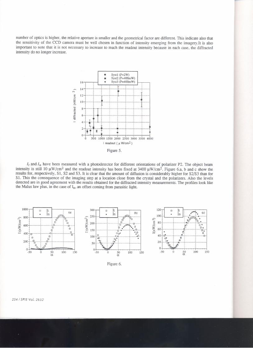
number of optics is higher, the relative aperture is smaller and the geometrical factor are different. This indicate also thatthe sensitivity of the CCD camera must be well chosen in function of intensity emerging from the imagery.!t is alsoimportant to note that it is not necessary to increase to much the readout intensity because in each case, the diffractedintensity do no longer increase.
. Systl(P=2W)
. Syst2(p=400mW)
:t't~t~I~Ei=1+:::::::::. ..... ..... ..... ....
I f j t j r...................m
}
I
...' ' ' : : :........... . . . . .. . . . . .. . . . . .. . . . . .. . . . . .. . . . . .. . . . . .. . . . . ..n .........................................................._...._..... . . . . .. . . . . .. . . . . .. . . . . .
t : : : : : :
~-t,i-l=T:rrI=I=o 1 i , i i i i i
o 500 1000 1500 2000 2500 3000 3500 4000
I readoul ( Ii W/cm2 )
Figure 5.
It and In have been measured with a photodetector for different orientations of polarizer P2. The object beamintensity is still 10 JlW/cm2 and the readout intensity has been fixed at 3400 JlW/cm2. Figure 6.a, b and c show theresults for, respectively, SI, S2 and S3. It is clear that the amount of diffusion is considerably higher for S2/S3 than forSI. This the consequence of the imaging step at a location close from the crystal and the polarizers. Also the levelsdetected are in good agreement with the results obtained for the diffracted intensity measurements.The profiles look likethe Malus law plus, in the case of In' an offset coming from parasitic light.
o-50 o 50
Cl100 150
254 I SPIE Vol. 2652
300: : (b)
f.m.~~..........
,oo{~:[~~f:..3:..~~50+".-'g~ : .;: :
-- 250ME~ 200~::- 150
o-50 o 50
Cl100 150o 50
CL100 150
Figure 6.
16
14'"
E 12<J;: 10.s"t:>Q)'5
6'5
4
2
The angle CXmaxof COITectbalance between Id and It can be now calculated by considering the following equality
Afterwards the cmves of In and Irare fitted witha sinesquaredfunctionandone deducesthe factorK by dividing the valuesof the fitted curves at amax and the maximum modulation can be determined using (3). The results are summarized intable 2
4. RESULTS
We have measured the deformation of a large panel reflecting diffusively. It has a dimension of 60 x 60 cm2 and isclamped to a metallic mount in order to have sufficient stability. Due to the rectangular shape of our CCD the observedarea is 50 x 40 cm2.The reference intensity is fixed at 2000 11W/cm2. The deformation is given by a static load at the rearside of the panel. The phase-shifting has been used at the readout for computing the phase map of the deformation.
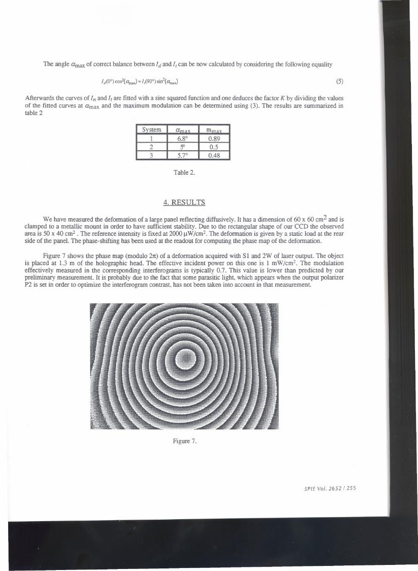
Figure 7 shows the phase map (modulo 21t) of a deformation acquired with SI and 2W of laser output. The objectis placed at 1.3 m of the holographic head. The effective incident power on this one is I mW/cm2. The modulationeffectively measured in the corresponding interferograms is typically 0.7. This value is lower than predicted by ourpreliminary measurement. It is probably due to the fact that some parasitic light, which appears when the output polarizerP2 is set in order to optimize the interferogram contrast, has not been taken into account in that measurement.
Figure 7.
SPIEVD/. 2652 1255
(5)
Svstem a",T m1 6.80 0.892 SO 0.53 5.70 0.48
Table 2.
..
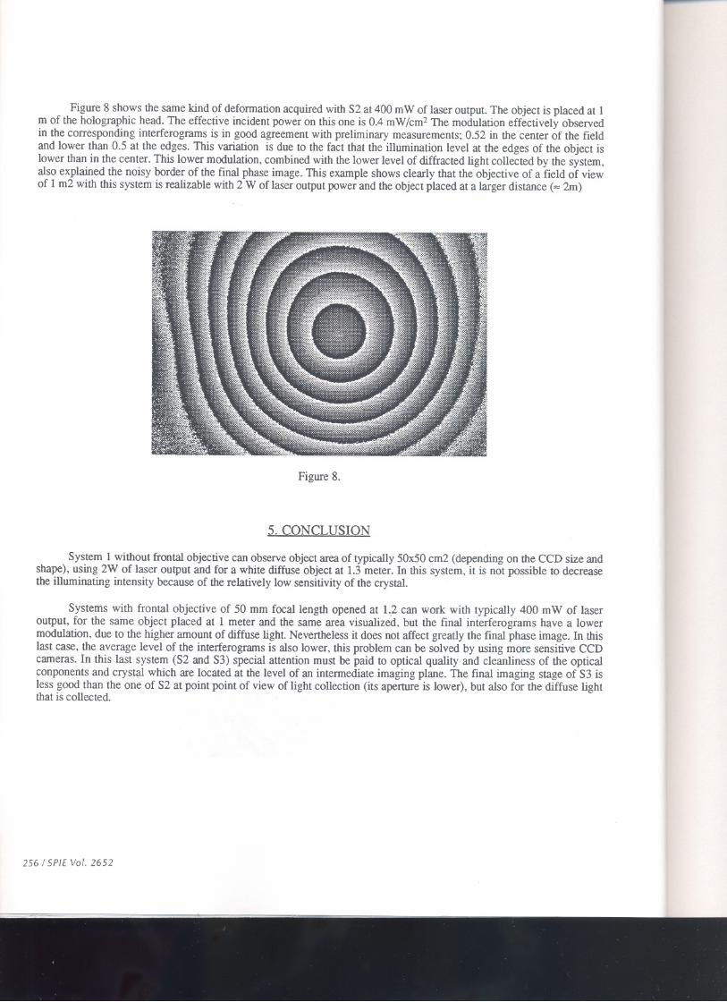
Figure 8 shows the same kind of defonnation acquired with S2 at 400 mW of laser output. The object is placed at Im of the holographic head. The effective incident power on this one is 0.4 mW/cm2 The modulation effectively observedin the corresponding interferograms is in good agreement with preliminary measurements; 0.52 in the center of the fieldand lower than 0.5 at the edges. This variation is due to the fact that the illumination level at the edges of the object islower than in the center. This lower modulation, combined with the lower level of diffracted light collected by the system,also explained the noisy border of the final phase image. This example shows clearly that the objective of a field of viewof 1 m2 with this system is realizable with 2 W of laser output power and the object placed at a larger distance (==2m)
Figure 8.
5. CONCLUSION
System 1 without frontal objective can observe object area of typically 50xSO cm2 (depending on the CCD size andshape), using 2W of laser output and for a white diffuse object at 1.3 meter. In this system, it is not possible to decreasethe illuminating intensity because of the relatively low sensitivity of the crystal.
Systems with frontal objective of 50 mm focal length opened at 1..2can work with typically 400 mW of laseroutput, for the same object placed at I meter and the same area visualized, but the final interferograms have a lowermodulation, due to the higher amount of diffuse light.Neverthelessit does not affect greatly the final phase image. In thislast case, the average level of the interferogramsis also lower, this problem can be solved by using more sensitive CCDcameras. In this last system (S2 and S3) special attention must be paid to optical quality and cleanliness of the opticalconponents and crystal which are located at the level of an intennediate imaging plane. The final imaging stage of S3 isless good than the one of S2 at point point of view of light collection (its aperture is lower), but also for the diffuse lightthat is collected.
256/SP1E Vo/. 2652
6. REFERENCES
1.Ed. P.K. Rastogi, Holographic interferometry: Principles and Methods, Springer Series in Optical Sciences, Vol 68,Springer-Verlag, Berlin, 1994.
2. Ed. P. Giinter and J.-P. Huignard,PhotorefracliveMaterials and their applications: Survey of Applications, Topics inApplied Physics, Vo162, Springer-Verlag,Berlin, 1989.
3. M.P. Petrov, S.I. Stepanov and A.V. Khomenko, Photorefractive crystals in Coherent Optical Systems, SpringerSeries in Optical Sciences, Vo159, Springer-Verlag,Berlin, 1991.
4. S.I. Stepanov, Rep. Prog. Phys., Vol. 57, WI, pp. 39-116, 1994.5. R.C. Troth and J.C. Dainty, Opt. Lett., 16 (I), p. 53-55 (1991)6. D. Dirksen and G. Von Bally, J. Opt. Soc. Am. B, 11 (9), p. 1858-1863(1994)7. M.P. Georges, Ph.C. Lemaire, "Real time holographic interferometer with BSO crystal using phase-shifting for
quantitative deformation measurements", Technical Digest ofNIST/OSA Conference on Photorefractive MaterialsEffects and Devices, Estes Park, Colorado,USA, paper WAI., June 1995.
8 M.P. Georges, Ph.C. Lemaire, "Phase-shifting real time interferometry that uses bismuth silicon oxide crystals",Applied Optics, Vol. 34, N°32, pp. 7497-7506,November 95.
9. L. Labrunie, G. Pauliat, J.-C. Launay and G. Roosen, "Unambiguousdetermination of object displacement in doubleexposure interferometry with photorefractive materials", Proceeding of ESO-SFO Conference on Optics andInformation, Mulhouse, France, paper 7.2, October 1995.
10. A.A. Kamshilin and M.P. Petrov, Opt. Comm., S3 (l), p. 23-26 (1985)11. S. Mallick, D. Rouede and A.G. Apostolidis, J. Opt. Soc. Am. B, 4 (8), p.1247-1259 (1987)12. A. Marrakchi, R.V. Johnson and A.R. Tanguay, Jr., J. Opt. Soc. Am. B, 3 (2), p.321-336 (1986)
SPJEVol. 2652/257