
Absorbed Dose Determination in External Beam Radiotherapy · for the radiation beams used in...
242
Absorbed Dose Determination in External Beam Radiotherapy An International Code of Practice for Dosimetry Based on Standards of Absorbed Dose to Water Sponsored by the IAEA, WHO, PAHO and ESTRO INTERNATIONAL ATOMIC ENERGY AGENCY, VIENNA, 2000 TECHNICAL REPORTS SERIES No. 398
Transcript of Absorbed Dose Determination in External Beam Radiotherapy · for the radiation beams used in...
Absorbed Dose Determination in External Beam Radiotherapy
An International Code of Practice for DosimetryBased on Standards of Absorbed Dose to Water
Sponsored by the IAEA, WHO, PAHO and ESTRO
INTERNATIONAL ATOMIC ENERGY AGENCY, VIENNA, 2000
TTEECCHHNNIICCAALL RREEPPOORRTTSS SSEERRIIEESS NNoo.. 398
ABSORBED DOSE DETERMINATIONIN EXTERNAL
BEAM RADIOTHERAPY
An International Code of Practice for DosimetryBased on Standards of Absorbed Dose to Water
© IAEA, 2000
Permission to reproduce or translate the information contained in this publica-tion may be obtained by writing to the International Atomic Energy Agency,Wagramer Strasse 5, P.O. Box 100, A-1400 Vienna, Austria.
Printed by the IAEA in AustriaDecember 2000
STI/DOC/010/398
ABSORBED DOSE DETERMINATIONIN EXTERNAL
BEAM RADIOTHERAPY
An International Code of Practice for DosimetryBased on Standards of Absorbed Dose to Water
TECHNICAL REPORTS SERIES No. 398
INTERNATIONAL ATOMIC ENERGY AGENCYVIENNA, 2000
FOREWORD
The International Atomic Energy Agency published in 1987 an InternationalCode of Practice entitled Absorbed Dose Determination in Photon and ElectronBeams (IAEA Technical Reports Series No. 277 (TRS-277)), recommending proce-dures to obtain the absorbed dose in water from measurements made with an ioniza-tion chamber in external beam radiotherapy. A second edition of TRS-277 waspublished in 1997 updating the dosimetry of photon beams, mainly kilovoltageX rays. Another International Code of Practice for radiotherapy dosimetry entitled‘The Use of Plane-Parallel Ionization Chambers in High Energy Electron and PhotonBeams’ (IAEA Technical Reports Series No. 381 (TRS-381)) was published in 1997to further update TRS-277 and complement it with respect to the area of parallel-plateionization chambers. Both codes have proven extremely valuable for users involvedin the dosimetry of the radiation beams used in radiotherapy. In TRS-277 the calibra-tion of the ionization chambers was based on primary standards of air kerma; thisprocedure was also used in TRS-381, but the new trend of calibrating ionizationchambers directly in a water phantom in terms of absorbed dose to water wasintroduced.
The development of primary standards of absorbed dose to water for highenergy photon and electron beams, and improvements in radiation dosimetryconcepts, offer the possibility of reducing the uncertainty in the dosimetry of radio-therapy beams. The dosimetry of kilovoltage X rays, as well as that of proton andheavy ion beams, interest in which has grown considerably in recent years, can alsobe based on these standards. Thus a coherent dosimetry system based on standards ofabsorbed dose to water is possible for practically all radiotherapy beams. ManyPrimary Standard Dosimetry Laboratories (PSDLs) already provide calibrations interms of absorbed dose to water at the radiation quality of 60Co gamma rays. Somelaboratories have extended calibrations to high energy photon and electron beams orare in the stage of developing the necessary techniques for these modalities.
Following the recommendations in 1996 of the IAEA Standing Advisory GroupScientific Committee of the IAEA (WHO) SSDL Network, a Co-ordinated ResearchProject was undertaken during 1997–1999 with the task of producing a new interna-tional Code of Practice based on standards of absorbed dose to water. The Code isalso endorsed by the World Health Organization, the Pan American HealthOrganization and the European Society of Therapeutic Radiology and Oncology(ESTRO). The final draft was reviewed by representatives of the organizationsendorsing the Code and by a large number of scientists.
This Code of Practice fulfils the need for a systematic and internationallyunified approach to the calibration of ionization chambers in terms of absorbed doseto water and to the use of these detectors in determining the absorbed dose to water
for the radiation beams used in radiotherapy. It provides a methodology for the deter-mination of absorbed dose to water in the low, medium and high energy photonbeams, electron beams, proton beams and heavy ion beams used for external radia-tion therapy. The officer at the IAEA responsible for this Code of Practice wasP. Andreo of the Division of Human Health.
EDITORIAL NOTE
Although great care has been taken to maintain the accuracy of information containedin this publication, neither the IAEA nor its Member States assume any responsibility forconsequences which may arise from its use.
The use of particular designations of countries or territories does not imply anyjudgement by the publisher, the IAEA, as to the legal status of such countries or territories, oftheir authorities and institutions or of the delimitation of their boundaries.
The mention of names of specific companies or products (whether or not indicated asregistered) does not imply any intention to infringe proprietary rights, nor should it beconstrued as an endorsement or recommendation on the part of the IAEA.
Reference to standards of other organizations is not to be construed as an endorsementon the part of the IAEA.
ABOUT THIS BOOK
The structure of this Code of Practice differs from that of TRS-277 and moreclosely resembles that of TRS-381 in that the practical recommendations and data foreach radiation type have been placed in an individual section devoted to that radiationtype. Each essentially forms a different Code of Practice and includes detailed proce-dures and worksheets.
The Code is addressed to users provided with calibrations in terms of absorbeddose to water traceable to a Primary Standard Dosimetry Laboratory. This category ofusers is likely to become the large majority since most standard laboratories areprepared to, or are planning to, supply calibrations in terms of absorbed dose to waterat the reference radiation qualities recommended in this Code of Practice. Users whoare not yet provided with calibrations in terms of absorbed dose to water may stillrefer to the current air kerma based codes of practice, such as TRS-277 and TRS-381,or adopt the present document using a calibration factor in terms of absorbed dose towater derived from an air kerma calibration as described in the text. Whatever proce-dure is employed, the user is strongly advised to verify exactly what physical quantityhas been selected for the calibration of the reference dosimeter in order to apply thecorrect formalism.
A list of abbreviations of organizations mentioned in this Code is given inSection 1.7.
Every user is invited to critically test this Code of Practice and submitcomments to:
Head, Dosimetry and Medical Radiation Physics Section,Division of Human Health,International Atomic Energy Agency,Wagramer Strasse 5,P.O. Box 100,A-1400 Vienna, AustriaE-mail: [email protected]: +43–1–26007
CONTENTS
1. INTRODUCTION . . . . . . . . . . . . . . . . . . . . . . . . . . . . . . . . . . . . . . . . . 1
1.1. Background . . . . . . . . . . . . . . . . . . . . . . . . . . . . . . . . . . . . . . . . . . 11.2. Advantages of a Code of Practice based on standards
of absorbed dose to water . . . . . . . . . . . . . . . . . . . . . . . . . . . . . . . 51.2.1. Reduced uncertainty . . . . . . . . . . . . . . . . . . . . . . . . . . . . . 51.2.2. A more robust system of primary standards . . . . . . . . . . . . 61.2.3. Use of a simple formalism . . . . . . . . . . . . . . . . . . . . . . . . 7
1.3. Types of radiation and range of beam qualities . . . . . . . . . . . . . . . 71.4. Practical use of this Code of Practice . . . . . . . . . . . . . . . . . . . . . . 81.5. Expression of uncertainties . . . . . . . . . . . . . . . . . . . . . . . . . . . . . . 91.6. Quantities and symbols . . . . . . . . . . . . . . . . . . . . . . . . . . . . . . . . . 91.7. Abbreviations of organizations . . . . . . . . . . . . . . . . . . . . . . . . . . . 14
2. FRAMEWORK . . . . . . . . . . . . . . . . . . . . . . . . . . . . . . . . . . . . . . . . . . . 15
2.1. The International Measurement System . . . . . . . . . . . . . . . . . . . . . 152.1.1. The IAEA/WHO network of SSDLs . . . . . . . . . . . . . . . . . 16
2.2. Standards of absorbed dose to water . . . . . . . . . . . . . . . . . . . . . . . 17
3. ND,w BASED FORMALISM . . . . . . . . . . . . . . . . . . . . . . . . . . . . . . . . . 21
3.1. Formalism . . . . . . . . . . . . . . . . . . . . . . . . . . . . . . . . . . . . . . . . . . . 213.1.1. Reference conditions . . . . . . . . . . . . . . . . . . . . . . . . . . . . . 213.1.2. Influence quantities . . . . . . . . . . . . . . . . . . . . . . . . . . . . . . 22
3.2. Correction for the radiation quality of the beam, kQ,Qo . . . . . . . . . 22
3.2.1. A modified kQ,Qofor electron beam cross-calibrations . . . . 24
3.3. Relation to NK based codes of practice . . . . . . . . . . . . . . . . . . . . . 26
4. IMPLEMENTATION . . . . . . . . . . . . . . . . . . . . . . . . . . . . . . . . . . . . . . . 27
4.1. General . . . . . . . . . . . . . . . . . . . . . . . . . . . . . . . . . . . . . . . . . . . . . 274.2. Equipment . . . . . . . . . . . . . . . . . . . . . . . . . . . . . . . . . . . . . . . . . . 29
4.2.1. Ionization chambers . . . . . . . . . . . . . . . . . . . . . . . . . . . . . 304.2.2. Measuring assembly . . . . . . . . . . . . . . . . . . . . . . . . . . . . . 384.2.3. Phantoms . . . . . . . . . . . . . . . . . . . . . . . . . . . . . . . . . . . . . 394.2.4. Waterproof sleeve for the chamber . . . . . . . . . . . . . . . . . . 414.2.5. Positioning of ionization chambers at the
reference depth . . . . . . . . . . . . . . . . . . . . . . . . . . . . . . . . . 41
4.3. Calibration of ionization chambers . . . . . . . . . . . . . . . . . . . . . . . . 444.3.1. Calibration in a 60Co beam . . . . . . . . . . . . . . . . . . . . . . . . 444.3.2. Calibration in kilovoltage X rays . . . . . . . . . . . . . . . . . . . . 464.3.3. Calibration at other qualities . . . . . . . . . . . . . . . . . . . . . . . 46
4.4. Reference dosimetry in the user beam . . . . . . . . . . . . . . . . . . . . . . 484.4.1. Determination of the absorbed dose to water . . . . . . . . . . . 484.4.2. Practical considerations for measurements in
the user beam . . . . . . . . . . . . . . . . . . . . . . . . . . . . . . . . . . 484.4.3. Correction for influence quantities . . . . . . . . . . . . . . . . . . 49
5. CODE OF PRACTICE FOR 60Co GAMMA RAY BEAMS . . . . . . . . . . . . . . . . . . . . . . . . . . . . . . . . . . . . . . . . . . . . 57
5.1. General . . . . . . . . . . . . . . . . . . . . . . . . . . . . . . . . . . . . . . . . . . . . . 575.2. Dosimetry equipment . . . . . . . . . . . . . . . . . . . . . . . . . . . . . . . . . . 57
5.2.1. Ionization chambers . . . . . . . . . . . . . . . . . . . . . . . . . . . . . 575.2.2. Phantoms and chamber sleeves . . . . . . . . . . . . . . . . . . . . . 57
5.3. Beam quality specification . . . . . . . . . . . . . . . . . . . . . . . . . . . . . . 585.4. Determination of absorbed dose to water . . . . . . . . . . . . . . . . . . . . 58
5.4.1. Reference conditions . . . . . . . . . . . . . . . . . . . . . . . . . . . . . 585.4.2. Determination of absorbed dose under
reference conditions . . . . . . . . . . . . . . . . . . . . . . . . . . . . . 595.4.3. Absorbed dose at zmax . . . . . . . . . . . . . . . . . . . . . . . . . . . . 60
5.5. Cross-calibration of field ionization chambers . . . . . . . . . . . . . . . . 605.6. Measurements under non-reference conditions . . . . . . . . . . . . . . . 60
5.6.1. Central axis depth dose distributions . . . . . . . . . . . . . . . . . 615.6.2. Output factors . . . . . . . . . . . . . . . . . . . . . . . . . . . . . . . . . . 61
5.7. Estimated uncertainty in the determination of absorbed dose to water under reference conditions . . . . . . . . . . . . 62
5.8. Worksheet . . . . . . . . . . . . . . . . . . . . . . . . . . . . . . . . . . . . . . . . . . . 64
6. CODE OF PRACTICE FOR HIGH ENERGY PHOTON BEAMS . . . . . 66
6.1. General . . . . . . . . . . . . . . . . . . . . . . . . . . . . . . . . . . . . . . . . . . . . . 666.2. Dosimetry equipment . . . . . . . . . . . . . . . . . . . . . . . . . . . . . . . . . . 66
6.2.1. Ionization chambers . . . . . . . . . . . . . . . . . . . . . . . . . . . . . 666.2.2. Phantoms and chamber sleeves . . . . . . . . . . . . . . . . . . . . . 67
6.3. Beam quality specification . . . . . . . . . . . . . . . . . . . . . . . . . . . . . . 686.3.1. Choice of beam quality index . . . . . . . . . . . . . . . . . . . . . . 686.3.2. Measurement of beam quality . . . . . . . . . . . . . . . . . . . . . . 69
6.4. Determination of absorbed dose to water . . . . . . . . . . . . . . . . . . . . 70
6.4.1. Reference conditions . . . . . . . . . . . . . . . . . . . . . . . . . . . . . 706.4.2. Determination of absorbed dose under
reference conditions . . . . . . . . . . . . . . . . . . . . . . . . . . . . . 706.4.3. Absorbed dose at zmax . . . . . . . . . . . . . . . . . . . . . . . . . . . . 71
6.5. Values for kQ,Qo . . . . . . . . . . . . . . . . . . . . . . . . . . . . . . . . . . . . . . . 75
6.5.1. Chamber calibrated in 60Co . . . . . . . . . . . . . . . . . . . . . . . . 756.5.2. Chamber calibrated in a series of photon
beam qualities . . . . . . . . . . . . . . . . . . . . . . . . . . . . . . . . . . 756.5.3. Chamber calibrated at Qo with generic
experimental kQ,Qovalues . . . . . . . . . . . . . . . . . . . . . . . . . 77
6.6. Cross-calibration of field ionization chambers . . . . . . . . . . . . . . . . 776.7. Measurements under non-reference conditions . . . . . . . . . . . . . . . 78
6.7.1. Central axis depth dose distributions . . . . . . . . . . . . . . . . . 786.7.2. Output factors . . . . . . . . . . . . . . . . . . . . . . . . . . . . . . . . . . 79
6.8. Estimated uncertainty in the determination of absorbed dose to water under reference conditions . . . . . . . . . . . . . . . . . . . . 79
6.9. Worksheet . . . . . . . . . . . . . . . . . . . . . . . . . . . . . . . . . . . . . . . . . . . 81
7. CODE OF PRACTICE FOR HIGH-ENERGY ELECTRON BEAMS . . 84
7.1. General . . . . . . . . . . . . . . . . . . . . . . . . . . . . . . . . . . . . . . . . . . . . . 847.2. Dosimetry equipment . . . . . . . . . . . . . . . . . . . . . . . . . . . . . . . . . . 84
7.2.1. Ionization chambers . . . . . . . . . . . . . . . . . . . . . . . . . . . . . 847.2.2. Phantoms and chamber sleeves . . . . . . . . . . . . . . . . . . . . . 85
7.3. Beam quality specification . . . . . . . . . . . . . . . . . . . . . . . . . . . . . . 867.3.1. Choice of beam quality index . . . . . . . . . . . . . . . . . . . . . . 867.3.2. Measurement of beam quality . . . . . . . . . . . . . . . . . . . . . . 86
7.4. Determination of absorbed dose to water . . . . . . . . . . . . . . . . . . . . 887.4.1. Reference conditions . . . . . . . . . . . . . . . . . . . . . . . . . . . . . 887.4.2. Determination of absorbed dose under
reference conditions . . . . . . . . . . . . . . . . . . . . . . . . . . . . . 897.4.3. Absorbed dose at zmax . . . . . . . . . . . . . . . . . . . . . . . . . . . . 90
7.5. Values for kQ,Qo . . . . . . . . . . . . . . . . . . . . . . . . . . . . . . . . . . . . . . . 90
7.5.1. Chamber calibrated in 60Co . . . . . . . . . . . . . . . . . . . . . . . . 907.5.2. Chamber calibrated at a series of
electron beam qualities . . . . . . . . . . . . . . . . . . . . . . . . . . . 907.6. Cross-calibration of ionization chambers . . . . . . . . . . . . . . . . . . . . 94
7.6.1. Cross-calibration procedure . . . . . . . . . . . . . . . . . . . . . . . . 947.6.2. Subsequent use of a cross-calibrated chamber . . . . . . . . . . 95
7.7. Measurements under non-reference conditions . . . . . . . . . . . . . . . 987.7.1. Central axis depth dose distributions . . . . . . . . . . . . . . . . . 98
7.7.2. Output factors . . . . . . . . . . . . . . . . . . . . . . . . . . . . . . . . . . 1017.8. Use of plastic phantoms . . . . . . . . . . . . . . . . . . . . . . . . . . . . . . . . 101
7.8.1. Scaling of depths . . . . . . . . . . . . . . . . . . . . . . . . . . . . . . . . 1027.8.2. Plastic phantoms for beam quality specification . . . . . . . . 1027.8.3. Plastic phantoms for absorbed dose determination at zref . . 1037.8.4. Plastic phantoms for depth dose distributions . . . . . . . . . . 103
7.9. Estimated uncertainty in the determination of absorbed dose to water under reference conditions . . . . . . . . . . . . . . . . . . . . 104
7.10. Worksheet . . . . . . . . . . . . . . . . . . . . . . . . . . . . . . . . . . . . . . . . . . . 107
8. CODE OF PRACTICE FOR LOW ENERGY KILOVOLTAGE X RAY BEAMS . . . . . . . . . . . . . . . . . . . . . . . . . . . . . 110
8.1. General . . . . . . . . . . . . . . . . . . . . . . . . . . . . . . . . . . . . . . . . . . . . . 1108.2. Dosimetry equipment . . . . . . . . . . . . . . . . . . . . . . . . . . . . . . . . . . 111
8.2.1. Ionization chambers . . . . . . . . . . . . . . . . . . . . . . . . . . . . . 1118.2.2. Phantoms . . . . . . . . . . . . . . . . . . . . . . . . . . . . . . . . . . . . . 112
8.3. Beam quality specification . . . . . . . . . . . . . . . . . . . . . . . . . . . . . . 1128.3.1. Choice of beam quality index . . . . . . . . . . . . . . . . . . . . . . 1128.3.2. Measurement of beam quality . . . . . . . . . . . . . . . . . . . . . . 114
8.4. Determination of absorbed dose to water . . . . . . . . . . . . . . . . . . . . 1158.4.1. Reference conditions . . . . . . . . . . . . . . . . . . . . . . . . . . . . . 1158.4.2. Determination of absorbed dose under
reference conditions . . . . . . . . . . . . . . . . . . . . . . . . . . . . . 1158.5. Values for kQ,Qo
. . . . . . . . . . . . . . . . . . . . . . . . . . . . . . . . . . . . . . . 1168.6. Measurements under non-reference conditions . . . . . . . . . . . . . . . 117
8.6.1. Central axis depth dose distributions . . . . . . . . . . . . . . . . . 1178.6.2. Output factors . . . . . . . . . . . . . . . . . . . . . . . . . . . . . . . . . . 117
8.7. Estimated uncertainty in the determination of absorbed dose to water under reference conditions . . . . . . . . . . . . 118
8.8. Worksheet . . . . . . . . . . . . . . . . . . . . . . . . . . . . . . . . . . . . . . . . . . . 120
9. CODE OF PRACTICE FOR MEDIUM ENERGY KILOVOLTAGE X RAY BEAMS . . . . . . . . . . . . . . . . . . . . . . . . . . . . . 122
9.1. General . . . . . . . . . . . . . . . . . . . . . . . . . . . . . . . . . . . . . . . . . . . . . 1229.2. Dosimetry equipment . . . . . . . . . . . . . . . . . . . . . . . . . . . . . . . . . . 123
9.2.1. Ionization chambers . . . . . . . . . . . . . . . . . . . . . . . . . . . . . 1239.2.2. Phantoms and chamber sleeves . . . . . . . . . . . . . . . . . . . . . 124
9.3. Beam quality specification . . . . . . . . . . . . . . . . . . . . . . . . . . . . . . 1259.3.1. Choice of beam quality index . . . . . . . . . . . . . . . . . . . . . . 125
9.3.2. Measurement of beam quality . . . . . . . . . . . . . . . . . . . . . . 1269.4. Determination of absorbed dose to water . . . . . . . . . . . . . . . . . . . . 127
9.4.1. Reference conditions . . . . . . . . . . . . . . . . . . . . . . . . . . . . . 1279.4.2. Determination of absorbed dose under
reference conditions . . . . . . . . . . . . . . . . . . . . . . . . . . . . . 1279.5. Values for kQ,Qo
. . . . . . . . . . . . . . . . . . . . . . . . . . . . . . . . . . . . . . . 1279.6. Measurements under non-reference conditions . . . . . . . . . . . . . . . 129
9.6.1. Central axis depth dose distributions . . . . . . . . . . . . . . . . . 1299.6.2. Output factors . . . . . . . . . . . . . . . . . . . . . . . . . . . . . . . . . . 131
9.7. Estimated uncertainty in the determination of absorbed dose to water under reference conditions . . . . . . . . . . . . 131
9.8. Worksheet . . . . . . . . . . . . . . . . . . . . . . . . . . . . . . . . . . . . . . . . . . . 133
10. CODE OF PRACTICE FOR PROTON BEAMS . . . . . . . . . . . . . . . . . . 135
10.1. General . . . . . . . . . . . . . . . . . . . . . . . . . . . . . . . . . . . . . . . . . . . . . 13510.2. Dosimetry equipment . . . . . . . . . . . . . . . . . . . . . . . . . . . . . . . . . . 137
10.2.1. Ionization chambers . . . . . . . . . . . . . . . . . . . . . . . . . . . . . 13710.2.2. Phantoms and chamber sleeves . . . . . . . . . . . . . . . . . . . . . 137
10.3. Beam quality specification . . . . . . . . . . . . . . . . . . . . . . . . . . . . . . 13810.3.1. Choice of beam quality index . . . . . . . . . . . . . . . . . . . . . . 13810.3.2. Measurement of beam quality . . . . . . . . . . . . . . . . . . . . . . 139
10.4. Determination of absorbed dose to water . . . . . . . . . . . . . . . . . . . . 14010.4.1. Reference conditions . . . . . . . . . . . . . . . . . . . . . . . . . . . . . 14010.4.2. Determination of absorbed dose under
reference conditions . . . . . . . . . . . . . . . . . . . . . . . . . . . . . 14110.5. Values for kQ,Qo
. . . . . . . . . . . . . . . . . . . . . . . . . . . . . . . . . . . . . . . 14110.6. Measurements under non-reference conditions . . . . . . . . . . . . . . . 141
10.6.1. Central axis depth dose distributions . . . . . . . . . . . . . . . . . 14510.6.2. Output factors . . . . . . . . . . . . . . . . . . . . . . . . . . . . . . . . . . 14610.6.3. Use of plastic phantoms for relative dosimetry . . . . . . . . . 146
10.7. Estimated uncertainty in the determination of absorbed dose to water under reference conditions . . . . . . . . . . . . 148
10.8. Worksheet . . . . . . . . . . . . . . . . . . . . . . . . . . . . . . . . . . . . . . . . . . . 149
11. CODE OF PRACTICE FOR HEAVY ION BEAMS . . . . . . . . . . . . . . . 151
11.1. General . . . . . . . . . . . . . . . . . . . . . . . . . . . . . . . . . . . . . . . . . . . . . 15111.2. Dosimetry equipment . . . . . . . . . . . . . . . . . . . . . . . . . . . . . . . . . . 154
11.2.1. Ionization chambers . . . . . . . . . . . . . . . . . . . . . . . . . . . . . 15411.2.2. Phantoms and chamber sleeves . . . . . . . . . . . . . . . . . . . . . 155
11.3. Beam quality specification . . . . . . . . . . . . . . . . . . . . . . . . . . . . . . 15611.4. Determination of absorbed dose to water . . . . . . . . . . . . . . . . . . . . 156
11.4.1. Reference conditions . . . . . . . . . . . . . . . . . . . . . . . . . . . . . 15611.4.2. Determination of absorbed dose under
reference conditions . . . . . . . . . . . . . . . . . . . . . . . . . . . . . 15711.5. Values for kQ,Qo
. . . . . . . . . . . . . . . . . . . . . . . . . . . . . . . . . . . . . . . 15711.6. Measurements under non-reference conditions . . . . . . . . . . . . . . . 15811.7. Estimated uncertainty in the determination of
absorbed dose to water under reference conditions . . . . . . . . . . . . 16011.8. Worksheet . . . . . . . . . . . . . . . . . . . . . . . . . . . . . . . . . . . . . . . . . . . 162
APPENDIX I. RELATION BETWEEN NK AND ND,w BASED CODES OF PRACTICE . . . . . . . . . . . . . . . . . . . . . . . . . . . 165
I.1. 60Co and high energy photon and electron beams . . . . . . . . . . . . . 165I.1.1. A summary of notations used for calibration factors . . . . . 169I.1.2. Comparison of Dw determinations . . . . . . . . . . . . . . . . . . . 169
I.2. Kilovoltage X ray beams . . . . . . . . . . . . . . . . . . . . . . . . . . . . . . . . 172
APPENDIX II. CALCULATION OF kQ,QoAND ITS UNCERTAINTY . . . . 174
II.1. General . . . . . . . . . . . . . . . . . . . . . . . . . . . . . . . . . . . . . . . . . . . . . 174II.2. 60Co gamma radiation . . . . . . . . . . . . . . . . . . . . . . . . . . . . . . . . . . 175
II.2.1. Value for sw,air in 60Co . . . . . . . . . . . . . . . . . . . . . . . . . . . . 175II.2.2. Value for Wair in 60Co . . . . . . . . . . . . . . . . . . . . . . . . . . . . 175II.2.3. Values for pQ in 60Co . . . . . . . . . . . . . . . . . . . . . . . . . . . . 175II.2.4. Summary of values and uncertainties in 60Co . . . . . . . . . . 178
II.3. High energy photon beams . . . . . . . . . . . . . . . . . . . . . . . . . . . . . . 178II.3.1. Values for sw,air in high energy photon beams . . . . . . . . . . 178II.3.2. Value for Wair in high energy photon beams . . . . . . . . . . . 178II.3.3. Values for pQ in high energy photon beams . . . . . . . . . . . . 181II.3.4. Summary of uncertainties in high energy photon beams . . 183
II.4. Electron beams . . . . . . . . . . . . . . . . . . . . . . . . . . . . . . . . . . . . . . . 185II.4.1. Values for sw,air in electron beams . . . . . . . . . . . . . . . . . . . 185II.4.2. Value for Wair in electron beams . . . . . . . . . . . . . . . . . . . . 186II.4.3. Values for pQ in electron beams . . . . . . . . . . . . . . . . . . . . 186II.4.4. Summary of uncertainties in electron beams . . . . . . . . . . . 189
II.5. Proton beams . . . . . . . . . . . . . . . . . . . . . . . . . . . . . . . . . . . . . . . . 190II.5.1. Values for sw,air in proton beams . . . . . . . . . . . . . . . . . . . . 190II.5.2. Value for Wair in proton beams . . . . . . . . . . . . . . . . . . . . . 192II.5.3. Values for pQ in proton beams . . . . . . . . . . . . . . . . . . . . . . 192
II.5.4. Summary of uncertainties in proton beams . . . . . . . . . . . . 193II.6. Heavy ion beams . . . . . . . . . . . . . . . . . . . . . . . . . . . . . . . . . . . . . . 194
II.6.1. Value for sw,air in heavy ion beams . . . . . . . . . . . . . . . . . . 194II.6.2. Value for Wair in heavy ion beams . . . . . . . . . . . . . . . . . . . 196II.6.3. Value for pQ in heavy ion beams . . . . . . . . . . . . . . . . . . . . 196II.6.4. Summary of uncertainties in heavy ion beams . . . . . . . . . . 196
APPENDIX III. PHOTON BEAM QUALITY SPECIFICATION . . . . . . . . . 198
III.1. Overview of common photon beam quality specifiers . . . . . . . . . . 198III.2. Advantages and disadvantages of TPR20,10 . . . . . . . . . . . . . . . . . . 200III.3. Advantages and disadvantages of PDD(10)x . . . . . . . . . . . . . . . . . 203III.4. Concluding remarks . . . . . . . . . . . . . . . . . . . . . . . . . . . . . . . . . . . 208
APPENDIX IV. EXPRESSION OF UNCERTAINTIES . . . . . . . . . . . . . . . . . 210
IV.1. General considerations on errors and uncertainties . . . . . . . . . . . . 210IV.2. Type A standard uncertainties . . . . . . . . . . . . . . . . . . . . . . . . . . . . 211IV.3. Type B standard uncertainties . . . . . . . . . . . . . . . . . . . . . . . . . . . . 212IV.4. Combined and expanded uncertainties . . . . . . . . . . . . . . . . . . . . . . 213
REFERENCES . . . . . . . . . . . . . . . . . . . . . . . . . . . . . . . . . . . . . . . . . . . . . . . . 215
CONTRIBUTORS TO DRAFTING AND REVIEW . . . . . . . . . . . . . . . . . . . . 226
RELATED IAEA PUBLICATIONS . . . . . . . . . . . . . . . . . . . . . . . . . . . . . . . . 229
1
1. INTRODUCTION
1.1. BACKGROUND
In its Report 24 on ‘Determination of Absorbed Dose in a Patient Irradiated byBeams of X or Gamma Rays in Radiotherapy Procedures’, the InternationalCommission on Radiation Units and Measurements (ICRU) [1] concluded that“although it is too early to generalize, the available evidence for certain types oftumour points to the need for an accuracy of ±5% in the delivery of an absorbed doseto a target volume if the eradication of the primary tumour is sought”. The ICRUcontinues, “Some clinicians have requested even closer limits such as ±2%, but atthe present time (in 1976) it is virtually impossible to achieve such a standard”.These statements were made in a context where uncertainties were estimated at the95% confidence level, and have been interpreted as if they correspond to approxi-mately two standard deviations. Thus the requirement for an accuracy of 5% in thedelivery of absorbed dose would correspond to a combined uncertainty of 2.5% atthe level of one standard deviation. Today it is considered that a goal in dose deliveryto the patient based on such an accuracy requirement is too strict and the figureshould be increased to about one standard deviation of 5%, but there are no definiterecommendations in this respect.1 The requirement for an accuracy of ±5% could,on the other hand, also be interpreted as a tolerance of the deviation between the pre-scribed dose and the dose delivered to the target volume. Modern radiotherapy hasconfirmed, in any case, the need for high accuracy in dose delivery if new tech-niques, including dose escalation in 3-D conformal radiotherapy, are to be applied.Emerging technologies in radiotherapy, for example modern diagnostic tools for thedetermination of the target volume, 3-D commercial treatment planning systems andadvanced accelerators for irradiation, can only be fully utilized if there is highaccuracy in dose determination and delivery.
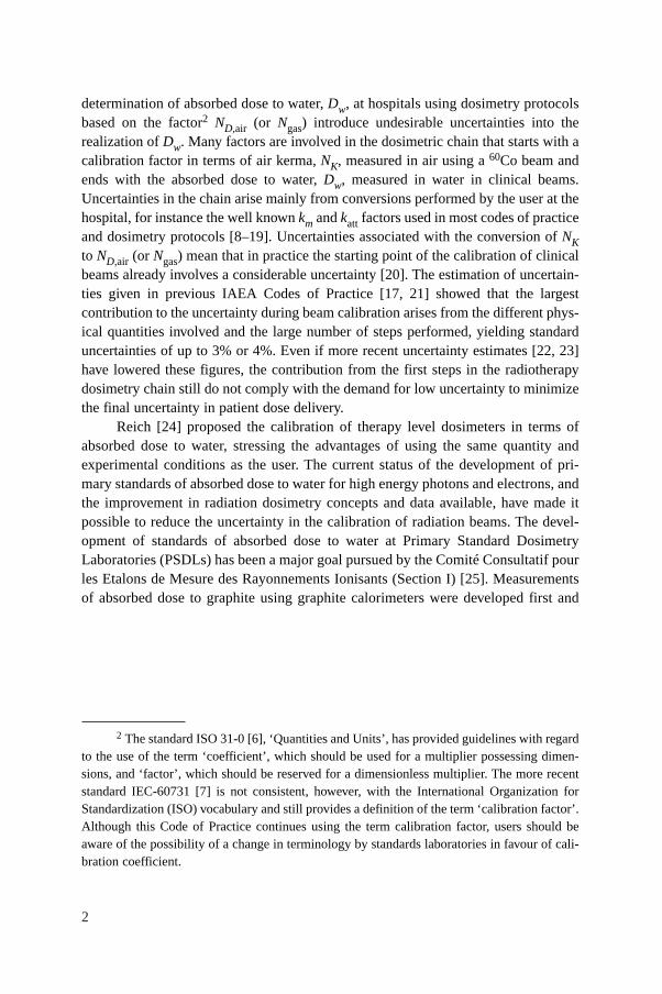
The various steps between the calibration of ionization chambers in terms ofthe quantity air kerma, Kair, at the standardizing dosimetry laboratories and the
1 Several studies have concluded that for certain types of tumors the combined standarduncertainty in dose delivery should be smaller than 3.3% or 3.5% [2–4], “even if in many caseslarger values are acceptable and in some special cases even smaller values should be aimedat” [3]. It has also been stated that taking into account the uncertainties in dose calculationalgorithms, a more appropriate limit for the combined standard uncertainty of the dosedelivered to the target volume would be around 5% [4, 5].
2
determination of absorbed dose to water, Dw, at hospitals using dosimetry protocolsbased on the factor2 ND,air (or Ngas) introduce undesirable uncertainties into therealization of Dw. Many factors are involved in the dosimetric chain that starts with acalibration factor in terms of air kerma, NK, measured in air using a 60Co beam andends with the absorbed dose to water, Dw, measured in water in clinical beams.Uncertainties in the chain arise mainly from conversions performed by the user at thehospital, for instance the well known km and katt factors used in most codes of practiceand dosimetry protocols [8–19]. Uncertainties associated with the conversion of NKto ND,air (or Ngas) mean that in practice the starting point of the calibration of clinicalbeams already involves a considerable uncertainty [20]. The estimation of uncertain-ties given in previous IAEA Codes of Practice [17, 21] showed that the largestcontribution to the uncertainty during beam calibration arises from the different phys-ical quantities involved and the large number of steps performed, yielding standarduncertainties of up to 3% or 4%. Even if more recent uncertainty estimates [22, 23]have lowered these figures, the contribution from the first steps in the radiotherapydosimetry chain still do not comply with the demand for low uncertainty to minimizethe final uncertainty in patient dose delivery.
Reich [24] proposed the calibration of therapy level dosimeters in terms ofabsorbed dose to water, stressing the advantages of using the same quantity andexperimental conditions as the user. The current status of the development of pri-mary standards of absorbed dose to water for high energy photons and electrons, andthe improvement in radiation dosimetry concepts and data available, have made itpossible to reduce the uncertainty in the calibration of radiation beams. The devel-opment of standards of absorbed dose to water at Primary Standard DosimetryLaboratories (PSDLs) has been a major goal pursued by the Comité Consultatif pourles Etalons de Mesure des Rayonnements Ionisants (Section I) [25]. Measurementsof absorbed dose to graphite using graphite calorimeters were developed first and
2 The standard ISO 31-0 [6], ‘Quantities and Units’, has provided guidelines with regardto the use of the term ‘coefficient’, which should be used for a multiplier possessing dimen-sions, and ‘factor’, which should be reserved for a dimensionless multiplier. The more recentstandard IEC-60731 [7] is not consistent, however, with the International Organization forStandardization (ISO) vocabulary and still provides a definition of the term ‘calibration factor’.Although this Code of Practice continues using the term calibration factor, users should beaware of the possibility of a change in terminology by standards laboratories in favour of cali-bration coefficient.
continue to be used in many laboratories. This procedure was considered as an inter-mediate step between air kerma and direct determination of the absorbed dose towater, since absolute calorimetric measurements in water are more problematic.Comparisons of determinations of absorbed dose to graphite were satisfactory and,consequently, the development of standards of absorbed dose to water was under-taken in some laboratories. Procedures to determine absorbed dose to water usingmethods to measure appropriate base or derived quantities have considerablyimproved at the PSDLs in the last decade. The well established procedures are theionization method, chemical dosimetry, and water and graphite calorimetry.Although only the water calorimeter allows the direct determination of the absorbeddose to water in a water phantom, the required conversion and perturbation factorsfor the other procedures are now well known at many laboratories. These develop-ments lend support to a change in the quantity used at present to calibrate ionizationchambers and provide calibration factors in terms of absorbed dose to water, ND,w,for use in radiotherapy beams. Many PSDLs already provide ND,w calibrations at60Co gamma ray beams and some laboratories have extended these calibration pro-cedures to high energy photon and electron beams; others are developing the neces-sary techniques for such modalities.
At Secondary Standard Dosimetry Laboratories (SSDLs), calibration factorsfrom a PSDL or from the Bureau International des Poids et Mesures (BIPM) aretransferred to hospital users. For 60Co gamma ray beams, most SSDLs can provideusers with a calibration factor in terms of absorbed dose to water without much exper-imental effort, as all SSDLs have such beams. However, it is not possible for them, ingeneral, to supply experimentally determined calibration factors at high energyphoton and electron beams. Numerical calculations of a beam quality correctionfactor, related to 60Co, can, however, be performed which should be equivalent tothose obtained experimentally but with a larger uncertainty.
A major advance in radiotherapy over the last few years has been the increasinguse of proton and heavy ion irradiation facilities for radiation therapy. Practicaldosimetry in these fields is also based on the use of ionization chambers that may beprovided with calibrations both in terms of air kerma and in terms of absorbed doseto water, therefore the dosimetry procedures developed for high energy photons andelectrons can also be applicable to protons and heavy ions. At the other extreme of therange of available teletherapy beams lie kilovoltage X ray beams, and for these theuse of standards of absorbed dose to water was introduced in IAEA Technical ReportsSeries No. 277 (TRS-277) [17]. However, for kilovoltage X rays there are, at present,very few laboratories providing ND,w calibrations because most PSDLs have not yetestablished primary standards of absorbed dose to water for such radiation qualities.Nevertheless, ND,w calibrations in kilovoltage X ray beams may be provided byPSDLs and SSDLs based on their standards of air kerma and one of the currentdosimetry protocols for X ray beams. Thus a coherent dosimetry system based on
3
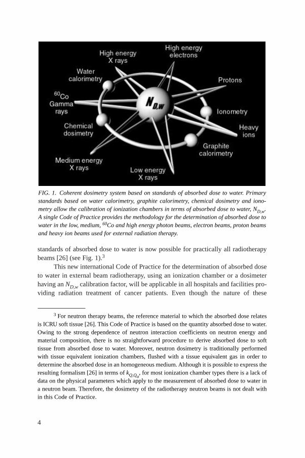
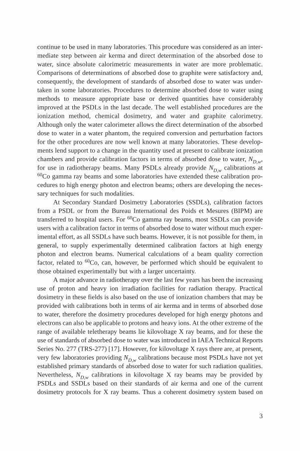
standards of absorbed dose to water is now possible for practically all radiotherapybeams [26] (see Fig. 1).3
This new international Code of Practice for the determination of absorbed doseto water in external beam radiotherapy, using an ionization chamber or a dosimeterhaving an ND,w calibration factor, will be applicable in all hospitals and facilities pro-viding radiation treatment of cancer patients. Even though the nature of these
4
3 For neutron therapy beams, the reference material to which the absorbed dose relatesis ICRU soft tissue [26]. This Code of Practice is based on the quantity absorbed dose to water.Owing to the strong dependence of neutron interaction coefficients on neutron energy andmaterial composition, there is no straightforward procedure to derive absorbed dose to softtissue from absorbed dose to water. Moreover, neutron dosimetry is traditionally performedwith tissue equivalent ionization chambers, flushed with a tissue equivalent gas in order todetermine the absorbed dose in an homogeneous medium. Although it is possible to express theresulting formalism [26] in terms of kQ,Qo
, for most ionization chamber types there is a lack ofdata on the physical parameters which apply to the measurement of absorbed dose to water ina neutron beam. Therefore, the dosimetry of the radiotherapy neutron beams is not dealt within this Code of Practice.
FIG. 1. Coherent dosimetry system based on standards of absorbed dose to water. Primarystandards based on water calorimetry, graphite calorimetry, chemical dosimetry and iono-metry allow the calibration of ionization chambers in terms of absorbed dose to water, ND,w.A single Code of Practice provides the methodology for the determination of absorbed dose towater in the low, medium, 60Co and high energy photon beams, electron beams, proton beamsand heavy ion beams used for external radiation therapy.
institutions may be widely different, this Code of Practice will serve as a useful doc-ument to the medical physics and radiotherapy community and help achieve unifor-mity and consistency in radiation dose delivery throughout the world. The Code ofPractice should also be of value to the IAEA/WHO network of SSDLs in improvingthe accuracy and consistency of their dose determination, and thereby the standard-ization of radiation dosimetry in the many countries which they serve.
1.2. ADVANTAGES OF A CODE OF PRACTICE BASED ON STANDARDS OFABSORBED DOSE TO WATER
Absorbed dose to water is the quantity of main interest in radiation therapy,since this quantity relates closely to the biological effects of radiation. The advantagesof calibrations in terms of absorbed dose to water and dosimetry procedures usingthese calibration factors have been presented by several authors [20, 27, 28] and aredescribed in detail in an ICRU report on photon dosimetry [29]. A summary of themost relevant aspects is given below.
1.2.1. Reduced uncertainty
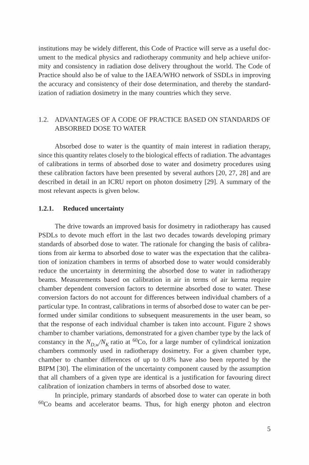
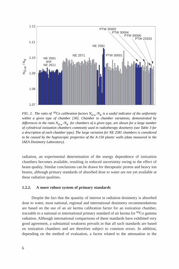
The drive towards an improved basis for dosimetry in radiotherapy has causedPSDLs to devote much effort in the last two decades towards developing primarystandards of absorbed dose to water. The rationale for changing the basis of calibra-tions from air kerma to absorbed dose to water was the expectation that the calibra-tion of ionization chambers in terms of absorbed dose to water would considerablyreduce the uncertainty in determining the absorbed dose to water in radiotherapybeams. Measurements based on calibration in air in terms of air kerma requirechamber dependent conversion factors to determine absorbed dose to water. Theseconversion factors do not account for differences between individual chambers of aparticular type. In contrast, calibrations in terms of absorbed dose to water can be per-formed under similar conditions to subsequent measurements in the user beam, sothat the response of each individual chamber is taken into account. Figure 2 showschamber to chamber variations, demonstrated for a given chamber type by the lack ofconstancy in the ND,w/NK ratio at 60Co, for a large number of cylindrical ionizationchambers commonly used in radiotherapy dosimetry. For a given chamber type,chamber to chamber differences of up to 0.8% have also been reported by theBIPM [30]. The elimination of the uncertainty component caused by the assumptionthat all chambers of a given type are identical is a justification for favouring directcalibration of ionization chambers in terms of absorbed dose to water.
In principle, primary standards of absorbed dose to water can operate in both60Co beams and accelerator beams. Thus, for high energy photon and electron
5
radiation, an experimental determination of the energy dependence of ionizationchambers becomes available, resulting in reduced uncertainty owing to the effect ofbeam quality. Similar conclusions can be drawn for therapeutic proton and heavy ionbeams, although primary standards of absorbed dose to water are not yet available atthese radiation qualities.
1.2.2. A more robust system of primary standards
Despite the fact that the quantity of interest in radiation dosimetry is absorbeddose to water, most national, regional and international dosimetry recommendationsare based on the use of an air kerma calibration factor for an ionization chamber,traceable to a national or international primary standard of air kerma for 60Co gammaradiation. Although international comparisons of these standards have exhibited verygood agreement, a substantial weakness prevails in that all such standards are basedon ionization chambers and are therefore subject to common errors. In addition,depending on the method of evaluation, a factor related to the attenuation in the
6
1.07
1.08
1.09
1.10
1.11
1.12 N
NE 2561and
NE 2611
NE 2571
NE 2581
PTW 30001
PTW 30002
PTW 30006PTW 23333
D,w
/ N
K
PTW 30004
FIG. 2. The ratio of 60Co calibration factors ND,w /NK is a useful indicator of the uniformitywithin a given type of chamber [30]. Chamber to chamber variations, demonstrated bydifferences in the ratio ND,w /NK for chambers of a given type, are shown for a large numberof cylindrical ionization chambers commonly used in radiotherapy dosimetry (see Table 3 fora description of each chamber type). The large variation for NE 2581 chambers is consideredto be caused by the hygroscopic properties of the A-150 plastic walls (data measured in theIAEA Dosimetry Laboratory).
chamber wall entering into the determination of the quantity air kerma has been foundto differ by up to 0.7% for some primary standards [31]. In contrast, primarystandards of absorbed dose to water are based on a number of different physicalprinciples. There are no assumptions or estimated correction factors common to all ofthem. Therefore, good agreement among these standards (see Section 2.2) gives muchgreater confidence in their accuracy.
1.2.3. Use of a simple formalism
The formalism given in Ref. [17] and in most national and internationaldosimetry protocols for the determination of absorbed dose to water in radiotherapybeams is based on the application of several coefficients, perturbation and other cor-rection factors. This is because of the practical difficulty in making the conversionfrom the free-air quantity air kerma to the in-phantom quantity absorbed dose to water.This complexity is best demonstrated by considering the equations needed, and theprocedures for selecting the appropriate data. Reliable information about certain phys-ical characteristics of the ionization chamber used is also required. Many of these data,such as displacement correction factors and stopping-power ratios, are derived fromcomplex measurements or calculations based on theoretical models. A simplified pro-cedure starting from a calibration factor in terms of absorbed dose to water, andapplying correction factors for all influence quantities, reduces the possibility of errorsin the determination of absorbed dose to water in the radiation beam. The simplicity ofthe formalism in terms of absorbed dose to water becomes obvious when the generalequation for the determination of absorbed dose to water is considered (see Section 3).
1.3. TYPES OF RADIATION AND RANGE OF BEAM QUALITIES
This Code of Practice provides a methodology for the determination ofabsorbed dose to water in the low, medium and high energy photon beams, electronbeams, proton beams and heavy ion beams used for external radiation therapy. Theranges of radiation qualities covered in this report are given below (for a descriptionof the beam quality index see the corresponding sections):(a) Low energy X rays with generating potentials up to 100 kV and HVL of 3 mm
Al (the lower limit is determined by the availability of standards);4
7
4 The boundary between the two ranges for kilovoltage X rays is not strict and has anoverlap between 80 kV, 2 mm Al and 100 kV, 3 mm Al. In this overlap region, the methods forabsorbed dose determination given in Sections 8 or 9 are equally satisfactory, and whichever ismore convenient should be used.
(b) Medium energy X rays with generating potentials above 80 kV and HVL of2 mm Al (see footnote 4);
(c) 60Co gamma radiation;(d) High energy photons generated by electrons with energies in the interval
1–50 MeV, with TPR20,10 values between 0.50 and 0.84;(e) Electrons in the energy interval 3–50 MeV, with a half-value depth, R50,
between 1 and 20 g/cm2; (f) Protons in the energy interval 50–250 MeV, with a practical range, Rp, between
0.25 and 25 g/cm2;(g) Heavy ions with Z between 2 (He) and 18 (Ar) having a practical range in water,
Rp, of 2 to 30 g/cm2 (for carbon ions this corresponds to an energy range of100 MeV/u to 450 MeV/u, where u is the atomic mass unit).
1.4. PRACTICAL USE OF THIS CODE OF PRACTICE
Emphasis has been given to making the practical use of this report as simple aspossible. The structure of this Code of Practice differs from that of TRS-277 [17] andmore closely resembles Technical Reports Series No. 381 (TRS-381) [21] in that thepractical recommendations and data for each radiation type have been placed in anindividual section devoted to that radiation type. Each essentially forms a differentCode of Practice, including detailed procedures and worksheets. The reader can per-form a dose determination for a given beam by working through the appropriate sec-tion; the search for procedures or tables contained in other parts of the document hasbeen reduced to a minimum. Making the various Codes of Practice independent andself-contained has required an unavoidable repetition of some portions of text, but thisis expected to result in a publication which is simple and easy to use, especially forusers having access to a limited number of radiation types. The first four sections con-tain general concepts that apply to all radiation types. Appendices provide a comple-ment to the information supplied in the various sections.
Compared with previous codes of practice or dosimetry protocols based onstandards of air kerma (see Refs [17, 21]), the adoption of this Code of Practice willintroduce small differences in the value of the absorbed dose to water determined inclinical beams. Detailed comparisons will be published in the open literature, and theresults are expected to depend on the type and quality of the beam and on the type ofionization chamber. Where differences arise, it is important to notice that they mightbe due to: (i) inaccuracies in the numerical factors and expressions (for example km,pwall, etc.) in the NK based method and, to a lesser extent, in this Code of Practice, and(ii) the primary standards to which the calibrations in terms of air kerma and absorbeddose to water are traceable. Even for 60Co gamma radiation, which is generally better
8
characterized than other modalities, beam calibrations based on the two differentstandards, Kair and Dw, differ by typically 1% (see Appendix I); the value derivedusing this Code of Practice is considered to be the better estimate. Any conclusionsdrawn from comparisons between protocols based on standards of air kerma andabsorbed dose to water must take account of the differences between primary stan-dards.
1.5. EXPRESSION OF UNCERTAINTIES
The evaluation of uncertainties in this Code of Practice follows the guidancegiven by the ISO [32]. Uncertainties of measurements are expressed as relative stan-dard uncertainties and the evaluation of standard uncertainties is classified into typeA and type B. The method of evaluation of type A standard uncertainty is by statis-tical analysis of a series of observations, whereas the method of evaluation of type Bstandard uncertainty is based on means other than statistical analysis of a series ofobservations. A practical implementation of the ISO recommendations, based on thesummaries provided in Refs [33] and [17], is given for completeness in Appendix IVof this Code of Practice.
Estimates of the uncertainty in dose determination for the different radiationtypes are given in the appropriate sections. Compared with estimates in previouscodes of practice, the present values are generally smaller. This arises from the greaterconfidence in determinations of absorbed dose to water based on Dw standards and,in some cases, from a more rigorous analysis of uncertainties in accordance with theISO guidelines.
1.6. QUANTITIES AND SYMBOLS
Most of the symbols used in this Code of Practice are identical to those used inRefs [17] and [21], and only a few are new in the context of standards of absorbeddose to water. For completeness, a summary is provided here for all quantities ofrelevance to the different methods used in this Code of Practice.
cpl Material dependent scaling factor to convert ranges and depths mea-sured in plastic phantoms into the equivalent values in water. Thisapplies to electron, proton and heavy ion beams. Note that in this Codeof Practice the depths and ranges are defined in units of g/cm2, in con-trast to their definition in cm in Ref. [21] for electron beams. As a
9
result, the values given for cpl in this Code for electrons differ fromthose for Cpl given in Ref. [21]. The use of lowercase for cpl denotesthis change.
csda Continuous slowing down approximation.Dw,Q Absorbed dose to water at the reference depth, zref, in a water phantom
irradiated by a beam of quality Q. The subscript Q is omitted when thereference beam quality is 60Co. Unit: gray (Gy).
Eo, Ez Mean energy of an electron beam at the phantom surface and at depthz, respectively. Unit: MeV.
hpl Material dependent fluence scaling factor to correct for the differencein electron fluence in plastic compared with that in water at an equiva-lent depth.
HVL Half-value layer, used as a beam quality index for low and mediumenergy X ray beams.
ki General correction factor used in the formalism to correct for the effectof the difference in the value of an influence quantity between thecalibration of a dosimeter under reference conditions in the standardslaboratory and the use of the dosimeter in the user facility underdifferent conditions.
kelec Calibration factor of an electrometer.kh Factor to correct the response of an ionization chamber for the effect of
humidity if the chamber calibration factor is referred to dry air.kpol Factor to correct the response of an ionization chamber for the effect of
a change in polarity of the polarizing voltage applied to the chamber.kQ,Qo
Factor to correct for the difference between the response of an ioniza-tion chamber in the reference beam quality Qo used for calibrating thechamber and in the actual user beam quality Q. The subscript Qo isomitted when the reference quality is 60Co gamma radiation (i.e. thereduced notation kQ always corresponds to the reference quality 60Co).
ks Factor to correct the response of an ionization chamber for the lack ofcomplete charge collection (due to ion recombination).
kTP Factor to correct the response of an ionization chamber for the effect ofthe difference that may exist between the standard reference tempera-ture and pressure specified by the standards laboratory and the temper-ature and pressure of the chamber in the user facility under differentenvironmental conditions.
MQ Reading of a dosimeter at quality Q, corrected for influence quantitiesother than beam quality. Unit: C or rdg.
Mem Reading of a dosimeter used as an external monitor. Unit: C or rdg.(µen/ρ)m1,m2 ratio of the mean mass energy absorption coefficients of materials m1
and m2, averaged over a photon spectrum.
10
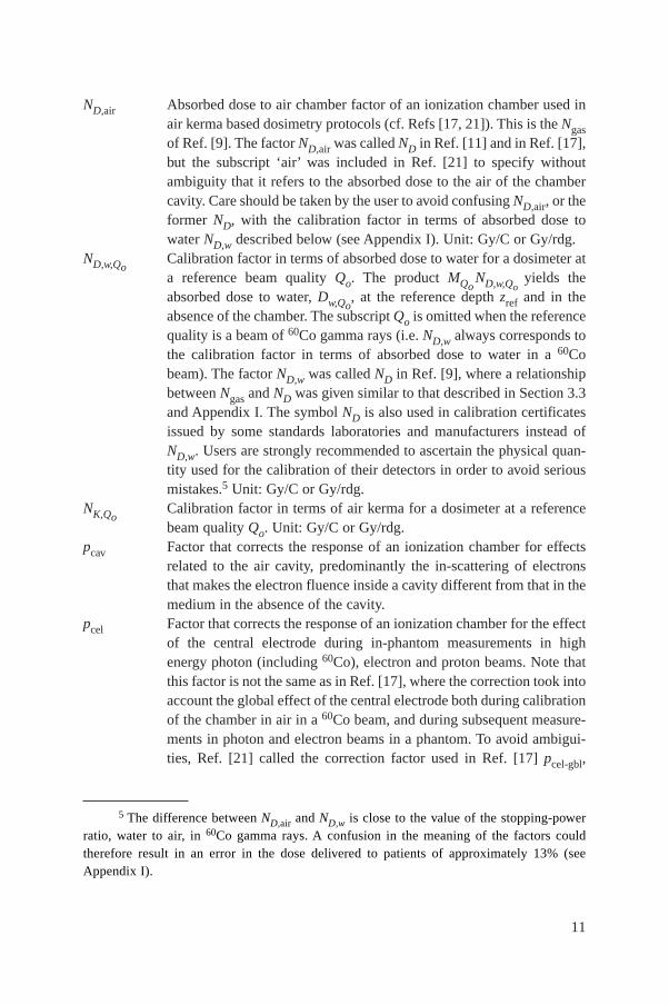
ND,air Absorbed dose to air chamber factor of an ionization chamber used inair kerma based dosimetry protocols (cf. Refs [17, 21]). This is the Ngasof Ref. [9]. The factor ND,air was called ND in Ref. [11] and in Ref. [17],but the subscript ‘air’ was included in Ref. [21] to specify withoutambiguity that it refers to the absorbed dose to the air of the chambercavity. Care should be taken by the user to avoid confusing ND,air, or theformer ND, with the calibration factor in terms of absorbed dose towater ND,w described below (see Appendix I). Unit: Gy/C or Gy/rdg.
ND,w,QoCalibration factor in terms of absorbed dose to water for a dosimeter ata reference beam quality Qo. The product MQo
ND,w,Qoyields the
absorbed dose to water, Dw,Qo, at the reference depth zref and in the
absence of the chamber. The subscript Qo is omitted when the referencequality is a beam of 60Co gamma rays (i.e. ND,w always corresponds tothe calibration factor in terms of absorbed dose to water in a 60Cobeam). The factor ND,w was called ND in Ref. [9], where a relationshipbetween Ngas and ND was given similar to that described in Section 3.3and Appendix I. The symbol ND is also used in calibration certificatesissued by some standards laboratories and manufacturers instead ofND,w. Users are strongly recommended to ascertain the physical quan-tity used for the calibration of their detectors in order to avoid seriousmistakes.5 Unit: Gy/C or Gy/rdg.
NK,QoCalibration factor in terms of air kerma for a dosimeter at a referencebeam quality Qo. Unit: Gy/C or Gy/rdg.
pcav Factor that corrects the response of an ionization chamber for effectsrelated to the air cavity, predominantly the in-scattering of electronsthat makes the electron fluence inside a cavity different from that in themedium in the absence of the cavity.
pcel Factor that corrects the response of an ionization chamber for the effectof the central electrode during in-phantom measurements in highenergy photon (including 60Co), electron and proton beams. Note thatthis factor is not the same as in Ref. [17], where the correction took intoaccount the global effect of the central electrode both during calibrationof the chamber in air in a 60Co beam, and during subsequent measure-ments in photon and electron beams in a phantom. To avoid ambigui-ties, Ref. [21] called the correction factor used in Ref. [17] pcel-gbl,
11
5 The difference between ND,air and ND,w is close to the value of the stopping-powerratio, water to air, in 60Co gamma rays. A confusion in the meaning of the factors couldtherefore result in an error in the dose delivered to patients of approximately 13% (seeAppendix I).
keeping the symbol pcel exclusively for in-phantom measurements (seeAppendix I).
PDD Percentage depth dose.pdis Factor that accounts for the effect of replacing a volume of water with
the detector cavity when the reference point of the chamber6 is taken tobe at the chamber centre. It is the alternative to the use of an effectivepoint of measurement of the chamber, Peff. For plane-parallel ioniza-tion chambers, pdis is not required.
Peff The effective point of measurement of an ionization chamber. For thestandard calibration geometry, i. e. a radiation beam incident from onedirection, Peff is shifted from the position of the centre towards thesource by a distance which depends on the type of beam and chamber.For plane-parallel ionization chambers Peff is usually assumed to be sit-uated in the centre of the front surface of the air cavity.7 The concept ofthe effective point of measurement of a cylindrical ionization chamberwas used for all radiation types in Ref. [17], but in this Code of Practiceit is only used for electron and heavy ion beams. For other beams, ref-erence dosimetry is based on positioning the reference point of thechamber at the reference depth, zref, where the dose is determined. Thereference point of an ionization chamber is specified for each radiationtype in the corresponding section.
pQ Overall perturbation factor for an ionization chamber for in-phantommeasurements at a beam quality Q. It is equal to the product of variousfactors correcting for different effects, each correcting for small pertur-bations; in practice these are pcav, pcel, pdis and pwall.
pwall Factor that corrects the response of an ionization chamber for the non-medium equivalence of the chamber wall and any waterproofingmaterial.
Q General symbol to indicate the quality of a radiation beam. A subscript‘o’, i.e. Qo, indicates the reference quality used for the calibration of anionization chamber or a dosimeter.
rdg Value, in arbitrary units, used for the reading of a dosimeter.
12
6 The reference point of a chamber is specified in this Code of Practice in each sectionfor each type of chamber. It usually refers to the point of the chamber specified by a calibra-tion document to be that at which the calibration factor applies [33].
7 This assumption might fail if the chamber design does not follow certain requirementsregarding the ratio of cavity diameter to cavity height as well as that of guard ring width tocavity height (see Ref. [21]).
R50 Half-value depth in water (in g/cm2), used as the beam quality index forelectron beams.
Rp Practical range (in g/cm2) for electron, proton and heavy ion beams.Rres Residual range (in g/cm2) for proton beams.rcyl Cavity radius of a cylindrical ionization chamber.SAD Source–axis distance.SCD Source–chamber distance.SOBP Spread-out Bragg peak.SSD Source–surface distance.sm,air Stopping-power ratio medium to air, defined as the ratio of the mean
restricted mass stopping powers of materials m and air, averaged overan electron spectrum. For all high energy radiotherapy beams in thisCode of Practice, except for heavy ion beams, stopping-power ratiosare of the Spencer–Attix type with a cut-off energy ∆ = 10 keV (seeRef. [11]).
TMR Tissue–maximum ratio.TPR20,10 Tissue–phantom ratio in water at depths of 20 and 10 g/cm2, for a field
size of 10 cm × 10 cm and an SCD of 100 cm, used as the beam qualityindex for high energy photon radiation.
uc Combined standard uncertainty of a quantity.Wair The mean energy expended in air per ion pair formed.zmax Depth of maximum dose (in g/cm2).zref Reference depth (in g/cm2) for in-phantom measurements. When
specified at zref, the absorbed dose to water refers to Dw,Q at the inter-section of the beam central axis with the plane defined by zref.
13

14
1.7. ABBREVIATIONS OF ORGANIZATIONS
The following abbreviations are used in this report to refer to different organi-zations involved in radiation dosimetry:
ARPANSA Australian Radiation Protection and Nuclear Safety Agency, AustraliaBEV Bundesamt für Eich- und Vermessungswesen, AustriaBIPM Bureau International des Poids et MesuresCCEMRI(I) Comité Consultatif pour les Etalons de Mesure des Rayonnements
Ionisants (Section I) (Consultative Committee for Standards of Ionizing Radiation). Since September 1997, the CCEMRI and its sections have been renamed CCRI.
CCRI(I) Comité Consultatif des Rayonnements Ionisants (Section I) (Consultative Committee for Ionizing Radiation)
CIPM Comité International des Poids et MesuresENEA- Ente per le Nuove Tecnologie, l’Energia e l’Ambiente, Instituto
INMRI Nazionale di Metrologia delle Radiazioni Ionizzanti, ItalyICRU International Commission on Radiation Units and MeasurementsIEC International Electrotechnical CommissionIMS International Measurement SystemISO International Organization for StandardizationLPRI Laboratoire Primaire de Métrologie des Rayonnements Ionisants,
FranceNIST National Institute of Standards and Technology, USANPL National Physical Laboratory, United KingdomNRC National Research Council, CanadaNRL National Radiation Laboratory, New ZealandOIML Organisation Internationale de Métrologie LégalePTB Physikalisch-Technische Bundesanstalt, Germany
15
2. FRAMEWORK
2.1. THE INTERNATIONAL MEASUREMENT SYSTEM
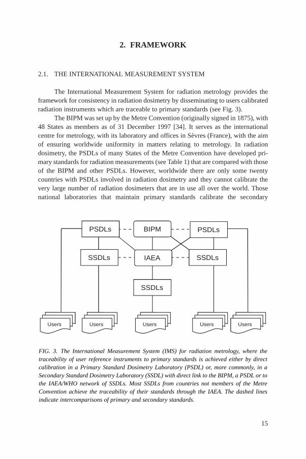
The International Measurement System for radiation metrology provides theframework for consistency in radiation dosimetry by disseminating to users calibratedradiation instruments which are traceable to primary standards (see Fig. 3).
The BIPM was set up by the Metre Convention (originally signed in 1875), with48 States as members as of 31 December 1997 [34]. It serves as the internationalcentre for metrology, with its laboratory and offices in Sèvres (France), with the aimof ensuring worldwide uniformity in matters relating to metrology. In radiationdosimetry, the PSDLs of many States of the Metre Convention have developed pri-mary standards for radiation measurements (see Table 1) that are compared with thoseof the BIPM and other PSDLs. However, worldwide there are only some twentycountries with PSDLs involved in radiation dosimetry and they cannot calibrate thevery large number of radiation dosimeters that are in use all over the world. Thosenational laboratories that maintain primary standards calibrate the secondary
FIG. 3. The International Measurement System (IMS) for radiation metrology, where thetraceability of user reference instruments to primary standards is achieved either by directcalibration in a Primary Standard Dosimetry Laboratory (PSDL) or, more commonly, in aSecondary Standard Dosimetry Laboratory (SSDL) with direct link to the BIPM, a PSDL or tothe IAEA/WHO network of SSDLs. Most SSDLs from countries not members of the MetreConvention achieve the traceability of their standards through the IAEA. The dashed linesindicate intercomparisons of primary and secondary standards.
PSDLs
SSDLs
SSDLs
PSDLs
SSDLs
BIPM
IAEA
Users Users Users Users Users
16
standards of SSDLs (see Table 1), which in turn calibrate the reference instrumentsof users (some PSDLs also calibrate the reference instruments of users).
2.1.1. The IAEA/WHO network of SSDLs
The main role of the SSDLs is to bridge the gap between PSDLs and the usersof ionizing radiation by enabling the transfer of dosimeter calibrations from the
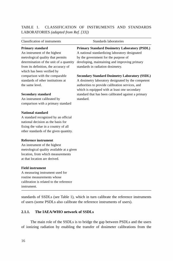
TABLE 1. CLASSIFICATION OF INSTRUMENTS AND STANDARDSLABORATORIES (adapted from Ref. [33])
Classification of instruments Standards laboratories
Primary standard Primary Standard Dosimetry Laboratory (PSDL)An instrument of the highest A national standardizing laboratory designated metrological quality that permits by the government for the purpose of determination of the unit of a quantity developing, maintaining and improving primaryfrom its definition, the accuracy of standards in radiation dosimetry.which has been verified by comparison with the comparable Secondary Standard Dosimetry Laboratory (SSDL)standards of other institutions at A dosimetry laboratory designated by the competent the same level. authorities to provide calibration services, and
which is equipped with at least one secondarySecondary standard standard that has been calibrated against a primaryAn instrument calibrated by standard.comparison with a primary standard
National standardA standard recognized by an official national decision as the basis for fixing the value in a country of all other standards of the given quantity.
Reference instrumentAn instrument of the highest metrological quality available at a givenlocation, from which measurements at that location are derived.
Field instrumentA measuring instrument used for routine measurements whose calibration is related to the referenceinstrument.
17
primary standard to user instruments [35]. In 1976, a network of SSDLs was estab-lished as a joint effort by the IAEA and WHO in order to disseminate calibrations tousers by providing the link between users and primary standards, mainly for countriesthat are not members of the Metre Convention. By 2000, the network included 73 lab-oratories and 6 SSDL national organizations in 61 IAEA Member States, of whichover half are in developing countries. The SSDL network also includes 20 affiliatedmembers, among them the BIPM, several national PSDLs, the ICRU and other inter-national organizations that provide support to the network [36].
As the organizer of the network, the IAEA has the responsibility to verify thatthe services provided by the SSDL member laboratories follow internationallyaccepted metrological standards (including traceability for radiation protectioninstruments). The first step in this process is the dissemination of dosimeter calibra-tions from the BIPM or PSDLs through the IAEA to the SSDLs. In the next step,follow-up programmes and dose quality audits are implemented by the IAEA for theSSDLs to guarantee that the standards disseminated to users are kept within the levelsof accuracy required by the IMS [36].
One of the principal goals of the SSDL network in the field of radiotherapydosimetry is to guarantee that the dose delivered to patients undergoing radiotherapytreatment is within internationally accepted levels of accuracy. This is accomplishedby ensuring that the calibrations of instruments provided by the SSDLs are correct,emphasizing the participation of the SSDLs in quality assurance programmes forradiotherapy, promoting the contribution of the SSDLs to support dosimetry qualityaudits in therapy centres and assisting if needed in performing the calibration ofradiotherapy equipment in hospitals.
2.2. STANDARDS OF ABSORBED DOSE TO WATER
There are three basic methods currently used for the absolute determination ofabsorbed dose to water: calorimetry, chemical dosimetry and ionization dosimetry. Atpresent, these are the only methods that are sufficiently accurate to form the basis ofprimary standards for measurements of absorbed dose to water [29]. The PSDLs havedeveloped various experimental approaches to establish standards of absorbed dose towater. These standards are described briefly and the results of internationalcomparisons of absorbed dose to water are presented below.
In most PSDLs the primary standards of absorbed dose to water operate in a60Co gamma ray beam and in some PSDLs the standards of absorbed dose to wateroperate also at other radiation qualities such as high energy photons, electrons andkilovoltage X rays. Primary standards operating in 60Co gamma ray beams or inphoton and electron beams produced by accelerators are based on one of thefollowing methods below.
18
— The ionization chamber primary standard consists of a graphite cavity chamberwith accurately known chamber volume, designed to fulfil as far as possible therequirements of a Bragg–Gray detector. The chamber is placed in a waterphantom and the absorbed dose to water at the reference point derived from themean specific energy imparted to the air of the cavity [37].
— The graphite calorimeter developed by Domen and Lamperti [38] is used withslight modifications by several PSDLs to determine the absorbed dose tographite in a graphite phantom. The conversion to absorbed dose to water at thereference point in a water phantom may be performed in different ways, forexample by application of the photon fluence scaling theorem or by measure-ments based on the cavity ionization theory [39, 40].
— The water calorimeter offers a more direct determination of the absorbed doseto water at the reference point in a water phantom. The sealed water system[41, 42] consists of a small glass vessel containing high purity water and a ther-mistor detector unit. Water purity is important because the heat defect of wateris strongly influenced by impurities. With the sealed water arrangement highpurity water can be saturated with various gases to create a mixture for whichthe heat defect has a well defined and stable value.
— The water calorimeter with Fricke transfer dosimeter [43] is based on the mea-surement of the average temperature increase induced by the absorption of highenergy photons. The water is stirred continuously and the absorbed dose towater averaged over the volume of the vessel is determined. The Fricke solu-tion is calibrated by irradiation under the same conditions and the absorbeddose to water at the reference point in a water phantom is obtained using theFricke dosimeter as the transfer standard.
— The Fricke standard of absorbed dose to water determines the response of theFricke solution using the total absorption of an electron beam in the solu-tion [44]. Knowing the electron energy, the beam current and the absorbingmass accurately, the total absorbed energy can be determined and related to thechange in absorbance of the Fricke solution as measured spectrophotometri-cally. The absorbed dose to water at the reference point in a water phantom isobtained using the Fricke dosimeter as the transfer standard.
The methods outlined above are not applied at PSDLs to primary standards foruse in kilovoltage X ray beams. Absolute measurements for the determination ofabsorbed dose to water in kilovoltage X ray beams have been based so far almostexclusively on the use of extrapolation ionization chambers [45].
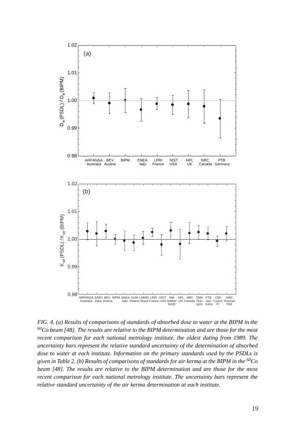
Comparisons of primary standards of absorbed dose to water have been carriedout over the past decade [29, 46, 47], whereas comparisons of air kerma primary stan-dards have a much longer history. The results of comparisons at the BIPM in terms ofabsorbed dose to water for 60Co gamma radiation are given in Ref. [48] (see
19
FIG. 4. (a) Results of comparisons of standards of absorbed dose to water at the BIPM in the60Co beam [48]. The results are relative to the BIPM determination and are those for the mostrecent comparison for each national metrology institute, the oldest dating from 1989. Theuncertainty bars represent the relative standard uncertainty of the determination of absorbeddose to water at each institute. Information on the primary standards used by the PSDLs isgiven in Table 2. (b) Results of comparisons of standards for air kerma at the BIPM in the 60Cobeam [48]. The results are relative to the BIPM determination and are those for the mostrecent comparison for each national metrology institute. The uncertainty bars represent therelative standard uncertainty of the air kerma determination at each institute.
Dw
(PS
DL)
/ D
w(B
IPM
)
0.98
0.99
1.00
1.01
1.02
ARPANSAAustralia
BEVAustria
BIPM ENEAItaly
LPRIFrance
NISTUSA
NPLUK
NRCCanada
PTBGermany
(a)K
air
Kai
r(P
SD
L) /
(BIP
M)
0.98
0.99
1.00
1.01
1.02
ARPANSAAustralia
BARCIndia
BEVAustria
BIPM ENEAItaly
GUMPoland
LNMRIBrazil
LPRIFrance
NISTUSA
NMiNether- lands
NPLUK
NRCCanada
OMHHun-gary
PTBGer-many
CMICzech
R.
NIIMRussian
Fed.
(b)
20
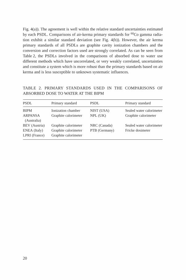
Fig. 4(a)). The agreement is well within the relative standard uncertainties estimatedby each PSDL. Comparisons of air-kerma primary standards for 60Co gamma radia-tion exhibit a similar standard deviation (see Fig. 4(b)). However, the air kermaprimary standards of all PSDLs are graphite cavity ionization chambers and theconversion and correction factors used are strongly correlated. As can be seen fromTable 2, the PSDLs involved in the comparisons of absorbed dose to water usedifferent methods which have uncorrelated, or very weakly correlated, uncertaintiesand constitute a system which is more robust than the primary standards based on airkerma and is less susceptible to unknown systematic influences.
TABLE 2. PRIMARY STANDARDS USED IN THE COMPARISONS OFABSORBED DOSE TO WATER AT THE BIPM
PSDL Primary standard PSDL Primary standard
BIPM Ionization chamber NIST (USA) Sealed water calorimeterARPANSA Graphite calorimeter NPL (UK) Graphite calorimeter
(Australia)BEV (Austria) Graphite calorimeter NRC (Canada) Sealed water calorimeterENEA (Italy) Graphite calorimeter PTB (Germany) Fricke dosimeterLPRI (France) Graphite calorimeter
21
3. ND,w BASED FORMALISM
The formalism for the determination of absorbed dose to water in high energyphoton and electron beams using an ionization chamber or a dosimeter calibrated interms of absorbed dose to water in a 60Co beam has been given in detail byHohlfeld [27]. Complementary work on this topic and extensions of the formalismhave been developed by Andreo [20] and Rogers [28]. The procedure for the deter-mination of absorbed dose to water based on standards of absorbed dose to water hasbeen implemented in the national dosimetry recommendations [49–51]. It was alsoincluded in the IAEA Code of Practice for plane-parallel ionization chambers [21].
3.1. FORMALISM
The absorbed dose to water at the reference depth zref in water for a referencebeam of quality Qo and in the absence of the chamber is given by
Dw,Qo= MQo
ND,w,Qo(1)
where MQois the reading of the dosimeter under the reference conditions used in the
standards laboratory and ND,w,Qois the calibration factor in terms of absorbed dose to
water of the dosimeter obtained from a standards laboratory. In most clinicalsituations the measurement conditions do not match the reference conditions used inthe standards laboratory. This may affect the response of the dosimeter and it is thennecessary to differentiate between the reference conditions used in the standardslaboratory and the clinical measurement conditions.
3.1.1. Reference conditions
The calibration factor for an ionization chamber irradiated under reference con-ditions is the ratio of the conventional true value of the quantity to be measured to theindicated value.8 Reference conditions are described by a set of values of influence
8 The conventional true value of a quantity is the value attributed to a particular quantityand accepted, sometimes by convention, as having an uncertainty appropriate for a given pur-pose. The conventional true value is sometimes called assigned value, best estimate of thevalue, conventional value or reference value [52]. At a given laboratory or hospital, the valuerealized by a reference standard may be taken as a conventional true value and, frequently, themean of a number of results of measurements of a quantity is used to establish a conventionaltrue value.
22
quantities for which the calibration factor is valid without further correction factors.The reference conditions for calibrations in terms of absorbed dose to water are, forexample, the geometrical arrangement (distance and depth), the field size, the mate-rial and dimensions of the irradiated phantom, and the ambient temperature, pressureand relative humidity.
3.1.2. Influence quantities
Influence quantities are defined as quantities that are not the subject of the mea-surement, but yet influence the quantity under measurement. They may be of differentnature as, for example, pressure, temperature and polarization voltage; they may arisefrom the dosimeter (e.g. ageing, zero drift, warm-up); or may be quantities related tothe radiation field (e.g. beam quality, dose rate, field size, depth in a phantom).
In calibrating an ionization chamber or a dosimeter, as many influence quanti-ties as practicable are kept under control. However, many influence quantities cannotbe controlled, for example air pressure and humidity, and dose rate in 60Co gammaradiation. It is possible to correct for the effect of these influence quantities byapplying appropriate factors. Assuming that influence quantities act independentlyfrom each other, a product of correction factors can be applied, Π ki, where eachcorrection factor ki is related to one influence quantity only. The independence of kiholds for the common corrections for pressure and temperature, polarity, collectionefficiency, etc., which are dealt with in Section 4.
A departure from the reference beam quality Qo used to calibrate an ionizationchamber can also be treated as an influence quantity. Measurements at radiation qual-ities other than the reference quality Qo therefore require a correction factor. In thisCode of Practice this is treated explicitly by the factor kQ,Qo
which is not included inthe ki above; the correction for the radiation beam quality is described in detail below.
3.2. Correction for the radiation quality of the beam, kQ,Qo
When a dosimeter is used in a beam of quality Q different from that used in itscalibration, Qo, the absorbed dose to water is given by
Dw,Q = MQ ND,w,Qo kQ,Qo(2)
where the factor kQ,Qocorrects for the effects of the difference between the reference
beam quality Qo and the actual user quality Q, and the dosimeter reading MQ has beencorrected to the reference values of influence quantities, other than beam quality, forwhich the calibration factor is valid.
23
The beam quality correction factor kQ,Qois defined as the ratio, at the qualities
Q and Qo, of the calibration factors in terms of absorbed dose to water of the ioniza-tion chamber
(3)
The most common reference quality Qo used for the calibration of ionizationchambers is 60Co gamma radiation, in which case the symbol kQ is used in this Codeof Practice for the beam quality correction factor. In some PSDLs high energy photonand electron beams are directly used for calibration purposes and the symbol kQ,Qo
isused in those cases.
Ideally, the beam quality correction factor should be measured directly foreach chamber at the same quality as the user beam. However, this is not achievablein most standards laboratories. Such measurements can be performed only inlaboratories with access to the appropriate beam qualities. For this reason the tech-nique is at present restricted to a few PSDLs in the world. The procedure requiresthe availability of an energy independent dosimetry system, such as a calorimeter,operating at these qualities. A related problem is the difficulty in reproducing in astandards laboratory beam qualities identical to those produced by clinicalaccelerators [53].
When no experimental data are available, or it is difficult to measure kQ,Qodirectly for realistic clinical beams, in many cases the correction factors can becalculated theoretically. Where Bragg–Gray theory can be applied, an expression forkQ,Qo
can be derived comparing Eq. (2) with the ND,air formalism used in the IAEACodes of Practice [17, 21] and other dosimetry protocols. A general expression forkQ,Qo
has been given in Refs [20, 54]
(4)
which is valid for all types of high energy beams and includes ratios, at the qualitiesQ and Qo, of Spencer–Attix water/air stopping-power ratios, sw,air, of the mean energyexpended in air per ion pair formed, Wair,
9 and of the perturbation factors pQ. The
( )( )
( )( )
air air
air airo
ooo
w, Q Q QQ,Q
w, QQQ
s W pk =
s W p
= =o
o o o
w,Q QD,w,QQ,Q
D,w,Q w,Q Q
D /MNk
N D /M
9 It should be noticed that Wair, as well as sw,air, should be averaged over the completespectra of particles present. This is an important limitation in the case of heavy charged parti-cles, where the determination of all possible particle spectra is a considerable undertaking.
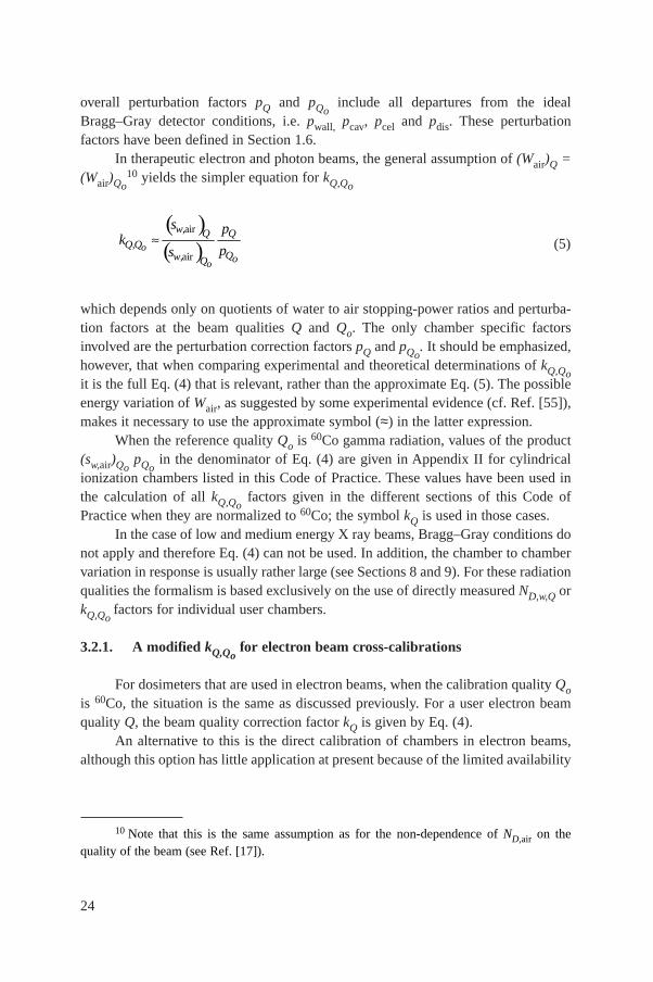
24
overall perturbation factors pQ and pQoinclude all departures from the ideal
Bragg–Gray detector conditions, i.e. pwall, pcav, pcel and pdis. These perturbationfactors have been defined in Section 1.6.
In therapeutic electron and photon beams, the general assumption of (Wair)Q =(Wair)Qo
10 yields the simpler equation for kQ,Qo
(5)
which depends only on quotients of water to air stopping-power ratios and perturba-tion factors at the beam qualities Q and Qo. The only chamber specific factorsinvolved are the perturbation correction factors pQ and pQo
. It should be emphasized,however, that when comparing experimental and theoretical determinations of kQ,Qoit is the full Eq. (4) that is relevant, rather than the approximate Eq. (5). The possibleenergy variation of Wair, as suggested by some experimental evidence (cf. Ref. [55]),makes it necessary to use the approximate symbol (≈) in the latter expression.
When the reference quality Qo is 60Co gamma radiation, values of the product(sw,air)Qo
pQoin the denominator of Eq. (4) are given in Appendix II for cylindrical
ionization chambers listed in this Code of Practice. These values have been used inthe calculation of all kQ,Qo
factors given in the different sections of this Code ofPractice when they are normalized to 60Co; the symbol kQ is used in those cases.
In the case of low and medium energy X ray beams, Bragg–Gray conditions donot apply and therefore Eq. (4) can not be used. In addition, the chamber to chambervariation in response is usually rather large (see Sections 8 and 9). For these radiationqualities the formalism is based exclusively on the use of directly measured ND,w,Q orkQ,Qo
factors for individual user chambers.
3.2.1. A modified kQ,Qofor electron beam cross-calibrations
For dosimeters that are used in electron beams, when the calibration quality Qois 60Co, the situation is the same as discussed previously. For a user electron beamquality Q, the beam quality correction factor kQ is given by Eq. (4).
An alternative to this is the direct calibration of chambers in electron beams,although this option has little application at present because of the limited availability
( )( )
air
airo
o
w, Q QQ,Q
Qw, oQ
s pk
psª
10 Note that this is the same assumption as for the non-dependence of ND,air on thequality of the beam (see Ref. [17]).
25
of such calibrations. However, the ongoing development of electron beam primarystandards will enable calibration at a series of electron beam qualities. From thesecalibration factors, a series of measured kQ,Qo
factors may be derived following theprocedure given in Section 7.5.2 (the same procedure is used for chambers calibrateddirectly in high energy photons and in low and medium energy X rays).
A third possibility, which in the absence of direct calibration in electron beamsis the preferred choice, is the cross-calibration of a plane-parallel chamber against acalibrated cylindrical chamber in a high energy electron beam of quality Qcross. Thefactors kQ,Qcross
, which allow the subsequent use of this chamber in an electron beamof quality Q, are non-trivial because the cross-calibration quality Qcross is not uniqueand so for each chamber type a two dimensional table of kQ,Qcross
factors is required.However, it is possible to present the required data in a single table by intro-
ducing an arbitrary electron beam quality Qint which acts as an intermediate betweenthe cross-calibration quality Qcross and the user quality Q (no measurements are madeat Qint, it is a tool to simplify the presentation of the data). The required kQ,Qcrossfactor is evaluated as the ratio of the factors kQ,Qint
and kQcross,Qint:
(6)
The factor (kQcross,Qint)–1 corrects the actual chamber calibration factor
ND,w,Qcrossinto a calibration factor which applies at the intermediate quality Qint. The
factor kQ,Qintcorrects this latter calibration factor into one which applies at Q so that
the general Eq. (2) for Dw,Q can be applied.The expressions for kQ,Qint
and kQcross,Qintfollow from Eq. (5), from which it is
clear that the stopping-power ratios and perturbation factors at Qint will cancel inEq. (6). Thus the value chosen for Qint is arbitrary and in this Code of Practice ischosen as R50 = 7.5 g/cm2, where R50 is the beam quality index in electron beams (seeSection 7). Values for kQ,Qint
and kQcross,Qintcalculated on this basis are given in
Table 19 of Section 7.6.1 for a series of chamber types.The data of Table 19 highlight another advantage of this approach. For a given
Q and Qcross, the value for kQcross,Qintis the same for all well guarded plane-parallel
chamber types. For cylindrical chamber types it depends only on the chamber radiusrcyl. The chosen value for Qint minimizes the differences for cylindrical chambersof different rcyl over the range of beam qualities for which cylindrical chambers areused. This value for Qint (R50 = 7.5 g/cm2) is also consistent with Ref. [51], sothat the same measured or calculated values for kQ,Qint
and kQcross,Qintmay be
used in Eq. (6).Note that the above method may also be used for plane-parallel or cylindrical
chambers calibrated at a standards laboratory at a single electron beam quality Qo.
int
intcross
cross
Q,QQ,Q
Q ,Q
kk =
k
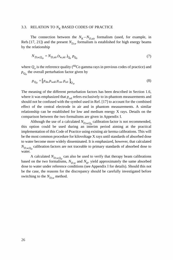
26
3.3. RELATION TO NK BASED CODES OF PRACTICE
The connection between the NK – ND,air formalism (used, for example, inRefs [17, 21]) and the present ND,w formalism is established for high energy beamsby the relationship
(7)
where Qo is the reference quality (60Co gamma rays in previous codes of practice) andpQo
the overall perturbation factor given by
(8)
The meaning of the different perturbation factors has been described in Section 1.6,where it was emphasized that pcel refers exclusively to in-phantom measurements andshould not be confused with the symbol used in Ref. [17] to account for the combinedeffect of the central electrode in air and in phantom measurements. A similarrelationship can be established for low and medium energy X rays. Details on thecomparison between the two formalisms are given in Appendix I.
Although the use of a calculated ND,w,Qocalibration factor is not recommended,
this option could be used during an interim period aiming at the practicalimplementation of this Code of Practice using existing air kerma calibrations. This willbe the most common procedure for kilovoltage X rays until standards of absorbed doseto water become more widely disseminated. It is emphasized, however, that calculatedND,w,Qo
calibration factors are not traceable to primary standards of absorbed dose towater.
A calculated ND,w,Qocan also be used to verify that therapy beam calibrations
based on the two formalisms, ND,w and NK, yield approximately the same absorbeddose to water under reference conditions (see Appendix I for details). Should this notbe the case, the reasons for the discrepancy should be carefully investigated beforeswitching to the ND,w method.
[ ]dis wall cav celQ Qo op = p p p p
air air Q QD,w,Q D, w,o o oN = N (s ) p
27
4. IMPLEMENTATION
4.1. GENERAL
Efforts in PSDLs have concentrated on providing calibrations in terms ofabsorbed dose to water of ionization chambers in 60Co gamma ray beams, and to alesser extent in high energy photon and electron beams [46, 56–59]. Depending onthe standards laboratory, users may be provided with ND,w,Qo
calibrations accordingto different options. These options are clarified here in order to avoid the incorrect useof this Code of Practice.
(a) The first approach is to provide users with a calibration factor at a referencebeam quality Qo, usually 60Co. For additional qualities the calibration at the ref-erence quality is supplied together with directly measured beam quality correc-tion factors kQ,Qo
for that particular chamber at specific beam qualities Q. Onlylaboratories having radiation sources and standards operating at different beamqualities can provide directly measured values of kQ,Qo
for these qualities. Themain advantage of this approach is that the individual chamber response in awater phantom irradiated by various beam types and qualities is intrinsicallytaken into account. A possible limitation, common to option (b) below, residesin the difference between the beam qualities used at the standards laboratoryand at the user facility, which is of special relevance for high energy beams (cf.Ref. [53]) and whose influence is still the subject of studies at some PSDLs.
(b) An alternative approach, which is in practical terms identical to the onedescribed above and differs only in the presentation of the data, is to provide aseries of ND,w,Q calibrations of the user ionization chamber at beam qualities Q.There is, however, an advantage in presenting the data by normalizing allcalibration factors to a single calibration factor ND,w,Qo
, together with directlymeasured values of kQ,Qo
. Once directly measured values of kQ,Qofor a partic-
ular chamber have been obtained, it may not be necessary for the user to recal-ibrate the chamber at all qualities Q, but only at the single reference quality Qo.The quality dependence of that chamber can be verified less often by calibra-tion at all qualities.11 Furthermore, this single reference quality calibration doesnot need to be performed at the same laboratory where the kQ,Qo
values weremeasured (usually a PSDL).
(c) In the third approach users can be provided with a ND,w,Qocalibration factor for
the ionization chamber, most commonly at the reference quality 60Co, and
11 See Section 4.3 for recommendations on the frequency of dosimeter calibrations.
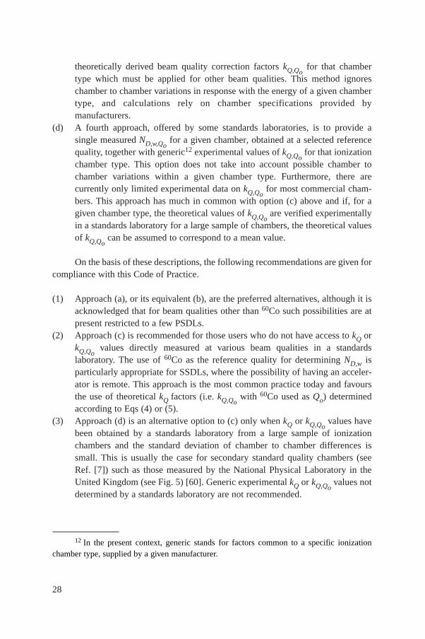
28
theoretically derived beam quality correction factors kQ,Qofor that chamber
type which must be applied for other beam qualities. This method ignoreschamber to chamber variations in response with the energy of a given chambertype, and calculations rely on chamber specifications provided bymanufacturers.
(d) A fourth approach, offered by some standards laboratories, is to provide asingle measured ND,w,Qo
for a given chamber, obtained at a selected referencequality, together with generic12 experimental values of kQ,Qo
for that ionizationchamber type. This option does not take into account possible chamber tochamber variations within a given chamber type. Furthermore, there arecurrently only limited experimental data on kQ,Qo
for most commercial cham-bers. This approach has much in common with option (c) above and if, for agiven chamber type, the theoretical values of kQ,Qo
are verified experimentallyin a standards laboratory for a large sample of chambers, the theoretical valuesof kQ,Qo
can be assumed to correspond to a mean value.
On the basis of these descriptions, the following recommendations are given forcompliance with this Code of Practice.
(1) Approach (a), or its equivalent (b), are the preferred alternatives, although it isacknowledged that for beam qualities other than 60Co such possibilities are atpresent restricted to a few PSDLs.
(2) Approach (c) is recommended for those users who do not have access to kQ orkQ,Qo
values directly measured at various beam qualities in a standardslaboratory. The use of 60Co as the reference quality for determining ND,w isparticularly appropriate for SSDLs, where the possibility of having an acceler-ator is remote. This approach is the most common practice today and favoursthe use of theoretical kQ factors (i.e. kQ,Qo
with 60Co used as Qo) determinedaccording to Eqs (4) or (5).
(3) Approach (d) is an alternative option to (c) only when kQ or kQ,Qovalues have
been obtained by a standards laboratory from a large sample of ionizationchambers and the standard deviation of chamber to chamber differences issmall. This is usually the case for secondary standard quality chambers (seeRef. [7]) such as those measured by the National Physical Laboratory in theUnited Kingdom (see Fig. 5) [60]. Generic experimental kQ or kQ,Qo
values notdetermined by a standards laboratory are not recommended.
12 In the present context, generic stands for factors common to a specific ionizationchamber type, supplied by a given manufacturer.
29
(4) Low and medium energy X ray dosimetry must be based on approaches (a) or(b) with the range of values of Q chosen to be as similar as possible to thequalities of the beams that will be used clinically.
(5) As long as there are restricted possibilities for establishing experimental ND,w,Qfactors by standards laboratories in proton and heavy ion beams, the theoreticalapproach (c) is the only recommendation to be used for such beams.
4.2. EQUIPMENT
Only ionometric measurements are considered in this Code of Practice forreference dosimetry. The requirements on equipment follow closely those inRefs [17, 21], as well as IEC Standard 60731 [7] for dosimeters with ionizationchambers. The use of these documents, although developed for photon and electronradiation, can be extended to the other types of radiation fields included in this Code
FIG. 5. Mean values of kQ at various photon beam qualities measured at the National PhysicalLaboratory (NPL) in the UK for secondary standard ionization chambers of the type NE 2561(open circles) and NE 2611 (filled circles) [60]. The solid line is a sigmoidal fit to the experi-mental data. The uncertainty bars represent chamber to chamber variations, determined as thestandard deviations of samples of 13 NE 2561 (upper half) and 11 NE 2611 (lower half) cham-bers. The values of kQ are normalized to a TPR20,10 of 0.568 (60Co beam at the NPL). Calculatedvalues of kQ for these chambers given in Table 14 are included for comparison (triangles); notethat the calculated values do not distinguish between the two types of chamber.
Photon beam quality, Q (TPR 20,10)
0.55 0.60 0.65 0.70 0.75 0.80
kQ
0.96
0.97
0.98
0.99
1.00
30
of Practice. The present section provides only general requirements on equipment;specific details on instrumentation that apply to each radiation type will be discussedin the relevant section.
An ionometric dosimeter system for radiotherapy contains the followingcomponents:
(a) One or more ionization chamber assemblies, which include the electrical fittingand any permanently attached cable, intended for different purposes (e.g. dif-ferent radiation qualities);
(b) A measuring assembly (electrometer), often separately calibrated in terms ofcharge or current per scale division;
(c) One or more phantoms with waterproof sleeves;(d) The dosimeter system should also include one or more stability check devices.
4.2.1. Ionization chambers
A cylindrical ionization chamber type may be used for the calibration of radio-therapy beams of medium energy X rays above 80 kV and an HVL of 2 mmaluminium, 6OCo gamma radiation, high energy photon beams, electron beams withenergy above 10 MeV approximately, and therapeutic proton and heavy ion beams.This type of chamber is very convenient for measurements at these radiation qualitiesas it is robust and simple to use for measurements in a water phantom. The chambercavity volume should be between about 0.1 and 1 cm3. This size range is a compro-mise between the need for sufficient sensitivity and the ability to measure dose at apoint. These requirements are met in cylindrical chambers with an air cavity ofinternal diameter not greater than around 7 mm and an internal length not greater thanaround 25 mm. In use, the chamber must be aligned in such a way that the radiationfluence is approximately uniform over the cross-section of the chamber cavity. Thecavity length therefore sets a lower limit on the size of the field in which measure-ments may be made.
The construction of the chamber should be as homogeneous as possible, but itis recognized that for technical reasons the central electrode is likely to be of amaterial different from that of the walls. Indeed the choice of materials may play animportant role in ensuring that the energy response of the chamber does not varyconsiderably. It is also necessary for the air cavity not to be sealed; it should bedesigned so that it will equilibrate rapidly with the ambient temperature and airpressure.
In choosing a cylindrical ionization chamber the user should pay attention as towhether it is to be used as a reference instrument (calibrated at a standards laboratoryand used for beam calibration in the user beam) or as a field instrument (cross-calibrated against a reference chamber and normally used for routine measurements).
31
Graphite walled ionization chambers usually have better long term stability and moreuniform response than plastic walled chambers; however, the latter are more robustand therefore more suitable for routine measurements. Humid air may, on the otherhand, affect the chamber response, especially for chambers with Nylon or A-150walls [61]. As an ionization chamber is an instrument of high precision, attentionshould be paid to acquiring a chamber type whose performance has been sufficientlytested in radiotherapy beams. Characteristics of certain cylindrical ionization cham-bers are given in Table 3.
The use of plane-parallel ionization chambers in high energy electron andphoton beams has been described in detail in Ref. [21]. Plane-parallel chambers arerecommended to be used at all electron energies, and below 10 MeV their use ismandatory. For photon beams, they are suitable for reference dosimetry measure-ments only when a calibration in terms of absorbed dose to water is available at theuser quality. They are also suitable for reference dosimetry for proton and heavy ionbeams, especially for beams having narrow SOBP. The chamber should preferablybe designed for use in water and the construction should be as homogeneous andwater equivalent as possible. It is especially important to be aware of backscattereffects from the rear wall of the chamber. Chambers designed for measurements insolid phantoms should accordingly be as phantom equivalent as possible. Somechambers have, however, a design that includes several materials, resulting in asignificant departure from homogeneity. In these cases there is no simple rule for theselection of chamber type and phantom material.
One of the main advantages of plane-parallel chambers for electron beamdosimetry is the possibility of minimizing scattering perturbation effects. Plane-parallel ionization chambers may be designed so that the chamber samples theelectron fluence incident through the front window, the contribution of electronsentering through the side walls being negligible. This design justifies taking theeffective point of measurement of the chamber, Peff, to be on the inner surface of theentrance window, at the centre of the window for all beam qualities and depths. Forpractical purposes it is therefore convenient to choose the reference point of thechamber at the same position. In order to fulfil, within a reasonable approximation,the requirements concerning scattering perturbation effects and Peff, plane-parallelchambers must have a ‘pancake’ or disc shaped cavity in which the ratio of cavitydiameter to the cavity height should be large (preferably five or more). Furthermore,the diameter of the collecting electrode should not exceed 20 mm in order to reducethe influence of radial non-uniformities of the beam profile. The cavity height shouldnot exceed 2 mm, and the collecting electrode should be surrounded by a guard elec-trode having a width not smaller than 1.5 times the cavity height. In addition, thethickness of the front window should be restricted to 0.1 g/cm2 (or 1 mm of PMMA)at most, to make measurements at shallow depths possible. It is also necessary forthe air cavity to be vented so that it will equilibrate rapidly with the ambient
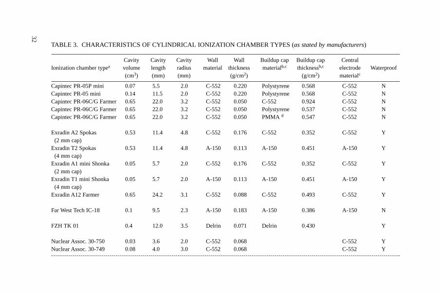
32
TABLE 3. CHARACTERISTICS OF CYLINDRICAL IONIZATION CHAMBER TYPES (as stated by manufacturers)
Cavity Cavity Cavity Wall Wall Buildup cap Buildup cap CentralIonization chamber typea volume length radius material thickness materialb,c thicknessb,c electrode Waterproof
(cm3) (mm) (mm) (g/cm2) (g/cm2) materialc
Capintec PR-05P mini 0.07 5.5 2.0 C-552 0.220 Polystyrene 0.568 C-552 NCapintec PR-05 mini 0.14 11.5 2.0 C-552 0.220 Polystyrene 0.568 C-552 NCapintec PR-06C/G Farmer 0.65 22.0 3.2 C-552 0.050 C-552 0.924 C-552 NCapintec PR-06C/G Farmer 0.65 22.0 3.2 C-552 0.050 Polystyrene 0.537 C-552 NCapintec PR-06C/G Farmer 0.65 22.0 3.2 C-552 0.050 PMMA d 0.547 C-552 N
Exradin A2 Spokas 0.53 11.4 4.8 C-552 0.176 C-552 0.352 C-552 Y(2 mm cap)
Exradin T2 Spokas 0.53 11.4 4.8 A-150 0.113 A-150 0.451 A-150 Y(4 mm cap)
Exradin A1 mini Shonka 0.05 5.7 2.0 C-552 0.176 C-552 0.352 C-552 Y(2 mm cap)
Exradin T1 mini Shonka 0.05 5.7 2.0 A-150 0.113 A-150 0.451 A-150 Y(4 mm cap)
Exradin A12 Farmer 0.65 24.2 3.1 C-552 0.088 C-552 0.493 C-552 Y
Far West Tech IC-18 0.1 9.5 2.3 A-150 0.183 A-150 0.386 A-150 N
FZH TK 01 0.4 12.0 3.5 Delrin 0.071 Delrin 0.430 Y
Nuclear Assoc. 30-750 0.03 3.6 2.0 C-552 0.068 C-552 YNuclear Assoc. 30-749 0.08 4.0 3.0 C-552 0.068 C-552 Y
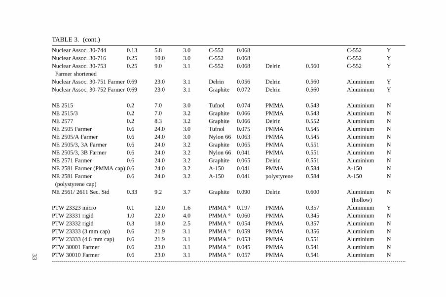
33
TABLE 3. (cont.)
Nuclear Assoc. 30-744 0.13 5.8 3.0 C-552 0.068 C-552 YNuclear Assoc. 30-716 0.25 10.0 3.0 C-552 0.068 C-552 YNuclear Assoc. 30-753 0.25 9.0 3.1 C-552 0.068 Delrin 0.560 C-552 Y
Farmer shortenedNuclear Assoc. 30-751 Farmer 0.69 23.0 3.1 Delrin 0.056 Delrin 0.560 Aluminium YNuclear Assoc. 30-752 Farmer 0.69 23.0 3.1 Graphite 0.072 Delrin 0.560 Aluminium Y
NE 2515 0.2 7.0 3.0 Tufnol 0.074 PMMA 0.543 Aluminium NNE 2515/3 0.2 7.0 3.2 Graphite 0.066 PMMA 0.543 Aluminium NNE 2577 0.2 8.3 3.2 Graphite 0.066 Delrin 0.552 Aluminium NNE 2505 Farmer 0.6 24.0 3.0 Tufnol 0.075 PMMA 0.545 Aluminium NNE 2505/A Farmer 0.6 24.0 3.0 Nylon 66 0.063 PMMA 0.545 Aluminium NNE 2505/3, 3A Farmer 0.6 24.0 3.2 Graphite 0.065 PMMA 0.551 Aluminium NNE 2505/3, 3B Farmer 0.6 24.0 3.2 Nylon 66 0.041 PMMA 0.551 Aluminium NNE 2571 Farmer 0.6 24.0 3.2 Graphite 0.065 Delrin 0.551 Aluminium NNE 2581 Farmer (PMMA cap) 0.6 24.0 3.2 A-150 0.041 PMMA 0.584 A-150 NNE 2581 Farmer 0.6 24.0 3.2 A-150 0.041 polystyrene 0.584 A-150 N
(polystyrene cap)NE 2561/ 2611 Sec. Std 0.33 9.2 3.7 Graphite 0.090 Delrin 0.600 Aluminium N
(hollow)PTW 23323 micro 0.1 12.0 1.6 PMMA e 0.197 PMMA 0.357 Aluminium YPTW 23331 rigid 1.0 22.0 4.0 PMMA e 0.060 PMMA 0.345 Aluminium NPTW 23332 rigid 0.3 18.0 2.5 PMMA e 0.054 PMMA 0.357 Aluminium NPTW 23333 (3 mm cap) 0.6 21.9 3.1 PMMA e 0.059 PMMA 0.356 Aluminium NPTW 23333 (4.6 mm cap) 0.6 21.9 3.1 PMMA e 0.053 PMMA 0.551 Aluminium NPTW 30001 Farmer 0.6 23.0 3.1 PMMA e 0.045 PMMA 0.541 Aluminium NPTW 30010 Farmer 0.6 23.0 3.1 PMMA e 0.057 PMMA 0.541 Aluminium N
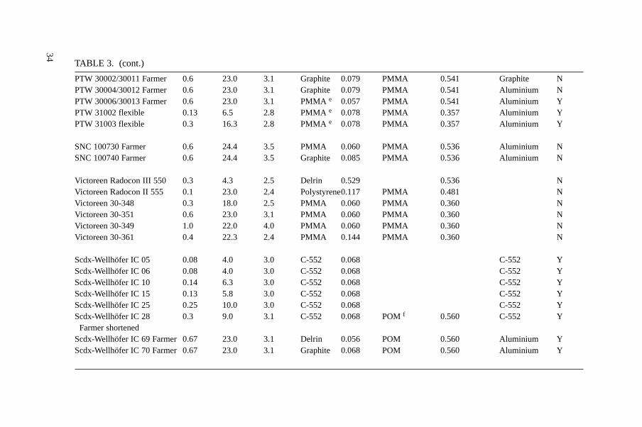
34
TABLE 3. (cont.)
PTW 30002/30011 Farmer 0.6 23.0 3.1 Graphite 0.079 PMMA 0.541 Graphite NPTW 30004/30012 Farmer 0.6 23.0 3.1 Graphite 0.079 PMMA 0.541 Aluminium NPTW 30006/30013 Farmer 0.6 23.0 3.1 PMMA e 0.057 PMMA 0.541 Aluminium YPTW 31002 flexible 0.13 6.5 2.8 PMMA e 0.078 PMMA 0.357 Aluminium YPTW 31003 flexible 0.3 16.3 2.8 PMMA e 0.078 PMMA 0.357 Aluminium Y
SNC 100730 Farmer 0.6 24.4 3.5 PMMA 0.060 PMMA 0.536 Aluminium NSNC 100740 Farmer 0.6 24.4 3.5 Graphite 0.085 PMMA 0.536 Aluminium N
Victoreen Radocon III 550 0.3 4.3 2.5 Delrin 0.529 0.536 NVictoreen Radocon II 555 0.1 23.0 2.4 Polystyrene0.117 PMMA 0.481 NVictoreen 30-348 0.3 18.0 2.5 PMMA 0.060 PMMA 0.360 NVictoreen 30-351 0.6 23.0 3.1 PMMA 0.060 PMMA 0.360 NVictoreen 30-349 1.0 22.0 4.0 PMMA 0.060 PMMA 0.360 NVictoreen 30-361 0.4 22.3 2.4 PMMA 0.144 PMMA 0.360 N
Scdx-Wellhöfer IC 05 0.08 4.0 3.0 C-552 0.068 C-552 YScdx-Wellhöfer IC 06 0.08 4.0 3.0 C-552 0.068 C-552 YScdx-Wellhöfer IC 10 0.14 6.3 3.0 C-552 0.068 C-552 YScdx-Wellhöfer IC 15 0.13 5.8 3.0 C-552 0.068 C-552 YScdx-Wellhöfer IC 25 0.25 10.0 3.0 C-552 0.068 C-552 YScdx-Wellhöfer IC 28 0.3 9.0 3.1 C-552 0.068 POM f 0.560 C-552 Y
Farmer shortenedScdx-Wellhöfer IC 69 Farmer 0.67 23.0 3.1 Delrin 0.056 POM 0.560 Aluminium YScdx-Wellhöfer IC 70 Farmer 0.67 23.0 3.1 Graphite 0.068 POM 0.560 Aluminium Y
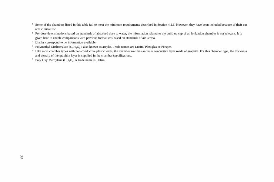
35
a Some of the chambers listed in this table fail to meet the minimum requirements described in Section 4.2.1. However, they have been included because of their cur-rent clinical use.
b For dose determinations based on standards of absorbed dose to water, the information related to the build up cap of an ionization chamber is not relevant. It isgiven here to enable comparisons with previous formalisms based on standards of air kerma.
c Blanks correspond to no information available.d Polymethyl Methacrylate (C5H8O2), also known as acrylic. Trade names are Lucite, Plexiglas or Perspex.e Like most chamber types with non-conductive plastic walls, the chamber wall has an inner conductive layer made of graphite. For this chamber type, the thickness
and density of the graphite layer is supplied in the chamber specifications.f Poly Oxy Methylene (CH2O). A trade name is Delrin.

36 TABLE 4. CHARACTERISTICS OF PLANE-PARALLEL CHAMBER TYPES (adapted from Ref. [21])
Ionization Window Electrode Collecting Guard ring Recommendedchamber typea Materials thickness spacing electrode width phantom material
diameter
NACP01 Graphite window, 90 mg/cm2 2 mm 10 mm 3 mm Polystyrene(Scanditronix) graphited rexolite electrode, 0.5 mm GraphiteCalcam-1 graphite body (back wall), Water (with water-(Dosetek) rexolite housing proof housing)
NACP02 Mylar foil and graphite 104 mg/cm2 2 mm 10 mm 3 mm Water,(Scanditronix) window, graphited rexolite 0.6 mm PMMACalcam-2 electrode, graphite body (Dosetek) (back wall), rexolite housing
Markus chamber Graphited polyethylene foil 102 mg/cm2 2 mm 5.3 mm 0.2 mm Water,PTW 23343 window, graphited polystyrene 0.9 mm PMMANA 30-329 collector, PMMA body, (incl. cap)NE 2534 PMMA capScdx-Wellhöfer Window and body C-552, 176 mg/cm2 0.5 mm 10 mm 3.5 mm Water
PPC 05 graphited (PEEKb) electrode 1 mm
Holt chamber Graphited polystyrene wall and 416 mg/cm2 2 mm 25 mm 5 mm Polystyrene(Memorial) electrode, polystyrene body 4 mm (phantom integr.)NA 30-404
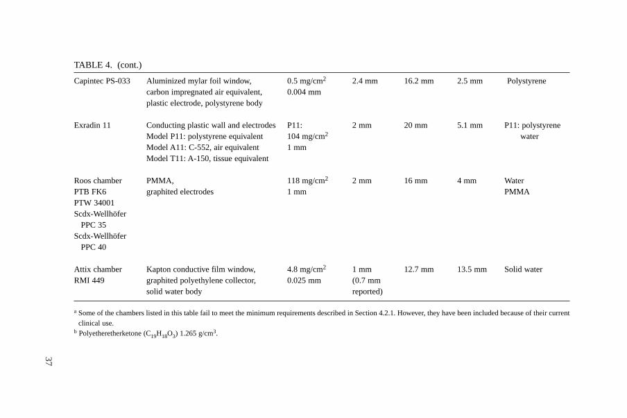
37
TABLE 4. (cont.)
Capintec PS-033 Aluminized mylar foil window, 0.5 mg/cm2 2.4 mm 16.2 mm 2.5 mm Polystyrenecarbon impregnated air equivalent, 0.004 mmplastic electrode, polystyrene body
Exradin 11 Conducting plastic wall and electrodes P11: 2 mm 20 mm 5.1 mm P11: polystyreneModel P11: polystyrene equivalent 104 mg/cm2 waterModel A11: C-552, air equivalent 1 mmModel T11: A-150, tissue equivalent
Roos chamber PMMA, 118 mg/cm2 2 mm 16 mm 4 mm WaterPTB FK6 graphited electrodes 1 mm PMMAPTW 34001Scdx-Wellhöfer
PPC 35Scdx-Wellhöfer
PPC 40
Attix chamber Kapton conductive film window, 4.8 mg/cm2 1 mm 12.7 mm 13.5 mm Solid waterRMI 449 graphited polyethylene collector, 0.025 mm (0.7 mm
solid water body reported)
a Some of the chambers listed in this table fail to meet the minimum requirements described in Section 4.2.1. However, they have been included because of their currentclinical use.
b Polyetheretherketone (C19H18O3) 1.265 g/cm3.
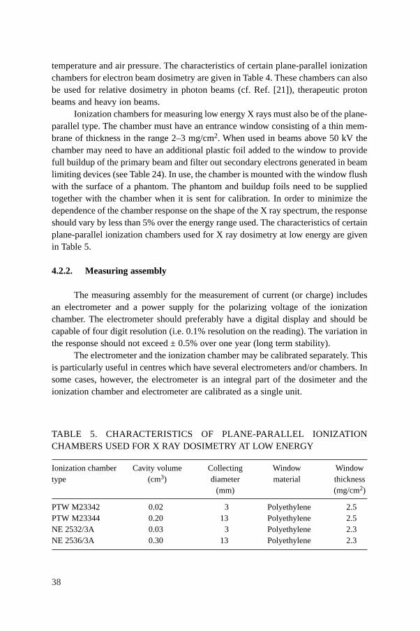
38
temperature and air pressure. The characteristics of certain plane-parallel ionizationchambers for electron beam dosimetry are given in Table 4. These chambers can alsobe used for relative dosimetry in photon beams (cf. Ref. [21]), therapeutic protonbeams and heavy ion beams.
Ionization chambers for measuring low energy X rays must also be of the plane-parallel type. The chamber must have an entrance window consisting of a thin mem-brane of thickness in the range 2–3 mg/cm2. When used in beams above 50 kV thechamber may need to have an additional plastic foil added to the window to providefull buildup of the primary beam and filter out secondary electrons generated in beamlimiting devices (see Table 24). In use, the chamber is mounted with the window flushwith the surface of a phantom. The phantom and buildup foils need to be suppliedtogether with the chamber when it is sent for calibration. In order to minimize thedependence of the chamber response on the shape of the X ray spectrum, the responseshould vary by less than 5% over the energy range used. The characteristics of certainplane-parallel ionization chambers used for X ray dosimetry at low energy are givenin Table 5.
4.2.2. Measuring assembly
The measuring assembly for the measurement of current (or charge) includesan electrometer and a power supply for the polarizing voltage of the ionizationchamber. The electrometer should preferably have a digital display and should becapable of four digit resolution (i.e. 0.1% resolution on the reading). The variation inthe response should not exceed ± 0.5% over one year (long term stability).
The electrometer and the ionization chamber may be calibrated separately. Thisis particularly useful in centres which have several electrometers and/or chambers. Insome cases, however, the electrometer is an integral part of the dosimeter and theionization chamber and electrometer are calibrated as a single unit.
TABLE 5. CHARACTERISTICS OF PLANE-PARALLEL IONIZATIONCHAMBERS USED FOR X RAY DOSIMETRY AT LOW ENERGY
Ionization chamber Cavity volume Collecting Window Windowtype (cm3) diameter material thickness
(mm) (mg/cm2)
PTW M23342 0.02 3 Polyethylene 2.5PTW M23344 0.20 13 Polyethylene 2.5NE 2532/3A 0.03 3 Polyethylene 2.3NE 2536/3A 0.30 13 Polyethylene 2.3
39
It should be possible to reverse the polarity of the polarizing voltage, so that thepolarity effect of the ionization chamber may be determined, and to vary the voltagein order to determine the collection efficiency as described in Section 4.4.3.4.
4.2.3. Phantoms
Water is recommended in the IAEA Codes of Practice [17, 21] as the referencemedium for measurements of absorbed dose for both photon and electron beams, andthe same is recommended in this Code of Practice. The phantom should extend to atleast 5 cm beyond all four sides of the largest field size employed at the depth ofmeasurement. There should also be a margin of at least 5 g/cm2 beyond the maximumdepth of measurement except for medium energy X rays in which case it shouldextend to at least 10 g/cm2.
Solid phantoms in slab form such as polystyrene, PMMA, and certain water-equivalent plastics such as solid water, plastic water, virtual water, etc. (seeRefs [62, 63]) may be used for low energy electron beam dosimetry (below approxi-mately 10 MeV, see Section 7.8) and are generally required for low energy X rays.Nevertheless, the dose determination must always be referred to the absorbed dose towater at the reference depth in a homogeneous water phantom. Ideally, the phantommaterial should be water equivalent; that is, have the same absorption and scatterproperties as water. The elemental composition (in fraction by weight), nominaldensity and mean atomic number of some common phantom materials used as watersubstitutes are given in Table 6.
In spite of their increasing popularity, the use of plastic phantoms is stronglydiscouraged for reference measurements (except for low energy X rays), as in generalthey are responsible for the largest discrepancies in the determination of absorbeddose for most beam types. This is mainly due to density variations between differentbatches and to the approximate nature of the procedures for scaling depths andabsorbed dose (or fluence) from plastic to water. The density of the plastic should bemeasured for the batch of plastic in use rather than using a nominal value for theplastic type as supplied by the manufacturer, since density differences of up to 4%have been reported (see, for example, Ref. [65]). The commissioning of plastic phan-toms in slab form should include a determination of the mean thickness and densityof each slab, as well as the variation in thickness over a single slab and an investiga-tion by radiograph for bubbles or voids in the plastic.
Although not recommended for use in reference dosimetry, plastic phantomscan be used for routine quality assurance measurements, provided the relationshipbetween dosimeter readings in plastic and water has been established for the userbeam at the time of calibration. This will involve a careful comparison withmeasurements in water, which should be performed prior to the routine use of the
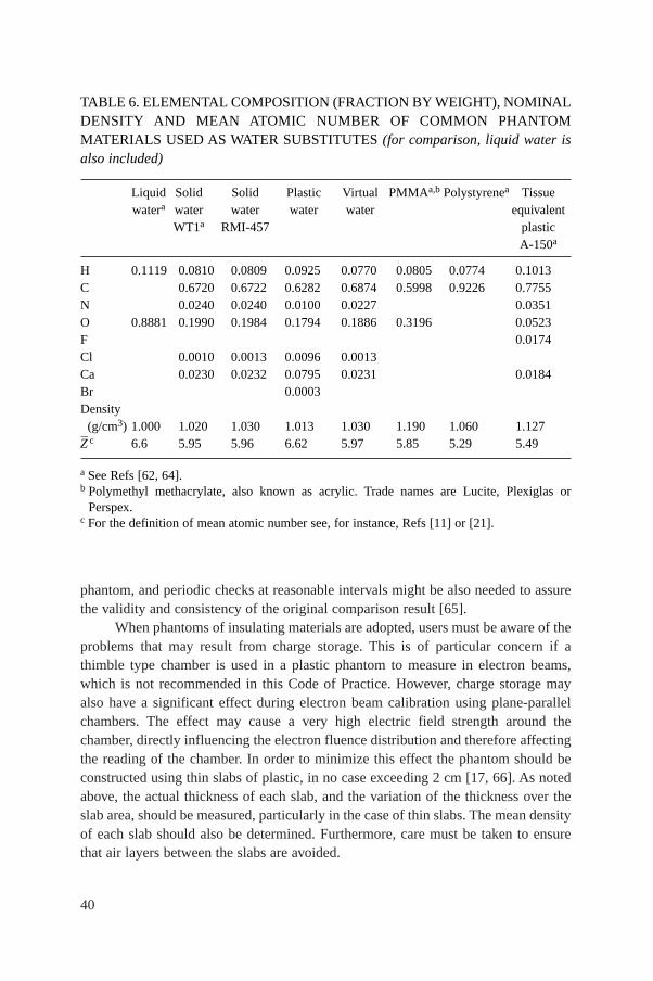
40
phantom, and periodic checks at reasonable intervals might be also needed to assurethe validity and consistency of the original comparison result [65].
When phantoms of insulating materials are adopted, users must be aware of theproblems that may result from charge storage. This is of particular concern if athimble type chamber is used in a plastic phantom to measure in electron beams,which is not recommended in this Code of Practice. However, charge storage mayalso have a significant effect during electron beam calibration using plane-parallelchambers. The effect may cause a very high electric field strength around thechamber, directly influencing the electron fluence distribution and therefore affectingthe reading of the chamber. In order to minimize this effect the phantom should beconstructed using thin slabs of plastic, in no case exceeding 2 cm [17, 66]. As notedabove, the actual thickness of each slab, and the variation of the thickness over theslab area, should be measured, particularly in the case of thin slabs. The mean densityof each slab should also be determined. Furthermore, care must be taken to ensurethat air layers between the slabs are avoided.
TABLE 6. ELEMENTAL COMPOSITION (FRACTION BY WEIGHT), NOMINALDENSITY AND MEAN ATOMIC NUMBER OF COMMON PHANTOMMATERIALS USED AS WATER SUBSTITUTES (for comparison, liquid water isalso included)
Liquid Solid Solid Plastic Virtual PMMAa,b Polystyrenea Tissuewatera water water water water equivalent
WT1a RMI-457 plasticA-150a
H 0.1119 0.0810 0.0809 0.0925 0.0770 0.0805 0.0774 0.1013C 0.6720 0.6722 0.6282 0.6874 0.5998 0.9226 0.7755N 0.0240 0.0240 0.0100 0.0227 0.0351O 0.8881 0.1990 0.1984 0.1794 0.1886 0.3196 0.0523F 0.0174Cl 0.0010 0.0013 0.0096 0.0013Ca 0.0230 0.0232 0.0795 0.0231 0.0184Br 0.0003Density
(g/cm3) 1.000 1.020 1.030 1.013 1.030 1.190 1.060 1.127Z– c 6.6 5.95 5.96 6.62 5.97 5.85 5.29 5.49
a See Refs [62, 64].b Polymethyl methacrylate, also known as acrylic. Trade names are Lucite, Plexiglas or
Perspex.c For the definition of mean atomic number see, for instance, Refs [11] or [21].
41
4.2.4. Waterproof sleeve for the chamber
Unless the ionization chamber is designed so that it can be put directly intowater, it must be used with a waterproof sleeve. The following recommendations havebeen adapted from those given in Ref. [33]. The sleeve should be made of PMMA,with a wall sufficiently thin (preferably not greater than 1.0 mm in thickness) to allowthe chamber to achieve thermal equilibrium with the water in less than 10 min. Thesleeve should be designed so as to allow the air pressure in the chamber to reachambient air pressure quickly; an air gap of 0.1–0.3 mm between the chamber and thesleeve is adequate. In order to reduce the buildup of water vapour around the chamber,a waterproof sleeve should not be left in water longer than is necessary to carry outthe measurements. Additional accuracy is gained if the same sleeve that was used forthe calibration of a chamber in the standards laboratory is also used for all subsequentmeasurements.
For ionization chambers that are waterproof, the use of a PMMA sleeve maystill be a desirable option for positioning the chamber accurately at a given depth,although this depends on the positioning equipment used. Measurements at the IAEADosimetry Laboratory with a waterproof Farmer type chamber, PTW W30006, havenot shown significant variations in ND,w when the chamber was calibrated with andwithout PMMA sleeves up to 1 mm in thickness. This chamber type may therefore becalibrated with or without a sleeve and may be used subsequently in a manner thatbest suits the conditions at the hospital. For other waterproof chamber types similarmeasurements should be conducted at a standards laboratory prior to adoption of sucha procedure.
The use of a thin rubber sheath is not recommended, especially for a referencechamber; there is a greater risk of leakage and such a sheath restricts pressureequilibration of the air in the chamber. Moreover, manufacturers usually coat theinner surface of rubber sheaths with a fine powder; this can find its way into thechamber cavity and affect the chamber response, particularly for low and mediumenergy X rays [67].
4.2.5. Positioning of ionization chambers at the reference depth
In positioning a chamber at the reference depth in water, zref (expressed ing/cm2), the perturbing effects of the chamber cavity and wall, and the waterproofsleeve or cover, must be considered. When the user quality Q is the same as thecalibration quality Qo, or when measured kQ,Qo
values are used, these effects areaccounted for in the chamber calibration and it normally suffices to position thechamber at the same depth as at calibration (an exception is when a waterproof sleeveor cover of significantly different thickness is used at chamber calibration and at the
42
user quality). This is one of the important advantages of calibrations in terms ofabsorbed dose to water.
When no direct calibration at the user quality is available, calculated values forkQ,Qo
must be used. In this case, certain perturbing effects are accounted for in thekQ,Qo
values and others must be accounted for in the positioning of the chamber.Account must also be taken of the effect of any phantom window. These considera-tions are discussed below. The term water equivalent thickness (in g/cm2) refers to theproduct of the actual thickness (in cm) and the material density (in g/cm3).
Note that in clinical use it may be more practical to position chambers at aprecisely known depth which is within a millimetre or so of the reference depth, andto correct the result to zref using the depth dose distribution of the user beam, ratherthan attempting to position a chamber to a fraction of a millimetre.
Note also that the term reference point of the chamber is used below and inthe specification of reference conditions in each section. For cylindrical chambertypes this refers to the centre of the cavity volume of the chamber on the chamberaxis13 and for plane-parallel chamber types (other than in low energy X rays) it refersto the inner surface of the entrance window, at the centre of the window. For plane-parallel chamber types used in low energy X rays, it refers to the centre of the outersurface of the chamber window (or any buildup foils used).
4.2.5.1. Chamber cavity effects
Two effects arise from the chamber cavity. The perturbation by the cavity of theelectron fluence entering the cavity is accounted for by the factor pcav included incalculated kQ,Qo
factors. However, a chamber positioned with its cavity centre at zrefdoes not sample the electron fluence present at zref in the undisturbed phantom. Thismay be accounted for either by applying a displacement correction factor pdis in thecalculation of kQ,Qo
, or by displacing the chamber by an amount which compensatesfor this effect (often referred to as the use of the effective point of measurement [17]).For plane-parallel chamber types, the chamber reference point is defined to be at theeffective point of measurement; when this is placed at zref no displacement correctionfactor pdis is required.
For cylindrical chamber types the method used depends on the radiationmodality and this is specified in the reference conditions in each section. In 60Co,high energy photon beams and proton beams, the chamber centre is positioned at zref
13 The centre of the cavity volume should be taken to be that point on the chamber axiswhich is a given distance, as stated by the manufacturer, from the tip of the chamber (measuredwithout buildup cap). For example, for the NE 2561 and NE 2611A chamber types it is 5 mmfrom the tip and for the NE 2571 Farmer type chamber it is 13 mm from the tip.
43
and values for pdis are used in the calculation of kQ,Qo. In electron beams and in heavy
ion beams, this method of positioning is not recommended because of the steep dosegradients involved, and cylindrical chambers are positioned with the centre displacedfrom zref. For electron beams the chamber centre is positioned 0.5 rcyl deeper than zref,where rcyl is the internal radius of the chamber cavity. For heavy ion beams, a shift of0.75 rcyl is recommended.
4.2.5.2. Chamber wall effects
The factor pwall included in calculated kQ,Qofactors corrects for the different
radiation response of the chamber wall material from that of the phantom material.However, pwall does not include the effect of the different attenuation of the primaryfluence by the chamber wall compared with the same thickness of phantom material.When the calibration quality Qo and the user quality Q are the same, this attenuationis accounted for in the calibration of the chamber. Even when Qo is not the same asQ, the wall attenuation in photon beams is sufficiently small that cancellation may beassumed. On the other hand, in charged particle beams, the attenuation due to thechamber wall can be significantly different from that due to the same thickness ofphantom material, and strictly, the water equivalent thickness of the chamber wallshould be taken into account when calculating where to position the chamber. Inpractice, for the wall thicknesses normally encountered the required adjustment issmall and may be neglected.
4.2.5.3. Chamber waterproofing
Waterproofing sleeves or covers are treated in a similar manner to the chamberwall; in fact, if the same (or very similar) sleeve or cover is used at calibration and in theuser beam, then it may be considered as part of the chamber wall and treated accordingly.This is the approach recommended in this Code of Practice. However, if a significantlydifferent sleeve or cover is used, the difference in the water equivalent thicknesses mustbe taken into account in positioning the chamber at zref, for all modalities.
4.2.5.4. Phantom window
For all modalities, when a horizontal beam is used, the water equivalent thick-ness of the phantom window should be taken into account. Note also that thinwindows may be subject to an outward bowing owing to the water pressure on theinner surface. This effect may occur as soon as the phantom is filled and can increasegradually over the next few hours. Any such effect increases the amount of water infront of a chamber and should also be accounted for in the positioning of the chamberat zref, particularly for medium energy X rays and low energy electron beams.
44
4.3. CALIBRATION OF IONIZATION CHAMBERS
When an ionization chamber or dosimeter is sent to a standards laboratory forcalibration, stability check measurements (using a suitable check device) should becarried out by the user before and after the calibration. This will ensure that thechamber response has not been affected by the transportation. A reference ionizationchamber should be calibrated at a reference quality Qo at intervals not exceeding twoor three years, or whenever the user suspects that the chamber has been damaged. Ifdirectly measured values of kQ,Qo
(or ND,w,Q) for the chamber have been obtained pre-viously, a recalibration to verify the quality dependence of the chamber should bemade at least every third time that the chamber is calibrated. This procedure shouldnot be repeated more than twice in succession; the chamber should be recalibrated atall qualities at least every six years. However, because of the particular susceptibilityof ionization chambers to change in energy response in low and medium energyX rays, it is preferable that chambers used for these beams are recalibrated at allrelevant qualities each time. It is the responsibility of the user to increase thefrequency of the calibrations for chambers whose long term stability has not beenverified over a period exceeding five years.
4.3.1. Calibration in a 60Co beam
Calibrations may be carried out either directly against a primary standard ofabsorbed dose to water at a PSDL or, more commonly, against a secondary standardat an SSDL. Only the latter case will be discussed here.14
It is assumed that the absorbed dose to water, Dw, is known at a depth of5 g/cm2 in a water phantom for 60Co gamma rays. This is realized at the SSDL bymeans of a calibrated cavity ionization chamber performing measurements in a water phantom. The user chamber is placed with its reference point at a depth of 5 g/cm2 ina water phantom and its calibration factor ND,w is obtained from
(9)
where M is the dosimeter reading corrected for influence quantities, in order to cor-respond to the reference conditions for which the calibration factor is valid. Reference
wD,w
DN =
M
14 General guidelines for the calibration of radiotherapy dosimeters in standardslaboratories have been given in numerous publications; among them Ref. [33] is stronglyrecommended as a valuable source of information.
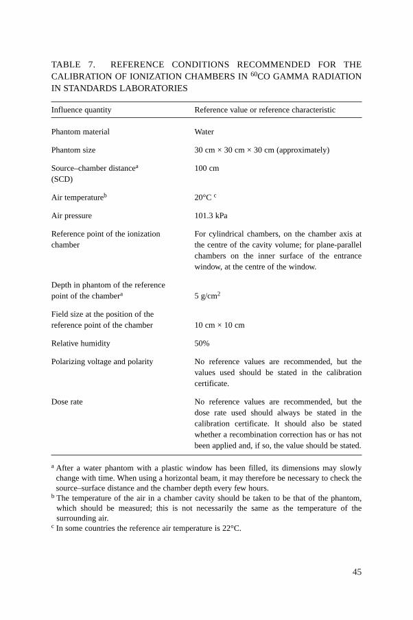
45
TABLE 7. REFERENCE CONDITIONS RECOMMENDED FOR THECALIBRATION OF IONIZATION CHAMBERS IN 60CO GAMMA RADIATIONIN STANDARDS LABORATORIES
Influence quantity Reference value or reference characteristic
Phantom material Water
Phantom size 30 cm × 30 cm × 30 cm (approximately)
Source–chamber distancea 100 cm(SCD)
Air temperatureb 20°C c
Air pressure 101.3 kPa
Reference point of the ionization For cylindrical chambers, on the chamber axis at chamber the centre of the cavity volume; for plane-parallel
chambers on the inner surface of the entrance window, at the centre of the window.
Depth in phantom of the referencepoint of the chambera 5 g/cm2
Field size at the position of the reference point of the chamber 10 cm × 10 cm
Relative humidity 50%
Polarizing voltage and polarity No reference values are recommended, but thevalues used should be stated in the calibrationcertificate.
Dose rate No reference values are recommended, but the dose rate used should always be stated in the calibration certificate. It should also be statedwhether a recombination correction has or has notbeen applied and, if so, the value should be stated.
a After a water phantom with a plastic window has been filled, its dimensions may slowlychange with time. When using a horizontal beam, it may therefore be necessary to check thesource–surface distance and the chamber depth every few hours.
b The temperature of the air in a chamber cavity should be taken to be that of the phantom,which should be measured; this is not necessarily the same as the temperature of thesurrounding air.
c In some countries the reference air temperature is 22°C.
46
conditions recommended for the calibration of ionization chambers in 60Co are givenin Table 7.
4.3.2. Calibration in kilovoltage X rays
As noted in Section 4.1, a chamber used to measure medium or low energyX rays must be calibrated in beams of similar quality to the beams that will bemeasured. At the time of writing this Code of Practice, only one PSDL has primarystandards of absorbed dose to water for kilovoltage X ray qualities [45]. However,it is possible to derive calibration factors in terms of absorbed dose to water fromair kerma calibration factors using one of the accepted protocols or Codes ofPractice for the dosimetry of X ray beams (see Appendix I.2). Thus any calibrationlaboratory with standards of air kerma can in this way provide derived calibrationfactors in terms of absorbed dose to water. Even though this is formally equivalentto the user obtaining an air kerma calibration factor and applying the same air kermaCode of Practice, it has the advantage of permitting the widespread use of the uni-fied methodology presented here in a field of dosimetry where standard methods arenotably lacking.
There is the possibility that there will be some inconsistency from one calibra-tion laboratory to another, depending on which code of practice is used to derive thecalibration factors in terms of absorbed dose to water. But this clearly will not add tothe inconsistency that already exists in clinical kilovoltage dosimetry because of theuse of the differing dosimetry protocols and codes of practice. Any laboratoryoffering derived calibrations must document fully how the derivation was obtained, inorder that differences may be resolved, if necessary, and to maintain traceability to theoriginal air kerma primary standards.
Because of the variety of auxiliary dosimetry equipment such as phantoms,waterproofing sleeves and buildup foils, and the variety of field sizes and SSDs thatwill be clinically relevant, it is important that the clinical measurement conditions arereproduced as closely as possible in the calibration process. When a chamber is sentfor calibration, all relevant auxiliary equipment should be supplied as well, and thedetails of the clinical beams in which it will be used clearly specified.
Typical reference conditions for the calibration of ionization chambers inkilovoltage X ray beams are given in Table 8.
4.3.3. Calibration at other qualities
Only standards laboratories with an accelerator can perform calibrations in highenergy photon and electron beams. The user will be given either a series of calibra-tion factors ND,w,Q at various beam qualities or a calibration factor ND,w,Qo
, plus
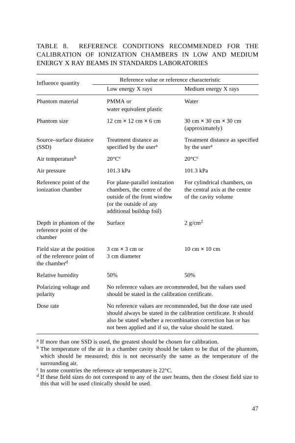
47
TABLE 8. REFERENCE CONDITIONS RECOMMENDED FOR THECALIBRATION OF IONIZATION CHAMBERS IN LOW AND MEDIUMENERGY X RAY BEAMS IN STANDARDS LABORATORIES
Influence quantity Reference value or reference characteristic
Low energy X rays Medium energy X rays
Phantom material PMMA or Waterwater equivalent plastic
Phantom size 12 cm × 12 cm × 6 cm 30 cm × 30 cm × 30 cm (approximately)
Source–surface distance Treatment distance as Treatment distance as specified(SSD) specified by the usera by the usera
Air temperatureb 20°Cc 20°Cc
Air pressure 101.3 kPa 101.3 kPa
Reference point of the For plane-parallel ionization For cylindrical chambers, on ionization chamber chambers, the centre of the the central axis at the centre
outside of the front window of the cavity volume(or the outside of any additional buildup foil)
Depth in phantom of the Surface 2 g/cm2
reference point of the chamber
Field size at the position 3 cm × 3 cm or 10 cm × 10 cmof the reference point of 3 cm diameterthe chamberd
Relative humidity 50% 50%
Polarizing voltage and No reference values are recommended, but the values usedpolarity should be stated in the calibration certificate.
Dose rate No reference values are recommended, but the dose rate usedshould always be stated in the calibration certificate. It shouldalso be stated whether a recombination correction has or has not been applied and if so, the value should be stated.
a If more than one SSD is used, the greatest should be chosen for calibration.b The temperature of the air in a chamber cavity should be taken to be that of the phantom,
which should be measured; this is not necessarily the same as the temperature of thesurrounding air.
c In some countries the reference air temperature is 22°C.d If these field sizes do not correspond to any of the user beams, then the closest field size to
this that will be used clinically should be used.
48
measured values for kQ,Qo. Details on the calibration procedures at PSDLs are outside
the scope of this report.It should be noted that no standards of absorbed dose to water are yet available
for proton and heavy ion beams. However, a calibration factor in terms of absorbeddose to water can be obtained in the user beam when the standards laboratory is pre-pared to perform calibration measurements (with water calorimetry for instance) inthe therapy centre.
4.4. REFERENCE DOSIMETRY IN THE USER BEAM
4.4.1. Determination of the absorbed dose to water
It is assumed that the user has an ionization chamber or a dosimeter with acalibration factor ND,w,Qo
in terms of absorbed dose to water at a reference quality Qo.Following the formalism given in Section 3, the chamber is positioned according tothe reference conditions and the absorbed dose to water is given by
Dw,Q = MQND,w,QokQo
(10)
where MQ is the reading of the dosimeter incorporating the product ∏ki of correctionfactors for influence quantities, and kQ,Qo
is the correction factor which corrects forthe difference between the reference beam quality Qo and the actual quality Q beingused. This equation is valid for all the radiation fields for which this Code of Practiceapplies.
Details on the reference conditions to be used for radiotherapy beam calibra-tions and values for the factor kQ,Qo
will be given in the individual sections dealingwith the various radiation types. Recommendations on relative dosimetry, namely thedetermination of distributions of absorbed dose, will also be given in the respectivesections. Although the correction factor kQ,Qo
is not different in kind from all othercorrection factors for influence quantities, because of its dominant role it is treatedseparately in each section.
4.4.2. Practical considerations for measurements in the user beam
Precautions with regard to the waterproof sleeve of a chamber when carrying outmeasurements in a water phantom have been given in Section 4.2.4. Beforemeasurements are made, the stability of the dosimeter system should be verified usinga check source. Enough time should be allowed for the dosimeter to reach thermal equi-librium. Some mains powered electrometers are best switched on for at least 2 h before
49
use to allow stabilization. It is always advisable to pre-irradiate an ionization chamberwith 2–5 Gy to achieve charge equilibrium in the different materials. It is especiallyimportant to operate the measuring system under stable conditions whenever thepolarity or polarizing voltage are modified which, depending on the chamber andsometimes on the polarity, might require several (up to 20) minutes. Indeed, failure todo so may result in errors which are larger than the effect for which one is correcting.
The leakage current is that generated by the complete measuring system in theabsence of radiation. Leakage can also be radiation induced and chambers may showno leakage prior to irradiation yet have a significant leakage after irradiation. Theleakage current should always be measured before and after irradiation, and shouldbe small compared with the current obtained during the irradiation (less than approx-imately 0.1% of the measurement current and normally of the same sign). In someinstances, for example small volume chambers used at low dose rates, the relativeleakage current may be larger. If this is the case, the measurement current should becorrected for leakage, paying attention to the sign of the leakage current. Chamberswith a leakage current which is large (approximately larger than 1% of the measure-ment current) or variable in time should not be used.
When relative measurements are carried out in accelerator and in kilovoltageX ray beams it is strongly recommended that an additional monitoring dosimetrysystem be used during the experimental procedure to account for fluctuations in theradiation output. This is especially important when ratios of dosimeter readings areused (cross-calibrations, measurements with different polarities or varying voltages,etc.). The external monitor should preferably be positioned within the phantom, alongthe major axis of the transverse plane, at the same depth as the chamber and at adistance of approximately 3 or 4 cm from the central axis; if the monitor is positionedin air the possible temperature drifts should be taken into account.
4.4.3. Correction for influence quantities
The calibration factor for an ionization chamber is valid only for the refer-ence conditions which apply to the calibration. Any departure from the referenceconditions when using the ionization chamber in the user beam should be correctedfor using appropriate factors. In the following only general correction factors, ki,are discussed, leaving items specific to each type of radiation beam to the relevantsection.
4.4.3.1. Pressure, temperature and humidity
As all chambers recommended in this report are open to the ambient air, themass of air in the cavity volume is subject to atmospheric variations. The correctionfactor
50
(11)
should be applied to convert the cavity air mass to the reference conditions. P and Tare the cavity air pressure and temperature at the time of the measurements, and Poand To are the reference values (generally 101.3 kPa and 20°C).15 The temperature ofthe air in a chamber cavity should be taken to be that of the phantom, which shouldbe measured; this is not necessarily the same as the temperature of the surroundingair.16 For measurements in a water phantom, the chamber waterproof sleeve shouldbe vented to the atmosphere in order to obtain rapid equilibrium between the ambientair and the air in the chamber cavity.
No corrections for humidity are needed if the calibration factor was referred toa relative humidity of 50% and is used in a relative humidity between 20 and 80%. Ifthe calibration factor is referred to dry air, a correction factor should be applied [68];for 60Co calibrations kh = 0.997.
4.4.3.2. Electrometer calibration
When the ionization chamber and the electrometer are calibrated separately, acalibration factor for each is given by the calibration laboratory. In this Code ofPractice, the electrometer calibration factor kelec is treated as an influence quantityand is included in the product ∏ki of correction factors. Typically, the calibrationfactor ND,w for the ionization chamber will be given in units of Gy/nC and that forthe electrometer kelec either in units of nC/rdg or, if the electrometer readout is interms of charge, as a dimensionless factor close to unity (effectively a calibration inunits of nC/nC).
If the ionization chamber and the electrometer are calibrated together, then thecombined calibration factor ND,w will typically be given in units of Gy/rdg or Gy/nC(depending on the electrometer readout) and no separate electrometer calibrationfactor kelec is required. In this case, a value for kelec of unity (dimensionless) shouldbe recorded in the worksheets.
4.4.3.3. Polarity effect
The effect on a chamber reading of using polarizing potentials of oppositepolarity must always be checked on commissioning. For most chamber types the
(273.2 )
(273.2 )o
TPo
PTk
T P
+=
+
15 In some countries the reference temperature is 22°C.16 The equilibrium temperature of a water phantom that has been filled for some hours
will usually be a degree or so lower than room temperature because of evaporation from thewater surface.
51
effect will be negligible in photon beams, a notable exception being the very thinwindow chambers used for low energy X rays. In charged particle beams, particularlyelectrons,17 the effect may be significant.
When a chamber is used in a beam that produces a measurable polarity effect,the true reading is taken to be the mean of the absolute values of readings taken atboth polarities. For the routine use of a given ionization chamber, a single polarizingpotential and polarity is normally adopted. However, the effect on the chamberreading of using polarizing potentials of opposite polarity for each user beam qualityQ can be accounted for by using a correction factor
(12)
where M+ and M– are the electrometer readings obtained at positive and negativepolarity, respectively, and M is the electrometer reading obtained with the polarityused routinely (positive or negative). The readings M+ and M– should be made withcare, ensuring that the chamber reading is stable following any change in polarity(some chambers can take up to 20 min to stabilize). To minimize the influence of fluc-tuations in the output of radiation generators (clinical accelerators, X ray therapyunits, etc.), it is preferable that all the readings be normalized to that of an externalmonitor. Ideally, the external monitor should be positioned approximately at the depthof measurement, but at a distance of 3–4 cm from the chamber centre along the majoraxis in the transverse plane of the beam.
When the chamber is sent for calibration, a decision is normally made, eitherby the user or by the calibration laboratory, on the polarizing potential and polarity tobe adopted for the routine use of the chamber. The calibration should be carried outat this polarizing potential (and polarity, if only one polarity is used for the calibra-tion), or, if not, clearly stated. The calibration laboratory may or may not correct forthe polarity effect at the calibration quality Qo. This should be stated in the calibra-tion certificate.
When the calibration laboratory has already corrected for the polarity effect,then the user must apply the correction factor kpol derived using Eq. (12) to all mea-surements made using the routine polarity. When the calibration laboratory has not
pol 2+ –M M
kM
+=
17 For plane-parallel chambers the polarity effect is generally more pronounced in lowenergy electron beams [21]. However, for certain chamber types it has been shown that thepolarity effect increases with energy [69]. For this reason the polarity effect should always beinvestigated at all electron energies.
52
corrected for the polarity effect, the subsequent treatment of the polarity effectdepends on the facilities available to the user, and on what beam qualities must bemeasured:(a) If the user beam quality is the same as the calibration quality and the chamber
is used at the same polarizing potential and polarity, then kpol will be the samein both cases and the user must not apply a polarity correction for that partic-ular beam (or equivalently kpol is set equal to 1 in the worksheet). If it is notpossible to use the same polarizing potential then the polarity effect will notbe exactly the same in both cases. The difference should be small and shouldbe estimated and included as an uncertainty.
(b) If the user beam quality is not the same as the calibration quality, but it ispossible to reproduce the calibration quality, then the polarity correction [kpol]Qo
that was not applied at the time of calibration must be estimated using Eq. (12)and using the same polarizing potential and polarity as was used at thecalibration laboratory. The polarity effect at the user beam quality, kpol, mustalso be determined from Eq. (12) using the polarizing potential and polarityadopted for routine use. A modified polarity correction is then evaluated asfollows:
(13)
This is then used to correct the dosimeter readings for polarity for each beamquality Q.Note that if the user beam quality is not the same as the calibration quality and
it is not possible to reproduce the calibration quality to estimate the correction[kpol]Qo
, then this must be estimated from a knowledge of the chamber response todifferent beam qualities and polarities. If this can not be done with a relative standarduncertainty (see Appendix IV.3) of less than 0.5%, then either the chamber should notbe used or it should be sent to a calibration laboratory that can perform the requiredpolarity correction.
4.4.3.4. Ion recombination
The incomplete collection of charge in an ionization chamber cavity owing tothe recombination of ions requires the use of a correction factor ks. Two separateeffects take place: (i) the recombination of ions formed by separate ionizing particletracks, termed general (or volume) recombination, which is dependent on the densityof ionizing particles and therefore on the dose rate; and (ii) the recombination of ionsformed by a single ionizing particle track, referred to as initial recombination, which
polpol
pol[ ]Qo
kk =
k
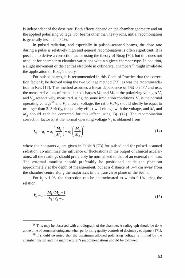
53
is independent of the dose rate. Both effects depend on the chamber geometry and onthe applied polarizing voltage. For beams other than heavy ions, initial recombinationis generally less than 0.2%.
In pulsed radiation, and especially in pulsed–scanned beams, the dose rateduring a pulse is relatively high and general recombination is often significant. It ispossible to derive a correction factor using the theory of Boag [70], but this does notaccount for chamber to chamber variations within a given chamber type. In addition,a slight movement of the central electrode in cylindrical chambers18 might invalidatethe application of Boag’s theory.
For pulsed beams, it is recommended in this Code of Practice that the correc-tion factor ks be derived using the two voltage method [72], as was the recommenda-tion in Ref. [17]. This method assumes a linear dependence of 1/M on 1/V and usesthe measured values of the collected charges M1 and M2 at the polarizing voltages V1and V2, respectively, measured using the same irradiation conditions. V1 is the normaloperating voltage19 and V2 a lower voltage; the ratio V1/V2 should ideally be equal toor larger than 3. Strictly, the polarity effect will change with the voltage, and M1 andM2 should each be corrected for this effect using Eq. (12). The recombinationcorrection factor ks at the normal operating voltage V1 is obtained from
(14)
where the constants ai are given in Table 9 [73] for pulsed and for pulsed–scannedradiation. To minimize the influence of fluctuations in the output of clinical acceler-ators, all the readings should preferably be normalized to that of an external monitor.The external monitor should preferably be positioned inside the phantomapproximately at the depth of measurement, but at a distance of 3–4 cm away fromthe chamber centre along the major axis in the transverse plane of the beam.
For ks < 1.03, the correction can be approximated to within 0.1% using therelation
(15)1 2
1 2
11
1sM M
kV V
-- =
-
21 1
1 22 2
s oM M
k a a aM M
Ê ˆ Ê ˆ= + +Á ˜ Á ˜Ë ¯ Ë ¯
18 This may be observed with a radiograph of the chamber. A radiograph should be doneat the time of commissioning and when performing quality controls of dosimetry equipment [71].
19 It should be noted that the maximum allowed polarizing voltage is limited by thechamber design and the manufacturer’s recommendations should be followed.
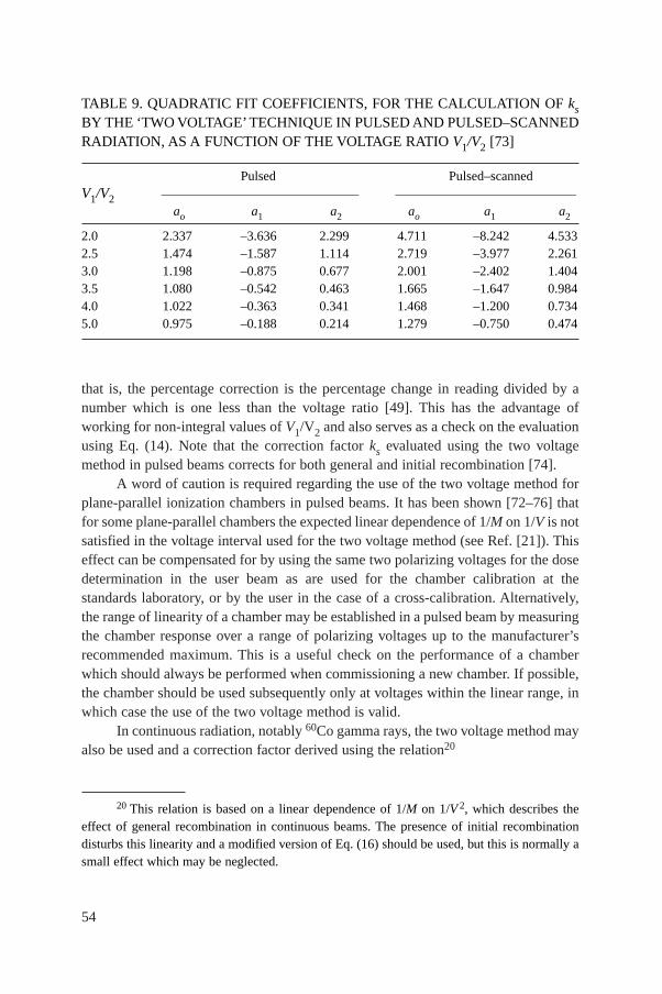
54
that is, the percentage correction is the percentage change in reading divided by anumber which is one less than the voltage ratio [49]. This has the advantage ofworking for non-integral values of V1/V2 and also serves as a check on the evaluationusing Eq. (14). Note that the correction factor ks evaluated using the two voltagemethod in pulsed beams corrects for both general and initial recombination [74].
A word of caution is required regarding the use of the two voltage method forplane-parallel ionization chambers in pulsed beams. It has been shown [72–76] thatfor some plane-parallel chambers the expected linear dependence of 1/M on 1/V is notsatisfied in the voltage interval used for the two voltage method (see Ref. [21]). Thiseffect can be compensated for by using the same two polarizing voltages for the dosedetermination in the user beam as are used for the chamber calibration at thestandards laboratory, or by the user in the case of a cross-calibration. Alternatively,the range of linearity of a chamber may be established in a pulsed beam by measuringthe chamber response over a range of polarizing voltages up to the manufacturer’srecommended maximum. This is a useful check on the performance of a chamberwhich should always be performed when commissioning a new chamber. If possible,the chamber should be used subsequently only at voltages within the linear range, inwhich case the use of the two voltage method is valid.
In continuous radiation, notably 60Co gamma rays, the two voltage method mayalso be used and a correction factor derived using the relation20
20 This relation is based on a linear dependence of 1/M on 1/V 2, which describes theeffect of general recombination in continuous beams. The presence of initial recombinationdisturbs this linearity and a modified version of Eq. (16) should be used, but this is normally asmall effect which may be neglected.
TABLE 9. QUADRATIC FIT COEFFICIENTS, FOR THE CALCULATION OF ksBY THE ‘TWO VOLTAGE’ TECHNIQUE IN PULSED AND PULSED–SCANNEDRADIATION, AS A FUNCTION OF THE VOLTAGE RATIO V1/V2 [73]
Pulsed Pulsed–scannedV1/V2
____________________________________ _________________________________
ao a1 a2 ao a1 a2
2.0 2.337 –3.636 2.299 4.711 –8.242 4.5332.5 1.474 –1.587 1.114 2.719 –3.977 2.2613.0 1.198 –0.875 0.677 2.001 –2.402 1.4043.5 1.080 –0.542 0.463 1.665 –1.647 0.9844.0 1.022 –0.363 0.341 1.468 –1.200 0.7345.0 0.975 –0.188 0.214 1.279 –0.750 0.474
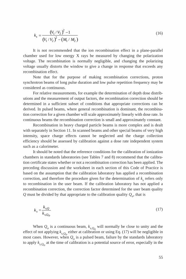
55
(16)
It is not recommended that the ion recombination effect in a plane-parallelchamber used for low energy X rays be measured by changing the polarizationvoltage. The recombination is normally negligible, and changing the polarizingvoltage usually distorts the window to give a change in response that exceeds anyrecombination effect.
Note that for the purpose of making recombination corrections, protonsynchrotron beams of long pulse duration and low pulse repetition frequency may beconsidered as continuous.
For relative measurements, for example the determination of depth dose distrib-utions and the measurement of output factors, the recombination correction should bedetermined in a sufficient subset of conditions that appropriate corrections can bederived. In pulsed beams, where general recombination is dominant, the recombina-tion correction for a given chamber will scale approximately linearly with dose rate. Incontinuous beams the recombination correction is small and approximately constant.
Recombination in heavy charged particle beams is more complex and is dealtwith separately in Section 11. In scanned beams and other special beams of very highintensity, space charge effects cannot be neglected and the charge collectionefficiency should be assessed by calibration against a dose rate independent systemsuch as a calorimeter.
It should be noted that the reference conditions for the calibration of ionizationchambers in standards laboratories (see Tables 7 and 8) recommend that the calibra-tion certificate states whether or not a recombination correction has been applied. Thepreceding discussion and the worksheet in each section of this Code of Practice isbased on the assumption that the calibration laboratory has applied a recombinationcorrection, and therefore the procedure given for the determination of ks refers onlyto recombination in the user beam. If the calibration laboratory has not applied arecombination correction, the correction factor determined for the user beam qualityQ must be divided by that appropriate to the calibration quality Qo, that is
(17)
When Qo is a continuous beam, ks,Qowill normally be close to unity and the
effect of not applying ks,Qoeither at calibration or using Eq. (17) will be negligible in
most cases. However, when Qo is a pulsed beam, failure by the standards laboratoryto apply ks,Qo
at the time of calibration is a potential source of error, especially in the
s,Qs
s,Qo
kk =
k
( )( ) ( )
21 2
21 2 1 2
/ 1
/ /s
V Vk
V V M M
-=
-
56
case where the dose per pulse in the user beam is very different from that used at cal-ibration. If this is the case the user must determine ks,Qo
in the clinic at a dose perpulse similar to that used at calibration (this may not be the dose per pulse normallyused in the clinic). This determination does not need to be carried out at Qo; it is thematching of the calibration dose per pulse which is important. To avoid a recurrenceof this problem, the user should request that a recombination correction be applied,or at least measured, at the next calibration at a standards laboratory, especially forcalibration in pulsed beams.
57
5. CODE OF PRACTICE FOR 60Co GAMMA RAY BEAMS
5.1. GENERAL
This section provides a Code of Practice for reference dosimetry (beamcalibration) in the user’s 60Co gamma ray beam and recommendations for relativedosimetry. It is based upon a calibration factor in terms of absorbed dose to waterND,w,Qo
for a dosimeter in a reference beam of quality Qo, where Qo is 60Co. In thissituation Dw,Q is denoted by Dw, kQ,Qo
is denoted by kQ which has a value of unity,and ND,w,Qo
is denoted by ND,w.
5.2. DOSIMETRY EQUIPMENT
5.2.1. Ionization chambers
The recommendations regarding ionization chambers given in Section 4.2.1should be followed. Both cylindrical and plane-parallel21 ionization chambers arerecommended as reference instruments for the calibration of 60Co gamma ray beams.The reference point of a cylindrical chamber for the purpose of calibration at thestandards laboratory and for measurements under reference conditions in the userbeam is taken to be on the chamber axis at the centre of the cavity volume. For plane-parallel chambers, it is taken to be on the inner surface of the entrance window, at thecentre of the window. This point should be positioned at the reference depth in a waterphantom. If a field instrument is used, this should be cross-calibrated against thecalibrated reference chamber (see Section 5.5).
5.2.2. Phantoms and chamber sleeves
The recommendations regarding phantoms and chamber sleeves given inSections 4.2.3 and 4.2.4 should be followed. Water is recommended as the referencemedium for measurements of absorbed dose with 60Co beams.22 The phantom shouldextend to at least 5 cm beyond all four sides of the field size employed at the depth
21 Plane-parallel chambers can be used for measurements under reference conditions inthe user’s 60Co gamma ray beam when they are calibrated at the same quality.
22 Plastic phantoms should not be used for reference dosimetry. However, they can beused for routine quality assurance measurements, provided a transfer factor between plastic andwater has been established.
58
of measurement and also extend to at least 5 g/cm2 beyond the maximum depth ofmeasurement.
In horizontal beams, the window of the phantom should be made of plastic andof thickness twin between 0.2 and 0.5 cm. The water equivalent thickness (in g/cm2)of the phantom window should be taken into account when evaluating the depth atwhich the chamber is to be positioned; the thickness is calculated as the producttwin (ρpl, where ρpl is the mass density of the plastic (in g/cm3). For the commonlyused plastics PMMA and clear polystyrene, the nominal values ρPMMA = 1.19 g/cm3
and ρpolystyrene = 1.06 g/cm3 [64] may be used for the calculation of the water equiv-alent thickness of the window.
For non-waterproof chambers, a waterproofing sleeve should be used, made ofPMMA and preferably not thicker than 1.0 mm. The air gap between the chamberwall and the waterproofing sleeve should be sufficient (0.1–0.3 mm) to allow the airpressure in the chamber to equilibrate. The same waterproofing sleeve that was usedfor calibration of the user’s ionization chamber should also be used for referencedosimetry. If it is not possible to use the same waterproofing sleeve that was usedduring calibration at the standardizing laboratory, then another sleeve of the samematerial and of similar thickness should be used. Plane-parallel chambers, if notinherently waterproof or supplied with a waterproof cover, must be used in a water-proof enclosure, preferably of PMMA or a material that closely matches the chamberwalls; ideally, there should be no more than 1 mm of added material in front of andbehind the cavity volume.
5.3. BEAM QUALITY SPECIFICATION
Gamma ray spectra from 60Co therapy sources used at hospitals or SSDLs havea substantial component of low energy scattered photons, originated in the sourceitself or in the treatment head, but ionization chamber measurements are not expectedto be influenced by 60Co spectral differences by more than a few tenths of one percent [29]. For this reason,60Co gamma rays for radiotherapy dosimetry do not requirea beam quality specifier other than the radionuclide.
5.4. DETERMINATION OF ABSORBED DOSE TO WATER
5.4.1. Reference conditions
The reference conditions for the determination of absorbed dose to water in a60Co gamma ray beam are given in Table 10.
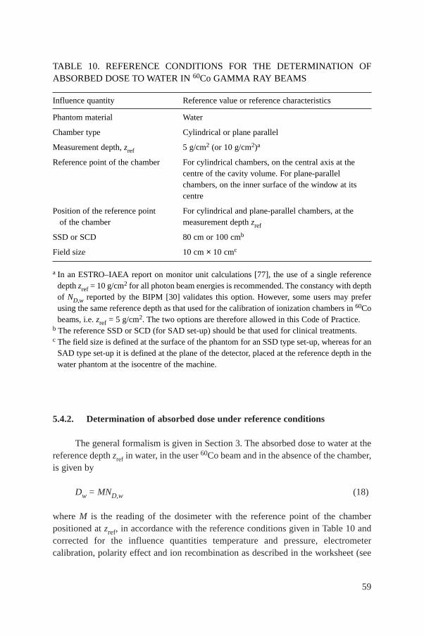
59
5.4.2. Determination of absorbed dose under reference conditions
The general formalism is given in Section 3. The absorbed dose to water at thereference depth zref in water, in the user 60Co beam and in the absence of the chamber,is given by
Dw = MND,w (18)
where M is the reading of the dosimeter with the reference point of the chamberpositioned at zref, in accordance with the reference conditions given in Table 10 andcorrected for the influence quantities temperature and pressure, electrometercalibration, polarity effect and ion recombination as described in the worksheet (see
TABLE 10. REFERENCE CONDITIONS FOR THE DETERMINATION OFABSORBED DOSE TO WATER IN 60Co GAMMA RAY BEAMS
Influence quantity Reference value or reference characteristics
Phantom material Water
Chamber type Cylindrical or plane parallel
Measurement depth, zref 5 g/cm2 (or 10 g/cm2)a
Reference point of the chamber For cylindrical chambers, on the central axis at the centre of the cavity volume. For plane-parallelchambers, on the inner surface of the window at itscentre
Position of the reference point For cylindrical and plane-parallel chambers, at the of the chamber measurement depth zref
SSD or SCD 80 cm or 100 cmb
Field size 10 cm × 10 cmc
a In an ESTRO–IAEA report on monitor unit calculations [77], the use of a single referencedepth zref = 10 g/cm2 for all photon beam energies is recommended. The constancy with depthof ND,w reported by the BIPM [30] validates this option. However, some users may preferusing the same reference depth as that used for the calibration of ionization chambers in 60Cobeams, i.e. zref = 5 g/cm2. The two options are therefore allowed in this Code of Practice.
b The reference SSD or SCD (for SAD set-up) should be that used for clinical treatments.c The field size is defined at the surface of the phantom for an SSD type set-up, whereas for an
SAD type set-up it is defined at the plane of the detector, placed at the reference depth in thewater phantom at the isocentre of the machine.
60
also Section 4.4.3). For 60Co units, the timer error can influence M significantly. Amethod for calculating the timer error is given in the worksheet. ND,w is the calibra-tion factor in terms of absorbed dose to water for the dosimeter at the referencequality 60Co.
5.4.3. Absorbed dose at zmax
Section 5.4.2 provides a methodology for determining absorbed dose at zref.However, clinical dosimetry calculations are often referred to the depth of dose max-imum, zmax. To determine the absorbed dose at zmax the user should, for a given beam,use the central axis percentage depth dose (PDD) data for SSD set-ups and tissuemaximum ratios (TMR) for SAD set-ups.
5.5. CROSS-CALIBRATION OF FIELD IONIZATION CHAMBERS
As noted in Section 5.2.1, a field chamber (either cylindrical or plane-parallel)may be cross-calibrated against a calibrated reference chamber in a 60Co beam at theuser facility. The chambers are compared by alternately placing each chamber in awater phantom with its reference point at zref in accordance with the reference condi-tions given in Table 10. A side by side chamber intercomparison is a possible alter-native configuration. The calibration factor in terms of absorbed dose to water for thefield ionization chamber is given by
(19)
where Mref and Mfield are the meter readings per unit time for the reference and fieldchambers, respectively, corrected for the influence quantities as described inSection 4.4.3 and is the calibration factor in terms of absorbed dose to waterfor the reference chamber. The field chamber with the calibration factor
may be used subsequently for the determination of absorbed dose to water in the user 60Co beam using the procedure of Section 5.4.2, where ND,w is replacedby .
5.6. MEASUREMENTS UNDER NON-REFERENCE CONDITIONS
Clinical dosimetry requires the measurements of central axis percentagedepth dose (PDD) distributions, tissue phantom ratios (TPR) or tissue maximumratios (TMR), isodose distributions, transverse beam profiles and output factors as
fieldD,wN
fieldD,wN
refD,wN
field refref
fieldD,w D,w
MN = N
M
61
a function of field size and shape for both reference and non-reference conditions.Such measurements should be made for all possible combinations of field size andSSD or SAD used for radiotherapy treatment.
5.6.1. Central axis depth dose distributions
All measurements should follow the recommendations given in Section 4.2regarding choices for phantoms and dosimeters, although other types of detectorscan also be used. For measurements of depth ionization curves, plane-parallel ion-ization chambers are recommended. If a cylindrical ionization chamber is usedinstead, then the effective point of measurement of the chamber must be taken intoaccount. This requires that the complete depth ionization distribution be shiftedtowards the surface a distance equal to 0.6 rcyl [17, 21], where rcyl is the cavity radiusof the cylindrical ionization chamber. To make accurate measurements in the buildupregion, extrapolation chambers or well guarded fixed separation plane-parallelchambers should be used. Care should be taken in the use of certain solid state detec-tors (some types of diodes and diamond detectors) to measure depth dose distribu-tions (see, for instance, Ref. [21]); only a solid state detector whose response hasbeen regularly verified against a reference detector (ion chamber) should be selectedfor these measurements.
Since the stopping-power ratios and perturbation effects can be assumed to areasonable accuracy to be independent of depth and field size [78], relative ionizationdistributions can be used as relative distributions of absorbed dose, at least for depthsat and beyond the depth of dose maximum.
5.6.2. Output factors
The output factor may be determined as the ratio of corrected dosimeter read-ings measured under a given set of non-reference conditions to that measured underreference conditions. These measurements are typically done at the depth of max-imum dose or at the reference depth [77] and corrected to the depth of maximum doseusing percentage depth dose data (or TMR). When output factors are measured inopen as well as wedged beams, special attention should be given to the uniformity ofthe radiation fluence over the chamber cavity. This is especially important for fieldsizes less than 5 cm × 5 cm.
In wedged beams the radiation intensity varies strongly in the direction of thewedge. For output measurements in such beams the detector dimension in the wedgedirection should be as small as possible. Small thimble chambers aligned with theiraxis perpendicular to the wedge direction are recommended. The coincidence of thecentral axes of the beam, the collimator and the wedge should be ensured prior tomaking the output measurements.
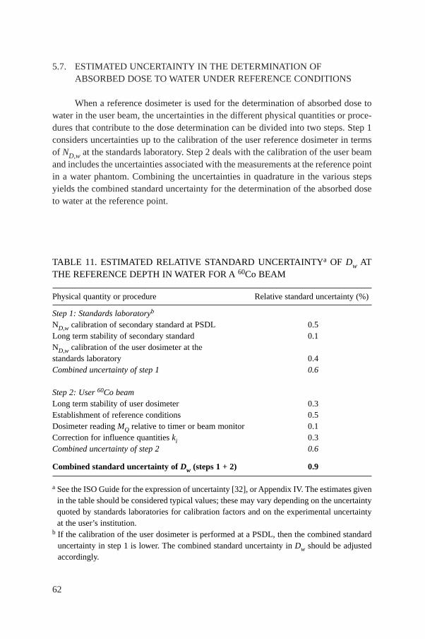
62
5.7. ESTIMATED UNCERTAINTY IN THE DETERMINATION OFABSORBED DOSE TO WATER UNDER REFERENCE CONDITIONS
When a reference dosimeter is used for the determination of absorbed dose towater in the user beam, the uncertainties in the different physical quantities or proce-dures that contribute to the dose determination can be divided into two steps. Step 1considers uncertainties up to the calibration of the user reference dosimeter in termsof ND,w at the standards laboratory. Step 2 deals with the calibration of the user beamand includes the uncertainties associated with the measurements at the reference pointin a water phantom. Combining the uncertainties in quadrature in the various stepsyields the combined standard uncertainty for the determination of the absorbed doseto water at the reference point.
TABLE 11. ESTIMATED RELATIVE STANDARD UNCERTAINTYa OF Dw ATTHE REFERENCE DEPTH IN WATER FOR A 60Co BEAM
Physical quantity or procedure Relative standard uncertainty (%)
Step 1: Standards laboratoryb
ND,w calibration of secondary standard at PSDL 0.5Long term stability of secondary standard 0.1ND,w calibration of the user dosimeter at the standards laboratory 0.4Combined uncertainty of step 1 0.6
Step 2: User 60Co beamLong term stability of user dosimeter 0.3Establishment of reference conditions 0.5Dosimeter reading MQ relative to timer or beam monitor 0.1Correction for influence quantities ki 0.3Combined uncertainty of step 2 0.6
Combined standard uncertainty of Dw (steps 1 + 2) 0.9
a See the ISO Guide for the expression of uncertainty [32], or Appendix IV. The estimates givenin the table should be considered typical values; these may vary depending on the uncertaintyquoted by standards laboratories for calibration factors and on the experimental uncertaintyat the user’s institution.
b If the calibration of the user dosimeter is performed at a PSDL, then the combined standarduncertainty in step 1 is lower. The combined standard uncertainty in Dw should be adjustedaccordingly.
63
An estimate of the uncertainties in the calibration of a 60Co beam is given inTable 11. When the calibration of the reference dosimeter is carried out in an SSDL,the combined standard uncertainty in Dw is estimated to be typically around 0.9%.This estimate may vary depending on the uncertainty quoted by the calibration labo-ratory. If a field dosimeter is used, the uncertainty in dose determination increasessomewhat (by approximately 0.2%) because of the additional step needed to cross-calibrate the field dosimeter against the calibrated reference dosimeter.
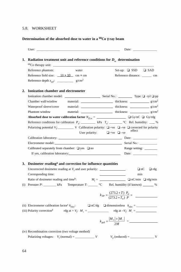
64
5.8. WORKSHEET
Determination of the absorbed dose to water in a 60Co γγ ray beam
User: ____________________________________________________ Date: _______________
1. Radiation treatment unit and reference conditions for Dw determination60Co therapy unit: _______________________________________________________________
Reference phantom: water Set-up: ❏ SSD ❏ SAD
Reference field size: cm × cm Reference distance: ______ cm
Reference depth zref: __________ g/cm2
2. Ionization chamber and electrometer
Ionization chamber model: Serial No.: Type: ❏ cyl ❏ pp
Chamber wall/window material: thickness: g/cm2
Waterproof sleeve/cover material: thickness: g/cm2
Phantom window material: thickness: g/cm2
Absorbed dose to water calibration factor ND,w = ❏ Gy/nC ❏ Gy/rdg
Reference conditions for calibration Po: _________ kPa To: ________ °C Rel. humidity: ____ %
Polarizing potential Vl:__________ V Calibration polarity: ❏ +ve ❏ –ve ❏ corrected for polarity
User polarity: ❏ +ve ❏ –veeffect
Calibration laboratory: Date: _______________
Electrometer model: Serial No.: ___________
Calibrated separately from chamber: ❏ yes ❏ no Range setting: ________
If yes, calibration laboratory: Date: _______________
3. Dosimeter readinga and correction for influence quantities
Uncorrected dosimeter reading at Vl and user polarity: ❏ nC ❏ rdg
Corresponding time: min
Ratio of dosimeter reading and timeb: Ml = ❏ nC/min ❏ rdg/min
(i) Pressure P: ________ kPa Temperature T: ______ °C Rel. humidity (if known): %
(ii) Electrometer calibration factorc kelec: ❏ nC/dg ❏ dimensionless kelec = _____________
(iii) Polarity correctiond rdg at + Vl: M+ = _____________ rdg at –Vl: M– =
=
(iv) Recombination correction (two voltage method)
Polarizing voltages: Vl (normal) = ____________ V V2 (reduced) = _______________ V
kM M
Mpol =++ -
2
kT
T
P
PTPo
o= ++
=( . )
( . )
273 2
273 2
10 × 10
65
Readingse at each V: M1 = ________________ M2 = __________________
Voltage ratio V1/V2 = ______________ Ratio of readings M1/M2 = ______________
Corrected dosimeter reading at the voltage V1:
M = M1/kTPkeleckpolks = ❏ nC/min ❏ rdg/min
4. Absorbed dose rate to water at the reference depth zref
Dw(zref) = M ND,w = Gy/min
5. Absorbed dose rate to water at the depth of dose maximum zmax
Depth of dose maximum: zmax = 0.5 g/cm2
(i) SSD set-up
Percentage depth dose at zref for a 10 cm × 10 cm field size: PDD (zref = g/cm2) = %
Absorbed dose rate calibration at zmax:
Dw(zmax) = 100 Dw(zref)/PDD(zref) = Gy/min
(ii) SAD set-up
TMR at zref for a 10 cm × 10 cm field size: TMR (zref = g/cm2) =
Absorbed dose rate calibration at zmax:
Dw(zmax) = Dw(zref)/TMR (zref) = ______________ Gy/min
a All readings should be checked for leakage and corrected if necessary.b The timer error should be taken into account. The correction at voltage V1 can be determined according to
MA is the integrated reading in a time tA MA = _______ tA = ______ minMB is the integrated reading in n short exposures
of time tB/n each (2 ≤ n ≤ 5) MB = _______ tB = ______ min n = _____
Timer error, min (the sign of τ must be taken into account)
❏ nC/min ❏ rdg/min
c If the electrometer is not calibrated separately set kelec = 1.d M in the denominator of kpol denotes reading at the user polarity. Preferably, each reading in the equation
should be the average of the ratios of M (or M+ or M−) to the reading of an external monitor, Mem.e Strictly, readings should be corrected for polarity effect (average with both polarities). Preferably, each
reading in the equation should be the average of the ratios of M1 or M2 to the reading of an externalmonitor, Mem.
f It is assumed that the calibration laboratory has performed a recombination correction. Otherwise thefactor k′s = ks/ks,Qo
should be used instead of ks. When Qo is 60Co, ks,Qo(at the calibration laboratory) will
normally be close to unity and the effect of not using this equation will be negligible in most cases.
A1
A
MM = =
t + t
––
t tB A A Bn A B
M MM M
= =t
kV V
V V M Ms = -
-=( / )
( / ) ( / )1 2
2
1 22
1 2
1
66
6. CODE OF PRACTICE FOR HIGH ENERGY PHOTON BEAMS
6.1. GENERAL
This section provides a Code of Practice for reference dosimetry (beam cali-bration) in clinical high energy photon beams, and recommendations for relativedosimetry. It is based upon a calibration factor in terms of absorbed dose to waterND,w,Qo
for a dosimeter in a reference beam of quality Qo. The Code of Practiceapplies to photon beams generated by electrons with energies in the range from 1 to50 MeV.
For photon beams, the most common reference beam quality Qo is 60Co gammarays. Some PSDLs can provide calibration factors ND,w,Q at other photon beamqualities Q, but 60Co is the only quality available in most standards laboratories. Forthis reason all data given in this section have 60Co gamma rays as the referencequality. Users with access to other calibration qualities can still use this Code ofPractice by renormalizing the various ND,w,Q to the ND,w,Qo
of 60Co. The ratios ofND,w,Q to that of 60Co provide an experimental determination of the kQ factors (seeSections 4.1 and 6.5.2). Note that when the reference quality Qo is 60Co, kQ,Qo
isdenoted by kQ and ND,w,Qo
is denoted by ND,w. If available, directly measured valuesof kQ,Qo
or kQ for an individual chamber are the preferred option; if they are not avail-able, the calculated values of kQ for the appropriate chamber type given in this Codeof Practice should be used.
6.2. DOSIMETRY EQUIPMENT
6.2.1. Ionization chambers
The recommendations regarding ionization chambers given in Section 4.2.1should be followed. Only cylindrical ionization chambers are recommended forreference dosimetry in high energy photon beams. The chamber types for which dataare given in this Code of Practice are listed in Table 14 of Section 6.5.1. Plane-parallelchambers can only be used for relative dosimetry.23 For high energy photon beams
23 Only when a plane-parallel chamber has been calibrated in the same beam quality asthe user beam can this chamber be used for measurements in reference conditions. When cal-culated kQ values are used, the lack of data for the wall correction factor pwall for plane-parallelchambers in high energy photon beams (cf. Ref. [21]) makes these chambers inappropriate.
67
the reference point of a cylindrical chamber for the purpose of calibration at thestandards laboratory and for measurements under reference conditions in the userbeam is taken to be on the chamber axis at the centre of the cavity volume. For plane-parallel chambers it is taken to be on the inner surface of the entrance window, at thecentre of the window. This point should be positioned at the reference depth in a waterphantom. If a field instrument is used, this should be cross-calibrated against acalibrated reference chamber at the reference quality Qo (see Section 6.6).
6.2.2. Phantoms and chamber sleeves
The recommendations regarding phantoms and chamber sleeves given inSections 4.2.3 and 4.2.4 should be followed. Water is recommended as the referencemedium for measurements of absorbed dose and beam quality in photon beams.24
The phantom should extend to at least 5 cm beyond all four sides of the field sizeemployed at the depth of measurement and also extend to at least 5 g/cm2 beyond themaximum depth of measurement.
In horizontal beams, the window of the phantom should be made of plastic andof thickness twin between 0.2 and 0.5 cm. The water equivalent thickness (in g/cm2)of the phantom window should be taken into account when evaluating the depth atwhich the chamber is to be positioned; the thickness is calculated as the producttwin ρpl, where ρpl is the mass density of the plastic (in g/cm3). For the commonly usedplastics PMMA and clear polystyrene, the nominal values ρPMMA = 1.19 g/cm3 andρpolystyrene = 1.06 g/cm3 [64] may be used for the calculation of the water equivalentthickness of the window.
For non-waterproof chambers, a waterproofing sleeve should be used, made ofPMMA, and preferably not thicker than 1.0 mm. The air gap between the chamberwall and the waterproofing sleeve should be sufficient (0.1–0.3 mm) to allow the airpressure in the chamber to equilibrate. The same waterproofing sleeve that was usedfor calibration of the user’s ionization chamber should also be used for referencedosimetry. If it is not possible to use the same waterproofing sleeve that was usedduring calibration at the standardizing laboratory, then another sleeve of the samematerial and of similar thickness should be used.
24 Plastic phantoms should not be used for reference dosimetry. However, they can beused for routine quality assurance measurements, provided a transfer factor between plastic andwater has been established.
68
6.3. BEAM QUALITY SPECIFICATION
6.3.1. Choice of beam quality index
For high energy photons produced by clinical accelerators the beam quality Qis specified by the tissue phantom ratio TPR20,10. This is the ratio of the absorbeddoses at depths of 20 and 10 cm in a water phantom, measured with a constant SCDof 100 cm and a field size of 10 cm × 10 cm at the plane of the chamber.25
The most important characteristic of the beam quality index TPR20,10 is its inde-pendence of the electron contamination in the incident beam. It is also a measure of theeffective attenuation coefficient describing the approximately exponential decrease of aphoton depth dose curve beyond the depth of maximum dose [82–84]. As TPR20,10 isobtained as a ratio of doses, it does not require the use of displacement correction fac-tors at two depths when cylindrical chambers are used. Furthermore, TPR20,10 is in mostclinical set-ups not affected by small systematic errors in positioning the chamber ateach depth, as the settings in the two positions will be affected in a similar manner.
Other beam quality specifiers, such as the percentage depth dose at 10 cm depthand the depth of the 80% depth dose, have been proposed in the literature. An overviewof photon beam quality specifiers is given in Appendix III (see also Ref. [85]), basedon a description provided by the ICRU [29]. It should be emphasized, however, thatthere is no beam quality index that satisfies all possible requirements of being a uniqueindex for the entire energy range of this Code of Practice and all possible accelerators
25 TPR20,10 can also be obtained from the simple relation [79]:TPR20,10 = 1.2661 PDD20,10 – 0.0595
where PDD20,10 is the ratio of the per cent depth doses at 20 and 10 cm depths for a field sizeof 10 cm × 10 cm defined at the phantom surface with an SSD of 100 cm. This empirical equa-tion was obtained from a sample of almost 700 accelerators and has confirmed an earlier fit[80] used in Ref. [17]. Alternatively, TPR20,10 can be estimated from a fit to the data for thepercentage depth dose at 10 cm depth, PDD(10), measured for a 10 cm × 10 cm field size at anSSD of 100 cm. For the data published in Ref. [81] one obtains:
TPR20,10 = –0.7898 + 0.0329 PDD(10) – 0.000166 PDD(10)2
Except at the highest energy of 50 MV (corresponding to a PDD(10) value of 91%), the max-imum deviation of the data about the fit is about 0.6% and occurs at PDD(10) = 75%. AtPDD(10) = 91%, the deviation of the data about the fit is about 1%. Because electron contam-ination at the depth of maximum absorbed dose might affect the per cent depth dose at 10 cmdepth, the fit should only be used as an estimation of the relation between TPR20,10 andPDD(10), but not for beam calibration. Note that above 10 MV, the PDD(10) in the fit does notcoincide with the PDD(10)x used in Ref. [51], which refers exclusively to ‘pure’ photon beams,that is without electron contamination.
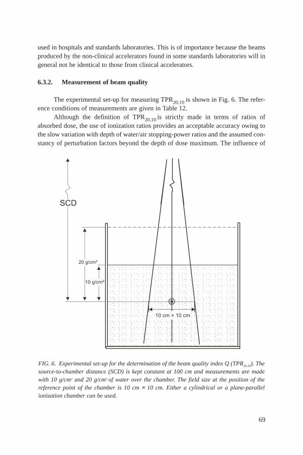
69
used in hospitals and standards laboratories. This is of importance because the beamsproduced by the non-clinical accelerators found in some standards laboratories will ingeneral not be identical to those from clinical accelerators.
6.3.2. Measurement of beam quality
The experimental set-up for measuring TPR20,10 is shown in Fig. 6. The refer-ence conditions of measurements are given in Table 12.
Although the definition of TPR20,10 is strictly made in terms of ratios ofabsorbed dose, the use of ionization ratios provides an acceptable accuracy owing tothe slow variation with depth of water/air stopping-power ratios and the assumed con-stancy of perturbation factors beyond the depth of dose maximum. The influence of
FIG. 6. Experimental set-up for the determination of the beam quality index Q (TPR20,10). Thesource-to-chamber distance (SCD) is kept constant at 100 cm and measurements are madewith 10 g/cm2 and 20 g/cm2 of water over the chamber. The field size at the position of thereference point of the chamber is 10 cm × 10 cm. Either a cylindrical or a plane-parallelionization chamber can be used.
10 g/cm²
20 g/cm²
10 cm × 10 cm
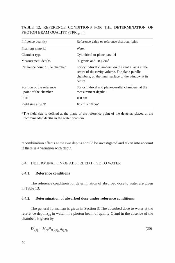
70
recombination effects at the two depths should be investigated and taken into accountif there is a variation with depth.
6.4. DETERMINATION OF ABSORBED DOSE TO WATER
6.4.1. Reference conditions
The reference conditions for determination of absorbed dose to water are givenin Table 13.
6.4.2. Determination of absorbed dose under reference conditions
The general formalism is given in Section 3. The absorbed dose to water at thereference depth zref in water, in a photon beam of quality Q and in the absence of thechamber, is given by
Dw,Q = MQ ND,w,QokQ,Qo
(20)
TABLE 12. REFERENCE CONDITIONS FOR THE DETERMINATION OFPHOTON BEAM QUALITY (TPR20,10)
Influence quantity Reference value or reference characteristics
Phantom material Water
Chamber type Cylindrical or plane parallel
Measurement depths 20 g/cm2 and 10 g/cm2
Reference point of the chamber For cylindrical chambers, on the central axis at the centre of the cavity volume. For plane-parallel chambers, on the inner surface of the window at its centre
Position of the reference For cylindrical and plane-parallel chambers, at the point of the chamber measurement depths
SCD 100 cm
Field size at SCD 10 cm × 10 cma
a The field size is defined at the plane of the reference point of the detector, placed at therecommended depths in the water phantom.
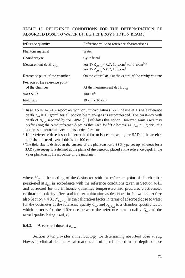
71
where MQ is the reading of the dosimeter with the reference point of the chamberpositioned at zref in accordance with the reference conditions given in Section 6.4.1and corrected for the influence quantities temperature and pressure, electrometercalibration, polarity effect and ion recombination as described in the worksheet (seealso Section 4.4.3). ND,w,Qo
is the calibration factor in terms of absorbed dose to waterfor the dosimeter at the reference quality Qo, and kQ,Qo
is a chamber specific factorwhich corrects for the difference between the reference beam quality Qo and theactual quality being used, Q.
6.4.3. Absorbed dose at zmax
Section 6.4.2 provides a methodology for determining absorbed dose at zref.However, clinical dosimetry calculations are often referenced to the depth of dose
TABLE 13. REFERENCE CONDITIONS FOR THE DETERMINATION OFABSORBED DOSE TO WATER IN HIGH ENERGY PHOTON BEAMS
Influence quantity Reference value or reference characteristics
Phantom material Water
Chamber type Cylindrical
Measurement depth zref For TPR20,10 < 0.7, 10 g/cm2 (or 5 g/cm2)a
For TPR20,10 ≥ 0.7, 10 g/cm2
Reference point of the chamber On the central axis at the centre of the cavity volume
Position of the reference point of the chamber At the measurement depth zref
SSD/SCD 100 cmb
Field size 10 cm × 10 cmc
a In an ESTRO–IAEA report on monitor unit calculations [77], the use of a single referencedepth zref = 10 g/cm2 for all photon beam energies is recommended. The constancy withdepth of ND,w reported by the BIPM [30] validates this option. However, some users mayprefer using the same reference depth as that used for 60Co beams, i.e. zref = 5 g/cm2; thisoption is therefore allowed in this Code of Practice.
b If the reference dose has to be determined for an isocentric set up, the SAD of the acceler-ator shall be used even if this is not 100 cm.
c The field size is defined at the surface of the phantom for a SSD type set-up, whereas for aSAD type set-up it is defined at the plane of the detector, placed at the reference depth in thewater phantom at the isocentre of the machine.
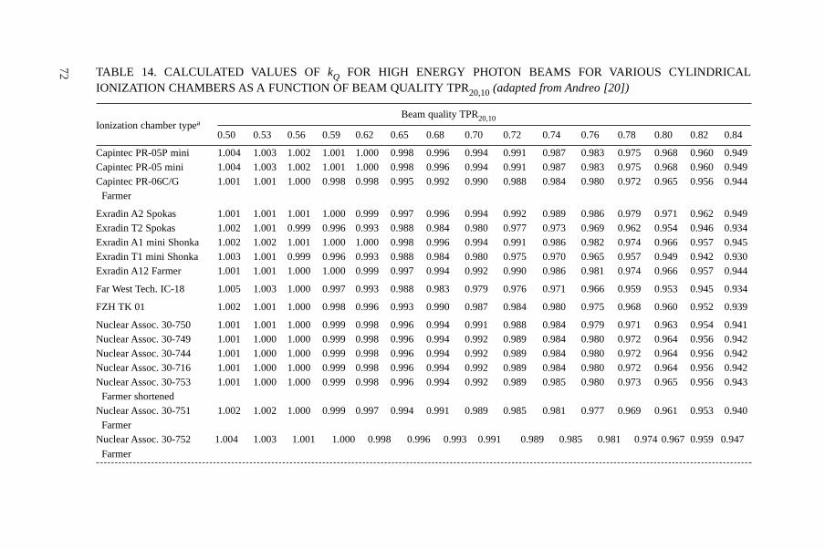
72 TABLE 14. CALCULATED VALUES OF kQ FOR HIGH ENERGY PHOTON BEAMS FOR VARIOUS CYLINDRICALIONIZATION CHAMBERS AS A FUNCTION OF BEAM QUALITY TPR20,10 (adapted from Andreo [20])
Beam quality TPR20,10Ionization chamber typea
0.50 0.53 0.56 0.59 0.62 0.65 0.68 0.70 0.72 0.74 0.76 0.78 0.80 0.82 0.84
Capintec PR-05P mini 1.004 1.003 1.002 1.001 1.000 0.998 0.996 0.994 0.991 0.987 0.983 0.975 0.968 0.960 0.949Capintec PR-05 mini 1.004 1.003 1.002 1.001 1.000 0.998 0.996 0.994 0.991 0.987 0.983 0.975 0.968 0.960 0.949Capintec PR-06C/G 1.001 1.001 1.000 0.998 0.998 0.995 0.992 0.990 0.988 0.984 0.980 0.972 0.965 0.956 0.944
Farmer
Exradin A2 Spokas 1.001 1.001 1.001 1.000 0.999 0.997 0.996 0.994 0.992 0.989 0.986 0.979 0.971 0.962 0.949Exradin T2 Spokas 1.002 1.001 0.999 0.996 0.993 0.988 0.984 0.980 0.977 0.973 0.969 0.962 0.954 0.946 0.934Exradin A1 mini Shonka 1.002 1.002 1.001 1.000 1.000 0.998 0.996 0.994 0.991 0.986 0.982 0.974 0.966 0.957 0.945Exradin T1 mini Shonka 1.003 1.001 0.999 0.996 0.993 0.988 0.984 0.980 0.975 0.970 0.965 0.957 0.949 0.942 0.930Exradin A12 Farmer 1.001 1.001 1.000 1.000 0.999 0.997 0.994 0.992 0.990 0.986 0.981 0.974 0.966 0.957 0.944
Far West Tech. IC-18 1.005 1.003 1.000 0.997 0.993 0.988 0.983 0.979 0.976 0.971 0.966 0.959 0.953 0.945 0.934
FZH TK 01 1.002 1.001 1.000 0.998 0.996 0.993 0.990 0.987 0.984 0.980 0.975 0.968 0.960 0.952 0.939
Nuclear Assoc. 30-750 1.001 1.001 1.000 0.999 0.998 0.996 0.994 0.991 0.988 0.984 0.979 0.971 0.963 0.954 0.941Nuclear Assoc. 30-749 1.001 1.000 1.000 0.999 0.998 0.996 0.994 0.992 0.989 0.984 0.980 0.972 0.964 0.956 0.942Nuclear Assoc. 30-744 1.001 1.000 1.000 0.999 0.998 0.996 0.994 0.992 0.989 0.984 0.980 0.972 0.964 0.956 0.942Nuclear Assoc. 30-716 1.001 1.000 1.000 0.999 0.998 0.996 0.994 0.992 0.989 0.984 0.980 0.972 0.964 0.956 0.942Nuclear Assoc. 30-753 1.001 1.000 1.000 0.999 0.998 0.996 0.994 0.992 0.989 0.985 0.980 0.973 0.965 0.956 0.943
Farmer shortenedNuclear Assoc. 30-751 1.002 1.002 1.000 0.999 0.997 0.994 0.991 0.989 0.985 0.981 0.977 0.969 0.961 0.953 0.940
FarmerNuclear Assoc. 30-752 1.004 1.003 1.001 1.000 0.998 0.996 0.993 0.991 0.989 0.985 0.981 0.974 0.967 0.959 0.947
Farmer
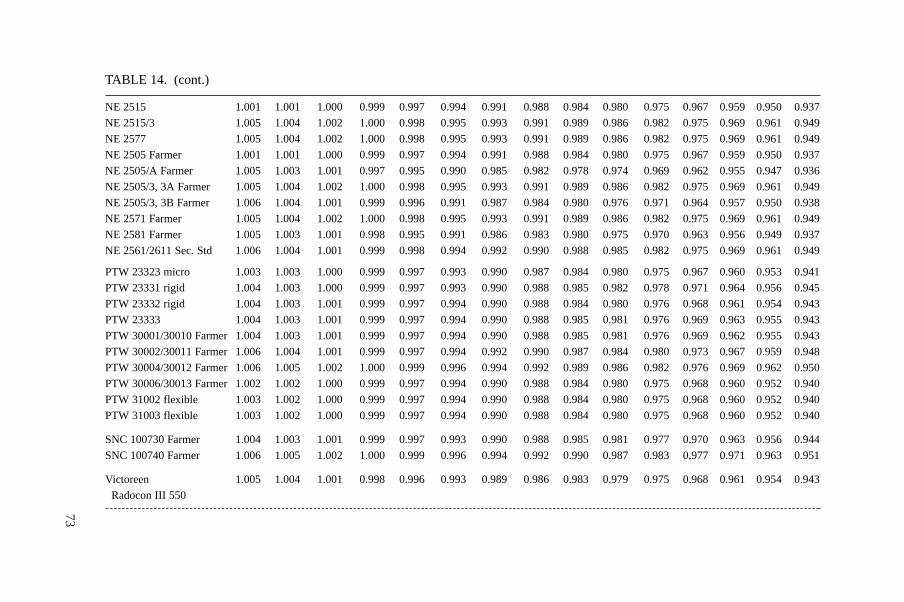
73
TABLE 14. (cont.)
NE 2515 1.001 1.001 1.000 0.999 0.997 0.994 0.991 0.988 0.984 0.980 0.975 0.967 0.959 0.950 0.937
NE 2515/3 1.005 1.004 1.002 1.000 0.998 0.995 0.993 0.991 0.989 0.986 0.982 0.975 0.969 0.961 0.949
NE 2577 1.005 1.004 1.002 1.000 0.998 0.995 0.993 0.991 0.989 0.986 0.982 0.975 0.969 0.961 0.949
NE 2505 Farmer 1.001 1.001 1.000 0.999 0.997 0.994 0.991 0.988 0.984 0.980 0.975 0.967 0.959 0.950 0.937
NE 2505/A Farmer 1.005 1.003 1.001 0.997 0.995 0.990 0.985 0.982 0.978 0.974 0.969 0.962 0.955 0.947 0.936
NE 2505/3, 3A Farmer 1.005 1.004 1.002 1.000 0.998 0.995 0.993 0.991 0.989 0.986 0.982 0.975 0.969 0.961 0.949
NE 2505/3, 3B Farmer 1.006 1.004 1.001 0.999 0.996 0.991 0.987 0.984 0.980 0.976 0.971 0.964 0.957 0.950 0.938
NE 2571 Farmer 1.005 1.004 1.002 1.000 0.998 0.995 0.993 0.991 0.989 0.986 0.982 0.975 0.969 0.961 0.949
NE 2581 Farmer 1.005 1.003 1.001 0.998 0.995 0.991 0.986 0.983 0.980 0.975 0.970 0.963 0.956 0.949 0.937
NE 2561/2611 Sec. Std 1.006 1.004 1.001 0.999 0.998 0.994 0.992 0.990 0.988 0.985 0.982 0.975 0.969 0.961 0.949
PTW 23323 micro 1.003 1.003 1.000 0.999 0.997 0.993 0.990 0.987 0.984 0.980 0.975 0.967 0.960 0.953 0.941
PTW 23331 rigid 1.004 1.003 1.000 0.999 0.997 0.993 0.990 0.988 0.985 0.982 0.978 0.971 0.964 0.956 0.945
PTW 23332 rigid 1.004 1.003 1.001 0.999 0.997 0.994 0.990 0.988 0.984 0.980 0.976 0.968 0.961 0.954 0.943
PTW 23333 1.004 1.003 1.001 0.999 0.997 0.994 0.990 0.988 0.985 0.981 0.976 0.969 0.963 0.955 0.943
PTW 30001/30010 Farmer 1.004 1.003 1.001 0.999 0.997 0.994 0.990 0.988 0.985 0.981 0.976 0.969 0.962 0.955 0.943
PTW 30002/30011 Farmer 1.006 1.004 1.001 0.999 0.997 0.994 0.992 0.990 0.987 0.984 0.980 0.973 0.967 0.959 0.948
PTW 30004/30012 Farmer 1.006 1.005 1.002 1.000 0.999 0.996 0.994 0.992 0.989 0.986 0.982 0.976 0.969 0.962 0.950
PTW 30006/30013 Farmer 1.002 1.002 1.000 0.999 0.997 0.994 0.990 0.988 0.984 0.980 0.975 0.968 0.960 0.952 0.940
PTW 31002 flexible 1.003 1.002 1.000 0.999 0.997 0.994 0.990 0.988 0.984 0.980 0.975 0.968 0.960 0.952 0.940
PTW 31003 flexible 1.003 1.002 1.000 0.999 0.997 0.994 0.990 0.988 0.984 0.980 0.975 0.968 0.960 0.952 0.940
SNC 100730 Farmer 1.004 1.003 1.001 0.999 0.997 0.993 0.990 0.988 0.985 0.981 0.977 0.970 0.963 0.956 0.944
SNC 100740 Farmer 1.006 1.005 1.002 1.000 0.999 0.996 0.994 0.992 0.990 0.987 0.983 0.977 0.971 0.963 0.951
Victoreen 1.005 1.004 1.001 0.998 0.996 0.993 0.989 0.986 0.983 0.979 0.975 0.968 0.961 0.954 0.943
Radocon III 550
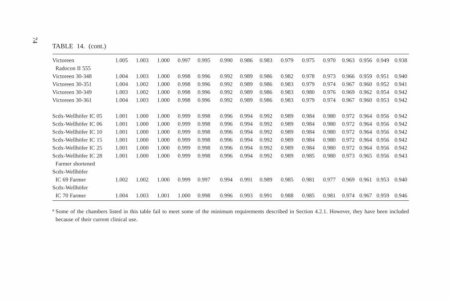
74
TABLE 14. (cont.)
Victoreen 1.005 1.003 1.000 0.997 0.995 0.990 0.986 0.983 0.979 0.975 0.970 0.963 0.956 0.949 0.938
Radocon II 555
Victoreen 30-348 1.004 1.003 1.000 0.998 0.996 0.992 0.989 0.986 0.982 0.978 0.973 0.966 0.959 0.951 0.940
Victoreen 30-351 1.004 1.002 1.000 0.998 0.996 0.992 0.989 0.986 0.983 0.979 0.974 0.967 0.960 0.952 0.941
Victoreen 30-349 1.003 1.002 1.000 0.998 0.996 0.992 0.989 0.986 0.983 0.980 0.976 0.969 0.962 0.954 0.942
Victoreen 30-361 1.004 1.003 1.000 0.998 0.996 0.992 0.989 0.986 0.983 0.979 0.974 0.967 0.960 0.953 0.942
Scdx-Wellhöfer IC 05 1.001 1.000 1.000 0.999 0.998 0.996 0.994 0.992 0.989 0.984 0.980 0.972 0.964 0.956 0.942
Scdx-Wellhöfer IC 06 1.001 1.000 1.000 0.999 0.998 0.996 0.994 0.992 0.989 0.984 0.980 0.972 0.964 0.956 0.942
Scdx-Wellhöfer IC 10 1.001 1.000 1.000 0.999 0.998 0.996 0.994 0.992 0.989 0.984 0.980 0.972 0.964 0.956 0.942
Scdx-Wellhöfer IC 15 1.001 1.000 1.000 0.999 0.998 0.996 0.994 0.992 0.989 0.984 0.980 0.972 0.964 0.956 0.942
Scdx-Wellhöfer IC 25 1.001 1.000 1.000 0.999 0.998 0.996 0.994 0.992 0.989 0.984 0.980 0.972 0.964 0.956 0.942
Scdx-Wellhöfer IC 28 1.001 1.000 1.000 0.999 0.998 0.996 0.994 0.992 0.989 0.985 0.980 0.973 0.965 0.956 0.943
Farmer shortened
Scdx-Wellhöfer
IC 69 Farmer 1.002 1.002 1.000 0.999 0.997 0.994 0.991 0.989 0.985 0.981 0.977 0.969 0.961 0.953 0.940
Scdx-Wellhöfer
IC 70 Farmer 1.004 1.003 1.001 1.000 0.998 0.996 0.993 0.991 0.988 0.985 0.981 0.974 0.967 0.959 0.946
a Some of the chambers listed in this table fail to meet some of the minimum requirements described in Section 4.2.1. However, they have been included
because of their current clinical use.
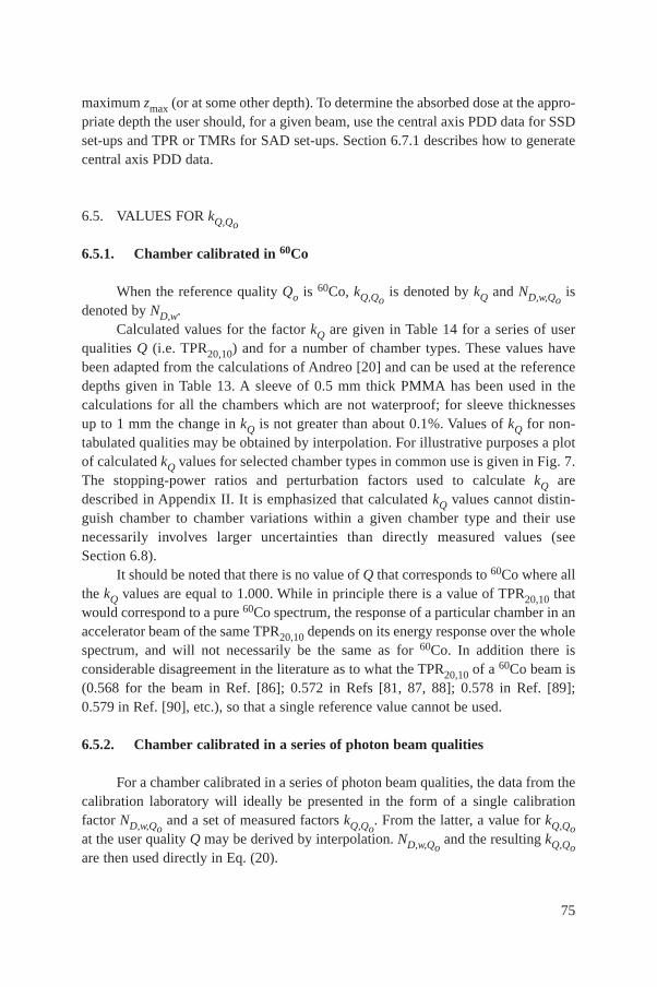
75
maximum zmax (or at some other depth). To determine the absorbed dose at the appro-priate depth the user should, for a given beam, use the central axis PDD data for SSDset-ups and TPR or TMRs for SAD set-ups. Section 6.7.1 describes how to generatecentral axis PDD data.
6.5. VALUES FOR kQ,Qo
6.5.1. Chamber calibrated in 60Co
When the reference quality Qo is 60Co, kQ,Qois denoted by kQ and ND,w,Qo
isdenoted by ND,w.
Calculated values for the factor kQ are given in Table 14 for a series of userqualities Q (i.e. TPR20,10) and for a number of chamber types. These values havebeen adapted from the calculations of Andreo [20] and can be used at the referencedepths given in Table 13. A sleeve of 0.5 mm thick PMMA has been used in thecalculations for all the chambers which are not waterproof; for sleeve thicknessesup to 1 mm the change in kQ is not greater than about 0.1%. Values of kQ for non-tabulated qualities may be obtained by interpolation. For illustrative purposes a plotof calculated kQ values for selected chamber types in common use is given in Fig. 7.The stopping-power ratios and perturbation factors used to calculate kQ aredescribed in Appendix II. It is emphasized that calculated kQ values cannot distin-guish chamber to chamber variations within a given chamber type and their usenecessarily involves larger uncertainties than directly measured values (seeSection 6.8).
It should be noted that there is no value of Q that corresponds to 60Co where allthe kQ values are equal to 1.000. While in principle there is a value of TPR20,10 thatwould correspond to a pure 60Co spectrum, the response of a particular chamber in anaccelerator beam of the same TPR20,10 depends on its energy response over the wholespectrum, and will not necessarily be the same as for 60Co. In addition there isconsiderable disagreement in the literature as to what the TPR20,10 of a 60Co beam is(0.568 for the beam in Ref. [86]; 0.572 in Refs [81, 87, 88]; 0.578 in Ref. [89];0.579 in Ref. [90], etc.), so that a single reference value cannot be used.
6.5.2. Chamber calibrated in a series of photon beam qualities
For a chamber calibrated in a series of photon beam qualities, the data from thecalibration laboratory will ideally be presented in the form of a single calibrationfactor ND,w,Qo
and a set of measured factors kQ,Qo. From the latter, a value for kQ,Qo
at the user quality Q may be derived by interpolation. ND,w,Qoand the resulting kQ,Qo
are then used directly in Eq. (20).
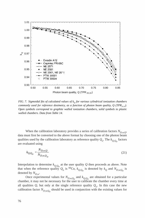
76
When the calibration laboratory provides a series of calibration factors ND,w,Q,data must first be converted to the above format by choosing one of the photon beamqualities used by the calibration laboratory as reference quality Qo. The kQ,Qo
factorsare evaluated using
(21)
Interpolation to determine kQ,Qoat the user quality Q then proceeds as above. Note
that when the reference quality Qo is 60Co, kQ,Qois denoted by kQ and ND,w,Qo
isdenoted by ND,w.
Once experimental values for ND,w,Qoand kQ,Qo
are obtained for a particularchamber, it may not be necessary for the user to calibrate the chamber every time atall qualities Q, but only at the single reference quality Qo. In this case the newcalibration factor ND,w,Qo
should be used in conjunction with the existing values for
D,w,QQ,Qo
D,w,Qo
Nk =
N
FIG. 7. Sigmoidal fits of calculated values of kQ for various cylindrical ionization chamberscommonly used for reference dosimetry, as a function of photon beam quality, Q (TPR20,10).Open symbols correspond to graphite walled ionization chambers, solid symbols to plasticwalled chambers. Data from Table 14.
Photon beam quality, Q (TPR 20,10 )
0.50 0.55 0.60 0.65 0.70 0.75 0.80 0.85
kQ
0.93
0.94
0.95
0.96
0.97
0.98
0.99
1.00
1.01
77
kQ,Qoand the quality dependence of that chamber (kQ,Qo
values) needs to be verifiedevery third calibration cycle of the chamber or if the user suspects that the chamberhas been damaged. The single calibration does not need to be performed at the samelaboratory where the experimental kQ,Qo
values were measured. Note, however, thatthis procedure should not be repeated more than twice in succession; the chambershould be recalibrated at all qualities at least every six years.
6.5.3. Chamber calibrated at Qo with generic experimental kQ,Qovalues
Calibration laboratories sometimes provide generic experimental kQ,Qovalues
measured for a particular chamber type, together with a single experimental ND,w,Qofor
the user chamber where the reference quality Qo is usually 60Co. Only those genericvalues of kQ,Qo
that have been obtained by a standards laboratory from a large sampleof ionization chambers and whose standard deviation of chamber to chamber differ-ences is small are recommended for use in this Code of Practice (see Section 4.1).Generic values not determined by a standards laboratory are not recommended.
It is emphasized that directly measured values of kQ,Qofor an individual
chamber within a given chamber type are the preferred choice in this Code ofPractice, followed by the calculated values of kQ,Qo
for a given chamber type given inTable 14. Note that if generic values for kQ,Qo
(measured for a particular chambertype) exist, these should be used only if they meet the criteria expressed inSection 4.1.
6.6. CROSS-CALIBRATION OF FIELD IONIZATION CHAMBERS
As noted in Section 6.2.1, a field chamber may be cross-calibrated against acalibrated reference chamber at the reference quality Qo. The chambers are comparedby alternately placing the chambers in a water phantom with their reference points atzref (a side by side chamber intercomparison is a possible alternate configuration).The calibration factor in terms of absorbed dose to water for the field ionizationchamber is given by
(22)
where Mref and Mfield are the meter readings per monitor unit (MU) for the referenceand field chambers, respectively, corrected for the influence quantities temperature andpressure, electrometer calibration, polarity effect and ion recombination as describedin the worksheet (see also Section 4.4.3) and N ref
D,w,Qois the calibration factor in terms
field refref
fieldD,w,Q D,w,Qo o
MN = N
M
of absorbed dose to water for the reference chamber. Preferably, the readings Mref andMfield should actually be the averages and , where (Mref /Mem)iand (Mfield/Mem)i are, respectively, the ratios of the reading of the reference detectorand the field instrument to the reading of an external monitor. The external monitorshould preferably be positioned inside the phantom approximately at the depth zref butat a distance of 3–4 cm away from the chamber centre along the major axis in thetransverse plane of the beam. Note that in the case of a side by side measurement anexternal monitor is not needed provided that the beam profile is adequately uniform.
The field chamber with the calibration factor N fieldD,w,Qo
may be used subsequentlyfor the determination of absorbed dose to water in the user beam using the procedureof Section 6.4.2, where ND,w,Qo
is replaced by N fieldD,w,Qo
.
6.7. MEASUREMENTS UNDER NON-REFERENCE CONDITIONS
Clinical dosimetry requires the measurements of PDD, TPRs or TMRs, isodosedistributions, transverse beam profiles and output factors as a function of field sizeand shape for both reference and non-reference conditions. Such measurementsshould be made for all possible combinations of energy, field size and SSD or SADused for radiotherapy treatment.
6.7.1. Central axis depth dose distributions
All measurements should follow the recommendations given in Section 4.2regarding choices for phantoms and dosimeters, although other types of detectors canalso be used. For measurements of depth ionization curves, plane-parallel ionizationchambers are recommended. If a cylindrical ionization chamber is used instead, then theeffective point of measurement of the chamber must be taken into account. This requiresthat the complete depth ionization distribution be shifted towards the surface a distanceequal to 0.6 rcyl [17, 21] where rcyl is the cavity radius of the cylindrical ionizationchamber. To make accurate measurements in the buildup region, extrapolation cham-bers or well guarded fixed separation plane-parallel chambers should be used. Attentionshould be paid to the use of certain solid state detectors (some types of diodes and dia-mond detectors) to measure depth dose distributions (see, for instance, Ref. [21]); onlya solid state detector whose response has been regularly verified against a referencedetector (ionization chamber) should be selected for these measurements.
Since the stopping power ratios and perturbation effects can be assumed to areasonable accuracy to be independent of depth for a given beam quality and fieldsize, relative ionization distributions can be used as relative distributions of absorbeddose, at least for depths at and beyond the depth of dose maximum.
field emM /Mref emM /M
78
6.7.2. Output factors
The output factor may be determined as the ratio of corrected dosimeter read-ings measured under a given set of non-reference conditions to that measured underreference conditions. These measurements are typically done at the depth of max-imum dose or at the reference depth [77] and corrected to the depth of maximum doseusing PDD (or TMR). When output factors are measured in open as well as wedgedbeams, special attention should be given to the uniformity of the radiation fluenceover the chamber cavity. This is especially important for field sizes smaller than5 cm × 5 cm. Some accelerators have very pronounced V shaped photon beam pro-files which usually vary with depth and field size. For large detectors it may be diffi-cult to correct for this variation accurately. Thimble chambers with large cavity lengthand plane-parallel chambers with large collecting electrodes (see Section 4.2.1 forchamber requirements) should therefore be avoided in situations where the beamshave pronounced V shaped profiles.
In wedged photon beams the radiation intensity varies strongly in the directionof the wedge. For output measurements in such beams the detector dimension in thewedge direction should be as small as possible. A small thimble chamber aligned withits axis perpendicular to the wedge direction is recommended. The coincidence of thecentral axes of the beam, the collimator and the wedge should be ensured prior tomaking the output measurements.
6.8. ESTIMATED UNCERTAINTY IN THE DETERMINATION OF ABSORBED DOSE TO WATER UNDER REFERENCE CONDITIONS
When a reference dosimeter is used for the determination of absorbed dose towater in the user beam, the uncertainties in the different physical quantities or proce-dures that contribute to the dose determination can be divided into two steps. Step 1considers uncertainties up to the calibration of the user reference dosimeter in termsof ND,w at the standards laboratory. Step 2 deals with the calibration of the user beamand includes the uncertainties associated with the measurements at the reference pointin a water phantom. Step 2 also includes the uncertainty of the kQ value. The uncer-tainties of the factors that contribute to the uncertainty of calculated kQ values can befound in Appendix II. Combining the uncertainties in quadrature in the various stepsyields the combined standard uncertainty for the determination of the absorbed doseto water at the reference point.
An estimate of the uncertainties in the calibration of a high energy photon beamis given in Table 15. When the calibration of the reference dosimeter is carried out inthe 60Co beam of an SSDL, the combined standard uncertainty in Dw is estimated tobe typically about 1.5%, based on calculated values of kQ. This estimate may vary
79
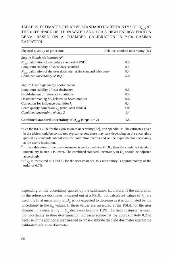
80
depending on the uncertainty quoted by the calibration laboratory. If the calibrationof the reference dosimeter is carried out at a PSDL, but calculated values of kQ areused, the final uncertainty in Dw is not expected to decrease as it is dominated by theuncertainty in the kQ values. If these values are measured at the PSDL for the userchamber, the uncertainty in Dw decreases to about 1.2%. If a field dosimeter is used,the uncertainty in dose determination increases somewhat (by approximately 0.2%)because of the additional step needed to cross-calibrate the field dosimeter against thecalibrated reference dosimeter.
TABLE 15. ESTIMATED RELATIVE STANDARD UNCERTAINTY a OF Dw,Q ATTHE REFERENCE DEPTH IN WATER AND FOR A HIGH ENERGY PHOTONBEAM, BASED ON A CHAMBER CALIBRATION IN 60Co GAMMARADIATION
Physical quantity or procedure Relative standard uncertainty (%)
Step 1: Standards laboratoryb
ND,w calibration of secondary standard at PSDL 0.5Long term stability of secondary standard 0.1ND,w calibration of the user dosimeter at the standard laboratory 0.4Combined uncertainty of step 1 0.6
Step 2: User high energy photon beamLong term stability of user dosimeter 0.3Establishment of reference conditions 0.4Dosimeter reading MQ relative to beam monitor 0.6Correction for influence quantities ki 0.4Beam quality correction kQ (calculated values) 1.0c
Combined uncertainty of step 2 1.4
Combined standard uncertainty of Dw,Q (steps 1 + 2) 1.5
a See the ISO Guide for the expression of uncertainty [32], or Appendix IV. The estimates givenin the table should be considered typical values; these may vary depending on the uncertaintyquoted by standards laboratories for calibration factors and on the experimental uncertaintyat the user’s institution.
b If the calibration of the user dosimeter is performed at a PSDL, then the combined standarduncertainty in step 1 is lower. The combined standard uncertainty in Dw should be adjustedaccordingly.
c If kQ is measured at a PSDL for the user chamber, this uncertainty is approximately of theorder of 0.7%.
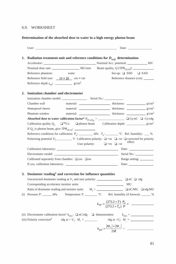
81
6.9. WORKSHEET
Determination of the absorbed dose to water in a high energy photon beam
User: ____________________________________________________ Date: _______________
1. Radiation treatment unit and reference conditions for Dw,Q determination
Accelerator: Nominal Acc. potential: MV
Nominal dose rate: MU/min Beam quality, Q (TPR20,10):
Reference phantom: water Set-up: ❏ SSD ❏ SAD
Reference field size: cm × cm Reference distance (cm):
Reference depth zref: ___________ g/cm2
2. Ionization chamber and electrometer
Ionization chamber model: ________________ Serial No.: ____________
Chamber wall material: thickness: g/cm2
Waterproof sleeve material: thickness: g/cm2
Phantom window material: thickness: g/cm2
Absorbed dose to water calibration factora ND,w,Qo= _________________ ❏ Gy/nC ❏ Gy/rdg
Calibration quality Qo ❏ 60Co ❏ photon beam Calibration depth: ____________ g/cm2
If Qo is photon beam, give TPR20,10: _____________
Reference conditions for calibration Po: _________ kPa To: ________ °C Rel. humidity: ___ %
Polarizing potential Vl:__________ V Calibration polarity: ❏ +ve ❏ –ve ❏ corrected for polarity
User polarity: ❏ +ve ❏ –veeffect
Calibration laboratory: Date:
Electrometer model: Serial No.:
Calibrated separately from chamber: ❏ yes ❏ no Range setting:
If yes, calibration laboratory: Date:
3. Dosimeter readingb and correction for influence quantities
Uncorrected dosimeter reading at V1 and user polarity: ❏ nC ❏ rdg
Corresponding accelerator monitor units: MU
Ratio of dosimeter reading and monitor units: M1 = ❏ nC/MU ❏ rdg/MU
(i) Pressure P: ______ kPa Temperature T: ________ °C Rel. humidity (if known): ______ %
(ii) Electrometer calibration factorc kelec: ❏ nC/rdg ❏ dimensionless kelec =
(iii) Polarity correctiond rdg at + V1: M+ = ________ rdg at –V1: M_ =
= _________________kM M
Mpol =++ -
2
kT
T
P
PTPo
o= ++
=( . )
( . )
273 2
273 2
10 × 10
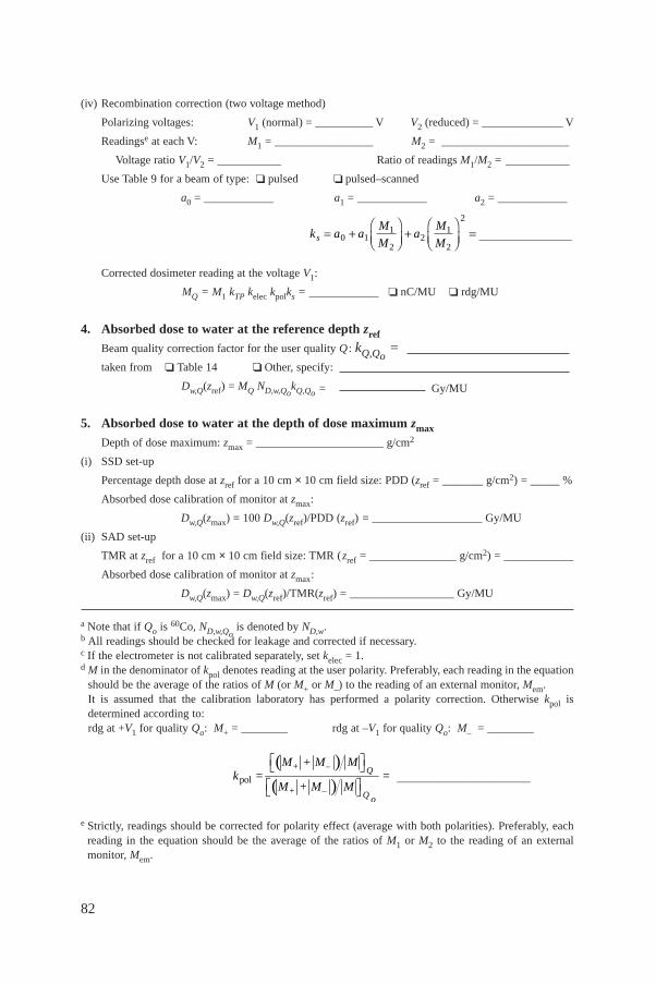
82
(iv) Recombination correction (two voltage method)
Polarizing voltages: V1 (normal) = __________ V V2 (reduced) = ______________ V
Readingse at each V: M1 = _________________ M2 = ______________________
Voltage ratio V1/V2 = ___________ Ratio of readings M1/M2 = ___________
Use Table 9 for a beam of type: ❏ pulsed ❏ pulsed–scanned
a0 = ____________ a1 = ____________ a2 = ____________
________________
Corrected dosimeter reading at the voltage V1:
MQ = M1 kTP kelec kpolks = ____________ ❏ nC/MU ❏ rdg/MU
4. Absorbed dose to water at the reference depth zref
Beam quality correction factor for the user quality Q : kQ,Qo=
taken from ❏ Table 14 ❏ Other, specify:
Dw,Q(zref) = MQ ND,w,QokQ,Qo = Gy/MU
5. Absorbed dose to water at the depth of dose maximum zmax
Depth of dose maximum: zmax = ______________________ g/cm2
(i) SSD set-up
Percentage depth dose at zref for a 10 cm × 10 cm field size: PDD (zref = _______ g/cm2) = _____ %
Absorbed dose calibration of monitor at zmax:
Dw,Q(zmax) = 100 Dw,Q(zref)/PDD (zref) = ___________________ Gy/MU
(ii) SAD set-up
TMR at zref for a 10 cm × 10 cm field size: TMR (zref = _______________ g/cm2) = ____________
Absorbed dose calibration of monitor at zmax:
Dw,Q(zmax) = Dw,Q(zref)/TMR(zref) = __________________ Gy/MU
a Note that if Qo is 60Co, ND,w,Qois denoted by ND,w.
b All readings should be checked for leakage and corrected if necessary.c If the electrometer is not calibrated separately, set kelec = 1.d M in the denominator of kpol denotes reading at the user polarity. Preferably, each reading in the equation
should be the average of the ratios of M (or M+ or M–) to the reading of an external monitor, Mem.It is assumed that the calibration laboratory has performed a polarity correction. Otherwise kpol isdetermined according to:rdg at +V1 for quality Qo: M+ = ________ rdg at –V1 for quality Qo: M– = ________
_______________________
e Strictly, readings should be corrected for polarity effect (average with both polarities). Preferably, eachreading in the equation should be the average of the ratios of M1 or M2 to the reading of an externalmonitor, Mem.
( )( )pol
+ – Q
+ – Q o
M + M Mk = =
M + M M
È ˘Î ˚È ˘Î ˚
k a aM
Ma
M
Ms = +ÊËÁ
ˆ¯̃
+ÊËÁ
ˆ¯̃
=0 11
22
1
2
2
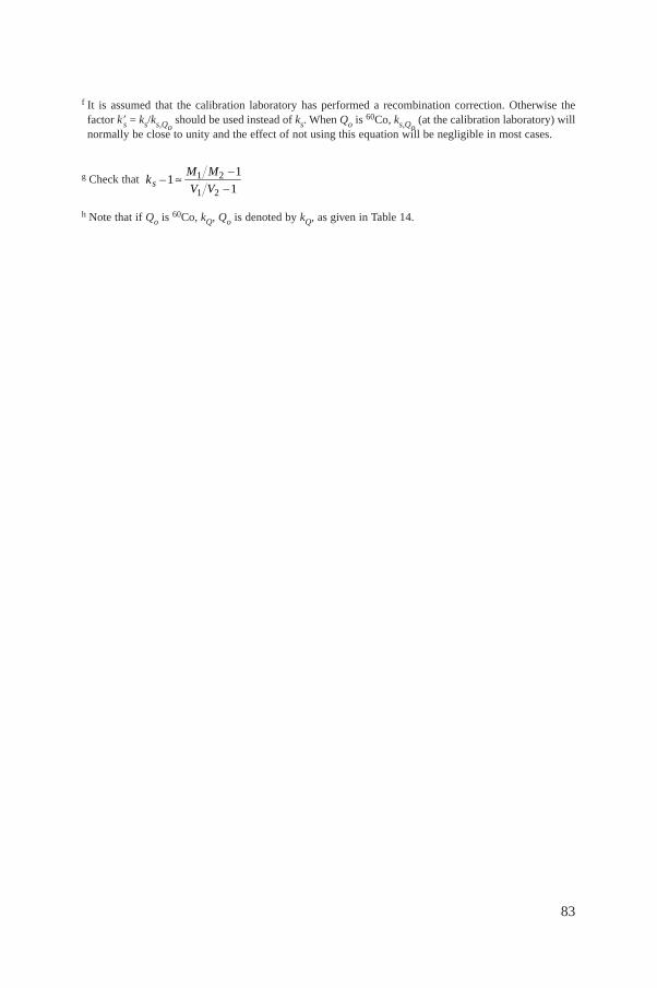
83
f It is assumed that the calibration laboratory has performed a recombination correction. Otherwise thefactor k′s = ks/ks,Qo
should be used instead of ks. When Qo is 60Co, ks,Qo(at the calibration laboratory) will
normally be close to unity and the effect of not using this equation will be negligible in most cases.
g Check that
h Note that if Qo is 60Co, kQ, Qo is denoted by kQ, as given in Table 14.
1 2
1 2
11
1sM M –
k –V V –
ª
84
7. CODE OF PRACTICE FORHIGH ENERGY ELECTRON BEAMS
7.1. GENERAL
This section provides a Code of Practice for reference dosimetry (beamcalibration) and recommendations for relative dosimetry in clinical electron beamswith energies in the range from 3–50 MeV. It is based upon a calibration factor interms of absorbed dose to water ND,w,Qo
for a dosimeter in a reference beam of qualityQo. This reference quality may be either 60Co gamma radiation or an electron beamquality. In the latter case the dosimeter may be calibrated either directly at a standardslaboratory or by cross-calibration in a clinical electron beam.
Aside from having its foundation on standards of absorbed dose, the mostsignificant change from current practice is the use of a new reference depth. Thisdepth has been shown to reduce significantly the influence of spectral differencesbetween different accelerators as well as that of electron and photon contamination inclinical electron beams [21, 91]. For simplicity, beam qualities and all factors depen-dent on beam quality (including the new reference depth) are expressed in terms ofthe half-value depth R50 rather than beam energy. This change parallels the longstanding practice in photon dosimetry, where beam qualities are expressed in termsof the penetration of the beam.
7.2. DOSIMETRY EQUIPMENT
7.2.1. Ionization chambers
The recommendations regarding ionization chambers given in Section 4.2.1should be followed. Plane-parallel chambers are the recommended type for all beamqualities and must be used for beam qualities R50 < 4 g/cm2 (Eo � 10 MeV).26 Ideally,the chamber should be calibrated in an electron beam, either directly at a standardslaboratory or by cross-calibration in a clinical electron beam. The reference point forplane-parallel chambers is taken to be on the inner surface of the entrance window, at
26 The approximate relation Eo = 2.33 R50 is assumed, where Eo is the mean energy atthe phantom surface in MeV and R50 is expressed in g/cm2. The value stated for R50 takesprecedence over that stated for Eo.
85
the centre of the window. This point should be positioned at the point of interest inthe phantom. Chamber window thicknesses (in mm and in mg/cm2) for a variety ofplane-parallel chamber types are given in Table 4.
For beam qualities R50 ≥ 4 g/cm2 (Eo � 10 MeV) cylindrical chambers may beused. The reference point for cylindrical chambers is taken to be on the chamber axisat the centre of the cavity volume. For measurements in electron beams this referencepoint should be positioned a distance 0.5 rcyl deeper than the point of interest in thephantom, where rcyl is the radius of the air cavity.27 Values for rcyl for a variety ofcylindrical chamber types are given in Table 3.
7.2.2. Phantoms and chamber sleeves
The recommendations regarding phantoms and chamber sleeves given inSections 4.2.3 and 4.2.4 should be followed, both for determination of absorbed doseand for beam quality specification. Water is recommended as the reference mediumfor measurements in electron beams. The water phantom should extend to at least5 cm beyond all four sides of the largest field size employed at the depth of mea-surement. There should also be a margin of at least 5 g/cm2 beyond the maximumdepth of measurement.
In a horizontal electron beam, the window of the phantom should be of plasticand of thickness twin between 0.2 cm and 0.5 cm.28 The water equivalent thickness ofthe phantom window (in g/cm2) should be taken into account when positioning thechamber at the desired measurement depth. This thickness is calculated as the producttwin ρpl, where ρpl is the density of the plastic (in g/cm3). For the commonly usedplastics PMMA and clear polystyrene, the nominal values ρPMMA = 1.19 g/cm3 andρpolystyrene = 1.06 g/cm3 may be used [64].
Under certain circumstances and for beam qualities R50 < 4 g/cm2 (Eo �10 MeV), a plastic phantom may be used; all depths must then be appropriately scaled(see Sections 4.2.3 and 7.8).29
27 As with the concept of ‘effective point of measurement’ (see Section 1.6), positioningthe chamber in this way is used to avoid the need for a fluence gradient correction. This is ofparticular significance because, in common with Refs [17, 21], the reference depth as definedin this Code of Practice does not always coincide with that of the dose maximum.
28 A window of only a few millimetres in thickness may bow outwards slightly owing towater pressure on the inner surface. Any such effect should be accounted for when positioningthe chamber at the depth of interest, particularly in low energy electron beams.
29 Plastic phantoms can be used for routine quality assurance measurements, provided atransfer factor between plastic and water has been established at the time of beam calibration.
86
Plane-parallel chambers, if not inherently waterproof or supplied with a water-proof cover, should be used in a waterproof enclosure, preferably of PMMA or amaterial that matches the chamber walls. Ideally, there should be no more than 1 mmof added material in front of and behind the air cavity. Cylindrical chambers shouldbe used in a PMMA sleeve, preferably not thicker than 1.0 mm. The air gap betweenthe chamber wall and the sleeve should be sufficient (0.1–0.3 mm) to allow the airpressure in the chamber to follow the ambient air pressure. For both chamber types,the same (or similar) waterproofing should be used for the determination of absorbeddose to water at the user facility as was used for calibration at the standardslaboratory.
Strictly, when used in conjunction with the calculated values for kQ,Qogiven in
this section, the water equivalent thickness (in g/cm2) of the chamber wall and anywaterproofing material should be taken into account when positioning the chamber atthe point of interest. However, this is a very small effect and may be ignored inpractice. For general comments on the positioning of chambers, see Section 4.2.5.
7.3. BEAM QUALITY SPECIFICATION
7.3.1. Choice of beam quality index
For electron beams the beam quality index is the half-value depth in water R50.This is the depth in water (in g/cm2) at which the absorbed dose is 50% of its valueat the absorbed dose maximum, measured with a constant SSD of 100 cm and a fieldsize at the phantom surface of at least 10 cm × 10 cm for R50 ≤ 7 g/cm2 (Eo � 16 MeV)and at least 20 cm × 20 cm for R50 > 7 g/cm2 (Eo � 16 MeV). As noted in Ref. [21],some accelerators at high electron energies have an intrinsic poor homogeneity atlarge field sizes, which may improve at smaller field sizes as a result of electronsscattered from the collimator (or applicator, cones, etc.). In such cases a field sizesmaller than 20 cm × 20 cm may be used provided that R50 does not change by morethan around 0.1 g/cm2 from the value measured for a 20 cm × 20 cm field.
The choice of R50 as the beam quality index is a change from the currentpractice of specifying beam quality in terms of the mean energy at the phantomsurface Eo. As Eo is normally derived from R50, this change in beam quality index ismerely a simplification which avoids the need for a conversion to energy.
7.3.2. Measurement of beam quality
The reference conditions for the determination of R50 are given in Table 16. Forall beam qualities, the preferred choice of detector for the measurement of R50 is a
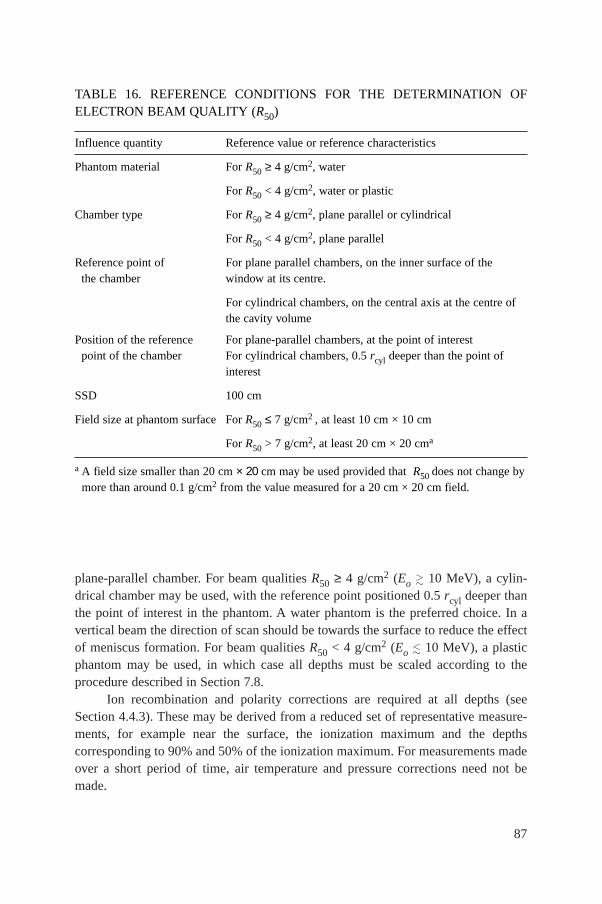
87
plane-parallel chamber. For beam qualities R50 ≥ 4 g/cm2 (Eo � 10 MeV), a cylin-drical chamber may be used, with the reference point positioned 0.5 rcyl deeper thanthe point of interest in the phantom. A water phantom is the preferred choice. In avertical beam the direction of scan should be towards the surface to reduce the effectof meniscus formation. For beam qualities R50 < 4 g/cm2 (Eo � 10 MeV), a plasticphantom may be used, in which case all depths must be scaled according to theprocedure described in Section 7.8.
Ion recombination and polarity corrections are required at all depths (seeSection 4.4.3). These may be derived from a reduced set of representative measure-ments, for example near the surface, the ionization maximum and the depthscorresponding to 90% and 50% of the ionization maximum. For measurements madeover a short period of time, air temperature and pressure corrections need not bemade.
TABLE 16. REFERENCE CONDITIONS FOR THE DETERMINATION OFELECTRON BEAM QUALITY (R50)
Influence quantity Reference value or reference characteristics
Phantom material For R50 ≥ 4 g/cm2, water
For R50 < 4 g/cm2, water or plastic
Chamber type For R50 ≥ 4 g/cm2, plane parallel or cylindrical
For R50 < 4 g/cm2, plane parallel
Reference point of For plane parallel chambers, on the inner surface of the the chamber window at its centre.
For cylindrical chambers, on the central axis at the centre of the cavity volume
Position of the reference For plane-parallel chambers, at the point of interestpoint of the chamber For cylindrical chambers, 0.5 rcyl deeper than the point of
interest
SSD 100 cm
Field size at phantom surface For R50 ≤ 7 g/cm2 , at least 10 cm × 10 cm
For R50 > 7 g/cm2, at least 20 cm × 20 cma
a A field size smaller than 20 cm × 20 cm may be used provided that R50 does not change bymore than around 0.1 g/cm2 from the value measured for a 20 cm × 20 cm field.
When using an ionization chamber, the measured quantity is the half-value ofthe depth ionization distribution in water, R50,ion. This is the depth in water (in g/cm2)at which the ionization current is 50% of its maximum value. The half-value of thedepth dose distribution in water R50 is obtained using [92]:
R50 = 1.029 R50,ion – 0.06 g/cm2 (R50,ion ≤ 10 g/cm2)(23)
R50 = 1.059 R50,ion – 0.37 g/cm2 (R50,ion > 10 g/cm2)
As an alternative to the use of an ionization chamber, other detectors (forexample diode, diamond, etc.) may be used to determine R50. In this case the usermust verify that the detector is suitable for depth dose measurements by test compar-isons with an ionization chamber at a set of representative beam qualities.
7.4. DETERMINATION OF ABSORBED DOSE TO WATER
7.4.1. Reference conditions
The reference conditions for determination of absorbed dose to water inelectron beams are given in Table 17. Because the precise choice of field size is notcritical [21], a convenient choice for the reference field size is that which is usedfor the normalization of output factors, subject to the constraint that it should notbe less than 10 cm × 10 cm at the phantom surface. The reference depth zref is givenby [91]
zref = 0.6 R50 – 0.1 g/cm2 (R50 in g/cm2) (24)
This depth is close to the depth of the absorbed dose maximum zmax at beamqualities R50 < 4 g/cm2 (Eo � 10 MeV), but at higher beam qualities is deeper thanzmax. It is recognized that this choice of reference depth may be less convenient thanthat recommended in Ref. [17], since for a given accelerator no two reference beamswill have the same reference depth. However, the new depth has been shown signif-icantly to reduce machine to machine variations in chamber calibration factors [91]and the accuracy gained justifies its use, particularly for plane-parallel chambertypes.
It should be noted that by recommending that reference dosimetry at higherenergies be conducted at a depth beyond zmax, the uncertainty arising from cavityperturbation effects for cylindrical chambers may be larger. In the worst case,around R50 = 5 g/cm2 (Eo around 12 MeV) the increased uncertainty is approxi-mately 0.3%.
88
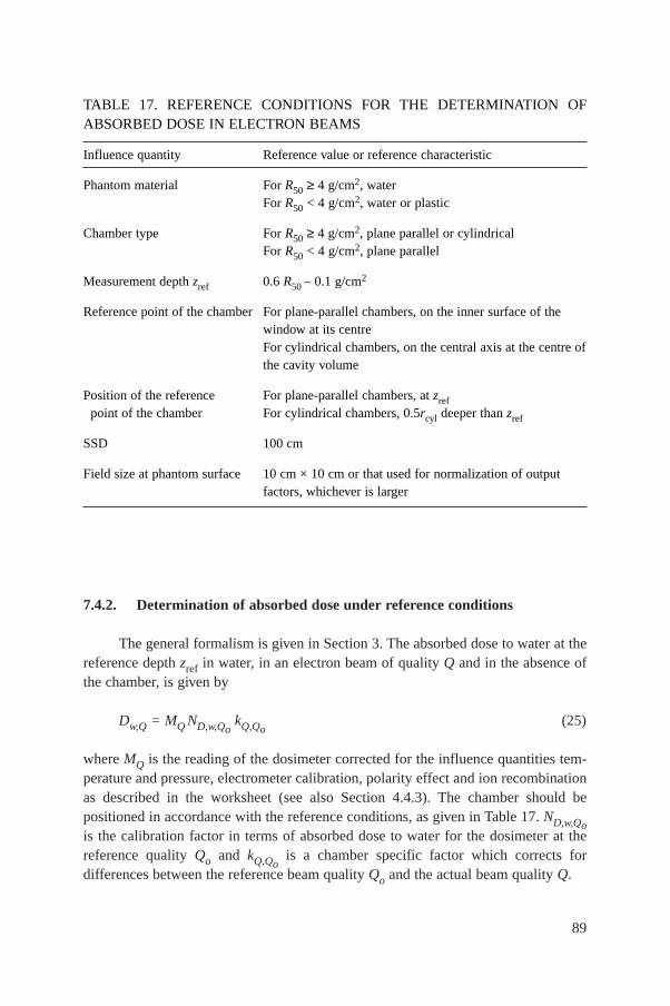
7.4.2. Determination of absorbed dose under reference conditions
The general formalism is given in Section 3. The absorbed dose to water at thereference depth zref in water, in an electron beam of quality Q and in the absence ofthe chamber, is given by
Dw,Q = MQ ND,w,QokQ,Qo
(25)
where MQ is the reading of the dosimeter corrected for the influence quantities tem-perature and pressure, electrometer calibration, polarity effect and ion recombinationas described in the worksheet (see also Section 4.4.3). The chamber should bepositioned in accordance with the reference conditions, as given in Table 17. ND,w,Qois the calibration factor in terms of absorbed dose to water for the dosimeter at thereference quality Qo and kQ,Qo
is a chamber specific factor which corrects fordifferences between the reference beam quality Qo and the actual beam quality Q.
89
TABLE 17. REFERENCE CONDITIONS FOR THE DETERMINATION OFABSORBED DOSE IN ELECTRON BEAMS
Influence quantity Reference value or reference characteristic
Phantom material For R50 ≥ 4 g/cm2, waterFor R50 < 4 g/cm2, water or plastic
Chamber type For R50 ≥ 4 g/cm2, plane parallel or cylindricalFor R50 < 4 g/cm2, plane parallel
Measurement depth zref 0.6 R50 – 0.1 g/cm2
Reference point of the chamber For plane-parallel chambers, on the inner surface of the window at its centreFor cylindrical chambers, on the central axis at the centre of the cavity volume
Position of the reference For plane-parallel chambers, at zrefpoint of the chamber For cylindrical chambers, 0.5rcyl deeper than zref
SSD 100 cm
Field size at phantom surface 10 cm × 10 cm or that used for normalization of output factors, whichever is larger
90
7.4.3. Absorbed dose at zmax
Clinical normalization most often takes place at the depth of the dose maximumzmax which, in this Code of Practice, does not always coincide with zref. To determinethe absorbed dose at zmax the user should, for a given beam, use the measured centralaxis depth dose distribution to convert the absorbed dose at zref to that at zmax. Themeasurement of depth dose distributions is discussed in Section 7.7.1.
7.5. VALUES FOR kQ,Qo
The general formalism is given in Section 3. The modified treatment of kQ,Qofor chambers cross-calibrated in a user electron beam, as described in Section 3.2.1,is dealt with in Section 7.6, which may also be applied to chambers calibrated directlyat a standards laboratory at a single electron beam quality. The stopping-power ratiosand perturbation factors used in the calculation of kQ,Qo
are described in Appendix II.
7.5.1. Chamber calibrated in 60Co
When the reference quality QO is 60Co, the factor kQ,Qois denoted by kQ.
Calculated values for kQ are given in Table 18 for a series of user qualities Q and fora number of chamber types; values for non-tabulated qualities may be obtained byinterpolation. These data are also presented in Figs 8 and 9 for plane-parallel andcylindrical chamber types, respectively. Note that if generic values for kQ,Qo(measured for a particular chamber type) exist, these should be used only if they meetthe criteria expressed in Section 4.1.
7.5.2. Chamber calibrated at a series of electron beam qualities
For a chamber calibrated at a series of electron beam qualities, the data fromthe calibration laboratory will ideally be presented as a single calibration factorND,w,Qo
determined in a reference electron beam of quality Qo and one or moremeasured factors kQ,Qo
corresponding to the other calibration qualities Q.However, if the calibration data are in the form of a set of calibration factors
ND,w,Q,, then one of the calibration qualities30 should be chosen as the referencecalibration quality Qo. The corresponding calibration factor is denoted ND,w,Qo
and the
30 The choice here is not critical; the quality corresponding to the ND,w,Q factor with thesmallest relative uncertainty is appropriate, otherwise a quality close to the middle of the range.
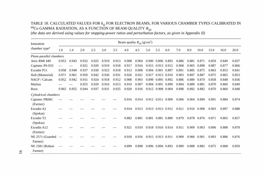
TABLE 18. CALCULATED VALUES FOR kQ FOR ELECTRON BEAMS, FOR VARIOUS CHAMBER TYPES CALIBRATED IN60Co GAMMA RADIATION, AS A FUNCTION OF BEAM QUALITY R50(the data are derived using values for stopping-power ratios and perturbation factors, as given in Appendix II)
Ionization Beam quality R50 (g/cm2)
chamber typea1.0 1.4 2.0 2.5 3.0 3.5 4.0 4.5 5.0 5.5 6.0 7.0 8.0 10.0 13.0 16.0 20.0
Plane-parallel chambers
Attix RMI 449 0.953 0.943 0.932 0.925 0.919 0.913 0.908 0.904 0.900 0.896 0.893 0.886 0.881 0.871 0.859 0.849 0.837
Capintec PS-033 — — 0.921 0.920 0.919 0.918 0.917 0.916 0.915 0.913 0.912 0.908 0.905 0.898 0.887 0.877 0.866
Exradin P11 0.958 0.948 0.937 0.930 0.923 0.918 0.913 0.908 0.904 0.901 0.897 0.891 0.885 0.875 0.863 0.853 0.841
Holt (Memorial) 0.971 0.961 0.950 0.942 0.936 0.931 0.926 0.921 0.917 0.913 0.910 0.903 0.897 0.887 0.875 0.865 0.853
NACP / Calcam 0.952 0.942 0.931 0.924 0.918 0.912 0.908 0.903 0.899 0.895 0.892 0.886 0.880 0.870 0.858 0.848 0.836
Markus — — 0.925 0.920 0.916 0.913 0.910 0.907 0.904 0.901 0.899 0.894 0.889 0.881 0.870 0.860 0.849
Roos 0.965 0.955 0.944 0.937 0.931 0.925 0.920 0.916 0.912 0.908 0.904 0.898 0.892 0.882 0.870 0.860 0.848
Cylindrical chambers
Capintec PR06C — — — — — — 0.916 0.914 0.912 0.911 0.909 0.906 0.904 0.899 0.891 0.884 0.874
(Farmer)
Exradin A2 — — — — — — 0.914 0.913 0.913 0.913 0.912 0.911 0.910 0.908 0.903 0.897 0.888
(Spokas)
Exradin T2 — — — — — — 0.882 0.881 0.881 0.881 0.880 0.879 0.878 0.876 0.871 0.865 0.857
(Spokas)
Exradin A12 — — — — — — 0.921 0.919 0.918 0.916 0.914 0.911 0.909 0.903 0.896 0.888 0.878
(Farmer)
NE 2571 (Guarded — — — — — — 0.918 0.916 0.915 0.913 0.911 0.909 0.906 0.901 0.893 0.886 0.876
Farmer)
NE 2581 (Robust — — — — — — 0.899 0.898 0.896 0.894 0.893 0.890 0.888 0.882 0.875 0.868 0.859
Farmer)91
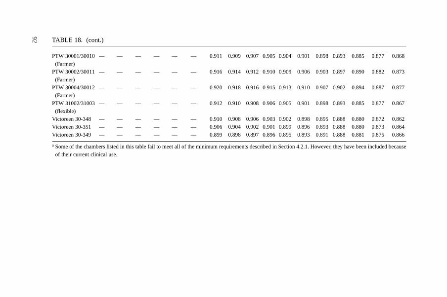
92 TABLE 18. (cont.)
PTW 30001/30010 — — — — — — 0.911 0.909 0.907 0.905 0.904 0.901 0.898 0.893 0.885 0.877 0.868
(Farmer)
PTW 30002/30011 — — — — — — 0.916 0.914 0.912 0.910 0.909 0.906 0.903 0.897 0.890 0.882 0.873
(Farmer)
PTW 30004/30012 — — — — — — 0.920 0.918 0.916 0.915 0.913 0.910 0.907 0.902 0.894 0.887 0.877
(Farmer)
PTW 31002/31003 — — — — — — 0.912 0.910 0.908 0.906 0.905 0.901 0.898 0.893 0.885 0.877 0.867
(flexible)
Victoreen 30-348 — — — — — — 0.910 0.908 0.906 0.903 0.902 0.898 0.895 0.888 0.880 0.872 0.862
Victoreen 30-351 — — — — — — 0.906 0.904 0.902 0.901 0.899 0.896 0.893 0.888 0.880 0.873 0.864
Victoreen 30-349 — — — — — — 0.899 0.898 0.897 0.896 0.895 0.893 0.891 0.888 0.881 0.875 0.866
a Some of the chambers listed in this table fail to meet all of the minimum requirements described in Section 4.2.1. However, they have been included because
of their current clinical use.
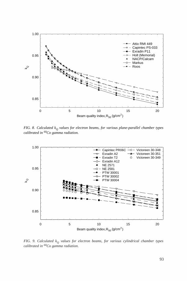
93
FIG. 9. Calculated kQ values for electron beams, for various cylindrical chamber typescalibrated in 60Co gamma radiation.
k Q
50 10 15 20
0.85
0.90
0.95
1.00
Beam quality index, R50 (g/cm2)
Capintec PR06C Exradin A2 Exradin T2 Exradin A12 NE 2571 NE 2581 PTW 30001 PTW 30002 PTW 30004
Victoreen 30-348 Victoreen 30-351 Victoreen 30-349
FIG. 8. Calculated kQ values for electron beams, for various plane-parallel chamber typescalibrated in 60Co gamma radiation.
k Q
0 5 10 15 20
0.85
0.90
0.95
1.00
Attix RMI 449 Capintec PS-033 Exradin P11 Holt (Memorial) NACP/Calcam Markus Roos
Beam quality index, R50 (g/cm2)
94
remaining calibration factors ND,w,Q are expressed as a series of factors kQ,Qousing
the relation
(26)
If the quality of the user beam Q does not match any of the calibration qualities, thevalue for kQ,Qo
to be used in Eq. (25) can be obtained by interpolation.A chamber calibrated at a series of beam qualities may be subsequently recali-
brated at only the reference calibration quality Qo. In this case, the new value forND,w,Qo
should be used in conjunction with the values for kQ,Qomeasured previously.
Note, however, that this procedure should not be repeated more than twice in succes-sion; the chamber should be recalibrated at all qualities at least every six years31, orif the user suspects that the chamber has been damaged.
7.6. CROSS-CALIBRATION OF IONIZATION CHAMBERS
Cross-calibration refers to the calibration of a user chamber by direct compar-ison in a suitable user beam against a reference chamber that has previously beencalibrated. A particular example of this is the cross-calibration of a plane-parallelchamber for use in electron beams against a reference cylindrical chamber calibratedin 60Co gamma radiation. Despite the additional step, such a cross-calibration gener-ally results in a determination of absorbed dose to water using the plane-parallelchamber that is more reliable than that achieved by the use of a plane-parallelchamber calibrated directly in 60Co, mainly because problems associated with thepwall correction for plane-parallel chambers in 60Co, entering into the determinationof kQ,Qo
, are avoided. The modified kQ,Qofactors to be used with a cross-calibrated
chamber are described in Section 3.2.1.
7.6.1. Cross-calibration procedure
The highest energy electron beam available should be used; R50 > 7 g/cm2
(Eo � 16 MeV) is recommended. The reference chamber and the chamber to be
D,w,QQ,Qo
D,w,Qo
Nk =
N
31 As noted in Section 4.3, this procedure should not be used for chambers whosestability has not been demonstrated over a period exceeding five years.
calibrated are compared by alternately positioning each at the reference depth zref inwater in accordance with the reference conditions for each (see Table 17). Thecalibration factor in terms of absorbed dose to water for the chamber under calibra-tion, at the cross-calibration quality Qcross, is given by
(27)
where M refQcross
and MxQcross
are the dosimeter readings for the reference chamber andthe chamber under calibration, respectively, corrected for the influence quantitiestemperature and pressure, electrometer calibration, polarity effect and ion recombi-nation as described in Section 4.4.3. N ref
D,w,Qois the calibration factor in terms of
absorbed dose to water for the reference chamber at quality Qo and krefQcross,Qo
is thebeam quality correction factor for the reference chamber.
In practice, to minimize the effect of any variation in the accelerator output, thereadings M ref
Qcrossand M ref
Qcrossshould be the averages and
respectively, measured relative to an external monitor. The external monitor shouldideally be positioned inside the phantom at the reference depth zref, but displacedlaterally a distance of 3 or 4 cm from the chamber centre.
Normally, the calibration quality Qo for the reference chamber will be 60Co andthe value for kref
Qcross,Qois derived from Table 18. In the event that Qo is a high energy
electron beam, the value for krefQcross,Qo
must be derived using the procedure ofSection 3.2.1:
(28)
where krefQcross Qint
and krefQo, Qint
are taken from Table 19.
7.6.2. Subsequent use of a cross-calibrated chamber
The cross-calibrated chamber with calibration factor N xD,w,Qcross
may be usedsubsequently for the determination of absorbed dose in a user beam of quality Q usingthe basic Eq. (25):
Dw,Q = MxQ Nx
D,w,Qcrosskx
Q,Qcross (29)
refref cross int
crossint
refQ ,Q
Q ,QoQ ,Qo
kk =
k
emcross cross
xQ QM /Mref
cross crossx
Q QM /M
refref refcross
cross crosscross
QxD,w,Q D,w,Q Q ,Qo ox
Q
MN = N k
M
95
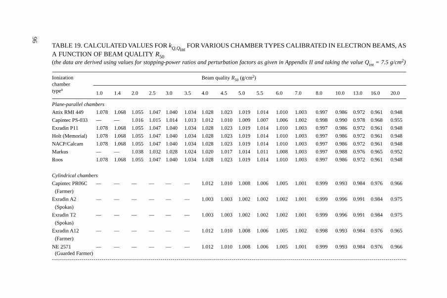
96
TABLE 19. CALCULATED VALUES FOR kQ,QintFOR VARIOUS CHAMBER TYPES CALIBRATED IN ELECTRON BEAMS, AS
A FUNCTION OF BEAM QUALITY R50(the data are derived using values for stopping-power ratios and perturbation factors as given in Appendix II and taking the value Qint = 7.5 g/cm2)
Beam quality R50 (g/cm2)
1.0 1.4 2.0 2.5 3.0 3.5 4.0 4.5 5.0 5.5 6.0 7.0 8.0 10.0 13.0 16.0 20.0
Plane-parallel chambers
Attix RMI 449 1.078 1.068 1.055 1.047 1.040 1.034 1.028 1.023 1.019 1.014 1.010 1.003 0.997 0.986 0.972 0.961 0.948
Capintec PS-033 — — 1.016 1.015 1.014 1.013 1.012 1.010 1.009 1.007 1.006 1.002 0.998 0.990 0.978 0.968 0.955
Exradin P11 1.078 1.068 1.055 1.047 1.040 1.034 1.028 1.023 1.019 1.014 1.010 1.003 0.997 0.986 0.972 0.961 0.948
Holt (Memorial) 1.078 1.068 1.055 1.047 1.040 1.034 1.028 1.023 1.019 1.014 1.010 1.003 0.997 0.986 0.972 0.961 0.948
NACP/Calcam 1.078 1.068 1.055 1.047 1.040 1.034 1.028 1.023 1.019 1.014 1.010 1.003 0.997 0.986 0.972 0.961 0.948
Markus — — 1.038 1.032 1.028 1.024 1.020 1.017 1.014 1.011 1.008 1.003 0.997 0.988 0.976 0.965 0.952
Roos 1.078 1.068 1.055 1.047 1.040 1.034 1.028 1.023 1.019 1.014 1.010 1.003 0.997 0.986 0.972 0.961 0.948
Cylindrical chambers
Capintec PR06C — — — — — — 1.012 1.010 1.008 1.006 1.005 1.001 0.999 0.993 0.984 0.976 0.966
(Farmer)
Exradin A2 — — — — — — 1.003 1.003 1.002 1.002 1.002 1.001 0.999 0.996 0.991 0.984 0.975
(Spokas)
Exradin T2 — — — — — — 1.003 1.003 1.002 1.002 1.002 1.001 0.999 0.996 0.991 0.984 0.975
(Spokas)
Exradin A12 — — — — — — 1.012 1.010 1.008 1.006 1.005 1.002 0.998 0.993 0.984 0.976 0.965
(Farmer)
NE 2571 — — — — — — 1.012 1.010 1.008 1.006 1.005 1.001 0.999 0.993 0.984 0.976 0.966(Guarded Farmer)
Ionizationchambertypea
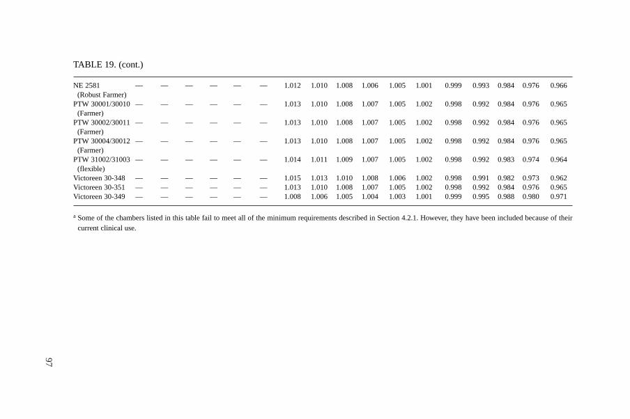
97
TABLE 19. (cont.)
NE 2581 — — — — — — 1.012 1.010 1.008 1.006 1.005 1.001 0.999 0.993 0.984 0.976 0.966(Robust Farmer)
PTW 30001/30010 — — — — — — 1.013 1.010 1.008 1.007 1.005 1.002 0.998 0.992 0.984 0.976 0.965(Farmer)
PTW 30002/30011 — — — — — — 1.013 1.010 1.008 1.007 1.005 1.002 0.998 0.992 0.984 0.976 0.965(Farmer)
PTW 30004/30012 — — — — — — 1.013 1.010 1.008 1.007 1.005 1.002 0.998 0.992 0.984 0.976 0.965(Farmer)
PTW 31002/31003 — — — — — — 1.014 1.011 1.009 1.007 1.005 1.002 0.998 0.992 0.983 0.974 0.964(flexible)
Victoreen 30-348 — — — — — — 1.015 1.013 1.010 1.008 1.006 1.002 0.998 0.991 0.982 0.973 0.962Victoreen 30-351 — — — — — — 1.013 1.010 1.008 1.007 1.005 1.002 0.998 0.992 0.984 0.976 0.965Victoreen 30-349 — — — — — — 1.008 1.006 1.005 1.004 1.003 1.001 0.999 0.995 0.988 0.980 0.971
a Some of the chambers listed in this table fail to meet all of the minimum requirements described in Section 4.2.1. However, they have been included because of theircurrent clinical use.
98
The values for k xQcross
are derived using the procedure of Section 3.2.1:
(30)
where k xQint
and k xQcross,Qint
are taken from Table 19. Note that the above may also beused for chambers calibrated at a standards laboratory at a single electron beamquality Qcross.
7.7. MEASUREMENTS UNDER NON-REFERENCE CONDITIONS
7.7.1. Central axis depth dose distributions
The measurement of a central axis depth dose distribution should follow theprocedure given in Section 7.3.2 for the measurement of R50. If an ionization chamberis used, the measured depth ionization distribution must be converted to a depth dosedistribution.32 For a beam of quality R50, this is achieved by multiplying the ioniza-tion current or charge at each measurement depth z by the stopping-power ratio sw,airat that depth. Values for sw,air are given in Table 20 as a function of R50 and the relativedepth z /R50. Linear interpolation between table entries is sufficient. These stopping-power ratios are calculated using Eq. (66) in Appendix II [91].33
Note that this procedure neglects any variation in the perturbation factor withdepth. This is a good approximation for well guarded plane-parallel chamber types.For plane-parallel chambers that are not well guarded and for cylindrical chambertypes, changes in the perturbation factor are significant and must be accounted for.Unfortunately, the existing data on perturbation factors for these chamber types havebeen verified only at depths close to the reference depth and are therefore not suitablefor use at other depths, despite their common use at these depths. The use of thesechambers to determine the depth dose distribution is therefore discouraged.
intcross
cross int
Q,QQ,Q
Q Q
xx
x,
kk =
k
32 This conversion is required in electron beams because the water to air stopping-power ratio sw,air changes rapidly with depth.
33 Values for sw,air derived from the direct use of this equation by the user must beverified by comparison with the values given in Table 20.
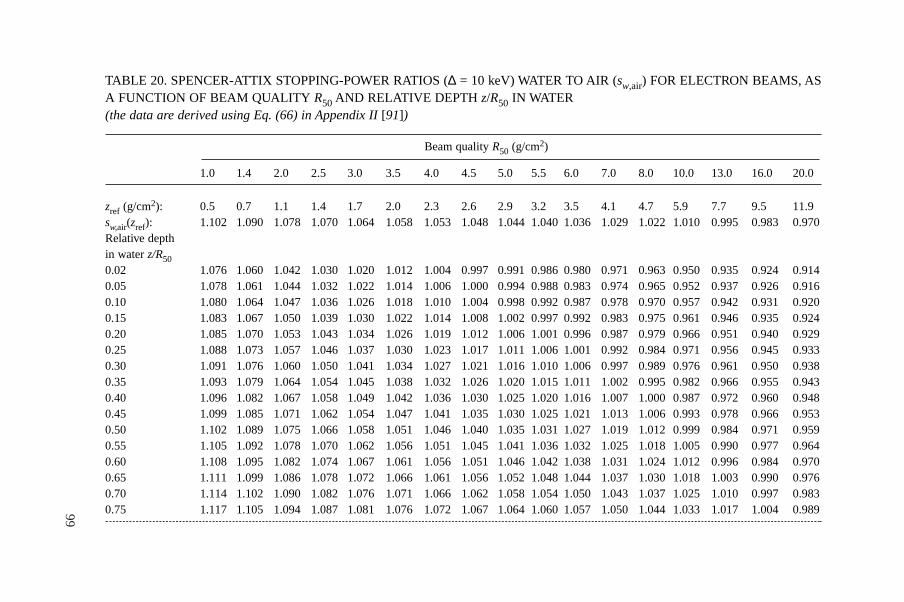
99
TABLE 20. SPENCER-ATTIX STOPPING-POWER RATIOS (∆ = 10 keV) WATER TO AIR (sw,air) FOR ELECTRON BEAMS, ASA FUNCTION OF BEAM QUALITY R50 AND RELATIVE DEPTH z/R50 IN WATER(the data are derived using Eq. (66) in Appendix II [91])
Beam quality R50 (g/cm2)
1.0 1.4 2.0 2.5 3.0 3.5 4.0 4.5 5.0 5.5 6.0 7.0 8.0 10.0 13.0 16.0 20.0
zref (g/cm2): 0.5 0.7 1.1 1.4 1.7 2.0 2.3 2.6 2.9 3.2 3.5 4.1 4.7 5.9 7.7 9.5 11.9sw,air(zref): 1.102 1.090 1.078 1.070 1.064 1.058 1.053 1.048 1.044 1.040 1.036 1.029 1.022 1.010 0.995 0.983 0.970Relative depth in water z/R500.02 1.076 1.060 1.042 1.030 1.020 1.012 1.004 0.997 0.991 0.986 0.980 0.971 0.963 0.950 0.935 0.924 0.9140.05 1.078 1.061 1.044 1.032 1.022 1.014 1.006 1.000 0.994 0.988 0.983 0.974 0.965 0.952 0.937 0.926 0.9160.10 1.080 1.064 1.047 1.036 1.026 1.018 1.010 1.004 0.998 0.992 0.987 0.978 0.970 0.957 0.942 0.931 0.9200.15 1.083 1.067 1.050 1.039 1.030 1.022 1.014 1.008 1.002 0.997 0.992 0.983 0.975 0.961 0.946 0.935 0.9240.20 1.085 1.070 1.053 1.043 1.034 1.026 1.019 1.012 1.006 1.001 0.996 0.987 0.979 0.966 0.951 0.940 0.9290.25 1.088 1.073 1.057 1.046 1.037 1.030 1.023 1.017 1.011 1.006 1.001 0.992 0.984 0.971 0.956 0.945 0.9330.30 1.091 1.076 1.060 1.050 1.041 1.034 1.027 1.021 1.016 1.010 1.006 0.997 0.989 0.976 0.961 0.950 0.9380.35 1.093 1.079 1.064 1.054 1.045 1.038 1.032 1.026 1.020 1.015 1.011 1.002 0.995 0.982 0.966 0.955 0.9430.40 1.096 1.082 1.067 1.058 1.049 1.042 1.036 1.030 1.025 1.020 1.016 1.007 1.000 0.987 0.972 0.960 0.9480.45 1.099 1.085 1.071 1.062 1.054 1.047 1.041 1.035 1.030 1.025 1.021 1.013 1.006 0.993 0.978 0.966 0.9530.50 1.102 1.089 1.075 1.066 1.058 1.051 1.046 1.040 1.035 1.031 1.027 1.019 1.012 0.999 0.984 0.971 0.9590.55 1.105 1.092 1.078 1.070 1.062 1.056 1.051 1.045 1.041 1.036 1.032 1.025 1.018 1.005 0.990 0.977 0.9640.60 1.108 1.095 1.082 1.074 1.067 1.061 1.056 1.051 1.046 1.042 1.038 1.031 1.024 1.012 0.996 0.984 0.9700.65 1.111 1.099 1.086 1.078 1.072 1.066 1.061 1.056 1.052 1.048 1.044 1.037 1.030 1.018 1.003 0.990 0.9760.70 1.114 1.102 1.090 1.082 1.076 1.071 1.066 1.062 1.058 1.054 1.050 1.043 1.037 1.025 1.010 0.997 0.9830.75 1.117 1.105 1.094 1.087 1.081 1.076 1.072 1.067 1.064 1.060 1.057 1.050 1.044 1.033 1.017 1.004 0.989
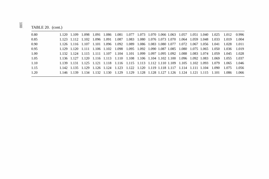
100
TABLE 20. (cont.)
0.80 1.120 1.109 1.098 1.091 1.086 1.081 1.077 1.073 1.070 1.066 1.063 1.057 1.051 1.040 1.025 1.012 0.9960.85 1.123 1.112 1.102 1.096 1.091 1.087 1.083 1.080 1.076 1.073 1.070 1.064 1.059 1.048 1.033 1.019 1.0040.90 1.126 1.116 1.107 1.101 1.096 1.092 1.089 1.086 1.083 1.080 1.077 1.072 1.067 1.056 1.041 1.028 1.0110.95 1.129 1.120 1.111 1.106 1.102 1.098 1.095 1.092 1.090 1.087 1.085 1.080 1.075 1.065 1.050 1.036 1.0191.00 1.132 1.124 1.115 1.111 1.107 1.104 1.101 1.099 1.097 1.095 1.092 1.088 1.083 1.074 1.059 1.045 1.0281.05 1.136 1.127 1.120 1.116 1.113 1.110 1.108 1.106 1.104 1.102 1.100 1.096 1.092 1.083 1.069 1.055 1.0371.10 1.139 1.131 1.125 1.121 1.118 1.116 1.115 1.113 1.112 1.110 1.109 1.105 1.102 1.093 1.079 1.065 1.0461.15 1.142 1.135 1.129 1.126 1.124 1.123 1.122 1.120 1.119 1.118 1.117 1.114 1.111 1.104 1.090 1.075 1.0561.20 1.146 1.139 1.134 1.132 1.130 1.129 1.129 1.128 1.128 1.127 1.126 1.124 1.121 1.115 1.101 1.086 1.066
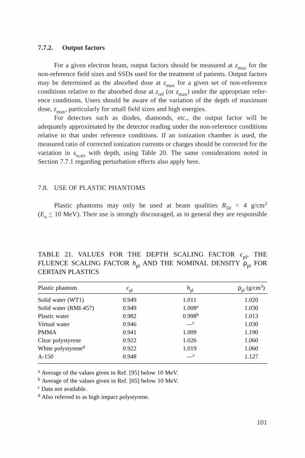
101
7.7.2. Output factors
For a given electron beam, output factors should be measured at zmax for thenon-reference field sizes and SSDs used for the treatment of patients. Output factorsmay be determined as the absorbed dose at zmax for a given set of non-referenceconditions relative to the absorbed dose at zref (or zmax) under the appropriate refer-ence conditions. Users should be aware of the variation of the depth of maximumdose, zmax, particularly for small field sizes and high energies.
For detectors such as diodes, diamonds, etc., the output factor will beadequately approximated by the detector reading under the non-reference conditionsrelative to that under reference conditions. If an ionization chamber is used, themeasured ratio of corrected ionization currents or charges should be corrected for thevariation in sw,air with depth, using Table 20. The same considerations noted inSection 7.7.1 regarding perturbation effects also apply here.
7.8. USE OF PLASTIC PHANTOMS
Plastic phantoms may only be used at beam qualities R50 < 4 g/cm2
(Eo � 10 MeV). Their use is strongly discouraged, as in general they are responsible
TABLE 21. VALUES FOR THE DEPTH SCALING FACTOR cpl, THE FLUENCE SCALING FACTOR hpl AND THE NOMINAL DENSITY ρpl FORCERTAIN PLASTICS
Plastic phantom cpl hpl ρpl (g/cm3)
Solid water (WT1) 0.949 1.011 1.020Solid water (RMI-457) 0.949 1.008a 1.030Plastic water 0.982 0.998b 1.013Virtual water 0.946 —c 1.030PMMA 0.941 1.009 1.190Clear polystyrene 0.922 1.026 1.060White polystyrened 0.922 1.019 1.060A-150 0.948 —c 1.127
a Average of the values given in Ref. [95] below 10 MeV. b Average of the values given in Ref. [65] below 10 MeV.c Data not available. d Also referred to as high impact polystyrene.
for the largest discrepancies in the determinations of absorbed dose in electron beams.Nevertheless, when accurate chamber positioning in water is not possible, or when nowaterproof chamber is available, their use is permitted. The criteria determining thechoice of plastic are discussed in Section 4.2.3.
7.8.1. Scaling of depths
Depths in plastic phantoms, zpl, expressed in g/cm2, are obtained by multiplyingthe depth in centimetres by the plastic density ρpl in g/cm3. The density of the plastic,ρpl, should be measured for the batch of plastic in use rather than using a nominalvalue for the plastic type. Measurements made in a plastic phantom at depth zpl relateto the depth in water given by
zw = zpl cpl g/cm2 (zpl in g/cm2) (31)
where cpl is a depth scaling factor. Values for cpl for certain plastics are given inTable 21 [93–95].34 Nominal values for the density ρpl for each plastic are also givenin the table. These are given only for guidance.
7.8.2. Plastic phantoms for beam quality specification
If a plastic phantom is used to measure the beam quality specifier, the measuredquantity is the half-value of the depth ionization distribution in the plastic, R50,ion,pl.The R50,ion in water is obtained using Eq. (31); that is
R50,ion = R50,ion,pl cpl g/cm2 (R50,ion,pl in g/cm2) 35 (32)
The beam quality specifier R50 in water is then obtained using Eq. (23).
102
34 In this Code of Practice, the depths zw and zpl are defined in units of g/cm2, in con-trast to their definition in centimetres in Ref. [21]. The depth scaling factor cpl is the ratio ofthe average depth of electron penetration in water and plastic [93, 94], where these depths arealso expressed in g/cm2. As a result of this change of units, and to a lesser extent the incorpo-ration of new data, the values given for cpl in Table 21 differ from those for Cpl given inTable VIII of Ref. [21]. The use of lowercase for cpl denotes the use of these factors only withdepths expressed in g/cm2.
35 Strictly, cpl factors apply only to depth dose distributions and their use in scalingdepth ionization distributions is an approximation.
7.8.3. Plastic phantoms for absorbed dose determination at zref
To determine the absorbed dose to water at zref in water using a plastic phantom,the chamber must be positioned at the scaled reference depth zref,pl in the plastic. Thisis obtained from zref in water using Eq. (31) in inverse form; that is
zref,pl = zref/cpl g/cm2 (zref in g/cm2) (33)
All other reference conditions are as in Table 17. In addition to depth scaling,the dosimeter reading MQ,pl at depth zref,pl in the plastic must be scaled to the equiv-alent reading MQ at zref in water using the relation
MQ = MQ,pl hpl (34)
Values for the fluence scaling factor hpl for certain plastics are given inTable 21.36 The uncertainty associated with this scaling is the main reason foravoiding the use of plastic phantoms. The absorbed dose to water at zref in waterfollows from the value for MQ given by Eq. (34) and the use of Eq. (25).
7.8.4. Plastic phantoms for depth dose distributions
When using a plastic phantom to determine the depth dose distribution, eachmeasurement depth in plastic must be scaled using Eq. (31) to give the appropriatedepth in water. The dosimeter reading at each depth must also be scaled usingEq. (34). For depths beyond zref,pl (as given by Eq. (33)) it is acceptable to use thevalue for hpl at zref,pl derived from Table 21. At shallower depths, this value for hplshould be decreased linearly to a value of unity at zero depth; this ignores the effectof backscatter differences at the surface.
If an ionization chamber is used, the measured depth ionization distributionmust be converted to a depth dose distribution. This is achieved by multiplying theionization current or charge at each depth by the appropriate stopping-power ratiosw,air, as described in Section 7.7.1.
103
36 In Ref. [21], values for hpl are given as a function of energy. In this Code of Practice,plastic phantoms may only be used for R50 < 4 g/cm2 (Eo � 10 MeV) and in this energy rangethe value for hpl for a given plastic can be taken as a constant to an acceptable accuracy.
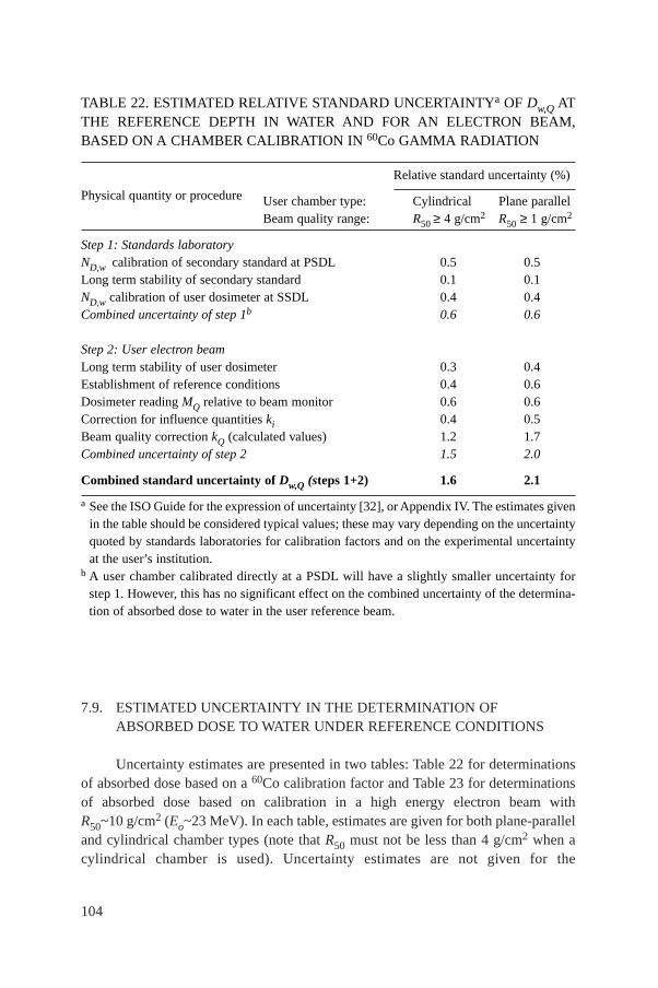
7.9. ESTIMATED UNCERTAINTY IN THE DETERMINATION OFABSORBED DOSE TO WATER UNDER REFERENCE CONDITIONS
Uncertainty estimates are presented in two tables: Table 22 for determinationsof absorbed dose based on a 60Co calibration factor and Table 23 for determinationsof absorbed dose based on calibration in a high energy electron beam withR50~10 g/cm2 (Eo~23 MeV). In each table, estimates are given for both plane-paralleland cylindrical chamber types (note that R50 must not be less than 4 g/cm2 when acylindrical chamber is used). Uncertainty estimates are not given for the
104
TABLE 22. ESTIMATED RELATIVE STANDARD UNCERTAINTYa OF Dw,Q ATTHE REFERENCE DEPTH IN WATER AND FOR AN ELECTRON BEAM,BASED ON A CHAMBER CALIBRATION IN 60Co GAMMA RADIATION
Physical quantity or procedure
Relative standard uncertainty (%)
User chamber type: Cylindrical Plane parallelBeam quality range: R50 ≥ 4 g/cm2 R50 ≥ 1 g/cm2
Step 1: Standards laboratoryND,w calibration of secondary standard at PSDL 0.5 0.5Long term stability of secondary standard 0.1 0.1ND,w calibration of user dosimeter at SSDL 0.4 0.4Combined uncertainty of step 1b 0.6 0.6
Step 2: User electron beamLong term stability of user dosimeter 0.3 0.4Establishment of reference conditions 0.4 0.6Dosimeter reading MQ relative to beam monitor 0.6 0.6Correction for influence quantities ki 0.4 0.5Beam quality correction kQ (calculated values) 1.2 1.7Combined uncertainty of step 2 1.5 2.0
Combined standard uncertainty of Dw,Q (steps 1+2) 1.6 2.1
a See the ISO Guide for the expression of uncertainty [32], or Appendix IV. The estimates givenin the table should be considered typical values; these may vary depending on the uncertaintyquoted by standards laboratories for calibration factors and on the experimental uncertaintyat the user’s institution.
b A user chamber calibrated directly at a PSDL will have a slightly smaller uncertainty forstep 1. However, this has no significant effect on the combined uncertainty of the determina-tion of absorbed dose to water in the user reference beam.
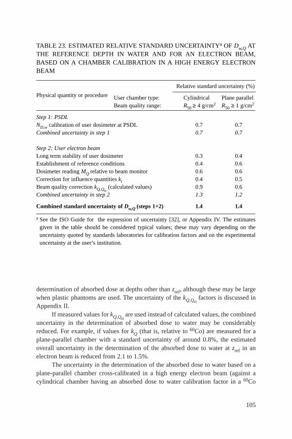
determination of absorbed dose at depths other than zref, although these may be largewhen plastic phantoms are used. The uncertainty of the kQ,Qo
factors is discussed inAppendix II.
If measured values for kQ,Qoare used instead of calculated values, the combined
uncertainty in the determination of absorbed dose to water may be considerablyreduced. For example, if values for kQ (that is, relative to 60Co) are measured for aplane-parallel chamber with a standard uncertainty of around 0.8%, the estimatedoverall uncertainty in the determination of the absorbed dose to water at zref in anelectron beam is reduced from 2.1 to 1.5%.
The uncertainty in the determination of the absorbed dose to water based on aplane-parallel chamber cross-calibrated in a high energy electron beam (against acylindrical chamber having an absorbed dose to water calibration factor in a 60Co
105
TABLE 23. ESTIMATED RELATIVE STANDARD UNCERTAINTYa OF Dw,Q ATTHE REFERENCE DEPTH IN WATER AND FOR AN ELECTRON BEAM,BASED ON A CHAMBER CALIBRATION IN A HIGH ENERGY ELECTRONBEAM
Physical quantity or procedure
Relative standard uncertainty (%)
User chamber type: Cylindrical Plane parallelBeam quality range: R50 ≥ 4 g/cm2 R50 ≥ 1 g/cm2
Step 1: PSDLND,w calibration of user dosimeter at PSDL 0.7 0.7Combined uncertainty in step 1 0.7 0.7
Step 2: User electron beamLong term stability of user dosimeter 0.3 0.4Establishment of reference conditions 0.4 0.6Dosimeter reading MQ relative to beam monitor 0.6 0.6Correction for influence quantities ki 0.4 0.5Beam quality correction kQ,Qo
(calculated values) 0.9 0.6Combined uncertainty in step 2 1.3 1.2
Combined standard uncertainty of Dw,Q (steps 1+2) 1.4 1.4
a See the ISO Guide for the expression of uncertainty [32], or Appendix IV. The estimatesgiven in the table should be considered typical values; these may vary depending on theuncertainty quoted by standards laboratories for calibration factors and on the experimentaluncertainty at the user’s institution.
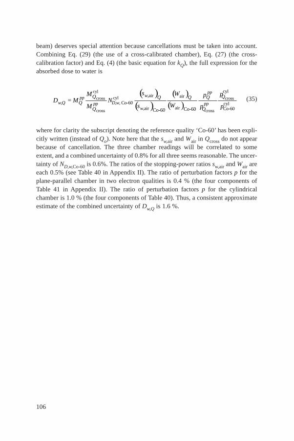
106
beam) deserves special attention because cancellations must be taken into account.Combining Eq. (29) (the use of a cross-calibrated chamber), Eq. (27) (the cross-calibration factor) and Eq. (4) (the basic equation for kQ), the full expression for theabsorbed dose to water is
(35)
where for clarity the subscript denoting the reference quality ‘Co-60’ has been expli-citly written (instead of Qo). Note here that the sw,air and Wair in Qcross do not appearbecause of cancellation. The three chamber readings will be correlated to someextent, and a combined uncertainty of 0.8% for all three seems reasonable. The uncer-tainty of ND,w,Co-60 is 0.6%. The ratios of the stopping-power ratios sw,air and Wair areeach 0.5% (see Table 40 in Appendix II). The ratio of perturbation factors p for theplane-parallel chamber in two electron qualities is 0.4 % (the four components ofTable 41 in Appendix II). The ratio of perturbation factors p for the cylindricalchamber is 1.0 % (the four components of Table 40). Thus, a consistent approximateestimate of the combined uncertainty of Dw,Q is 1.6 %.
( )( )
( )( )
cyl
cylcross cross
cross cross
cylair air
Co-60 cylairair Co-60Co-60Co-60
ppw,pp
w,Q D,w,pp ppw,
Q QQ Q QQ
Q Q
s WM ppD = M N
WsM p p

107
7.10. WORKSHEET
Determination of the absorbed dose to water in an electron beam
User: ___________________________________________________ Date: _______________
1. Radiation treatment unit and reference conditions for Dw,Q determination
Accelerator: Nominal energy: MeV
Nominal dose rate: MU/min Measured R50: g/cm2
Reference phantom: ❏ water ❏ plastic obtained from ❏ ionization ❏ dose curves
Reference field size: cm × cm Reference SSD: 100 cm
Beam quality, Q (R50,w): _______ g/cm2 Reference depth zref,w = 0.6 R50 – 0.1: g/cm2
2. Ionization chamber and electrometer
Ionization chamber model: ___________________ Serial No.: _________ Type: ❏ pp ❏ cyl
Chamber wall/window material: thickness: g/cm2
Waterproof sleeve/cover material: thickness: g/cm2
Phantom window material: thickness: g/cm2
Absorbed dose to water calibration factora ND,w,Qo= ❏ Gy/nC ❏ Gy/rdg
Calibration quality Qo: ❏ 60Co ❏ electron beam Calibration depth: g/cm2
If Qo is electron beam, give R50: g/cm2
Reference conditions for calibration Po: kPa To: °C Rel. humidity: %
Polarizing potential V1: V Calibration polarity: ❏ +ve ❏ –ve ❏ corrected for polarity
User polarity: ❏ +ve ❏ –ve effect
Calibration laboratory: Date:
Electrometer model: Serial No.:
Calibrated separately from chamber: ❏ Yes ❏ No Rating setting:
If yes, calibration laboratory: Date:
3. Phantom
Water phantom window material: thickness: g/cm2
Plastic phantom phantom material: density: g/cm3
depth scaling factor cpl: reference depth zref,pl = zref /cpl: g/cm2
fluence scaling factorb: hpl =
4. Dosimeter readingc and correction for influence quantities
Uncorrected dosimeter reading at V1 and user polarity: ❏ nC ❏ rdg
Corresponding accelerator monitor units: MU
Ratio of dosimeter reading and monitor units: M1 = ❏ nC/MU ❏ rdg/MU
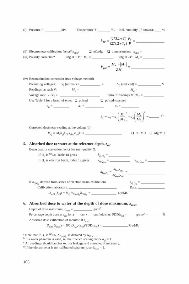
108
(i) Pressure P: _________ kPa Temperature T : _______ °C Rel. humidity (if known): ____ %
_________________
(ii) Electrometer calibration factord kelec: ❏ nC/rdg ❏ dimensionless kelec = _____________
(iii) Polarity correctione rdg at + Vl: M+ = _____________ rdg at –Vl: M– = _____________
____________________
(iv) Recombination correction (two voltage method)
Polarizing voltages: Vl (normal) = ____________ V V2 (reduced) = ______________ V
Readingsf at each V: M1 = M2 =
Voltage ratio V1/V2 = ________________________ Ratio of readings M1/M2 = ____________
Use Table 9 for a beam of type: ❏ pulsed ❏ pulsed–scanned
a0 = a1 = a2 =
______ g,h
Corrected dosimeter reading at the voltage V1:
MQ = M1hplkTPkeleckpolks = ______________________ ❏ nC/MU ❏ rdg/MU
5. Absorbed dose to water at the reference depth, zref
Beam quality correction factor for user quality Q:
If Qo is 60Co, Table 18 gives kQ,Qo=
If Qo is electron beam, Table 19 gives kQ,Qint= kQo,Qint
=
If kQ,Qoderived from series of electron beam calibrations kQ,Qo
=
Calibration laboratory: Date:
Dw,Q (zref) = MQND,w,QokQ,Qo
= Gy/MU
6. Absorbed dose to water at the depth of dose maximum, zmaxDepth of dose maximum: zmax = g/cm2
Percentage depth dose at zref for a cm × cm field size: PDD(zref = g/cm2) = %
Absorbed dose calibration of monitor at zmax:
Dw,Q (zmax) = 100 Dw,Q (zref)/PDD(zref) = Gy/MU
a Note that if Qo is 60Co, ND,w,Qois denoted by ND,w.
b If a water phantom is used, set the fluence scaling factor hpl = 1.c All readings should be checked for leakage and corrected if necessary.d If the electrometer is not calibrated separately, set kelec = 1.
int
int
Q,QQ,Qo
Q ,Qo
kk = =
k
k a aM
Ma
M
Ms = +ÊËÁ
ˆ¯̃
+ÊËÁ
ˆ¯̃
=0 11
22
1
2
2
+ –pol
M + Mk = =
2 M
kT
T
P
PTPo
o= ++
=( . )
( . )
273 2
273 2
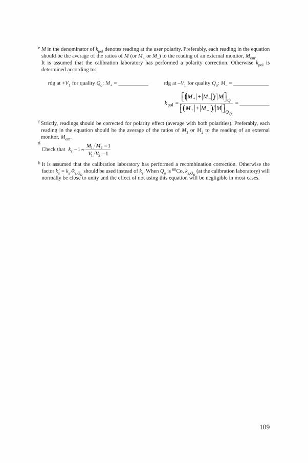
109
e M in the denominator of kpol denotes reading at the user polarity. Preferably, each reading in the equationshould be the average of the ratios of M (or M+ or M–) to the reading of an external monitor, Mem. It is assumed that the calibration laboratory has performed a polarity correction. Otherwise kpol isdetermined according to:
rdg at +V1 for quality Qo: M+ = ___________ rdg at –V1 for quality Qo: M– = _____________
___________
f Strictly, readings should be corrected for polarity effect (average with both polarities). Preferably, eachreading in the equation should be the average of the ratios of M1 or M2 to the reading of an externalmonitor, Mem.
g
Check that
h It is assumed that the calibration laboratory has performed a recombination correction. Otherwise thefactor k′s = ks /ks,Qo
should be used instead of ks. When Qo is 60Co, ks,Qo(at the calibration laboratory) will
normally be close to unity and the effect of not using this equation will be negligible in most cases.
sM M
kV V
1 2
1 2
11
1
-- ª
-
( )( )pol
+ –
+ –
Q
Q 0
M + M Mk = =
M + M M
È ˘Î ˚È ˘Î ˚
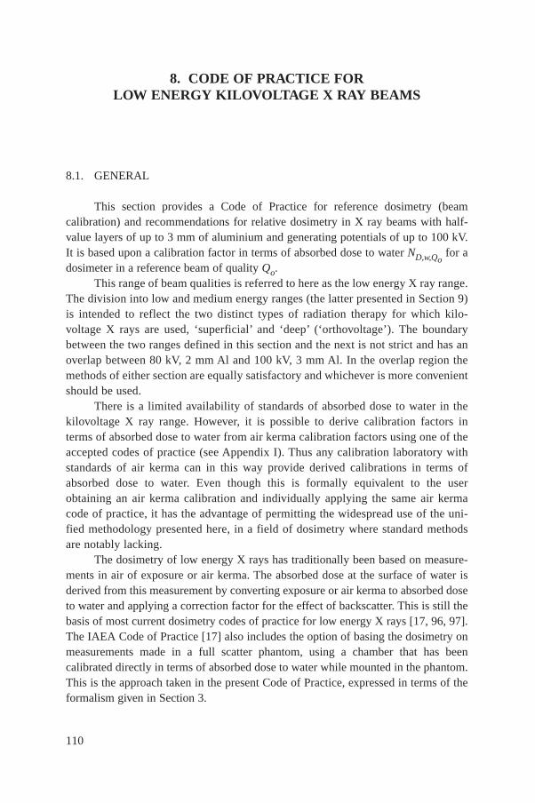
110
8. CODE OF PRACTICE FOR LOW ENERGY KILOVOLTAGE X RAY BEAMS
8.1. GENERAL
This section provides a Code of Practice for reference dosimetry (beamcalibration) and recommendations for relative dosimetry in X ray beams with half-value layers of up to 3 mm of aluminium and generating potentials of up to 100 kV.It is based upon a calibration factor in terms of absorbed dose to water ND,w,Qo
for adosimeter in a reference beam of quality Qo.
This range of beam qualities is referred to here as the low energy X ray range.The division into low and medium energy ranges (the latter presented in Section 9)is intended to reflect the two distinct types of radiation therapy for which kilo-voltage X rays are used, ‘superficial’ and ‘deep’ (‘orthovoltage’). The boundarybetween the two ranges defined in this section and the next is not strict and has anoverlap between 80 kV, 2 mm Al and 100 kV, 3 mm Al. In the overlap region themethods of either section are equally satisfactory and whichever is more convenientshould be used.
There is a limited availability of standards of absorbed dose to water in thekilovoltage X ray range. However, it is possible to derive calibration factors interms of absorbed dose to water from air kerma calibration factors using one of theaccepted codes of practice (see Appendix I). Thus any calibration laboratory withstandards of air kerma can in this way provide derived calibrations in terms ofabsorbed dose to water. Even though this is formally equivalent to the userobtaining an air kerma calibration and individually applying the same air kermacode of practice, it has the advantage of permitting the widespread use of the uni-fied methodology presented here, in a field of dosimetry where standard methodsare notably lacking.
The dosimetry of low energy X rays has traditionally been based on measure-ments in air of exposure or air kerma. The absorbed dose at the surface of water isderived from this measurement by converting exposure or air kerma to absorbed doseto water and applying a correction factor for the effect of backscatter. This is still thebasis of most current dosimetry codes of practice for low energy X rays [17, 96, 97].The IAEA Code of Practice [17] also includes the option of basing the dosimetry onmeasurements made in a full scatter phantom, using a chamber that has beencalibrated directly in terms of absorbed dose to water while mounted in the phantom.This is the approach taken in the present Code of Practice, expressed in terms of theformalism given in Section 3.
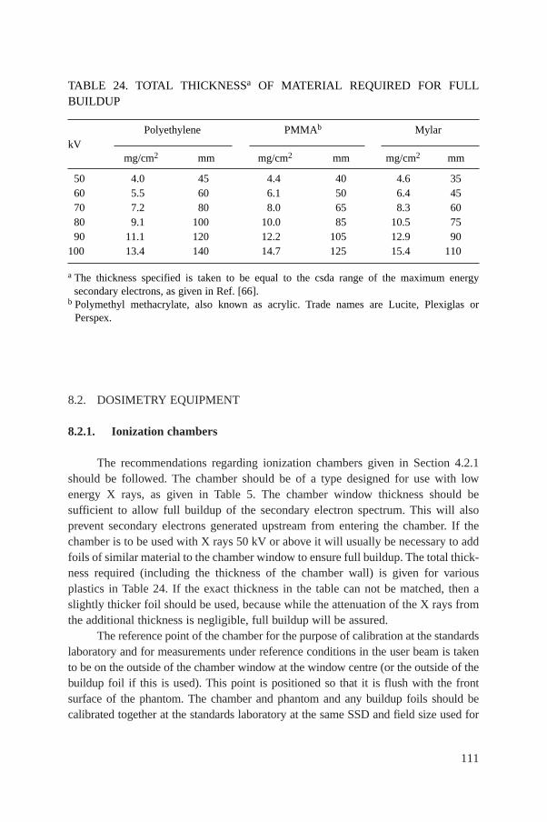
8.2. DOSIMETRY EQUIPMENT
8.2.1. Ionization chambers
The recommendations regarding ionization chambers given in Section 4.2.1should be followed. The chamber should be of a type designed for use with lowenergy X rays, as given in Table 5. The chamber window thickness should besufficient to allow full buildup of the secondary electron spectrum. This will alsoprevent secondary electrons generated upstream from entering the chamber. If thechamber is to be used with X rays 50 kV or above it will usually be necessary to addfoils of similar material to the chamber window to ensure full buildup. The total thick-ness required (including the thickness of the chamber wall) is given for variousplastics in Table 24. If the exact thickness in the table can not be matched, then aslightly thicker foil should be used, because while the attenuation of the X rays fromthe additional thickness is negligible, full buildup will be assured.
The reference point of the chamber for the purpose of calibration at the standardslaboratory and for measurements under reference conditions in the user beam is takento be on the outside of the chamber window at the window centre (or the outside of thebuildup foil if this is used). This point is positioned so that it is flush with the frontsurface of the phantom. The chamber and phantom and any buildup foils should becalibrated together at the standards laboratory at the same SSD and field size used for
111
TABLE 24. TOTAL THICKNESSa OF MATERIAL REQUIRED FOR FULLBUILDUP
kVPolyethylene PMMAb Mylar
mg/cm2 mm mg/cm2 mm mg/cm2 mm
50 4.0 45 4.4 40 4.6 3560 5.5 60 6.1 50 6.4 4570 7.2 80 8.0 65 8.3 6080 9.1 100 10.0 85 10.5 7590 11.1 120 12.2 105 12.9 90
100 13.4 140 14.7 125 15.4 110
a The thickness specified is taken to be equal to the csda range of the maximum energysecondary electrons, as given in Ref. [66].
b Polymethyl methacrylate, also known as acrylic. Trade names are Lucite, Plexiglas orPerspex.

112
reference dosimetry in the clinic. Because of large chamber to chamber variations inenergy response, it is not recommended that a generic set of kQ,Qo
values for a particulartype of chamber be used.
8.2.2. Phantoms
The recommendations regarding phantoms given in Sections 4.2.3 and 4.2.4should be followed. The phantom must permit the chamber to be mounted with theoutside face of the chamber window flush with the phantom surface. This is normallynot possible using a water phantom and so a plastic phantom should be used. The useof a water equivalent material designed for use in kilovoltage X rays is ideal butPMMA (Perspex, Lucite, etc.) is acceptable.37 Because the phantom/chamber unit iscalibrated in terms of absorbed dose to water at the surface, no dose or depth conver-sions are needed, irrespective of the type of plastic used. The phantom should extendin the beam direction by at least 5 g/cm2 and in the lateral direction at least far enoughbeyond the reference field size used to ensure that the entire primary beam exitsthrough the rear face of the phantom.
8.3. BEAM QUALITY SPECIFICATION
8.3.1. Choice of beam quality index
It has long been known that it is desirable to use more than one beam qualityparameter to characterize a kilovoltage X ray spectrum for dosimetry [98, 99]. Theusual quantities used are the kilovoltage generating potential (kV) and the half-valuelayer (HVL). However, it is often not possible to match both the kV and HVL of eachclinical beam with the beams of the standards laboratory. Therefore, the primarybeam quality index has traditionally been the HVL. This is the beam quality indexused in this Code of Practice for low energy X rays.
37 PMMA is acceptable for a phantom that is used only for measurements at the surface.This is because the phantom needs to reproduce only the backscatter, and not the attenuationor scatter at depth. The chamber is calibrated in the phantom under the reference conditions offield size and SSD, and so as long as these are similar to the reference conditions in the clinic,any difference between PMMA and water will be very small. For the measurement of outputfactors at other field sizes and SSDs, it is only the ratio of the backscatter at the differentgeometries which must be similar to that of water. Even though PMMA is not water equivalent,the backscatter is typically an order of magnitude less than the absorbed dose at the surface,and the difference in backscatter between water and PMMA is another order of magnitude lessagain. The overall disagreement is therefore typically no more than 1%.
113
In spite of the fact that previous dosimetry protocols for kV X rays have usedHVL only as the quality index, these protocols have not included any discussion onthe uncertainty arising from this choice. This is a component of uncertainty whichshould not be overlooked. Unfortunately, there is insufficient published experimentalwork to indicate how calibration factors in terms of absorbed dose to water will varyindependently with HVL and kV. Some indication may be gained from the air kermacalibration factor NK,Q for a PTW M23342 chamber over the range of typical beamsused for therapy (see Fig. 10). For a given HVL, the calibration factor varies over arange of up to a little over 2%. However, this is not truly indicative of the variation ofND,w because it does not take account of the response of the chamber to scatter fromthe phantom, or the factor to convert from air kerma to dose to water. One can onlyconjecture that the variation in ND,w,Q will be similar to that of NK,Q. A conservativefigure of 1.5% is taken as the type B standard uncertainty (see Appendix IV.3) for thetypes of chamber recommended in this Code of Practice.
It should be noted that the concept of HVL is based on the response of adosimeter to air kerma. The development of a new quality index for kV X rays basedon the quantity absorbed dose to water (possibly a ratio of doses at different depths)that can be adopted by future versions of this Code of Practice would be welcomed.
FIG. 10. Air kerma calibration factors for a PTW M23342 chamber as a function ofgenerating potential and HVL in the range 15–100 kV. Data measured at NRL.
0.05 0.1 0.5 1 51.02
1.04
1.06
1.08
1.10
1.12
NK,Q
for a PTW M23342 chamber
15 kV 30 kV 50 kV 55 kV 70 kV
100 kV
NK
,Q (
Gy/
nC1 )
HVL (mm Al)
114
It is of course preferable, where possible, to have the dosimeter calibrated at thesame combinations of kV and HVL as those of the user clinical beams. But if this isnot possible, calibration data should be obtained for beams with lesser and greaterHVLs and the desired values derived by interpolation (see the worksheet).
8.3.2. Measurement of beam quality
The conventional material used for the determination of the HVL in low energyX ray beams is aluminium. The HVL is defined as the thickness of an absorber whichreduces the air kerma rate of a narrow X ray beam at a reference point distant from theabsorbing layer to 50% compared with the air kerma rate for the non-attenuated beam.
Because of the absorption of low energy X rays in air, the HVL varies with thedistance from the X ray target. Therefore, the HVL for low energy X ray beams should,as far as possible, be measured with the chamber at the same SCD as will be used formeasurements of absorbed dose. If the distance from the target to the chamber is lessthan 50 cm, scatter from the added filters may affect the result. This can be checkedby using different field sizes and extrapolating to zero field size if necessary.
The ideal arrangement is to place at about half the distance between the X raytarget and the chamber a collimating aperture that reduces the field size to just enoughto encompass the whole of the chamber. There should be no other scattering materialin the beam up to 1 m behind the chamber. The filters added for the HVL measure-ment are placed close to the aperture in combinations of thickness which span theHVL thickness to be determined. The thickness that reduces the air kerma rate to onehalf is obtained by interpolation.
Strictly, it is the ionization current or integrated charge per exposure time thatis measured, not the air kerma rate. This distinction is particularly relevant for lightlyfiltered beams. A thin walled chamber with an energy response that varies less than2% over the quality range measured should be used.38 If required, a buildup foilshould be added to the chamber window as described in Section 8.2.1.
A monitor chamber should be used to prevent misleading results due to thevariation in X ray output. Care must be taken so that the response of the monitorchamber is not affected by increasing scatter as more filters are placed in the beam.If a monitor chamber is not available, the effects of output variation can be minimized
38 HVL measurement errors of up to 10% can result using a Farmer type chamber in alightly filtered 100 kV beam. If the chamber energy response varies by more than 2% over thequality range, then each measurement must be converted to an air kerma measurement usingan air-kerma calibration factor appropriate for each filtered or unfiltered beam. This is aniterative process because the calibration factor itself is determined by the HVL.
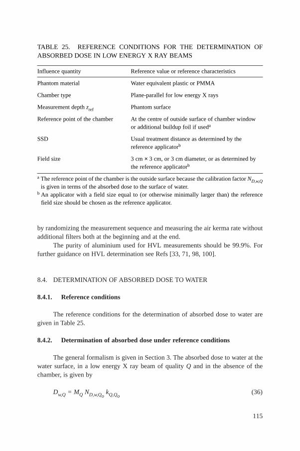
by randomizing the measurement sequence and measuring the air kerma rate withoutadditional filters both at the beginning and at the end.
The purity of aluminium used for HVL measurements should be 99.9%. Forfurther guidance on HVL determination see Refs [33, 71, 98, 100].
8.4. DETERMINATION OF ABSORBED DOSE TO WATER
8.4.1. Reference conditions
The reference conditions for the determination of absorbed dose to water aregiven in Table 25.
8.4.2. Determination of absorbed dose under reference conditions
The general formalism is given in Section 3. The absorbed dose to water at thewater surface, in a low energy X ray beam of quality Q and in the absence of thechamber, is given by
Dw,Q = MQ ND,w,QokQ,Qo
(36)
115
TABLE 25. REFERENCE CONDITIONS FOR THE DETERMINATION OFABSORBED DOSE IN LOW ENERGY X RAY BEAMS
Influence quantity Reference value or reference characteristics
Phantom material Water equivalent plastic or PMMA
Chamber type Plane-parallel for low energy X rays
Measurement depth zref Phantom surface
Reference point of the chamber At the centre of outside surface of chamber window or additional buildup foil if useda
SSD Usual treatment distance as determined by the reference applicatorb
Field size 3 cm × 3 cm, or 3 cm diameter, or as determined by the reference applicatorb
a The reference point of the chamber is the outside surface because the calibration factor ND,w,Qis given in terms of the absorbed dose to the surface of water.
b An applicator with a field size equal to (or otherwise minimally larger than) the referencefield size should be chosen as the reference applicator.
where MQ is the reading of the dosimeter with the reference point of the chamberpositioned at zref in accordance with the reference conditions given in Table 25 andcorrected for the influence quantities temperature and pressure, and electrometercalibration, as described in the worksheet (see also Section 4.4.3). Note that thepolarity and ion recombination corrections are difficult to measure on the type ofchamber recommended for low energy X rays due to electrostatic distortion of thechamber window. However, the effects will be negligible as long as the polarity iskept the same as was used for calibration and the absorbed dose rate is less than a fewgrays per second (see Ref. [101]). ND,w,Qo
is the calibration factor in terms ofabsorbed dose to water for the dosimeter at the reference quality Qo and kQ,Qo
is achamber specific factor which corrects for differences between the reference beamquality Qo and the actual beam quality being used, Q. Note also that the correctionfor timer error may be significant. It is not a multiplicative correction, and is there-fore treated separately in the worksheet.
8.5. VALUES FOR kQ,Qo
It is not possible to calculate values of kQ,Qousing Bragg–Gray theory because
a thin-walled chamber on the surface of a phantom does not represent a Bragg–Graycavity. Therefore, the values for kQ,Qo
must be obtained directly from measurements.Generic values, measured for a particular chamber type, should not be used becauseof large chamber to chamber variations in energy response.
The calibration data for the dosimeter should ideally be presented as a singlecalibration factor ND,w,Qo
determined in a reference beam of quality Qo and one ormore measured factors kQ,Qo
corresponding to the other calibration qualities, Q.However, if the calibration data are in the form of a set of calibration factors ND,w,Qthen one of the qualities should be chosen as the reference beam quality Qo.39 Thecorresponding calibration factor becomes ND,w,Qo
and the other calibration factorsND,w,Q are expressed in terms of kQ,Qo
using the relation
(37)D,w,Q
Q,QoD,w,Qo
Nk =
N
116
39 The choice here is not critical; the quality corresponding to the ND,w,Q factor with thesmallest uncertainty is appropriate, otherwise a quality close to the middle of the range.
If the quality of the user beam does not match any of the calibration qualities, thevalue for kQ,Qo
to be used in Eq. (36) can be interpolated (see worksheet).A chamber calibrated in a series of beam qualities may be subsequently recali-
brated at only the reference quality Qo. In this case the new value for ND,w,Qoshould
be used with the values of kQ,Qopreviously measured. However, because of the
particular susceptibility of ionization chambers to change in energy response to lowenergy X rays, it is preferable that chambers are recalibrated at all qualities each time.In particular, if ND,w,Qo
changes by an amount more than the uncertainty stated for thecalibration, or there have been any repairs to the chamber, then the dosimeter shouldbe re-calibrated at all qualities.
8.6. MEASUREMENTS UNDER NON-REFERENCE CONDITIONS
8.6.1. Central axis depth dose distributions
An estimate of depth dose distributions may be obtained from the literature[81]. However if desired, the depth dose distribution can be measured by using thesame chamber as that used for reference dosimetry and a water equivalent phantom.
Thin sheets of water equivalent phantom material designed for use with kilo-voltage X rays are placed over the chamber in its phantom and the phantom is movedback by the same amount to maintain a constant SSD. The manufacturer’s specificationsfor the material should state that it is equivalent to water within a few per cent in theenergy range of interest. This should be verified by comparison with published data.PMMA is not suitable for measurement of depth dose distributions, even if it is used asthe phantom material for reference dosimetry. Strictly, this procedure provides a depthionization distribution rather than the depth dose distribution. However, if the responseof the chamber is reasonably constant (within 5%) with beam quality, the error intro-duced by assuming that the depth dose distribution is the same as the depth ionizationdistribution is not likely to be more than a few per cent at any clinically relevant depth.
8.6.2. Output factors
For clinical applications, output factors are required for all combinations of SSDand field size used for radiotherapy treatments. The output factor is the ratio of the cor-rected dosimeter reading at the surface for a given set of non-reference conditions tothat for the reference conditions (reference conditions are given in Table 25).
Because of the significant scatter contribution from the inside of an applicator,it is not sufficiently accurate to estimate output factors for different applicators usingthe ratio of the backscatter factors corresponding to the respective field sizes. Theoutput factor must be measured for each beam quality and each individual applicator.
117
If a PMMA phantom is used, the response of the chamber to different field sizeswill not be exactly the same as that for a water phantom, owing to the difference inbackscatter (see footnote 37). However, because the output factor is a ratio ofmeasurements, this effect should not incur an error of greater than 1%, particularly ifthe reference field size is in the middle of the range of sizes used clinically.
8.7. ESTIMATED UNCERTAINTY IN THE DETERMINATION OFABSORBED DOSE TO WATER UNDER REFERENCE CONDITIONS
There is to date very little practical experience in primary standards of absorbeddose for low energy X rays. The uncertainty in ND,w,Q determined directly from aprimary standard is assumed here to be 1%. Alternatively, if the calibration factor interms of absorbed dose to water is derived from a standard of air kerma, the uncer-tainty in the determination of ND,w,Q is estimated as 3%. In the latter case, the uncer-tainty of ND,w,Q then dominates the overall uncertainty.
The stability of a good dosimeter over a series of readings is typically betterthan 0.1%, but the temperature of the chamber may be uncertain to at least ±1°Cbecause of heating from the X ray tube. The X ray output from some machinesdepends on line voltage, tube temperature, and operator control of tube current andvoltage. This variation is minimized when the exposures are controlled by a monitorchamber, but this is rarely the case on dedicated low energy X ray machines wherethe variation in output over a series of identical exposure times may be as much as5%. This uncertainty should be separately estimated by the user from the standarddeviation of a set of at least five exposures of typical treatment length. It is notincluded in this analysis.
Because the SSD is often very short on a low energy X ray machine, there maybe difficulty in achieving a positioning reproducibility that results in an uncertainty inthe determination of absorbed dose to water better than 1%, so this uncertainty isassigned to establishment of reference conditions.
For low energy X ray dosimetry, the values for kQ,Qoare derived directly from
the calibration factors ND,w,Q. If the value of ND,w,Qoused in Eq. (36) is the same as
that used in Eq. (37), then the uncertainty in the product kQ,QoND,w,Qo
is just theuncertainty in ND,w,Q together with an additional 1.5% to account for the uncertaintyof matching the calibration and user beams on the basis of HVL. However, if theND,w,Qo
used in Eq. (36) is different because it has been obtained from a subsequentcalibration of the dosimeter, then the uncertainty in kQ,Qo
is increased because of thelack of correlation between the new ND,w,Qo
and that used to calculate the kQ,Qo. This
results in an increase in the combined standard uncertainty of Dw,Q of about 0.2%.The uncertainties are summarized in Table 26.
118
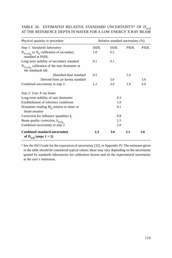
119
TABLE 26. ESTIMATED RELATIVE STANDARD UNCERTAINTYa OF Dw,QAT THE REFERENCE DEPTH IN WATER FOR A LOW ENERGY X RAY BEAM
Physical quantity or procedure Relative standard uncertainty (%)
Step 1: Standards laboratory SSDL SSDL PSDL PSDLND,w,Qo
or NK calibration of secondary 1.0 0.5standard at PSDL
Long term stability of secondary standard 0.1 0.1ND,w,Qo
calibration of the user dosimeter at the standards lab
Absorbed dose standard 0.5 1.0Derived from air kerma standard 3.0 3.0
Combined uncertainty in step 1: 1.2 3.0 1.0 3.0
Step 2: User X ray beamLong term stability of user dosimeter 0.3Establishment of reference conditions 1.0Dosimeter reading MQ relative to timer or 0.1
beam monitorCorrection for influence quantities ki 0.8Beam quality correction, kQ,Qo
1.5Combined uncertainty in step 2 2.0
Combined standard uncertainty 2.3 3.6 2.2 3.6of Dw,Q (steps 1 + 2)
a See the ISO Guide for the expression of uncertainty [32], or Appendix IV. The estimates givenin the table should be considered typical values; these may vary depending on the uncertaintyquoted by standards laboratories for calibration factors and on the experimental uncertaintyat the user’s institution.
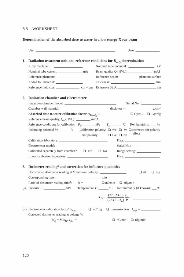
120
8.8. WORKSHEET
Determination of the absorbed dose to water in a low energy X ray beam
User: Date:
1. Radiation treatment unit and reference conditions for Dw,Q determination
X ray machine: Nominal tube potential: kV
Nominal tube current: mA Beam quality Q (HVL): mAl
Reference phantom: Reference depth: phantom surface
Added foil material: Thickness: mm
Reference field size: cm × cm Reference SSD: cm
2. Ionization chamber and electrometer
Ionization chamber model: Serial No.:
Chamber wall material: thickness = g/cm2
Absorbed dose to water calibration factor ND,w,Qo = ❏ Gy/nC ❏ Gy/rdg
Reference beam quality, Qo (HVL): mmAl
Reference conditions for calibration Po: kPa To: °C Rel. humidity: %
Polarizing potential V: V Calibration polarity: ❏ +ve ❏ –ve ❏ corrected for polarity
User polarity: ❏ +ve ❏ –ve effect
Calibration laboratory: Date:
Electrometer model: Serial No.:
Calibrated separately from chamber? ❏ Yes ❏ No Range setting:
If yes, calibration laboratory: Date:
3. Dosimeter readinga and correction for influence quantities
Uncorrected dosimeter reading at V and user polarity: ❏ nC ❏ rdg
Corresponding time: min
Ratio of dosimeter reading timeb: M = ❏ nC/min ❏ rdg/min
(i) Pressure P: _____________ kPa Temperature T : ______ °C Rel. humidity (if known): ___ %
_________________
(ii) Electrometer calibration factorc kelec: ❏ nC/rdg ❏ dimensionless kelec = ____________
Corrected dosimeter reading at voltage V:
MQ = M kTP kelec = ❏ nC/min ❏ rdg/min
kT
T
P
PTPo
o= ++
=( . )
( . )
273 2
273 2
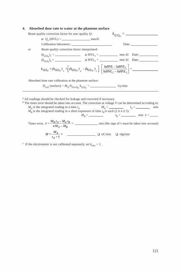
121
4. Absorbed dose rate to water at the phantom surface
Beam quality correction factor for user quality Q: kQ,Qo=
at Qo (HVL) = mmAl
Calibration laboratory: Date:
or Beam quality correction factor interpolated:
(kQ,Qo)1 = at HVL1 = mm Al Date:
(kQ,Qo)2 = at HVL2 = mm Al Date:
________________
Absorbed dose rate calibration at the phantom surface:
Dw,Q (surface) = MQ ND,w,QokQ,Qo
= Gy/min
a All readings should be checked for leakage and corrected if necessary.b The timer error should be taken into account. The correction at voltage V can be determined according to:
MA is the integrated reading in a time tA MA = _________ tA = ________ minMB is the integrated reading in n short exposures of time tB/n each (2 ≤ n ≤ 5)
MB = _________ tB = _________ min n =
Timer error, min (the sign of τ must be taken into account)
❏ nC/min ❏ rdg/min
c If the electrometer is not calibrated separately, set kelec = 1.
A
A
MM = =
t +t
B A A B
A B
M t – M t= =
n M – Mt
1 2 1
1
1
ln ln
ln ln2Q,Q Q,Q Q,Q Q,Qo o o o
HVL – HVLk =(k ) + (k ) – (k ) =
HVL – HVL
È ˘È ˘ Í ˙Í ˙Î ˚ Î ˚
9. CODE OF PRACTICE FOR MEDIUM ENERGYKILOVOLTAGE X RAY BEAMS
9.1. GENERAL
This section provides a Code of Practice for reference dosimetry (beamcalibration) and recommendations for relative dosimetry in X ray beams with half-value layers (HVL) greater than 2 mm of aluminium and generating potentials higherthan 80 kV. It is based upon a calibration factor in terms of absorbed dose to waterND,w,Qo
for a dosimeter in a reference beam of quality Qo.This range of beam qualities is referred to here as the medium energy X ray
range. The division into low and medium energy ranges (the former presented inSection 8) is intended to reflect the two distinct types of radiation therapy for whichkilovoltage X rays are used, ‘superficial’ and ‘deep’ (‘orthovoltage’). The boundarybetween the two ranges defined in this and the previous section is not strict and hasan overlap between 80 kV, 2 mm Al and 100 kV, 3 mm Al. In the overlap region themethods of either section are equally satisfactory and whichever is more convenientshould be used.
There is a limited availability of standards of absorbed dose to water in thekilovoltage X ray range. However, it is possible to derive calibration factors in termsof absorbed dose to water from air kerma calibration factors using one of theaccepted codes of practice (see Appendix II). Thus any calibration laboratory withstandards of air kerma can in this way provide derived calibration factors in terms ofabsorbed dose to water. Even though this is formally equivalent to the user obtainingan air kerma calibration and individually applying the same air kerma code ofpractice, it has the advantage of permitting the widespread use of the unifiedmethodology presented here, in a field of dosimetry where standard methods arenotably lacking.
Most codes of practice for the dosimetry of kilovoltage X rays specify that,for at least part of the energy range, dosimetry is based on the measurement of air kerma free in air. The absorbed dose at the surface of a water phantom is thenderived by converting air kerma to absorbed dose to water and by the use of MonteCarlo calculated backscatter factors [17,96,97]. In this Code of Practice,because absorbed dose is measured directly, all measurements are done in a waterphantom.
Medium energy X rays are used today to deliver a therapeutic dose in the depthrange of a few millimetres to a few centimetres in tissue. This is in contrast to theearly use of this modality of radiation therapy, when treatments were often muchdeeper. Consequently, the traditional reference depth for measurement of 5 g/cm2 inwater is reduced in this Code of Practice to 2 g/cm2.
122
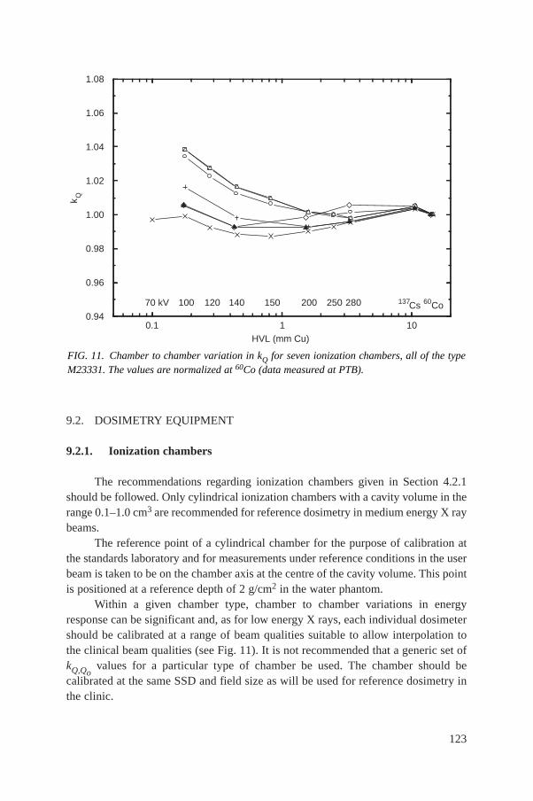
9.2. DOSIMETRY EQUIPMENT
9.2.1. Ionization chambers
The recommendations regarding ionization chambers given in Section 4.2.1should be followed. Only cylindrical ionization chambers with a cavity volume in therange 0.1–1.0 cm3 are recommended for reference dosimetry in medium energy X raybeams.
The reference point of a cylindrical chamber for the purpose of calibration atthe standards laboratory and for measurements under reference conditions in the userbeam is taken to be on the chamber axis at the centre of the cavity volume. This pointis positioned at a reference depth of 2 g/cm2 in the water phantom.
Within a given chamber type, chamber to chamber variations in energyresponse can be significant and, as for low energy X rays, each individual dosimetershould be calibrated at a range of beam qualities suitable to allow interpolation tothe clinical beam qualities (see Fig. 11). It is not recommended that a generic set ofkQ,Qo
values for a particular type of chamber be used. The chamber should becalibrated at the same SSD and field size as will be used for reference dosimetry inthe clinic.
123
0.1 1 100.94
0.96
0.98
1.00
1.02
1.04
1.06
1.08
70 kV 137Cs280250200150140120100 60Co
k Q
HVL (mm Cu)
FIG. 11. Chamber to chamber variation in kQ for seven ionization chambers, all of the typeM23331. The values are normalized at 60Co (data measured at PTB).
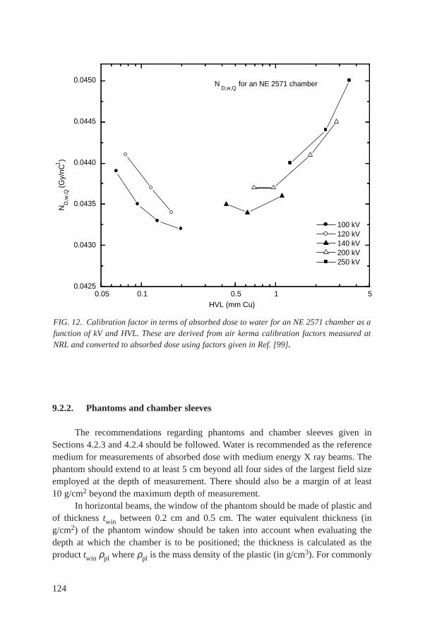
9.2.2. Phantoms and chamber sleeves
The recommendations regarding phantoms and chamber sleeves given inSections 4.2.3 and 4.2.4 should be followed. Water is recommended as the referencemedium for measurements of absorbed dose with medium energy X ray beams. Thephantom should extend to at least 5 cm beyond all four sides of the largest field sizeemployed at the depth of measurement. There should also be a margin of at least10 g/cm2 beyond the maximum depth of measurement.
In horizontal beams, the window of the phantom should be made of plastic andof thickness twin between 0.2 cm and 0.5 cm. The water equivalent thickness (ing/cm2) of the phantom window should be taken into account when evaluating thedepth at which the chamber is to be positioned; the thickness is calculated as theproduct twin ρpl where ρpl is the mass density of the plastic (in g/cm3). For commonly
124
FIG. 12. Calibration factor in terms of absorbed dose to water for an NE 2571 chamber as afunction of kV and HVL. These are derived from air kerma calibration factors measured atNRL and converted to absorbed dose using factors given in Ref. [99].
0.05 0.1 0.5 1 5
ND
,w,Q
(G
y/nC
1)
HVL (mm Cu)
0.0425
0.0430
0.0435
0.0440
0.0445
0.0450 ND,w,Q
for an NE 2571 chamber
100 kV 120 kV 140 kV 200 kV 250 kV
used plastics PMMA and clear polystyrene, the nominal values ρPMMA = 1.19 g/cm3
and ρpolystyrene = 1.06 g/cm3 [64] may be used for the calculation of the water equiv-alent thickness of the window.
For non-waterproof chambers a waterproofing sleeve should be used, made ofPMMA, and preferably not thicker than 1.0 mm. The air gap between the chamberwall and the waterproofing sleeve should be sufficient (0.1–0.3 mm) to allow the airpressure in the chamber to equilibrate. The same waterproofing sleeve that was usedfor calibration of the user’s ionization chamber should also be used for referencedosimetry. If it is not possible to use the same waterproofing sleeve that was usedduring calibration at the standardizing laboratory, then another sleeve of the samematerial and of similar thickness should be used.
9.3. BEAM QUALITY SPECIFICATION
9.3.1. Choice of beam quality index
It has long been known that it is desirable to use more than one beam qualityparameter to characterize a kilovoltage X ray spectrum for dosimetry [98, 99]. Theusual quantities used are the kilovoltage generating potential (kV) and the HVL.However, it is often not possible to match both the kV and HVL of each clinical beamwith the beams of the standards laboratory. Therefore the primary beam quality indexhas traditionally been the HVL, and this is the beam quality index used in this Codeof Practice.40
Up until now there are insufficient experimental data available to know howND,w,Qo
for a medium energy X ray chamber varies independently with HVL andgenerating potential. However, some indication can be gained from Fig. 12 whichshows a plot of ND,w,Q for an NE 2571 chamber as a function of HVL and kV for arange of typical therapy beam qualities. These values have been obtained from NK,Q(air kerma calibration factor) data using conversion factors given by Seuntjens [99].
125
40 Other beam quality specifiers were proposed by the ICRU in Refs [98, 99], includinga two point specification in terms of the so called ‘fall-off’ ratio. A recent proposal for usingthe ratio of absorbed doses at 2 cm and 5 cm depths in water [102] is promising but needs fur-ther investigation. This ratio is likely to be related to the mean X ray energy at the measure-ment depth in the phantom, which is potentially a better beam quality specifier than the HVL,which is measured in air. As noted in Section 8, the HVL is based on air kerma measurementsand requires a knowledge of the response of the dosimeter to air kerma. The development of anew quality index for kV X rays based on the quantity absorbed dose to water, that is moreappropriate for this Code of Practice, would be welcomed.
126
The data suggest that the variation in ND,w,Q arising from using HVL only as the beamquality index could be of the order of 1%. A conservative figure of 1.0% is thereforetaken as the resulting Type B standard uncertainty (see Appendix IV.3).
It is of course preferable, where possible, to have the dosimeter calibrated at thesame combinations of kV and HVL as those of the user clinical beams. But, if this isnot possible, calibration data should be obtained for beams with lesser and greaterHVLs and the desired values derived by interpolation (see worksheet).
9.3.2. Measurement of beam quality
In medium energy X ray beams, both aluminium and copper are used to deter-mine the HVL. The HVL is defined as the thickness of an absorber which reduces theair kerma rate of a narrow X ray beam at a reference point distant from the absorbinglayer to 50% compared with the air kerma rate for a non-attenuated beam.
The ideal arrangement is to place at about half the distance between the X raytarget and the chamber a collimating aperture that reduces the field size to just enoughto encompass the whole of the chamber. There should be no other scattering materialin the beam up to 1 m behind the chamber. The filters added for the HVL measure-ment are placed close to the aperture in combinations of thickness which span theHVL thickness to be determined. The thickness that reduces the air kerma rate to onehalf is obtained by interpolation.
Strictly, it is the ionization current or the integrated charge per exposure timethat is measured, not the air kerma rate. This distinction is particularly relevant forlightly filtered beams. A chamber with an energy response that varies less than 2%over the quality range measured should be used.41
A monitor chamber should be used to prevent misleading results due to thevariation in X ray output. Care must be taken so that the response of the monitorchamber is not affected by increasing scatter as more filters are placed in the path ofthe beam. If a monitor chamber is not available, the effects of output variation can beminimized by randomizing the measurement sequence and measuring the air kermarate without additional filters both at the beginning and at the end.
The purity of aluminium or copper used for HVL measurements should be99.9%. For further guidance on HVL determination see Refs [33, 71, 98, 100].
41 HVL measurement errors of up to 10% can result using a Farmer type chamber in alightly filtered 100 kV beam. If the chamber energy response varies by more than 2% over thequality range, then each measurement must be converted to an air kerma measurement usingan air kerma calibration factor appropriate for each filtered or unfiltered beam. This is an iter-ative process because the calibration factor itself is determined by the HVL.
9.4. DETERMINATION OF ABSORBED DOSE TO WATER
9.4.1. Reference conditions
The reference conditions for the determination of absorbed dose to water aregiven in Table 27.
9.4.2. Determination of absorbed dose under reference conditions
The general formalism is given in Section 3. The absorbed dose to water at thereference depth zref in water, in a medium energy X ray beam of quality Q and in theabsence of the chamber, is given by
Dw,Q = MQ ND,w,QokQ,Qo
(38)
where MQ is the reading of the dosimeter with the reference point of the chamberpositioned at zref in accordance with the reference conditions given in Table 27 andcorrected for the influence quantities temperature and pressure, polarity, andelectrometer calibration, as described in the worksheet (see also Section 4.4.3). Thecorrection for polarity is likely to be negligible. However, it should be checked at leastonce, and there is provision for this in the worksheet. Alternatively, if the samepolarity that was used for calibration is always used for clinical measurements theeffect will cancel. The ionic recombination is negligible when the absorbed dose rateis less than a few grays per minute (see Ref. [101]). ND,w,Qo
is the calibration factorin terms of absorbed dose to water for the dosimeter at the reference quality Qo, andkQ,Qo
is a chamber specific factor which corrects for differences between thereference beam quality Qo and the actual beam quality being used, Q. Note also thatthe correction for timer error may be significant. It is not a multiplicative correction,and is therefore treated separately in the worksheet.
9.5. VALUES FOR kQ,Qo
The Bragg–Gray theory cannot be applied to ionization chambers in mediumenergy X rays [103] and therefore the values for kQ,Qo
must be obtained directly frommeasurements. Generic values, measured for a particular chamber type, should not beused because of large chamber to chamber variations in kQ,Qo
with HVL (see Fig. 11).The calibration data for the dosimeter should ideally be presented as a single
calibration factor ND,w,Qodetermined in a reference beam of quality Qo and one or
more measured factors kQ,Qocorresponding to the other calibration qualities Q.
However, if the calibration data are in the form of a set of calibration factors ND,w,Q
127
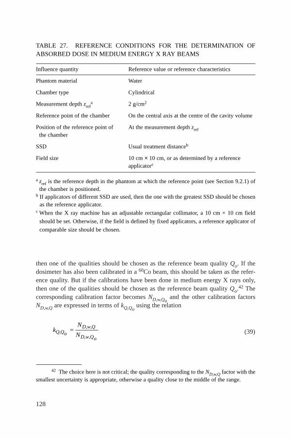
128
then one of the qualities should be chosen as the reference beam quality Qo. If thedosimeter has also been calibrated in a 60Co beam, this should be taken as the refer-ence quality. But if the calibrations have been done in medium energy X rays only,then one of the qualities should be chosen as the reference beam quality Qo.42 Thecorresponding calibration factor becomes ND,w,Qo
and the other calibration factorsND,w,Q are expressed in terms of kQ,Qo
using the relation
(39)D,w,Q
Q,QoD,w,Qo
Nk =
N
42 The choice here is not critical; the quality corresponding to the ND,w,Q factor with thesmallest uncertainty is appropriate, otherwise a quality close to the middle of the range.
TABLE 27. REFERENCE CONDITIONS FOR THE DETERMINATION OFABSORBED DOSE IN MEDIUM ENERGY X RAY BEAMS
Influence quantity Reference value or reference characteristics
Phantom material Water
Chamber type Cylindrical
Measurement depth zrefa 2 g/cm2
Reference point of the chamber On the central axis at the centre of the cavity volume
Position of the reference point of At the measurement depth zrefthe chamber
SSD Usual treatment distanceb
Field size 10 cm × 10 cm, or as determined by a reference applicatorc
a zref is the reference depth in the phantom at which the reference point (see Section 9.2.1) ofthe chamber is positioned.
b If applicators of different SSD are used, then the one with the greatest SSD should be chosenas the reference applicator.
c When the X ray machine has an adjustable rectangular collimator, a 10 cm × 10 cm field
should be set. Otherwise, if the field is defined by fixed applicators, a reference applicator of
comparable size should be chosen.
129
If the quality of the user beam does not match any of the calibration qualities, thevalue for kQ,Qo
to be used in Eq. (38) can be interpolated (see worksheet).A chamber calibrated in a series of beam qualities may be subsequently recali-
brated at only the reference quality Qo. In this case, the new value for ND,w,Qoshould
be used with the values of kQ,Qopreviously measured. However, because of the
particular susceptibility of ionization chambers to change in energy response tomedium energy X rays, it is preferable that chambers are recalibrated at all qualitieseach time. In particular, if ND,w,Qo
changes by an amount more than the uncertaintystated for the calibration, or there have been any repairs to the chamber, then thedosimeter should be recalibrated at all qualities.
9.6. MEASUREMENTS UNDER NON-REFERENCE CONDITIONS
9.6.1. Central axis depth dose distributions
A measurement under reference conditions prescribed in this Code of Practiceprovides absorbed dose at the depth of 2 g/cm2 in water. In order to relate thismeasurement to the dose at other depths it is usually necessary to obtain the centralaxis depth dose distribution. An estimate of the depth dose distribution may beobtained from the literature [81]. However, it is unlikely that the published data willmatch the exact kV and HVL of the clinical beam. Therefore, it is recommended thatthe depth dose distributions be measured for each clinical beam.
In spite of kilovoltage X rays having been used in radiotherapy for somedecades, the methods of relative dosimetry have not been extensively researched.According to Seuntjens and Verhaegan [104], a Farmer type cylindrical chamberthat is suitable for reference dosimetry should have a response in a phantom whichis reasonably independent of depth and field size. However, a chamber of this typecannot be reliably used at depths in a phantom of less than about 0.5 cm. Dependingon the field size and beam energy, there may be a significant variation in theabsorbed dose in the first few millimetres of the depth dose distribution (seeFig. 13).
It is possible to measure the depth dose distribution using a small ionizationchamber in a scanning tank, as used for relative dosimetry in high energy electron andphoton beams, or using a plane-parallel chamber of the type used for high energyelectron dosimetry [105]. This has the advantage of allowing measurements at depthsof less than 0.5 cm. However, these chamber types are not designed for use with kVX rays and so the relationship between the depth ionization distribution and the depthdose distribution (at depths greater than 0.5 cm) must be determined by comparisonwith a Farmer type cylindrical chamber at a number of suitable depths. (The depth ofmeasurement of a cylindrical chamber in a phantom is taken to be the depth of the
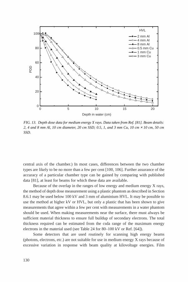
130
central axis of the chamber.) In most cases, differences between the two chambertypes are likely to be no more than a few per cent [100, 106]. Further assurance of theaccuracy of a particular chamber type can be gained by comparing with publisheddata [81], at least for beams for which these data are available.
Because of the overlap in the ranges of low energy and medium energy X rays,the method of depth dose measurement using a plastic phantom as described in Section8.6.1 may be used below 100 kV and 3 mm of aluminium HVL. It may be possible touse the method at higher kV or HVL, but only a plastic that has been shown to givemeasurements that agree within a few per cent with measurements in a water phantomshould be used. When making measurements near the surface, there must always besufficient material thickness to ensure full buildup of secondary electrons. The totalthickness required can be estimated from the csda range of the maximum energyelectrons in the material used (see Table 24 for 80–100 kV or Ref. [64]).
Some detectors that are used routinely for scanning high energy beams(photons, electrons, etc.) are not suitable for use in medium energy X rays because ofexcessive variation in response with beam quality at kilovoltage energies. Film
FIG. 13. Depth dose data for medium energy X rays. Data taken from Ref. [81]. Beam details:2, 4 and 8 mm Al, 10 cm diameter, 20 cm SSD; 0.5, 1, and 3 mm Cu, 10 cm × 10 cm, 50 cmSSD.
0 5 10 15 200
20
40
60
80
100HVL
2 mm Al 4 mm Al 8 mm Al 0.5 mm Cu 1 mm Cu 3 mm Cu
PD
D
Depth in water (cm)
131
dosimetry and semiconductor diodes are, for this reason, not suitable. Some TLDmaterials are suitable, but the energy response must be checked against an ionizationchamber before use.
9.6.2. Output factors
For clinical applications, output factors are required for all combinations ofSSD and field size used for radiotherapy treatment. The output factor for mediumenergy X rays is the ratio of the absorbed dose at the surface of a water phantom fora given SSD and field size to the absorbed dose measured under reference conditions(reference conditions are given in Table 27). It is generally not possible to make reli-able measurements directly at the surface of a phantom since there must be sufficientdepth to provide full buildup of secondary electrons. The method recommended inthis Code of Practice to obtain the output factor for each combination of SSD andfield size is to measure the absorbed dose to water at the depth of 2 g/cm2 relative tothe absorbed dose measured under reference conditions for that beam quality, andthen to obtain the absorbed dose at the surface by extrapolation using a depth dosedistribution measured as described in Section 9.6.1.
9.7. ESTIMATED UNCERTAINTY IN THE DETERMINATION OFABSORBED DOSE TO WATER UNDER REFERENCE CONDITIONS
There is to date very little practical experience in standards of absorbed dose formedium energy X rays. The uncertainty in ND,w,Qo
determined directly from a primarystandard is taken here to be 1%. Alternatively, if the absorbed dose to water is derivedfrom a standard of air kerma, the uncertainty in the determination of ND,w,Q isestimated as 3%. In the latter case, the uncertainty of ND,w,Qo
then dominates theoverall uncertainty.
The X ray output from some machines depends on line voltage, tube tempera-ture and operator control of tube current and voltage. This uncertainty should beseparately estimated by the user from the standard deviation of a set of at least fiveexposures of typical treatment length. It is not included in this analysis.
Because the dose gradient from beams at the lower end of the energy range maybe as large as 1% per millimetre, there may be difficulty in achieving a depthpositioning reproducibility of better than 1%, so this uncertainty is assigned to theestablishment of reference conditions.
For medium energy X ray dosimetry, the values for kQ,Qoare derived directly
from the calibration factors ND,w,Q. If the value of ND,w,Qoused in Eq. (38) is the
same as that used in Eq. (39), then the uncertainty in the product kQ,QoND,w,Qo
isjust the uncertainty in ND,w,Q together with an additional 1.0% to account for the
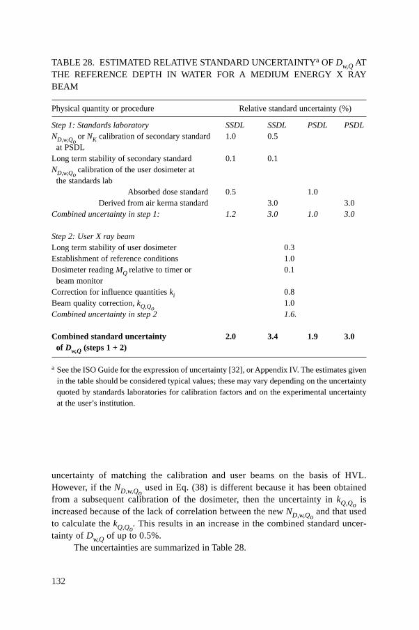
132
uncertainty of matching the calibration and user beams on the basis of HVL.However, if the ND,w,Qo
used in Eq. (38) is different because it has been obtainedfrom a subsequent calibration of the dosimeter, then the uncertainty in kQ,Qo
isincreased because of the lack of correlation between the new ND,w,Qo
and that usedto calculate the kQ,Qo
. This results in an increase in the combined standard uncer-tainty of Dw,Q of up to 0.5%.
The uncertainties are summarized in Table 28.
TABLE 28. ESTIMATED RELATIVE STANDARD UNCERTAINTYa OF Dw,Q ATTHE REFERENCE DEPTH IN WATER FOR A MEDIUM ENERGY X RAYBEAM
Physical quantity or procedure Relative standard uncertainty (%)
Step 1: Standards laboratory SSDL SSDL PSDL PSDLND,w,Qo
or NK calibration of secondary standard 1.0 0.5at PSDL
Long term stability of secondary standard 0.1 0.1ND,w,Qo
calibration of the user dosimeter at the standards lab
Absorbed dose standard 0.5 1.0Derived from air kerma standard 3.0 3.0
Combined uncertainty in step 1: 1.2 3.0 1.0 3.0
Step 2: User X ray beamLong term stability of user dosimeter 0.3Establishment of reference conditions 1.0Dosimeter reading MQ relative to timer or 0.1
beam monitorCorrection for influence quantities ki 0.8Beam quality correction, kQ,Qo
1.0Combined uncertainty in step 2 1.6.
Combined standard uncertainty 2.0 3.4 1.9 3.0of Dw,Q (steps 1 + 2)
a See the ISO Guide for the expression of uncertainty [32], or Appendix IV. The estimates givenin the table should be considered typical values; these may vary depending on the uncertaintyquoted by standards laboratories for calibration factors and on the experimental uncertaintyat the user’s institution.

133
9.8. WORKSHEET
Determination of the absorbed dose to water in a medium energy X ray beam
User: Date:
1. Radiation treatment unit and reference conditions for Dw,Q determination
X ray machine: Nominal tube potential: kV
Nominal tube current: mA Beam quality Q (HVL): mm
❏ Al ❏ Cu
Reference phantom: water Reference depth: 2 g/cm2
Reference field size: cm × cm Reference SSD: cm
2. Ionization chamber and electrometer
Ionization chamber model: Serial No.:
Chamber wall material: thickness = g/cm2
Waterproof sleeve material: thickness = g/cm2
Phantom window material: thickness = g/cm2
Absorbed dose to water calibration factor ND,w,Qo = ❏ Gy/nC ❏ Gy/rdg
Reference beam quality, Qo (HVL): mm ❏ Al ❏ Cu
Reference conditions for calibration Po: kPa To: °C Rel. humidity: %
Polarizing potential V: V Calibration polarity: ❏ +ve ❏ –ve ❏ corrected for polarity
User polarity: ❏ +ve ❏ –ve effect
Calibration laboratory: Date:
Electrometer model: Serial No.:
Calibrated separately from chamber: ❏ Yes ❏ No Rating setting:
If yes, calibration laboratory: Date:
3. Dosimeter readinga and correction for influence quantities
Uncorrected dosimeter reading at V and user polarity: ❏ nC ❏ rdg
Corresponding time: min
Ratio of dosimeter reading and timeb: M = ❏ nC/min ❏ rdg/min
(i) Pressure P: ________ kPa Temperature T : _______ °C Rel. humidity (if known): ____ %
(ii) Electrometer calibration factorc kelec: ❏ nC/rdg ❏ dimensionless kelec =
(iii) Polarity correctiond rdg at +V : M+ = rdg at –V : M– =
= kM M
Mpol =++ -
2
kT
T
P
PTPo
o= ++
=( . )
( . )
273 2
273 2
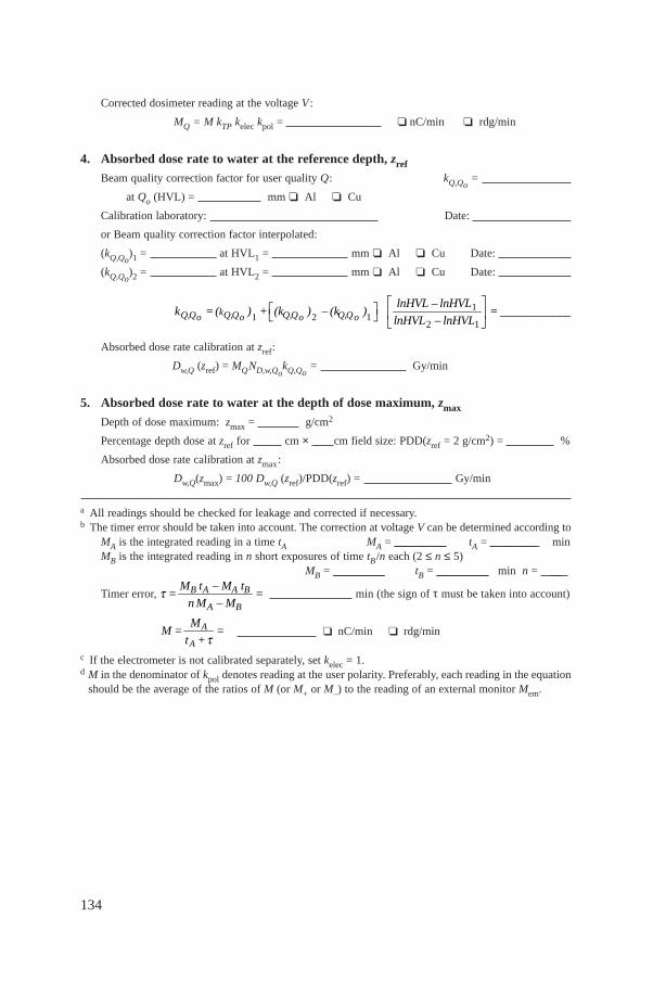
134
Corrected dosimeter reading at the voltage V :
MQ = M kTP kelec kpol = ❏ nC/min ❏ rdg/min
4. Absorbed dose rate to water at the reference depth, zref
Beam quality correction factor for user quality Q: kQ,Qo=
at Qo (HVL) = mm ❏ Al ❏ Cu
Calibration laboratory: Date:
or Beam quality correction factor interpolated:
(kQ,Qo)1 = at HVL1 = mm ❏ Al ❏ Cu Date:
(kQ,Qo)2 = at HVL2 = mm ❏ Al ❏ Cu Date:
Absorbed dose rate calibration at zref:
Dw,Q (zref) = MQND,w,QokQ,Qo
= Gy/min
5. Absorbed dose rate to water at the depth of dose maximum, zmax
Depth of dose maximum: zmax = g/cm2
Percentage depth dose at zref for cm × cm field size: PDD(zref = 2 g/cm2) = %
Absorbed dose rate calibration at zmax:
Dw,Q(zmax) = 100 Dw,Q (zref)/PDD(zref) = Gy/min
a All readings should be checked for leakage and corrected if necessary.b The timer error should be taken into account. The correction at voltage V can be determined according to
MA is the integrated reading in a time tA MA = _________ tA = ________ minMB is the integrated reading in n short exposures of time tB/n each (2 ≤ n ≤ 5)
MB = _________ tB = _________ min n = __
Timer error, min (the sign of τ must be taken into account)
❏ nC/min ❏ rdg/min
c If the electrometer is not calibrated separately, set kelec = 1.d M in the denominator of kpol denotes reading at the user polarity. Preferably, each reading in the equation
should be the average of the ratios of M (or M+ or M–) to the reading of an external monitor Mem.
A
A
MM = =
t +t
B A A B
A B
M t – M t= =
n M – Mt
11 2 1
2 1kQ,Q Q,Q Q,Q Q,Qo o o o
lnHVL – lnHVLk =( ) + (k ) – (k ) = ____________
lnHVL – lnHVL
È ˘È ˘ Í ˙Î ˚ Î ˚
135
10. CODE OF PRACTICE FOR PROTON BEAMS
10.1. GENERAL
This section provides a Code of Practice for reference dosimetry (beamcalibration) and recommendations for relative dosimetry in proton beams withenergies in the range from 50 MeV to 250 MeV. It is based upon a calibration factorin terms of absorbed dose to water ND,w,Qo
for a dosimeter in a reference beam ofquality Qo.43
At present, there are two main clinical applications for proton beams (seeRef. [107]). Relatively low energy protons (less than 90 MeV) are employed in thetreatment of ocular tumours using field sizes smaller than 4 cm × 4 cm and high doserates. Higher energy protons (above 150 MeV) are used for the treatment of large ordeep seated tumours. For these applications, field sizes and dose rates similar to thoseused with high energy photons are employed.
A typical depth dose distribution for a therapeutic proton beam is shown inFig. 14(a). This consists of a region where the dose increases slowly with depth,called the ‘plateau’, and a region where the dose rises rapidly to a maximum, calledthe ‘Bragg peak’. Clinical applications require a relatively uniform dose to be deliv-ered to the volume to be treated, and for this purpose the proton beam has to be spreadout both laterally and in depth. This is obtained at a treatment depth by the superpo-sition of Bragg peaks of different intensities and energies. The technique is called‘beam modulation’ and creates a region of high dose uniformity referred to as the‘spread-out Bragg peak’ (SOBP) (see Fig. 14(b)). The width of the SOBP is normallydefined by the width of the 95% dose levels. Spreading out of a Bragg peak can beachieved by different modulation techniques such as energy modulation [108] orraster scanning or dynamic spot scanning [107, 109]; for the latter, the beammodulation can be part of a more complex scanning technique in three dimensions.Some treatments use the plateau region to treat the target, with the Bragg peak fallingbeyond the distal side of the patient [110].
Clinical proton dosimetry to date has been based on different types ofdosimeters, such as calorimeters, ionization chambers, Faraday cups, track detec-tors, activation systems and diodes [108,111,112]. Existing proton dosimetry proto-cols [113–115] provide recommendations for ionization chamber dosimetry, based
43 As no primary standard of absorbed dose to water for proton beams is yet available,60Co gamma rays will be used as reference beam quality Qo for proton dosimetry (seeSection 10.5).
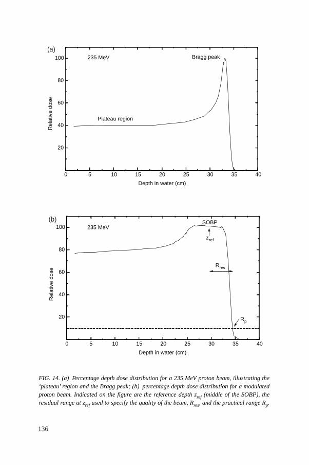
136
FIG. 14. (a) Percentage depth dose distribution for a 235 MeV proton beam, illustrating the‘plateau’ region and the Bragg peak; (b) percentage depth dose distribution for a modulatedproton beam. Indicated on the figure are the reference depth zref (middle of the SOBP), theresidual range at zref used to specify the quality of the beam, Rres, and the practical range Rp.
0 5 10 15 20 25 30 35 40
20
40
60
80
100 235 MeV
Plateau region
Bragg peakR
elat
ive
dose
Depth in water (cm)
(a)
0 5 10 15 20 25 30 35 40
20
40
60
80
100 235 MeV
Rres
Rp
zref
SOBP
Rel
ativ
e do
se
Depth in water (cm)
(b)
137
on in-air calibrations in a 60Co beam in terms of exposure or air kerma. Reference[116] discusses, in addition, the determination of absorbed dose in a proton beamusing ionization chambers calibrated in a 60Co beam in terms of absorbed dose towater; however, only a general description with little detail is provided.
10.2. DOSIMETRY EQUIPMENT
10.2.1. Ionization chambers
The recommendations regarding ionization chambers given in Section 4.2.1should be followed. Both cylindrical and plane-parallel ionization chambers arerecommended for use as reference instruments for the calibration of clinical protonbeams. However, the combined standard uncertainty in Dw for plane-parallel ioniza-tion chambers will be slightly higher than for cylindrical chambers due to their higheruncertainty for pwall in the 60Co reference beam quality (see Table 32 and AppendixII). For this reason, cylindrical ionization chambers are preferred for referencedosimetry; their use is, however, limited to proton beams with qualities at the refer-ence depth Rres ≥ 0.5 g/cm2. Graphite walled cylindrical chambers are preferable toplastic walled chambers because of their better long term stability and smallerchamber to chamber variations (see Section 4.2.1 and Fig. 2). The reference point forthese chambers is taken to be on the central axis of the chamber at the centre of thecavity volume; this point is positioned at the reference depth in the phantom.
Plane-parallel chambers can be used for reference dosimetry in all protonbeams, but must be used for proton beams with qualities at the reference depthRres < 0.5 g/cm2. For these chambers, the reference point is taken to be on the innersurface of the entrance window, at the centre of the window; this point is positionedat the point of interest in the phantom. The cavity diameter of the plane-parallelionization chamber or the cavity length of the cylindrical ionization chamber shouldnot be larger than approximately half the reference field size. Moreover, the outerdiameter for cylindrical ionization chambers should not be larger than half theSOBP width.
For relative dosimetry, only plane-parallel ionization chambers are recom-mended. The chamber types for which data are given in this Code of Practice arelisted in Table 31 of Section 10.5.
10.2.2. Phantoms and chamber sleeves
The recommendations regarding phantoms and chamber sleeves given inSections 4.2.3 and 4.2.4 should be followed. Water is recommended as the reference
138
medium for the determination of absorbed dose and for beam quality measurementswith proton beams. The phantom should extend to at least 5 cm beyond all four sidesof the field size employed at the depth of measurement and also extend to at least5 g/cm2 beyond the maximum depth of measurement.
In horizontal beams, the window of the phantom should be made of plastic andof thickness twin between 0.2 and 0.5 cm. The water equivalent thickness (in g/cm2)of the phantom window should be taken into account when evaluating the depth atwhich the chamber is to be positioned; the thickness is calculated as the producttwin ρpl where ρpl is the mass density of the plastic (in g/cm3). For the commonly usedplastics PMMA and clear polystyrene, the nominal values ρPMMA = 1.19 g/cm3 andρpolystyrene = 1.06 g/cm–3 [64] may be used for the calculation of the water equivalentthickness of the window.
For non-waterproof chambers a waterproofing sleeve should be used, made ofPMMA, and preferably not thicker than 1.0 mm. The air gap between the chamberwall and the waterproofing sleeve should be sufficient (0.1–0.3 mm) to allow the airpressure in the chamber to equilibrate. The same waterproofing sleeve that was usedfor calibration of the user’s ionization chamber should also be used for referencedosimetry. If it is not possible to use the same waterproofing sleeve that was usedduring calibration at the standardizing laboratory, then another sleeve of the samematerial and of similar thickness should be used. Plane-parallel chambers, if notinherently waterproof or supplied with a waterproof cover, must be used in a water-proof enclosure, preferably of PMMA or a material that closely matches the chamberwalls; ideally, there should be no more than 1 mm of added material in front of andbehind the cavity volume.
Plastic phantoms should not be used for reference dosimetry in proton beamssince the required water to plastic fluence correction factors, hpl, are not known.Information on the use of plastic phantoms for relative dosimetry is given inSection 10.6.3.
10.3. BEAM QUALITY SPECIFICATION
10.3.1. Choice of beam quality index
In previous proton dosimetry protocols and recommendations [114–116], theproton beam quality was specified by the effective energy, which is defined as theenergy of a monoenergetic proton beam having a range equal to the residual rangeRres of the clinical proton beam (see definition below). This choice was justified bythe small energy dependence of water/air stopping-power ratios (see Fig. 21) and bythe fact that the effective energy is close to the maximum energy in the proton energyspectrum at the reference depth (see reference conditions in Tables 29 and 30).
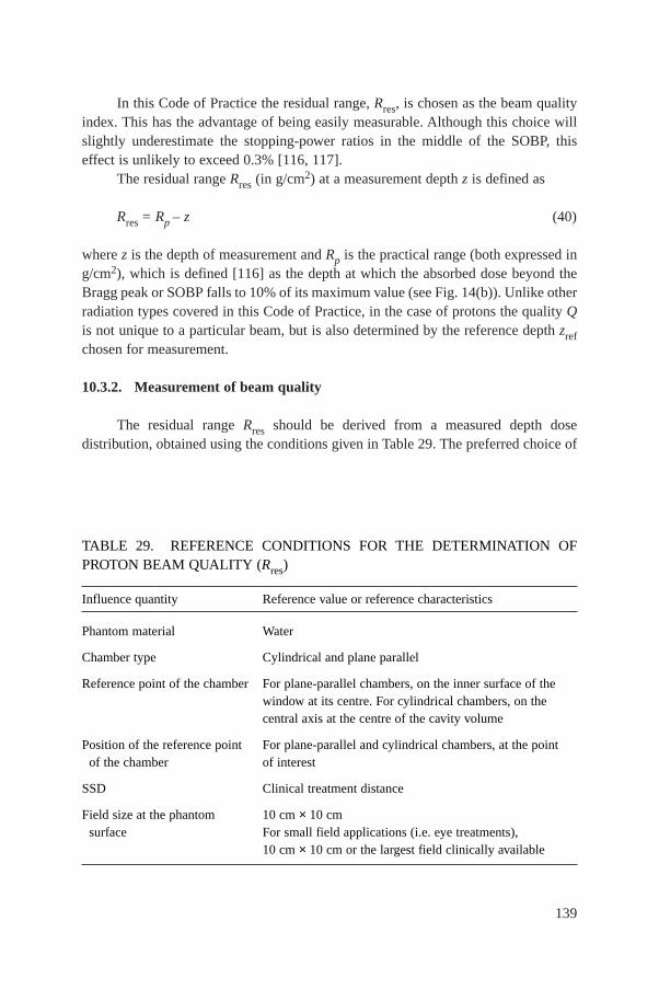
139
In this Code of Practice the residual range, Rres, is chosen as the beam qualityindex. This has the advantage of being easily measurable. Although this choice willslightly underestimate the stopping-power ratios in the middle of the SOBP, thiseffect is unlikely to exceed 0.3% [116, 117].
The residual range Rres (in g/cm2) at a measurement depth z is defined as
Rres = Rp – z (40)
where z is the depth of measurement and Rp is the practical range (both expressed ing/cm2), which is defined [116] as the depth at which the absorbed dose beyond theBragg peak or SOBP falls to 10% of its maximum value (see Fig. 14(b)). Unlike otherradiation types covered in this Code of Practice, in the case of protons the quality Qis not unique to a particular beam, but is also determined by the reference depth zrefchosen for measurement.
10.3.2. Measurement of beam quality
The residual range Rres should be derived from a measured depth dosedistribution, obtained using the conditions given in Table 29. The preferred choice of
TABLE 29. REFERENCE CONDITIONS FOR THE DETERMINATION OFPROTON BEAM QUALITY (Rres)
Influence quantity Reference value or reference characteristics
Phantom material Water
Chamber type Cylindrical and plane parallel
Reference point of the chamber For plane-parallel chambers, on the inner surface of the window at its centre. For cylindrical chambers, on the central axis at the centre of the cavity volume
Position of the reference point For plane-parallel and cylindrical chambers, at the point of the chamber of interest
SSD Clinical treatment distance
Field size at the phantom 10 cm × 10 cmsurface For small field applications (i.e. eye treatments),
10 cm × 10 cm or the largest field clinically available
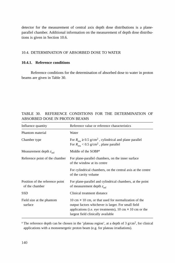
140
detector for the measurement of central axis depth dose distributions is a plane-parallel chamber. Additional information on the measurement of depth dose distribu-tions is given in Section 10.6.
10.4. DETERMINATION OF ABSORBED DOSE TO WATER
10.4.1. Reference conditions
Reference conditions for the determination of absorbed dose to water in protonbeams are given in Table 30.
TABLE 30. REFERENCE CONDITIONS FOR THE DETERMINATION OFABSORBED DOSE IN PROTON BEAMS
Influence quantity Reference value or reference characteristics
Phantom material Water
Chamber type For Rres ≥ 0.5 g/cm2 , cylindrical and plane parallelFor Rres < 0.5 g/cm2 , plane parallel
Measurement depth zref Middle of the SOBPa
Reference point of the chamber For plane-parallel chambers, on the inner surface of the window at its centre
For cylindrical chambers, on the central axis at the centre of the cavity volume
Position of the reference point For plane-parallel and cylindrical chambers, at the point of the chamber of measurement depth zref
SSD Clinical treatment distance
Field size at the phantom 10 cm × 10 cm, or that used for normalization of the surface output factors whichever is larger. For small field
applications (i.e. eye treatments), 10 cm × 10 cm or the largest field clinically available
a The reference depth can be chosen in the ‘plateau region’, at a depth of 3 g/cm2, for clinicalapplications with a monoenergetic proton beam (e.g. for plateau irradiations).
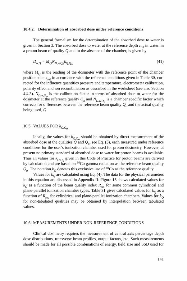
141
10.4.2. Determination of absorbed dose under reference conditions
The general formalism for the determination of the absorbed dose to water isgiven in Section 3. The absorbed dose to water at the reference depth zref in water, ina proton beam of quality Q and in the absence of the chamber, is given by
Dw,Q = MQND,w,QokQ,Qo
(41)
where MQ is the reading of the dosimeter with the reference point of the chamberpositioned at zref in accordance with the reference conditions given in Table 30, cor-rected for the influence quantities pressure and temperature, electrometer calibration,polarity effect and ion recombination as described in the worksheet (see also Section4.4.3). ND,w,Qo
is the calibration factor in terms of absorbed dose to water for thedosimeter at the reference quality Qo and ND,w,Qo
is a chamber specific factor whichcorrects for differences between the reference beam quality Qo and the actual qualitybeing used, Q.
10.5. VALUES FOR kQ,Qo
Ideally, the values for kQ,Qoshould be obtained by direct measurement of the
absorbed dose at the qualities Q and Qo, see Eq. (3), each measured under referenceconditions for the user’s ionization chamber used for proton dosimetry. However, atpresent no primary standard of absorbed dose to water for proton beams is available.Thus all values for kQ,Qo
given in this Code of Practice for proton beams are derivedby calculation and are based on 60Co gamma radiation as the reference beam qualityQo. The notation kQ denotes this exclusive use of 60Co as the reference quality.
Values for kQ are calculated using Eq. (4). The data for the physical parametersin this equation are discussed in Appendix II. Figure 15 shows calculated values forkQ as a function of the beam quality index Rres for some common cylindrical andplane-parallel ionization chamber types. Table 31 gives calculated values for kQ as afunction of Rres for cylindrical and plane-parallel ionization chambers. Values for kQfor non-tabulated qualities may be obtained by interpolation between tabulatedvalues.
10.6. MEASUREMENTS UNDER NON-REFERENCE CONDITIONS
Clinical dosimetry requires the measurement of central axis percentage depthdose distributions, transverse beam profiles, output factors, etc. Such measurementsshould be made for all possible combinations of energy, field size and SSD used for
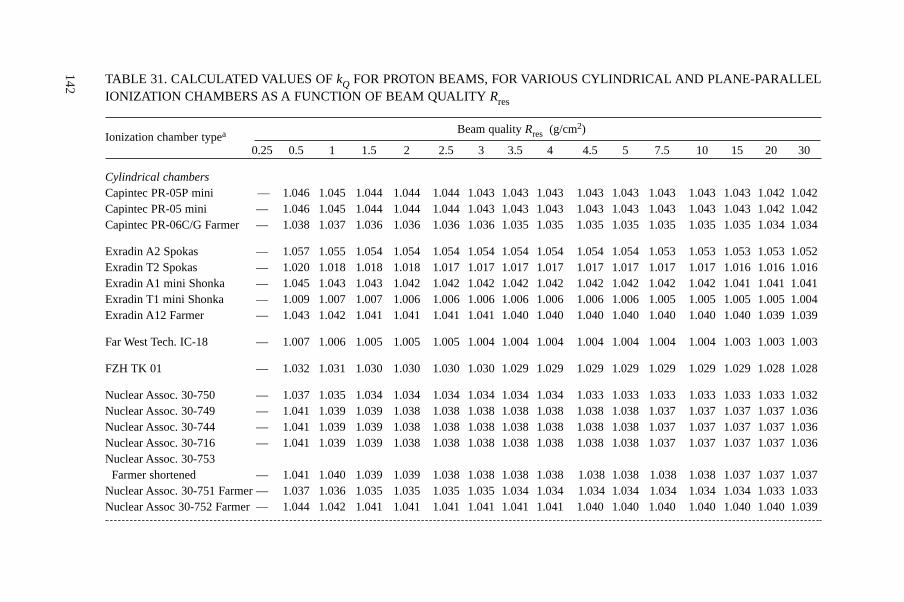
142 TABLE 31. CALCULATED VALUES OF kQ FOR PROTON BEAMS, FOR VARIOUS CYLINDRICAL AND PLANE-PARALLELIONIZATION CHAMBERS AS A FUNCTION OF BEAM QUALITY Rres
Ionization chamber typea Beam quality Rres (g/cm2)
0.25 0.5 1 1.5 2 2.5 3 3.5 4 4.5 5 7.5 10 15 20 30
Cylindrical chambersCapintec PR-05P mini — 1.046 1.045 1.044 1.044 1.044 1.043 1.043 1.043 1.043 1.043 1.043 1.043 1.043 1.042 1.042Capintec PR-05 mini — 1.046 1.045 1.044 1.044 1.044 1.043 1.043 1.043 1.043 1.043 1.043 1.043 1.043 1.042 1.042Capintec PR-06C/G Farmer — 1.038 1.037 1.036 1.036 1.036 1.036 1.035 1.035 1.035 1.035 1.035 1.035 1.035 1.034 1.034
Exradin A2 Spokas — 1.057 1.055 1.054 1.054 1.054 1.054 1.054 1.054 1.054 1.054 1.053 1.053 1.053 1.053 1.052Exradin T2 Spokas — 1.020 1.018 1.018 1.018 1.017 1.017 1.017 1.017 1.017 1.017 1.017 1.017 1.016 1.016 1.016Exradin A1 mini Shonka — 1.045 1.043 1.043 1.042 1.042 1.042 1.042 1.042 1.042 1.042 1.042 1.042 1.041 1.041 1.041Exradin T1 mini Shonka — 1.009 1.007 1.007 1.006 1.006 1.006 1.006 1.006 1.006 1.006 1.005 1.005 1.005 1.005 1.004Exradin A12 Farmer — 1.043 1.042 1.041 1.041 1.041 1.041 1.040 1.040 1.040 1.040 1.040 1.040 1.040 1.039 1.039
Far West Tech. IC-18 — 1.007 1.006 1.005 1.005 1.005 1.004 1.004 1.004 1.004 1.004 1.004 1.004 1.003 1.003 1.003
FZH TK 01 — 1.032 1.031 1.030 1.030 1.030 1.030 1.029 1.029 1.029 1.029 1.029 1.029 1.029 1.028 1.028
Nuclear Assoc. 30-750 — 1.037 1.035 1.034 1.034 1.034 1.034 1.034 1.034 1.033 1.033 1.033 1.033 1.033 1.033 1.032Nuclear Assoc. 30-749 — 1.041 1.039 1.039 1.038 1.038 1.038 1.038 1.038 1.038 1.038 1.037 1.037 1.037 1.037 1.036Nuclear Assoc. 30-744 — 1.041 1.039 1.039 1.038 1.038 1.038 1.038 1.038 1.038 1.038 1.037 1.037 1.037 1.037 1.036Nuclear Assoc. 30-716 — 1.041 1.039 1.039 1.038 1.038 1.038 1.038 1.038 1.038 1.038 1.037 1.037 1.037 1.037 1.036Nuclear Assoc. 30-753
Farmer shortened — 1.041 1.040 1.039 1.039 1.038 1.038 1.038 1.038 1.038 1.038 1.038 1.038 1.037 1.037 1.037Nuclear Assoc. 30-751 Farmer — 1.037 1.036 1.035 1.035 1.035 1.035 1.034 1.034 1.034 1.034 1.034 1.034 1.034 1.033 1.033Nuclear Assoc 30-752 Farmer — 1.044 1.042 1.041 1.041 1.041 1.041 1.041 1.041 1.040 1.040 1.040 1.040 1.040 1.040 1.039
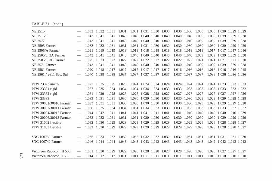
143
TABLE 31. (cont.)
NE 2515 — 1.033 1.032 1.031 1.031 1.031 1.031 1.030 1.030 1.030 1.030 1.030 1.030 1.030 1.029 1.029NE 2515/3 — 1.043 1.041 1.041 1.040 1.040 1.040 1.040 1.040 1.040 1.040 1.039 1.039 1.039 1.039 1.038NE 2577 — 1.043 1.041 1.041 1.040 1.040 1.040 1.040 1.040 1.040 1.040 1.039 1.039 1.039 1.039 1.038NE 2505 Farmer — 1.033 1.032 1.031 1.031 1.031 1.031 1.030 1.030 1.030 1.030 1.030 1.030 1.030 1.029 1.029NE 2505/A Farmer — 1.021 1.019 1.019 1.018 1.018 1.018 1.018 1.018 1.018 1.018 1.018 1.017 1.017 1.017 1.016NE 2505/3, 3A Farmer — 1.043 1.041 1.041 1.040 1.040 1.040 1.040 1.040 1.040 1.040 1.039 1.039 1.039 1.039 1.038NE 2505/3, 3B Farmer — 1.025 1.023 1.023 1.022 1.022 1.022 1.022 1.022 1.022 1.022 1.021 1.021 1.021 1.021 1.020NE 2571 Farmer — 1.043 1.041 1.041 1.040 1.040 1.040 1.040 1.040 1.040 1.040 1.039 1.039 1.039 1.039 1.038NE 2581 Farmer — 1.020 1.018 1.017 1.017 1.017 1.017 1.017 1.017 1.016 1.016 1.016 1.016 1.016 1.016 1.015NE 2561 / 2611 Sec. Std — 1.040 1.038 1.038 1.037 1.037 1.037 1.037 1.037 1.037 1.037 1.037 1.036 1.036 1.036 1.036
PTW 23323 micro — 1.027 1.025 1.025 1.025 1.024 1.024 1.024 1.024 1.024 1.024 1.024 1.024 1.023 1.023 1.023PTW 23331 rigid — 1.037 1.035 1.034 1.034 1.034 1.034 1.034 1.033 1.033 1.033 1.033 1.033 1.033 1.033 1.032PTW 23332 rigid — 1.031 1.029 1.028 1.028 1.028 1.028 1.028 1.027 1.027 1.027 1.027 1.027 1.027 1.027 1.026PTW 23333 — 1.033 1.031 1.031 1.030 1.030 1.030 1.030 1.030 1.030 1.030 1.029 1.029 1.029 1.029 1.028PTW 30001/30010 Farmer — 1.033 1.031 1.031 1.030 1.030 1.030 1.030 1.030 1.030 1.030 1.029 1.029 1.029 1.029 1.028PTW 30002/30011 Farmer — 1.036 1.035 1.034 1.034 1.034 1.034 1.033 1.033 1.033 1.033 1.033 1.033 1.033 1.032 1.032PTW 30004/30012 Farmer — 1.044 1.042 1.041 1.041 1.041 1.041 1.041 1.041 1.041 1.040 1.040 1.040 1.040 1.040 1.039PTW 30006/30013 Farmer — 1.033 1.032 1.031 1.031 1.031 1.030 1.030 1.030 1.030 1.030 1.030 1.030 1.029 1.029 1.029PTW 31002 flexible — 1.032 1.030 1.029 1.029 1.029 1.029 1.029 1.029 1.029 1.029 1.028 1.028 1.028 1.028 1.027PTW 31003 flexible — 1.032 1.030 1.029 1.029 1.029 1.029 1.029 1.029 1.029 1.029 1.028 1.028 1.028 1.028 1.027
SNC 100730 Farmer — 1.035 1.033 1.032 1.032 1.032 1.032 1.032 1.032 1.032 1.031 1.031 1.031 1.031 1.031 1.030SNC 100740 Farmer — 1.046 1.044 1.044 1.043 1.043 1.043 1.043 1.043 1.043 1.043 1.043 1.042 1.042 1.042 1.042
Victoreen Radocon III 550 — 1.031 1.030 1.029 1.029 1.028 1.028 1.028 1.028 1.028 1.028 1.028 1.028 1.027 1.027 1.027Victoreen Radocon II 555 — 1.014 1.012 1.012 1.011 1.011 1.011 1.011 1.011 1.011 1.011 1.011 1.010 1.010 1.010 1.010
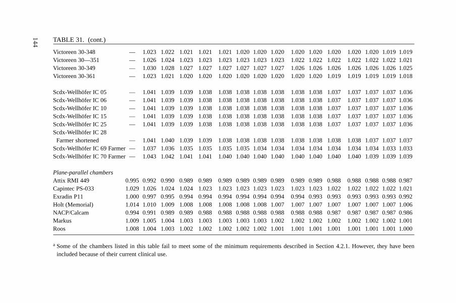
144 TABLE 31. (cont.)
Victoreen 30-348 — 1.023 1.022 1.021 1.021 1.021 1.020 1.020 1.020 1.020 1.020 1.020 1.020 1.020 1.019 1.019Victoreen 30—351 — 1.026 1.024 1.023 1.023 1.023 1.023 1.023 1.023 1.022 1.022 1.022 1.022 1.022 1.022 1.021Victoreen 30-349 — 1.030 1.028 1.027 1.027 1.027 1.027 1.027 1.027 1.026 1.026 1.026 1.026 1.026 1.026 1.025Victoreen 30-361 — 1.023 1.021 1.020 1.020 1.020 1.020 1.020 1.020 1.020 1.020 1.019 1.019 1.019 1.019 1.018
Scdx-Wellhöfer IC 05 — 1.041 1.039 1.039 1.038 1.038 1.038 1.038 1.038 1.038 1.038 1.037 1.037 1.037 1.037 1.036Scdx-Wellhöfer IC 06 — 1.041 1.039 1.039 1.038 1.038 1.038 1.038 1.038 1.038 1.038 1.037 1.037 1.037 1.037 1.036Scdx-Wellhöfer IC 10 — 1.041 1.039 1.039 1.038 1.038 1.038 1.038 1.038 1.038 1.038 1.037 1.037 1.037 1.037 1.036Scdx-Wellhöfer IC 15 — 1.041 1.039 1.039 1.038 1.038 1.038 1.038 1.038 1.038 1.038 1.037 1.037 1.037 1.037 1.036Scdx-Wellhöfer IC 25 — 1.041 1.039 1.039 1.038 1.038 1.038 1.038 1.038 1.038 1.038 1.037 1.037 1.037 1.037 1.036Scdx-Wellhöfer IC 28
Farmer shortened — 1.041 1.040 1.039 1.039 1.038 1.038 1.038 1.038 1.038 1.038 1.038 1.038 1.037 1.037 1.037Scdx-Wellhöfer IC 69 Farmer — 1.037 1.036 1.035 1.035 1.035 1.035 1.034 1.034 1.034 1.034 1.034 1.034 1.034 1.033 1.033Scdx-Wellhöfer IC 70 Farmer — 1.043 1.042 1.041 1.041 1.040 1.040 1.040 1.040 1.040 1.040 1.040 1.040 1.039 1.039 1.039
Plane-parallel chambersAttix RMI 449 0.995 0.992 0.990 0.989 0.989 0.989 0.989 0.989 0.989 0.989 0.989 0.988 0.988 0.988 0.988 0.987Capintec PS-033 1.029 1.026 1.024 1.024 1.023 1.023 1.023 1.023 1.023 1.023 1.023 1.022 1.022 1.022 1.022 1.021Exradin P11 1.000 0.997 0.995 0.994 0.994 0.994 0.994 0.994 0.994 0.994 0.993 0.993 0.993 0.993 0.993 0.992Holt (Memorial) 1.014 1.010 1.009 1.008 1.008 1.008 1.008 1.008 1.007 1.007 1.007 1.007 1.007 1.007 1.007 1.006NACP/Calcam 0.994 0.991 0.989 0.989 0.988 0.988 0.988 0.988 0.988 0.988 0.988 0.987 0.987 0.987 0.987 0.986Markus 1.009 1.005 1.004 1.003 1.003 1.003 1.003 1.003 1.002 1.002 1.002 1.002 1.002 1.002 1.002 1.001Roos 1.008 1.004 1.003 1.002 1.002 1.002 1.002 1.002 1.001 1.001 1.001 1.001 1.001 1.001 1.001 1.000
a Some of the chambers listed in this table fail to meet some of the minimum requirements described in Section 4.2.1. However, they have beenincluded because of their current clinical use.
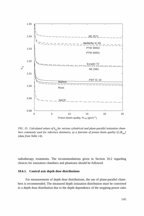
145
radiotherapy treatments. The recommendations given in Section 10.2 regardingchoices for ionization chambers and phantoms should be followed.
10.6.1. Central axis depth dose distributions
For measurements of depth dose distributions, the use of plane-parallel cham-bers is recommended. The measured depth ionization distribution must be convertedto a depth dose distribution due to the depth dependence of the stopping-power ratio
FIG. 15. Calculated values of kQ for various cylindrical and plane-parallel ionization cham-bers commonly used for reference dosimetry, as a function of proton beam quality Q (Rres)(data from Table 14).
Proton beam quality, R res (g/cm 2 )
0 5 10 15 20 25
kQ
0.98
0.99
1.00
1.01
1.02
1.03
1.04
1.05
NACP
Markus
NE 2571
Wellhöfer IC 69
PTW 30002
PTW 30001
NE 2581
Exradin T2
FWT IC-18
Roos
MarkusFWT IC 18
146
sw,air, particularly in the low energy region. This is achieved by multiplying themeasured ionization charge or current at each depth z by the stopping-power ratiosw,air and the perturbation factor at that depth. Values for sw,air as a function of Rres canbe calculated from Eq. (73) given in Appendix II. Perturbation factors are assumed tohave a value of unity (see Appendix II). The influence of ion recombination andpolarity effects on the depth ionization distribution should be investigated and takeninto account if there is a variation with depth.
If the field size for which measurements are to be performed is smaller thantwice the diameter of the cavity of the plane-parallel chamber, then a detector with abetter spatial resolution (e.g. mini-chamber, diode or diamond) is recommended. Theresulting distribution must also be converted using the appropriate stopping-powerratios (e.g. water to air, water to silicon or water to graphite). For the latter, thenecessary stopping-power values can be found in Ref. [118]. The suitability of suchdetectors for depth dose measurements should be verified by test comparisons with aplane-parallel chamber at a larger field size.
For clinical proton beams produced by dynamic beam delivery systems (i.e.spot scanning), measurement times should be long enough compared to the scanningcycle of the field in order to yield reproducible readings.
10.6.2. Output factors
The output factor may be determined as the ratio of corrected dosimeter read-ings at the reference depth zref measured under a given set of non-reference conditionsrelative to that measured under reference conditions (reference conditions are givenin Table 30). For a given proton beam, output factors should be measured for all non-reference field sizes and SSDs used for patient treatments.
10.6.3. Use of plastic phantoms for relative dosimetry
The use of plastic phantoms is strongly discouraged as, in general, they areresponsible for discrepancies in the determination of absorbed dose. Plastic phantomsshould not be used for reference dosimetry in proton beams since the required waterto plastic fluence correction factors, hpl, are not known. Nevertheless, when accuratechamber positioning in water is not possible or when no waterproof chamber isavailable, their use is permitted for the measurement of depth dose distribution forlow energy proton beams (approximately below 100 MeV). In this case, the dosimeterreading at each plastic depth should be scaled using the fluence scaling factor hpl. Itis assumed that hpl has constant value of unity at all depths.
The criteria determining the choice of plastic materials are discussed inSection 4.2.3. The density of the plastic, ρpl, should be measured for the batch ofplastic in use rather than using a nominal value for the plastic type. Each
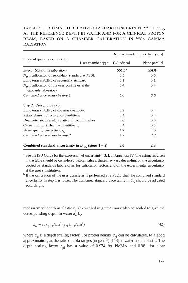
147
measurement depth in plastic zpl (expressed in g/cm2) must also be scaled to give thecorresponding depth in water zw by
zw = zplcpl g/cm2 (zpl in g/cm2) (42)
where cpl is a depth scaling factor. For proton beams, cpl can be calculated, to a goodapproximation, as the ratio of csda ranges (in g/cm2) [118] in water and in plastic. Thedepth scaling factor cpl has a value of 0.974 for PMMA and 0.981 for clear
TABLE 32. ESTIMATED RELATIVE STANDARD UNCERTAINTYa OF Dw,QAT THE REFERENCE DEPTH IN WATER AND FOR A CLINICAL PROTONBEAM, BASED ON A CHAMBER CALIBRATION IN 60Co GAMMARADIATION
Physical quantity or procedureRelative standard uncertainty (%)
User chamber type: Cylindrical Plane parallel
Step 1: Standards laboratory SSDLb SSDLb
ND,w calibration of secondary standard at PSDL 0.5 0.5Long term stability of secondary standard 0.1 0.1ND,w calibration of the user dosimeter at the 0.4 0.4
standards laboratoryCombined uncertainty in step 1 0.6 0.6
Step 2: User proton beamLong term stability of the user dosimeter 0.3 0.4Establishment of reference conditions 0.4 0.4Dosimeter reading MQ relative to beam monitor 0.6 0.6Correction for influence quantities ki 0.4 0.5Beam quality correction, kQ 1.7 2.0Combined uncertainty in step 2 1.9 2.2
Combined standard uncertainty in Dw,Q (steps 1 + 2) 2.0 2.3
a See the ISO Guide for the expression of uncertainty [32], or Appendix IV. The estimates givenin the table should be considered typical values; these may vary depending on the uncertaintyquoted by standards laboratories for calibration factors and on the experimental uncertaintyat the user’s institution.
b If the calibration of the user dosimeter is performed at a PSDL then the combined standarduncertainty in step 1 is lower. The combined standard uncertainty in Dw should be adjustedaccordingly.
148
polystyrene. The procedure given in Section 10.6.1 should be followed to generatecentral axis depth dose distributions from the measure depth ionization distributions.
If a plastic phantom is used to measure the beam quality index, the measuredquantity is the residual range in the plastic, Rres,pl. The residual range, Rres, in wateris also obtained using the scaling Eq. (42).
10.7. ESTIMATED UNCERTAINTY IN THE DETERMINATION OF ABSORBED DOSE TO WATER UNDER REFERENCE CONDITIONS
The uncertainties associated with the physical quantities and proceduresinvolved in the determination of the absorbed dose to water in the user proton beamcan be divided into two steps. Step 1 considers uncertainties up to the calibration ofthe user chamber in terms of ND,w at a standards laboratory. Step 2 deals with thesubsequent calibration of the user proton beam using this chamber and includes theuncerainty of kQ as well as that associated with measurements at the reference depthin a water phantom. Estimates of the uncertainties in these two steps are given inTable 32, yielding a combined standard uncerainty of 2% and 2.3% for the determi-nation of the absorbed dose to water in a clinical proton beam with a cylindrical andplane-parallel ionization chamber, respectively. Details on the uncertainty estimatesfor the various physical parameters entering in the calculation of kQ are given inAppendix II.
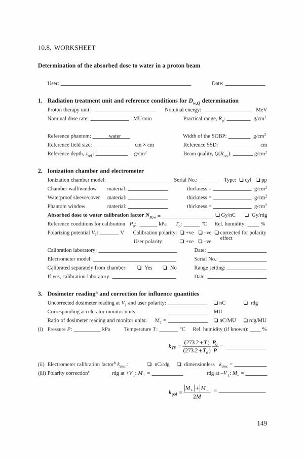
149
10.8. WORKSHEET
Determination of the absorbed dose to water in a proton beam
User: Date:
1. Radiation treatment unit and reference conditions for Dw,Q determination
Proton therapy unit: Nominal energy: MeV
Nominal dose rate: MU/min Practical range, Rp: g/cm2
Reference phantom: water Width of the SOBP: g/cm2
Reference field size: cm × cm Reference SSD: cm
Reference depth, zref: g/cm2 Beam quality, Q(Rres): g/cm2
2. Ionization chamber and electrometer
Ionization chamber model: Serial No.: Type: ❏ cyl ❏ pp
Chamber wall/window material: thickness = g/cm2
Waterproof sleeve/cover material: thickness = g/cm2
Phantom window material: thickness = g/cm2
Absorbed dose to water calibration factor ND,w = ❏ Gy/nC ❏ Gy/rdg
Reference conditions for calibration Po: kPa To: °C Rel. humidity: %
Polarizing potential V1: V Calibration polarity: ❏ +ve ❏ –ve ❏ corrected for polarity
User polarity: ❏ +ve ❏ –ve effect
Calibration laboratory: Date:
Electrometer model: Serial No.:
Calibrated separately from chamber: ❏ Yes ❏ No Range setting:
If yes, calibration laboratory: Date:
3. Dosimeter readinga and correction for influence quantities
Uncorrected dosimeter reading at V1 and user polarity: ❏ nC ❏ rdg
Corresponding accelerator monitor units: MU
Ratio of dosimeter reading and monitor units: M1 = ❏ nC/MU ❏ rdg/MU
(i) Pressure P: __________ kPa Temperature T : _______ °C Rel. humidity (if known): ____ %
(ii) Electrometer calibration factorb kelec: ❏ nC/rdg ❏ dimensionless kelec =
(iii) Polarity correctionc rdg at +V 1: M+ = rdg at –V 1: M– =
= kM M
Mpol =++ -
2
kT
T
P
PTPo
o= ++
=( . )
( . )
273 2
273 2
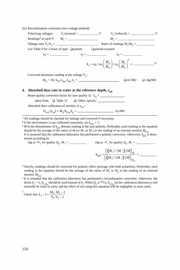
150
(iv) Recombination correction (two voltage method)
Polarizing voltages: Vl (normal) = ____________ V V2 (reduced) = _______________ V
Readingsd at each V: M1 = ___________________ M2 = _______________________
Voltage ratio V1/V2 = __________________________ Ratio of readings M1/M2 = ___________
Use Table 9 for a beam of type: ❏ pulsed ❏ pulsed-scanned
a0 = ____________ a1 = ____________ a2 = ____________
_____________e,f
Corrected dosimeter reading at the voltage V1:
MQ = M1 kTP kelec kpol ks = ❏ nC/MU ❏ rdg/MU
4. Absorbed dose rate to water at the reference depth, zref
Beam quality correction factor for user quality Q: kQ =
taken from ❏ Table 31 ❏ Other, specify:
Absorbed dose calibration of monitor at zref:
Dw,Q (zref) = MQND,w,kQ = Gy/MU
a All readings should be checked for leakage and corrected if necessary.b If the electrometer is not calibrated separately, set kelec = 1.c M in the denominator of kpol denotes reading at the user polarity. Preferably, each reading in the equation
should be the average of the ratios of M (or M+ or M–) to the reading of an external monitor Mem.It is assumed that the calibration laboratory has performed a polarity correction. Otherwise, kpol is deter-mined according to:
rdg at +V1 for quality Qo: M+ = ___________ rdg at –V1 for quality Qo: M– = ____________
d Strictly, readings should be corrected for polarity effect (average with both polarities). Preferably, eachreading in the equation should be the average of the ratios of M1 or M2 to the reading of an externalmonitor Mem.
e It is assumed that the calibration laboratory has performed a recombination correction. Otherwise, thefactor k′s = ks /ks,Qo
should be used instead of ks. When Qo is 60Co, ks,Qo(at the calibration laboratory) will
normally be close to unity and the effect of not using this equation will be negligible in most cases.
fCheck that 1 2
1 2
11
1sM M –
k –V V –
ª
( )( )pol
+ –
+ –
Q
Qo
M + M Mk = = ___________
M + M M
È ˘Î ˚È ˘Î ˚
k a aM
Ma
M
Ms = +ÊËÁ
ˆ¯̃
+ÊËÁ
ˆ¯̃
=0 11
22
1
2
2
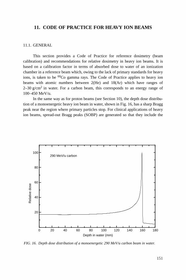
151
11. CODE OF PRACTICE FOR HEAVY ION BEAMS
11.1. GENERAL
This section provides a Code of Practice for reference dosimetry (beamcalibration) and recommendations for relative dosimetry in heavy ion beams. It isbased on a calibration factor in terms of absorbed dose to water of an ionizationchamber in a reference beam which, owing to the lack of primary standards for heavyions, is taken to be 60Co gamma rays. The Code of Practice applies to heavy ionbeams with atomic numbers between 2(He) and 18(Ar) which have ranges of2–30 g/cm2 in water. For a carbon beam, this corresponds to an energy range of100–450 MeV/u.
In the same way as for proton beams (see Section 10), the depth dose distribu-tion of a monoenergetic heavy ion beam in water, shown in Fig. 16, has a sharp Braggpeak near the region where primary particles stop. For clinical applications of heavyion beams, spread-out Bragg peaks (SOBP) are generated so that they include the
FIG. 16. Depth dose distribution of a monoenergetic 290 MeV/u carbon beam in water.
20
40
60
80
100
Rel
ativ
e do
se
Depth in water (mm)
0 20 40 60 80 100 120 140 160 180
290 MeV/u carbon
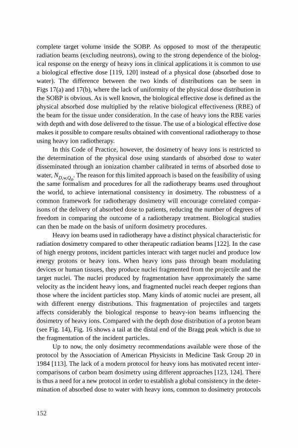
152
complete target volume inside the SOBP. As opposed to most of the therapeuticradiation beams (excluding neutrons), owing to the strong dependence of the biolog-ical response on the energy of heavy ions in clinical applications it is common to usea biological effective dose [119, 120] instead of a physical dose (absorbed dose towater). The difference between the two kinds of distributions can be seen inFigs 17(a) and 17(b), where the lack of uniformity of the physical dose distribution inthe SOBP is obvious. As is well known, the biological effective dose is defined as thephysical absorbed dose multiplied by the relative biological effectiveness (RBE) ofthe beam for the tissue under consideration. In the case of heavy ions the RBE varieswith depth and with dose delivered to the tissue. The use of a biological effective dosemakes it possible to compare results obtained with conventional radiotherapy to thoseusing heavy ion radiotherapy.
In this Code of Practice, however, the dosimetry of heavy ions is restricted tothe determination of the physical dose using standards of absorbed dose to waterdisseminated through an ionization chamber calibrated in terms of absorbed dose towater, ND,w,Qo
. The reason for this limited approach is based on the feasibility of usingthe same formalism and procedures for all the radiotherapy beams used throughoutthe world, to achieve international consistency in dosimetry. The robustness of acommon framework for radiotherapy dosimetry will encourage correlated compar-isons of the delivery of absorbed dose to patients, reducing the number of degrees offreedom in comparing the outcome of a radiotherapy treatment. Biological studiescan then be made on the basis of uniform dosimetry procedures.
Heavy ion beams used in radiotherapy have a distinct physical characteristic forradiation dosimetry compared to other therapeutic radiation beams [122]. In the caseof high energy protons, incident particles interact with target nuclei and produce lowenergy protons or heavy ions. When heavy ions pass through beam modulatingdevices or human tissues, they produce nuclei fragmented from the projectile and thetarget nuclei. The nuclei produced by fragmentation have approximately the samevelocity as the incident heavy ions, and fragmented nuclei reach deeper regions thanthose where the incident particles stop. Many kinds of atomic nuclei are present, allwith different energy distributions. This fragmentation of projectiles and targetsaffects considerably the biological response to heavy-ion beams influencing thedosimetry of heavy ions. Compared with the depth dose distribution of a proton beam(see Fig. 14), Fig. 16 shows a tail at the distal end of the Bragg peak which is due tothe fragmentation of the incident particles.
Up to now, the only dosimetry recommendations available were those of theprotocol by the Association of American Physicists in Medicine Task Group 20 in1984 [113]. The lack of a modern protocol for heavy ions has motivated recent inter-comparisons of carbon beam dosimetry using different approaches [123, 124]. Thereis thus a need for a new protocol in order to establish a global consistency in the deter-mination of absorbed dose to water with heavy ions, common to dosimetry protocols
153
FIG. 17. (a) Biological dose distributions of therapeutic carbon beams of energy 290 MeV/u.SOBPs of 20 to 120 mm width are designed to yield uniform biological effect in the peaks; (b) physical dose distributions of the beam shown in (a) .
20
40
60
80
100
Depth in water (mm)
0 20 40 60 80 100 120 140 160 180
20406080100120SOBP widthR
elat
ive
biol
ogic
al d
ose
(a)
20
40
60
80
100
Depth in water (mm)
0 20 40 60 80 100 120 140 160 180
Rel
ativ
e ph
ysic
al d
ose
10
30
50
70
90
110
20
4060
80100120SOBP width
(b)
154
for other radiotherapy beams. Absorbed dose in heavy ion beams can be measuredusing an ionization chamber or a calorimeter. Fluence measurement methods can alsobe applied for the determination of the absorbed dose of monoenergetic beams [113].In this Code of Practice only the method based on ionometric measurements isdiscussed.
For an accurate determination of absorbed dose from heavy ion beams using anionization chamber, it is desirable to know the energy spectra of the incident heavyion beam, the projectile fragments and also of the target fragmented nuclei. Very fewexperimental and theoretical data on the spectral distribution of heavy ion beams areavailable [125–127]. Thus, simplified values for the physical parameters required inheavy ion dosimetry with ionization chambers will be adopted in this Code ofPractice.
11.2. DOSIMETRY EQUIPMENT
11.2.1. Ionization chambers
The recommendations regarding ionization chambers given in Section 4.2.1should be followed. Cylindrical and plane-parallel ionization chambers arerecommended for use as reference instruments in clinical heavy ion beams. However,the combined standard uncertainty on Dw,Q for plane-parallel ionization chamberswill be slightly higher due to their higher uncertainty for pwall in the 60Co referencebeam quality (see Table 35 and the discussion in Appendix II). For this reason,cylindrical ionization chambers are preferred for reference dosimetry. However, theiruse is limited to heavy ion beams with a SOBP width ≥2.0 g/cm2. Graphite walledcylindrical chambers are preferred to plastic walled chambers because of their betterlong term stability and smaller chamber to chamber variations (see Section 4.2.1 andFig. 2). The reference point for these chambers is taken to be on the central axis ofthe chamber at the centre of the cavity volume. In the case of heavy ion beams, aneffective point of measurement of the chamber, Peff, should be used because the depthdose distribution in the SOBP is not flat and the slope depends on the width of theSOBP [123]. The reference point of the cylindrical chamber should be positioned adistance 0.75 rcyl deeper than the point of interest in the phantom, where rcyl is theinner radius of the chamber.
Plane-parallel chambers can be used for reference dosimetry in all heavy ionbeams, but must be used for heavy ion beams with a SOBP width <2.0 g/cm2. Forplane-parallel ionization chambers, the reference point is taken to be on the innersurface of the entrance window, at the centre of the window. This point is positionedat the point of interest in the phantom. The cavity diameter of the plane-parallel
155
ionization chamber or the cavity length of the cylindrical ionization chamber shouldnot be larger than approximately half the reference field size.
For relative dosimetry, only plane-parallel ionization chambers are recom-mended. The chamber types for which data are given in this Code of Practice arelisted in Table 34 of Section 11.5.
11.2.2. Phantoms and chamber sleeves
The recommendations regarding phantoms and chamber sleeves given inSections 4.2.3 and 4.2.4 should be followed. Water is recommended as the referencemedium for measurements of absorbed dose in heavy ion beams. The phantom shouldextend to at least 5 cm beyond all four sides of the field size employed at the depthof measurement and also extend to at least 5 g/cm2 beyond the maximum depth ofmeasurement.
In horizontal beams, the window of the phantom should be made of plastic andof thickness twin between 0.2 and 0.5 cm. The water equivalent thickness (in g/cm2)of the phantom window should be taken into account when evaluating the depth atwhich the chamber is to be positioned; the thickness is calculated as the producttwin ρpl where ρpl is the mass density of the plastic (in g/cm3). Efforts should be madeto obtain information about the density of plastic of which the phantom is made. Forthe commonly used plastics PMMA and clear polystyrene, the nominal valuesρPMMA = 1.19 g/cm3 and ρpolystyrene = 1.06 g/cm3 [64] may be used for the calcula-tion of the water equivalent thickness of the window.
For non-waterproof chambers a waterproofing sleeve should be used, made ofPMMA, and preferably not thicker than 1.0 mm. The air gap between the chamberwall and the waterproofing sleeve should be sufficient (0.1–0.3 mm) to allow the airpressure in the chamber to equilibrate. The same waterproofing sleeve that was usedfor calibration of the user’s ionization chamber should also be used for referencedosimetry. If it is not possible to use the same waterproofing sleeve that was usedduring calibration at the standardizing laboratory, then another sleeve of the samematerial and of similar thickness should be used. Plane-parallel chambers, if notinherently waterproof or supplied with a waterproof cover, must be used in a water-proof enclosure, preferably of PMMA or a material that closely matches the chamberwalls; ideally, there should be no more than 1 mm of added material in front of andbehind the cavity volume.
Plastic phantoms should not be used for reference dosimetry in heavy ionbeams since the required water to plastic fluence correction factors, hpl, are notknown. Moreover, the fluence of heavy ions including fragmented particles in aplastic phantom will be different from that in a water phantom. However, plasticphantoms can be used for routine quality assurance measurements, provided atransfer factor between plastic and water has been established.
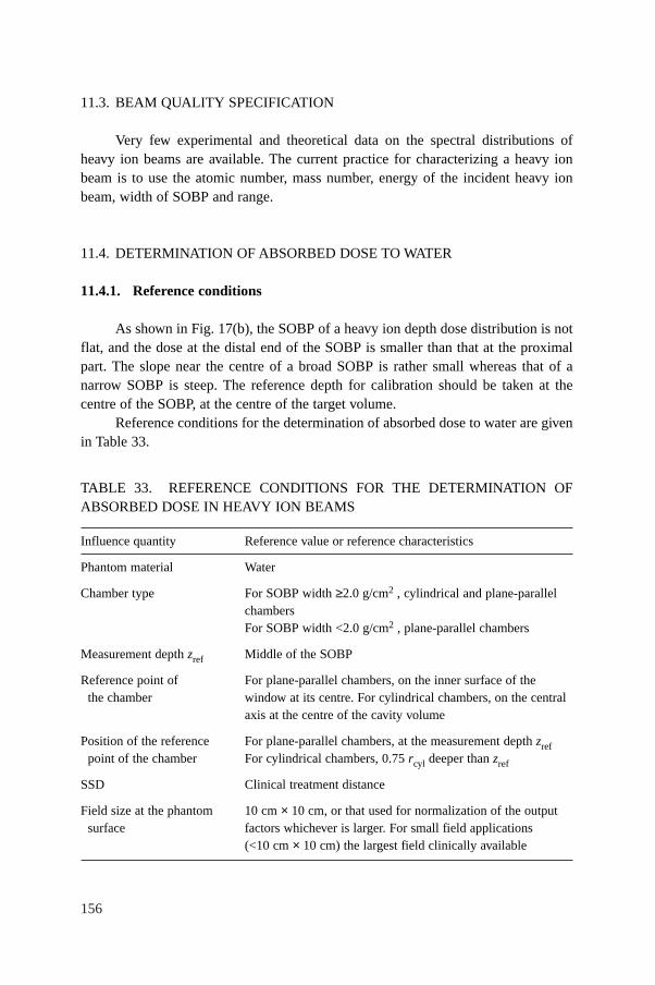
156
11.3. BEAM QUALITY SPECIFICATION
Very few experimental and theoretical data on the spectral distributions ofheavy ion beams are available. The current practice for characterizing a heavy ionbeam is to use the atomic number, mass number, energy of the incident heavy ionbeam, width of SOBP and range.
11.4. DETERMINATION OF ABSORBED DOSE TO WATER
11.4.1. Reference conditions
As shown in Fig. 17(b), the SOBP of a heavy ion depth dose distribution is notflat, and the dose at the distal end of the SOBP is smaller than that at the proximalpart. The slope near the centre of a broad SOBP is rather small whereas that of anarrow SOBP is steep. The reference depth for calibration should be taken at thecentre of the SOBP, at the centre of the target volume.
Reference conditions for the determination of absorbed dose to water are givenin Table 33.
TABLE 33. REFERENCE CONDITIONS FOR THE DETERMINATION OFABSORBED DOSE IN HEAVY ION BEAMS
Influence quantity Reference value or reference characteristics
Phantom material Water
Chamber type For SOBP width ≥2.0 g/cm2 , cylindrical and plane-parallel chambersFor SOBP width <2.0 g/cm2 , plane-parallel chambers
Measurement depth zref Middle of the SOBP
Reference point of For plane-parallel chambers, on the inner surface of the the chamber window at its centre. For cylindrical chambers, on the central
axis at the centre of the cavity volume
Position of the reference For plane-parallel chambers, at the measurement depth zrefpoint of the chamber For cylindrical chambers, 0.75 rcyl deeper than zref
SSD Clinical treatment distance
Field size at the phantom 10 cm × 10 cm, or that used for normalization of the outputsurface factors whichever is larger. For small field applications
(<10 cm × 10 cm) the largest field clinically available
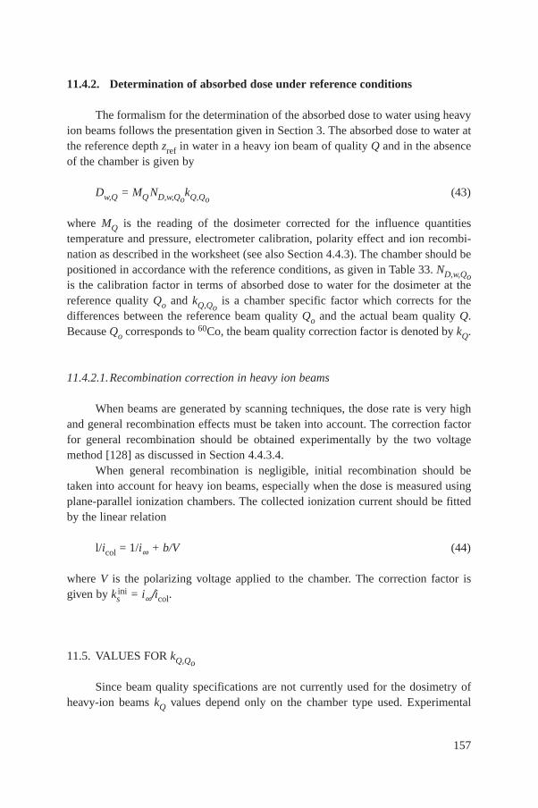
157
11.4.2. Determination of absorbed dose under reference conditions
The formalism for the determination of the absorbed dose to water using heavyion beams follows the presentation given in Section 3. The absorbed dose to water atthe reference depth zref in water in a heavy ion beam of quality Q and in the absenceof the chamber is given by
Dw,Q = MQ ND,w,QokQ,Qo
(43)
where MQ is the reading of the dosimeter corrected for the influence quantitiestemperature and pressure, electrometer calibration, polarity effect and ion recombi-nation as described in the worksheet (see also Section 4.4.3). The chamber should bepositioned in accordance with the reference conditions, as given in Table 33. ND,w,Qois the calibration factor in terms of absorbed dose to water for the dosimeter at thereference quality Qo and kQ,Qo
is a chamber specific factor which corrects for thedifferences between the reference beam quality Qo and the actual beam quality Q.Because Qo corresponds to 60Co, the beam quality correction factor is denoted by kQ.
11.4.2.1.Recombination correction in heavy ion beams
When beams are generated by scanning techniques, the dose rate is very highand general recombination effects must be taken into account. The correction factorfor general recombination should be obtained experimentally by the two voltagemethod [128] as discussed in Section 4.4.3.4.
When general recombination is negligible, initial recombination should betaken into account for heavy ion beams, especially when the dose is measured usingplane-parallel ionization chambers. The collected ionization current should be fittedby the linear relation
l/icol = 1/i∞ + b/V (44)
where V is the polarizing voltage applied to the chamber. The correction factor isgiven by ks
ini = i∞/icol.
11.5. VALUES FOR kQ,Qo
Since beam quality specifications are not currently used for the dosimetry ofheavy-ion beams kQ values depend only on the chamber type used. Experimental
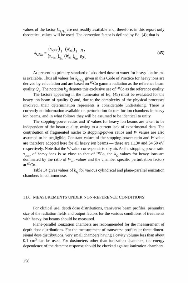
158
values of the factor kQ,Qoare not readily available and, therefore, in this report only
theoretical values will be used. The correction factor is defined by Eq. (4); that is
(45)
At present no primary standard of absorbed dose to water for heavy ion beamsis available. Thus all values for kQ,Qo
given in this Code of Practice for heavy ions arederived by calculation and are based on 60Co gamma radiation as the reference beamquality Qo. The notation kQ denotes this exclusive use of 60Co as the reference quality.
The factors appearing in the numerator of Eq. (45) must be evaluated for theheavy ion beam of quality Q and, due to the complexity of the physical processesinvolved, their determination represents a considerable undertaking. There iscurrently no information available on perturbation factors for ion chambers in heavyion beams, and in what follows they will be assumed to be identical to unity.
The stopping-power ratios and W values for heavy ion beams are taken to beindependent of the beam quality, owing to a current lack of experimental data. Thecontribution of fragmented nuclei to stopping-power ratios and W values are alsoassumed to be negligible. Constant values of the stopping-power ratio and W valueare therefore adopted here for all heavy ion beams — these are 1.130 and 34.50 eV,respectively. Note that the W value corresponds to dry air. As the stopping power ratiosw,air of heavy ions is so close to that of 60Co, the kQ values for heavy ions aredominated by the ratio of Wair values and the chamber specific perturbation factorsat 60Co.
Table 34 gives values of kQ for various cylindrical and plane-parallel ionizationchambers in common use.
11.6. MEASUREMENTS UNDER NON-REFERENCE CONDITIONS
For clinical use, depth dose distributions, transverse beam profiles, penumbrasize of the radiation fields and output factors for the various conditions of treatmentswith heavy ion beams should be measured.
Plane-parallel ionization chambers are recommended for the measurement ofdepth dose distributions. For the measurement of transverse profiles or three dimen-sional dose distributions, very small chambers having a cavity volume less than about0.1 cm3 can be used. For dosimeters other than ionization chambers, the energydependence of the detector response should be checked against ionization chambers.
( )( )
( )( )
air air
air air
w, Q Q QQ,Qo
w, QQ oQ oo
s W pk =
s W p
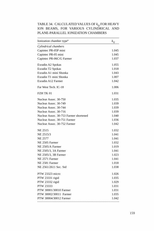
159
TABLE 34. CALCULATED VALUES OF kQ FOR HEAVYION BEAMS, FOR VARIOUS CYLINDRICAL ANDPLANE-PARALLEL IONIZATION CHAMBERS
Ionization chamber typea kQ
Cylindrical chambersCapintec PR-05P mini 1.045Capintec PR-05 mini 1.045Capintec PR-06C/G Farmer 1.037
Exradin A2 Spokas 1.055Exradin T2 Spokas 1.018Exradin A1 mini Shonka 1.043Exradin T1 mini Shonka 1.007Exradin A12 Farmer 1.042
Far West Tech. IC-18 1.006
FZH TK 01 1.031
Nuclear Assoc. 30-750 1.035Nuclear Assoc. 30-749 1.039Nuclear Assoc. 30-744 1.039Nuclear Assoc. 30-716 1.039Nuclear Assoc. 30-753 Farmer shortened 1.040Nuclear Assoc. 30-751 Farmer 1.036Nuclear Assoc. 30-752 Farmer 1.042
NE 2515 1.032NE 2515/3 1.041NE 2577 1.041NE 2505 Farmer 1.032NE 2505/A Farmer 1.019NE 2505/3, 3A Farmer 1.041NE 2505/3, 3B Farmer 1.023NE 2571 Farmer 1.041NE 2581 Farmer 1.018NE 2561/2611 Sec. Std 1.038
PTW 23323 micro 1.026PTW 23331 rigid 1.035PTW 23332 rigid 1.029PTW 23333 1.031PTW 30001/30010 Farmer 1.031PTW 30002/30011 Farmer 1.035PTW 30004/30012 Farmer 1.042
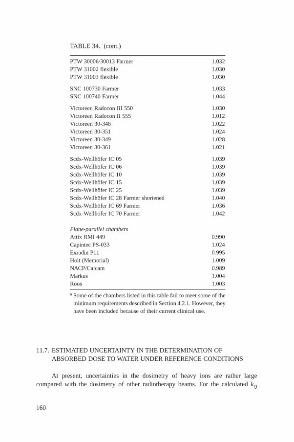
160
11.7. ESTIMATED UNCERTAINTY IN THE DETERMINATION OFABSORBED DOSE TO WATER UNDER REFERENCE CONDITIONS
At present, uncertainties in the dosimetry of heavy ions are rather largecompared with the dosimetry of other radiotherapy beams. For the calculated kQ
TABLE 34. (cont.)
PTW 30006/30013 Farmer 1.032PTW 31002 flexible 1.030PTW 31003 flexible 1.030
SNC 100730 Farmer 1.033SNC 100740 Farmer 1.044
Victoreen Radocon III 550 1.030Victoreen Radocon II 555 1.012Victoreen 30-348 1.022Victoreen 30-351 1.024Victoreen 30-349 1.028Victoreen 30-361 1.021
Scdx-Wellhöfer IC 05 1.039Scdx-Wellhöfer IC 06 1.039Scdx-Wellhöfer IC 10 1.039Scdx-Wellhöfer IC 15 1.039Scdx-Wellhöfer IC 25 1.039Scdx-Wellhöfer IC 28 Farmer shortened 1.040Scdx-Wellhöfer IC 69 Farmer 1.036Scdx-Wellhöfer IC 70 Farmer 1.042
Plane-parallel chambersAttix RMI 449 0.990Capintec PS-033 1.024Exradin P11 0.995Holt (Memorial) 1.009NACP/Calcam 0.989Markus 1.004Roos 1.003
a Some of the chambers listed in this table fail to meet some of theminimum requirements described in Section 4.2.1. However, theyhave been included because of their current clinical use.
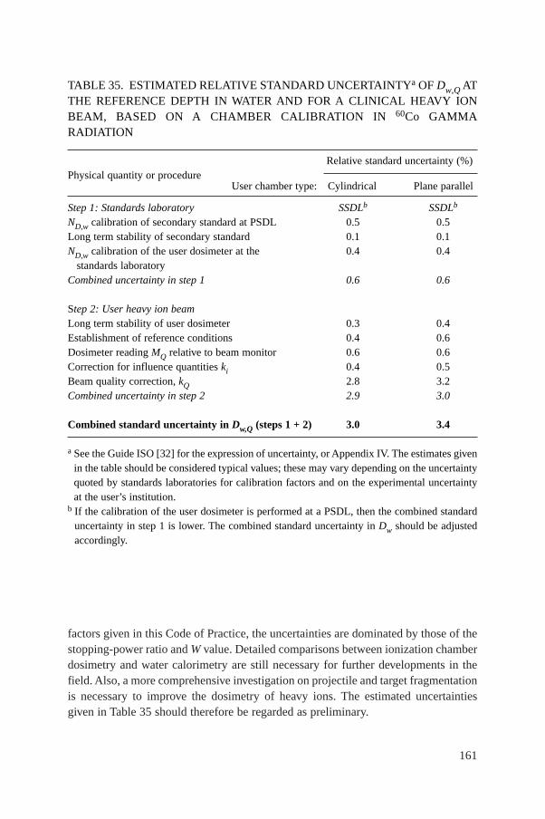
161
factors given in this Code of Practice, the uncertainties are dominated by those of thestopping-power ratio and W value. Detailed comparisons between ionization chamberdosimetry and water calorimetry are still necessary for further developments in thefield. Also, a more comprehensive investigation on projectile and target fragmentationis necessary to improve the dosimetry of heavy ions. The estimated uncertaintiesgiven in Table 35 should therefore be regarded as preliminary.
TABLE 35. ESTIMATED RELATIVE STANDARD UNCERTAINTYa OF Dw,Q ATTHE REFERENCE DEPTH IN WATER AND FOR A CLINICAL HEAVY IONBEAM, BASED ON A CHAMBER CALIBRATION IN 60Co GAMMARADIATION
Physical quantity or procedureRelative standard uncertainty (%)
User chamber type: Cylindrical Plane parallel
Step 1: Standards laboratory SSDLb SSDLb
ND,w calibration of secondary standard at PSDL 0.5 0.5Long term stability of secondary standard 0.1 0.1ND,w calibration of the user dosimeter at the 0.4 0.4
standards laboratoryCombined uncertainty in step 1 0.6 0.6
Step 2: User heavy ion beamLong term stability of user dosimeter 0.3 0.4Establishment of reference conditions 0.4 0.6Dosimeter reading MQ relative to beam monitor 0.6 0.6Correction for influence quantities ki 0.4 0.5Beam quality correction, kQ 2.8 3.2Combined uncertainty in step 2 2.9 3.0
Combined standard uncertainty in Dw,Q (steps 1 + 2) 3.0 3.4
a See the Guide ISO [32] for the expression of uncertainty, or Appendix IV. The estimates givenin the table should be considered typical values; these may vary depending on the uncertaintyquoted by standards laboratories for calibration factors and on the experimental uncertaintyat the user’s institution.
b If the calibration of the user dosimeter is performed at a PSDL, then the combined standarduncertainty in step 1 is lower. The combined standard uncertainty in Dw should be adjustedaccordingly.
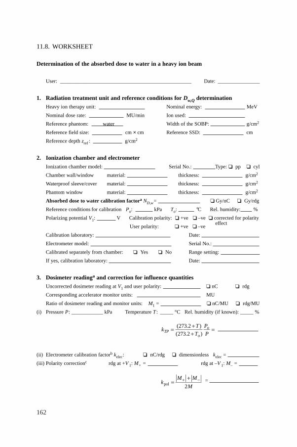
162
11.8. WORKSHEET
Determination of the absorbed dose to water in a heavy ion beam
User: __________________________________________________ Date: ________________
1. Radiation treatment unit and reference conditions for Dw,Q determination
Heavy ion therapy unit: Nominal energy: MeV
Nominal dose rate: MU/min Ion used:
Reference phantom: water Width of the SOBP: g/cm2
Reference field size: cm × cm Reference SSD: cm
Reference depth zref : g/cm2
2. Ionization chamber and electrometer
Ionization chamber model: Serial No.: Type: ❏ pp ❏ cyl
Chamber wall/window material: thickness: g/cm2
Waterproof sleeve/cover material: thickness: g/cm2
Phantom window material: thickness: g/cm2
Absorbed dose to water calibration factora ND,w= ❏ Gy/nC ❏ Gy/rdg
Reference conditions for calibration Po: kPa To: °C Rel. humidity: %
Polarizing potential V1: V Calibration polarity: ❏ +ve ❏ –ve ❏ corrected for polarity
User polarity: ❏ +ve ❏ –ve effect
Calibration laboratory: Date:
Electrometer model: Serial No.:
Calibrated separately from chamber: ❏ Yes ❏ No Range setting:
If yes, calibration laboratory: Date:
3. Dosimeter readinga and correction for influence quantities
Uncorrected dosimeter reading at V1 and user polarity: ❏ nC ❏ rdg
Corresponding accelerator monitor units: MU
Ratio of dosimeter reading and monitor units: M1 = ❏ nC/MU ❏ rdg/MU
(i) Pressure P: ____________ kPa Temperature T : _____ °C Rel. humidity (if known): _____ %
(ii) Electrometer calibration factorb kelec: ❏ nC/rdg ❏ dimensionless kelec =
(iii) Polarity correctionc rdg at +V 1: M+ = rdg at –V 1: M– =
= kM M
Mpol =++ -
2
kT
T
P
PTPo
o= ++
=( . )
( . )
273 2
273 2
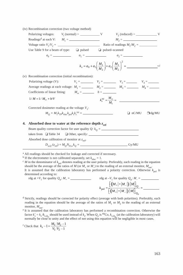
163
(iv) Recombination correction (two voltage method)
Polarizing voltages: Vl (normal) = ____________ V V2 (reduced) = _____________ V
Readingsd at each V: M1 = M2 =
Voltage ratio V1/V2 = __________________________ Ratio of readings M1/M2 = ___________
Use Table 9 for a beam of type: ❏ pulsed ❏ pulsed–scanned
a0 = a1 = a2 =
___________________e,f
(v) Recombination correction (initial recombination):
Polarizing voltage (V): V1 = V2 = V3 = V4 =
Average readings at each voltage: M1 = M2 = M3 = M4 =
Coefficients of linear fitting: M∞ = b =
Corrected dosimeter reading at the voltage V1:
MQ = M1kTPkeleckpolksksini = ❏ nC/MU ❒ rdg/MU
4. Absorbed dose to water at the reference depth zref
Beam quality correction factor for user quality Q: kQ =
taken from ❏ Table 34 ❏ Other, specify:
Absorbed dose calibration of monitor at zref,
Dw,Q (zref) = MQND,wkQ = Gy/MU
a All readings should be checked for leakage and corrected if necessary.b If the electrometer is not calibrated separately, set kelec = 1.c M in the denominator of kpol denotes reading at the user polarity. Preferably, each reading in the equation
should be the average of the ratios of M (or M+ or M–) to the reading of an external monitor, Mem. It is assumed that the calibration laboratory has performed a polarity correction. Otherwise kpol isdetermined according to:
rdg at +V1 for quality Qo: M+ = rdg at –V1 for quality Qo: M– =
d Strictly, readings should be corrected for polarity effect (average with both polarities). Preferably, eachreading in the equation should be the average of the ratios of M1 or M2 to the reading of an externalmonitor, Mem.
e It is assumed that the calibration laboratory has performed a recombination correction. Otherwise thefactor k′s = ks /ks,Qo
should be used instead of ks. When Qo is 60Co, ks,Qo(at the calibration laboratory) will
normally be close to unity and the effect of not using this equation will be negligible in most cases.
f Check that 1 2
1 2
11
1sM M –
k –V V –
ª
( )( )pol
+ –
+ –o
Q
Q
M + M Mk = = __________
M + M M
È ˘Î ˚È ˘Î ˚
inis
Mk
M1
•= =M M b/V1/ 1/ •= +
k a aM
Ma
M
Ms = +ÊËÁ
ˆ¯̃
+ÊËÁ
ˆ¯̃
=0 11
22
1
2
2
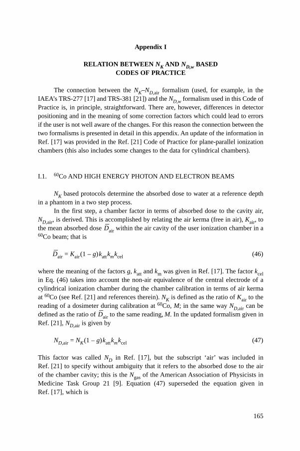
165
Appendix I
RELATION BETWEEN NK AND ND,w BASEDCODES OF PRACTICE
The connection between the NK–ND,air formalism (used, for example, in theIAEA’s TRS-277 [17] and TRS-381 [21]) and the ND,w formalism used in this Code ofPractice is, in principle, straightforward. There are, however, differences in detectorpositioning and in the meaning of some correction factors which could lead to errorsif the user is not well aware of the changes. For this reason the connection between thetwo formalisms is presented in detail in this appendix. An update of the information inRef. [17] was provided in the Ref. [21] Code of Practice for plane-parallel ionizationchambers (this also includes some changes to the data for cylindrical chambers).
I.1. 60Co AND HIGH ENERGY PHOTON AND ELECTRON BEAMS
NK based protocols determine the absorbed dose to water at a reference depthin a phantom in a two step process.
In the first step, a chamber factor in terms of absorbed dose to the cavity air,ND,air, is derived. This is accomplished by relating the air kerma (free in air), Kair, tothe mean absorbed dose
–Dair within the air cavity of the user ionization chamber in a
60Co beam; that is
–Dair = Kair(1 – g)kattkmkcel (46)
where the meaning of the factors g, katt and km was given in Ref. [17]. The factor kcelin Eq. (46) takes into account the non-air equivalence of the central electrode of acylindrical ionization chamber during the chamber calibration in terms of air kermaat 60Co (see Ref. [21] and references therein). NK is defined as the ratio of Kair to thereading of a dosimeter during calibration at 60Co, M; in the same way ND,air can bedefined as the ratio of
–Dair to the same reading, M. In the updated formalism given in
Ref. [21], ND,air is given by
ND,air = NK(1 – g)kattkmkcel (47)
This factor was called ND in Ref. [17], but the subscript ‘air’ was included inRef. [21] to specify without ambiguity that it refers to the absorbed dose to the airof the chamber cavity; this is the Ngas of the American Association of Physicists inMedicine Task Group 21 [9]. Equation (47) superseded the equation given inRef. [17], which is
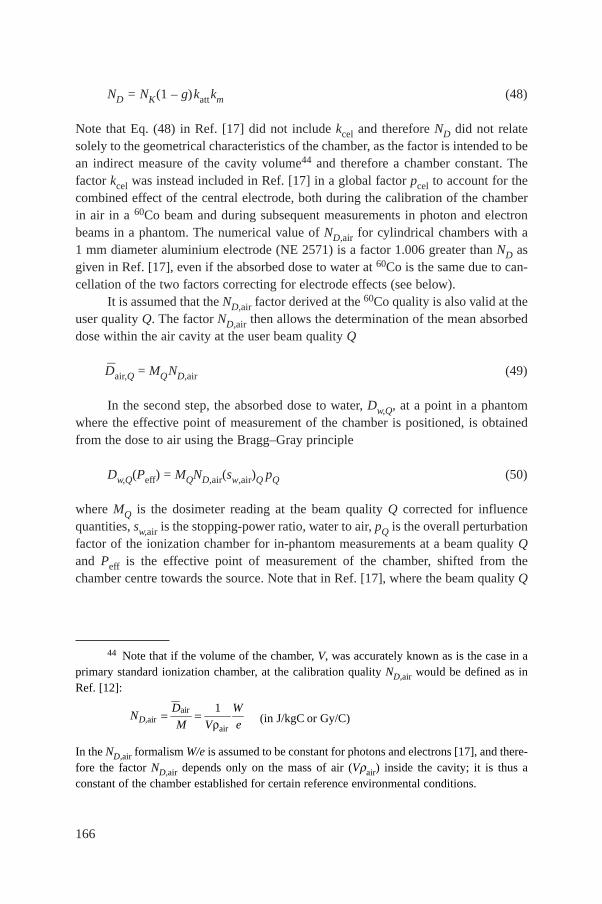
166
ND = NK(1 – g)kattkm (48)
Note that Eq. (48) in Ref. [17] did not include kcel and therefore ND did not relatesolely to the geometrical characteristics of the chamber, as the factor is intended to bean indirect measure of the cavity volume44 and therefore a chamber constant. Thefactor kcel was instead included in Ref. [17] in a global factor pcel to account for thecombined effect of the central electrode, both during the calibration of the chamberin air in a 60Co beam and during subsequent measurements in photon and electronbeams in a phantom. The numerical value of ND,air for cylindrical chambers with a1 mm diameter aluminium electrode (NE 2571) is a factor 1.006 greater than ND asgiven in Ref. [17], even if the absorbed dose to water at 60Co is the same due to can-cellation of the two factors correcting for electrode effects (see below).
It is assumed that the ND,air factor derived at the 60Co quality is also valid at theuser quality Q. The factor ND,air then allows the determination of the mean absorbeddose within the air cavity at the user beam quality Q
–Dair,Q = MQND,air (49)
In the second step, the absorbed dose to water, Dw,Q, at a point in a phantomwhere the effective point of measurement of the chamber is positioned, is obtainedfrom the dose to air using the Bragg–Gray principle
Dw,Q(Peff) = MQND,air(sw,air)Q pQ (50)
where MQ is the dosimeter reading at the beam quality Q corrected for influencequantities, sw,air is the stopping-power ratio, water to air, pQ is the overall perturbationfactor of the ionization chamber for in-phantom measurements at a beam quality Qand Peff is the effective point of measurement of the chamber, shifted from thechamber centre towards the source. Note that in Ref. [17], where the beam quality Q
44 Note that if the volume of the chamber, V, was accurately known as is the case in aprimary standard ionization chamber, at the calibration quality ND,air would be defined as inRef. [12]:
(in J/kgC or Gy/C)
In the ND,air formalism W/e is assumed to be constant for photons and electrons [17], and there-fore the factor ND,air depends only on the mass of air (Vrair) inside the cavity; it is thus aconstant of the chamber established for certain reference environmental conditions.
airair
air
1D,
D WN
M V e= =
r
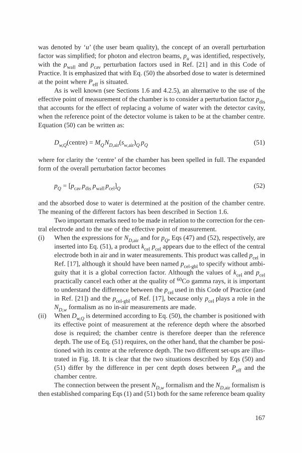
was denoted by ‘u’ (the user beam quality), the concept of an overall perturbationfactor was simplified; for photon and electron beams, pu was identified, respectively,with the pwall and pcav perturbation factors used in Ref. [21] and in this Code ofPractice. It is emphasized that with Eq. (50) the absorbed dose to water is determinedat the point where Peff is situated.
As is well known (see Sections 1.6 and 4.2.5), an alternative to the use of theeffective point of measurement of the chamber is to consider a perturbation factor pdisthat accounts for the effect of replacing a volume of water with the detector cavity,when the reference point of the detector volume is taken to be at the chamber centre.Equation (50) can be written as:
Dw,Q(centre) = MQND,air(sw,air)Q pQ (51)
where for clarity the ‘centre’ of the chamber has been spelled in full. The expandedform of the overall perturbation factor becomes
pQ = [pcav pdis pwall pcel]Q (52)
and the absorbed dose to water is determined at the position of the chamber centre.The meaning of the different factors has been described in Section 1.6.
Two important remarks need to be made in relation to the correction for the cen-tral electrode and to the use of the effective point of measurement.(i) When the expressions for ND,air and for pQ, Eqs (47) and (52), respectively, are
inserted into Eq. (51), a product kcel pcel appears due to the effect of the centralelectrode both in air and in water measurements. This product was called pcel inRef. [17], although it should have been named pcel-gbl to specify without ambi-guity that it is a global correction factor. Although the values of kcel and pcelpractically cancel each other at the quality of 60Co gamma rays, it is importantto understand the difference between the pcel used in this Code of Practice (andin Ref. [21]) and the pcel-gbl of Ref. [17], because only pcel plays a role in theND,w formalism as no in-air measurements are made.
(ii) When Dw,Q is determined according to Eq. (50), the chamber is positioned withits effective point of measurement at the reference depth where the absorbeddose is required; the chamber centre is therefore deeper than the referencedepth. The use of Eq. (51) requires, on the other hand, that the chamber be posi-tioned with its centre at the reference depth. The two different set-ups are illus-trated in Fig. 18. It is clear that the two situations described by Eqs (50) and(51) differ by the difference in per cent depth doses between Peff and thechamber centre.The connection between the present ND,w formalism and the ND,air formalism is
then established comparing Eqs (1) and (51) both for the same reference beam quality
167
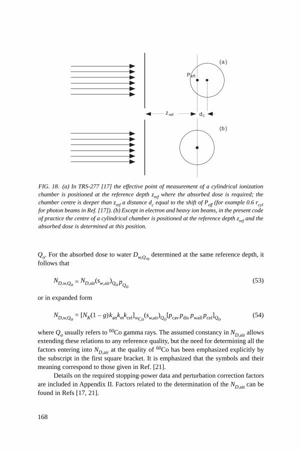
168
Qo. For the absorbed dose to water Dw,Q,odetermined at the same reference depth, it
follows that
ND,w,Qo = ND,air(sw,air)Qo pQo
(53)
or in expanded form
ND,w,Qo= [NK(1 – g)kattkmkcel]60Co
(sw,air)Qo[pcav pdis pwall pcel]Qo
(54)
where Qo usually refers to 60Co gamma rays. The assumed constancy in ND,air allowsextending these relations to any reference quality, but the need for determining all thefactors entering into ND,air at the quality of 60Co has been emphasized explicitly bythe subscript in the first square bracket. It is emphasized that the symbols and theirmeaning correspond to those given in Ref. [21].
Details on the required stopping-power data and perturbation correction factorsare included in Appendix II. Factors related to the determination of the ND,air can befound in Refs [17, 21].
FIG. 18. (a) In TRS-277 [17] the effective point of measurement of a cylindrical ionizationchamber is positioned at the reference depth zref where the absorbed dose is required; thechamber centre is deeper than zref a distance dc equal to the shift of Peff (for example 0.6 rcylfor photon beams in Ref. [17]). (b) Except in electron and heavy ion beams, in the present codeof practice the centre of a cylindrical chamber is positioned at the reference depth zref and theabsorbed dose is determined at this position.
Peff
z ref
(a )
(b )
dc
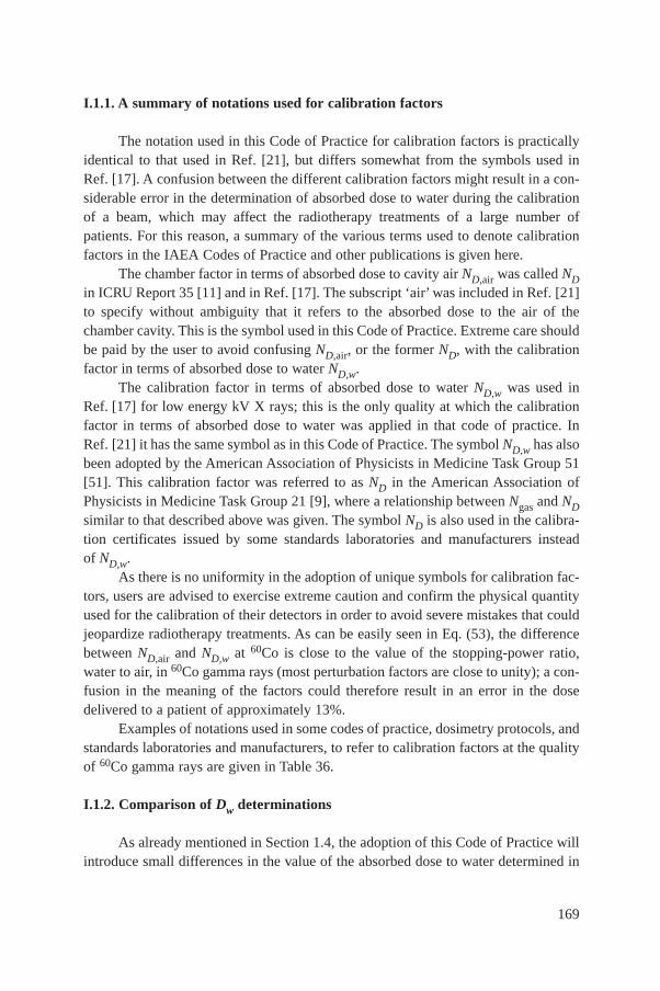
I.1.1. A summary of notations used for calibration factors
The notation used in this Code of Practice for calibration factors is practicallyidentical to that used in Ref. [21], but differs somewhat from the symbols used inRef. [17]. A confusion between the different calibration factors might result in a con-siderable error in the determination of absorbed dose to water during the calibrationof a beam, which may affect the radiotherapy treatments of a large number ofpatients. For this reason, a summary of the various terms used to denote calibrationfactors in the IAEA Codes of Practice and other publications is given here.
The chamber factor in terms of absorbed dose to cavity air ND,air was called NDin ICRU Report 35 [11] and in Ref. [17]. The subscript ‘air’ was included in Ref. [21]to specify without ambiguity that it refers to the absorbed dose to the air of thechamber cavity. This is the symbol used in this Code of Practice. Extreme care shouldbe paid by the user to avoid confusing ND,air, or the former ND, with the calibrationfactor in terms of absorbed dose to water ND,w.
The calibration factor in terms of absorbed dose to water ND,w was used inRef. [17] for low energy kV X rays; this is the only quality at which the calibrationfactor in terms of absorbed dose to water was applied in that code of practice. InRef. [21] it has the same symbol as in this Code of Practice. The symbol ND,w has alsobeen adopted by the American Association of Physicists in Medicine Task Group 51[51]. This calibration factor was referred to as ND in the American Association ofPhysicists in Medicine Task Group 21 [9], where a relationship between Ngas and NDsimilar to that described above was given. The symbol ND is also used in the calibra-tion certificates issued by some standards laboratories and manufacturers insteadof ND,w.
As there is no uniformity in the adoption of unique symbols for calibration fac-tors, users are advised to exercise extreme caution and confirm the physical quantityused for the calibration of their detectors in order to avoid severe mistakes that couldjeopardize radiotherapy treatments. As can be easily seen in Eq. (53), the differencebetween ND,air and ND,w at 60Co is close to the value of the stopping-power ratio,water to air, in 60Co gamma rays (most perturbation factors are close to unity); a con-fusion in the meaning of the factors could therefore result in an error in the dosedelivered to a patient of approximately 13%.
Examples of notations used in some codes of practice, dosimetry protocols, andstandards laboratories and manufacturers, to refer to calibration factors at the qualityof 60Co gamma rays are given in Table 36.
I.1.2. Comparison of Dw determinations
As already mentioned in Section 1.4, the adoption of this Code of Practice willintroduce small differences in the value of the absorbed dose to water determined in
169
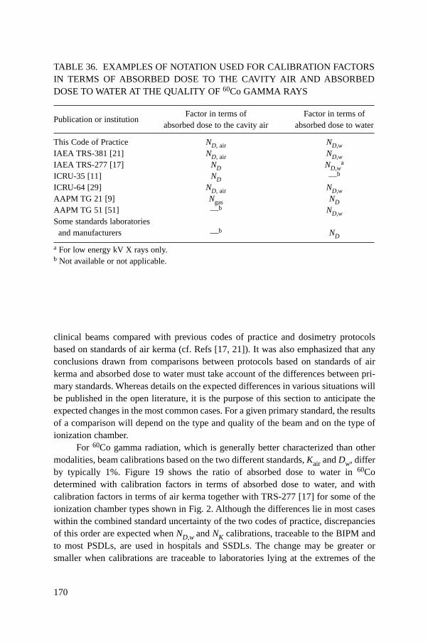
170
clinical beams compared with previous codes of practice and dosimetry protocolsbased on standards of air kerma (cf. Refs [17, 21]). It was also emphasized that anyconclusions drawn from comparisons between protocols based on standards of airkerma and absorbed dose to water must take account of the differences between pri-mary standards. Whereas details on the expected differences in various situations willbe published in the open literature, it is the purpose of this section to anticipate theexpected changes in the most common cases. For a given primary standard, the resultsof a comparison will depend on the type and quality of the beam and on the type ofionization chamber.
For 60Co gamma radiation, which is generally better characterized than othermodalities, beam calibrations based on the two different standards, Kair and Dw, differby typically 1%. Figure 19 shows the ratio of absorbed dose to water in 60Codetermined with calibration factors in terms of absorbed dose to water, and withcalibration factors in terms of air kerma together with TRS-277 [17] for some of theionization chamber types shown in Fig. 2. Although the differences lie in most caseswithin the combined standard uncertainty of the two codes of practice, discrepanciesof this order are expected when ND,w and NK calibrations, traceable to the BIPM andto most PSDLs, are used in hospitals and SSDLs. The change may be greater orsmaller when calibrations are traceable to laboratories lying at the extremes of the
TABLE 36. EXAMPLES OF NOTATION USED FOR CALIBRATION FACTORSIN TERMS OF ABSORBED DOSE TO THE CAVITY AIR AND ABSORBEDDOSE TO WATER AT THE QUALITY OF 60Co GAMMA RAYS
Publication or institutionFactor in terms of Factor in terms of
absorbed dose to the cavity air absorbed dose to water
This Code of Practice ND, air ND,wIAEA TRS-381 [21] ND, air ND,wIAEA TRS-277 [17] ND ND,w
a
ICRU-35 [11] ND —b
ICRU-64 [29] ND, air ND,wAAPM TG 21 [9] Ngas NDAAPM TG 51 [51] —b ND,wSome standards laboratories
and manufacturers —b ND
a For low energy kV X rays only.b Not available or not applicable.
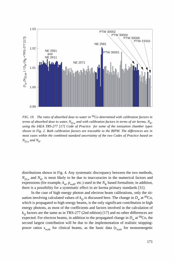
171
distributions shown in Fig. 4. Any systematic discrepancy between the two methods,ND,w and NK, is most likely to be due to inaccuracies in the numerical factors andexpressions (for example, km, pwall, etc.) used in the NK based formalism; in addition,there is a possibility for a systematic effect in air kerma primary standards [31].
In the case of high energy photon and electron beam calibrations, only the sit-uation involving calculated values of kQ is discussed here. The change in Dw at 60Co,which is propagated to high energy beams, is the only significant contribution in highenergy photons, as most of the coefficients and factors involved in the calculation ofkQ factors are the same as in TRS-277 (2nd edition) [17] and no other differences areexpected. For electron beams, in addition to the propagated change in Dw at 60Co, thesecond largest contribution will be due to the implementation of realistic stopping-power ratios sw,air for clinical beams, as the basic data (sw,air for monoenergetic
FIG. 19. The ratio of absorbed dose to water in 60Co determined with calibration factors interms of absorbed dose to water, ND,w and with calibration factors in terms of air kerma, NK,using the IAEA TRS-277 [17] Code of Practice for some of the ionization chamber typesshown in Fig. 2. Both calibration factors are traceable to the BIPM. The differences are inmost cases within the combined standard uncertainty of the two Codes of Practice based onND,w and NK.
DW
(N +
TR
S-2
77 [1
7])
) / D
w (
NK
D,w
0.99
1.00
1.01
1.02
1.03
NE 2561and
NE 2611
NE 2571
NE 2581
PTW 30001
PTW 30002
PTW 30006PTW 23333
PTW 30004
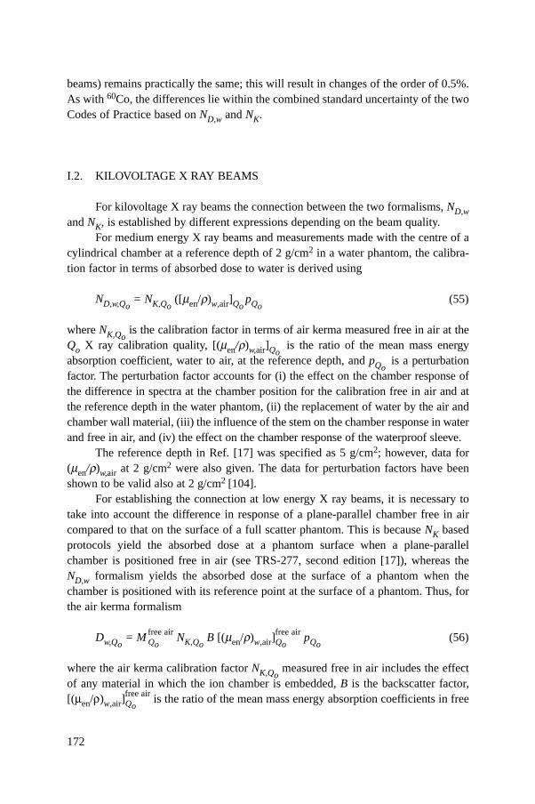
172
beams) remains practically the same; this will result in changes of the order of 0.5%.As with 60Co, the differences lie within the combined standard uncertainty of the twoCodes of Practice based on ND,w and NK.
I.2. KILOVOLTAGE X RAY BEAMS
For kilovoltage X ray beams the connection between the two formalisms, ND,wand NK, is established by different expressions depending on the beam quality.
For medium energy X ray beams and measurements made with the centre of acylindrical chamber at a reference depth of 2 g/cm2 in a water phantom, the calibra-tion factor in terms of absorbed dose to water is derived using
ND,w,Qo= NK,Qo
([men/r)w,air]QopQo
(55)
where NK,Qois the calibration factor in terms of air kerma measured free in air at the
Qo X ray calibration quality, [(men/r)w,air]Qois the ratio of the mean mass energy
absorption coefficient, water to air, at the reference depth, and pQois a perturbation
factor. The perturbation factor accounts for (i) the effect on the chamber response ofthe difference in spectra at the chamber position for the calibration free in air and atthe reference depth in the water phantom, (ii) the replacement of water by the air andchamber wall material, (iii) the influence of the stem on the chamber response in waterand free in air, and (iv) the effect on the chamber response of the waterproof sleeve.
The reference depth in Ref. [17] was specified as 5 g/cm2; however, data for(men/r)w,air at 2 g/cm2 were also given. The data for perturbation factors have beenshown to be valid also at 2 g/cm2 [104].
For establishing the connection at low energy X ray beams, it is necessary totake into account the difference in response of a plane-parallel chamber free in aircompared to that on the surface of a full scatter phantom. This is because NK basedprotocols yield the absorbed dose at a phantom surface when a plane-parallelchamber is positioned free in air (see TRS-277, second edition [17]), whereas theND,w formalism yields the absorbed dose at the surface of a phantom when thechamber is positioned with its reference point at the surface of a phantom. Thus, forthe air kerma formalism
Dw,Qo= M Qo
free air NK,QoB [(men/r)w,air]Qo
free air pQo(56)
where the air kerma calibration factor NK,Qomeasured free in air includes the effect
of any material in which the ion chamber is embedded, B is the backscatter factor,[(men/r)w,air]Qo
free air is the ratio of the mean mass energy absorption coefficients in free
air, and pQois assumed to be unity for the plane-parallel chambers used. For a
formalism based on calibration factors in terms of absorbed dose to water
Dw,Qo= M Qo
surface ND,w,Qo(57)
From Eqs (56) and (57) it follows that
(58)
Data for the various factors in Eqs (55) to (58) have been given in the second editionof Ref. [17] or may be found in other current dosimetry protocols and codes of prac-tice [17, 96, 97]. The relationships given in this section allow both the comparison ofthis Code of Practice with protocols based on calibration factors in terms of air kerma,and also the use of this Code of Practice by means of ND,w,Qo
calibration factorsderived from standards of air kerma. A comparison of this Code of Practice with anair kerma based protocol is effectively a verification of the factors [(men /r)w,air]Qo
pQoand B. Because there has been some doubt, particularly in the last two, such compar-isons will be valuable.
freeair
freeairsurface en ,air[( / ) ]Qo
D,w,Q K,Q w QQo o ooQo
MN N B p
M= m r
173
Appendix II
CALCULATION OF kQ,QoAND ITS UNCERTAINTY
II.1. GENERAL
The beam quality correction factor kQ,Qois defined by Eq. (3). In this Code of
Practice, values for kQ,Qomeasured for a particular chamber should be used when
available. However, in most cases such data will not be available and calculatedvalues must be used. Under conditions where the Bragg–Gray cavity theory is valid,values for kQ,Qo
may be calculated using Eq. (4):
(59)
In photon and electron beams, the basic monoenergetic data used for electron stop-ping powers are those given in ICRU Report 37 [64], with the density effect modeldue to Sternheimer. For proton and heavy ion beams the basic monoenergetic dataused for stopping powers are those given in ICRU Report 49 [118].
The value for (Wair /e) of 33.97 J/C [129–131] is used in this Code of Practice for all photon and electron beams. However, in view of some evidence of apossible variation in Wair between 60Co and high energy photon and electronbeams [55], a component of uncertainty is included where appropriate. The value forWair used for proton and heavy ion beams is discussed in the relevant sections of thisappendix.
In the absence of a consistent data set for perturbation factors, these arenecessarily treated in a less coherent way. Certain components are derived fromexperiment, others by Monte Carlo or other calculations, and in some instances whereno reliable estimate can be made they are taken to be unity and an appropriate uncer-tainty included.
The values for sw,air, Wair and p for 60Co, high energy photons, electrons,protons and heavy ions, and the resulting kQ,Qo
factors and their uncertainties, arediscussed in separate sections below. In estimating the uncertainty of kQ,Qo
factors,correlations between the various parameters are taken into account in an approxi-mate manner. For low and medium energy X rays the Bragg–Gray cavity theory isnot valid and so no calculated values for kQ,Qo
are given in this Code of Practice forthese radiation types.
In this appendix the term ‘uncertainty’ refers to the relative standard uncertaintyexpressed as a percentage.
( )( )
( )( )
air air
air air
Q Q QQ,Qo
QQ oQ oo
w,
w,
s W
s W
pk
p=
174
II.2. 60Co GAMMA RADIATION
As noted previously, when the reference quality Qo is 60Co, the symbol forkQ,Qo
is simplified to kQ. The factors sw,air, Wair and pQ for 60Co appear in the denom-inator of kQ for all radiation types and the values used are presented here.
II.2.1. Value for sw,air in 60Co
The value sw,air = 1.133 for 60Co was calculated by Andreo et al. [80] using themonoenergetic electron stopping-power data tabulated in Ref. [64] with the densityeffect correction due to Sternheimer. Uncertainties associated with the meanexcitation energies (I values) and density effect corrections give rise to a standarduncertainty of 0.5%, which does not include the basic uncertainty inherent in the stop-ping-power model. In addition, as a consequence of spectral differences between60Co beams, the uncertainty in assigning a stopping-power ratio to a particular 60Cobeam is estimated to be 0.1%.
II.2.2. Value for Wair in 60Co
Wair is the mean energy expended in air per ion pair formed, more usuallyexpressed in the form Wair/e. The value for Wair/e in 60Co, for dry air, is taken to be33.97 J/C [129–131]. The uncertainty of this value was estimated by Niatel et al.[129] to be 0.2%.
II.2.3. Values for pQ in 60Co
The overall perturbation factor includes all departures from the behaviour of anideal Bragg–Gray detector. In general, the contributing effects are small so that theindividual perturbation factors pi have values close to unity and can be treated inde-pendently. For cylindrical chamber types, the overall perturbation factor is obtainedas the product
pQ = pcav pdis pwall pcel (60)
The component perturbation factors pcav, pdis, pwall and pcel are defined in Section 1.6.For plane-parallel chamber types, pdis and pcel are omitted.
II.2.3.1. Values for pcav in 60Co
The cavity correction pcav corrects for the perturbation of the electron fluencedue to scattering differences between the air cavity and the medium. Since transient
175
176
electronic equilibrium exists in 60Co at zref (5 g/cm2 in water), the value for pcav istaken to be unity (for both cylindrical and plane-parallel chamber types). The uncer-tainty associated with this assumption is negligible (<0.1%).
II.2.3.2. Values for pdis in 60Co
The displacement correction accounts for the fact that a cylindrical chambercavity with its centre at zref samples the electron fluence at a point which is closer tothe radiation source than zref. The correction depends on the inner radius of the cavity,rcyl. Values derived from the measurements of Johansson et al. [132] have been used:
pdis = 1 – 0.004 rcyl (61)
where rcyl is in mm. The uncertainty of pdis was estimated by Johansson et al. [132]to be 0.3%. Plane-parallel chamber types are positioned with the front of the air cavityat zref and it is assumed that no displacement correction is necessary; the uncertaintyin this assumption is estimated to be 0.2%.
II.2.3.3. Values for pwall in 60Co
The factor pwall accounts for differences in the photon mass energy absorptioncoefficients and electron stopping powers of the chamber wall material and themedium. For cylindrical chamber types, a thin plastic waterproofing sleeve is nor-mally used to protect the chamber. The formulation developed by Almond andSvensson [133] and modified independently by Gillin et al. [134] and Hanson andDominguez-Tinoco [135] is used in this Code of Practice for the evaluation of pwall,which includes the effect of the sleeve
αswall,air(µen/ρ)w,wall + τ ssleeve,air (µen/ρ)w,sleeve+(1–α–τ)sw,airpwall = ————————————————————————— (62)
sw,air
The values used assume a PMMA sleeve of thickness 0.5 mm. The values usedfor smed,air are those evaluated by Andreo et al. [80] using the electron stopping-powerdata with Sternheimer density effect corrections tabulated in Ref. [64]. The ratios ofphoton mass energy absorption coefficients are taken from Cunningham (seeRef. [17]). The values for a and t are determined according to the expressions givenin Ref. [21]; that is
a(tw) = 1– e–11.88tw (63)
and
t (ts) = e–11.88tw(1 – e–11.88ts) (64)
where tw and ts are, respectively, the thickness of the wall and the sleeve (in g/cm2).These are based on the experimental data of Lempert et al. [136] for which no uncer-tainty estimates were given. Andreo et al. [80] compared the calculated ratios of pwallfor some materials with the experimental data of Johansson et al. [132] and foundagreement within 0.4%. Based on this, a combined standard uncertainty of 0.5% isestimated for pwall.
This estimate applies also to plastic walled chambers having a thin conductivelayer or coating of graphite (‘dag’). The effect of this coating on pwall is difficult toestimate and both Monte Carlo calculations and experiments have so far failed toprovide a satisfactory explanation of the underlying phenomena (see Ref. [137]). Inaddition, manufacturers do not generally provide information on the exact thicknessof the coating, an exception being PTW (see footnote e in Table 3). An alternativecalculation of pwall for the PTW 30001 and 30010 chamber types has been madeusing Eq. (62), taking the 0.15 mm graphite coating (of density r = 0.82 g/cm3) to bethe chamber wall and including the PMMA section of the wall as part of the water-proof sleeve. This results in a value for pwall which is approximately 0.3% lower for60Co gamma rays. However, approximately the same decrease is obtained for pwall forhigh energy photons, so that the effect of the graphite coating largely cancels in theratio of pwall values entering into the calculation of kQ. These agree within 0.1% withthe kQ values obtained for this type of chamber under the assumption that the entirewall is made of PMMA (it is these latter values which are adopted for high energyphotons in this Code of Practice). The contribution to the uncertainty of pwall arisingfrom this effect is considered to be negligible (<0.1%).
For plane-parallel chamber types, pwall is problematic and variations of up to3% between chambers of the same type have been reported [138]. It is for this reasonthat the cross-calibration method is included in Section 7. Nevertheless, values havebeen derived by a combination of measurement and calculation. Those given in Ref.[21] for a number of chamber types have been used. In addition, values for the Attix,Exradin and Holt chamber types have been taken from the calculations of Rogers[139]. By assuming that the 3% variations represent the 67% (k = 1) confidenceinterval of a normal distribution, the standard uncertainty is estimated to be 1.5%.
II.2.3.4. Values for pcel in 60Co
For cylindrical chamber types, pcel corrects for the lack of air equivalence of thecentral electrode. The correction for this effect is negligible for plastic and graphitecentral electrodes, as shown by the Monte Carlo calculations of Ma and Nahum [140]
177
178
and the experimental determinations of Palm and Mattsson [141]. Both groups alsoshowed that an aluminium central electrode of diameter 1 mm, as used in manyFarmer type chambers, increases the chamber response by around 0.7% at the refer-ence depth in 60Co. These findings were in good agreement with the increasedresponse previously measured by Mattsson [142]. Thus a value for pcel of 0.993 hasbeen used here for chambers with an aluminium central electrode of 1 mm diameter.The uncertainty of the most recent measurements is 0.2% [141]. It is important tonote that this value agrees with that used in Ref. [17], in which a value for pcel-gbl ofunity was assumed for all cylindrical chamber types having a 1 mm diameter alu-minium electrode as a result of the cancellation between the effect in air and in watermeasurements (see Appendix I).
II.2.4. Summary of values and uncertainties in 60Co
Table 37 lists the values used for the factors pdis, pwall and pcel and for theproduct sw,air pQ for the cylindrical chamber types listed in Table 3. The uncertaintyestimates as discussed above are summarized in Table 38.
II.3. HIGH ENERGY PHOTON BEAMS
The individual parameters entering in the numerator of Eq. (59) for high energyphoton beams are discussed below. In estimating the uncertainties, correlationsbetween the values for these parameters in 60Co and in the high energy photon beamsare taken into account, since it is only ratios which enter into the kQ factor.
II.3.1. Values for sw,air in high energy photon beams
The Spencer–Attix stopping-power ratios sw,air are taken from the calculationsof Andreo [143, 144]. These calculations were performed by using the electron stop-ping-power data tabulated in Ref. [64]. In estimating the uncertainty of sw,air relativeto the 60Co value, correlations are not large because the main effects are those arisingfrom the uncertainty of the I value for water, which is important for 60Co but not forhigh energies, and the density effect model used for water, which is important only athigher energies. A value of 0.5% has been estimated. The uncertainty in assigningstopping-power ratios to a particular user beam quality is estimated to be 0.3%.
II.3.2. Value for Wair in high energy photon beams
The value for Wair normally used for high energy photon beams is the same asthat used for 60Co, and this trend is followed in this Code of Practice. However, there
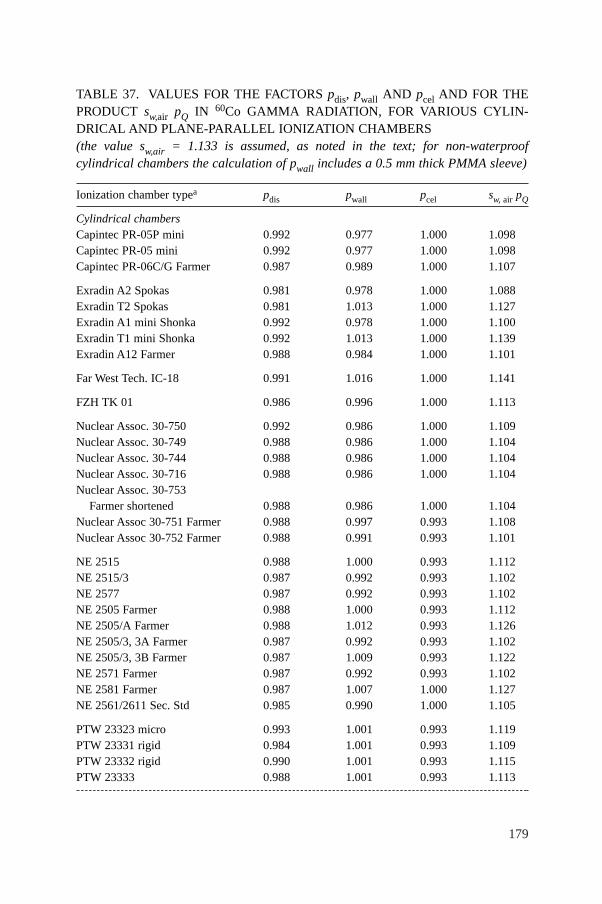
179
TABLE 37. VALUES FOR THE FACTORS pdis, pwall AND pcel AND FOR THEPRODUCT sw,air pQ IN 60Co GAMMA RADIATION, FOR VARIOUS CYLIN-DRICAL AND PLANE-PARALLEL IONIZATION CHAMBERS (the value sw,air = 1.133 is assumed, as noted in the text; for non-waterproofcylindrical chambers the calculation of pwall includes a 0.5 mm thick PMMA sleeve)
Ionization chamber typea pdis pwall pcel sw, air pQ
Cylindrical chambersCapintec PR-05P mini 0.992 0.977 1.000 1.098Capintec PR-05 mini 0.992 0.977 1.000 1.098Capintec PR-06C/G Farmer 0.987 0.989 1.000 1.107
Exradin A2 Spokas 0.981 0.978 1.000 1.088Exradin T2 Spokas 0.981 1.013 1.000 1.127Exradin A1 mini Shonka 0.992 0.978 1.000 1.100Exradin T1 mini Shonka 0.992 1.013 1.000 1.139Exradin A12 Farmer 0.988 0.984 1.000 1.101
Far West Tech. IC-18 0.991 1.016 1.000 1.141
FZH TK 01 0.986 0.996 1.000 1.113
Nuclear Assoc. 30-750 0.992 0.986 1.000 1.109Nuclear Assoc. 30-749 0.988 0.986 1.000 1.104Nuclear Assoc. 30-744 0.988 0.986 1.000 1.104Nuclear Assoc. 30-716 0.988 0.986 1.000 1.104Nuclear Assoc. 30-753
Farmer shortened 0.988 0.986 1.000 1.104Nuclear Assoc 30-751 Farmer 0.988 0.997 0.993 1.108Nuclear Assoc 30-752 Farmer 0.988 0.991 0.993 1.101
NE 2515 0.988 1.000 0.993 1.112NE 2515/3 0.987 0.992 0.993 1.102NE 2577 0.987 0.992 0.993 1.102NE 2505 Farmer 0.988 1.000 0.993 1.112NE 2505/A Farmer 0.988 1.012 0.993 1.126NE 2505/3, 3A Farmer 0.987 0.992 0.993 1.102NE 2505/3, 3B Farmer 0.987 1.009 0.993 1.122NE 2571 Farmer 0.987 0.992 0.993 1.102NE 2581 Farmer 0.987 1.007 1.000 1.127NE 2561/2611 Sec. Std 0.985 0.990 1.000 1.105
PTW 23323 micro 0.993 1.001 0.993 1.119PTW 23331 rigid 0.984 1.001 0.993 1.109PTW 23332 rigid 0.990 1.001 0.993 1.115PTW 23333 0.988 1.001 0.993 1.113
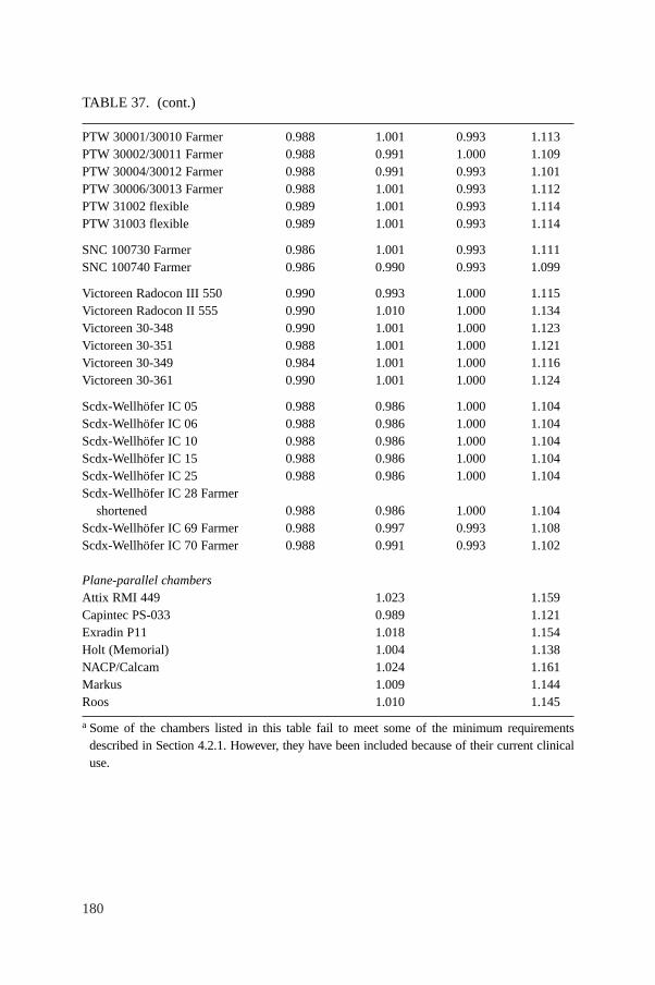
180
TABLE 37. (cont.)
PTW 30001/30010 Farmer 0.988 1.001 0.993 1.113PTW 30002/30011 Farmer 0.988 0.991 1.000 1.109PTW 30004/30012 Farmer 0.988 0.991 0.993 1.101PTW 30006/30013 Farmer 0.988 1.001 0.993 1.112PTW 31002 flexible 0.989 1.001 0.993 1.114PTW 31003 flexible 0.989 1.001 0.993 1.114
SNC 100730 Farmer 0.986 1.001 0.993 1.111SNC 100740 Farmer 0.986 0.990 0.993 1.099
Victoreen Radocon III 550 0.990 0.993 1.000 1.115Victoreen Radocon II 555 0.990 1.010 1.000 1.134Victoreen 30-348 0.990 1.001 1.000 1.123Victoreen 30-351 0.988 1.001 1.000 1.121Victoreen 30-349 0.984 1.001 1.000 1.116Victoreen 30-361 0.990 1.001 1.000 1.124
Scdx-Wellhöfer IC 05 0.988 0.986 1.000 1.104Scdx-Wellhöfer IC 06 0.988 0.986 1.000 1.104Scdx-Wellhöfer IC 10 0.988 0.986 1.000 1.104Scdx-Wellhöfer IC 15 0.988 0.986 1.000 1.104Scdx-Wellhöfer IC 25 0.988 0.986 1.000 1.104Scdx-Wellhöfer IC 28 Farmer
shortened 0.988 0.986 1.000 1.104Scdx-Wellhöfer IC 69 Farmer 0.988 0.997 0.993 1.108Scdx-Wellhöfer IC 70 Farmer 0.988 0.991 0.993 1.102
Plane-parallel chambersAttix RMI 449 1.023 1.159Capintec PS-033 0.989 1.121Exradin P11 1.018 1.154Holt (Memorial) 1.004 1.138NACP/Calcam 1.024 1.161Markus 1.009 1.144Roos 1.010 1.145
a Some of the chambers listed in this table fail to meet some of the minimum requirementsdescribed in Section 4.2.1. However, they have been included because of their current clinicaluse.
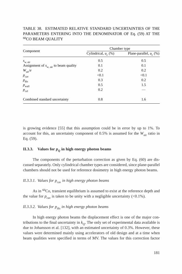
181
is growing evidence [55] that this assumption could be in error by up to 1%. Toaccount for this, an uncertainty component of 0.5% is assumed for the Wair ratio inEq. (59).
II.3.3. Values for pQ in high energy photon beams
The components of the perturbation correction as given by Eq. (60) are dis-cussed separately. Only cylindrical chamber types are considered, since plane-parallelchambers should not be used for reference dosimetry in high energy photon beams.
II.3.3.1. Values for pcav in high energy photon beams
As in 60Co, transient equilibrium is assumed to exist at the reference depth andthe value for pcav is taken to be unity with a negligible uncertainty (<0.1%).
II.3.3.2. Values for pdis in high energy photon beams
In high energy photon beams the displacement effect is one of the major con-tributions to the final uncertainty in kQ. The only set of experimental data available isdue to Johansson et al. [132], with an estimated uncertainty of 0.3%. However, thesevalues were determined mainly using accelerators of old design and at a time whenbeam qualities were specified in terms of MV. The values for this correction factor
TABLE 38. ESTIMATED RELATIVE STANDARD UNCERTAINTIES OF THEPARAMETERS ENTERING INTO THE DENOMINATOR OF Eq. (59) AT THE60CO BEAM QUALITY
ComponentChamber type
Cylindrical, uc (%) Plane-parallel, uc (%)
sw, air 0.5 0.5Assignment of sw, air to beam quality 0.1 0.1Wair/e 0.2 0.2pcav <0.1 <0.1pdis 0.3 0.2pwall 0.5 1.5pcel 0.2 —
Combined standard uncertainty 0.8 1.6
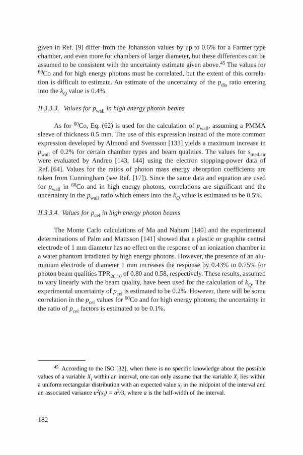
182
given in Ref. [9] differ from the Johansson values by up to 0.6% for a Farmer typechamber, and even more for chambers of larger diameter, but these differences can beassumed to be consistent with the uncertainty estimate given above.45 The values for60Co and for high energy photons must be correlated, but the extent of this correla-tion is difficult to estimate. An estimate of the uncertainty of the pdis ratio enteringinto the kQ value is 0.4%.
II.3.3.3. Values for pwall in high energy photon beams
As for 60Co, Eq. (62) is used for the calculation of pwall, assuming a PMMAsleeve of thickness 0.5 mm. The use of this expression instead of the more commonexpression developed by Almond and Svensson [133] yields a maximum increase inpwall of 0.2% for certain chamber types and beam qualities. The values for smed,airwere evaluated by Andreo [143, 144] using the electron stopping-power data ofRef. [64]. Values for the ratios of photon mass energy absorption coefficients aretaken from Cunningham (see Ref. [17]). Since the same data and equation are usedfor pwall in 60Co and in high energy photons, correlations are significant and theuncertainty in the pwall ratio which enters into the kQ value is estimated to be 0.5%.
II.3.3.4. Values for pcel in high energy photon beams
The Monte Carlo calculations of Ma and Nahum [140] and the experimentaldeterminations of Palm and Mattsson [141] showed that a plastic or graphite centralelectrode of 1 mm diameter has no effect on the response of an ionization chamber ina water phantom irradiated by high energy photons. However, the presence of an alu-minium electrode of diameter 1 mm increases the response by 0.43% to 0.75% forphoton beam qualities TPR20,10 of 0.80 and 0.58, respectively. These results, assumedto vary linearly with the beam quality, have been used for the calculation of kQ. Theexperimental uncertainty of pcel is estimated to be 0.2%. However, there will be somecorrelation in the pcel values for 60Co and for high energy photons; the uncertainty inthe ratio of pcel factors is estimated to be 0.1%.
45 According to the ISO [32], when there is no specific knowledge about the possiblevalues of a variable Xi within an interval, one can only assume that the variable Xi lies withina uniform rectangular distribution with an expected value xi in the midpoint of the interval andan associated variance u2(xi) = a2/3, where a is the half-width of the interval.
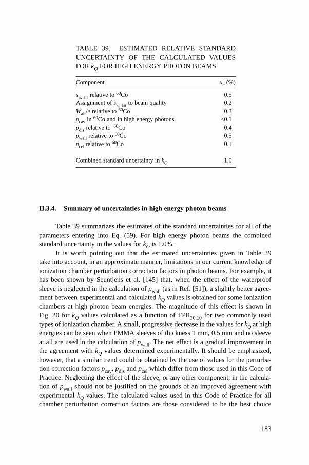
183
II.3.4. Summary of uncertainties in high energy photon beams
Table 39 summarizes the estimates of the standard uncertainties for all of theparameters entering into Eq. (59). For high energy photon beams the combinedstandard uncertainty in the values for kQ is 1.0%.
It is worth pointing out that the estimated uncertainties given in Table 39take into account, in an approximate manner, limitations in our current knowledge ofionization chamber perturbation correction factors in photon beams. For example, ithas been shown by Seuntjens et al. [145] that, when the effect of the waterproofsleeve is neglected in the calculation of pwall (as in Ref. [51]), a slightly better agree-ment between experimental and calculated kQ values is obtained for some ionizationchambers at high photon beam energies. The magnitude of this effect is shown inFig. 20 for kQ values calculated as a function of TPR20,10 for two commonly usedtypes of ionization chamber. A small, progressive decrease in the values for kQ at highenergies can be seen when PMMA sleeves of thickness 1 mm, 0.5 mm and no sleeveat all are used in the calculation of pwall. The net effect is a gradual improvement inthe agreement with kQ values determined experimentally. It should be emphasized,however, that a similar trend could be obtained by the use of values for the perturba-tion correction factors pcav, pdis and pcel which differ from those used in this Code ofPractice. Neglecting the effect of the sleeve, or any other component, in the calcula-tion of pwall should not be justified on the grounds of an improved agreement withexperimental kQ values. The calculated values used in this Code of Practice for allchamber perturbation correction factors are those considered to be the best choice
TABLE 39. ESTIMATED RELATIVE STANDARDUNCERTAINTY OF THE CALCULATED VALUESFOR kQ FOR HIGH ENERGY PHOTON BEAMS
Component uc (%)
sw, air relative to 60Co 0.5Assignment of sw, air to beam quality 0.2Wair/e relative to 60Co 0.3pcav in 60Co and in high energy photons <0.1pdis relative to 60Co 0.4pwall relative to 60Co 0.5pcel relative to 60Co 0.1
Combined standard uncertainty in kQ 1.0

184
FIG. 20. Comparison of experimental and calculated kQ values for high energy photon beams,where the influence of PMMA waterproof sleeves of different thicknesses in the calculation ofthe pwall correction factors is shown for the chamber types (a) NE 2561/2611 and (b) NE 2571.The experimental values (filled circles) were measured at the NPL , for which an uncertaintyof 0.7% has been estimated (see footnote c in Table 15). The sleeve thicknesses are 1 mm(dotted lines, inverted triangles), 0.5 mm (solid lines, upright triangles) and no sleeve (dashedlines, squares).
Photon beam quality, Q (TPR 20,10)
kQ
0.55 0.60 0.65 0.70 0.75 0.80 0.850.95
0.96
0.97
0.98
0.99
1.00
1.01
(b)
NE 2571
Photon beam quality, Q (TPR 20,10)
kQ
0.55 0.60 0.65 0.70 0.75 0.80 0.850.95
0.96
0.97
0.98
0.99
1.00
1.01
(a)
NE 2561/2611
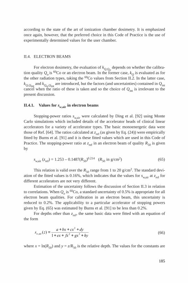
according to the state of the art of ionization chamber dosimetry. It is emphasizedonce again, however, that the preferred choice in this Code of Practice is the use ofexperimentally determined values for the user chamber.
II.4. ELECTRON BEAMS
For electron dosimetry, the evaluation of kQ,Qodepends on whether the calibra-
tion quality Qo is 60Co or an electron beam. In the former case, kQ is evaluated as forthe other radiation types, taking the 60Co values from Section II.2. In the latter case,kQ,Qint
and kQo,Qintare introduced, but the factors (and uncertainties) contained in Qint
cancel when the ratio of these is taken and so the choice of Qint is irrelevant to thepresent discussion.
II.4.1. Values for sw,air in electron beams
Stopping-power ratios sw,air were calculated by Ding et al. [92] using MonteCarlo simulations which included details of the accelerator heads of clinical linearaccelerators for a variety of accelerator types. The basic monoenergetic data werethose of Ref. [64]. The ratios calculated at zref (as given by Eq. (24)) were empiricallyfitted by Burns et al. [91] and it is these fitted values which are used in this Code ofPractice. The stopping-power ratio at zref in an electron beam of quality R50 is givenby
sw,air (zref) = 1.253 – 0.1487(R50)0.214 (R50 in g/cm2) (65)
This relation is valid over the R50 range from 1 to 20 g/cm2. The standard devi-ation of the fitted values is 0.16%, which indicates that the values for sw,air at zref fordifferent accelerators are not very different.
Estimation of the uncertainty follows the discussion of Section II.3 in relationto correlations. When Qo is 60Co, a standard uncertainty of 0.5% is appropriate for allelectron beam qualities. For calibration in an electron beam, this uncertainty isreduced to 0.2%. The applicability to a particular accelerator of stopping powersgiven by Eq. (65) was estimated by Burns et al. [91] to be less than 0.2%.
For depths other than zref, the same basic data were fitted with an equation ofthe form
(66)
where x = ln(R50) and y = z/R50 is the relative depth. The values for the constants are
s za bx cx dy
ex fx gx hyw, ( )air = + + +
+ + + +
2
2 31
185
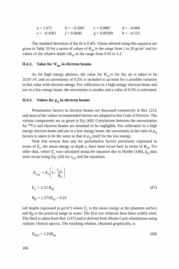
186
a = 1.075 b = –0.5087 c = 0.0887 d = –0.084 e = –0.4281 f = 0.0646 g = 0.00309 h = –0.125
The standard deviation of the fit is 0.4%. Values derived using this equation aregiven in Table 20 for a series of values of R50 in the range from 1 to 20 g/cm2 and forvalues of the relative depth z/R50 in the range from 0.02 to 1.2.
II.4.2. Value for Wair in electron beams
As for high energy photons, the value for Wair/e for dry air is taken to be33.97 J/C and an uncertainty of 0.5% is included to account for a possible variationin this value with electron energy. For calibration in a high energy electron beam anduse in a low energy beam, the uncertainty is smaller and a value of 0.3% is estimated.
II.4.3. Values for pQ in electron beams
Perturbation factors in electron beams are discussed extensively in Ref. [21],and most of the values recommended therein are adopted in this Code of Practice. Thevarious components are as given in Eq. (60). Correlations between the uncertaintiesfor 60Co and electron beams are assumed to be negligible. For calibration in a highenergy electron beam and use in a low energy beam, the uncertainty in the ratio of pQfactors is taken to be the same as that in pQ itself for the low energy.
Note that several data sets for perturbation factors previously expressed interms of Ez, the mean energy at depth z, have been recast here in terms of R50. Forolder data, where Ez was calculated using the equation due to Harder [146], pQ datawere recast using Eq. (24) for zref and the equations
Eo = 2.33 R50 (67)
Rp = 1.271R50 – 0.23
(all depths expressed in g/cm2) where Eo is the mean energy at the phantom surfaceand Rp is the practical range in water. The first two relations have been widely used.The third is taken from Ref. [147] and is derived from Monte Carlo simulations usingrealistic clinical spectra. The resulting relation, obtained graphically, is
Ezref = 1.23R50 (68)
refref
1op
zz
E ER
Ê ˆ= -Á ˜Ë ¯
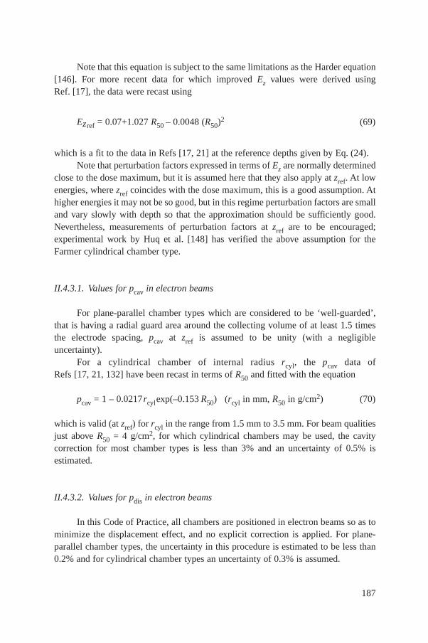
Note that this equation is subject to the same limitations as the Harder equation[146]. For more recent data for which improved Ez values were derived usingRef. [17], the data were recast using
Ezref = 0.07+1.027 R50 – 0.0048 (R50)2 (69)
which is a fit to the data in Refs [17, 21] at the reference depths given by Eq. (24).Note that perturbation factors expressed in terms of Ez are normally determined
close to the dose maximum, but it is assumed here that they also apply at zref. At lowenergies, where zref coincides with the dose maximum, this is a good assumption. Athigher energies it may not be so good, but in this regime perturbation factors are smalland vary slowly with depth so that the approximation should be sufficiently good.Nevertheless, measurements of perturbation factors at zref are to be encouraged;experimental work by Huq et al. [148] has verified the above assumption for theFarmer cylindrical chamber type.
II.4.3.1. Values for pcav in electron beams
For plane-parallel chamber types which are considered to be ‘well-guarded’,that is having a radial guard area around the collecting volume of at least 1.5 timesthe electrode spacing, pcav at zref is assumed to be unity (with a negligibleuncertainty).
For a cylindrical chamber of internal radius rcyl, the pcav data of Refs [17, 21, 132] have been recast in terms of R50 and fitted with the equation
pcav = 1 – 0.0217rcylexp(–0.153 R50) (rcyl in mm, R50 in g/cm2) (70)
which is valid (at zref) for rcyl in the range from 1.5 mm to 3.5 mm. For beam qualitiesjust above R50 = 4 g/cm2, for which cylindrical chambers may be used, the cavitycorrection for most chamber types is less than 3% and an uncertainty of 0.5% isestimated.
II.4.3.2. Values for pdis in electron beams
In this Code of Practice, all chambers are positioned in electron beams so as tominimize the displacement effect, and no explicit correction is applied. For plane-parallel chamber types, the uncertainty in this procedure is estimated to be less than0.2% and for cylindrical chamber types an uncertainty of 0.3% is assumed.
187
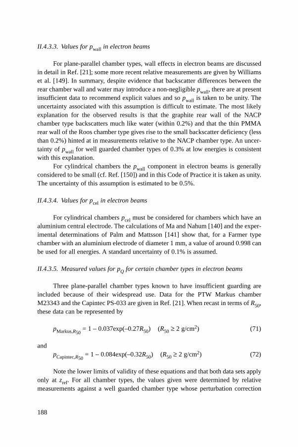
188
II.4.3.3. Values for pwall in electron beams
For plane-parallel chamber types, wall effects in electron beams are discussedin detail in Ref. [21]; some more recent relative measurements are given by Williamset al. [149]. In summary, despite evidence that backscatter differences between therear chamber wall and water may introduce a non-negligible pwall, there are at presentinsufficient data to recommend explicit values and so pwall is taken to be unity. Theuncertainty associated with this assumption is difficult to estimate. The most likelyexplanation for the observed results is that the graphite rear wall of the NACPchamber type backscatters much like water (within 0.2%) and that the thin PMMArear wall of the Roos chamber type gives rise to the small backscatter deficiency (lessthan 0.2%) hinted at in measurements relative to the NACP chamber type. An uncer-tainty of pwall for well guarded chamber types of 0.3% at low energies is consistentwith this explanation.
For cylindrical chambers the pwall component in electron beams is generallyconsidered to be small (cf. Ref. [150]) and in this Code of Practice it is taken as unity.The uncertainty of this assumption is estimated to be 0.5%.
II.4.3.4. Values for pcel in electron beams
For cylindrical chambers pcel must be considered for chambers which have analuminium central electrode. The calculations of Ma and Nahum [140] and the exper-imental determinations of Palm and Mattsson [141] show that, for a Farmer typechamber with an aluminium electrode of diameter 1 mm, a value of around 0.998 canbe used for all energies. A standard uncertainty of 0.1% is assumed.
II.4.3.5. Measured values for pQ for certain chamber types in electron beams
Three plane-parallel chamber types known to have insufficient guarding areincluded because of their widespread use. Data for the PTW Markus chamberM23343 and the Capintec PS-033 are given in Ref. [21]. When recast in terms of R50,these data can be represented by
pMarkus,R50= 1 – 0.037exp(–0.27R50) (R50 ≥ 2 g/cm2) (71)
andpCapintec,R50
= 1 – 0.084exp(–0.32R50) (R50 ≥ 2 g/cm2) (72)
Note the lower limits of validity of these equations and that both data sets applyonly at zref. For all chamber types, the values given were determined by relativemeasurements against a well guarded chamber type whose perturbation correction
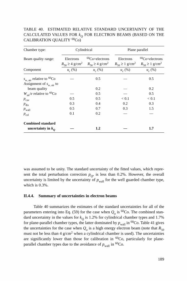
189
was assumed to be unity. The standard uncertainty of the fitted values, which repre-sent the total perturbation correction pQ, is less than 0.2%. However, the overalluncertainty is limited by the uncertainty of pwall for the well guarded chamber type,which is 0.3%.
II.4.4. Summary of uncertainties in electron beams
Table 40 summarizes the estimates of the standard uncertainties for all of theparameters entering into Eq. (59) for the case when Qo is 60Co. The combined stan-dard uncertainty in the values for kQ is 1.2% for cylindrical chamber types and 1.7%for plane-parallel chamber types, the latter dominated by pwall in 60Co. Table 41 givesthe uncertainties for the case when Qo is a high energy electron beam (note that R50must not be less than 4 g/cm2 when a cylindrical chamber is used). The uncertaintiesare significantly lower than those for calibration in 60Co, particularly for plane-parallel chamber types due to the avoidance of pwall in 60Co.
TABLE 40. ESTIMATED RELATIVE STANDARD UNCERTAINTY OF THECALCULATED VALUES FOR kQ FOR ELECTRON BEAMS (BASED ON THECALIBRATION QUALITY 60Co)
Chamber type: Cylindrical Plane parallel
Beam quality range: Electrons 60Co+electrons Electrons 60Co+electronsR50 ≥ 4 g/cm2 R50 ≥ 4 g/cm2 R50 ≥ 1 g/cm2 R50 ≥ 1 g/cm2
Component uc (%) uc (%) uc (%) uc (%)
sw, air relative to 60Co — 0.5 — 0.5Assignment of sw, air to
beam quality 0.2 — 0.2Wair/e relative to 60Co — 0.5 — 0.5pcav 0.5 0.5 < 0.1 < 0.1pdis 0.3 0.4 0.2 0.3pwall 0.5 0.7 0.3 1.5pcel 0.1 0.2 — —
Combined standard uncertainty in kQ — 1.2 — 1.7
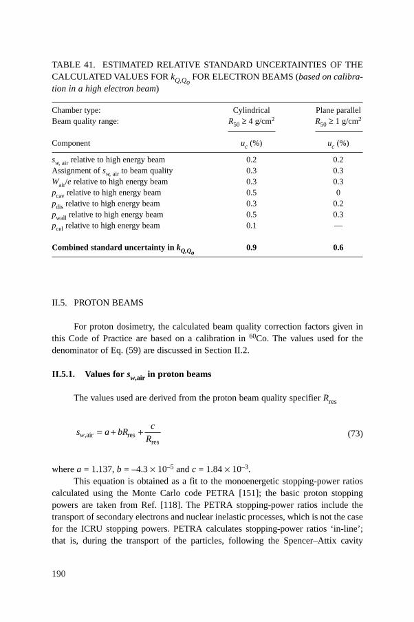
190
II.5. PROTON BEAMS
For proton dosimetry, the calculated beam quality correction factors given inthis Code of Practice are based on a calibration in 60Co. The values used for thedenominator of Eq. (59) are discussed in Section II.2.
II.5.1. Values for sw,air in proton beams
The values used are derived from the proton beam quality specifier Rres
(73)
where a = 1.137, b = –4.3 ¥ 10–5 and c = 1.84 ¥ 10–3.This equation is obtained as a fit to the monoenergetic stopping-power ratios
calculated using the Monte Carlo code PETRA [151]; the basic proton stoppingpowers are taken from Ref. [118]. The PETRA stopping-power ratios include thetransport of secondary electrons and nuclear inelastic processes, which is not the casefor the ICRU stopping powers. PETRA calculates stopping-power ratios ‘in-line’;that is, during the transport of the particles, following the Spencer–Attix cavity
wc
s a bRR,air res
res= + +
TABLE 41. ESTIMATED RELATIVE STANDARD UNCERTAINTIES OF THECALCULATED VALUES FOR kQ,Qo
FOR ELECTRON BEAMS (based on calibra-tion in a high electron beam)
Chamber type: Cylindrical Plane parallelBeam quality range: R50 ≥ 4 g/cm2 R50 ≥ 1 g/cm2
Component uc (%) uc (%)
sw, air relative to high energy beam 0.2 0.2Assignment of sw, air to beam quality 0.3 0.3Wair/e relative to high energy beam 0.3 0.3pcav relative to high energy beam 0.5 0pdis relative to high energy beam 0.3 0.2pwall relative to high energy beam 0.5 0.3pcel relative to high energy beam 0.1 —
Combined standard uncertainty in kQ,Qo0.9 0.6
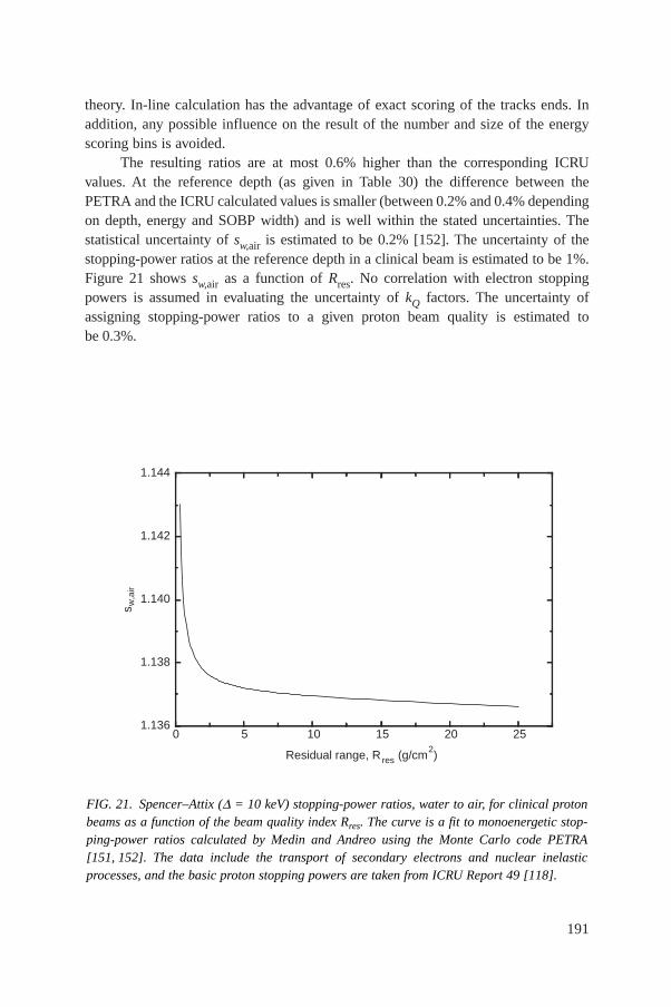
theory. In-line calculation has the advantage of exact scoring of the tracks ends. Inaddition, any possible influence on the result of the number and size of the energyscoring bins is avoided.
The resulting ratios are at most 0.6% higher than the corresponding ICRUvalues. At the reference depth (as given in Table 30) the difference between thePETRA and the ICRU calculated values is smaller (between 0.2% and 0.4% dependingon depth, energy and SOBP width) and is well within the stated uncertainties. Thestatistical uncertainty of sw,air is estimated to be 0.2% [152]. The uncertainty of thestopping-power ratios at the reference depth in a clinical beam is estimated to be 1%.Figure 21 shows sw,air as a function of Rres. No correlation with electron stoppingpowers is assumed in evaluating the uncertainty of kQ factors. The uncertainty ofassigning stopping-power ratios to a given proton beam quality is estimated tobe 0.3%.
191
FIG. 21. Spencer–Attix (D = 10 keV) stopping-power ratios, water to air, for clinical protonbeams as a function of the beam quality index Rres. The curve is a fit to monoenergetic stop-ping-power ratios calculated by Medin and Andreo using the Monte Carlo code PETRA[151, 152]. The data include the transport of secondary electrons and nuclear inelasticprocesses, and the basic proton stopping powers are taken from ICRU Report 49 [118].
0 5 10 15 20 251.136
1.138
1.140
1.142
1.144
s w,a
ir
Residual range, R res (g/cm2)
192
II.5.2. Value for Wair in proton beams
A comprehensive review of the literature on the value for Wair(E), includingvalues obtained from the comparison of calorimetric and ionometric methods, ispresented in Ref. [116]. Moreover, the ICRU report presents an extensive discussionon the difference between Wg(E), the mean energy required for charged particles ofenergy E to create an electron–ion pair in a gas g, and wg(E), the differential value.Since in this Code of Practice the PETRA stopping-power ratios are recommended,the values for Wair(E) given in Ref. [116] (namely those obtained from comparisonsof calorimetric and ionometric measurements) must be corrected to account for thesmall differences between the PETRA and ICRU stopping-power ratios. A procedureusing weighted medians, taking into account the statistical uncertainty of each value[153, 154], yields the value Wair /e = 34.23 J/C, with a standard uncertainty of 0.4%.This uncertainty can be compared with the uncertainty of 0.2% for the Wair /e valuefor electrons, which was obtained by the same statistical method.46
Until more information is available, the value Wair /e = 34.23 J/C and a standarduncertainty of 0.4% are recommended for proton dosimetry, and these values are usedin this Code of Practice.
II.5.3. Values for pQ in proton beams
Experimental information on perturbation factors in proton beams is currentlyonly available for a limited number of ionization chambers at a specific protonenergy; therefore all components are taken to be unity. The discussion below concen-trates on the uncertainties.
II.5.3.1. Values for pcav in proton beams
The uncertainty of pcav may be considered in two parts, corresponding to thecontributions of secondary electrons and of heavier secondary particles. The slowingdown of the secondary electrons generated in a proton beam is similar to that for pho-tons (60Co or high energy photons) and so the negligible uncertainty assumed for thephoton case may also be assumed for protons. The uncertainty of the heavier particlecontribution is taken to be 0.3%, for both plane-parallel and cylindrical chambers.
46 It is possible to arrive at the same average value using a simple “robust fit”, whichminimizes the influence of outliers (see Ref. [155]), but the procedure given in this referencedoes not allow statistical weights to be taken into account in determining the uncertainty.
193
II.5.3.2. Values for pdis in proton beams
Since the reference depth (as given in Table 30) is situated in a uniform doseregion, pdis is taken to be unity. The magnitude of the correction is unlikely to exceed0.5%. This includes the effect of possible ripples in the SOBP and a small dosegradient in the plateau region. It should be stressed that this effect might depend onthe resolution of the modulation, influencing the dose uniformity in the SOBP. Anuncertainty of 0.2% is estimated for this correction, for both plane-parallel and cylin-drical chambers.
II.5.3.3. Values for pwall in proton beams
Monte Carlo calculations by Palmans and Verhaegen [117] indicate a possibleeffect on pwall due to the influence of secondary electrons. Recent measurements[156] confirmed these calculations for certain wall materials; however, the effectwould not be larger than 0.5%. Therefore, pwall is currently taken to be equal to unity.In estimating the uncertainty, a similar argument to that for pcav may be applied topwall, namely that the uncertainty arising from the secondary electron componentshould be similar to that for photons, which is 0.5%. Likewise, a heavy particle con-tribution of 0.3% is assumed. A component of 0.2% arising from the primary pro-tons is also included, giving a combined uncertainty of 0.6%, for both plane-paralleland cylindrical chambers.
II.5.3.4. Values for pcel in proton beams
For chamber types with an aluminium central electrode, a value for pcel of 0.997was reported by Medin et al. [54] for a 170 MeV proton beam and of 1.00 by Palmanset al. [156] in a 75 MeV proton beam. The value 1.0 is used in this Code of Practicealong with their stated uncertainty of 0.4%, which is adopted for all cylindrical ion-ization chambers.
II.5.4. Summary of uncertainties in proton beams
Table 42 summarizes the uncertainty estimates and shows a combined standarduncertainty in kQ for proton beams of 1.7% and 2.1% for cylindrical and plane-parallel ionization chambers, respectively. The largest component of this uncertaintyis the uncertainty of sw,air and the uncertainty of pwall for plane-parallel ionizationchambers in the 60Co reference beam.
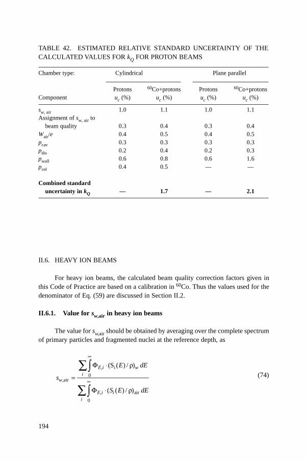
194
II.6. HEAVY ION BEAMS
For heavy ion beams, the calculated beam quality correction factors given inthis Code of Practice are based on a calibration in 60Co. Thus the values used for thedenominator of Eq. (59) are discussed in Section II.2.
II.6.1. Value for sw,air in heavy ion beams
The value for sw,air should be obtained by averaging over the complete spectrumof primary particles and fragmented nuclei at the reference depth, as
(74)E,i w
iw
E,i ii
E dE
s
S E dE
i
0,air
air
0
(S ( ) / )
( ( ) / )
•
•
F ◊ r
=
F ◊ r
ÂÚ
ÂÚ
TABLE 42. ESTIMATED RELATIVE STANDARD UNCERTAINTY OF THECALCULATED VALUES FOR kQ FOR PROTON BEAMS
Chamber type: Cylindrical Plane parallel
Protons 60Co+protons Protons 60Co+protonsComponent uc (%) uc (%) uc (%) uc (%)
sw, air 1.0 1.1 1.0 1.1Assignment of sw, air to
beam quality 0.3 0.4 0.3 0.4Wair/e 0.4 0.5 0.4 0.5pcav 0.3 0.3 0.3 0.3pdis 0.2 0.4 0.2 0.3pwall 0.6 0.8 0.6 1.6pcel 0.4 0.5 — —
Combined standard uncertainty in kQ — 1.7 — 2.1
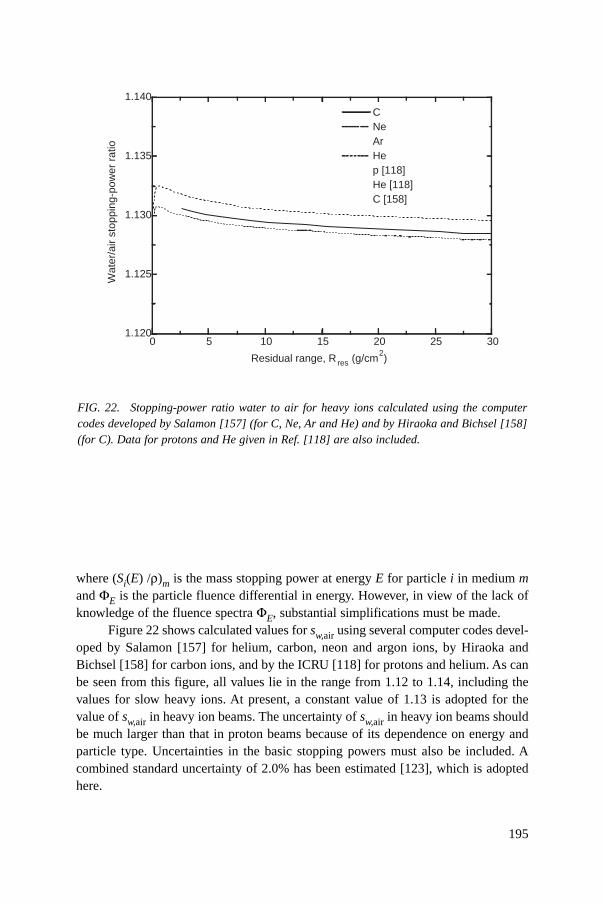
195
where (Si(E) /r)m is the mass stopping power at energy E for particle i in medium mand FE is the particle fluence differential in energy. However, in view of the lack ofknowledge of the fluence spectra FE, substantial simplifications must be made.
Figure 22 shows calculated values for sw,air using several computer codes devel-oped by Salamon [157] for helium, carbon, neon and argon ions, by Hiraoka andBichsel [158] for carbon ions, and by the ICRU [118] for protons and helium. As canbe seen from this figure, all values lie in the range from 1.12 to 1.14, including thevalues for slow heavy ions. At present, a constant value of 1.13 is adopted for thevalue of sw,air in heavy ion beams. The uncertainty of sw,air in heavy ion beams shouldbe much larger than that in proton beams because of its dependence on energy andparticle type. Uncertainties in the basic stopping powers must also be included. Acombined standard uncertainty of 2.0% has been estimated [123], which is adoptedhere.
FIG. 22. Stopping-power ratio water to air for heavy ions calculated using the computercodes developed by Salamon [157] (for C, Ne, Ar and He) and by Hiraoka and Bichsel [158](for C). Data for protons and He given in Ref. [118] are also included.
Residual range, R res (g/cm2)
0 5 10 15 20 25 301.120
1.125
1.130
1.135
1.140
C Ne Ar He p [118] He [118] C [158]
Wat
er/a
ir st
oppi
ng-p
ower
rat
io
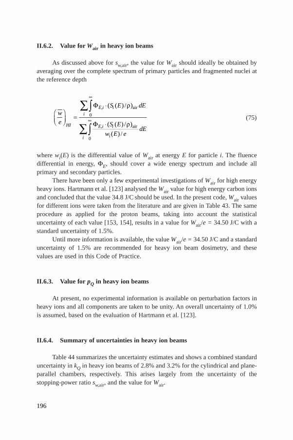
II.6.2. Value for Wair in heavy ion beams
As discussed above for sw,air, the value for Wair should ideally be obtained byaveraging over the complete spectrum of primary particles and fragmented nuclei atthe reference depth
(75)
where wi(E) is the differential value of Wair at energy E for particle i. The fluencedifferential in energy, FE, should cover a wide energy spectrum and include allprimary and secondary particles.
There have been only a few experimental investigations of Wair for high energyheavy ions. Hartmann et al. [123] analysed the Wair value for high energy carbon ionsand concluded that the value 34.8 J/C should be used. In the present code, Wair valuesfor different ions were taken from the literature and are given in Table 43. The sameprocedure as applied for the proton beams, taking into account the statisticaluncertainty of each value [153, 154], results in a value for Wair/e = 34.50 J/C with astandard uncertainty of 1.5%.
Until more information is available, the value Wair/e = 34.50 J/C and a standarduncertainty of 1.5% are recommended for heavy ion beam dosimetry, and thesevalues are used in this Code of Practice.
II.6.3. Value for pQ in heavy ion beams
At present, no experimental information is available on perturbation factors inheavy ions and all components are taken to be unity. An overall uncertainty of 1.0%is assumed, based on the evaluation of Hartmann et al. [123].
II.6.4. Summary of uncertainties in heavy ion beams
Table 44 summarizes the uncertainty estimates and shows a combined standarduncertainty in kQ in heavy ion beams of 2.8% and 3.2% for the cylindrical and plane-parallel chambers, respectively. This arises largely from the uncertainty of thestopping-power ratio sw,air, and the value for Wair.
air
0
air
0
( ( ) / )
( ( ) / )
( ) /
E,i ii
HI E,i i
ii
S E dEw
e S EdE
w E e
•
•
F ◊ rÊ ˆ =Á ˜Ë ¯ F ◊ r
ÂÚ
ÂÚ
196
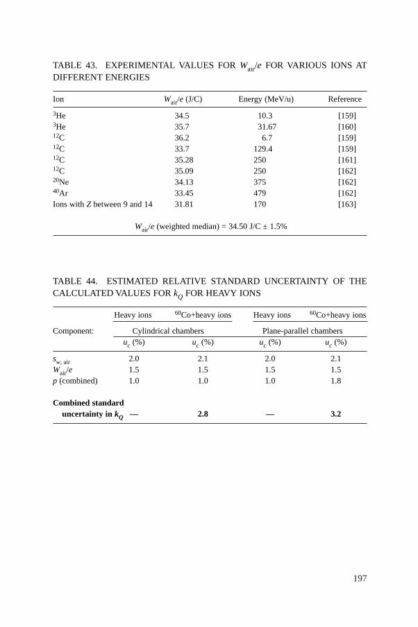
197
TABLE 43. EXPERIMENTAL VALUES FOR Wair/e FOR VARIOUS IONS ATDIFFERENT ENERGIES
Ion Wair/e (J/C) Energy (MeV/u) Reference
3He 34.5 10.3 [159]3He 35.7 31.67 [160]12C 36.2 6.7 [159]12C 33.7 129.4 [159]12C 35.28 250 [161]12C 35.09 250 [162]20Ne 34.13 375 [162]40Ar 33.45 479 [162]Ions with Z between 9 and 14 31.81 170 [163]
Wair/e (weighted median) = 34.50 J/C ± 1.5%
TABLE 44. ESTIMATED RELATIVE STANDARD UNCERTAINTY OF THECALCULATED VALUES FOR kQ FOR HEAVY IONS
Heavy ions 60Co+heavy ions Heavy ions 60Co+heavy ions
Component: Cylindrical chambers Plane-parallel chambersuc (%) uc (%) uc (%) uc (%)
sw, air 2.0 2.1 2.0 2.1Wair/e 1.5 1.5 1.5 1.5p (combined) 1.0 1.0 1.0 1.8
Combined standard uncertainty in kQ — 2.8 — 3.2

198
Appendix III
PHOTON BEAM QUALITY SPECIFICATION47
The specification of the quality of a photon beam has been the subject ofnumerous studies due to its relevance in radiation dosimetry. However, no beamquality specifier has been found that satisfies all possible requirements of being aunique specifier for the entire energy range of photon energies used in radiotherapyand all possible accelerators used in hospitals and standards laboratories. Discussionsraised in this context are described in this appendix in order to provide a reasoneddiscussion of the advantages and disadvantages of using TPR20,10 versus other spec-ifiers, specifically PDD(10)x proposed by Kosunen and Rogers [164] and used in thedosimetry protocol of the American Association of Physicists in Medicine TaskGroup 51 [51]. For completeness, an overview of common photon beam quality spec-ifiers used in radiotherapy dosimetry is given here based on the description providedby the ICRU report on the dosimetry of high energy photon beams based on standardsof absorbed dose to water [29].
III.1. OVERVIEW OF COMMON PHOTON BEAM QUALITY SPECIFIERS
Most dosimetry protocols, based on both standards of air kerma and standardsof absorbed dose to water, have recommended the tissue phantom ratio, TPR20,10, asspecifier of the quality of a high energy photon beam [9, 12–14, 17, 19, 49, 50].TPR20,10 is defined as the ratio of water absorbed doses on the beam axis at the depthsof 20 cm and 10 cm in a water phantom, obtained with a constant source detectordistance (SDD) of 100 cm and a 10 cm × 10 cm field size at the position of thedetector. The parameter TPR20,10 is a measure of the effective attenuation coefficientdescribing the approximately exponential decrease of a photon depth dose curvebeyond the depth of maximum dose [82–84] and, more importantly, it is independentof the electron contamination in the incident beam.
Prior to the use of dose ratios for specifying photon beam quality, the nominalaccelerator potential was the parameter most commonly used in photon beamdosimetry. Measured ionization (charge or current) or absorbed dose ratios were firstused as a beam quality index in the dosimetry recommendations of the NordicAssociation of Clinical Physicists (NACP) [8, 165]. The measured ratio in a clinical
47 Part of this appendix has been adopted from Ref. [85] and is reproduced here withthe permission of the American Association of Physicists in Medicine.
199
treatment unit was, however, associated with a generic nominal accelerator energy(nominal accelerating potential or nominal maximum energy, expressed in MV), whichwas then used for the selection of conversion factors. A first attempt at improving theNACP procedure was made in Ref. [9]. Data in Ref. [9] for stopping-power ratios, massenergy absorption coefficient ratios, etc., were still given numerically as a function ofthe nominal MV, but these data were associated in graphical form with measuredionization ratios. There were, however, two limitations in the Ref. [9] method: (i) therelation between measured and calculated ionization ratios was based on inaccuratecalculations, and (ii) the graphical procedure also involved a unique correspondencebetween MV and ionization ratios, similar to the drawback pointed out for the NACPrecommendations [8, 165]. Andreo and Brahme [78] showed that the use of only thenominal accelerator potential, ignoring the actual penetration properties of a clinicalbeam, could yield variations of up to 1.5% in the stopping-power ratio. It is mainly forthis reason that the use of TPR20,10 was considered to be the more appropriate choicefor radiotherapy beams, rather than using the nominal accelerating potential.
Other beam quality specifiers have been proposed for photon beam dosimetrywhich are, in most cases, related to the depth of maximum absorbed dose and can,therefore, be affected by the electron contamination at this depth. In addition, the useof ionization distributions measured with thimble type ionization chambers is prob-lematic, as the displacement of phantom material by the detector has to be taken intoaccount to convert ionization into dose distributions. This is avoided if plane-parallelionization chambers are used, but these are not common in photon beam dosimetry.
Based on percentage depth dose distributions, a widely disseminated recom-mendation for specifying the quality of high energy photon beams was made inSupplement 17 of the British Journal of Radiology (BJR) [87]. This supplementdefined the parameter d80 as the depth of the 80% depth dose (i.e. 80% of the dosemaximum) for a 10 cm × 10 cm field size at an SSD of 100 cm. In Ref. [87] it waspointed out that electron contamination should be considered a practical shortcomingof the method. The use of d80 as a photon beam quality index has also been endorsedin Supplement 25 of the British Journal of Radiology [81], although other beamquality specifiers, like PDD(10) below, are also considered. In its conclusions,Supplement 25 also referred to contaminating electrons as the greatest problem fornormalization at zmax, as by changing the dose at this depth electron contaminationcan alter the apparent beam quality. It is interesting to note that even sinceSupplement 11 of the British Journal of Radiology [166], the problem of electroncontamination and the need to normalize dose distributions at depths larger than zmaxhas been addressed by different BJR supplements, but alternatives for a specifierindependent of electron contamination have not been proposed in this series ofpublications.
The parameter PDD(10), the percentage depth dose at 10 cm depth, determinedunder the same conditions of field size and SSD as d80, has the same limitation with
200
regard to the effect of electron contamination as d80. This parameter has been com-monly used by accelerator manufacturers, associating it with an effective acceleratorpotential. The work by LaRiviere [167], proposing a relation between the beamquality specified in terms of MV and PDD(10), has been used by manufacturers tojustify the use of this parameter. This has, however, produced the paradoxicalsituation where an accelerator could have an effective MV larger than the acceleratorelectron energy.
LaRiviere [167] also proposed a relation between PDD(10) and the doseweighted mean energy of the photon spectrum, which was suggested as an alternativebeam quality index. That proposal led Kosunen and Rogers [164] to investigate therelation of PDD(10)x in a ‘pure photon beam’ (i.e. without electron contamination) tostopping-power ratios. Based on the linearity of the relation obtained, they proposedextending the use of PDD(10)x to specify the quality of photon beams and to selectconversion and correction factors. Kosunen and Rogers referred to the problem of thedifference between absorbed dose and ionization measurements with cylindricalionization chambers due to the use of a displacement (or replacement) factor, and alsoemphasized that electron contamination should be removed from the photon beam formeasuring PDD(10)x. According to these authors the latter can be achieved using athin lead foil as filter, which has become the method recommended in Ref. [51].
III.2. ADVANTAGES AND DISADVANTAGES OF TPR20,10
For clinical beams in the most widely used energy region (TPR20,10 betweenapproximately 0.50 and 0.70)48, the small variation of stopping-power ratios, andtherefore in ND,w, with TPR20,10 has an important advantage in the final uncertaintyof the determination of the absorbed dose to water at the reference point, as possibleerrors in the measurement of TPR20,10 do not yield a significant change in the valueof the stopping-power ratio [22]. From a compilation of 21 clinical spectra publishedby different authors and 16 additional calculated spectra corresponding to clinicalbeams [78], it has been shown that stopping-power ratios and TPR20,10 are very wellcorrelated and lie on an almost universal curve. These stopping-power ratios can befitted to better than 0.15% for practically all the clinical spectra with a cubic
48 In a large survey carried out by the Radiological Physics Center in Houston [168], forwhich the summary of RPC measured depth dose data was updated in 1996 (W. Hanson,private communication), of approximately 1200 clinical accelerators investigated in NorthAmerica, more than 80% of the machines had a maximum nominal accelerating potential of10 MV or less. This figure is expected to be even larger in developing countries.
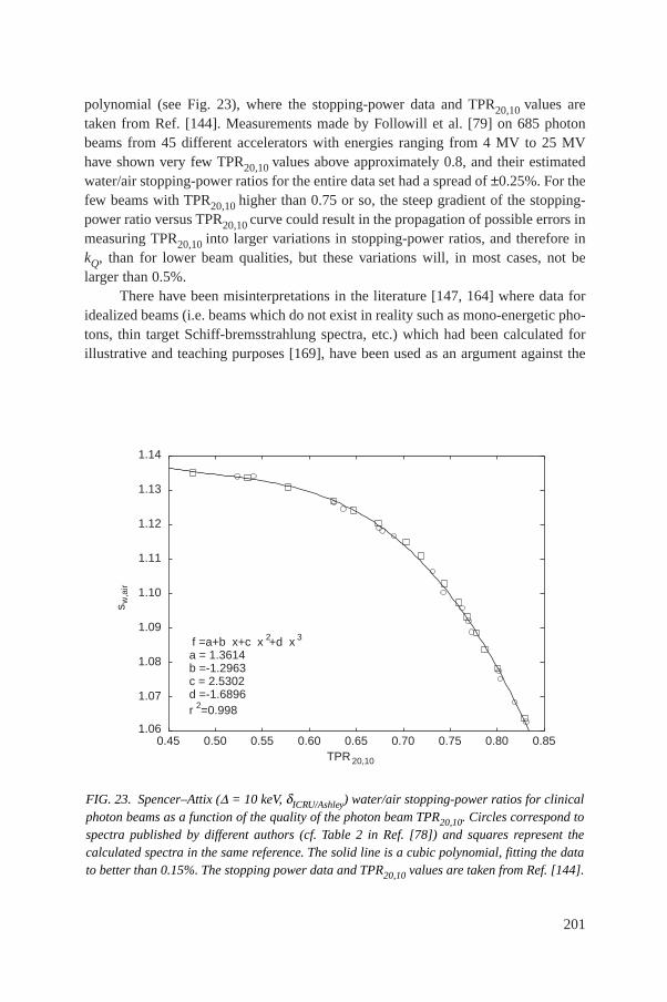
polynomial (see Fig. 23), where the stopping-power data and TPR20,10 values aretaken from Ref. [144]. Measurements made by Followill et al. [79] on 685 photonbeams from 45 different accelerators with energies ranging from 4 MV to 25 MVhave shown very few TPR20,10 values above approximately 0.8, and their estimatedwater/air stopping-power ratios for the entire data set had a spread of ±0.25%. For thefew beams with TPR20,10 higher than 0.75 or so, the steep gradient of the stopping-power ratio versus TPR20,10 curve could result in the propagation of possible errors inmeasuring TPR20,10 into larger variations in stopping-power ratios, and therefore inkQ, than for lower beam qualities, but these variations will, in most cases, not belarger than 0.5%.
There have been misinterpretations in the literature [147, 164] where data foridealized beams (i.e. beams which do not exist in reality such as mono-energetic pho-tons, thin target Schiff-bremsstrahlung spectra, etc.) which had been calculated forillustrative and teaching purposes [169], have been used as an argument against the
201
s w,a
ir
1.06
1.07
1.08
1.09
1.10
1.11
1.12
1.13
1.14
0.45 0.50 0.55 0.60 0.65 0.70 0.75 0.80 0.85TPR 20,10
f =a+b x+c x 2+d x 3
a = 1.3614b =-1.2963c = 2.5302d =-1.6896r 2=0.998
FIG. 23. Spencer–Attix (D = 10 keV, dICRU/Ashley) water/air stopping-power ratios for clinicalphoton beams as a function of the quality of the photon beam TPR20,10. Circles correspond tospectra published by different authors (cf. Table 2 in Ref. [78]) and squares represent thecalculated spectra in the same reference. The solid line is a cubic polynomial, fitting the datato better than 0.15%. The stopping power data and TPR20,10 values are taken from Ref. [144].
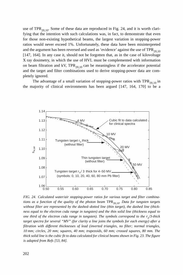
202
use of TPR20,10. Some of these data are reproduced in Fig. 24, and it is worth clari-fying that the intention with such calculations was, in fact, to demonstrate that evenfor those non-existing hypothetical beams, the largest variation in stopping-powerratios would never exceed 1%. Unfortunately, these data have been misinterpretedand the argument has been reversed and used as ‘evidence’ against the use of TPR20,10[147, 164]. In any case it, should not be forgotten that, as in the case of kilovoltageX ray dosimetry, in which the use of HVL must be complemented with informationon beam filtration and kV, TPR20,10 can be meaningless if the accelerator potentialand the target and filter combinations used to derive stopping-power data are com-pletely ignored.
The advantage of a small variation of stopping-power ratios with TPR20,10 inthe majority of clinical environments has been argued [147, 164, 170] to be a
FIG. 24. Calculated water/air stopping-power ratios for various target and filter combina-tions as a function of the quality of the photon beam TPR20,10. Data for tungsten targetswithout filter are represented by the dashed–dotted line (thin target), the dashed line (thick-ness equal to the electron csda range in tungsten) and the thin solid line (thickness equal toone third of the electron csda range in tungsten). The symbols correspond to the ro/3-thicktarget spectra for several “MV” (for clarity a line joins the symbols for each energy) after afiltration with different thicknesses of lead (inverted triangles, no filter; normal triangles,10 mm; circles, 20 mm; squares, 40 mm; trapezoids, 60 mm; crossed squares, 80 mm. Thethick solid line is the cubic fit to data calculated for clinical beams shown in Fig. 23. The figureis adapted from Refs [53, 84].
s w,a
ir
1.06
1.07
1.08
1.09
1.10
1.11
1.12
1.13
1.14
0.50 0.55 0.60 0.65 0.70 0.75 0.80 0.85
10 MV
20 MV
50 MV
Cubic fit to data calculatedfor clinical spectra
4 MV
Tungsten target r / 3 o thick for 4–50 MV(symbols: 0, 10, 20, 40, 60, 80 mm Pb filter)
Thin tungsten target(without filter)
Tungsten target ro thick (without filter)
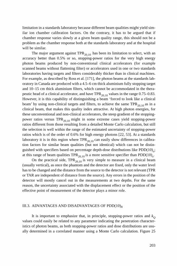
203
limitation in a standards laboratory because different beam qualities might yield sim-ilar ion chamber calibration factors. On the contrary, it has to be argued that ifchamber response varies slowly at a given beam quality range, this should not be aproblem as the chamber response both at the standards laboratory and at the hospitalwill be similar.
The major argument against TPR20,10 has been its limitation to select, with anaccuracy better than 0.5% or so, stopping-power ratios for the very high energyphoton beams produced by non-conventional clinical accelerators (for examplescanned beams without flattening filter) or accelerators used in one or two standardslaboratories having targets and filters considerably thicker than in clinical machines.For example, as described by Ross et al. [171], the photon beams at the standards lab-oratory in Canada are produced with a 4.5–6 cm thick aluminium fully stopping targetand 10–15 cm thick aluminium filters, which cannot be accommodated in the thera-peutic head of a clinical accelerator, and have TPR20,10 values in the range 0.75–0.83.However, it is this capability of distinguishing a beam ‘forced to look like a clinicalbeam’ by using non-clinical targets and filters, to achieve the same TPR20,10 as in aclinical beam, that makes this quality index attractive. At high photon energies, forthese unconventional and non-clinical accelerators, the steep gradient of the stopping-power ratios versus TPR20,10 might in some extreme cases yield stopping-powerratios different from those resulting from a detailed Monte Carlo calculation, but stillthe selection is well within the range of the estimated uncertainty of stopping-powerratios which is of the order of 0.6% for high energy photons [22, 53]. At a standardslaboratory it is in this region where TPR20,10 can easily show differences in calibra-tion factors for similar beam qualities (but not identical) which can not be distin-guished with specifiers based on percentage depth-dose distributions like PDD(10)x;at this range of beam qualities TPR20,10 is a more sensitive specifier than PDD(10)x.
On the practical side, TPR20,10 is very simple to measure in a clinical beam(usually vertical), as once the phantom and the detector are fixed, only the water levelhas to be changed and the distance from the source to the detector is not relevant (TPRor TAR are independent of distance from the source). Any errors in the position of thedetector will mostly cancel out in the measurements at two depths. For the samereason, the uncertainty associated with the displacement effect or the position of theeffective point of measurement of the detector plays a minor role.
III.3. ADVANTAGES AND DISADVANTAGES OF PDD(10)x
It is important to emphasize that, in principle, stopping-power ratios and kQvalues could easily be related to any parameter indicating the penetration character-istics of photon beams, as both stopping-power ratios and dose distributions are usu-ally determined in a correlated manner using a Monte Carlo calculation. Figure 25
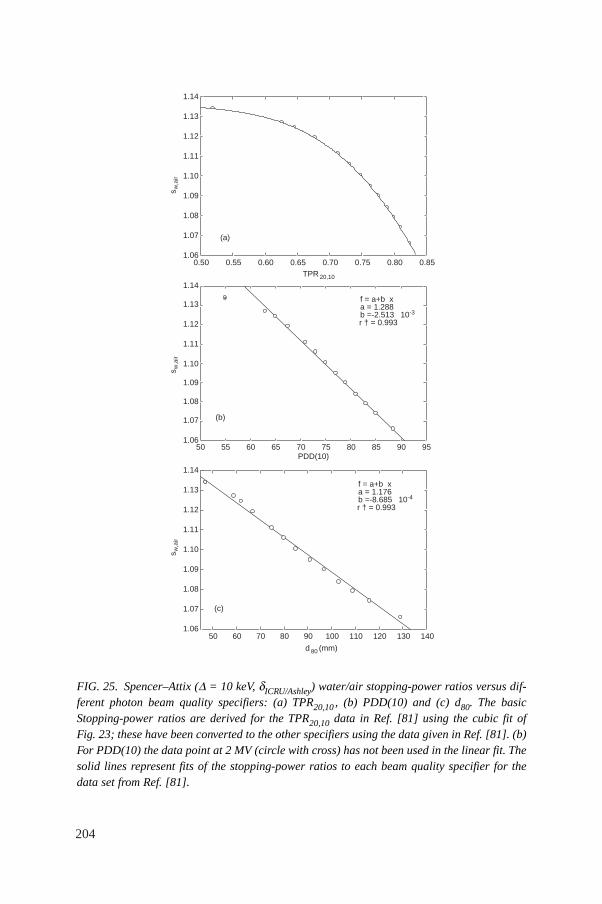
204
FIG. 25. Spencer–Attix (D = 10 keV, dICRU/Ashley) water/air stopping-power ratios versus dif-ferent photon beam quality specifiers: (a) TPR20,10 , (b) PDD(10) and (c) d80. The basicStopping-power ratios are derived for the TPR20,10 data in Ref. [81] using the cubic fit ofFig. 23; these have been converted to the other specifiers using the data given in Ref. [81]. (b)For PDD(10) the data point at 2 MV (circle with cross) has not been used in the linear fit. Thesolid lines represent fits of the stopping-power ratios to each beam quality specifier for thedata set from Ref. [81].
TPR 20,10
0.50 0.55 0.60 0.65 0.70 0.75 0.80 0.851.06
1.07
1.08
1.09
1.10
1.11
1.12
1.13
1.14
1.06
1.07
1.08
1.09
1.10
1.11
1.12
1.13
1.14
1.06
1.07
1.08
1.09
1.10
1.11
1.12
1.13
1.14
(a)
PDD(10)50 55 60 65 70 75 80 85 90 95
(b)
d 80 (mm)
50 60 70 80 90 100 110 120 130 140
f = a+b xa = 1.176b =-8.685 10-4
r † = 0.993
f = a+b xa = 1.288b =-2.513 10-3
r † = 0.993
(c)
s w,a
irs w
,air
s w,a
ir
TPR 20,10
illustrates the variation of water/air stopping-power ratios with different photon beamquality specifiers, TPR20,10, PDD(10) and d80, using the beam quality parametersgiven in Table 5.iii of BJR Supplement 25 [81]. The basic stopping-power ratios werefirst obtained for the TPR20,10 data using the fit given in Fig. 23 for clinical beamspectra, and then were converted to the other specifiers using data from Ref. [81].
The fits included in the plots show that it is possible to derive a close relationfor any specifier (the data point at 2 MV has not been included in the fit for PDD(10)given here, nor was it included in those given in Refs [164, 170, 172, 175]), andsimilar plots could have been produced also for broad or narrow beam attenuationcoefficients. Note in particular that the linear correlation with the beam quality spec-ifier recommended in Ref. [81], d80, is excellent for the entire range of energies usedin this comparison. Considering that the depth dose data have been averaged overmany types of clinical accelerators (from Ref. [81]), it could be assumed that thesesimple linear fits are representative of clinical data. However, as the electron contam-ination varies from machine to machine, this indirect procedure has never beenrecommended and only the data expressed as a function of TPR20,10 can be used inde-pendently of contamination.
Calculating the stopping-power ratio data directly as a function of PDD(10) ord80 for realistic beams is not possible due to the lack of information on the spectra ofcontaminant electrons, which would be required as input to the calculations. Instead,the parameter PDD(10)x, i.e. PDD(10) for ‘pure photon beams’, has been recom-mended to select stopping-power ratios [147, 164]. The problem is that in reality‘pure photon beams’ do not exist. Therefore, beam quality specification must relyeither on a simple practical parameter which is truly related to the intrinsic physics ofphoton interactions (like a practical attenuation coefficient, which is equivalent tousing TPR20,10), or the problems associated with electron contamination will cancelany possible theoretical advantage in a simple linear fit valid for most practicalbeams. In the latter case, the difficulty with relating a ‘pure photon beam’ parameterto a parameter easily measurable in a hospital is a major limitation which will bediscussed below. A related problem which has received little attention in the assign-ment of stopping-power ratios to Monte Carlo calculated depth dose distributions isthe statistical noise that appears in depth dose data. Figure 26 illustrates this situation,which is specially relevant in the region around the depth of maximum dose, zmax. Thehistogram in the figure corresponds to the simulation, using the Monte Carlo codeDOSRZ/EGS4 [174], of 15 million histories of 10 MeV monoenergetic photons in a1 mm depth grid, and shows the difficulty of finding values of the dose at zmax and ata single depth (for PDD(10) or d80) due to the statistical noise of the Monte Carlodata. For comparison, the solid line corresponds to a convolution of calculated energydeposition kernels which overcomes this problem; the procedure has been used toderive the correlation between TPR20,10 and stopping-power ratios in Ref. [144]shown in Fig. 23.
205
The linearity of the relation between PDD(10)x and stopping-power ratios forall types of beams, even for those not available in hospitals, has been a major argu-ment for promoting the use of PDD(10)x as a photon beam quality specifier and min-imizing the importance of electron contamination. There have been efforts by somestandards laboratories to have PDD(10)x accepted so that these laboratories can havetheir accelerators showing a specification similar to that found in clinical machines,even if the accelerator energy is very different. It is unfortunate that practically all theexperimental comparisons showing the ‘superiority’ of PDD(10)x over TPR20,10 havebeen made on non-clinical accelerators at standards laboratories [171, 175]. In arecent publication [176] where kQ values were determined in the photon beams of astandards laboratory, a statement concluding “support PDD(10) as a better beamquality specifier” was given even when the electron contamination contribution to thedose at zmax had been estimated in a crude way and PDD(10) corrected according to
206
FIG. 26. Comparison between central axis depth dose distributions for 10 MeV monoener-getic photon beams obtained from Monte Carlo simulations using the code DOSRZ/EGS4[174] (the histogram corresponds to 15 million photon histories using a 1 mm depth grid) andfrom the convolution of calculated energy deposition kernels (solid line). The plot illustratesthe difficulty of deriving values of the dose at zmax and at a single depth owing to the statis-tical noise of the Monte Carlo data, but the problem can be overcome with the use of kernels.The data are taken from Ref. [144].
Depth in water (cm)
0.125
0.130
0.135
0.140
0.145
0.150
0.155
20 30 40 50 60 70 80 90 100
Ene
rgy
depo
sitio
n pe
r in
cide
nt p
hoto
n (M
eV·c
m-2
·g-1
)
10 MeV photons
such an estimation. Other major laboratories, on the other hand, do have clinicalbeams or intend to install a clinical treatment head.
As all the specifiers based on percentage depth dose distributions are affectedby the electron contamination of the beam, identical photon spectra with differentcontamination would appear as having different qualities, even when their dosi-metric properties at depth (attenuation, stopping-power ratios, etc.) are the same.These specifiers thus have a closer relation to the manufacturer’s design of an accel-erator treatment head, which is the major source of contaminant electrons, than withthe physics governing the penetration of photon beams. To remove electron contam-ination an appropriate ‘electron filter’ should be used. The ideal solution would be apurging magnet (cf. Ref. [84]), but this is seldom available and only some versionsof racetrack microtron accelerators include such a device. As already mentioned, theuse of a lead foil has been suggested by a group of authors [164, 172], and this hasbeen the recommendation of the American Association Physicists in Medicine TaskGroup 51 protocol [51]. It is surprising that a material like lead has been recom-mended, when it has long been well known that lead in itself is an additional sourceof contaminant electrons. This was recognized in early radiotherapy in relation withskin sparing problems produced by electrons originated in lead blocks and, forinstance, ICRU Reports 10b and 10d [98, 177] recommended using materials ofintermediate atomic number, such as copper, iron or brass, as filters to minimizeelectron production.
Having decided that an electron lead filter will be used, a relation between theuncontaminated non-clinical photon beam and the contaminated clinical beam mustbe established for the accelerator and filter used in specific conditions. The termuncontaminated deserves special attention because the lead filter used to measuredepth dose data produces new electron contamination whose consequences have notbeen studied in detail for a large number of clinical photon spectra. What is availabletoday is a set of empirical equations, derived for a few examples, all requiring severalsteps and the use of multiple parameters and approximations. Rogers [147], forexample, has provided a relationship between PDD(10) and PDD(10)x which is basedonly on two sets of measured data. Also, the series of publications by Rogers andcolleagues on this topic [164, 170, 172, 173] is based on a so-called ‘standard set’ ofphoton beam spectra, which contains only five typical clinical beams (those calcu-lated by Mohan et al. [178]), but no further accelerator photon beams have beenmodelled and simple electron spectra have been used as inputs to some of thenecessary calculations [173]. Whereas the scientific interest of these calculations isunquestionable, on the practical side one could question if the uncertainty introducedby the various steps and general fits does not counter balance the hypothetical advan-tage of using a ‘pure photon beam’ parameter.
An elementary question which may be raised in relation to this topic is, if allelectron contamination can be removed from zmax, and a depth dose curve can be
207
measured with satisfactory accuracy by every user, then why is the depth of maximumdose zmax not recommended for photon beam calibration, instead of at a depth of10 cm? This would eliminate the step of transferring the dose from a larger depth tozmax, which is used by most medical physicists for performing clinical referencedosimetry. In this case, only a relative measurement between the filtered and the non-filtered beam would be necessary, exactly as for measuring relative field outputs. Thisquestion has not been addressed by the various publications which recommend thatPDD(10)x be used as a beam quality specifier [164, 170, 172, 173] nor by Ref. [51].
On the practical side, problems may arise in the measurement of PDD(10)x, inaddition to those related to the positioning of the lead filter whose distance to thephantom surface may be critical [173]. Because only one depth is relevant, this speci-fier is affected by errors in the positioning of the chamber at depth, although the influ-ence on the determination of absorbed dose is probably very small. Care should betaken when PDD(10)x is measured with cylindrical chambers due to the position of theeffective point of measurement of the ionization chamber, or to the need for using a dis-placement (replacement) factor for the measurement at 10 cm depth but not at the depthof the maximum absorbed dose. The depth of the maximum dose may be different inthe filtered and non-filtered beams, so that accurate depth doses down to at least 10 cmdepth need to be measured in both conditions, and it is well known that these may varywith the type of detector and measuring device used. Any systematic error in themeasuring set up (SSD, depths, etc.) will also change the measured PDD(10)x.
These practical problems and their influence on the final dose determinationhave been omitted in most occasions where PDD(10)x has been recommended as abeam quality specifier [164, 170, 172, 173] and in Ref. [51]. The user may thendecide that it is not worth measuring PDD(10)x under careful reference conditions.Even the possible impact of electron contamination has been minimized to such anextent in these references, where often a clear distinction between PDD(10)x andPDD(10) is omitted in the concluding remarks [164, 172], that users may feel it isunnecessary to use an electron filter for measuring PDD(10)x, and use insteadPDD(10) in an open beam (or the typical values given in Ref. [81]). This may beacceptable for relatively clean beams, yielding errors probably less than 0.5%, butmay have detrimental dosimetry consequences for beams with significant electroncontamination. The risk of users oversimplifying dosimetry procedures should not beignored or otherwise the possible advantages of implementing new dosimetryprotocols may be jeopardized.
III.4. CONCLUDING REMARKS
The general conclusion is that there is no unique beam quality specifier thatworks satisfactorily in all possible conditions for the entire energy range of photon
208
energies used in radiotherapy and all possible accelerators used in hospitals and instandards laboratories.
The most recent dosimetry protocols or codes of practice, based on the calibra-tion of ionization chambers in terms of absorbed dose to water, use a photon beamquality specifier in terms of TPR20,10 [49, 50], and this is also the choice in the presentInternational Code of Practice. The American Association of Physicists in MedicineTask Group 51 protocol [51] in North America uses PDD(10)x.
For a hospital user there is strictly no advantage of one index over the other, asboth sets of data, PDD and TPR (or TMR), are available for routine clinical use.However, there are more practical problems with measuring PDD(10)x than withTPR20,10, and errors in determining the beam quality index may have in general moreadverse consequences with PDD(10)x than with TPR20,10. The final impact on clinicalphoton beam dosimetry resulting from the use of different photon beam qualityspecifiers to select kQ values, is that they are not expected to yield a significant change(i.e. more than 0.5%, and in most cases they agree within 0.2% [179]) in the value ofthe absorbed dose to water in reference conditions for most clinical beams. Thisdifference is considerably smaller than the combined uncertainty of the differentfactors and coefficients used in photon dosimetry. In addition, for standard laborato-ries the use of PDD(10)x would require having different set ups for measuring beamquality and for the calibration of ionization chambers, which may result in increasedcalibration costs for the user. A change that does not improve photon dosimetry at thehospital and has so many complications from a practical point of view for the userdoes not appear to be justified.
209
Appendix IV
EXPRESSION OF UNCERTAINTIES
The evaluation of uncertainties in this Code of Practice follows the guidancegiven by the ISO [32]. In 1986 the ISO was given the task of developing detailedguidelines for the evaluation of uncertainties based on the new unified approach out-lined in the BIPM Recommendation INC-1. These recommendations were approvedby the Comité International des Poids et Mesures [180]. This effort resulted in theissue in 1993 of the ISO document entitled ‘Guide to the Expression of Uncertaintyin Measurement’, with a first corrected edition published in 1995 [32]. The guideshould be consulted for further details. This appendix provides practical implemen-tation of the ISO recommendations, based on the summaries provided inRefs [17, 33].
IV.1. GENERAL CONSIDERATIONS ON ERRORS AND UNCERTAINTIES
Contrary to earlier practice, when the terms error and uncertainty were usedinterchangeably, the modern approach, initiated by the Comité International des Poidset Mesures [180], distinguishes between these two concepts. Traditionally, an errorhas been viewed as having two components, namely a random component and a sys-tematic component. According to present definitions, an error is the differencebetween a measured value and the true value. If errors were known exactly, the truevalue could be determined; in reality, errors are estimated in the best possible way andcorrections are made for them. Therefore, after application of all known corrections,errors do not need any further consideration (their expectation value being zero) andthe quantities of interest are uncertainties. An error has both a numerical value and asign. In contrast, the uncertainty associated with a measurement is a parameter thatcharacterizes the dispersion of the values ‘that could reasonably be attributed to themeasurand’. This parameter is normally an estimated standard deviation. An uncer-tainty, therefore, has no known sign and is usually assumed to be symmetrical. It is ameasure of our lack of exact knowledge, after all recognized systematic effects havebeen eliminated by applying appropriate corrections.
Uncertainties of measurements are expressed as relative standard uncertaintiesand the evaluation of standard uncertainties is classified into type A and type B. Themethod of evaluation of type A standard uncertainties is by statistical analysis of aseries of observations, whereas the method of evaluation of type B standard uncer-tainties is based on means other than statistical analysis of a series of observations.
In the traditional categorization of uncertainties it was usual to distinguishbetween random and systematic contributions. This is undesirable because classifying
210
the components instead of the method of evaluation is prone to ambiguities. Forexample, a random component of uncertainty in one measurement may become asystematic component of uncertainty in another measurement in which the result ofthe first measurement is used as an input datum.
IV.2. TYPE A STANDARD UNCERTAINTIES
In a series of n measurements, with observed values xi, the best estimate of thequantity x is usually given by the arithmetic mean value
(76)
The scatter of the n measured values xi, around their mean x̄ can be character-ized by the standard deviation
(77)
and the quantity s2 (xi) is called the sample variance.We are often interested in the standard deviation of the mean value, written as
s(x̄), for which the general relation
(78)
applies. An alternative way to estimate s(x̄) would be based on the outcome of severalgroups of measurements. If they are all of the same size, the formulas given above canstill be used, provided that xi is now taken as the mean of group i and x̄ is the overallmean (or mean of the means) of the n groups. For groups of different size, statisticalweights would have to be used. This second approach may often be preferable, but itusually requires a larger number of measurements. A discussion of how much the tworesults of s(x̄) may differ from each other is beyond this elementary presentation.
The standard uncertainty of type A, denoted here by uA, will be identified withthe standard deviation of the mean value; that is
uA = s(x̄) (79)
1( ) ( )is x s x
n=
2
1
1( ) ( )
1
n
i ii
s x x xn
=
= -- Â
1
1n
ii
x xn
=
= Â
211
Obviously, an empirical determination of an uncertainty can not be expected togive its true value; it is by definition only an estimate. This is so for both type A andtype B uncertainties. It will be noted from Eq. (78) that a type A uncertainty on themeasurement of a quantity can, in principle, always be reduced by increasing thenumber n of individual readings. If several measurement techniques are available, thepreference will go to the one which gives the least scatter of the results, that is whichhas the smallest standard deviation s(xi), but in practice the possibilities for reductionare often limited.
In the past, uncertainties owing to random effects have often been evaluated inthe form of confidence limits, commonly at the 95% confidence level. This approachis not used now because there is no statistical basis for combining confidence limits.The theory of the propagation of uncertainties requires combination in terms ofvariances.
IV.3. TYPE B STANDARD UNCERTAINTIES
There are many sources of measurement uncertainty that can not be estimatedby repeated measurements. They are called type B uncertainties. These include notonly unknown, although suspected, influences on the measurement process, but alsolittle known effects of influence quantities (pressure, temperature, etc.), application ofcorrection factors or physical data taken from the literature, etc.
Type B uncertainties must be estimated so that they correspond to standard devi-ations; they are called type B standard uncertainties. Some experimenters claim thatthey can estimate directly this type of uncertainty, while others prefer to use, as an inter-mediate step, some type of limit. It is often helpful to assume that these uncertaintieshave a probability distribution which corresponds to some easily recognizable shape.
It is sometimes assumed, mainly for the sake of simplicity, that type B uncer-tainties can be described by a rectangular probability density, that is that they haveequal probability anywhere within the given maximum limits -M and +M. It can beshown that with this assumption, the type B standard uncertainty uB is given by
(80)
Alternatively, if the assumed distribution is triangular (with the same limits), weare led to the relation
(81)M
uB6
=
MuB
3=
212
Another assumption is that type B uncertainties have a distribution that isapproximately Gaussian (normal). On this assumption, the type B standard uncer-tainty can be derived by first estimating some limits ±L and then dividing that limitby a suitable number. If, for example, the experimenter is fairly sure of the limit L, itcan be considered to correspond approximately to a 95% confidence limit, whereas ifthe experimenter is almost certain, it may be taken to correspond approximately to a99% confidence limit. Thus, the type B standard uncertainty uB can be obtained fromthe equation
(82)
where k = 2 if the experimenter is fairly sure and k = 3 if the experimenter is almostcertain of his or her estimated limits ± L. These relations correspond to the propertiesof a Gaussian distribution and it is usually not worthwhile to apply divisors other than2 or 3 because of the approximate nature of the estimation.
There are thus no rigid rules for estimating type B standard uncertainties. Theexperimenter should use his or her best knowledge and experience and, whichevermethod is applied, provide estimates that can be used as if they were standard devia-tions. There is hardly ever any meaning in estimating type B uncertainties to morethan one significant figure, and certainly never to more than two.
IV.4. COMBINED AND EXPANDED UNCERTAINTIES
Because type A and type B uncertainties are both estimated standard devia-tions, they are combined using the statistical rules for combining variances (whichare squares of standard deviations). If uA and uB are the type A and type B standarduncertainties of a quantity, respectively, the combined standard uncertainty of thatquantity is
(83)
The combined standard uncertainty thus still has the character of a standarddeviation. If, in addition, it is believed to have a Gaussian probability density, then thestandard deviation corresponds to a confidence limit of about 68%. Therefore, it isoften felt desirable to multiply the combined standard uncertainty by a suitablefactor, called the coverage factor, k, to yield an expanded uncertainty. Values of the
2c A B
2u u u= +
Lu
kB =
213
coverage factor of k = 2 or 3 correspond to confidence limits of about 95 or 99%.The approximate nature of uncertainty estimates, in particular for type B, makes itdoubtful that more than one significant figure is ever justified in choosing thecoverage factor. In any case, the numerical value taken for the coverage factor shouldbe clearly indicated.
214
REFERENCES
[1] INTERNATIONAL COMMISSION ON RADIATION UNITS ANDMEASUREMENTS, Determination of Absorbed Dose in a Patient Irradiated by Beamsof X or Gamma rays in Radiotherapy Procedures, Rep. 24, ICRU, Bethesda, MD (1976).
[2] BRAHME, A., et al., Accuracy requirements and quality assurance of external beamtherapy with photons and electrons, Acta Oncol. Suppl. 1 (1988).
[3] MIJNHEER, B.J., BATTERMANN, J.J., WAMBERSIE, A., What degree of accuracy isrequired and can be achieved in photon and neutron therapy?, Radiother. Oncol. 8 (1987)237–252.
[4] MIJNHEER, B.J., BATTERMANN, J.J., WAMBERSIE, A., Reply to precision andaccuracy in radiotherapy, Radiother. Oncol. 14 (1989) 163–167.
[5] WAMBERSIE, A., VAN DAM, J., HANKS, G., MIJNHEER, B.J., BATTERMANN,J.J., “What accuracy is needed in dosimetry?”, Radiation Dose in Radiotherapy fromPrescription to Delivery (Proc. Seminar Leuven, 1991), IAEA-TECDOC-734, Vienna(1991) 11–35.
[6] INTERNATIONAL ORGANIZATION FOR STANDARDIZATION, Quantities andUnits — Part 0: General Principles, International Standard 31-0, ISO, Geneva (1992).
[7] INTERNATIONAL ELECTROTECHNICAL COMMISSION, Medical ElectricalEquipment. Dosimeters with Ionization Chambers as used in Radiotherapy, StandardIEC-60731, IEC, Geneva (1997).
[8] NORDIC ASSOCIATION OF CLINICAL PHYSICS, Procedures in external radiationtherapy dosimetry with electron and photon beams with maximum energies between 1and 50 MeV, Acta Radiol. Oncol. 19 (1980) 55–79.
[9] AMERICAN ASSOCIATION OF PHYSICISTS IN MEDICINE, Task Group 21: A pro-tocol for the determination of absorbed dose from high-energy photon and electronbeams, Med. Phys. 10 (1983) 741–771.
[10] HOSPITAL PHYSICISTS’ASSOCIATION, Revised Code of Practice for the dosimetryof 2 to 25 MV X ray, and of 137Cs and 60Co gamma-ray beams, Phys. Med. Biol. 28(1983) 1097–1104.
[11] INTERNATIONAL COMMISSION ON RADIATION UNITS ANDMEASUREMENTS, Radiation Dosimetry: Electron Beams with Energies Between1 and 50 MeV, Rep. 35, ICRU, Bethesda, MD (1984).
[12] SOCIEDAD ESPAÑOLA DE FISICA MEDICA, Procedimientos Recomendados parala Dosimetría de Fotones y Electrones de Energías Comprendidas entre 1 MeV y 50MeV en Radioterapia de Haces Externos, Rep. 84-1, SEFM, Madrid (1984).
[13] SOCIEDAD ESPAÑOLA DE FISICA MEDICA, Suplemento al Documento 84-1:Procedimientos Recomendados para la Dosimetría de Fotones y Electrones de EnergíasComprendidas entre 1 MeV y 50 MeV en Radioterapia de Haces Externos, Rep. 87-1,SEFM, Madrid (1987).
[14] NEDERLANDSE COMMISSIE VOOR STRALINGSDOSIMETRIE, Code of Practicefor the Dosimetry of High-Energy Photons Beams, Rep. NCS-2, NCS, Delft (1986).
[15] NEDERLANDSE COMMISSIE VOOR STRALINGSDOSIMETRIE, Code of Practicefor the Dosimetry of High-Energy Electron Beams, Rep. NCS-5, NCS, Delft (1989).
215
[16] SWISS SOCIETY OF RADIATION BIOLOGY AND RADIATION PHYSICS,Dosimetry of High Energy Photon and Electron Beams: Recommendations,(GARAVAGLIA, G., Ed.), Ospedale San Giovanni, Bellinzona, Switzerland (1986).
[17] INTERNATIONAL ATOMIC ENERGY AGENCY, Absorbed Dose Determination inPhoton and Electron Beams: An International Code of Practice, Technical Reports SeriesNo. 277 (2nd edn in 1997), IAEA, Vienna (1987).
[18] COMITE FRANCAIS MESURE DES RAYONNEMENTS IONISANTS,Recommandations pour la Mesure de la Dose Absorbée en Radiothérapie dans lesFaisceaux de Photons et d’Electrons d’Energie Comprise entre 1 MeV et 50 MeV,Rapport No. 2, CFMRI, Chiron (1987).
[19] ASSOCIAZIONE ITALIANA DI FISICA BIOMEDICA, Protocollo per la dosimetriadi base nella radioterapia con fasci di fotoni ed elettroni con Emax fra 1 e 40 MeV, Fis.Biomedica VI 2 (1988).
[20] ANDREO, P., Absorbed dose beam quality factors for the dosimetry of high-energyphoton beams, Phys. Med. Biol. 37 (1992) 2189–2211.
[21] INTERNATIONAL ATOMIC ENERGY AGENCY, The Use of Plane-parallelIonization Chambers in High-energy Electron and Photon Beams. An International Codeof Practice for Dosimetry, Technical Reports Series No. 381, IAEA, Vienna (1997).
[22] ANDREO, P., Uncertainties in dosimetric data and beam calibration, Int. J. Radiat.Oncol. Biol. Phys. 19 (1990) 1233–1247.
[23] THWAITES, D.I., “Uncertainties at the end point of the basic dosimetry chain”,Measurement Assurance in Dosimetry (Proc. Symp. Vienna, 1993), IAEA, Vienna(1993) 239–255.
[24] REICH, H., Choice of the measuring quantity for therapy-level dosemeters, Phys. Med.Biol. 24 (1979) 895–900.
[25] COMITE CONSULTATIF DES LES ETALONS DE MESURE DESRAYONNEMENTS IONISANTS (SECTION I), Report to the Comite International desPoids et Mesures, 9th Meeting CCEMRI(I) (HARGRAVE, N.J., Rapporteur), BureauInternational des Poids et Mesures, Sèvres (1988).
[26] INTERNATIONAL COMMISSION ON RADIATION UNITS ANDMEASUREMENTS, Clinical Neutron Dosimetry, Part I: Determination of AbsorbedDose in a Patient Treated by External Beams of Fast Neutrons, Report 45, ICRU,Bethesda, MD (1989).
[27] HOHLFELD, K., “The standard DIN 6800: Procedures for absorbed dose determinationin radiology by the ionization method”, Dosimetry in Radiotherapy (Proc. Symp.Vienna, 1987), Vol. 1, IAEA, Vienna (1988) 13–22.
[28] ROGERS, D.W.O., The advantages of absorbed-dose calibration factors, Med. Phys. 19(1992) 1227–1239.
[29] INTERNATIONAL COMMISSION ON RADIATION UNITS ANDMEASUREMENTS, Dosimetry of High-Energy Photon Beams based on Standards ofAbsorbed Dose to Water, Report 64, ICRU, Bethesda, MD (in press).
[30] BOUTILLON, M., PERROCHE, A.M., Determination of calibration factors in terms ofair kerma and absorbed dose to water in the Co-60 gamma rays, IAEA SSDL Newsl. 32(1993) 3–13.
216
[31] BIELAJEW, A.F., ROGERS, D.W.O., Implications of new correction factors on primaryair kerma standards in 60Co beams, Phys. Med. Biol. 37 (1992) 1283–1291.
[32] INTERNATIONAL ORGANIZATION FOR STANDARDIZATION, Guide to theExpression of Uncertainty in Measurement, 2nd edn, Geneva (1995).
[33] INTERNATIONAL ATOMIC ENERGY AGENCY, Calibration of Dosimeters used inRadiotherapy, Technical Reports Series No. 374, IAEA, Vienna (1994).
[34] BUREAU INTERNATIONAL DES POIDS ET MESURES, The International Systemof Units (SI), BIPM, Sèvres (1998).
[35] ORGANISATION INTERNATIONALE DE METROLOGIE LEGALE, SecondaryStandard Dosimetry Laboratories for the Calibration of Dosimeters used inRadiotherapy, Document OIML D-21, OIML, Paris (1990).
[36] INTERNATIONAL ATOMIC ENERGY AGENCY, A Charter for the SSDLs, IAEA,Vienna (1999).
[37] BOUTILLON, M., PERROCHE, A.M., Ionometric determination of absorbed dose towater for 60Co gamma rays, Phys. Med. Biol. 38 (1993) 439–454.
[38] DOMEN, S.R., LAMPERTI, P.J., Heat-loss-compensated calorimeter: Theory, designand performance, J. Res. Nat. Bur. Stand. A Phys. Chem. 78A (1974) 595–610.
[39] PRUITT, J.S., DOMEN, S.R., LOEVINGER, R., The graphite calorimeter as a standardof absorbed dose for 60Co gamma radiation, J. Res. Nat. Bur. Stand (1981) 495–502.
[40] GUERRA, A.S., LAITANO, R.F., PIMPINELLA, M., Characteristics of the absorbeddose to water standard at ENEA, Phys. Med. Biol. 41 (1996) 657–674.
[41] DOMEN, S.R., A sealed water calorimeter for measuring absorbed dose, J. Res. Nat.Inst. Stand. Technol. (US) 99 (1994) 121–141.
[42] KLASSEN, N.V., ROSS, C.K., Water calorimetry: The heat effect, J. Res. Nat. Inst.Stand. Technol. (US) 102 (1997) 63–74.
[43] SHORTT, K.R., KLASSEN, N.V., ROSS, C.K., SMITH, G.D., Ferrous sulphatedosimetry and its role in establishing an absorbed dose to water standard for the NationalResearch Council of Canada, Workshop on Water Calorimetry, Rep. NRC-29637(ROSS, C.K., KLASSEN, N.V., Eds), National Research Council of Canada, Ottawa,(1988) 121–126.
[44] FEIST, H., Determination of the absorbed dose to water for high-energy photons andelectrons by total absorption of electrons in ferrous sulfate-solution, Phy. Med. Biol. 27(1982) 1435.
[45] BOHM, J., HOHLFELD, K., REICH, H., “A primary standard for determination ofabsorbed dose in water for X rays generated at potentials of 7.5 to 30 kV”, National andInternational Standardization of Radiation Dosimetry (Proc. Symp. Atlanta, 1977), Vol.1, IAEA, Vienna (1978) 53–63.
[46] BOUTILLON, M., COURSEY, B.M., HOHLFELD, K., OWEN, B., ROGERS, D.W.O.,“Comparison of primary water absorbed dose standards”, Measurement Assurance inDosimetry (Proc. Symp. Vienna, 1993), IAEA, Vienna (1994) 95–111.
[47] BOUTILLON, M., ANDREO, P., Some Thoughts on the Dissemination of ND,wCalibration Factors in 60Co Gamma Radiation, Rep. CCEMRI(I)/97-1, BureauInternational des Poids et Mesures, Sèvres (1997).
[48] ALLISY-ROBERTS, P.J., BURNS, D.T., Comparisons and Calibrations at the BIPM,Rep. CCRI(I)/99-1, Bureau International des Poids et Mesures, Sèvres (1999).
217
[49] INSTITUTE OF PHYSICAL SCIENCES IN MEDICINE, Code of practice for high-energy photon therapy dosimetry based on the NPL absorbed dose calibration service,Phys. Med. Biol. 35 (1990) 1355–1360.
[50] DEUTSCHES INSTITUT FUR NORMUNG, Dosismessverfahren nach derSondenmethode für Photonen- und Elektronenstrahlung, Teil 2: Ionisationsdosimetrie,Deutsche Norm DIN 6800-2, DIN, Berlin (1997).
[51] AMERICAN ASSOCIATION OF PHYSICISTS IN MEDICINE, Task Group 51:Protocol for clinical reference dosimetry of high-energy photon and electron beams,Med. Phys. 26 (1999) 1847–1870.
[52] INTERNATIONAL ORGANIZATION FOR STANDARDIZATION, InternationalVocabulary of Basic and General Terms in Metrology, ISO, Geneva (1993).
[53] ANDREO, P., The status of high-energy photon and electron beam dosimetry five yearsafter the publication of the IAEA Code of Practice in the Nordic countries, Acta Oncol.32 (1993) 483–500.
[54] MEDIN, J., et al., Ionisation chamber dosimetry of proton beams using cylindrical andplane-parallel chambers. Nw versus Nk ion chamber calibrations, Phys. Med. Biol. 40(1995) 1161-1176.
[55] SVENSSON, H., BRAHME, A., “Recent advances in electron and photon dosimetry”,Radiation Dosimetry, Physical and Biological Aspects (ORTON, C.G., Ed.), PlenumPress, New York (1986) 87–170.
[56] ROOS, M., HOHLFELD, K., “Status of the primary standard of water absorbed dose forhigh energy photon and electron radiation at the PTB”, Measurement Assurance inDosimetry (Proc. Symp. Vienna, 1993), IAEA, Vienna (1994) 25–33.
[57] BURNS, J.E., Absorbed-dose calibrations in high-energy photon beams at the NationalPhysical Laboratory: Conversion procedure, Phys. Med. Biol. 39 (1994) 1555–1575.
[58] ROSSER, K.E., et al., “The NPL absorbed dose to water calibration service for highenergy service photons”, Measurement Assurance in Dosimetry (Proc. Symp. Vienna,1993), IAEA, Vienna (1994) 73–81.
[59] ROGERS, D.W.O., ROSS, C.K., SHORTT, K.R., KLASSEN, N.V., BIELAJEW, A.F.,“Towards a dosimetry system based on absorbed dose standards”, ibid., 565–580
[60] SHARPE, P., Progress Report on Radiation Dosimetry at NPL, Rep. CCRI(I)/99-20,Bureau International des Poids et Mesures, Sèvres (1999).
[61] MIJNHEER, B.J., Variations in response to radiation of a nylon-walled ionizationchamber induced by humidity changes, Med. Phys. 12 (1985) 625–626.
[62] INTERNATIONAL COMMISSION ON RADIATION UNITS ANDMEASUREMENTS, Tissue Substitutes in Radiation Dosimetry and Measurement, Rep.44, ICRU, Bethesda, MD (1989).
[63] AGOSTINELLI, A.G., SMOLEN, S.D., NATH, R., A new water-equivalent plastic fordosimetry calibration, Med. Phys. 19 (1992) 774.
[64] INTERNATIONAL COMMISSION ON RADIATION UNITS ANDMEASUREMENTS, Stopping Powers for Electrons and Positrons, Rep. 37, ICRU,Bethesda, MD (1984).
[65] TELLO, V.M., TAILOR, R.C., HANSON, W.F., How water equivalent are water-equiv-alent plastics for output calibration of photon and electron beams?, Med. Phys. 22(1995) 1177–1189.
218
[66] THWAITES, D.I., Charge storage effect on dose in insulating phantoms irradiated withelectrons, Phys. Med. Biol. 29 (1984) 1153.
[67] HANSON, W.F., ARNOLD, D.J., SHALEK, R.J., HUMPHRIES, L.J., Contaminationof ionization chambers by talcum powder, Med. Phys. 15 (1988) 776–777.
[68] COMITE CONSULTATIF DES LES ETALONS DE MESURE DESRAYONNEMENTS IONISANTS (SECTION I), Correction d'Humidité, CCEMRI(I)R(I)-30, Bureau International des Poids et Mesures, Sèvres (1977).
[69] NISBET, A., THWAITES, D.I., Polarity and ion recombination correction factors forionization chambers employed in electron beam dosimetry, Phys. Med. Biol. 43 (1998)435–443.
[70] BOAG, J.W., Ionization measurements at very high intensities. I. Pulsed radiationbeams, Brit. J. Radiol. 23 (1950) 601.
[71] INTERNATIONAL ATOMIC ENERGY AGENCY, Manual of Dosimetry inRadiotherapy, Technical Reports Series No. 110, IAEA, Vienna (1970).
[72] BOAG, J.W., CURRANT, J., Current collection and ionic recombination in small cylin-drical ionization chambers exposed to pulsed radiation, Brit. J. Radiol. 53 (1980) 471.
[73] WEINHOUS, M.S., MELI, J.A., Determining Pion, the correction factor for recombi-nation losses in an ionization chamber, Med. Phys. 11 (1984) 846–849.
[74] BURNS, D.T., MCEWEN, M.R., Ion recombination corrections for the NACP parallelplate chamber in a pulsed electron beam, Phys. Med. Biol. 43 (1998) 2033–2045.
[75] DERIKUM, K., ROOS, M., Measurement of saturation correction factors of thimble-type ionization chambers in pulsed photon beams, Phys. Med. Biol. 38 (1993) 755–763.
[76] BURNS, J.E., BURNS, D.T., Comments on ion recombination corrections for plane-parallel and thimble chambers in electron and photon radiation, Phys. Med. Biol. 38(1993) 1986–1988.
[77] EUROPEAN SOCIETY FOR THERAPEUTIC RADIOLOGY AND ONCOLOGY,INTERNATIONAL ATOMIC ENERGY AGENCY, Monitor Unit Calculation for HighEnergy Photon Beams, ESTRO Booklet No. 3 (Physics for Clinical Radiotherapy),Garant, Leuven (1997).
[78] ANDREO, P., BRAHME, A., Stopping power data for high energy photon beams, Phys.Med. Biol. 31 (1986) 839–858.
[79] FOLLOWILL, D.S., TAILOR, R.C., TELLO, V.M., HANSON, W.F., An empirical rela-tionship for determining photon beam quality in TG-21 from a ratio of percent depthdoses, Med. Phys. 25 (1998) 1202–1205.
[80] ANDREO, P., NAHUM, A.E., BRAHME, A., Chamber-dependent wall correction fac-tors in dosimetry, Phys. Med. Biol. 31 (1986) 1189–1199.
[81] Central axis depth dose data for use in radiotherapy, Brit. J. Radiol. Supplement No. 25(1996).
[82] BRAHME, A., SVENSSON, H., Radiation beam characteristics of a 22 MeV microtron,Acta Radiol. Oncol. 18 (1979) 244–272.
[83] GREENING, J.R., Fundamentals of Radiation Dosimetry, Medical Physics Handbooks,Adam Hilger, Bristol (1981).
[84] BRAHME, A., ANDREO, P., Dosimetry and quality specification of high energy photonbeams, Acta Radiol. Oncol. 25 (1986) 213-223.
219
[85] ANDREO, P., On the beam quality specification of high-energy photons for radio-therapy dosimetry, Med. Phys. 27 (2000) 434–440.
[86] BURNS, J.E., DALE, J.W.G., Conversion of Absorbed Dose Calibration from Graphiteinto Water, Report RSA(EXT) 7, National Physical Laboratory, Teddington, (1990).
[87] “Central axis depth dose data for use in radiotherapy”, Brit. J. Radiol. SupplementNo. 17 (1983).
[88] BOAS, J.F., et al., A comparison of absorbed dose standards for Co-60 and megavoltagephoton radiations, (in preparation).
[89] SHORTT, K.R., et al., A comparison of absorbed dose standards for high-energy X rays,Phys. Med. Biol. 38 (1993) 1937–1955.
[90] JOHNS, H.E., CUNNINGHAM, J.R., The Physics of Radiology, Thomas, Springfield,IL (1983).
[91] BURNS, D.T., DING, G.X., ROGERS, D.W.O., R50 as a beam quality specifier forselecting stopping-power ratios and reference depths for electron dosimetry, Med. Phys.23 (1996) 383–388.
[92] DING, G.X., ROGERS, D.W.O., MACKIE, T.R., Calculation of stopping-power ratiosusing realistic clinical electron beams, Med. Phys. 22 (1995) 489–501.
[93] FERNANDEZ-VAREA, J.M., ANDREO, P., TABATA, T., Detour factors in water andplastic phantoms and their use for range and depth-dose scaling in electron beamdosimetry, Phys. Med. Biol. 41 (1996) 1119–1139.
[94] TABATA, T., ANDREO, P., Semiempirical formulas for the detour factor of 1 to 50 MeVelectrons in condensed materials, Radiat. Phys. Chem. 53 (1998) 353–360.
[95] NISBET, A., THWAITES, D.I., An evaluation of epoxy resin phantom materials forelectron dosimetry, Phys. Med. Biol. 43 (1998) 1523–1528.
[96] INSTITUTE OF PHYSICS AND ENGINEERING IN MEDICINE AND BIOLOGY,The IPEMB code of practice for the determination of absorbed dose for X rays below300 kV generating potential (0.035 mm Al–4 mm Cu; 10–300 kV generating potential),Phys. Med. Biol. 41 (1996) 2605–2625.
[97] NEDERLANDSE COMMISSIE VOOR STRALINGSDOSIMETRIE, Dosimetry ofLow and Medium Energy X rays, a Code of Practice for Use in Radiotherapy andRadiobiology, Rep. NCS-10, NCS Delft (1997).
[98] INTERNATIONAL COMMISSION ON RADIATION UNITS ANDMEASUREMENTS, Physical Aspects of Irradiation, Rep. 10b, ICRU, Bethesda, MD(1962).
[99] SEUNTJENS, J., THIERENS, H., VAN DER PLAETSEN, A., SEGAERT, O.,Conversion factor f for X ray beam qualities, specified by peak tube potential and HVLvalue, Phys. Med. Biol. 32 (1987) 595–603.
[100] KLEVENHAGEN, S.C., THWAITES, D.I., “Kilovoltage X rays”, Radiotherapy Physicsin Practice (WILLIAMS, J.R., THWAITES, D.I., Eds), Oxford University Press, Oxford(1993) 95–112.
[101] HAVERCROFT, J.M., KLEVENHAGEN, S.C., Ion recombination corrections forplane-parallel and thimble chambers in electron and photon radiation, Phys. Med. Biol.38 (1993) 25–38.
[102] ROSSER, K.E., An alternative beam quality index for medium-energy X ray dosimetry,Phys. Med. Biol. 43 (1998) 587–598.
220
[103] MA, C.M., NAHUM, A.E., Bragg–Gray theory and ion chamber dosimetry for photonbeams, Phys. Med. Biol. 36 (1991) 413–428.
[104] SEUNTJENS, J.P., VERHAEGEN, F., Dependence of overall correction factor of acylindrical ionization chamber on field size and depth in medium-energy X ray beams,Med. Phys. 23 (1996) 1789–1796.
[105] LI, X.A., MA, C.-M., SALHANI, D., Measurement of percentage depth dose and lateralbeam profile for kilovoltage X ray therapy beams, Phys. Med. Biol. 42 (1997)2561–2568.
[106] MA, C.-M., LI, X.A., SEUNTJENS, J., Consistency study on kilovoltage X ray beamdosimetry for radiotherapy, Med. Phys. 25 (1998) 2376–2384.
[107] PEDRONI, E., et al., The 200 MeV proton therapy project at the Paul Scherrer Institute:Conceptual design and practical realization, Med. Phys. 22 (1995) 37–53.
[108] KOEHLER, A.M., Dosimetry of proton beams using small diodes, Radiat. Res. Suppl. 7(1967) 53.
[109] KANAI, T., et al., Spot scanning system for proton radiotherapy, Med. Phys. 7 (1980)365.
[110] JONES, D.T.L., Development of a horizontal proton beam facility, Annual ReportNAC/AR/91, National Accelerator Centre, Cape Town (1991).
[111] VERHEY, L., et al., The determination of the absorbed dose in a proton beam for pur-poses of charged-particle radiation therapy, Radiat. Res. 79 (1979) 34–54.
[112] VYNCKIER, S., MEULDERS, J.P., ROBERT, P., WAMBERSIE, A., The protontherapy program at the cyclotron Cyclone of Louvain-la-Neuve (first dosimetric results),J. Eur. Radiother. 5 (1984) 245–247.
[113] AMERICAN ASSOCIATION OF PHYSICISTS IN MEDICINE, Task Group 20:Protocol for Heavy Charged-particle Therapy Beam Dosimetry, Rep. 16, AAPM, NewYork (1986).
[114] VYNCKIER, S., BONNETT, D.E., JONES, D.T.L., Code of practice for clinical protondosimetry, Radiother. Oncol. 20 (1991) 53–63.
[115] VYNCKIER, S., BONNETT, D.E., JONES, D.T.L., Supplement to the code of practicefor clinical proton dosimetry, Radiother. Oncol. 32 (1994) 174–179.
[116] INTERNATIONAL COMMISSION ON RADIATION UNITS ANDMEASUREMENTS, Clinical proton dosimetry, Part I: Beam Production, BeamDelivery and Measurement of Absorbed Dose, Rep. 59, ICRU, Bethesda, MD (1999).
[117] PALMANS, H., VERHAEGEN, F., Effects of fluence perturbation on cavity doseresponse in clinical proton beams (Monte Carlo study), Phys. Med. Biol. 43 (1998)65–89.
[118] INTERNATIONAL COMMISSION ON RADIATION UNITS ANDMEASUREMENTS, Stopping Powers and Ranges for Protons and Alpha Particles,Rep. 49, ICRU, Bethesda, MD (1993).
[119] LYMAN, J.T., “Computer modelling of heavy charged particle beams”, Pion and HeavyIon Radiotherapy: Pre-Clinical and Clinical Studies, Elsevier North–Holland,Amsterdam (1983) 139–147.
[120] KANAI, T., et al., Radiation of mixed beam and design of spread-out Bragg peak forheavy-ion radiotherapy, Radiat. Res. 147 (1997) 78–85.
221
[121] KANAI, T., et al., Biophysical characteristics of HIMAC clinical irradiation system forheavy-ion radiation therapy, Int. J. Radiat. Oncol. Biol. Phys. 44 (1999) 201–210.
[122] BROERSE, J.J., LYMAN, L.T., ZOETELIEF, J., “Dosimetry of external beams ofnuclear particles”, The Dosimetry of Ionizing Radiation (KASE, K.R., BJANGARD,B.E., ATTIX, F.H., Eds), Vol.1, Academic Press, New York (1987) 229–290.
[123] HARTMANN, G.H., JAKEL, O., HEEG, P., KARGER, C.P., KRIESSBACH, A.,Determination of water absorbed dose in a carbon ion beam using thimble ionizationchambers, Phys. Med. Biol. 44 (1999) 1193–1206.
[124] FUKUMURA, A., et al., Carbon beam dosimetry intercomparison at HIMAC, Phys.Med. Biol. 43 (1998) 3459–3463.
[125] LLACER, J., TOBIAS, C.A., HOLLEY, W.R., KANAI, T., On-line characterization ofheavy-ion beams with semiconductor detectors, Med. Phys. 11 (1984) 266–278.
[126] SCHALL, I., et al., Charge-changing nuclear reactions of relativistic light-ion beams(5 < or= Z < or=10) passing through thick absorbers, Nucl. Instrum. Methods Phys. Res.B117 (1996) 221–234.
[127] MATSUFUJI, N., et al., “Energy distribution of projectile fragment particles in heavyion therapeutic beam”, Nuclear Data (Proc. Symp. Ibaraki, 1997), Rep. JAERI-CONF98-003 (1998) 101–106.
[128] BOAG, J.W., “Ionization chambers”, The Dosimetry of Ionizing Radiation (KASE,K.R., BJARNGARD, B.E., ATTIX, F.H., Eds), Vol. 2, Academic Press, New York (1987)169–243.
[129] NIATEL, M.T., PERROCHE-ROUX, A.M., BOUTILLON, M., Two determinations ofW for electrons in dry air, Phys. Med. Biol. 30 (1985) 67–75.
[130] COMITE CONSULTATIF DES LES ETALONS DE MESURE DESRAYONNEMENTS IONISANTS (SECTION I), Effect of a Change of Stopping-powerValues on the W Values Recommended by ICRU for Electrons in Dry Air,CCEMRI(I)/85-8, Bureau International des Poids et Mesures, Sèvres (1985).
[131] BOUTILLON, M., PERROCHE-ROUX, A.M., Re-evaluation of the W for electrons indry air, Phys. Med. Biol. 32 (1987) 213–219.
[132] JOHANSSON, K.A., MATTSSON, L.O., LINDBORG, L., SVENSSON, H., “Absorbed-dose determination with ionization chambers in electron and photon beams having ener-gies between 1 and 50 MeV”, National and International Standardization of RadiationDosimetry (Proc. Symp. Atlanta, 1977), Vol. 2, IAEA, Vienna (1978) 243–270.
[133] ALMOND, P.R., SVENSSON, H., Ionization chamber dosimetry for photon and elec-tron beams Theoretical considerations, Acta Radiol. Ther. Phys. Biol. 16 (1977) 177.
[134] GILLIN, M.T., KLINE, R.W., NIROOMAND-RAD, A., GRIMM, D.F., The effect ofthickness of the waterproofing sheath on the calibration of photon and electron beams,Med. Phys. 12 (1985) 234–236.
[135] HANSON, W.F., DOMINGUEZ-TINOCO, J.A., Effects of plastic protective caps on thecalibration of therapy beams in water, Med. Phys. 12 (1985) 243–248.
[136] LEMPERT, G.D., NATH, R., SCHULZ, R.J., Fraction of ionization from electronsarising in the wall of an ionization chamber, Med. Phys. 10 (1983) 1–3.
[137] NAHUM, A.E., Perturbation Effects in Dosimetry, Rep. ICR-PHYS-1/94, JointDepartment of Physics, Institute of Cancer Research and Royal Marsden Hospital,Surrey (1994).
222
[138] KOSUNEN, A., JARVINEN, H., SIPILA, P., “Optimum calibration of NACP type planeparallel ionization chambers for absorbed dose determination in low energy electronbeams”, Measurement Assurance in Dosimetry (Proc. Symp. Vienna, 1993), IAEA,Vienna (1994) 505–513.
[139] ROGERS, D.W.O., Calibration of parallel-plate chambers: Resolution of several prob-lems by using Monte Carlo calculations, Med. Phys. 19 (1992) 889–899.
[140] MA, C.M., NAHUM, A.E., Effect of the size and composition of the central electrodeon the response of cylindrical ionisation chambers in high-energy photon and electronbeams, Phys. Med. Biol. 38 (1993) 267–290.
[141] PALM, A., MATTSSON, O., Experimental study on the influence of the central elec-trode in Farmer-type ionization chambers, Phys. Med. Biol. 44 (1999) 1299–1308.
[142] MATTSSON, L.O., Application of the Water Calorimeter, Fricke Dosimeter andIonization Chamber in Clinical Dosimetry, Doctoral Thesis, Univ. of Gothenburg(1984).
[143] ANDREO, P., Dosimetry of High-energy Photon Beams. Present Status and FutureProspects for the Data Used in Ionization Chamber Dosimetry, Rep. RI 1991-03,Radiation Physics Department, Univ. of Stockholm (1991).
[144] ANDREO, P., “Improved calculations of stopping-power ratios and their correlationwith the quality of therapeutic photon beams”, Measurement Assurance in Dosimetry(Proc. Symp. Vienna, 1993), IAEA, Vienna (1994) 335–359.
[145] SEUNTJENS, J.P., ROSS, C.K., SHORTT, K.R., ROGERS, D.W.O., Absorbed-dosebeam quality conversion factors for cylindrical chambers in high-energy photon beams,Med. Phys. 27 (2000) 2763–2779.
[146] HARDER, D., “Energiespektren schneller Elektronen in verschiedenen Tiefen”, HighEnergy Electrons (Proc. Symp. Berlin, 1964), Springer-Verlag, Berlin (1965) 26–33.
[147] ROGERS, D.W.O., “Fundamentals of dosimetry based on absorbed-dose standards”,Teletherapy Physics, Present and Future (Palta, J.R., Mackie, T.R., Eds), Association ofAmerican Physicists in Medicine, Washington, DC (1996) 319–356.
[148] HUQ, M.S., YUE, N., SUNTHARALINGAM, N., Experimental determination of flu-ence correction factors at depths beyond dmax for a Farmer type cylindrical ionizationchamber in clinical electron beams, Med. Phys. 24 (1997) 1609–1613.
[149] WILLIAMS, A.J., MCEWEN , M.R., DUSAUTOY, A.R., A Calculation of the Water toGraphite Perturbation Factor Ratios for the NACP Type 02 Ionisation Chamber usingMonte Carlo Techniques, Report CIRM 13, National Physical Laboratory, Teddington(1998).
[150] MATTSSON, L.O., JOHANSSON, K.A., SVENSSON, H., Calibration and use ofplane-parallel ionization chambers for the determination of absorbed dose in electronbeams, Acta Radiol. Oncol. 20 (1981) 385.
[151] MEDIN, J., ANDREO, P., PETRA: A Monte Carlo Code for the Simulation of Protonand Electron Transport in Water, Rep. MSF 1997-01, Radiation Physics Department,Univ. of Stockholm (1997).
[152] MEDIN, J., ANDREO, P., Monte Carlo calculated stopping-power ratios water/air forclinical proton dosimetry (50–250 MeV), Phys. Med. Biol. 42 (1997) 89–105.
[153] MULLER, J.W., Possible Advantages of a Robust Evaluation of Comparisons, Rep.BIPM-95/2, Bureau Internationals des Poids et Mesures, Sèvres (1995).
223
[154] MÜLLER, J.W., Work Carried out for the Development of this Code of Practice, BIPM,Sèvres (1999). See also “Weighted medians”, Rep. BIPM-2000/6, Bureau Internationaldes Poids et Mesures, Sèvres (2000).
[155] PRESS, W.H., FLANNERY, B.P., TEUKOLSKY, S.A., VETTERLING, W.T.,Numerical Recipes. The Art of Scientific Computing, Cambridge University Press, NewYork (1986).
[156] PALMANS, H., VERHAEGEN, F., DENIS, J.-M., VYNCKIER, S., THIERENS, H.,Experimental study of perturbation correction factors for ionization chambers in a 75MeV clinical proton beam, Radiother. Oncol. 51 Suppl. 1 (1999) S39.
[157] SALAMON, M.H., A Range-energy Program for Relativistic Heavy Ions in the Region1<E<3000 MeV/amu, Rep. 10446, Lawrence Berkeley Laboratories, Berkeley, CA(1980).
[158] HIRAOKA, T., BICHSEL, H., Stopping powers and ranges for heavy ions, Jpn. J. Med.Phys. 15 (1995) 91–100.
[159] KANAI, T., et al., Dosimetry and measured differential w value of air for heavy ions,Radiat. Res. 135 (1993) 293–291.
[160] HIRAOKA, T., KAWASHIMA, K., HOSHINO, K., FUKUMURA, A., Estimation of w-value for particle beams in several gases, Jpn. Radiol. Phys. 9 (1989) 143–152.
[161] STEPHENS, L.D., THOMAS, R.H., KELLY, L.S., A measurement of the averageenergy required to create an ion pair in nitrogen by 250 MeV/amu C6+ ions, Phys. Med.Biol. 21 (1976) 570–576.
[162] THOMAS, R.H., LYMAN, J.T., DE CASTRO, T.M., A measurement of the averageenergy required to create an ion pair in nitrogen by high-energy ions, Radiat. Res. 82(1980) 1–12.
[163] SCHIMMERLING, W., et al., “Measurements of W for high energy heavy ions”,Microdosimetry (Proc. 8th Symp. Jülich, Germany) (1982) 311–321.
[164] KOSUNEN, A., ROGERS, D.W.O., Beam quality specification for photon beamdosimetry, Med. Phys. 20 (1993) 1181–1188.
[165] NORDIC ASSOCIATION OF CLINICAL PHYSICS, Procedures in radiation therapydosimetry with 5 to 50 MeV electrons and roentgen and gamma rays with maximumphoton energies between 1 and 50 MeV, Acta Radiol. Ther. Phys. Biol. 11 (1972)603–624.
[166] Central axis depth dose data for use in Radiotherapy, Brit. J. Radiol. Supplement No. 11(1972).
[167] LARIVIERE, P.D., The quality of high-energy X ray beams, Brit. J. Radiol. 62 (1989)473–481.
[168] HANSON, W.F., KENNEDY, P., Best Fit Published Depth-dose Data and RPCMeasured Output Factors and In-air Off-axis Factors, Internal Rep. RPC-TX-1992,Radiological Physics Center, Houston (1992).
[169] ANDREO, P., “Current status and future trends of the dosimetry of high-energy photon andelectron beams”, VII Congreso Nacional de Física Médica, Sociedad Española de FísicaMédica (Proc. Symp. Oviedo, Spain), Sociedad Española de Física Médica (1989) 11–43.
[170] ROGERS, D.W.O., YANG, C.L., Corrected relationship between %dd(10)x and stop-ping-power ratios, Med. Phys. 26 (1999) 538–540.
224
[171] ROSS, C.K., SHORTT, K.R., ROGERS, D.W.O., DELAUNAY, F., “A test of TPR20,10as a beam quality specifier for high energy photon beams”, Measurement Assurance inDosimetry (Proc. Symp. Vienna, 1993), IAEA, Vienna (1994)
[172] LI, X.A., ROGERS, D.W.O., Reducing electron contamination for photon-beam-qualityspecification, Med. Phys. 21 (1994) 791–798.
[173] ROGERS, D.W.O., Correcting for electron contamination at dose maximum in photonbeams, Med. Phys. 26 (1999) 533–537.
[174] NELSON, W.R., HIRAYAMA, H., ROGERS, D.W.O., The EGS4 Code System, SLAC-265, Stanford Linear Accelerator Center, Stanford, CA (1985).
[175] SEUNTJENS, J.P., SHORT, K.R., ROSS, C.K., MA, C.M., ROGERS, D.W.O.,Measurements of beam quality correction factors kQ for cylindrical ionisation chambersin high energy photon beams, Med. Phys. 23 (1996) 1071.
[176] PALMANS, H., MONDELAERS, W., THIERENS, H., Absorbed dose beam qualitycorrection factors kQ for the NE 2571 chamber in a 5 MV and a 10 MV photon beam,Phys. Med. Biol. 44 (1999) 647–663.
[177] INTERNATIONAL COMMISSION ON RADIATION UNITS ANDMEASUREMENTS, Clinical Dosimetry, Rep. 10d, ICRU, Bethesda, MD (1962).
[178] MOHAN, R., CHUI, C., LIDOFSKY, L., Energy and angular distributions of photonsfrom medical linear accelerators, Med. Phys. 12 (1985) 592–597.
[179] HUQ, M.S., HOSSAIN, M., ANDREO, P., A comparison of the AAPM TG51 protocoland the IAEA absorbed-dose-to-water based Code of Practice for dosimetry calibrationof high energy photon beams, Med. Phys. 26 (1999) 1153.
[180] COMITE INTERNATIONAL DES POIDS ET MEASURES, Rapport du Groupe deTravail sur l'expression des incertitudes au Comité International des Poids et Measures,Procés-Verbaux 49 (1981) A1–A12.
225
CONTRIBUTORS TO DRAFTING AND REVIEW
Andreo, P. International Atomic Energy Agency
Burns, D.T. BIPM, France
Hohlfeld, K. Physikalisch-Technische Bundesanstalt, Germany
Huq, M.S. Thomas Jefferson University,Kimmel Cancer Center of Jefferson Medical College,United States of America
Kanai, T. National Institute of Radiological Sciences, Japan
Laitano, F. Ente per le Nuove Tecnologie l’Energia e l’Ambiente,Nazionale di Metrologie delle Radiazioni Ionizzanti, Italy
Smythe, V.G. National Radiation Laboratory, New Zealand
Vynckier, S. Catholic University of Louvain,Cliniques Universitaires St-Luc, Belgium
The organizations endorsing this Code of Practice wish to acknowledge valuable suggestionsand criticisms from
Allisy-Roberts, P. BIPM
Belletti, S. Italy
Bjerke, H. Norway
Boas, J.F. Australia
Bridier, A. France
Brosed, A. Spain
Bucciolini, M. Italy
Burns, J.E. United Kingdom
Chavaudra, J. France
Delaunay, F. France
DeWerd, L.A. United States of America
Duane, S. United Kingdom
DuSautoy, A. United Kingdom
Ferreira, I. France
Ginestet, C. France
Grindborg, J.E. Sweden
Guerra, A. Italy
226
Hartmann, G. Germany
Huntley, R.B. Australia
Järvinen, H. Finland
Johansson, K.-A. Sweden
Kotler, L.H. Australia
Lassen, S. Denmark
Lindborg, L. Sweden
Ma, C. United States of America
Marinello, G. France
Mattsson, O. Sweden
McEwen, M. United Kingdom
Medin, J. Sweden
Mijnheer, B. ESTRO
Millar, R.M. Australia
Moretti, C. United Kingdom
Negi, P.S. India
Nilsson, B. Sweden
Nyström, H. Denmark
Palm, Å. Sweden
Palmans, H. Belgium
Pimpinella, M. Italy
Rehani, M.M. WHO
Rosser, K. United Kingdom
Sabattier, R. France
Schulz, R.J. PAHO
Sernbo, G. Sweden
Seuntjens, J. Canada
Shortt, K. Canada
Stucki, G. Switzerland
Svensson, H. ESTRO
Van Dam, J. Belgium
Webb, D.V. Australia
227
228
Advisory Group Meeting
Vienna, Austria: 30 September – 4 October 1996
Research Co-ordination Meetings
Rome, Italy: 3–7 November 1997; Brussels, Belgium: 3–7 May 1999
Consultants Meetings
Vienna, Austria: 25–28 November 1996; 25–29 May 1998
229
RELATED IAEA PUBLICATIONS
Validation of Data and Methods recommended in the International Code of Practice inTechnical Reports Series No. 381, IAEA-TECDOC-1173 (2000).
Lessons Learned from Accidental Exposures in Radiotherapy, IAEA Safety Reports SeriesNo. 17 (2000).
Dosimetry for Radiation Processing: Final Report of the Co-ordinated Research Project onCharacterization and Evaluation of High Dose Dosimetry Techniques for Quality Assurance inRadiation Processing, IAEA-TECDOC-1156 (2000).
Aspectos Físicos de la Garantía de Calidad en Radioterapia: Protocolo de Control de Calidad,IAEA-TECDOC-1151 (2000).
Calibration of Brachytherapy Sources: Guidelines on Standardized Procedures for theCalibration of Brachytherapy Sources at Secondary Standard Dosimetry Laboratories (SSDLs)and Hospitals, IAEA-TECDOC-1079 (1999).
Techniques for High-Dose Dosimetry in Industry, Agriculture and Medicine (Proc. Symp.Vienna, 1998), IAEA-TECDOC-1070 (1999).
SSDL Network Charter: IAEA/WHO Network of Secondary Standard Dosimetry Laboratories,IAEA/WHO/SSDL/99 (1999).
Design and Implementation of a Radiotherapy Programme: Clinical, Medical Physics,Radiation Protection and Safety Aspects, IAEA-TECDOC-1040 (1998).
Accidental Overexposure of Radiotherapy Patients in San José, Costa Rica, IAEA SpecialPublication Series, IAEA-STI/PUB/1027 (1998).
Quality Assurance in Radiotherapy, IAEA-TECDOC-989 (1997).
The Use of Plane Parallel Ionization Chambers in High Energy Electron and Photon Beams:An International Code of Practice for Dosimetry, Technical Reports Series No. 381 (1997).
Absorbed Dose Determination in Photon and Electron Beams: An International Code ofPractice, Technical Reports Series No. 277, 2nd Edition (supersedes the first 1987 edition)(1997).
Review of Data and Methods Recommended in the International Code of Practice, TechnicalReports Series No. 277 for Absorbed Dose Determination in Photon and Electron Beams,IAEA-TECDOC-897 (1996).
Radiation Dose in Radiotherapy from Prescription to Delivery (Proc.Seminar Rio de Janeiro,1994), IAEA-TECDOC-896 (1996).
Calibration of Dosimeters used in Radiotherapy: A Manual, Technical Reports Series No. 374(1994).
Radiation Dose in Radiotherapy from Prescription to Delivery (Proc. Interregional SeminarLeuven, 1991), IAEA-TECDOC-734 (1994).
Measurement Assurance in Dosimetry (Proc. Symp. Vienna, 1993) (1994).