About Centuri Engineering Company - Semroc Crate.pdfThe original version was Catalog # ... built...
6
About the Egg Crate™ The original Egg Crate was released by Centuri Engi- neering Company in 1970. It used a paper shroud in- stead of a balsa reducer. It included parts for either a two engine mount or three engine mount version. Sepa- rate parts could be purchased to make the two mounts interchangeable. The original Centuri Egg Crate had a very short run of only two years. It was replaced with a totally different design based on the ST-13 and a plastic payload section using 29mm engines and sold under the Enerjet brand. The original version was Catalog #KC-11 and retailed for $4.50. The Semroc Retro-Repro™ Egg Crate™ is close to the original design. It substitutes a balsa reducer for the pa- per version. It also includes all the parts for a dual 18mm mount and a single 24mm mount that are interchange- able. The Egg Crate™ features waterslide decals and an ejection baffle. Copyright © 2013 Semroc Astronautics Corporation Box 1271 Knightdale, NC 27545 (919) 266-1977 July 15, 2013 Made in the U.S.A by Semroc Astronautics Corporation - Knightdale, N.C. 27545 Egg Crate™ Kit No. KV-39 Specifications Body Diameter 2.04” (5.2 cm) Length 21.1” (53.6 cm) Fin Span 6.1” (15.5 cm) Net Weight 2.9 oz. (82.3 g) Engine Approx. Altitude Dual B6-4 500’ Dual C6-5 1100’ D12-5 1050’ E12-6 1700’ PARACHUTE RECOVERY CLASSIC DESIGN EASY TO BUILD BALSA FINS & NOSE CONES INTERCHANGEABLE DUAL 18mm & SINGLE 24mm ENGINE MOUNTS What is a Retro-Repro? A Retro-Repro™ is a retro reproduction of an out-of- production model rocket kit. It is a close approximation of a full scale model of an early historically significant model rocket kit from one of the many companies that pioneered the hobby over the past half century. A Retro- Repro™ is not a true clone or identical copy of the origi- nal. It incorporates improvements using modern tech- nology, while keeping the flavor and build appeal of the early kits. TM About Centuri Engineering Company Centuri Engineering Company was started in 1961 by Leroy (Lee) Piester in his garage while he was still in college in Phoenix, Arizona. With his wife, Betty, they built Centuri into one of the largest model rocket compa- nies ever. Centuri was known for its unusual and innovative de- signs, producing over 140 different kits with something for every model rocketeer. They also produced model rocket engines and pioneered the modern composite high powered engines with their Enerjet line. Centuri Engineering was sold to Damon in the late 1960’s and shared the same parent corporation with Estes Industries, the largest model rocket company in the world. The Centuri product line was kept separate from the Estes line until 1983. A few of the old kits have been reissued by Estes since then, but for the most part, Centuri Engineering Company lives today only in the dreams of the senior members of the model rocket com- munity.
Transcript of About Centuri Engineering Company - Semroc Crate.pdfThe original version was Catalog # ... built...

About the Egg Crate™
The original Egg Crate was released by Centuri Engi-
neering Company in 1970. It used a paper shroud in-
stead of a balsa reducer. It included parts for either a
two engine mount or three engine mount version. Sepa-
rate parts could be purchased to make the two mounts
interchangeable. The original Centuri Egg Crate had a
very short run of only two years. It was replaced with a
totally different design based on the ST-13 and a plastic
payload section using 29mm engines and sold under the
Enerjet brand. The original version was Catalog #KC-11
and retailed for $4.50.
The Semroc Retro-Repro™ Egg Crate™ is close to the
original design. It substitutes a balsa reducer for the pa-
per version. It also includes all the parts for a dual 18mm
mount and a single 24mm mount that are interchange-
able. The Egg Crate™ features waterslide decals and an
ejection baffle.
Copyright © 2013 Semroc Astronautics Corporation
Box 1271 Knightdale, NC 27545 (919) 266-1977
July 15, 2013
Made in the U.S.A by Semroc Astronautics Corporation - Knightdale, N.C. 27545
Egg Crate™
Kit No. KV-39
Specifications Body Diameter 2.04” (5.2 cm) Length 21.1” (53.6 cm) Fin Span 6.1” (15.5 cm) Net Weight 2.9 oz. (82.3 g)
Engine Approx. Altitude Dual B6-4 500’ Dual C6-5 1100’ D12-5 1050’ E12-6 1700’
PARACHUTE RECOVERY
CLASSIC DESIGN EASY TO BUILD BALSA FINS & NOSE CONES INTERCHANGEABLE DUAL 18mm & SINGLE 24mm ENGINE MOUNTS
What is a Retro-Repro?
A Retro-Repro™ is a retro reproduction of an out-of-
production model rocket kit. It is a close approximation
of a full scale model of an early historically significant
model rocket kit from one of the many companies that
pioneered the hobby over the past half century. A Retro-
Repro™ is not a true clone or identical copy of the origi-
nal. It incorporates improvements using modern tech-
nology, while keeping the flavor and build appeal of the
early kits.
TM
About Centuri Engineering
Company
Centuri Engineering Company was started in 1961 by
Leroy (Lee) Piester in his garage while he was still in
college in Phoenix, Arizona. With his wife, Betty, they
built Centuri into one of the largest model rocket compa-
nies ever.
Centuri was known for its unusual and innovative de-
signs, producing over 140 different kits with something
for every model rocketeer. They also produced model
rocket engines and pioneered the modern composite
high powered engines with their Enerjet line.
Centuri Engineering was sold to Damon in the late
1960’s and shared the same parent corporation with
Estes Industries, the largest model rocket company in
the world. The Centuri product line was kept separate
from the Estes line until 1983. A few of the old kits have
been reissued by Estes since then, but for the most part,
Centuri Engineering Company lives today only in the
dreams of the senior members of the model rocket com-
munity.

EXPLODED VIEW Parts List
A 1 Balsa Nose Cone ...BC-2025
B 1 Balsa Reducer .......BR-1620S
C 1 Body Tube .............ST-16120
D 1 Body Tube .............ST-2050
E 2 Body Tubes ...........ST-730E
F 1 Body Tube .............ST-940E
G 1 Hollow Coupler .....HTC-16
H 1 Laser Cut Fins........FV-39
I 1 Ring Set .................CR-KV-39
J 2 Engine Hooks ........EH-28
K 1 Engine Hook ..........EH-38
L 2 Thrust Rings ..........TR-7
M 1 Thrust Ring ............TR-9
N 1 Elastic Cord ...........EC-136
O 2 Launch Lugs ..........LL-117
P 1 Screw Eye .............SE-10
Q 1 Baffle Ring .............EBR-16
R 1 Tubing Coupler .....HTC-9
S 1 Laser-Cut Strip ......FV-39S
T 1 Chute Pak ..............CP-16
U 1 Decal Set ...............DKV-39
Egg Crate KV-39 Page 3
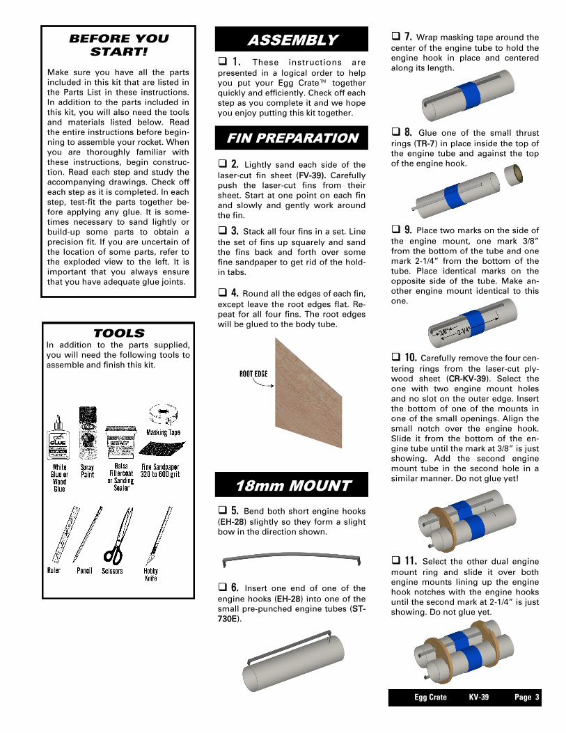
TOOLS In addition to the parts supplied,
you will need the following tools to
assemble and finish this kit.
BEFORE YOU START!
Make sure you have all the parts
included in this kit that are listed in
the Parts List in these instructions.
In addition to the parts included in
this kit, you will also need the tools
and materials listed below. Read
the entire instructions before begin-
ning to assemble your rocket. When
you are thoroughly familiar with
these instructions, begin construc-
tion. Read each step and study the
accompanying drawings. Check off
each step as it is completed. In each
step, test-fit the parts together be-
fore applying any glue. It is some-
times necessary to sand lightly or
build-up some parts to obtain a
precision fit. If you are uncertain of
the location of some parts, refer to
the exploded view to the left. It is
important that you always ensure
that you have adequate glue joints.
1. These instructions are
presented in a logical order to help
you put your Egg Crate™ together
quickly and efficiently. Check off each
step as you complete it and we hope
you enjoy putting this kit together.
ASSEMBLY
2. Lightly sand each side of the
laser-cut fin sheet (FV-39). Carefully
push the laser-cut fins from their
sheet. Start at one point on each fin
and slowly and gently work around
the fin.
3. Stack all four fins in a set. Line
the set of fins up squarely and sand
the fins back and forth over some
fine sandpaper to get rid of the hold-
in tabs.
4. Round all the edges of each fin,
except leave the root edges flat. Re-
peat for all four fins. The root edges
will be glued to the body tube.
FIN PREPARATION
18mm MOUNT
5. Bend both short engine hooks
(EH-28) slightly so they form a slight
bow in the direction shown.
10. Carefully remove the four cen-
tering rings from the laser-cut ply-
wood sheet (CR-KV-39). Select the
one with two engine mount holes
and no slot on the outer edge. Insert
the bottom of one of the mounts in
one of the small openings. Align the
small notch over the engine hook.
Slide it from the bottom of the en-
gine tube until the mark at 3/8” is just
showing. Add the second engine
mount tube in the second hole in a
similar manner. Do not glue yet!
8. Glue one of the small thrust
rings (TR-7) in place inside the top of
the engine tube and against the top
of the engine hook.
7. Wrap masking tape around the
center of the engine tube to hold the
engine hook in place and centered
along its length.
6. Insert one end of one of the
engine hooks (EH-28) into one of the
small pre-punched engine tubes (ST-
730E).
9. Place two marks on the side of
the engine mount, one mark 3/8”
from the bottom of the tube and one
mark 2-1/4” from the bottom of the
tube. Place identical marks on the
opposite side of the tube. Make an-
other engine mount identical to this
one.
11. Select the other dual engine
mount ring and slide it over both
engine mounts lining up the engine
hook notches with the engine hooks
until the second mark at 2-1/4” is just
showing. Do not glue yet.

Page 4 S Egg Crate KV-39
24mm MOUNT
22. Apply glue to the root edge of
one of the fins and position it along
one of the lines drawn for the fins on
the side of the body tube and even
with the bottom. Do not use the LL
line. Remove the fin, set it aside and
allow it to almost dry, apply addi-
tional glue, and reposition. Repeat
for the other three fins. If you follow
these instructions, the fins will not
require much additional work to keep
them aligned. Allow the fins to com-
pletely dry, checking carefully to
make sure they are parallel with the
main body tube.
FINS
23. Apply a thick bead of glue on
one side of the basswood strip (FV-
39S). Glue it on the inside of the
main body tube over one of the fins
and 1/4” from the bottom of the tube.
Make sure it is parallel with the main
body tube. Wipe any excess glue
from the exposed edges.
12. Using the small basswood
strip (FV-39S) as a gauge, test the
spacing between the rings. They
should almost touch both ends of the
strip all around the mount. Adjust the
rings, if necessary, and apply glue at
the intersection of the tubes and
rings, keeping glue away from the
outer surfaces of the rings and away
from the engine hook slot on the bot-
tom ring. Apply a bead of glue over
the masking tape at the area over
each engine hook. Allow to dry,
while checking the fit with the bass-
wood strip.
14. Insert one end of the long
engine hook (EH-38) into the large
pre-punched engine tube (ST-940E).
18. Select the remaining ring with
no slot on the outer edge. Align the
small notch over the engine hook.
Slide it from the bottom of the en-
gine tube until the mark at 3/8” is just
showing. Do not glue yet.
16. Glue the large thrust ring (TR-
9) in place inside the top of the en-
gine tube and against on top of the
engine hook.
15. Wrap masking tape around
the engine tube about 1” from the
bottom to hold the engine hook in
place and centered along its length.
17. Place two marks on the side
of the engine mount, one mark 3/8”
from the bottom of the tube and one
mark 2-1/4” from the bottom of the
tube.
13. Bend the long engine hook
(EH-38) slightly so it forms a slight
bow in the direction shown.
19. Select the last ring and slide it
over the top of the engine mount
with the small notch aligned over the
engine hook until the second mark at
2-1/4” is just showing. Do not glue
yet.
20. Using the small basswood
strip again, test the spacing between
the rings. They should almost touch
both ends of the strip all around the
mount. Adjust the rings, if necessary,
and apply glue at the intersection of
the tube and rings, keeping glue
away from the outer surfaces of the
rings and away from the engine hook
slot on the bottom ring. Apply a bead
of glue over the masking tape at the
area over the engine hook. Allow to
dry, checking the fit with the bass-
wood strip.
MARK THE TUBE
21. Stand the large body tube (ST
-16120) on the fin guide below. Place
five marks on the tube at the posi-
tions indicated. Place a mark LL on
the line that will be used for the
launch lug. Find a convenient chan-
nel or groove such as a partially
open drawer, a door jamb (as
shown,) or a piece of molding. Using
the channel, extend all the marks the
full length of the tube.
Egg Crate KV-39 Page 5
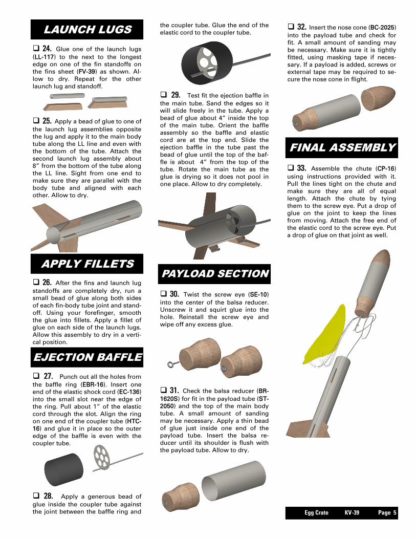
24. Glue one of the launch lugs
(LL-117) to the next to the longest
edge on one of the fin standoffs on
the fins sheet (FV-39) as shown. Al-
low to dry. Repeat for the other
launch lug and standoff.
LAUNCH LUGS
26. After the fins and launch lug
standoffs are completely dry, run a
small bead of glue along both sides
of each fin-body tube joint and stand-
off. Using your forefinger, smooth
the glue into fillets. Apply a fillet of
glue on each side of the launch lugs.
Allow this assembly to dry in a verti-
cal position.
APPLY FILLETS
33. Assemble the chute (CP-16)
using instructions provided with it.
Pull the lines tight on the chute and
make sure they are all of equal
length. Attach the chute by tying
them to the screw eye. Put a drop of
glue on the joint to keep the lines
from moving. Attach the free end of
the elastic cord to the screw eye. Put
a drop of glue on that joint as well.
FINAL ASSEMBLY
25. Apply a bead of glue to one of
the launch lug assemblies opposite
the lug and apply it to the main body
tube along the LL line and even with
the bottom of the tube. Attach the
second launch lug assembly about
8” from the bottom of the tube along
the LL line. Sight from one end to
make sure they are parallel with the
body tube and aligned with each
other. Allow to dry.
PAYLOAD SECTION
31. Check the balsa reducer (BR-
1620S) for fit in the payload tube (ST-
2050) and the top of the main body
tube. A small amount of sanding
may be necessary. Apply a thin bead
of glue just inside one end of the
payload tube. Insert the balsa re-
ducer until its shoulder is flush with
the payload tube. Allow to dry.
32. Insert the nose cone (BC-2025)
into the payload tube and check for
fit. A small amount of sanding may
be necessary. Make sure it is tightly
fitted, using masking tape if neces-
sary. If a payload is added, screws or
external tape may be required to se-
cure the nose cone in flight.
30. Twist the screw eye (SE-10)
into the center of the balsa reducer.
Unscrew it and squirt glue into the
hole. Reinstall the screw eye and
wipe off any excess glue.
EJECTION BAFFLE
27. Punch out all the holes from
the baffle ring (EBR-16). Insert one
end of the elastic shock cord (EC-136)
into the small slot near the edge of
the ring. Pull about 1” of the elastic
cord through the slot. Align the ring
on one end of the coupler tube (HTC-
16) and glue it in place so the outer
edge of the baffle is even with the
coupler tube.
28. Apply a generous bead of
glue inside the coupler tube against
the joint between the baffle ring and
29. Test fit the ejection baffle in
the main tube. Sand the edges so it
will slide freely in the tube. Apply a
bead of glue about 4” inside the top
of the main tube. Orient the baffle
assembly so the baffle and elastic
cord are at the top end. Slide the
ejection baffle in the tube past the
bead of glue until the top of the baf-
fle is about 4” from the top of the
tube. Rotate the main tube as the
glue is drying so it does not pool in
one place. Allow to dry completely.
the coupler tube. Glue the end of the
elastic cord to the coupler tube.

Page 6 S Egg Crate KV-39
34. When the fillets have dried,
prepare balsa surfaces for a smooth
professional looking finish. Fill the
wood grain with balsa fillercoat or
sanding sealer, When dry, sand with
fine sandpaper. Repeat until smooth.
FINISHING
35. After all balsa surfaces have
been prepared, wipe off all balsa
dust with a dry cloth. First spray the
model with an enamel primer.
Choose high visibility colors like
white and black for the final color.
36. Spray painting your model
with a fast-drying enamel will pro-
duce the best results. PATIENCE…is
the most important ingredient. Use
several thin coats, allowing each coat
to completely dry before the next
coat. Start each spray a few inches
above the model and end a few
inches below the model. Keep the
can about 12” away and use quick
light coats. The final coat can be a
little heavier to give the model a
glossy wet-looking finish.
FLIGHT PREPPING
43. Carefully check all parts of
your rocket before each flight as a
part of your pre-flight checklist.
Launch the Egg Crate™ from a 1/8”
diameter by 36” long launch rod.
40. Mounting the engines: When
flying with the 24mm adapter and
the length of the engine is 3.75”, it
will work directly. If the engine is the
shorter 2.75” length, you must insert
a spacer (HTC-9) ahead of the engine.
Insert the engine and make sure the
engine hook keeps the engine in
snugly. The hook may be slightly
bent to make sure the engine is re-
tained. When flying with the dual
18mm engines, make sure both en-
gines are the same impulse and de-
lay and the engine hooks capture the
engines snugly.
41. Although a baffle is used, it is
always good to apply a few sheets of
recovery wadding in the top of the
main body tube. If you are flying a
payload, the included parachute may
not be large enough. Adding a sec-
ond parachute chute will slow the
recovery. Fold the parachute and
pack it and the shock cord on top of
the recovery wadding. Slide the pay-
load section into place, making sure
it does not pinch the shock cord or
parachute.
37. After the paint has dried, de-
cals should be applied. The decals
supplied with the Egg Crate™ are
waterslide decals. Each decal should
be cut separately from the sheet.
Think about where you want to apply
each decal and check for fit before
wetting the decal. Use the cover
photo for suggested placement. Dip
each decal in a small dish of water
that has a drop of detergent. It will
take about 30 seconds before the
decal is loose enough to apply. The
egg shaped decals have a white
background and should be cut just
inside the outside black border.
38. Slide the decal in place and
use the paper backing to work the
bubbles out. Repeat for all the de-
cals.
44. After each flight, promptly
remove the spent engine casing or
casings and dispose of properly. Re-
move the interchangeable mount
and clean any residue.
42. Refer to the model rocket en-
gine manufacturer’s instructions to
complete the engine prepping. Differ-
ent engines have different igniters
and methods of hooking them up to
the launch controllers. Always use at
least a 12-volt system in top condi-
tion when launching with the dual
mount. The lead wire should be at
least 16 gauge or less and no more
than 20 feet in length. Make sure all
connections are tight and the electri-
39. The Egg Crate™ has two inter-
changeable engine mounts. If you
are flying with 24mm engines, insert
the 24mm mount as shown. Align
the slot in the top ring and align it
with the basswood strip. Push for-
ward until the bottom ring touches
the basswood strip, then rotate the
mount 180 degrees. If it is tight,
check for excess glue or the plywood
rings being less than 1-3/4” from
each other. The dual 18mm mount
inserts in a similar fashion.
cal system is in perfect order. A full
tutorial on clustering is outside the
scope of these instructions. If you are
not experienced with clustering, a
search online will yield many tutori-
als to get you started on one of the
most challenging propulsion meth-
ods for model rocketry.