
Abbott Pain Manager II - InfuSystem APMII.pdf · 0 A 0 iv System Operating Manual. ... Guide to...
57
6/05) 430X00032-001 (Rev. 13965-04 This manual is designed for use by healthcare professionals, caregivers, and patients. The Abbott Clinical Customer Support hotline is available 24 hours a day to provide consultation and technical assistance regarding the APM II. Abbott Clinical Customer Support l-800-338-7867 To order additional copies of this manual (List No. 13254-01) call I-800-ABBOTT3 Abbott Pain Manager II System Operating Manual For use with List
Transcript of Abbott Pain Manager II - InfuSystem APMII.pdf · 0 A 0 iv System Operating Manual. ... Guide to...

6/05)430X00032-001 (Rev.
13965-04
This manual is designed for use by healthcare professionals,caregivers, and patients. The Abbott Clinical Customer Supporthotline is available 24 hours a day to provide consultation andtechnical assistance regarding the APM II.
Abbott Clinical Customer Supportl-800-338-7867
To order additional copies of thismanual (List No. 13254-01) call
I-800-ABBOTT3
Abbott Pain Manager II
System Operating Manual
For use withList

6/05)430-600032-001 (Rev.
.2-10..................
....................2-10
Using the Carrying Case
Lockbox ...................... 2-9
Using the Pole Clamp
.................. 2-8
Using the
.................. 2-7
Purging the Complete Set
..... 2-6Loading the Cartridge
................. 2-5Attaching the Anti-Siphon Valve Extension Set
....... 2-4Gravity Priming the Set
............. 2-4
Preparing the Cartridge Set and Container
............... 2-3
Cartridge Set and Container Setup
............ 2-3Connecting the Bolus Cord
................ 2-2Connecting the AC Power Supply
.............. 2-1Installing the Battery Pack
........... 2-1
installing Disposable Batteries
....................... 2-1Power Source(s) and Bolus Cord Setup
0 Setup
................... l-5
.................. 1-4
Warnings and Cautions
...................... 1-4
Contraindications for Use
.................... 1-3
Indications for Use
APMTM II Accessories
............. l-3Quick-Loadm Pump Set
........................vi
Introduction ................... l-1The Abbott
............................ ii
Change History.
a
Contents
Warranty

6105)430-600032-001 (Rev.
................. 5-3
.............. 5-3
Printing the Program History
............... 5-3
Displaying the Amounts Delivered
............. 5-l
Displaying the History Event Log
................. 5-I
History Review Tips and Information
....... 4-10
Program History
..................... 4-8
Locking the Keypad ................... 4-9
Unlocking the Keypad .................. 4-9
Activating the Automatic Keypad Lock .......... 4-9
Deactivating the Automatic Keypad Lock
................. 4-7
Locking the Keypad
..................... 4-6
Changing the Air Sensitivity
................ 4-6
Changing the Clock.
................... 4-5
Displaying the Date and Time
.................... 4-5
Entering a New Program
.................... 4-4
Repeating the Program
.................... 4-4
Changing the Program
.............. 4-3
Reviewing the Program
.............. 4-3
Clearing Amounts at Start of Shift
.................. 4-2
Delivering a Bolus (or PCA) Dose
....................... 4-l
Delivering a Loading Dose
....................... 4-l
Stopping delivery
.................... 4-1Starting delivery
................... 3-3
Operation
.................... 3-2
Programming the Pump
.............. 3-l
Turning On the APM II
.................. 3-1
Programming Tips and Information
0
Programming
A0
0
iv System Operating Manual

2/96)43MOO032-A01 (Rev.
. 9-9
.................... 9-2
Abbott Pain Manager II (APM TM II) Installation Test Record
...................... 9-l
Operation Verification
................. 9-1Physical Inspection
@ Installation Test
8-1.. . . . . . . . . . . . . . . . . 0 Specifications
...................... 7-8.................... 7-6
System Alarm
.................. 7-6
Malfunction Alarm
...................... 7-5
Purge Overuse Alarm
..................... 7-5
Power Alarms
..................... 7-4
Air-in-Line Alarm
................. 7-4
Occlusion Alarm
................... 7-3
Check Cartridge Alarm
....................... 7-3
Check Printer Alarm
................... 7-3
Empty Alert
................. 7-2
Almost Empty Alert
................. 7-2
1 and 4 Hour Limit Alert
................. 7-2
Call Back or Start Alert
................. 7-2
Amount Too Small Alert
................. 7-2
Amount Too Large Alert
................. 7-1
Guide to Alerts and Alarms
...................... 7-l
Displaying Software Version
7-l
Customer Support
.................1c
U Alerts & Alarmsn
............................ 6-4...................... 6-4
Repair
............... 6-3
Functional Testing
................... 6-3
Storage and Memory Protection
..................... 6-2
Battery Pack Recharging
.................. 6-l
Cleaning the Optics
................... 6-1
Cleaning and Disinfection
Maintenance

2/96)43CMI0032-A01 (Rev.
toloading dose; add notes regarding 3-6, Sectiondelivery of bolus and loading doses 9, back coverwith hour limit set; add Section 9,Installation Test; add CE Mark
Pages Changed
l-3,3-4 2/96)
Original Issue
Correct bolus cord list number; add Cover, v, vi,note regarding priming before starting
430-600032-A01(Rev.
6/95)
0 Change History
System Operating Manual
Pat? Number Description of Change
430-600032-001(Rev.
vi

6/05)430-600032-001 (Rev.
lockbox, pole clamp, and carrying case are available asaccessories to allow the pump to be mounted on an IV pole or carriedover a shoulder or around the waist.
The figure on the next page shows the APM II’s operating controls.
(pg).
A loading dose may be set for delivery during programming, whenprogrammingis complete, or after the pump is started. Programmedbolus (or PCA) doses are delivered using the bolus cord.
A keypad lock option is available to control access to pump functions.Safety features include built-in alarms for an improperly installedcartridge, air or occlusion in the line, low power, and devicemalfunction. For a complete list of alerts and alarms, go to Section7, Alerts and Alarms.
The pump maintains a timed history of each event (for example,bolus requests made and delivered) and any alarms that may occurthat can be reviewed on the screen or printed.
The APM II has three power source options: two disposable 9-Vbatteries, an AC power adapter, or a rechargeable snap-in batterypack. A
(mg), or micrograms (mL),
milligrams
(mIJhr), continuous withbolus, or bolus only
Three programming options are available:
ContinuousBolus or PCA OnlyBoth Continuous and Bolus or PCA
The APM II infuses in three units of delivery: milliliters
(APMTM II) is a single-channel infusionpump that delivers analgesia to patients in the hospital, inoutpatient treatment centers, and in the home.
The pump is designed for pain management protocols, e.g., epidural,Patient Controlled Analgesia (PCA), and can also be used for othertherapies that require infusion delivery schedules of continuousrates at or below 25 milliliters per hour
0 Introduction
The Abbott Pain Manager II

6/05)
than
l Press and hold topurge the pump
LOADING DOSEl Enters and delivers a
loading dose
UP and DOWN arrowsl Scroll through history logl Up arrow enters decimal
l Accepts values enteredduring programming
l Access various operatingfeatures
YES and NOl Respond to questions during programming
ON/OFFl Turns the power on or off
430-600032-001 (Rev.
1-2 System Operating Manual
SILENCEl Silences various alarms
RUN/STOPl Starts or stops delivery
HISTORYl Accesses program, shift, and container information
l Prints program, shift, andcontainer information
during programming
REVIEW/CHANGEl Reviews and

2/96)43~600032-A01 (Rev.
mL or smaller container of solution and the APMII pump with batteries or battery pack installed.
APMTM II Accessories
These accessories are available for use with the APM II:
AC Power Supply, List 13036Powers the APM II. Do not use the power supply with otherproducts.Battery Pack System, List 13886
Two rechargeable Battery Packs and the Battery Charger.Battery Pack, List 13887Powers the APM II pump during periods of ambulation or whenuse of AC power is not desirable.Battery Charger, List 13888Charges the Battery Pack.Bolus Cord, List 13701Allows bolus requests to be made up to 6 feet away from the pump.Carrying Case, List 13959Carries a 250
‘Ib use an AbbottQuick-Load set, follow directions included with the set.
Cl
* Patient access device
Accessories such as air eliminating filters and extension sets maybe added to the line as required by the therapy.
13580), which is a sterile, single-use, disposable set.
Contact an Abbott Laboratories representative for appropriate setconfiguration. The minimum elements required for use with theAPM II pump include one of each of the following:
l Non-vented, collapsible fluid containerl Abbott Quick-Load pump set
Quick-LoadTM set (e.g.,List No.
0 The Abbott Quick-Load” Pump Set
The APM II can be operated with an Abbott
APM II Introduction 1-3

6/95)
USP, Lidocaine Hydrochloride USP) and analgesicdrugs (e.g., Morphine Sulfate Injection, Preservative-Free USP) canbe administered epidurally through recommendedwithout Y-injection sites.
device sets
Cl Contraindications for Use
The pump should not be used by patients who do not have the mentaland physical capability or emotional stability to receive infusiontherapy with this device. Physicians or certified, licensed healthcareprofessionals should always oversee therapy Drugs not compatible
430-600032-001 (Rev.
0 Indications for Use
The pump is suitable for intravenous (central line or peripheralaccess), arterial, subcutaneous, and epidural infusion. Pump usersshould be under the supervision of a healthcare professional andshould be instructed in using and troubleshooting the pump.Instruction should emphasize preventing related IV complications,including appropriate precautions to prevent accidental infusion ofair. The epidural route can be used to provide anesthesia oranalgesia. Approved anesthetic drugs (e.g., ChloroprocaineHydrochloride
& 180si printersAllows the event history log to be printed.
150+ Diconix*
Lockbox.Pole Clamp, List 13230Attaches the pump to an IV pole.Pole Clamp Adapter, List 13728Printer Cables, Lists 13007 and 1300813007 for Seiko’ DPU411 printer13008 for Kodak
Lockbox Key, List 13387Replacement key for
prealed syringe. Access is provided for connectionof bolus cord, AC Power Supply, and printer.
mL Abbott mL or smaller container of solution or
30
Lockbox, List 13955Secures the pump and 250
I-4 System Operating Manual
6/05)43CMOOO32-001 (Rev.
affected byunintended operations and failures, including interruptedmedication or fluid delivery from the device, close supervision andprovision for immediate corrective action should be provided.
Regarding Drugs Used, Cartridge Sets, and Containers:
Never use drugs that are incompatible with silicone rubber orPVC plastic.To reduce loss of potency for drugs known to be absorbed byplastic and silicone, begin infusion as soon as practical afterpriming the set. Use of high flow rates during infusion willminimize drug absorption.Do not use medications which are unstable under infusionconditions.Always use connections with luer lock fittings.Use aseptic technique with all fluid path connections. Remove theprotective coverings as assembly progresses.
Always close the slide clamps before removing the cartridge fromthe pump.
0 Warnings and Cautions
The following is a list of warnings and cautions that should beheeded when operating the APM II. Attention should be given to allalert messages.
General:
Federal (USA) law restricts this device to sale by or on the orderof a physician or other licensed practitioner.Manual references to specific values are approximate only unlessindicated otherwise. Air-in-line sensitivity values areapproximate only.For those patients who are likely to be adversely
Tom anIV pole and used with a Universal Adapter Pin (List 17015-48).
APM II Introduction 1-5
with silicone rubber or PVC plastic, or not stable under infusionconditions should not be used with this system. The drug reservoirshould preferably be a nonvented, collapsible container or syringe.If a vented fluid container is used, it should be suspended

6/95)
PI
430-600032-001 (Rev.
- Epidural stickers for the pump indicating ongoing epiduraladministrationEpidural administration of drugs should be limited to medicalprofessionals familiar with associated techniques and patientmanagement problems. Proper epidural placement of thecatheter is essential since catheter migration could result inintravascular or intrathecal administration. Facilities practicingepidural administration must be equipped with resuscitativeequipment, oxygen, naloxone, and other resuscitative drugs.Adequate monitoring equipment (e.g., Oximetry), isrecommended for continuous monitoring of the patient duringepidural administration. Patients must be observed for sideeffects frequently in a fully equipped and staffed environment forat least 24 hours following completion of drug administration bythe epidural route.
- Pump sets without Y-sites- Nylon or Teflon@ catheter
unless suspended from a pole and a Universal Adapter Pin, ListNo. 17015-48, is in place.
Regarding Air-In-Line and Infusion:
l Stop infusion if signs or symptoms of infiltration occur.l To reduce the risk of infusing air, use an air-eliminating filter
when the air-in-line alarm is off.
l Always remove all air from the cartridge, tubing and injectionsite. Always disconnect the set from the patient prior to priming.
Regarding Epidural Administration
The epidural route is recommended to provide anesthesia oradminister analgesia for periods up to 96 hours.For epidural use, the administration of drugs is restricted to thoseanesthetic and analgesic drugs approved for continuous epiduraladministration: Chloroprocaine Hydrochloride USP, LidocaineHydrochloride USP and Morphine Sulfate Injection USP,(Preservative Free).For epidural administration, the following is recommended:
I-6 System Operating Manual
l Arrange tubing, cords, and cables to minimize the risk of patientstrangulation or entanglement.
l Never use vented fluid containers (e.g., glass or rigid plastic)

6/05)43@600032-00 1 (Rev.
high intensity electromagnetic radiation(e.g., radio transmitters, MRI scanners, microwave ovens, X-raymachines, and CAT scanners).Possible explosion hazard exists if used in the presence offlammable anesthetics. Never use the pump in the presence offlammable or explosive vapors.Nonhazardous, low-level electrical potentials are commonlyobserved when fluids are administered using infusion devices.These potentials are well within accepted safety standards, butmay create artifacts on voltage sensing equipment such as ECG,EMG and EEG machines. These artifacts vary at a rate that isassociated with the infusion rate. If the monitoring machine isnot operating correctly or has loose or defective connections to its
g-volt Duracell@ alkaline batteries. Installing batteries isrecommended, regardless of the power source used, to providecontinuing operation if AC power fails. Always replace bothbatteries with new batteries when a change is required.Always avoid sources of
supply.Do not use non-Abbott AC power supplies with the APM II as thismay result in damage to the pump’s circuitry.Pump performance may vary with use of batteries other than
I-7
WARNING: Delayed respiratory depression followingcontinuous epidural administration of preservative-freemorphine sulfate has been reported.The epidural space has 58 openings through which fluid can exit.Pressure buildup during administration is transient. However, ifa large volume of fluid is administered over a short time period,the pressure takes longer to return to normal. If over-deliveryoccurs during administration, observe the patient closely forcompression on the spinal cord (disorientation, headache,transient neuralgias) and drug overdose.Epidural administration of anesthetics is limited to thecontinuous mode only.Epidural administration of analgesics may be delivered bycontinuous, bolus, or continuousibolus.
Regarding Pump Operation:
If the pump does not perform as stated in this manual, removefrom service immediately.Always connect to grounded AC outlet when using the AC power
APM II Introduction

6/95)43O-6OOCB2-001 (Rev.
dimethyl benzyl ammonium chloride.Do not sterilize by heat, steam, ETO, or radiation. Applydisinfectants to the outside surface of the pump only. Do not useabrasive cleaners or materials on the pump. Using abrasivecleaners or cleaning solutions not recommended by AbbottLaboratories may result in product damage.Use only the AC power supply delivered with the APM II tocharge the battery pack.Always remove batteries if pump is to be stored for an extendedperiod of time.
confirm no damage has occurred.Always avoid dropping or hitting the pump. If the pump isdropped or hit, always verify programmed data.Never use sharp objects (e.g., fingernails, pens, pencils or otherprobes) to program or clean the pump.To avoid mechanical or electronic damage, never submerge pumpin water or other fluids and avoid fluid spills. If pump becomeswet, dry it immediately. Check connections and programmeddata.Some cleaning and sanitizing compounds may slowly degradecomponents made from some plastic materials. Do not usecompounds containing combinations of isopropyl alcohol and
1-8 System Operating Manual
sensing electrodes, these artifacts may be accentuated so as tosimulate actual physiological signals. To determine if theabnormality in the monitoring equipment is caused by theinfusion device instead of some other source in the environment,set the infusion device so that it is temporarily not deliveringfluid. Disappearance of the abnormality indicates that it wasprobably caused by electronic noise generated by the infusiondevice. Proper setup and maintenance of the monitoringequipment should eliminate the artifact. Refer to the appropriatemonitoring system documentation for setup and maintenanceinstructions.
Regarding Handling and Maintenance:
Product damage may occur if proper care is not exercised duringunpacking, installation, and use. Should the pump inadvertentlybe subjected to mishandling, check connections and programmeddata to

6/95)43MOOO32-001 (Rev.
P-P.l Insert two 9-V batteries into the compartment; be sure the
positive and negative battery terminals are placed according tothe diagram in the battery compartment.
l Replace the battery door.
Two (2)9 Volt Batteries
!III install batteries, complete the following steps:
l Turn the pump off and remove the battery door on the back of the
0 Power Source(s) and Bolus Cord Setup
Install batteries, the battery pack, or the AC power supply beforeusing the APM II. If bolus or PCA delivery is desired, connect thebolus cord.
0 Installing Disposable Batteries
lockbox, pole clamp, and carrying case-
- batteries, battery pack, and AC power supplyBolus cordCartridge set and containerAccessories
Q Setup
This section describes how to set up the following elements of theAPM II system:
Power sources

6/05)
III remove the pack, rotate its knob counter-clockwise and slide thepack out.
For charging instructions, go to page 6-3, Battery Pack Recharging.
Open and lock knob
430-600032-001 (Rev.
‘III install the battery pack, complete the following steps:
l Remove the battery compartment door.l Remove the disposable batteries, if installed.l Slide the battery pack into the battery compartment.l While pressing the battery pack in place, rotate its knob clockwise
to lock it into position.
2-2 System Operating Manual
CAUTION: To assure proper pump operation, always replace bothbatteries with fresh alkaline batteries when a change is required.
Installing batteries is recommended regardless of the power sourceused to provide continuing operation if AC power fails.
0 Installing the Battery Pack

6/95)
Tb connect the bolus cord, insert the pin connector into the port onthe pump.
430-600032-001 (Rev.
volt).
CAUTION: Always connect to grounded AC outlet when using the ACpower supply.
WARNING: Use of power adapters other than Abbott approvedpower adapter could damage the internal electroniccomponents of the device which may cause a malfunction ofthe device.
0 Connecting the Bolus Cord
iUPPlY
0 Connecting the AC Power Supply
‘Ib connect the AC power supply, complete the following steps:
l Insert the pin connector into the port on the bottom of the pump.l Plug the AC power supply into a standard wall outlet (grounded
110
B
APM II Setup 2-3

6/95)430-6OOQ32-001 (Rev.
I
0
0
0
Open the delivery set packageand remove the contents.
If using a cartridge set with ananti-siphon valve extension,separate the cartridge set andextension set and return theextension set to the package.
Loosen, but do not remove, theprotective cover from the distalmale adapter.
Confirm that the cartridge is inthe open position with the dotinside the parallel lines.
The cartridgeallow fluid totubing.
must be open toflow through the
-
0 Cartridge Set and Container Setup
Before programming the pump, prepare the cartridge set andcontainer for delivery, gravity prime the set, attach the anti-siphonvalve extension set (if required), and load the cartridge in the pump.
CAUTION: To prevent contamination, use aseptic technique with allfluid path connections. Remove protective coverings as assemblyprogresses.
0 Preparing the Cartridge Set and Container
2-4 System Operating Manual
6/05)430600032-001 (Rev.
APM II Setup 2-5
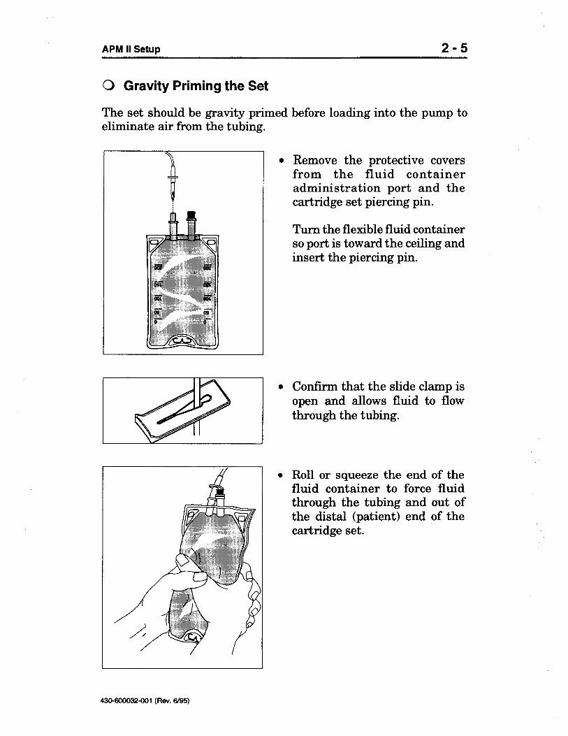
0 Gravity Priming the Set
The set should be gravity primedeliminate air from the tubing.
before loading into the pump to
0 Remove the protective coversfrom the fluid containeradministration port and thecartridge set piercing pin.
Turn the flexible fluid containerso port is toward the ceiling andinsert the piercing pin.
0 Confirm that the slide clamp isopen and allows fluid to flowthrough the tubing.
l Roll or squeeze the end of thefluid container to force fluidthrough the tubing and out ofthe distal (patient) end of thecartridge set.

6/95)
Confirm the dot is inside of thered circle.
l Close the slide clamp.
0 Attaching the Anti-Siphon Valve Extension Set
0
Distal maleadapter
l
Remove anti-siphon valveextension set from packaging.
Remove protective covers fromthe male connector on thecartridge set and theanti-siphon valve extension set,then aseptically connect twosets.
Confirm that the slide clamp onanti-siphon valve extension setis open.
430-600032-001 (Rev.
2-6 System Operating Manual
l Turn the control knob on thecartridge to the closed position.

6/95)43MOOO32-001 (Rev.
Confirm the cartridge is closed(dot is inside the red circle).
Align the cartridge to fit theshape of the cartridge channel.The tab labeled DO NOTREMOVE should be to the leftand the rotor should bepositioned over the motor shaft.
Push cartridge into cartridgechannel until firmly seated.
Close the pump latch by slidingthe latch down, in and up.
Confirm that the cartridge islocked into place.
APM II Setup 2-7
0 Loading the Cartridge
Open the pump latch by slidingthe latch down, then out.
6/95)
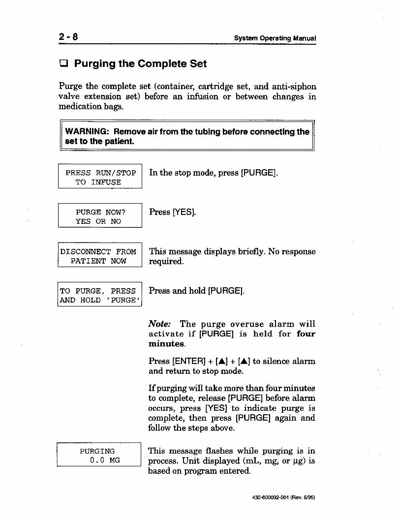
pg) isbased on program entered.
430-600032-001 (Rev.
(mL, mg, or
0 Purging the Complete Set
Purge the complete set (container, cartridge set, and anti-siphonvalve extension set) before an infusion or between changes inmedication bags.
WARNING: Remove air from the tubing before connecting theset to the patient.
In the stop mode, press [PURGE].
Press [YES].
I 1DISCONNECT FROM
PATIENT NOWThis message displays briefly. No responserequired.
Press and hold [PURGE].
Note: The purge overuse alarm willactivate if [PURGE] is held for fourminutes.
Press [ENTER] + [A] + [A] to silence alarmand return to stop mode.
If purging will take more than four minutesto complete, release [PURGE] before alarmoccurs, press [YES] to indicate purge iscomplete, then press [PURGE] again andfollow the steps above.
I IPURGING
0.0 MGThis message flashes while purging is inprocess. Unit displayed
2-8 System Operating Manual
6/05)430+00032-001 (Rev.
lockbox is secure on the IV pole when the door isopened.
lockbox to the IV pole with the pole clamp.
Confirm that the
lockbox door and lock with the key.Secure the
lockbox through the appropriate openings.Close the
lockbox. Confirm that the tubing and cords emergefrom the
lockbox.Note: Confirm the piercing pin and the tubing between thebag/syringe and the pump are not kinked. The pump signalsan occlusion only if the kink is between the pump and thepatient.Slide the pump with the installed cartridge from right to left inthe front of the
lockbox door with the key.Place the fluid bag or syringe in the back of the
lockbox, complete the following steps:
Open the
‘lb secure the pump in the
lockbox cannot secure the pump whilethe rechargeable battery pack is installed.
lockbox provides access to the remote bolus port, the AC powerport, and the printer port. The
lockbox to a vertical, round, or square IV pole 0.5-1.5 inches (1.3-3.8cm) in diameter.
The
lockbox door. A pole clamp attaches thelockbox secures the pump with the cartridge and fluid reservoir
in place. A key locks the
Lockbox
The
0 Using the
APM II Setup 2-9
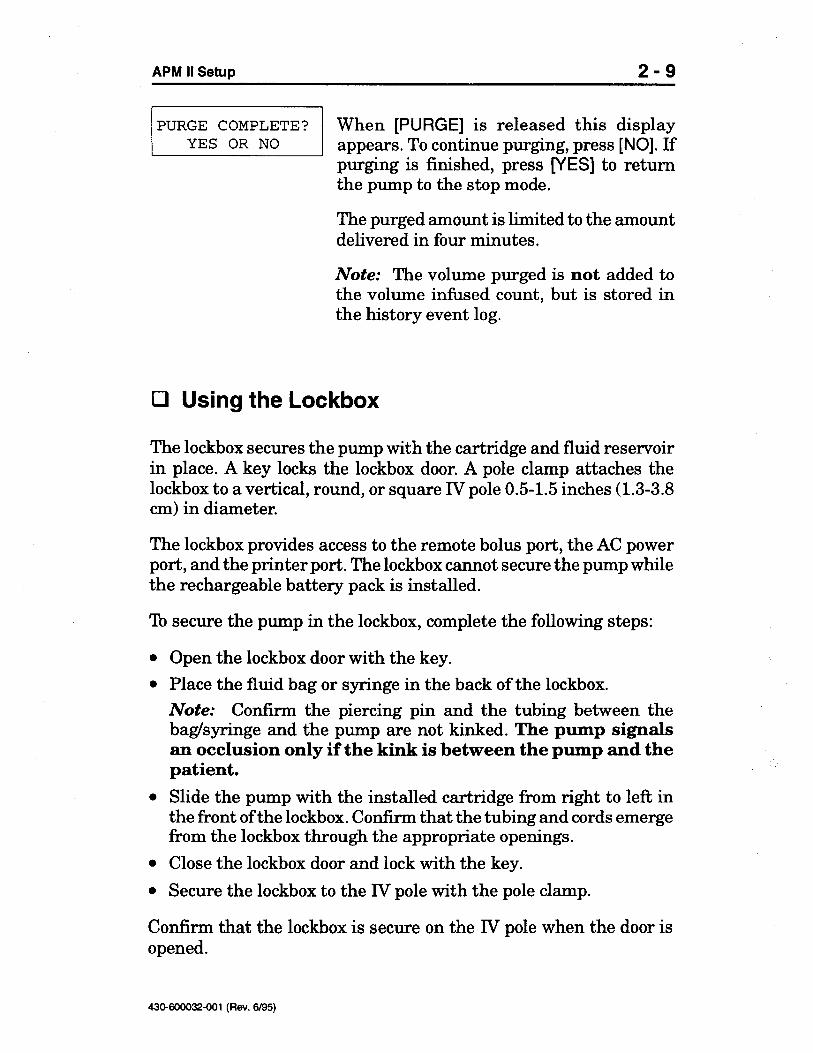
When [PURGE] is released this displayappears. To continue purging, press [NO]. Ifpurging is finished, press [YES] to returnthe pump to the stop mode.
The purged amount is limited to the amountdelivered in four minutes.
Note: The volume purged is not added tothe volume infused count, but is stored inthe history event log.

6/95)
To use the carrying case, proceed as follows:
Unzip the top of the case and release all Velcro@ straps.Place the pump and installed cartridge in the lid so the back ofthe pump faces up and the display screen is visible through theclear window of the case.Secure the wide straps across the width of the pump and securethe long black strap across the length of the pump.Release the black retaining straps.Open the Velcro pocket flap in the bottom of the case.Insert the fluid container with the spike connection on the openside of the pocket.Secure the Velcro pocket flap and secure the black retainingstraps over the pocket flap and the tubing in the Velcro tubingguides.Verify the patient side of the tubing and the remote bolus cord (ifconnected) emerges through the carrying case from the zippergap, then zip the case closed.
430-600032-001 (Rev.
left side of the backof the pump, then slide the pump onto the pole clamp.
0 Using the Carrying Case
The pump and the fluid bag can be placed in the carrying case fortransportation. The carrying case strap can be adjusted to carry thecase over a shoulder or around the waist.
Note: Confirm that the tubing between the fluid bag and the pumpis not kinked. The pump signals an occlusion only if the kinkis between the pump and the patient.
To attach the pump to the pole clamp, screw one half of the two piecepole clamp package into the large hole on the top
lockbox is not used, the pump can be secured to an IV pole byusing the pole clamp package.
0 Using the Pole Clamp
If a
2- 10 System Operating Manual

6/95)43MOOO32-001 (Rev.
x. The actual displays you willsee depend upon choices you make duringprogramming.
mL equivalent. The pumpmakes the calculation, then displays therounded value for confirmation.
Variable characters are shown in thismanual as
pg may be rounded downto the nearest 0.1
[ENTER]
to confirm that value.
AMOUNT TOO SMALLIf a value entered is too small, this messageflashes; the pump defaults to zero.
AMOUNT TOO LARGEIf a value entered is too large, this messageflashes; the pump defaults to zero.
ROUNDINGVolumes in mg or
[2] + [0] + [ENTER] to enter 20.
Press [A] to place a decimal point in anumeric value.
Press [RESET] before pressing [ENTER] toreturn an incorrect numeric value to zero.
About 5 seconds after selecting a numericvalue you will be reminded to press
A
'ENTER' IF DONE
Use the number keys to make valueselections and press [ENTER] to accept; e.g.,press
Ioi
0 Programming
0 Programming Tips and Information

6/95)
afier the self-test.
If the time or date are incorrect, programthe pump, then change the setting. Forinstructions, go to page 4-6, Changing theClock.
Press [YES] to clear and enter a newprogram and history or [NO] to keep thecurrent program and history.
If [NO] is pressed, the pump enters the stopmode. Press [RUN/STOP] to begin delivery.To retain history and enter a new program,refer to page 4-5, Entering a New Program.
If [YES] is pressed, this message appearsindicating the pump is clearing the programand history; no response required.
The previous program and history arecleared. The pump automatically advancesto the first programming screen.
If the keypad is locked and [YES] is pressedto clear the history, this message displaysbriefly. The pump automatically advancesto the stop mode. For information, refer topage 4-8, Locking the Keypad.
430-600032-001 (Rev.
(KEYPAD1
Press [ON/OFF] to power on the pump. Thepump begins a self-test. No responserequired.
The current program mode displays, if itwas not cleared before power-off.
The current time and date display forseveral seconds
I IUNIT SELF-TESTIN PROGRESS
0 Turning On the APM II
System Operating Manual3-2

6/95)43MiIOO32-001 (Rev.
mL, go to Step 5.mL programming, go to Step
4; for bolus only
mg/mL screen.
The unit selected carries through theremaining steps automatically.
For continuous
mL. Press[NO] to scroll back to
pg/mL. Press[NO] to scroll to next screen.
Press [YES] if programming in
mg/mL.Press [NO] to scroll to next screen.
Press [YES] if programming in
- Choose unit of delivery
Press [YES] if programming in
[3] to select type of delivery.
If PCA mode has been selected, the secondline will display 2 PCA ONLY.
Step 3
[2], or
- Choose type of delivery
Press [I],
- Choose delivery mode
Press [YES] to program in the epiduralmode. Press [NO] to advance to the PCAmode display screen.
Press [YES] to program in the PCA mode.
Step 2
APM II Programming 3-3
0 Programming the Pump
Step 1

2/96)430-600032-A01 (Rev.
[PRIME] key can be used to primethe set before [YES] is pressed to deliver theloading dose.
If [YES] is pressed, this display appears.Press [LOADING DOSE] to begin delivery.
The amount infused displays while delivery
deliveryimmediately. Press [NO] to hold the loading.
Note: The
fo;later dose c
&sired.
If [NO] is pressed, go to Step 6 for bolus orPCA programming or Step 7 for continuousprogramming.
Select the loading dose. Press [ENTER].
Press [YES] to begin loading dose
is dose -1Press [YES] or [NO] to indicate if a loading
- Program loading dose
xx/HR
Step 5
- Set continuous delivery rate
SET RATE Select the rate. Press [ENTER].x
press [ENTER].
For bolus only programming, go to Step 5.
Step 4
1 pg/mL.mg/mL or I’““““?% Select the concentration of
3-4 System Operating Manual

2/96)43MOO032-A01 (Rev.
pg). If [NO] is pressed to bypass the limitoption, this default remains active. Thisdefault limit can be raised or lowered byanswering [YES] to set a limit.
Note: A bolus in progress will not bestopped until the individual bolus volumehas been delivered, therefore, a bolusdelivery initiated before the programmedlimit has been reached may exceed the limitat the completion of the bolus.
Note: Loading doses are not included in thelimit volume and a limit in effect does notprevent a delivery of a loading dose.
mL is set (or equivalent in mg or
Press [ENTER].
If PCA mode has been selected, the pumpwilldisplay PCA LOCKOUT .
4 OR 1 HR LIMIT' Press [YES] to set a limit on the amount ofdrug the patient can be given in one or fourhours. If no limit is desired, press [NO] andgo to Step 7.
Note: In epidural mode, a default one-hourlimit of 25
71 Select the bolus lockout time (from 5 to 999).
pg). Press [ENTER].
If PCA mode has been selected, the pumpwilldisplay SET PCA DOSE.
(mL, mg, orJSETl
Select the bolus dose amount
- Program bolus or PCA dose
APM II Programming 3-5
When delivery is complete, go to Step 6 forbolus or PCA programming or Step 7 forcontinuous programming.
Step 6

2/96)43tMO0032-A01 (Rev.
[3] to select air alarmsensitivity setting.
The setting selected displays for severalseconds, then the pump saves the programand enters the stop mode.
Go to page 2-8, Purging the Complete Set, forinstructions.
CAUTION: To reduce the risk of infusing air, use an air-eliminatingfilter when the air-in-line alarm is off.
VI, or VI,
Off=airalarmoff.
Press
pL of air.
pL of air.
Low = alarm at approx. 300
- Select air sensitivity
High = alarm at approx. 100
- Program container size
Select the container size. Press [ENTER].
Note: Volume that is used when purgingthe pump with the [PURGE] key issubtracted from the container but is notadded to the amount infused.
Step 8
[4] to choose the length of limit.
Select the maximum volume (continuousplus bolus amount) that can be deliveredover a one-hour or four-hour period. Press[ENTER].
Step 7
] or [I
3=OFF
Press
2=LOW l=HI
3-6 System Operating Manual
AIR SENSITIVITY

6/95)430-600032-001 (Rev.
-1 In the run mode, press [RUN/STOP].
PRESS RUN/STOPTO INFUSE
The pump enters the stop mode.
0 Stopping delivery
(/) rotates while the pump is operating. Thetotal increases as the infusion continues.
xx/HR
In the stop mode, press [RUN/STOP].
The pump enters the run mode. A bar icon/RATE x
Operation
0 Starting delivery
Before starting an infusion, confirm the following:
All the set connections are secure.Air is removed from the container and the tubing.Slide clamps are open.Any clamps on the patient access device are open.
TOTAL x xx

6195)430-600032-001 (Rev.
- restart of infusion is not automatic if the loadingdose is delivered after the start of the program.
After the loading dose completes, press [RUN/STOP] to begindelivery again
‘Ib deliver the delayed loading dose, place the pump in the stop mode,press [LOADING DOSE], and follow the steps above.
> Delayed Loading Dose Delivery
If a loading dose is held for delivery during infusion, the user willnot be prompted again to deliver the loading dose.
xx/HR
In the stop mode, press [RUN/STOP]. If aloading dose is available, the followingmessage appears automatically.
Press [YES] to begin loading dose.
Press [NO] to hold the loading dose fordelayed delivery (see instructions below).
Press [LOADING DOSE] to begin delivery.
The amount infused displays while deliveryis in progress.
When the loading dose is complete, thepump automatically enters the run mode.
The dose amount is logged to the history andthe bolus lockout time is set (if applicable).Subsequent bolus requests are ignored untilthe lockout time has elapsed.
/RATE x
ITOTAL x xx
1
I
1
0 Delivering a Loading Dose
If a loading dose is set during programming and not delivered atthat time, it can be delivered at the start of the program or delayedfor delivery during infusion.
I IPRESS RUN/STOP
TO INFUSE
DEL. LOAD DOSEx xx
4-2 System Operating Manual

6195)43MCK1032-001 (Rev.
[I].
SHIFT RESET No response required. The pump returns tothe stop mode.
Note: When new shift totals are cleared,the Shift Information in the History EventLog is reset to zero; the program amountscontinue to accumulate.
Refer to page 5-2 for an example of theHistory Event Log.
0 Clearing Amounts at Start of Shift
PRESS RUN/STOPTO INFUSE
In the stop mode, press [RESET].
Press
shiR volumes and program volumes in the event history log and thebolus delivered count is incremented. When a bolus is requested thedemand count is incremented.
9311 start a bolus delivery, press the button on the end of the boluscord. The pump sounds three beeps and delivery begins, The amountinfused accrues as the delivery progresses.
If the bolus delivery does not start, it may be locked out by one ofthe following conditions:
l Bolus lockout period is in effect.l One-hour or four-hour amount limit is in effect.l Loading or bolus dose delivery already is in progress.
After a bolus is delivered, the amount is added to the totals in the
ODeration 4-3
Cl Delivering a Bolus (or PCA) Dose
APM II

6/95)
confIrmed the pump enters the stop mode.430-600032-001 (Rev.
confirmed to complete the change programfunction, After the air sensitivity setting is
1Press [I]. A screen listing the mode and typeof delivery displays briefly, followed by thefirst program parameter screen.
For each program parameter, the currententry displays or flashes. Press [ENTER]or indicated key, e.g., [YES], to acceptparameter as shown or change entries asdesired. Every parameter must be
12 NEW PROGRAM1 C HAN GE PROG RAM
[2].I:\Press
1 In the stop mode, press [REVIEW/CHANGE].‘“~~SRWW~T” /
[VI, or [HISTORY]. The pump returnsto the mode it was in when the review wasrequested.
0 Changing the Program
[v] to scrollback to the previous screen.
To end review, press any key other than[A],
from the run orstop mode to review the current program.
Press [I].
Press [A] or [HISTORY] to scroll through theprogram parameters. Press
a TO VIEW
Press [REVIEW/CHANGE]
0 Reviewing the Program
REVIEW COMPLETED
4-4 System Operating Manual

6/95)43MOOO32-001 (Rev.
/ For instructions,The pump enters the
Programming.
programming mode.Go to page 3-3,EP1~~?kl?~E
hSS[2].2 NEW PROGRAM
Press [YES] to clear the history, or press[NO] to clear only the current program.
[2].
1 CHANGE PROGRAM
[2].
No response required. The pump returns tothe stop mode.
0 Entering a New Program
PRESS RUN/STOP In the stop mode, press [REVIEW/CHANGE].TO INFUSE
1 REVIEW2 CHANGE
Press
0 Repeating the Program
In the stop mode, press [RESET].
Press
APM II Operation 4-5

6/95)
la-hour clockonly), and day of the week. Use the numberor arrow keys as indicated to make changes.Press [ENTER] to accept each screen.
The changed time and date briefly display,then the pump returns to the stop mode.
430-600032-001 (Rev.
la-hour display.
Use the arrows keys to select the month.Press [ENTER].
Screens appear for the day, year, hour,minute, AM or PM (for the
24-hour clock is desired.
Press [YES] for the 24-hour clock or [NO] toreturn to the
/ Press [YES] for the 12-hour clock or [NO] ifa
~~;F+URRL$K? [
[2].1 In the stop mode, press [ENTER], then '"~~sRRsT0" (
,batteries removed. The clock, however, needs adjusting for timezones or for daylight saving time changes.
I]
0 Changing the Clock
The clock operates up to one year with the power off or with the
[ 1 is pressed,
The display will remain active as long as 95 ;,
- 4 0 PMz:G
9 ZZ~ 1
hold [I].In the stop mode, press [ENTER], then press
and j ‘“~~“1~~~~‘“” 1 0 Displaying the Date and Time
4-6 System Operating Manual

6/95)43CMOOO32-001 (Rev.
YES OR NO [YES] to select LOW or [NO] to retain OFF.j If [NO] is pressed, this screen appears. Press
ALARM?
ALARM? YES OR NO Press [NO] to select LOW.
(LOW SENSITIVITY
I I
HIGH SENSITIVITY Press [YES] to select HIGH.
OR NO [YES] to select OFF or [NO] to retain LOW.
If current setting is OFF (no sensitivity):
ALARM? YES
[7].l Follow the steps below (determined by the current setting).l After a selection is made, the new setting displays briefly, then
the pump returns to the stop mode.
If current setting is HIGH sensitivity:
If [NO] is pressed, this screen appears. Press[YES] to select OFF or [NO] to retain HIGH.
If current setting is LOW sensitivity:
[YES] to select HIGH.[NO] to select OFF.
If [NO] is pressed, this screen appears. Press
0 Changing the Air Sensitivity
lb change the sensitivity setting, complete the following steps:
l Place the pump in the stop mode
l Press [ENTER], then
APM II Operation 4-7

6/95)
0 Locking the Keypad
Locking the keypad restricts access to programming, purging,clearing the event history log, and setting the clock.
For convenience, two types of keypad lock are available:
Keypad Lock
Allows the keypad to be locked and unlocked on an as neededbasis.
Automatic Keypad Lock
Requires the user to lock the keypad each time the pump is placedin the run mode. With this feature activated, the pump will notrun unlocked.The automatic lock may be a Full Lock or Container Lock, whichallows the container and shift to be reset.To access restricted functions, the user can unlock the keypad,but must reactivate the keypad lock before the pump will run.Deactivating the automatic lock is a separate step from unlockingthe keypad.
The following functions are available when the keypad is locked:
Turning the pump on or off.Starting or stopping the pump.Delivering a bolus (if available).Silencing an alarm.Displaying the date and time.Displaying software version and system error status.Displaying and printing the shift information, containerinformation, or history event log.Unlocking the keypad.With Container Lock only: all of the above plus resetting thecontainer and shift totals.
430-600032-001 (Rev.
4-8 System Operating Manual

6/95)43MOOO32-001 (Rev.
[2] to choose the type of lock.
[8].
Press [YES].
If [NO] is pressed the pump returns to thestop mode.
Press [I] or
[v]
Confirmation message appears briefly onthe second line.
0 Unlocking the Keypad
In the stop mode, press the following keysabout one per second to unlock the keypad:
[ENTER] + [A] + [A]
Confirmation message appears briefly onthe second line.
0 Activating the Automatic Keypad Lock
PRESS RUN/STOPTO INFUSE
In the stop mode, press [ENTER], then
[v] + [v] +
APM II Operation 4-9
Remove this page to secure the keypad lock.
0 Locking the Keypad
In the stop mode, press the following keysabout one per second to lock the keypad:
[ENTER] +

6/95)430-6ooo32-001 (Rev.
[8].
Press [YES].
No response required. The pump returns tothe stop mode.
& begin delivery.
This message appears briefly as the pumpenters the run mode; no response required.
To access restricted functions withoutdeactivating the automatic lock, place thepump in the stop mode then press thefollowing keys about one per second tounlock the keypad:
[ENTER] + [A] + [A]
0 Deactivating the Automatic Keypad Lock
In the stop mode, press [ENTER], then
4-10 System Operating Manual
Type of lock chosen displays briefly, thenthe pump returns to the stop mode.
When [RUN/STOP] is pressed this messageappears.
Press [YES] to lock the keypad and startdelivery.
If [NO] is pressed the pump returns to thestop mode and does

6195)43rM410032-001 (Rev.
[v] to scrollquickly back through the log.
To stop a review, press any other key. If nokey is pressed for 30 seconds, the pumpautomatically returns to the mode it was inwhen [HISTORY] was pressed.
[v] key to scroll backone screen or press and hold
To review the current program onscreen, refer to page 4-4, Reviewing the Program.
The [HISTORY] key accesses the historymenu and scrolls through the log. During areview, press and release [HISTORY] toscroll through the log one screen at a timeor press and hold [HISTORY] to scrollquickly through the log.
You can also press and release or press andhold [A] to scroll through the log.
Press and release the
Arecord can be printed that lists current program parameters, shiftinformation, container information, and the event log (a sample isshown on the following page).
0 Program History
0 History Review Tips and Information
The pump maintains a history event log that registers the type ofevent (bolus request, start delivery, etc.), time of event, and actionresulting (e.g., bolus delivered or not delivered).
The log has a 256 event storage capacity When the log limit isreached and not cleared, events continue to be registered; however,the oldest registered event is replaced by the newest event.
For convenience, the shift amounts delivered or container amountsdelivered may be viewed independently of the entire history log.

6105)
*********x****x
Pump Name
Space to RecordPatientIdentificationand MedicationInformation
Current Program
Shift Information
Container Information
Event Log
430-600032-001 (Rev.
************x*****
******************** END OF EVENT LOG ** * * *
03:lO HISTORY CLEARED************ ******** VERIFIED BY **
03:10 NEW CONTAINERPM
03:12 START INFUSIONPM 03:llSHIFT CLEAREDPM
03:36 PRINTPM
3:lOPM AUG 03
EVENT LOG:
PM
03:10PM AUG 03
BOLUS DELIVERED 0000BOLUS DEMANDS 0000BOLUS TOTAL 0.0 MGLOADING DOSE 0.0 MGVOLUME INFUSED 2.0 MGVTBI 498.0 MG
HISTORY CLEARED
MG/HRLOADING DOSE 1.0 MGBOLUS DOSE 0.5 MGBOLUS LOCKOUT 005 MINUTES4 HOUR LIMIT 30.0 MGCONTAINER SIZE 500.0 MGAIR ALARM ON HIGH
SHIFT CLEARED 03:llPM AUG 03
BOLUS DELIVERED 0000BOLUS DEMANDS 0000BOLUS TOTAL 0.0 MGLOADING DOSE 0.0 MGSHIFT TOTAL 2.0 MG
PROGRAM CLEARED
MG/MLDELIVERY RATE 5.0
03:36 AUG 03, 95
EPIDURAL MODECONTINUOUS + BOLUS
SETTINGS:
DRUG CONCENTRATION 1.0
*******************
PATIENT NAME:
PATIENT ID:
DRUG ADMINISTERED:
PM
* ABBOTT *
* PAIN MANAGER PUMP ** PATIENT RECORD *
*******************
5-2 System Operating Manual

6/95)
0 Printing the Program History
The history event log can be printed by connecting the pump to aprinter. Two custom printer cables are available. (refer to page l-4for list numbers). The cables are not interchangeable.
CAUTION: Printers should be operated on battery power when usedwith the APM II. Do not connect the AC power supply to a printer.
430-600032-001 (Rev.
[v] to scroll back. Press any otherkey to stop the review.
[2]to display container information.
9 : 4 0 PM, AUGPress [HISTORY] or [A] to scroll through thelog; press
[v] to scroll back. Press any otherkey to stop the review.
0 Displaying the Amounts Delivered
In run or stop mode, press [HISTORY].
Press [I] to display shift information or
3 log; press AUGPM, 0 4 : 9
/ Press [HISTORY] or [A] to scroll through theIHISTORY C LEARED
Press[l]./Z1 REVIEW HISTORY
0 Displaying the History Event Log
In run or stop mode, press [HISTORY].
APM II Proqram History 5-3

6/05)
8 bits(13) Baud Rates (Stop Bits) = 9600 (1) 2400 (1)
430-600032-001 (Rev.
= None None
(12) Data Length = 8 bits
RDY/BUSY
(11) ParityRDY/BUSY
LF/Graphic/Pitch Mode = Normal Normal(10) Protocol =
CR+LF(7) Line Feed = LF+CR LF(8) Graphic Print Dir = Unidirectional Unidirectional(9)
=CR
= SP Command Set Epson FX-85(2) Page Length = 11 inches 11 inches(3) Perforation Skip =off On(4) Character Set = USA USA(5) Character Default = Roman8 changes to Set 1(6) Carriage Return
150+ Dipswitch Settings
Kodak Diconix 180si Printer Settings
Generate the Current Printer Settings printout and confirm thatthey match the required settings.
(Sample default printout) RequiredCurrent Printer Settings Settings
(1) Emulation
P-P.Before the printer is powered on, set the dipswitches or printersettings as shown below.Load paper and place the printer ON LINE.In run or stop mode, press [PRINT] to start printing.
Seiko DPU411 Dipswitch Settings
Switch 2
Kodak Diconix
P
Connect the cable to the printer per manufacturer’s instructions.Insert the cable pin connector into the port on the bottom of the
PI
P
To print from the APM II, complete the following steps:
0
0
0
0
0
5-4 System Operating Manual

6/05)43MOOO32-001 (Rev.
affected by the appropriate cleaning solutions.
APM II, complete the following steps:
l Turn off the pump.l Clean the exposed surfaces of the pump with a soft, lint-free cloth
dampened with the appropriate cleaning solution listed in thetable on the following page.The pump is not
Tb clean the
APM II.
0 Cleaning and Disinfection
The pump case exterior and cartridge channel should be kept cleanand free of contamination. Establish a routine schedule for cleaningthe
dimethylbenzyl ammonium chloride.
Do not sterilize by heat, steam, ETO, or radiation. Apply disinfectantsto the outside surface of the pump only. Do not use abrasive cleanersor materials on the pump. Using abrasive cleaners or cleaningsolutions not recommended by Abbott Laboratories may result inproduct damage.
To avoid pump damage, cleaning solutions should be used only asdirected in the table on the following page. The disinfecting propertiesof cleaning solutions vary; consult the manufacturer for specificinformation.
Never use sharp objects such as pens, pencils, fingernails, paperclips, needles, etc., to clean the pump.
0 Maintenance
CAUTION: To avoid mechanical or electronic damage, do notimmerse pump in any fluids or cleaning solutions.
Some cleaning and sanitizing compounds may slowly degradecomponents made from some plastic materials. Do not usecompounds containing combinations of isopropyl alcohol and
0

g/95)
%I clean the pump optics:
Remove the cartridge, if installed.Use a moist cotton swab to clean the pump optics and cartridgechannel.
Dry the pump optics and cartridge channel after cleaning. Assurethat the optics surfaces are free of detergent film.
430-600032-001 (Rev.
0 Cleaning the Optics
The area containing the optics surfaces, located in the cartridgechannel, should be cleaned on a regular basis.
CAUTION: If the optics surfaces are not kept clean and free ofdetergent film, the pump’s ability to detect air in the tubing or occlusionin the tubing between the pump and the patient may be impaired.
CW Diversey Corp. Per manufacturer’srecommendation
Household bleach Various Per hospital procedures; donot exceed one part bleach infour parts water
Manu-Klenz@ Calgon Vestal Per manufacturer’sLaboratories recommendation
Formula
Vesphene@ II se Calgon Vestal Per manufacturer’sLaboratories recommendation
Edisonite@ S. M. Edison Per manufacturer’sChemical Co. recommendation
6-2 System Operating Manual
Note: Not all cleaning solutions are disinfectants. Check productlabeling.
l Wipe the solution from the pump surface with a moistened cloth.l Dry the pump after cleaning.
Cleaning Solutions
Cleaning Solution Manufacturer Preparation
Super

6/95)43MOOO32-001 (Rev.
0
0
0
Plug the battery recharger into an AC power outlet.Insert the battery pack into the charger cup.Do not force the battery pack into the charger cup. Thebattery pack will fit into the charger cup one way only.
When the battery pack is inserted, the charger’s yellow lightilluminates. When the battery pack is fully charged, the charger’sgreen light illuminates.During charging, the battery pack is warm. If the battery packbecomes hot to the touch, remove it immediately and unplug thebattery charger. Contact Abbott Clinical Support for assistance.
0 Storage and Memory Protection
Store the APM II in a cool, dry place. Remove the disposablebatteries or the battery pack before storing the pump.
Program and event history are protected in the software memoryfor at least one year when power is removed from the pump.
I
Abattery packwill fully recharge in four to six hours. Unused battery packs shouldbe charged on a monthly basis to ensure adequate charge for patientuse.
Note: The battery charger is designed for use with the Abbott List13887 only Do not use the battery charger with other battery packs.
CAUTION: Use only the AC power supply delivered with the APM IIto charge the battery pack.
‘lb recharge the battery pack, complete the following steps:
0
APM II Maintenance 6-3
0 Battery Pack Recharging
Use the battery charger to recharge the battery pack.

6/95)
AnApM IITechnical Service Manual is available to qualified service personnel.
430-600032-001 (Rev.
v). During this time, opening the pumpcase for any reason voids this warranty
Refer all service to qualified and trained personnel only.
APM II is covered by a manufacturer’s warranty for one yearafter purchase (refer to page
homecare company regarding any required service or repairs. Donot attempt to repair the pump for any reason.
The
Homecare Customers: Call your healthcare professional or
verirjr that the pump is functioning properly
0 Repair
The APM II has no user-serviceable components, with the exceptionof disposable batteries.
l&t Guide (List No. 13965-04-65) every12 months to
APM II Installation
0 Functional Testing
Abbott Laboratories recommends performing the tests outlined inthe
6-4 System Operating Manual

6B5)
[5] is
430-600032-001 (Rev.
[S] to retain the display.The stop mode display returns when
[5].
to hold
sofiware version can be displayed from the stop mode bypressing and releasing [ENTER], then pressing and holding
AIS Technical Service15330 Avenue of Science, Suite 100
San Diego, CA 92128
0 Displaying Software Version
The
AIS Technical Service.
Abbott Clinical Customer Support:
l-800-338-7867Abbott
To return a pump for service, first contact Abbott Clinical CustomerSupport to receive a Returned Goods Authorization (RGA) number,then return the pump to Abbott
& Alarms
This section contains information on audible and visual alarms thatmay occur with the APM II.
CAUTION: If the pump does not perform as stated in this manual,stop using it immediately.
0 Customer Support
The healthcare professional should contact either an authorizedAbbott representative or the Abbott Clinical Customer Supporthotline, available 24 hours a day, for consultation and technicalassistance.
0 Alerts

6195)
~~~~~a~~~m
The 1 or 4 hour limit has been exceeded. No action required.
430-600032-001 (Rev.
/ /x HOUR LIMIT
beepinglMessagealternateswith PRESS RUN /STOP
Pump is programmed but has not been placed in run mode.
Press [SILENCE] to mute alarm for three minutes.
Press [RUN/STOP] to start pump.
0 1 and 4 Hour Limit Alert
SMALL [ENTER] when programming a value.
Program value has been requested that pump cannot deliver. Pumpdisplays zero.
0 Call Back or Start Alert
START Intermittent
TOO AMOUNT
LARGE [ENTER] when programming a value.
Program value has been requested that pump cannot deliver. Pumpdisplays zero.
0 Amount Too Small Alert
Message displays briefly after pressing
TOO MOUNT
7-2 System Operating Manual
0 Guide to Alerts and Alarms
0 Amount Too Large Alert
Message displays briefly after pressing
-5)43MOOO32-001 (Rev.
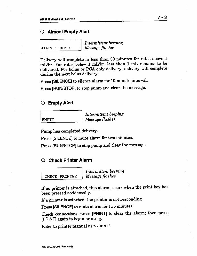
[PRINTJ to clear the alarm; then press[PRINT] again to begin printing.
Refer to printer manual as required.
mL remains to bedelivered. For bolus or PCA only delivery, delivery will completeduring the next bolus delivery.
Press [SILENCE] to silence alarm for lo-minute interval.
Press [RUN/STOP] to stop pump and clear the message.
0 Empty Alert
Pump has completed delivery.
Press [SILENCE] to mute alarm for two minutes.
Press [RUN/STOP] to stop pump and clear the message.
0 Check Printer Alarm
CHECK PRINTERIntermittent beepingMessage flashes
If no printer is attached, this alarm occurs when the print key hasbeen pressed accidentally.
If a printer is attached, the printer is not responding.
Press [SILENCE] to mute alarm for two minutes.
Check connections, press
mL/hr, less than 1 mL/hr. For rates below 1
& Alarms 7-3
0 Almost Empty Alert
ALMOST EMPTYIntermittent beepingMessage flashes
Delivery will complete in less than 30 minutes for rates above 1
APM II Alerts
6195)430-6OOQ32-001 (Rev.
1
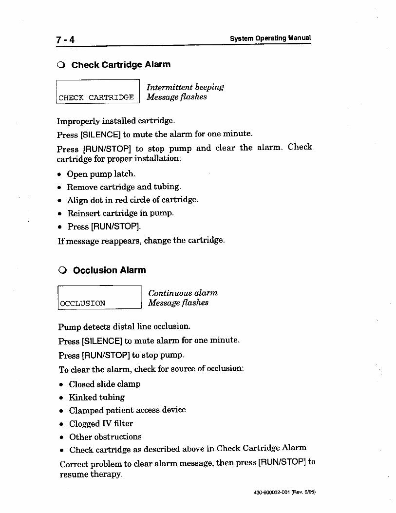
Intermittent beepingMessage flashes
Improperly installed cartridge.Press [SILENCE] to mute the alarm for one minute.
Press [RUN/STOP] to stop pump and clear the alarm. Checkcartridge for proper installation:
l Open pump latch.l Remove cartridge and tubing.l Align dot in red circle of cartridge.l Reinsert cartridge in pump.l Press [RUN/STOP].
If message reappears, change the cartridge.
0 Occlusion Alarm
Pump detects distal line occlusion.
Press [SILENCE] to mute alarm for one minute.
Press [RUN/STOP] to stop pump.
To clear the alarm, check for source of occlusion:
Closed slide clampKinked tubingClamped patient access deviceClogged IV filterOther obstructionsCheck cartridge as described above in Check Cartridge Alarm
Correct problem to clear alarm message, then press [RUN/STOP] toresume therapy.
7-4 System Operating Manual
0 Check Cartridge Alarm
CHECK CARTRIDGE
6/95)43MQOO32-001 (Rev.
/
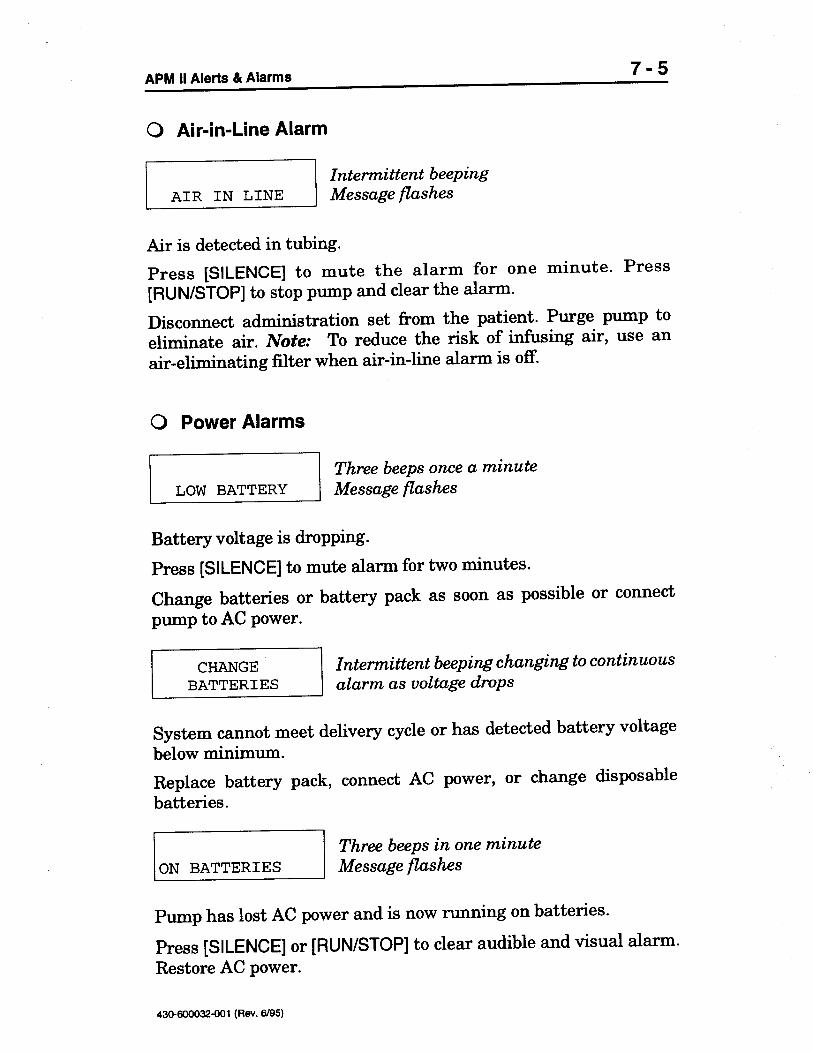
Three beeps in one minuteMessage flashes
Pump has lost AC power and is now running on batteries.
Press [SILENCE] or [RUN/STOP] to clear audible and visual alarm.Restore AC power.
/Intermittent beeping changing to continuousalarm as voltage drops
System cannot meet delivery cycle or has detected battery voltagebelow minimum.
Replace battery pack, connect AC power, or change disposablebatteries.
[ON BATTERIES
B:E::ES /
flashes
Battery voltage is dropping.
Press [SILENCE] to mute alarm for two minutes.
Change batteries or battery pack as soon as possible or connectpump to AC power.
Message / I LOW BATTERYThree beeps once a minute
& Alarms 7-5
0 Air-in-Line Alarm
Air is detected in tubing.
Press [SILENCE] to mute the alarm for one minute. Press[RUN/STOP] to stop pump and clear the alarm.
Disconnect administration set from the patient. Purge pump toeliminate air. Note: To reduce the risk of infusing air, use anair-eliminating filter when air-in-line alarm is off.
0 Power Alarms
APM II Alerts

6195)
riContinuous alarm
[PURGE] has been pressed for more than four minutes.
Press [ENTER] + [A] + [A] to silence the alarm and clear the message.
0 Malfunction Alarm
The system detects a mechanical or computer problem.
The alarm cannot be muted.
Note: Codes 1, 8, 9, 10, and 15 cannot bethese codes appear, call Abbott Clinicall-800-338-7867.
cleared by the user. IfCustomer Support at
All other internal malfunction codes can usually be cleared by theuser. To clear an internal malfunction code, complete the followingsteps:
Press [ON/OFF] to turn the pump off.Disconnect AC power and/or remove batteries.For code 19 only: Verify that an Abbott approved power supplyis in use. Allow one minute to elapse before reconnecting powersupply to allow the fuse to reset.Reconnect power source(s).Press [ON/OFF] to turn the pump on.
If pump completes its self-test, the malfunction alarm is cleared.Verify program. Press [RUN/STOP] to resume therapy.
If problem persists, remove pump from service, recordmalfunction code number and software version, and callAbbott Clinical Customer Support at l-800-338-7867.
430-600032-001 (Rev.
7-6 System Operating Manual
0 Purge Overuse Alarm

6/95)43tMQOO32-001 (Rev.
- history.
12 Motor runaway. Motor appears to be turning during infusion whenit should be off.
13 Voltage present on motor when it should be off. Motor appears tobe on when it should be off.
14 Ext. NVRAM does not acknowledge message.
15 Error writing to internal NVRAM.
16 Clock chip error.
17 Clock chip error.
18 SLIM interface voltage level error.
19 Power supply voltage is too high.
& Alarms 7-7
Code Possible Cause of Malfunction Alarm
1 Read Only Memory (ROM) or circular redundancy check (CRC)error. The program or the instructions are not functioning properly.
2 Random Access Memory (RAM) test error. The memory storagearea is not functioning properly.
3 Stack overflow. The program is not executing properly.
4 Keypad active (key held down or pressed) when batteries wereinstalled.
5 Motor runaway before power up test. Motor appears to be turningduring power on when it should be off.
6 ROM check did not complete.
7 RAM check did not complete.
8 Non Volatile Random Access Memory (NVRAM) CRC error inprogram.
9 NVRAM CRC error in run time parameters.
10 NVRAM CRC error.
11 NVRAM CRC error
APM II Alerts

6195)430-600032-001 (Rev.
[5]. If the codehas cleared, the first number that appears after ERR- will be zero.The succeeding numbers indicate up to three prior system errorcodes. Verify program. Press [RUN/STOP] to resume therapy.
If problem persists, remove pump from service, record systemalarm number and software version, and call Abbott ClinicalCustomer Support at l-800-338-7867.
Code Possible Cause of System Alarm
1 Motor speed incorrect. Motor not running at expected speed.
2 Motor is not turning when it should.
3 At high rates, the motor is not off when it should be.
4 At low rates, the motor is not off when it should be.
5 Excessive motor current while running.
6 While purging, the motor is not turning when it should be.
7 Excessive motor current while purging.
8 The pump is not running at the expected speed.
9 The pump may not be running at the expected speed or motorcalculations were not done (may occur with occlusions).
10 Overuse of purge.
7-8
0 System Alarm
System Operating Manual
The system detects a problem with the motor circuit or the cartridge.
Press [SILENCE] to mute alarm for one minute. Press [RUN/STOP]to stop pump and clear the message.
Check cartridge for problem. For error code 5 or 7, replace thecartridge if it is difficult to rotate.
Verify that the system error codes have been cleared by pressingand releasing [ENTER], then pressing and holding
6/05)43MOOO32-001 (Rev.
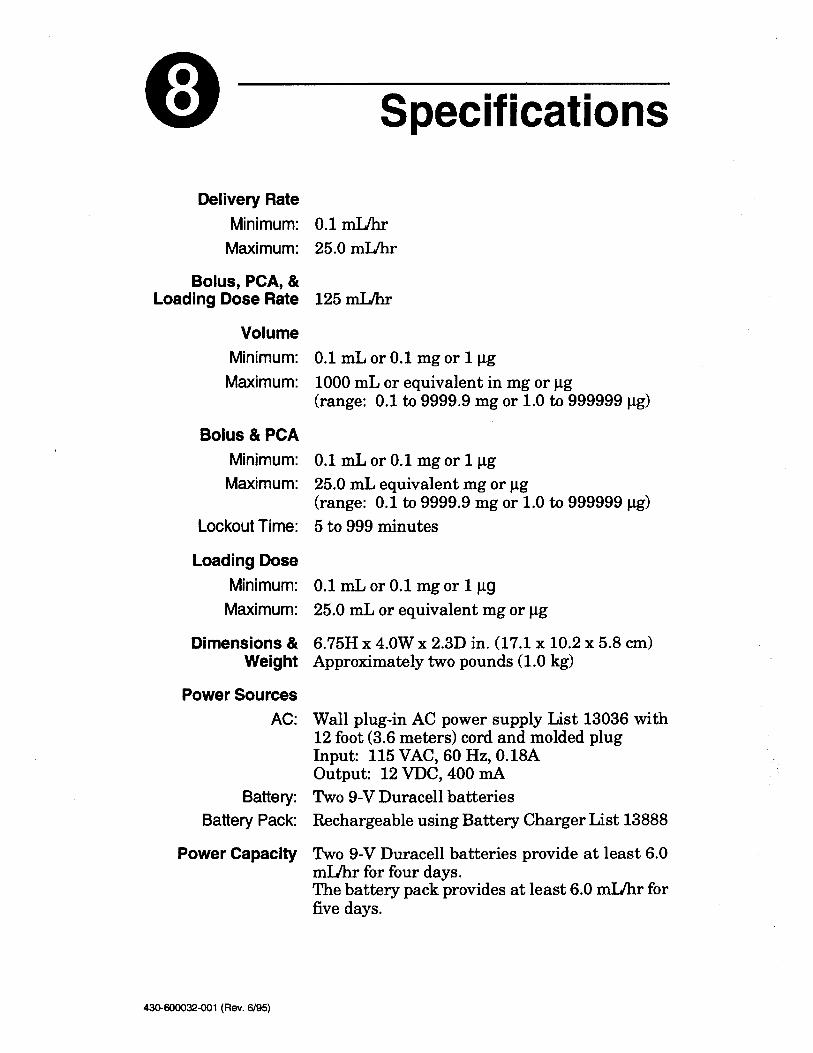
mUhr forfive days.The battery pack provides at least 6.0 mUhr for four days.
mATwo 9-V Duracell batteriesRechargeable using Battery Charger List 13888
Two 9-V Duracell batteries provide at least 6.0
VDC, 400 0.18A
output: 12
2.3D in. (17.1 x 10.2 x 5.8 cm)Approximately two pounds (1.0 kg)
Wall plug-in AC power supply List 13036 with12 foot (3.6 meters) cord and molded plugInput: 115 VAC, 60 Hz,
4.OW x 6.75H x
pgmL or equivalent mg or pg
25.0 mL or 0.1 mg or 1
clg>5 to 999 minutes
0.1
to 999999pg
(range: 0.1 to 9999.9 mg or 1.0mL equivalent mg or
kg25.0
mL or 0.1 or 1mg
cLg>
0.1
i.l.g(range: 0.1 to 9999.9 mg or 1.0 to 999999
mL or equivalent in mg or pg
1000 mL or 0.1 1mgor
mI.Jbr
0.1
InLIhr
125
InLlhr25.0
&Weight
Power SourcesAC:
Battery:Battery Pack:
Power Capacity
0.1
& PCAMinimum:
Maximum:
Lockout Time:
Loading DoseMinimum:
Maximum:
Dimensions
&Loading Dose Rate
VolumeMinimum:
Maximum:
Bolus
0 Specifications
Delivery RateMinimum:
Maximum:
Bolus, PCA,
00

6B5)
EMPTYAIR IN LINE4 HOUR LIMIT
MALFUNCTION
430-600032-001 (Rev.
TOO SMALLCHECK CARTRIDGEALMOST EMPTYPURGE OVERUSE1 HOUR LIMIT
SYSTEM ALARM
CHECK PRINTER
LOW BATTERYSTARTAMOUNT TOO LARGEOCCLUSION
150+ or 180si Printers
The following are screen displays for alarm andalert conditions. Go to Section 7, Alerts andAlarms, for a description of each condition.ON BATTERIESCHANGE BATTERIESAMOUNT
RS232C serial interface port; isolated interfacecircuit for use with Seiko DPU411, or KodakDiconix
&3minutes per month or better.
pL of air.Air alarm off.
A time of day clock allows logging of historyevent time and date. Accuracy of the clock is
fi of air.Pump alarms at approx. 300
+60” C; 10 to 90% relative humidity
Microprocessor controlled eccentric-rotorperistaltic motor
At least one year when power is removed fromthe pump.
The keypad consists of 20 soft keys. The bolusjack is located on the side of the pump. The ACpower port is located on the bottom of the pump.
Liquid crystal display (LCD) with backlight.
Pump alarms at approx. 100
-20” to
+40” C; 10 to 90% relative humidity+lO” to &
Storage:
Pump Mechanism
Memory Protection
Operating Controls
Display
Air SensitivityHIGH:
LOW:
OFF:
Real Time Clock
Printer Port andInterface
Alerts and Alarms
8-2 System Operating Manual
EnvironmentalConditionsOperating:
Transportation