ABB PTMV Poland 2003 ABB PTMV Division Factory in Przasnysz MV Switch Disconnectors NAL/F and AM.
67
ABB PTMV Poland 2003 ABB PTMV Division Factory in Przasnysz MV Switch Disconnectors NAL/F and AM
-
Upload
gerard-small -
Category
Documents
-
view
242 -
download
4
Transcript of ABB PTMV Poland 2003 ABB PTMV Division Factory in Przasnysz MV Switch Disconnectors NAL/F and AM.

AB
B P
TM
V P
olan
d20
03
ABB PTMV DivisionFactory in Przasnysz
MV Switch Disconnectors
NAL/F and AM

AB
B P
TM
V P
olan
d
BU 3420 - MV fuses / MV Switch Disconnectors
BWMW
CEF
SWITCH DISCONNECTORS
Indoor
NAL/F AM
Rotary type:
AIRSWITCH series

AB
B P
TM
V P
olan
d
Based on modular principle Simply and reliable design, A lot of additional equipment, Wide range of application with easy installation and maintenance.
BU 3420 - Switch Disconnector type NAL/F
Type NAL / F - INDOOR
Rated voltage [kV] 17.5Pole distance [mm] 150 210 170 170 235 270Rated current [A] 630 800Mechanisms
400 - 630 - 1250K KS A
2412 36360

AB
B P
TM
V P
olan
d
12, 17,5 i 24 kV / 400, 630 i 1250 A 36 kV / 630 i 800 A
BU 3420 - Switch Disconnector type NAL/F

AB
B P
TM
V P
olan
d
• 3-pole switch disconnector and switch fuse combination
• IEC 265-1 (actual: IEC 60 265-1) - 100 close / open operations at 630 A
• Class E1 24kV
• Class E3 12/17,5/36 kV
• IEC 420 (actual: IEC 62271-105) Alternating current switch-fuse combinations
• More than 500 000 units in service world wide
• Production capacity of 25 000 units per annum
BU 3420 - Switch Disconnector type NAL/F

AB
B P
TM
V P
olan
d
BU 3420 - Switch Disconnector type NAL/F

AB
B P
TM
V P
olan
d
BU 3420 - NAL Switches – main types of switches main types of switches

AB
B P
TM
V P
olan
d
BU 3420 - NAL Switches – main types of switchesmain types of switches

AB
B P
TM
V P
olan
d
BU 3420 - Switch Disconnector type NAL/F
Auxiliary switch2;4;8NO+NC
Motor operation on switch mounted
Shaft extension for Left-Hand side operation
Mechanical interlocking
Earthing switch type E
Operating mechanism
Hand operating type HE(upper part) - bevel gearOperating handle
Auxiliary switch for installationOf fuse interruption
Shunt trip coil for A-mechanism
Hand operating type HE(lower part)-Front bearing
Motor operation mountedin front

AB
B P
TM
V P
olan
d Quick make earthing switch type E
BU 3420 - Switch Disconnector type NAL/F
Earthing switch type EB For separate installation
AB
B P
TM
V P
olan
d
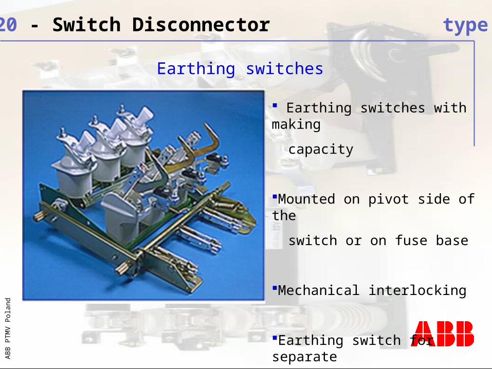
Earthing switches with making
capacity
Mounted on pivot side of the
switch or on fuse base
Mechanical interlocking
Earthing switch for separate
installation
BU 3420 - Switch Disconnector type NAL/F
Earthing switches

AB
B P
TM
V P
olan
d
Type UEMC 40 K3 /NM mounted on the mechanism
Type UEMC 40 A2 mounted on the front panel
BU 3420 - Switch Disconnector type NAL/F
UEMC 40 K3
NM 24…220

AB
B P
TM
V P
olan
d
1. Latched snap action - type KS
2. Stored spring energy – type A
With two springs
3. Snap action -type K
With one spring
3
1
2
BU 3420 - Switch Disconnector type NAL/F

AB
B P
TM
V P
olan
d
• Bevel gear
• Connection rod
• Front bearing with cardanic joint- optional blocking coil
• Operating handle
• Shaft extension
- Left – hand side operation
- Mechanical interlocking
BU 3420 - Switch Disconnector type NAL/F
Hand operating mechanism type HE:

AB
B P
TM
V P
olan
d
Mounting example for hand operating mechanism
90 - Transmission with HE
BU 3420 - Switch Disconnector type NAL/F

AB
B P
TM
V P
olan
d
• Cable sectionalizer and transformer switch
• Motor switch (with motor fuse CMF)
• Switching of capacitor banks
• Component for local manufactured panels
• Used in switch cubicles
• Compact substation (kiosk)
• Utility and industrial application
BU 3420 - Switch Disconnector type NAL/F
Applications

AB
B P
TM
V P
olan
d
BU 3420 - Switch Disconnector type NAL/F
Application example

AB
B P
TM
V P
olan
d
NAL in UniSafe and UniGear cubicleNAL in substation
BU 3420 - Switch Disconnector type NAL/F
Applications

AB
B P
TM
V P
olan
d
BU 3420 - Switch Disconnector type NAL/F
Open switch

AB
B P
TM
V P
olan
d
BU 3420 - Switch Disconnector type NAL/F
Connecting of the switch
• Connecting main knife

AB
B P
TM
V P
olan
d
BU 3420 - Switch Disconnector type NAL/F
Connected switch

AB
B P
TM
V P
olan
d
BU 3420 - Switch Disconnector type NAL/F
Switching off
• flame arc breaking

AB
B P
TM
V P
olan
d
BU 3420 - Switch Disconnector type NAL/F

AB
B P
TM
V P
olan
d
BU 3420 - Switch Disconnector type NAL/F

AB
B P
TM
V P
olan
d
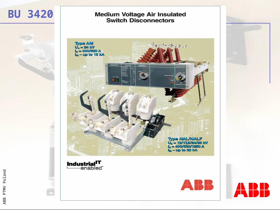
BU 3420 – AirSwitch series
The switchboard ROTARY switches and isolators
AM AR/AS
Available in two versions:
AM type switch disconnector (24kV; 400/630A)
AR/AS type rotary isolators (24kV; 400/630/ 800/1250A)

AB
B P
TM
V P
olan
d
Air-insulated
Rotary type
630 A breaking capacity
40 kA making capacity
2 positions: LINE – OPEN
Provide segregation between busbar and feeder compartments
Interlocked with a separate eathing switch
Switch Disconnector AM
BU 3420 - Switch Disconnector type AM

AB
B P
TM
V P
olan
d
Switch Disconnector AM
BU 3420 - Switch Disconnector type AM
Voltage signalling device
Key lock
Door lock
Auxliary contacts
Shunt opening release

AB
B P
TM
V P
olan
d
Air-insulated
Rotary type
400, 630, 800, 1250 A rated current
up to 25 kA short time withstand current
Switch Isolator AS/AR
BU 3420 - Isolators type AR/AS
AB
B P
TM
V P
olan
d
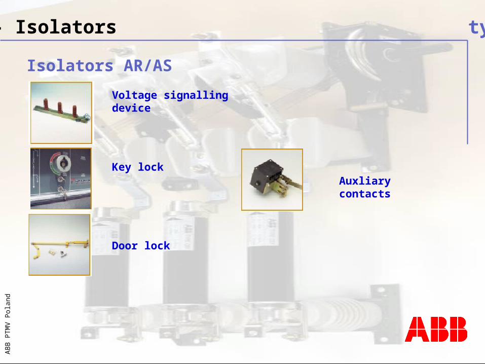
Isolators AR/AS
BU 3420 - Isolators type AR/AS
Voltage signalling device
Key lock
Door lock
Auxliary contacts

AB
B P
TM
V P
olan
d
Switch disconnector applications
BU 3420 - Switch Disconnector type AM

AB
B P
TM
V P
olan
d
Switch disconnector with fuses
Caption:1 Busbars
2 Switch Disconnector
3 Fuses
4 Earthing switch
5 Cable fixing point
1
2
3
45
BU 3420 - Switch Disconnector type AM

AB
B P
TM
V P
olan
d
Isolators applications
BU 3420 – Isolators type AR/AS
AB
B P
TM
V P
olan
d
BU 3420

AB
B P
TM
V P
olan
d
BU 3420 – Switches
EUROPE: WE+CEEAUSTRIA BELGIUM BELARUSBULGARIACROATIACZECH REP.DENMARKESTONIAFINLANDGERMANYGREAT BRITAINGREECEHUNGARYICELANDIRELANDITALYLATVIALITHUANIALUXEMBOURGNORWAYPOLANDPORTUGALROMANIASLOVAKIASPAINSWEDENSWITZERLAND
ASIA: AUSTRALIACHINAHONG KONGINDIAINDONESIAJAPANKOREA NEW ZEALANDMALAYSIA PAKISTANPHILIPPINESSINGAPORETAIWANTHAILANDVIETNAM
MIDDLE EAST:ARAB EMIRATESEGYPTIRANISRAELJORDANLEBANONOMANQATARSAUDI ARABIASYRIATUNISIATURKEYSOUTH&NORTH AMERICA:
ARGENTINABOLIVIABRAZILCANADACHILECOLOMBIAECUADORMEXICOPARAGUAYPERUUSAVENEZUELA
AFRICA: SENEGALSOUTH AFRICATANZANIA

AB
B P
TM
V P
olan
d
• Modern machinery
• ISO 9001/14001 certified
• IEC; ANSI, CSA, GOST Standards
BU 3420 - Switch Disconnector type NAL/F

AB
B P
TM
V P
olan
d
BU 3420

AB
B P
TM
V P
olan
d
BU 3420 – switch disconnectors – normal operating conditionsnormal operating conditions
•Maximum ambient temperature +40C•Minimum ambient temperature is -25C•The altitude does not exceed 1000m (3300ft)•The ambient air is not excessively polluted by dust, smoke, corrosive or flammable gases, vapour or salt •Typical conditions of humidity for indoor installations are fulfilled

AB
B P
TM
V P
olan
d
BU 3420 - switch disconnectors – Standards
•IEC 60265 Switches for voltage above 1 kV and less than 52 kV•IEC 60694 Common specification for high-voltage switchgearand controlgear standards•IEC 60129 Alternating current disconnectors and earthing switches•IEC 62271-105 High voltage switchgear and controlgear
•Part 105-Alternating current switch-fuse combinations •former name IEC 420

AB
B P
TM
V P
olan
d
BU 3420 - switch disconnectors – application application
Altitude correction factors for Test and Rating Voltages
Altitude correction factors for Rated Current and Temperature Rise

AB
B P
TM
V P
olan
d
BU 3420 - switch disconnectors – Switch-fuse Switch-fuse rratingsatings
Switch nameplate

AB
B P
TM
V P
olan
d
BU 3420 - switch disconnectors – breaking capacitybreaking capacity

AB
B P
TM
V P
olan
d
BU 3420 - switch disconnectors – breaking capacitybreaking capacity

AB
B P
TM
V P
olan
d
BU 3420 - switch disconnectors – breaking capacitybreaking capacity

AB
B P
TM
V P
olan
d
BU 3420 - switch disconnectors – breaking capacitybreaking capacity

AB
B P
TM
V P
olan
d
BU 3420 - switch disconnectors – breaking capacitybreaking capacity

AB
B P
TM
V P
olan
d
BU 3420 - switch disconnectors – breaking capacitybreaking capacity

AB
B P
TM
V P
olan
d
BU 3420 - HV fuses – Coordination with load break switchCoordination with load break switch
Minimum breaking current with switch disconnector coordination

AB
B P
TM
V P
olan
d
BU 3420 - switch disconnectors – Operating methodsOperating methods
When using NALF - A or KS operating mechanism are suitable only

AB
B P
TM
V P
olan
d
BU 3420 - switch disconnectors – Operating methodsOperating methods

AB
B P
TM
V P
olan
d
BU 3420 - switch disconnectors – Coordination with switchCoordination with switch
Transfer current (striker operation) value of the three-phase symmetrical current at which the fuses and the switch exchange breaking duties NOTE Above this value the three-phase current is interrupted by the fuse only. Immediately below this value, the current in the first-pole-to-clear is interrupted by the fuse and the current in the other two poles by the switch, or by the fuses, depending on the tolerances of the fuse time current characteristic and the fuse-initiated opening time of the switch.

AB
B P
TM
V P
olan
d
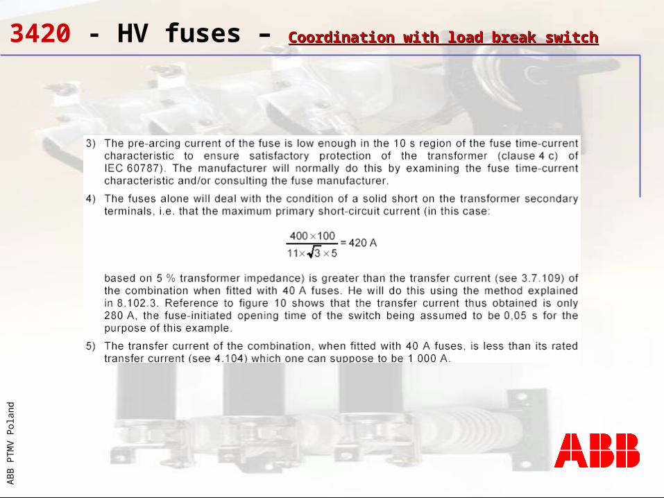
BU 3420 - HV fuses – Coordination with load break switchCoordination with load break switch

AB
B P
TM
V P
olan
d
BU 3420 - HV fuses – Coordination with load break switchCoordination with load break switch
The fuses are incorporated in order to extend the short-circuit breaking rating of the combination beyond that of the switch alone. They are fitted with strikers in order both to open automatically all three poles of the switch on the operation of a fuse and to achieve a correct operation at values of fault current above the minimum melting current but below the minimum breaking current of the fuses The minimum breaking current is normally in the range from 2 to 7 times fuse rated current (dependent of fuse rated current). Naturally the question is what will happen if we get a fault current in the range from minimum melting to minimum breaking current? If this happen, when the last conductor melts off, an arc starts and we get an arc voltage between the fuse terminals as described earlier. The fuse will withstand the arc and the energy dissipated for 200 to 400 ms. Due to the arc voltage the striker system will operate and combined with a load break switch, tripping on signal from the striker, the load break switch will open and interrupt the current before the fuse is damaged.

AB
B P
TM
V P
olan
d
BU 3420 - HV fuses – Coordination with load break switchCoordination with load break switch
That means in the range from minimum melting current to minimum breaking current the fuse gives the signal and the breaker clears the fault. In this way by combining a load break switch with a pre charged operated mechanism which can be tripped by the fuse striker system, we can obtain protection from minimum melting current and up to the max breaking current for the fuse. When we reach a certain fault current level the fuse will break and clear the fault before the breaker is able to open due to the mechanical operating time of the switch (this is normally 40 -70 ms dependent of type) and we do not get any problem with the breaking capacity of the load break switch, the fuse has already cleared the fault when the breaker opens. We will have a certain range where fuse and switch have approximately same clearing time. This happen at the take over current as shown on earlier slide. The switch itself must have a max. breaking capacity which overlaps the take over point. The requirement to a fuse switch combination is given in IEC 62271-105 (former IEC 420). and will determine what max. rated current the fuse can have to be sure you have the necessary safety margin for coordination between fuse and switch.

AB
B P
TM
V P
olan
d
BU 3420 - switch disconnectors – general rulesgeneral rules
Low over-currents

AB
B P
TM
V P
olan
d
BU 3420 - switch disconnectors – general rulesgeneral rules
Minimum breaking current

AB
B P
TM
V P
olan
d
BU 3420 - HV fuses – general rulesgeneral rules

AB
B P
TM
V P
olan
d
BU 3420 - HV fuses – Coordination with load break switchCoordination with load break switch

AB
B P
TM
V P
olan
d
BU 3420 - HV fuses – Coordination with load break switchCoordination with load break switch

AB
B P
TM
V P
olan
d
BU 3420 - HV fuses – Coordination with load break switchCoordination with load break switch
AB
B P
TM
V P
olan
d
BU 3420 - HV fuses – Coordination with load break switchCoordination with load break switch

AB
B P
TM
V P
olan
d
BU 3420 - HV fuses – Coordination with load break switchCoordination with load break switch

AB
B P
TM
V P
olan
d
BU 3420 - NAL Switches – Tightening forcesTightening forces

AB
B P
TM
V P
olan
d
BU 3420 - NAL Switches – Assembling mistakesAssembling mistakes

AB
B P
TM
V P
olan
d
BU 3420 - NAL Switches – Assembling mistakesAssembling mistakes

AB
B P
TM
V P
olan
d
BU 3420 - NAL Switches – Assembling mistakesAssembling mistakes

AB
B P
TM
V P
olan
d
BU 3420 - NAL Switches – Your questions? Your questions?
AB
B P
TM
V P
olan
d©
BA
PT
MV
– P
age4
1