ABB Drives User’s Manual - Ortman Electronics · If you have any questions concerning your ABB...
30
ABB Drives Pulse Encoder Interface Module RTAC-01 User’s Manual
Transcript of ABB Drives User’s Manual - Ortman Electronics · If you have any questions concerning your ABB...

ABB Drives
Pulse Encoder Interface ModuleRTAC-01
User’s Manual


©
Pulse Encoder Interface ModuleRTAC-01
User’s Manual
3AFE 64486853 REV A EN
EFFECTIVE: 1.5.2002
2002 ABB Oy. All Rights Reserved.


Safety instructions
Overview This chapter states the general safety instructions that must be followed when installing and operating the RAIO-01 Analogue I/O Extension module.
The material in this chapter must be studied before attempting any work on, or with, the unit.
In addition to the safety instructions given below, read the complete safety instructions of the specific drive you are working on.
General safety instructions
WARNING! All electrical installation and maintenance work on the drive should be carried out by qualified electricians only.
The drive and adjoining equipment must be properly earthed.
Do not attempt any work on a powered drive. After switching off the mains, always allow the intermediate circuit capacitors 5 minutes to discharge before working on the frequency converter, the motor or the motor cable. It is good practice to check (with a voltage indicating instrument) that the drive is in fact discharged before beginning work.
The motor cable terminals of the drive are at a dangerously high voltage when mains power is applied, regardless of motor operation.
There can be dangerous voltages inside the drive from external control circuits even when the drive mains power is shut off. Exercise appropriate care when working on the unit. Neglecting these instructions can cause physical injury or death.
RTAC-01 User’s manual iii

Safety instructions
iv RTAC-01 User’s manual

Table of contents
Safety instructions
Overview . . . . . . . . . . . . . . . . . . . . . . . . . . . . . . . . . . . . . . . . . . . . . . . . . . . . . iiiGeneral safety instructions. . . . . . . . . . . . . . . . . . . . . . . . . . . . . . . . . . . . . . . . iii
Table of contents
Chapter 1 – Introduction
Intended audience . . . . . . . . . . . . . . . . . . . . . . . . . . . . . . . . . . . . . . . . . . . . 1-1Before you start . . . . . . . . . . . . . . . . . . . . . . . . . . . . . . . . . . . . . . . . . . . . . . 1-1What this manual contains . . . . . . . . . . . . . . . . . . . . . . . . . . . . . . . . . . . . . . 1-2
Chapter 2 – Overview
Overview . . . . . . . . . . . . . . . . . . . . . . . . . . . . . . . . . . . . . . . . . . . . . . . . . . . 2-1The RTAC-01 module . . . . . . . . . . . . . . . . . . . . . . . . . . . . . . . . . . . . . . . . . 2-1
Module layout . . . . . . . . . . . . . . . . . . . . . . . . . . . . . . . . . . . . . . . . . . . . . . 2-1Delivery check . . . . . . . . . . . . . . . . . . . . . . . . . . . . . . . . . . . . . . . . . . . . . 2-2Compatibility . . . . . . . . . . . . . . . . . . . . . . . . . . . . . . . . . . . . . . . . . . . . . . . 2-2Warranty and liability information . . . . . . . . . . . . . . . . . . . . . . . . . . . . . . . 2-2
Chapter 3 – Installation
Mounting . . . . . . . . . . . . . . . . . . . . . . . . . . . . . . . . . . . . . . . . . . . . . . . . . . . 3-1Terminal designations . . . . . . . . . . . . . . . . . . . . . . . . . . . . . . . . . . . . . . . . . 3-2Power consumption . . . . . . . . . . . . . . . . . . . . . . . . . . . . . . . . . . . . . . . . . . . 3-3Encoder wiring . . . . . . . . . . . . . . . . . . . . . . . . . . . . . . . . . . . . . . . . . . . . . . . 3-5
Phasing. . . . . . . . . . . . . . . . . . . . . . . . . . . . . . . . . . . . . . . . . . . . . . . . . . . 3-6Encoder output types . . . . . . . . . . . . . . . . . . . . . . . . . . . . . . . . . . . . . . . . 3-7Wiring diagrams . . . . . . . . . . . . . . . . . . . . . . . . . . . . . . . . . . . . . . . . . . . . 3-8
Node address selection . . . . . . . . . . . . . . . . . . . . . . . . . . . . . . . . . . . . . . . 3-12Programming . . . . . . . . . . . . . . . . . . . . . . . . . . . . . . . . . . . . . . . . . . . . . . . 3-12
RTAC-01 User’s manual v

Table of contents
Chapter 4 – Fault tracing
Diagnostic LEDs . . . . . . . . . . . . . . . . . . . . . . . . . . . . . . . . . . . . . . . . . . . . . . 4-1Option slot installation . . . . . . . . . . . . . . . . . . . . . . . . . . . . . . . . . . . . . . 4-1I/O Module Adapter installation . . . . . . . . . . . . . . . . . . . . . . . . . . . . . . . 4-1
Appendix A – Technical data
vi RTAC-01 User’s manual

Chapter 1 – Introduction
Intended audience
The manual is intended for the people who are responsible for commissioning and using an RTAC-01 Pulse Encoder Interface module with the ACS 800 drive. The reader is expected to have a basic knowledge of electrical fundamentals, electrical wiring practices and how to operate the drive.
Before you start It is assumed that the drive is installed and ready to operate before starting the installation of the extension module.
In addition to conventional installation tools, have the drive manuals available during the installation as they contain important information not included in this manual. The drive manuals are referred to at various points of this document.
RTAC-01 User’s manual 1-1

Chapter 1 – Introduction
What this manual contains
This manual contains information on the wiring, configuration and use of the RTAC-01 module.
Safety instructions are featured in the first few pages of this manual.
Chapter 2 – Overview contains a short description of the RTAC-01 Pulse Encoder Interface module, a delivery checklist and warranty information.
Chapter 3 – Installation contains instructions for module hardware settings, mounting and cabling.
Chapter 4 – Fault tracing explains fault tracing and the LED indications of the RTAC-01 module.
Appendix A contains technical data.
1-2 RTAC-01 User’s manual

Chapter 2 – Overview
Overview This chapter contains a short description of the Pulse Encoder Interface module, a delivery checklist, and warranty information.
The RTAC-01 module
The RTAC-01 Pulse Encoder Interface module offers an interface for a digital pulse encoder connection. A pulse encoder should be used if accurate speed or position (angle) feedback from the motor shaft is required.
Module layout
654321 65432187
Fixing screw (GND)
Node ID selector (S1)
Diagnostic LEDs
Fixing screw(CHASSIS)
0 8
4
C
2 6
AE
13 5
79
BD
F
Terminal block forencoder signals (X2)
Terminal block for encoderpower connections (X1)
CHAS
SIS
GND
NODE
ID
SHLD
RTAC
-01
PULS
E EN
CODE
R IN
TERF
ACE
X2 X1
WD/
INIT
CHB
CHA
SHLD
CHA+
CHA-
CHB+
CHB-
CHZ+
CHZ-
0 V
0 V
V OU
T
+15V
V IN
+24V
RTAC-01 User’s manual 2-1

Chapter 2 – Overview
Delivery check The option package contains:
• RTAC-01 module
• Encoder supply voltage selection jumper
• Two screws (M3×8 mm)
• This manual.
Compatibility The RTAC-01 is compatible with ACS 800 Standard Application Program version ASXR7000 or later.
Warranty andliability
information
The warranty for your ABB drive and options covers manufacturing defects. The manufacturer carries no responsibility for damage due to transport or unpacking.
In no event and under no circumstances shall the manufacturer be liable for damages and failures due to misuse, abuse, improper installation, or abnormal conditions of temperature, dust, or corrosives, or failures due to operation above rated capacities. Nor shall the manufacturer ever be liable for consequential and incidental damages.
The period of manufacturer's warranty is 12 months, and not more than 18 months, from the date of delivery. Extended warranty may be available with certified start-up. Contact your local distributor for details.
Your local ABB Drives company or distributor may have a different warranty period, which is specified in their sales terms, conditions, and warranty terms.
If you have any questions concerning your ABB drive, contact your local distributor or ABB Drives office.
The technical data and specifications are valid at the time of printing. ABB reserves the right to subsequent alterations.
2-2 RTAC-01 User’s manual

Chapter 3 – Installation
WARNING! Follow the safety instructions given in this guide and in the ACS 800 Hardware Manual.
Mounting The RTAC-01 is to be inserted into the position marked SLOT 1 or SLOT 2 on the drive. The module is held in place with plastic retaining clips and two screws. The screws also provide the earthing of the I/O cable shield connected to the module, and interconnect the GND signals of the module and the RMIO board.
On installation of the module, the signal and power connection to the drive is automatically made through a 38-pin connector.
The module can alternatively be mounted on a DIN rail-mountable AIMA-01 I/O Module Adapter (not available at the time of publication).
Mounting procedure:
1. Insert the module carefully into SLOT 1 or SLOT 2 on the RMIO board until the retaining clips lock the module into position.
2. Fasten the two screws (included) to the stand-offs.
Note: Correct installation of the screws is essential for fulfilling the EMC requirements and for proper operation of the module.
RTAC-01 User’s manual 3-1

Chapter 3 – Installation
Terminal designations
X1 Marking Description
1 0 V Encoder power supply, either 15 or 24 V DC (according to jumper selection on terminals 4, 5 and 6).(0 V is also used with single-ended encoder connection for balancing the A+, B+ and/or Z+ conductors. See Figures 3-3 to 3-6.)
2 0 V
3 V OUT
4 +15V Encoder supply voltage selection:Terminals 4 and 5 connected: 15 V (default)Terminals 5 and 6 connected: 24 V(Jumper is supplied with the RTAC module)Max. 5 watts (see Power consumption below)
5 V IN
6 +24V
Connected internally on the circuit board.
X2 Marking Description
1 SHLDShield
For earthing of the encoder cable shields. Internally connected to the frame.2 SHLD
3 A+ A • Max. signal frequency: 200 kHz• Signal levels:
“1” > 7.6 V, “0” < 5 V (for 15 V supply)“1” > 12.2 V, “0” < 8 V (for 24 V supply)
• Input channels isolated from the logic, power supply, and earth
• When the drive runs in the Forward direction,channel A should lead channel B by 90° (electrical)
• Channel Z: One pulse per revolution (used in positioning applications only)
4 A- A
5 B+ B
6 B- B
7 Z+ Z
8 Z- Z
3-2 RTAC-01 User’s manual

Chapter 3 – Installation
Power consumption
Without an external power supply, the RTAC-01 can supply 5 W (at either 15 V or 24 V DC) to the encoder. For higher power, an external power supply is required.
As the power consumption of the module depends on many factors (e.g. max. speed of the motor, encoder pulse number per revolution, encoder cable length and leakage capacitance), it should be checked on each occasion if an external power supply is needed. See the encoder documentation for details. Figure 3-2 shows the approximate power consumption of an encoder with differential outputs, based on actual measurements.
The external power supply should be connected as shown below.
Note: With an external power supply, the voltage selection jumper should be removed from X1.
Figure 3-1 External power supply connection diagram
X10 V
0 V
V OUT
+15V
V IN
+24V
SHLD
X2
RTAC
VccVcc
0V
0V
1
2
3
4
5
6
2
RTAC-01 User’s manual 3-3

Chapter 3 – Installation
Figure 3-2 Approximate power consumption of an encoder for four different cable lengths. The chart is based on a measurement with a 24 V DC, 1024 ppr pulse encoder with differential outputs coupled to a motor shaft rotating at 1500 rpm.
0 150 300 450 600 750 900 1050 1200 15001350
0 600 1200 1800 2400 3000 3600 4200 4800 60005400
EPN = 2048 ppr:
EPN = 512 ppr:
EPN = 1024 ppr:
EPN = Encoder pulse numberPidle = Encoder power consumption when idle. See encoder documentation.
Motor speed (rpm)
0 300 600 900 1200 1500 1800 2100 2400 30002700
Pidle
Pidle + 0.25 W
Pidle + 0.5 W
Pidle + 0.75 W
Pidle + 1.0 W
Pidle + 1.25 W
Pidle + 1.5 W
Pidle + 1.75 W
Pidle + 2.0 W
Encoder power consumption
Cable length
300 m
150 m
100 m
20 m
3-4 RTAC-01 User’s manual

Chapter 3 – Installation
Encoder wiring The pulse encoder should be connected to the RTAC module with a cable specified below.
Either a single-ended or differential connection can be used, but the manufacturer’s recommendations should be taken into account. Starting on page 3-8, there are wiring diagrams for different encoder output types. Compare encoder documentation and the diagrams below to determine the output type.
Note: The cable shields should be earthed at the RTAC module only if the encoder is not isolated from the motor and earth. However, if the encoder is isolated from the motor and earth, the cable shields are to be connected to the encoder housing also.
Note: Do not route the encoder cables parallel to power (eg. motor) cables.
Cable construction
4 × (2+1) Twisted pair cable with individual and overall shields.
Conductor cross-sectional area
0.5 to 1.0 mm2
Maximum cable length
Dependent on encoder output type as follows:300 m (differential push-pull)200 m (single-ended push-pull)100 m (open collector or emitter)
RTAC-01 User’s manual 3-5

Chapter 3 – Installation
Phasing When the encoder is connected correctly, running the drive in the Forward (positive speed reference) direction should produce a positive encoder speed feedback.
On incremental encoders, the two output channels, usually marked 1 and 2 or A and B, are 90° (electrical) apart from each other. When rotated clockwise, most encoders – but not all – have channel 1 leading channel 2 as illustrated below. Determine the leading channel by referring to the encoder documentation or by measuring with an oscilloscope.
The encoder output channel that leads when the drive runs Forward should be connected to RTAC input A, the output channel that trails to RTAC input B.
The zero reference output channel (usually marked 0, N or Z) needs to be connected in positioning applications only.
A or 1
A or 1
B or 2
B or 2
Z or 0
Z or 0
3-6 RTAC-01 User’s manual

Chapter 3 – Installation
Encoder outputtypes
The diagram presents some typical encoder output types. The following pages include wiring diagrams for each output type.
Push-pullOpen collector
(Sinking)Open emitter
(Sourcing)
VCC = Encoder input power supply voltageRL = Load resistor at encoder output channel
RL2
VCC
RL1
VCC
OUT
RL
VCC
OUT
VCC
RL
VCC
OUT
RTAC-01 User’s manual 3-7
Chapter 3 – Installation
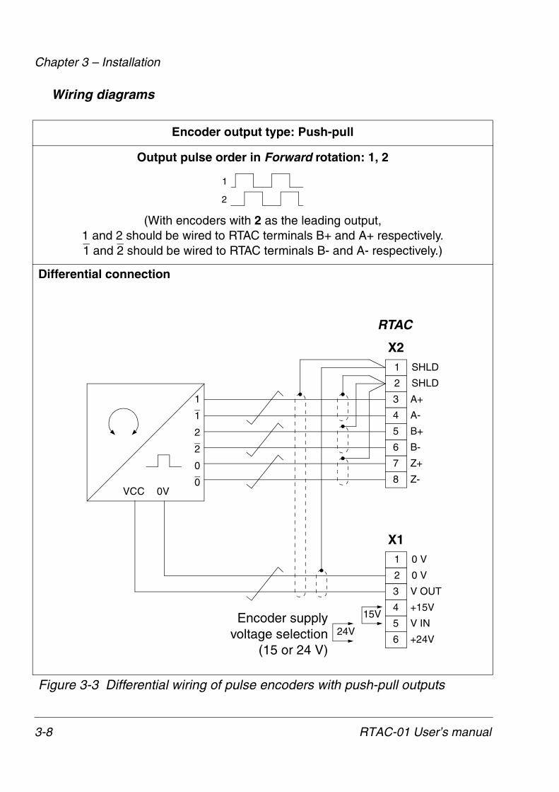
Wiring diagrams
Encoder output type: Push-pull
Output pulse order in Forward rotation: 1, 2
(With encoders with 2 as the leading output,1 and 2 should be wired to RTAC terminals B+ and A+ respectively.1 and 2 should be wired to RTAC terminals B- and A- respectively.)
Differential connection
Figure 3-3 Differential wiring of pulse encoders with push-pull outputs
1
2
1
1
0
0VVCC
2
X1
RTAC
A+
A-
B+
B-
Z+
Z-
2
0
15V
24VEncoder supply
voltage selection(15 or 24 V)
1
2
3
4
5
6
SHLD
SHLD
7
8
V OUT
+15V
V IN
+24V
1
2
3
4
5
6
0 V
0 V
X2
3-8 RTAC-01 User’s manual

Chapter 3 – Installation
Single-ended connection
Figure 3-4 Single-ended wiring of pulse encoders with push-pull outputs
Encoder output type: Push-pull
Output pulse order in Forward rotation: 1, 2
(With encoders with 2 as the leading output,1 and 2 should be wired to RTAC terminals B+ and A+ respectively.1 and 2 should be wired to RTAC terminals B- and A- respectively.)
1
2
1
0
0VVCC
2
X1
RTAC
A+
A-
B+
B-
Z+
Z-
15V
24VEncoder supply
voltage selection(15 or 24 V)
1
2
3
4
5
6
SHLD
SHLD
7
8
V OUT
+15V
V IN
+24V
1
2
3
4
5
6
0 V
0 V
X2
RTAC-01 User’s manual 3-9

Chapter 3 – Installation
Figure 3-5 Wiring of pulse encoders with open collector (sinking) outputs.
Encoder output type: Open collector (Sinking)
Output pulse order in Forward rotation: 1, 2
(With encoders with 2 as the leading output, 1 and 2 should be wired to RTAC terminals B+ and A+ respectively)
1
2
1
0
0VVCC
2
RTAC
A+
A-
B+
B-
Z+
Z-
15V
24VEncoder supply
voltage selection(15 or 24 V)
1
2
3
4
5
6
SHLD
SHLD
7
8
V OUT
+15V
V IN
+24V
1
2
3
4
5
6
0 V
0 V
X2
24V: 1.8…2.2 kΩ15V: 1.0…1.5 kΩ
0.5 W
X1
3-10 RTAC-01 User’s manual

Chapter 3 – Installation
Figure 3-6 Wiring of pulse encoders with open emitter (sourcing) outputs.
Encoder output type: Open emitter (Sourcing)
Output pulse order in Forward rotation: 1, 2
(With encoders with 2 as the leading output, 1 and 2 should be wired to RTAC terminals B+ and A+ respectively)
1
2
1
0
0VVCC
2
RTAC
A+
A-
B+
B-
Z+
Z-
15V
24VEncoder supply
voltage selection(15 or 24 V)
1
2
3
4
5
6
SHLD
SHLD
7
8
V OUT
+15V
V IN
+24V
1
2
3
4
5
6
0 V
0 V
X2
24V: 1.8…2.2 kΩ15V: 1.0…1.5 kΩ
0.5 W
X1
RTAC-01 User’s manual 3-11

Chapter 3 – Installation
Node address selection
If the RTAC-01 module is mounted onto external I/O Module Adapter AIMA-01, choose the proper node ID for the module using the node ID selector (S1).
The settings 0…F correspond to node IDs 16…31. The default setting is 0 (node ID 16).
Setting the node ID is not required when the module is mounted into SLOT 1 or SLOT 2 on the drive.
Programming The RTAC-01 is programmed through drive parameters. These parameters must be checked and adjusted. For further information, see the drive Firmware Manual, Parameter Groups 50 and 98.
3-12 RTAC-01 User’s manual

Chapter 4 – Fault tracing
Diagnostic LEDs There are three diagnostic LEDs on the RTAC-01 module. The CHA (green) and CHB (green) LEDs show the activity on channels A and B. The WD/INIT (yellow) LED shows the status of the module.
WD/INIT is lit when the drive is configuring the module at power-up.
Option slotinstallation
In case the LED does not go out after one second:
• The configuration has failed.
- Cycle the power supply of the drive.
• The module has a hardware failure.
- Ensure the 38-pin connector is properly inserted.
- Contact an ABB service representative.
I/O Module Adapterinstallation
• There is no communication with the drive.
- Check that the drive is powered.
- Check the module node ID.
- Check that the fibre optic cables are connected correctly (transmitters to receivers) and the connectors properly inserted.
- Check the fibre optic cables visually for dirt or flaws.
- Ensure the 38-pin connector is properly inserted.
- Try new fibre optic cables.
- Contact an ABB service representative.
RTAC-01 User’s manual 4-1

Chapter 4 – Fault tracing
4-2 RTAC-01 User’s manual

Appendix A – Technical data
Dimensions:
Mounting: Into an option slot of the RMIO board of the drive or onto external I/O Module Adapter (AIMA-01).
Degree of protection: IP 20
Ambient conditions: The applicable ambient conditions specified for the drive in its Hardware Manual are in effect.
Hardware settings:
• Rotary switch for node ID selection (range 16…31)
Connectors:
• 38-pin parallel bus connector
• Two (one 6-pole, one 8-pole) non-detachable screw-type terminal blocks for max. 2.5 mm2 wire.
95 m
m
34 mm
20 mm 62 mm
65
43
21
65
43
21
8
0
8
4
C
2
6A
E1
35
79
BD
F
CHASSIS
GND
NODE ID
SHLD
RTAC-01PULSE ENCODER INTERFACE
X2
X1
WD/INIT
CHB
CHASHLD
CHA+
CHA-
CHB+
CHB-
CHZ+
CHZ-
0 V
0 V
V OUT
+15V
V IN
+24V
7
RTAC-01 User’s manual A-1

Appendix A – Technical data
Encoder interface:
• CH A, CH B, CH Z, differential or single-ended
• Output voltage 1: +24 V DC ±10%, 5 W max., short-circuit proof
• Output voltage 2: +15 V DC ±10%, 5 W max., short-circuit proof
• Signal levels:"1" >7.6 V, "0" < 5 V (for 15 V supply)"1" >12.2 V, "0" < 8 V (for 24 V supply)
• Frequency: 200 kHz (max.)
• Speed feedback resolution: 0.00305% (15 bits)
• Speed feedback accuracy: 50 ppm
• Maximum encoder cable length: - 300 m (differential push-pull)- 200 m (single-ended push-pull)- 100 m (open collector or emitter)
• Isolated from the logic and earth. Test voltage: 1.5 kV AC, 1 minute
General
• Max. power consumption:140 mA (5 V) + 55 mA (24 V)
• Estimated min. lifetime: 100 000 h
• All materials UL/CSA-approved
• Complies with EMC standards EN 50081-2 and EN 50082-2
A-2 RTAC-01 User’s manual


ABB OyAC DrivesP.O. Box 184FIN-00381 HelsinkiFINLANDTelephone:+358 10 222 000
RTA
C-0
13A
FE
644
8685
3 R
EV
A E
NE
FF
EC
TIV
E: 1
.5.2
002
ABB Inc.Drives & Power Products16250 West Glendale DriveNew Berlin, WI 53151USATelephone:262 785-8378
Fax: +358 10 222 2681Internet: www.abb.com
800 243-4384Fax: 262 780-5135