ABAQUS 6 - 3D PERSPECTIVES | from Dassault...
31
VEHICLE RIDE COMFORT AND DURABILITY SIMULATION USING ABAQUS AND FTIRE USER’S GUIDE ABAQUS 6.14
Transcript of ABAQUS 6 - 3D PERSPECTIVES | from Dassault...

VEHICLE RIDE COMFORT ANDDURABILITY SIMULATION
USING ABAQUS AND FTIREUSER’S GUIDE
ABAQUS 6.14


Abaqus User’s Guide for Vehicle Ride Comfort
and Durability Simulation
Using Abaqus and FTire
Abaqus ID:fti
Printed on: Mon October 20 -- 9:29:02 2014

Legal NoticesCAUTION: This documentation is intended for qualified users who will exercise sound engineering judgment and expertise in the use of the Abaqus
Software. The Abaqus Software is inherently complex, and the examples and procedures in this documentation are not intended to be exhaustive or to apply
to any particular situation. Users are cautioned to satisfy themselves as to the accuracy and results of their analyses.
Dassault Systèmes and its subsidiaries, including Dassault Systèmes Simulia Corp., shall not be responsible for the accuracy or usefulness of any analysis
performed using the Abaqus Software or the procedures, examples, or explanations in this documentation. Dassault Systèmes and its subsidiaries shall not
be responsible for the consequences of any errors or omissions that may appear in this documentation.
The Abaqus Software is available only under license from Dassault Systèmes or its subsidiary and may be used or reproduced only in accordance with the
terms of such license. This documentation is subject to the terms and conditions of either the software license agreement signed by the parties, or, absent
such an agreement, the then current software license agreement to which the documentation relates.
This documentation and the software described in this documentation are subject to change without prior notice.
No part of this documentation may be reproduced or distributed in any form without prior written permission of Dassault Systèmes or its subsidiary.
The Abaqus Software is a product of Dassault Systèmes Simulia Corp., Providence, RI, USA.
© Dassault Systèmes, 2014
Abaqus, the 3DS logo, SIMULIA, and Unified FEA are trademarks or registered trademarks of Dassault Systèmes or its subsidiaries in the US and/or other
countries.
Other company, product, and service names may be trademarks or service marks of their respective owners. For additional information concerning
trademarks, copyrights, and licenses, see the Legal Notices in the Installation and Licensing Guide for the release of Abaqus that you are using.
Abaqus ID:fti
Printed on: Mon October 20 -- 9:29:02 2014
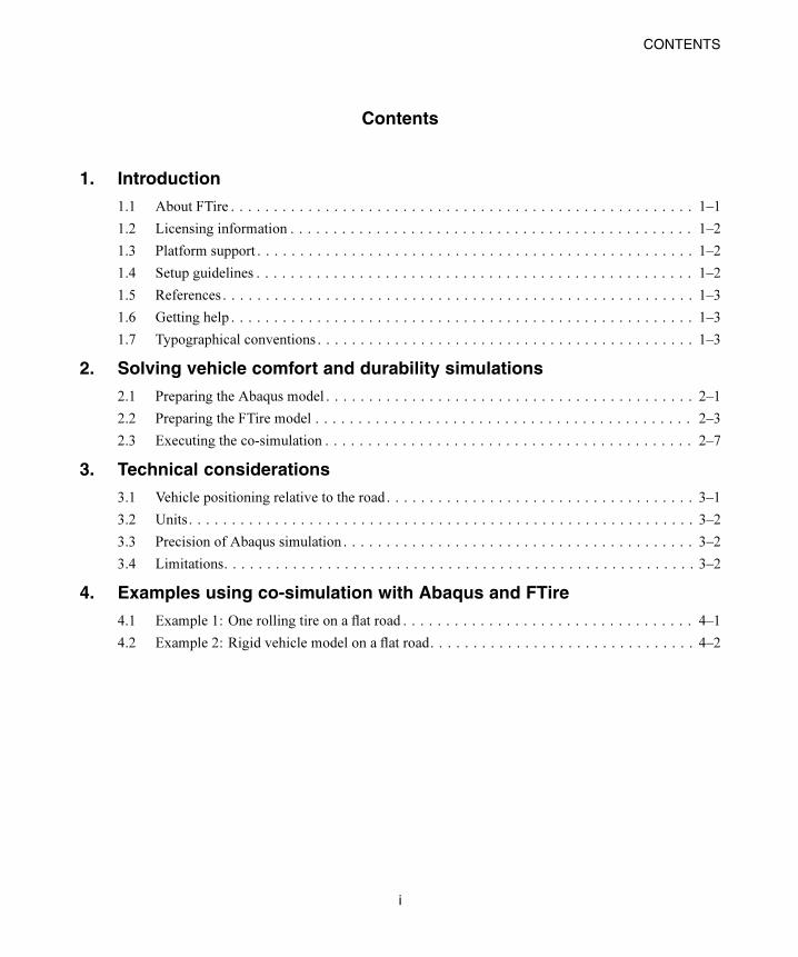
CONTENTS
Contents
1. Introduction
1.1 About FTire . . . . . . . . . . . . . . . . . . . . . . . . . . . . . . . . . . . . . . . . . . . . . . . . . . . . . . 1–1
1.2 Licensing information . . . . . . . . . . . . . . . . . . . . . . . . . . . . . . . . . . . . . . . . . . . . . . . 1–2
1.3 Platform support . . . . . . . . . . . . . . . . . . . . . . . . . . . . . . . . . . . . . . . . . . . . . . . . . . . 1–2
1.4 Setup guidelines . . . . . . . . . . . . . . . . . . . . . . . . . . . . . . . . . . . . . . . . . . . . . . . . . . . 1–2
1.5 References . . . . . . . . . . . . . . . . . . . . . . . . . . . . . . . . . . . . . . . . . . . . . . . . . . . . . . . 1–3
1.6 Getting help . . . . . . . . . . . . . . . . . . . . . . . . . . . . . . . . . . . . . . . . . . . . . . . . . . . . . . 1–3
1.7 Typographical conventions . . . . . . . . . . . . . . . . . . . . . . . . . . . . . . . . . . . . . . . . . . . . 1–3
2. Solving vehicle comfort and durability simulations
2.1 Preparing the Abaqus model . . . . . . . . . . . . . . . . . . . . . . . . . . . . . . . . . . . . . . . . . . . 2–1
2.2 Preparing the FTire model . . . . . . . . . . . . . . . . . . . . . . . . . . . . . . . . . . . . . . . . . . . . 2–3
2.3 Executing the co-simulation . . . . . . . . . . . . . . . . . . . . . . . . . . . . . . . . . . . . . . . . . . . 2–7
3. Technical considerations
3.1 Vehicle positioning relative to the road . . . . . . . . . . . . . . . . . . . . . . . . . . . . . . . . . . . . 3–1
3.2 Units. . . . . . . . . . . . . . . . . . . . . . . . . . . . . . . . . . . . . . . . . . . . . . . . . . . . . . . . . . . 3–2
3.3 Precision of Abaqus simulation . . . . . . . . . . . . . . . . . . . . . . . . . . . . . . . . . . . . . . . . . 3–2
3.4 Limitations. . . . . . . . . . . . . . . . . . . . . . . . . . . . . . . . . . . . . . . . . . . . . . . . . . . . . . . 3–2
4. Examples using co-simulation with Abaqus and FTire
4.1 Example 1: One rolling tire on a flat road . . . . . . . . . . . . . . . . . . . . . . . . . . . . . . . . . . 4–1
4.2 Example 2: Rigid vehicle model on a flat road. . . . . . . . . . . . . . . . . . . . . . . . . . . . . . . 4–2
i
Abaqus ID:fti
Printed on: Mon October 20 -- 9:29:02 2014

INTRODUCTION
1. Introduction
The Abaqus co-simulation technique can be used to solve comfort and durability simulations of a vehicle
maneuvering on an uneven road. Maneuvers such as accelerating, braking, rolling, and skidding can be
modeled. The vehicle, its suspension, and wheel rims are modeled in Abaqus. The tire, the road, and the
movement of the tire on the road are modeled in FTire (Flexible Ring Tire Model). Abaqus computes
displacements and rotations associated with the forces and torques arising from the vehicle moving on
the road, which are computed by FTire. Most of the Abaqus features are available for use, including
nonlinear materials, nonlinear geometric effects, contact, and connectors. The complex tire phenomena
is based on a strictly mechanical, tribological, and thermodynamical basis in FTire.
1.1 About FTire
The Flexible Ring Tire Model (FTire) is a time-domain, nonlinear tire simulation model distributed and
supported by Cosin Scientific Software (www.cosin.eu). FTire is designed for ride comfort simulations,
road load prediction, and durability simulation. It is suitable for road irregularities exhibiting high
frequency and short wavelength excitation and provides a physically based, highly nonlinear, and
dynamic tire model based on a mechanical, tribological, and thermodynamical basis. Based on structural
dynamics, FTire is a spatial nonlinear in-plane and out-of-plane tire model for belt dynamics. It can
capture local contact patch pressure distribution, rolling resistance, side-wall contact, large camber
angles, and misuse scenarios for a frequency range up to 200 Hz, excited by short surface wavelengths,
mass imbalance, nonuniformity of tire and/or rim, air cavity vibrations, and irregular tread patterns.
The FTire tire model includes capabilities to handle
• imbalances by nonhomogeneous mass and stiffness distribution, radius variation, and local tread
wear;
• belt temperature distribution;
• air volume vibration;
• tire slipping on its rim for very large drive or brake torques;
• integrated flexible and/or viscoplastic rim model; and
• user-defined wear, temperature distribution, and rim flexibility models.
The FTire road/soil model includes
• full integration of the cosin/road digital road library with support for complex rigid time-invariant
and time-variant road surfaces; and
• full integration of the cosin/soil digital road library with support for flexible and deformable road
surfaces.
1–1
Abaqus ID:fti
Printed on: Mon October 20 -- 9:29:02 2014

INTRODUCTION
1.2 Licensing information
Co-simulation using Abaqus and FTire is an add-on analysis capability that uses the
SIMULIA Co-Simulation Engine (CSE) and requires software licenses for both Abaqus and FTire.
More information on licensing Abaqus can be found from the Licensing section of the Supportpage at www.3ds.com/simulia. For information on licensing FTire, contact Cosin Scientific Software
at www.cosin.eu.
1.3 Platform support
The latest product information and platform support for the Abaqus and FTire capability can be found
at www.3ds.com/support/certified-hardware/simulia-system-information/compatibility/co-simulation.
In most cases Abaqus is compatible with later versions of the operating system software; however, it is
usually not compatible with earlier versions. For the latest product information for FTire, see the Cosin
Scientific Software homepage (www.cosin.eu).
Abaqus and FTire do not have to be run on the same platform; a coupled simulation can be performed
across heterogeneous computer systems.
1.4 Setup guidelines
Before you start, you need to install the Abaqus and FTire products. For the latest information on software
compatibility, see the Co-simulation page at www.3ds.com/support/certified-hardware/simulia-system-
information/compatibility/co-simulation. It is important that you verify that each product is properly
installed.
To run a co-simulation between Abaqus and FTire, the following environment variables must be
defined:
Windows platforms
PATH
The path to the CTI libraries must be prepended to the PATH environment variable.
Linux platforms
LD_LIBRARY_PATH
Set to the path where the CTI libraries are located.
1–2
Abaqus ID:fti
Printed on: Mon October 20 -- 9:29:02 2014

INTRODUCTION
1.5 References
This section contains a list of reference material for co-simulation using Abaqus and FTire.
Abaqus
• Abaqus Analysis User’s Guide
• Abaqus Keywords Reference Guide
FTire
• FTire—Flexible Ring Tire Model: Modelization and Parameter Specification (see
www.cosin.eu)
1.6 Getting help
You can contact your local SIMULIA support office for technical assistance with problems. For the latest
information on vehicle comfort and durability simulation using Abaqus and FTire, consult the Dassault
Systèmes Knowledge Base at www.3ds.com/support/knowledge-base.
1.7 Typographical conventions
This guide adheres to a set of typographical conventions so that you can recognize actions and items.
The following list illustrates each of the conventions:
• Text you enter from the keyboard: abaqus
• Hyperlinks: www.3ds.com/simulia
• Text indicating that the user has a choice: filename
1–3
Abaqus ID:fti
Printed on: Mon October 20 -- 9:29:02 2014


SOLVING VEHICLE COMFORT AND DURABILITY SIMULATIONS
2. Solving vehicle comfort and durability simulations
This chapter provides details on how to prepare and run a vehicle comfort and durability simulation
using Abaqus and FTire. The Abaqus and FTire processes communicate with each other during run
time, exchanging solution fields at designated target times. The communication process is controlled by
the SIMULIA Co-Simulation Engine (CSE). The following processes exist:
Abaqus
Abaqus/Standard or Abaqus/Explicit can be used to model the vehicle, its suspension, and the wheel
rims. Abaqus can be run using multiple processors.
FTire
FTire models the tire, the road, and the movement of the tire on the road.
Co-Simulation Engine Director
The CSE Director process directs and controls the data exchange between Abaqus and FTire.
All three processes require input files. The Abaqus input file defines the vehicle model and must
include the necessary co-simulation options, as discussed in “Preparing the Abaqus model,” Section 2.1.
FTire typically requires a tire file defining the tire characteristics and a road file defining the road profile.
For models containing multiple tires, each tire may use a different tire and/or road files. The input to
the FTire process is defined through the FTire input file, as discussed in “Preparing the FTire model,”
Section 2.2.
The Co-Simulation Engine Director process requires a co-simulation configuration file, which
describes the co-simulation problem setup (e.g., the codes participating in the co-simulation and the
fields being exchanged between the codes). The co-simulation configuration file is an XML-format
file generated by the FTire process and uses information provided by the FTire input file. In most
circumstances, you do not need to be concerned with the details of the co-simulation configuration file.
This file is generated automatically, and the CSE Director process is started from the FTire process.
Optionally, you can generate and modify the configuration file and start all of the processes manually.
Typical workflows for starting the co-simulation are discussed in “Executing the co-simulation,”
Section 2.3.
2.1 Preparing the Abaqus model
The Abaqus input file defines the vehicle model, typically including its suspension and wheel rims. The
model is typically created by a preprocessing tool. Most of the Abaqus features, including nonlinear
material, large deformation and finite rotations, contact, and constraints, can be used in the model. Co-
simulation with FTire is supported for the implicit transient dynamic (*DYNAMIC) and explicit transient
dynamic (*DYNAMIC, EXPLICIT) procedures.
2–1
Abaqus ID:fti
Printed on: Mon October 20 -- 9:29:02 2014

SOLVING VEHICLE COMFORT AND DURABILITY SIMULATIONS
The vehicle is positioned as described in “Vehicle positioning relative to the road,” Section 3.1.
Communication of physical fields exchanged between Abaqus and FTire occurs through a point coupling
representing the wheel rim in the Abaqus model. For each wheel rim, a node set with a single node
needs to be defined on the *CO-SIMULATION REGION option. Abaqus computes the displacements,
rotations, velocities, and rotational velocities and exports these fields to FTire. FTire computes the forces
and torques, representing the loads on the rim due to the tire traveling on an irregular road, which it
exports to Abaqus.
The example below illustrates the co-simulation options required for an Abaqus model that includes
four tires (Front-Left, Front-Right, Rear-Left, and Rear-Right).
…
*NSET, NAME=Front-Left
node number for front left wheel rim
*NSET, NAME=Front-Right
node number for front right wheel rim
*NSET, NAME=Rear-Left
node number for rear left wheel rim
*NSET, NAME=Rear-Right
node number for rear right wheel rim
…
*STEP, NLGEOM
*DYNAMIC(, EXPLICIT)
…
*CO-SIMULATION, PROGRAM=MULTIPHYSICS
*CO-SIMULATION REGION, TYPE=NODE, IMPORT
Front-Left, CF, CM
Front-Right, CF, CM
Rear-Left, CF, CM
Rear-Right, CF, CM
*CO-SIMULATION REGION, TYPE=NODE, EXPORT
Front-Left, UT, UR, VT, VR
Front-Right, UT, UR, VT, VR
Rear-Left, UT, UR, VT, VR
Rear-Right, UT, UR, VT, VR
…
*END STEP
Refer to Chapter 17, “Co-simulation,” of the Abaqus Analysis User’s Guide, for further information
about the co-simulation capability in Abaqus.
In addition, you need to define additional mass and rotary inertia properties for the rim in the Abaqus
model that are not accounted for by the tire model. The additional mass and inertia properties are printed
2–2
Abaqus ID:fti
Printed on: Mon October 20 -- 9:29:02 2014

SOLVING VEHICLE COMFORT AND DURABILITY SIMULATIONS
in the FTire message (.msg) files. An example of the printout is shown below for the _default.tir
file provided on the FTire release media.
MASS AND INERTIA CORRECTION IN MBS MODEL
*either add* the following mass properties to the rim in
your suspension model ('rim-fixed' tire parts which are
not accounted for in the tire model):
m = 3.577 kg
Ixx = Izz = 0.115 kgm^2
Iyy = 0.174 kgm^2 (y-axis = wheel rotation axis)
*or subtract* the following mass properties from the wheel
(=rim+tire) in your suspension model ('free' tire parts which
are accounted for in the tire model):
m = 4.523 kg
Ixx = Izz = 0.206 kgm^2
Iyy = 0.412 kgm^2 (y-axis = wheel rotation axis)
2.2 Preparing the FTire model
The FTire model file associates each tire rim defined in the Abaqus model with a tire file that describes
the tire properties and with a road file that describes the road profile. Typically, for vehicle comfort
and durability simulation only one tire file and one road file are needed to describe the tire properties
and the road. Under certain circumstances, different tire files (for example, when modeling a spare tire)
or a different road file (for example, when modeling a pothole) may be assigned to a tire. In addition,
information for vehicle placement and orientation with respect to the road may be specified in the FTire
model file, in which case the vehicle is positioned relative to the road. Alternatively, the road may be
positioned under the vehicle through the tire and road files; this condition is not discussed in this guide.
The information contained in the FTire model file is used to generate the Co-Simulation Engine
Director configuration file, and, hence, the FTire model file also includes input related to the Abaqus
solver and coupling scheme.
The FTire model file consists of data blocks that must comply with the following rules:
• Each data block is defined by the block name placed within square brackets (e.g., [MODEL]
represents the model data block).
• One or more data lines specifying variable/value pairs may follow the block header.
• The variable and value are always separated by an equal sign (e.g., TIRE=FRONT-RIGHT).
• Variable/value pairs are always separated by a comma or space (e.g., TIRE=FRONT-RIGHT,
TIREFILE=_default.tir).
• Each data block must end with an empty line.
2–3
Abaqus ID:fti
Printed on: Mon October 20 -- 9:29:02 2014

SOLVING VEHICLE COMFORT AND DURABILITY SIMULATIONS
2.2.1 [ABAQUS SOLVER] block
The [ABAQUS SOLVER] block defines whether Abaqus/Standard or Abaqus/Explicit is being used and
specifies the Abaqus job name. In addition, this block provides information regarding the orientation of
the vehicle in the Abaqus model.
JOB
Set JOB equal to the Abaqus job name without any file extension. The Abaqus job option may be
different from the Abaqus input option used when launching Abaqus (e.g., abaqus job=blowout
input=car). The job name is case sensitive.
LOCKSTEP
Set LOCKSTEP=FALSE (default) to allow Abaqus to take one or more increments between target
times. Set LOCKSTEP=TRUE to force Abaqus to use a single increment to reach the next target
time. Using lockstep enforces a severe condition; if Abaqus needs to cut back due to some event
(e.g., contact or plasticity), it must terminate with an error because a cut back is not allowed.
SOLVER
Set SOLVER=STANDARD to perform an implicit transient dynamic simulation using
Abaqus/Standard, or set SOLVER=EXPLICIT to perform an explicit transient dynamic
simulation using Abaqus/Explicit. The solver variable is a required variable.
2.2.2 [MODEL] block
The [MODEL] block associates each rim in the Abaqus model with a tire file and a road file. It also
provides information regarding the tire position normal to the road. For each tire provide a data line
defining the variables listed below.
OFFSET
Set OFFSET equal to the distance normal to the road that the tire is initially positioned. Specify the
offset distance in meters. Typically, the offset is a negative value indicating that the tire is deformed
due to the weight of the vehicle. At the start of the co-simulation, FTire will perform a steady-state
solution to compute the exact forces due to this offset. The default offset is 0, indicating that the
tire is placed on the road.
ROADFILE
Set ROADFILE equal to the name of the road file that defines the road properties. The ROADFILE
variable is a required variable. Its value is case sensitive on case-sensitive operating systems. You
must provide the file extension. It is expected that the road file is located in the directory where the
FTire process is started.
2–4
Abaqus ID:fti
Printed on: Mon October 20 -- 9:29:02 2014

SOLVING VEHICLE COMFORT AND DURABILITY SIMULATIONS
TIRE
Set TIRE equal to the node set name that defines the rim in the Abaqus model. The TIRE variable
is a required variable, and its value is case insensitive; that is, Front-Right and FRONT-RIGHT
refer to the same node set in the Abaqus model.
TIREFILE
Set TIREFILE equal to the name of the tire file that defines the tire properties. The TIREFILE
variable is a required variable. Its value is case sensitive on case-sensitive operating systems. You
must provide the file extension. It is expected that the tire file is located in the directory where the
FTire process is started.
2.2.3 [SCENARIO] blockThe [SCENARIO] block defines the duration of the event/scenario being modeled.
DURATION
Set DURATION equal to the duration of the co-simulation event being modeled. The DURATION
variable is a required variable, and it must match the total time specified on the Abaqus procedure
option.
STARTTIME
Set STARTTIME equal to the start time of the co-simulation event. The start time is not used
currently and can be set to 0 (default).
2.2.4 [UNITS] blockAbaqus supports a consistent unit system; that is, any units can be used as long as all quantities have been
defined using a consistent unit system. FTire uses the SI unit system. The [UNITS] block specifies unit
conversion factors that convert units used in the Abaqus model to the SI unit system.
FORCE
Set FORCE equal to the factor to scale the force unit in Abaqus to Newtons. The default value is 1,
indicating that the Abaqus model is using SI units.
LENGTH
Set LENGTH equal to the factor to scale the length unit in Abaqus to meters. The default value is 1,
indicating that the Abaqus model is using SI units.
MASS
Set MASS equal to the factor to scale the mass unit in Abaqus to kilograms. The default value is 1,
indicating that the Abaqus model is using SI units.
2–5
Abaqus ID:fti
Printed on: Mon October 20 -- 9:29:02 2014

SOLVING VEHICLE COMFORT AND DURABILITY SIMULATIONS
TIME
Set TIME equal to the factor to scale the time unit in Abaqus to seconds. The default value is 1,
indicating that the Abaqus model is using SI units. The time units must always be set to 1, indicating
that seconds are used, which is a current limitation.
2.2.5 [COUPLING SCHEME] blockThe [COUPLING SCHEME] block allows you to control the coupling algorithm.
COUPLINGSCHEME
Set COUPLINGSCHEME=GAUSS-SEIDEL (default) to have Abaqus and FTire execute in tandem.
Set COUPLINGSCHEME=JACOBI to have Abaqus and FTire run concurrently.
MAXEXCHANGES
Set MAXEXCHANGES to the number of exchanges to be performed at the coupling target time
to provide a more stable solution by employing an iterative implicit coupling scheme. Set
MAXEXCHANGES=0 to select an explicit coupling scheme. The default value is 1, enabling a
predictor/corrector scheme with one additional exchange at the target time. MAXEXCHANGES has
no effect when Abaqus/Explicit is used.
2.2.6 [NEGOTIATION SCHEME] blockThe [NEGOTIATION SCHEME] block allows you to control the synchronization method employed
for establishing target times.
DT
Set DT equal to the time step size used when NEGOTIATIONSCHEME=CONSTANTDT. The default
value is 1 ms.
NEGOTIATIONSCHEME
Set NEGOTIATIONSCHEME=CONSTANTDT to use a constant time step size defined by
DT to establish the next target time. In this case you must specify the DT variable. Set
NEGOTIATIONSCHEME=ABAQUS to have Abaqus define the target times based on its next
preferred increment size.
2.2.7 Example: FTire input fileThe following example illustrates the format of an FTire input file. Four tires are modeled in Abaqus
with the node set labels FL, FR, RL, and RR. We assume that the rear left (RL) tire uses a spare whose tire
properties are defined by spare.tir and that the remaining tires use properties defined by oem.tir.
2–6
Abaqus ID:fti
Printed on: Mon October 20 -- 9:29:02 2014

SOLVING VEHICLE COMFORT AND DURABILITY SIMULATIONS
A single road file (road.rdf) is used for all four tires. An offset of –15 mm is specified to describe
the footprint due to the vehicle’s weight. A Gauss-Seidel, implicit iterative scheme is selected with one
additional coupling exchange per coupling step. A constant negotiation scheme with a time increment
size of 0.0001 seconds is specified. The Abaqus model uses the SI unit system, and the scenario duration
is 2 seconds.
[ABAQUS SOLVER]
SOLVER=STANDARD, JOB=Job-1, LOCKSTEP=FALSE
[MODEL]
TIRE=FL, TIREFILE=oem.tir, ROADFILE=road.rdf, OFFSET=-0.015
TIRE=FR, TIREFILE=oem.tir, ROADFILE=road.rdf, OFFSET=-0.015
TIRE=RL, TIREFILE=spare.tir, ROADFILE=road.rdf, OFFSET=-0.015
TIRE=RR, TIREFILE=oem.tir, ROADFILE=road.rdf, OFFSET=-0.015
[SCENARIO]
STARTTIME=0.0, DURATION=2.0
[COUPLING SCHEME]
COUPLINGSCHEME=GAUSS-SEIDEL, MAXEXCHANGES=1
[NEGOTIATION SCHEME]
NEGOTIATIONSCHEME=CONSTANTDT, DT=0.0001
[UNITS]
LENGTH=1.0, FORCE=1.0, MASS=1.0, TIME=1.0
2.3 Executing the co-simulation
As discussed above, co-simulation between Abaqus and FTire runs three processes and requires
input files for each process. For typical applications, the Co-Simulation Engine configuration file
is created from the FTire input file automatically, and the Co-Simulation Engine Director process
is launched automatically. Advanced users may need to modify the configuration file; for example,
when performing n-code coupling between Abaqus, FTire, and additional solvers. In this case you can
generate the configuration file using a datacheck and revise the file; then, all three processes must be
launched manually.
This section summarizes the command line options of the FTire process and provides examples for
running typical and advanced applications.
2–7
Abaqus ID:fti
Printed on: Mon October 20 -- 9:29:02 2014

SOLVING VEHICLE COMFORT AND DURABILITY SIMULATIONS
2.3.1 FTire command line optionsThe following options can be specified when starting FTire:
cseconfigfile
Option to specify the name of the Co-Simulation Engine configuration file. This option is required
when the manualLaunch option is specified.
datacheck
Option used to perform a data check only. During a data check, the FTire model file is read and the
Co-Simulation Engine configuration file is generated.
input
Required option to specify the name of the FTire model file. The file name, including the file
extension, must be provided. The file name is case sensitive on case-sensitive operating systems. It
is expected that the file is located in the directory where the FTire process is started.
manualLaunch
Option used to launch FTire manually. For launching manually both the cseconfigfile and
port options must be provided.
port
Option used to specify the TCP/UDP port number for co-simulation inbound messages to the
director. Set port equal to the port number used for the connection. If not specified, a random port
between the range of 4000 and 6000 is selected. This option is required when the manualLaunch
option is specified.
timeout
Option used to specify a timeout value in seconds for the co-simulation director connection. FTire
terminates if it does not receive any communication from the CSE Director process during the time
specified. The default value is 3600 seconds.
verbose
Option used to specify the verbosity level for debug output. If the level is 0 (default), no debug
output is generated.
2.3.2 Example: Typical applicationsThis example shows the command for executing the co-simulation for most applications. You start the
FTire job, which generates the Co-Simulation Engine configuration file and launches the Co-simulation
2–8
Abaqus ID:fti
Printed on: Mon October 20 -- 9:29:02 2014

SOLVING VEHICLE COMFORT AND DURABILITY SIMULATIONS
Engine Director process automatically. In this example we assume that the FTire input file is named
pothole_ftire.inp.
To execute the co-simulation for typical applications:
1. Enter the following command to start the FTire job:
abaqus ftire input=pothole_ftire.inp
The Co-Simulation Engine configuration file is generated, and the Co-simulation Engine Director
process is launched.
2. Start the Abaqus job using the instructions provided in the message printed to the command window.
2.3.3 Example: Advanced applicationsThis example shows the commands required for executing the co-simulation for advanced applications.
You must generate the CSE Director process input file (Co-Simulation Engine configuration file)
separately and launch the Abaqus, FTire, and the CSE Director processes manually. In this example, we
assume that
• the Abaqus input file is named vehicle_xpl.inp,
• Abaqus is launched using two cpus,
• Abaqus/Explicit uses double precision (recommended for co-simulations),
• the CSE Director process is started on host mercury using port 4444,
• the FTire input file is named wheels_ftire.inp, and
• the configuration file is named wheels_ftire_config.xml.
To execute the co-simulation for advanced applications:
1. Enter the following command to perform a data check and generate the configuration file:
abaqus ftire input=wheels_ftire.inp datacheck
A configuration file named wheels_ftire_config.xml is created.
2. Revise the configuration file as needed.
3. Launch the Abaqus, FTire, and the CSE Director processes manually.
a. Enter the following command to start the Abaqus job:
abaqus job=vehicle_xpl input=wheels_ftire
csedirector=mercury:4444 cpus=2 double
b. Enter the following command to start the FTire job:
abaqus ftire input=wheels_ftire.inp port=4444
2–9
Abaqus ID:fti
Printed on: Mon October 20 -- 9:29:02 2014

SOLVING VEHICLE COMFORT AND DURABILITY SIMULATIONS
manualLaunch cseconfigfile=wheels_ftire_config.xml
c. Enter the following command to start the Co-Simulation Engine Director process:
abaqus cse job=director listenerport=4444
configure=wheels_ftire_config.xml
2–10
Abaqus ID:fti
Printed on: Mon October 20 -- 9:29:02 2014
TECHNICAL CONSIDERATIONS
3. Technical considerations
This section discusses some technical consideration and limitations when performing vehicle comfort
and durability simulation using Abaqus and FTire.
3.1 Vehicle positioning relative to the road
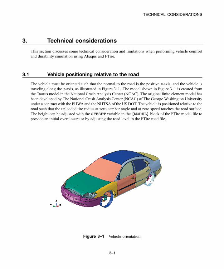
The vehicle must be oriented such that the normal to the road is the positive z-axis, and the vehicle is
traveling along the x-axis, as illustrated in Figure 3–1. The model shown in Figure 3–1 is created from
the Taurus model in the National Crash Analysis Center (NCAC). The original finite element model has
been developed by The National Crash Analysis Center (NCAC) of The George Washington University
under a contract with the FHWA and the NHTSA of the US DOT. The vehicle is positioned relative to the
road such that the unloaded tire radius at zero camber angle and at zero speed touches the road surface.
The height can be adjusted with the OFFSET variable in the [MODEL] block of the FTire model file to
provide an initial overclosure or by adjusting the road level in the FTire road file.
Figure 3–1 Vehicle orientation.
3–1
Abaqus ID:fti
Printed on: Mon October 20 -- 9:29:02 2014

TECHNICAL CONSIDERATIONS
3.2 Units
Abaqus uses a consistent unit system; that is, any unit system may be chosen as long as all units are
specified consistently in the Abaqus model. FTire uses the SI unit system. Use the [UNITS] block in
the FTire input file to provide length, force, mass, and time factors to convert from Abaqus units to the
SI unit system. The time units must be specified in seconds, which is a current limitation.
3.3 Precision of Abaqus simulation
To avoid numerical issues, it is highly recommended that Abaqus/Explicit use double precision.
3.4 Limitations
See the Abaqus Analysis User’s Guide for general limitations regarding co-simulation. In addition to
these limitations, the following limitations exist when coupling Abaqus with FTire:
• Restart analysis is not supported.
• All tires must be defined and executed in a single instance of the FTire code. Multiple FTire codes
cannot be coupled with Abaqus.
• FTire co-simulation cannot be defined in more than two steps in one input file.
3–2
Abaqus ID:fti
Printed on: Mon October 20 -- 9:29:02 2014

EXAMPLES USING CO-SIMULATION WITH Abaqus AND FTire
4. Examples using co-simulation with Abaqus and FTire
Two examples are provided for using co-simulation with Abaqus and FTire.
• “Example 1: One rolling tire on a flat road,” Section 4.1
• “Example 2: Rigid vehicle model on a flat road,” Section 4.2
4.1 Example 1: One rolling tire on a flat road
In this example, the model has only one tire rolling on a flat road. The wheel center is fixed except for the
rolling direction and the moving direction. The initial translational and rotational velocities are assigned
to the wheel center. The purpose of this analysis is to confirm that the co-simulation between Abaqus
and FTire performs correctly.
In the Abaqus model, only point mass and rotary inertia are modeled. The node on the point mass
and rotary inertia element are attached to FTire. In the FTire model, the default tire and flat road files in
the FTire example directory are used.
4.1.1 Example 1: FilesThe following files are used in this example:
• Abaqus_one_tire_rolling.inp: Abaqus input file
• FTire_one_tire_rolling.inp: FTire input file for FTire co-simulation
• _default.tir: FTire tire property input file
• _default.rdf: FTire road input file
4.1.2 Example 1: CommandsThe following commands are used to run the Abaqus and FTire co-simulation:
abaqus job=Abaqus_one_tire_rolling csedirector=localhost:4000
interactive
abaqus ftire input=FTire_one_tire_rolling.inp port=4000
4.1.3 Example 1: ValidationThe validation can be done by observing the tire animation and the reaction force at the wheel center.
In the example file, the total mass of the Abaqus model (wheel) is set to 10 kg. Considering CF3 and
4–1
Abaqus ID:fti
Printed on: Mon October 20 -- 9:29:02 2014
EXAMPLES USING CO-SIMULATION WITH Abaqus AND FTire
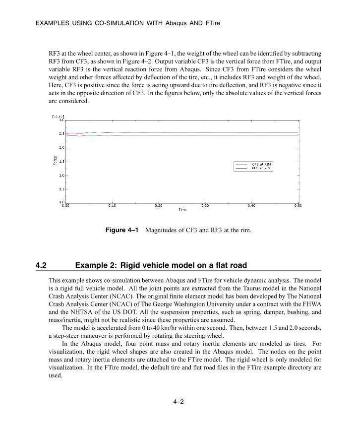
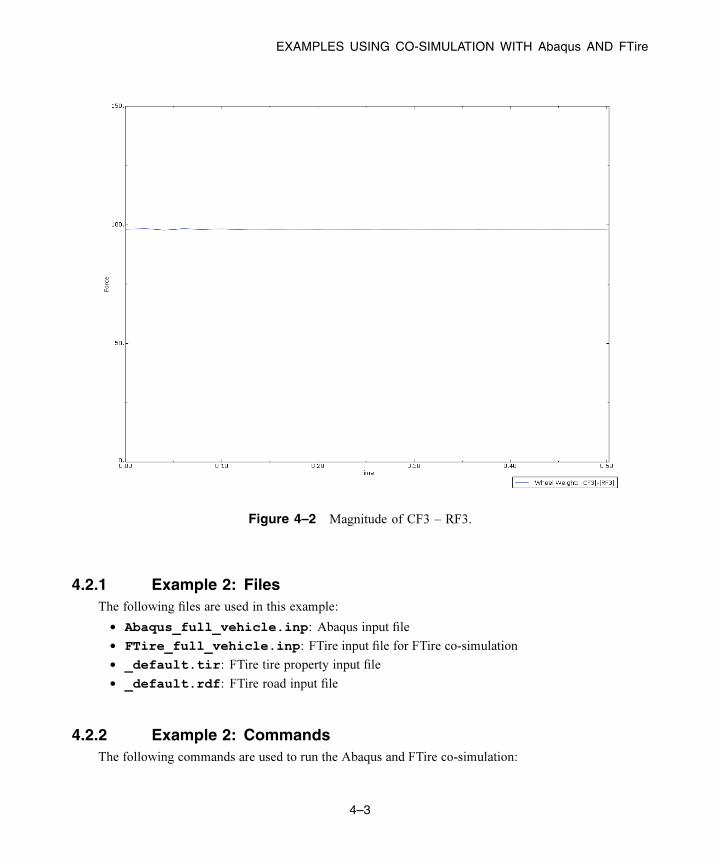
RF3 at the wheel center, as shown in Figure 4–1, the weight of the wheel can be identified by subtracting
RF3 from CF3, as shown in Figure 4–2. Output variable CF3 is the vertical force from FTire, and output
variable RF3 is the vertical reaction force from Abaqus. Since CF3 from FTire considers the wheel
weight and other forces affected by deflection of the tire, etc., it includes RF3 and weight of the wheel.
Here, CF3 is positive since the force is acting upward due to tire deflection, and RF3 is negative since it
acts in the opposite direction of CF3. In the figures below, only the absolute values of the vertical forces
are considered.
Figure 4–1 Magnitudes of CF3 and RF3 at the rim.
4.2 Example 2: Rigid vehicle model on a flat road
This example shows co-simulation between Abaqus and FTire for vehicle dynamic analysis. The model
is a rigid full vehicle model. All the joint points are extracted from the Taurus model in the National
Crash Analysis Center (NCAC). The original finite element model has been developed by The National
Crash Analysis Center (NCAC) of The George Washington University under a contract with the FHWA
and the NHTSA of the US DOT. All the suspension properties, such as spring, damper, bushing, and
mass/inertia, might not be realistic since these properties are assumed.
The model is accelerated from 0 to 40 km/hr within one second. Then, between 1.5 and 2.0 seconds,
a step-steer maneuver is performed by rotating the steering wheel.
In the Abaqus model, four point mass and rotary inertia elements are modeled as tires. For
visualization, the rigid wheel shapes are also created in the Abaqus model. The nodes on the point
mass and rotary inertia elements are attached to the FTire model. The rigid wheel is only modeled for
visualization. In the FTire model, the default tire and flat road files in the FTire example directory are
used.
4–2
Abaqus ID:fti
Printed on: Mon October 20 -- 9:29:02 2014
EXAMPLES USING CO-SIMULATION WITH Abaqus AND FTire
Figure 4–2 Magnitude of CF3 – RF3.
4.2.1 Example 2: FilesThe following files are used in this example:
• Abaqus_full_vehicle.inp: Abaqus input file
• FTire_full_vehicle.inp: FTire input file for FTire co-simulation
• _default.tir: FTire tire property input file
• _default.rdf: FTire road input file
4.2.2 Example 2: CommandsThe following commands are used to run the Abaqus and FTire co-simulation:
4–3
Abaqus ID:fti
Printed on: Mon October 20 -- 9:29:02 2014
EXAMPLES USING CO-SIMULATION WITH Abaqus AND FTire
abaqus job=Abaqus_ full_vehicle csedirector=localhost:4000
interactive
abaqus ftire input=FTire_ full_vehicle.inp port=4000
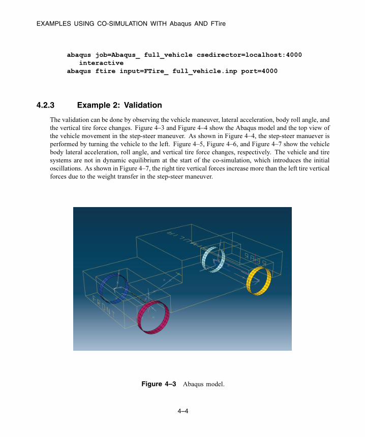
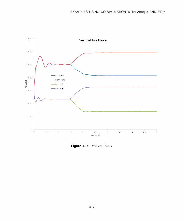
4.2.3 Example 2: Validation
The validation can be done by observing the vehicle maneuver, lateral acceleration, body roll angle, and
the vertical tire force changes. Figure 4–3 and Figure 4–4 show the Abaqus model and the top view of
the vehicle movement in the step-steer maneuver. As shown in Figure 4–4, the step-steer manuever is
performed by turning the vehicle to the left. Figure 4–5, Figure 4–6, and Figure 4–7 show the vehicle
body lateral acceleration, roll angle, and vertical tire force changes, respectively. The vehicle and tire
systems are not in dynamic equilibrium at the start of the co-simulation, which introduces the initial
oscillations. As shown in Figure 4–7, the right tire vertical forces increase more than the left tire vertical
forces due to the weight transfer in the step-steer maneuver.
Figure 4–3 Abaqus model.
4–4
Abaqus ID:fti
Printed on: Mon October 20 -- 9:29:02 2014

EXAMPLES USING CO-SIMULATION WITH Abaqus AND FTire
Figure 4–4 Step-steer maneuver of the Abaqus model.
Figure 4–5 Vehicle body lateral acceleration.
4–5
Abaqus ID:fti
Printed on: Mon October 20 -- 9:29:02 2014

EXAMPLES USING CO-SIMULATION WITH Abaqus AND FTire
Figure 4–6 Vehicle body roll angle.
4–6
Abaqus ID:fti
Printed on: Mon October 20 -- 9:29:02 2014
EXAMPLES USING CO-SIMULATION WITH Abaqus AND FTire
Figure 4–7 Vertical forces.
4–7
Abaqus ID:fti
Printed on: Mon October 20 -- 9:29:02 2014


About SIMULIADassault Systèmes SIMULIA applications, including Abaqus, Isight, Tosca, and Simulation Lifecycle Management, enable users to leverage physics-based simulation and high-performance computing to explore real-world behavior of products, nature, and life. As an integral part of Dassault Systèmes’ 3DEXPERIENCE platform, SIMULIA applications accelerate the process of making highly informed, mission-critical design and engineering decisions before committing to costly and time-consuming physical prototypes. www.3ds.com/simulia
Europe/Middle East/AfricaDassault Systèmes10, rue Marcel DassaultCS 4050178946 Vélizy-Villacoublay CedexFrance
AmericasDassault Systèmes175 Wyman StreetWaltham, Massachusetts02451-1223USA
Asia-PacificDassault Systèmes K.K.ThinkPark Tower2-1-1 Osaki, Shinagawa-ku,Tokyo 141-6020Japan
Our 3DEXPERIENCE Platform powers our brand applications, serving 12 industries, and provides a rich portfolio of industry solution experiences. Dassault Systèmes, the 3DEXPERIENCE Company, provides business and people with virtual universes to imagine sustainable innovations. Its world-leading solutions transform the way products are designed, produced, and supported. Dassault Systèmes’ collaborative solutions foster social innovation, expanding possibilities for the virtual world to improve the real world. The group brings value to over 170,000 customers of all sizes in all industries in more than 140 countries. For more information, visit www.3ds.com.
©20
14 D
assa
ult S
ystè
mes
. All
righ
ts re
serv
ed. 3
DEX
PER
IENCE
, the
Com
pass
icon
and
the
3DS
logo
, CA
TIA
, SO
LID
WO
RKS
, EN
OVI
A, D
ELM
IA, S
IMU
LIA
, GEO
VIA
, EXA
LEA
D, 3
D V
IA, B
IOVI
A, N
ETVI
BES
, and
3D
XCIT
E ar
e co
mm
erci
al tr
adem
arks
or
regi
ster
ed tr
adem
arks
of D
assa
ult S
ystè
mes
or i
ts s
ubsi
diar
ies
in th
e U
.S. a
nd/o
r oth
er c
ount
ries
. All
othe
r tra
dem
arks
are
ow
ned
by th
eir r
espe
ctiv
e ow
ners
. Use
of a
ny D
assa
ult S
ystè
mes
or i
ts s
ubsi
diar
ies
trad
emar
ks is
sub
ject
to th
eir e
xpre
ss w
ritt
en a
ppro
val.