AB2588 Air Toxics Emission Inventory Plan (Dec 2013)
69
AB2588 Air Toxics Emission Inventory Plan Exxon – SYU Stationary Source Los Flores Canyon Oil & Gas Plant And POPCO Gas Plant Emissions Reporting Year: 2013 Submitted to: Santa Barbara County Air Pollution Control District 260 North San Antonio Road, Suite A Santa Barbara, CA 93110 Submitted by: ExxonMobil Production P.O. Box 4358 Houston, TX 77210-4358 December 2013
Transcript of AB2588 Air Toxics Emission Inventory Plan (Dec 2013)

AB2588 Air Toxics Emission Inventory Plan
Exxon – SYU Stationary Source
Los Flores Canyon Oil & Gas Plant
And
POPCO Gas Plant
Emissions Reporting Year: 2013
Submitted to:
Santa Barbara County Air Pollution Control District
260 North San Antonio Road, Suite A
Santa Barbara, CA 93110
Submitted by:
ExxonMobil Production
P.O. Box 4358
Houston, TX 77210-4358
December 2013

i
Table of Contents
1 Industry Contact Information ............................................................................................ 1
2 Introduction ....................................................................................................................... 2
3 Detailed Facility Information ............................................................................................. 5
3.1 Las Flores Canyon Facility ........................................................................................... 5
3.2 POPCO Facility .......................................................................................................... 16
4 Emission Estimation Techniques and Proposals.............................................................. 21
4.1 Las Flores Canyon Facility ......................................................................................... 21
4.2 POPCO Gas Plant ...................................................................................................... 38
5 Source Modeling Parameters ........................................................................................... 45
5.1 Las Flores Canyon .................................................................................................... 45
5.2 POPCO Gas Plant ...................................................................................................... 55
5.3 Las Flores Canyon/POPCO Facility Location ............................................................. 59
5.4 Las Flores Canyon/POPCO Building Tier Heights and UTM Coordinates ................. 61
6 Schedule for ATEIR........................................................................................................... 65
7 References ....................................................................................................................... 66
Appendix A – LFC and POPCO Process Stream Data
Appendix B – LFC and POPCO Stream Sample Locations
Appendix C – Emission Estimation Techniques – Supporting Data
Appendix D – Source Test Data
Appendix E – Emission Factor Documentation
Appendix F – Material Safety Data Sheets (MSDS)
Appendix G – Modeling Parameters – Building Height and Coordinate Details
Appendix H – LFC Fugitive Hydrocarbon Component Grouping by Plant Area and Process
Stream
Appendix I– POPCO Fugitive Hydrocarbon Component Grouping by Plant Area and Process
Stream
1
1 Industry Contact Information
AB2588 Air Toxics Emission Inventory Plan for Emissions Year 2013
Submitted to:
Santa Barbara County Air Pollution Control District
260 North San Antonio Road, Suite A
Santa Barbara, CA 93110
Attn: Robin Cobbs
Submitted by:
ExxonMobil Production
P.O. Box 4358
Houston, TX 77210-4358
Company Contact: Mr. Mark Decatur
Regulatory Compliance Supervisor
(713) 431-1491
Submitted For:
Exxon – SYU Stationary Source (Los Flores Canyon and POPCO Plants)
12000 Calle Real
Goleta, CA 93117
Name: Mr. Mark Decatur Title: Regulatory Compliance Supervisor
Signed:
Date:

2
2 Introduction
The Las Flores Canyon and POPCO facilities are part of the Exxon – SYU Project stationary
source. The Exxon - SYU Project stationary source consists of five facilities, three of which
are platforms located in the outer continental shelf, not subject to review under AB2588.
ExxonMobil Production Company (“ExxonMobil”), an unincorporated division of Exxon
Mobil Corporation, owns and operates the Las Flores Canyon facility. Pacific Offshore
Pipeline Company (“POPCO”), a subsidiary of Exxon Mobil Corporation, owns the POPCO
facility, while ExxonMobil operates the facility.
The onshore facilities are located in Las Flores Canyon (“LFC”) approximately 20 miles west
of Santa Barbara, California in the southwestern part of Santa Barbara County. The
ExxonMobil property consists of a pie-shaped piece of property, approximately 1500 acres,
starting on the north side of Highway 101 and continuing to the north. Of this area,
approximately 110 acres have been cleared with 34 acres containing facilities and the
remainder left as open space. A paved road about 1.5 miles long from Calle Real, the
frontage road off Highway 101, provides access to the facility. Within the ExxonMobil
property, approximately 17 acres is leased to Pacific Offshore Pipeline Company (“POPCO”)
to operate a natural gas treating facility. In addition, small areas are provided for
installation of utility connections by Southern California Gas Company (“SCG”) and Southern
California Edison Company (“SCE”) as well as a pump station by the All American Pipeline
Company for crude transportation.
The Santa Ynez Unit (“SYU”) Project develops production from three platforms (Platforms
Hondo, Harmony and Heritage) located offshore California in the Santa Barbara Channel.
The production is transported to shore through a subsea pipeline and treated in the
production facilities located in Las Flores Canyon. The LFC facility treats the oil, gas, and
other by-products to acceptable product quality specifications prior to shipment by pipeline
or truck to their destinations. The onshore LFC facility is subdivided into the following
plants:
• Oil Treating Plant (“OTP”)
• Stripping Gas Treating Plant (“SGTP”)
• Transportation Terminal (“TT”)
• Cogeneration Power Plant (“CPP”)
The POPCO Gas Plant processes the majority of the natural gas produced by the SYU
Project. The POPCO Gas Plant receives the raw natural gas from the offshore platforms via
the 12-inch produced gas pipeline. The Gas Plant produces PUC quality natural gas,
propane, butane and sulfur products for sale. The recovered produced water is treated to
acceptable standards and returned to Platform Harmony for release to the ocean in
accordance with NPDES permit No. CA0110842.
3
Please see Part 70/APCD PTO 5651 and Part 70/APCD PTO 8092 for additional details
pertaining to the operation of these facilities.

4
Figure 2-1 Aerial View of Las Flores Canyon and POPCO Facilities

5
3 Detailed Facility Information
3.1 Las Flores Canyon Facility
Tables 3-1, 3-2, 3-3, and 3-4 provide a list of the emitting equipment at Las Flores Canyon,
organized into four groups based on the plant within the facility that the equipment is
located at. The table identifies the device, APCD Device No, the new Device No. assigned by
ExxonMobil to be used in the ATEIR, along with the AB2588 substances that may be
quantified for each device. The emission points in these tables are taken from the past
ATEIR, and Table 5.1 and section 10.5 of Part 70/PTO 5651.
As noted in Tables 3-1 through 3-4, some of the substances which CARB has identified for
emission quantification under the AB2588 program have not been assigned risk assessment
health values by OEHHA and CARB (OEHHA/CARB, 2013). ExxonMobil has included these
substances in Tables 3-1 through 3-4 should OEHHA and CARB define risk assessment values
in the future; however they will not be included in the emission estimates or modeling
associated with the 2013/2014 ATEIR.
The AB2588 program includes equipment that is already under permit by the Santa Barbara
APCD, as well as equipment that is exempt from APCD permitting. Permitted equipment
has an APCD Device No. associated with it, whereas exempt equipment may not. A new
numbering system has been defined for this ATEIP such that all equipment are identified
using a common numbering system. The basic structure for the new system is as follows:
• Device Identification Numbers:
o 6-digit unique device identification number for each piece of equipment and
operating mode;
o Incorporates ExxonMobil’s existing Equipment Operator ID
o Point Sources: 1XXXXX
o Area Sources: 2XXXXX
o Volume Sources: 3XXXXX
• Stack Identification Numbers:
o 5-digit unique stack identification number. This number is shared for devices with
multiple operating modes or which vent through a common stack
Figures 3-1 through 3-4 include diagrams of each of the four plant areas within the Las
Flores Canyon facilities. Each diagram identifies the associated point, volume, and area
sources of emissions.

6
Table 3-1 AB2588 Substances to be Quantified for Year 2013 Toxics Emission Inventory – LFC Cogeneration Power Plant
Device Name APCD
ID
Device
ID
Ace
tald
eh
yd
e
Acr
ole
in
Am
mo
nia
1,3
-bu
tad
ien
e
Be
nze
ne
Ca
rbo
ny
l S
ulf
ide
Ch
lori
ne
Ch
loro
be
nze
ne
Cy
clo
he
xa
ne
Die
sel
Pa
rtic
ula
te
Eth
yle
ne
Gly
cols
(D
EG
, E
G,
TE
G)
Die
thy
len
e G
lyco
l M
on
ob
uty
l
Eth
er
Eth
ylb
en
zen
e
Fo
rma
lde
hy
de
He
xa
ne
Hy
rdra
zin
e
Hy
dro
chlo
ric
Aci
d
Hy
dro
ge
n S
ulf
ide
Na
ph
tha
len
e
PA
Hs
Ph
osp
ho
ric
Aci
d
Pro
py
len
e
Pro
py
len
e O
xid
e
So
diu
m H
yd
rox
ide
Tri
me
thy
lbe
nze
ne
(1
,2,4
)
To
lue
ne
Xy
len
es
Me
tals
OEHHA RA Health Value?
���� ���� ���� ���� ���� N
o ���� ����
N
o ����
N
o
N
o ���� ���� ���� ���� ���� ���� ���� ���� ���� ���� ���� ����
N
o ���� ���� ����
Acid Skid 125060 x
Ammonia Storage Vessel and
Injection System 221050 x
Caustic Skid 225050 x
Cooling Water System 224060 x
CPP -- HRSG Only 7865 126022 x x x x x x x x x x x x x
CPP -- Normal Ops. Modes (GTG
and GTG/HRSG Ops.) 6585 126021 x x x x x x x x x x x x x
CPP - SU/SD Combined CPP &
Bypass Stacks 7866 125010 x x x x x x x x x x x x x
CPP Compressor Seals - Plant Wide 380222 x x x x x x x x x x x
CPP Fugitive Components (Gas) -
Plant Wide 360211 x x x x x x x x x x x x
CPP Fugitive Components (Oil) -
Plant Wide 360212 x x x x x x x x x x x x
CPP Maint. Abrasive Blasting -
Plant Wide 370211 x
CPP Maint. Painting & Coating -
Plant Wide 370212 x x x x
CPP Process Solvent Loss - Plant
Wide 390220 x x
CPP Pump Seals - Plant Wide 380221 x x x x x x x x x x x
Deaerator 121110 X
Steam Condensate System 221090 X
Steam Drum 221120 X
Steam System Chemical Injection
System 225020 X

7

8
Table 3-2 AB2588 Substances to be Quantified for Year 2013 Toxics Emission Inventory – LFC Stripping Gas Treating Plant
Device Name APCD ID Device
ID
Ace
tald
eh
yd
e
Acr
ole
in
Am
mo
nia
1,3
-bu
tad
ien
e
Be
nze
ne
Ca
rbo
ny
l S
ulf
ide
Ch
lori
ne
Ch
loro
be
nze
ne
Cy
clo
he
xa
ne
Die
sel
Pa
rtic
ula
te
Eth
yle
ne
Gly
cols
(DE
G,
EG
, T
EG
) D
ieth
yle
ne
Gly
col
Mo
no
bu
tyl
Eth
er
Eth
ylb
en
zen
e
Fo
rma
lde
hy
de
He
xa
ne
Hy
rdra
zin
e
Hy
dro
chlo
ric
Aci
d
Hy
dro
ge
n S
ulf
ide
Na
ph
tha
len
e
PA
Hs
Ph
osp
ho
ric
Aci
d
Pro
py
len
e
Pro
py
len
e O
xid
e
So
diu
m H
yd
rox
ide
Tri
me
thy
lbe
nze
ne
(1
,2,4
)
To
lue
ne
Xy
len
es
Me
tals
OEHHA RA Health Value? ���� ���� ���� ���� ���� N
o ���� ����
N
o ����
N
o
N
o ���� ���� ���� ���� ���� ���� ���� ���� ���� ���� ���� ����
N
o ���� ���� ����
Area Drain Oil/Water
Separator - SGTP 6578
144060 x x x x
Area Drain Sump - SGTP 6582 244050 x x x x
Fresh Caustic Day Tank 244120 x
Open Drain Sump - SGTP 6579 144070 x x x x
SGTP Compressor Seals -
Plant Wide
380422 x x x x x x x x x x x
SGTP Fugitive Components
(Gas) - Plant Wide
360411 x x x x x x x x x x x x
SGTP Fugitive Components
(Oil) - Plant Wide
360412 x x x x x x x x x x x x
SGTP Maint. Abrasive
Blasting - Plant Wide
370411 x
SGTP Maint. Painting &
Coating - Plant Wide
370412 x x x x
SGTP Process Solvent Loss -
Plant Wide
390420 x x
SGTP Pump Seals - Plant
Wide
380421 x x x x x x x x x x x
Waste Gas Incinerator --
Planned
SU/SD/Maintenance
7869
146032 x x x x x x
Waste Gas Incinerator
(w/out Merox) 7868
146031 x x x x x x

9

10
Table 3-3 AB2588 Substances to be Quantified for Year 2013 Toxics Emission Inventory – LFC Transportation Terminal
Device Name APCD ID Device
ID
Ace
tald
eh
yd
e
Acr
ole
in
Am
mo
nia
1,3
-bu
tad
ien
e
Be
nze
ne
Ca
rbo
ny
l S
ulf
ide
Ch
lori
ne
Ch
loro
be
nze
ne
Cy
clo
he
xa
ne
Die
sel
Pa
rtic
ula
te
Eth
yle
ne
Gly
cols
(D
EG
, E
G,
TE
G)
Die
thy
len
e G
lyco
l
Mo
no
bu
tyl
Eth
er
Eth
ylb
en
zen
e
Fo
rma
lde
hy
de
He
xa
ne
Hy
rdra
zin
e
Hy
dro
chlo
ric
Aci
d
Hy
dro
ge
n S
ulf
ide
Na
ph
tha
len
e
PA
Hs
Ph
osp
ho
ric
Aci
d
Pro
py
len
e
Pro
py
len
e O
xid
e
So
diu
m H
yd
rox
ide
Tri
me
thy
lbe
nze
ne
(1
,2,4
)
To
lue
ne
Xy
len
es
Me
tals
OEHHA RA Health
Value? ���� ���� ���� ���� ����
N
o ���� ����
N
o ����
N
o
N
o ���� ���� ���� ���� ���� ���� ���� ���� ���� ���� ���� ����
N
o ���� ���� ����
Area Drain Oil/Water
Separator - TT 6572
134020 x x x x x x x x
Area Drain Sump - TT 6580 234030 x x x x x x x x
Foam Tank 114410 x
Oil Emulsion Pig
Receiver 6565
137100 x x
Oil Storage Tank A 6566 234011 x x x x x x x x
Oil Storage Tank B 6567 234012 x x x x x x x x
TT Compressor Seals -
Plant Wide
380322 x x x x x x x x x x x
TT Fugitive
Components (Gas) -
Plant Wide
360311
x x x x x x x x x x x x
TT Fugitive
Components (Oil) -
Plant Wide
360312
x x x x x x x x x x x x
TT Maint. Abrasive
Blasting - Plant Wide
370311 x
TT Maint. Painting &
Coating - Plant Wide
370312 x x x x
TT Process Solvent
Loss - Plant Wide
390320 x x
TT Pump Seals - Plant
Wide
380321 x x x x x x x x x x x

11
Table 3-4 AB2588 Substances to be Quantified for Year 2013 Toxics Emission Inventory – LFC Oil Treating Plant
Device Name APCD
ID
Device
ID
Ace
tald
eh
yd
e
Acr
ole
in
Am
mo
nia
1,3
-bu
tad
ien
e
Be
nze
ne
Ca
rbo
ny
l S
ulf
ide
Ch
lori
ne
Ch
loro
be
nze
ne
Cy
clo
he
xa
ne
Die
sel
Pa
rtic
ula
te
Eth
yle
ne
Gly
cols
(D
EG
, E
G,
TE
G)
Die
thy
len
e G
lyco
l
Mo
no
bu
tyl
Eth
er
Eth
ylb
en
zen
e
Fo
rma
lde
hy
de
He
xa
ne
Hy
rdra
zin
e
Hy
dro
chlo
ric
Aci
d
Hy
dro
ge
n S
ulf
ide
Na
ph
tha
len
e
PA
Hs
Ph
osp
ho
ric
Aci
d
Pro
py
len
e
Pro
py
len
e O
xid
e
So
diu
m H
yd
rox
ide
Tri
me
thy
lbe
nze
ne
(1
,2,4
)
To
lue
ne
Xy
len
es
Me
tals
OEHHA RA Health Value? ���� ���� ���� ���� ���� N
o ���� ����
N
o ����
N
o
N
o ���� ���� ���� ���� ���� ���� ���� ���� ���� ���� ���� ����
N
o ���� ���� ����
Aeration Tank A 214250 x
Aeration Tank B 214260 x
Anaerobic Filter A 211090 x x x x x x x x x
Anaerobic Filter B 211190 x x x x x x x x x
Area Drain Oil/Water Separator -
OTP 6577
114150 x x x x x x x x
Area Drain Sump - OTP 6581 214140 x x x x x x x x
Backwash Collection Tank 7885 214210 x
Backwash Sump 6575 114420 x x x x x x x
Caustic Tank 114380 x
Centrate Sump 114430 x
Clarifier A 214280 x
Clarifier B 214290 x
Demineralizer Caustic Tank 114100 x
Demulsifier Tote Tank 1 6583 114021 x x x
Demulsifier Tote Tank 2 6583 114022 x x x
Demulsifier Tote Tank 3 6583 114023 x x x
Demulsifier Tote Tank 4 6583 114024 x x x
Diesel Storage Tank 114160 x x
Equalization Tank 6573 114240 x x x x x x x x
Firewater Pump A 1085 113961 x x x x x x x x x x x x x x x x x x
Firewater Pump B 1086 113962 x x x x x x x x x x x x x x x x x x
Foam Tank 114410 x
Fw Pump Diesel Fuel Tanks 113963
HCL Tank A 114361 x
HCL Tank B 114362 x
Maintenance Shop - Parts
Cleaning
318023 x x
Maintenance Shop - Welding -
GMAW
318022 x
Maintenance Shop - Welding - 318021 x

12
Device Name APCD
ID
Device
ID
Ace
tald
eh
yd
e
Acr
ole
in
Am
mo
nia
1,3
-bu
tad
ien
e
Be
nze
ne
Ca
rbo
ny
l S
ulf
ide
Ch
lori
ne
Ch
loro
be
nze
ne
Cy
clo
he
xa
ne
Die
sel
Pa
rtic
ula
te
Eth
yle
ne
Gly
cols
(D
EG
, E
G,
TE
G)
Die
thy
len
e G
lyco
l
Mo
no
bu
tyl
Eth
er
Eth
ylb
en
zen
e
Fo
rma
lde
hy
de
He
xa
ne
Hy
rdra
zin
e
Hy
dro
chlo
ric
Aci
d
Hy
dro
ge
n S
ulf
ide
Na
ph
tha
len
e
PA
Hs
Ph
osp
ho
ric
Aci
d
Pro
py
len
e
Pro
py
len
e O
xid
e
So
diu
m H
yd
rox
ide
Tri
me
thy
lbe
nze
ne
(1
,2,4
)
To
lue
ne
Xy
len
es
Me
tals
OEHHA RA Health Value? ���� ���� ���� ���� ���� N
o ���� ����
N
o ����
N
o
N
o ���� ���� ���� ���� ���� ���� ���� ���� ���� ���� ���� ����
N
o ���� ���� ����
SMAW
Oily Sludge Thickener 6574 114230 x x x
Open Drain Sump - OTP 6576 114130 x x x x x x x x
OTP Compressor Seals - Plant
Wide
380122 x x x x x x x x x x x
OTP Fugitive Components (Gas) -
Plant Wide
360111 x x x x x x x x x x x x
OTP Fugitive Components (Oil) -
Plant Wide
360112 x x x x x x x x x x x x
OTP Maint. Abrasive Blasting -
Plant Wide
370111 x
OTP Maint. Painting & Coating -
Plant Wide
370112 x x x x
OTP Process Solvent Loss - Plant
Wide
390120 x x
OTP Pump Seals - Plant Wide 380121 x x x x x x x x x x x
Outfall Batch Tank 214310 x
Phosphoric Acid Tank 114370 x
Quality Control Lab 111990 x x x x
Rerun Tank A 6570 214011 x x x x x x x x
Rerun Tank B 6571 214012 x x x x x x x x
Skim Tank 214500 x
SOV Distance Piece Vent -
Compressor A 7881
113011 x x
SOV Distance Piece Vent -
Compressor B 7881
113012 x x
SOV Distance Piece Vent -
Compressor C 7881
113013 x x
Stang Pump 8122 119990 x x x x x x x x x x x x x x x x x x
Thermal Oxidizer -- Planned –
Other 1088
116013 x x x x x x x x x x x x
Thermal Oxidizer -- Planned
Continuous (Acid Gas, Low
Pressure)
1088
116012 x x x x x x x x x x x x

13
Device Name APCD
ID
Device
ID
Ace
tald
eh
yd
e
Acr
ole
in
Am
mo
nia
1,3
-bu
tad
ien
e
Be
nze
ne
Ca
rbo
ny
l S
ulf
ide
Ch
lori
ne
Ch
loro
be
nze
ne
Cy
clo
he
xa
ne
Die
sel
Pa
rtic
ula
te
Eth
yle
ne
Gly
cols
(D
EG
, E
G,
TE
G)
Die
thy
len
e G
lyco
l
Mo
no
bu
tyl
Eth
er
Eth
ylb
en
zen
e
Fo
rma
lde
hy
de
He
xa
ne
Hy
rdra
zin
e
Hy
dro
chlo
ric
Aci
d
Hy
dro
ge
n S
ulf
ide
Na
ph
tha
len
e
PA
Hs
Ph
osp
ho
ric
Aci
d
Pro
py
len
e
Pro
py
len
e O
xid
e
So
diu
m H
yd
rox
ide
Tri
me
thy
lbe
nze
ne
(1
,2,4
)
To
lue
ne
Xy
len
es
Me
tals
OEHHA RA Health Value? ���� ���� ���� ���� ���� N
o ���� ����
N
o ����
N
o
N
o ���� ���� ���� ���� ���� ���� ���� ���� ���� ���� ���� ����
N
o ���� ���� ����
Thermal Oxidizer -- Purge and
Pilot 1088
116011 x x x x x x x x x x x x
Thermal Oxidizer -- Unplanned –
Other 1088
116014 x x x x x x x x x x x x
Vacuum Flash Tower Feed Drum 211380 x x x x x x x
VRU Distance Piece Vent -
Compressor A 7882
113020 x x
VRU Distance Piece Vent -
Compressor B 7882
113030 x x
Waste Sludge Cake Transfer -
Pump A
113601 x
Waste Sludge Cake Transfer -
Pump B
113602 x
Waste Sludge Cake Transfer -
Pump C
113603 x

14

15

16
3.2 POPCO Facility
Table 3-5 provides a list of the emitting equipment at POPCO. The table identifies the
device, APCD Device No, the new Device No. assigned by POPCO to be used in the ATEIR,
along with the AB2588 substances that may be emitted from each device. The emission
points in these tables are taken from the past ATEIR, and Table 5.1 and section 10.5 of Part
70/PTO 8092.
As noted in Table 3-5, some of the substances which CARB has identified for emission
quantification under the AB2588 program have not been assigned risk assessment health
values by OEHHA and CARB (OEHHA/CARB, 2013). POPCO has included these substances in
Table 3-5 should OEHHA and CARB define risk assessment values in the future; however
they will not be included in the emission estimates or modeling associated with the
2013/2014 ATEIR.
As with LFC, APCD Device No.’s have not been assigned to all devices included in the
previous ATEIR, the ID number used is the “Device ID”. In addition, there are devices
currently permitted, which were not previously identified in the ATEIR. As described in
Section 3.1, the emission sources at POPCO have been assigned new device and stack
identification numbers. The same structure applied to the equipment at LFC has been used
for POPCO.
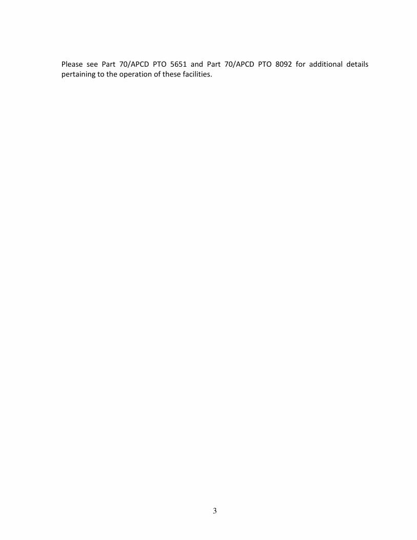
Figures 3-5 and 3-6 identify the point, area, and volume emission sources associated with
the POPCO facility. The emission sources have been identified by the new device
numbering sequence previously discussed in Section 3.1.

17
Table 3-5 AB2588 Substances to by Quantified for Year 2013 Toxics Emission Inventory - POPCO
Device Name APCD
ID
Device
ID
Ace
tald
eh
yd
e
Acr
ole
in
Am
mo
nia
1,3
-bu
tad
ien
e
Be
nze
ne
Ca
rbo
ny
l S
ulf
ide
Ch
lori
ne
Ch
loro
be
nze
ne
Cy
clo
he
xa
ne
Die
sel
Pa
rtic
ula
te
Die
thy
len
e G
lyco
l
Mo
no
bu
tyl
Eth
er
Eth
ylb
en
zen
e
Eth
yle
ne
Gly
cols
(D
EG
, E
G,
TE
G)
Fo
rma
lde
hy
de
He
xa
ne
Hy
rdra
zin
e
Hy
dro
chlo
ric
Aci
d
Hy
dro
ge
n S
ulf
ide
Me
tha
no
l
Na
ph
tha
len
e
PA
Hs
Ph
osp
ho
ric
Aci
d
Pro
py
len
e
Pro
py
len
e O
xid
e
So
diu
m H
yd
rox
ide
Tri
me
thy
lbe
nze
ne
(1
,2,4
)
To
lue
ne
Xy
len
es
Me
tals
OEHHA RA Health
Value?
���� ���� ���� ���� ����
N
o ���� ����
N
o ����
N
o ����
N
o ���� ���� ���� ���� ���� ���� ���� ���� ���� ���� ���� ����
N
o ���� ���� ����
Aerator A (Oxidizer Tank
No. 1) 105191 250120 x x x x
Aerator B (Oxidizer Tank
No. 2) 105192 250130 x x x x
Boiler A - Natural Gas 2350 150021 x x x x x x x x x x
Boiler A - Stretford
Tailgas 105204 150022 x x x x x x x x x x
Boiler B - Natural Gas 2351 150031 x x x x x x x x x x
Boiler B - Stretford
Tailgas 105204 150032 x x x x x x x x x x
Diesel Tanks 250200 x x
Emergency Air Generator 2357 150090 x x x x x x x x x x x x x x x x x x
Emergency Generator (G-
800) 2358 150060
x x x x x x x x x x x x x x x x x x
Evaporative Cooler 105199 150100 x x
Firewater Pump (805) 2359 150070 x x x x x x x x x x x x x x x x x x
Firewater Pump (806) 2356 150080 x x x x x x x x x x x x x x x x x x
GPU TEG Glycol Reboiler 2353 150050 x x x x x x x x x x x x
Methanol Tank 102620 150210
x
POPCO Compressor Seals
- Plant Wide 7079 380522 x x x x x x x x x x x
POPCO Fugitive
Components (Gas) - Plant
Wide
113979 360511 x x x x x x x x x x x x
POPCO Fugitive
Components (Oil) - Plant 7068 360512 x x x x x x x x x x x x

18
Device Name APCD
ID
Device
ID
Ace
tald
eh
yd
e
Acr
ole
in
Am
mo
nia
1,3
-bu
tad
ien
e
Be
nze
ne
Ca
rbo
ny
l S
ulf
ide
Ch
lori
ne
Ch
loro
be
nze
ne
Cy
clo
he
xa
ne
Die
sel
Pa
rtic
ula
te
Die
thy
len
e G
lyco
l
Mo
no
bu
tyl
Eth
er
Eth
ylb
en
zen
e
Eth
yle
ne
Gly
cols
(D
EG
, E
G,
TE
G)
Fo
rma
lde
hy
de
He
xa
ne
Hy
rdra
zin
e
Hy
dro
chlo
ric
Aci
d
Hy
dro
ge
n S
ulf
ide
Me
tha
no
l
Na
ph
tha
len
e
PA
Hs
Ph
osp
ho
ric
Aci
d
Pro
py
len
e
Pro
py
len
e O
xid
e
So
diu
m H
yd
rox
ide
Tri
me
thy
lbe
nze
ne
(1
,2,4
)
To
lue
ne
Xy
len
es
Me
tals
OEHHA RA Health
Value?
���� ���� ���� ���� ����
N
o ���� ����
N
o ����
N
o ����
N
o ���� ���� ���� ���� ���� ���� ���� ���� ���� ���� ���� ����
N
o ���� ���� ����
Wide
POPCO Maint. Abrasive
Blasting - Plant Wide 8796 370511 x
POPCO Maint. Painting &
Coating - Plant Wide 370512 x
POPCO Process Solvent
Loss - Plant Wide 105156 390520 x x
POPCO Pump Seals -
Plant Wide
7080/7
081 380521 x x x x x x x x x x x
Sulfinol TEG Reboiler 2352 150040 x x x x x x x x x x x x
Sulfur Loading 105182 150160 x
Thermal Oxidizer --
Planned Continuous
Flaring
107202
,
102615
150012 x x x x x x x x x x x
Thermal Oxidizer --
Planned Other ( SU,
Maintenance, Tailgas
Incineration)
102616 150013 x x x x x x x x x x x
Thermal Oxidizer -- Purge
& Pilot 102614 150011 x x x x x x x x x x x
Thermal Oxidizer --
Unplanned Other
(Miscellaneous, SRU
Failure)
108095 150014 x x x x x x x x x x x
Waste Liquid Storage
Tank (601) 103103 150270
x x
Water Treating Regulator 350140 x

19

20

21
4 Emission Estimation Techniques and Proposals
This section provides information on how emission rates will be estimated in the ATEIR for
both Las Flores Canyon and POPCO. Emission Estimation Techniques (EETs) are presented
in the following sections on a device category basis. Emissions are determined through one
of three basic means: permitted emission limits calculations, mass balance, or source test
data.
4.1 Las Flores Canyon Facility
4.1.1 Gas Turbine
Emissions from the Cogeneration Power Plant (CPP) come from the gas turbine generator
and the low-NOx duct burner associated with the Heat Recovery Steam Generator (HRSG).
NOx emissions from the gas turbine and duct burner are controlled by an ammonia injection
selective catalytic reduction (SCR) unit. Emissions are determined for the CPP under three
operating modes, as permitted in Part 70/APCD PTO 5651. The CPP is periodically required
to be shutdown/started up during unplanned events. These unplanned startup/shutdown
events are infrequent and unpredictable, so have not been included in this plan.
Table 4-1 CPP Operating Modes
Mode Equipment Load Heat Input
(MMBtu/hr)
APCD
Device
No.
Device ID Stack ID
Normal
Operations Gas Turbine 99% 460 6585 126021 26020
HRSG 41% 141 7865 126021 26020
Turbine Bypass 1% Gas
Turbine 4.60 7864 125010 25010
HRSG Only HRSG 100% 345 7865 126022 26020
Planned
SU/SD
Gas
Turbine/HRSG 308.821 7866 125010 25010
Air toxic emissions are estimated from the gas turbine, turbine bypass and HRSG using
emission factors from Table 3.1-3 of US EPA AP-42, as recommended by Ventura County
APCD (VC APCD, 2001) for natural gas fired turbines. Hexane and propylene emissions for
the gas turbine are calculated using the emission factors defined by the California Air Toxic
Emission Factor (CATEF) website as identified in Table E-1. Emissions from the turbine
bypass stack during Normal Operations are based on a leakage rate of one percent of the
gas turbine exhaust. Emissions from the HRSG/SCR unit associated with the injection of
ammonia (Device ID 2105) are estimated by multiplying the outlet concentration of
ammonia (slip) times the stack flowrate, as monitored by the continuous emission
monitoring system (CEM) as described further below. Hourly air toxic emissions are
estimated using the rated heat input for each equipment item as found in Part 70/APCD
PTO 5651.

22
Equation 4-1 Annual Average Emissions of NH3
( )( )1
323
6
3
10
C
CCMQCNHE
NHavg
yr
∗∗∗∗∗=
−
Where:
Eyr,NH3 = Average emission rate of ammonia, [lb/year]
Cavg = Average stack ammonia concentration, [ppm]
Q = Stack flowrate, [dscfm]
MNH3 = Molecular weight of ammonia, [17 lb/lb-mole]
C1 = Standard molar volume at 68 °F, [385 ft3/lb-mole]
C2 = 60 minute/hour
C3 = Hours of operation per year, [8,760 hours/year]
Equation 4-2 Hourly Maximum Emissions of NH3
( )( )1
23
6
max
3
10
C
CMQCNHE NH
hr
∗∗∗∗=
−
Where:
Ehr,NH3 = Maximum emission rate of ammonia, [lb/hour]
Cmax = Maximum hourly recorded stack ammonia concentration, [ppm]
4.1.2 Thermal Oxidizer and Waste Gas Incinerator
This category includes the thermal oxidizer in the Oil Treating Plant (OTP) as well as the
waste gas incinerator in the Stripping Gas Treating Plant (SGTP). The waste gas incinerator
has not operated with the Merox vent in recent years so this mode of operation will not be
included in the model. Emissions associated with unplanned startup/shutdown activities of
the waste gas incinerator will also be omitted due to the infrequent and unpredictable
nature of these events. Air toxic emission factors were developed by applying the CARB
speciation profile number 719 (ICE – Reciprocating – Natural Gas) to the total organic
carbon (TOC) emission factor for flares from Chapter 13 of US EPA AP-42; as provided by
Ventura County APCD in their AB 2588 Combustion Emission Factors (VC APCD, 2001).
Table 4-2 Thermal Oxidizer and Waste Gas Incinerator Devices
Plant Area Device Name APCD
Device No. Device ID Stack ID
SGTP Waste Gas Incinerator (w/out Merox) 7868 146031 46030
SGTP WGI - Planned Startup/Shutdown/Maintenance 7869 146032 46030
OTP Thermal Oxidizer - Purge and Pilot 1088 116011 16010
OTP Thermal Oxidizer - Planned Continuous (AG, LP) 1088 116012 16010
OTP Thermal Oxidizer - Planned Other 1088 116013 16010
OTP Thermal Oxidizer - Unplanned Other 1088 116014 16010

23
Emissions from the thermal oxidizer are calculated based on the following operating
scenarios: Planned Continuous – Acid Gas, Planned Continuous – Low Pressure, Purge &
Pilot, Planned – Other, and Unplanned – Other. Annual emissions of each toxic compound
will be calculated using the actual annual fuel use data and waste gas reported for 2013 for
these operating scenarios. Hourly air toxic emissions are estimated using the rated heat
input for the waste gas incinerator and maximum hourly gas flow rate for the thermal
oxidizer as found in Part 70/APCD PTO 5651.
Equation 4-3 Hourly Maximum Emissions for Thermal Oxidizer ��,��� � ����, � ���
Equation 4-4 Hourly Maximum Emissions for Waste Gas Incinerator ��,��� � ����, �� ����� ���
Equation 4-5 Average Annual Emissions for Thermal Oxidizer and WGI ��,��� � � � ��� Where:
Ei,max, = Max emission rate of substance i, [lb/hour]
Ei,avg = Average emission rate of substance i, [lb/year]
V = Total annual Volume of gas combusted [MMscf/year]
V max,TO = Max hourly gas flow rate [MMscf/hour]
V max,WGI = Max hourly heat input rate [MMBtu/hr]
HHV –Higher Heating Value of fuel combusted in WGI [Btu/scf]
EFi = Emission factor of toxic pollutant, [lb/MMscf]
4.1.3 Internal Combustion Engines
There are three permitted diesel-fired internal combustion engine, two of which are
permitted to power firewater pumps, and one stang pump. Hourly air toxic emission
factors were based on source testing conducted by several different organizations, as
reported by Ventura County APCD (VC APCD, 2001). Annual air toxic emission factors are
based on Table 3.3-1 of AP-42 as permitted in Part 70/APCD PTO 5651.
Table 4-3 Internal Combustion Engines
Plant Area Device Name APCD
Device No. Device ID Stack ID
OTP Firewater Pump A 1085 113961 13961
OTP Firewater Pump B 1086 113962 13962
OTP Stang Pump 8122 119990 19990
Hourly and annual emissions of each toxic compound will be calculated using the rated heat
input of each engine and the actual annual fuel use data reported for 2013 respectively.
Equation 4-6 Hourly Maximum Emissions for ICE ��,��� � ����� � ������ � ��� ����� ��

24
Equation 4-7 Average Annual Emissions for ICE ��,��� � ����� � ������ � �� ��� ����� ��
Where:
Ei,max, = Max emission rate of substance i, [lb/hour]
Ei,avg = Average emission rate of substance i, [lb/year]
Bhp = Maximum rated brake horsepower
BSFC = Brake Specific Fuel Consumption, [BTU/bhp-hr]
OH = Operating Hours, [Hours/year]
EFi = Emission factor of toxic pollutant, [lb/kgal]
HHV = Higher Heating Value of fuel, [BTU/gal]
CF = Conversion Factor, [kgal/1000 gal]
4.1.4 Fixed Roof Storage Tanks
LFC has several fixed roof storage tanks operating at the facility: (2) two oil storage tanks,
(2) two rerun tanks, (3) three diesel tanks, and (2) two demulsifier tote tanks. Breathing
and working losses from the rerun, and diesel tanks are estimated using the equations
defined for fixed roof tanks in chapter 7 of US EPA AP-42. Emissions from the oil storage
tanks are based on PSV events reported in the semi-annual compliance verification report
(CVR).
Table 4-4 Fixed Roof Storage Tanks
Profile Process
Stream
Plant
Location Service Device Name APCD ID Device ID Stack ID
LFC-7 Crude
OTP Liq Rerun Tank A 6570 214011 14011
Rerun Tank B 6571 214012 14012
TT Liq Oil Storage Tank A 6566 234011 34011
Oil Storage Tank B 6567 234012 34012
CARB Diesel OTP Liq Diesel Fuel Tanks 113963 13963
OTP Liq Diesel Storage Tank 114160 14160
CARB Demulsifier OTP Liq Demulsifier Tote
Tanks 1 - 4 6583
114021 14021
114022 14022
114023 14023
114024 14024
Emissions from the rerun and oil storage tanks are controlled through connections to the
vapor recovery system. The demulsifier tote tanks are connected to carbon canisters. The
diesel tanks vent to atmosphere.
Air toxic emission factors for the rerun tanks and the oil storage tanks were based on
samples collected from several streams throughout the process to more accurately describe
the emission from various locations. Sampling was conducted in 2013 as part of the
ATEIP/R for LFC and POPCO. The stream profile for the crude process stream (LFC-7) was

25
sampled from LFC’s treated crude. Air toxic emission factors for the diesel and demulsifier
tote tanks are based on the CARB speciation manual, profile number 297 (Crude Oil
Evaporation) as currently identified in Part 70/APCD 5651 for tanks.
Hourly and annual emissions of each toxic compound will be calculated using the permitted
maximum daily throughput and the actual annual throughput to these tanks as reported for
2013. The Rerun tanks and Oil Storage tanks are connected to vapor recovery. Emissions
are assumed to be reduced by 95% on an hourly and daily basis, and up to 99.8% on an
annual average. Emissions are estimated based on USEPA AP-42, Chapter 7 equations
consistent with the Part 70/APCD PTO 5651.
4.1.5 Wastewater Storage Devices
The produced water treatment system is located in the OTP; and treats the produced water
removed from the oil/water emulsion as well as the miscellaneous process waste water
streams. The produced water treatment system include both closed (vented to VR or SRU)
and open (fugitive) process devices. The closed portions of the system include an
equalization tank, two anaerobic filters, and the vacuum flash tower feed drum. The open
portions of the system are in the OTP and include aeration tanks, clarifiers, a skim tank, the
outfall batch tank, the waste sludge cake transfer unit, and the centrate sump.
Table 4-5 Produced Water Device Stream Grouping
Profile Process
Stream
Plant
Location Service Device Name
APCD
ID
Device
ID Stack ID
LFC-5 Anaerobic OTP Liq
Anaerobic Filter A 211090 11090
Anaerobic Filter B 211190 11190
Equalization Tank 6573 114240 14240
LFC-6 Aeration OTP Liq
Aeration Tank A 214250 14250
Aeration Tank B 214260 14260
Clarifier A 214280 14280
Clarifier B 214290 14290
Skim Tank 214500 14500
Outfall Batch Tank 214310 14310
Centrate Sump 114430 14430
Waste Sludge Cake Transfer
– A 113601 13601
Waste Sludge Cake Transfer
– B 113602 13602
Waste Sludge Cake Transfer -
C 113603 13603
LFC-1 Emulsion OTP Liq Vacuum Flash Tower Feed
Drum 211380 11380
Air toxic emission factors for these devices are determined using Henry’s Law and Raoult’s
Law. These emission factors are derived from assumed partial pressures associated with
the known constituents in the wastewater and Henry’s Law constants defined for the
individual air toxic pollutants. The air toxics in the produced water were determined

26
through process stream sample data collected in 2013 specified in Table 4-5 and provided in
Appendix A. The stream profiles used for the anaerobic, aeration, and emulsion process
streams were sampled at LFC.
Equation 4-8 Henry’s Law for Produced Water Treatment System ��,� � �� � �
!�," � ��,��",�
Where:
Xi = Mole fraction of substance i in water, [lb-mole/lb-mole]
Hi = Henry’s Law constant at temperature t, [atm/lb-mole/lb-mole]
Mi,w = Mass ratio for evaporation [lb substance i/lb water]
pi,t = Partial pressure of substance i at temperature t, [mm Hg]
pw,t = Partial pressure of water at temperature t, [mm Hg]
Equation 4-9 Raoult’s Law for Produced Water Treatment System
!�," � #$ � ��,��",�
Where:
Mi,w = Mass ratio for evaporation [lb substance i/lb water]
C1 = Concentration of substance in water, [fraction]
pi,t = Vapor pressure of substance i at temperature t, [mm Hg]
pw,t = Vapor pressure of water at temperature t, [mm Hg]
Hourly and annual emissions of each toxic compound will be calculated using the permitted
surface area of each device, the amount of water processed in a given hour, and the stream
speciation data consistent with the CARB/KVB Report (Emissions Characteristics of Crude Oil
Production in California, January 1983) used in Part 70/APCD PTO 5651.
Equation 4-10 Hourly Maximum Emissions from Produced Water Treatment System
%�,&'( � )' �! � * �!�," � +1 - #%100 /
Equation 4-11 Annual Average Emissions from Produced Water Treatment System
%�,'01 � )' �! � * �!�," � 2� � +1 - #%100 /
Where:
Ei,max = Max emission rate of substance i, [lb/hour]
Ei,avg = Average emission rate of substance i, [lb/year]
Na = Molar flux of water to air, [lb-mole/hr-ft2]

27
M = Molecular weight of water, 18 lb/lb-mole
A = Emitting surface area, [ft2]
Mi,w = Mass ratio for evaporation of Raoult’s Law, [lb substance i/lb water]
OH = Annual operating hours, [hours/year]
CE = Efficiency of emission control device connected to equipment
Equation 4-12 Diffusivity of Water to Air
345,� � 3.875 � 345 � ;< 273> ?$.@A � ;1 B> ?
Where:
DAB,t = Diffusivity of water to air at temperature t, ft2/hr
DAB = Diffusivity of water to air at 0°C, 0.220 cm2/sec
T = Temperature, °K
P = Barometric pressure, atm
Equation 4-13 Molar Flux of Water to Air
)4 � C345,� � B � ��'$ - �'D�EFG � H � I � �J&K
Where:
Na = Molar flux of water to air, [lb-mole/hr-ft2]
Pa1 = vapor pressure of water at temperature t, atm
Pa2 = 0
R = Gas Constant, 0.730 atm-ft3/lb mole-°R
z = Gas film thickness, ft
t = Temperature, °R
pbm =[ (P – pa2) – (P – pa1)]/ ln [(P – pa2)/ (P – pa1)]
4.1.6 Acids and Caustics Storage Devices
The devices at LFC containing various acids and caustics include the following:
Table 4-6 Acids and Caustics Storage Device Process Streams
Plant Area MSDS Device Name
APCD
Device
No.
Device
ID
Stack
ID
Various NA Chemical Storage Tote Tanks 7886 OOS OOS
SGTP Sodium Hydroxide, Various
Dilutions (20%) Fresh Caustic Day Tank 244120 44120
OTP Sodium Hydroxide, Various
Dilutions (20%) Caustic Tank 114380 14380
OTP Sodium Hydroxide, Various
Dilutions (20%) Waste Caustic Tank OOS OOS
OTP Sodium Hydroxide, Various
Dilutions (20%) Demineralizer Caustic Tank 114100 14100
OTP Ansulite 3% (DGME 10%) Foam Tank 134040 34040
OTP Hydrochloric Acid, 33-38% HCL Tanks 114360 14360

28
Plant Area MSDS Device Name
APCD
Device
No.
Device
ID
Stack
ID
OTP Phosphoric Acid, 70-85% Phosphoric Acid Tank 114370 14370
TT Ansulite 3% (DGME 10%) Foam Tank 134040 34040
CPP Hydrochloric Acid, 33-38% Acid Skid 125060 25060
CPP Sodium Hydroxide, 4% (1N) Cooling Water System 224060 24060
CPP Sodium Hydroxide, Various
Dilutions (20%) Caustic Skid 225050 25050
The Raoult’s Law and vapor diffusion method of estimating emissions of dilute acids and
caustics in water solution from liquid surfaces to air provides a conservative emission
estimate technique for these substances. See Appendix C for the table of default values
used to calculate emissions came from the CRC Handbook of Chemistry and Physics.
Equation 4-14 Raoult’s Law for Dilute Acids and Caustics
!�," � #$ � #D � ��,��",�
Where:
Mi,w = Mass ratio for evaporation [lb substance i/lb water]
C1 = Concentration of stock in water, [fraction]
C2 = Concentration of substance in stock (per MSDS), [fraction]
pi,t = Vapor pressure of substance i at temperature t, [mm Hg]
pw,t = Vapor pressure of water at temperature t, [mm Hg]
Air toxic emissions are calculated in a similar manner as the wastewater storage devices
described in the previous section) using the concentration of the caustic or acid, along with
the vapor pressure of water and the caustic/acid at the given temperature for the device.
Speciation data is based on the MSDS sheets for the solutions maintained in each of these
tanks.
Hourly and annual emissions of each toxic compound will be calculated using the permitted
surface area of each device and the amount of caustic in water solution processed in a given
hour (See Equation 4-10, Equation 4-11, Equation 4-12, and Equation 4-13). Emissions from
the Chemical Storage Tote Tanks or the Caustic Tank will not be included because the tanks
did not operate during the reporting period.
4.1.7 Steam System
All steam condensate used throughout the plant is returned to the CPP condensate handling
system. This system condenses steam to assist in power generation. The system also heats
the condensate and make-up water, and reduces the oxygen content of the stream to the
requirements of the HRSG. Hydrazine is a reducing agent used in the boiler feedwater to
scavenge oxygen. Since its boiling point is only slightly higher than water, it is assumed to
be present in the process stream, and all but the blow down fraction is emitted fugitively.

29
Table 4-7 Steam System Equipment
Plant
Area MSDS Device Name
APCD Device
No. Device ID Stack ID
CPP TRASAR (Hydrazine
0.01%)
Steam Condensate
System 221090 21090
CPP TRASAR (Hydrazine
0.01%) Steam Drum 221120 21120
CPP TRASAR (Hydrazine
0.01%) Deaerator 121110 21110
CPP TRASAR (Hydrazine
0.01%)
Steam System Chemical
Injection System 225020 25020
The hydrazine emission rate for the Steam Condensate System (2109) and the Steam Drum
(2112) is calculated using the following material balance equation:
Equation 4-15 Hourly Maximum Emissions from Steam System
%LMN,LO � %LMN,PO8760
Equation 4-16 Annual Average Emissions from Steam System
%LMN,PO � RLMN � 3LMN � #LMN � S1 - T U>100 V
Where:
Ehdz,yr = Average emission rate of hydrazine, lb/yr
Qhdz = Quantity of hydrazine dispensed, gal/yr (0.01% of Trasar dispensed)
Dhdz = Density of hydrazine solution, 8.7 lb/gal
Chdz = Concentration of hydrazine solution, weight percent
B/F = Ratio of blowdown to total feedwater makeup
The deaerator (121110) is used to remove dissolved oxygen, carbon dioxide and other gases
present in the demineralized makeup water and hot steam condensate through mechanical
separation. Oxygen removal is enhanced through the use of the oxygen scavenger
(hydrazine) added to chemically reduce the dissolved oxygen concentration. Hydrazine is
stored in the steam chemical injection system (225020). Emissions for these two devices
are estimated using the methods for acids and caustics, discussed in the previous section.

30
4.1.8 Sumps and Separators
The sumps and separators operating at LFC include the following:
Table 4-8 Sumps and Separators Process Stream Grouping
Profile Process
Stream
Plant
Location Service Device Name
APCD
ID
Device
ID
Stack
ID
POP-8 Sump SGTP Liq
Area Drain Oil/Water
Separator 6578 144060 44060
Area Drain Sump 6582 244050 44050
Open Drain Sump 6579 144070 44070
LFC-1 Emulsion OTP Liq Backwash Collection Tank 7885 214210 14210
MSDS NaOH (20%) OTP Liq Backwash Sump 6575 114420 14420
LFC-7 Crude
OTP Liq
Area Drain Sump 6581 214140 14140
Open Drain Sump 6576 114130 14130
Area Drain Oil/Water
Separator 6577 114150 14150
TT Liq
Area Drain Oil/Water
Separator 6572 134020 34020
Area Drain Sump 6580 234030 34030
NA NA CPP Chemical Sump NA NA
CARB 297 Crude Oil
Evaporation OTP Oily Sludge Thickener 6574 114230 14230
Emissions from these devices are estimated using CARB/KVB method which is dependent
upon the surface area of the sump or separator, the type of material being processed
through the device (heavy crude), as well as the service (1°, 2°, or 3°). Note that all sumps
and separators identified in Table 4-7 are assumed to be in tertiary, heavy oil service (3°).
Air toxic emission factors for these devices were based on samples collected from several
streams throughout the process to more accurately describe the emission from various
locations as identified in Table 4-7. Sampling was conducted in 2013 as part of the 2014
ATEIR for LFC and POPCO. The profile used for the sump process stream was sampled at
POPCO. The profiles for the emulsion, and crude process streams were specifically sampled
at LFC. The results of this sampling are found in Appendix A.
The chemical sump is a part of the Demineralized Water System and was identified in the
previous ATEIP/ATEIR, as being a non-emitting piece of equipment. The activities
associated with this device and system remains unchanged; therefore this device will not be
included in this emissions evaluation. The oily sludge thickener was not previously
modeled, so emissions have been calculated using the CARB speciation manual, profile
number 297 (Crude Oil Evaporation), as defined in Part 70/APCD PTO 5651. The backwash
sump now receives the waste caustic material which was previously diverted to the waste

31
caustic tank (14551). As a result, the emissions associated with the backwash sump will
include a 20% sodium hydroxide solution.
Hourly and annual emissions of each toxic compound will be calculated using the permitted
surface area of each device.
Equation 4-17 CARB/KVB Equation for Sumps and Separators
%�.'01 � +%U � W*24 / � �1 - #%� � 2� �YH�
%�,&'( � +%U � W*24 / � �1 - #%� �YH� Where:
Ei,avg = Average emission rate of substance i, [lb/year]
Ei,max = Max emission rate of substance i, [lb/hour]
EF = ROC emission factor, [lb/ft2-day]
SA = Unit surface area, [ft2]
CE = Control Efficiency
OH = Annual operating hours, [hours/year]
Wti = Weight fraction of toxic species i, [fraction]
4.1.9 Compressor Vent
LFC operates three SOV compressors and two vapor recovery (VR) compressors in the OTP,
each equipped with dual sealing systems which are connected to vapor recovery via the
distance piece of each compressor. The emissions from the back end of each distance piece
are routed through a common vent system, and directed to a carbon canister system. TOC
emissions will be calculated using the ROC emission factor defined in Part 70/APCD PTO
5651 which was established based on past source test data collected at the outlet of the
vents and applying the ROC/TOC factor from the CARB Speciation Manual, #757, to convert
to TOC.
Table 4-9 Compressor Vents
Profile Plant Area Device Name
APCD
Device
No.
Device ID Stack ID
CARB 757 OTP SOV Distance Piece Vent – Compressor A 7881 113011 13010
CARB 757 OTP SOV Distance Piece Vent – Compressor B 7881 113012 13010
CARB 757 OTP SOV Distance Piece Vent – Compressor C 7881 113013 13010
CARB 757 OTP VRU Distance Piece Vent – Compressor A 7882 113020 13020
CARB 757 OTP VRU Distance Piece Vent – Compressor B 7882 113030 13020
Profile Number 757 from the CARB Speciation Manual was used to determine air toxic
emissions from each compressor vent as specified in the current Part 70/APCD PTO 5651.
1 The Waste Caustic Tank has been out of service for several years, and currently remains out of service. As
such, it will not be included in the model.

32
Equation 4-18 Max Hourly and Annual Average Emissions from Compressor Vents
%�.'01 � �%U� � +<2#G2#/ � 2� �YH�
%�,&'( � �%U� � +<2#G2#/ �YH�
Where:
Ei,avg = Average emission rate of substance i, [lb/year]
Ei,max = Max emission rate of substance i, [lb/hour]
EF = ROC emission factor, [lb/hr]
TOC/ROC = CARB Speciation Profile #757 conversion to TOC
OH = Annual operating hours, [hours/year]
Wti = Weight fraction of toxic species i, [fraction]
4.1.10 Pigging Equipment
LFC operates one oil emulsion pig receiver at the Transportation Terminal. TOC emissions
will be calculated using the ROC emission factor and applying the ROC/TOC fraction defined
in Part 70/APCD PTO 5651, and 2013 pigging event data.
Table 4-10 Pigging Equipment
Profile Plant Area Device Name APCD Device No. Device ID Stack ID
CARB 757 TT Oil Emulsion Pig Receiver 6565 137100 37100
Equation 4-19 Density of Vapor at Actual Conditions
Z � B �!YG � < � �14.7 [ 1� � 19.310.73 � 560 � 0.0504 ] ^_`Hab
Where:
ρ = Density of vapor remaining in vessel, lb ROC/ft3
P = Remaining vessel pressure, psig
MW = 19.3 lb/lb-mol
T = Temperature in Rankine, 100°F
R = 10.73 ft3/psi*R*lb-mol

33
Equation 4-20 TOC Emission Factor
[ ]
[ ]eventTOClbEF
ft
lbftEF
VEF
/956.3
0504.05.783
3
−=
∗=
∗= ρ
Where:
EF = lb TOC/pigging event
V = Volume of vessel, ft3
ρ = Density of vapor remaining in vessel, lb ROC/ft3
Air toxic emissions were determined using the TOC emission factor calculated from
equations
Equation 4-19and
Equation 4-20 above.
Equation 4-19 is described in section 4 of Part 70/APCD PTO 5651 for pigging events. The
pig receiver is purged with sweet fuel gas prior to opening, as such the emitting stream
consists primarily of gas vapors. CARB speciation profile #757 – Oil & Gas Production
Fugitives – Gas Service, is used to calculate the air toxic emissions as described in the
current permit.
4.1.11 Fugitive Components
LFC maintains fugitive components consisting of valves, connections, compressor seals, and
pump seals in both gas and oil service. These components have been grouped according to
the location of the facility they are found (Stripping Gas Treating Plant, Oil Treating Plant,
Cogeneration Power Plant, and Transportation Terminal), the service code identified for the
components, and whether they are in gas or oil service. Each P&ID was reviewed to identify
an appropriate stream profile for each gas and liquid service components prior to grouping
the components by plant area. The stream profiles were chosen based on the type of
equipment and the processes occurring (service code) within the P&ID.
There are no “Device ID’s” to reference, as the previous ATEIP/ATEIR relied on “systems”
created for the purpose of modeling. The past plan summed the fugitive emissions for all
components in each plant area and assigned that total to each of several systems defined
within the plant area. By assigning the total plant area fugitive emissions to each system,
instead of determining the number of components actually associated with each system,
the air toxic emissions were greatly over estimated. If data were available on fugitive
components by device, it is still not clear from the past plan what devices were actually

34
associated with the systems, therefore determining the number of components that should
be assigned to these systems is not possible.
Data is available, as required in the Part 70 Compliance Verification Reports (CVRs), on the
number and type of components in each plant area. The inventory also maintains a record
of the “service code” and P&ID for each component, which further describes a more specific
process associated with the component. This plan focuses on the effect of the various
component types and numbers by service code and P&ID in each plant area of the facility.
TOC emissions have been calculated using the component leakpath (clp) emission factors
defined in Part 70/APCD PTO 5651. Air toxic emissions are calculated using the stream data
collected in 2013. The most appropriate gas and liquid stream for each P&ID and service
code were chosen based on the type of equipment and processes occurring in the P&ID.
The tables which group the fugitive components by P&ID are fairly extensive, and have been
included in Appendix H. Note that the total component count reported for the facility under
AB2588 differs from the count identified by the APCD as subject to permitting and control
under district Rule 331. AB2588 includes process streams that would be considered exempt
under district Rule 331. Data for each stream profile identified in these tables is provided in
Appendix A.
4.1.12 Maintenance - Welding
LFC and POPCO conduct welding operations on an as needed basis to insure equipment is
maintained in good working order without cracks or stress points that might cause the
equipment to fail. As part of this plan update ExxonMobil has identified the specific type of
welding operations that occur, noted in the table below.
Table 4-11 Welding Operations
Profile Plant Area Device Name APCD Device No. Device ID Stack ID
EPA OTP - Shop Shielded Metal Arc (SMAW) NA 318021 18020
EPA OTP - Shop Gas Metal Arc (GMAW) NA 318022 18020
The equations for estimating emissions from Shielded Metal Arc Welding (SMAW) and Gas
Metal Arc Welding (GMAW) come from San Diego County APCD and EPA. For trace metals
without an AP-42 listed emissions factor (AP-42 Section 12.19), the factors identified by San
Diego APCD were used.
Equation 4-21 Max Hourly and Annual Average Emissions from Welding – with AP-42 Factor %' � �%U� � c' � �1 - d� %L � �%U� � cL � �1 - d�

35
Equation 4-22 Max Hourly and Annual Average Emissions from Welding – without AP-42 Factor
%' � �%U� � c' � +UefdhdidjkHdjkHd^_l`efd^_jmn / � �)*WW#2Uefd#mjjdoHpmiUkoHmj�� #�
%L � �%U� � cL � +UefdhdidjkHdjkHd^_l`efd^_jmn / � �)*WW#2Uefd#mjjdoHpmiUkoHmj�� #�
Where:
Ea = Annual emissions of each listed toxic air contaminant per device, (lbs/year)
Eh = Maximum hourly emissions of each listed toxic air contaminant per device, (lbs/hour)
Ua = Annual usage of each welding rod, (lbs/year)
Uh = Maximum hourly usage of each welding rod, (lbs/hour)
EF = Listed substance emission factor from AP-42, (lbs listed substance/lb rod consumed)
e = Control equipment PM10 collection and removal efficiency
4.1.13 Maintenance – Abrasive Blasting
LFC and POPCO conduct abrasive blasting using CARB-certified sands in preparation for
surface coating the equipment. This process emit particulates coming from the base
material to be blasted, from the prior surface coating being removed, as well as from the
abrasive blasting material. Actual air contaminants released depend on the specific
abrasive blasting activity, but will include metals and silica.
Table 4-12 Abrasive Blasting
Plant Area Device Name APCD Device No. Device ID Stack ID
CPP Abrasive Blasting NA 370211 60211-3
OTP Abrasive Blasting NA 370111 60111-8
SGTP Abrasive Blasting NA 370411 60411-3
TT Abrasive Blasting NA 370311 60311-4
The equations for estimating emissions from abrasive blasting come from Bay Area AQMD
Permit Handbook and EPA AP-42 Ch. 13.2.6. The California Air Toxics Emission Factors
(CATEF) database was queried to identify emission factors for common particulate metals
emitted during abrasive blasting operations.
Equation 4-23 Max Hourly and Annual Average Emissions from Abrasive Blasting %' � �%U� � c' � ;1 - * 100> ?
%L � �%U� � cL � ;1 - * 100> ?
Where:
Ea = Annual emissions of particulate metal, (lbs/year)

36
Eh = Maximum hourly emissions of particulate metal, (lbs/hour)
Ua = Annual usage of blasting material (lbs/year)
Uh = Maximum hourly usage of blasting material, (lbs/hour)
EF = Listed substance emission factor, (lb listed substance/1000 lb Abrasive)
A = Abatement Efficiency (%)
4.1.14 Solvent Use
LFC and POPCO use solvents for a variety of purposes throughout each facility. Solvents are
used for parts cleaning/degreasing, surface wiping cleaning, lab analysis, and paint thinning.
Solvent use is conducted in the maintenance shop, the QC lab, and at the actual location of
the equipment being maintained.
Table 4-13 Solvent Use Sources
Plant Area Device Name APCD Device No. Device ID Stack ID
Maintenance Shop Parts Cleaning 318023 18020
CPP Painting & Coating 370212 60211-3
OTP Painting & Coating 370112 60111-8
SGTP Painting & Coating 370412 60411-3
TT Painting & Coating 370312 60311-4
QC Lab Lab Analysis 111990 11990
Emissions are estimated based on the type of solvent used, the VOC content and density of
the solvent, solvent recovery method, and amount used each year, consistent with existing
reporting requirements under Part 70/APCD PTO 5651. The following emission calculation
methods are used depending type of solvent use as approved under LFC’s Solvent
Reclamation Plan:
Type of Solvent Use Recovery Method Control
Efficiency
Calculation
Method
Parts Cleaning w/Exempt Cleaners and
Equipment
Open Drain 75% A
Closed Container 90% A
Parts Cleaners/Degreasers w/Remote
Solvent Reservoir
Open Drain 75% A
Closed Container 90% A
Wipe Cleaning Open Drain or Closed
Container 0% B
Lab Analysis Open Drain 75% C
Closed Container 90% C
Spray Painting Closed Container 90% D
Brush Painting Closed Container 90% D
Equation 4-24 Emission Calculation Method for Parts Cleaning – Method A

37
%4 � CFqrM - �rO � 0.97�s [ qrO � 0.97 � �1 - G%�sK � r2##miHdiHE
Equation 4-25 Emission Calculation Method for Wipe Cleaning – Method B %5 � rM � r2##miHdiH
Equation 4-26 Emission Calculation Method for Lab Analysis – Method C %t � FqrM � �1 - 0.95�s [ q�rM � 0.95� � �1 - G%�sK � r2##miHdiH
Equation 4-27 Emission Calculation Method for Painting – Method D %u � FqrM - rOs [ qrO � �1 - G%�sK � r2##miHdiH
Where:
Vd = Volume of solvent dispensed
Vr = Volume of solvent recovered
RE = Recovery Efficiency

38
4.2 POPCO Gas Plant
4.2.1 External Combustion Equipment
The external combustion equipment at POPCO includes two utility boilers (B-801 A and B-
801 B), the sulfinol TEG reboiler, the GPU TEG glycol reboiler, and the forced air furnace. Air
toxic emissions for these units are estimated using emission factors developed by source
tests completed by the California Air Resources Board (CARB), as reported by the Ventura
County APCD (VC APCD, 2001).
The utility boilers combust plant fuel gas as well as Stretford tailgas resulting from the three
stage sulfur recovery unit. The VC APCD natural gas based emission factors have been
modified from natural gas factors assuming the tailgas has an average higher heating value
of 25 Btu/scf as specified in the current Part 70/APCD PTO 8092.
The forced air furnace is currently out of service, as such it will not be included in the
model.
Table 4-14 External Combustion Equipment
Device Name APCD Device No. Device ID Stack ID
Boiler A – Plant Fuel Gas 2350 150021 50020
Boiler A – Tailgas Incineration 150022 50020
Boiler B – Plant Fuel Gas 2351 150031 50030
Boiler B – Tailgas Incineration 150032 50030
Forced Air Furnace 8792 OOS OOS
GPU TEG Glycol Reboiler 2353 150050 50050
Sulfinol TEG Reboiler 2352 150040 50040
Hourly and annual emissions of each toxic compound will be calculated using the rated heat
input of each device and the actual annual fuel use data reported for 2013, respectively.
Hourly air toxic emissions associated with the Sulfur Recovery Unit Stretford tailgas
incineration in the boilers are calculated assuming there is approximately 5.62 MMBtu/hr
additional heat released to the boilers from the Stretford tailgas. Annual air toxic emissions
associated with the SRU are calculated using the actual annual tailgas fuel use data reported
for 2013.
Equation 4-28 Maximum Hourly Emissions from External Combustion Equipment %�,&'( � !UG � ��r � #U$ � #UD � %U�
Equation 4-29 Average Annual Emissions from External Combustion Equipment %�,'01 � *U � %U�

39
Where:
Ei,avg = Average emission rate of substance i, [lb/year]
Ei,max = Max emission rate of substance i, [lb/hour]
MFR = Maximum firing rate, [MMBtu/hr]
AF = Annual Fuel Use, [MMscf/year]
HHV = Higher Heating Value, [Btu/scf]
CF1 = Conversion Factor, 106 Btu/MMBtu
CF2 = Conversion Factor, 106 scf/MMscf
EFi = Toxic emission factor, [lb/MMscf]
4.2.2 Sulfur Loading
Device Name APCD Device No. Operator ID Device ID Stack ID
Sulfur Loading 105182 P-A403 A/B 150160 50160
Sulfur Pit 105178 SP-A401 NA NA
Acid gas from the amine unit is processed in three stages in the SRU. The third stage of the
unit takes the H2S enriched tailgas through a Stretford process where the H2S is absorbed in
a two-stage contactor system. Once the H2S has been absorbed, it is converted to
elemental sulfur, which is then skimmed from the Stretford solution and sent to a filter
press to remove residual Stretford solution prior to being shipped offsite via trucks.
The sulfur shipped offsite is maintained in the sulfur pit (SP-A401) prior to shipment.
Emissions from the pit are routed through a vent to the Evaporative Cooler where the H2S is
scrubbed with Stretford solution prior to release to the atmosphere (See Appendix B).
Emissions associated with the sulfur pit are accounted for at the Evaporative Cooler.
The air toxic emission factor for hydrogen sulfide during loading operations is based on
source testing completed in September 1990 during actual sulfur loading at the POPCO
truck loading station. The results of the source test estimated hydrogen sulfide emissions at
0.0015 lb/minute based on the following assumptions:
• Sulfur loading rate of ~1670 lb S/minute
• Air flow rate = 245 scfm
• Hydrogen Sulfide concentration = 69 ppmv
Annual emissions assume one truck is loaded per week, with each loading event taking ½
hour to complete; consistent with the assumptions made in the previous ATEIP.

40
4.2.3 Internal Combustion Engines
There are four permitted diesel-fired internal combustion engine, two of which are
permitted to power firewater pumps, one for emergency power, and one to generate
power for an emergency air compressor. The hourly air toxic emission factors were based
on source testing conducted by several different organizations, as reported by Ventura
County APCD (VC APCD, 2001). Annual air toxic emission factors are based on Table 3.3-1 of
AP-42 as permitted in Part 70/APCD PTO 8092.
Table 4-15 Internal Combustion Engines
Device Name APCD Device No. Device ID Stack ID
Emergency Air Generator 2357 150090 50090
Emergency Generator (G-800) 2358 150060 50060
Firewater Pump (805) 2359 150070 50070
Firewater Pump (806) 2356 150080 50080
Hourly and annual emissions of each toxic compound will be calculated using the rated heat
input and actual annual fuel use data reported for 2013, respectively.
Equation 4-30 Hourly Maximum Emissions for ICE ��,��� � ����� � ������ � ��� ����� ��
Equation 4-31 Average Annual Emissions for ICE ��,��� � ����� � ������ � �� ��� ����� ��
Where:
Ei,max, = Max emission rate of substance i, [lb/hour]
Ei,avg = Average emission rate of substance i, [lb/year]
Bhp = Maximum rated brake horsepower
BSFC = Brake Specific Fuel Consumption, [BTU/bhp-hr]
OH = Operating Hours, [Hours/year]
EFi = Emission factor of toxic pollutant, [lb/kgal]
HHV = Higher Heating Value of fuel, [BTU/gal]
CF = Conversion Factor, [kgal/1000 gal]
4.2.4 Thermal Oxidizer
This category includes the John Zink thermal oxidizer operated at the POPCO Gas Plant.
Table 4-17 lists all flaring categories permitted under Part 70/APCD PTO 8092 as well as
ATC/PTO 12020. The Unplanned Other – SRU Failure and Unplanned Other – Worst Case
Emergency categories have not been included in the air toxic emission calculations or
modeling since no actual emissions have occurred for the reporting year. Air toxic emission
factors were developed by applying the CARB speciation profiles to the total organic carbon
(TOC) emission factor for flares from US EPA AP-42; as provided by Ventura County APCD in
their AB 2588 Combustion Emission Factors (VC APCD, 2001).

41
Table 4-16 Thermal Oxidizer Equipment
Device Name APCD Device No. Device ID Stack ID
Purge and Pilot 102614 150011 50010
Planned Continuous Flaring 107202 150012 50010
Planned Other (SU, Maintenance, TG Incin) 102616 150013 50010
Unplanned Other (Miscellaneous, SRU Failure) 108095 150014 50010
Unplanned Other – Worst Case Emergency 102617 NA NA
Hourly and annual emissions of each toxic compound will be calculated using the rated heat
input for each flaring category and actual annual fuel use data reported for 2013,
respectively.
Equation 4-32 Maximum Hourly Emissions from Flaring %�,&'( � !UG � ��r � #U$ � #UD � %U�
Equation 4-33 Average Annual Emissions from Flaring %�,'01 � *U � %U�
Where:
Ei,avg = Average emission rate of substance i, [lb/year]
Ei,max = Max emission rate of substance i, [lb/hour]
MFR = Maximum firing rate, per flare category, [MMBtu/hr]
AF = Annual Fuel Use, [MMscf/year]
HHV = Higher Heating Value, [Btu/scf]
CF1 = Conversion Factor, 106 Btu/MMBtu
CF2 = Conversion Factor, 106 scf/MMscf
EFi = Toxic emission factor, [lb/MMscf]
4.2.5 Aerators and Evaporative Cooler
The aerators (referred to as the Stretford Oxidizer Tanks in Part 70/APCD PTO 8092) and
evaporative cooler are a part of the Sulfur Recovery Unit (SRU), and have the potential to
release emissions of sodium hydroxide, hydrogen sulfide, and dissolved metals as they
aerate and recirculate Stretford solution. Two aerators bubble air through the process
solution. The process solution is then pumped to the evaporative cooler where air flows
countercurrent to the solution, resulting in some fluid entrainment as drift droplets. The
majority of the emissions from the aeration and evaporative cooling processes occur from
the evaporative cooler.

42
Table 4-17 Aerators and Evaporative Cooler
Profile Process Stream Device Name APCD
Device No.
Device
ID
Stack
ID
POP-9 Stretford Absorber Outlet Aerator A (Oxidizer Tank No. 1) 105191 250120 50120
POP-9 Stretford Absorber Outlet Aerator B (Oxidizer Tank No. 2) 105192 250130 50130
POP-9 Stretford Absorber Outlet Evaporative Cooler 105199 150100 50100
Emissions of ROC from the aerators come from the results of the APCD approved source
test completed in June 2013 (See Appendix D) corrected for TOC using CARB Speciation
Profile #532 - Oil & Gas Extraction – Well heads, cellars, and oil & water separators. Air
toxic emissions for all three devices were determined using the CARB-sponsored cooling
tower emission estimation technique (ARB, 1988). This method uses the speciation data
obtained at POPCO from the outlet of the Stretford Absorber Columns (POP-9) collected as
part of the 2013 sampling series (Appendix A). This sample point represents the location in
which the Stretford solution is expected to be the most concentrated as it moves through
the aerators and evaporative cooler.
Equation 4-34 Maximum Hourly Emissions from Aerators and Evaporative Cooler %�,&'( � 3U �YG �YU� � Z � #U$
Equation 4-35 Average Annual Emissions from Aerators and Evaporative Cooler %�,'01 � 3U �YG �YU� � 2U � Z � #U$
Where:
Ei,avg = Average emission rate of substance i, [lb/year]
Ei,max = Max emission rate of substance i, [lb/hour]
DF = Drift Fraction, [0.0002 gpm/gpm]
WR = Water Circulation Rate, [330 gpm]
WFi = Weight Fraction of substance I in Stretford Solution, [ppmv i/106 H2O]
OF = Operation Fraction [Hours/yr/8760 hours/yr]
ρ = Density, [8.33 lb/gal]
CF1 = Conversion Factor, [60 min/hour]
4.2.6 Storage Tanks
POPCO has a few miscellaneous storage tanks permitted to operate at the facility: the
methanol tank and the two diesel tanks. Breathing and working losses from the diesel tanks
are estimated using the equations defined for fixed roof tanks in chapter 7 of US EPA AP-42.
Emissions from the methanol tank are based on the ideal gas law and vapor displacement
during tank fillings.
Air toxic emission factors for the diesel tanks are based on the CARB speciation manual,
profile number 297 (Crude Oil Evaporation) as currently permitted.

43
Table 4-18 Storage Tanks
Profile Process Stream Service Device Name APCD ID Device ID Stack ID
CARB 297 Diesel Liquid Diesel Tanks NA 250200 50200
MSDS Methanol Liquid Methanol Tank 102620 150210 50210
Hourly and annual emissions of each toxic compound will be calculated using the actual
annual throughput to these tanks as reported for 2013.
4.2.7 Wastewater Storage Tanks
POPCO operates two wastewater tanks. Emissions from these tanks are controlled by
carbon canisters. Tank T-807 is currently not in service, so emissions from this unit will not
be characterized in this ATEIP/ATEIR. The wastewater tanks at POPCO have not been
characterized in previous ATEIP/ATEIRs.
Table 4-19 Wastewater Storage Tanks
Profile Process Stream Service Device Name APCD Device
No.
Device
ID
Stack
ID
POP-8 Sour Water
Stripper Liquid Waste Liquid Storage Tank (601) 103103 150270 50270
NA NA Liquid Waste Liquid Storage Tank (807) 103104 OOS OOS
ROC emissions from the wastewater tank T-601 are based on the APCD approved source
test completed in January 2012 assuming 75% control for the carbon canisters (see
Appendix D). The ROC emissions were converted to TOC using the CARB Speciation Profile
#532 – Oil & Gas Extraction – Well heads, cellars, and oil & water separators. The air toxics
in the wastewater were determined from the sour water process stream (POP-8) collected
at the inlet to the sour water stripper at POPCO which receives water prior to being sent to
the wastewater tanks. This stream data was collected in 2013 as provided in Appendix A.
Air toxic emission factors for the operating wastewater tank are determined using Henry’s
Law and Raoult’s Law as described in Section 4.1.5 for the Wastewater storage tanks used
at LFC. These emission factors are derived from assumed partial pressures associated with
the known constituents in the wastewater and Henry’s Law constants defined for the
individual air toxic pollutants as described in Appendix C.
4.2.8 Maintenance - Welding
POPCO conducts welding operations on an as needed basis to insure equipment is
maintained in good working order without cracks or stress points that might cause the
equipment to fail. ExxonMobil uses the Shielded Metal Arc Welding (SMAW) process and

44
the Gas Metal Arc Welding (GMAW) processes. Note, welding operations for LFC and
POPCO are conducted at the maintenance shop at LFC, as such there is not a separate
emissions point for POPCO. See Section 4.1.11 for additional details
4.2.9 Fugitive Components
POPCO maintains fugitive components consisting of valves, connections, compressor seals,
and pump seals in gas and light liquid service. Each P&ID was reviewed to identify an
appropriate stream profile for the processes shown in the P&ID. Due to the smaller size of
POPCO relative to LFC the applicable streams for each P&ID are summarized plant-wide as
one volume source for the facility. See Appendix B for the location of the stream samples
used, and Appendix I for the component summary by stream profile.
TOC emissions have been calculated using the emission factors defined by component leak
path (clp) in Part 70/APCD PTO 8092. Air toxic emissions are calculated using the stream
data collected in 2013. The most appropriate gas and liquid stream for each P&ID and
service code were chosen based on the type of equipment and processes occurring in the
P&ID.

45
5 Source Modeling Parameters
The source release parameters for modeling are presented separately below for the
traditional LFC sources and the POPCO sources. The identification numbering scheme has
been modified from the past to avoid potential conflicts between sources for the two
facilities. The source IDs are still five digits, the maximum allowed within the HARP risk
assessment software. Except for plant-wide fugitive sources, the LFC source IDs are based
the ExxonMobil 4-digit equipment number. Therefore, the LFC IDs begin with "1", "2", "3",
or "4" for OTP, CPP, TT or SGTP, respectively. The fifth digit is a "0" unless the same
equipment number applies to more than one piece of equipment. For POPCO, source IDs
are a 5-digit number beginning with "5" followed by the past 3-digit source number, and
ending in "0".
There are two OTP stacks that do not have 4-digit equipment numbers. Because of this, and
to be consistent with the other LFC ID numbers, new stack ID numbers needed to be
assigned. Previously, the firewater pump fuel tanks had used the stack ID of 80000; this ID
has been changed to 13963 because of the fuel tanks' association with the OTP firewater
pumps (13961 and 13962). Also, the Stang pump had previously used the stack ID of 20000;
this has been changed to 19990.
The assignment of 5-digit ID numbers for plant-wide fugitive volume sources are discussed
within Sections 5.3 and 5.6 below.
5.1 Las Flores Canyon
Source modeling parameters for LFC are presented in Table 5-1 for point sources, Table 5-2
for area sources, and Table 5-3 for volume sources.
Source locations are UTM coordinates in the NAD27, Zone 10 reference and were
determined primarily from geo-coded aerial imagery. For area sources, the coordinates
represent the southwest corner of the area consistent with the requirements of the ISCST3
model embedded in the HARP risk assessment modeling system. Except for plant-wide
volume sources, the locations of the devices associated with these sources are shown in
Figures 3-1 through 3-4. Notably, for cases where the device is connected to a carbon
canister, the actual emission release point may be located a few meters from the device.
5.1.1 Point Sources
The release parameters (height, stack diameter, exit temperature, and exit velocity) for the
point sources were largely carried over from the previous AB 2588 analyses. Notable
exceptions to this are as follows. The exit temperature and exit velocity for the thermal
oxidizer were adjusted to be consistent with discussions with John Zink during the
ExxonMobil/POPCO Synergy Project; specifically, the temperature and velocity for the LFC
thermal oxidizer were increased slightly over values used in the past AB 2588 analyses.
John Zink was consulted relative to anticipated flow and temperature measurements. Flow

46
measurement data were based on anticipated air to fuel ratios for this natural draft device.
John Zink indicated that a reasonable air to fuel ratio would be between 20 and 40 to 1 on a
volumetric basis. ExxonMobil’s calculations used a 20 to 1 ratio average. Temperature data
were based on technical data provided by John Zink. For the AB-2588 ATEIP stack
parameter data, no actual temperature or flow measurements have been taken. The
temperature and exit velocities shown for the thermal oxidizer reflect continuous
operations. The short-term release parameters associated with the maximum hourly flaring
emissions will be determined based on the actual worst-case flaring event for 2013
operations. For non-buoyant point source releases (for example, tank vents), nominal stack
diameter and exit velocity values have been assigned, and they will be modeled using
ambient temperature to ensure that there is no appreciable plume rise from these sources.
Sumps listed in Table 5-1 are controlled with carbon canisters and are therefore treated as
non-buoyant point sources.
5.1.2 Area Sources
Area sources will be used to represent emissions from two dimensional sources for which it
is appropriate to assume a negligible vertical distribution. Many of the area sources are
tanks not connected to vapor recovery or carbon canisters, though this source type also
includes filters, aerators, and clarifiers.
5.1.3 Volume Sources
Volume sources include various plant-wide fugitive emissions categories grouped by plant
location (CPP, OTP, SGTP, and TT). These categories include:
• piping components (gas and oil),
• pump seals,
• compressor seals,
• process solvent losses,
• maintenance abrasive blasting, and
• maintenance painting & coating.
The “Fugitive Components” volume sources (i.e., piping components and equipment seals)
for each LFC plant and service code grouping will include emissions from devices not
otherwise represented in the inventory. The coverage for each service code grouping
specified in Section 4 is based on the plant location (CPP, SGTP, OTP, or TT) as it is not
feasible to define smaller geographic areas within each plant.
Previous AB2588 modeling for LFC associated fugitive component emissions with various
devices or “systems” within each plant. Generic ROC emission values were previously
assumed for each plant, and applied to multiple devices or systems within each plant. This

47
prior approach is inconsistent with the APCD’s preferred method of defining areas in which
the exact component count and associated emissions could be quantified. Therefore, the
device and stack identification numbers for “fugitive devices” as defined in the prior
ATEIP/ATEIR could not be used.
For the 2013 inventory, all volume sources representing plant-wide emissions have a 5-digit
Stack ID that begins with "60". This is followed by a single digit identifying the LFC plant as
follows:
1. OTP
2. CPP
3. TT
4. SGTP
There are potentially two sets of fugitive volume sources for each plant, as indicated by the
fourth digit:
1. Fugitive emissions that can occur throughout a relatively deep surface layer in each
plant. These emissions result from:
a. piping components
b. maintenance abrasive blasting
c. maintenance painting & coating
2. Fugitive emissions that occur in a relatively shallow surface layer. These emissions
result from:
a. pumps seals
b. compressor seals
c. process solvent losses (includes wipe cleaning activities)
The fifth (rightmost) digit identifies the three to eight volume sources used to approximate
the footprint of each plant. Using multiple volume sources for each plant allows a better
spatial distribution than is possible with a single, larger volume source. The fugitive volume
sources are depicted in Figure 5-1. For plotting purposes, the volume sources are depicted
as circles; the diameter of each circle within a group is equal to the center to center
distance between adjacent "in-line" volume sources. However, the value of the Sigma-
y(init) parameter input to the HARP model is this distance divided by 2.15, consistent with
Table 2.2.4 of the District's Modeling Guidelines for Health Risk Assessments.
As an example of this numbering system, a volume source for modeling fugitive emissions
from SGTP piping components, maintenance abrasive blasting, and/or maintenance
painting & coating would be in the range of 60411 through 60413 because SGTP is
represented by three volume sources.
The vertical extent of the fugitive volume sources for which the fourth digit is a "1" is
different for each plant; the specific values were determined based on visual inspection of
each plant. For volume sources with a "2" as the fourth digit, the vertical extent is set to a
fixed vertical dimension based on the values assigned to the volume source representing

48
pump seals in the past analyses for POPCO. Note that in past analyses for LFC, fugitive
emissions were represented by surface-based square area sources – one for each plant.
There is also a single volume source representing emissions from welding and parts cleaning
activities inside Building 1802 of OTP. These emissions exit the building through natural
building ventilation processes, so the volume source dimensions are based on the building
dimensions.

49
Table 5-1 Las Flores Canyon Point Sources
Plant Area Device Name
New
Stack
ID
UTM Coordinates Release
Height
Stack
Diameter
Exit
Temperature
Exit
Velocity
UTME UTMN (ft) (ft) (°F) (fpm)
OTP Quality Control Lab Vent 11990 771811.7 3819699.0 17.0 0.10 ambient 0.1
OTP SOV Distance Piece Vent2 13010 771687.9 3819635.4 4.0 0.10 ambient 0.1
OTP VRU Distance Piece Vent 2 13020 771823.9 3819499.8 4.0 0.10 ambient 0.1
OTP Sludge Hdlg Vent Exhaust 2 13050 771763.5 3819588.4 4.0 0.10 ambient 0.1
OTP Firewater Pump A 13961 771859.9 3819586.8 15.3 0.66 700.1 3562.0
OTP Firewater Pump B 13962 771865.9 3819586.8 15.3 0.66 700.1 3562.0
OTP Firewater Pump Diesel Fuel Tanks 13963 771862.9 3819584.4 16.3 0.10 ambient 0.1
OTP Demulsifier Tote Tank 1 14021 771700.6 3819545.4 12.5 0.10 ambient 0.1
OTP Demulsifier Tote Tank 2 14022 771702.3 3819545.4 12.5 0.10 ambient 0.1
OTP Demulsifier Tote Tank 3 14023 771704.0 3819545.4 12.5 0.10 ambient 0.1
OTP Demulsifier Tote Tank 4 14024 771705.7 3819545.4 12.5 0.10 ambient 0.1
OTP Demineralizer Caustic Tank 14100 771702.9 3819477.8 14.0 0.10 ambient 0.1
OTP Open Drain Sump2 14130 771810.5 3819542.0 4.0 0.10 ambient 0.1
OTP Area Drain Oil/Water Separator 2 14150 771865.4 3819566.6 4.5 0.10 ambient 0.1
OTP Diesel Storage Tank 14160 771713.2 3819541.4 16.0 0.10 ambient 0.1
OTP SOV Lube Oil Tank 14170 771672.3 3819617.3 15.0 0.10 ambient 0.1
OTP VR Lube Oil Tank 14190 771802.2 3819518.4 15.0 0.10 ambient 0.1
OTP Oily Sludge Thickener 14230 771775.9 3819610.2 32.0 0.10 ambient 0.1
OTP Equalization Tank 2 14240 771678.6 3819587.3 16.0 0.10 ambient 0.1
OTP HCL Tank A 14361 771701.5 3819513.6 34.0 0.10 ambient 0.1
OTP HCL Tank B 14362 771701.3 3819522.0 34.0 0.10 ambient 0.1
OTP Phosphoric Acid Tank 14370 771702.2 3819503.5 19.0 0.10 ambient 0.1
OTP Caustic Tank 14380 771713.3 3819477.8 24.0 0.10 ambient 0.1
OTP Foam Tank 14410 771735.6 3819499.4 12.0 0.10 ambient 0.1
2 Connected to carbon canister

50
Plant Area Device Name
New
Stack
ID
UTM Coordinates Release
Height
Stack
Diameter
Exit
Temperature
Exit
Velocity
UTME UTMN (ft) (ft) (°F) (fpm)
OTP Backwash Sump 14420 771787.2 3819614.7 4.0 0.10 ambient 0.1
OTP Centrate tank 14430 771741.2 3819580.4 12.0 0.10 ambient 0.1
OTP Thermal Oxidizer 16010 771840.4 3819540.8 115.1 35.42 98.3 1.4
OTP Stang Pump - Horiz Stack 19990 771855.1 3819558.6 14.1 0.10 ambient 0.1
CPP Deaerator 21110 771824.1 3819570.8 81.0 0.10 ambient 0.1
CPP CPP - Bypass Stack 25010 771824.1 3819605.2 65.0 12.14 528.0 2814.9
CPP Acid Skid 25060 771836.5 3819630.7 10.0 0.10 ambient 0.1
CPP CPP - Main Stack 26020 771824.1 3819565.8 98.1 12.14 326.0 3208.6
TT Area Drain Oil/Water Separator 2 34020 771818.5 3819124.3 4.0 0.10 ambient 0.1
TT Foam Tank 34040 771901.6 3819075.3 12.0 0.10 ambient 0.1
TT Oil Emulsion Pig Receiver 37100 771868.6 3819056.7 5.0 0.10 ambient 0.1
SGTP Area Drain Oil/Water Separator 2 44060 771623.7 3819533.6 20.0 0.10 ambient 0.1
SGTP Open Drain Sump 2 44070 771641.8 3819536.8 4.0 0.10 ambient 0.1
SGTP Waste Gas Incinerator 46030 771622.8 3819523.0 100.0 2.62 1800.0 273.5
Table 5-2 Las Flores Canyon Area Sources
Plant Area Device Name
New
Stack
ID
UTM Coordinates3
Release
Height
X-
Width
Y-
Width Angle
UTME UTMN (ft) (ft) (ft) (deg)
OTP Anaerobic Filter A 11090 771727.5 3819562.1 48.0 46.5 46.5
OTP Anaerobic Filter B 11190 771747.9 3819562.1 48.0 46.5 46.5
OTP VF Tower Feed Drum 11380 771729.8 3819584.2 10.0 8.8 8.8
OTP Rerun Tank A 14011 771707.1 3819435.9 48.0 65.3 65.3
3 UTM Coordinates for Area Sources represent the southwest corner of the device.

51
Plant Area Device Name
New
Stack
ID
UTM Coordinates3
Release
Height
X-
Width
Y-
Width Angle
UTME UTMN (ft) (ft) (ft) (deg)
OTP Rerun Tank B 14012 771749.3 3819435.9 48.0 65.3 65.3
OTP Area Drain Sump 14140 771856.8 3819555.5 0.0 50.0 21.0
OTP Backwash Collection Tank 14210 771769.9 3819633.0 20.0 8.8 8.8
OTP Aerator A 14250 771724.2 3819526.4 35.0 67.3 62.3
OTP Aerator B 14260 771744.7 3819526.4 35.0 67.3 62.3
OTP Clarifier A 14280 771724.2 3819504.9 19.0 67.3 62.3
OTP Clarifier B 14290 771744.7 3819504.9 19.0 67.3 62.3
OTP Outfall Batch Tank 14310 771730.9 3819502.9 19.0 112.0 5.0
OTP Skim Tank 14500 771724.5 3819502.9 19.0 20.0 5.0
OTP Waste Caustic Tank 14550 771694.4 3819476.5 15.0 8.8 8.8
CPP Ammonia Storage Vessel and Injection System 21050 771826.2 3819581.5 20.0 13.4 4.9
CPP Steam Condensate System 21090 771797.8 3819578.8 28.0 9.9 39.0
CPP Steam System 21120 771823.4 3819576.9 95.0 5.8 34.9
CPP Cooling Water System 24060 771798.5 3819595.4 1.0 4.0 4.0
CPP Steam System Chemical Injection System 25020 771797.7 3819567.7 7.0 6.3 15.2
CPP Caustic Skid 25050 771834.2 3819632.6 0.5 13.0 9.0
TT Oil Storage Tank A 34011 771917.5 3819134.0 56.0 177.4 177.4
TT Oil Storage Tank B 34012 771984.9 3819235.7 56.0 177.4 177.4
TT Area Drain Sump 34030 771817.7 3819111.0 0.0 9.0 18.0
SGTP Refrigeration System 42050 771627.0 3819591.1 12.0 15.0 26.0 -7
SGTP Area Drain Sump 44050 771620.5 3819530.3 0.0 17.0 6.0
SGTP Fresh Caustic Day Tank 44120 771641.2 3819559.8 1.0 2.0 2.0

52
Table 5-3 Las Flores Canyon Volume Sources
Plant Device Name4,5
New
Stack ID
UTM Coordinates
(meters)
Release
Height Sigma-y Sigma-z
UTME UTMN (ft) (ft) (ft)
OTP Maintenance Shop 18020 771828.9 3819681.3 15.2 13.5 14.14
OTP OTP PC volume source #1 60111 771709.4 3819459.3 15.0 80.2 13.95
OTP OTP PC volume source #2 60112 771709.4 3819511.9 15.0 80.2 13.95
OTP OTP PC volume source #3 60113 771709.4 3819564.4 15.0 80.2 13.95
OTP OTP PC volume source #4 60114 771709.4 3819617.0 15.0 80.2 13.95
OTP OTP PC volume source #5 60115 771762.0 3819459.3 15.0 80.2 13.95
OTP OTP PC volume source #6 60116 771762.0 3819511.9 15.0 80.2 13.95
OTP OTP PC volume source #7 60117 771762.0 3819564.4 15.0 80.2 13.95
OTP OTP PC volume source #8 60118 771762.0 3819617.0 15.0 80.2 13.95
CPP CPP PC volume source #1 60211 771812.9 3819565.0 7.5 44.9 6.97
CPP CPP PC volume source #2 60212 771812.9 3819594.4 7.5 44.9 6.97
CPP CPP PC volume source #3 60213 771812.9 3819623.8 7.5 44.9 6.97
TT TT PC volume source #1 60311 771812.4 3819042.0 3.0 70.9 2.79
TT TT PC volume source #2 60312 771785.8 3819080.1 3.0 70.9 2.79
TT TT PC volume source #3 60313 771850.5 3819068.7 3.0 70.9 2.79
TT TT PC volume source #4 60314 771823.9 3819106.7 3.0 70.9 2.79
SGTP SGTP PC volume source #1 60411 771630.0 3819533.7 22.5 44.9 20.92
SGTP SGTP PC volume source #2 60412 771630.0 3819563.1 22.5 44.9 20.92
SGTP SGTP PC volume source #3 60413 771630.0 3819592.5 22.5 44.9 20.92
OTP OTP PS volume source #1 60121 771709.4 3819459.3 4.9 80.2 4.58
OTP OTP PS volume source #2 60122 771709.4 3819511.9 4.9 80.2 4.58
OTP OTP PS volume source #3 60123 771709.4 3819564.4 4.9 80.2 4.58
OTP OTP PS volume source #4 60124 771709.4 3819617.0 4.9 80.2 4.58
OTP OTP PS volume source #5 60125 771762.0 3819459.3 4.9 80.2 4.58
4 “PC” refers to piping components, but also applies to maintenance abrasive blasting, and maintenance painting & coating.
5 “PS” refers to pumps seals, but also applies to compressor seals and process solvent losses.

53
Plant Device Name4,5
New
Stack ID
UTM Coordinates
(meters)
Release
Height Sigma-y Sigma-z
UTME UTMN (ft) (ft) (ft)
OTP OTP PS volume source #6 60126 771762.0 3819511.9 4.9 80.2 4.58
OTP OTP PS volume source #7 60127 771762.0 3819564.4 4.9 80.2 4.58
OTP OTP PS volume source #8 60128 771762.0 3819617.0 4.9 80.2 4.58
CPP CPP PS volume source #1 60221 771812.9 3819565.0 4.9 44.9 4.58
CPP CPP PS volume source #2 60222 771812.9 3819594.4 4.9 44.9 4.58
CPP CPP PS volume source #3 60223 771812.9 3819623.8 4.9 44.9 4.58
TT TT PS volume source #1 60321 771812.4 3819042.0 4.9 70.9 4.58
TT TT PS volume source #2 60322 771785.8 3819080.1 4.9 70.9 4.58
TT TT PS volume source #3 60323 771850.5 3819068.7 4.9 70.9 4.58
TT TT PS volume source #4 60324 771823.9 3819106.7 4.9 70.9 4.58
SGTP SGTP PS volume source #1 60421 771630.0 3819533.7 4.9 44.9 4.58
SGTP SGTP PS volume source #2 60422 771630.0 3819563.1 4.9 44.9 4.58
SGTP SGTP PS volume source #3 60423 771630.0 3819592.5 4.9 44.9 4.58

54
Figure 5-1 Volume Sources (as circles) Used to Model Plant-Wide Fugitive Emissions

55
5.2 POPCO Gas Plant
Source modeling parameters for POPCO are presented in Table 5-4 for point sources, Table
5-5 for area sources, and Table 5-6 for volume sources.
In the prior ATEIP/ATEIR, the Stack IDs were not associated with any identification numbers
used by POPCO on facility P&ID diagrams, as was done with Las Flores Canyon. Rather, the
Stack ID's began with "9", "8", or a "5" followed by a 4-digit number within the range of
"0001" through "0022". Releases associated with point sources were preceded with a "9"
or an "8". Volume and area source releases began with a "5". For the present analyses, all
POPCO source IDs except those used to model plant-wide fugitive emissions begin with a 4-
digit number in the range of "5001" through "5028" and end with a "0". In this case the "5"
at the beginning indicates that it is a POPCO source, in the same sense that "1" through "4"
as the first digit of the Stack ID denotes an LFC source.
Source locations are UTM coordinates in the NAD27 reference and were determined from
geo-coded aerial imagery of the facility. For area sources, the coordinates represent the
southwest corner of the area, consistent with the requirements of the ISCST3 model
embedded in the HARP risk assessment modeling system. Except for plant-wide volume
sources, the locations of the devices associated with these sources are shown in Figure 3-5.
For cases where the device is connected to a carbon canister, the actual emission release
point may be located a few meters from the device.
5.2.1 Point Sources
The release parameters (height, stack diameter, exit temperature, and exit velocity) for the
point sources were largely carried over from the previous AB 2588 analyses. Notable
exceptions to this are as follows. The exit temperature and exit velocity for the thermal
oxidizer were adjusted to be consistent with discussions with John Zink during the
ExxonMobil/POPCO Synergy Project; specifically, the temperature and velocity for the
POPCO thermal oxidizer were reduced slightly over values used in past AB 2588 analyses.
Flow measurement data were based on anticipated air to fuel ratios for this natural draft
device. John Zink indicated that a reasonable air to fuel ratio would be between 20 and 40
to 1 on a volumetric basis. ExxonMobil’s calculations used a 20 to 1 ratio average.
Temperature data were based on technical data provided by John Zink.
No actual temperature or flow measurements have been taken specifically for determining
the AB 2588 ATEIP stack parameters. However, the exit temperatures and exit velocities for
Boilers A and B are based on recent (2013) source tests. The temperature and exit
velocities shown for the thermal oxidizer reflect continuous operations. The short-term
release parameters associated with the maximum hourly flaring emissions will be
determined based on the actual worst-case flaring event from 2013 operations.
.

56
5.2.2 Area Sources
In POPCO, area sources are limited to a small number of tanks. Lateral dimensions of the
area sources were measured from available plot plans, and tank heights were measured.
5.2.3 Volume Sources
The source IDs for volume sources representing plant-wide fugitive emissions are as
explained in Section 5.1.3 except that all POPCO sources begin with "605". The vertical
extent of these volume sources were also carried over from the previous AB 2588 analysis.
However, to achieve a better fit with the area within POPCO where the fugitive emissions
are most likely to occur than can b achieved by a single volume source, two sets of 8 volume
sources were created for the current analysis. Each set comprises two north-south columns
of four sources each. Within each set – one for piping components ("PC") and one for pump
seals ("PS") – the eight sources share the same horizontal dimensions, which are consistent
with the spacing between adjacent sources. The vertical dimension is different for "PC"
sources than for "PS" sources, however.
There is one emission device that will be modeled as a single volume source in POPCO,
namely, the Water Treating Regulator (ID# 50140). The volume source release parameters
(height, sigma-y, and sigma-z) for this device were carried over from the previous AB 2588
analyses.

57
Table 5-4 POPCO Point Sources
Device Name
New
Stack
ID
UTM Coordinates Release
Height
Stack
Diameter
Exit
Temperature
Exit
Velocity
UTME UTMN (ft) (ft) (°F) (fpm)
Thermal Oxidizer 50010 771560.8 3819499.0 125.0 24.00 98.3 2.4
Boiler A 50020 771572.2 3819472.3 75.0 3.46 338.4 951.6
Boiler B 50030 771572.2 3819465.4 75.0 3.46 311.1 706.1
Sulfinol TEG Reboiler 50040 771603.2 3819365.4 36.0 1.25 486.0 253.0
GPU TEG Glycol Reboiler 50050 771550.8 3819368.9 29.0 1.00 525.0 357.0
Emergency Generator (G-800) 50060 771640.1 3819659.1 9.0 0.25 500.0 3669.0
Firewater Pump (805) 50070 771560.8 3819555.7 28.0 0.50 500.0 3618.0
Firewater Pump (806) 50080 771556.5 3819555.7 28.0 0.50 500.0 3618.0
Emergency Air Generator 50090 771577.2 3819476.7 9.0 0.25 500.0 3669.0
Evaporative Cooler 50100 771610.0 3819501.9 25.0 7.00 110.0 1705.0
Sulfur Loading 50160 771650.8 3819498.4 11.8 0.33 65.9 2899.0
Methanol Tank 50210 771557.1 3819397.7 24.0 0.10 ambient 0.1
Wastewater Tank6 50270 771628.1 3819315.4 4.0 0.10 ambient 0.1
Table 5-5 POPCO Area Sources
Device Name
New
Stack
ID
UTM Coordinates Release
Height
X-
Width
Y-
Width Angle
UTME UTMN (ft) (ft) (ft) (deg)
Aerator A (Oxidizer
Tank No. 1) 50120 771597.0 3819502.4 23.0 9.4 9.4
Aerator B (Oxidizer
Tank No. 2) 50130 771599.9 3819496.9 23.0 16.0 16.0
6 Connected to carbon canister.
58
Device Name
New
Stack
ID
UTM Coordinates Release
Height
X-
Width
Y-
Width Angle
UTME UTMN (ft) (ft) (ft) (deg)
Diesel Tanks 50200 771559.2 3819559.6 10.0 4.0 2.0
Table 5-6 POPCO Volume Sources
Device Name
New
Stack ID UTM Coordinates
Release
Height Sigma-y Sigma-z
UTME UTMN (ft) (ft) (ft)
Water Treating Regulator 50140 771636.8 3819586.4 4.1 3.81 3.81
POPCO PC volume source #1 60511 771563.8 3819379.0 16.4 55.2 15.26
POPCO PC volume source #2 60512 771563.8 3819415.2 16.4 55.2 15.26
POPCO PC volume source #3 60513 771563.8 3819451.4 16.4 55.2 15.26
POPCO PC volume source #4 60514 771563.8 3819487.6 16.4 55.2 15.26
POPCO PC volume source #5 60515 771600.0 3819379.0 16.4 55.2 15.26
POPCO PC volume source #6 60516 771600.0 3819415.2 16.4 55.2 15.26
POPCO PC volume source #7 60517 771600.0 3819451.4 16.4 55.2 15.26
POPCO PC volume source #8 60518 771600.0 3819487.6 16.4 55.2 15.26
POPCO PS volume source #1 60521 771563.8 3819379.0 4.92 55.2 4.58
POPCO PS volume source #2 60522 771563.8 3819415.2 4.92 55.2 4.58
POPCO PS volume source #3 60523 771563.8 3819451.4 4.92 55.2 4.58
POPCO PS volume source #4 60524 771563.8 3819487.6 4.92 55.2 4.58
POPCO PS volume source #5 60525 771600.0 3819379.0 4.92 55.2 4.58
POPCO PS volume source #6 60526 771600.0 3819415.2 4.92 55.2 4.58
POPCO PS volume source #7 60527 771600.0 3819451.4 4.92 55.2 4.58
POPCO PS volume source #8 60528 771600.0 3819487.6 4.92 55.2 4.58

59
5.3 Las Flores Canyon/POPCO Facility Location
Table 5-7 includes the property boundary coordinates combined for LFC and POPCO. Figure
5-2 shows the location of the SGTP, OTP, TT, CPP, and POPCO within the property boundary.
Table 5-7 Boundary Coordinates
UTM Coordinates (NAD27)
Easting (m) Northing (m)
771183.5 3821382.3
773926.3 3821210.9
773328.7 3820136.9
773023.9 3820160.7
772885.7 3819902.1
772897.6 3819225.8
772540.5 3819111.5
772385.7 3818628.2
772304.7 3818392.4
772225.3 3818385.3
772160.5 3818333.7
772152.6 3818243.7
771780.3 3817804.5
771700.1 3817623.0
771673.7 3817497.3
771686.9 3817445.7
771402.5 3817416.6
771423.7 3817693.1
771324.4 3817760.6
771250.3 3818116.7
771107.7 3818931.4
771161.7 3819181.4
770966.4 3819479.7
771092.0 3819708.3
771280.8 3820234.5
771349.8 3820789.4
771202.2 3821044.2
771209.3 3821306.1

60
Figure 5-2 Facility Boundary and Area Sources for Each Plant
770000 770500 771000 771500 772000 772500 773000 773500 774000 774500
UTM East (meters, NAD27, Zone 10)
3816500
3817000
3817500
3818000
3818500
3819000
3819500
3820000
3820500
3821000
3821500
3822000U
TM
Nort
h (
mete
rs,
NA
D27,
Zone 1
0)
POPCO
SGTP
OTP
CPP
TT

61
5.4 Las Flores Canyon/POPCO Building Tier Heights and UTM Coordinates
The 69 structures included in the analysis of building downwash effects in the air dispersion
modeling are identified in Table 5-8. For conventional structures, such as rectangular
buildings, the corner points were determined from UTM-coded aerial imagery – specifically,
NAIP 1-meter resolution imagery –and structure heights were determined from plans or by
measurement.
Of the 69 structures, 46 are cylindrical tanks with circular cross-sections. Each of these
tanks is represented by 32 points around the perimeter as calculated by a pre-processor
that is given the center point coordinates and diameter of each tank. This representation
provides much better directional treatment of the tanks with respect to downwash than if
they were represented as a structure with a square cross-section. The tank dimensions are
based on specifications or measurements.
Table 5-8 Structures included in the Downwash Analysis
Structure
Number Description
Tier
No.
Tier Height
(m)
Number of
Points
1 Control Bldg 1 4.3 4
2 Warehouse 1 9.3 4
3 Switchgear Bldg 1 6.7 4
4 OTP Rerun Pump Bldg 1 4.1 4
5 OTP SOV Compressor Bldg 1 7.8 4
6 OTP VR Compressor Bldg 1 8.1 4
7 Admin Bldg 1 9.1 4
8 OTP Firewater Pump Cover 1 0.7 4
9 Lab Bldg 1 5.1 4
10 SGTP Bldg 1 7.6 4
11 POPCO Admin/Electrical/Control Bldg 1 5.0 12
11 POPCO Admin/Electrical/Control Bldg 2 6.3 4
11 POPCO Admin/Electrical/Control Bldg 3 8.7 4
12 POPCO Warehouse 1 6.1 7
13 POPCO Firewater Pump Bldg 1 5.6 4
14 POPCO Main Compressor Bldg 1 10.9 4
15 POPCO Sales Bldg 1 8.9 4
16 OTP Aerators 1 10.7 4
17 OTP Clarifiers 1 5.8 4
18 POPCO Boiler 801A 1 4.9 4
19 POPCO Boiler 801B 1 4.9 4
20 Cogen Train 1 6.7 4
20 Cogen Train 2 7.6 4
7 This structure (#8) has been included as a building with downwash potential in previous draft versions of the
ATEIP. However, it is now being excluded from the downwash analysis because it is a cover only and does not
have walls to obstruct air flow. A zero height has been assigned so that it will not have downwash potential.

62
Structure
Number Description
Tier
No.
Tier Height
(m)
Number of
Points
20 Cogen Train 3 9.5 4
20 Cogen Train 4 11.6 4
20 Cogen Train 5 13.4 4
20 Cogen Train 6 14.8 4
20 Cogen Train 7 15.5 4
21 TT Rectangular Tank 1 3.4 4
22 TT Foam Tank 1 3.4 4
23 OTP Sludge Cake Transfer Bldg 1 3.5 4
24 Tank 1401A 1 14.6 32
25 Tank 1401B 1 14.6 32
26 Tank 1424 1 14.6 32
27 Tank 1440 1 14.6 32
28 POPCO Tank 803 1 14.6 32
29 Tank 1109 1 14.6 32
30 Tank 1119 1 14.6 32
31 Tank 3401A 1 17.1 32
32 Tank 3401B 1 17.1 32
33 POPCO Tank A510 1 7.6 32
34 Tank 1410 1 4.6 32
35 Tank 1438 1 7.3 32
36 Tank 1455 1 4.3 32
37 Tank 1437 1 5.8 32
38 Tank 1436B 1 10.4 32
39 Tank 1436A 1 10.4 32
40 Tank 1402 1 5.8 32
41 Tank 1416 1 3.0 32
42 Tank 1421 1 9.1 32
43 Tank 1443 1 3.7 32
44 Tank 1423 1 6.1 32
45 POPCO Tank A501 1 7.0 32
46 POPCO Tank A509 1 7.0 32
47 POPCO Tank 111 1 7.3 32
48 POPCO Tank V105 1 11.9 32
49 POPCO Tank 801 1 6.4 32
50 POPCO Tank A813 1 10.7 32
51 Tank 2401 1 7.3 32
52 Tank 2404 1 8.5 32
53 Tank 1135A 1 9.1 32
54 Tank 1135B 1 9.1 32
55 Tank 1135C 1 9.1 32
56 Tank 4179 1 5.5 32
57 Tank 4121A 1 14.0 32
58 Tank 4121B 1 14.0 32
59 Tank 4121C 1 14.0 32
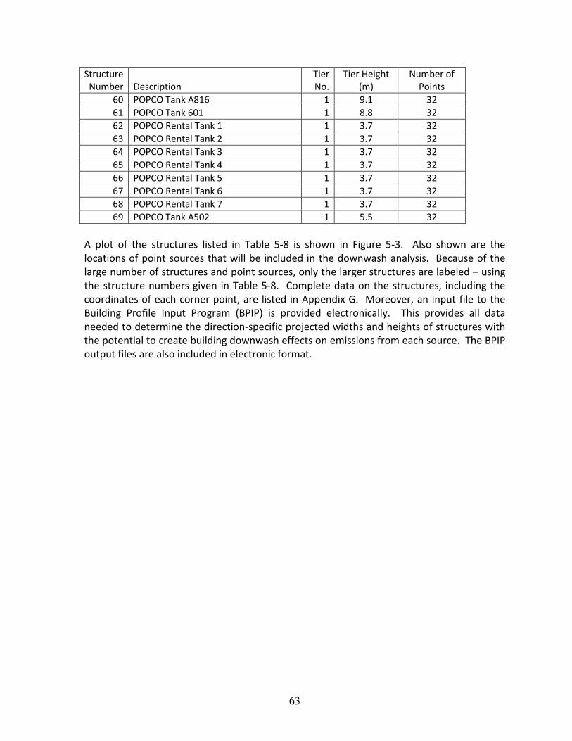
63
Structure
Number Description
Tier
No.
Tier Height
(m)
Number of
Points
60 POPCO Tank A816 1 9.1 32
61 POPCO Tank 601 1 8.8 32
62 POPCO Rental Tank 1 1 3.7 32
63 POPCO Rental Tank 2 1 3.7 32
64 POPCO Rental Tank 3 1 3.7 32
65 POPCO Rental Tank 4 1 3.7 32
66 POPCO Rental Tank 5 1 3.7 32
67 POPCO Rental Tank 6 1 3.7 32
68 POPCO Rental Tank 7 1 3.7 32
69 POPCO Tank A502 1 5.5 32
A plot of the structures listed in Table 5-8 is shown in Figure 5-3. Also shown are the
locations of point sources that will be included in the downwash analysis. Because of the
large number of structures and point sources, only the larger structures are labeled – using
the structure numbers given in Table 5-8. Complete data on the structures, including the
coordinates of each corner point, are listed in Appendix G. Moreover, an input file to the
Building Profile Input Program (BPIP) is provided electronically. This provides all data
needed to determine the direction-specific projected widths and heights of structures with
the potential to create building downwash effects on emissions from each source. The BPIP
output files are also included in electronic format.

64
Figure 5-3 Structures (green) and Point Sources (red)
Note: See Table 5-8 for the key to structure numbers
771400 771500 771600 771700 771800 771900 772000 772100
UTM Easting (m), NAD27, Zone 10
3819000
3819100
3819200
3819300
3819400
3819500
3819600
3819700
3819800
UT
M N
ort
hin
g (
m),
NA
D2
7,
Zo
ne
10
12
3
4
5
6
7
-
9
10
1112
13
14
15
16
17
2023
24 25
26
27
28
29 30
31
32
44
61

65
6 Schedule for ATEIR
ExxonMobil will coordinate with the APCD to develop a mutually agreeable schedule for
completing the ATEIR.

66
7 References
Bay Area AQMD, 2013. Permit Handbook, Ch. 11.1 Abrasive Blasting Operations, July 2013.
California Air Resources Board, 1988. Technical Support Document to Proposed Hexavalent
Chromium Control Plan, January 1, 1990.
California Air Resources Board, 1989. Technical Support Document for the Emission
Inventory Criteria and Guidelines Regulation for AB 2588, August 1989.
California Air Resources Board, 1991. Identification of Volatile Organic Compound Species
Profiles, Second Edition, August 1991.
California Air Resources Board, 2007. Speciation Profiles Used in ARB Modeling,
http://arb.ca.gov/ei/speciate/speciate.htm.
California Air Resources Board, 2007. California Air Toxics Emission Factor Database,
http://www.arb.ca.gov/ei/catef/catef.htm.
Office of Environmental Health Hazard Assessment (OEHHA)/California Air Resources Board
(CARB), 2013, Consolidated Table of OEHHA / ARB Approved Risk Assessment
Health Values, http://www.arb.ca.gov/toxics/healthval/contable.pdf.
Oilfield Environmental and Compliance, Inc. Stream Sampling and Analysis for POPCO and
Las Flores Canyon Facilities, Date to be Determined 2014.
San Diego, APCD, Welding Emission Calculations and Factors,
http://www.sdapcd.org/toxics/emissions/welding/welding.html, Last Updated:
1999.
Santa Barbara County APCD, 2001. Technical Information and References: ROC/VOC
Emission Factors and Reactivities for Common Source Types, Version 1.2, March 12,
2001.
U.S. EPA, 2013. Compilation of Air Pollutant Emission Factors (AP-42), Chapter 7 Liquid
Storage Tanks, Fifth Edition, November 2013.
U.S. EPA, 2000. Compilation of Air Pollutant Emission Factors (AP-42), Chapter 3.1
Stationary Gas Turbines, Fifth Edition, April 2000.
U.S. EPA, 1997. Compilation of Air Pollutant Emission Factors (AP-42), Chapter 13.2.6
Abrasive Blasting, September 1997.

67
U.S. EPA, 1996. Compilation of Air Pollutant Emission Factors (AP-42), Chapter 3.3 Gasoline
and Diesel Industrial Engines, Fifth Edition, October 1996.
U.S. EPA, 1995. Compilation of Air Pollutant Emission Factors (AP-42), Chapter 12.19
Electric Arc Welding, Fifth Edition, January 1995.
U.S. EPA, 1995. Compilation of Air Pollutant Emission Factors (AP-42), Chapter 13.5
Industrial Flares, Fifth Edition, January 1995.
Ventura County APCD, 2001. Ventura County APCD AB 2588 Combustion Emission Factors,
May 17, 2001.