aaShee - Hobson...125 35.4 19.6 175 44.1 23.2 Disclaimer: While every reasonable effort has been...
3
Disclaimer: While every reasonable effort has been made to ensure that this document is correct at the time of printing, Hobson Engineering, its agencies and employees, disclaim any and all liability to any person in respect of anything or the consequences of anything done or omitted to be done in reliance upon the whole or any part of this document. Release: January 25, 2017 www.conxtruct.com.au DataSheet Stud Anchor Dogpoint tip that prevent thread damage during installation Well designed wedge for reliable generation of expansion forces. CLAWBOLTS ® (Through Bolts) are pre- assembled single unit wedge type anchors used in solid concrete applications. Fixing is achieved by controlled torqueing of the nut which draws the tapered section up into the clip, thereby expanding it outward and forcing the CLAWBOLT ® against the sidewall of the pre-drilled hole. Because of the CLAWBOLT ® ’s unique features, it can be used for many fastening applications, including but not limited to the following: 2 3 4 Cold formed stud for security in performance Expansion clip with “claws” that grips onto the hole wall, initiating the expansion process. Suitable for light to medium duty loads Suitable for standard and reduced embedment depths Quick and easy to install Immediate loading is possible • Hand rail fastening • Formwork support fastening • Mechanical, electrical and pipe bracket fastening 1 Zinc Yellow Mechanically Galvanised Stainless Steel Optimized thread lengths for accomodating different fixture thicknesses. Three corrosion resistance options: Simple . Easy . Reliable .
Transcript of aaShee - Hobson...125 35.4 19.6 175 44.1 23.2 Disclaimer: While every reasonable effort has been...
Disclaimer: While every reasonable effort has been made to ensure that this document is correct at the time of printing, Hobson Engineering, its agencies and employees, disclaim any and all liability to any person in respect of anything or the consequences of anything done or omitted to be done in reliance upon the whole or any part of this document.
Release: January 25, 2017 www.conxtruct.com.au
DataSheetStud Anchor
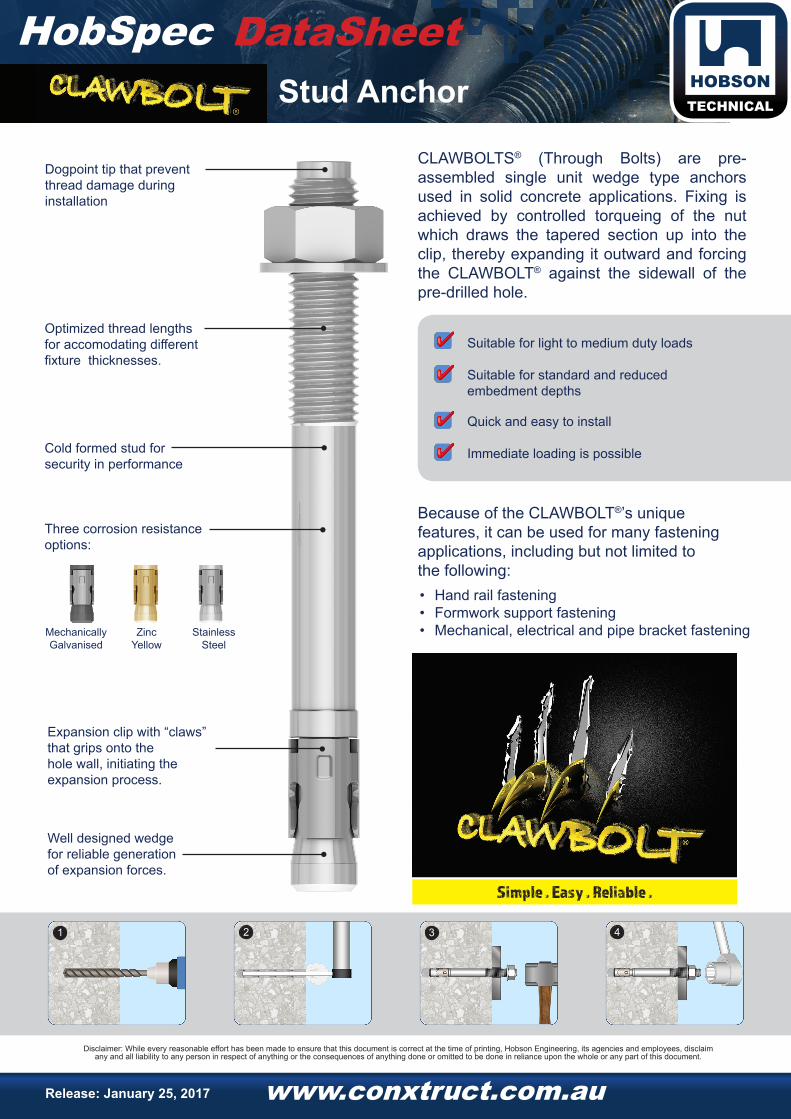
Dogpoint tip that prevent thread damage during installation
Well designed wedge for reliable generationof expansion forces.
CLAWBOLTS® (Through Bolts) are pre-assembled single unit wedge type anchors used in solid concrete applications. Fixing is achieved by controlled torqueing of the nut which draws the tapered section up into the clip, thereby expanding it outward and forcing the CLAWBOLT® against the sidewall of the pre-drilled hole.
Because of the CLAWBOLT®’s unique features, it can be used for many fastening applications, including but not limited to the following:
2 3 4
Cold formed stud forsecurity in performance
Expansion clip with “claws”that grips onto the hole wall, initiating the expansion process.
Suitable for light to medium duty loads
Suitable for standard and reduced embedment depths
Quick and easy to install
Immediate loading is possible
• Hand rail fastening• Formwork support fastening• Mechanical, electrical and pipe bracket fastening
1
Zinc Yellow
Mechanically Galvanised
Stainless Steel
Optimized thread lengthsfor accomodating differentfixture thicknesses.
Three corrosion resistance options:
Simple . Easy . Reliable .
Disclaimer: While every reasonable effort has been made to ensure that this document is correct at the time of printing, Hobson Engineering, its agencies and employees, disclaim any and all liability to any person in respect of anything or the consequences of anything done or omitted to be done in reliance upon the whole or any part of this document.
Release: January 25, 2017 www.conxtruct.com.au
DataSheetStud Anchor
1 Design Resistance is the governing minimum load resistance obtained by comparing relevant concrete and steel resistances. Capacity reduction factors of f = 0.60 for concrete and f = 0.80 for steel are already included.
2 Working Load is the governing minimum allowed load obtained by comparing relevant concrete and steel working loads. Factor of safety FOS = 2.5 for steel and FOS = 3.0 for concrete are already included.
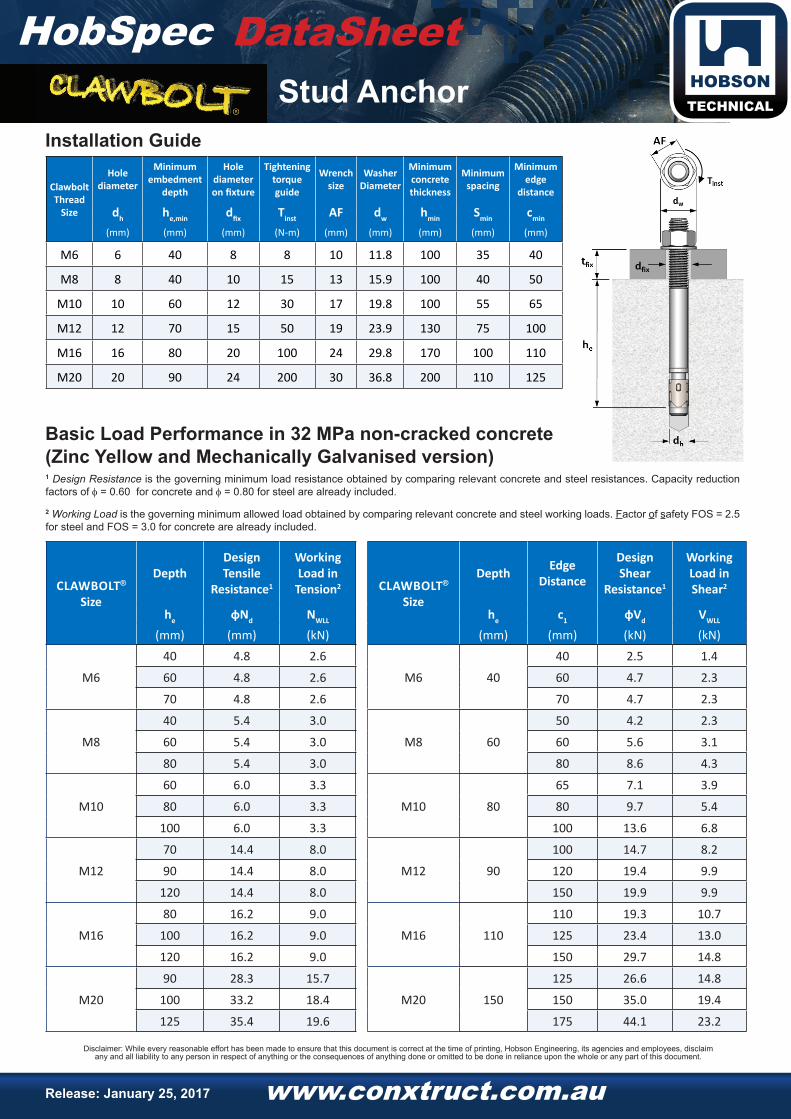
Installation Guide
Basic Load Performance in 32 MPa non-cracked concrete(Zinc Yellow and Mechanically Galvanised version)
Clawbolt Thread
Size
Hole diameter
Minimum embedment
depth
Hole diameter on fixture
Tighteningtorque guide
Wrench size
Washer Diameter
Minimum concrete thickness
Minimum spacing
Minimum edge
distance
dh he,min dfix Tinst AF dw hmin Smin cmin
(mm) (mm) (mm) (N-m) (mm) (mm) (mm) (mm) (mm)
M6 6 40 8 8 10 11.8 100 35 40
M8 8 40 10 15 13 15.9 100 40 50
M10 10 60 12 30 17 19.8 100 55 65
M12 12 70 15 50 19 23.9 130 75 100
M16 16 80 20 100 24 29.8 170 100 110
M20 20 90 24 200 30 36.8 200 110 125
CLAWBOLT®
Size
DepthDesignTensile
Resistance1
Working Load in
Tension2 CLAWBOLT®
Size
Depth EdgeDistance
DesignShear
Resistance1
Working Load in Shear2
he фNd NWLL he c1 фVd VWLL
(mm) (mm) (kN) (mm) (mm) (kN) (kN)
M6
40 4.8 2.6
M6 40
40 2.5 1.4
60 4.8 2.6 60 4.7 2.3
70 4.8 2.6 70 4.7 2.3
M8
40 5.4 3.0
M8 60
50 4.2 2.3
60 5.4 3.0 60 5.6 3.1
80 5.4 3.0 80 8.6 4.3
M10
60 6.0 3.3
M10 80
65 7.1 3.9
80 6.0 3.3 80 9.7 5.4
100 6.0 3.3 100 13.6 6.8
M12
70 14.4 8.0
M12 90
100 14.7 8.2
90 14.4 8.0 120 19.4 9.9
120 14.4 8.0 150 19.9 9.9
M16
80 16.2 9.0
M16 110
110 19.3 10.7
100 16.2 9.0 125 23.4 13.0
120 16.2 9.0 150 29.7 14.8
M20
90 28.3 15.7
M20 150
125 26.6 14.8
100 33.2 18.4 150 35.0 19.4
125 35.4 19.6 175 44.1 23.2

Disclaimer: While every reasonable effort has been made to ensure that this document is correct at the time of printing, Hobson Engineering, its agencies and employees, disclaim any and all liability to any person in respect of anything or the consequences of anything done or omitted to be done in reliance upon the whole or any part of this document.
Release: January 25, 2017 www.conxtruct.com.au
DataSheetStud Anchor
1 Design Resistance is the governing minimum load resistance obtained by comparing relevant concrete and steel resistances. Capacity reduction factors of f = 0.60 for concrete and f = 0.80 for steel are already included.
2 Working Load is the governing minimum allowed load obtained by comparing relevant concrete and steel working loads. Factor of safety FOS = 2.5 for steel and FOS = 3.0 for concrete are already included.
Basic Load Performance in 32 MPa non-cracked concrete(316 Stainless Steel version)
CLAWBOLT® Size
Depth Design Tensile Resistance1
Working Loadin Tension2
CLAWBOLT® Size
Depth Edge Distance
Design Shear Resistance1
Working Load in Shear2
he фNd NWLL he c1 фVd VWLL
(mm) (mm) (kN) (mm) (mm) (kN) (kN)
M8
40 8.4 4.6
M8 60
50 4.2 2.3
50 10.0 5.0 60 5.6 3.1
70 10.0 5.0 80 8.6 4.3
M10
60 15.4 8.5
M10 80
65 7.1 3.9
80 18.8 9.4 80 9.7 5.4
100 18.8 9.4 100 13.6 6.8
M12
70 19.4 10.8
M12 90
100 14.7 8.2
90 24.8 12.4 120 19.4 9.9
110 24.8 12.4 150 19.9 9.9
M16
80 23.8 13.2
M16 110
110 19.3 10.7
100 33.2 18.4 125 23.4 13.0
120 43.7 23.2 150 30.8 17.1
M20
90 28.3 15.7
M20 125
125 25.7 14.2
100 33.2 18.4 150 33.7 18.7
125 46.4 25.8 175 42.5 23.6