AAS 13-359 AUTONOMY ARCHITECTURE FOR A RAVEN …
20
AAS 13-359 AUTONOMY ARCHITECTURE FOR A RAVEN-CLASS TELESCOPE WITH SPACE SITUATIONAL AWARENESS APPLICATIONS Ryan D. Coder * and Marcus J. Holzinger † This paper investigates possible autonomy architecture designs of a Raven-class telescope as applied to the tracking and high level characterization problem in Space Situational Awareness (SSA). Various levels of autonomy are defined and existing systems and capabilities are discussed. Telescope interactions with dis- tributed sensor networks such as the Space Surveillance Network (SSN) are re- viewed, and several relationships between autonomy and scheduling of telescopes are addressed. An autonomy architecture design for a Raven-class telescope is presented and future extensions are proposed. RESEARCH MOTIVATION In 2001, the Rumsfeld Commission Report concluded that improvements in Space Situational Awareness (SSA) were needed to protect the US and its allies as well as maintain its economic and diplomatic objectives. 1 Joint Publication 3-14, Space Operations, defines the high level activi- ties included in SSA as the characterization and analysis of space objects (SOs) and environmental conditions interacting with space based assets. 2 Space objects consist of active and inactive satel- lites, rocket bodies, and orbital debris. 3 A key element of SSA is determining whether the orbits of SOs might bring them into close proximity, an event known as a “conjunction,” and the conditional probability of SO collision. 4 In order to establish a robust SSA capability, obtaining regular mea- surements is key. 5 The U.S. Stratetic Command (USSTRATCOM) Joint Space Operations Center (JSpOC) operates the Space Surveillance Network (SSN) and currently tracks 22,000 objects with diameters greater than 10 cm. 6 Additionally, NASA Johnson Space Center’s (JSC) Orbital Debris Program Office (ODPO) has primary responsibility for SO population below the SSN detection limit. 7 The need for persistent SSA has been exacerbated by both the Chinese anti-satellite test in 2007 8 and the Iridium/Cosmos collision in 2009, 9 both of which have increased the low-earth orbit (LEO) SO population by more than 60%. 10 The Space Surveillance Network (SSN) has historically been unable to collect enough raw mea- surements to fully characterize the SO population. 11 Hence, scheduling limited sensor resources to collect observations of the large SO population is a complex scheduling and resource allocation problem. While many efforts are currently under way to augment the current SSN with additional sensors, 7, 12 a great number of additional sensors with improved capability will increase the com- plexity of this scheduling and planning problem. When the space fence radar becomes operational, the number of tracked objects is expected to exceed 100,000. 4 In addition, modifying established schedules under dynamically evolving scenarios, inclement weather conditions, and hardware faults * Graduate Research Assistant, School of Aerospace Engineering, Georgia Institute of Technology † Assistant Professor, School of Aerospace Engineering, Georgia Institute of Technology 1
Transcript of AAS 13-359 AUTONOMY ARCHITECTURE FOR A RAVEN …

AAS 13-359
AUTONOMY ARCHITECTURE FOR A RAVEN-CLASS TELESCOPEWITH SPACE SITUATIONAL AWARENESS APPLICATIONS
Ryan D. Coder∗ and Marcus J. Holzinger†
This paper investigates possible autonomy architecture designs of a Raven-classtelescope as applied to the tracking and high level characterization problem inSpace Situational Awareness (SSA). Various levels of autonomy are defined andexisting systems and capabilities are discussed. Telescope interactions with dis-tributed sensor networks such as the Space Surveillance Network (SSN) are re-viewed, and several relationships between autonomy and scheduling of telescopesare addressed. An autonomy architecture design for a Raven-class telescope ispresented and future extensions are proposed.
RESEARCH MOTIVATION
In 2001, the Rumsfeld Commission Report concluded that improvements in Space SituationalAwareness (SSA) were needed to protect the US and its allies as well as maintain its economicand diplomatic objectives.1 Joint Publication 3-14, Space Operations, defines the high level activi-ties included in SSA as the characterization and analysis of space objects (SOs) and environmentalconditions interacting with space based assets.2 Space objects consist of active and inactive satel-lites, rocket bodies, and orbital debris.3 A key element of SSA is determining whether the orbits ofSOs might bring them into close proximity, an event known as a “conjunction,” and the conditionalprobability of SO collision.4 In order to establish a robust SSA capability, obtaining regular mea-surements is key.5 The U.S. Stratetic Command (USSTRATCOM) Joint Space Operations Center(JSpOC) operates the Space Surveillance Network (SSN) and currently tracks 22,000 objects withdiameters greater than 10 cm.6 Additionally, NASA Johnson Space Center’s (JSC) Orbital DebrisProgram Office (ODPO) has primary responsibility for SO population below the SSN detectionlimit.7 The need for persistent SSA has been exacerbated by both the Chinese anti-satellite test in20078 and the Iridium/Cosmos collision in 2009,9 both of which have increased the low-earth orbit(LEO) SO population by more than 60%.10
The Space Surveillance Network (SSN) has historically been unable to collect enough raw mea-surements to fully characterize the SO population.11 Hence, scheduling limited sensor resourcesto collect observations of the large SO population is a complex scheduling and resource allocationproblem. While many efforts are currently under way to augment the current SSN with additionalsensors,7, 12 a great number of additional sensors with improved capability will increase the com-plexity of this scheduling and planning problem. When the space fence radar becomes operational,the number of tracked objects is expected to exceed 100,000.4 In addition, modifying establishedschedules under dynamically evolving scenarios, inclement weather conditions, and hardware faults
∗Graduate Research Assistant, School of Aerospace Engineering, Georgia Institute of Technology†Assistant Professor, School of Aerospace Engineering, Georgia Institute of Technology
1

is difficult.11 The planning and scheduling is complicated by the fact that the current global net-work of SSN sensors are not exclusively controlled by the Air Force Space Command (AFSPC),but also by other entities that provide data to the command, such as foreign governments or othergovernment agencies (OGA) such as the Missile Defense Agency.4
Not only has the number of SOs tracked by the SSN greatly increased, but the data productsand services provided by JSpOC have a record number of customers as well. Currently more than100 countries as well as commercial satellite operators regularly request conjunctions assessmentsand launch screenings.4 This has greatly increased the workload of JSpOC, as human analystsare needed to catalog orbital debris, recover lost satellites from uncorrelated tracks, and ensurecomputer calculated answers are intuitively correct.13 Compounding this problem, the Air Forcehas faced several challenges concerning staffing a sufficient number of qualified analysts.4, 13
Outside of these current operational challenges, there is also room for improved utility of thesensors themselves. As previously discussed, as sensor assets with greater capabilities are broughtonline, a greater number of SOs will be able to be added to the current SSN catalog. Thus, Itwill become increasingly likely that in the process of completing an assigned observation, a sensorasset will detect additional SOs previously unknown, such as orbital debris, in the vicinity of spacearound the initial target. Due to the centralized planning yet distributed nature of current SSNsensors14 and the fast time scales involved in making SO observations,15, 16 decisions concerningfollow up observations are best made locally at the sensor location, and globally on time scales thatare incompatible with human in-the-loop decision making.
The large number of SOs, complex scheduling constraints, high human workloads, and short timescales are persistent challenges that are well suited to using autonomy approaches.17 The term ‘au-tonomy’ is often used to describe any system that can operate without human intervention.18 For thepurposes of this paper, autonomy will be discussed using the three levels of Intelligent Machine De-sign defined by NASA’s Goddard Space Flight Center (GSFC) for use in spacecraft.18 These threelevels, Reaction, Routine, and Reflection, are defined by increasing levels of autonomy. The mostbasic of the three, the Reaction level, is primarily responsible for processing sensor information andcommanding actuators over very short time scales. The Routine level is where routine evaluationand planning behaviors occur over medium time scales. Finally, the Reflective level is where highlevel planning, review, and learning occur over large time scales.
The core of an intelligent agent acting at the Reflective level is its ability to reason and learn aboutits environment. To discuss autonomous agents that learn, this paper will also utilize the three com-monly accepted types of learning. Each of these are categorized by the type of feedback availableto the agent for learning. In supervised learning, the agent observes input-output pairs and learns afunction which maps between them through techniques such as linear regression. In reinforcementlearning, an agent is presented with either a reward or punishment after taking some actions, andis tasked with learning which actions were most responsible for the presented reinforcement. Inunsupervised learning, no explicit feedback is provided to the agent to facilitate learning.19
Various levels of autonomy aside, sensor networks like the SSN are also examples of distributedsensor networks (DSNs). As applied to the tracking of SOs, DSNs “...may be classified as a non-linear consensus tracking problem on a time-varying graph with incomplete data and noisy com-munications links.”20 For DSNs, two primary goals are the scheduling and tasking of individualsensors, as well as the fusion of track information they generate. A major consideration when de-signing a DSN is whether the scheduling and planning problems are completed by a centralized
2

agent, distributed among multiple functionally or spatially distributed agents, or some combinationthereof.14 While distributed agents may be desirable from a design for robustness perspective, thevarying capabilities of distributed sensor assets may result in inconsistent SO state estimates.20 Theastronomical community has investigated the distributed networking and coordination of heteroge-neous telescope networks, pioneered by astronomers looking to improve observation response timeto Gamma Ray Burst (GRB) events.21
The proposed research presents an autonomy architecture for the Raven-class telescope system,and seeks to elevate the level of autonomy from “Routine” to “Reflection.”18 The Raven programbegan at the Air Force Research Laboratory (AFRL) Directed Energy Directorate’s Air Force MauiOptical and Supercomputing (AMOS) site. A Raven-class telescope system is not defined by aspecific combination of components. Rather, it is a design paradigm where commercial off-the-shelf (COTS) hardware and software are combined to fulfill the requirements set forth by a givenmission, such as precision tracking of SOs. Physically, the Raven system is a combination of severalphysical components: the telescope and dome, the CCD, control computer, the weather station, anda GPS receiver and timing system. While the Raven program initially started as an R&D effort,in 2001 a Raven located at the Maui Space Surveillance Site became a contributing sensor to theSSN.11 The low cost of COTS hardware coupled with the Raven’s history in R&D make it an idealresearch platform for an academic institution like the Georgia Institute of Technology.
This paper will present a loose history of autonomous telescopes and highlight current oppor-tunities for beneficial application of autonomy to SO tracking and characterization. A proposedautonomy architecture for a Raven-class Telescope (RCT) is then discussed and a notional envi-ronment learning agent is described. The autonomous agents discussed will be implemented on aRaven-class telescope at the Georgia Institute of Technology to form a multi-agent system, whichwill be verified by performing SSA research. This paper will then discuss how this MAS could fitinto a DSN like the SSN, along with directions for future work.
APPLICATION OF AUTONOMY
Past and Current Autonomous Telescopes
Telescopes have had various levels of autonomy over the last decades, starting with the first sched-uled telescopes in the 1960s.22 The Raven system at AMOS is capable of acting at the “Routine”level of autonomy. Using the weather station sensors, it can detect nautical twilight to begin auto-mated boot sequences and detect inclement weather to suspend operation. More impressively, givena set of tasks, it can determine an appropriate observation schedule to satisfy the human-providedobjectives.11
An existing autonomous telescope is the Meter-Class Autonomous Telescope (MCAT), deployedto Kwajalein Atoll in order to perform orbital debris observations for both NASA and the AFRL.MCATs mission is the detection of orbital debris in both low-inclination LEO orbits and at geosyn-chronous earth orbit (GEO), with detection limits of 2 and 10 cm diameters respectively. Also,MCAT is intended to observe targets of opportunity alongside Kwajalein range radar stations.MCAT was designed with autonomy in mind, and is planned to execute7 “Tasking, data acquisition,data reduction, and even some analysis aspects...” with “...minimal or optional” user intervention.
An example DSN of telescopes was Los Alamos’ Telescope ALert Operations Network (TALON).The TALON network server was comprised physically of RAPid Telescopes for Optical Response(RAPTOR) telescopes interconnected using standard TCP/IP protocols. Each RAPTOR had a
3

“client” agent which was responsible for transmitting data to a centralized server. This central-ized server synthesized these individual data logs to produce follow-up observation alerts whichwere pushed back to all telescopes connected to the TALON.23
Recently, detailed thought has been applied to moving telescope network autonomy to the Reflec-tive level. The Thinking Telescope program at Los Alamos National Laboratories has taken lessonslearned from TALON and has combined additional RAPTOR telescopes with unsupervised learningtechniques. The architecture consists of a vast database of observational variations from persistentsources coupled with intelligent agents. These agents learn over time to distinguish between actualgamma ray burst (GRB) events and environment noise such as airplane lights and other non-celestialphenomena.24
Cognition Models for Autonomy
When examining past and present autonomous systems, it is apparent that despite their differentapplications many systems share similar autonomous architecture. This is a result of the commongoals that an autonomous system must achieve, provided with similar means to achieve these goals.As autonomous systems become more intelligent, they ultimately strive to emulate the decisionmaking processes of humans. Of the many decision making processes, or cognition models, thatexist, perhaps one of the most widely known is the Observe, Orient, Decide, Act (OODA) loopproposed by John Boyd. Boyd is historically remembered for his part in the creation of Energy-Maneuverability theory and subsequent successes with the Air Force’s Lightweight Fighter pro-gram. While his theory was initially applied to military conflicts, it was later abstracted to busi-nesses, governments, and other societal structures.25
A basic diagram depicting Boyd’s OODA loop can be seen in Fig. 1 below. The first step,Observe, involves collecting data from the environment. The second step, Orient, describes theanalysis and synthesis of these observations in order to producing a current view of impression ofthe world. The next step, Decide, involves planning a course of action based on the current model ofreality. The last step, Act, is simply the step where action is taken in the environment. This actionimparts a last effect on the environment, the results of which are then observed, thus cycling theloop anew.25 Part of the success of the OODA loop is that Boyd supports his ideas by deriving itsbasic tenets from physics and mathematical principles.26
Boyd first utilizes Godel’s Incompleteness Theorem to posit that any “...physical systems weevolve to represent or deal with large portions of reality will at best represent or dealt with thatreality incompletely or imperfectly.”26 But, he then uses Heisenberg’s Uncertainty Principle and theSecond Law of Thermodynamics to postulate that “... any inward-oriented and continued effort toimprove the match-up of concept with observed reality will only increase the degree of mismatch.”27
He concludes that the only way to fully understand and shape an evolving, uncertain reality is toadapt the abstract models of reality, on which decisions are made, by continually cycling throughthe OODA loop.27 This principle seems to be of great relevance when designing an autonomoussystems that operative at the Reflective level of autonomy. In order for such a system to success-fully understand, synthesize, and interact with its environment, the underlying models of physicson which it makes decisions can not be static or unchanging with time. However, of the signifi-cant amount of research conducted in machine learning, most algorithms are implemented to solvesimple games with static environments, so that criteria for stability of the learning process or localoptimality can be established.28, 29 Thus, there is a need for a paradigm shift in the way currentautonomous systems learn.
4

Plan
Perceive Act
Orient
Decide
Act
Observe
Figure 1. Cognition Models
The inherent structure of the OODA loop is given further credence by the similarity of cognitionmodels developed by other entities. NASA Goddard describes a cognition model similar to theOODA loop, shown in Fig. 1. The only functional difference is that the Observe and Orient stepshave been collapsed into a single step, resulting in an architecture containing three steps: Perceive,Plan and Act. The Perceive step involves sensing and interpreting the operating environment. ThePlan step involves using information form the Perceive step to choose appropriate actions in pursuitof the goals and mission of the system. Finally, the Act step is simply the point in the autonomouscycle where action is taken in the environment.18
It is useful to conceptualize these cognition models in terms of a common classical control loop,as shown in Fig. 2. Here, the Observe steps can be thought of as the combination of system sensorsand relevant filtering or estimating software. The Orient step involves comparing the estimate of themeasured state to the reference or desired state. The Plan or Decide step uses the difference betweenthe desired and measured state to define a course of action, and the Act step is the interaction of theactuator with the physical plant.
Reference Generation Controller Actuator
Processing
Sensor Processing
Filter / Estimator
Decide Orient
Observe
Act
Real World
Figure 2. Cognition Model Visualized as Feedback Loop
Past and Current Autonomy Architectures
From these various cognition models spring the actual autonomy architectures which drive au-tonomous systems. The traditional architecture is comprise of three-tiers: the functional level, the
5
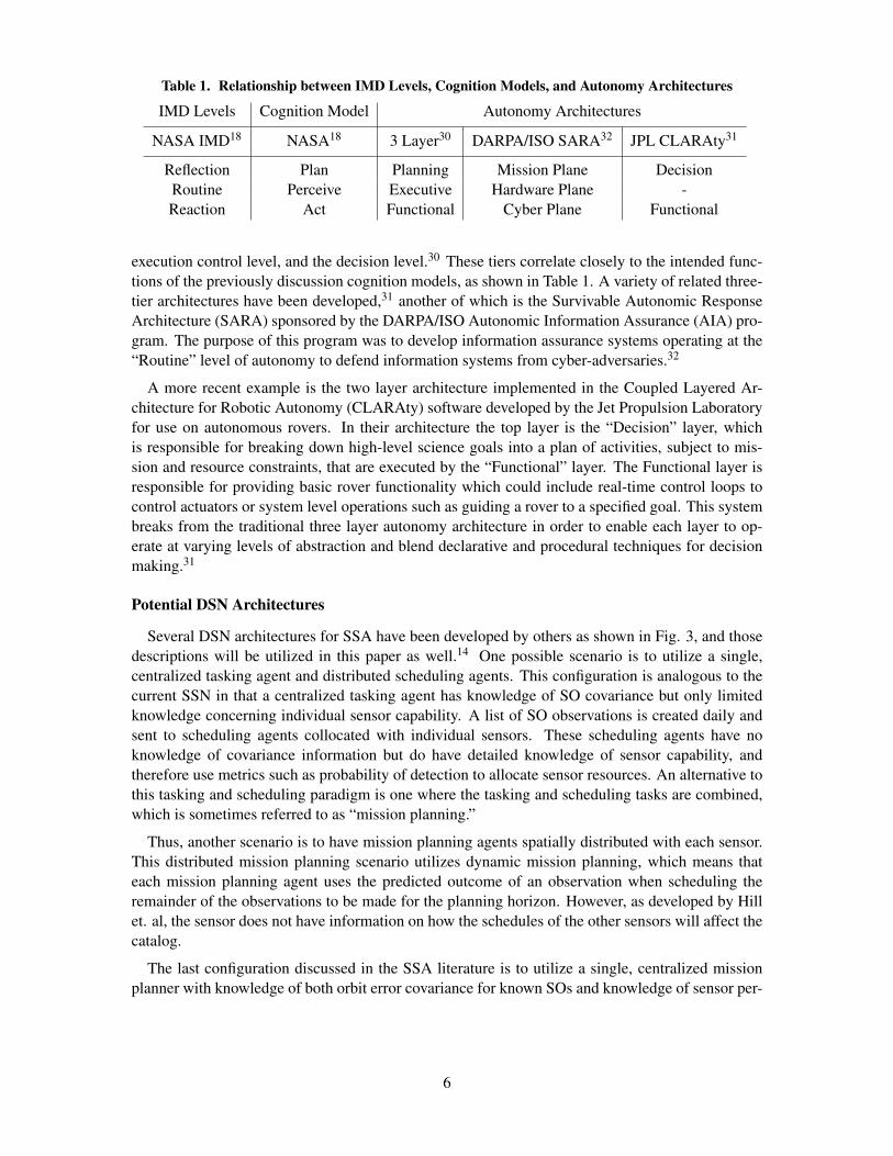
Table 1. Relationship between IMD Levels, Cognition Models, and Autonomy Architectures
IMD Levels Cognition Model Autonomy Architectures
NASA IMD18 NASA18 3 Layer30 DARPA/ISO SARA32 JPL CLARAty31
Reflection Plan Planning Mission Plane DecisionRoutine Perceive Executive Hardware Plane -Reaction Act Functional Cyber Plane Functional
execution control level, and the decision level.30 These tiers correlate closely to the intended func-tions of the previously discussion cognition models, as shown in Table 1. A variety of related three-tier architectures have been developed,31 another of which is the Survivable Autonomic ResponseArchitecture (SARA) sponsored by the DARPA/ISO Autonomic Information Assurance (AIA) pro-gram. The purpose of this program was to develop information assurance systems operating at the“Routine” level of autonomy to defend information systems from cyber-adversaries.32
A more recent example is the two layer architecture implemented in the Coupled Layered Ar-chitecture for Robotic Autonomy (CLARAty) software developed by the Jet Propulsion Laboratoryfor use on autonomous rovers. In their architecture the top layer is the “Decision” layer, whichis responsible for breaking down high-level science goals into a plan of activities, subject to mis-sion and resource constraints, that are executed by the “Functional” layer. The Functional layer isresponsible for providing basic rover functionality which could include real-time control loops tocontrol actuators or system level operations such as guiding a rover to a specified goal. This systembreaks from the traditional three layer autonomy architecture in order to enable each layer to op-erate at varying levels of abstraction and blend declarative and procedural techniques for decisionmaking.31
Potential DSN Architectures
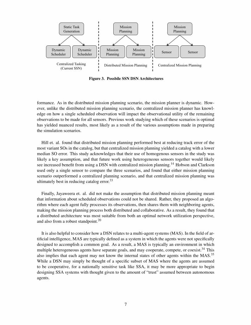
Several DSN architectures for SSA have been developed by others as shown in Fig. 3, and thosedescriptions will be utilized in this paper as well.14 One possible scenario is to utilize a single,centralized tasking agent and distributed scheduling agents. This configuration is analogous to thecurrent SSN in that a centralized tasking agent has knowledge of SO covariance but only limitedknowledge concerning individual sensor capability. A list of SO observations is created daily andsent to scheduling agents collocated with individual sensors. These scheduling agents have noknowledge of covariance information but do have detailed knowledge of sensor capability, andtherefore use metrics such as probability of detection to allocate sensor resources. An alternative tothis tasking and scheduling paradigm is one where the tasking and scheduling tasks are combined,which is sometimes referred to as “mission planning.”
Thus, another scenario is to have mission planning agents spatially distributed with each sensor.This distributed mission planning scenario utilizes dynamic mission planning, which means thateach mission planning agent uses the predicted outcome of an observation when scheduling theremainder of the observations to be made for the planning horizon. However, as developed by Hillet. al, the sensor does not have information on how the schedules of the other sensors will affect thecatalog.
The last configuration discussed in the SSA literature is to utilize a single, centralized missionplanner with knowledge of both orbit error covariance for known SOs and knowledge of sensor per-
6
Static Task Generation
Dynamic Scheduler
Dynamic Scheduler
Mission Planning
Mission Planning
Mission Planning
Mission Planning
Sensor Sensor
Centralized Tasking (Current SSN)
Distributed Mission Planning Centralized Mission Planning
Figure 3. Possbile SSN DSN Architectures
formance. As in the distributed mission planning scenario, the mission planner is dynamic. How-ever, unlike the distributed mission planning scenario, the centralized mission planner has knowl-edge on how a single scheduled observation will impact the observational utility of the remainingobservations to be made for all sensors. Previous work studying which of these scenarios is optimalhas yielded nuanced results, most likely as a result of the various assumptions made in preparingthe simulation scenarios.
Hill et. al. found that distributed mission planning performed best at reducing track error of themost variant SOs in the catalog, but that centralized mission planning yielded a catalog with a lowermedian SO error. This study acknowledges that their use of homogenous sensors in the study waslikely a key assumption, and that future work using heterogeneous sensors together would likelysee increased benefit from using a DSN with centralized mission planning.14 Hobson and Clarksonused only a single sensor to compare the three scenarios, and found that either mission planningscenario outperformed a centralized planning scenario, and that centralized mission planning wasultimately best in reducing catalog error.33
Finally, Jayaweera et. al. did not make the assumption that distributed mission planning meantthat information about scheduled observations could not be shared. Rather, they proposed an algo-rithm where each agent fully processes its observations, then shares them with neighboring agents,making the mission planning process both distributed and collaborative. As a result, they found thata distributed architecture was most suitable from both an optimal network utilization perspective,and also from a robust standpoint.20
It is also helpful to consider how a DSN relates to a multi-agent systems (MAS). In the field of ar-tificial intelligence, MAS are typically defined as a system in which the agents were not specificallydesigned to accomplish a common goal. As a result, a MAS is typically an environment in whichmultiple heterogeneous agents have separate goals, and may cooperate, compete, or coexist.34 Thisalso implies that each agent may not know the internal states of other agents within the MAS.35
While a DSN may simply be thought of a specific subset of MAS where the agents are assumedto be cooperative, for a nationally sensitive task like SSA, it may be more appropriate to begindesigning SSA systems with thought given to the amount of “trust” assumed between autonomousagents.
7

Challenges in Autonomy
As autonomous systems utilize increasingly intelligent behavior, a variety of challenges presentthemselves. NASA and the National Research Council (NRC) have identified several areas of au-tonomy research as key enablers to future success of U.S. space efforts. This includes research inthe area of dynamic planning, sequencing tools, and multi-agent systems. Specific challenges withplanning and scheduling tools are the ability to rapidly explore the action space, repair complexplans, and develop commands with traceability to the initial activity requirements. They also iden-tify current challenges in multi-agent systems, including management of agent system group goaldirection.36, 37
The desire for more capable autonomous systems is also evident in recent Air Force TechnologyRoadmaps, which describes dozens of potential future capabilities and then selects four “GrandChallenges” to help guide Air Force Science and Technology efforts. Number 2 on the list is“Trusted Highly-Autonomous Decision-Making Systems,” which is concerned with developing au-tonomous decision-making agents in parallel with generalized V&V methods that can be appliedto a broad range of problems rather than application specific agents. There is a specific focus onsystems which decrease human workload and are capable of operating at decision time scales be-yond human capacity. Number 3 on the list “Fractionated, Composable, Survivable, AutonomousSystems” is concerned with designing robust, secure networks of autonomous systems almost syn-onymous with the definition of a DSN. The Air Force’s top priority in this area is the developmentof advanced methods for collaborative control and adaptive autonomous mission planning. There isspecial verbiage to emphasis the importance of these systems in increasing mission robustness, notnecessarily mission capability, through system redundancy.12
In order to mitigate these issues, this paper discusses a proposed multi-agent system that canreason about interdependent science and mission objectives and coordinate host sensor efforts. Thispaper is concerned mainly with high level autonomous activities, motivating the development oftwo distinct agent types: a dynamic scheduling and planning agent and a learning agent. As a spacemission platform analog, a single instance of each agent type will be implemented on a Raven-classtelescope for the purpose of performing SSA.
PROPOSED RAVEN-CLASS TELESCOPE AUTONOMY ARCHITECTURE
Proposed DSN and Autonomy Architecture
From the work conducted independently by Hill and Jayaweera, it was demonstrated that DSNare most efficient when spatially disparate sensors have knowledge about the mission planningactivities of one another. In order to demonstrate how these gains can be realized in a systemonly incrementally different than the current SSN, the proposed autonomy architecture for the RCTwill utilize centralized tasking, as shown in Fig. 4. Task scheduling will be completed locally ateach Raven by a single, dynamic scheduling agent, referred to as the “CSP agent” as explained inthe following section. The authors hypothesize that modern computers have enough computationalcapability to enable search algorithms to dynamically change observation schedules using only theresources of a single CSP agent. In future research efforts, the CSP agent could be made a missionplanning agent. These agents could then be replicated on every sensor, creating a distributed missionplanning capability that would be robust to communication link failures.
In order for the CSP agent to construct accurate schedules, knowledge about observational metricslike “probability of SO detection” and “mean time to detect SOs” are needed. This information
8

Agent&
Raven&Class&Telescope&
Central&Planning&
Agent&
…& Other&networked&sensors&
Increasing&Machine&
Intelligence&
Reflec=on&
Rou=ne&
Reac=on&
Commanded&Objec=ves&
Agent&Agent&
Agent&Agent&Agent&
Agent&Agent&Agent&
Space&Object&Catalog&
Figure 4. Proposed Georgia Tech Raven DSN
will be provided by a learning agent, referred to as an “RSM” agent as explained shortly. Theseagents will be developed as part of a traditional three layer architecture. The remainder of the paperis concerned mainly with the two highest levels of autonomy, and the two agents are segregatedfunctionally as shown in Fig. 5. The RSM agent acts at the “Reflective” level of autonomy, whilethe CSP agent at the “Routine” level of autonomy.
Local Scheduling and Planning with Constraint Satisfaction
Within the task of SSA, the domain of possible actions and SO targets is vast, and the timescalefor decision making between initial SO detection and follow up observations could be as low asfractions of seconds.16, 15 Thus, the scheduling agent must be able to rapidly explore the designspace in order to locally repair complex schedules. One potential solution is to cast the planningand scheduling problem as a Constraint Satisfaction Problem (CSP), and thus this agent will bereferred to as the “CSP agent.” CSPs have the advantage of using general purpose heuristics, andthus are applicable to a wide range of problems. Additionally, CSPs can identify which partialschedules are not solutions to the problem constraints and immediately remove schedules which arerefinements of these infeasible solutions. This means CSPs are appropriate for problems where asolution via state-space search algorithms would be formidable.19
RSM
CSP
Functional
Inte
llige
nce
Reflective
Routine
Reaction
Figure 5. Intelligence hierarchy of local agents on the Georgia Tech RCT
9
Various CSP algorithms have been successfully used in the past to schedule astronomical obser-vations for space telescopes such as the Hubble Space Telescope,38 Chandra X-Ray Observatory,39
and the Spitzer Space Telescope.40 Also, CSPs have been utilized to identify opportunistic sciencetargets,41 prioritize science data downlinks,41 as well as guide the actions of autonomous rovers.31
A large number of these applications were built on top of the Continuous Activity Scheduling, Plan-ning, Execution and Re-planning (CASPER) continuous planner. CASPER primarily utilizes aniterative repair search algorithm, which permits continuous modification and updating of a currentworking plan as well as incremental planning and scheduling.42 Recent efforts have also demon-strated how CASPER could be modified to consider the interdependency of specified goals.43
The problem facing the CSP agent is to identify a sequence of activities that meet operationalconstraints and maximize utility of the schedule. In the Raven system, a span of time for eachnight, denoted t ∈ [ti, th], will be treated as a discrete planning horizon. CSPs are typically solvedvia the construction of action trees; a sequence of feasible decision points where each decision istermed a node. Thus, at each node there is a set of activities, A, each associated with a requiredamount of time tAi and an expected utility.19 The current notional concept of operations includesthe following activities: K (known), observing known SOs, S (search), searching the regions of thesky with the highest probability of new SO detections, and L (learn), making observations in regionsof the sky where little is currently known about the relationship between environmental states andtelescope performance metrics. As currently envisioned, known SOs could be human provided orcentral planner generated objectives would be input as high-level goals and could include commandslike “track catalog object number x” or “refine the orbital element estimates of SOs whose currentorbital element covariance is in the highest 10% of the catalog population.” With these activitydefinitions, the set of possible activities could be A = {K,S, ..., L∩S, ...}. The system constraints,C, are imposed by mechanical limitations of the Raven hardware and environmental variables likeweather, which could change the planning horizon length.
A multitude of algorithms exist that can be used to explore the activity tree, identify feasibleschedules, and select a desirable activity schedule.19 Using the notation developed here, a possiblefeasible schedule that satisfied all constraints is an ordered set S(ti, th) = {L,H, ...L ∩ S}. It iscommon for many such schedules to satisfy all the constraints, therefore utility functions will beused to determine which ordered set of events is preferable. While this utility based methodologyhas been extensively proven, each CSP is application specific, so one contribution of the proposedfuture research will be the development of novel utility functions that are both accessible to multipleagents and appropriate for the SSA problem. Initial utility functions could seek to maximize the totalnumber of detections while minimizing false positive and false negative detections, or weight theimportance of observing objects with the highest uncertainty in orbital ephemeris.
The CSP agent described implemented on a RCT would be an ideal testbed where various algo-rithms could be tested for timeliness in exploring action spaces and proficiency at repairing intricateplans. However, to trace telescope actions to initial requirements, it is necessary for the CSP agentto have knowledge about the current environment states and their relationship to each Raven per-formance parameter of interest. Examples include “probability of successfully detecting target Agiven current cloud cover” for actionH or “mean time to detect new SOs in a specified region of thesky” for action S. One possible method to generate this information is constructing an elaborate,physics-based model, specific to the particular Raven’s components and local environment. This isnot always possible or desirable, as sophisticated models are often computationally expensive andmay need to be calibrated for every Raven in the proposed multi-telescope system. Additionally,
10

there are not always analytical relationships between dynamic environmental variables of interestand telescope performance. Thus, the next goal of the proposed approach seeks to rectify this withthe development of a learning agent, which rigorously combines information theory and systemsengineering principles to develop a physics-based model that is both flexible and computationallyefficient.
Learning with Response Surface Methodology
Thus far, it has been shown that in order to form effective models of the environment in whichautonomous systems act, the system must be capable of constantly adapting to a changing reality.Historically, this has meant that autonomous systems have been built using machine learning tech-niques with a variety of assumptions, such as static environments, so that criteria for stability of thelearning process or local optimality can be established. However, this has limited their usefulness inreal world applications.28, 29, 34, 35, 44 Therefore, in order for the intelligent agents of an autonomoustelescope to be capable of learning about the ever-changing world they operate in, new machinelearning techniques are needed.
This paper proposes that the techniques developed in the fields of systems engineering can beleveraged to form a cross-cutting autonomous solution to serve as the basis for learning agent. Theproposed learning agent utilizes Response Surface Methodology (RSM), which encompasses designof experiments (DoE) and response surface equations (RSE) techniques, and will be referred to asthe “RSM agent.” The area of artificial intelligence most closely associated with these techniques iscalled “active learning.”45
The basic concept of active learning is that a machine learning algorithm can achieve greater pre-dictive capability with fewer sample data points in its training set if it is allowed to select which datapoints it uses to learn. The common assumption often made as the motivation for the developmentof these techniques, is that an abundance of unlabeled data is available or easily obtained, but thecorrect labels for these data points is difficult, time consuming, or expensive to obtain. Thus, mosttechniques seek to solve an unsupervised learning problem where the machine makes queries bychoosing which data points it wishes to learn with, and then the correct labels are provided by an“oracle,” typically a human operator.45
Before discussion the application of RSM, it is helpful to define some standard terms and theirsynonyms for those unfamiliar with these techniques. A “design variable”, also termed a “factor”or “parameter,” is a quantity varied during the experiment. Design variables can be discrete orcontinuous and are typically represented as an nx1-dimensional vector x . The “design space” isthe n-dimensional space defined by the upper and lower bound of each design variable. In manyclassical DoE texts the design space is scaled from−1 to 1 or from 0 to 1, which was a conveniencefor representing sample DoE tables, as well as a mathematical necessity for avoiding ill-conditionedmatrices when generating DoE samples. Today, DoE generation is conducted almost exclusively viacomputer programs, so it is not a concern of the human analyst to normalize design variable ranges.A “sample,” also synonymous with “design point” and “point,” is a specific instance of each designvariable x and is usually represented an an ordered n-tuple of the form (x1, x2, ..., xn). Finally, the“response” is the dependent quantity being measured by the experiment for a specific sample.46
Response Surface Methodology “...comprises a group of statistical techniques for empirical modelbuilding and model exploitation.”47 RSM approximates the relationship between the design vari-ables and the response over the entire response space, not unlike a supervised learning process in
11

the field of artificial intelligence.19 This approximation, termed the “response surface” or “responsesurface equation” (RSE), usually takes the form of a low order Taylor Series Expansion.48, 49 Whilethe RSE could take other forms, such as a Fourier Series, empirical evidence has shown that inmost cases a 2nd order Taylor Series approximation is sufficient.49 Synonyms for response surfaceequation include “model,” “metamodel,” or “surrogate model.”48 Finally, it should be noted thatthe statistically community uses the term response surface to denote the true unknown relationshipbetween the design variables and the response. In this case, the term “response surface approxima-tion” is used to describe the assumed form of the relationship between the design variables and theresponse.46
RSM has been used to characterize and study responses, determine design variables which re-sult in an optimal response, select design variables which result in a robust response, and for theprediction of new responses.49, 50 RSM allows the modeling of responses to design variables whenno empirical relationship is known, and the simplified equations of RSM allow for rapid evaluationand exploration of the design space. With an assumed polynomial form there is a known minimumnumber of data samples necessary to create an RSE. For a second-order polynomial, the numberof samples is given by samples = (n + 1)(n + 2)/2. In RSM, the exact samples to be used areselected through a design of experiments.
Generally, a DoE is a process where purposeful changes are made to input variables such thatresultant changes in output response may be observed and identified using a minimum numberof experiments.48 These methods were popularized in work determining optimum conditions forchemical processes,51 but have since had an enormous impact on variety of scientific and engineer-ing studies.49 However, since these techniques have been used in such a variety of fields, someconfusion has developed with regards to both terminology, as discussed above, and the appropriateuse different DoE designs.46
Perhaps the most overlooked facet of DoE is the fact that classical DoE methods, which includeBox-Behnken and Central Composite Designs, were developed for industrial processes which as-sumed the processes being analyzed were inherently non-repeatable. As a result, these designstypically select sample points at the extremes of the design variable ranges, resulting in more re-liable trend extraction from non-repeatable experiments. However, modern DoE methods weredeveloped with deterministic computer simulated experiments in mind. Hence, these designs, suchas sphere-packing designs, assume there is no random error in the sample data and place samplepoints throughout the interior of the parameter space in an effort to minimize bias error.46
Other computer generated DoE include “optimal designs”, which produce DoE that maximize theoptimality criteria of the DoE. Optimality criteria are characterized by the letters of the alphabet,and hence are sometimes referred to as alphabetic optimality criteria.49 Perhaps the most popularof these designs is the D-optimal design,45, 46, 49 which maximizes the determinant of the Fischerinformation matrix, reducing the square of the volume of the confidence region on the regressioncoefficients.49 Table 2 demonstrates the efficacy of two different DoE techniques compared to a fullfactorial exploration of the design space when a 2nd order Taylor Series approximation is used.48
In the Raven system each experiment can be an observation, and in order to determine the effectof an input variable, like sky brightness, on the probability of SO detection, a response, observa-tions could be taken at different levels of sky background brightness. A response surface equationcould then be fit to the collected sample points to form a physics-based model of the affect of skybrightness on SO detection, for the purpose of providing performance information to the CSP agent.
12

Table 2. Comparison of Required Experiments
DoE Experiments for n = 8 Variables Equation
Full Factorial 6561 3n
Central Composite 273 2n + 2n+ 1D-Optimal 45 (n+ 1)(n+ 2)/2
Data available on other Ravens suggests that the required amount of data could be collected in a fewnights.11
Unfortunately, the traditional DoE techniques discussed above are not suited to the Raven systemfor two main reasons. The first is many of the variables which contribute to telescope performanceare not controllable by the RSM agent, but are properties of the SO, such as angular velocity, orenvironmental properties, such as light pollution in the background sky.16, 15 The second is thatthese variables are not all independent of one another, a violation of classical designs. One solutionis to formulate the task of collecting observations as an unsupervised learning process. Recent workhas shown how non-orthogonal DoE designs, such as D-optimal designs, can be found from largedatabases, suggesting the DoE process can be autonomous.52 Since no algorithm currently existsto explicitly find orthogonal plans in non-binary data, genetic algorithms (GA) and kernel meth-ods have been utilized to find nearly orthogonal data points.53 While promising, these results wereobtained offline, with no consideration given to computational efficiency, motivating further inves-tigation to prove utility for an operational Raven system. Interesting areas of further inquiry wouldbe the implementation of alternative heuristic search patterns, such as particle swarm optimization(PSO).54 The general claim that PSO has the same capability to find the global optimal solution asa GA but with significantly better computational efficiency has been demonstrated.55 Additionalitems of interest include determining whether designs based on alternative alphabetic optimalitycriteria49 are quicker to find, and what threshold of orthogonality is necessary to construct accurateRSE.
It should be noted that the RSE process described here has two limitations. The first is the re-quirement that the state spaces in question are homogenous, comprised of either all continuous orall discrete variables. The second is that the dimensionality of input variables allowed for modeldevelopment be limited to approximately 10. However, a common method for circumventing thislimitation is known as an “effects screening test”, which, analogous to Pareto’s Law, has qualita-tively shown that approximately 20% of the input variables account for 80% of the variability ofthe response, ensuring its applicability to systems with a greater number of states.48 Other chal-lenges include automating the process of evaluating the “goodness of fit” metrics of the RSE, a tasktypically completed by human operators. Metrics for evaluating the accuracy of RSE include the co-efficient of determination, actual by predicted and residual by predicted plots, as well as Model FitError and Model Representation Error. Common remedies for poor fit, including logarithmic trans-formations and the inclusion of higher order terms, are rigorously defined and thus well suited toautomation.48 While both fixes necessitate extra computational cost, the second calls for additionalobservations to be performed.
The proposed RSM agent combines information theory and systems engineering methodologiesto autonomously select observations to approximate the relationship between various environmentalparameters and telescope performance for which no analytical models exist. The RSE generated arephysics-based and can change in a real world dynamic environment. This enables the CSP agent
13

to predict future performance, justifying why certain actions were selected over others in order tosatisfy initial requirements. Also, evaluation of the proposed RSEs are computationally inexpensive,ensuring their applicability to problems with fast timescales, like new SO detection.
RESPONSE SURFACE METHODOLOGY EXAMPLE
An example is now provided to further clarify the RSM agent concept, and demonstrate howthe RSM agent could supply the CSP agent with the probability of successfully observing a knownSO. The architecture for this example is shown in Fig. 6. Fig. 7 depicts a typical cloudy night inAtlanta, GA. These pictures, taken in the span of 4 hours on January 6th 2013, show how rapidlyenvironmental factors like cloud cover and aircraft overflights can change SO viewing opportunities.These pictures were collecting using the AllSky340 manufactured by SBIG. The AllSky340 usesa 640x480 pixel Kodak KAI-340 CCD, and a F/1.4 Fujinon fisheye lens. The AllSky340 wasconnected to a laptop via RS-232 and was programmed to automatically take pictures in two minutesintervals.
Raven&Class&Telescope&
Central&Planning&
Agent&
…& Other&networked&sensors&
Increasing&Machine&
Intelligence&
Reflec=on&
Rou=ne&
Reac=on&
Commanded&Objec=ves&
RSM&Agent&
CSP&Agent&
Func=onal&Agent&
Space&Object&Catalog&
Figure 6. Example Raven DSN
To ensure the CSP can make the best decision possible in a highly dynamic environment, it isnecessary for the RSM agent to calculate the probability of successful SO observation as a functionof environmental variables not under control of the Raven. One way to quantify the probability ofdetection is to utilize the signal to noise ratio (SNR) of the optical observation of the SO. It shouldbe stressed that SNR here refers to the ratio of the average signal value to the standard deviation ofthe background signal.15 Eq. 1 below gives a simplified form of the SNR as developed by Shell.16
SNR =ESO · τatm · τopt ·A ·QE · tint√(Lb · τopt ·A ·QE · tint · µ2) + e2n
(1)
In this equation the quantity ESO is the irradiance of the space object, the transmittance of theatmosphere and optics are represented by τ , A is the aperture of the telescope, QE is the quantumefficient of the detector, and µ is the instantaneous field of view. The signal integration time istint and en is the read noise of the detector. Many of these parameters, including the quantum
14
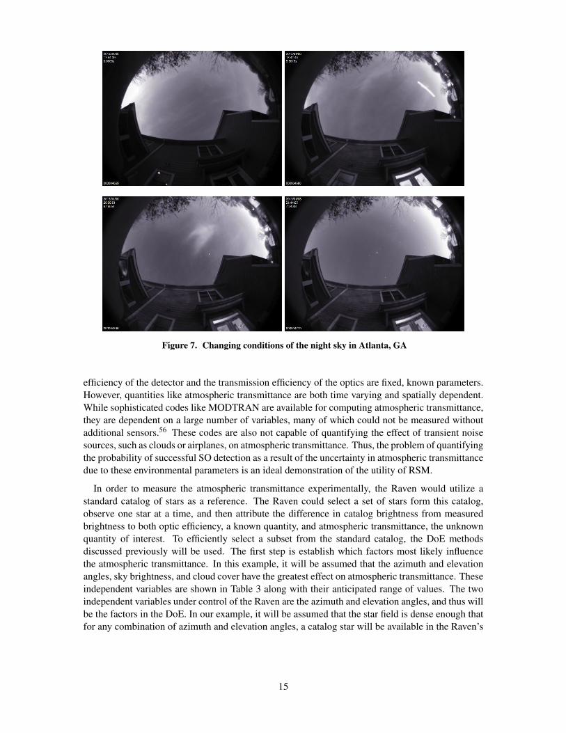
Figure 7. Changing conditions of the night sky in Atlanta, GA
efficiency of the detector and the transmission efficiency of the optics are fixed, known parameters.However, quantities like atmospheric transmittance are both time varying and spatially dependent.While sophisticated codes like MODTRAN are available for computing atmospheric transmittance,they are dependent on a large number of variables, many of which could not be measured withoutadditional sensors.56 These codes are also not capable of quantifying the effect of transient noisesources, such as clouds or airplanes, on atmospheric transmittance. Thus, the problem of quantifyingthe probability of successful SO detection as a result of the uncertainty in atmospheric transmittancedue to these environmental parameters is an ideal demonstration of the utility of RSM.
In order to measure the atmospheric transmittance experimentally, the Raven would utilize astandard catalog of stars as a reference. The Raven could select a set of stars form this catalog,observe one star at a time, and then attribute the difference in catalog brightness from measuredbrightness to both optic efficiency, a known quantity, and atmospheric transmittance, the unknownquantity of interest. To efficiently select a subset from the standard catalog, the DoE methodsdiscussed previously will be used. The first step is establish which factors most likely influencethe atmospheric transmittance. In this example, it will be assumed that the azimuth and elevationangles, sky brightness, and cloud cover have the greatest effect on atmospheric transmittance. Theseindependent variables are shown in Table 3 along with their anticipated range of values. The twoindependent variables under control of the Raven are the azimuth and elevation angles, and thus willbe the factors in the DoE. In our example, it will be assumed that the star field is dense enough thatfor any combination of azimuth and elevation angles, a catalog star will be available in the Raven’s
15

Table 3. Raven RSM Design Variables
Factor Anticipated Range (Units)
Azimuth (α) 0− 360 (deg)Elevation (δ) 0− 90 (deg)
Background Radiance (Lb) 14− 21 (mag/asec2)Cloud Cover (C) (C(α, δ)) (%)
Table 4. Compiled DoE Table
Obs. α (degrees) δ (degrees) Lb
( magasec2
)C (α, δ) (%) τatm (%)
#1 45.5 36.9 17 .58 .6#2 160 45.6 18 .2 .65...
#15 185 50 19 .43 .7
FOV. This scenario is known as “query synthesis” in the active learning literature.45
To minimize the number of observations necessary for building this model, thus freeing up timefor operational observations, one of the optimal DoE designs, such as a D-optimal design, couldbe used. In the field of active learning, a query strategy that synthesizes new samples to reducethe variance of the model in exactly the same way as a D-optimal design is appropriately named a“variance reduction” strategy.45 Because the initial assumption was that the relationship betweenthese variables and the SNR of the observation is quadratic the minimum number of stars to observeis 15. For each observation, the value of each environmental variable will be recorded along with theatmospheric transmittance of the captured image containing the SO. Because the background skybrightness and percent cloud cover variables are not controllable, the value at the time of observationwill simply be recorded along with the response, and the compiled results would appear as they doin Table 4. Please note that all data in this example is meant to be representative only and has notbeen taken from actual observations.
With the subset of observations selected, the linear least squares process can begin, creatingthe RSE. If every possible variable and resulting interaction term was included in the RSE, thisexample RSE would have 15 terms. This RSE can now be used for the purposes of predicting futureperformance of the Raven system when tasked with observation known SOs. Fig. 8 illustrates thecompleted RSM process, where the cartoon stars signify the catalog stars used in the DoE, and thebrighter contours represent areas of greater atmospheric transmittance, which could be obscured bycloud cover.
In this case, the azimuth and elevation angles may be known precisely, but other variables likebackground radiance or cloud cover could be assigned probability distributions that, through MonteCarlo simulation, yield a cumulative distribution function of the atmospheric transmission duringa future SO observation. This distribution can be used directly with the SNR given by Eq. 1 toyield a cumulative distribution function of the SNR of a future SO observation. This cumulativedistribution function, combined with a user selected minimum required SNR, allows the probabilityof successfully conducting the observation of the known SO, as shown in Fig. 8. In this example,the minimum required SNR was specified as six, which by looking at the CDF, one can see that thisimplies about a 80% chance of successfully observing the SO.
16

CONCLUSION
A loose history of autonomous telescopes was presented along with two common cognition mod-els that functionally decompose tasks common to autonomous systems. It was found that these twocognition models were very similar, despite development by two different organizations. Autonomyarchitectures that were developed based on these common tasks were discussed, along with possibleSSN DSN architectures. These autonomous architectures were found to be very similar, empiricallydemonstrating that a traditional 3-layer autonomy architecture was suited to a diverse range of prob-lems, including telescope autonomy. The brief survey of previous SSN DSNs work demonstratedthat spatially disparate sensors are most efficient when knowledge about mission planning activitiesare shared between one another. Using these findings, the proposed DSN and autonomy architec-ture for a Raven-class Telescope (RCT) was then described. The proposed autonomy architectureseeks to utilize the traditional 3-layer architecture, wherein increasingly intelligent agents are builtto handle increasingly complex tasks. Additionally, the DSN architecture proposed represents anincremental change from the current SSN, where a dynamic scheduling agent termed the “CSP”agent is used to perform local schedule repair. The functions of each intelligent agent were detailedalong with requisite background information. Here, consideration was given to solving the dynamicmission planning problem as a constraint satisfaction problem. Additionally, cutting edge method-ologies from both systems engineering, information theory, and machine learning were synthesizedinto a single intelligent agent, termed the “RSM” agent. The specific implementation of theseagents was explained using a tractable SSA example, where the MAS of a single Raven is taskedwith learning the dynamic, local atmospheric transmittance and the resultant impact on probabilityof SO detection.
FUTURE WORK
The implementation of the CSP and RSM agents on a single Raven will constitute a multi-agentsystem. This will serve as a platform to study the complex inter-agent dynamics typical of a MAS.For example, the RSM agent could learn that observations taken in the region of sky between 30◦
and 50◦ elevation have historically resulted in a greater number of previously unknown SO detec-tions. Accordingly, the CSP agent repairs the current plan to include more observations in thisregion of the sky, resulting in greater system utility.
2 4 6 8 10 120
0.2
0.4
0.6
0.8
1
SNR
Pro
ba
bili
ty t
he
Ob
se
va
tio
n S
NR
Exce
ed
s
Monte Carlo SNR
Reqd SNR
Figure 8. RSM Process and Resulting SNR CDF
17

Another useful investigation would be to use dynamic planning and scheduling to maximize theefficacy of the MAS when the observational objectives have interdependent utilities. An illustrativeexample is the case where a SO is predicted to flyby a high value space asset and the orbital ele-ments of the SO have large variance. If an observation to refine these orbital elements is conductedbefore the time of the anticipated rendezvous, this action has a high utility value in the CSP. But, ifscheduled to occur after after the expected flyby, this action has little utility.
The tight coupling between the CSP and the learning process suggests that another challenge isthat of distributed learning. The Raven MAS is well suited to concurrent learning, as each Ravenis independently learning and refining its performance predictions to improve overall team utility.35
While previous work has shown how cooperative intelligent agents can share sensory feedback,resultant actions, and learned decision policies in order in improve MAS performance,44 a centralproblem in concurrent learning is that each intelligent agent is adapting its behaviors using new,learned knowledge simultaneously.35 Of particular interest is how the autonomous DoE approachdiscussed earlier could be broken down into autonomous subtasks for multiple agents.
REFERENCES
[1] D. H. Rumsfeld, “Commission to Assess United States National Security Space Management and Or-ganization,” january, Committee on Armed Services of the U.S. House of Representatives, 2001.
[2] J. C. o. Staff, “Space Operations,” Tech. Rep. JP 3-14, January 2009.[3] G. Stokes, C. Von Braun, R. Sridharan, D. Harrison, and J. Sharma, “The space-based visible program,”
Lincoln Laboratory Journal, Vol. 11, No. 2, 1998, pp. 205–238.[4] P. D. Nielsen, K. T. Alfriend, M. J. Bloomfield, J. T. Emmert, Y. Guo, T. D. Maclay, J. G. Miller, R. F.
Morris, A. B. Poore, R. P. Russell, D. G. Saari, D. J. Scheeres, W. P. Schonberg, and R. Sridharan,“Continuing Kepler’s Quest: Assessing Air Force Space Command’s Astrodynamics Standards,” tech.rep., National Research Council, Washington, D.C., September 2012.
[5] P. Kervin, J. Africano, P. Sydney, and D. Hall, “Small satellite characterization technologies applied toorbital debris,” Advances in Space Research, Vol. 35, No. 7, 2005, pp. 1214–1225.
[6] The Space Report 2011. Colorado Springs, CO: Space Foundation, 2011.[7] M. Mulrooney, P. Hickson, E. G. Stansbery, and E. S. Barker, “Orbital Debris Detection and Track-
ing Strategies for the NASA/AFRL Meter Class Autonomous Telescope (MCAT),” 61st InternationalAstronautical Congress, No. IAC-10.A6.1.5, Prague, September 2010.
[8] S. Kan, “China’s Anti-Satellite Weapon Test,” crs report for congress, Congressional Research Service,The Library of Congress, April 2007.
[9] T. S. Kelso, “Analysis of the Iridium 33-Cosmos 2251 Collision,” Advanced Maui Optical and SpaceSurveillance Technologies Conference, September 2009.
[10] J.-C. Liou, “Update on Three Major Debris Clouds,” 2010.[11] C. Sabol, K. K. Luu, P. Kervin, D. Nishimoto, K. Hamada, and P. Sydney, “Recent Developments of
the Raven Small Telescope Program,” AAS/AIAA Space Flight Mechanics Meeting, Vol. AAS 02-131,2002, p. 397.
[12] “Report on Technology Horizons A Vision for Air Force Science and Technology During 2010-2030,”tech. rep., Office of the Chief Scientist of the U.S. Air Force (AF/ST), 2010.
[13] B. Weeden, “Going Blind: Why America is on the Verge of Losing its Situational Awareness in Spaceand What Can be Done About it,” tech. rep., Secure World Foundation, 2012.
[14] K. Hill, P. Sydney, K. Hamada, R. Cortez, K. Luu, M. K. Jah, P. W. J. Schumacher, M. Coulman,J. Houchard, and D. Naho’olewa, “Covariance-Based Network Tasking of Optical Sensors,” AdvancedMaui Optical and Space Surveillance Technologies Conference, Wailea, HI, September 2010.
[15] T. Schildknecht, “Optical Astrometry of Fast Moving Objects Using CCD Detectors,” Geodatisch-geophysikalische Arbeiten in der Schweiz, Vol. 49, 1994.
[16] J. R. Shell, “Optimizing Orbital Debris Monitoring with Optical Telescopes,” Advanced Maui Opticaland Space Surveillance Technologies Conference, Space Innovation and Development Center, Septem-ber 2010.
[17] D. S. Board, “The Role of Autonomy in DoD Systems,” tech. rep., U.S. Dept. of Defense, 2012.
18

[18] W. Truszkowski, L. Hallock, C. Rouff, J. Karlin, J. Rash, M. G. Hinchey, and R. Sterritt, Autonomousand Autonomic Systems: With Applications to NASA Intelligent Spacecraft Operations and ExplorationSystems. Springer, 2009.
[19] S. Russell and P. Norvig, Artificial Intelligence: A Modern Approach. Prentice Hall, 3rd ed., 2009.[20] S. K. Jayaweera, R. S. Erwin, and J. Carty, “Distributed Space Situational Awareness (D-SSA) with a
Satellite-assisted Collaborative Space Surveillance Network,” 18th World Congress of the InternationalFederation of Automatic Control, Milano, August-September 2011.
[21] R. White and A. Allan, “An overview of the heterogeneous telescope network system: Con-cept, scalability and operation,” Astronomische Nachrichten, Vol. 329, No. 3, 2008, pp. 232–236,10.1002/asna.200710958.
[22] A. J. Castro-Tirado, “Robotic Autonomous Observatories: A Historical Perspective,” Advances in As-tronomy, Vol. 2010, No. 570489, 2010.
[23] R. R. White, J. Wren, H. R. Davis, M. Galassi, D. Starr, W. T. Vestrand, and P. Wozniak, “TALON:the telescope alert operation network system: intelligent linking of distributed autonomous robotic tele-scopes,” 2004, pp. 302–312, 10.1117/12.549438.
[24] W. T. Verstrand, D. Heath, W. James, P. Wozniak, N. Ben, R. White, J. Bloch, E. Fenimore, B. Hogge,M. Jah, and R. Rast, “Autonomous Global Sky Surveillance with Real-Time Robotic Follow-up: NightSky Awareness through Thinking Telescopes Technology,” Advanced Maui Optical and Space Surveil-lance Technologies Conference, 2008.
[25] F. Osinga, Science, Strategy and War. PhD thesis, Leiden University, 2005.[26] J. Boyd, A discourse on winning and losing. 1987.[27] J. Boyd, “Destruction and creation,” A Discourse on Winning and Losing, 1976.[28] L. P. Kaelbling, M. L. Littman, and A. W. Moore, “Reinforcement Learning: A Survey,” arXiv preprint
cs/9605103, 1996.[29] L. Busoniu, R. Babuska, and B. D. Schutter, “A Comprehensive Survey of Multiagent Reinforcement
Learning,” Systems, Man, and Cybernetics, Part C: Applications and Reviews, IEEE Transactions on,Vol. 38, IEEE, 2008, pp. 156–172.
[30] R. Alami, R. Chatila, S. Fleury, M. Ghallab, and F. Ingrand, “An architecture for autonomy,” TheInternational Journal of Robotics Research, Vol. 17, No. 4, 1998, pp. 315–337.
[31] T. Estlin, R. Volpe, I. Nesnas, D. Mutz, F. Fisher, B. Engelhardt, and S. Chien, “Decision-Making ina Robotic Architecture for Autonomy,” In Proceedings of the International Symposium on ArtificialIntelligence, Robotics, and Automation in Space, 2001.
[32] S. Lewandowski, D. Van Hook, G. O’Leary, J. Haines, and L. Rossey, “SARA: Survivable autonomic re-sponse architecture,” DARPA Information Survivability Conference & Exposition II, 2001. DISCEX’01.Proceedings, Vol. 1, IEEE, 2001, pp. 77–88.
[33] T. Hobson and I. Clarkson, “Sensor-scheduling simulation of disparate sensors for Space SituationalAwareness,” Advanced Maui Optical and Space Surveillance Technologies Conference, Vol. 1, 2011,p. 60.
[34] B. Chaib-Draa and F. Dignum, “Trends in Agent Communication Language,” Computational Intelli-gence, Vol. 18, 2002.
[35] L. Panait and S. Luke, “Cooperative Multi-Agent Learning: The State of the Art,” Autonomous Agentsand Multi-Agent Systems, Vol. 11, Springer, 2005, pp. 387–434.
[36] S. C. f. NASA Technology Roadmaps, “NASA Space Technology Roadmaps and Priorities: RestoringNASA’s Technological Edge and Paving the Way for a New Era in Space,” tech. rep., National ResearchCouncil of the National Academies, 2012.
[37] R. Ambrose, B. Wilcox, B. Reed, L. Matthies, D. Lavery, and D. Korsmeyer, “Robotics, Tele-Roboticsand Autonomous Systems Roadmap Technology Area 04,” tech. rep., National Aeronautics and SpaceAdministration, April 2012.
[38] M. D. Johnston, “Spike: AI Scheduling for NASA’s Hubble Space Telescope,” Artificial IntelligenceApplications, 1990., Sixth Conference on, IEEE, 1990, pp. 184–190.
[39] R. J. Brissenden, “Chandra X-ray Observatory Operations,” Astronomical Data Analysis Software andSystems X, ASP Conference Series (F. R. J. Harnden, F. A. Primini, and H. E. Payne, eds.), Vol. 238,2001, pp. 22–31.
[40] S. Tyler, J. O’Linger, S. Comeau, L. Garcia, W. Mahoney, D. McElroy, and D. Mittman, “Rapid re-placement of Spitzer Space Telescope sequences: targets of opportunity and anomalies,” Proceedingsof SPIE, Observatory Operations: Strategies, Processings, and Systems II (R. J. Brissenden and D. R.Silva, eds.), Vol. 7016, 2008.
19

[41] R. Sherwood, S. Chien, D. Tran, B. Cichy, R. Castano, A. Davies, and G. Rabideau, “The EO-1 Au-tonomous Sciencecraft,” Small Satellite Conference, Logan, UT, August 2007.
[42] S. Chien, R. Knight, A. Stechert, R. Sherwood, and G. Rabideau, “Using Iterative Repair to Improvethe Responsiveness of Planning and Scheduling,” Proceedings of the Fifth International Conference onArtificial Intelligence Planning and Scheduling, 2000.
[43] T. Estlin, D. Gaines, F. Fisher, and R. Castano, “Coordinating Multiple Rovers with InterdependentScience Objectives,” Proceedings of the fourth international joint conference on Autonomous agentsand multiagent systems, 2005.
[44] M. Tan, “Multi-agent reinforcement learning: Independent vs. cooperative agents,” Proceedings of thetenth international conference on machine learning, Vol. 337, 1993.
[45] B. Settles, “Active learning literature survey,” University of Wisconsin, Madison, 2010.[46] A. Giunta, S. Wojtkiewicz, and M. Eldred, “Overview of modern design of experiments methods for
computational simulations,” Proceedings of the 41st AIAA Aerospace Sciences Meeting and Exhibit,AIAA-2003-0649, 2003.
[47] G. Box and N. Draper, Empirical model-building and response surfaces. John Wiley & Sons, 1987.[48] M. R. Kirby, A Methodology for Technology Identification, Evaluation, and Selection in Conceptual
and Preliminary Aircraft Design. PhD thesis, Georgia Institute of Technology, March 2001.[49] R. H. Myers, D. C. Montgomery, and C. M. Anderson-Cook, Response Surface Methodology: Process
and Product Optimization Using Designed Experiments. John Wiley and Sons, 3rd ed., January 2009.[50] D. Mavris, “Design of Experiments and Introduction to Response Surface Methodology,” Advanced
Design Methods 1, Fall 2011 Lecture Notes.[51] G. Box and K. Wilson, “On the experimental attainment of optimum conditions,” Journal of the Royal
Statistical Society. Series B (Methodological), Vol. 13, No. 1, 1951, pp. 1–45.[52] C. Pumplun, S. Ruping, K. Morik, and C. Weihs, “D-optimal plans in observational studies,” Kom-
plexitatsreduktion in Multivariaten Datenstrukturen, 2005.[53] S. Ruping and C. Weihs, “Kernelized design of experiments,” Komplexitatsreduktion in Multivariaten
Datenstrukturen, 2009.[54] G. N. Vanderplaats, Numerical Optimization Techniques for Engineering Design. Vanderplaats Re-
search and Development, Inc, 4th ed., 2005.[55] R. Hassan, B. Cohanim, O. De Weck, and G. Venter, “A comparison of particle swarm optimization and
the genetic algorithm,” Proceedings of the 1st AIAA Multidisciplinary Design Optimization SpecialistConference, 2005.
[56] D. Robertson, A. Berk, and L. Bernstein, “MODTRAN: A Moderate Resolution Model for LOWTRAN7,” 1989.
20


![· K]01enqe-l pape]luooqns UOII!PUOO Isa 1 pape'luooqns uompuoa 8 Xiptlõddv L aas 9 x!puaddv aas g X!puaddv aas xvpuaddv aas X!puaddv aas x !puoddv aas 1 xvpuoddv aas llnsa8 uo!taas](https://static.fdocuments.net/doc/165x107/5fd8f48630ab410c3c31d136/k01enqe-l-papeluooqns-uoiipuoo-isa-1-papeluooqns-uompuoa-8-xiptlddv-l-aas.jpg)