AABEAM SPECTRAL FINITE ELEMENTS FOR MODELLING OF ...
13
AABEAM SPECTRAL FINITE ELEMENTS FOR MODELLING OF PROPAGATING WAVES IN COMPOSITE LAMINATES UNDER ENVIRONMENTAL EFFECTS W. Ostachowicz 1,3 , P. Kudela 1,2 , K. Lonkar 2 1 Department of Mechanics of Intelligent Structures, Polish Academy of Sciences ([email protected]) 2 Structures and Composites Laboratory, Stanford University 3 Faculty of Navigation, Gdynia Maritime University Abstract. This paper present a numerical model based on Timoshenko theory and spectral element method. The model is used for wave propagation analysis under environmental effects such as external loading, temperature and moisture. The model also incorporates open crack calculated using fracture mechanics laws. The aim of this paper is investigation of various features extensively used in application for damage detection such as wave packet amplitude, time of flight or peak of power spectral density. The study of these parameters is necessary for compensation of environmental influence on wave propagation which affects accuracy of damage identification. Keywords: Spectral Element Method, wave propagation, environmental effects, composites. 1. INTRODUCTION Wave propagation phenomenon is extensively used in the field of non–destructive testing and more recently in the field of Structural Health Monitoring (SHM). One of the axioms of SHM is that the assessment of damage requires a comparison between two system states. In an ideal case the difference between damage state and healthy state of wave propagation signals gives full information about the damage. But wave propagation signals are also affected by the environmental effects such as temperature, moisture and initial stresses. In such a case raw signal subtraction between two system states could lead to false alarms or misclassification of damage type or wrong estimation of the size of the damage. For this reason it is necessary to develop compensation methods which would be able to discard environmental effects and extract information about damage only. The problem described above is very complex and cannot be solved analytically. Only few research papers could be found dealing with the influence of environmental effects on propagation of elastic waves. Composite structures exposed to extreme temperatures may lead to damage in the form of debonding especially in sandwich structures. Problem of diagnosis of such defects Blucher Mechanical Engineering Proceedings May 2014, vol. 1 , num. 1 www.proceedings.blucher.com.br/evento/10wccm
Transcript of AABEAM SPECTRAL FINITE ELEMENTS FOR MODELLING OF ...

AABEAM SPECTRAL FINITE ELEMENTS FOR MODELLING OF
PROPAGATING WAVES IN COMPOSITE LAMINATES UNDER
ENVIRONMENTAL EFFECTS
W. Ostachowicz1,3
, P. Kudela1,2
, K. Lonkar2
1Department of Mechanics of Intelligent Structures, Polish Academy of Sciences
2Structures and Composites Laboratory, Stanford University
3Faculty of Navigation, Gdynia Maritime University
Abstract. This paper present a numerical model based on Timoshenko theory and spectral
element method. The model is used for wave propagation analysis under environmental
effects such as external loading, temperature and moisture. The model also incorporates open
crack calculated using fracture mechanics laws. The aim of this paper is investigation of
various features extensively used in application for damage detection such as wave packet
amplitude, time of flight or peak of power spectral density. The study of these parameters is
necessary for compensation of environmental influence on wave propagation which affects
accuracy of damage identification.
Keywords: Spectral Element Method, wave propagation, environmental effects, composites.
1. INTRODUCTION
Wave propagation phenomenon is extensively used in the field of non–destructive
testing and more recently in the field of Structural Health Monitoring (SHM). One of the
axioms of SHM is that the assessment of damage requires a comparison between two system
states. In an ideal case the difference between damage state and healthy state of wave
propagation signals gives full information about the damage. But wave propagation signals
are also affected by the environmental effects such as temperature, moisture and initial
stresses. In such a case raw signal subtraction between two system states could lead to false
alarms or misclassification of damage type or wrong estimation of the size of the damage. For
this reason it is necessary to develop compensation methods which would be able to discard
environmental effects and extract information about damage only.
The problem described above is very complex and cannot be solved analytically. Only
few research papers could be found dealing with the influence of environmental effects on
propagation of elastic waves.
Composite structures exposed to extreme temperatures may lead to damage in the
form of debonding especially in sandwich structures. Problem of diagnosis of such defects
Blucher Mechanical Engineering ProceedingsMay 2014, vol. 1 , num. 1www.proceedings.blucher.com.br/evento/10wccm

was addressed by Blaise and Chang [1]. Many damage detection systems are based on a
network of piezoelectric sensors and utilise anomalies in Lamb wave propagation. However,
anomalies in Lamb wave propagation come from not only damage but also from changes in
temperatures. The most visible influence of temperature on propagating waves is in velocity
which in turn leads to inaccurate damage localisation. This effect is directly correlated to
thermal expansion of material and changes in Young’s modulus. It has been shown that for
isotropic materials there is linear relation between temperature and time delay of arriving
wave packets of propagating waves [2]. The effect of time delay can be compensated by two
methods: optimal baseline stretch or optimal baseline subtraction reported in [3]. It should be
pointed out that the temperature influences not only velocity of propagating waves but also
their amplitudes. Additionally this effect is no more linear. Hence more advanced method for
temperature compensation should be applied. Such a method can be based on mechanical
model and machine learning algorithm [4]. Another issue which should be mentioned is
adhesive layer property between piezoelectric transducer and structure. The adhesive shear
modulus is most influential parameter considering amplitudes of propagating waves. It has
been shown in [5] that decrease in adhesive shear modulus at a higher temperature (75°C)
causes the amplitude to increase at 350 kHz while it causes the amplitude to decrease at 150
kHz and 500 kHz.
Most of research related to temperature effects on Lamb waves are focus on isotropic
structures. Not much attention has been paid to composite materials. In such materials
temperature causes degradation of material properties in a nonlinear manner unlike metallic
materials such as aluminium and steel alloys. The influence of thermal degradation on local
changes in elastic waves propagating in composite laminates has been investigated
numerically by Kudela et al. [6]. The effects of temperature in terms of thermal expansion as
well as degradation of Young’s modulus of a matrix in composite laminate and their influence
on propagating waves are investigated in this paper.
Apart from the temperature moisture must be considered. Moisture affects material
properties and causes so called swelling of the matrix which is associated with the entrapment
of moisture in the polymer matrix resulting in a weight increase (<2%) [7]. The relation
between moisture content and composite material properties is quite well established [8].
Moreover, research work has been reported on tracking hygrothermal strains of carbon/epoxy
composites [9]. However, studies of dynamic behaviour of composite structures under
hygrothermal conditions are limited to free vibrations [10].
Another factor influencing propagating waves, especially velocities of elastic waves, is
external loading or initial stress field introduced for example during manufacturing process.
There are few techniques mentioned in [11] for obtaining dispersion curves which take into
account initial stresses. For simple geometries such as plates and pipes there are analytical
methods. However, for more complicated cross sections, numerical methods such as finite
element modelling must be applied. These include extracting dispersion relation from the time
domain signals calculated by the finite element method, low frequency eigensolvers [11] and
semi–analytical finite element method [12]. Again these methods have been applied mostly to
isotropic structures such as rails. It has been shown that applied stresses to beam–like
structures influence phase velocity curves in low frequency regime [11].
Lematre et al. [13] investigated the influence of a prestress gradient on guided wave
propagation in piezoelectric structures. They have found that for a piezoelectric plate, the
Lamb and shear horizontal modes are sensitive to the prestress gradient. Another interesting
work has been published by Chakraborty [14] who studied surface stress and surface elasticity
influence on Lamb waves in ultra–thin films. He replaced lateral stress free boundary
conditions, as it is in classical Lamb wave definition, with more complicated non–classical

boundary conditions coupling the bulk and surface stress. As a result changes in phase
velocities are observed.
In this paper a spectral finite beam element based on Timoshenko theory is developed
which takes into account temperature, moisture, initial stresses and matrix cracking of
composite laminate. In case of temperature and moisture both expansion and degradation of
elastic constants are included. Initial stresses are applied by calculation of geometric stiffness
matrix. Cracking of composite matrix lamina is calculated according to fracture mechanics
law. Algorithm for solving equation of motion utilises the central difference scheme.
Study of parameters such as time of flight (TOF), amplitude change and power spectral
density of wave propagation signals is performed and illustrated by numerical examples.
2. NUMERICAL MODEL
Spectral finite element applied for modelling of composite beam with a transverse
crack is based on Timoshenko theory. The scheme of the element is shown in Fig. 1. It
consists of two spectral elements with 8 nodes each one. Nodes are non–uniformly distributed
and coincide with Gauss–Lobatto–Legendre points. This property distinguishes spectral finite
elements over classical finite elements. Two spectral elements shown in Fig. 1 have separated
nodes at crack location and are connected by the spring of bending stiffness bk and shear
stiffness sk .
Figure 1. Scheme of the model of composite beam with transverse crack.
The element has two degrees of freedom per node: transverse displacement w and
rotation of the cross–section . The displacement field in Timoshenko theory of beams is as
follows:
0
0
( , ) ( )
( , ) ( ) .
u x z x z
w x z w x
(1)
The strain field can be expressed as:
0
00
( )( , )
( )( , ) ( )
x T M
zx
xx z z
x
w xx z x
x
(2)
where thermal and hygrothermal strains, T , M , are calculated as:
, .T x M xT m (3)
Thermal and moisture expansion coefficients x , x are calculated based on a rule of
mixture and strongly depends on volume fraction of reinforcing fibres [15]. 0T T T
denotes temperature change with respect to reference temperature 0T assumed as 20 °C in this
case. 0m C C denotes change in moisture concentration with respect to reference
moisture concentration 0C assumed as 0 in this case (dry lamina). It should be added that
weight gain up to 1.5% due to moisture absorption is considered.
The approximation of the displacement field can be expressed in the form:
8
0
10
( )( ) 1 0( ) , .
( )( ) 0 1
w i
i
i i
uwN
u
Nu I I (4)
where N are shape functions and u are nodal values of degrees of freedom in element.
Derivation of characteristic stiffness and mass matrices is performed in a standard manner
[16]. Due to consideration of initial stresses also geometric stiffness matrix must be calculated
according to the definition:
0
dL,
L
T
gx
N
k G SG G (5)
where S is the matrix of initial stresses:
0 0 0 0
0 0 0 0
0 0 0 0 0 0
0 0 0 0 0 0
0 0 0 0 0
0 0 0 0 0
xx xz
xx xz
xz
xz
S (6)
It should be noted that values of initial stresses might vary across the element and the
integration must be performed at Gauss–Lobatto–Legendre points accordingly.

2.1. Flexibilities at the crack location
Coefficients of the beam flexibility matrix at the crack location can be calculated using
Castigliano theorem:
2
for 1..2.ij
i j
Uc i j
F F
(7)
where U denotes the elastic strain energy of the element by the presence of the crack and F
are the independent nodal forces acting on the element. For analyzed beam of rectangular
cross–section and transverse open crack along width of the beam, the elastic strain energy due
to the crack can be expressed by:
2 21
( )d ,I II
A
U K K AE
(8)
where A denotes the area of the crack, IK and IIK are stress intensity factors corresponding
to the first and second mode of the crack growth [17]. The stress intensity factors can be
calculated as:
2
6, ,I I II II
M TK f K f
bh h bh h
(9)
where M is bending moment, is shear factor, T is shear force, , ,b h are dimensions (see
Fig. 1), If and IIf are correction functions in the form:
3
2 3
tan( / 2 ) 0.752 2.02( / ) 0.37[1 sin( / 2 )]
/ 2 cos( / 2 )
1.30 0.65( / ) 0.37( / ) 0.28( / ).
1 ( / )
I
II
h h hf
h h h
h h hf
h h
(10)
After transformation, the bending flexibility and shear flexibility at the crack location
between spectral Timoshenko beam elements can be rewritten as:
/ /
2 2
2
0 0
72 2d( ), d( ),
a h a h
a ah hb I s IIc f c f
Ebh h h Eb h h
(11)
where E is Young’s modulus averaged over thickness of a composite laminate.
The stiffness at the crack location is an inverse of flexibility. Hence, the stiffness matrix
which models a crack and connects two spectral elements has a form:

1/ 0 1/ 0
0 1/ 0 1/
1/ 0 1/ 0
0 1/ 0 1/
s s
b b
s
s s
b b
c c
c c
c c
c c
k (12)
This matrix is added to the global stiffness matrix at the stage of assembly.
2.2. The algorithm for wave propagation
Thermal and hygrothermal strains from Eq. 2 cause expansion of the material or give
rise to stresses if such expansion is restricted by boundary conditions. Hence, wave
propagation analysis must take into account both initial stresses and applied external load as
well as excitation signal.
The dependence of guided wave velocity on applied load is a fundamentally non–
linear effect and must be modelled in a two step finite element calculation. Essentially the
first step is to compute the displacement of the model under static load and the second step is
to model the wave propagation. Both individual steps are linear, the non–linearity of the
complete model is introduced by forcing a recalculation of the global stiffness matrix between
the two steps. This means that the wave propagation modelling is undertaken with the global
stiffness matrix for the deformed waveguide after loading [11].
In the first step, displacements are calculated from standard linear system of equations:
, ku F u ε σ (13)
where F is the vector of external forces and k is global stiffness matrix. Strains and stresses
are evaluated based on displacement field. In the second step of the algorithm geometric
stiffness matrix (see Eq. 5) is created. Calculation of the geometric stiffness matrix gk is
carried out based on stresses from Eq. 13 as well as thermal and hygrothermal stresses.
Finally equation of motion is obtained:
( ) ( ) .g t mu k k u s (14)
where m is the mass matrix and ( )ts is the excitation signal. The global stiffness matrix k is
modified by addition of the geometric stiffness matrix gk . Equation 14 is solved by
application of central difference scheme [16].
3. NUMERICAL SIMULATIONS
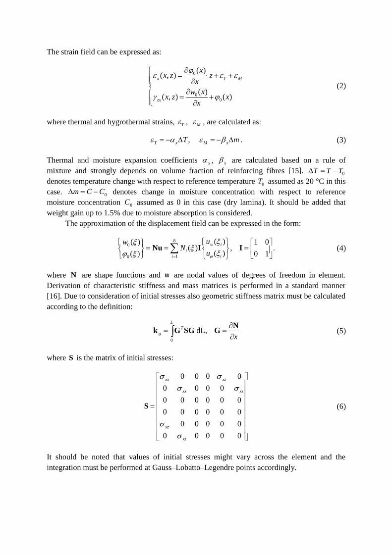
Scheme of the beam under investigation is shown in Fig. 2. The beam is subjected to
static load F applied at the left end, various uniform changes in temperature T as well as in
moisture concentration m . The beam is excited in the centre by sinusoidal signal modulated
by Hanning window. Various carrier frequencies between 20 kHz and 48 kHz were used.
It was assumed that the beam is made out of glass/epoxy composite with stacking
sequence [+45/–45]6 and 50% of volume fraction of glass reinforcing fibres. The width of the
beam was 20 mm, and the total thickness was 12 mm. Crack depth equal to 15% of cross–
section height was introduced at distance of 0.73 m from the left end of the beam. The total
length of the beam was 1 m.
Figure 2. Scheme of the beam under investigation.
Properties of glass/epoxy lamina under various moisture concentrations and various
temperatures are given in Table 1 and Table 2, respectively.
Table 1. Elastic moduli of glass/epoxy lamina at various moisture concentrations assumed for
calculations, vol=50%
Elastic modulus
[GPa]
Moisture concentration, C (%)
0.00 0.25 0.50 0.75 1.00 1.25 1.50
1E 34.96 34.92 34.87 34.83 34.80 34.78 34.78
2E 9.06 8.87 8.63 8.41 8.26 8.19 8.19
12G 3.39 3.32 3.23 3.14 3.09 3.06 3.06
Table 1. Elastic moduli of glass/epoxy lamina at various temperatures assumed for
calculations, vol=50%
Elastic modulus
[GPa]
Temperature, T (°C)
20 25 30 35 40 45 50
1E 34.96 34.94 34.92 34.90 34.85 34.77 34.65
2E 9.06 8.93 8.85 8.74 8.54 8.16 7.56
12G 3.39 3.34 3.31 3.27 3.19 3.05 2.82
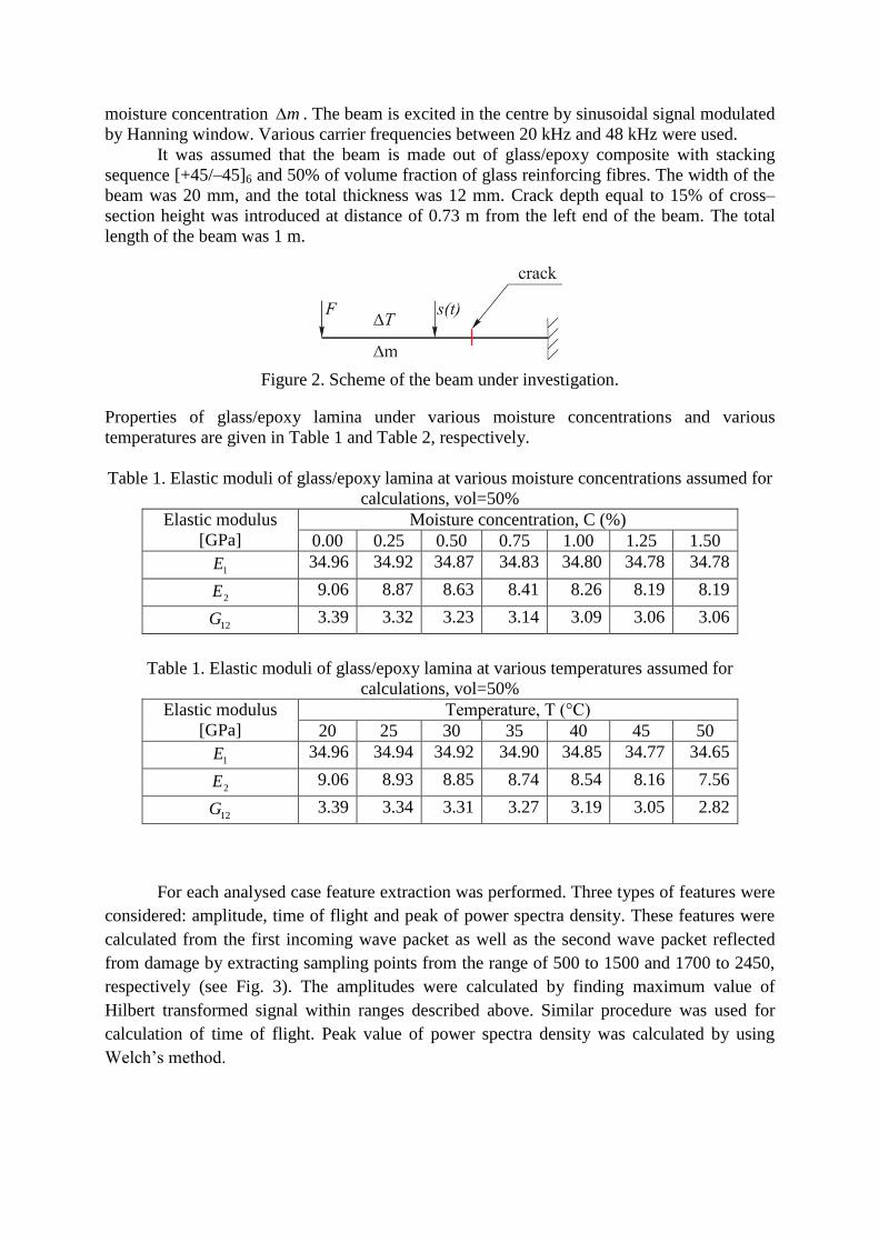
For each analysed case feature extraction was performed. Three types of features were
considered: amplitude, time of flight and peak of power spectra density. These features were
calculated from the first incoming wave packet as well as the second wave packet reflected
from damage by extracting sampling points from the range of 500 to 1500 and 1700 to 2450,
respectively (see Fig. 3). The amplitudes were calculated by finding maximum value of
Hilbert transformed signal within ranges described above. Similar procedure was used for
calculation of time of flight. Peak value of power spectra density was calculated by using
Welch’s method.
Figure 3. Signal for excitation frequency 20 kHz with indicated wave packets under investigation:
incoming wave packet and reflection from the crack
The results of numerical simulations are shown in Fig. 4–6. Figure 4 refers to thermal
degradation exclusively. Due to free boundary condition at one of the ends of the beam along
with uniform temperature distribution only thermal expansion occurs without any induced
thermal stresses. Thermal expansion has minimal effect on wave propagation in comparison
to thermal degradation (decrease of the Young’s modulus of the epoxy) and is not shown
here. It can be seen from Fig. 4 that features dependence on frequency and temperature
change is strongly nonlinear. It is interesting to note that by comparing left and right columns
of Fig. 4a it is possible to distinguish between incoming wave packet and wave packet
reflected from the crack. The same can be said about Fig. 4c which refers to the peak of
power spectra density. Time of flight distribution is similar for both wave packets.
Similar effects can be observed due to moisture degradation. Again moisture
expansion and mass gain due to moisture absorption much less affects wave propagation than
moisture degradation. For this reason only the effect of moisture degradation is shown in Fig.
5. Due to the fact that moisture degradation acts similar as thermal degradation on
propagating waves it would be very difficult to separate those two effects.
The influence of transverse load applied on the free end of the beam on wave
propagation is much less noticeable than the effects of moisture and temperature (see Fig. 6).
It should be pointed out that the selected range of loading conforms to reasonable physical
case. It is also important to add that calculations have been carried out on undeformed
structure. In such a case both amplitude (Fig. 6a) and time of flight (Fig. 6b) are slightly
affected by external loading in a linear manner.

a) Amplitude
b) Time of Flight (TOF)
c) Power Spectra Density Peak (PSDP)
Figure 4. Dependence of features on temperature change (thermal degradation). Left column –
features for the incoming wave packet, right column – features for the wave packet reflected
from the crack.

a) Amplitude
b) Time of Flight (TOF)
c) Power Spectra Density Peak (PSDP)
Figure 5. Dependence of features on moisture (moisture degradation). Left column – features
for the incoming wave packet, right column – features for the wave packet reflected from the
crack.
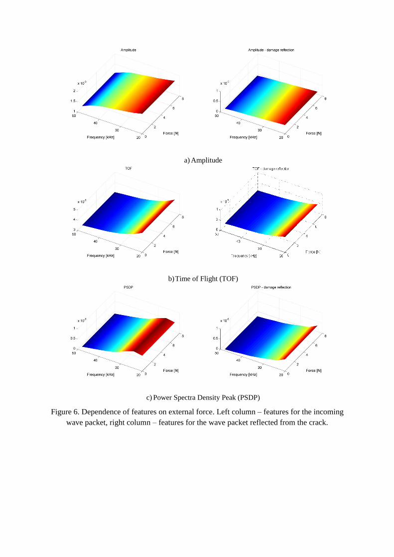
a) Amplitude
b) Time of Flight (TOF)
c) Power Spectra Density Peak (PSDP)
Figure 6. Dependence of features on external force. Left column – features for the incoming
wave packet, right column – features for the wave packet reflected from the crack.

4. CONCLUSIONS
Algorithm for solving wave propagation problems in composite Timoshenko beams
has been developed. It incorporates many effects such as external loading, temperature change
and moisture degradation as well as transverse crack. Several features of propagating waves
has been analysed in order to find distinction between these effects. It can be concluded that
in order to estimate crack depth properly it is necessary to compensate effects of temperature
and moisture change in composite structure. Wave propagation is also affected by external
loading but in the case considered the loading effect has much less importance than thermal
and hygrothermal degradation. Features analysis performed would be used in future for
selection of input features for damage identification methods based on machine learning
algorithms.
Acknowledgements
Pawel Kudela would like to gratefully acknowledge the Foundation for Polish Science
for the support in his research in the frame of KOLUMB scholarship.
Wieslaw Ostachowicz would like to gratefully acknowledge the support provided by
project MONIT – Monitoring of technical state of construction and evaluation of its lifespan
(ref. no. POIG.01.01.02–00–013/08).
5. REFERENCES
[1] Blaise E., F.K. Chang, “Built–in diagnostics for debonding in sandwich structures under
extreme temperatures”. Proceedings of the 3rd International Workshop on SHM, 154–
163, Stanford, California, USA, 2001.
[2] Lu Y., Michaels J.E., “A methodology for structural health monitoring with diffuse
ultrasonic waves in the presence of temperature variations”. Ultrasonics. 43, 717–731,
2005.
[3] Konstantinidis G., Wilcox P.D., Drinkwater B.W. „An Investigation Into the Temperature
Stability of a Guided Wave Structural Health Monitoring System Using Permanently
Attached Sensors”. IEEE Sens. J. 7(5), 905–912, 2007.
[4] Roy S., Lonkar, K., Janapati, V., Chang, F.–K., "Physics Based Temperature
Compensation Strategy for Structural Health Monitoring". Proceedings of the 8th
International Workshop on SHM, Stanford University, USA, 1, 1139–1149, 2011.
[5] Ha S., Lonkar, K., Mittal, A., Chang, F.–K., "Adhesive Layer Effects on PZT–induced
Lamb Waves at Elevated Temperatures". SHM J., 26, 247–256, 2010.
[6] Kudela P., Ostachowicz W., Zak A., “Influence of temperature fields on wave propagation
in composite plates”. Key Engineering Materials, 347, 537–542, 2007.
[7] Vinson J.R., Sierakowski R.L., “Behaviour of Structures Composed of Composite
Materials”, Martinus Nijhoff, Dorchester, 1989.
[8] Abdel–Magdid B., Ziaee S., Gass K., Schneider M.,“The combined effects of load,
moisture and temperature on the properties of E–glass/epoxy composites”. Compos.
Struct., 71, 320–326, 2005.
[9] Tsai Ch.L., Wang Ch.H., Chang J.–J., Yeih W., “Tracking hygrothermal strains of

carbon/epoxy composite under varying temperature and humidity”. J Compos. Mater.
42(16), 1597–1618, 2008.
[10] Sai Ram K.S., Sinha P.K, “Hygrothermal effects on the free vibration of laminated
composite plates”, J. Sound Vib., 158(1), 133–148, 1992.
[11] Chen F., Wilcox P. D., "The effect of load on guided wave propagation". Ultrasonics,
47(1–4), 645–649, 2007.
[12] Hayashi T., Song W.–J., Rose J. L., “Guided wave dispersion curves for a bar with an
arbitrary cross–section, a rod and rail example”. Ultrasonics, 41, 175–183, 2003.
[13] Lematre M., Feuillard G., Clézio E. L., Lethiecq M., "Modeling of the influence of a
prestress gradient on guided wave propagation in piezoelectric structures". J Acoust. Soc.
Am., 120(4), 1964–1975, 2006.
[14] Chakraborty A., “The effect of surface stress on the propagation of Lamb waves”.
Ultrasonics, 50, 645–649, 2010.
[15] Karadeniz Z.H., Kumlutas D., “A numerical study on the coefficients of thermal
expansion of fibre reinforced composite materials”. Compos. Struct. 78, 1–10, 2007.
[16] Ostachowicz W, Kudela P., Krawczuk M., Żak A. ,“Guided Waves in Structures for
SHM: The Time–domain Spectral Element Method”, Wiley, 2012.
[17] Tada H., Paris P.C., Irwin G.R., “The Stress Analysis of Cracks Handbook”, Del
Research Corporation, Hellertown, PA, 1973.