
A/360, ATSC 3.0 Security and Service Protection · PDF fileElectrical and Electronic Engineers...
33
ATSC A/360:2018 ATSC 3.0 Security and Service Protection 9 January 2018 i ATSC Standard: ATSC 3.0 Security and Service Protection Doc. A/360:2018 9 January 2018 Advanced Television Systems Committee 1776 K Street, N.W. Washington, D.C. 20006 202-872-9160
Transcript of A/360, ATSC 3.0 Security and Service Protection · PDF fileElectrical and Electronic Engineers...

ATSC A/360:2018 ATSC 3.0 Security and Service Protection 9 January 2018
i
ATSC Standard: ATSC 3.0 Security and Service Protection
Doc. A/360:2018 9 January 2018
Advanced Television Systems Committee 1776 K Street, N.W. Washington, D.C. 20006 202-872-9160

ATSC A/360:2018 ATSC 3.0 Security and Service Protection 9 January 2018
ii
The Advanced Television Systems Committee, Inc., is an international, non-profit organization developing voluntary standards for digital television. The ATSC member organizations represent the broadcast, broadcast equipment, motion picture, consumer electronics, computer, cable, satellite, and semiconductor industries.
Specifically, ATSC is working to coordinate television standards among different communications media focusing on digital television, interactive systems, and broadband multimedia communications. ATSC is also developing digital television implementation strategies and presenting educational seminars on the ATSC standards.
ATSC was formed in 1982 by the member organizations of the Joint Committee on InterSociety Coordination (JCIC): the Electronic Industries Association (EIA), the Institute of Electrical and Electronic Engineers (IEEE), the National Association of Broadcasters (NAB), the National Cable Telecommunications Association (NCTA), and the Society of Motion Picture and Television Engineers (SMPTE). Currently, there are approximately 150 members representing the broadcast, broadcast equipment, motion picture, consumer electronics, computer, cable, satellite, and semiconductor industries.
ATSC Digital TV Standards include digital high definition television (HDTV), standard definition television (SDTV), data broadcasting, multichannel surround-sound audio, and satellite direct-to-home broadcasting.
Note: The user's attention is called to the possibility that compliance with this standard may require use of an invention covered by patent rights. By publication of this standard, no position is taken with respect to the validity of this claim or of any patent rights in connection therewith. One or more patent holders have, however, filed a statement regarding the terms on which such patent holder(s) may be willing to grant a license under these rights to individuals or entities desiring to obtain such a license. Details may be obtained from the ATSC Secretary and the patent holder.
Revision History Version Date Candidate Standard approved 28 October 2016 Revision 1 approved 27 March 2017 Standard approved 9 January 2018

ATSC A/360:2018 ATSC 3.0 Security and Service Protection 9 January 2018
iii
Table of Contents 1. SCOPE ..................................................................................................................................................... 1
1.1 Organization 1 2. REFERENCES ......................................................................................................................................... 1
2.1 Normative References 1 2.2 Informative References 3
3. DEFINITION OF TERMS .......................................................................................................................... 3 3.1 Compliance Notation 3 3.2 Treatment of Syntactic Elements 4
3.2.1 Reserved Elements 4 3.3 Acronyms and Abbreviation 4 3.4 Terms 4
4. SYSTEM OVERVIEW ............................................................................................................................... 5 4.1 Features 5 4.2 System Architecture 5 4.3 Central Concepts 5
5. SPECIFICATION ...................................................................................................................................... 6 5.1 Transport Protection 6
5.1.1 Internet Streaming Transport Security 6 5.2 ATSC 3.0 Cryptographic Signing 9
5.2.1 ATSC 3.0 Application Code Signing 9 5.2.2 ATSC 3.0 Signaling Message Signing 10
5.3 Certificates and Certificate Management 14 5.3.1 Certificate Profiles 15
5.4 ATSC 3.0 Client Certificate Storage 16 5.5 Certificate Revocation and Status Information 16
5.5.1 Certificate Revocation and Status Information for TLS Server Certificates 16 5.5.2 Certificate Revocation and Status Information for ATSC 3.0 Application
Signing Certificates 17 5.6 Pre-Shared Key Encrypted Connections 17
5.6.1 Pre-shared Key Registration 17 5.6.2 TLS 1.3 Pre-Shared Key Exchange Parameters 18
5.7 Content Protection 19 5.7.1 Common Encryption 19 5.7.2 Encrypted Media Extensions 20 5.7.3 CENC and EME Support 22
5.8 Backend Business Systems 22 5.9 DRM License and Key Delivery for Broadcast-Only Devices 22
ANNEX A: ROUTE/DASH CLIENT PROCESSING FOR COMMON ENCRYPTION (CENC) AND ENCRYPTED MEDIA EXTENSIONS (EME) (INFORMATIVE) .............................................................. 23 A.1 Introduction 23
A.1.1 Basic CENC Operation in ROUTE/DASH 23 A.1.2 Solution Framework for DRM and CENC 25 A.1.3 MPD Support for Encryption and DRM Signaling 28

ATSC A/360:2018 ATSC 3.0 Security and Service Protection 9 January 2018
iv
Index of Figures and Tables Figure 5.1 Storage of CENC related information. 20 Figure 5.2 Encrypted Media Extensions workflow. 21 Figure A.1 DRM license and key acquisition before start of program in ROUTE/DASH. 24 Figure A.2 DRM license and key acquisition during program delivery in ROUTE/DASH. 25 Figure A.3 CENC-related metadata structure for protection of VoD content by a
single key. 27 Figure A.4 CENC-related metadata structure for protection of live streaming content. 27

ATSC A/360:2018 ATSC 3.0 Security and Service Protection 9 January 2018
1
ATSC Standard: ATSC 3.0 Security and Service Protection
1. SCOPE This standard specifies the mechanisms for security and service protections in ATSC 3.0 systems.
1.1 Organization This document is organized as follows:
• Section 1 – Outlines the scope of this document and provides a general introduction. • Section 2 – Lists references and applicable documents. • Section 3 – Provides a definition of terms, acronyms, and abbreviations for this document. • Section 4 – System overview • Section 5 – Specification • Annex A – ROUTE/DASH Client Processing for CENC and EME
2. REFERENCES All referenced documents are subject to revision. Users of this Standard are cautioned that newer editions might or might not be compatible.
2.1 Normative References The following documents, in whole or in part, as referenced in this document, contain specific provisions that are to be followed strictly in order to implement a provision of this Standard. [1] IEEE: “Use of the International Systems of Units (SI): The Modern Metric System,” Doc. SI
10, Institute of Electrical and Electronics Engineers, New York, N.Y. [2] ISO/IEC: ISO/IEC 23001-7 Second edition 2015-04-01, “Information technology — MPEG
systems technologies — Part 17: Common encryption in ISO base media file format files.” [3] W3C: “Encrypted Media Extensions,” W3C Recommendation 18 September 2017, World
Wide Web Consortium, https://w3c.github.io/encrypted-media/. [4] W3C: “Media Source Extensions”, W3C Recommendation 17 November 2016, World Wide
Web Consortium, https://w3c.github.io/media-source/. [5] DASH: “Guidelines for Implementation: DASH-IF Interoperability Points for ATSC 3.0”,
Version 1.0, DASH Industry Forum, Beaverton, OR, 31 January 2017. [6] IETF: “RFC 3279, Algorithms and Identifiers for the Internet X.509 Public Key
Infrastructure Certificate and Certificate Revocation List (CRL) Profile,” L. Bassham, W. Polk, R. Housley, Internet Engineering Task Force, Fremont, CA, April 2002.
[7] IETF: “RFC 4033, DNS Security Introduction and Requirements,” Arends, R., Austein, R., Larson, M., Massey, D., and S. Rose, Internet Engineering Task Force, Fremont, CA, March 2005.
[8] IETF: “RFC 4055, Additional Algorithms and Identifiers for RSA Cryptography forw use in the Internet X.509 Public Key Infrastructure Certificate and Certificate Revocation List (CRL) Profile,” J. Schaad, B. Kaliski, R. Housley, Internet Engineering Task Force, Fremont, CA, June 2005.

ATSC A/360:2018 ATSC 3.0 Security and Service Protection 9 January 2018
2
[9] IETF: “RFC 5019, The Lightweight Online Certificate Status Protocol (OCSP) Profile for High-Volume Environments,” A. Deacon, R. Hurst, Internet Engineering Task Force, Fremont, CA, September 2007.
[10] IETF: “RFC 5077, Transport Layer Security (TLS) Session Resumption without Server-Side State,” J. Salowey, H. Zhou, P. Eronen, H. Tschofenig, Internet Engineering Task Force, Fremont, CA, January 2008.
[11] IETF: “RFC 5246, The Transport Layer Security (TLS) Protocol Version 1.2,” T. Dierks, E. Rescorla, Internet Engineering Task Force, Fremont, CA, August 2008.
[12] IETF: “RFC 5280, Internet X.509 Public Key Infrastructure Certificate and Certificate Revocation List (CRL) Profile,” D. Cooper, S. Santesson, S. Farrell, S. Boeyen, R. Housley, W. Polk, Internet Engineering Task Force, Fremont, CA, May 2008.
[13] IETF: “RFC 5289, TLS Elliptic Curve Cipher Suites with SHA-256/384 and AES Galois Counter Mode (GCM),” E. Rescorla, Internet Engineering Task Force, Fremont, CA, August 2008.
[14] IETF: “RFC 5480, Elliptic Curve Cryptography Subject Public Key Information,” S. Turner, D. Brown, K. Yiu, R. Housley, T. Polk, Internet Engineering Task Force, Fremont, CA, March 2009.
[15] IETF: “RFC 5652, Cryptographic Message Syntax (CMS),” R. Housley, Internet Engineering Task Force, Fremont, CA, September 2009.
[16] IETF: “RFC 5746, Transport Layer Security (TLS) Renegotiation Indication Extension,” E. Rescorla, M. Ray, S. Dispensa, N. Oskov, Internet Engineering Task Force, Fremont, CA, February 2010.
[17] IETF “RFC 5751 Secure/Multipurpose Internet Mail Extensions (S/MIME) Version 3.Message Specification,” B. Ramsdell, S. Turner, Internet Engineering Task Force, Fremont, CA, January 2010.
[18] IETF: “RFC 5753 Use of Elliptic Curve Cryptography (ECC) Algorithms in Cryptographic Message Syntax (CMS),” S. Turner, D. Brown, Internet Engineering Task Force, Fremont, CA, January 2010.
[19] IETF: “RFC 5758, Internet X.509 Public Key Infrastructure: Additional Algorithms and Identifiers for DSA and ECDSA,” Q. Dang, S. Santesson, K. Moriarty, D. Brown, T. Polk, Internet Engineering Task Force, Fremont, CA, January 2010.
[20] IETF: “RFC 5869, HMAC-based Extract-and-Expand Key Derivation Function (HKDF),” H. Krawczyk, P. Eronen, Internet Engineering Task Force, Fremont, CA, May 2010.
[21] IETF: “RFC 5940: Additional Cryptographic Message Syntax (CMS) Revocation Information Choices,” S. Turner, R. Housley, Internet Engineering Task Force, Fremont, CA, August 2010.
[22] IETF: “RFC 6066, Transport Layer Security (TLS) Extensions: Extension Definitions,” D. Eastlake 3rd, Internet Engineering Task Force, Fremont, CA, January 2011.
[23] IETF: “RFC 6840, Clarifications and Implementation Notes for DNS Security (DNSSEC)", S. Weiler, and D. Blacka, Internet Engineering Task Force, Fremont, CA, February 2013.
[24] IETF: “RFC 6960, X.509 Internet Public Key Infrastructure Online Certificate Status Protocol – OCSP,” S. Santesson, M. Myers, R. Ankney, A. Malpani, S. Galperin, C. Adams, Internet Engineering Task Force, Fremont, CA, June 2013.

ATSC A/360:2018 ATSC 3.0 Security and Service Protection 9 January 2018
3
[25] IETF: “RFC 8018, PKCS #5: Password-Based Cryptography Specification, Version 2.1,” K. Moriarty, B. Kaliski, A. Rusch, Internet Engineering Task Force, Fremont, CA, January 2017.
[26] IETF: “TLS 1.3, The Transport Layer Security (TLS) Protocol Version 1.3,” draft-ietf-tls-tls13-22, Internet Engineering Task Force, Fremont, CA.
[27] IETF: “RFC 7539, ChaCha20 and Poly1305 for IETF Protocols,” Y. Nir, A. Langley, Internet Engineering Task Force, Fremont, CA, May 2015.
[28] ITU-T: “Information technology – Open Systems Interconnection – Procedures for the operation of OSI Registration Authorities: Generation and registration of Universally Unique Identifiers (UUIDs) and their use as ASN.1 object identifier components”, Rec. X.667, International Telecommunication Union, September 2004.
2.2 Informative References The following documents contain information that may be helpful in applying this Standard. [29] CTA: “CEA 2053. Receiver Specifications for ATSC 2.0 Security,” ANSI/CTA-2053,
Consumer Technology Association, Arlington, VA, August 2015. [30] ATSC: “ATSC Standard: Companion Device (A/338),” Doc. A/338:2017, Advanced
Television System Committee, Washington, D.C., 17 April 2017. [31] ATSC: “ATSC Standard: Signaling, Delivery, Synchronization and Error Protection,” Doc.
A/331:2017, Advanced Television System Committee, Washington, D.C., 6 December 2017. [32] ISO/IEC: “ISO/IEC 23009–1:2014, Information technology — Dynamic adaptive streaming
over HTTP (DASH) — Part 1: Media presentation description and segment formats,” International Organization for Standardization, Geneva, 2nd Edition, 15 May 2014.
[33] DASH: “Guidelines for Implementation: DASH-IF Interoperability Points”, Version 4.0, DASH Industry Forum, Beaverton, OR, 12 December 2016.
[34] ISO/IEC: “Information technology – High efficiency coding and media delivery in heterogeneous environments – Part 1: MPEG media transport (MMT),” Doc. ISO/IEC 23008-1:2017(E), International Organization for Standardization/ International Electrotechnical Commission, Geneva Switzerland.
3. DEFINITION OF TERMS With respect to definition of terms, abbreviations, and units, the practice of the Institute of Electrical and Electronics Engineers (IEEE) as outlined in the Institute’s published standards [1] shall be used. Where an abbreviation is not covered by IEEE practice or industry practice differs from IEEE practice, the abbreviation in question will be described in Section 3.3 of this document.
3.1 Compliance Notation This section defines compliance terms for use by this document: shall – This word indicates specific provisions that are to be followed strictly (no deviation is
permitted). shall not – This phrase indicates specific provisions that are absolutely prohibited. should – This word indicates that a certain course of action is preferred but not necessarily
required. should not – This phrase means a certain possibility or course of action is undesirable but not
prohibited.

ATSC A/360:2018 ATSC 3.0 Security and Service Protection 9 January 2018
4
3.2 Treatment of Syntactic Elements This document contains symbolic references to syntactic elements used in the audio, video, and transport coding subsystems. These references are typographically distinguished by the use of a different font (e.g., restricted), may contain the underscore character (e.g., sequence_end_code) and may consist of character strings that are not English words (e.g., dynrng). 3.2.1 Reserved Elements One or more reserved bits, symbols, fields, or ranges of values (i.e., elements) may be present in this document. These are used primarily to enable adding new values to a syntactical structure without altering its syntax or causing a problem with backwards compatibility, but they also can be used for other reasons.
The ATSC default value for reserved bits is ‘1.’ There is no default value for other reserved elements. Use of reserved elements except as defined in ATSC Standards or by an industry standards-setting body is not permitted. See individual element semantics for mandatory settings and any additional use constraints. As currently-reserved elements may be assigned values and meanings in future versions of this Standard, receiving devices built to this version are expected to ignore all values appearing in currently-reserved elements to avoid possible future failure to function as intended.
3.3 Acronyms and Abbreviation The following acronyms and abbreviations are used within this document. AES – Advanced Encryption Standard ATSC – Advanced Television Systems Committee CA – Certificate Authority CEA – Consumer Electronics Association DNS – Domain Name System DTCP – Digital Transmission Content Protection ECDHE – Elliptic Curve Diffie-Hellman Ephemeral key exchange ECDSA – Elliptic Curve Digital Signature Algorithm GCM – Galois Counter Method IP – Internet Protocol OCSP – Online Certificate Status Protocol RSA – A method for obtaining digital signatures and public-key cryptosystems (originally
proposed by Rivest, Shamir, and Adelman). SECP – Standard for Efficient Cryptography Elliptic Curve Domain Parameters SHA – Secure Hash Algorithm TLS – Transport Layer Security UUID – Universally Unique Identifier
3.4 Terms The following terms are used within this document. ATSC 3.0 Server – Any IP-connected device that provides content or other service to an ATSC
3.0 client, and that complies with the normative requirements of this standard.

ATSC A/360:2018 ATSC 3.0 Security and Service Protection 9 January 2018
5
Author Signature – A signature encoded in the form specified in Section 5.2 below that is generated by the author of the application, which is the entity or entities whom claim authorship over the application content.
Distributor Signature – A signature encoded in the form specified in Section 5.2 below that is generated by a distributor, which is a third party (e.g., the broadcaster) that is distributing the application on behalf of the author.
Privileged Application – An application that can override system controls, authorizations, or privileges.
reserved – Set aside for future use by a Standard.
4. SYSTEM OVERVIEW
4.1 Features This specification defines a set of methods designed to secure the following content and data flows described in other ATSC 3.0 specifications:
1) Content protection for MPEG-DASH content delivery (Section 5.7) 2) Authentication of ATSC 3.0 applications (Section 5.2) 3) Authentication of ATSC 3.0 Broadcast Signaling (Section 5.3) 4) Interactive data exchanged over an internet connection between an ATSC 3.0 application
and a web content server (Section 5.1), including the use of DNS Security (Section 5.1.1.7) 5) Data flows between an ATSC 3.0 primary device and a companion device (Section 5.6)
4.2 System Architecture This specification defines a number of profiles for established security specifications defined by IETF, ISO and W3C. In defining these profiles, this specification seeks to establish a consistent use of cryptographic algorithms across the different content and data flows that it addresses. The profiles are designed to provide some degree of flexibility in the choice of cryptographic algorithms being used in a particular flow while enabling the use of commonly available implementations of the specified standard technologies.
In the case of MPEG-DASH content protection, this specification defines the use of common encryption techniques that allow content protection licences to be delivered to a number of different content decryption modules from different suppliers.
4.3 Central Concepts Several of the specifications referenced herein make use of a chain of trust based on the provisioning of X.509 certificates in the message flow and the establishment of a set of trust anchors within the ATSC 3.0 receiver (Sections 5.2.2 and 5.4). In addition to the concept of the chain of trust, this specification also defines the carriage of certificate revocation information in On-line Certificate Status Response (OCSP) constructs in order to verify the validity of the certificates in the chain of trust (Section 5.5). The carriage of these constructs within the message flow avoids each ATSC 3.0 receiver separately requesting this information thus avoiding unnecessary traffic flow peaks to the OCSP responder.

ATSC A/360:2018 ATSC 3.0 Security and Service Protection 9 January 2018
6
5. SPECIFICATION
5.1 Transport Protection Transport Protection provides protection against spoofing or hijacking the delivery of the data. This may include protection of content that is not separately encrypted. Encryption of content in transit will be described in this section. 5.1.1 Internet Streaming Transport Security
5.1.1.1 TLS – Transport Layer Security ATSC 3.0 clients are expected to implement both TLS 1.3 [26] and TLS 1.2 (RFC 5246 [11]) for Secure Connections over the Interaction Channel. An ATSC 3.0 client is expected to request a connection using TLS 1.3 (ProtocolVersion { 0x03, 0x04 }), but is also expected to accept a server’s request to downgrade the connection to TLS 1.2 (ProtocolVersion { 0x03, 0x03 }) in the manner specified in TLS 1.3 Appendix C.
An ATSC 3.0 server, when negotiating a Secure Connection for use with ATSC 3.0 Interaction Channel protocols should comply with TLS 1.3. An ATSC 3.0 server that does not support TLS 1.3 shall respond with a “Server Hello” message specifying a ProtocolVersion { 0x03, 0x03 } (indicating TLS 1.2). The server shall refuse Secure Connection negotiations with clients that do not support a ProtocolVersion equal to or greater than { 0x03, 0x03 } and shall send a protocol_version alert message to the client as described in TLS 1.3 Appendix C (TLS 1.2 Appendix E). 5.1.1.2 TLS 1.3 Server Connection Negotiation An ATSC 3.0 server that supports TLS 1.3 shall only negotiate Secure Connections using one or more combinations of a Cipher Suite, Elliptic Curve Group and Signature Algorithm as specified in Sections 5.1.1.2.1, 5.1.1.2.2 and 5.1.1.2.3 respectively.
ATSC 3.0 servers that support TLS 1.3 shall decline to establish a connection that does not request at least one combination of these Signature Algorithms, Elliptic Curve Groups, and Cipher Suites.
ATSC 3.0 clients that support TLS 1.3 are expected to only negotiate Signature Algorithms, Elliptic Curve Groups, and Cipher Suites identified in this section.
Cipher Suites TLS_AES_128_GCM_SHA256
TLS_AES_256_GCM_SHA384
TLS_CHACHA20_POLY1305_GCM_SHA256
(as specified in TLS 1.3 [26]). Elliptic Curve Groups
secp256r1
secp384r1
secp521r1
(as specified in TLS 1.3 [26]). Each elliptic curve group shall be used with the uncompressed point format.

ATSC A/360:2018 ATSC 3.0 Security and Service Protection 9 January 2018
7
Signature Algorithms rsa_pkcs1_sha256
rsa_pkcs1_sha384
rsa_pkcs1_sha512
ecdsa_secp256r1_sha256
ecdsa_secp384r1_sha384
ecdsa_secp521r1_sha512
rsa_pss_sha256
rsa_pss_sha384
rsa_pss_sha512
(as specified in TLS 1.3 [26]). 5.1.1.3 TLS 1.2 Server Connection Negotiation ATSC 3.0 servers that only support TLS 1.2 shall negotiate Secure Connections using one or more of the following Cipher Suites (as specified in RFC 5289 [13]):
TLS_ECDHE_ECDSA_WITH_AES_128_GCM_SHA256
TLS_ECDHE_ECDSA_WITH_AES_256_GCM_SHA384
TLS_ECDHE_RSA_WITH_AES_128_GCM_SHA256
TLS_ECDHE_RSA_WITH_AES_256_GCM_SHA384
or one or more of the following Cipher Suites (as specified in RFC 7539 [27]) where these cipher suites are requested by the client:
TLS_ECDHE_ECDSA_WITH_CHACHA20_POLY1305_SHA256
TLS_RSA_ECDSA_WITH_CHACHA20_POLY1305_SHA256
or
TLS_RSA_WITH_AES_128_CBC_SHA
(as specified in RFC 5246 [11]) may be negotiated for, however, the server shall only choose this Cipher Suite as the least preferred of the client’s cipher suites (irrespective of the order supplied by the client).
Elliptic Curve Groups An ATSC 3.0 server shall support the following Elliptic Curve Groups: secp256r1, secp384r1, and secp521r1. An ATSC 3.0 server shall support the uncompressed point format.
Servers shall decline to establish a connection that does not request one or more of these curve groups or point formats.
The client is expected to only negotiate elliptic curve groups and point formats that are required to be supported by an ATSC 3.0 server.
Signature Algorithms An ATSC 3.0 server shall support the rsa or ecdsa Signature Algorithm with any of sha256, sha384 or sha512 Hash Algorithm.
An ATSC 3.0 client that is negotiating (or renegotiating) a TLS 1.2 connection may request one of these Signature Algorithm and Hash Algorithm combinations or may omit the Signature

ATSC A/360:2018 ATSC 3.0 Security and Service Protection 9 January 2018
8
Algorithm Extension. When a client does not include a Signature Algorithm Extension, the ATSC 3.0 server shall reject the connection request with an insufficient_security error. 5.1.1.4 Server Certificate Selection An ATSC 3.0 server shall only supply certificates with signatures using one of the supported signature and hash algorithm combinations (see Sections 5.1.1.3.2 above) that is negotiated by the client (even in the case that the client attempts to negotiate other algorithms) and shall not establish a Secure Connection with certificates that use other algorithms.
When a client requests a connection over TLS 1.2 or TLS 1.3 it is expected to include a Server Name Indication extension as specified in RFC 6066 [22]that contains the fully qualified DNS host name of the server. The ATSC 3.0 server shall use the Server Name Indication provided by the client to assist in the selection of a suitable server certificate to return to the client in the TLS handshake.
When a client requests a connection over TLS 1.3 it can include a Certificate Authorities extension as specified in TLS 1.3 [26] to provide a list of the trusted root certificates that it holds in its secure store. When a client requests a connection over TLS 1.2 it can include a Trusted CA Indication extension as specified in RFC 6066 [22] to provide a list of the trusted root certificates that it holds in its secure store. Receiver manufacturers choose the set of trusted root certificates. The ATSC 3.0 server shall use the Trusted CA Indication extension to assist in the selection of a suitable certificate chain to return to the client in the TLS handshake.
In the case that an ATSC 3.0 server is unable to select a certificate chain that matches the client criteria in either the Server Name Indication extension or the Trusted CA Indication extension, the ATSC 3.0 server shall not establish the connection. 5.1.1.5 TLS Certificate Status Request and Response The client is expected to include the Certificate Status Request extension as specified in RFC 6066 [22] Section 8. The Certificate Status Request extension includes a list of OCSP Responder Identifiers each encoded as a SHA-1 hash of the trusted OCSP responder public key as defined in RFC 6960 [23]. An ATSC 3.0 server shall only supply to the client the OCSP responses that it has received from OCSP responders with responder public keys that are trusted by the client and which are signed using signature algorithms supported by the client. If an ATSC 3.0 server is unable to obtain an OCSP Response for a certificate that it supplies from an OCSP Responder that is identified by the client as a trusted responder, the ATSC 3.0 server shall not establish the connection.
The ATSC 3.0 server shall forward the most recent OCSP Response (see Section 5.5.1 below) for the certificates it uses to establish a connection to the ATSC 3.0 client. The format of the OCSP Response provided by the responder should be limited to the mandatory elements defined in RFC 5019 [9] and no optional elements should be included in the response. When a server is establishing a connection over TLS 1.2, the server shall include the OCSP Response in its Certificate Status handshake message (immediately after its Certificate handshake message) as defined in RFC 6960 [23]. When a server is establishing a connection over TLS 1.3, the server shall include the OCSP Response in the Certificate message.
The ATSC 3.0 client is expected to verify the Certificate Status message provided by the server as specified in RFC 6066 [22] Section 8. A client uses the OCSP Response data that it receives to verify that the certificates that authenticate server connections are valid at the time the connection is established. See CEA 2053 [29].

ATSC A/360:2018 ATSC 3.0 Security and Service Protection 9 January 2018
9
5.1.1.6 TLS Session Resumption An ATSC 3.0 server that has a newly established TLS 1.3 connection may provide a New Session Ticket message once it has received the client’s Finished handshake message. The New Session Ticket message shall not include the Early Data Indication extension. A client may supply the information from this session ticket in the pre_shared_key extension in a subsequent Client Hello message to resume the TLS session. The client is expected to negotiate session resumption using the same elliptic curve group and cipher suite and Server Name Indication extension as used when the original connection was established. The client is expected to set the Pre-Shared Key Exchange Mode set to psk_dhe_ek which will enable a new ephemeral ECDHE key to be established.
On receipt of a session resumption Client Hello the ATSC 3.0 server shall verify that the session ticket is still valid and that the client has selected the same elliptic curve group and cipher suite as used for the original connection. The server shall also verify that the Server Name Indication extension supplied in the Client Hello message is the same as that provided for the original connection. The server shall only negotiate a session resumption request that includes a Pre-Shared Key Exchange Mode set to psk_dhe_ek. The ATSC 3.0 server shall not respond to a Client Hello message that contains early_data thus requiring the client to issue a session resumption Client Hello message without any early data.
An ATSC 3.0 server that has established a TLS 1.2 connection session may support the Session Ticket Extension (RFC 5077 [10]) to allow later resumption of that session. If the ATSC 3.0 server does not support this extension, then it shall not send an empty Session Ticket Extension to the client that has requested session ticket information.
TLS Connection Renegotiation TLS 1.3 does not support connection renegotiation.
An ATSC 3.0 client that is processing a TLS 1.2 handshake is expected to support the Renegotiation Indication extension (RFC 5746 [16]) but is not expected to send a Client Hello handshake message that includes any data in this extension. An ATSC 3.0 server that is processing a TLS 1.2 handshake shall include an empty Renegotiation Indication extension as required by RFC 5746 [16] in the Server Hello message to indicate that it does not support renegotiation. An ATSC 3.0 server that is processing a TLS 1.2 handshake shall not send a Hello Request message to the client to instigate renegotiation of connection parameters. 5.1.1.7 DNSSEC – Domain Name System Security Extensions An ATSC 3.0 server shall be a member of a DNSSEC signed zone as described in RFC 6840[23] and RFC 4033[7]. This specification expects that an ATSC 3.0 receiver implements a DNSSEC Security-Aware Stub Resolver as specified in RFC 4033[7].
5.2 ATSC 3.0 Cryptographic Signing This standard includes mechanisms below for cryptographically signing applications and signaling. Implementation of these features requires one or several Public Key Infrastructure(s) (PKI) that are supported by the inclusion of associated root certificate(s) in receivers, all of which is out of scope of this document. 5.2.1 ATSC 3.0 Application Code Signing Executable or interpretable code shall be packaged as a multi-part MIME package and shall be cryptographically signed.
ATSC A/360:2018 ATSC 3.0 Security and Service Protection 9 January 2018
10
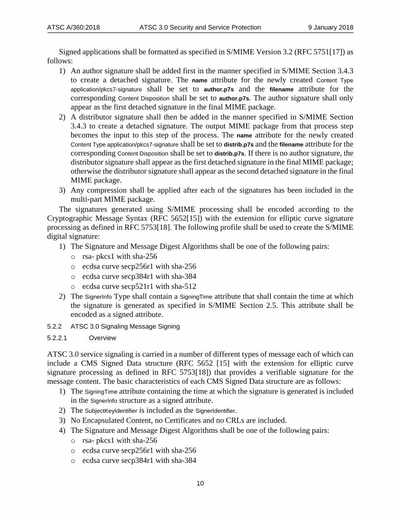
Signed applications shall be formatted as specified in S/MIME Version 3.2 (RFC 5751[17]) as follows:
1) An author signature shall be added first in the manner specified in S/MIME Section 3.4.3 to create a detached signature. The name attribute for the newly created Content Type application/pkcs7-signature shall be set to author.p7s and the filename attribute for the corresponding Content Disposition shall be set to author.p7s. The author signature shall only appear as the first detached signature in the final MIME package.
2) A distributor signature shall then be added in the manner specified in S/MIME Section 3.4.3 to create a detached signature. The output MIME package from that process step becomes the input to this step of the process. The name attribute for the newly created Content Type application/pkcs7-signature shall be set to distrib.p7s and the filename attribute for the corresponding Content Disposition shall be set to distrib.p7s. If there is no author signature, the distributor signature shall appear as the first detached signature in the final MIME package; otherwise the distributor signature shall appear as the second detached signature in the final MIME package.
3) Any compression shall be applied after each of the signatures has been included in the multi-part MIME package.
The signatures generated using S/MIME processing shall be encoded according to the Cryptographic Message Syntax (RFC 5652[15]) with the extension for elliptic curve signature processing as defined in RFC 5753[18]. The following profile shall be used to create the S/MIME digital signature:
1) The Signature and Message Digest Algorithms shall be one of the following pairs: o rsa- pkcs1 with sha-256 o ecdsa curve secp256r1 with sha-256 o ecdsa curve secp384r1 with sha-384 o ecdsa curve secp521r1 with sha-512
2) The SignerInfo Type shall contain a SigningTime attribute that shall contain the time at which the signature is generated as specified in S/MIME Section 2.5. This attribute shall be encoded as a signed attribute.
5.2.2 ATSC 3.0 Signaling Message Signing
5.2.2.1 Overview
ATSC 3.0 service signaling is carried in a number of different types of message each of which can include a CMS Signed Data structure (RFC 5652 [15] with the extension for elliptic curve signature processing as defined in RFC 5753[18]) that provides a verifiable signature for the message content. The basic characteristics of each CMS Signed Data structure are as follows:
1) The SigningTime attribute containing the time at which the signature is generated is included in the SignerInfo structure as a signed attribute.
2) The SubjectKeyIdentifier is included as the SignerIdentifier. 3) No Encapsulated Content, no Certificates and no CRLs are included. 4) The Signature and Message Digest Algorithms shall be one of the following pairs:
o rsa- pkcs1 with sha-256 o ecdsa curve secp256r1 with sha-256 o ecdsa curve secp384r1 with sha-384

ATSC A/360:2018 ATSC 3.0 Security and Service Protection 9 January 2018
11
o ecdsa curve secp521r1 with sha-512 (Additional characteristics are defined in each usage definition in subsequent sections.) In addition a Certification Data table is defined below to be carried in the low-level signaling. The
Certification Data table carries the necessary information for the authentication to a known root certificate and status verification of the keys used to sign signaling message content. The Certification Data table also carries information that allows the broadcaster to:
1) Manage a change of the signaling message signing key, 2) Define the life-span of certificate status response information, and 3) Request the receiver to handle signature verification failures in a particular manner.
5.2.2.2 Certificate and OCSP Response LLS Table This specification defines a new LLS table that carries X.509 Certificates and OCSP responses that are used to verify signed ATSC 3.0 Signaling Messages.
The Certification Data LLS table is allocated the LLS_table_id 0x06 and shall be represented as an XML document containing an CertificationData root element that conforms to the definitions in the XML schema that has namespace:
tag:atsc.org,2016:XMLSchemas/ATSC3/Delivery/CDT/1.0/
The XML schema xmlns short name should be "cdt". The Certification Data LLS table has the following informative description:
Element or Attribute Name Use Data Type Short Description CertificationData { 1 ToBeSignedData { 1 Certificates 1 to
n Base64
string A list of certificates that are used to authenticate a broadcaster
signature. This must include end-entity certificates authenticating the CurrentCert and the CMSSignedData signing certificate and any intermediate CA certificates used to validate these certificates. The Root CA certificate is not included in the list.
CurrentCert 1 Base64 String
SubjectKeyIdentifier for the certificate currently used to sign signaling messages
CertReplacement { 0 or 1
NextCert 1 Base64 String
SubjectKeyIdentifier for the certificate next used to sign signaling messages
@NextCertFrom 1 DateTime Earliest time at which NextCert can be validly used @CurrentCertUntil 1 DateTime Latest time at which CurrentCert can be validly used } @OCSPRefresh 1 Byte Integer number of hours for which an OCSPResponse is
considered valid from its producedAt time } CMSSignedData 1 Base64
String A CMS Signed Data structure authenticating the
ToBeSignedData contained in this table. OCSPResponse 1 to
n Base64
String A set of OCSP Responses that provide status information for
each of the Certificates }
CertificationData – Root element of the Certification Data Table.
ATSC A/360:2018 ATSC 3.0 Security and Service Protection 9 January 2018
12
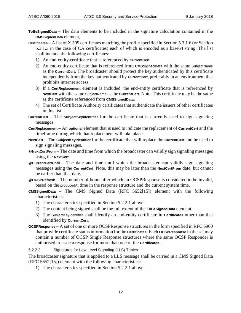
ToBeSignedData – The data elements to be included in the signature calculation contained in the CMSSignedData element,
Certificates – A list of X.509 certificates matching the profile specified in Section 5.3.1.6 (or Section 5.3.1.3 in the case of CA certificates) each of which is encoded as a base64 string. The list shall include the following certificates: 1) An end-entity certificate that is referenced by CurrentCert. 2) An end-entity certificate that is referenced from CMSSignedData with the same SubjectName
as the CurrentCert. The broadcaster should protect the key authenticated by this certificate independently from the key authenticated by CurrentCert, preferably in an environment that prohibits internet access.
3) If a CertReplacement element is included, the end-entity certificate that is referenced by NextCert with the same SubjectName as the CurrentCert. Note: This certificate may be the same as the certificate referenced from CMSSignedData.
4) The set of Certificate Authority certificates that authenticate the issuers of other certificates in this list.
CurrentCert – The SubjectKeyIdentifier for the certificate that is currently used to sign signaling messages.
CertReplacement – An optional element that is used to indicate the replacement of CurrentCert and the timeframe during which that replacement will take place.
NextCert – The SubjectKeyIdentifier for the certificate that will replace the CurrentCert and be used to sign signaling messages.
@NextCertFrom – The date and time from which the broadcaster can validly sign signaling messages using the NextCert.
@CurrentCertUntil – The date and time until which the broadcaster can validly sign signaling messages using the CurrentCert. Note, this may be later than the NextCertFrom date, but cannot be earlier than that date.
@OCSPRefresh – The number of hours after which an OCSPResponse is considered to be invalid, based on the producedAt time in the response structure and the current system time.
CMSSignedData – The CMS Signed Data (RFC 5652[15]) element with the following characteristics: 1) The characteristics specified in Section 5.2.2.1 above. 2) The content being signed shall be the full extent of the ToBeSignedData element. 3) The SubjectKeyIdentifier shall identify an end-entity certificate in Certificates other than that
identified by CurrentCert. OCSPResponse – A set of one or more OCSPResponse structures in the form specified in RFC 6960
that provide certificate status information for the Certificates. Each OCSPResponse in the set may contain a number of OCSP Single Response structures where the same OCSP Responder is authorised to issue a response for more than one of the Certificates.
5.2.2.3 Signatures for Low Level Signaling (LLS) Tables The broadcaster signature that is applied to a LLS message shall be carried in a CMS Signed Data (RFC 5652[15]) element with the following characteristics:
1) The characteristics specified in Section 5.2.2.1 above.

ATSC A/360:2018 ATSC 3.0 Security and Service Protection 9 January 2018
13
2) The content being signed is defined by the 4 byte table header (LLS_table_id, LLS_group_id, group_count_minus1, LLS_table_version) followed by the uncompressed content of the table being signed.
3) The SignerIdentifier shall match either the CurrentCert or, if present, the NextCert. The CMS Signed Data structure is appended to each signed table and shall be represented as
an XML document containing a CMSSignedData root element that conforms to the definitions in the XML schema that has namespace:
tag:atsc.org,2016:XMLSchemas/ATSC3/Delivery/CMSSD/1.0/
The XML schema xmlns short name should be "cmssd". The informative definition of this XML schema is as follows:
Element or Attribute Name
Use Data Type Short Description
CMSSignedData 1 Base64 string
A base64 encoded encapsulation of the CMS Signed Data structure (RFC 5652)
Any data compression shall be applied after the CMS Signed Data XML document has been appended to the message. 5.2.2.4 Signatures for Service Level Signaling carried over ROUTE/DASH Service Level Signaling over ROUTE/DASH is encapsulated in multi-part MIME packages and the broadcaster signs each of these packages in the manner specified in S/MIME [17] Section 3.4.3 with the CMS Signed Data structure profile as specified below to create a detached signature. The name attribute for the newly created Content Type application/pkcs7-signature shall be set to bcsig.p7s and the filename attribute for the corresponding Content Disposition shall be set to bcsig.p7s.
The signatures generated using S/MIME processing shall be encoded according to the Cryptographic Message Syntax (RFC 5652[15]). The following profile for the CMS Signed Data structure shall be used to create the S/MIME digital signature:
1) The characteristics specified in Section 5.2.2.1 above. 2) The SignerIdentifier shall match either the CurrentCert or, if present, the NextCert. All service level signaling encapsulated in multi-part MIME packages shall be signed by the
broadcaster. 5.2.2.5 Signatures for MMT Messages The broadcaster signature of an MMT message is across the entire MMT message (not including the signature), and shall be carried in a CMS Signed Data (RFC 5652[15]) structure with the following characteristics:
1) The characteristics specified in Section 5.2.2.1 above. 2) The SignerIdentifier shall match either the CurrentCert or, if present, the NextCert.
5.2.2.6 Receiver Signature Verification of Signaling Messages (Informative) The receiver is expected to undertake the following tasks to verify new instances of the signed signaling messages described in Sections 5.2.2.3, 5.2.2.4, and 5.2.2.5:
1) Verify that the signature contained in the CMS Signed Data structure is correct. 2) Verify that the SigningTime attribute in the CMS Signed Data structure is
a) Not greater than the System Time

ATSC A/360:2018 ATSC 3.0 Security and Service Protection 9 January 2018
14
b) Not less than the SigningTime of any previously received instance of the same type of signed signaling message.
3) Verify that the key used to sign the signaling message is authenticated by an unexpired end-entity certificate carried in Certification Data message, a) verify that this certificate has an extended key usage that includes id-atsc-kp-
signalingSigning, b) verify that this certificate contains a Subject Directory Attribute with an attribute of
type id-atsc-sdattr-bsid containing a comma separated list of hexadecimal numbers that include all of the bsids listed in the Service List Table for this broadcast stream.
c) and verify that this end-entity certificate’s SubjectKeyIdentifier matches either the CurrentCert or, if present, the NextCert.
4) Verify that, at the SigningTime of the signaling message, the CurrentCert or NextCert used to authenticate the signing key was valid for use according to the CurrentCertUntil and NextCertFrom dates respectively.
5) Verify that the producedAt date in the OCSPResponse that provides status information for the end-entity certificate plus the number of hours specified as the OCSPRefresh period in the Certification Data message exceeds the current System Time.
The receiver is expected to undertake the following tasks to verify a new instance of the Certification Data LLS Table described in Section 5.2.2.2:
1) Verify each of the certificate chains carried in the Certification Data message and that the first Certificate Authority certificate in that chain is issued by a Root Certificate Authority trusted by the receiver.
2) Verify that each of the certificates in the authenticating certificate chain has a status of good in the OCSPResponse.
3) Verify that the signature contained in CMSSignedData in the Certification Data message is valid and authenticated by a certificate chain in that message, and that the certificates in this chain have a status of good in the OCSPResponse corresponding to that certificate.
4) Verify that the producedAt date in each OCSPResponse plus the number of hours specified as the OCSPRefresh period in the Certification Data message exceeds the current System Time.
5) Revalidate the next instance of each signed signalling message that is received after the Certification Data LLS Table is successfully verified.
5.3 Certificates and Certificate Management This standard uses the Internet X.509 Public Key Infrastructure Profile (RFC 5280 [12]) as the base profile for certificates used by an ATSC 3.0 TLS server and ATSC 3.0 application signing authority authentication.
The following types of certificate are used by ATSC 3.0 devices during the authentication process:
• One or more root certificates. These are trusted self-signed certificates issued by a trusted certificate authority as the root of trust. Each certificate path validation process completes when a trusted root certificate is reached. TLS does not require the signature contained within these certificates to be checked.
• Certificate authority certificates. These certificates are issued by a trusted root certificate authority or a certificate authority whose certificate path can be validated to a trusted root certificate authority.

ATSC A/360:2018 ATSC 3.0 Security and Service Protection 9 January 2018
15
• TLS server certificates. These certificates are issued by a trusted certificate authority and are designated for use in server authentication.
• ATSC 3.0 application signer certificates. These certificates are issued by a trusted certificate authority and are designated for use in code signing.
• OCSP responder certificates. These certificates are issued by a trusted certificate authority and are designated for use in OCSP responder authentication.
The client is expected to perform certificate chain validation as specified in RFC 5280 [12] using the certificate status information provided by the ATSC 3.0 server in stapled OCSP Response messages (see Sections 5.1.1.5 and 5.5.2) as a reliable source for revocation information. 5.3.1 Certificate Profiles The profile specified in RFC 5280 [12] is further constrained for certificates used in ATSC 3.0. 5.3.1.1 General All ATSC 3.0 certificates shall be X.509 version 3 certificates.
All keys contained in ATSC 3.0 certificates shall be either RSA keys with a minimum size of 2048 bits encoded as specified in RFC 3279 [6] or ECDSA keys which use the elliptic curve groups and point format defined above (Sections 5.1.1.2 and 5.1.1.3) and encoded as specified in RFC 5480 [14].
All RSA signatures contained in ATSC 3.0 certificates shall be encoded according to the RSA signature algorithms specified in RFC 3279 [6] and RFC 4055 [7].
All ECDSA signatures contained in ATSC 3.0 certificates shall be encoded according to the ECDSA signature algorithms specified in RFC 5758 [19] and shall use one of the hash algorithms specified above (Sections 5.1.1.1 and 5.1.1.3) for use with the ECDSA signature algorithm.
All ATSC 3.0 certificates shall contain a Key Usage extension containing at least the digitalSignature value and with values constrained as specified in RFC 3279 [6] and RFC 4055 [7].
ATSC 3.0 devices need not process the Authority Information Access or the Subject Information Access extensions. 5.3.1.2 Root Certificate Profile The RSA key size for any root certificate shall be at least 2048 bits and should be 4096 bits.
The ECDSA key size for any root certificate shall be at least 384 bits. 5.3.1.3 Certificate Authority Certificate Profile The RSA key size for any certificate authority certificate shall be at least 2048 bits.
The ECDSA key size for any certificate authority certificate shall be at least 256 bits. 5.3.1.4 Server Authentication Certificate Profile The RSA key size for this certificate shall be at least 2048 bits.
The ECDSA key size for any server authentication certificate shall be at least 256 bits. The Subject Alternative Name extension shall be present and shall include either the DNS
Name or the IP Address of the server being authenticated. The Extended Key Usage extension shall be present and shall be set to the value id-kp-serverAuth
to indicate that the certificate is used in TLS server authentication. 5.3.1.5 ATSC 3.0 Application Signer Certificate Profile The RSA key size for any application signer certificate shall be at least 2048 bits.

ATSC A/360:2018 ATSC 3.0 Security and Service Protection 9 January 2018
16
The ECDSA key size for any application signer certificate shall be at least 256 bits. The Key Usage extension shall be marked as critical and shall include only the digitalSignature
value. The Extended Key Usage extension shall be present, marked as critical, and shall be include
the value id-kp-codeSigning to indicate that the certificate is used in the signing of downloadable executable code. For author code signing certificates this extension shall also include the value id-atsc-kp-author. For distributor code signing certificates this extension shall include the value id-atsc-kp-distributor. 5.3.1.6 ATSC 3.0 Broadcast Signaling Signer Certificate Profile The RSA key size for any OCSP responder certificate shall be at least 2048 bits.
The Key Usage extension shall be marked as critical and shall include only the digitalSignature value.
The Extended Key Usage extension shall be present, shall be marked as critical, and shall include an attribute of type id-atsc-kp-signalingSigning to indicate that the certificate is used in the signing of ATSC signaling constructs.
The Subject Directory Attributes extension shall be present, not marked as critical, and shall include an attribute of type id-atsc-sdattr-bsid with a value that contains a comma separated list of four byte hexadecimal encoded numbers each representing a Broadcast Service Identifier. 5.3.1.7 OCSP Responder Certificate Profile The RSA key size for any OCSP responder certificate shall be at least 2048 bits.
The ECDSA key size for any OCSP responder certificate shall be at least 256 bits. The Extended Key Usage extension shall be present and shall be set to the value id-kp-
OCSPSigning to indicate that the certificate is used to sign OCSP responses.
5.4 ATSC 3.0 Client Certificate Storage See CEA 2053 [29], which describes secure storage of certificates, and the mechanism(s) for modifying certificates used by client devices.
Clients provide secure storage for the following set of certificates: • The set of trusted root certificates • The set of trusted signing certificate authority certificates • The set of trusted OCSP responder certificates
Certificates are changed over time, either by client device code download or by other means.
5.5 Certificate Revocation and Status Information The management of certificate status is under the control of the issuing authority which works according to their defined certification practices and policies. Each certificate authority that issues certificates used by an ATSC 3.0 server or ATSC 3.0 application signing authority is responsible for the timely supply of certificate status information to the OCSP responder(s). The specific methods by which this information is made available to the OCSP responder are beyond the scope of this specification. 5.5.1 Certificate Revocation and Status Information for TLS Server Certificates An ATSC 3.0 server shall request certificate status information from an OCSP responder at least once per minute for each server authentication certificate that it provides as server identification when establishing a TLS connection. The request shall be in the format specified in RFC 6960

ATSC A/360:2018 ATSC 3.0 Security and Service Protection 9 January 2018
17
[23], shall be unsigned and the only extension included in the request shall be the Preferred Signature Algorithms extension.
Note: In order to satisfy clients that support different signature algorithms, a server may need to request certificate status information from the same OCSP responder using different values in the Preferred Signature Algorithm extension.
5.5.2 Certificate Revocation and Status Information for ATSC 3.0 Application Signing Certificates An ATSC 3.0 application signing authority shall request certificate status information from an OCSP responder for the signing authority certificate that validates the signing key each time that key is used in a signing operation. The OCSP request shall indicate that the preferred signature algorithm to be used by the OCSP responder is RSA with SHA-256.
The SigningTime associated with the ATSC 3.0 application signature and the producedAt time of the corresponding OCSP Response providing the status of the signing authority certificate shall differ by no more than one minute. The ATSC 3.0 application signing authority shall include the OCSP Response in the signed application and should not issue a signed application where the OCSP Response indicates that the status of the signing authority certificate (as specified in RFC 6960 [23]) is other than “good”.
The application signing authority shall include an OCSPResponse in the otherRevInfoFormat field of each Cryptographic Message Syntax (RFC 5652[15]) formatted digital signature contained in the signed multi-part MIME content. The OCSPResponse shall conform to the format specified in RFC 5940[21].
A client uses the OCSP Response data that it receives to verify that the certificates that authenticate the application signing authority are valid at the time the application is signed. See CEA 2053 [29].
5.6 Pre-Shared Key Encrypted Connections This section describes a general method by which two devices, known as the client device and the server device, can derive a pre-shared key and use that key to establish an encrypted connection. This method is based on the exchange of universally unique identifiers (UUID) [28] between the two devices and of the same input keying material (IKM) on each device. The derived pre-shared keys can then be used to establish a TLS 1.3 connection between the devices, using the TLS 1.3 Pre-Shared Key Exchange Parameters defined in Section 5.6.2.
Implementation of this section requires implementation all of the normative provisions of this Section 5.6.
When this section is used to establish an encrypted connection between a Companion Device (CD) application and a Primary Device (PD) per A/338 [30], the CD acts as the client, the PD acts as the server. 5.6.1 Pre-shared Key Registration
5.6.1.1 Pre-Shared Key Identifier Each pre-shared key installed on a client shall be referenced by the universally unique identifier (UUID) of the corresponding server with which it shares the key.
Each pre-shared key installed on a server shall be referenced by the universally unique identifier (UUID) of the corresponding client with which it shares the key.
For example, UUIDs are provided in the device discovery protocol specified in A/338 [30].

ATSC A/360:2018 ATSC 3.0 Security and Service Protection 9 January 2018
18
5.6.1.2 Pre-Shared Key Hash Algorithm The pre-shared key shall be used with the sha256 hash algorithm in the TLS 1.3 Key Schedule process (see Section 7.1 of [26]) when deriving secrets for use in TLS 1.3. 5.6.1.3 Pre-Shared Key Generation The pre-shared key shall be derived from input keying material (IKM) using the PBKDF2 algorithm specified in RFC 8018 [25], as follows:
1) Create a salt by concatenating the server’s 128-bit UUID and the client’s 128-bit UUID in that order, giving a 256-bit binary value.
2) Set the pre-shared key to PBKDF2(IKM, salt, 50000, 32) using HMAC-sha256 as the underlying pseudorandom functions as described in RFC 8018 [25].
5.6.1.4 Key Generation Test Vectors Correct implementation of the above pre-shared key generation using the below example input parameters yields the below output parameters.
Input: Server UUID = 0x123e4567e89b12d3a456426655440000 Client UUID = 0x98734716276497582763764874687252 IKM = ‘UserPassword' (0x5573657250617373776f7264)
Intermediate results: Salt = 0x123e4567e89b12d3a45642665544000098734716276497582763764874687252
Output: PSK = 0xf7a28206cfad1076eba1fce76245e012f357f5f70bcbe407f03d53ca8265de32
5.6.1.5 Initial Communication When the pre-shared keys are derived, both client and server must be provided with IKM that consists of 32 or fewer ASCII characters. Such provision of IKM to the client and server is out of scope of this document, however it is expected that the end-user will provide a passcode, PIN or similar as IKM to both client and server. The IKM shall not be stored in persistent memory in either client or server, and the client and server shall not reuse IKM. 5.6.1.6 Pre-Shared Key Storage The client and server shall store each pre-shared key in a trusted keystore which limits key usage to those algorithms and applications used to establish a TLS connection. The ability to enter new pre-shared keys into the trusted keystore or to delete pre-shared keys from the trusted keystore shall be limited to a Privileged Application on the client and server. If a secure hardware based trusted keystore is available on the client or server device, this should be used to store the pre-shared keys. 5.6.2 TLS 1.3 Pre-Shared Key Exchange Parameters A client device acting as a TLS Client and a server device acting as a TLS Server may establish a TLS 1.3 connection using pre-shared keys derived according to Section 5.6.1. The TLS 1.3 Server Connection Negotiation parameters defined in Section 5.1.1.2 shall be used with the pre-shared keys to establish this connection.

ATSC A/360:2018 ATSC 3.0 Security and Service Protection 9 January 2018
19
The TLS client handshake request indicates the use of the TLS 1.3 protocol and the TLS server shall not negotiate a downgrade to a previous version of TLS. The TLS client shall set the Pre-Shared Key Exchange Mode to psk_dhe_ek to enable an ephemeral ECDHE key to be established. The TLS client handshake request is not expected to include early data and the TLS server shall not accept any early data received from the client.
Server devices that have established a TLS 1.3 connection using pre-shared keys should support TLS Session Resumption (see Section 5.1.1.6) for those connections. 5.6.2.1 Pre-Shared Key Hash Algorithm The pre-shared key shall be used with the sha256 hash algorithm in the TLS 1.3 Key Schedule process (see Section 7.1 of [22]) when deriving secrets for use in TLS 1.3.
5.7 Content Protection 5.7.1 Common Encryption ATSC 3.0 uses the DASH-IF ATSC Profile [5] as the media container that will be sent through the broadcast emission to the receiver for consumption. MPEG Common Encryption (CENC) [2] has been specified as a digital rights management system suitable for use with ISO BMFF. Any media that requires DRM encryption shall use MPEG Common Encryption (CENC).
The Common Encryption (cenc) protection scheme specifies encryption parameters that can be applied by a scrambling system, along with key mapping methods via common key identifier (KID) for use by different DRM systems, such that the same encrypted version of a file can be handled by different DRM systems which can store proprietary information for licensing and key retrieval in designated metadata boxes of the ISO BMFF file – specifically, the Protection System Specific Header Box (pssh) as defined in ISO/IEC 23001-7 [2].
The key advantage of CENC is that by providing a common way to encrypt content, it decouples the content encryption from the key acquisition and thus provides support for multiple DRM systems.
The CENC mechanism only encrypts media samples or parts thereof and leaves the ISOBMFF metadata such as the file and track structure boxes un-encrypted to enable players to recognize and read the file correctly and acquire any required license. CENC supports the encryption of NAL-based video encoding formats such as AVC and HEVC, thus offering sub-sample encryption capability, where only the video data of a sub-sample is encrypted, while the NAL header is not. This flexibility can be used to offer a free preview of the video, enable editing and processing of the video, or provide free access to some service components such as audio. By providing offsets to the encrypted byte ranges inside a sample in an ISOBMFF “mdat” box, players can easily process the file and pass the encrypted chunks to the decryptor for decryption and playback.
In order for decryption to work, CENC provides the following information in the ISOBMFF: • Key Identifiers (KID): a key ID must be associated with every encrypted sample in a track.
In case a single key is used for the whole track. • Initialization Vectors (IV): the IV, a random number used to initialize an encryption
function, is used for randomization and removal of semantics and is essential for strong protection. For every sample, the IV must be known in order to be able to construct the decryption key.
• License Acquisition Information: information about license acquisition is specific to each DRM system. The player needs to support at least one of the DRM systems that offer access to the encrypted stream.

ATSC A/360:2018 ATSC 3.0 Security and Service Protection 9 January 2018
20
CENC defines a way to store the previous information in the ISOBMFF. The Key Identifiers may be provided:
• As the default_KID in the track encryption box “tenc”, when a single key applies to the whole track,
• As a key for a set of samples that share the same encryption key, provided in a sample grouping structure using the sample group description box “sgpd”.
The IV for every sample is provided as part of the sample auxiliary information in the “mdat” box or in the “senc” box together with information about the position of the encrypted chunks.
The license acquisition information is provided as part of the protection system specific header box “pssh”, where each DRM system is identified by a SystemID. The “pssh” box also provides a list of the provided Key Identifiers and opaque system-specific information that describes how to acquire the keys identified by the supported key ids.
Figure 5.1 depicts the encrypted track structure.
Figure 5.1 Storage of CENC related information.
5.7.2 Encrypted Media Extensions W3C Encrypted Media Extensions (EME) [3] specifies JavaScript APIs which enable a web application to facilitate the exchange of decryption keys between a device-resident DRM system agent, referred to as the Content Decryption Module (CDM), and a key source or license server located somewhere on the network, to support the playback of encrypted audio and video media content. EME is based on the HTML5 Media Source Extensions specification [4] which enables adaptive bitrate streaming in HTML5 using, DASH-IF ATSC Profile [5] with MPEG-CENC (Common Encryption) [2] protected content. The architecture of EME is depicted in Figure 5.2, which depicts the primary interactions of the EME workflow between the functional entities involved in the detection of encrypted content and the subsequent acquisition of license and key material, to enable content decryption and playout.

ATSC A/360:2018 ATSC 3.0 Security and Service Protection 9 January 2018
21
Content Decryption Module (CDM)
HTML5 WebRuntime Engine
Decr
ypt R
eque
st
Media PlayerLi
cens
e Re
quie
st
Web Application
License Server
Get L
icen
se
Lice
nse
Upd
ate
KeyS
tore
Upd
ate
KeyS
tore
Decr
ypte
d Fr
ame
ATSC 3.0 Receiver
1
3
2
45
6
7 8
Figure 5.2 Encrypted Media Extensions workflow.
The principal objects in EME are MediaKeySession and MediaKeys. The web application creates a MediaKeySession object, which represents the lifetime of a license and its key(s), by calling createSession() on the MediaKeys object. The app initiates the request for a license by passing the media data obtained in the encrypted event handler to the CDM. In turn, the CDM for the selected DRM system will generate a data blob (license request) and deliver it back to the app, which will then send that request to the license server. The returned license from the server is then passed by the app to the CDM, by using the update() method of the MediaKeySession. The CDM and/or the browser will use keys stored in the key session to decrypt media samples as they are encountered. The CDM may be either embedded in the web browser, or run in a trusted environment, depending on the required level of security, in passing the decrypted frames to a decoder.

ATSC A/360:2018 ATSC 3.0 Security and Service Protection 9 January 2018
22
5.7.3 CENC and EME Support ATSC 3.0 service and content may be protected using common encryption and one or more DRM systems. Multiple licenses to a single service or content may be available through multiple DRM systems simultaneously.
A DRM-protected ATSC 3.0 service or content shall be encrypted according to the Common Encryption standard [2] using the AES-128 algorithm in either the CTR or the CBC mode. 5.7.3.1 MMT Support for CENC and EME MMT supports common encryption through use of the SI descriptor. For more information, see ATSC A/331 [31] and ISO/IEC 23008-1 [34] subclause 10.5.5. 5.7.3.2 ROUTE/DASH Support for CENC and EME ROUTE/DASH support for CENC may be found in [5], Section 7. Information on the interaction of ROUTE/DASH and EME is provided in Annex A.
5.8 Backend Business Systems It is beyond the scope of this specification to define the detailed components used in the preparation of broadcast streams that carry encrypted content. DASH Guidelines for Implementations: DASH-IF Interoperability Points [8] Section 7.8 provides an overview of the logical roles and workflow of the components of a system for the exchange of content protection information.
5.9 DRM License and Key Delivery for Broadcast-Only Devices See A/331 for specification of delivery of DRM licenses and keys in the broadcast emission.

ATSC A/360:2018 ATSC 3.0 Security and Service Protection, Annex A 9 January 2018
23
Annex A: ROUTE/DASH Client Processing for Common Encryption (CENC) and Encrypted Media Extensions
(EME) (Informative)
A.1 INTRODUCTION This Annex describes the operation of a ROUTE-enabled ATSC receiver when accessing CENC-protected media.
ROUTE/DASH supports the Common Encryption (CENC) framework for multiple DRM systems to protect DASH-formatted streaming service content. ROUTE/DASH includes protection system specific and proprietary signaling information delivered in two way: a) in predetermined locations in the MPD, and b) carried inband to the DASH content, in designated metadata boxes of the ISO BMFF format for movie fragments [2], in accordance to the usage as defined in ISO/IEC 23001-7 [2]. Most of the details can be found in the DASH-IF IOP specification [33]., and are compliant to the DASH-IF Broadcast IOP specification [5].
A.1.1 Basic CENC Operation in ROUTE/DASH This section describes the basic mechanisms of how DASH-formatted streaming content, protected by a DRM system, and delivered by the ROUTE protocol, can be decrypted and played out. It describes, in the context of CENC and EME, the required interactions within the receiver and between the receiver and a license server, for license and key acquisition and subsequent content decryption and playout.
Two alternative methods are described using message/interaction flows. In the first (see Section A.1.1.1), acquisition of the DRM license and content key by the CDM occurs prior to the start of the streaming program delivery. In the second method (as described in Section A.1.1.2), acquisition of the DRM license and content key by the CDM occurs during the program delivery. The first method, by bootstrapping the license and key acquisition prior to the start of the broadcast program, may be preferable over the second in reducing start-up delay for playing out of DRM-protected content, although the actual gains depend on the specific service requirements and practical license acquisition latency over the broadband network.
A.1.1.1 License Acquisition Prior to Program Delivery
Figure A.1 is an example message flow illustrating the method whereby the ContentProtection descriptor in the MPD is used to provide the affiliated metadata, such as license server’s URL and default KID to the CDM. This triggers the CDM to request and obtain the DRM license, and associated key material prior to the media delivery. When the encrypted media content is later broadcast, the receiver has the necessary decryption keys to render the content immediately.

ATSC A/360:2018 ATSC 3.0 Security and Service Protection, Annex A 9 January 2018
24
CDM(DRM System X)
Browser incl.Media Player
Application(DASH Client) Broadcast Server License Server
(DRM System X)
1. Broadcast MPD
3. EME interactions between App and browser to acquire info on DRM System_X and creation of related EME media keys, media system access and media key session objects
4. Request (initializationdata from MPD)
5. License Request(initialization data)
6. Fires message eventfor license acquisition
7. License request8. License request
2. Detects ContentProtectionDescriptor with License Server URL of DRM System_X for associated program
9. User and deviceauthentication and authorization forlicense granting
10. License grant11. Provide license(via update() event)
12. Provide license
14. CDM decrypts and stores license which defines usage permissions and constraints, along with content key(s) for later use in decryption of broadcaststreaming content
15. Broadcast via ROUTE ofencrypted DASH streaming mediaby content key of DRM System_X
16.Encrypted media17. Encrypted media
18. CDM decrypts the media using the content key(s) in the license
19. Decrypted media
20. Media playout begins
0. Assumed business relationship betweenBroadcaster and DRM System X provider
13. License reception ACK
Figure A.1 DRM license and key acquisition before start of program in
ROUTE/DASH.
A.1.1.2 License Acquisition During Program Delivery
Figure A.2 is an example message flow illustrating the method whereby the protection system related metadata carried in the DASH Segments, specifically the ‘pssh’ box in the ‘moov’ or ‘moof’ box is used to provide the affiliated metadata, such as license server’s URL and default KID to the CDM. During the interval that it takes for the CDM to request and obtain the DRM license, and associated key material, the program cannot be rendered. Due to the greater start-up delay associated with this method, it is suggested that the alternative method in Section A.1.1.1 be employed by the broadcaster.

ATSC A/360:2018 ATSC 3.0 Security and Service Protection, Annex A 9 January 2018
25
CDM(DRM System_X)
Browser incl.Media Player
Application(DASH Client) Broadcast Server License Server
(DRM System_X)
1. Broadcast MPD
5. EME interactions between App and browser to acquire info on DRM System_X and creation of related EME media keys, media system access and media key session objects
6. Request (initializationdata from ‘pssh’)7. License Request
(initialization data)
8. Fires message eventfor license acquisition 9. License request
10. License request
11. User and deviceauthentication and authorization forlicense granting
12. License grant13. Provide license(via update() event)
14. Provide license
16. CDM decrypts and stores license which defines usage permissions and constraints, along with content key(s) for use in decryption of broadcaststreaming content
2. Broadcast via ROUTE ofencrypted DASH streaming mediaby content key of DRM System_X
17. Encrypted media
18. CDM decrypts the media using the content key(s) in the license
19. Decrypted media
20. Media playout begins
3.Encrypted mediadelivered to Player
4. Player detects encrypted media samples for which it has no appropriate decryption key
15. License reception ACK
0. Assumed business relationship betweenBroadcaster and DRM System_X provider
Figure A.2 DRM license and key acquisition during program delivery in
ROUTE/DASH.
A.1.2 Solution Framework for DRM and CENC ISO-IEC 23001-7 [2] represents the normative standard for common encryption in conjunction with ISO BMFF [2]., and includes the following technology components used for DRM protection of streaming media carried by ROUTE/DASH:
• Common encryption of NAL structure video and other media with AES-128 CTR mode • Support for decryption of individual Representations by one or more DRM systems • Key rotation to enable the change of the content encryption keys over time • Extension of the ContentProtection descriptor to enable the signaling of default_KID
and ‘pssh’ parameters in the MPD The primary DRM related signaling components and tools available for use in ROUTE/DASH
are as follows: 1) The ContentProtection descriptor in the MPD which contains the URI for signaling of
the use of Common Encryption or the specific DRM scheme being used.

ATSC A/360:2018 ATSC 3.0 Security and Service Protection, Annex A 9 January 2018
26
2) Parameters of the ‘tenc’ box, carried as part of protection scheme information in the movie box (‘moov’) of the Initialization Segment, which specify encryption parameters and default_KID. The default_KID information may also be carried out-of-band in the MPD.
3) Signaling of common encryption sample auxiliary information in the form of initialization vectors and subsample encryption ranges, if applicable, using the ‘senc box as defined in ISO/IEC 23001-7 [2], or via the SampleAuxiliaryInformationSizesBox (‘saiz’) and a SampleAuxiliaryInformationOffsetsBox ('saio').
4) ‘pssh’ license acquisition data or keys for each DRM system in a format that is protection system specific. ‘pssh’ refers to the Protection System Specific Header box as defined in ISO/IEC 23001-7 [2], and which may be stored in the Initialization Segment or in Media Segments. It may also be present in a cenc:pssh element in the MPD. Note that while the presence of cenc:pssh information in the MPD increases the MPD size, it may allow faster parsing, earlier access, and addition of DRM systems without content modification.
5) Key rotation to enable modification over time in the entitlement for access to continuous live content. Details on how key rotation operates in the protection of broadcast DASH streaming content can be found in the DASH-IF Interoperability Points documents [33], [5] (nb. Section 7.5 of [33] and Section 7.4 of [33]).
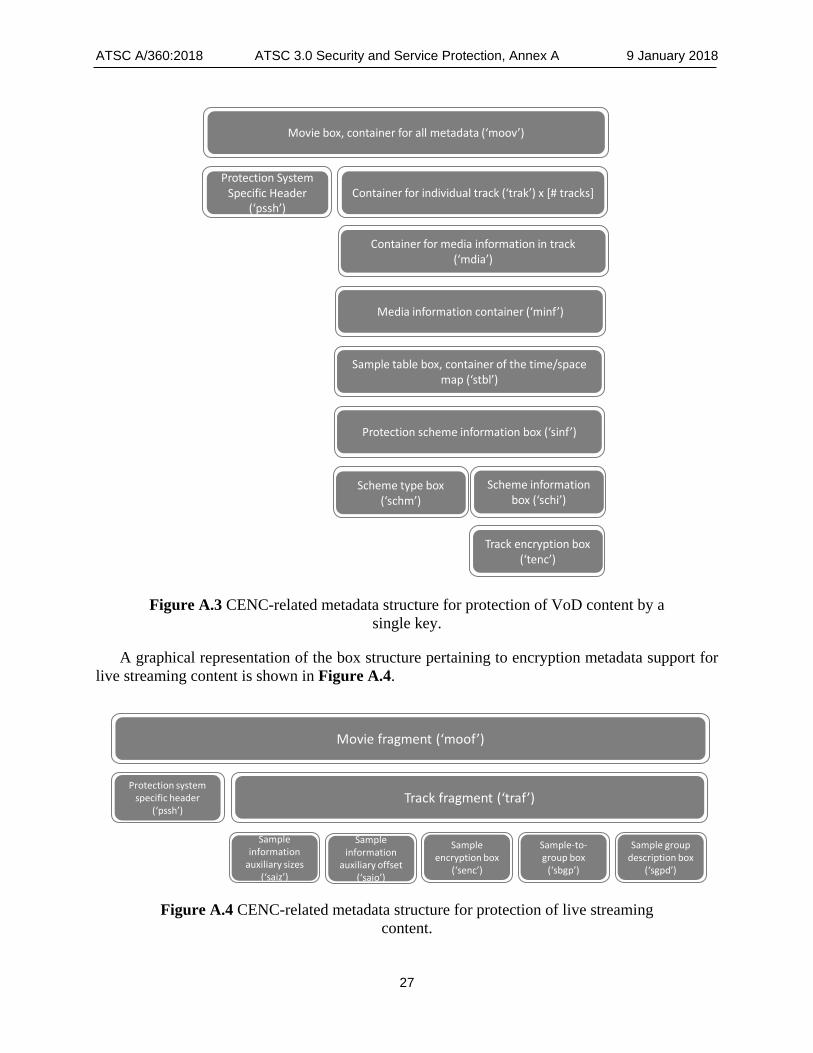
A graphical representation of the box structure pertaining to encryption metadata support for video-on-demand (VoD) content is shown in Figure A.3.
ATSC A/360:2018 ATSC 3.0 Security and Service Protection, Annex A 9 January 2018
27
Movie box, container for all metadata (‘moov’)
Container for individual track (‘trak’) x [# tracks]Protection System
Specific Header(‘pssh’)
Container for media information in track (‘mdia’)
Media information container (‘minf’)
Sample table box, container of the time/space map (‘stbl’)
Protection scheme information box (‘sinf’)
Scheme type box (‘schm’)
Scheme information box (‘schi’)
Track encryption box (‘tenc’)
Figure A.3 CENC-related metadata structure for protection of VoD content by a
single key.
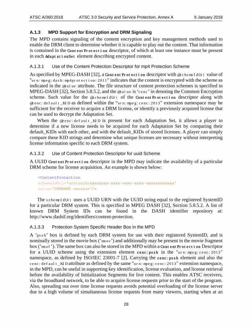
A graphical representation of the box structure pertaining to encryption metadata support for live streaming content is shown in Figure A.4.
Movie fragment (‘moof’)
Protection systemspecific header
(‘pssh’)Track fragment (‘traf’)
Sample information
auxiliary sizes (‘saiz’)
Sample information
auxiliary offset (‘saio’)
Sample encryption box
(‘senc’)
Sample-to-group box
(‘sbgp’)
Sample group description box
(‘sgpd’)
Figure A.4 CENC-related metadata structure for protection of live streaming
content.
ATSC A/360:2018 ATSC 3.0 Security and Service Protection, Annex A 9 January 2018
28
A.1.3 MPD Support for Encryption and DRM Signaling The MPD contains signaling of the content encryption and key management methods used to enable the DRM client to determine whether it is capable to play out the content. That information is contained in the ContentProtection descriptor, of which at least one instance must be present in each AdaptationSet element describing encrypted content.
A.1.3.1 Use of the Content Protection Descriptor for mp4 Protection Scheme
As specified by MPEG-DASH [32], a ContentProtection descriptor with @schemeIdUri value of "urn:mpeg:dash:mp4protection:2011" indicates that the content is encrypted with the scheme as indicated in the @value attribute. The file structure of content protection schemes is specified in MPEG-DASH [32], Section 5.8.5.2, and the @value is ‘cenc’ in denoting the Common Encryption scheme. Such value for the @schemeIdUri of the ContentProtection descriptor along with @cenc:default_KID as defined within the “urn:mpeg:cenc:2013" extension namespace may be sufficient for the receiver to acquire a DRM license, or identify a previously acquired license that can be used to decrypt the Adaptation Set.
When the @cenc:default_KID is present for each Adaptation Set, it allows a player to determine if a new license needs to be acquired for each Adaptation Set by comparing their default_KIDs with each other, and with the default_KIDs of stored licenses. A player can simply compare these KID strings and determine what unique licenses are necessary without interpreting license information specific to each DRM system.
A.1.3.2 Use of Content Protection Descriptor for uuid Scheme
A UUID ContentProtection descriptor in the MPD may indicate the availability of a particular DRM scheme for license acquisition. An example is shown below:
<ContentProtection
schemeIdUri="urn:uuid:xxxxxxxx-xxxx-xxxx-xxxx-xxxxxxxxxxxx"
value="DRMNAME version"/>
The schemeIdUri uses a UUID URN with the UUID string equal to the registered SystemID for a particular DRM system. This is specified in MPEG DASH [32], Section 5.8.5.2. A list of known DRM System IDs can be found in the DASH identifier repository at: http://www.dashif.org/identifiers/content-protection.
A.1.3.3 Protection System Specific Header Box in the MPD
A ’pssh’ box is defined by each DRM system for use with their registered SystemID, and is nominally stored in the movie box (‘moov’) and additionally may be present in the movie fragment box (‘moof’). The same box can also be stored in the MPD within a ContentProtection Descriptor for a UUID scheme using the extension element cenc:pssh in the "urn:mpeg:cenc:2013" namespace, as defined by ISO/IEC 23001-7 [2]. Carrying the cenc:pssh element and also the cenc:default_KID attribute as defined by the same "urn:mpeg:cenc:2013" extension namespace, in the MPD, can be useful in supporting key identification, license evaluation, and license retrieval before the availability of Initialization Segments for live content. This enables ATSC receivers, via the broadband network, to be able to acquire license requests prior to the start of the program. Also, spreading out over time license requests avoids potential overloading of the license server due to a high volume of simultaneous license requests from many viewers, starting when at an

ATSC A/360:2018 ATSC 3.0 Security and Service Protection, Annex A 9 January 2018
29
Initialization Segment containing license acquisition information in ‘pssh’ becomes available. With cenc:default_KID indicated in the mp4protection ContentProtection descriptor for each Adaptation Set, the DRM client in the receiver can determine whether
• the associated decryption key for the program is available to the viewer (e.g., without purchase or subscription),
• if the key is already downloaded, or • which license the client should download before the @availabilityStartTime of the
program, based on the default_KID of each Adaptation Set element selected.
End of Document