
’07 YZF-R6 - motorace.BYmotorace.by/images/manuals/2007_R6_Kit_Manual.pdf · refer to the YZF-R6...
53
’07 YZF-R6 SS KIT MANUAL The Performance Edge for excellent riders
Transcript of ’07 YZF-R6 - motorace.BYmotorace.by/images/manuals/2007_R6_Kit_Manual.pdf · refer to the YZF-R6...

’07 YZF-R6SS KIT MANUAL
The Performance Edgefor excellent riders

Introduction• Please understand that these parts are not covered by warranty.• The manufacturer does not take any responsibility for problems caused by these parts.• These kit parts are intended exclusively for racing purposes. You are strictly requested not
to use them on public roads.• The specifications and usage methods of these kit parts along with the contents of this
manual are subject to change without notice for improvement.• This manual is intended for persons with knowledge and experience of motorcycles. Please
refer to the YZF-R6 service manual, which shall be published from YAMAHA MOTORCO.LTD., for information on part assembly and maintenance.
• The name of kits and parts are all described in English.• The YZF-R6 racing kit comprises of the parts allowing the base Machine YZF-R6 to comply
with the FIM SUPER SPORT regulations.

CONTENTS1 Basic Specifications ..................................................................................... 1
2 Kit Parts ......................................................................................................... 2
2-1 Engine Parts.................................................................................................... 21. Maintenance Set (2C0-MAINT-70) ....................................................................... 22. Spark plug set (5FL-R045Q-70)............................................................................ 33. Head Gasket ......................................................................................................... 44. Cam Shaft and Cam Sprocket .............................................................................. 55. Valve Spring Set (2C0-A2110-70) ........................................................................ 66. Large-Sized Radiator Set (2CO-A2460-70) .......................................................... 67. Oil Pump (2C0-13300-70)..................................................................................... 68. Air Funnel Set (2CO-A4460-70)............................................................................ 69. Throttle Body Clamp Complete (2CO-1351A-70) ................................................. 710. Exhaust Set (2CO-A4600-80) ............................................................................... 811. Clutch Spring Set (2CO-A6330-70) ...................................................................... 812. Friction Plate Set (2CO-A6321-70) ....................................................................... 813. AIS Plug Set (5SL-A4890-70) ............................................................................... 914. Transmission Set ................................................................................................ 1015. Optional Gear Set ............................................................................................... 1316. Drive Sprocket .................................................................................................... 1417. Sprocket Nut Set (2C0-A7463-70) ...................................................................... 1518. ACM Set (2C0-F1400-71) ................................................................................... 1619. Wire Harness Set (2C0-F2590-80) ..................................................................... 1720. Engine Control Unit (ECU).................................................................................. 1921. Cable Interface (2C0-8533A-70)......................................................................... 2022. 2D Data Logger................................................................................................... 2323. Engine Protector Set (2C0-A5491-70) ................................................................ 2424. Chassis Protector Set ......................................................................................... 25
2-2 Vehicle Accessories..................................................................................... 2725. Oil Catch Tank Set (2C0-C1707-70)................................................................... 2726. Front Fork Spring Set.......................................................................................... 2827. Steering Damper Stay Set (2C0-C3495-80) ....................................................... 2928. Front Spare Wheel Assembly (2C0-25100-70)................................................... 3029. Rear Spare Wheel Assembly (2C0-25300-70) ................................................... 3130. Throttle Set (2C0-C6300-70) .............................................................................. 3231. Front Stay Set (2C0-C8350-70) .......................................................................... 3332. Tightening Torque List ........................................................................................ 34
YZF-R6 Wire Connecting Diagram ................................................................ 49

– 1 –
1 Basic Specifications
SpecDisplacement 599ccMaximum engine speed (limiter controlled speed)
16000rpm
Bore/Stroke 67.0 × 42.5mmValve timing (event angle)
INT.EXT.
= 110°= 110°
Squish height 0.60mmClearance between the valve and the piston
INT.EXT.
= 1.10 12° ATDC= 1.62 12° BTDC
Clearance of valves (tappet)INT.EXT.
= 0.20 targeted (0.18 ~ 0.22)= 0.25 targeted (0.23 ~ 0.27)
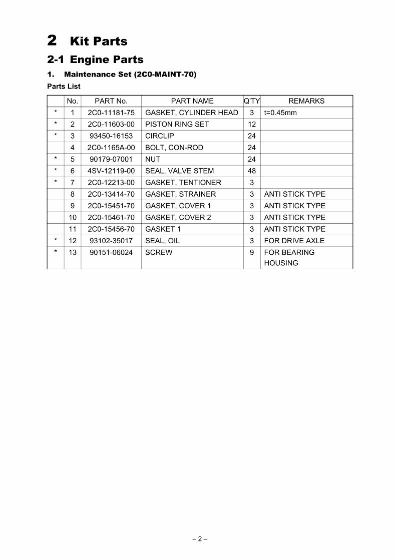
2 Kit Parts2-1 Engine Parts1. Maintenance Set (2C0-MAINT-70)Parts List
No. PART No. PART NAME Q'TY REMARKS* 1 2C0-11181-75 GASKET, CYLINDER HEAD 3 t=0.45mm* 2 2C0-11603-00 PISTON RING SET 12* 3 93450-16153 CIRCLIP 24
4 2C0-1165A-00 BOLT, CON-ROD 24* 5 90179-07001 NUT 24* 6 4SV-12119-00 SEAL, VALVE STEM 48* 7 2C0-12213-00 GASKET, TENTIONER 3
8 2C0-13414-70 GASKET, STRAINER 3 ANTI STICK TYPE9 2C0-15451-70 GASKET, COVER 1 3 ANTI STICK TYPE
10 2C0-15461-70 GASKET, COVER 2 3 ANTI STICK TYPE11 2C0-15456-70 GASKET 1 3 ANTI STICK TYPE
* 12 93102-35017 SEAL, OIL 3 FOR DRIVE AXLE* 13 90151-06024 SCREW 9 FOR BEARING
HOUSING
– 2 –

2. Spark plug set (5FL-R045Q-70)
CAUTION:Since these spark plugs have a copper gasket, caution is needed during installation on thefollowing points.1. The tightening torque is 1.0 – 1.2 kg-m.2. When not checking the torque, tighten by rotating through 30° after manual tightening in the
case of new plugs. When reusing plugs, tighten by rotating through 15°.
Parts List
No. PART No. PART NAME Q'TY REMARKS1 5FL-94700-70 PLUG, SPARK 4 NGK R0045Q-10
�����
�����
����
�� �����
– 3 –

3. Head Gasket
The thickness of the standard parts is 0.60mm.These parts are used to adjust the squish height. In normal cases, use the one with -75(0.45mm). After processing the cylinder (upper case), make sure to check the squish heightand use the gasket so that the squish height becomes 0.60mm or above.
NOTE:Squish height means the gap between the flat portion of the piston and the head cylinder.
Parts List
No. PART No. PART NAME Q'TY REMARKS1 2C0-11181-70 GASKET, HEAD
CYL.1 t=0.40mm
2 2C0-11181-75 GASKET, HEAD CYL.
1 t=0.45mm
3 2C0-11181-80 GASKET, HEAD CYL.
1 t=0.50mm
4 2C0-11181-85 GASKET, HEAD CYL.
1 t=0.55mm
Stamping location
– 4 –

4. Cam Shaft and Cam Sprocket
Assembly of Cam SprocketFor the cam sprocket for racing kit, there are 5 mounting holes at the angle of ±1° and ±2°against standard mounting. Use of these holes enables regulation of valve timings.
The following figure shows standard positions of the holes.Align the timing mark of I (intake) and E (exhaust) to the alignment surface of the cylinder headupper surface. To regulate the valve timing, align the timing mark imprinted on the camsprocket to adjust the angle shown by the timing mark figure against the standard angle.
CAUTION:Make sure to align the valve timing when the cam shaft is assembled. If otherwise, no intendedperformance can be expected and more over, the engine may be damaged.
Sprocket assembly position
Parts List
No. PART No. PART NAME Q'TY REMARKS1 2C0-12171-71 SHAFT, CAM 1 12 2C0-12181-71 SHAFT, CAM 2 13 2C0-12176-70 SPROCKET, CAM 1 14 2C0-12177-70 SPROCKET, CAM 2 1
STD
FWD.
Tightening torque24 Nm (2.4 m•kg)
Tightening torque
– 5 –

5. Valve Spring Set (2C0-A2110-70)
• This set will be effective in improving the engine performance and durability if it is providedexclusively for the kit cam shaft and used in combination.
6. Large-Sized Radiator Set (2CO-A2460-70)
This part is an integrated large-sized radiator set made by MB Motor Sport in Italy. The setincludes a pair of radiator, pipe and hose. For the details, please inquire to MB Motor Sport.
Web www.mbmotorsport.it/TEL +39(0)525 431593FAX +39(0)525 431593
7. Oil Pump (2C0-13300-70)
• This pump is capable of a larger discharge than the STD counterpart.
8. Air Funnel Set (2CO-A4460-70)
• This set is capable of higher intake efficiency than the STD counterpart.This set is made by MG Competition. For details of the specification, please contact MGCompetition.TEL +33 (0) 4 50 25 59 96FAX +33 (0) 4 50 25 59 98
Parts List
No. PART No. PART NAME Q'TY REMARKS1 2C0-12113-70 SPRING,1 1 For 2C0-12171-702 2C0-12114-70 SPRING,2 1 For 2C0-12181-703 2C0-12117-70 RET., VALVE SPRING 1
Parts List
No. PART No. PART NAME Q'TY REMARKS1 2C0-A2460-70 RADIATOR SET 1
Parts List
No. PART No. PART NAME Q'TY REMARKS1 2C0-13300-70 OIL PUMP ASSY 1
Parts List
No. PART No. PART NAME Q'TY REMARKS1 2C0-14469-70 FUNNEL 2
– 6 –

9. Throttle Body Clamp Complete (2CO-1351A-70)
This part is used to enhance maintenance performance of the throttle body. Before using it, cutoff the protrusion for positioning bands at the cabjoint.
The part has a collar to prevent over-tightening. In normal cases, the part will not be tightenedtill it reaches to the collar. Just manually tighten it.Make sure to put a new band through a M4 x 0.7 tap before using it.
Parts List
No. PART No. PART NAME Q'TY REMARKS* 1 90450-56005 BAND 4* 2 95307-04600 NUT 4
3 5SL-13573-70 BOLT, 1 24 5SL-1358A-70 ROD COMP. 15 2C0-13573-70 BOLT, 1 1
Cut it off
– 7 –
10. Exhaust Set (2CO-A4600-80)
This set is made by Akrapovic Company. Please inquire to the company for the details of thespecification.
Web www.akrapovic-ai.si/TEL +386 (0)1-78 78 404FAX +386 (0)1-78 78 405
11. Clutch Spring Set (2CO-A6330-70)
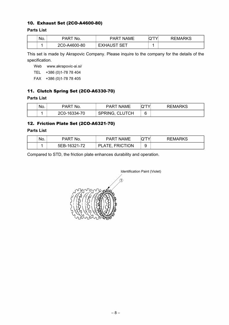
12. Friction Plate Set (2CO-A6321-70)
Compared to STD, the friction plate enhances durability and operation.
Parts List
No. PART No. PART NAME Q'TY REMARKS1 2C0-A4600-80 EXHAUST SET 1
Parts List
No. PART No. PART NAME Q'TY REMARKS1 2C0-16334-70 SPRING, CLUTCH 6
Parts List
No. PART No. PART NAME Q'TY REMARKS1 5EB-16321-72 PLATE, FRICTION 9
Identification Paint (Violet)
– 8 –

13. AIS Plug Set (5SL-A4890-70)This plug set is used when the AIS (Air Induction System), an exhaust gas purification system,is removed.
Installation1. Remove the hose attached to the cylinder head cover and the air cut-off valve assembly
accompanying the hose.2. Remove the cap fitted to the hose and remove the reed valve and plate from the inside.3. Install the plate (5SL-1482L-70) in replacement of the cap. Apply liquid gasket to the plate.4. Remove the cylinder head cover and the four collars fitted to the cover. Install the PIN
(93608-16M16).5. After removing the hose connected to the air cleaner case from the air-cut assembly, insert
the PLUG (90338-08026) onto the side of the air cleaner case to close the opening.
Parts List
No. PART No. PART NAME Q'TY REMARKS1 5SL-1482L-70 PLATE 2
* 2 93608-16M16 PIN 4* 3 90338-08026 PLUG 1
– 9 –

14. Transmission SetParts List
No. PART No. PART NAME Q'TY REMARKS
1-A 2C0-17411-80-A AXLE, MAIN 1 A
1-B 2C0-17411-90-B AXLE, MAIN 1 B
* 1-C 2C0-17411-00 AXLE, MAIN 1 C
* 2 90387-250R3 COLLAR 1
3-A 2C0-17151-71-A GEAR, 5TH PINION 1 A
3-B 2C0-17151-80-B GEAR, 5TH PINION 1 B
3-C 2C0-17151-90-C GEAR, 5TH PINION 1 C
* 4 90209-21332 WASHER 2
* 5 93440-25186 CIRCLIP 2
6-A 2C0-17131-80-A GEAR, 3RD PINION 1 A
6-B 2C0-17131-71-B GEAR, 3RD PINION 1 B
6-C 2C0-17131-90-C GEAR, 3RD PINION 1 C
* 7 90387-21003 COLLAR 1
8-A 2C0-17161-70-A GEAR, 6TH PINION 1 A
* 8-B 2C0-17161-00 GEAR, 6TH PINION 1 B
8-C 2C0-17161-90-C GEAR, 6TH PINION 1 C
* 9 90209-22352 WASHER 1
* 10 90209-21351 WASHER 1
11-A 2C0-17121-80-A GEAR, 2ND PINION 1 A
11-B 2C0-17121-90-B GEAR, 2ND PINION 1 B
* 11-C 2C0-17121-00 GEAR, 2ND PINION 1 C
* 12 2C0-15163-00 HSG., BEARING 1
* 13 93306-20562 BRG. 1
* 14 90151-06024 SCREW 3
* 15 93306-20464 BEARING 1
* 16 2C0-17421-00 AXLE, DRIVE 1
* 17 93305-20509 BEARING 1
* 18 90387-25016 COLLAR 1
* 19 90387-28011 COLLAR 1
20-A 2C0-17221-81-A GEAR, 2ND WHEEL 1 A
20-B 2C0-17221-90-B GEAR, 2ND WHEEL 1 B
* 20-C 2C0-17221-00 GEAR, 2ND WHEEL 1 C
* 21 90209-25011 WASHER 3
* 22 93440-28184 CIRCLIP 3
23-A 2C0-17261-71-A GEAR, 6TH WHEEL 1 A
23-B 2C0-17261-80-B GEAR, 6TH WHEEL 1 B
– 10 –
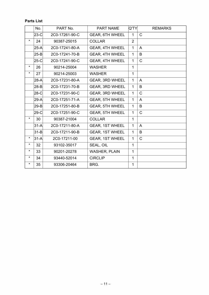
23-C 2C0-17261-90-C GEAR, 6TH WHEEL 1 C
* 24 90387-25015 COLLAR 2
25-A 2C0-17241-80-A GEAR, 4TH WHEEL 1 A
25-B 2C0-17241-70-B GEAR, 4TH WHEEL 1 B
25-C 2C0-17241-90-C GEAR, 4TH WHEEL 1 C
* 26 90214-25004 WASHER 1
* 27 90214-25003 WASHER 1
28-A 2C0-17231-80-A GEAR, 3RD WHEEL 1 A
28-B 2C0-17231-70-B GEAR, 3RD WHEEL 1 B
28-C 2C0-17231-90-C GEAR, 3RD WHEEL 1 C
29-A 2C0-17251-71-A GEAR, 5TH WHEEL 1 A
29-B 2C0-17251-80-B GEAR, 5TH WHEEL 1 B
29-C 2C0-17251-90-C GEAR, 5TH WHEEL 1 C
* 30 90387-21004 COLLAR 1
31-A 2C0-17211-80-A GEAR, 1ST WHEEL 1 A
31-B 2C0-17211-90-B GEAR, 1ST WHEEL 1 B
* 31-A 2C0-17211-00 GEAR, 1ST WHEEL 1 C
* 32 93102-35017 SEAL, OIL 1
* 33 90201-20278 WASHER, PLAIN 1
* 34 93440-52014 CIRCLIP 1
* 35 93306-20464 BRG. 1
Parts List
No. PART No. PART NAME Q'TY REMARKS
– 11 –
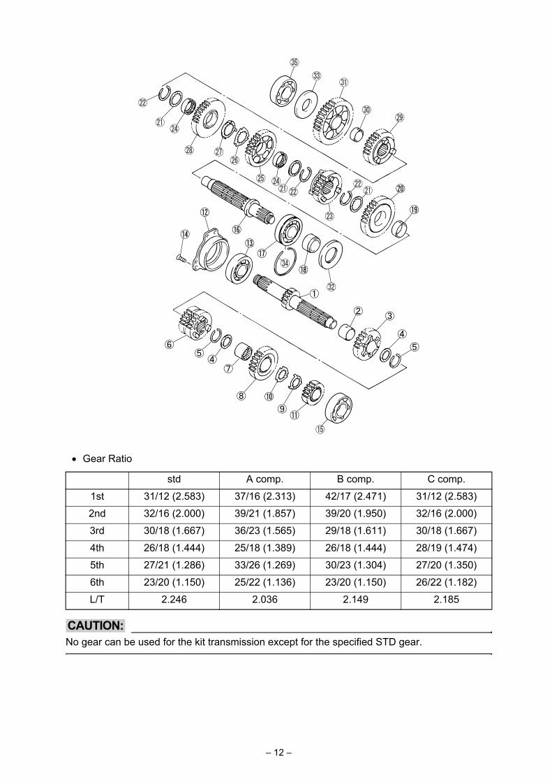
• Gear Ratio
CAUTION:No gear can be used for the kit transmission except for the specified STD gear.
std A comp. B comp. C comp.
1st 31/12 (2.583) 37/16 (2.313) 42/17 (2.471) 31/12 (2.583)
2nd 32/16 (2.000) 39/21 (1.857) 39/20 (1.950) 32/16 (2.000)
3rd 30/18 (1.667) 36/23 (1.565) 29/18 (1.611) 30/18 (1.667)
4th 26/18 (1.444) 25/18 (1.389) 26/18 (1.444) 28/19 (1.474)
5th 27/21 (1.286) 33/26 (1.269) 30/23 (1.304) 27/20 (1.350)
6th 23/20 (1.150) 25/22 (1.136) 23/20 (1.150) 26/22 (1.182)
L/T 2.246 2.036 2.149 2.185
– 12 –

15. Optional Gear SetYZF-R6 Mission ratio
Make sure that the pinion and wheel gear are combined for use according to the chart plan.
Pinion gear Wheel gear
GEAR PLAN Ratio Part number The numberof teeth
Stamp Part number The numberof teeth
Stamp
1ST A 2.313 2C0-17411-80-A 16 A 2C0-17211-80-A 37 A
B 2.471 2C0-17411-90-B 17 B 2C0-17211-90-B 42 B
C 2.583 2C0-17411-00 12 2C0-17211-00 31
2ND A 1.857 2C0-17121-80-A 21 A 2C0-17221-81-A 39 A
B 1.950 2C0-17121-90-B 20 B 2C0-17221-90-B 39 B
C 2.000 2C0-17121-00 16 2C0-17221-00 32
3RD A 1.565 2C0-17131-80-A 23 A 2C0-17231-80-A 36 A
B 1.611 2C0-17131-71-B 18 B 2C0-17231-70-B 29 B
C 1.667 2C0-17131-90-C 18 C 2C0-17231-90-C 30 C
4TH A 1.389 2C0-17131-80-A 18 A 2C0-17241-80-A 25 A
B 1.444 2C0-17131-71-B 18 B 2C0-17241-70-B 26 B
C 1.474 2C0-17131-90-C 19 C 2C0-17241-90-C 28 C
5TH A 1.269 2C0-17151-71-A 26 A 2C0-17251-71-A 33 A
B 1.304 2C0-17151-80-B 23 B 2C0-17251-80-B 30 B
C 1.350 2C0-17151-90-C 20 C 2C0-17251-90-C 27 C
6TH A 1.136 2C0-17161-70-A 22 A 2C0-17261-71-A 25 A
B 1.150 2C0-17161-00 20 2C0-17261-80-B 23 B
C 1.182 2C0-17161-90-C 22 C 2C0-17261-90-C 26 C
– 13 –

16. Drive Sprocket
These parts are for 520 chains (STD=525 chain).Use the nuts for the kit to mount the drive sprocket.
These sprockets are manufactured to be compatible with new and old models.
CAUTION:Take care not to install the sprocket in the wrong direction. If it is installed in the wrongdirection, it will cause the misalignment of the drive and rear sprockets, leading to the loss ofpower.
Parts List
No. PART No. PART NAME Q'TY REMARKS1 2C0-17460-74 SPROCKET, DRIVE 1 14T2 2C0-17460-75 SPROCKET, DRIVE 1 15T3 2C0-17460-76 SPROCKET, DRIVE 1 16T
GROOVE
MACHININGSTAMP OF THE NUMBER OF
TEETH ON BOTH SIDES
2CO ('06 and after YZF-R6)
Install with the grooved surface
facing outside of the chassis.
5SL ('05 and previous YZF-R6)
Install with the grooved surface
facing inside of the chassis.
– 14 –

17. Sprocket Nut Set (2C0-A7463-70)Parts List
No. PART No. PART NAME Q'TY REMARKS* 1 90179-20005 NUT, SPROCKET 1* 2 90215-21256 WASHER,
TONGUED1
– 15 –

18. ACM Set (2C0-F1400-71)
Caution on Assembly1. Remove grease from the taper surfaces of both rotor and crank before assembling them.2. Apply engine oil on the thread and flange of mounting bolts before using them.3. Apply Loctite® on the bolts before assembling stator coil to the cover.
Parts List
No. PART No. PART NAME Q'TY REMARKS1 2C0-81410-70 STATOR ASSY. 12 2C0-81450-70 ROTOR ASSY. 1
* 3 2C0-15580-00 STARTER CLUTCH ASSY.
1
* 4 2C0-15536-00 CLIP, STARTER 15 2C0-15411-71 COVER 1
* 6 90149-06080 SCREW 37 2C0-15451-70 GASKET 1
STDTightening torque70 Nm
Tightening torque12.0 Nm
Tightening torque
– 16 –

19. Wire Harness Set (2C0-F2590-80)
• The switches (2 types) supplied in this set enable the main switch and pit load limiter to beused. (See diagram 1.)
• Alternatively, the switch installed to STD machine may be used as is. (See diagram 2.)• When using the STD switch (left-side) , connect the wire sub lead supplied in this set to the
terminal leading to the horn to which the left-side switch is originally connected. (Seediagram 3.)
• Do not remove the AC generator but leave it to function. Use on the battery alone will makethe machine unable to run in a short time.
• Combination of this harness and kit ECU will enable the engine kill switch to function (cutignition). Install the switch to the 2-pin black coupler underneath the tank as required.Turning the switch ON cuts the ignition.
• Use the bracket regulator supplied in this kit when the regulator is installed at the locationshown in diagram 4 as in a case where the large-size radiator is installed from the kit.
Parts List
No. PART No. PART NAME Q'TY REMARKS
1 2C0-82590-80 HARNESS ASSY 1
2 5FL-83976-70 SWITCH ASSY. 1
* 3 5GF-83976-00 SW. HANDLE1 1
4 2C0-2128A-70 BRKT.,REGULATOR 1 1
5 2C0-82509-70 WIRE SUB-LEAD 1 1
Main switch
Pit loadlimiter
Kill switch
Starterswitch
(Diagram 1)
– 17 –

(Diagram 2)
Kill switch
Starterswitch
Pit loadlimiterON ONPUSH=OFF
Not used
ON OFF
Pit loadlimiter
*Use 5FL-83976-70 SWITCH ASSY supplied in this package as a main switch.
Not usedNot used
5
(Diagram 3)
4
(Diagram 4)
– 18 –

20. Engine Control Unit (ECU)
• Use of this set and a wire harness included in the kit enables regulation (or setting) of fuelinjection and ignition timing, etc.
• For details as to how to regulate (or set) fuel injection and ignition timings, etc., refer to themanual in the CD-ROM that comes with the set.
• There are two types of basic control data for the ECU included in this set: SS (SuperSports) and ST (Stock Sports). They can be switched over and vice versa. To make it in theST specification, just remove two couplers located at the lower left of the kit harness fueltank. (See the figure below.)<Setting-up Details>SS specification: Kit cam shaft and kit exhaust setST specification: Kit exhaust
CAUTION:Make sure to use the ECU in this set in combination with the kit wire harness. Otherwise, itdoesn't work.
Parts List
No. PART No. PART NAME Q'TY REMARKS1 2C0-8591A-70 ECU 12 CD 1 SOFT, MANUAL
– 19 –
21. Cable Interface (2C0-8533A-70)
• This cable connects the kit wire harness to the personal computer on which YEC FIMatching System (YMS) is installed.
• Please see the YMS manual for instructions on how to use YMS.
Parts List
No. PART No. PART NAME Q'TY REMARKS1 2CO-8533A-70 CABLE, INTERFACE 1
– 20 –

• Use of the ECU in the kit and the harness allows functioning of the following codes in theSTD diagnosis.* YMS-Monitor: YEC FI Matching System also allows functioning of the code shown below.
<Diagnosis Functions>
CODE Contents *YMS-Monitor01 Throttle sensor TPS 1(deg)02 Atmospheric pressure sensor Atmospheric (kPa)03 Intake pressure sensor 1 Intake Air (kPa)05 Intake temperature sensor Air Temp. (°C)06 Water temperature sensor Water Temp. (°C)07 Vehicle speed sensor Speed Signal (--)08 Overturn sensor Lean Angle Signal
(V)09 Monitor voltage System Voltage (V)13 Throttle sensor 2 TPS 2 (deg)14 Accelerator sensor 1 APS 1 (deg)15 Accelerator sensor 2 APS 2 (deg)21 Neutral switch Neutral SW30 Ignition coil #1 —31 Ignition coil #2 —32 Ignition coil #3 —33 Ignition coil #4 —36 Injector (primary) #1 —37 Injector (primary) #2 —38 Injector (primary) #3 —39 Injector (primary) #4 —40 Injector (secondary) #1 —41 Injector (secondary) #2 —42 Injector (secondary) #3 —43 Injector (secondary) #4 —50 Main relay —70 Program version —
– 21 –

Self-Diagnosis Functions• The ECU and harness in the kit provide the functions for the following codes of standard
self-diagnosis:
CODE Description
00 All functions normally.
11 Cam angle sensor malfunctions.
12 Crank angle sensor malfunctions.
13 Intake pressure sensor malfunctions (open circuit / short circuit).
14 Intake pressure sensor malfunctions (piping system).
15 Throttle opening sensor malfunctions (open circuit / short circuit / ETV).
20 Intake pressure sensor or atmospheric pressure sensor malfunctions.
21 Water temperature sensor malfunctions (open circuit / short circuit).
22 Intake temperature sensor malfunctions (open circuit / short circuit).
23 Atmospheric pressure sensor malfunctions (open circuit / short circuit).
33 Ignition coil #1 malfunctions (open circuit).
34 Ignition coil #2 malfunctions (open circuit).
35 Ignition coil #3 malfunctions (open circuit).
36 Ignition coil #4 malfunctions (open circuit).
39 Injector (primary) malfunctions (open circuit).
40 Injector (secondary) malfunctions (open circuit).
43 Battery voltage monitor malfunctions (power source for fuel system).
46 Power source for vehicle malfunctions.
59 Accelerator opening sensor malfunctions (open circuit / short circuit).
60 Throttle motor malfunctions (drive system).
– 22 –
22. 2D Data Logger
These data logging sets are made by 2D Debus & Diebold Meßsysteme GmbH.The 2D basic sets include a connector that allows one-touch connection of the set with the kitwire harness.No stay is set for sensor installation.For how to use the 2D basic sets, refer to the manual comes with the sets.For the details, refer to 2D Debus & Diebold Meßsysteme GmbH.
Web www.2d-datarecording.com/Tel +49 (0) 721 944850Fax +49 (0) 721 9448529
Parts List
No. PART No. PART NAME Q'TY REMARKS1 4C8-F37L0-2D 2D BASIC SET 12 5VY-F37T0-2D TRANSMITTER UNIT
SET1
3 4C8-F37D0-2D BLG DIGITAL DASH BOARD
1
4 4C8-F37M0-2D MEMORY UNIT SET 15 5VY-F37S0-2D SUSPENSION SENSOR
SET1
6 5VY-F37G0-2D GPS SENSOR SET 1
– 23 –

23. Engine Protector Set (2C0-A5491-70)
These parts protect the chassis as well as alleviating damage caused by overturning.
Parts List
No. PART No. PART NAME Q'TY REMARKS1 2C0-15491-70 PROTECTOR 1
* 2 91314-06025 BOLT 2* 3 91314-06020 BOLT 1
– 24 –

24. Chassis Protector SetParts List
No. PART No. PART NAME Q'TY REMARKS1 2C0-2117G-70 PROTECTOR(LH LONG) 12 2C0-2117G-90 PROTECTOR(RH SHORT) 13 2C0-21472-70 COLLAR PROTECTOR 2
* 4 91317-10060 BOLT SOCKET HEAD M10L60(LH)
1
* 5 91314-10065 BOLT SOCKET HEAD M10L65(RH)
1
* 6 90201-10136 WASHER 2
Tightening torque40 Nm (4.0 m•kg)
Tightening torque40 Nm (4.0 m•kg)
Tightening torque
FWD
ENGINE
– 25 –

Before mounting the protector, cut the cowling so that the protector can fit against the chassis.As a rough guide, cut by φ60 centered on the engine mount. See the figures below.
– 26 –
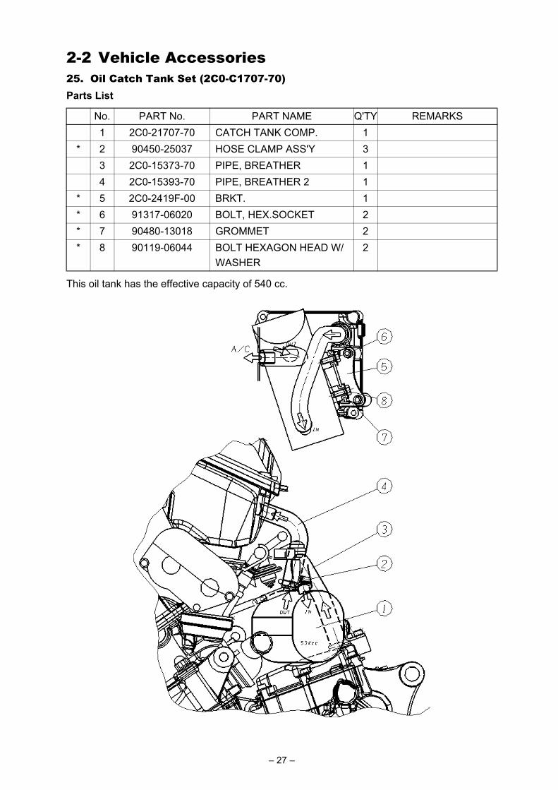
2-2 Vehicle Accessories25. Oil Catch Tank Set (2C0-C1707-70)
This oil tank has the effective capacity of 540 cc.
Parts List
No. PART No. PART NAME Q'TY REMARKS1 2C0-21707-70 CATCH TANK COMP. 1
* 2 90450-25037 HOSE CLAMP ASS'Y 33 2C0-15373-70 PIPE, BREATHER 14 2C0-15393-70 PIPE, BREATHER 2 1
* 5 2C0-2419F-00 BRKT. 1* 6 91317-06020 BOLT, HEX.SOCKET 2* 7 90480-13018 GROMMET 2* 8 90119-06044 BOLT HEXAGON HEAD W/
WASHER2
– 27 –
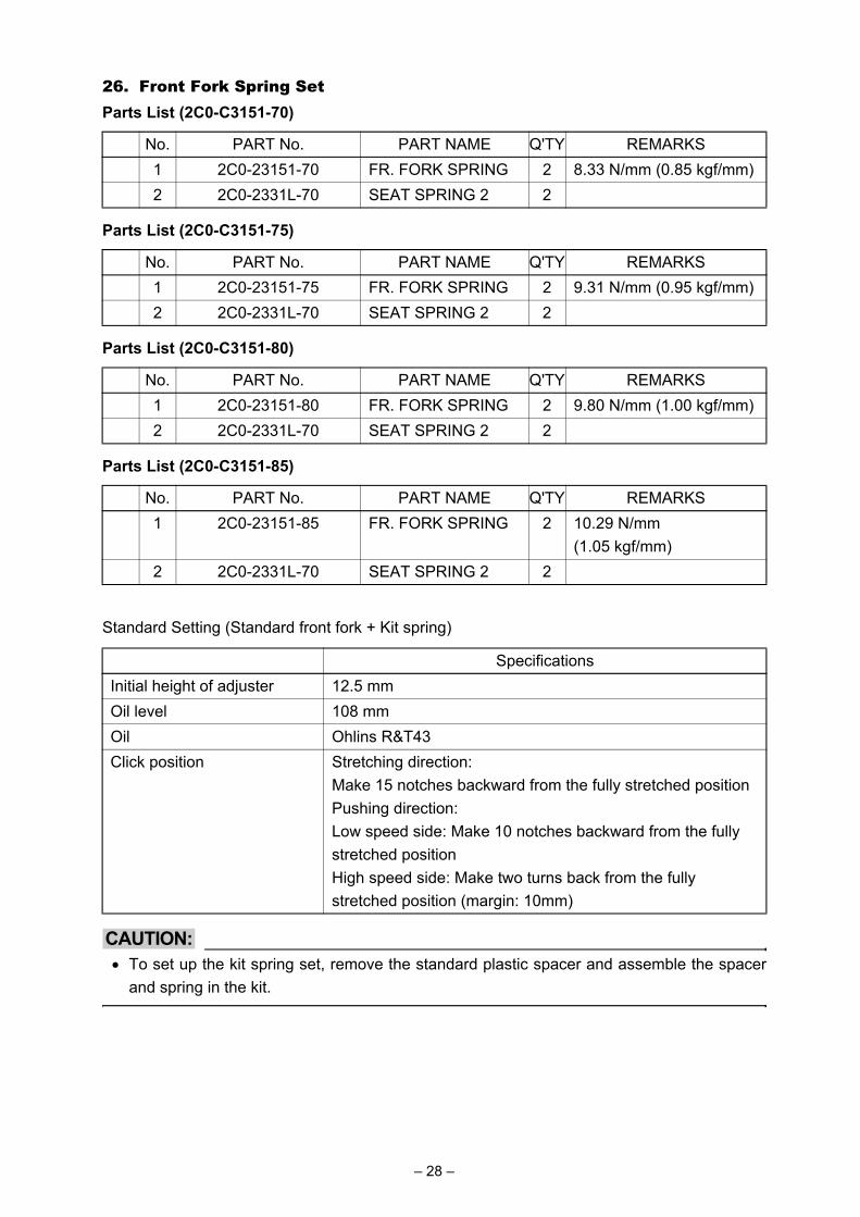
26. Front Fork Spring Set
Standard Setting (Standard front fork + Kit spring)
CAUTION:• To set up the kit spring set, remove the standard plastic spacer and assemble the spacer
and spring in the kit.
Parts List (2C0-C3151-70)
No. PART No. PART NAME Q'TY REMARKS1 2C0-23151-70 FR. FORK SPRING 2 8.33 N/mm (0.85 kgf/mm)2 2C0-2331L-70 SEAT SPRING 2 2
Parts List (2C0-C3151-75)
No. PART No. PART NAME Q'TY REMARKS1 2C0-23151-75 FR. FORK SPRING 2 9.31 N/mm (0.95 kgf/mm)2 2C0-2331L-70 SEAT SPRING 2 2
Parts List (2C0-C3151-80)
No. PART No. PART NAME Q'TY REMARKS1 2C0-23151-80 FR. FORK SPRING 2 9.80 N/mm (1.00 kgf/mm)2 2C0-2331L-70 SEAT SPRING 2 2
Parts List (2C0-C3151-85)
No. PART No. PART NAME Q'TY REMARKS1 2C0-23151-85 FR. FORK SPRING 2 10.29 N/mm
(1.05 kgf/mm)2 2C0-2331L-70 SEAT SPRING 2 2
SpecificationsInitial height of adjuster 12.5 mmOil level 108 mmOil Ohlins R&T43Click position Stretching direction:
Make 15 notches backward from the fully stretched positionPushing direction:Low speed side: Make 10 notches backward from the fully stretched positionHigh speed side: Make two turns back from the fully stretched position (margin: 10mm)
– 28 –
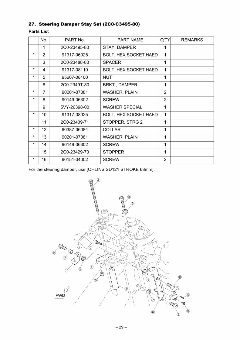
27. Steering Damper Stay Set (2C0-C3495-80)
For the steering damper, use [OHLINS SD121 STROKE 68mm].
Parts List
No. PART No. PART NAME Q'TY REMARKS
1 2C0-23495-80 STAY, DAMPER 1
* 2 91317-06025 BOLT, HEX.SOCKET HAED 1
3 2C0-23488-80 SPACER 1
* 4 91317-08110 BOLT, HEX.SOCKET HAED 1
* 5 95607-08100 NUT 1
6 2C0-2349T-80 BRKT., DAMPER 1
* 7 90201-07081 WASHER, PLAIN 2
* 8 90149-06302 SCREW 2
9 5VY-26398-00 WASHER SPECIAL 1
* 10 91317-08025 BOLT, HEX.SOCKET HAED 1
11 2C0-23439-71 STOPPER, STRG 2 1
* 12 90387-06084 COLLAR 1
* 13 90201-07081 WASHER, PLAIN 1
* 14 90149-06302 SCREW 1
15 2C0-23429-70 STOPPER 1
* 16 90151-04002 SCREW 2
– 29 –
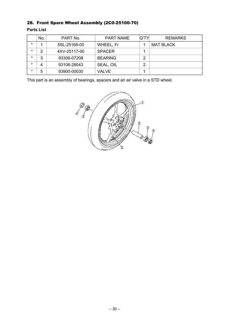
28. Front Spare Wheel Assembly (2C0-25100-70)
This part is an assembly of bearings, spacers and an air valve in a STD wheel.
Parts List
No. PART No. PART NAME Q'TY REMARKS* 1 5SL-25168-00 WHEEL, Fr 1 MAT BLACK* 2 4XV-25117-00 SPACER 1* 3 93306-07208 BEARING 2* 4 93106-28043 SEAL, OIL 2* 5 93900-00030 VALVE 1
– 30 –

29. Rear Spare Wheel Assembly (2C0-25300-70)
This part is an assembly of bearings, spacers and an air valve in a STD wheel.
Parts List
No. PART No. PART NAME Q'TY REMARKS* 1 5SL-25338-00 WHEEL, Rr 1 MAT BLACK* 2 93306-20531 BEARING 1* 3 93106-40013 SEAL, OIL 1* 4 93317-43580 BEARING 1* 5 93420-61M07 CIRCLIP 1* 6 4XV-25317-00 SPACER 1* 7 5SL-25383-00 COLLAR 1* 8 93900-00030 VALVE 1
– 31 –
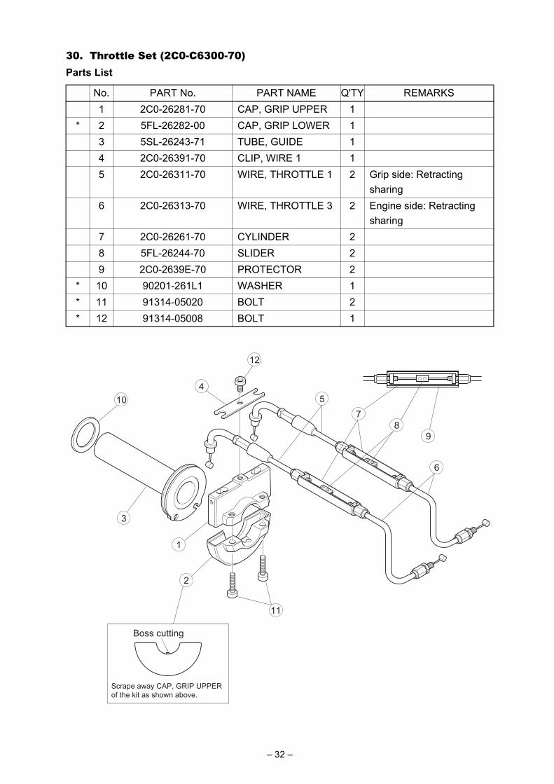
30. Throttle Set (2C0-C6300-70)Parts List
No. PART No. PART NAME Q'TY REMARKS1 2C0-26281-70 CAP, GRIP UPPER 1
* 2 5FL-26282-00 CAP, GRIP LOWER 13 5SL-26243-71 TUBE, GUIDE 14 2C0-26391-70 CLIP, WIRE 1 15 2C0-26311-70 WIRE, THROTTLE 1 2 Grip side: Retracting
sharing6 2C0-26313-70 WIRE, THROTTLE 3 2 Engine side: Retracting
sharing7 2C0-26261-70 CYLINDER 28 5FL-26244-70 SLIDER 29 2C0-2639E-70 PROTECTOR 2
* 10 90201-261L1 WASHER 1* 11 91314-05020 BOLT 2* 12 91314-05008 BOLT 1
2
1
Boss cutting
Scrape away CAP, GRIP UPPER
of the kit as shown above.
3
5
6
7
89
10
11
12
4
– 32 –
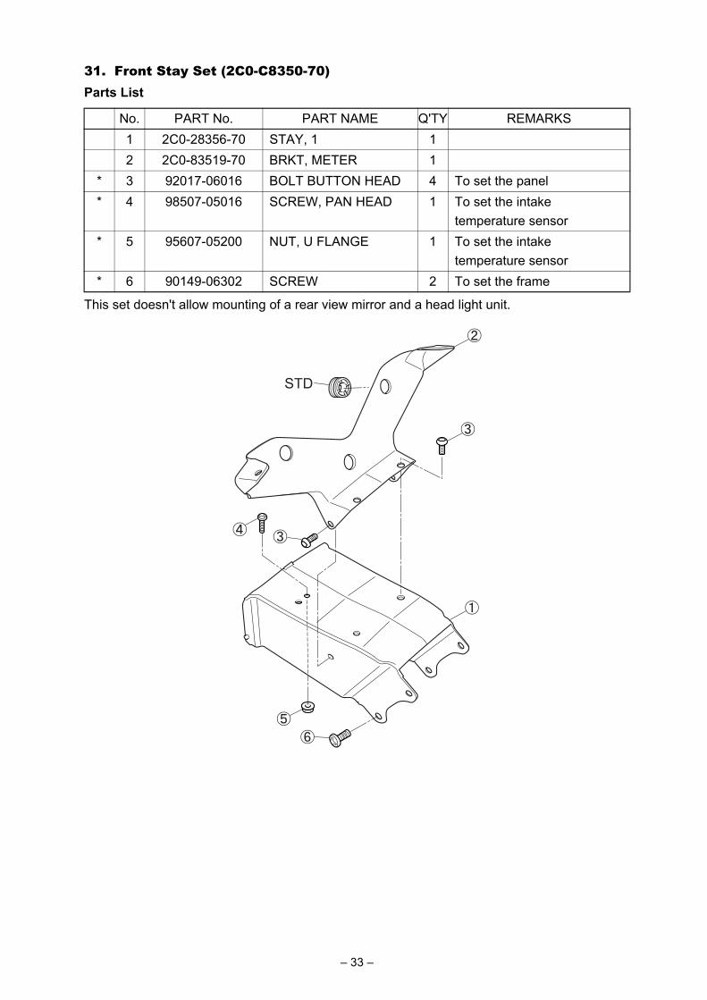
31. Front Stay Set (2C0-C8350-70)
This set doesn't allow mounting of a rear view mirror and a head light unit.
Parts List
No. PART No. PART NAME Q'TY REMARKS1 2C0-28356-70 STAY, 1 12 2C0-83519-70 BRKT, METER 1
* 3 92017-06016 BOLT BUTTON HEAD 4 To set the panel* 4 98507-05016 SCREW, PAN HEAD 1 To set the intake
temperature sensor* 5 95607-05200 NUT, U FLANGE 1 To set the intake
temperature sensor* 6 90149-06302 SCREW 2 To set the frame
STD
– 33 –
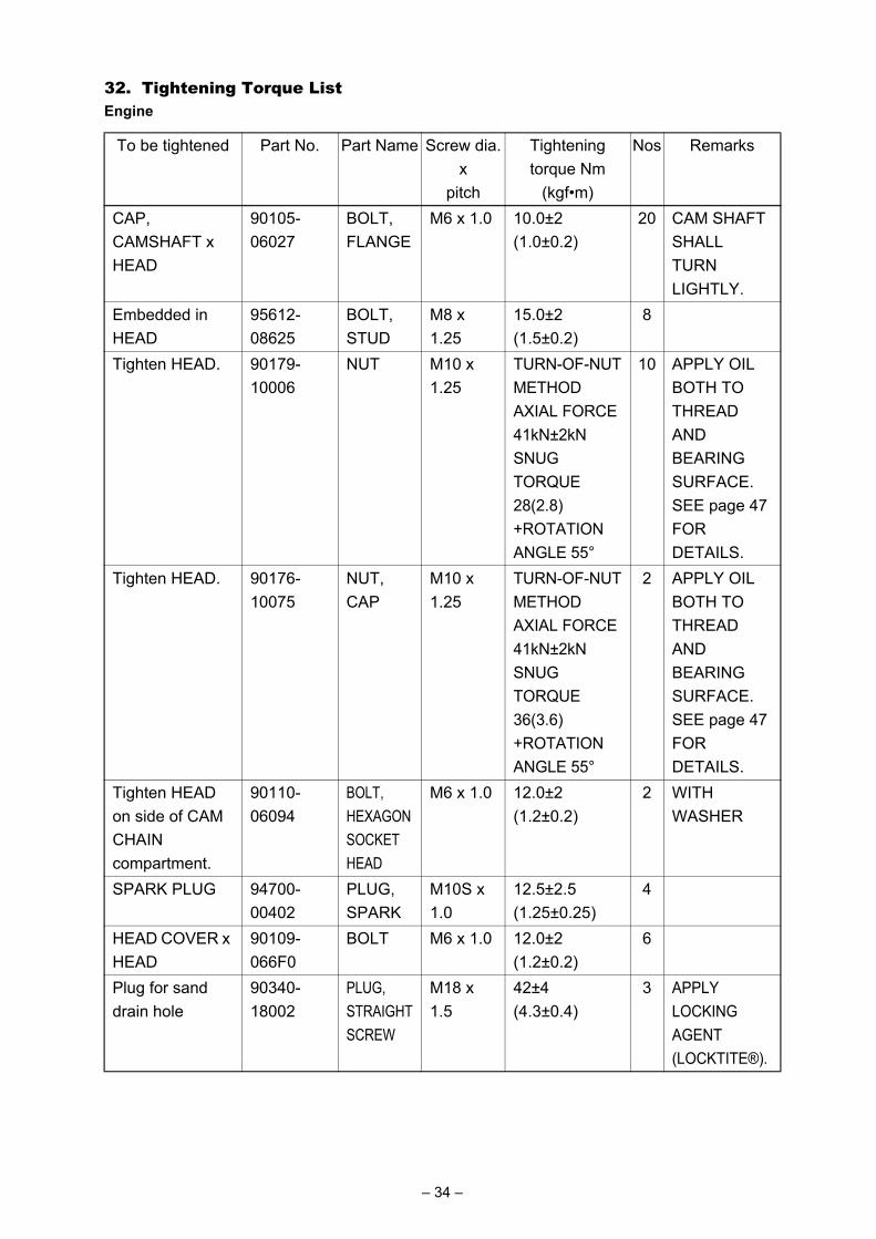
32. Tightening Torque ListEngine
To be tightened Part No. Part Name Screw dia.x
pitch
Tighteningtorque Nm
(kgf•m)
Nos Remarks
CAP, CAMSHAFT x HEAD
90105-06027
BOLT, FLANGE
M6 x 1.0 10.0±2(1.0±0.2)
20 CAM SHAFT SHALL TURN LIGHTLY.
Embedded in HEAD
95612-08625
BOLT, STUD
M8 x 1.25
15.0±2(1.5±0.2)
8
Tighten HEAD. 90179-10006
NUT M10 x 1.25
TURN-OF-NUT METHOD AXIAL FORCE 41kN±2kN SNUG TORQUE 28(2.8) +ROTATION ANGLE 55°
10 APPLY OIL BOTH TO THREAD AND BEARING SURFACE. SEE page 47 FOR DETAILS.
Tighten HEAD. 90176-10075
NUT, CAP
M10 x 1.25
TURN-OF-NUT METHOD AXIAL FORCE 41kN±2kN SNUG TORQUE 36(3.6) +ROTATION ANGLE 55°
2 APPLY OIL BOTH TO THREAD AND BEARING SURFACE. SEE page 47 FOR DETAILS.
Tighten HEAD on side of CAM CHAIN compartment.
90110-06094
BOLT, HEXAGON SOCKET HEAD
M6 x 1.0 12.0±2(1.2±0.2)
2 WITH WASHER
SPARK PLUG 94700-00402
PLUG, SPARK
M10S x 1.0
12.5±2.5(1.25±0.25)
4
HEAD COVER x HEAD
90109-066F0
BOLT M6 x 1.0 12.0±2(1.2±0.2)
6
Plug for sand drain hole
90340-18002
PLUG, STRAIGHT SCREW
M18 x 1.5
42±4(4.3±0.4)
3 APPLY LOCKING AGENT (LOCKTITE®).
– 34 –
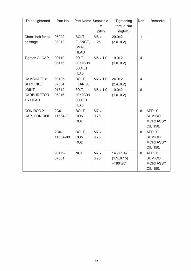
Check bolt for oil passage
95022-08012
BOLT, FLANGE, SMALL HEAD
M8 x 1.25
20.0±2(2.0±0.2)
1
Tighten AI CAP. 90110-06175
BOLT HEXAGON SOCKET HEAD
M6 x 1.0 10.0±2(1.0±0.2)
4
CAMSHAFT x SPROCKET
90105-07004
BOLT, FLANGE
M7 x 1.0 24.0±2(2.4±0.2)
4
JOINT, CARBURETOR1 x HEAD
91312-06016
BOLT, HEXAGON SOCKET HEAD
M6 x 1.0 10.0±2(1.0±0.2)
8
CON ROD X CAP, CON ROD
2C0-11654-00
BOLT, CON ROD
M7 x 0.75
8 APPLY SUMICO MORI ASSY OIL 150.
2C0-1165A-00
BOLT, CON ROD
M7 x 0.75
8 APPLY SUMICO MORI ASSY OIL 150.
90179-07001
NUT M7 x 0.75
14.7±1.47(1.5±0.15) +180°±5°
8 APPLY SUMICO MORI ASSY OIL 150.
To be tightened Part No. Part Name Screw dia.x
pitch
Tighteningtorque Nm
(kgf•m)
Nos Remarks
– 35 –

ACM ROTOR x CRANKSHAFT
90105-126A8
BOLT M12 x 1.25
70±5(7.0±0.5)
1 DEGREASE TAPERED SURFACE. APPLY OIL BOTH TO BOLT BEARING SURFACE AND THREAD AND TO BOTH SIDES OF WASHER. USE MORI-COATED WASHER.
TENSIONER ASSY x CYLINDER
90110-06106
BOLT, HEXAGON SOCKET HEAD
M6 x 1.0 12.0±2(1.2±0.2)
2 INSTALL TENSIONER ASSY.
Install COVER, THERMOSTAT.
91312-06020
BOLT, HEXAGON SOCKET HEAD
M6 x 1.0 12.0±2(1.2±0.2)
2
Install JOINT. 90105-06082
BOLT, FLANGE, SMALL HEAD
M6 x 1.0 10.0±2(1.0±0.2)
2
Install WATER PUMP.
90110-06140
BOLT, HEXAGON SOCKET HEAD
M6 x 1.0 12.0±2(1.2±0.2)
2
OIL PUMP ASSY x CRANKCASE 2
95812-06030
BOLT, FLANGE
M6 x 1.0 12.0±2(1.2±0.2)
2
OIL PUMP ASSY x CRANKCASE 2
95812-06080
BOLT, FLANGE
M6 x 1.0 12.0±2(1.2±0.2)
1
To be tightened Part No. Part Name Screw dia.x
pitch
Tighteningtorque Nm
(kgf•m)
Nos Remarks
– 36 –
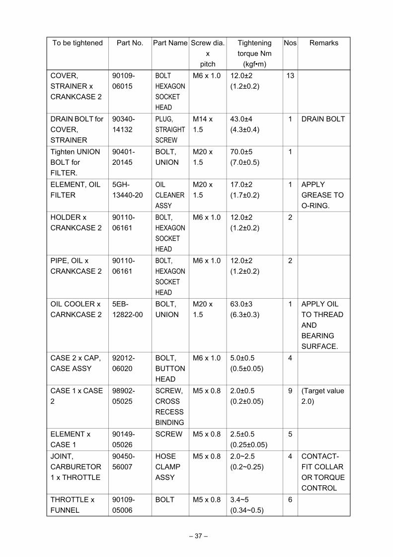
COVER, STRAINER x CRANKCASE 2
90109-06015
BOLT HEXAGON SOCKET HEAD
M6 x 1.0 12.0±2(1.2±0.2)
13
DRAIN BOLT for COVER, STRAINER
90340-14132
PLUG, STRAIGHT SCREW
M14 x 1.5
43.0±4(4.3±0.4)
1 DRAIN BOLT
Tighten UNION BOLT for FILTER.
90401-20145
BOLT, UNION
M20 x 1.5
70.0±5(7.0±0.5)
1
ELEMENT, OIL FILTER
5GH-13440-20
OIL CLEANER ASSY
M20 x 1.5
17.0±2(1.7±0.2)
1 APPLY GREASE TO O-RING.
HOLDER x CRANKCASE 2
90110-06161
BOLT, HEXAGON SOCKET HEAD
M6 x 1.0 12.0±2(1.2±0.2)
2
PIPE, OIL x CRANKCASE 2
90110-06161
BOLT, HEXAGON SOCKET HEAD
M6 x 1.0 12.0±2(1.2±0.2)
2
OIL COOLER x CARNKCASE 2
5EB-12822-00
BOLT, UNION
M20 x 1.5
63.0±3(6.3±0.3)
1 APPLY OIL TO THREAD AND BEARING SURFACE.
CASE 2 x CAP, CASE ASSY
92012-06020
BOLT, BUTTON HEAD
M6 x 1.0 5.0±0.5(0.5±0.05)
4
CASE 1 x CASE 2
98902-05025
SCREW, CROSS RECESS BINDING
M5 x 0.8 2.0±0.5(0.2±0.05)
9 (Target value 2.0)
ELEMENT x CASE 1
90149-05026
SCREW M5 x 0.8 2.5±0.5(0.25±0.05)
5
JOINT, CARBURETOR 1 x THROTTLE
90450-56007
HOSE CLAMP ASSY
M5 x 0.8 2.0~2.5(0.2~0.25)
4 CONTACT-FIT COLLAR OR TORQUE CONTROL
THROTTLE x FUNNEL
90109-05006
BOLT M5 x 0.8 3.4~5(0.34~0.5)
6
To be tightened Part No. Part Name Screw dia.x
pitch
Tighteningtorque Nm
(kgf•m)
Nos Remarks
– 37 –
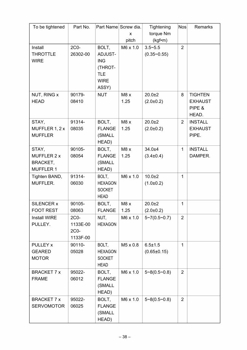
Install THROTTLE WIRE
2C0-26302-00
BOLT, ADJUST-ING(THROT-TLE WIRE ASSY)
M6 x 1.0 3.5~5.5(0.35~0.55)
2
NUT, RING x HEAD
90179-08410
NUT M8 x 1.25
20.0±2(2.0±0.2)
8 TIGHTEN EXHAUST PIPE & HEAD.
STAY, MUFFLER 1, 2 x MUFFLER
91314-08035
BOLT, FLANGE (SMALL HEAD)
M8 x 1.25
20.0±2(2.0±0.2)
2 INSTALL EXHAUST PIPE.
STAY, MUFFLER 2 x BRACKET, MUFFLER 1
90105-08054
BOLT, FLANGE (SMALL HEAD)
M8 x 1.25
34.0±4(3.4±0.4)
1 INSTALL DAMPER.
Tighten BAND, MUFFLER.
91314-06030
BOLT, HEXAGON SOCKET HEAD
M6 x 1.0 10.0±2(1.0±0.2)
1
SILENCER x FOOT REST
90105-08063
BOLT, FLANGE
M8 x 1.25
20.0±2(2.0±0.2)
1
Install WIRE PULLEY.
2C0-1133E-00 2C0-1133F-00
NUT, HEXAGON
M6 x 1.0 5~7(0.5~0.7) 2
PULLEY x GEARED MOTOR
90110-05028
BOLT, HEXAGON SOCKET HEAD
M5 x 0.8 6.5±1.5(0.65±0.15)
1
BRACKET 7 x FRAME
95022-06012
BOLT, FLANGE (SMALL HEAD)
M6 x 1.0 5~8(0.5~0.8) 2
BRACKET 7 x SERVOMOTOR
95022-06025
BOLT, FLANGE (SMALL HEAD)
M6 x 1.0 5~8(0.5~0.8) 2
To be tightened Part No. Part Name Screw dia.x
pitch
Tighteningtorque Nm
(kgf•m)
Nos Remarks
– 38 –

Install MUFFLER PROTECTOR.
90111-06071
BOLT, HEXAGON SOCKET BUTTON
M6 x 1.0 8.0±1.5(0.8±0.15)
1
Install MUFFLER PROTECTOR.
90111-06010
BOLT, HEXAGON SOCKET BUTTON
M6 x 1.0 6.5±1.5(0.65±0.15)
2
EXHAUST VALVE SUBASSY
90179-06M28
NUT M6 x 1.0 6.5±1.5(0.65±0.15)
1
CRANKCASE 1 x CRANKCASE 2
90119-08083
BOLT, FLANGE
M8 x 1.25
See page 48 for details.
8 APPLY OIL BOTH TO THREAD AND TO BEARING SURFACE.
CRANKCASE 1 x CRANKCASE 2
90119-08084
BOLT, FLANGE
M8 x 1.25
See page 48 for details.
2 APPLY OIL BOTH TO THREAD AND TO BEARING SURFACE.
CRANKCASE 1 x CRANKCASE 2
90109-06100
BOLT, FLANGE
M6 x 1.0 10.0±2(1.0±0.2)
2 APPLY OIL BOTH TO THREAD AND TO BEARING SURFACE.
CRANKCASE 1 x CRANKCASE 2
95812-06055
BOLT, FLANGE
M6 x 1.0 10.0±2(1.0±0.2)
7 APPLY OIL BOTH TO THREAD AND TO BEARING SURFACE.
CRANKCASE 1 x CRANKCASE 2
95812-08065
BOLT, FLANGE
M8 x 1.25
24±2(2.4±0.2)
2 APPLY OIL BOTH TO THREAD AND TO BEARING SURFACE.
To be tightened Part No. Part Name Screw dia.x
pitch
Tighteningtorque Nm
(kgf•m)
Nos Remarks
– 39 –

CRANKCASE 1 x CRANKCASE 2
95812-06065
BOLT, FLANGE
M6 x 1.0 10.0±2(1.0±0.2)
3 APPLY OIL BOTH TO THREAD AND TO BEARING SURFACE.
CRANKCASE 1 x CRANKCASE 2
95812-06045
BOLT, FLANGE
M6 x 1.0 10.0±2(1.0±0.2)
3 APPLY OIL BOTH TO THREAD AND TO BEARING SURFACE.
CRANKCASE 1 x CRANKCASE 2
95812-06030
BOLT, FLANGE
M6 x 1.0 10.0±2(1.0±0.2)
1 APPLY OIL BOTH TO THREAD AND TO BEARING SURFACE.
Install COVER, CRANKCASE 1.
90109-06015
BOLT M6 x 1.0 12.0±2(1.2±0.2)
9
Install COVER, CRANKCASE 2.
90109-06031
BOLT M6 x 1.0 12.0±2(1.2±0.2)
7
Install COVER, CRANKCASE 2.
90110-06156
BOLT HEXAGON SOCKET HEAD
M6 x 1.0 12.0±2(1.2±0.2)
2
Install COVER 1.
90109-06014
BOLT M6 x 1.0 12.0±2(1.2±0.2)
5
COVER 1 x HOLDER, CLUTCH
90109-06015
BOLT M6 x 1.0 12.0±2(1.2±0.2)
2
COVER 1 x BOLT
92014-08014
BOLT, BUTTON HEAD
M8 x 1.25
15.0±2(1.5±0.2)
1
COVER 1 x PLUG, STRAIGHT
90340-32004
PLUG, STRAIGHT SCREW
M32 x 1.5
CLOSE CONTACT WITH BEARING SURFACE
1
To be tightened Part No. Part Name Screw dia.x
pitch
Tighteningtorque Nm
(kgf•m)
Nos Remarks
– 40 –

PLATE, BREATHER x C/C1
90149-06082
SCREW M6 x 1.0 12.0±2(1.2±0.2)
3
COVER, CRANKCASE 1 x STATOR ASSY
90149-06080
SCREW M6 x 1.0 10.0±2(1.0±0.2)
3
PLUG WITH COMMUNICATION HOLE x CRANKCASE 1
90149-06082
SCREW M6 x 1.0 12.0±2(1.2±0.2)
1
Install COVER, CHAIN CASE.
90110-06060
BOLT M6 x 1.0 10.0±2(1.0±0.2)
3
Install M GALLERY PLUG.
36Y-15189-00
PLUG M16 x 1.5
8.0±2(0.8±0.2)
2 TAKE CARE NOT TO OVERTIGHTEN
COVER, CRANKCASE 1 x CLAMP
90149-06082
SCREW M6 x 1.0 10.0±2(1.0±0.2)
1 STATOR LEAD
Install COVER. 90109-06015
BOLT, HEXAGON SOCKET HEAD
M6 x 1.0 12.0±2(1.2±0.2)
5
Install OIL PIPE (OUTSIDE)
90110-06161
BOLT, HEXAGON SOCKET HEAD
M6 x 1.0 12.0±2(1.2±0.2)
2
CRANKCASE 2 x PICKUP
90110-06168
BOLT, HEXAGON SOCKET HEAD
M6 x 1.0 10.0±2(1.0±0.2)
2
Embedded in CRANKCASE x STUD, EMBEDDED
90116-1002*
BOLT, STUD
M10 x 1.25
(HEIGHT 68.2±1)
10
Install PRESSURE PLATE.
90159-06024
SCREW, W/W
M6 x 1.0 8.0±2(0.8±0.2)
6
To be tightened Part No. Part Name Screw dia.x
pitch
Tighteningtorque Nm
(kgf•m)
Nos Remarks
– 41 –

BOSS, CLUTCH x MAIN AXLE
2C0-16377-00
NUT, LOCK
M20 x 1.0
115.0±5(11.5±0.5)
1 CRIMP AND APPLY OIL BOTH TO THREAD AND BEARING SURFACE.
BOSS, PRESSURE PLATE x BOLT, STUD
2C0-16374-00
BOLT, STUD
M8 x 1.25
25.0±2(2.5±0.2)
6
Install SPROCKET, DRIVE.
90179-20011
NUT M20 x 1.0
85.0±5(8.5±0.5)
1 NO OIL SHALL BE STUCK. CRIMP.
HOUSING, BEARING
90151-06024
SCREW M6 x 1.0 12.0±2(1.2±0.2)
3 CRIMP.
Install STOPPER, SHAFT BAR.
90110-06182
BOLT, HEXAGON
M6 x 1.0 10.0±2(1.0±0.2)
2
STOPPER embedded in CRANKCASE
1D7-18127-00
STOPPER, SCREW
M8 x 1.25
22.0±2(2.2±0.2)
1
Install ARM, SHIFT.
95822-06020
BOLT, FLANGE
M6 x 1.0 10.0±2(1.0±0.2)
1 CHECK FOR SERRATION TIGHTENING UP.
Install ROTOR, PICKUP.
90105-08113
BOLT, FLANGE
M8 x 1.25
35.0±5(3.5±0.5)
1
Install STARTER MOTOR.
90105-06083
BOLT, FLANGE (SMALL HEAD)
M6 x 1.0 10.0±2(1.0±0.2)
2
NEUTRAL SWITCH ASSY
3GB-82540-01
NEUTRAL S/W ASSY
M10 x 1.25
19.6±2(2.0±0.2)
1 OVERTIGHT-ENING LEADS TO DAMAGE.
Install OIL LEVEL SENSOR.
95022-06016
BOLT, FLANGE (SMALL HEAD)
M6 x 1.0 10.0±2(1.0±0.2)
2 APPLY GREASE TO O-RING.
To be tightened Part No. Part Name Screw dia.x
pitch
Tighteningtorque Nm
(kgf•m)
Nos Remarks
– 42 –
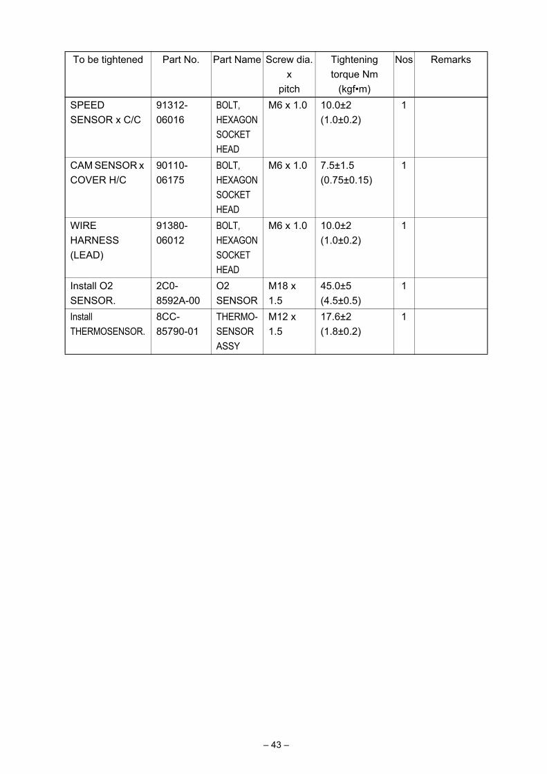
SPEED SENSOR x C/C
91312-06016
BOLT, HEXAGON SOCKET HEAD
M6 x 1.0 10.0±2(1.0±0.2)
1
CAM SENSOR x COVER H/C
90110-06175
BOLT, HEXAGON SOCKET HEAD
M6 x 1.0 7.5±1.5(0.75±0.15)
1
WIRE HARNESS (LEAD)
91380-06012
BOLT, HEXAGON SOCKET HEAD
M6 x 1.0 10.0±2(1.0±0.2)
1
Install O2 SENSOR.
2C0-8592A-00
O2 SENSOR
M18 x 1.5
45.0±5(4.5±0.5)
1
Install THERMOSENSOR.
8CC-85790-01
THERMO-SENSOR ASSY
M12 x 1.5
17.6±2(1.8±0.2)
1
To be tightened Part No. Part Name Screw dia.x
pitch
Tighteningtorque Nm
(kgf•m)
Nos Remarks
– 43 –
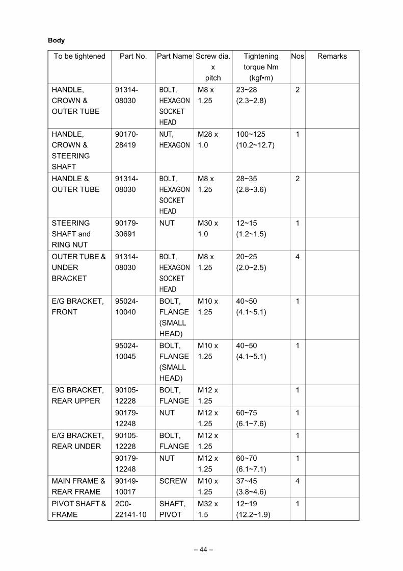
Body
To be tightened Part No. Part Name Screw dia.x
pitch
Tightening torque Nm
(kgf•m)
Nos Remarks
HANDLE, CROWN & OUTER TUBE
91314-08030
BOLT, HEXAGON SOCKET HEAD
M8 x 1.25
23~28(2.3~2.8)
2
HANDLE, CROWN & STEERING SHAFT
90170-28419
NUT, HEXAGON
M28 x 1.0
100~125(10.2~12.7)
1
HANDLE & OUTER TUBE
91314-08030
BOLT, HEXAGON SOCKET HEAD
M8 x 1.25
28~35(2.8~3.6)
2
STEERING SHAFT and RING NUT
90179-30691
NUT M30 x 1.0
12~15(1.2~1.5)
1
OUTER TUBE & UNDER BRACKET
91314-08030
BOLT, HEXAGON SOCKET HEAD
M8 x 1.25
20~25(2.0~2.5)
4
E/G BRACKET, FRONT
95024-10040
BOLT, FLANGE (SMALL HEAD)
M10 x 1.25
40~50(4.1~5.1)
1
95024-10045
BOLT, FLANGE (SMALL HEAD)
M10 x 1.25
40~50(4.1~5.1)
1
E/G BRACKET, REAR UPPER
90105-12228
BOLT, FLANGE
M12 x 1.25
1
90179-12248
NUT M12 x 1.25
60~75(6.1~7.6)
1
E/G BRACKET, REAR UNDER
90105-12228
BOLT, FLANGE
M12 x 1.25
1
90179-12248
NUT M12 x 1.25
60~70(6.1~7.1)
1
MAIN FRAME & REAR FRAME
90149-10017
SCREW M10 x 1.25
37~45(3.8~4.6)
4
PIVOT SHAFT & FRAME
2C0-22141-10
SHAFT, PIVOT
M32 x 1.5
12~19(12.2~1.9)
1
– 44 –

ARM, RELAY 1 & FRAME
90109-10017
BOLT M10 x 1.25
1 SCREW IN FROM THE LEFT SIDE
95607-10200
NUT, U FLANGE
M10 x 1.25
31~49(3.2~5)
1
ARM, RELAY 1 & ARM 1
90109-12010
BOLT M12 x 1.25
1 SCREW IN FROM THE LEFT SIDE
90185-12119
NUT, SELF LOCKING
M12 x 1.25
31~49(3.2~5)
1
ARM 1 & REAR ARM
90109-12010
BOLT M12 x 1.25
1 SCREW IN FROM THE LEFT SIDE
90185-12119
NUT, SELF LOCKING
M12 x 1.25
31~49(3.2~5)
1
REAR CUSHION & ARM, RELAY 1
90109-12011
BOLT M12 x 1.25
1 SCREW IN FROM THE LEFT SIDE
90185-12119
NUT, SELF LOCKING
M12 x 1.25
31~49(3.2~5)
1
CHAIN PULLER ADJUST NUT
95604-08200
NUT, U FLANGE
M8 x 1.25
12~19(12.2~1.9)
2
SHAFT, PIVOT & LOCK NUT
2C0-22252-00
NUT 2 M32 x 1.5
75~115(7.6~11.7)
1
SHAFT, PIVOT & U NUT
90185-22002
NUT SELF LOCKING
M22 x 1.5
55~85(5.6~8.7)
1
FUEL PUMP & FUEL TANK
90110-05014
BOLT, HEXAGON SOCKET HEAD
M5 x 0.8 3~5 (0.3~0.5)
6
FRONT STAY for FUEL TANK & FRAME
91314-06025
BOLT, HEXAGON SOCKET HEAD
M6 x 1.0 5~8 (0.5~0.8)
1
To be tightened Part No. Part Name Screw dia.x
pitch
Tightening torque Nm
(kgf•m)
Nos Remarks
– 45 –
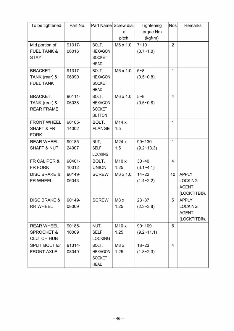
Mid portion of FUEL TANK & STAY
91317-06016
BOLT, HEXAGON SOCKET HEAD
M6 x 1.0 7~10 (0.7~1.0)
2
BRACKET, TANK (rear) & FUEL TANK
91317-06090
BOLT, HEXAGON SOCKET HEAD
M6 x 1.0 5~8 (0.5~0.8)
1
BRACKET, TANK (rear) & REAR FRAME
90111-06038
BOLT, HEXAGON SOCKET BUTTON
M6 x 1.0 5~8 (0.5~0.8)
4
FRONT WHEEL SHAFT & FR FORK
90105-14002
BOLT, FLANGE
M14 x 1.5
1
REAR WHEEL SHAFT & NUT
90185-24007
NUT, SELF LOCKING
M24 x 1.5
90~130 (9.2~13.3)
1
FR CALIPER & FR FORK
90401-10012
BOLT, UNION
M10 x 1.25
30~40 (3.1~4.1)
4
DISC BRAKE & FR WHEEL
90149-06043
SCREW M6 x 1.0 14~22 (1.4~2.2)
10 APPLY LOCKING AGENT (LOCKTITE®).
DISC BRAKE & RR WHEEL
90149-08009
SCREW M8 x 1.25
23~37 (2.3~3.8)
5 APPLY LOCKING AGENT (LOCKTITE®).
REAR WHEEL SPROCKET & CLUTCH HUB
90185-10009
NUT, SELF LOCKING
M10 x 1.25
90~109 (9.2~11.1)
6
SPLIT BOLT for FRONT AXLE
91314-08040
BOLT, HEXAGON SOCKET HEAD
M8 x 1.25
18~23 (1.8~2.3)
4
To be tightened Part No. Part Name Screw dia.x
pitch
Tightening torque Nm
(kgf•m)
Nos Remarks
– 46 –

Tightening the Cylinder Head (Turn-of-Nut Method)1. Tighten the bolts in the tightening sequence of 1 to 7 to a snug torque of 28N•m (2.8kgf•m).2. Tighten the bolts in the tightening sequence of 8 and 9 to a snug torque of 36N•m
(3.6kgf•m).3. Tighten the bolt in the tightening sequence of 10 to a snug torque of 28N•m (2.8kgf•m).4. Retighten the bolts in the tightening sequence of 1 to 10 to a turn-of-nut angle of 55°.
NOTE:The numbers 1 to 10 show the sequence in which the bolts are tightened.Apply engine oil to the bolt threads, contact surfaces, and washers.
These numbers indicate the tightening sequence.
– 47 –

Installing the CrankcaseTightening the bolts1. Tighten the bolts in the tightening sequence of 1 to 10 to 20Nm (2.0kg•m).2. After loosening the bolts once in the tightening sequence of 1 to 10, retighten them one by
one to 12Nm (1.2kg•m).3. Retighten the bolts in the tightening sequence of 1 to 7 to a turn-of-nut angle of 50°±5°.4. Retighten the bolts in the tightening sequence of 8 and 9 to a turn-of-nut angle of 75°±5°. 5. Retighten the bolt in the sequence of 10 to a turn-of-nut angle of 50°±5°.6. Tighten the bolts in the tightening sequence of 11 and 12 to 24±2Nm (2.4±0.2kgf•m).7. Tighten the bolts in the tightening sequence of 13 to 29 to 10±2Nm (1.0±0.2kgf•m).
NOTE:The numbers 1 to 29 show the sequence in which the bolts are tightened.Apply engine oil to the bolt threads and both sides of the washers.
These numbers indicate the tightening sequence.
– 48 –

– 49 –
YZF-R6 Wire Connecting Diagram

Published by YAMAHA MOTOR ENGINEERING co., LTD


