A-Z OWNER'S MANUAL. Contents - MINIUSA · MINI Motorer’s Guide app The Owner's Manual is...
278
OWNER'S MANUAL. MINI COUNTRYMAN. Contents A-Z Online Edition for Part no. 01 40 2 976 632 - X/16
Transcript of A-Z OWNER'S MANUAL. Contents - MINIUSA · MINI Motorer’s Guide app The Owner's Manual is...
OWNER'S MANUAL.MINI COUNTRYMAN.
ContentsA-Z
Online Edition for Part no. 01 40 2 976 632 - X/16


MINI Owner's Manual for the vehicleThank you for choosing a MINI.The more familiar you are with your vehicle, the better controlyou will have on the road. We therefore strongly suggest:Read this Owner's Manual before starting off in your new MINI.Also use the Integrated Owner's Manual in your vehicle. It con‐tains important information on vehicle operation that will helpyou make full use of the technical features available in yourMINI. The manual also contains information designed to en‐hance operating reliability and road safety, and to contribute tomaintaining the value of your MINI.Any updates made after the editorial deadline can be found inthe appendix of the printed Owner's Manual for the vehicle.Get started now. We wish you driving fun and inspiration withyour MINI.
Online Edition for Part no. 01 40 2 976 632 - X/16

© 2016 Bayerische Motoren WerkeAktiengesellschaftMunich, GermanyReprinting, including excerpts, only with the writtenconsent of BMW AG, Munich.US English ID5 X/16, 11 16 490Printed on environmentally friendly paper, bleachedwithout chlorine, suitable for recycling.
Online Edition for Part no. 01 40 2 976 632 - X/16
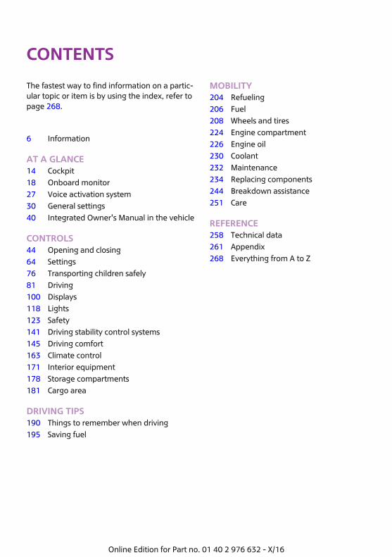
ContentsThe fastest way to find information on a partic‐ular topic or item is by using the index, refer topage 268.
6 Information
AT A GLANCE14 Cockpit18 Onboard monitor27 Voice activation system30 General settings40 Integrated Owner's Manual in the vehicle
CONTROLS44 Opening and closing64 Settings76 Transporting children safely81 Driving100 Displays118 Lights123 Safety141 Driving stability control systems145 Driving comfort163 Climate control171 Interior equipment178 Storage compartments181 Cargo area
DRIVING TIPS190 Things to remember when driving195 Saving fuel
MOBILITY204 Refueling206 Fuel208 Wheels and tires224 Engine compartment226 Engine oil230 Coolant232 Maintenance234 Replacing components244 Breakdown assistance251 Care
REFERENCE258 Technical data261 Appendix268 Everything from A to Z
Online Edition for Part no. 01 40 2 976 632 - X/16
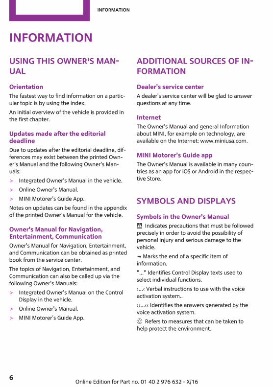
InformationUsing this Owner's Man‐ualOrientationThe fastest way to find information on a partic‐ular topic is by using the index.An initial overview of the vehicle is provided inthe first chapter.
Updates made after the editorialdeadlineDue to updates after the editorial deadline, dif‐ferences may exist between the printed Own‐er's Manual and the following Owner's Man‐uals:▷ Integrated Owner's Manual in the vehicle.▷ Online Owner's Manual.▷ MINI Motorer’s Guide App.Notes on updates can be found in the appendixof the printed Owner's Manual for the vehicle.
Owner's Manual for Navigation,Entertainment, CommunicationOwner's Manual for Navigation, Entertainment,and Communication can be obtained as printedbook from the service center.The topics of Navigation, Entertainment, andCommunication can also be called up via thefollowing Owner's Manuals:▷ Integrated Owner's Manual on the Control
Display in the vehicle.▷ Online Owner's Manual.▷ MINI Motorer’s Guide App.
Additional sources of in‐formationDealer’s service centerA dealer’s service center will be glad to answerquestions at any time.
InternetThe Owner's Manual and general Informationabout MINI, for example on technology, areavailable on the Internet: www.miniusa.com.
MINI Motorer’s Guide appThe Owner's Manual is available in many coun‐tries as an app for iOS or Android in the respec‐tive Store.
Symbols and displaysSymbols in the Owner's Manual
Indicates precautions that must be followedprecisely in order to avoid the possibility ofpersonal injury and serious damage to thevehicle.◄ Marks the end of a specific item ofinformation."..." Identifies Control Display texts used toselect individual functions.›...‹ Verbal instructions to use with the voiceactivation system..››...‹‹ Identifies the answers generated by thevoice activation system.
Refers to measures that can be taken tohelp protect the environment.
Seite 6
Information
6 Online Edition for Part no. 01 40 2 976 632 - X/16

Action stepsAction steps to be carried out are presented asnumbered list. The steps must be carried out inthe defined order.
1. First action step.2. Second action step.
EnumerationsEnumerations without mandatory order or al‐ternative possibilities are presented as list withbullet points.▷ First possibility.▷ Second possibility.
Symbols on vehicle components Indicates that you should consult the
relevant section of this Owner's Manual forinformation on a particular part or assembly.
Vehicle features and op‐tionsThis Owner's Manual describes all models andall standard, country-specific and optionalequipment that is offered in the model series.Therefore, this Owner's Manual also describesand illustrates features and functions that arenot available in your vehicle, for example be‐cause of the selected optional features or thecountry-specific version.This also applies to safety-related functions andsystems.When using these functions and systems, theapplicable laws and regulations must be ob‐served.For any options and equipment not describedin this Owner's Manual, refer to the Supple‐mentary Owner's Manuals.Your BMW dealer’s service center is happy toanswer any questions that you may have aboutthe features and options applicable to your ve‐hicle.
Status of the Owner'sManualBasic informationThe manufacturer of your vehicle pursues apolicy of constant development that is con‐ceived to ensure that our vehicles continue toembody the highest quality and safety stand‐ards. In rare cases, therefore, the features de‐scribed in this Owner's Manual may differ fromthose in your vehicle.
Updates made after the editorialdeadlineDue to updates after the editorial deadline, dif‐ferences may exist between the printed Own‐er's Manual and the following Owner's Man‐uals:▷ Integrated Owner's Manual in the vehicle.▷ Online Owner's Manual.▷ MINI Motorer’s Guide App.Notes on updates can be found in the appendixof the printed Owner's Manual for the vehicle.
For Your Own SafetyManufacturerThe manufacturer of this MINI is BayerischeMotoren Werke Aktionengesellschaft, BMW AG.
Intended useObserve the following when using the vehicle:▷ Owner's Manual.▷ Information on the vehicle. Do not remove
stickers.▷ Technical vehicle data.▷ The traffic, speed, and safety laws where
the vehicle is driven.▷ Vehicle documents and statutory docu‐
ments.
Seite 7
Information
7Online Edition for Part no. 01 40 2 976 632 - X/16
WarrantyYour vehicle is technically configured for theoperating conditions and registration require‐ments applying in the country of first deliveryalso known as homologation. If your vehicle isto be operated in a different country it mightbe necessary to adapt your vehicle to poten‐tially differing operating conditions and permitrequirements. If your vehicle does not complywith the homologation requirements in a cer‐tain country you may not be able to lodge war‐ranty claims for your vehicle there. Further in‐formation on warranty is available from adealer’s service center.
Maintenance and repairsAdvanced technology, e. g. the use of modernmaterials and high-performance electronics,requires suitable maintenance and repair work.The manufacturer of your vehicle recommendsthat you entrust corresponding procedures to aMINI dealer’s service center. If you choose touse another service facility, the manufacturer ofyour vehicle recommends use of a facility thatperforms work, for instance maintenance andrepair, according to MINI specifications withproperly trained personnel, referred to in thisOwner's Manual as "another qualified servicecenter or repair shop".If work is performed improperly, for instancemaintenance and repair, there is a risk of sub‐sequent damage and related safety risks.
Parts and accessoriesThe manufacturer of your vehicle recommendsthe use of parts and accessory products ap‐proved by the manufacturer of the MINI.Approved parts and accessories, and advice ontheir use and installation are available from aMINI dealer's service center.MINI parts and accessories were tested by themanufacturer of the MINI for their safety andsuitability in MINI vehicles.
The manufacturer of your vehicle warrants gen‐uine MINI parts and accessories.The manufacturer of your vehicle does notevaluate whether each individual product fromanother manufacturer can be used with MINIvehicles without presenting a safety hazard,even if a country-specific official approval wasissued. The manufacturer of your vehicle doesnot evaluate whether these products are suita‐ble for MINI vehicles under all usage conditions.
California Proposition 65 WarningCalifornia laws require us to state the followingwarning:Engine exhaust and a wide variety of automo‐bile components and parts, including compo‐nents found in the interior furnishings in a vehi‐cle, contain or emit chemicals known to theState of California to cause cancer and birth de‐fects and reproductive harm. In addition, cer‐tain fluids contained in vehicles and certainproducts of component wear contain or emitchemicals known to the State of California tocause cancer and birth defects or other repro‐ductive harm. Battery posts, terminals and re‐lated accessories contain lead and lead com‐pounds. Wash your hands after handling. Usedengine oil contains chemicals that have causedcancer in laboratory animals. Always protectyour skin by washing thoroughly with soap andwater.
Service and warrantyWe recommend that you read this publicationthoroughly. Your vehicle is covered by the fol‐lowing warranties:▷ New Vehicle Limited Warranty.▷ Rust Perforation Limited Warranty.▷ Federal Emissions System Defect Warranty.▷ Federal Emissions Performance Warranty.▷ California Emission Control System Limited
Warranty.
Seite 8
Information
8 Online Edition for Part no. 01 40 2 976 632 - X/16

Detailed information about these warranties islisted in the Service and Warranty InformationBooklet for US models or in the Warranty andService Guide Booklet for Canadian models.Your vehicle has been specifically adapted anddesigned to meet the particular operating con‐ditions and homologation requirements in yourcountry and continental region in order to de‐liver the full driving pleasure while the vehicle isoperated under those conditions. If you wish tooperate your vehicle in another country or re‐gion, you may be required to adapt your vehi‐cle to meet different prevailing operating con‐ditions and homologation requirements. Youshould also be aware of any applicable war‐ranty limitations or exclusions for such countryor region. In such case, please contact Cus‐tomer Relations for further information.
MaintenanceMaintain the vehicle regularly to sustain theroad safety, operational reliability and the NewVehicle Limited Warranty.Specifications for required maintenance meas‐ures:▷ MINI Maintenance system▷ Service and Warranty Information Booklet
for US models▷ Warranty and Service Guide Booklet for
Canadian modelsIf the vehicle is not maintained according tothese specifications, this could result in seriousdamage to the vehicle. Such damage is notcovered by the MINI New Vehicle Limited War‐ranty.
Data memoryMany electronic components on your vehicleare equipped with data memories that tempo‐rarily or permanently store technical informa‐tion about the condition of the vehicle, eventsand faults. This technical information generally
records the state of a component, a module, asystem or the environment:▷ Operating mode of system components,
e.g., fill levels.▷ Status messages for the vehicle and from its
individual components, for example wheelrotational speed, wheel speed, decelera‐tion, transverse acceleration.
▷ Malfunctions and faults in important systemcomponents, e.g., lights and brakes.
▷ Responses by the vehicle to special situa‐tions such as airbag deployment or engag‐ing the stability control system.
▷ Ambient conditions, such as temperature.This data is purely technical in nature and isused to detect and correct faults and to opti‐mize vehicle functions. Motion profiles overroutes traveled cannot be created from thisdata. When service offerings are used, for ex‐ample repair services, service processes, war‐ranty claims, quality assurance, this technicalinformation can be read out from the eventand fault memories by employees of a dealer’sservice center or another qualified service cen‐ter or repair shop, including the manufacturer,using special diagnostic tools. You can obtainfurther information there if you need it. Afteran error is corrected, the information in thefault memory is deleted or overwritten on acontinuous basis.With the vehicle in use there are situationswhere you can associate this technical datawith individuals if combined with other infor‐mation, e.g., an accident report, damage to thevehicle, eye witness accounts — possibly withthe assistance of an expert.Additional functions that are contractuallyagreed with the customer - such as vehicleemergency locating - allow certain vehicle datato be transmitted from the vehicle.
Seite 9
Information
9Online Edition for Part no. 01 40 2 976 632 - X/16
Event Data Recorder EDRThis vehicle is equipped with an event data re‐corder EDR. The main purpose of an EDR is torecord, in certain crash or near crash-like situa‐tions, such as an air bag deployment or hittinga road obstacle, data that will assist in under‐standing how a vehicle’s systems performed.The EDR is designed to record data related tovehicle dynamics and safety systems for a shortperiod of time, typically 30 seconds or less.The EDR in this vehicle is designed to recordsuch data as:▷ How various systems in your vehicle were
operating.▷ Whether or not the driver and passenger
safety belts were fastened.▷ How far, if at all, the driver was depressing
the accelerator and/or brake pedal.▷ How fast the vehicle was traveling.These data can help provide a better under‐standing of the circumstances in which crashesand injuries occur.EDR data are recorded by your vehicle only if anontrivial crash situation occurs; no data are re‐corded by the EDR under normal driving condi‐tions and no personal data, e. g., name, gen‐der, age, and crash location, are recorded.However, other parties, such as law enforce‐ment, could combine the EDR data with thetype of personally identifying data routinely ac‐quired during a crash investigation.To read data recorded by an EDR, specialequipment is required, and access to the vehi‐cle or the EDR is needed. In addition to the ve‐hicle manufacturer, other parties, such as lawenforcement, that have the special equipment,can read the information if they have access tothe vehicle or the EDR.
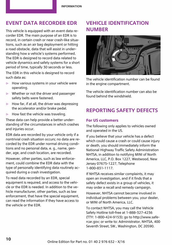
Vehicle identificationnumber
The vehicle identification number can be foundin the engine compartment.
The vehicle identification number can also befound behind the windshield.
Reporting safety defectsFor US customersThe following only applies to vehicles ownedand operated in the US.If you believe that your vehicle has a defectwhich could cause a crash or could cause injuryor death, you should immediately inform theNational Highway Traffic Safety AdministrationNHTSA, in addition to notifying MINI of NorthAmerica, LLC, P.O. Box 1227, Westwood, NewJersey 07675-1227, Telephone1-800-831-1117.If NHTSA receives similar complaints, it mayopen an investigation, and if it finds that asafety defect exists in a group of vehicles, itmay order a recall and remedy campaign.However, NHTSA cannot become involved inindividual problems between you, your dealer,or MINI of North America, LLC.To contact NHTSA, you may call the VehicleSafety Hotline toll-free at 1-888-327-4236(TTY: 1-800-424-9153); go to http://www.safe‐rcar.gov; or write to: Administrator, NHTSA, 400Seventh Street, SW., Washington, DC 20590.
Seite 10
Information
10 Online Edition for Part no. 01 40 2 976 632 - X/16
You can also obtain other information aboutmotor vehicle safety from http://www.safe‐rcar.gov
For Canadian customersCanadian customers who wish to report asafety-related defect to Transport Canada, De‐fect Investigations and Recalls, may telephonethe toll-free hotline 1-800-333-0510. You canalso obtain other information about motor ve‐hicle safety from http://www.tc.gc.ca/roadsaf‐ety.
Seite 11
Information
11Online Edition for Part no. 01 40 2 976 632 - X/16

WATCH ME.
Online Edition for Part no. 01 40 2 976 632 - X/16
AT A GLANCE
CONTROLS
DRIVING TIPS
MOBILITY
REFERENCE
Online Edition for Part no. 01 40 2 976 632 - X/16
CockpitVehicle features and op‐tionsThis chapter describes all standard, country-specific and optional features offered with theseries. It also describes features that are not
necessarily available in your vehicle, e. g., dueto the selected options or country versions. Thisalso applies to safety-related functions and sys‐tems. When using these functions and systems,the applicable laws and regulations must beobserved.
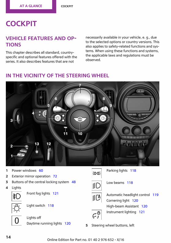
In the vicinity of the steering wheel
1 Power windows 602 Exterior mirror operation 723 Buttons of the central locking system 484 Lights
Front fog lights 121
Light switch 118
Lights offDaytime running lights 120
Parking lights 118
Low beams 118
Automatic headlight control 119Cornering light 120High-beam Assistant 120Instrument lighting 121
5 Steering wheel buttons, left
Seite 14
AT A GLANCE Cockpit
14 Online Edition for Part no. 01 40 2 976 632 - X/16
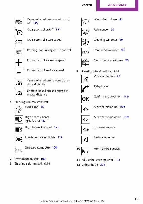
Camera-based cruise control on/off 145
Cruise control on/off 151
Cruise control: store speed
Pausing, continuing cruise control
Cruise control: increase speed
Cruise control: reduce speed
Camera-based cruise control: re‐duce distance
Camera-based cruise control: in‐crease distance
6 Steering column stalk, leftTurn signal 87
High beams, head‐light flasher 87
High-beam Assistant 120
Roadside parking lights 119
Onboard computer 109
7 Instrument cluster 1008 Steering column stalk, right
Windshield wipers 91
Rain sensor 92
Cleaning windows 89
Rear window wiper 90
Clean the rear window 90
9 Steering wheel buttons, rightVoice activation 27
Telephone
Confirm the selection 109
Move selection up 109
Move selection down 109
Increase volume
Reduce volume
10 Horn, entire surface
11 Adjust the steering wheel 7412 Unlock hood 224
Seite 15
Cockpit AT A GLANCE
15Online Edition for Part no. 01 40 2 976 632 - X/16
13 Operate the tailgate 52
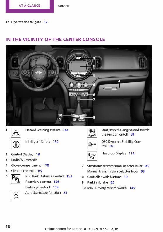
In the vicinity of the center console
1 Hazard warning system 244
Intelligent Safety 132
2 Control Display 183 Radio/Multimedia4 Glove compartment 1785 Climate control 1636 PDC Park Distance Control 153
Rearview camera 156Parking assistant 159Auto Start/Stop function 83
Start/stop the engine and switchthe ignition on/off 81
DSC Dynamic Stability Con‐trol 141
Head-up Display 114
7 Steptronic transmission selector lever 95Manual transmission selector lever 95
8 Controller with buttons 199 Parking brake 8510 MINI Driving Modes switch 143
Seite 16
AT A GLANCE Cockpit
16 Online Edition for Part no. 01 40 2 976 632 - X/16
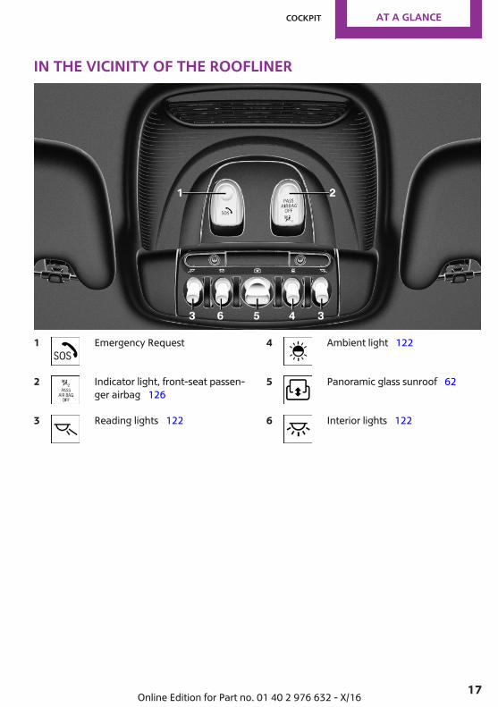
In the vicinity of the roofliner
1 Emergency Request
2 Indicator light, front-seat passen‐ger airbag 126
3 Reading lights 122
4 Ambient light 122
5 Panoramic glass sunroof 62
6 Interior lights 122
Seite 17
Cockpit AT A GLANCE
17Online Edition for Part no. 01 40 2 976 632 - X/16
Onboard monitorVehicle features and op‐tionsThis chapter describes all standard, country-specific and optional features offered with theseries. It also describes features that are notnecessarily available in your vehicle, e. g., dueto the selected options or country versions. Thisalso applies to safety-related functions and sys‐tems. When using these functions and systems,the applicable laws and regulations must beobserved.
ConceptThe onboard monitor combines the functionsof a multitude of switches. Thus, these func‐tions can be operated from a central location.
Safety informationWARNINGOperating the integrated information sys‐
tems and communication devices while drivingcan distract from traffic. It is possible to losecontrol of the vehicle. There is a risk of an acci‐dent. Only use the systems or devices when thetraffic situation allows. If necessary, stop anduse the systems and devices while the vehicle isstationary.◀
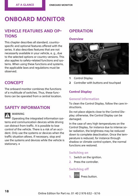
OperationOverview
1 Control Display2 Controller with buttons and touchpad
Control Display
General informationTo clean the Control Display, follow the care in‐structions.Do not place objects close to the Control Dis‐play; otherwise, the Control Display can bedamaged.In the case of very high temperatures on theControl Display, for instance due to intense so‐lar radiation, the brightness may be reduceddown to complete deactivation. Once the tem‐perature is reduced, for instance throughshadow or climate control system, the normalfunctions are restored.
Switching on1. Switch on the ignition.2. Press the controller.
Switching off
1. Press button.
Seite 18
AT A GLANCE Onboard monitor
18 Online Edition for Part no. 01 40 2 976 632 - X/16
2. "Turn off control display"
Controller
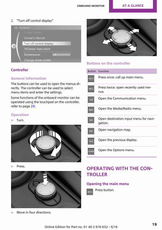
General informationThe buttons can be used to open the menus di‐rectly. The controller can be used to selectmenu items and enter the settings.Some functions of the onboard monitor can beoperated using the touchpad on the controller,refer to page 23:
Operation▷ Turn.
▷ Press.
▷ Move in four directions.
Buttons on the controller
Button Function
Press once: call up main menu.
Press twice: open recently used me‐nus.
Open the Communication menu.
Open the Media/Radio menu.
Open destination input menu for navi‐gation.
Open navigation map.
Open the previous display.
Open the Options menu.
Operating with the con‐trollerOpening the main menu
Press button.
Seite 19
Onboard monitor AT A GLANCE
19Online Edition for Part no. 01 40 2 976 632 - X/16

The main menu is displayed.All onboard monitor functions can be called upvia the main menu.
Selecting menu itemsHighlighted menu items can be selected.
1. Turn the controller until the desired menuitem is highlighted.
2. Press the controller.
Menu items in the Owner's ManualIn the Owner's Manual, menu items that can beselected are set in quotation marks, for in‐stance "System settings".
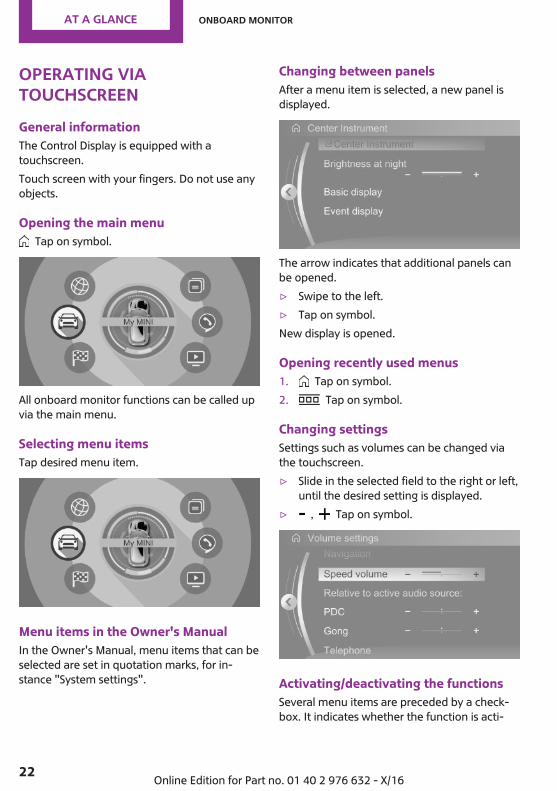
Changing between panelsAfter a menu item is selected, for instance"System settings", a new panel is displayed.▷ Move the controller to the left.
Closes current panel and shows previousdisplay.
▷ Press button.The previous display opens.
▷ Move the controller to the right.New display is opened.
The arrow indicates that additional panels canbe opened.
Opening recently used menusThe recently used menus can be displayed.
Press button twice.
Opening the Options menuPress button.
The "Options" menu is displayed.
The Options menu consists of various areas:▷ Screen settings, for instance "Split screen".▷ Control options for the selected main
menu, for instance for "Media/Radio".▷ If applicable, further operating options for
the selected menu, for instance "Savestation".
Changing settings1. Select a field.
Seite 20
AT A GLANCE Onboard monitor
20 Online Edition for Part no. 01 40 2 976 632 - X/16

2. Turn the controller until the desired settingis displayed.
3. Press the controller.
Activating/deactivating the functionsSeveral menu items are preceded by a check‐box. It indicates whether the function is acti‐vated or deactivated. Selecting the menu itemactivates or deactivates the function.
Function is activated. Function is deactivated.
Entering letters and numbers
General informationLetters and numbers can be entered via thecontroller.The keyboard's display changes automatically.
Input1. Turn the controller: select letters or num‐
bers.2. : confirm entry.
Symbol Function
Press the controller: delete let‐ters or number.
or
Hold the controller down: deleteall letters or numbers.
Switching between upper/lower case,numbers and charactersDepending on the menu, you can switch be‐tween entering upper and lower case lettersand numbers:Symbol Function
Enter the letters.
Enter the numbers.
or
Change between capital andlower-case letters.
Without navigation system Select the symbol.
Entry comparisonWhen entering names and addresses, thechoice is narrowed down with every letter en‐tered and letters may be added automatically.Entries are continuously compared with datastored in the vehicle.▷ Only those letters are offered during entry
for which data is available.▷ Destination search: place names can be en‐
tered in all languages that are available onthe Control Display.
Using alphabetical listsFor alphabetical lists with more than 30 entries,the letters for which there is an entry are dis‐played at the left edge.
1. Turn the controller to the left or rightquickly.All letters for which there are entries aredisplayed on the left edge.
2. Select the first letter of the desired entry.The first entry of the selected letter is dis‐played.
Seite 21
Onboard monitor AT A GLANCE
21Online Edition for Part no. 01 40 2 976 632 - X/16
Operating viatouchscreenGeneral informationThe Control Display is equipped with atouchscreen.Touch screen with your fingers. Do not use anyobjects.
Opening the main menu Tap on symbol.
All onboard monitor functions can be called upvia the main menu.
Selecting menu itemsTap desired menu item.
Menu items in the Owner's ManualIn the Owner's Manual, menu items that can beselected are set in quotation marks, for in‐stance "System settings".
Changing between panelsAfter a menu item is selected, a new panel isdisplayed.
The arrow indicates that additional panels canbe opened.▷ Swipe to the left.▷ Tap on symbol.New display is opened.
Opening recently used menus1. Tap on symbol.2. Tap on symbol.
Changing settingsSettings such as volumes can be changed viathe touchscreen.▷ Slide in the selected field to the right or left,
until the desired setting is displayed.▷ , Tap on symbol.
Activating/deactivating the functionsSeveral menu items are preceded by a check‐box. It indicates whether the function is acti‐
Seite 22
AT A GLANCE Onboard monitor
22 Online Edition for Part no. 01 40 2 976 632 - X/16

vated or deactivated. Selecting the menu itemactivates or deactivates the function.
Function is activated. Function is deactivated.
Entering letters and numbers
General informationLetters and numbers can be entered using thecontroller or the touchscreen.The keyboard's display changes automatically.Symbol Function
Tapping the symbol: delete the letteror number.
Tapping and holding the symbol foran extended period: delete all lettersor numbers.
Switching between upper/lower case,numbers and characters
Symbol Function
Enter the letters.
Enter the numbers.
or
Change between capital andlower-case letters.
Operating navigation mapThe navigation map can be moved with thetouchscreen.Function Operation
Enlarge/shrinkmap.
Drag in or out with the fin‐gers.
Rotate map. Move two fingers in a circle.
TouchpadGeneral informationSome functions of the onboard monitor can beoperated using the touchpad on the controller:
Selecting functions1. "My MINI"2. "System settings"3. "Touchpad"4. Select the desired function.
▷ "Speller": enter letters and numbers.▷ "Map": using the map.▷ "Search fields": write letters without se‐
lecting the list field.▷ "Audio feedback": pronounces entered
letters and numbers.
Entering letters and numbersEntering letters requires some practice at thebeginning. When entering, pay attention to thefollowing:▷ The system distinguishes between upper
and lower-case letters and numbers. Tomake entries, it may be necessary tochange between upper and lower-case let‐ters, numbers and characters, refer topage 21.
▷ Enter characters as they are displayed onthe Control Display.
▷ Always enter associated characters, such asaccents or periods so that the letter can beclearly recognized. The set language deter‐mines what input is possible. Where neces‐sary, enter special characters via the con‐troller.
▷ To delete a character, swipe to the left onthe touchpad.
▷ To enter a blank space, swipe to the right inthe center of the touchpad.
Seite 23
Onboard monitor AT A GLANCE
23Online Edition for Part no. 01 40 2 976 632 - X/16
▷ To enter a hyphen, swipe to the right in theupper area of the touchpad.
▷ To enter an underscore, swipe to the rightin the lower area of the touchpad.
Using the mapThe map in the navigation system can bemoved via the touchpad.Function Operation
Move map. Swipe in the appropriate di‐rection.
Enlarge/shrinkmap.
Drag in or out on the touch‐pad with fingers.
Display menu. Tap once.
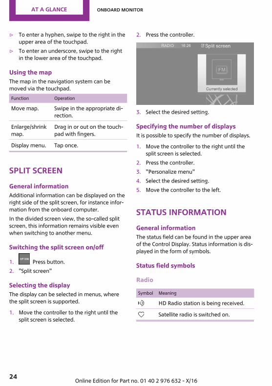
Split screenGeneral informationAdditional information can be displayed on theright side of the split screen, for instance infor‐mation from the onboard computer.In the divided screen view, the so-called splitscreen, this information remains visible evenwhen switching to another menu.
Switching the split screen on/off
1. Press button.2. "Split screen"
Selecting the displayThe display can be selected in menus, wherethe split screen is supported.
1. Move the controller to the right until thesplit screen is selected.
2. Press the controller.
3. Select the desired setting.
Specifying the number of displaysIt is possible to specify the number of displays.
1. Move the controller to the right until thesplit screen is selected.
2. Press the controller.3. "Personalize menu"4. Select the desired setting.5. Move the controller to the left.
Status informationGeneral informationThe status field can be found in the upper areaof the Control Display. Status information is dis‐played in the form of symbols.
Status field symbols
Radio
Symbol Meaning
HD Radio station is being received.
Satellite radio is switched on.
Seite 24
AT A GLANCE Onboard monitor
24 Online Edition for Part no. 01 40 2 976 632 - X/16
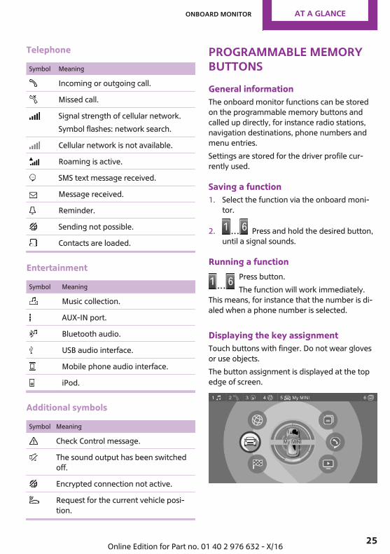
Telephone
Symbol Meaning
Incoming or outgoing call.
Missed call.
Signal strength of cellular network.Symbol flashes: network search.
Cellular network is not available.
Roaming is active.
SMS text message received.
Message received.
Reminder.
Sending not possible.
Contacts are loaded.
Entertainment
Symbol Meaning
Music collection.
AUX-IN port.
Bluetooth audio.
USB audio interface.
Mobile phone audio interface.
iPod.
Additional symbols
Symbol Meaning
Check Control message.
The sound output has been switchedoff.
Encrypted connection not active.
Request for the current vehicle posi‐tion.
Programmable memorybuttonsGeneral informationThe onboard monitor functions can be storedon the programmable memory buttons andcalled up directly, for instance radio stations,navigation destinations, phone numbers andmenu entries.Settings are stored for the driver profile cur‐rently used.
Saving a function1. Select the function via the onboard moni‐
tor.
2. Press and hold the desired button,until a signal sounds.
Running a functionPress button.The function will work immediately.
This means, for instance that the number is di‐aled when a phone number is selected.
Displaying the key assignmentTouch buttons with finger. Do not wear glovesor use objects.The button assignment is displayed at the topedge of screen.
Seite 25
Onboard monitor AT A GLANCE
25Online Edition for Part no. 01 40 2 976 632 - X/16
Deleting the button assignments1. Press buttons 1 and 6 simultaneously for
approx. 5 seconds.2. "OK"
Seite 26
AT A GLANCE Onboard monitor
26 Online Edition for Part no. 01 40 2 976 632 - X/16
Voice activation systemVehicle features and op‐tionsThis chapter describes all standard, country-specific and optional features offered with theseries. It also describes features that are notnecessarily available in your vehicle, e. g., dueto the selected options or country versions. Thisalso applies to safety-related functions and sys‐tems. When using these functions and systems,the applicable laws and regulations must beobserved.
The concept▷ Most functions displayed on the Control
Display can be operated by voice com‐mands via the voice activation system. Thesystem supports you with announcementsduring input.
▷ Functions that can only be used when thevehicle is stationary cannot be used via thevoice activation system.
▷ The system uses a special microphone onthe driver's side.
▷ ›...‹ Verbal instructions in the Owner's Man‐ual to use with the voice activation system.
RequirementsVia the Control Display, set a language that isalso supported by the voice activation systemso that the spoken commands can be identi‐fied.To set the language, refer to page 30.
Using the voice activa‐tion systemActivating the voice activation system
1. Press button on the steering wheel.2. Wait for the signal.3. Say the command.
This symbol in the instrument cluster indi‐cates that the voice activation system is active.If no other commands are available, operatethe function via the onboard monitor.
Terminating the voice activationsystem
Press the button on the steering wheelor ›Cancel‹.
Possible commandsMost menu items on the Control Display can bevoiced as commands.Commands from other menus can also be spo‐ken.You may select list entries such as phone listentries via voice activation. Read these list en‐tries out loud exactly as they are shown in therespective list.
Displaying possible commandsThe following is displayed in the top area of theControl Display:▷ Some possible commands for the current
menu.▷ Some possible commands from other me‐
nus.▷ Status of the voice recognition.
Seite 27
Voice activation system AT A GLANCE
27Online Edition for Part no. 01 40 2 976 632 - X/16

▷ Encrypted connection is not available.
Help on the voice activation system▷ To have information on the operating prin‐
ciple of the voice activation system readout loud: ›General information on voicecontrol‹.
▷ To have help for the current menu read outloud: ›Help‹.
Example: opening thetone settingsThe commands of the menu items are spokenjust as they are selected via the controller.
1. Turn on the Entertainment sound output, ifneeded.
2. Press button on the steering wheel.3. ›Radio‹4. ›Tone‹
SettingsSetting the voice dialogYou can set the system to use standard dialogor a short version.The short version of the voice dialog plays backshort messages in abbreviated form.
1. "My MINI"2. "System settings"3. "Language"4. "Speech mode:"5. Select the desired setting.
Selecting the input languageFor some languages, the input language can beselected.
1. "My MINI"2. "System settings"3. "Language"4. "Voice control:"5. Select the desired setting.
Activating voice recognition via theserverThe voice recognition feature via the serverprovides a dictation function and a naturalmethod of entering destinations while improv‐ing the quality of voice recognition. To use thefunctions, data is transmitted to a service pro‐vider via an encrypted connection and storedlocally there.
1. "My MINI"2. "System settings"3. "Language"4. "Server speech recognition"
Speaking during voice outputIt is possible to answer during inquiries of thevoice activation system. The function can bedeactivated if inquiries are often undesirablyinterrupted, for instance due to backgroundnoise or talking.
1. "My MINI"2. "System settings"3. "Language"4. "Speaking during voice output"
Adjusting the volumeTurn the volume button during the spoken in‐structions until the desired volume is set.▷ The volume remains constant even if the
volume of other audio sources is changed.
Seite 28
AT A GLANCE Voice activation system
28 Online Edition for Part no. 01 40 2 976 632 - X/16

▷ The volume is stored for the profile cur‐rently used.
Information on Emer‐gency RequestsDo not use the voice activation system to ini‐tiate an Emergency Request. In stressful situa‐tions, the voice and vocal pitch can change.This can unnecessarily delay the establishmentof a phone connection.
Environmental condi‐tions▷ Say the commands, numbers, and letters
smoothly and with normal volume, empha‐sis, and speed.
▷ Always say commands in the language ofthe voice activation system.
▷ Keep the doors, windows, and glass sun‐roof closed to prevent noise interference.
▷ Avoid making other noise in the vehiclewhile speaking.
Seite 29
Voice activation system AT A GLANCE
29Online Edition for Part no. 01 40 2 976 632 - X/16
General settingsVehicle features and op‐tionsThis chapter describes all standard, country-specific and optional features offered with theseries. It also describes features that are notnecessarily available in your vehicle, e. g., dueto the selected options or country versions. Thisalso applies to safety-related functions and sys‐tems. When using these functions and systems,the applicable laws and regulations must beobserved.
LanguageSetting the languageVia the onboard monitor:
1. "My MINI"2. "System settings"3. "Language"4. "Language:"5. Select the desired setting.The setting is stored for the driver profile cur‐rently used.
Setting the voice dialogVoice dialog for the voice activation system, re‐fer to page 28.
TimeSetting the time zoneVia the onboard monitor:
1. "My MINI"2. "System settings"3. "Date and time"
4. "Time zone:"5. Select the desired setting.The setting is stored for the driver profile cur‐rently used.
Setting the timeVia the onboard monitor:
1. "My MINI"2. "System settings"3. "Date and time"4. "Time:"5. Turn the controller until the desired hours
are displayed.6. Press the controller.7. Turn the controller until the desired mi‐
nutes are displayed.8. Press the controller.The setting is stored for the driver profile cur‐rently used.
Setting the time formatVia the onboard monitor:
1. "My MINI"2. "System settings"3. "Date and time"4. "Time format:"5. Select the desired setting.The setting is stored for the driver profile cur‐rently used.
Seite 30
AT A GLANCE General settings
30 Online Edition for Part no. 01 40 2 976 632 - X/16
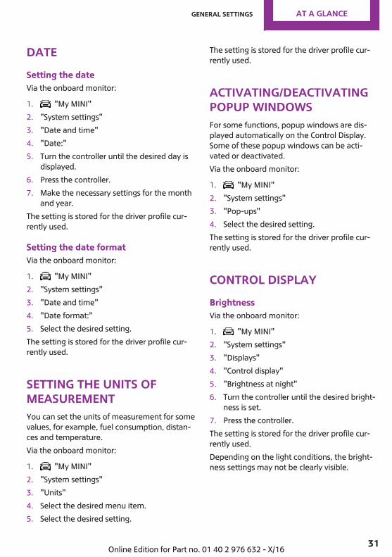
DateSetting the dateVia the onboard monitor:
1. "My MINI"2. "System settings"3. "Date and time"4. "Date:"5. Turn the controller until the desired day is
displayed.6. Press the controller.7. Make the necessary settings for the month
and year.The setting is stored for the driver profile cur‐rently used.
Setting the date formatVia the onboard monitor:
1. "My MINI"2. "System settings"3. "Date and time"4. "Date format:"5. Select the desired setting.The setting is stored for the driver profile cur‐rently used.
Setting the units ofmeasurementYou can set the units of measurement for somevalues, for example, fuel consumption, distan‐ces and temperature.Via the onboard monitor:
1. "My MINI"2. "System settings"3. "Units"4. Select the desired menu item.5. Select the desired setting.
The setting is stored for the driver profile cur‐rently used.
Activating/deactivatingpopup windowsFor some functions, popup windows are dis‐played automatically on the Control Display.Some of these popup windows can be acti‐vated or deactivated.Via the onboard monitor:
1. "My MINI"2. "System settings"3. "Pop-ups"4. Select the desired setting.The setting is stored for the driver profile cur‐rently used.
Control DisplayBrightnessVia the onboard monitor:
1. "My MINI"2. "System settings"3. "Displays"4. "Control display"5. "Brightness at night"6. Turn the controller until the desired bright‐
ness is set.7. Press the controller.The setting is stored for the driver profile cur‐rently used.Depending on the light conditions, the bright‐ness settings may not be clearly visible.
Seite 31
General settings AT A GLANCE
31Online Edition for Part no. 01 40 2 976 632 - X/16
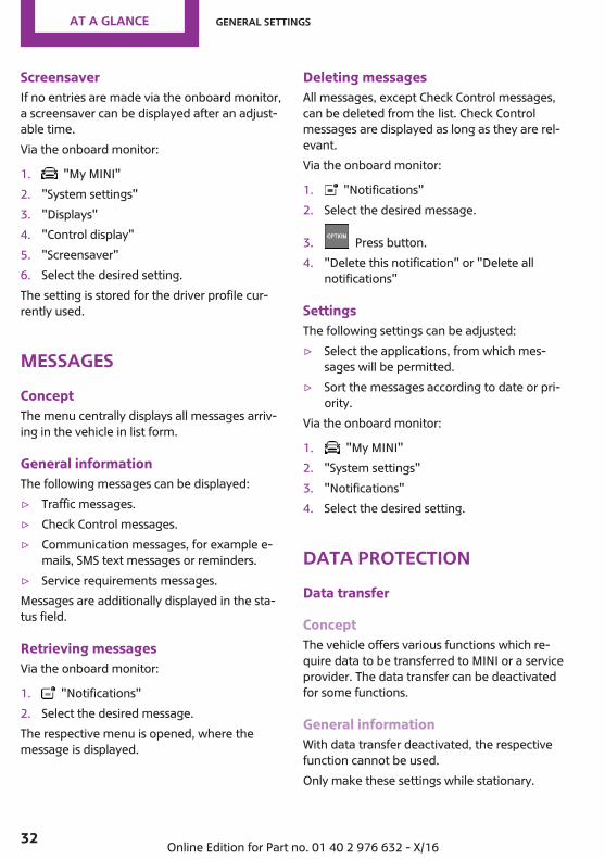
ScreensaverIf no entries are made via the onboard monitor,a screensaver can be displayed after an adjust‐able time.Via the onboard monitor:
1. "My MINI"2. "System settings"3. "Displays"4. "Control display"5. "Screensaver"6. Select the desired setting.The setting is stored for the driver profile cur‐rently used.
MessagesConceptThe menu centrally displays all messages arriv‐ing in the vehicle in list form.
General informationThe following messages can be displayed:▷ Traffic messages.▷ Check Control messages.▷ Communication messages, for example e-
mails, SMS text messages or reminders.▷ Service requirements messages.Messages are additionally displayed in the sta‐tus field.
Retrieving messagesVia the onboard monitor:
1. "Notifications"2. Select the desired message.The respective menu is opened, where themessage is displayed.
Deleting messagesAll messages, except Check Control messages,can be deleted from the list. Check Controlmessages are displayed as long as they are rel‐evant.Via the onboard monitor:
1. "Notifications"2. Select the desired message.
3. Press button.4. "Delete this notification" or "Delete all
notifications"
SettingsThe following settings can be adjusted:▷ Select the applications, from which mes‐
sages will be permitted.▷ Sort the messages according to date or pri‐
ority.Via the onboard monitor:
1. "My MINI"2. "System settings"3. "Notifications"4. Select the desired setting.
Data protectionData transfer
ConceptThe vehicle offers various functions which re‐quire data to be transferred to MINI or a serviceprovider. The data transfer can be deactivatedfor some functions.
General informationWith data transfer deactivated, the respectivefunction cannot be used.Only make these settings while stationary.
Seite 32
AT A GLANCE General settings
32 Online Edition for Part no. 01 40 2 976 632 - X/16
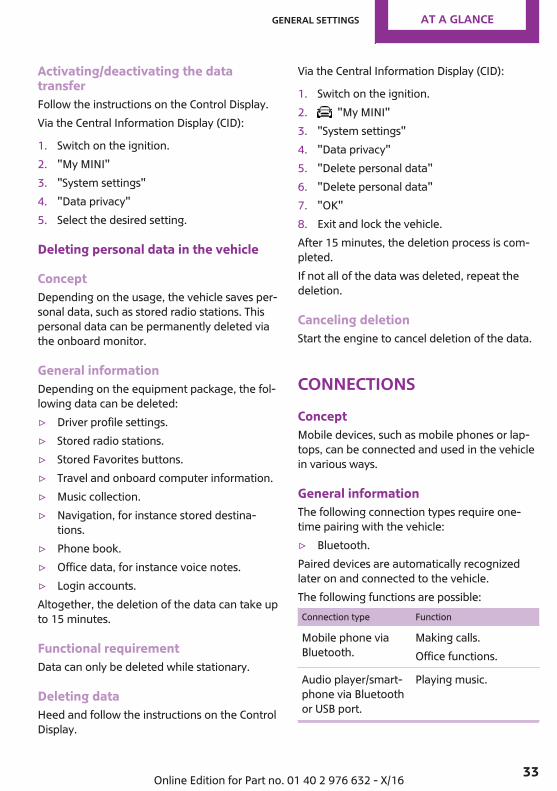
Activating/deactivating the datatransferFollow the instructions on the Control Display.Via the Central Information Display (CID):
1. Switch on the ignition.2. "My MINI"3. "System settings"4. "Data privacy"5. Select the desired setting.
Deleting personal data in the vehicle
ConceptDepending on the usage, the vehicle saves per‐sonal data, such as stored radio stations. Thispersonal data can be permanently deleted viathe onboard monitor.
General informationDepending on the equipment package, the fol‐lowing data can be deleted:▷ Driver profile settings.▷ Stored radio stations.▷ Stored Favorites buttons.▷ Travel and onboard computer information.▷ Music collection.▷ Navigation, for instance stored destina‐
tions.▷ Phone book.▷ Office data, for instance voice notes.▷ Login accounts.Altogether, the deletion of the data can take upto 15 minutes.
Functional requirementData can only be deleted while stationary.
Deleting dataHeed and follow the instructions on the ControlDisplay.
Via the Central Information Display (CID):
1. Switch on the ignition.2. "My MINI"3. "System settings"4. "Data privacy"5. "Delete personal data"6. "Delete personal data"7. "OK"8. Exit and lock the vehicle.After 15 minutes, the deletion process is com‐pleted.If not all of the data was deleted, repeat thedeletion.
Canceling deletionStart the engine to cancel deletion of the data.
ConnectionsConceptMobile devices, such as mobile phones or lap‐tops, can be connected and used in the vehiclein various ways.
General informationThe following connection types require one-time pairing with the vehicle:▷ Bluetooth.Paired devices are automatically recognizedlater on and connected to the vehicle.The following functions are possible:Connection type Function
Mobile phone viaBluetooth.
Making calls.Office functions.
Audio player/smart‐phone via Bluetoothor USB port.
Playing music.
Seite 33
General settings AT A GLANCE
33Online Edition for Part no. 01 40 2 976 632 - X/16
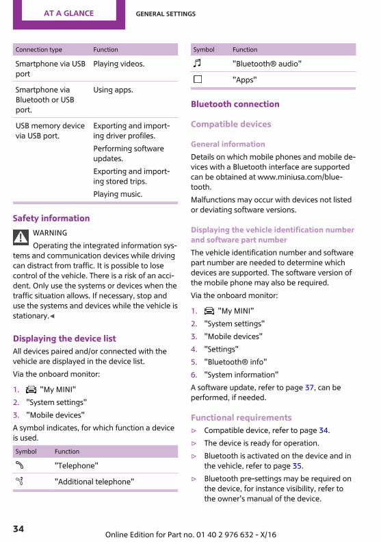
Connection type Function
Smartphone via USBport
Playing videos.
Smartphone viaBluetooth or USBport.
Using apps.
USB memory devicevia USB port.
Exporting and import‐ing driver profiles.Performing softwareupdates.Exporting and import‐ing stored trips.Playing music.
Safety informationWARNINGOperating the integrated information sys‐
tems and communication devices while drivingcan distract from traffic. It is possible to losecontrol of the vehicle. There is a risk of an acci‐dent. Only use the systems or devices when thetraffic situation allows. If necessary, stop anduse the systems and devices while the vehicle isstationary.◀
Displaying the device listAll devices paired and/or connected with thevehicle are displayed in the device list.Via the onboard monitor:
1. "My MINI"2. "System settings"3. "Mobile devices"A symbol indicates, for which function a deviceis used.Symbol Function
"Telephone"
"Additional telephone"
Symbol Function
"Bluetooth® audio"
"Apps"
Bluetooth connection
Compatible devices
General informationDetails on which mobile phones and mobile de‐vices with a Bluetooth interface are supportedcan be obtained at www.miniusa.com/blue‐tooth.Malfunctions may occur with devices not listedor deviating software versions.
Displaying the vehicle identification numberand software part numberThe vehicle identification number and softwarepart number are needed to determine whichdevices are supported. The software version ofthe mobile phone may also be required.Via the onboard monitor:
1. "My MINI"2. "System settings"3. "Mobile devices"4. "Settings"5. "Bluetooth® info"6. "System information"A software update, refer to page 37, can beperformed, if needed.
Functional requirements▷ Compatible device, refer to page 34.▷ The device is ready for operation.▷ Bluetooth is activated on the device and in
the vehicle, refer to page 35.▷ Bluetooth pre-settings may be required on
the device, for instance visibility, refer tothe owner's manual of the device.
Seite 34
AT A GLANCE General settings
34 Online Edition for Part no. 01 40 2 976 632 - X/16
▷ A number with at least four and a maxi‐mum of 16 digits should be defined as theBluetooth passkey. Required for one-timepairing only.
Activating BluetoothVia the onboard monitor:
1. "My MINI"2. "System settings"3. "Mobile devices"4. "Settings"5. "Bluetooth®"
Activating/deactivating telephonefunctionsTo use all supported functions of a mobilephone, the following functions must be acti‐vated prior to pairing.Via the onboard monitor:
1. "My MINI"2. "System settings"3. "Mobile devices"4. "Settings"5. Select desired setting:
▷ "Office"Activate function to transmit short mes‐sages, e-mails, calendars, tasks, notes,and reminders to the vehicle. Costs canbe incurred by transmitting all data tothe vehicle.
▷ "Contact images"Activate function to show the contactpictures.
6. Move the controller to the left.
Pairing the mobile device with thevehicleVia the onboard monitor:
1. "My MINI"2. "System settings"3. "Mobile devices"4. "Connect new device"5. Select the functions for which the device is
to be used:▷ "Telephone"▷ "Bluetooth® audio"▷ "Apps"The Bluetooth name of the vehicle is dis‐played on the Control Display.
6. Search for Bluetooth devices in the vicinityof the mobile device.The Bluetooth name of the vehicle appearson the mobile device display.Select the Bluetooth name of the vehicle.
7. Depending on the mobile device, a controlnumber is displayed or the control numbermust be entered.▷ Compare the control number displayed
on the Control Display with the controlnumber on the display of the device.Confirm the control number on the de‐vice and on the Control Display.
▷ Enter and confirm the same controlnumber on the device and via the on‐board monitor.
The device is connected and displayed inthe device list.
If connection was not successful: FrequentlyAsked Questions, refer to page 38.
USB connection
General informationMobile devices with USB port can be connectedto the USB interface.
Seite 35
General settings AT A GLANCE
35Online Edition for Part no. 01 40 2 976 632 - X/16

▷ Mobile phones supported by the USB inter‐face.
▷ Audio devices with USB port, for instanceMP3 player.
▷ USB storage devices.Common file systems are supported. FAT32and exFAT are the recommended formats.
Information about compatible USB media canbe found at www.miniusa.com/bluetooth.The following applications are possible:▷ Exporting and importing driver profiles, re‐
fer to page 54.▷ Playing music files via USB audio.▷ Playing videos via USB video.▷ Loading of software updates, refer to
page 37.Observe the following when connecting:▷ Do not use force when plugging the con‐
nector into the USB interface.▷ Use a flexible adapter cable.▷ Protect the USB storage device against me‐
chanical damage.▷ Due to the large number of USB media
available on the market, it cannot be guar‐anteed that every device is operable on thevehicle.
▷ Do not expose USB media to extreme envi‐ronmental conditions, such as very hightemperatures; refer to the owner's manualof the device.
▷ Due to the many different compressiontechniques, proper playback of the mediastored on the USB storage device cannot beguaranteed in all cases.
▷ A connected USB storage device will besupplied with charging current via the USBinterface if the device supports this. Athigher temperatures, the USB storage de‐vice may cause a reduction in the chargingcurrent.
▷ To ensure proper transmission of the storeddata, do not charge a USB storage devicevia the onboard socket, when it is con‐nected to the USB interface.
▷ Depending on how the USB storage deviceshould be used, settings may be requiredon the USB storage device, refer to theowner's manual of the device.
Not compatible USB media:▷ USB hard drives.▷ USB hubs.▷ USB memory card readers with multiple in‐
serts.▷ HFS-formatted USB media.▷ Devices such as fans or lights.
Connecting the deviceConnect the USB storage device using a suita‐ble adapter cable to a USB interface, refer topage 176.The USB storage device is connected to the ve‐hicle and displayed in the device list.
Additional functions
Following the initial pairing▷ The device is connected with the vehicle
within a short period of time if the engine isrunning or ignition is switched on.
▷ The data stored on the SIM card or in themobile phone are transferred to the vehicleafter recognition.
▷ For some devices, certain settings may benecessary, for instance authorization, seeowner's manual of the device.
▷ After one-time pairing, the devices are au‐tomatically recognized and reconnectedwhen the ignition is switched on.
Configuring the deviceFunctions can be activated or deactivated forpaired and connected devices.
Seite 36
AT A GLANCE General settings
36 Online Edition for Part no. 01 40 2 976 632 - X/16
Via the onboard monitor:
1. "My MINI"2. "System settings"3. "Mobile devices"4. Select the desired device.5. Select the desired setting.If a function is assigned to a device, the func‐tion will be deactivated where appropriate for adevice that is already connected and the devicewill be disconnected.
Connecting a specific deviceVia the onboard monitor:
1. "My MINI"2. "System settings"3. "Mobile devices"4. Select device.5. "Connect device"The functions that were assigned to the devicebefore disconnecting are assigned to the de‐vice when it is reconnected. If the device is al‐ready connected, these functions are deacti‐vated.
Disconnecting the deviceThe connection of the device to the vehicle isdisconnected.The device remains paired and can be con‐nected again, refer to page 37.Via the onboard monitor:
1. "My MINI"2. "System settings"3. "Mobile devices"4. Select device.5. "Disconnect device"
Deleting the deviceThe device is disconnected and removed fromthe device list.
Via the onboard monitor:
1. "My MINI"2. "System settings"3. "Mobile devices"4. Select device.5. "Delete device"
Swapping the telephone and additionalphoneIf two mobile phones are connected to the ve‐hicle, the functions of the phone and additionalphone can be switched.Via the onboard monitor:
1. "My MINI"2. "System settings"3. "Mobile devices"4. "Settings"5. "Swap telephone/additional tel."
Software update
General informationThe vehicle supports a large number of mobiledevices, for instance mobile phones and MP3players. Software updates are available formany of the supported devices. The vehicle ismaintained up-to-date via regular vehicle soft‐ware updates.Updates and related current information isavailable on the Internet at www.mini.com/update.
Displaying the installed softwareversionThe software version installed in the vehicle isdisplayed.Via the onboard monitor:
1. "My MINI"2. "System settings"
Seite 37
General settings AT A GLANCE
37Online Edition for Part no. 01 40 2 976 632 - X/16
3. "Software update"4. "Show current version"If an update has been carried out before, selectthe desired version to display additional infor‐mation.
Updating software via USBThe software may only be updated when thevehicle is stationary.Via the onboard monitor:
1. Store the file for the software update in themain directory of a USB flash drive.
2. Connect the USB data storage to a USB in‐terface.
3. "My MINI"4. "System settings"5. "Software update"6. "Update software"7. "USB"8. "Install software"9. "OK"10. Wait for the update to complete.11. Confirm system restart.
Restoring the software versionThe software version before the last softwareupdate and the version before the first softwareupdate can be restored.The software may only be restored when thevehicle is stationary.Via the onboard monitor:
1. "My MINI"2. "System settings"3. "Software update"4. "Restore software"5. ▷ "Previous version"
The previous software version is re‐stored.
▷ "Default software settings"
The first software version is restored.6. "Remove software"7. "OK"8. Wait for restore.9. Confirm system restart.
Frequently asked questionsInformation on compatible mobile phones, re‐fer to page 34.All requirements are met and all required stepswere completed in the specified order. Despitethat, the mobile device does not function as ex‐pected.In this case, the following explanations canhelp:Why could the mobile phone not be paired orconnected?▷ There are too many Bluetooth devices con‐
nected to the mobile phone or vehicle.Delete connections with other devices, ifneeded.
▷ Delete all known Bluetooth connectionsfrom the device list on the mobile phoneprior to connecting.Start new device search.
▷ The mobile phone is in power-save modeor has only a limited remaining battery life.Charge the mobile phone in the snap-inadapter, wireless charging tray or via thecharging cable.
▷ Depending on the mobile phone, it is possi‐ble that only one mobile phone can be con‐nected to the vehicle.Unpair the connected mobile phone fromthe vehicle and pair and connect only onemobile phone.
Why does the mobile phone no longer react?▷ The applications on the mobile phone do
not function anymore.Switch the mobile phone off and on again.
Seite 38
AT A GLANCE General settings
38 Online Edition for Part no. 01 40 2 976 632 - X/16
▷ Possibly too high or too low ambient tem‐peratures for mobile phone operation.Do not subject the mobile phone to ex‐treme ambient temperatures.
Why are no telephone functions available?▷ The mobile phone may not be properly
configured, for instance as Bluetooth audiodevice.Connect the mobile phone with the tele‐phone or additional phone function.
Why are no or not all phone book entries dis‐played or why are they incomplete?▷ Transmission of the phone book entries is
not yet complete.▷ It is possible that only the phone book en‐
tries of the mobile phone or the SIM cardare transmitted.
▷ It may not be possible to display phonebook entries with special characters.
▷ It may not be possible to transmit contactsfrom social networks.
▷ The number of phone book entries to bestored is too high.
▷ Data volume of the contact too large, forinstance due to stored information such asnotes.Reduce the data volume of the contact.
▷ A mobile phone can only be connected asaudio source or as telephone.Configure the mobile phone and connect itwith the telephone or additional phonefunction.
Why is the phone connection quality poor?▷ The strength of the Bluetooth signal on the
mobile phone can be adjusted, dependingon the mobile phone.
▷ Insert the mobile phone into the snap-inadapter or place it in the area of the centerconsole.
▷ Insert mobile phone into the wirelesscharging tray.
▷ Adjust the volume of the microphone andloudspeakers separately.
If all points in this list have been checked andthe required function is still not available, con‐tact the hotline, a dealer’s service center or an‐other qualified service center or repair shop.
Seite 39
General settings AT A GLANCE
39Online Edition for Part no. 01 40 2 976 632 - X/16
Integrated Owner's Manual in thevehicleVehicle features and op‐tionsThis chapter describes all standard, country-specific and optional features offered with theseries. It also describes features that are notnecessarily available in your vehicle, e. g., dueto the selected options or country versions. Thisalso applies to safety-related functions and sys‐tems. When using these functions and systems,the applicable laws and regulations must beobserved.
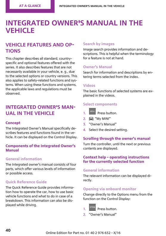
Integrated Owner's Man‐ual in the vehicleConceptThe Integrated Owner's Manual specifically de‐scribes features and functions found in the ve‐hicle. It can be displayed on the Control Display.
Components of the Integrated Owner'sManual
General informationThe Integrated owner's manual consists of fourparts, which offer various levels of informationor possible access.
Quick Reference GuideThe Quick Reference Guide provides informa‐tion how to operate the car, how to use basicvehicle functions and what to do in case of abreakdown. This information can also be dis‐played while driving.
Search by imagesImage search provides information and de‐scriptions. This is helpful when the terminologyfor a feature is not at hand.
Owner's ManualSearch for information and descriptions by en‐tering terms selected from the index.
VideosThe basic functions of selected systems are ex‐plained in the videos.
Select components
1. Press button.2. "My MINI"3. "Owner's Manual"4. Select the desired setting.
Scrolling through the owner's manualTurn the controller, until the next or previouscontents are displayed.
Context help - operating instructionsfor the currently selected function
General informationThe relevant information can be displayed di‐rectly.
Opening via onboard monitorChange directly to the Options menu from thefunction on the Control Display:
1. Press button.2. "Owner's Manual"
Seite 40
AT A GLANCE Integrated Owner's Manual in the vehicle
40 Online Edition for Part no. 01 40 2 976 632 - X/16
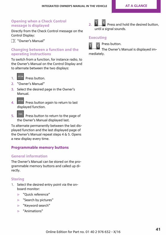
Opening when a Check Controlmessage is displayedDirectly from the Check Control message on theControl Display:
"Owner's Manual"
Changing between a function and theoperating instructionsTo switch from a function, for instance radio, tothe Owner's Manual on the Control Display andto alternate between the two displays:
1. Press button.2. "Owner's Manual"3. Select the desired page in the Owner's
Manual.
4. Press button again to return to lastdisplayed function.
5. Press button to return to the page ofthe Owner's Manual displayed last.
To alternate permanently between the last dis‐played function and the last displayed page ofthe Owner's Manual repeat steps 4 & 5. Opensa new display every time.
Programmable memory buttons
General informationThe Owner's Manual can be stored on the pro‐grammable memory buttons and called up di‐rectly.
Storing1. Select the desired entry point via the on‐
board monitor:▷ "Quick reference"▷ "Search by pictures"▷ "Keyword search"▷ "Animations"
2. Press and hold the desired button,until a signal sounds.
ExecutingPress button.The Owner's Manual is displayed im‐
mediately.
Seite 41
Integrated Owner's Manual in the vehicle AT A GLANCE
41Online Edition for Part no. 01 40 2 976 632 - X/16
HANDLE ME.
Online Edition for Part no. 01 40 2 976 632 - X/16

AT A GLANCE
CONTROLS
DRIVING TIPS
MOBILITY
REFERENCE
Online Edition for Part no. 01 40 2 976 632 - X/16
Opening and closingVehicle features and op‐tionsThis chapter describes all standard, country-specific and optional features offered with theseries. It also describes features that are notnecessarily available in your vehicle, e. g., dueto the selected options or country versions. Thisalso applies to safety-related functions and sys‐tems. When using these functions and systems,the applicable laws and regulations must beobserved.
Remote controlGeneral informationThe vehicle is supplied with two remote con‐trols with integrated key.Each remote control contains a replaceablebattery. Replacing the battery, refer topage 46.You may set the key functions depending onthe optional features and country-specific ver‐sion. Settings, refer to page 57.The vehicle stores personal settings for everyremote control. Personal Profile, refer topage 54.The remote controls hold information about re‐quired maintenance. Service data in the remotecontrol, refer to page 232.
Safety informationWARNINGPeople or animals in the vehicle can lock
the doors from the inside and lock themselvesin. In this case, the vehicle cannot be openedfrom the outside. There is a risk of injury. Takethe remote control with you so that the vehiclecan be opened from the outside.◀
WARNINGUnlocking from the inside is only possible
with special knowledge.Persons who spend a lengthy time in the vehi‐cle while being exposed to extreme tempera‐tures are at risk of injury or death. Do not lockthe vehicle from the outside when there arepeople in it.◀
WARNINGUnattended children or animals can
cause the vehicle to move and endanger them‐selves and traffic, e.g., due to the following ac‐tions:▷ Pressing the Start/Stop button.▷ Releasing the parking brake.▷ Opening and closing the doors or windows.▷ Engaging selector lever position N.▷ Using vehicle equipment.There is a risk of accidents or injuries. Do notleave children or animals unattended in the ve‐hicle. Take the remote control with you whenexiting and lock the vehicle.◀
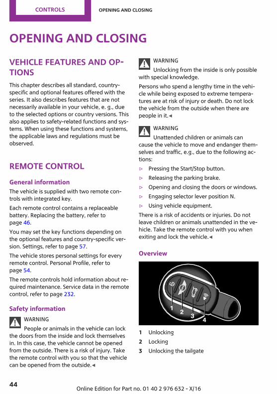
Overview
1 Unlocking2 Locking3 Unlocking the tailgate
Seite 44
CONTROLS Opening and closing
44 Online Edition for Part no. 01 40 2 976 632 - X/16
With automatic tailgate operation: open thetailgate
4 Panic mode
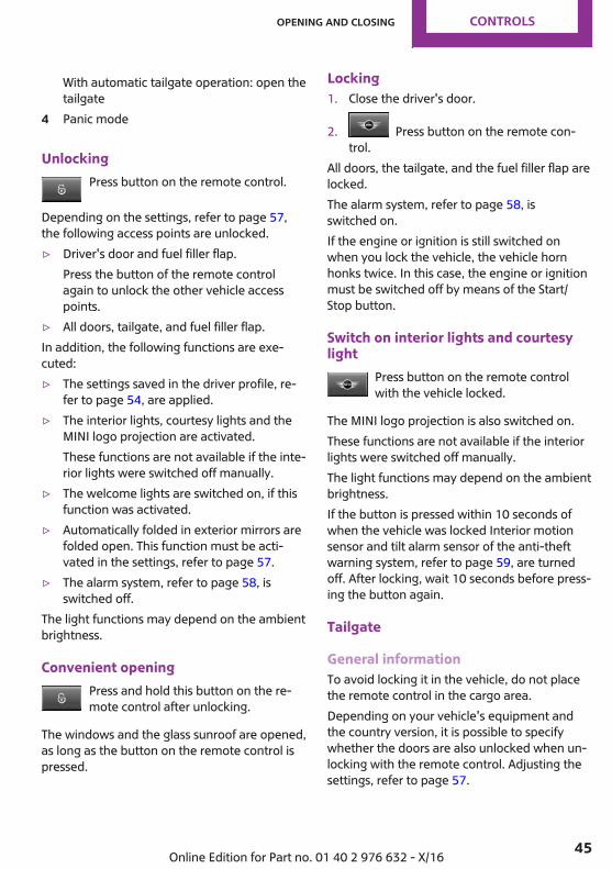
UnlockingPress button on the remote control.
Depending on the settings, refer to page 57,the following access points are unlocked.▷ Driver's door and fuel filler flap.
Press the button of the remote controlagain to unlock the other vehicle accesspoints.
▷ All doors, tailgate, and fuel filler flap.In addition, the following functions are exe‐cuted:▷ The settings saved in the driver profile, re‐
fer to page 54, are applied.▷ The interior lights, courtesy lights and the
MINI logo projection are activated.These functions are not available if the inte‐rior lights were switched off manually.
▷ The welcome lights are switched on, if thisfunction was activated.
▷ Automatically folded in exterior mirrors arefolded open. This function must be acti‐vated in the settings, refer to page 57.
▷ The alarm system, refer to page 58, isswitched off.
The light functions may depend on the ambientbrightness.
Convenient openingPress and hold this button on the re‐mote control after unlocking.
The windows and the glass sunroof are opened,as long as the button on the remote control ispressed.
Locking1. Close the driver's door.
2. Press button on the remote con‐trol.
All doors, the tailgate, and the fuel filler flap arelocked.The alarm system, refer to page 58, isswitched on.If the engine or ignition is still switched onwhen you lock the vehicle, the vehicle hornhonks twice. In this case, the engine or ignitionmust be switched off by means of the Start/Stop button.
Switch on interior lights and courtesylight
Press button on the remote controlwith the vehicle locked.
The MINI logo projection is also switched on.These functions are not available if the interiorlights were switched off manually.The light functions may depend on the ambientbrightness.If the button is pressed within 10 seconds ofwhen the vehicle was locked Interior motionsensor and tilt alarm sensor of the anti-theftwarning system, refer to page 59, are turnedoff. After locking, wait 10 seconds before press‐ing the button again.
Tailgate
General informationTo avoid locking it in the vehicle, do not placethe remote control in the cargo area.Depending on your vehicle's equipment andthe country version, it is possible to specifywhether the doors are also unlocked when un‐locking with the remote control. Adjusting thesettings, refer to page 57.
Seite 45
Opening and closing CONTROLS
45Online Edition for Part no. 01 40 2 976 632 - X/16

Safety informationWARNINGBody parts can be jammed when operat‐
ing the tailgate. There is a risk of injury. Makesure that the area of movement of the tailgateis clear during opening and closing.◀
NOTEThe tailgate swings back and up when it
opens. There is a risk of damage to property.Make sure that the area of movement of thetailgate is clear during opening and closing.◀
NOTESharp-edged or pointed objects can hit
the rear window and heat conductors whiledriving. There is a risk of property damage.Cover the edges and ensure that pointed ob‐jects do not hit the rear window.◀
OpeningPress and hold button on the remotecontrol for approx. 1 second.
Without automatic tailgate operation:The tailgate is unlocked and can be swung up‐ward.With automatic tailgate operation:The tailgate opens automatically.
Panic modeYou can trigger the alarm system if you findyourself in a dangerous situation.
Press button on the remote controland hold for at least 3 seconds.
To switch off the alarm: press any button.
Replacing the battery1. Remove the integrated key from the re‐
mote control, refer to page 48.2. Slide the integrated key into the opening
and raise the cover.
The battery compartment is accessible.
3. Slide the integrated key in the cover of thebattery compartment and raise the cover.
4. Push battery in the direction of the arrowusing a pointed object and lift it out.
5. Insert a type CR 2032 battery with the posi‐tive side facing up.
6. Insert lid and cover.7. Push the integrated key into the remote
control until it engages.Have old batteries disposed of by adealer’s service center or another quali‐fied service center or repair shop or
take them to a collection point.
Seite 46
CONTROLS Opening and closing
46 Online Edition for Part no. 01 40 2 976 632 - X/16
Additional remote controlsAdditional remote controls are available from adealer’s service center or another qualifiedservice center or repair shop.
Loss of the remote controlsA lost remote control can be blocked and re‐placed by a dealer’s service center or anotherqualified service center or repair shop.
Malfunction
General informationA Check Control message is displayed.Remote control detection by the vehicle maymalfunction under the following circumstances:▷ The battery of the remote control is dis‐
charged. Replacing the battery, refer topage 46.
▷ Interference of the radio connection fromtransmission towers or other equipmentwith high transmitting power.
▷ Shielding of the remote control due tometal objects.Do not transport the remote control to‐gether with metal objects.
▷ Interference of the radio connection frommobile phones or other electronic devicesin direct proximity to the remote control.Do not transport the remote control to‐gether with electronic devices.
▷ Interference of radio transmission by acharging process of mobile devices, for in‐stance charging of a mobile phone.
In the case of interference, the vehicle can beunlocked and locked from the outside with theintegrated key, refer to page 47.
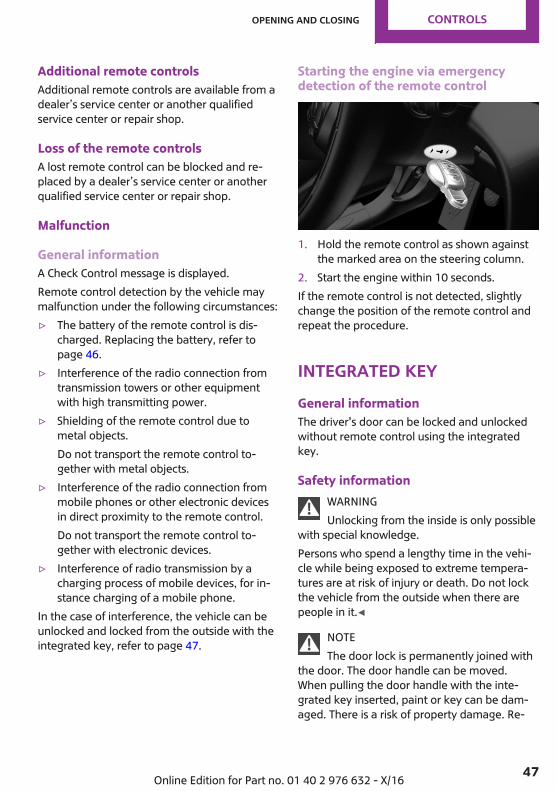
Starting the engine via emergencydetection of the remote control
1. Hold the remote control as shown againstthe marked area on the steering column.
2. Start the engine within 10 seconds.If the remote control is not detected, slightlychange the position of the remote control andrepeat the procedure.
Integrated keyGeneral informationThe driver's door can be locked and unlockedwithout remote control using the integratedkey.
Safety informationWARNINGUnlocking from the inside is only possible
with special knowledge.Persons who spend a lengthy time in the vehi‐cle while being exposed to extreme tempera‐tures are at risk of injury or death. Do not lockthe vehicle from the outside when there arepeople in it.◀
NOTEThe door lock is permanently joined with
the door. The door handle can be moved.When pulling the door handle with the inte‐grated key inserted, paint or key can be dam‐aged. There is a risk of property damage. Re‐
Seite 47
Opening and closing CONTROLS
47Online Edition for Part no. 01 40 2 976 632 - X/16

move the integrated key before pulling theoutside door handle.◀
Removing
Press the button, arrow 1, and pull out the inte‐grated key, arrow 2.
Locking/unlocking via the door lockUnlock or lock the driver's door via the doorlock using the integrated key. The other doorsmust be unlocked or locked from the inside.
1. Remove lid on the door lock.To do this, slide the integrated key into theopening from below and remove the lid.
2. Unlock or lock door lock.
Alarm systemThe alarm system is not switched on if the vehi‐cle is locked with the integrated key.The alarm system is triggered when the door isopened, if the vehicle has been unlocked viathe door lock. In order to stop this alarm, un‐lock vehicle with the remote control or switchon the ignition, if needed, through emergency
detection of the remote control, refer topage 47.
Buttons for the centrallocking systemGeneral informationIn the event of a severe accident, the vehicle isautomatically unlocked. The hazard warningsystem and interior lights come on.
Overview
Buttons for the central locking system.
LockingPress the button with the front doorsclosed.
▷ The fuel filler flap remains unlocked.▷ The vehicle is not secured against theft
when locking.
UnlockingPress button.
Opening
▷ Press button to unlock the doorstogether, and then pull the door handleabove the armrest.
Seite 48
CONTROLS Opening and closing
48 Online Edition for Part no. 01 40 2 976 632 - X/16
▷ Front doors: pull the door handle on thedoor to open the door. The other doors re‐main locked.
▷ Back doors: pull twice on the door handleon the door to be opened; the first time un‐locks the door, the second time opens it.The other doors remain locked.
Comfort AccessConceptThe vehicle can be accessed without activatingthe remote control.All you need to do is to have the remote controlwith you, such as in your pants pocket.The vehicle automatically detects the remotecontrol when it is in close proximity or in thevehicle's interior.
General informationTo avoid locking it in the vehicle, do not placethe remote control in the cargo area.Comfort Access supports the following func‐tions:▷ Unlocking and locking the vehicle.▷ Convenient closing.▷ Open the tailgate.▷ Opening/closing the tailgate with no-touch
activation.This function is not available in vehicleswith a trailer hitch or with a rear luggagerack preparation.
Functional requirements▷ To lock the vehicle, the remote control
must be located outside of the vehicle nearthe doors.
▷ The next unlocking and locking cycle is notpossible until after approx. 2 seconds.
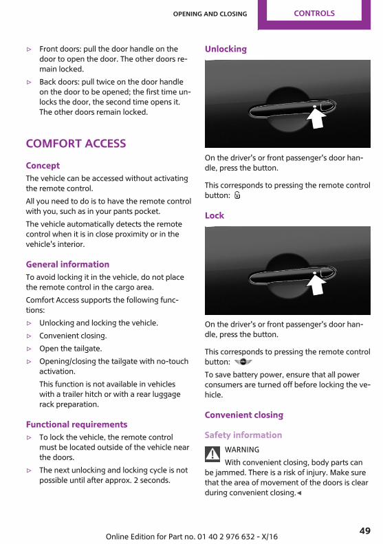
Unlocking
On the driver's or front passenger's door han‐dle, press the button.
This corresponds to pressing the remote controlbutton:
Lock
On the driver's or front passenger's door han‐dle, press the button.
This corresponds to pressing the remote controlbutton: To save battery power, ensure that all powerconsumers are turned off before locking the ve‐hicle.
Convenient closing
Safety informationWARNINGWith convenient closing, body parts can
be jammed. There is a risk of injury. Make surethat the area of movement of the doors is clearduring convenient closing.◀
Seite 49
Opening and closing CONTROLS
49Online Edition for Part no. 01 40 2 976 632 - X/16
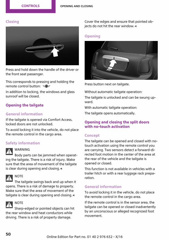
Closing
Press and hold down the handle of the driver orthe front seat passenger.
This corresponds to pressing and holding theremote control button: In addition to locking, the windows and glasssunroof will be closed.
Opening the tailgate
General informationIf the tailgate is opened via Comfort Access,locked doors are not unlocked.To avoid locking it into the vehicle, do not placethe remote control in the cargo area.
Safety informationWARNINGBody parts can be jammed when operat‐
ing the tailgate. There is a risk of injury. Makesure that the area of movement of the tailgateis clear during opening and closing.◀
NOTEThe tailgate swings back and up when it
opens. There is a risk of damage to property.Make sure that the area of movement of thetailgate is clear during opening and closing.◀
NOTESharp-edged or pointed objects can hit
the rear window and heat conductors whiledriving. There is a risk of property damage.
Cover the edges and ensure that pointed ob‐jects do not hit the rear window.◀
Opening
Press button next on tailgate.
Without automatic tailgate operation:The tailgate is unlocked and can be swung up‐ward.With automatic tailgate operation:The tailgate opens automatically.
Opening and closing the split doorswith no-touch activation
ConceptThe tailgate can be opened and closed with no-touch activation using the remote control youare carrying. Two sensors detect a forward-di‐rected foot motion in the center of the area atthe rear of the vehicle and the tailgate isopened or closed.This function is not available in vehicles with atrailer hitch or with a rear luggage rack prepa‐ration.
General informationTo avoid locking it in the vehicle, do not placethe remote control in the cargo area.If the remote control is in the sensor area, thetailgate can be opened or closed inadvertentlyby an unconscious or alleged recognized footmovement.
Seite 50
CONTROLS Opening and closing
50 Online Edition for Part no. 01 40 2 976 632 - X/16
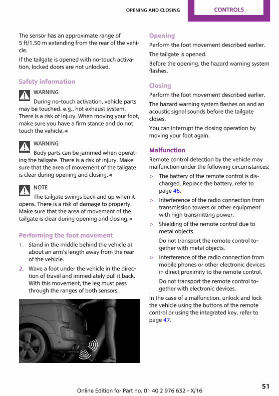
The sensor has an approximate range of5 ft/1.50 m extending from the rear of the vehi‐cle.If the tailgate is opened with no-touch activa‐tion, locked doors are not unlocked.
Safety informationWARNINGDuring no-touch activation, vehicle parts
may be touched, e.g., hot exhaust system.There is a risk of injury. When moving your foot,make sure you have a firm stance and do nottouch the vehicle.◀
WARNINGBody parts can be jammed when operat‐
ing the tailgate. There is a risk of injury. Makesure that the area of movement of the tailgateis clear during opening and closing.◀
NOTEThe tailgate swings back and up when it
opens. There is a risk of damage to property.Make sure that the area of movement of thetailgate is clear during opening and closing.◀
Performing the foot movement1. Stand in the middle behind the vehicle at
about an arm's length away from the rearof the vehicle.
2. Wave a foot under the vehicle in the direc‐tion of travel and immediately pull it back.With this movement, the leg must passthrough the ranges of both sensors.
OpeningPerform the foot movement described earlier.The tailgate is opened.Before the opening, the hazard warning systemflashes.
ClosingPerform the foot movement described earlier.The hazard warning system flashes on and anacoustic signal sounds before the tailgatecloses.You can interrupt the closing operation bymoving your foot again.
MalfunctionRemote control detection by the vehicle maymalfunction under the following circumstances:▷ The battery of the remote control is dis‐
charged. Replace the battery, refer topage 46.
▷ Interference of the radio connection fromtransmission towers or other equipmentwith high transmitting power.
▷ Shielding of the remote control due tometal objects.Do not transport the remote control to‐gether with metal objects.
▷ Interference of the radio connection frommobile phones or other electronic devicesin direct proximity to the remote control.Do not transport the remote control to‐gether with electronic devices.
In the case of a malfunction, unlock and lockthe vehicle using the buttons of the remotecontrol or using the integrated key, refer topage 47.
Seite 51
Opening and closing CONTROLS
51Online Edition for Part no. 01 40 2 976 632 - X/16
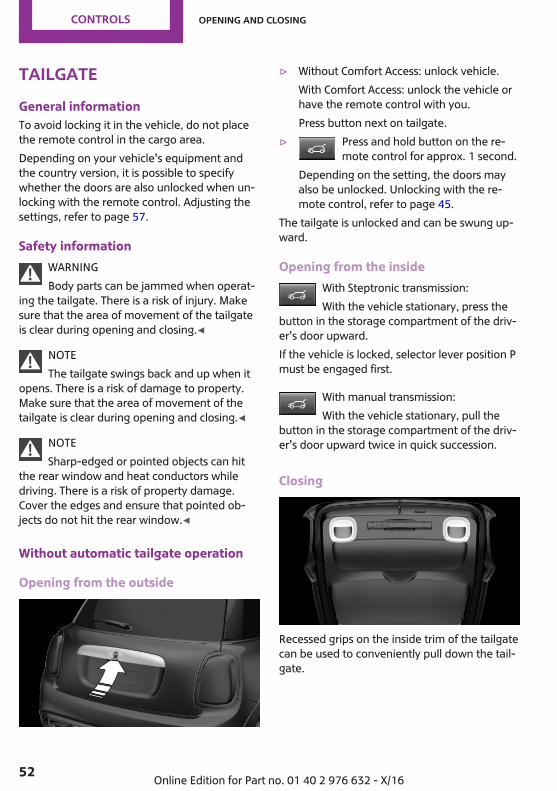
TailgateGeneral informationTo avoid locking it in the vehicle, do not placethe remote control in the cargo area.Depending on your vehicle's equipment andthe country version, it is possible to specifywhether the doors are also unlocked when un‐locking with the remote control. Adjusting thesettings, refer to page 57.
Safety informationWARNINGBody parts can be jammed when operat‐
ing the tailgate. There is a risk of injury. Makesure that the area of movement of the tailgateis clear during opening and closing.◀
NOTEThe tailgate swings back and up when it
opens. There is a risk of damage to property.Make sure that the area of movement of thetailgate is clear during opening and closing.◀
NOTESharp-edged or pointed objects can hit
the rear window and heat conductors whiledriving. There is a risk of property damage.Cover the edges and ensure that pointed ob‐jects do not hit the rear window.◀
Without automatic tailgate operation
Opening from the outside
▷ Without Comfort Access: unlock vehicle.With Comfort Access: unlock the vehicle orhave the remote control with you.Press button next on tailgate.
▷ Press and hold button on the re‐mote control for approx. 1 second.
Depending on the setting, the doors mayalso be unlocked. Unlocking with the re‐mote control, refer to page 45.
The tailgate is unlocked and can be swung up‐ward.
Opening from the insideWith Steptronic transmission:With the vehicle stationary, press the
button in the storage compartment of the driv‐er's door upward.If the vehicle is locked, selector lever position Pmust be engaged first.
With manual transmission:With the vehicle stationary, pull the
button in the storage compartment of the driv‐er's door upward twice in quick succession.
Closing
Recessed grips on the inside trim of the tailgatecan be used to conveniently pull down the tail‐gate.
Seite 52
CONTROLS Opening and closing
52 Online Edition for Part no. 01 40 2 976 632 - X/16
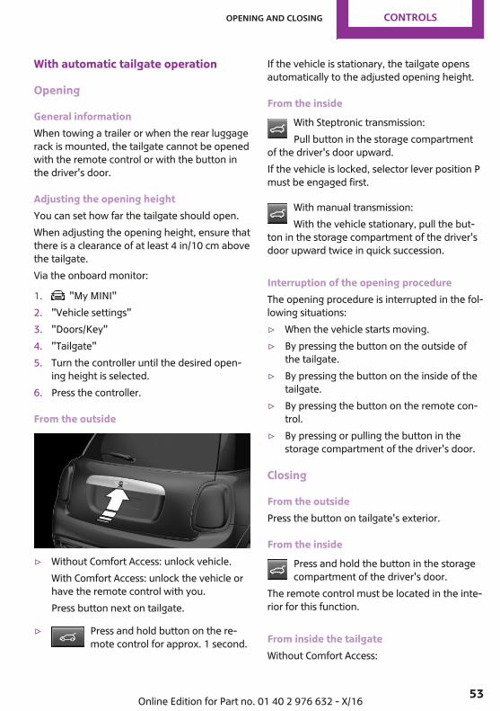
With automatic tailgate operation
Opening
General informationWhen towing a trailer or when the rear luggagerack is mounted, the tailgate cannot be openedwith the remote control or with the button inthe driver's door.
Adjusting the opening heightYou can set how far the tailgate should open.When adjusting the opening height, ensure thatthere is a clearance of at least 4 in/10 cm abovethe tailgate.Via the onboard monitor:
1. "My MINI"2. "Vehicle settings"3. "Doors/Key"4. "Tailgate"5. Turn the controller until the desired open‐
ing height is selected.6. Press the controller.
From the outside
▷ Without Comfort Access: unlock vehicle.With Comfort Access: unlock the vehicle orhave the remote control with you.Press button next on tailgate.
▷ Press and hold button on the re‐mote control for approx. 1 second.
If the vehicle is stationary, the tailgate opensautomatically to the adjusted opening height.
From the insideWith Steptronic transmission:Pull button in the storage compartment
of the driver's door upward.If the vehicle is locked, selector lever position Pmust be engaged first.
With manual transmission:With the vehicle stationary, pull the but‐
ton in the storage compartment of the driver'sdoor upward twice in quick succession.
Interruption of the opening procedureThe opening procedure is interrupted in the fol‐lowing situations:▷ When the vehicle starts moving.▷ By pressing the button on the outside of
the tailgate.▷ By pressing the button on the inside of the
tailgate.▷ By pressing the button on the remote con‐
trol.▷ By pressing or pulling the button in the
storage compartment of the driver's door.
Closing
From the outsidePress the button on tailgate's exterior.
From the insidePress and hold the button in the storagecompartment of the driver's door.
The remote control must be located in the inte‐rior for this function.
From inside the tailgateWithout Comfort Access:
Seite 53
Opening and closing CONTROLS
53Online Edition for Part no. 01 40 2 976 632 - X/16

Press button on the inside of the tailgate.
With Comfort Access:
▷ Press button, arrow 1, on the inside of thetailgate.
▷ Press button, arrow 2.The vehicle will be locked after closing thetailgate. The driver's door must be closedfor this purpose and the remote controlmust be outside of the vehicle in the areaof the tailgate.
Interruption of the closing procedureThe closing procedure is interrupted in the fol‐lowing situations:▷ If the vehicle starts off with a jerky move‐
ment.▷ By pressing the button on the outside of
the tailgate.▷ By pressing the button on the inside of the
tailgate.▷ By releasing the button in the storage com‐
partment of the driver's door.
Malfunction
Safety informationWARNINGWith manual operation of a blocked tail‐
gate, it can release itself unexpectedly from theblockage. There is a risk of injury or risk ofproperty damage. Do not operate the tailgatemanually if it is blocked. Have it checked by adealer’s service center or another qualifiedservice center or repair shop.◀
Manual operationOperate the unlocked tailgate manually with aslow and smooth motion.To close the tailgate fully, press down lightlyonly. Closing occurs automatically.
Driver profileConceptIn the driver profiles, individual settings for sev‐eral drivers can be stored and called up againwhen required.
General informationThere are three driver profiles with which per‐sonal vehicle settings can be stored. Every re‐mote control has one of these driver profilesassigned.If the vehicle is unlocked using a remote con‐trol, the assigned personal driver profile will beactivated. All settings stored in the driver profileare automatically applied.If several drivers use their own remote control,the vehicle will adjust the personal settings dur‐ing unlocking. These settings are also restored,if the vehicle has been used in the meantimeby a person with a different remote control.Changes to the settings are automatically savedin the driver profile currently activated.
Seite 54
CONTROLS Opening and closing
54 Online Edition for Part no. 01 40 2 976 632 - X/16
If another driver profile is selected via the on‐board monitor, the settings saved in it will beapplied automatically. The new driver profile isassigned to the remote control currently used.There is an additional guest profile availablethat is not assigned to any remote control: itcan be used to apply settings in the vehiclewithout changing the personal driver profiles.
Functional requirementsFor the system to be able to identify the driverprofile associated to a particular driver, the de‐tected remote control must be clearly allocatedto the driver.This is the case when:▷ The driver is only carrying his or her own re‐
mote control.▷ The driver unlocks the vehicle.▷ The driver gets into the vehicle through the
driver's door.
SettingsThe settings for the following systems and func‐tions are saved in the active profile. The scopeof storable settings depends on country andequipment.▷ Unlocking and locking.▷ Lights.▷ Radio.▷ Instrument cluster.▷ Programmable memory buttons.▷ Volumes, tone.▷ Control Display.▷ Climate control.▷ Navigation.▷ Park Distance Control PDC.▷ Rearview camera.▷ Head-up Display.▷ MINI Driving Modes.▷ Intelligent Safety.
Profile management
Selecting a driver profileRegardless of the remote control in use, a dif‐ferent driver profile may be activated. This al‐lows you to call up personal vehicle settings ifyou did not unlock the vehicle with your ownremote control.Via the onboard monitor:
1. "My MINI"2. "Driver profiles"3. Select driver profile.4. "OK"▷ All settings stored in the called-up driver
profile are automatically applied.▷ The called-up driver profile is assigned to
the remote control being used at the time.▷ If the driver profile is already assigned to a
different remote control, this driver profilewill apply to both remote controls.
Using a guest profileThe guest profile is for individual settings thatare stored in none of the three personal driverprofiles.This can be useful for drivers who are using thevehicle temporarily and do not have their owndriver profile.Via the onboard monitor:
1. "My MINI"2. "Driver profiles"3. "Drive off (guest)"4. "OK"The guest profile cannot be renamed. It is notassigned to the current remote control.
Renaming a driver profileA personal name can be assigned to the activedriver profile to avoid confusion between thedriver profiles.
Seite 55
Opening and closing CONTROLS
55Online Edition for Part no. 01 40 2 976 632 - X/16
Via the onboard monitor:
1. "My MINI"2. "Driver profiles"3. Select driver profile.
The driver profile marked with this sym‐bol can be renamed.
4. "Change driver profile name"5. Enter profile name.6. Select the symbol.
Resetting a driver profileThe settings of the active driver profile are resetto their factory settings.Via the onboard monitor:
1. "My MINI"2. "Driver profiles"
The driver profile marked with this sym‐bol can be reset.
3. Select driver profile.4. "Reset driver profile"5. "OK"
Exporting driver profilesMost settings of the active driver profile can beexported.This can be helpful for saving and retrievingpersonal settings, for instance before deliveringthe vehicle to a workshop. The saved driverprofiles can be taken into another vehicle.Export is made via the USB port to a USB stor‐age device.Popular file systems for USB media are sup‐ported. FAT32 and exFAT are the recom‐mended formats for profile export. Other for‐mats may not support the export.Via the onboard monitor:
1. "My MINI"2. "Driver profiles"3. Select driver profile.
The driver profile marked with this sym‐bol can be exported.
4. "Export driver profile (USB)"Select USB storage device as needed.
Importing driver profilesProfiles stored on a USB storage device can beimported via the USB interface.The existing settings of the active driver profileare overwritten with the settings of the im‐ported driver profile.Via the onboard monitor:
1. "My MINI"2. "Driver profiles"3. Select the driver profile to be overwritten.
The driver profile marked with this sym‐bol can be overwritten.
4. "Import driver profile (USB)"Select USB storage device as needed.
5. Select the driver profile to be imported.
Displaying driver profiles during startThe driver profiles can be displayed during eachstart to select the desired profile.Via the onboard monitor:
1. "My MINI"2. "Driver profiles"3. "Show driver profiles at startup"
System limitsA clear assignment between the remote controland driver may not be possible in the followingcases, for example.▷ The passenger unlocks the vehicle with his
or her own remote control, but anotherperson is driving.
▷ The driver unlocks the vehicle via ComfortAccess and has multiple remote controlswith him or her.
Seite 56
CONTROLS Opening and closing
56 Online Edition for Part no. 01 40 2 976 632 - X/16
▷ The driver changes, but the vehicle is notlocked and unlocked.
▷ Multiple remote controls are located out‐side of the vehicle.
SettingsGeneral informationDepending on your vehicle's equipment andthe country version, various settings for open‐ing and closing are possible.These settings are stored for the driver profile,refer to page 54, currently used.
Unlocking
DoorsVia the onboard monitor:
1. "My MINI"2. "Vehicle settings"3. "Doors/Key"4. "Driver's door" or "All doors"5. Select desired setting:
▷ "Driver's door only"Only the driver's door and the fuel fillerflap are unlocked. Pressing again un‐locks the entire vehicle.
▷ "All doors"The entire vehicle is unlocked.
TailgateVia the onboard monitor:
1. "My MINI"2. "Vehicle settings"3. "Doors/Key"4. "Tailgate" or "Tailgate and door(s)"5. Select desired setting:
▷ "Tailgate"
Only the tailgate is unlocked.▷ "Tailgate and door(s)"
The tailgate and the doors are un‐locked.
Depending on optional features and countryversion, this setting is not offered in somecases.
Automatic lockingVia the onboard monitor:
1. "My MINI"2. "Vehicle settings"3. "Doors/Key"4. Select desired setting:
▷ "Lock automatically"The vehicle locks automatically after ashort period of time if no door isopened after unlocking.
▷ "Lock after starting to drive"The vehicle locks automatically afteryou drive off.
Automatic unlockingVia the onboard monitor:
1. "My MINI"2. "Vehicle settings"3. "Doors/Key"4. "Unlock at end of trip"
After the engine is switched off by pressingthe Start/Stop button, the locked vehicle isautomatically unlocked.
Confirmation signals from the vehicleVia the onboard monitor:
1. "My MINI"2. "Vehicle settings"3. "Doors/Key"4. Deactivate or activate the desired confir‐
mation signals.
Seite 57
Opening and closing CONTROLS
57Online Edition for Part no. 01 40 2 976 632 - X/16
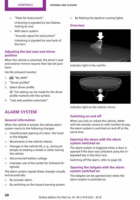
▷ "Flash for lock/unlock"Unlocking is signaled by two flashes,locking by one.
▷ With alarm system:"Acoustic signal for lock/unlock"Unlocking is signaled by one honk ofthe horn.
Adjusting the last seat and mirrorpositionWhen the vehicle is unlocked, the driver's seatand exterior mirrors resume their last set posi‐tions.Via the onboard monitor:
1. "My MINI"2. "Driver profiles"3. Select driver profile.
The setting can be made for the driverprofile marked with this symbol.
4. "Last seat position automatic"
Alarm systemGeneral informationWhen the vehicle is locked, the vehicle alarmsystem reacts to the following changes:▷ Unauthorized opening of a door, the hood
or the tailgate.▷ Movements in the vehicle interior.▷ Changes in the vehicle tilt, e. g., during at‐
tempts at stealing a wheel or when towingthe vehicle.
▷ Disconnected battery voltage.▷ Improper use of the socket for Onboard Di‐
agnosis.The alarm system signals these changes visuallyand acoustically:▷ By acoustic alarm.▷ By switching on the hazard warning system.
▷ By flashing the daytime running lights.
Overview
Indicator light in the roof fin.
Indicator light on the interior mirror.
Switching on and offWhen you lock or unlock the vehicle, eitherwith the remote control or with Comfort Access,the alarm system is switched on and off at thesame time.
Opening the doors with the alarmsystem switched onThe alarm system is triggered when a door isopened if the door was unlocked using the in‐tegrated key in the door lock.Switching off the alarm, refer to page 59.
Opening the tailgate with the alarmsystem switched onThe tailgate can be opened even when thealarm system is switched on.
Seite 58
CONTROLS Opening and closing
58 Online Edition for Part no. 01 40 2 976 632 - X/16

After the tailgate is closed, it is locked andmonitored again provided the doors arelocked. The hazard warning system flashesonce.
Panic modeYou can trigger the alarm system if you findyourself in a dangerous situation.
Press button on the remote control forat least 3 seconds.
To switch off the alarm: press any button.
Signals of the indicator lights▷ The indicator light flashes briefly every
2 seconds:The alarm system is switched on.
▷ Indicator light flashes for approx. 10 sec‐onds, then it flashes briefly every 2 sec‐onds:Interior motion sensor and tilt alarm sensorare not active, as doors, hood, or tailgateare not correctly closed. Correctly closedaccess points are secured.When the still open access points areclosed, interior motion sensor and tilt alarmsensor will be switched on.
▷ The indicator light goes out after unlocking:The vehicle has not been tampered with.
▷ The indicator light flashes after unlockinguntil the engine ignition is switched on, butno longer than approx. 5 minutes:An alarm has been triggered.
Tilt alarm sensorThe tilt of the vehicle is monitored.The alarm system responds in situations such asattempts to steal a wheel or when the vehicle istowed.
Interior motion sensorThe windows and the glass sunroof must beclosed for the system to function properly.
Avoiding unintentional alarms
General informationThe tilt alarm sensor and interior motion sensormay trigger the alarm even though no one istrying to gain unauthorized access.Possible situations for an unintended alarm:▷ In automatic vehicle washes.▷ In duplex garages.▷ During transport on trains carrying vehicles,
at sea or on a trailer.▷ With animals in the vehicle.For such situations, the tilt alarm sensor and in‐terior motion sensor can be switched off.
Switching off the tilt alarm sensor andinterior motion sensor
Press the remote control button againwithin 10 seconds as soon as the vehi‐
cle is locked.The indicator lamp lights up for approx. 2 sec‐onds and then continues to flash.The tilt alarm sensor and interior motion sensorare turned off until the vehicle is locked again.
Switching off the alarm▷ Unlock the vehicle with the remote control
or switch on the ignition, if needed throughemergency detection of remote control, re‐fer to page 47.
▷ With Comfort Access: If you have the re‐mote control with you, unlock the vehicleusing the button on the driver's side or pas‐senger side door.
Seite 59
Opening and closing CONTROLS
59Online Edition for Part no. 01 40 2 976 632 - X/16
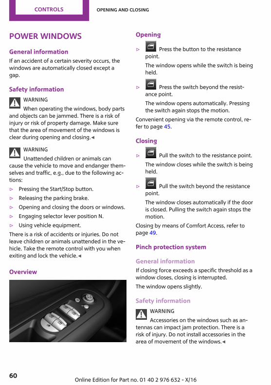
Power windowsGeneral informationIf an accident of a certain severity occurs, thewindows are automatically closed except agap.
Safety informationWARNINGWhen operating the windows, body parts
and objects can be jammed. There is a risk ofinjury or risk of property damage. Make surethat the area of movement of the windows isclear during opening and closing.◀
WARNINGUnattended children or animals can
cause the vehicle to move and endanger them‐selves and traffic, e.g., due to the following ac‐tions:▷ Pressing the Start/Stop button.▷ Releasing the parking brake.▷ Opening and closing the doors or windows.▷ Engaging selector lever position N.▷ Using vehicle equipment.There is a risk of accidents or injuries. Do notleave children or animals unattended in the ve‐hicle. Take the remote control with you whenexiting and lock the vehicle.◀
Overview
Opening
▷ Press the button to the resistancepoint.The window opens while the switch is beingheld.
▷ Press the switch beyond the resist‐ance point.The window opens automatically. Pressingthe switch again stops the motion.
Convenient opening via the remote control, re‐fer to page 45.
Closing
▷ Pull the switch to the resistance point.The window closes while the switch is beingheld.
▷ Pull the switch beyond the resistancepoint.The window closes automatically if the dooris closed. Pulling the switch again stops themotion.
Closing by means of Comfort Access, refer topage 49.
Pinch protection system
General informationIf closing force exceeds a specific threshold as awindow closes, closing is interrupted.The window opens slightly.
Safety informationWARNINGAccessories on the windows such as an‐
tennas can impact jam protection. There is arisk of injury. Do not install accessories in thearea of movement of the windows.◀
Seite 60
CONTROLS Opening and closing
60 Online Edition for Part no. 01 40 2 976 632 - X/16
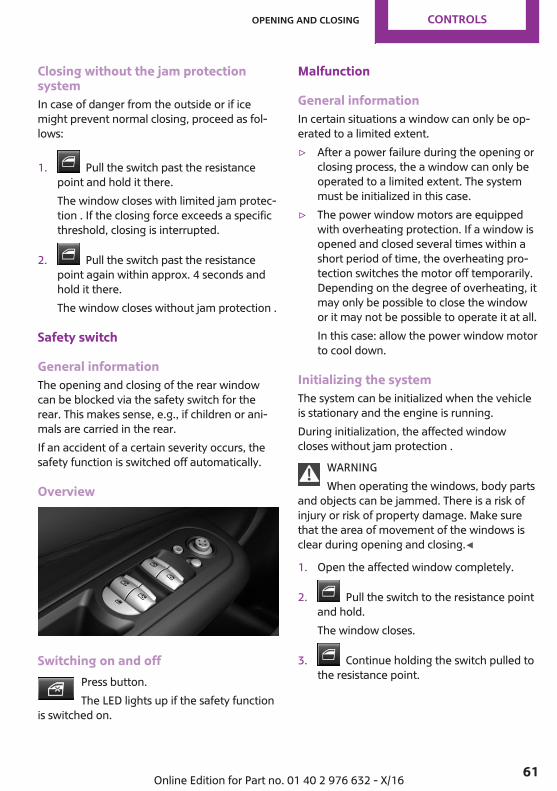
Closing without the jam protectionsystemIn case of danger from the outside or if icemight prevent normal closing, proceed as fol‐lows:
1. Pull the switch past the resistancepoint and hold it there.The window closes with limited jam protec‐tion . If the closing force exceeds a specificthreshold, closing is interrupted.
2. Pull the switch past the resistancepoint again within approx. 4 seconds andhold it there.The window closes without jam protection .
Safety switch
General informationThe opening and closing of the rear windowcan be blocked via the safety switch for therear. This makes sense, e.g., if children or ani‐mals are carried in the rear.If an accident of a certain severity occurs, thesafety function is switched off automatically.
Overview
Switching on and offPress button.The LED lights up if the safety function
is switched on.
Malfunction
General informationIn certain situations a window can only be op‐erated to a limited extent.▷ After a power failure during the opening or
closing process, the a window can only beoperated to a limited extent. The systemmust be initialized in this case.
▷ The power window motors are equippedwith overheating protection. If a window isopened and closed several times within ashort period of time, the overheating pro‐tection switches the motor off temporarily.Depending on the degree of overheating, itmay only be possible to close the windowor it may not be possible to operate it at all.In this case: allow the power window motorto cool down.
Initializing the systemThe system can be initialized when the vehicleis stationary and the engine is running.During initialization, the affected windowcloses without jam protection .
WARNINGWhen operating the windows, body parts
and objects can be jammed. There is a risk ofinjury or risk of property damage. Make surethat the area of movement of the windows isclear during opening and closing.◀
1. Open the affected window completely.
2. Pull the switch to the resistance pointand hold.The window closes.
3. Continue holding the switch pulled tothe resistance point.
Seite 61
Opening and closing CONTROLS
61Online Edition for Part no. 01 40 2 976 632 - X/16
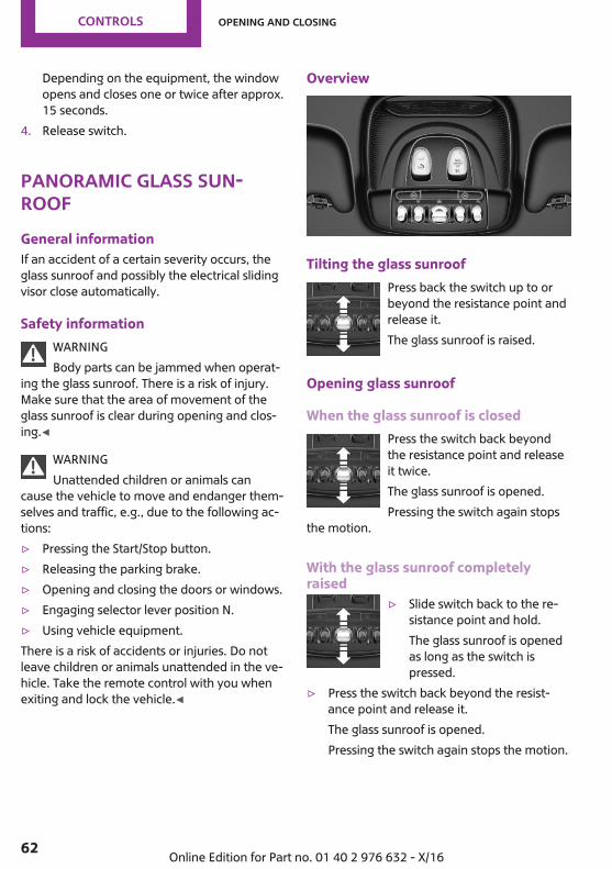
Depending on the equipment, the windowopens and closes one or twice after approx.15 seconds.
4. Release switch.
Panoramic glass sun‐roofGeneral informationIf an accident of a certain severity occurs, theglass sunroof and possibly the electrical slidingvisor close automatically.
Safety informationWARNINGBody parts can be jammed when operat‐
ing the glass sunroof. There is a risk of injury.Make sure that the area of movement of theglass sunroof is clear during opening and clos‐ing.◀
WARNINGUnattended children or animals can
cause the vehicle to move and endanger them‐selves and traffic, e.g., due to the following ac‐tions:▷ Pressing the Start/Stop button.▷ Releasing the parking brake.▷ Opening and closing the doors or windows.▷ Engaging selector lever position N.▷ Using vehicle equipment.There is a risk of accidents or injuries. Do notleave children or animals unattended in the ve‐hicle. Take the remote control with you whenexiting and lock the vehicle.◀
Overview
Tilting the glass sunroofPress back the switch up to orbeyond the resistance point andrelease it.The glass sunroof is raised.
Opening glass sunroof
When the glass sunroof is closedPress the switch back beyondthe resistance point and releaseit twice.The glass sunroof is opened.Pressing the switch again stops
the motion.
With the glass sunroof completelyraised
▷ Slide switch back to the re‐sistance point and hold.The glass sunroof is openedas long as the switch ispressed.
▷ Press the switch back beyond the resist‐ance point and release it.The glass sunroof is opened.Pressing the switch again stops the motion.
Seite 62
CONTROLS Opening and closing
62 Online Edition for Part no. 01 40 2 976 632 - X/16
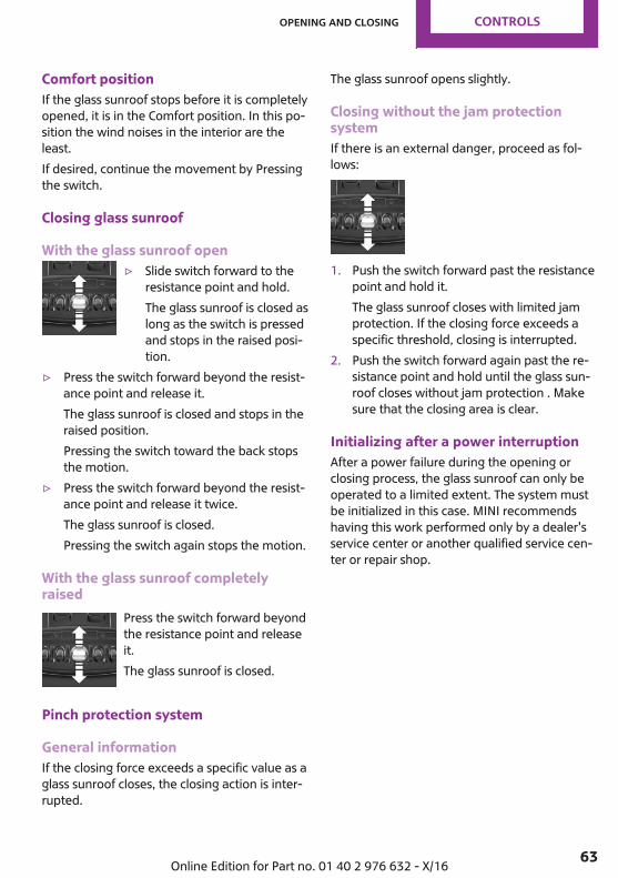
Comfort positionIf the glass sunroof stops before it is completelyopened, it is in the Comfort position. In this po‐sition the wind noises in the interior are theleast.If desired, continue the movement by Pressingthe switch.
Closing glass sunroof
With the glass sunroof open▷ Slide switch forward to the
resistance point and hold.The glass sunroof is closed aslong as the switch is pressedand stops in the raised posi‐tion.
▷ Press the switch forward beyond the resist‐ance point and release it.The glass sunroof is closed and stops in theraised position.Pressing the switch toward the back stopsthe motion.
▷ Press the switch forward beyond the resist‐ance point and release it twice.The glass sunroof is closed.Pressing the switch again stops the motion.
With the glass sunroof completelyraised
Press the switch forward beyondthe resistance point and releaseit.The glass sunroof is closed.
Pinch protection system
General informationIf the closing force exceeds a specific value as aglass sunroof closes, the closing action is inter‐rupted.
The glass sunroof opens slightly.
Closing without the jam protectionsystemIf there is an external danger, proceed as fol‐lows:
1. Push the switch forward past the resistancepoint and hold it.The glass sunroof closes with limited jamprotection. If the closing force exceeds aspecific threshold, closing is interrupted.
2. Push the switch forward again past the re‐sistance point and hold until the glass sun‐roof closes without jam protection . Makesure that the closing area is clear.
Initializing after a power interruptionAfter a power failure during the opening orclosing process, the glass sunroof can only beoperated to a limited extent. The system mustbe initialized in this case. MINI recommendshaving this work performed only by a dealer'sservice center or another qualified service cen‐ter or repair shop.
Seite 63
Opening and closing CONTROLS
63Online Edition for Part no. 01 40 2 976 632 - X/16
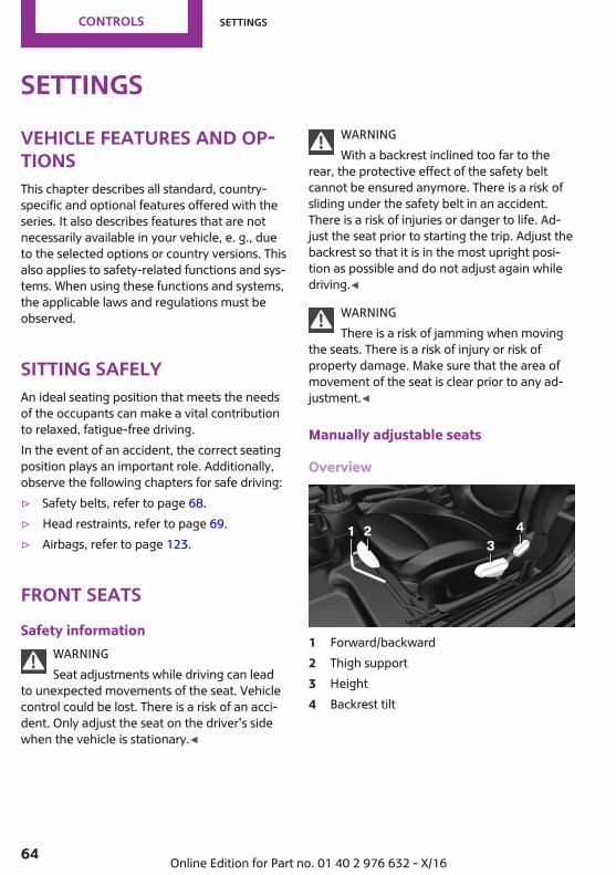
SettingsVehicle features and op‐tionsThis chapter describes all standard, country-specific and optional features offered with theseries. It also describes features that are notnecessarily available in your vehicle, e. g., dueto the selected options or country versions. Thisalso applies to safety-related functions and sys‐tems. When using these functions and systems,the applicable laws and regulations must beobserved.
Sitting safelyAn ideal seating position that meets the needsof the occupants can make a vital contributionto relaxed, fatigue-free driving.In the event of an accident, the correct seatingposition plays an important role. Additionally,observe the following chapters for safe driving:▷ Safety belts, refer to page 68.▷ Head restraints, refer to page 69.▷ Airbags, refer to page 123.
Front seatsSafety information
WARNINGSeat adjustments while driving can lead
to unexpected movements of the seat. Vehiclecontrol could be lost. There is a risk of an acci‐dent. Only adjust the seat on the driver's sidewhen the vehicle is stationary.◀
WARNINGWith a backrest inclined too far to the
rear, the protective effect of the safety beltcannot be ensured anymore. There is a risk ofsliding under the safety belt in an accident.There is a risk of injuries or danger to life. Ad‐just the seat prior to starting the trip. Adjust thebackrest so that it is in the most upright posi‐tion as possible and do not adjust again whiledriving.◀
WARNINGThere is a risk of jamming when moving
the seats. There is a risk of injury or risk ofproperty damage. Make sure that the area ofmovement of the seat is clear prior to any ad‐justment.◀
Manually adjustable seats
Overview
1 Forward/backward2 Thigh support3 Height4 Backrest tilt
Seite 64
CONTROLS Settings
64 Online Edition for Part no. 01 40 2 976 632 - X/16
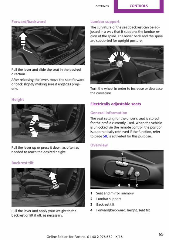
Forward/backward
Pull the lever and slide the seat in the desireddirection.After releasing the lever, move the seat forwardor back slightly making sure it engages prop‐erly.
Height
Pull the lever up or press it down as often asneeded to reach the desired height.
Backrest tilt
Pull the lever and apply your weight to thebackrest or lift it off, as necessary.
Lumbar supportThe curvature of the seat backrest can be ad‐justed in a way that it supports the lumbar re‐gion of the spine. The lower back and the spineare supported for upright posture.
Turn the wheel in order to increase or decreasethe curvature.
Electrically adjustable seats
General informationThe seat setting for the driver's seat is storedfor the profile currently used. When the vehicleis unlocked via the remote control, the positionis automatically retrieved if the function, referto page 58, is activated for this purpose.
Overview
1 Seat and mirror memory2 Lumbar support3 Backrest tilt4 Forward/backward, height, seat tilt
Seite 65
Settings CONTROLS
65Online Edition for Part no. 01 40 2 976 632 - X/16
Forward/backward
Push switch forward or backward.
Height
Push switch up or down.
Seat tilt
Move switch up or down.
Backrest tilt
Move switch forward or backward.
Lumbar support
ConceptThe curvature of the seat backrest can be ad‐justed in a way that it supports the lumbar re‐gion of the spine. The lower back and the spineare supported for upright posture.
Settings▷ Press the front/rear section
of the switch:The curvature is increased/decreased.
▷ Press the upper/lower sec‐tion of the switch:The curvature is shifted up/down.
Thigh support
Pull the lever at the front of the seat and adjustthe thigh support.
Seite 66
CONTROLS Settings
66 Online Edition for Part no. 01 40 2 976 632 - X/16

Front seat heating
Overview
Seat heating
Switching onPress button once for each tempera‐ture level.
The maximum temperature is reached whenthree LEDs are lit.If the trip is continued within approx. 15 mi‐nutes after a stop, seat heating is activated au‐tomatically with the temperature selected last.When GREEN Mode, refer to page 196, is acti‐vated, the heater output is reduced.
Switching offPress and hold the button, until theLEDs go out.
Rear seatsSafety information
WARNINGThere is a risk of jamming when folding
down the center armrest in the rear. There is arisk of injury. Make sure that the area of move‐ment of the center armrest is clear during fold‐ing down.◀
WARNINGUnexpected movements of the backrest
while driving may occur due to unintentionalunlocking of the rear backrests by the straps.There is a risk of injury. Do not fasten any ob‐jects to the straps for unlocking the rear backr‐ests.◀
Forward/backward
General informationThe rear seat is divided at a ratio of 60 to 40.The left seat is connected to the center section.
Settings
Pull the lever and slide the seat in the desireddirection.After releasing the lever, move the seat forwardor back slightly making sure it engages prop‐erly.
Backrest tilt
Pull the strap and apply your weight to thebackrest or lift it off, as necessary.
Seite 67
Settings CONTROLS
67Online Edition for Part no. 01 40 2 976 632 - X/16
Safety beltsNumber of safety beltsThe vehicle is fitted with five safety belts to en‐sure occupant safety. However, they can onlyoffer protection when adjusted correctly.The two outer safety belt buckles of the rearseat are intended for the persons sitting on theleft and right.The center safety belt buckle of the rear seat isintended for the person sitting in the middle.
General informationAlways make sure that safety belts are beingworn by all occupants before driving off. Al‐though airbags enhance safety by providingadded protection, they are not a substitute forsafety belts.Slowly guide the safety belt out of the holderwhen fastening it.If needed, disengage the safety belt in the rearfrom the belt buckle on the side.The upper shoulder strap's anchorage point willbe correct for adult seat occupants of everybuild if the seat is correctly adjusted.
Safety informationWARNINGIf the safety belt is used to buckle more
than one person, the protective effect of thesafety belt can no longer be ensured. There is arisk of injuries or danger to life. Do not allowmore than one person to wear a single safetybelt. Infants and children are not allowed on anoccupant's lap, but must be transported andsecured in designated child restraint systems.◀
WARNINGThe protective effect of the safety belts
can be limited or lost when safety belts are fas‐tened incorrectly. An incorrectly fastened safetybelt can cause additional injuries, e.g., in theevent of an accident or during braking and eva‐
sive maneuvers. There is a risk of injuries ordanger to life. Make sure that all occupants arewearing safety belts correctly.◀
WARNINGThe protective effect of the safety belts
may not be fully functional or fail in the follow‐ing situations:▷ Safety belts are damaged, soiled or
changed in any other way.▷ Safety belt buckle is damaged or heavily
soiled.▷ Belt tensioners or belt retractors were
modified.Safety belts can be imperceptibly damaged inthe event of an accident. There is a risk of inju‐ries or danger to life. Do not modify safetybelts, safety belt buckles, belt tensioners, beltretractors or belt anchors and keep them clean.Have the safety belts checked after an accidentat the dealer’s service center or another quali‐fied service center or repair shop.◀
Correct use of safety belts▷ Wear the safety belt twist-free and as tight
to your body as possible over your lap andshoulders.
▷ Wear the safety belt deep on your hips overyour lap. The safety belt may not press onyour stomach.
▷ Do not rub the safety belt against sharpedges, or guide it or jam it in across hard orfragile objects.
▷ Avoid thick clothing.▷ Re-tighten the safety belt frequently up‐
ward around your upper body.
Seite 68
CONTROLS Settings
68 Online Edition for Part no. 01 40 2 976 632 - X/16
Buckling the seat belt
Make sure you hear the latch plate engage inthe belt buckle.
Unbuckling the safety belt1. Hold the safety belt firmly.2. Press the red button in the belt buckle.3. Guide the safety belt back into its roll-up
mechanism.
Middle safety belt in the rear
Buckling the safety belt
1. Pull the buckle tongues out of the mountsin the roof.
2. Insert the lower buckle tongue in the beltbuckle, arrow 1.
3. Insert the upper buckle tongue in the beltbuckle, arrow 2.Safety belt buckles must audibly click intoplace.
Unbuckling the safety belt1. Hold the safety belt firmly.2. Press the red button in the belt buckle.3. With the buckle tongue, arrow 1, open the
second safety belt buckle, arrow 2.
4. Guide the safety belt to the mount in theroofliner.
Safety belt reminder for driver's seatand front passenger seat
The indicator lamp lights up and a sig‐nal sounds. Make sure that the safetybelts are positioned correctly. The
safety belt reminder is active at speeds aboveapprox. 6 mph/10 km/h. It can also be acti‐vated if objects are placed on the front passen‐ger seat.
Front head restraintsCorrectly adjusted head restraint
General informationA correctly adjusted head restraint reduces therisk of injury to cervical vertebrae in the eventof an accident.
HeightAdjust the head restraint so that its center isapproximately at eye level.
Seite 69
Settings CONTROLS
69Online Edition for Part no. 01 40 2 976 632 - X/16
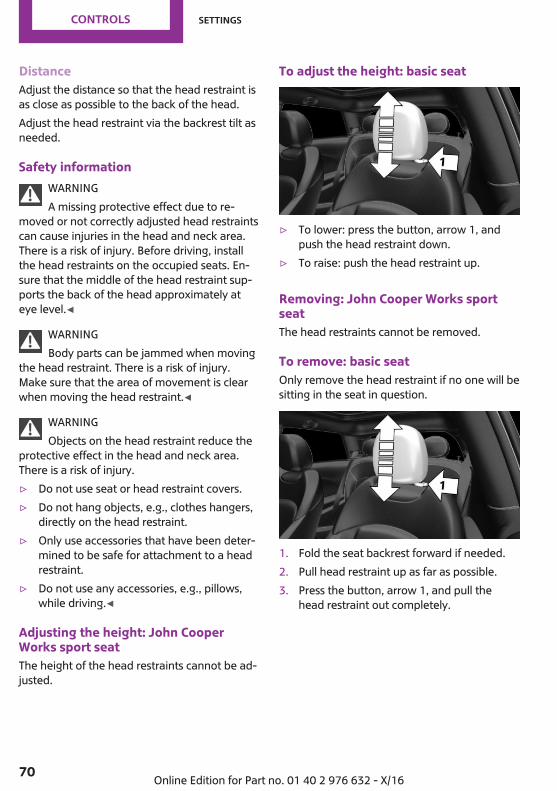
DistanceAdjust the distance so that the head restraint isas close as possible to the back of the head.Adjust the head restraint via the backrest tilt asneeded.
Safety informationWARNINGA missing protective effect due to re‐
moved or not correctly adjusted head restraintscan cause injuries in the head and neck area.There is a risk of injury. Before driving, installthe head restraints on the occupied seats. En‐sure that the middle of the head restraint sup‐ports the back of the head approximately ateye level.◀
WARNINGBody parts can be jammed when moving
the head restraint. There is a risk of injury.Make sure that the area of movement is clearwhen moving the head restraint.◀
WARNINGObjects on the head restraint reduce the
protective effect in the head and neck area.There is a risk of injury.▷ Do not use seat or head restraint covers.▷ Do not hang objects, e.g., clothes hangers,
directly on the head restraint.▷ Only use accessories that have been deter‐
mined to be safe for attachment to a headrestraint.
▷ Do not use any accessories, e.g., pillows,while driving.◀
Adjusting the height: John CooperWorks sport seatThe height of the head restraints cannot be ad‐justed.
To adjust the height: basic seat
▷ To lower: press the button, arrow 1, andpush the head restraint down.
▷ To raise: push the head restraint up.
Removing: John Cooper Works sportseatThe head restraints cannot be removed.
To remove: basic seatOnly remove the head restraint if no one will besitting in the seat in question.
1. Fold the seat backrest forward if needed.2. Pull head restraint up as far as possible.3. Press the button, arrow 1, and pull the
head restraint out completely.
Seite 70
CONTROLS Settings
70 Online Edition for Part no. 01 40 2 976 632 - X/16

Rear head restraintsCorrectly adjusted head restraint
General informationA correctly adjusted head restraint reduces therisk of injury to cervical vertebrae in the eventof an accident.
HeightAdjust the head restraint so that its center isapproximately at eye level.
Safety informationWARNINGA missing protective effect due to re‐
moved or not correctly adjusted head restraintscan cause injuries in the head and neck area.There is a risk of injury. Before driving, installthe head restraints on the occupied seats. En‐sure that the middle of the head restraint sup‐ports the back of the head approximately ateye level.◀
WARNINGBody parts can be jammed when moving
the head restraint. There is a risk of injury.Make sure that the area of movement is clearwhen moving the head restraint.◀
WARNINGObjects on the head restraint reduce the
protective effect in the head and neck area.There is a risk of injury.▷ Do not use seat or head restraint covers.▷ Do not hang objects, e.g., clothes hangers,
directly on the head restraint.▷ Only use accessories that have been deter‐
mined to be safe for attachment to a headrestraint.
▷ Do not use any accessories, e.g., pillows,while driving.◀
Adjusting the height
▷ To lower: press the button, arrow 1, andpush the head restraint down.
▷ To raise: push the head restraint up.
Fold down
▷ To fold down: press the button, arrow 1,and press down the head restraint, arrow 2.
▷ To fold up: pull up head restraints.
RemovingOnly remove the head restraint if no one will besitting in the seat in question.
1. Fold down the rear seat backrest, refer topage 183, in question.
Seite 71
Settings CONTROLS
71Online Edition for Part no. 01 40 2 976 632 - X/16
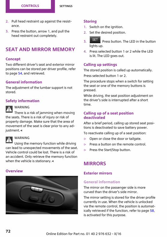
2. Pull head restraint up against the resist‐ance.
3. Press the button, arrow 1, and pull thehead restraint out completely.
Seat and mirror memoryConceptTwo different driver's seat and exterior mirrorpositions can be stored per driver profile, referto page 54, and retrieved.
General informationThe adjustment of the lumbar support is notstored.
Safety informationWARNINGThere is a risk of jamming when moving
the seats. There is a risk of injury or risk ofproperty damage. Make sure that the area ofmovement of the seat is clear prior to any ad‐justment.◀
WARNINGUsing the memory function while driving
can lead to unexpected movements of the seat.Vehicle control could be lost. There is a risk ofan accident. Only retrieve the memory functionwhen the vehicle is stationary.◀
Overview
Storing1. Switch on the ignition.2. Set the desired position.
3. Press button. The LED in the buttonlights up.
4. Press selected button 1 or 2 while the LEDis lit. The LED goes out.
Calling up settingsThe stored position is called up automatically.Press selected button 1 or 2.The procedure stops when a switch for settingthe seat or one of the memory buttons ispressed.While driving, the seat position adjustment onthe driver's side is interrupted after a shorttime.
Calling up of a seat positiondeactivatedAfter a brief period, calling up stored seat posi‐tions is deactivated to save battery power.To reactivate calling up of a seat position:▷ Open or close the door or tailgate.▷ Press a button on the remote control.▷ Press the Start/Stop button.
MirrorsExterior mirrors
General informationThe mirror on the passenger side is morecurved than the driver's side mirror.The mirror setting is stored for the driver profilecurrently in use. When the vehicle is unlockedvia the remote control, the position is automat‐ically retrieved if the function, refer to page 58,is activated for this purpose.
Seite 72
CONTROLS Settings
72 Online Edition for Part no. 01 40 2 976 632 - X/16
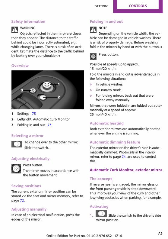
Safety informationWARNINGObjects reflected in the mirror are closer
than they appear. The distance to the trafficbehind could be incorrectly estimated, e.g.,while changing lanes. There is a risk of an acci‐dent. Estimate the distance to the traffic behindby looking over your shoulder.◀
Overview
1 Settings 732 Left/right, Automatic Curb Monitor3 Folding in and out 73
Selecting a mirrorTo change over to the other mirror:Slide the switch.
Adjusting electricallyPress button.The mirror moves in accordance withthe button movement.
Saving positionsThe current exterior mirror position can bestored via the seat and mirror memory, refer topage 72.
Adjusting manuallyIn case of an electrical malfunction, press theedges of the mirror.
Folding in and outNOTEDepending on the vehicle width, the ve‐
hicle can be damaged in vehicle washes. Thereis a risk of property damage. Before washing,fold in the mirrors by hand or with the button.◀
Press button.
Possible at speeds up to approx.15 mph/20 km/h.Fold the mirrors in and out is advantageous inthe following situations:▷ In vehicle washes.▷ On narrow roads.▷ For folding mirrors back out that were
folded away manually.Mirrors that were folded in are folded out auto‐matically at a speed of approx.25 mph/40 km/h.
Automatic heatingBoth exterior mirrors are automatically heatedwhenever the engine is running.
Automatic dimming featureThe exterior mirror on the driver's side is auto‐matically dimmed. Photocells in the interiormirror, refer to page 74, are used to controlthis.
Automatic Curb Monitor, exterior mirror
The conceptIf reverse gear is engaged, the mirror glass onthe front passenger side is tilted downward.This improves your view of the curb and otherlow-lying obstacles when parking, for example.
Activating
1. Slide the switch to the driver's sidemirror position.
Seite 73
Settings CONTROLS
73Online Edition for Part no. 01 40 2 976 632 - X/16
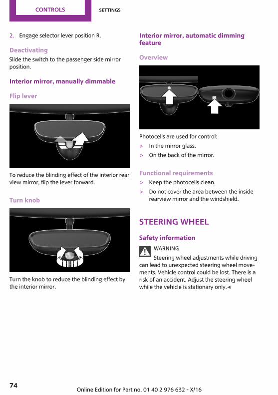
2. Engage selector lever position R.
DeactivatingSlide the switch to the passenger side mirrorposition.
Interior mirror, manually dimmable
Flip lever
To reduce the blinding effect of the interior rearview mirror, flip the lever forward.
Turn knob
Turn the knob to reduce the blinding effect bythe interior mirror.
Interior mirror, automatic dimmingfeature
Overview
Photocells are used for control:▷ In the mirror glass.▷ On the back of the mirror.
Functional requirements▷ Keep the photocells clean.▷ Do not cover the area between the inside
rearview mirror and the windshield.
Steering wheelSafety information
WARNINGSteering wheel adjustments while driving
can lead to unexpected steering wheel move‐ments. Vehicle control could be lost. There is arisk of an accident. Adjust the steering wheelwhile the vehicle is stationary only.◀
Seite 74
CONTROLS Settings
74 Online Edition for Part no. 01 40 2 976 632 - X/16
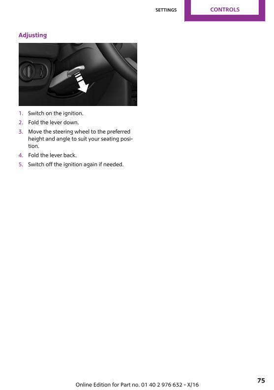
Adjusting
1. Switch on the ignition.2. Fold the lever down.3. Move the steering wheel to the preferred
height and angle to suit your seating posi‐tion.
4. Fold the lever back.5. Switch off the ignition again if needed.
Seite 75
Settings CONTROLS
75Online Edition for Part no. 01 40 2 976 632 - X/16

Transporting children safelyVehicle features and op‐tionsThis chapter describes all standard, country-specific and optional features offered with theseries. It also describes features that are not
necessarily available in your vehicle, e. g., dueto the selected options or country versions. Thisalso applies to safety-related functions and sys‐tems. When using these functions and systems,the applicable laws and regulations must beobserved.
The right place for childrenSafety information
WARNINGUnattended children or animals can
cause the vehicle to move and endanger them‐selves and traffic, e.g., due to the following ac‐tions:▷ Pressing the Start/Stop button.▷ Releasing the parking brake.▷ Opening and closing the doors or windows.▷ Engaging selector lever position N.▷ Using vehicle equipment.There is a risk of accidents or injuries. Do notleave children or animals unattended in the ve‐hicle. Take the remote control with you whenexiting and lock the vehicle.◀
Always transport children in the rearseat
General informationAccident research shows that the safest placefor children is in the rear seat.Transport children younger than 13 years ofage or shorter than 5 ft/150 cm only in the rearseat in suitable child restraint systems designedfor the age, weight and size of the child. Chil‐dren 13 years of age or older must wear asafety belt as soon as a suitable child restraint
system can no longer be used due to their age,weight and size.
Safety informationWARNINGThe safety belt cannot be fastened cor‐
rectly on children shorter than 5 ft, 150 cmwithout suitable additional child restraint sys‐tems. The protective effect of the safety beltscan be limited or lost when safety belts are fas‐tened incorrectly. An incorrectly fastened safetybelt can cause additional injuries, for instancein the event of an accident or during brakingand evasive maneuvers. There is a risk of inju‐ries or danger to life. Secure children shorterthan 5 ft, 150 cm using suitable child restraintsystems.◀
Children on the front passenger seat
General informationBefore using a child restraint system on thefront passenger seat, ensure that the front,knee, and side airbags on the front passengerside are deactivated. Automatic deactivation offront-seat passenger airbags, refer topage 125.
Seite 76
CONTROLS Transporting children safely
76 Online Edition for Part no. 01 40 2 976 632 - X/16
Safety informationWARNINGActive front-seat passenger airbags can
injure a child in a child restraint system whenthe airbags are activated. There is a risk of in‐jury. Make sure that the front-seat passengerairbags are deactivated and that the PASSEN‐GER AIRBAG OFF indicator lamp lights up.◀
WARNINGThe stability of the child restraint system
is limited or compromised with incorrect seatadjustment or improper installation of the childseat. There is a risk of injuries or danger to life.Make sure that the child restraint system fitssecurely against the backrest. If possible, adjustthe backrest tilt for all affected backrests andcorrectly adjust the seats. Make sure that seatsand backrests are securely engaged. If possible,adjust the height of the head restraints or re‐move them.◀
Installing child re‐straint systemsGeneral informationPay attention to the specifications of the childrestraint system manufacturer when selecting,installing, and using child restraint systems.In order to faciliate the installation of a back-facing child restraint system in the rear:Move the front passenger's seat as far up aspossible before folding down the backrest.
Safety informationWARNINGThe stability of the child restraint system
is limited or compromised with incorrect seatadjustment or improper installation of the childseat. There is a risk of injuries or danger to life.Make sure that the child restraint system fitssecurely against the backrest. If possible, adjust
the backrest tilt for all affected backrests andcorrectly adjust the seats. Make sure that seatsand backrests are securely engaged. If possible,adjust the height of the head restraints or re‐move them.◀
On the rear seatsIf the vehicle is equipped with a sliding rearseat row: move the seats to the rearmost posi‐tion before mounting a child restraint system.
On the front passenger seat
Deactivating airbagsWARNINGActive front-seat passenger airbags can
injure a child in a child restraint system whenthe airbags are activated. There is a risk of in‐jury. Make sure that the front-seat passengerairbags are deactivated and that the PASSEN‐GER AIRBAG OFF indicator lamp lights up.◀
After installing a child restraint system in thefront passenger seat, make sure that the front,knee and side airbags on the front passengerside are deactivated.Deactivate the front-seat passenger airbags au‐tomatically, refer to page 125.
Seat position and heightBefore installing a child restraint system, movethe front passenger seat as far back as possibleand adjust its height to the highest and thusbest possible position for the belt and to offeroptimal protection in the event of an accident.If the upper anchorage of the safety belt is lo‐cated in front of the belt guide of the child seat,move the passenger seat carefully forward untilthe best possible belt guide position is reached.
Seite 77
Transporting children safely CONTROLS
77Online Edition for Part no. 01 40 2 976 632 - X/16
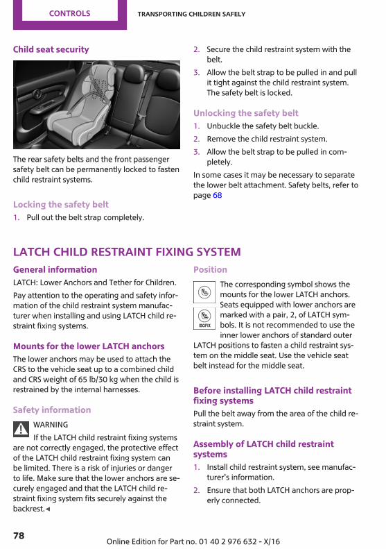
Child seat security
The rear safety belts and the front passengersafety belt can be permanently locked to fastenchild restraint systems.
Locking the safety belt1. Pull out the belt strap completely.
2. Secure the child restraint system with thebelt.
3. Allow the belt strap to be pulled in and pullit tight against the child restraint system.The safety belt is locked.
Unlocking the safety belt1. Unbuckle the safety belt buckle.2. Remove the child restraint system.3. Allow the belt strap to be pulled in com‐
pletely.In some cases it may be necessary to separatethe lower belt attachment. Safety belts, refer topage 68
LATCH child restraint fixing systemGeneral informationLATCH: Lower Anchors and Tether for Children.Pay attention to the operating and safety infor‐mation of the child restraint system manufac‐turer when installing and using LATCH child re‐straint fixing systems.
Mounts for the lower LATCH anchorsThe lower anchors may be used to attach theCRS to the vehicle seat up to a combined childand CRS weight of 65 lb/30 kg when the child isrestrained by the internal harnesses.
Safety informationWARNINGIf the LATCH child restraint fixing systems
are not correctly engaged, the protective effectof the LATCH child restraint fixing system canbe limited. There is a risk of injuries or dangerto life. Make sure that the lower anchors are se‐curely engaged and that the LATCH child re‐straint fixing system fits securely against thebackrest.◀
PositionThe corresponding symbol shows themounts for the lower LATCH anchors.Seats equipped with lower anchors aremarked with a pair, 2, of LATCH sym‐bols. It is not recommended to use theinner lower anchors of standard outer
LATCH positions to fasten a child restraint sys‐tem on the middle seat. Use the vehicle seatbelt instead for the middle seat.
Before installing LATCH child restraintfixing systemsPull the belt away from the area of the child re‐straint system.
Assembly of LATCH child restraintsystems1. Install child restraint system, see manufac‐
turer's information.2. Ensure that both LATCH anchors are prop‐
erly connected.
Seite 78
CONTROLS Transporting children safely
78 Online Edition for Part no. 01 40 2 976 632 - X/16
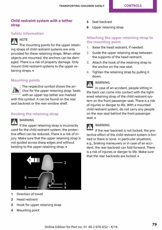
Child restraint system with a tetherstrap
Safety informationNOTEThe mounting points for the upper retain‐
ing straps of child restraint systems are onlyprovided for these retaining straps. When otherobjects are mounted, the anchors can be dam‐aged. There is a risk of property damage. Onlymount child restraint systems to the upper re‐taining straps.◀
Mounting pointsThe respective symbol shows the an‐chor for the upper retaining strap. Seatswith an upper top tether are marked
with this symbol. It can be found on the rearseat backrest or the rear window shelf.
Routing the retaining strapWARNINGIf the upper retaining strap is incorrectly
used for the child restraint system, the protec‐tive effect can be reduced. There is a risk of in‐jury. Make sure that the upper retaining strap isnot guided across sharp edges and withouttwisting to the upper retaining strap.◀
1 Direction of travel2 Head restraint3 Hook for upper retaining strap4 Mounting point
5 Seat backrest6 Upper retaining strap
Attaching the upper retaining strap tothe mounting point1. Raise the head restraint, if needed.2. Guide the upper retaining strap between
the supports of the head restraint.3. Attach the hook of the retaining strap to
the anchor on the rear seat.4. Tighten the retaining strap by pulling it
down.WARNINGIn case of an accident, people sitting in
the back can come into contact with the tight‐ened retaining strap of the child restraint sys‐tem on the front passenger seat. There is a riskof injuries or danger to life. With a mountedchild restraint system, do not carry any peopleon the rear seat behind the front passengerseat.◀
WARNINGIf the rear backrest is not locked, the pro‐
tective effect of the child restraint system is lim‐ited or there is none. In particular situations,e.g., braking maneuvers or in case of an acci‐dent, the rear backrest can fold forward. Thereis a risk of injuries or danger to life. Make surethat the rear backrests are locked.◀
Seite 79
Transporting children safely CONTROLS
79Online Edition for Part no. 01 40 2 976 632 - X/16
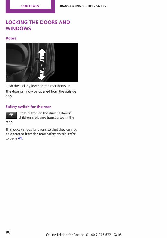
Locking the doors andwindowsDoors
Push the locking lever on the rear doors up.The door can now be opened from the outsideonly.
Safety switch for the rearPress button on the driver's door ifchildren are being transported in the
rear.
This locks various functions so that they cannotbe operated from the rear: safety switch, referto page 61.
Seite 80
CONTROLS Transporting children safely
80 Online Edition for Part no. 01 40 2 976 632 - X/16
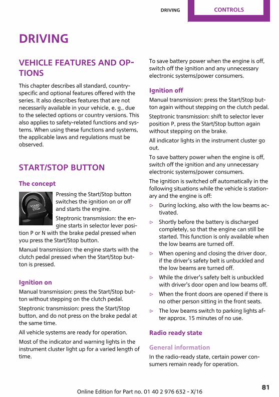
DrivingVehicle features and op‐tionsThis chapter describes all standard, country-specific and optional features offered with theseries. It also describes features that are notnecessarily available in your vehicle, e. g., dueto the selected options or country versions. Thisalso applies to safety-related functions and sys‐tems. When using these functions and systems,the applicable laws and regulations must beobserved.
Start/Stop buttonThe concept
Pressing the Start/Stop buttonswitches the ignition on or offand starts the engine.Steptronic transmission: the en‐gine starts in selector lever posi‐
tion P or N with the brake pedal pressed whenyou press the Start/Stop button.Manual transmission: the engine starts with theclutch pedal pressed when the Start/Stop but‐ton is pressed.
Ignition onManual transmission: press the Start/Stop but‐ton without stepping on the clutch pedal.Steptronic transmission: press the Start/Stopbutton, and do not press on the brake pedal atthe same time.All vehicle systems are ready for operation.Most of the indicator and warning lights in theinstrument cluster light up for a varied length oftime.
To save battery power when the engine is off,switch off the ignition and any unnecessaryelectronic systems/power consumers.
Ignition offManual transmission: press the Start/Stop but‐ton again without stepping on the clutch pedal.Steptronic transmission: shift to selector leverposition P, press the Start/Stop button againwithout stepping on the brake.All indicator lights in the instrument cluster goout.To save battery power when the engine is off,switch off the ignition and any unnecessaryelectronic systems/power consumers.The ignition is switched off automatically in thefollowing situations while the vehicle is station‐ary and the engine is off:▷ During locking, also with the low beams ac‐
tivated.▷ Shortly before the battery is discharged
completely, so that the engine can still bestarted. This function is only available whenthe low beams are turned off.
▷ When opening and closing the driver door,if the driver's safety belt is unbuckled andthe low beams are turned off.
▷ While the driver's safety belt is unbuckledwith driver's door open and low beams off.
▷ When the front doors are opened if there isno other person sitting in the front seats.
▷ The low beams switch to parking lights af‐ter approx. 15 minutes of no use.
Radio ready state
General informationIn the radio-ready state, certain power con‐sumers remain ready for operation.
Seite 81
Driving CONTROLS
81Online Edition for Part no. 01 40 2 976 632 - X/16
ActivatingWith the engine running, press the Start/Stopbutton.If the engine is not running and the ignition isswitched on, the system automatically activatesthe radio-ready state when the door is openedif the lights are switched off or the daytime run‐ning lights are activated.The radio-ready state remains active if, for in‐stance the ignition is automatically switched offfor the following reasons:▷ Opening or closing the driver's door.▷ Unfastening of the driver's safety belt.▷ When automatically switching from low
beams to parking lights.
Switching off automaticallyThe radio-ready state is switched off automati‐cally in the following situations:▷ After approx. 8 minutes.▷ When the vehicle is locked using the central
locking system.▷ Shortly before the battery is discharged
completely, so that the engine can still bestarted.
Starting the engineSafety information
DANGERIf the exhaust pipe is blocked or ventila‐
tion is insufficient, harmful exhaust gases canenter into the vehicle. The exhaust gases con‐tain carbon monoxide, an odorless and color‐less but highly toxic gas. In enclosed areas, ex‐haust gases can also accumulate outside of thevehicle. There is danger to life. Keep the ex‐haust pipe free and ensure sufficient ventila‐tion.◀
WARNINGAn unsecured vehicle can begin to move
and possibly roll away. There is a risk of an acci‐dent. Before exiting, secure the vehicle againstrolling.In order to ensure that the vehicle is securedagainst rolling away, observe the following:▷ Set the parking brake.▷ On uphill grades or on a downhill slope,
turn the front wheels in the direction of thecurb.
▷ On uphill grades or on a downhill slope,also secure the vehicle, e.g., with a wheelchock.◀
NOTEIn the case of repeated starting attempts
or repeated starting in quick succession, thefuel is not burned or is inadequately burned.The catalytic converter can overheat. There is arisk of property damage. Avoid repeated start‐ing in quick succession.◀
Steptronic transmission
Starting the engine1. Depress the brake pedal.2. Engage selector lever position P or N.3. Press the Start/Stop button.The ignition is activated automatically for abrief time and is stopped as soon as the enginestarts.
Manual transmission
Starting the engine1. Depress the brake pedal.2. Press on the clutch pedal and shift to neu‐
tral.3. Press the Start/Stop button.The ignition is activated automatically for abrief time and is stopped as soon as the enginestarts.
Seite 82
CONTROLS Driving
82 Online Edition for Part no. 01 40 2 976 632 - X/16
Engine stopSafety information
WARNINGUnattended children or animals can
cause the vehicle to move and endanger them‐selves and traffic, e.g., due to the following ac‐tions:▷ Pressing the Start/Stop button.▷ Releasing the parking brake.▷ Opening and closing the doors or windows.▷ Engaging selector lever position N.▷ Using vehicle equipment.There is a risk of accidents or injuries. Do notleave children or animals unattended in the ve‐hicle. Take the remote control with you whenexiting and lock the vehicle.◀
WARNINGAn unsecured vehicle can begin to move
and possibly roll away. There is a risk of an acci‐dent. Before exiting, secure the vehicle againstrolling.In order to ensure that the vehicle is securedagainst rolling away, observe the following:▷ Set the parking brake.▷ On uphill grades or on a downhill slope,
turn the front wheels in the direction of thecurb.
▷ On uphill grades or on a downhill slope,also secure the vehicle, e.g., with a wheelchock.◀
Before driving into a car washSo that the vehicle can roll into a car wash ob‐serve instructions for going into an automaticcar wash, refer to page 251.
Steptronic transmission
Switching off the engine1. When the vehicle is stationary, apply the
parking brake.2. Engage selector lever position P.3. Press the Start/Stop button.
The engine is switched off.The radio-ready state is switched on.
Manual transmission
Switching off the engine1. With the vehicle at a standstill, press the
Start/Stop button.The engine is switched off.The radio-ready state is switched on.
2. Shift into first gear or reverse.3. Set the parking brake.
Auto Start/Stop functionConceptThe Auto Start/Stop function helps save fuel.The system switches off the engine during astop, for instance in traffic congestion or at traf‐fic lights. The ignition remains switched on. Theengine starts automatically for driving off.After every start of the engine using the Start/Stop button, the Auto Start/Stop function is inthe last selected state, refer to page 85. Whenthe Auto Start/Stop function is active, it is avail‐able when the vehicle is traveling faster thanabout 3 mph/5 km/h.Depending on the selected driving mode, referto page 143, the system is automatically acti‐vated or deactivated.
Engine stopThe engine is switched off automatically duringa stop under the following conditions:
Seite 83
Driving CONTROLS
83Online Edition for Part no. 01 40 2 976 632 - X/16
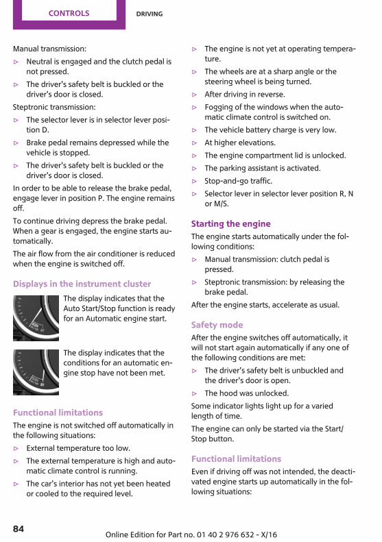
Manual transmission:▷ Neutral is engaged and the clutch pedal is
not pressed.▷ The driver's safety belt is buckled or the
driver's door is closed.Steptronic transmission:▷ The selector lever is in selector lever posi‐
tion D.▷ Brake pedal remains depressed while the
vehicle is stopped.▷ The driver's safety belt is buckled or the
driver's door is closed.In order to be able to release the brake pedal,engage lever in position P. The engine remainsoff.To continue driving depress the brake pedal.When a gear is engaged, the engine starts au‐tomatically.The air flow from the air conditioner is reducedwhen the engine is switched off.
Displays in the instrument clusterThe display indicates that theAuto Start/Stop function is readyfor an Automatic engine start.
The display indicates that theconditions for an automatic en‐gine stop have not been met.
Functional limitationsThe engine is not switched off automatically inthe following situations:▷ External temperature too low.▷ The external temperature is high and auto‐
matic climate control is running.▷ The car's interior has not yet been heated
or cooled to the required level.
▷ The engine is not yet at operating tempera‐ture.
▷ The wheels are at a sharp angle or thesteering wheel is being turned.
▷ After driving in reverse.▷ Fogging of the windows when the auto‐
matic climate control is switched on.▷ The vehicle battery charge is very low.▷ At higher elevations.▷ The engine compartment lid is unlocked.▷ The parking assistant is activated.▷ Stop-and-go traffic.▷ Selector lever in selector lever position R, N
or M/S.
Starting the engineThe engine starts automatically under the fol‐lowing conditions:▷ Manual transmission: clutch pedal is
pressed.▷ Steptronic transmission: by releasing the
brake pedal.After the engine starts, accelerate as usual.
Safety modeAfter the engine switches off automatically, itwill not start again automatically if any one ofthe following conditions are met:▷ The driver's safety belt is unbuckled and
the driver's door is open.▷ The hood was unlocked.Some indicator lights light up for a variedlength of time.The engine can only be started via the Start/Stop button.
Functional limitationsEven if driving off was not intended, the deacti‐vated engine starts up automatically in the fol‐lowing situations:
Seite 84
CONTROLS Driving
84 Online Edition for Part no. 01 40 2 976 632 - X/16
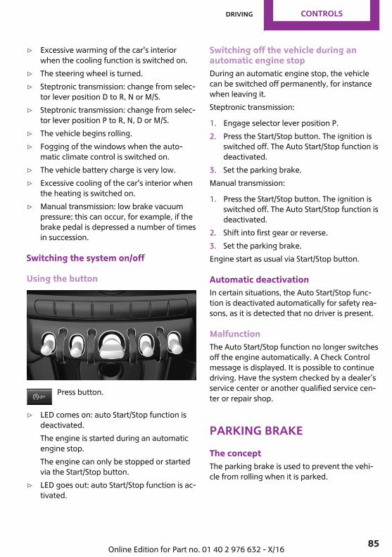
▷ Excessive warming of the car's interiorwhen the cooling function is switched on.
▷ The steering wheel is turned.▷ Steptronic transmission: change from selec‐
tor lever position D to R, N or M/S.▷ Steptronic transmission: change from selec‐
tor lever position P to R, N, D or M/S.▷ The vehicle begins rolling.▷ Fogging of the windows when the auto‐
matic climate control is switched on.▷ The vehicle battery charge is very low.▷ Excessive cooling of the car's interior when
the heating is switched on.▷ Manual transmission: low brake vacuum
pressure; this can occur, for example, if thebrake pedal is depressed a number of timesin succession.
Switching the system on/off
Using the button
Press button.
▷ LED comes on: auto Start/Stop function isdeactivated.The engine is started during an automaticengine stop.The engine can only be stopped or startedvia the Start/Stop button.
▷ LED goes out: auto Start/Stop function is ac‐tivated.
Switching off the vehicle during anautomatic engine stopDuring an automatic engine stop, the vehiclecan be switched off permanently, for instancewhen leaving it.Steptronic transmission:
1. Engage selector lever position P.2. Press the Start/Stop button. The ignition is
switched off. The Auto Start/Stop function isdeactivated.
3. Set the parking brake.Manual transmission:
1. Press the Start/Stop button. The ignition isswitched off. The Auto Start/Stop function isdeactivated.
2. Shift into first gear or reverse.3. Set the parking brake.Engine start as usual via Start/Stop button.
Automatic deactivationIn certain situations, the Auto Start/Stop func‐tion is deactivated automatically for safety rea‐sons, as it is detected that no driver is present.
MalfunctionThe Auto Start/Stop function no longer switchesoff the engine automatically. A Check Controlmessage is displayed. It is possible to continuedriving. Have the system checked by a dealer’sservice center or another qualified service cen‐ter or repair shop.
Parking brakeThe conceptThe parking brake is used to prevent the vehi‐cle from rolling when it is parked.
Seite 85
Driving CONTROLS
85Online Edition for Part no. 01 40 2 976 632 - X/16
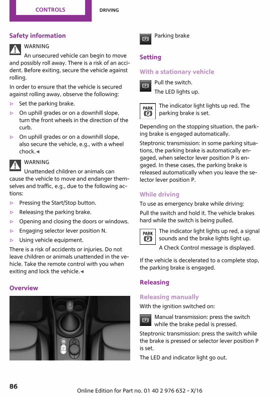
Safety informationWARNINGAn unsecured vehicle can begin to move
and possibly roll away. There is a risk of an acci‐dent. Before exiting, secure the vehicle againstrolling.In order to ensure that the vehicle is securedagainst rolling away, observe the following:▷ Set the parking brake.▷ On uphill grades or on a downhill slope,
turn the front wheels in the direction of thecurb.
▷ On uphill grades or on a downhill slope,also secure the vehicle, e.g., with a wheelchock.◀
WARNINGUnattended children or animals can
cause the vehicle to move and endanger them‐selves and traffic, e.g., due to the following ac‐tions:▷ Pressing the Start/Stop button.▷ Releasing the parking brake.▷ Opening and closing the doors or windows.▷ Engaging selector lever position N.▷ Using vehicle equipment.There is a risk of accidents or injuries. Do notleave children or animals unattended in the ve‐hicle. Take the remote control with you whenexiting and lock the vehicle.◀
Overview
Parking brake
Setting
With a stationary vehiclePull the switch.The LED lights up.
The indicator light lights up red. Theparking brake is set.
Depending on the stopping situation, the park‐ing brake is engaged automatically.Steptronic transmission: in some parking situa‐tions, the parking brake is automatically en‐gaged, when selector lever position P is en‐gaged. In these cases, the parking brake isreleased automatically when you leave the se‐lector lever position P.
While drivingTo use as emergency brake while driving:Pull the switch and hold it. The vehicle brakeshard while the switch is being pulled.
The indicator light lights up red, a signalsounds and the brake lights light up.A Check Control message is displayed.
If the vehicle is decelerated to a complete stop,the parking brake is engaged.
Releasing
Releasing manuallyWith the ignition switched on:
Manual transmission: press the switchwhile the brake pedal is pressed.
Steptronic transmission: press the switch whilethe brake is pressed or selector lever position Pis set.The LED and indicator light go out.
Seite 86
CONTROLS Driving
86 Online Edition for Part no. 01 40 2 976 632 - X/16
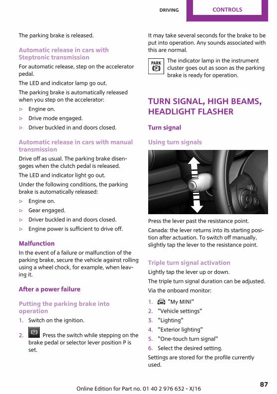
The parking brake is released.
Automatic release in cars withSteptronic transmissionFor automatic release, step on the acceleratorpedal.The LED and indicator lamp go out.The parking brake is automatically releasedwhen you step on the accelerator:▷ Engine on.▷ Drive mode engaged.▷ Driver buckled in and doors closed.
Automatic release in cars with manualtransmissionDrive off as usual. The parking brake disen‐gages when the clutch pedal is released.The LED and indicator light go out.Under the following conditions, the parkingbrake is automatically released:▷ Engine on.▷ Gear engaged.▷ Driver buckled in and doors closed.▷ Engine power is sufficient to drive off.
MalfunctionIn the event of a failure or malfunction of theparking brake, secure the vehicle against rollingusing a wheel chock, for example, when leav‐ing it.
After a power failure
Putting the parking brake intooperation1. Switch on the ignition.
2. Press the switch while stepping on thebrake pedal or selector lever position P isset.
It may take several seconds for the brake to beput into operation. Any sounds associated withthis are normal.
The indicator lamp in the instrumentcluster goes out as soon as the parkingbrake is ready for operation.
Turn signal, high beams,headlight flasherTurn signal
Using turn signals
Press the lever past the resistance point.Canada: the lever returns into its starting posi‐tion after actuation. To switch off manually,slightly tap the lever to the resistance point.
Triple turn signal activationLightly tap the lever up or down.The triple turn signal duration can be adjusted.Via the onboard monitor:
1. "My MINI"2. "Vehicle settings"3. "Lighting"4. "Exterior lighting"5. "One-touch turn signal"6. Select the desired setting.Settings are stored for the profile currentlyused.
Seite 87
Driving CONTROLS
87Online Edition for Part no. 01 40 2 976 632 - X/16

Signaling brieflyPress the lever to the resistance point and holdit there for as long as you want the turn signalto flash.
MalfunctionUnusually rapid flashing of the indicator lampindicates that a turn signal bulb has failed.
High beams, headlight flasherPush the lever forward or pull it backward.
▷ High beams on, arrow 1.▷ High beams off/headlight flasher, arrow 2.
Washer/wiper systemGeneral informationDo not use the wipers if the windshield is dry,as this may damage the wiper blades or causethem to become worn more quickly.
Safety informationWARNINGIf the wipers start moving in the folded
away state, body parts can be jammed or dam‐age may occur to parts of the vehicle. There is arisk of injury or risk of property damage. Makesure that the vehicle is switched off when thewipers are in the folded away state and thewipers are folded in when switching on.◀
NOTEIf the wipers are frozen to the windshield,
the wiper blades can be torn off and the wipermotor can overheat when switching on. Thereis a risk of property damage. Defrost the wind‐shield prior to switching the wipers on.◀
Switching on
Press the lever up until the desired position isreached.▷ Resting position of the wipers, position 0.▷ Intermittent operation or rain sensor, posi‐
tion 1.▷ Normal wiper speed, position 2.
The wipers switch to intermittent operationwhen the vehicle is stationary.
▷ Fast wiper speed, position 3.The wipers change to their normal speedwhen the vehicle comes to a standstill.
When travel is interrupted with the wiper sys‐tem switched on: when travel continues, thewipers resume at their previous speed.
Switching off and brief wipe
Seite 88
CONTROLS Driving
88 Online Edition for Part no. 01 40 2 976 632 - X/16
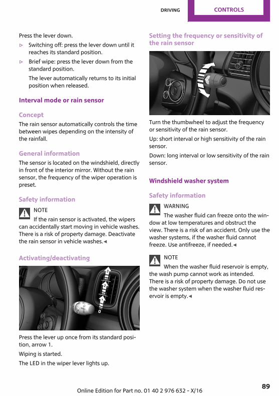
Press the lever down.▷ Switching off: press the lever down until it
reaches its standard position.▷ Brief wipe: press the lever down from the
standard position.The lever automatically returns to its initialposition when released.
Interval mode or rain sensor
ConceptThe rain sensor automatically controls the timebetween wipes depending on the intensity ofthe rainfall.
General informationThe sensor is located on the windshield, directlyin front of the interior mirror. Without the rainsensor, the frequency of the wiper operation ispreset.
Safety informationNOTEIf the rain sensor is activated, the wipers
can accidentally start moving in vehicle washes.There is a risk of property damage. Deactivatethe rain sensor in vehicle washes.◀
Activating/deactivating
Press the lever up once from its standard posi‐tion, arrow 1.Wiping is started.The LED in the wiper lever lights up.
Setting the frequency or sensitivity ofthe rain sensor
Turn the thumbwheel to adjust the frequencyor sensitivity of the rain sensor.Up: short interval or high sensitivity of the rainsensor.Down: long interval or low sensitivity of the rainsensor.
Windshield washer system
Safety informationWARNINGThe washer fluid can freeze onto the win‐
dow at low temperatures and obstruct theview. There is a risk of an accident. Only use thewasher systems, if the washer fluid cannotfreeze. Use antifreeze, if needed.◀
NOTEWhen the washer fluid reservoir is empty,
the wash pump cannot work as intended.There is a risk of property damage. Do not usethe washer system when the washer fluid res‐ervoir is empty.◀
Seite 89
Driving CONTROLS
89Online Edition for Part no. 01 40 2 976 632 - X/16
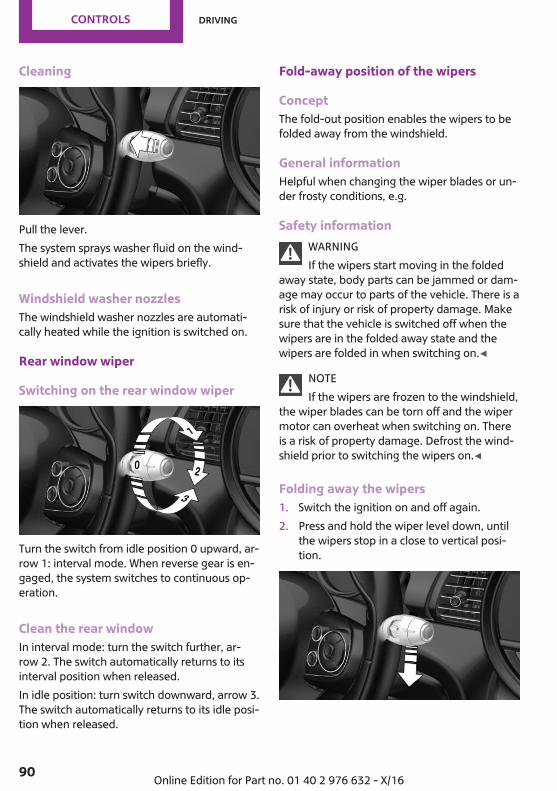
Cleaning
Pull the lever.The system sprays washer fluid on the wind‐shield and activates the wipers briefly.
Windshield washer nozzlesThe windshield washer nozzles are automati‐cally heated while the ignition is switched on.
Rear window wiper
Switching on the rear window wiper
Turn the switch from idle position 0 upward, ar‐row 1: interval mode. When reverse gear is en‐gaged, the system switches to continuous op‐eration.
Clean the rear windowIn interval mode: turn the switch further, ar‐row 2. The switch automatically returns to itsinterval position when released.In idle position: turn switch downward, arrow 3.The switch automatically returns to its idle posi‐tion when released.
Fold-away position of the wipers
ConceptThe fold-out position enables the wipers to befolded away from the windshield.
General informationHelpful when changing the wiper blades or un‐der frosty conditions, e.g.
Safety informationWARNINGIf the wipers start moving in the folded
away state, body parts can be jammed or dam‐age may occur to parts of the vehicle. There is arisk of injury or risk of property damage. Makesure that the vehicle is switched off when thewipers are in the folded away state and thewipers are folded in when switching on.◀
NOTEIf the wipers are frozen to the windshield,
the wiper blades can be torn off and the wipermotor can overheat when switching on. Thereis a risk of property damage. Defrost the wind‐shield prior to switching the wipers on.◀
Folding away the wipers1. Switch the ignition on and off again.2. Press and hold the wiper level down, until
the wipers stop in a close to vertical posi‐tion.
Seite 90
CONTROLS Driving
90 Online Edition for Part no. 01 40 2 976 632 - X/16
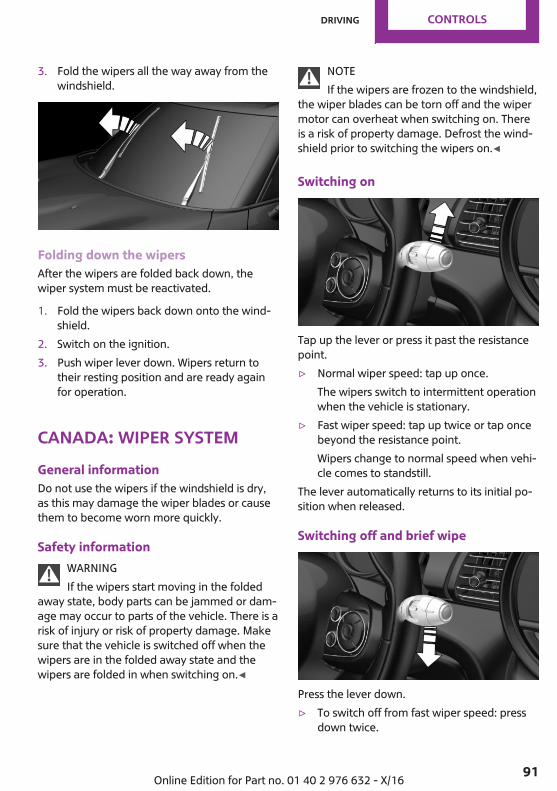
3. Fold the wipers all the way away from thewindshield.
Folding down the wipersAfter the wipers are folded back down, thewiper system must be reactivated.
1. Fold the wipers back down onto the wind‐shield.
2. Switch on the ignition.3. Push wiper lever down. Wipers return to
their resting position and are ready againfor operation.
Canada: wiper systemGeneral informationDo not use the wipers if the windshield is dry,as this may damage the wiper blades or causethem to become worn more quickly.
Safety informationWARNINGIf the wipers start moving in the folded
away state, body parts can be jammed or dam‐age may occur to parts of the vehicle. There is arisk of injury or risk of property damage. Makesure that the vehicle is switched off when thewipers are in the folded away state and thewipers are folded in when switching on.◀
NOTEIf the wipers are frozen to the windshield,
the wiper blades can be torn off and the wipermotor can overheat when switching on. Thereis a risk of property damage. Defrost the wind‐shield prior to switching the wipers on.◀
Switching on
Tap up the lever or press it past the resistancepoint.▷ Normal wiper speed: tap up once.
The wipers switch to intermittent operationwhen the vehicle is stationary.
▷ Fast wiper speed: tap up twice or tap oncebeyond the resistance point.Wipers change to normal speed when vehi‐cle comes to standstill.
The lever automatically returns to its initial po‐sition when released.
Switching off and brief wipe
Press the lever down.▷ To switch off from fast wiper speed: press
down twice.
Seite 91
Driving CONTROLS
91Online Edition for Part no. 01 40 2 976 632 - X/16
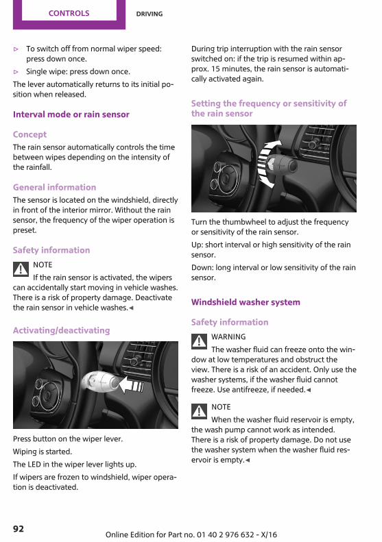
▷ To switch off from normal wiper speed:press down once.
▷ Single wipe: press down once.The lever automatically returns to its initial po‐sition when released.
Interval mode or rain sensor
ConceptThe rain sensor automatically controls the timebetween wipes depending on the intensity ofthe rainfall.
General informationThe sensor is located on the windshield, directlyin front of the interior mirror. Without the rainsensor, the frequency of the wiper operation ispreset.
Safety informationNOTEIf the rain sensor is activated, the wipers
can accidentally start moving in vehicle washes.There is a risk of property damage. Deactivatethe rain sensor in vehicle washes.◀
Activating/deactivating
Press button on the wiper lever.Wiping is started.The LED in the wiper lever lights up.If wipers are frozen to windshield, wiper opera‐tion is deactivated.
During trip interruption with the rain sensorswitched on: if the trip is resumed within ap‐prox. 15 minutes, the rain sensor is automati‐cally activated again.
Setting the frequency or sensitivity ofthe rain sensor
Turn the thumbwheel to adjust the frequencyor sensitivity of the rain sensor.Up: short interval or high sensitivity of the rainsensor.Down: long interval or low sensitivity of the rainsensor.
Windshield washer system
Safety informationWARNINGThe washer fluid can freeze onto the win‐
dow at low temperatures and obstruct theview. There is a risk of an accident. Only use thewasher systems, if the washer fluid cannotfreeze. Use antifreeze, if needed.◀
NOTEWhen the washer fluid reservoir is empty,
the wash pump cannot work as intended.There is a risk of property damage. Do not usethe washer system when the washer fluid res‐ervoir is empty.◀
Seite 92
CONTROLS Driving
92 Online Edition for Part no. 01 40 2 976 632 - X/16

Cleaning
Pull the lever.The system sprays washer fluid on the wind‐shield and activates the wipers briefly.
Windshield washer nozzlesThe windshield washer nozzles are automati‐cally heated while the ignition is switched on.
Rear window wiper
Switching on the rear window wiper
Turn the switch from idle position 0 upward, ar‐row 1: interval mode. When reverse gear is en‐gaged, the system switches to continuous op‐eration.
Clean the rear windowIn interval mode: turn the switch further, ar‐row 2. The switch automatically returns to itsinterval position when released.In idle position: turn switch downward, arrow 3.The switch automatically returns to its idle posi‐tion when released.
Fold-away position of the wipers
ConceptThe fold-out position enables the wipers to befolded away from the windshield.
General informationHelpful when changing the wiper blades or un‐der frosty conditions, e.g.
Safety informationWARNINGIf the wipers start moving in the folded
away state, body parts can be jammed or dam‐age may occur to parts of the vehicle. There is arisk of injury or risk of property damage. Makesure that the vehicle is switched off when thewipers are in the folded away state and thewipers are folded in when switching on.◀
NOTEIf the wipers are frozen to the windshield,
the wiper blades can be torn off and the wipermotor can overheat when switching on. Thereis a risk of property damage. Defrost the wind‐shield prior to switching the wipers on.◀
Folding away the wipers1. Switch the ignition on and off again.2. Press the wiper lever up beyond the point
of resistance and hold it for approx. 3 sec‐onds, until the wipers remain in a nearlyvertical position
Seite 93
Driving CONTROLS
93Online Edition for Part no. 01 40 2 976 632 - X/16
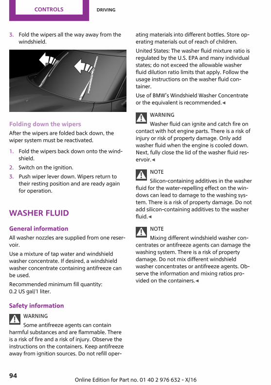
3. Fold the wipers all the way away from thewindshield.
Folding down the wipersAfter the wipers are folded back down, thewiper system must be reactivated.
1. Fold the wipers back down onto the wind‐shield.
2. Switch on the ignition.3. Push wiper lever down. Wipers return to
their resting position and are ready againfor operation.
Washer fluidGeneral informationAll washer nozzles are supplied from one reser‐voir.Use a mixture of tap water and windshieldwasher concentrate. If desired, a windshieldwasher concentrate containing antifreeze canbe used.Recommended minimum fill quantity:0.2 US gal/1 liter.
Safety informationWARNINGSome antifreeze agents can contain
harmful substances and are flammable. Thereis a risk of fire and a risk of injury. Observe theinstructions on the containers. Keep antifreezeaway from ignition sources. Do not refill oper‐
ating materials into different bottles. Store op‐erating materials out of reach of children.United States: The washer fluid mixture ratio isregulated by the U.S. EPA and many individualstates; do not exceed the allowable washerfluid dilution ratio limits that apply. Follow theusage instructions on the washer fluid con‐tainer.Use of BMW’s Windshield Washer Concentrateor the equivalent is recommended.◀
WARNINGWasher fluid can ignite and catch fire on
contact with hot engine parts. There is a risk ofinjury or risk of property damage. Only addwasher fluid when the engine is cooled down.Next, fully close the lid of the washer fluid res‐ervoir.◀
NOTESilicon-containing additives in the washer
fluid for the water-repelling effect on the win‐dows can lead to damage to the washing sys‐tem. There is a risk of property damage. Do notadd silicon-containing additives to the washerfluid.◀
NOTEMixing different windshield washer con‐
centrates or antifreeze agents can damage thewashing system. There is a risk of propertydamage. Do not mix different windshieldwasher concentrates or antifreeze agents. Ob‐serve the information and mixing ratios pro‐vided on the containers.◀
Seite 94
CONTROLS Driving
94 Online Edition for Part no. 01 40 2 976 632 - X/16

Overview
The washer fluid reservoir is located in the en‐gine compartment.
MalfunctionThe use of undiluted windshield washer con‐centrate or alcohol-based antifreeze can leadto incorrect readings at temperatures below+5 ℉/-15 ℃.
Manual transmissionSafety information
WARNINGAn unsecured vehicle can begin to move
and possibly roll away. There is a risk of an acci‐dent. Before exiting, secure the vehicle againstrolling.In order to ensure that the vehicle is securedagainst rolling away, observe the following:▷ Set the parking brake.▷ On uphill grades or on a downhill slope,
turn the front wheels in the direction of thecurb.
▷ On uphill grades or on a downhill slope,also secure the vehicle, e.g., with a wheelchock.◀
NOTEWhen shifting to a lower gear, excessive
speeds can damage the engine. There is a riskof property damage. When shifting into 5th or6th gear, press the gearshift lever to the right.◀
Shifting
General informationThe engine speed during shifting is adjustedautomatically for harmonious and dynamicgear shifting.
Reverse gearSelect only when the vehicle is stationary.To overcome the resistance push the gearshiftlever dynamically to the left and engage re‐verse gear with a forward shifting movement.
Steptronic transmissionConceptThe Steptronic transmission combines the func‐tions of an automatic transmission with thepossibility of manual shifting, if needed.
Safety informationWARNINGAn unsecured vehicle can begin to move
and possibly roll away. There is a risk of an acci‐dent. Before exiting, secure the vehicle againstrolling.In order to ensure that the vehicle is securedagainst rolling away, observe the following:▷ Set the parking brake.▷ On uphill grades or on a downhill slope,
turn the front wheels in the direction of thecurb.
▷ On uphill grades or on a downhill slope,also secure the vehicle, e.g., with a wheelchock.◀
Selector lever positions
Drive mode DSelector lever position for normal vehicle oper‐ation. All gears for forward travel are activatedautomatically.
Seite 95
Driving CONTROLS
95Online Edition for Part no. 01 40 2 976 632 - X/16
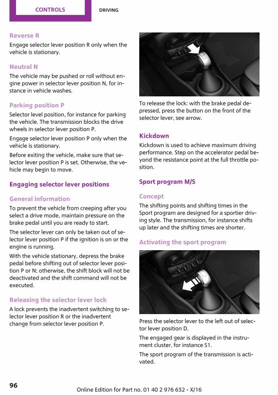
Reverse REngage selector lever position R only when thevehicle is stationary.
Neutral NThe vehicle may be pushed or roll without en‐gine power in selector lever position N, for in‐stance in vehicle washes.
Parking position PSelector level position, for instance for parkingthe vehicle. The transmission blocks the drivewheels in selector lever position P.Engage selector lever position P only when thevehicle is stationary.Before exiting the vehicle, make sure that se‐lector lever position P is set. Otherwise, the ve‐hicle may begin to move.
Engaging selector lever positions
General informationTo prevent the vehicle from creeping after youselect a drive mode, maintain pressure on thebrake pedal until you are ready to start.The selector lever can only be taken out of se‐lector lever position P if the ignition is on or theengine is running.With the vehicle stationary, depress the brakepedal before shifting out of selector lever posi‐tion P or N; otherwise, the shift block will not bedeactivated and the shift command will not beexecuted.
Releasing the selector lever lockA lock prevents the inadvertent switching to se‐lector lever position R or the inadvertentchange from selector lever position P.
To release the lock: with the brake pedal de‐pressed, press the button on the front of theselector lever, see arrow.
KickdownKickdown is used to achieve maximum drivingperformance. Step on the accelerator pedal be‐yond the resistance point at the full throttle po‐sition.
Sport program M/S
ConceptThe shifting points and shifting times in theSport program are designed for a sportier driv‐ing style. The transmission, for instance shiftsup later and the shifting times are shorter.
Activating the sport program
Press the selector lever to the left out of selec‐tor lever position D.The engaged gear is displayed in the instru‐ment cluster, for instance S1.The sport program of the transmission is acti‐vated.
Seite 96
CONTROLS Driving
96 Online Edition for Part no. 01 40 2 976 632 - X/16
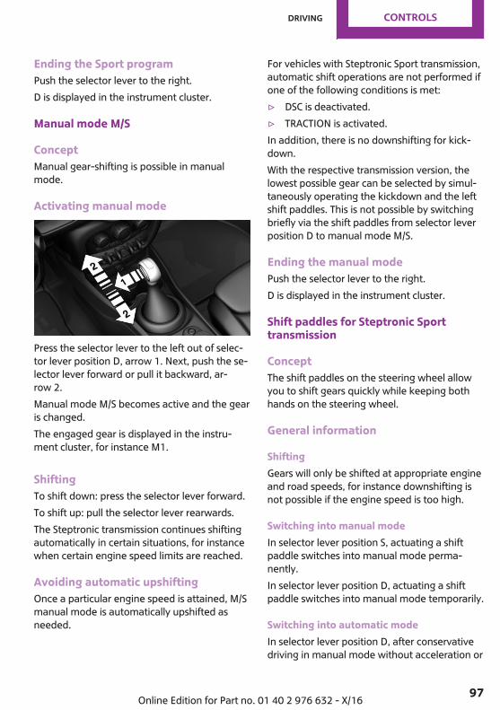
Ending the Sport programPush the selector lever to the right.D is displayed in the instrument cluster.
Manual mode M/S
ConceptManual gear-shifting is possible in manualmode.
Activating manual mode
Press the selector lever to the left out of selec‐tor lever position D, arrow 1. Next, push the se‐lector lever forward or pull it backward, ar‐row 2.Manual mode M/S becomes active and the gearis changed.The engaged gear is displayed in the instru‐ment cluster, for instance M1.
ShiftingTo shift down: press the selector lever forward.To shift up: pull the selector lever rearwards.The Steptronic transmission continues shiftingautomatically in certain situations, for instancewhen certain engine speed limits are reached.
Avoiding automatic upshiftingOnce a particular engine speed is attained, M/Smanual mode is automatically upshifted asneeded.
For vehicles with Steptronic Sport transmission,automatic shift operations are not performed ifone of the following conditions is met:▷ DSC is deactivated.▷ TRACTION is activated.In addition, there is no downshifting for kick‐down.With the respective transmission version, thelowest possible gear can be selected by simul‐taneously operating the kickdown and the leftshift paddles. This is not possible by switchingbriefly via the shift paddles from selector leverposition D to manual mode M/S.
Ending the manual modePush the selector lever to the right.D is displayed in the instrument cluster.
Shift paddles for Steptronic Sporttransmission
ConceptThe shift paddles on the steering wheel allowyou to shift gears quickly while keeping bothhands on the steering wheel.
General information
ShiftingGears will only be shifted at appropriate engineand road speeds, for instance downshifting isnot possible if the engine speed is too high.
Switching into manual modeIn selector lever position S, actuating a shiftpaddle switches into manual mode perma‐nently.In selector lever position D, actuating a shiftpaddle switches into manual mode temporarily.
Switching into automatic modeIn selector lever position D, after conservativedriving in manual mode without acceleration or
Seite 97
Driving CONTROLS
97Online Edition for Part no. 01 40 2 976 632 - X/16
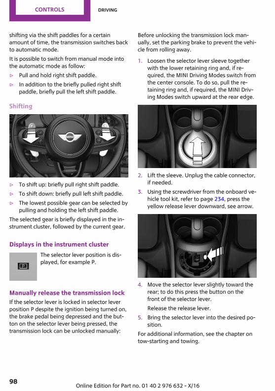
shifting via the shift paddles for a certainamount of time, the transmission switches backto automatic mode.It is possible to switch from manual mode intothe automatic mode as follow:▷ Pull and hold right shift paddle.▷ In addition to the briefly pulled right shift
paddle, briefly pull the left shift paddle.
Shifting
▷ To shift up: briefly pull right shift paddle.▷ To shift down: briefly pull left shift paddle.▷ The lowest possible gear can be selected by
pulling and holding the left shift paddle.The selected gear is briefly displayed in the in‐strument cluster, followed by the current gear.
Displays in the instrument clusterThe selector lever position is dis‐played, for example P.
Manually release the transmission lockIf the selector lever is locked in selector leverposition P despite the ignition being turned on,the brake pedal being depressed and the but‐ton on the selector lever being pressed, thetransmission lock can be unlocked manually:
Before unlocking the transmission lock man‐ually, set the parking brake to prevent the vehi‐cle from rolling away.
1. Loosen the selector lever sleeve togetherwith the lower retaining ring and, if re‐quired, the MINI Driving Modes switch fromthe center console. To do so, pull the re‐taining ring and, if required, the MINI Driv‐ing Modes switch upward at the rear edge.
2. Lift the sleeve. Unplug the cable connector,if needed.
3. Using the screwdriver from the onboard ve‐hicle tool kit, refer to page 234, press theyellow release lever downward, see arrow.
4. Move the selector lever slightly toward therear; to do this press the button on thefront of the selector lever.Release the release lever.
5. Bring the selector lever into the desired po‐sition.
For additional information, see the chapter ontow-starting and towing.
Seite 98
CONTROLS Driving
98 Online Edition for Part no. 01 40 2 976 632 - X/16
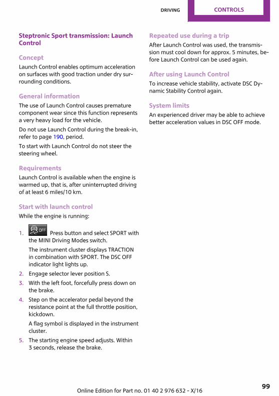
Steptronic Sport transmission: LaunchControl
ConceptLaunch Control enables optimum accelerationon surfaces with good traction under dry sur‐rounding conditions.
General informationThe use of Launch Control causes prematurecomponent wear since this function representsa very heavy load for the vehicle.Do not use Launch Control during the break-in,refer to page 190, period.To start with Launch Control do not steer thesteering wheel.
RequirementsLaunch Control is available when the engine iswarmed up, that is, after uninterrupted drivingof at least 6 miles/10 km.
Start with launch controlWhile the engine is running:
1. Press button and select SPORT withthe MINI Driving Modes switch.The instrument cluster displays TRACTIONin combination with SPORT. The DSC OFFindicator light lights up.
2. Engage selector lever position S.3. With the left foot, forcefully press down on
the brake.4. Step on the accelerator pedal beyond the
resistance point at the full throttle position,kickdown.A flag symbol is displayed in the instrumentcluster.
5. The starting engine speed adjusts. Within3 seconds, release the brake.
Repeated use during a tripAfter Launch Control was used, the transmis‐sion must cool down for approx. 5 minutes, be‐fore Launch Control can be used again.
After using Launch ControlTo increase vehicle stability, activate DSC Dy‐namic Stability Control again.
System limitsAn experienced driver may be able to achievebetter acceleration values in DSC OFF mode.
Seite 99
Driving CONTROLS
99Online Edition for Part no. 01 40 2 976 632 - X/16
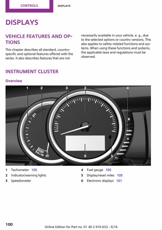
DisplaysVehicle features and op‐tionsThis chapter describes all standard, country-specific and optional features offered with theseries. It also describes features that are not
necessarily available in your vehicle, e. g., dueto the selected options or country versions. Thisalso applies to safety-related functions and sys‐tems. When using these functions and systems,the applicable laws and regulations must beobserved.
Instrument clusterOverview
1 Tachometer 1052 Indicator/warning lights3 Speedometer
4 Fuel gauge 1055 Display/reset miles 1056 Electronic displays 101
Seite 100
CONTROLS Displays
100 Online Edition for Part no. 01 40 2 976 632 - X/16

Electronic displays
1 Driver assistance systemsMessages, for instance Check ControlTime 105External temperature 105Selection lists 109
Total miles/trip odometer 105Onboard computer 109
2 Selector lever position 95Gear shift indicator 107
3 MINI Driving Modes switch status 143
Check ControlConceptThe Check Control system monitors functions inthe vehicle and notifies you of malfunctions inthe monitored systems.
General informationA Check Control message is displayed as a com‐bination of indicator or warning lights and SMStext messages in the instrument cluster and inthe Head-up Display.In addition, an acoustic signal may be outputand a SMS text message may appear on theControl Display.
Indicator/warning lights
General informationThe indicator and warning lights can light up ina variety of combinations and colors.Several of the lights are checked for properfunctioning and light up temporarily when theengine is started or the ignition is switched on.
Red lights
Safety belt reminderIndicator lamp flashes or illuminates:safety belt on the driver or front pas‐senger side is not buckled. The safety
belt reminder can also be activated if objectsare placed on the front passenger seat.
Seite 101
Displays CONTROLS
101Online Edition for Part no. 01 40 2 976 632 - X/16

Make sure that the safety belts are positionedcorrectly.
Airbag systemAirbag system and belt tensioner arenot working.Have the vehicle checked immediately
by a dealer’s service center or another qualifiedservice center or repair shop.
Parking brakeThe parking brake is set.Release the parking brake, refer topage 86.
Brake systemBraking system impaired. Continue todrive moderately.Have the vehicle checked immediatelyby a dealer’s service center or anotherqualified service center or repair shop.
Approach control warningIndicator light illuminates: advancewarning is issued, for example whenthere is the impending danger of a colli‐
sion or the distance to the vehicle ahead is toosmall.Increase distance.Indicator light flashes: acute warning of the im‐minent danger of a collision when the vehicleapproaches another vehicle at a relatively highdifferential speed.Intervention by braking or make an evasivemaneuver.
Pedestrian warningIf a collision with a person detected inthis way is imminent, the symbol lightsup and a signal sounds.
Orange lights
Active Cruise ControlThe number bars shows the selecteddistance from the vehicle driving ahead.Camera-based cruise control, refer to
page 145.
Vehicle detection, Active Cruise ControlIndicator lamp illuminates: a vehicle hasbeen detected ahead of you.Indicator lamp flashes: the conditions
are not adequate for the system to work.The system was deactivated but applies thebrakes until you actively resume control bypressing on the brake pedal or acceleratorpedal.
Yellow lights
Anti-lock Braking System ABSBraking force boost may not be work‐ing. Avoid abrupt braking. Take the lon‐ger braking distance into account.Have the system immediately checkedby a dealer’s service center or another
qualified service center or repair shop.
DSC Dynamic Stability ControlThe indicator light flashes: DSC controlsthe drive and braking forces. The vehi‐cle is stabilized. Reduce speed and
adapt driving style to the driving circumstances.The indicator light lights up: DSC has malfunc‐tioned.Have the system checked by a dealer’s servicecenter or another qualified service center or re‐pair shop.DSC Dynamic Stability Control, refer topage 141.
Seite 102
CONTROLS Displays
102 Online Edition for Part no. 01 40 2 976 632 - X/16
DSC Dynamic Stability Control is deactivatedor DTC Dynamic Traction Control is activated
DSC Dynamic Stability Control is deacti‐vated or DTC Dynamic Traction Controlis activated.
DSC Dynamic Stability Control, refer topage 141, and DTC Dynamic Traction Control,refer to page 142.
Flat Tire Monitor FTMThe Flat Tire Monitor signals a loss oftire inflation pressure in a tire.Reduce your speed and stop cautiously.
Avoid sudden braking and steering maneuvers.Flat Tire Monitor, refer to page 130.
Tire Pressure Monitor TPMThe indicator light illuminates.The Tire Pressure Monitor reports a lowtire inflation pressure or a flat tire.
Observe the information in the Check Controlmessage.The indicator light flashes and then illuminatescontinuously.No flat tire or loss of tire inflation pressure canbe detected.▷ Interference caused by systems or devices
with the same radio frequency: after leav‐ing the area of the interference, the systemautomatically becomes active again.
▷ TPM was unable to complete the reset. Re‐set the system again.
▷ A wheel without TPM electronics ismounted: have it checked by a dealer’sservice center or another qualified servicecenter or repair shop as needed.
▷ Malfunction: have the system checked by adealer’s service center or another qualifiedservice center or repair shop.
Tire Pressure Monitor, refer to page 126.
Steering systemSteering system in some cases notworking.Have the steering system checked by a
dealer’s service center or another qualifiedservice center or repair shop.
Emissions▷ The warning light lights up:
Emissions are deteriorating. Havethe vehicle checked as soon as pos‐sible.
▷ The warning light flashes under certain cir‐cumstances:This indicates that there is excessive misfir‐ing in the engine.Reduce the vehicle speed and have the sys‐tem checked immediately; otherwise, seri‐ous engine misfiring within a brief periodcan seriously damage emission controlcomponents, in particular the catalytic con‐verter.
Socket for Onboard Diagnosis, refer topage 233.
Green lights
Turn signalTurn signal switched on.Unusually rapid flashing of the indicatorlight indicates that a turn signal bulb
has failed.Turn signal, refer to page 87.
Parking lights, headlightParking lights or headlights are acti‐vated.Parking lights/low beams, headlight
control, refer to page 118.
Seite 103
Displays CONTROLS
103Online Edition for Part no. 01 40 2 976 632 - X/16
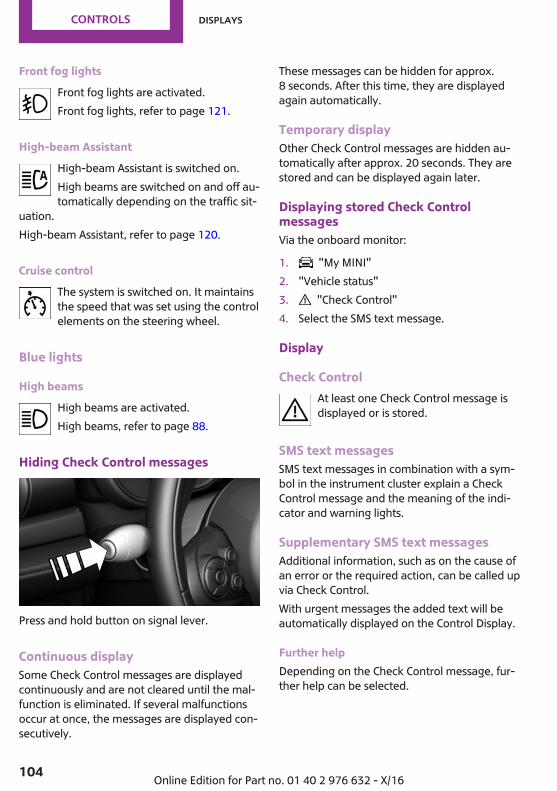
Front fog lightsFront fog lights are activated.Front fog lights, refer to page 121.
High-beam AssistantHigh-beam Assistant is switched on.High beams are switched on and off au‐tomatically depending on the traffic sit‐
uation.High-beam Assistant, refer to page 120.
Cruise controlThe system is switched on. It maintainsthe speed that was set using the controlelements on the steering wheel.
Blue lights
High beamsHigh beams are activated.High beams, refer to page 88.
Hiding Check Control messages
Press and hold button on signal lever.
Continuous displaySome Check Control messages are displayedcontinuously and are not cleared until the mal‐function is eliminated. If several malfunctionsoccur at once, the messages are displayed con‐secutively.
These messages can be hidden for approx.8 seconds. After this time, they are displayedagain automatically.
Temporary displayOther Check Control messages are hidden au‐tomatically after approx. 20 seconds. They arestored and can be displayed again later.
Displaying stored Check ControlmessagesVia the onboard monitor:
1. "My MINI"2. "Vehicle status"3. "Check Control"4. Select the SMS text message.
Display
Check ControlAt least one Check Control message isdisplayed or is stored.
SMS text messagesSMS text messages in combination with a sym‐bol in the instrument cluster explain a CheckControl message and the meaning of the indi‐cator and warning lights.
Supplementary SMS text messagesAdditional information, such as on the cause ofan error or the required action, can be called upvia Check Control.With urgent messages the added text will beautomatically displayed on the Control Display.
Further helpDepending on the Check Control message, fur‐ther help can be selected.
Seite 104
CONTROLS Displays
104 Online Edition for Part no. 01 40 2 976 632 - X/16
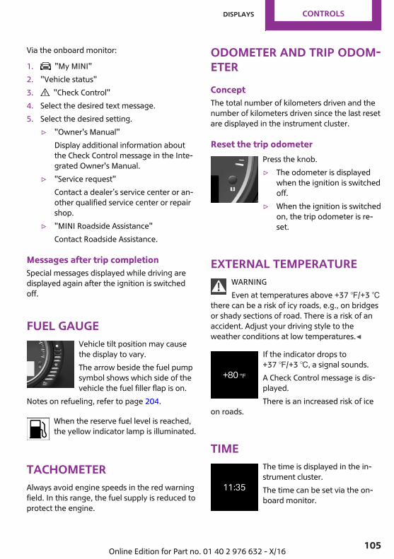
Via the onboard monitor:
1. "My MINI"2. "Vehicle status"3. "Check Control"4. Select the desired text message.5. Select the desired setting.
▷ "Owner's Manual"Display additional information aboutthe Check Control message in the Inte‐grated Owner's Manual.
▷ "Service request"Contact a dealer’s service center or an‐other qualified service center or repairshop.
▷ "MINI Roadside Assistance"Contact Roadside Assistance.
Messages after trip completionSpecial messages displayed while driving aredisplayed again after the ignition is switchedoff.
Fuel gaugeVehicle tilt position may causethe display to vary.The arrow beside the fuel pumpsymbol shows which side of thevehicle the fuel filler flap is on.
Notes on refueling, refer to page 204.
When the reserve fuel level is reached,the yellow indicator lamp is illuminated.
TachometerAlways avoid engine speeds in the red warningfield. In this range, the fuel supply is reduced toprotect the engine.
Odometer and trip odom‐eterConceptThe total number of kilometers driven and thenumber of kilometers driven since the last resetare displayed in the instrument cluster.
Reset the trip odometerPress the knob.▷ The odometer is displayed
when the ignition is switchedoff.
▷ When the ignition is switchedon, the trip odometer is re‐set.
External temperatureWARNINGEven at temperatures above +37 ℉/+3 ℃
there can be a risk of icy roads, e.g., on bridgesor shady sections of road. There is a risk of anaccident. Adjust your driving style to theweather conditions at low temperatures.◀
If the indicator drops to+37 ℉/+3 ℃, a signal sounds.A Check Control message is dis‐played.There is an increased risk of ice
on roads.
TimeThe time is displayed in the in‐strument cluster.The time can be set via the on‐board monitor.
Seite 105
Displays CONTROLS
105Online Edition for Part no. 01 40 2 976 632 - X/16
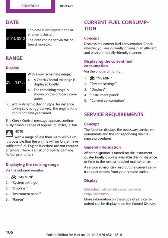
DateThe date is displayed in the in‐strument cluster.The date can be set via the on‐board monitor.
RangeDisplay
With a low remaining range:▷ A Check Control message is
displayed briefly.▷ The remaining range is
shown on the onboard com‐puter.
▷ With a dynamic driving style, for instancetaking curves aggressively, the engine func‐tion is not always ensured.
The Check Control message appears continu‐ously below a range of approx. 30 miles/50 km.
NOTEWith a range of less than 30 miles/50 km
it is possible that the engine will no longer havesufficient fuel. Engine functions are not ensuredanymore. There is a risk of property damage.Refuel promptly.◀
Displaying the cruising rangeVia the onboard monitor:
1. "My MINI"2. "System settings"3. "Displays"4. "Instrument panel"5. "Range"
Current fuel consump‐tionConceptDisplays the current fuel consumption. Checkwhether you are currently driving in an efficientand environmentally-friendly manner.
Displaying the current fuelconsumptionVia the onboard monitor:
1. "My MINI"2. "System settings"3. "Displays"4. "Instrument panel"5. "Current consumption"
Service requirementsConceptThe function displays the necessary service re‐quirements and the corresponding mainte‐nance procedures.
General informationAfter the ignition is turned on the instrumentcluster briefly displays available driving distanceor time to the next scheduled maintenance.A service advisor can read out the current serv‐ice requirements from your remote control.
Display
Detailed information on servicerequirementsMore information on the scope of service re‐quired can be displayed on the Control Display.
Seite 106
CONTROLS Displays
106 Online Edition for Part no. 01 40 2 976 632 - X/16
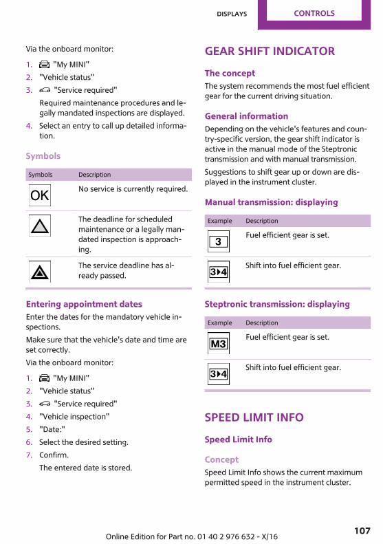
Via the onboard monitor:
1. "My MINI"2. "Vehicle status"3. "Service required"
Required maintenance procedures and le‐gally mandated inspections are displayed.
4. Select an entry to call up detailed informa‐tion.
Symbols
Symbols Description
No service is currently required.
The deadline for scheduledmaintenance or a legally man‐dated inspection is approach‐ing.
The service deadline has al‐ready passed.
Entering appointment datesEnter the dates for the mandatory vehicle in‐spections.Make sure that the vehicle's date and time areset correctly.Via the onboard monitor:
1. "My MINI"2. "Vehicle status"3. "Service required"4. "Vehicle inspection"5. "Date:"6. Select the desired setting.7. Confirm.
The entered date is stored.
Gear shift indicatorThe conceptThe system recommends the most fuel efficientgear for the current driving situation.
General informationDepending on the vehicle's features and coun‐try-specific version, the gear shift indicator isactive in the manual mode of the Steptronictransmission and with manual transmission.Suggestions to shift gear up or down are dis‐played in the instrument cluster.
Manual transmission: displaying
Example Description
Fuel efficient gear is set.
Shift into fuel efficient gear.
Steptronic transmission: displaying
Example Description
Fuel efficient gear is set.
Shift into fuel efficient gear.
Speed Limit InfoSpeed Limit Info
ConceptSpeed Limit Info shows the current maximumpermitted speed in the instrument cluster.
Seite 107
Displays CONTROLS
107Online Edition for Part no. 01 40 2 976 632 - X/16

General informationThe camera at the base of the interior mirrordetects traffic signs at the edge of the road aswell as variable overhead sign posts. Trafficsigns with extra symbols for wet road condi‐tions, etc., are also detected and comparedwith the vehicle's onboard data, such as fromthe rain sensor, and will be displayed depend‐ing on the situation.With the navigation system, the system takesinto account the information stored in the navi‐gation data and also displays speed limits pres‐ent on routes without signs.Without a navigation system, the system is sub‐ject to limitations imposed by technology. Traf‐fic signs with speed limitations are detectedand displayed only. Speed limitations due toentering or exiting towns, highway signs, etc.are not displayed. Speed limits with extra textcharacters are always displayed.
Safety informationWARNINGThe system does not release from the
personal responsibility to correctly assess visi‐bility and traffic situation. There is a risk of anaccident. Adjust the driving style to the trafficconditions. Watch traffic closely and actively in‐tervene in the respective situations.◀
Overview
Camera
The camera is installed near the interior mirror.
Keep the windshield in the area behind the in‐terior mirror clean and clear.
DisplaySpeed limit detection is displayed via the on‐board computer.
Press button on the turn signal lever severaltimes, if needed.
Speed limit detection is displayed on the CID(central information display) in the instrumentcluster.
Speed Limit InfoThe last speed limit detected.Without a navigation system thetraffic signals are grayed out af‐ter curves or longer stretches ofroadway.
With navigation system: speedlimit detection is not available.
Without navigation system: nospeed limit or cancellation is de‐tected.
Speed Limit Info can also be displayed in theHead-up Display.
Seite 108
CONTROLS Displays
108 Online Edition for Part no. 01 40 2 976 632 - X/16
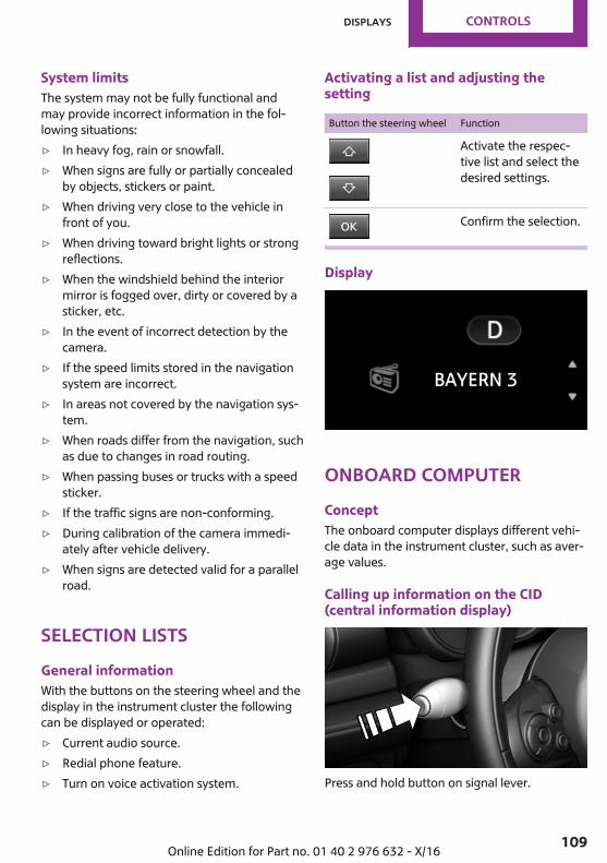
System limitsThe system may not be fully functional andmay provide incorrect information in the fol‐lowing situations:▷ In heavy fog, rain or snowfall.▷ When signs are fully or partially concealed
by objects, stickers or paint.▷ When driving very close to the vehicle in
front of you.▷ When driving toward bright lights or strong
reflections.▷ When the windshield behind the interior
mirror is fogged over, dirty or covered by asticker, etc.
▷ In the event of incorrect detection by thecamera.
▷ If the speed limits stored in the navigationsystem are incorrect.
▷ In areas not covered by the navigation sys‐tem.
▷ When roads differ from the navigation, suchas due to changes in road routing.
▷ When passing buses or trucks with a speedsticker.
▷ If the traffic signs are non-conforming.▷ During calibration of the camera immedi‐
ately after vehicle delivery.▷ When signs are detected valid for a parallel
road.
Selection listsGeneral informationWith the buttons on the steering wheel and thedisplay in the instrument cluster the followingcan be displayed or operated:▷ Current audio source.▷ Redial phone feature.▷ Turn on voice activation system.
Activating a list and adjusting thesetting
Button the steering wheel Function
Activate the respec‐tive list and select thedesired settings.
Confirm the selection.
Display
Onboard computerConceptThe onboard computer displays different vehi‐cle data in the instrument cluster, such as aver‐age values.
Calling up information on the CID(central information display)
Press and hold button on signal lever.
Seite 109
Displays CONTROLS
109Online Edition for Part no. 01 40 2 976 632 - X/16
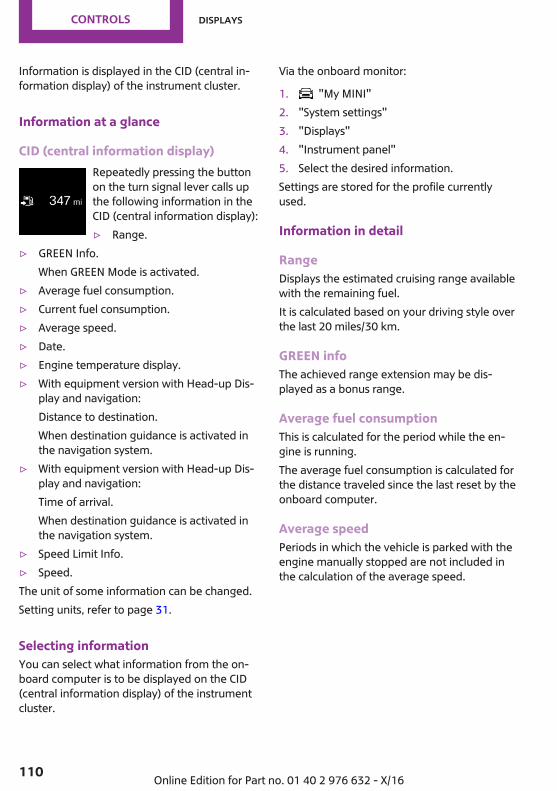
Information is displayed in the CID (central in‐formation display) of the instrument cluster.
Information at a glance
CID (central information display)Repeatedly pressing the buttonon the turn signal lever calls upthe following information in theCID (central information display):▷ Range.
▷ GREEN Info.When GREEN Mode is activated.
▷ Average fuel consumption.▷ Current fuel consumption.▷ Average speed.▷ Date.▷ Engine temperature display.▷ With equipment version with Head-up Dis‐
play and navigation:Distance to destination.When destination guidance is activated inthe navigation system.
▷ With equipment version with Head-up Dis‐play and navigation:Time of arrival.When destination guidance is activated inthe navigation system.
▷ Speed Limit Info.▷ Speed.The unit of some information can be changed.Setting units, refer to page 31.
Selecting informationYou can select what information from the on‐board computer is to be displayed on the CID(central information display) of the instrumentcluster.
Via the onboard monitor:
1. "My MINI"2. "System settings"3. "Displays"4. "Instrument panel"5. Select the desired information.Settings are stored for the profile currentlyused.
Information in detail
RangeDisplays the estimated cruising range availablewith the remaining fuel.It is calculated based on your driving style overthe last 20 miles/30 km.
GREEN infoThe achieved range extension may be dis‐played as a bonus range.
Average fuel consumptionThis is calculated for the period while the en‐gine is running.The average fuel consumption is calculated forthe distance traveled since the last reset by theonboard computer.
Average speedPeriods in which the vehicle is parked with theengine manually stopped are not included inthe calculation of the average speed.
Seite 110
CONTROLS Displays
110 Online Edition for Part no. 01 40 2 976 632 - X/16
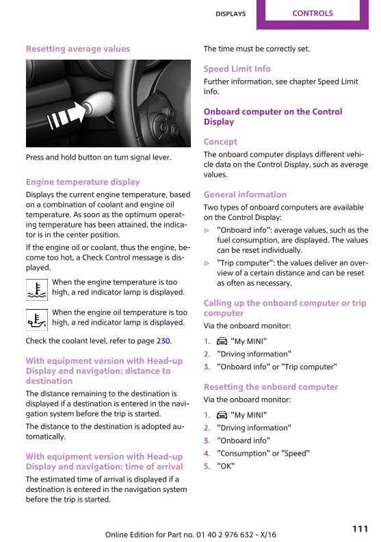
Resetting average values
Press and hold button on turn signal lever.
Engine temperature displayDisplays the current engine temperature, basedon a combination of coolant and engine oiltemperature. As soon as the optimum operat‐ing temperature has been attained, the indica‐tor is in the center position.If the engine oil or coolant, thus the engine, be‐come too hot, a Check Control message is dis‐played.
When the engine temperature is toohigh, a red indicator lamp is displayed.
When the engine oil temperature is toohigh, a red indicator lamp is displayed.
Check the coolant level, refer to page 230.
With equipment version with Head-upDisplay and navigation: distance todestinationThe distance remaining to the destination isdisplayed if a destination is entered in the navi‐gation system before the trip is started.The distance to the destination is adopted au‐tomatically.
With equipment version with Head-upDisplay and navigation: time of arrivalThe estimated time of arrival is displayed if adestination is entered in the navigation systembefore the trip is started.
The time must be correctly set.
Speed Limit InfoFurther information, see chapter Speed LimitInfo.
Onboard computer on the ControlDisplay
ConceptThe onboard computer displays different vehi‐cle data on the Control Display, such as averagevalues.
General informationTwo types of onboard computers are availableon the Control Display:▷ "Onboard info": average values, such as the
fuel consumption, are displayed. The valuescan be reset individually.
▷ "Trip computer": the values deliver an over‐view of a certain distance and can be resetas often as necessary.
Calling up the onboard computer or tripcomputerVia the onboard monitor:
1. "My MINI"2. "Driving information"3. "Onboard info" or "Trip computer"
Resetting the onboard computerVia the onboard monitor:
1. "My MINI"2. "Driving information"3. "Onboard info"4. "Consumption" or "Speed"5. "OK"
Seite 111
Displays CONTROLS
111Online Edition for Part no. 01 40 2 976 632 - X/16
Resetting the trip computerVia the onboard monitor:
1. "My MINI"2. "Driving information"3. "Trip computer"4. Move the controller to the left, if needed.
▷ "Reset": all values are reset.▷ "Automatic reset": all values are
reset approx. 4 hours after the vehiclehas come to a standstill.
Driving ExcitementConceptOn the Control Display, sport instruments canbe displayed, and the vehicle state can bechecked before the use of the SPORT program.
Sport instrumentsOn the Control Display, values for power andtorque are displayed.
Displaying sport instrumentsVia the onboard monitor:
1. "My MINI"2. "Technology in action"3. "Sport displays"4. "Sports instruments"Via MINI Driving Modes switch:
1. Activate SPORT.2. "Sport displays"3. "Sports instruments"
Vehicle stateThe following vehicle and surrounding areadata is automatically checked and evaluated insuccession:▷ Range.
▷ Engine temperature.▷ External temperature.▷ SPORT program state.Finally, a total evaluation of the vehicle state isdisplayed.
Checking vehicle stateVia the onboard monitor:
1. "My MINI"2. "Technology in action"3. "Sport displays"4. "Vehicle and surroundings"Via the MINI Driving Modes switch:
1. Activate SPORT.2. "Sport displays"3. "Vehicle and surroundings"
Speed warningConceptA speed limit can be set that when reached willcause a warning to be issued.
General informationThe warning is repeated if the vehicle speeddrops below the set speed limit once by at least3 mph/5 km/h.
Displaying, setting or changing thespeed warningVia the onboard monitor:
1. "My MINI"2. "Vehicle settings"3. "Speed warning"4. "Warning at:"5. Turn the controller until the desired speed
is displayed.6. Press the controller.
Seite 112
CONTROLS Displays
112 Online Edition for Part no. 01 40 2 976 632 - X/16
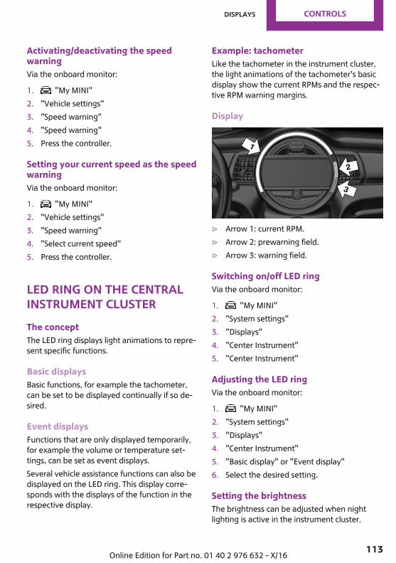
Activating/deactivating the speedwarningVia the onboard monitor:
1. "My MINI"2. "Vehicle settings"3. "Speed warning"4. "Speed warning"5. Press the controller.
Setting your current speed as the speedwarningVia the onboard monitor:
1. "My MINI"2. "Vehicle settings"3. "Speed warning"4. "Select current speed"5. Press the controller.
LED ring on the centralinstrument clusterThe conceptThe LED ring displays light animations to repre‐sent specific functions.
Basic displaysBasic functions, for example the tachometer,can be set to be displayed continually if so de‐sired.
Event displaysFunctions that are only displayed temporarily,for example the volume or temperature set‐tings, can be set as event displays.Several vehicle assistance functions can also bedisplayed on the LED ring. This display corre‐sponds with the displays of the function in therespective display.
Example: tachometerLike the tachometer in the instrument cluster,the light animations of the tachometer's basicdisplay show the current RPMs and the respec‐tive RPM warning margins.
Display
▷ Arrow 1: current RPM.▷ Arrow 2: prewarning field.▷ Arrow 3: warning field.
Switching on/off LED ringVia the onboard monitor:
1. "My MINI"2. "System settings"3. "Displays"4. "Center Instrument"5. "Center Instrument"
Adjusting the LED ringVia the onboard monitor:
1. "My MINI"2. "System settings"3. "Displays"4. "Center Instrument"5. "Basic display" or "Event display"6. Select the desired setting.
Setting the brightnessThe brightness can be adjusted when nightlighting is active in the instrument cluster.
Seite 113
Displays CONTROLS
113Online Edition for Part no. 01 40 2 976 632 - X/16
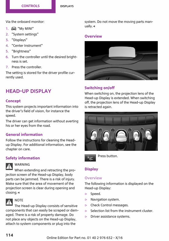
Via the onboard monitor:
1. "My MINI"2. "System settings"3. "Displays"4. "Center Instrument"5. "Brightness"6. Turn the controller until the desired bright‐
ness is set.7. Press the controller.The setting is stored for the driver profile cur‐rently used.
Head-up DisplayConceptThis system projects important information intothe driver's field of vision, for instance thespeed.The driver can get information without avertinghis or her eyes from the road.
General informationFollow the instructions for cleaning the Head-up Display. For additional information, see thechapter on care.
Safety informationWARNINGWhen extending and retracting the pro‐
jection screen of the Head-up Display, bodyparts can be jammed. There is a risk of injury.Make sure that the area of movement of theprojection screen is clear during opening andclosing.◀
NOTEThe Head-up Display consists of sensitive
components that can easily be scraped or dam‐aged. There is a risk of property damage. Donot place any objects on the Head-up Display,attach to system components or plug into the
system. Do not move the moving parts man‐ually.◀
Overview
Switching on/offWhen switching on, the projection lens of theHead-up Display is extended. When switchingoff, the projection lens of the Head-up Displayis retracted again.
Press button.
Display
OverviewThe following information is displayed on theHead-up Display:▷ Speed.▷ Navigation system.▷ Check Control messages.▷ Selection list from the instrument cluster.▷ Driver assistance systems.
Seite 114
CONTROLS Displays
114 Online Edition for Part no. 01 40 2 976 632 - X/16
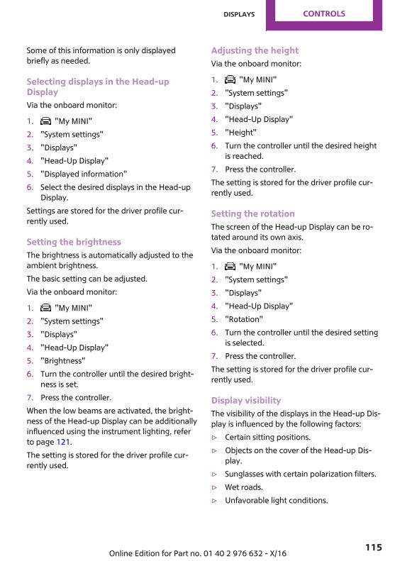
Some of this information is only displayedbriefly as needed.
Selecting displays in the Head-upDisplayVia the onboard monitor:
1. "My MINI"2. "System settings"3. "Displays"4. "Head-Up Display"5. "Displayed information"6. Select the desired displays in the Head-up
Display.Settings are stored for the driver profile cur‐rently used.
Setting the brightnessThe brightness is automatically adjusted to theambient brightness.The basic setting can be adjusted.Via the onboard monitor:
1. "My MINI"2. "System settings"3. "Displays"4. "Head-Up Display"5. "Brightness"6. Turn the controller until the desired bright‐
ness is set.7. Press the controller.When the low beams are activated, the bright‐ness of the Head-up Display can be additionallyinfluenced using the instrument lighting, referto page 121.The setting is stored for the driver profile cur‐rently used.
Adjusting the heightVia the onboard monitor:
1. "My MINI"2. "System settings"3. "Displays"4. "Head-Up Display"5. "Height"6. Turn the controller until the desired height
is reached.7. Press the controller.The setting is stored for the driver profile cur‐rently used.
Setting the rotationThe screen of the Head-up Display can be ro‐tated around its own axis.Via the onboard monitor:
1. "My MINI"2. "System settings"3. "Displays"4. "Head-Up Display"5. "Rotation"6. Turn the controller until the desired setting
is selected.7. Press the controller.The setting is stored for the driver profile cur‐rently used.
Display visibilityThe visibility of the displays in the Head-up Dis‐play is influenced by the following factors:▷ Certain sitting positions.▷ Objects on the cover of the Head-up Dis‐
play.▷ Sunglasses with certain polarization filters.▷ Wet roads.▷ Unfavorable light conditions.
Seite 115
Displays CONTROLS
115Online Edition for Part no. 01 40 2 976 632 - X/16
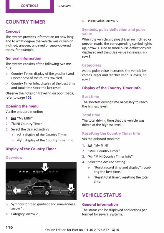
Country timerConceptThe system provides information on how longand to what degree the vehicle was driven oninclined, uneven, unpaved or snow-coveredroads, for example.
General informationThe system consists of the following two me‐nus:▷ Country Timer: display of the gradient and
unevenness of the routes traveled.▷ Country Timer Info: display of the best time
and total time since the last reset.Observe the notes on traveling on poor roads,refer to page 193.
Opening the menuVia the onboard monitor:
1. "My MINI"2. "MINI Country Timer"3. Select the desired setting.
▷ : display of the Country Timer.▷ : display of the Country Timer Info.
Display of the Country Timer
Overview
▷ Symbols for road gradient and unevenness,arrow 1.
▷ Category, arrow 2.
▷ Pulse value, arrow 3.
Symbols, pulse deflection and pulsevalueWhen the vehicle is being driven on inclined oruneven roads, the corresponding symbol lightsup, arrow 1. One or more pulse deflections aredisplayed and the pulse value increases, ar‐row 3.
CategoriesAs the pulse value increases, the vehicle be‐comes larger and reaches various levels, ar‐row 2.
Display of the Country Timer Info
Best timeThe shortest driving time necessary to reachthe highest level.
Total timeThe total driving time that the vehicle wasdriven at the highest level.
Resetting the Country Timer InfoVia the onboard monitor:
1. "My MINI"2. "MINI Country Timer"3. "MINI Country Timer Info"4. Select the desired setting.
▷ "Reset record time and display": reset‐ting the best time.
▷ "Reset total time": resetting the totaltime.
Vehicle statusGeneral informationThe status can be displayed and actions per‐formed for several systems.
Seite 116
CONTROLS Displays
116 Online Edition for Part no. 01 40 2 976 632 - X/16

Opening the vehicle statusVia the onboard monitor:
1. "My MINI"2. "Vehicle status"
Information at a glance▷ "Flat Tire Monitor": Status of the Flat
Tire Monitor, refer to page 131.▷ "Tire Pressure Monitor": Status of the
Tire Pressure Monitor, refer to page 127.▷ Resetting the Tire Pressure Monitor, refer to
page 127.▷ "Engine oil level": Electronic engine
oil level check, refer to page 226.▷ "Check Control": Check Control mes‐
sages are stored in the background and canbe displayed on the Control Display. Dis‐playing stored Check Control messages, re‐fer to page 104.
▷ "Service required": Displaying servicerequirements, refer to page 106.
Seite 117
Displays CONTROLS
117Online Edition for Part no. 01 40 2 976 632 - X/16
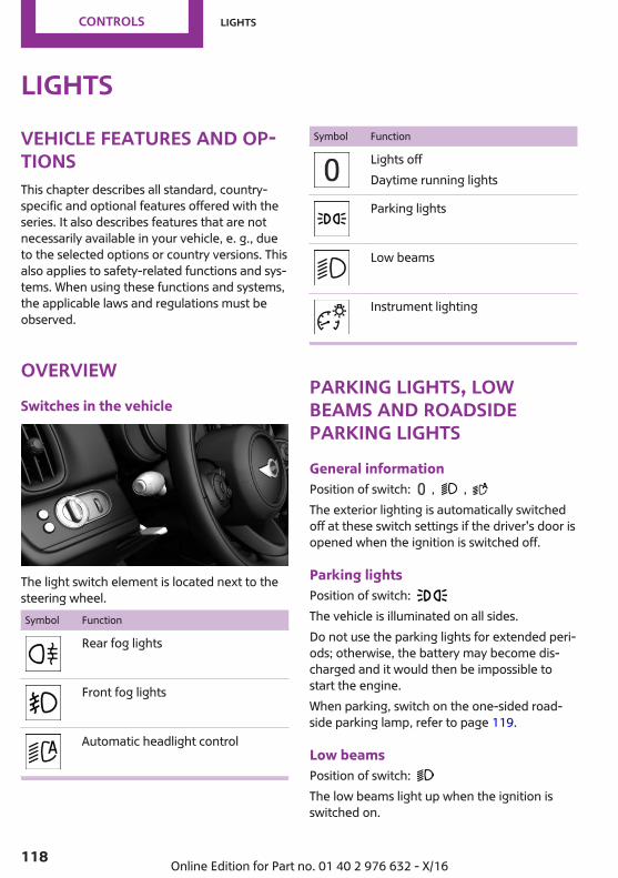
LightsVehicle features and op‐tionsThis chapter describes all standard, country-specific and optional features offered with theseries. It also describes features that are notnecessarily available in your vehicle, e. g., dueto the selected options or country versions. Thisalso applies to safety-related functions and sys‐tems. When using these functions and systems,the applicable laws and regulations must beobserved.
OverviewSwitches in the vehicle
The light switch element is located next to thesteering wheel.Symbol Function
Rear fog lights
Front fog lights
Automatic headlight control
Symbol Function
Lights offDaytime running lights
Parking lights
Low beams
Instrument lighting
Parking lights, lowbeams and roadsideparking lightsGeneral informationPosition of switch: , , The exterior lighting is automatically switchedoff at these switch settings if the driver's door isopened when the ignition is switched off.
Parking lightsPosition of switch: The vehicle is illuminated on all sides.Do not use the parking lights for extended peri‐ods; otherwise, the battery may become dis‐charged and it would then be impossible tostart the engine.When parking, switch on the one-sided road‐side parking lamp, refer to page 119.
Low beamsPosition of switch: The low beams light up when the ignition isswitched on.
Seite 118
CONTROLS Lights
118 Online Edition for Part no. 01 40 2 976 632 - X/16
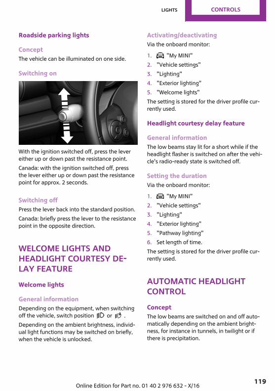
Roadside parking lights
ConceptThe vehicle can be illuminated on one side.
Switching on
With the ignition switched off, press the levereither up or down past the resistance point.Canada: with the ignition switched off, pressthe lever either up or down past the resistancepoint for approx. 2 seconds.
Switching offPress the lever back into the standard position.Canada: briefly press the lever to the resistancepoint in the opposite direction.
Welcome lights andheadlight courtesy de‐lay featureWelcome lights
General informationDepending on the equipment, when switchingoff the vehicle, switch position or .Depending on the ambient brightness, individ‐ual light functions may be switched on briefly,when the vehicle is unlocked.
Activating/deactivatingVia the onboard monitor:
1. "My MINI"2. "Vehicle settings"3. "Lighting"4. "Exterior lighting"5. "Welcome lights"The setting is stored for the driver profile cur‐rently used.
Headlight courtesy delay feature
General informationThe low beams stay lit for a short while if theheadlight flasher is switched on after the vehi‐cle's radio-ready state is switched off.
Setting the durationVia the onboard monitor:
1. "My MINI"2. "Vehicle settings"3. "Lighting"4. "Exterior lighting"5. "Pathway lighting"6. Set length of time.The setting is stored for the driver profile cur‐rently used.
Automatic headlightcontrolConceptThe low beams are switched on and off auto‐matically depending on the ambient bright‐ness, for instance in tunnels, in twilight or ifthere is precipitation.
Seite 119
Lights CONTROLS
119Online Edition for Part no. 01 40 2 976 632 - X/16
General informationA blue sky with the sun low on the horizon cancause the lights to be switched on.
ActivatingPosition of switch: The indicator light in the instrument cluster is il‐luminated when the low beams are switchedon.
System limitsThe automatic headlight control cannot serveas a substitute for your personal judgment oflighting conditions.For example, the sensors are unable to detectfog or hazy weather. To avoid safety risks underthese conditions, you should always switch onthe lights manually.
Daytime running lightsGeneral informationPosition of switch: , , The daytime running lights light up when theignition is switched on. After the ignition isswitched off, the parking lights light up in posi‐tion .
Activating/deactivatingIn some countries, daytime running lights aremandatory, so it may not be possible to deacti‐vate the daytime running lights.Via the onboard monitor:
1. "My MINI"2. "Vehicle settings"3. "Lighting"4. "Exterior lighting"5. Select the desired setting.Settings are stored for the remote control cur‐rently used.
Cornering lightGeneral informationPosition of switch: When going around corners, the cornering lightalso lights the interior area of the curve. Belowa speed of approx. 25 mph/40 km/h when theturn signal is switched on and the steering an‐gle is detected, there is automatic activation.
MalfunctionA Check Control message is displayed.Cornering light is malfunctioning or has failed.Have the system immediately checked by adealer’s service center or another qualifiedservice center or repair shop.
Self-leveling headlightsThe self-leveling headlights compensate for ac‐celeration and braking operations in order notto blind the oncoming traffic and to achieveoptimum illumination of the roadway.
High-beam AssistantConceptThe high-beam Assistant detects other trafficparticipants early on and automaticallyswitches the high beams on or off dependingon the traffic situation. The assistant ensuresthat the high beams are switched on, wheneverthe traffic situation allows. In the low speedrange, the high beams are not switched on bythe system.
General informationThe system responds to light from oncomingtraffic and traffic driving ahead of you, and toadequate illumination, for instance in townsand cities.
Seite 120
CONTROLS Lights
120 Online Edition for Part no. 01 40 2 976 632 - X/16
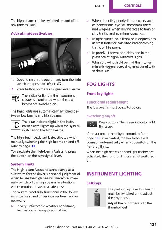
The high beams can be switched on and off atany time as usual.
Activating/deactivating
1. Depending on the equipment, turn the lightswitch into position or .
2. Press button on the turn signal lever, arrow.The indicator light in the instrumentcluster is illuminated when the lowbeams are switched on.
The headlights are automatically switched be‐tween low beams and high beams.
The blue indicator light in the instru‐ment cluster lights up when the systemswitches on the high beams.
The high-beam Assistant is deactivated whenmanually switching the high beams on and off,refer to page 88.To reactivate the high-beam Assistant, pressthe button on the turn signal lever.
System limitsThe High-beam Assistant cannot serve as asubstitute for the driver's personal judgment ofwhen to use the high beams. Therefore, man‐ually switch off the high beams in situationswhere required to avoid a safety risk.The system is not fully functional in the follow‐ing situations, and driver intervention may benecessary:▷ In very unfavorable weather conditions,
such as fog or heavy precipitation.
▷ When detecting poorly-lit road users suchas pedestrians, cyclists, horseback ridersand wagons; when driving close to train orship traffic; and at animal crossings.
▷ In tight curves, on hilltops or in depressions,in cross traffic or half-obscured oncomingtraffic on highways.
▷ In poorly-lit towns and cities and in thepresence of highly reflective signs.
▷ When the windshield behind the interiormirror is fogged over, dirty or covered withstickers, etc.
Fog lightsFront fog lights
Functional requirementThe low beams must be switched on.
Switching on/offPress button. The green indicator lightlights up.
If the automatic headlight control, refer topage 119, is activated, the low beams willcome on automatically when you switch on thefront fog lights.When the high beams or headlight flasher areactivated, the front fog lights are not switchedon.
Instrument lightingSettings
The parking lights or low beamsmust be switched on to adjustthe brightness.Adjust the brightness with thethumbwheel.
Seite 121
Lights CONTROLS
121Online Edition for Part no. 01 40 2 976 632 - X/16

Interior lightsGeneral informationDepending on the equipment, the interiorlights, footwell lights, entry lights, and courtesylights are controlled automatically.Thumb wheel for the instrument lighting con‐trols brightness of some of these features.
Overview
1 Interior lights2 Reading lights3 Ambient light
Switching interior lights on/offmanually
Press button.
To switch off permanently: press the button forapprox. 3 seconds.Switch back on: press button.
Switching the reading lights on and offmanually
Press button.
Reading lights are located in the front next tothe interior light.
Ambient light
General informationDepending on your optional features lightingcan be adjusted for some lights in the interior.
Activating/deactivatingVia the onboard monitor:
1. "My MINI"2. "Vehicle settings"3. "Lighting"4. "Interior lighting"5. "Ambient lighting"6. Select the desired setting.Settings are stored for the profile currentlyused.
Changing colorPush the switch forward or back: man‐ual color change.
Push and hold the switch forward orback: automatic color change. Push
the switch again to end color changes.
Setting the brightnessDepending on the equipment, the brightness ofthe ambient light can be adjusted via thethumbwheel for the instrument lighting or onthe Control Display.Via the onboard monitor:
1. "My MINI"2. "Vehicle settings"3. "Lighting"4. "Interior lighting"5. "Brightness"6. Adjust the brightness.
Seite 122
CONTROLS Lights
122 Online Edition for Part no. 01 40 2 976 632 - X/16
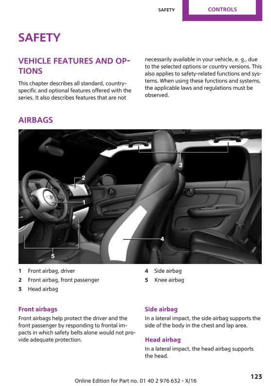
SafetyVehicle features and op‐tionsThis chapter describes all standard, country-specific and optional features offered with theseries. It also describes features that are not
necessarily available in your vehicle, e. g., dueto the selected options or country versions. Thisalso applies to safety-related functions and sys‐tems. When using these functions and systems,the applicable laws and regulations must beobserved.
Airbags
1 Front airbag, driver2 Front airbag, front passenger3 Head airbag
4 Side airbag5 Knee airbag
Front airbagsFront airbags help protect the driver and thefront passenger by responding to frontal im‐pacts in which safety belts alone would not pro‐vide adequate protection.
Side airbagIn a lateral impact, the side airbag supports theside of the body in the chest and lap area.
Head airbagIn a lateral impact, the head airbag supportsthe head.
Seite 123
Safety CONTROLS
123Online Edition for Part no. 01 40 2 976 632 - X/16
Ejection MitigationThe head airbag system is designed as an ejec‐tion mitigation countermeasure to reduce thelikelihood of ejections of vehicle occupantsthrough side windows during rollovers or sideimpact events.
Knee airbagThe knee airbag supports the legs in a frontalimpact.
Protective actionAirbags are not triggered in every impact situa‐tion, e.g., in less severe accidents or rear-endcollisions.
Information on optimum effect of theairbags
WARNINGIf the seat position is incorrect or the de‐
ployment area of the airbags is impaired, theairbag system cannot provide protection as in‐tended and may cause additional injuries dueto triggering. There is a risk of injuries or dan‐ger to life. Follow the information on optimumprotective effect of the airbag system.◀
▷ Keep a distance from the airbags.▷ Make sure that occupants keep their heads
away from the side airbag.▷ Always grasp the steering wheel on the
steering wheel rim. Hold your hands at the3 o'clock and 9 o'clock positions, to keepthe risk of injury to your hands or arms aslow as possible when the airbag is trig‐gered.
▷ Make sure that the front passenger is sittingcorrectly, i.e., keeps his or her feet and legsin the floor area and does not support themon the dashboard.
▷ There should be no additional persons, ani‐mals or objects between an airbag and aperson.
▷ Do not apply adhesive materials to the air‐bag cover panels, do not cover them ormodify them in any way.
▷ Dashboard and windshield on the frontpassenger side must stay clear - do not at‐tach adhesive labels or coverings and donot attach brackets or cables, for instancefor GPS devices or mobile phones.
▷ Do not use the cover of the front airbag onthe front passenger side as a storage area.
▷ Do not place slip covers, seat cushions orother objects on the front passenger seatthat are not specifically suited for seats withintegrated side airbags.
▷ Do not hang pieces of clothing, such asjackets, over the backrests.
▷ Never modify either the individual compo‐nents or the wiring in the airbag system.This also applies to steering wheel covers,the dashboard, and the seats.
▷ Do not remove the airbag system.Even when you follow all instructions veryclosely, injury from contact with the airbagscannot be fully ruled out in certain situations.The ignition and inflation noise may lead toshort-term and, in most cases, temporary hear‐ing impairment in sensitive occupants.Vehicle modifications for a person with disabili‐ties may affect the air bag system; therefore,contact MINI Customer Relations or your au‐thorized MINI service center.Warnings and information on the airbags arealso found on the sun visors.
Seite 124
CONTROLS Safety
124 Online Edition for Part no. 01 40 2 976 632 - X/16
Functional readiness of the airbagsystem
Safety informationWARNINGIndividual components can be hot after
triggering of the airbag system. There is a riskof injury. Do not touch individual compo‐nents.◀
WARNINGImproperly executed work can lead to
failure, malfunction or unintentional triggeringof the airbag system. In the case of a malfunc‐tion, the airbag system might not trigger as in‐tended in the event of an accident despite re‐spective accident severity. There is a risk ofinjuries or danger to life. Have the airbag sys‐tem checked, repaired, dismantled and scrap‐ped by a dealer’s service center or anotherqualified service center or repair shop.◀
Correct functionWhen the ignition is switched on, thewarning lamp in the instrument clusterlights up briefly and thereby indicates
the operational readiness of the entire airbagsystem and the belt tensioner.
Airbag system malfunctioning▷ Warning lamp does not come on when the
ignition is turned on.▷ The warning lamp lights up continuously.
Automatic deactivation of the front-seat passenger airbags
The conceptThe system reads if the front passenger seat isoccupied by measuring the human body's re‐sistance.
Front, knee and side airbag on the front pas‐senger's side are either activated or deacti‐vated.
General informationBefore transporting a child on the front passen‐ger seat, refer to the safety notes and instruc‐tions for children on the front passenger seat,see Children.
Safety informationWARNINGTo ensure the front-seat passenger airbag
function, the system must be able to detectwhether a person is sitting in the front passen‐ger seat. The entire seat cushion area must beused for this purpose. There is a risk of injuriesor danger to life. Make sure that the front pas‐senger keeps his or her feet in the floor area.◀
Malfunction of the automaticdeactivation systemWhen transporting older children and adults,the front-seat passenger airbags may be deac‐tivated in certain sitting positions. In this case,the indicator lamp for the front-seat passengerairbags lights up.In this case, change the sitting position so thatthe front-seat passenger airbags are activatedand the indicator lamp goes out.If it is not possible to activate the airbags, havethe person sit in the rear.To enable correct recognition of the occupiedseat cushion.▷ Do not attach covers, cushions, ball mats or
other items to the front passenger seat un‐less they are specifically determined to besafe for use on the front passenger seat.
▷ Do not place any electronic devices on thepassenger seat if a child restraint system isto be installed on it.
▷ Do not place objects under the seat thatcould press against the seat from below.
Seite 125
Safety CONTROLS
125Online Edition for Part no. 01 40 2 976 632 - X/16
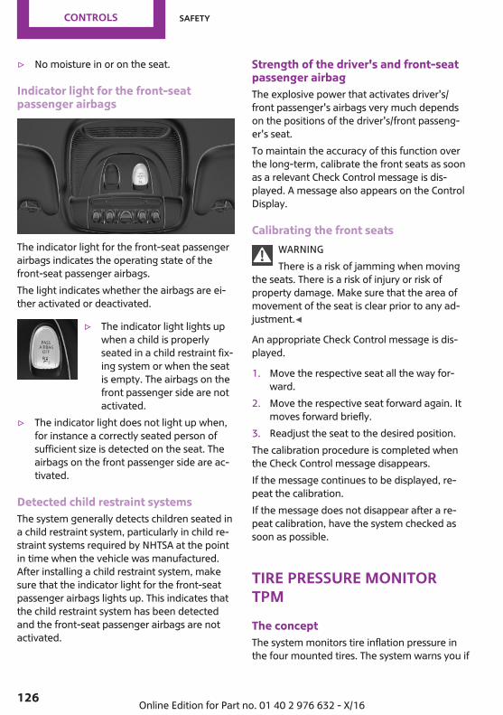
▷ No moisture in or on the seat.
Indicator light for the front-seatpassenger airbags
The indicator light for the front-seat passengerairbags indicates the operating state of thefront-seat passenger airbags.The light indicates whether the airbags are ei‐ther activated or deactivated.
▷ The indicator light lights upwhen a child is properlyseated in a child restraint fix‐ing system or when the seatis empty. The airbags on thefront passenger side are notactivated.
▷ The indicator light does not light up when,for instance a correctly seated person ofsufficient size is detected on the seat. Theairbags on the front passenger side are ac‐tivated.
Detected child restraint systemsThe system generally detects children seated ina child restraint system, particularly in child re‐straint systems required by NHTSA at the pointin time when the vehicle was manufactured.After installing a child restraint system, makesure that the indicator light for the front-seatpassenger airbags lights up. This indicates thatthe child restraint system has been detectedand the front-seat passenger airbags are notactivated.
Strength of the driver's and front-seatpassenger airbagThe explosive power that activates driver's/front passenger's airbags very much dependson the positions of the driver's/front passeng‐er's seat.To maintain the accuracy of this function overthe long-term, calibrate the front seats as soonas a relevant Check Control message is dis‐played. A message also appears on the ControlDisplay.
Calibrating the front seatsWARNINGThere is a risk of jamming when moving
the seats. There is a risk of injury or risk ofproperty damage. Make sure that the area ofmovement of the seat is clear prior to any ad‐justment.◀
An appropriate Check Control message is dis‐played.
1. Move the respective seat all the way for‐ward.
2. Move the respective seat forward again. Itmoves forward briefly.
3. Readjust the seat to the desired position.The calibration procedure is completed whenthe Check Control message disappears.If the message continues to be displayed, re‐peat the calibration.If the message does not disappear after a re‐peat calibration, have the system checked assoon as possible.
Tire Pressure MonitorTPMThe conceptThe system monitors tire inflation pressure inthe four mounted tires. The system warns you if
Seite 126
CONTROLS Safety
126 Online Edition for Part no. 01 40 2 976 632 - X/16

there is a significant loss of pressure in one ormore tires. For this purpose, sensors in the tirevalves measure the tire inflation pressure.
General informationWith use of the system observe further infor‐mation found under Tire inflation pressure, re‐fer to page 208.
Functional requirementsThe system must have been reset with the cor‐rect tire inflation pressure; otherwise, reliablesignaling of tire pressure loss is not assured.Reset the system after each adjustment of thetire inflation pressure and after every tire orwheel change.Always use wheels with TPM electronics to en‐sure that the system will operate properly.
Status displayThe current status of the Tire Pressure MonitorTPM can be displayed on the Control Display,for instance whether or not the TPM is active.Via the onboard monitor:
1. "My MINI"2. "Vehicle status"3. "Tire Pressure Monitor"The status is displayed.
Status control displayTire and system status are indicated by thecolor of the tires and a SMS text message onthe Control Display.
All wheels greenSystem is active and will issue a warning basedon the tire inflation pressures stored during thelast reset.
One wheel is yellowA flat tire or major drop in inflation pressure inthe indicated tire.
All wheels are yellowA flat tire or major drop in inflation pressure inseveral tires.
Wheels, grayThe system cannot detect a flat tire due to amalfunction.
Status informationThe status control display additionally showsthe current tire inflation pressures. It shows theactual values read; they may vary dependingon driving style or weather conditions.
Resetting the systemReset the system after each adjustment of thetire inflation pressure and after every tire orwheel change.Via the onboard monitor:
1. "My MINI"2. "Vehicle status"3. "Tire Pressure Monitor"4. Start the engine but do not drive off.5. Reset the tire inflation pressure using
"Perform reset".6. Drive away.The tires are shown in gray and the status isdisplayed.After driving faster than 19 mph/30 km/h for ashort period, the set tire inflation pressures areaccepted as reference values. The resettingprocess is completed automatically while driv‐ing. After successful completion of the reset,the tires appear in green on the Control Displayand "Tire Pressure Monitor active. See label forrecommended pressures." is displayed.The progress of the reset is displayed.You may interrupt this trip at any time. Whenyou continue the reset resumes automatically.
Seite 127
Safety CONTROLS
127Online Edition for Part no. 01 40 2 976 632 - X/16

Messages
Required tire inflation pressure checkmessage
A Check Control message is displayed.▷ The system has detected a wheel
change, but no reset was done.▷ No reset was performed for the system. The
system issues a warning based on the tireinflation pressures stored during the last re‐set.
▷ Inflation was not carried out according tospecifications.
A Check Control message is displayed.The tire inflation pressure has fallen be‐low the level of the last reset.
In these cases:
1. Check the tire pressure and correct asneeded.
2. Perform a system reset.
Message in case of low tire pressureThe yellow warning lamp lights up.
A Check Control message is displayed.
▷ There is a tire inflation pressure loss.▷ No reset was performed for the system. The
system issues a warning based on the tireinflation pressures stored during the last re‐set.
In these cases:
1. Reduce your speed and drive moderately.Do not exceed a speed of80 mph/130 km/h.
2. At the next opportunity, e.g., gas station,check and correct the tire inflation pressurein all four tires, if necessary.
3. Reset the system.
Message in case of sharp tire inflationpressure loss
The yellow warning lamp lights up.A symbol with the affected tires will bedisplayed in the Check Control mes‐
sage.
▷ There is a flat tire or a major loss in tire in‐flation pressure.
▷ No reset was performed for the system. Thesystem issues a warning based on the tireinflation pressures stored during the last re‐set.
In these cases:
1. Reduce your speed and stop cautiously.Avoid sudden braking and steering maneu‐vers.
2. Check whether the vehicle is fitted withnormal tires or run-flat tires.Run-flat tires, refer to page 215, are la‐beled with a circular symbol containing theletters RSC marked on the tire's sidewall.
WARNINGA damaged regular tire with low or miss‐
ing tire inflation pressure impacts handling,such as steering and braking response. Run-flattires can maintain limited stability. There is arisk of an accident. Do not continue driving ifthe vehicle is equipped with normal tires. Fol‐low the information on run-flat tires and con‐tinued driving with these tires.◀
A low tire inflation pressure might turn on DSCDynamic Stability Control.
Actions in the event of a flat tire
Normal tires1. Identify the damaged tire.
Seite 128
CONTROLS Safety
128 Online Edition for Part no. 01 40 2 976 632 - X/16
Check the air pressure in all four tires, forinstance using the tire pressure gage of atire repair kit.If the tire inflation pressure in all four tires iscorrect, the Tire Pressure Monitor may nothave been initialized. In this case, initializethe system.If identification of flat tire damage is notpossible, please contact a dealer’s servicecenter or another qualified service center orrepair shop.
2. Repair the flat tire, for instance with a tirerepair kit or by changing the tire.
Use of sealant, for instance from the tire repairkit, may damage the TPM wheel electronics. Inthis case, have the electronics checked and re‐placed at the next opportunity.
Run-flat tires
Maximum speedYou may continue driving with a damaged tireat speeds up to 50 mph/80 km/h.
Continued driving with a flat tireIf continuing to drive with a damaged tire:
1. Avoid sudden braking and steering maneu‐vers.
2. Do not exceed a speed of 50 mph/80 km/h.3. Check the air pressure in all four tires at the
next opportunity.If the tire inflation pressure in all four tires iscorrect, the Tire Pressure Monitor may nothave been reset. In this case, perform thereset.
Possible driving distance with complete loss oftire inflation pressure:The possible driving range varies depending onthe how the vehicle is loaded and used, e.g.,speed, road conditions, external temperature.The driving range may be less but may also bemore if an economical driving style is used.
If the vehicle is loaded with an average weightand used under favorable conditions, its possi‐ble driving range will be up to 50 miles/80 km.A vehicle with a damaged tire reacts differently,for instance it has reduced lane stability duringbraking, a longer braking distance and differentself-steering properties. Adjust your drivingstyle accordingly. Avoid abrupt steering ma‐neuvers or driving over obstacles, for instancecurbs, potholes, etc.
WARNINGYour vehicle handles differently with a
runflat with no or low inflation pressure; for in‐stance, your lane stability when braking is re‐duced, braking distances are longer and theself-steering properties will change. There is arisk of an accident.Drive moderately and do not exceed a speed of50 mph/80 km/h.◀
Final tire failureVibrations or loud noises while driving can indi‐cate the final failure of a tire.Reduce speed and stop; otherwise, pieces ofthe tire could come loose and cause an acci‐dent.Do not continue driving. Contact a dealer’sservice center or another qualified service cen‐ter or repair shop.
System limitsThe system does not function properly if a resethas not been carried out, e.g., a flat tire is re‐ported though tire inflation pressures are cor‐rect.The tire inflation pressure depends on the tire'stemperature. Driving or exposure to the sunwill increase the tire's temperature, thus in‐creasing the tire inflation pressure. The tire in‐flation pressure is reduced when the tire tem‐perature falls again. These circumstances maycause a warning when temperatures fall verysharply.
Seite 129
Safety CONTROLS
129Online Edition for Part no. 01 40 2 976 632 - X/16

The system cannot indicate sudden serious tiredamage caused by external circumstances.
MalfunctionThe yellow warning lamp flashes andthen lights up continuously. A CheckControl message is displayed. No flat
tire or loss of tire pressure can be detected.Examples and recommendations in the follow‐ing situations:▷ A wheel without TPM electronics, for exam‐
ple an emergency wheel, is mounted: Haveit checked by a dealer’s service center oranother qualified service center or repairshop as needed.
▷ Malfunction: Have system checked by adealer’s service center or another qualifiedservice center or repair shop.
▷ TPM was unable to complete the reset. Re‐set the system again.
▷ Interference through systems or deviceswith the same radio frequency: After leav‐ing the area of the interference, the systemautomatically becomes active again.
Declaration according to NHTSA/FMVSS138 Tire Pressure Monitoring SystemEach tire, including the spare (if provided)should be checked monthly when cold and in‐flated to the inflation pressure recommendedby the vehicle manufacturer on the vehicleplacard or tire inflation pressure label. (If yourvehicle has tires of a different size than the sizeindicated on the vehicle placard or tire inflationpressure label, you should determine theproper tire inflation pressure for those tires.) Asan added safety feature, your vehicle has beenequipped with a tire pressure monitoring sys‐tem (TPMS) that illuminates a low tire pressuretelltale when one or more of your tires is signifi‐cantly under-inflated. Accordingly, when thelow tire pressure telltale illuminates, you shouldstop and check your tires as soon as possible,and inflate them to the proper pressure. Driving
on a significantly under-inflated tire causes thetire to overheat and can lead to tire failure. Un‐der-inflation also reduces fuel efficiency andtire tread life, and may affect the vehicle's han‐dling and stopping ability. Please note that theTPMS is not a substitute for proper tire mainte‐nance, and it is the driver's responsibility tomaintain correct tire pressure, even if under-in‐flation has not reached the level to trigger illu‐mination of the TPMS low tire pressure telltale.Your vehicle has also been equipped with aTPMS malfunction indicator to indicate whenthe system is not operating properly. The TPMSmalfunction indicator is combined with the lowtire pressure telltale. When the system detectsa malfunction, the telltale will flash for approxi‐mately one minute and then remain continu‐ously illuminated. This sequence will continueupon subsequent vehicle start-ups as long asthe malfunction exists. When the malfunctionindicator is illuminated, the system may not beable to detect or signal low tire pressure as in‐tended. TPMS malfunctions may occur for a va‐riety of reasons, including the installation of re‐placement or alternate tires or wheels on thevehicle that prevent the TPMS from functioningproperly. Always check the TPMS malfunctiontelltale after replacing one or more tires orwheels on your vehicle to ensure that the re‐placement or alternate tires and wheels allowthe TPMS to continue to function properly.
FTM Flat Tire MonitorThe conceptThe system does not measure the actual infla‐tion pressure in the tires.It detects a tire inflation pressure loss by com‐paring the rotational speeds of the individualwheels while moving.In the event of a tire inflation pressure loss, thediameter and therefore the rotational speed ofthe corresponding wheel changes. This will bedetected and reported as a flat tire.
Seite 130
CONTROLS Safety
130 Online Edition for Part no. 01 40 2 976 632 - X/16
Functional requirementsThe system must have been initialized whenthe tire inflation pressure was correct; other‐wise, reliable flagging of a flat tire is not as‐sured. Initialize the system after each correc‐tion of the tire inflation pressure and afterevery tire or wheel change.
Status displayThe current status of the Flat Tire Monitor canbe displayed on the Control Display, for in‐stance whether or not the FTM is active.Via the onboard monitor:
1. "My MINI"2. "Vehicle status"3. "Flat Tire Monitor"The status is displayed.
InitializationWhen initializing, the set tire inflation pressuresserve as reference values in order to detect aflat tire. Initialization is started by confirmingthe inflation pressures.Do not initialize the system when driving withsnow chains.Via the onboard monitor:
1. "My MINI"2. "Vehicle status"3. "Flat Tire Monitor"4. Start the engine but do not drive off.5. Start the initialization with "Perform reset".6. Drive away.The initialization is completed while driving,which can be interrupted at any time.The initialization automatically continues whendriving resumes.
Indication of a flat tireThe yellow warning lamp lights up. ACheck Control message is displayed.
There is a flat tire or a major loss in tire inflationpressure.
1. Reduce your speed and stop cautiously.Avoid sudden braking and steering maneu‐vers.
2. Check whether the vehicle is fitted withnormal tires or run-flat tires.Run-flat tires, refer to page 215, are la‐beled with a circular symbol containing theletters RSC marked on the tire's sidewall.
WARNINGA damaged regular tire with low or miss‐
ing tire inflation pressure impacts handling,such as steering and braking response. Run-flattires can maintain limited stability. There is arisk of an accident. Do not continue driving ifthe vehicle is equipped with normal tires. Fol‐low the information on run-flat tires and con‐tinued driving with these tires.◀
When a flat tire is indicated, DSC Dynamic Sta‐bility Control is switched on if needed.
System limitsA natural, even tire inflation pressure loss in allfour tires will not be recognized. Therefore,check the tire inflation pressure regularly.Sudden serious tire damage caused by externalcircumstances cannot be recognized in ad‐vance.The system could be delayed or malfunction inthe following situations:▷ When the system has not been initialized.▷ When driving on a snowy or slippery road
surface.▷ Sporty driving style: spinning traction
wheels, high lateral acceleration (drifting).▷ When driving with snow chains.
Seite 131
Safety CONTROLS
131Online Edition for Part no. 01 40 2 976 632 - X/16
Actions in the event of a flat tire
Normal tires1. Identify the damaged tire.
Check the air pressure in all four tires, e.g.using the tire pressure gage of a tire repairkit.If the tire inflation pressure in all four tires iscorrect, the Flat Tire Monitor may not havebeen initialized. In this case, initialize thesystem.If identification of flat tire damage is notpossible, please contact a dealer’s servicecenter or another qualified service center orrepair shop.
2. Repair the flat tire, e.g. with a tire repair kitor by changing the tire.
Run-flat tires
Maximum speedYou may continue driving with a damaged tireat speeds up to 50 mph/80 km/h.
Continued driving with a flat tireIf continuing to drive with a damaged tire:
1. Avoid sudden braking and steering maneu‐vers.
2. Do not exceed a speed of 50 mph/80 km/h.3. Check the air pressure in all four tires at the
next opportunity.If the tire inflation pressure in all four tires iscorrect, the Flat Tire Monitor may not havebeen initialized. In this case, initialize thesystem.
Possible driving distance with complete loss oftire inflation pressure:The possible driving range varies depending onthe how the vehicle is loaded and used, e.g.,speed, road conditions, external temperature.The driving range may be less but may also bemore if an economical driving style is used.
If the vehicle is loaded with an average weightand used under favorable conditions, its possi‐ble driving range will be up to 50 miles/80 km.A vehicle with a damaged tire reacts differently,for instance it has reduced lane stability duringbraking, a longer braking distance and differentself-steering properties. Adjust your drivingstyle accordingly. Avoid abrupt steering ma‐neuvers or driving over obstacles, for instancecurbs, potholes, etc.
WARNINGYour vehicle handles differently with a
runflat with no or low inflation pressure; for in‐stance, your lane stability when braking is re‐duced, braking distances are longer and theself-steering properties will change. There is arisk of an accident.Drive moderately and do not exceed a speed of50 mph/80 km/h.◀
Final tire failureVibrations or loud noises while driving can indi‐cate the final failure of a tire.Reduce speed and stop; otherwise, pieces ofthe tire could come loose and cause an acci‐dent.Do not continue driving. Contact a dealer’sservice center or another qualified service cen‐ter or repair shop.
Intelligent SafetyConceptIntelligent Safety enables central operation ofthe driver assistance system.The intelligent safety systems can help preventan imminent collision.▷ Approach control warning with City light
braking function, refer to page 133.▷ Pedestrian warning with Approach control,
refer to page 136.
Seite 132
CONTROLS Safety
132 Online Edition for Part no. 01 40 2 976 632 - X/16
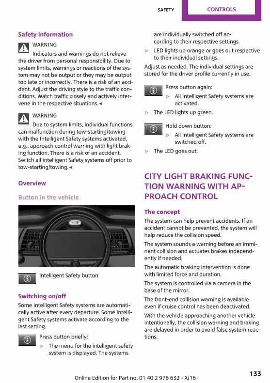
Safety informationWARNINGIndicators and warnings do not relieve
the driver from personal responsibility. Due tosystem limits, warnings or reactions of the sys‐tem may not be output or they may be outputtoo late or incorrectly. There is a risk of an acci‐dent. Adjust the driving style to the traffic con‐ditions. Watch traffic closely and actively inter‐vene in the respective situations.◀
WARNINGDue to system limits, individual functions
can malfunction during tow-starting/towingwith the Intelligent Safety systems activated,e.g., approach control warning with light brak‐ing function. There is a risk of an accident.Switch all Intelligent Safety systems off prior totow-starting/towing.◀
Overview
Button in the vehicle
Intelligent Safety button
Switching on/offSome Intelligent Safety systems are automati‐cally active after every departure. Some Intelli‐gent Safety systems activate according to thelast setting.
Press button briefly:▷ The menu for the intelligent safety
system is displayed. The systems
are individually switched off ac‐cording to their respective settings.
▷ LED lights up orange or goes out respectiveto their individual settings.
Adjust as needed. The individual settings arestored for the driver profile currently in use.
Press button again:▷ All Intelligent Safety systems are
activated.▷ The LED lights up green.
Hold down button:▷ All Intelligent Safety systems are
switched off.▷ The LED goes out.
City light braking func‐tion warning with Ap‐proach controlThe conceptThe system can help prevent accidents. If anaccident cannot be prevented, the system willhelp reduce the collision speed.The system sounds a warning before an immi‐nent collision and actuates brakes independ‐ently if needed.The automatic braking intervention is donewith limited force and duration.The system is controlled via a camera in thebase of the mirror.The front-end collision warning is availableeven if cruise control has been deactivated.With the vehicle approaching another vehicleintentionally, the collision warning and brakingare delayed in order to avoid false system reac‐tions.
Seite 133
Safety CONTROLS
133Online Edition for Part no. 01 40 2 976 632 - X/16
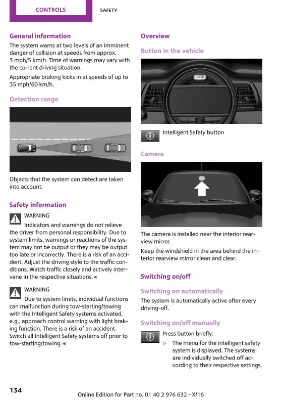
General informationThe system warns at two levels of an imminentdanger of collision at speeds from approx.3 mph/5 km/h. Time of warnings may vary withthe current driving situation.Appropriate braking kicks in at speeds of up to35 mph/60 km/h.
Detection range
Objects that the system can detect are takeninto account.
Safety informationWARNINGIndicators and warnings do not relieve
the driver from personal responsibility. Due tosystem limits, warnings or reactions of the sys‐tem may not be output or they may be outputtoo late or incorrectly. There is a risk of an acci‐dent. Adjust the driving style to the traffic con‐ditions. Watch traffic closely and actively inter‐vene in the respective situations.◀
WARNINGDue to system limits, individual functions
can malfunction during tow-starting/towingwith the Intelligent Safety systems activated,e.g., approach control warning with light brak‐ing function. There is a risk of an accident.Switch all Intelligent Safety systems off prior totow-starting/towing.◀
Overview
Button in the vehicle
Intelligent Safety button
Camera
The camera is installed near the interior rear‐view mirror.Keep the windshield in the area behind the in‐terior rearview mirror clean and clear.
Switching on/off
Switching on automaticallyThe system is automatically active after everydriving-off.
Switching on/off manuallyPress button briefly:▷ The menu for the intelligent safety
system is displayed. The systemsare individually switched off ac‐cording to their respective settings.
Seite 134
CONTROLS Safety
134 Online Edition for Part no. 01 40 2 976 632 - X/16
▷ LED lights up orange or goes out respectiveto their individual settings.
Adjust as needed. The individual settings arestored for the driver profile currently in use.
Press button again:▷ All Intelligent Safety systems are
activated.▷ The LED lights up green.
Hold down button:▷ All Intelligent Safety systems are
switched off.▷ The LED goes out.
Setting the warning timeThe warning time can be set via the onboardmonitor.
1. "My MINI"2. "Vehicle settings"3. "Intelligent Safety"4. "Warning time"5. Select the desired setting.The selected warning time is stored for thedriver profile currently in use.
Warning with braking function
DisplayA warning symbol appears in the instrumentcluster and in the Head-up Display if a collisionwith a detected vehicle is imminent.Symbol Measure
Symbol lights up red: prewarning.Brake and increase distance.
Symbol flashes red and an acousticsignal sounds: acute warning.You are requested to intervene bybraking or make an evasive maneu‐ver.
PrewarningThis warning is issued, for example, when thereis the impending danger of a collision or thedistance to the vehicle ahead is too small.The driver must intervene actively when thereis a prewarning.
Acute warning with braking functionAcute warning in displayed in case of the immi‐nent danger of a collision when the vehicle ap‐proaches another object at a high differentialspeed.The driver must intervene actively when thereis an acute warning. If necessary, the driver isassisted by a minor automatic braking inter‐vention in a possible risk of collision.Acute warnings can also be triggered withoutprevious forewarning.
Braking interventionThe warning prompts the driver himself/herselfto react. During a warning, the maximum brak‐ing force is used. Premise for the brake boosteris sufficiently quick and sufficiently hard step‐ping on the brake pedal. The system can assistwith some braking intervention if there is risk ofa collision. At low speeds vehicles may thuscome to a complete stop.Manual transmission: During a braking inter‐vention up to a complete stop, the engine maybe shut down.The braking intervention is executed only if ve‐hicle stability has not been restricted, e.g. bydeactivating the DSC Dynamic Stability Control.The braking intervention can be interrupted bystepping on the accelerator pedal or by activelymoving the steering wheel.Object detection can be restricted. Limitationsof the detection range and functional restric‐tions are to be considered.
Seite 135
Safety CONTROLS
135Online Edition for Part no. 01 40 2 976 632 - X/16
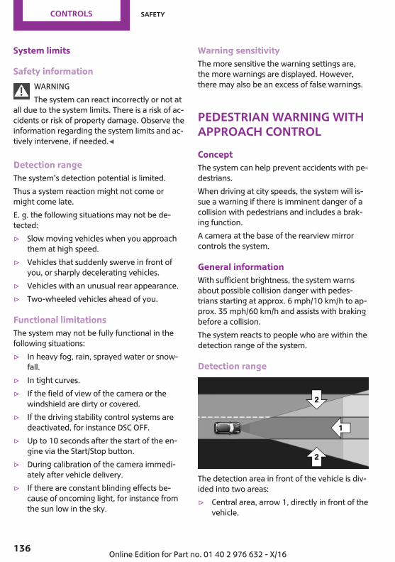
System limits
Safety informationWARNINGThe system can react incorrectly or not at
all due to the system limits. There is a risk of ac‐cidents or risk of property damage. Observe theinformation regarding the system limits and ac‐tively intervene, if needed.◀
Detection rangeThe system's detection potential is limited.Thus a system reaction might not come ormight come late.E. g. the following situations may not be de‐tected:▷ Slow moving vehicles when you approach
them at high speed.▷ Vehicles that suddenly swerve in front of
you, or sharply decelerating vehicles.▷ Vehicles with an unusual rear appearance.▷ Two-wheeled vehicles ahead of you.
Functional limitationsThe system may not be fully functional in thefollowing situations:▷ In heavy fog, rain, sprayed water or snow‐
fall.▷ In tight curves.▷ If the field of view of the camera or the
windshield are dirty or covered.▷ If the driving stability control systems are
deactivated, for instance DSC OFF.▷ Up to 10 seconds after the start of the en‐
gine via the Start/Stop button.▷ During calibration of the camera immedi‐
ately after vehicle delivery.▷ If there are constant blinding effects be‐
cause of oncoming light, for instance fromthe sun low in the sky.
Warning sensitivityThe more sensitive the warning settings are,the more warnings are displayed. However,there may also be an excess of false warnings.
Pedestrian warning withApproach controlConceptThe system can help prevent accidents with pe‐destrians.When driving at city speeds, the system will is‐sue a warning if there is imminent danger of acollision with pedestrians and includes a brak‐ing function.A camera at the base of the rearview mirrorcontrols the system.
General informationWith sufficient brightness, the system warnsabout possible collision danger with pedes‐trians starting at approx. 6 mph/10 km/h to ap‐prox. 35 mph/60 km/h and assists with brakingbefore a collision.The system reacts to people who are within thedetection range of the system.
Detection range
The detection area in front of the vehicle is div‐ided into two areas:▷ Central area, arrow 1, directly in front of the
vehicle.
Seite 136
CONTROLS Safety
136 Online Edition for Part no. 01 40 2 976 632 - X/16
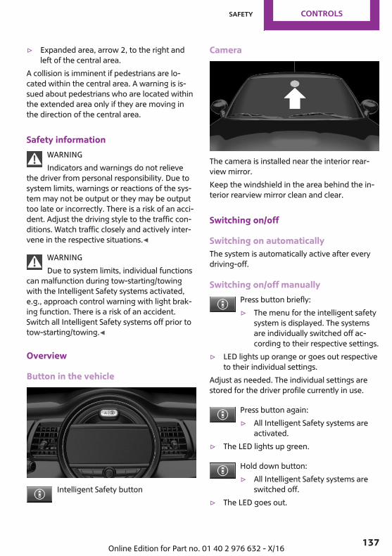
▷ Expanded area, arrow 2, to the right andleft of the central area.
A collision is imminent if pedestrians are lo‐cated within the central area. A warning is is‐sued about pedestrians who are located withinthe extended area only if they are moving inthe direction of the central area.
Safety informationWARNINGIndicators and warnings do not relieve
the driver from personal responsibility. Due tosystem limits, warnings or reactions of the sys‐tem may not be output or they may be outputtoo late or incorrectly. There is a risk of an acci‐dent. Adjust the driving style to the traffic con‐ditions. Watch traffic closely and actively inter‐vene in the respective situations.◀
WARNINGDue to system limits, individual functions
can malfunction during tow-starting/towingwith the Intelligent Safety systems activated,e.g., approach control warning with light brak‐ing function. There is a risk of an accident.Switch all Intelligent Safety systems off prior totow-starting/towing.◀
Overview
Button in the vehicle
Intelligent Safety button
Camera
The camera is installed near the interior rear‐view mirror.Keep the windshield in the area behind the in‐terior rearview mirror clean and clear.
Switching on/off
Switching on automaticallyThe system is automatically active after everydriving-off.
Switching on/off manuallyPress button briefly:▷ The menu for the intelligent safety
system is displayed. The systemsare individually switched off ac‐cording to their respective settings.
▷ LED lights up orange or goes out respectiveto their individual settings.
Adjust as needed. The individual settings arestored for the driver profile currently in use.
Press button again:▷ All Intelligent Safety systems are
activated.▷ The LED lights up green.
Hold down button:▷ All Intelligent Safety systems are
switched off.▷ The LED goes out.
Seite 137
Safety CONTROLS
137Online Edition for Part no. 01 40 2 976 632 - X/16
Warning with braking function
DisplayIf a collision with a person detected in this wayis imminent, a warning symbol appears on theinstrument cluster and in the Head-up Display.
The red symbol is displayed and a signalsounds.Intervene immediately by braking or
make an evasive maneuver.
Braking interventionThe warning prompts the driver himself/herselfto react. During a warning, the maximum brak‐ing force is used. Premise for the brake boosteris sufficiently quick and sufficiently hard step‐ping on the brake pedal. The system can assistwith some braking intervention if there is risk ofa collision. At low speeds vehicles may thuscome to a complete stop.Manual transmission: During a braking inter‐vention up to a complete stop, the engine maybe shut down.The braking intervention is executed only if ve‐hicle stability has not been restricted, e.g. bydeactivating the DSC Dynamic Stability Control.The braking intervention can be interrupted bystepping on the accelerator pedal or by activelymoving the steering wheel.Object detection can be restricted. Limitationsof the detection range and functional restric‐tions are to be considered.
System limits
Safety informationWARNINGThe system can react incorrectly or not at
all due to the system limits. There is a risk of ac‐cidents or risk of property damage. Observe theinformation regarding the system limits and ac‐tively intervene, if needed.◀
Detection rangeThe detection potential of the camera is lim‐ited.Thus a warning might not be issued or be is‐sued late.E. g. the following situations may not be de‐tected:▷ Partially covered pedestrians.▷ Pedestrians that are not detected as such
because of the viewing angle or contour.▷ Pedestrians outside of the detection range.▷ Pedestrians having a body size less than
32 inches/80 cm.
Functional limitationsThe system may not be fully functional or maynot be available in the following situations:▷ In heavy fog, rain, sprayed water or snow‐
fall.▷ In tight curves.▷ If the field of view of the camera or the
windshield are dirty or covered.▷ If the driving stability control systems are
deactivated, for instance DSC OFF.▷ Up to 10 seconds after the start of the en‐
gine via the Start/Stop button.▷ During calibration of the camera immedi‐
ately after vehicle delivery.▷ If there are constant blinding effects be‐
cause of oncoming light, for instance fromthe sun low in the sky.
▷ When it is dark outside.
Brake force displayConceptThe additional brake lamps tell following trafficthat an emergency braking procedure is beingperformed. This helps to reduce the risk of arear-end collision.
Seite 138
CONTROLS Safety
138 Online Edition for Part no. 01 40 2 976 632 - X/16

General information
▷ During normal brake application, the brakelights light up.
▷ During heavy brake application, the flash‐ers additionally light up.
Attentiveness assistantConceptThe system can detect decreasing alertness orfatigue of the driver during long, monotonoustrips, for instance on highways. In this situation,it is recommended that the driver takes abreak.
Safety informationWARNINGThe system does not release from the
personal responsibility to correctly assess one'sphysical state. An increasing lack of alertness orfatigue may not be detected or not be detectedin time. There is a risk of an accident. Makesure that the driver is rested and alert. Adjustthe driving style to the traffic conditions.◀
FunctionThe system is activated each time the engine isstarted and cannot be switched off.After travel has begun, the system monitorscertain aspects of the driver's behavior, so thatdecreasing alertness or fatigue can be de‐tected.
This procedure takes the following criteria intoaccount:▷ Personal driving style, for instance steering
behavior.▷ Driving conditions, for instance length of
trip.Starting at approximately 43 mph/70 km/h, thesystem is active and can display a recommen‐dation to take a break.
Break recommendationIf the driver becomes less alert or fatigued, amessage is displayed in the Control Display withthe recommendation to take a break.A recommendation to take a break is displayedonly once during an uninterrupted trip.After a break, another recommendation to takea break cannot be displayed until after approxi‐mately 45 minutes.
System limitsThe function may be limited in the following sit‐uations, for instance and will either output anincorrect warning or no warning at all:▷ When the clock is set incorrectly.▷ When the vehicle speed is mainly below
about 43 mph/70 km/h.▷ With a sporty driving style, such as during
rapid acceleration or when cornering fast.▷ In active driving situations, such as when
changing lanes frequently.▷ When the road surface is poor.▷ In the event of strong side winds.The system is reset approx. 45 minutes afterparking the vehicle, for instance in the case of abreak during longer trips on highways.
Post Crash — iBrakeDepressing the brake pedal can cause the vehi‐cle to brake harder. This interrupts automatic
Seite 139
Safety CONTROLS
139Online Edition for Part no. 01 40 2 976 632 - X/16
braking. Depressing the accelerator pedal alsointerrupts automatic braking.
ConceptIn the event of an accident, the system canbring the vehicle to a halt automatically with‐out intervention by the driver in certain situa‐tions. This can reduce the risk of a further colli‐sion and the consequences thereof.
At standstillAfter coming to a halt, the brake is released au‐tomatically. Secure the vehicle against rolling.
Harder vehicle brakingIt can be necessary to bring the vehicle in cer‐tain situations to a halt quicker.Here, a higher braking pressure must be gener‐ated for a short period when pressing the brakepedal than during automatic braking. This in‐terrupts automatic braking.
Interrupting automatic brakingIt can be necessary to interrupt automatic brak‐ing in certain situations, e.g., for an evasive ma‐neuver.Interrupt automatic braking:▷ By pressing the brake pedal.▷ By pressing the accelerator pedal.
Seite 140
CONTROLS Safety
140 Online Edition for Part no. 01 40 2 976 632 - X/16
Driving stability control systemsVehicle features and op‐tionsThis chapter describes all standard, country-specific and optional features offered with theseries. It also describes features that are notnecessarily available in your vehicle, e. g., dueto the selected options or country versions. Thisalso applies to safety-related functions and sys‐tems. When using these functions and systems,the applicable laws and regulations must beobserved.
Anti-lock Braking SystemABSABS prevents locking of the wheels duringbraking.The vehicle contains its steering power evenduring full brake applications, thus increasingactive safety.ABS is operational every time you start the en‐gine.
Brake assistantWhen you apply the brakes rapidly, this systemautomatically produces the greatest possiblebraking force boost. It reduces the braking dis‐tance to a minimum during emergency stop.This system utilizes all of the benefits providedby ABS.Do not reduce the pressure on the brake pedalfor the duration of the emergency stop.
DSC Dynamic StabilityControlConceptWithin the physical limits, the system helps tokeep the vehicle on a steady course by reduc‐ing engine speed and by applying brakes to theindividual wheels.
General informationDynamic Stability Control detect for examplethe following unstable driving conditions:▷ Fishtailing, which can lead to oversteering.▷ Loss of traction of the front wheel, which
can lead to understeering.Dynamic Traction Control DTC, refer topage 142, is a version of the DSC where for‐ward momentum is optimized.
Safety informationWARNINGThe system does not release from the
personal responsibility to correctly assess thetraffic situation. Based on the limits of the sys‐tem, it cannot independently react to all trafficsituations. There is a risk of an accident. Adjustthe driving style to the traffic conditions. Watchtraffic closely and actively intervene in the re‐spective situations.◀
WARNINGWhen driving with roof load, e.g., with
roof-mounted luggage rack, driving safety maynot be ensured in driving-critical situations dueto the elevated center of gravity. There is a riskof accidents or risk of property damage. Do notdeactivate Dynamic Stability Control DSC whendriving with roof load.◀
Seite 141
Driving stability control systems CONTROLS
141Online Edition for Part no. 01 40 2 976 632 - X/16
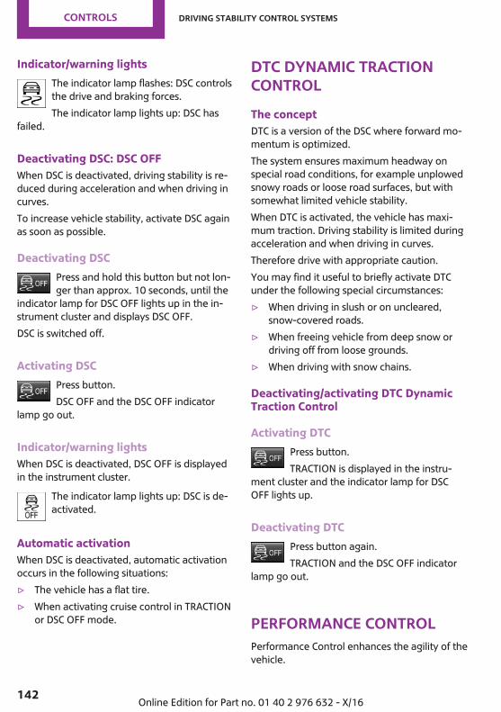
Indicator/warning lightsThe indicator lamp flashes: DSC controlsthe drive and braking forces.The indicator lamp lights up: DSC has
failed.
Deactivating DSC: DSC OFFWhen DSC is deactivated, driving stability is re‐duced during acceleration and when driving incurves.To increase vehicle stability, activate DSC againas soon as possible.
Deactivating DSCPress and hold this button but not lon‐ger than approx. 10 seconds, until the
indicator lamp for DSC OFF lights up in the in‐strument cluster and displays DSC OFF.DSC is switched off.
Activating DSCPress button.DSC OFF and the DSC OFF indicator
lamp go out.
Indicator/warning lightsWhen DSC is deactivated, DSC OFF is displayedin the instrument cluster.
The indicator lamp lights up: DSC is de‐activated.
Automatic activationWhen DSC is deactivated, automatic activationoccurs in the following situations:▷ The vehicle has a flat tire.▷ When activating cruise control in TRACTION
or DSC OFF mode.
DTC Dynamic TractionControlThe conceptDTC is a version of the DSC where forward mo‐mentum is optimized.The system ensures maximum headway onspecial road conditions, for example unplowedsnowy roads or loose road surfaces, but withsomewhat limited vehicle stability.When DTC is activated, the vehicle has maxi‐mum traction. Driving stability is limited duringacceleration and when driving in curves.Therefore drive with appropriate caution.You may find it useful to briefly activate DTCunder the following special circumstances:▷ When driving in slush or on uncleared,
snow-covered roads.▷ When freeing vehicle from deep snow or
driving off from loose grounds.▷ When driving with snow chains.
Deactivating/activating DTC DynamicTraction Control
Activating DTCPress button.TRACTION is displayed in the instru‐
ment cluster and the indicator lamp for DSCOFF lights up.
Deactivating DTCPress button again.TRACTION and the DSC OFF indicator
lamp go out.
Performance ControlPerformance Control enhances the agility of thevehicle.
Seite 142
CONTROLS Driving stability control systems
142 Online Edition for Part no. 01 40 2 976 632 - X/16

To increase maneuverability, wheels are brakedindividually when a sporty driving style is used.
ALL4ALL4 is the all-wheel-drive system of your vehi‐cle. Concerted action by ALL4 and DSC furtheroptimize traction and driving dynamics. TheALL4 all-wheel-drive system variably distributesthe driving forces to the front and rear axles asdemanded by the driving situation and roadsurface.
Dynamic Damping Con‐trolConceptThe tuning of the suspension can be changedwith the system.The system offers several different programs.The programs are selected via the MINI DrivingModes switch.
Programs
MID/GREENBalanced tuning of the shock absorbers formore comfort.
SPORTConsistently sporty tuning of the shock absorb‐ers for greater driving agility.
MINI Driving ModesswitchConceptThe MINI Driving Modes switch helps to fine-tune the vehicle's settings and features. Choosebetween three different programs. The MINI
Driving Modes switch will activate the particularprogram.
Operating the programs
MINI Driving Modes switch Program
MIDGREENSPORT
MIDFor balanced tuning.With each starting operation, MID is activatedusing the Start/Stop button.
GREEN
ConceptGREEN, refer to page 196, provides consistenttuning to maximize range.
Activating GREENTurn MINI Driving Modes switch to the right un‐til GREEN is displayed in the instrument cluster.
Configuring GREEN
Via MINI Driving Modes switch1. Activate GREEN.2. "Configure GREEN"3. Configure the program.This configuration is retrieved when GREEN isactivated.
Via the onboard monitor:1. "My MINI"2. "Vehicle settings"3. If necessary, "Driving mode"4. "Configure GREEN"5. Select the desired setting.
Seite 143
Driving stability control systems CONTROLS
143Online Edition for Part no. 01 40 2 976 632 - X/16
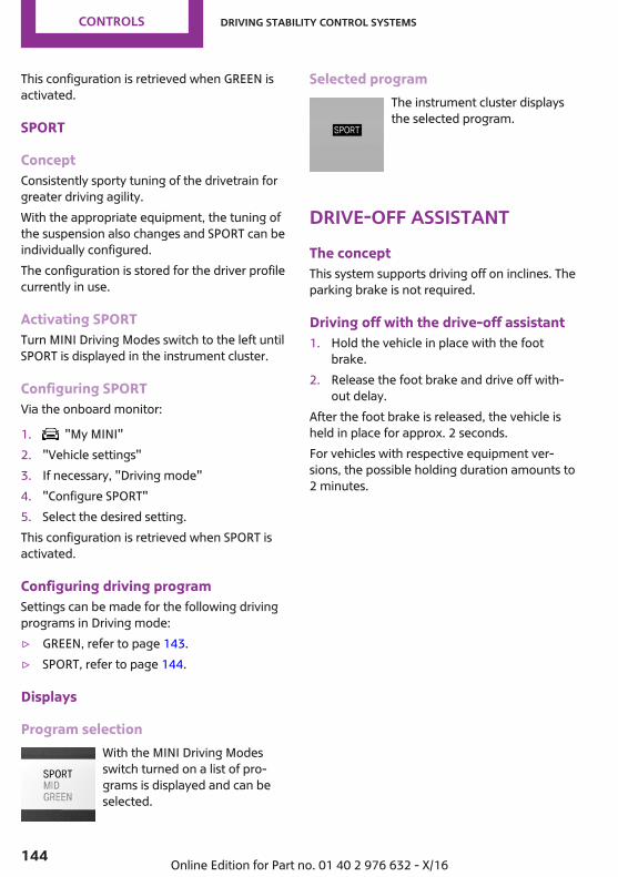
This configuration is retrieved when GREEN isactivated.
SPORT
ConceptConsistently sporty tuning of the drivetrain forgreater driving agility.With the appropriate equipment, the tuning ofthe suspension also changes and SPORT can beindividually configured.The configuration is stored for the driver profilecurrently in use.
Activating SPORTTurn MINI Driving Modes switch to the left untilSPORT is displayed in the instrument cluster.
Configuring SPORTVia the onboard monitor:
1. "My MINI"2. "Vehicle settings"3. If necessary, "Driving mode"4. "Configure SPORT"5. Select the desired setting.This configuration is retrieved when SPORT isactivated.
Configuring driving programSettings can be made for the following drivingprograms in Driving mode:▷ GREEN, refer to page 143.▷ SPORT, refer to page 144.
Displays
Program selectionWith the MINI Driving Modesswitch turned on a list of pro‐grams is displayed and can beselected.
Selected programThe instrument cluster displaysthe selected program.
Drive-off assistantThe conceptThis system supports driving off on inclines. Theparking brake is not required.
Driving off with the drive-off assistant1. Hold the vehicle in place with the foot
brake.2. Release the foot brake and drive off with‐
out delay.After the foot brake is released, the vehicle isheld in place for approx. 2 seconds.For vehicles with respective equipment ver‐sions, the possible holding duration amounts to2 minutes.
Seite 144
CONTROLS Driving stability control systems
144 Online Edition for Part no. 01 40 2 976 632 - X/16
Driving comfortVehicle features and op‐tionsThis chapter describes all standard, country-specific and optional features offered with theseries. It also describes features that are notnecessarily available in your vehicle, e. g., dueto the selected options or country versions. Thisalso applies to safety-related functions and sys‐tems. When using these functions and systems,the applicable laws and regulations must beobserved.
Camera-based cruise con‐trolConceptUsing this system, a desired speed and a dis‐tance to a vehicle ahead can be adjusted usingthe buttons on the steering wheel.The system maintains the desired speed onclear roads. For this purpose, the vehicle accel‐erates or brakes automatically.If a vehicle is driving ahead of you, the systemadjusts the speed of your vehicle within thegiven system limits so that the set distance tothe vehicle ahead is maintained.The distance can be adjusted in several steps.For safety reasons, it depends on the respectivespeed.With the Stop&Go function for Steptronic trans‐missions: if the vehicle ahead of you brakes to ahalt, and then proceeds to drive again shortlythereafter, the system is able to detect thiswithin the given system limits.
General informationA camera on the interior rear view mirror isused to detect vehicles driving ahead.
Depending on the driving settings, the featuresof the cruise control can change in certainareas.
Safety informationWARNINGThe system does not release from the
personal responsibility to correctly assess thetraffic situation. Based on the limits of the sys‐tem, it cannot independently react to all trafficsituations. There is a risk of an accident. Adjustthe driving style to the traffic conditions. Watchtraffic closely and actively intervene in the re‐spective situations.◀
WARNINGThe desired speed can be incorrectly ad‐
justed or called up by mistake. There is a risk ofan accident. Adjust the desired speed to thetraffic conditions. Watch traffic closely and ac‐tively intervene in the respective situations.◀
WARNINGRisk of accident due to too high speed
differences to other vehicles, e.g., in the follow‐ing situations:▷ When fast approaching a slowly moving ve‐
hicle.▷ Suddenly swerving vehicle onto the own
lane.▷ When fast approaching standing vehicles.There is a risk of injuries or danger to life.Watch traffic closely and actively intervene inthe respective situations.◀
WARNINGAn unsecured vehicle can begin to move
and possibly roll away. There is a risk of an acci‐dent. Before exiting, secure the vehicle againstrolling.
Seite 145
Driving comfort CONTROLS
145Online Edition for Part no. 01 40 2 976 632 - X/16

In order to ensure that the vehicle is securedagainst rolling away, observe the following:▷ Set the parking brake.▷ On uphill grades or on a downhill slope,
turn the front wheels in the direction of thecurb.
▷ On uphill grades or on a downhill slope,also secure the vehicle, e.g., with a wheelchock.◀
Overview
Buttons on the steering wheel
Press button Function
Cruise control on/off, refer topage 146.
Store/maintain speed, refer topage 147.
Pause cruise control, refer topage 146.Continue cruise control with thelast setting, refer to page 148.
Reduce distance, refer topage 148.
Increase distance, refer topage 148.
Increase speed, refer topage 147.
Reduce speed, refer to page 147.
Buttons are arranged according to vehicle's ser‐ies, optional features and country specifica‐tions.
Camera
The camera is installed near the interior rear‐view mirror.Keep the windshield in the area behind the in‐terior rearview mirror clean and clear.
Functional requirements
Speed rangeThe system is best used on well-constructedroads.The system is functional at speeds beginning atapprox. 20 mph/30 km/h.With the Stop&Go function for Steptronic trans‐missions: the system can also be activatedwhile the vehicle is stationary.The max. speed that can be set is85 mph/140 km/h.Manual transmission: Active Cruise Control is in‐terrupted below a speed of approx.20 mph/30 km/h. The system does not brake toa stop.
Switching on/off and interrupting cruisecontrol
Switching onPress button on the steering wheel.
Display in the instrument cluster lightsup.
Seite 146
CONTROLS Driving comfort
146 Online Edition for Part no. 01 40 2 976 632 - X/16
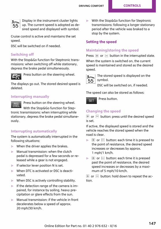
Display in the instrument cluster lightsup. The current speed is adopted as de‐sired speed and displayed with symbol.
Cruise control is active and maintains the setspeed.DSC will be switched on if needed.
Switching offWith the Stop&Go function for Steptronic trans‐missions: when switching off while stationary,depress the brake pedal simultaneously.
Press button on the steering wheel.
The displays go out. The stored desired speed isdeleted.
Interrupting manuallyPress button on the steering wheel.With the Stop&Go function for Step‐
tronic transmissions: when interrupting whilestationary, depress the brake pedal simultane‐ously.
Interrupting automaticallyThe system is automatically interrupted in thefollowing situations:▷ When the driver applies the brakes.▷ Manual transmission: when the clutch
pedal is depressed for a few seconds or re‐leased while a gear is not engaged.
▷ If selector lever position N is set.▷ When DTC is activated or DSC is deacti‐
vated.▷ When DSC is actively controlling stability.▷ If the detection range of the camera is im‐
paired, for instance by soiling, heavy pre‐cipitation or glare effects from the sun.
▷ Manual transmission: if the vehicle in frontdecelerates below a speed of approx.20 mph/30 km/h.
▷ With the Stop&Go function for Steptronictransmissions: following a longer stationaryperiod after the vehicle was braked to astop by the system.
Setting the speed
Maintaining/storing the speedPress or button in the interrupted state.When the system is switched on, the currentspeed is maintained and stored as the desiredspeed.
The stored speed is displayed on thesymbol.DSC will be switched on, if needed.
The speed can also be stored as follows:Press button.
Changing the speed or button: press until the desired speed
is set.If active, the displayed speed is stored and thevehicle reaches the stored speed when theroad is clear.▷ or button: each time it is pressed to
the point of resistance, the desired speedincreases or decreases by approx.1 mph/1 km/h.
▷ or button: each time it is pressedpast the point of resistance, the desiredspeed increases or decreases by a maxi‐mum of 5 mph/10 km/h.
or button: hold down to repeat the ac‐tion.
Seite 147
Driving comfort CONTROLS
147Online Edition for Part no. 01 40 2 976 632 - X/16
Adjusting distance
Safety informationWARNINGThe system does not release from the
personal responsibility. Due to the system lim‐its, braking can be late. There is a risk of acci‐dents or risk of property damage. Be aware tothe traffic situation at all times. Adjust the dis‐tance to the traffic and weather conditions andmaintain the prescribed safety distance, possi‐bly by braking.◀
Reduce distancePress button repeatedly until the de‐sired distance is set.
The set distance is briefly displayed inthe left part of the instrument cluster.
Increase distancePress button repeatedly until the de‐sired distance is set.
The set distance is briefly displayed inthe left part of the instrument cluster.
Continuing cruise control
General informationAn interrupted cruise control can be continuedby calling up the stored speed.Make sure that the difference between currentspeed and stored speed is not too large beforecalling up the stored speed. Otherwise, unin‐tentional braking or accelerating may occur.In the following cases, the stored speed value isdeleted and cannot be called up again:▷ When the system is switched off.▷ When the ignition is switched off.
Calling up stored speed and distancePress button with the system inter‐rupted. Cruise control is continued with
the saved values. The selected distance isbriefly displayed in the CID (central informationdisplay).
Switching distance control on/off
Safety informationWARNINGThe system does not react to traffic driv‐
ing ahead of you, but instead maintains thestored speed. There is a risk of accidents or riskof property damage. Adjust the desired speedto the traffic conditions and brake as needed.◀
Switching distance control offPress and hold this button.
Or:Press and hold this button.
The indicator lamp in the instrumentcluster lights up.
To switch distance control back on, press one ofthe two buttons again briefly.After changing over distance control, a CheckControl message is displayed.
Displays in the instrument cluster
Desired speed and stored speedIn addition to the indicator lamp, thedesired speed is displayed in the centralinformation display.
▷ Display lights up green: system is active, thedisplay indicates the desired speed.
Seite 148
CONTROLS Driving comfort
148 Online Edition for Part no. 01 40 2 976 632 - X/16

▷ Display lights up orange: system is inter‐rupted, the display indicates the storedspeed.
▷ No display: system is switched off.If no speed is indicated, it is possible that theconditions necessary for operation are not cur‐rently fulfilled.
Distance to vehicle ahead of youSelected distance from the vehicle drivingahead is briefly displayed in the left hand por‐tion of the CID (central information display).Distance display
Distance 1
Distance 2
Distance 3
Distance 4This value is set automatically afterthe system is switched on.
Detected vehicleSymbol lights up orange:A vehicle has been detected ahead ofyou.
With the Stop&Go function for Step‐tronic transmissions:Rolling bars: the detected vehicle has
driven away.ACC does not accelerate. To accelerate, activateACC by briefly stepping on the acceleratorpedal or by pressing the RES CNCL button orthe or button.
Indicator/warning lightsSymbol flashes orange:The conditions are not adequate for thesystem to work.
The system was deactivated but applies thebrakes until you actively resume control bypressing on the brake pedal or acceleratorpedal.
Symbol flashes red and a signal sounds:You are requested to intervene by brak‐ing or make an evasive maneuver.
The system has been interrupted or dis‐tance control is temporarily suppressedbecause the accelerator pedal is being
pressed; a vehicle was not detected.
Distance control is temporarily sup‐pressed because the accelerator pedalis being pressed; a vehicle was de‐
tected.
Displays in the Head-up DisplayThe information from Active Cruise Control canalso be displayed in the Head-up Display.
System limits
Detection range
The detection capacity of the system and theautomatic braking capacity are limited.Two-wheeled vehicles for instance might notbe detected.
Seite 149
Driving comfort CONTROLS
149Online Edition for Part no. 01 40 2 976 632 - X/16
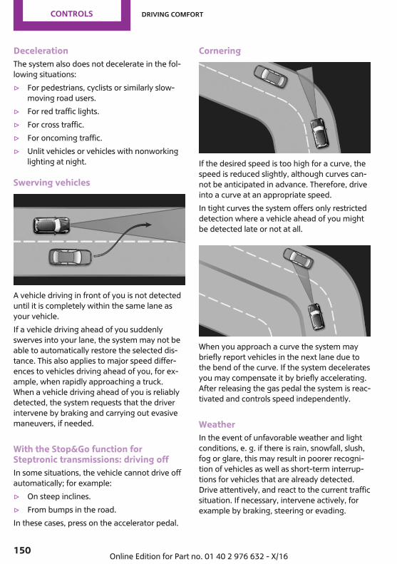
DecelerationThe system also does not decelerate in the fol‐lowing situations:▷ For pedestrians, cyclists or similarly slow-
moving road users.▷ For red traffic lights.▷ For cross traffic.▷ For oncoming traffic.▷ Unlit vehicles or vehicles with nonworking
lighting at night.
Swerving vehicles
A vehicle driving in front of you is not detecteduntil it is completely within the same lane asyour vehicle.If a vehicle driving ahead of you suddenlyswerves into your lane, the system may not beable to automatically restore the selected dis‐tance. This also applies to major speed differ‐ences to vehicles driving ahead of you, for ex‐ample, when rapidly approaching a truck.When a vehicle driving ahead of you is reliablydetected, the system requests that the driverintervene by braking and carrying out evasivemaneuvers, if needed.
With the Stop&Go function forSteptronic transmissions: driving offIn some situations, the vehicle cannot drive offautomatically; for example:▷ On steep inclines.▷ From bumps in the road.In these cases, press on the accelerator pedal.
Cornering
If the desired speed is too high for a curve, thespeed is reduced slightly, although curves can‐not be anticipated in advance. Therefore, driveinto a curve at an appropriate speed.In tight curves the system offers only restricteddetection where a vehicle ahead of you mightbe detected late or not at all.
When you approach a curve the system maybriefly report vehicles in the next lane due tothe bend of the curve. If the system deceleratesyou may compensate it by briefly accelerating.After releasing the gas pedal the system is reac‐tivated and controls speed independently.
WeatherIn the event of unfavorable weather and lightconditions, e. g. if there is rain, snowfall, slush,fog or glare, this may result in poorer recogni‐tion of vehicles as well as short-term interrup‐tions for vehicles that are already detected.Drive attentively, and react to the current trafficsituation. If necessary, intervene actively, forexample by braking, steering or evading.
Seite 150
CONTROLS Driving comfort
150 Online Edition for Part no. 01 40 2 976 632 - X/16
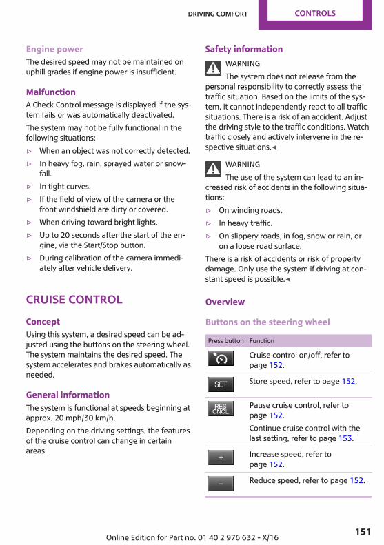
Engine powerThe desired speed may not be maintained onuphill grades if engine power is insufficient.
MalfunctionA Check Control message is displayed if the sys‐tem fails or was automatically deactivated.The system may not be fully functional in thefollowing situations:▷ When an object was not correctly detected.▷ In heavy fog, rain, sprayed water or snow‐
fall.▷ In tight curves.▷ If the field of view of the camera or the
front windshield are dirty or covered.▷ When driving toward bright lights.▷ Up to 20 seconds after the start of the en‐
gine, via the Start/Stop button.▷ During calibration of the camera immedi‐
ately after vehicle delivery.
Cruise controlConceptUsing this system, a desired speed can be ad‐justed using the buttons on the steering wheel.The system maintains the desired speed. Thesystem accelerates and brakes automatically asneeded.
General informationThe system is functional at speeds beginning atapprox. 20 mph/30 km/h.Depending on the driving settings, the featuresof the cruise control can change in certainareas.
Safety informationWARNINGThe system does not release from the
personal responsibility to correctly assess thetraffic situation. Based on the limits of the sys‐tem, it cannot independently react to all trafficsituations. There is a risk of an accident. Adjustthe driving style to the traffic conditions. Watchtraffic closely and actively intervene in the re‐spective situations.◀
WARNINGThe use of the system can lead to an in‐
creased risk of accidents in the following situa‐tions:▷ On winding roads.▷ In heavy traffic.▷ On slippery roads, in fog, snow or rain, or
on a loose road surface.There is a risk of accidents or risk of propertydamage. Only use the system if driving at con‐stant speed is possible.◀
Overview
Buttons on the steering wheel
Press button Function
Cruise control on/off, refer topage 152.
Store speed, refer to page 152.
Pause cruise control, refer topage 152.Continue cruise control with thelast setting, refer to page 153.
Increase speed, refer topage 152.
Reduce speed, refer to page 152.
Seite 151
Driving comfort CONTROLS
151Online Edition for Part no. 01 40 2 976 632 - X/16
Switching on/off and interrupting cruisecontrol
Switching onPress button on the steering wheel.
The indicator lamp in the instrumentcluster lights up.
The current speed is adopted as the de‐sired speed and is displayed with thesymbol in the instrument cluster.
Cruise control is active and maintains the setspeed.DSC will be switched on if needed.
Switching offPress button on the steering wheel.
The displays go out. The stored desired speed isdeleted.
Interrupting manuallyWhen active, press the button on thesteering wheel.
Automatic interruptionThe system is automatically interrupted in thefollowing situations:▷ When the driver applies the brakes.▷ If the clutch pedal is depressed for a few
seconds or released while a gear is not en‐gaged.
▷ If the gear engaged is too high for the cur‐rent speed.
▷ If selector lever position N is set.▷ When DTC is activated or DSC is deacti‐
vated.▷ When DSC is actively controlling stability.
Setting the speed
Maintaining/storing the speedPress or button in the interrupted state.When the system is switched on, the currentspeed is maintained and stored as the desiredspeed.The stored speed is displayed in the instrumentcluster.DSC will be switched on, if needed.The speed can also be stored as follows:
Press button.
Changing the speed or button: press until the desired speed
is set.If active, the displayed speed is stored and thevehicle reaches the stored speed when theroad is clear.▷ or button: each time it is pressed to
the point of resistance, the desired speedincreases or decreases by approx.1 mph/1 km/h.
▷ or button: each time it is pressedpast the point of resistance, the desiredspeed increases or decreases by a maxi‐mum of 5 mph/10 km/h.The maximum speed that can be set de‐pends on the vehicle.
▷ or button: pressing it to the resist‐ance point and holding it accelerates or de‐celerates the vehicle without requiringpressure on the accelerator pedal. After thebutton is released, the vehicle maintains itsfinal speed. Pressing the switch beyond theresistance point causes the vehicle to accel‐erate more rapidly.
Seite 152
CONTROLS Driving comfort
152 Online Edition for Part no. 01 40 2 976 632 - X/16

Continuing cruise control
General informationAn interrupted cruise control can be continuedby calling up the stored speed.Make sure that the difference between currentspeed and stored speed is not too large beforecalling up the stored speed. Otherwise, unin‐tentional braking or accelerating may occur.
Calling up stored speedPress button on the steering wheel.
The stored speed is reached and maintained.
Displays in the instrument cluster
Indicator lampDepending on how the vehicle is equip‐ped, the indicator lamp in the instru‐ment cluster indicates whether the sys‐
tem is switched on.
Desired speed and stored speedThe desired speed is displayed togetherwith the symbol.▷ Display lights up green: system is
active, the display indicates the de‐sired speed.
▷ Display lights up orange: system is inter‐rupted, the display indicates the storedspeed.
▷ No display: system is switched off.If no speed is indicated, it is possible that theconditions necessary for operation are not cur‐rently fulfilled.
System limits
Engine powerThe desired speed is also maintained downhill,but may not be maintained on uphill grades ifengine power is insufficient.
PDC Park Distance Con‐trolConceptPDC is a support when parking. When youslowly approach an object in the rear - or alsoin the front of the vehicle if the feature is avail‐able - then the object is reported through:▷ Signal tones.▷ Visual display.
General informationThe ultrasound sensors for measuring the dis‐tances are located in the bumpers.The maneuvering range, depending on obsta‐cles and environmental conditions, is approx.6 ft/2 m.An acoustic warning is first given in the follow‐ing situations:▷ By the front middle sensors and the two
corner sensors at approx. 24 in/60 cm fromthe object.
▷ By the rear middle sensors at ap‐prox. 5 ft/1.50 m from the object.
▷ When a collision is imminent.
Safety informationWARNINGThe system does not relieve from the per‐
sonal responsibility to correctly assess the traf‐fic situation. There is a risk of an accident. Ad‐just the driving style to the traffic conditions.Watch traffic and vehicle surroundings closely
Seite 153
Driving comfort CONTROLS
153Online Edition for Part no. 01 40 2 976 632 - X/16
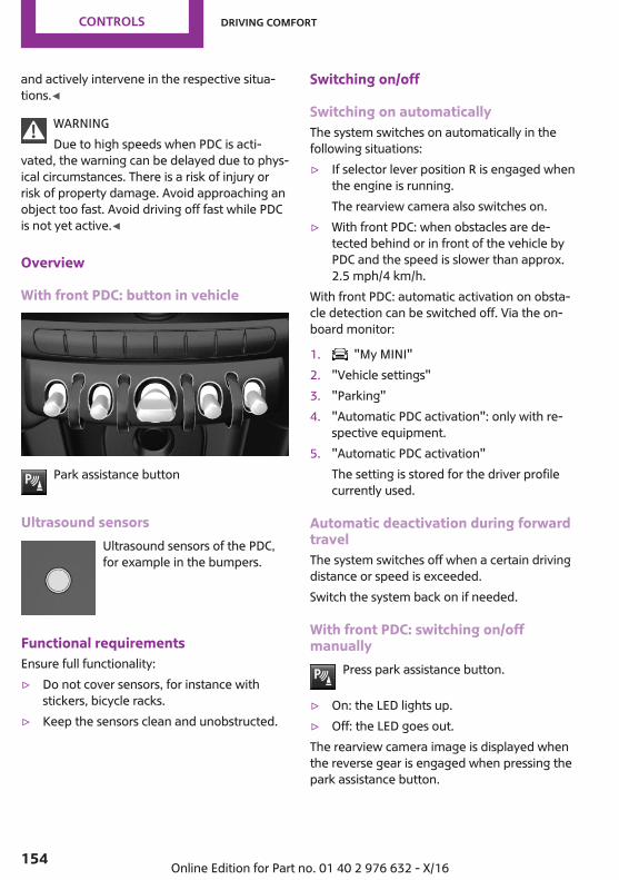
and actively intervene in the respective situa‐tions.◀
WARNINGDue to high speeds when PDC is acti‐
vated, the warning can be delayed due to phys‐ical circumstances. There is a risk of injury orrisk of property damage. Avoid approaching anobject too fast. Avoid driving off fast while PDCis not yet active.◀
Overview
With front PDC: button in vehicle
Park assistance button
Ultrasound sensorsUltrasound sensors of the PDC,for example in the bumpers.
Functional requirementsEnsure full functionality:▷ Do not cover sensors, for instance with
stickers, bicycle racks.▷ Keep the sensors clean and unobstructed.
Switching on/off
Switching on automaticallyThe system switches on automatically in thefollowing situations:▷ If selector lever position R is engaged when
the engine is running.The rearview camera also switches on.
▷ With front PDC: when obstacles are de‐tected behind or in front of the vehicle byPDC and the speed is slower than approx.2.5 mph/4 km/h.
With front PDC: automatic activation on obsta‐cle detection can be switched off. Via the on‐board monitor:
1. "My MINI"2. "Vehicle settings"3. "Parking"4. "Automatic PDC activation": only with re‐
spective equipment.5. "Automatic PDC activation"
The setting is stored for the driver profilecurrently used.
Automatic deactivation during forwardtravelThe system switches off when a certain drivingdistance or speed is exceeded.Switch the system back on if needed.
With front PDC: switching on/offmanually
Press park assistance button.
▷ On: the LED lights up.▷ Off: the LED goes out.The rearview camera image is displayed whenthe reverse gear is engaged when pressing thepark assistance button.
Seite 154
CONTROLS Driving comfort
154 Online Edition for Part no. 01 40 2 976 632 - X/16
WARNING
Signal tonesWhen approaching an object, an intermittentsound indicates the position of the object. E.g.,if an object is detected to the left rear of the ve‐hicle, a signal tone sounds from the left rearspeaker.The shorter the distance to the object, theshorter the intervals.If the distance to a detected object is less thanapprox. 10 inches/25 cm, a continuous tone issounded.With front PDC: if objects are simultaneously lo‐cated both in front of and behind the vehicle,an alternating continuous signal is sounded.The signal tone is switched off, when selectorlever position P is engaged on vehicles withSteptronic transmission.
VolumeThe ratio of the PDC signal tone volume to theentertainment volume can be adjusted.Via the onboard monitor:
1. "My MINI"2. "System settings"3. "Tone"4. "Volume settings"5. "PDC"6. Set the desired value.The setting is stored for the driver profile cur‐rently used.
Visual warningThe approach of the vehicle to an object can beshown on the Control Display. Objects that arefarther away are already displayed on the Con‐trol Display before a signal sounds.A display appears as soon as Park DistanceControl (PDC) is activated.
The range of the sensors is represented in col‐ors: red, green and yellow.When the image of the rearview camera is dis‐played, the switch can be made to PDC:
"Rear view camera"
System limits
Safety informationWARNINGThe system can react incorrectly or not at
all due to the system limits. There is a risk of ac‐cidents or risk of property damage. Observe theinformation regarding the system limits and ac‐tively intervene, if needed.◀
Limits of ultrasonic measurementUltrasonic measuring might not function underthe following circumstances:▷ For small children and animals.▷ For persons with certain clothing, for in‐
stance coats.▷ With external interference of the ultra‐
sound, for instance from passing vehicles orloud machines.
▷ When sensors are dirty, iced over, damagedor out of position.
▷ If cargo protrudes.▷ Under certain weather conditions such as
high relative humidity, rain, snowfall, ex‐treme heat or strong wind.
▷ With tow bars and trailer couplings of othervehicles.
▷ With thin or wedge-shaped objects.▷ With moving objects.▷ With elevated, protruding objects such as
ledges or cargo.▷ With objects with corners and sharp edges.▷ With objects with a fine surface structure
such as fences.▷ For objects with porous surfaces.
Seite 155
Driving comfort CONTROLS
155Online Edition for Part no. 01 40 2 976 632 - X/16
▷ Low objects already displayed, for instancecurbs, can move into the blind area of thesensors before or after a continuous tonesounds.
False warningsThe system may issue a warning under the fol‐lowing conditions even though there is no ob‐stacle within the detection range:▷ In heavy rain.▷ When sensors are very dirty or covered with
ice.▷ When sensors are covered in snow.▷ On rough road surfaces.▷ On uneven surfaces, such as speed bumps.▷ In large buildings with right angles and
smooth walls, for instance in undergroundgarages.
▷ In automatic vehicle washes.▷ Due to heavy exhaust.▷ Due to other ultrasound sources, for in‐
stance sweeping machines, high pressuresteam cleaners or neon lights.The malfunction is signaled by a continuoustone alternating between the front and rearspeakers. As soon as the malfunction dueto other ultrasound sources is no longerpresent, the system is again fully functional.
With front PDC: to reduce false alarms, switchoff automatic PDC activation on obstacle detec‐tion, for instance in vehicle washes; see Switch‐ing on/off.
MalfunctionA Check Control message is displayed in the in‐strument cluster.
Red symbol is displayed, and the rangeof the sensors is dimmed on the ControlDisplay.
PDC has failed. Have the system checked by adealer’s service center or another qualifiedservice center or repair shop.
Rearview cameraConceptThe rearview camera provides assistance inparking and maneuvering backwards. The areabehind the vehicle is shown on the Control Dis‐play.
Safety informationWARNINGThe system does not relieve from the per‐
sonal responsibility to correctly assess the traf‐fic situation. There is a risk of an accident. Ad‐just the driving style to the traffic conditions.Watch traffic and vehicle surroundings closelyand actively intervene in the respective situa‐tions.◀
Overview
Button in the vehicle
Park assistance button
Seite 156
CONTROLS Driving comfort
156 Online Edition for Part no. 01 40 2 976 632 - X/16
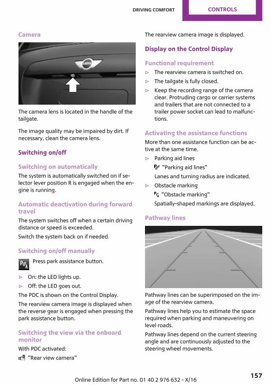
Camera
The camera lens is located in the handle of thetailgate.
The image quality may be impaired by dirt. Ifnecessary, clean the camera lens.
Switching on/off
Switching on automaticallyThe system is automatically switched on if se‐lector lever position R is engaged when the en‐gine is running.
Automatic deactivation during forwardtravelThe system switches off when a certain drivingdistance or speed is exceeded.Switch the system back on if needed.
Switching on/off manuallyPress park assistance button.
▷ On: the LED lights up.▷ Off: the LED goes out.The PDC is shown on the Control Display.The rearview camera image is displayed whenthe reverse gear is engaged when pressing thepark assistance button.
Switching the view via the onboardmonitorWith PDC activated:
"Rear view camera"
The rearview camera image is displayed.
Display on the Control Display
Functional requirement▷ The rearview camera is switched on.▷ The tailgate is fully closed.▷ Keep the recording range of the camera
clear. Protruding cargo or carrier systemsand trailers that are not connected to atrailer power socket can lead to malfunc‐tions.
Activating the assistance functionsMore than one assistance function can be ac‐tive at the same time.▷ Parking aid lines
"Parking aid lines"Lanes and turning radius are indicated.
▷ Obstacle marking "Obstacle marking"
Spatially-shaped markings are displayed.
Pathway lines
Pathway lines can be superimposed on the im‐age of the rearview camera.Pathway lines help you to estimate the spacerequired when parking and maneuvering onlevel roads.Pathway lines depend on the current steeringangle and are continuously adjusted to thesteering wheel movements.
Seite 157
Driving comfort CONTROLS
157Online Edition for Part no. 01 40 2 976 632 - X/16

Turning circle lines
Turning circle lines can be superimposed on theimage of the rearview camera.Turning circle lines show the course of thesmallest possible turning radius on a level road.Only one turning radius line is displayed afterthe steering wheel is turned past a certain an‐gle.
Obstacle marking
Obstacle markings can be faded into the imageof the rearview camera.Their colored margins of the obstacle markingsmatch the markings of the PDC.
Parking using pathway and turningradius lines1. Position the vehicle so that the turning ra‐
dius lines lead to within the limits of theparking space.
2. Turn the steering wheel to the point wherethe pathway line covers the correspondingturning radius line.
Display settings
BrightnessWith the rearview camera switched on:
1. Select the symbol.2. Turn the Controller until the desired setting
is reached and press the Controller.
ContrastWith the rearview camera switched on:
1. Select the symbol.2. Turn the Controller until the desired setting
is reached and press the Controller.
Seite 158
CONTROLS Driving comfort
158 Online Edition for Part no. 01 40 2 976 632 - X/16

System limits
Detection of objectsVery low obstacles or high, protruding objectssuch as ledges may not be recognized by thesystem.Assistance functions also take into account dataof the PDC.Follow instructions in the PDC chapter.The objects displayed on the Control Displaymay be closer than they appear. Therefore, donot estimate the distance from the objects onthe display.
Parking assistantConcept
This system assists the driver in parking parallelto the road.
General informationParking assistant handling is divided into threesteps:▷ Switching on and activating.▷ Parking space search.▷ Parking.Ultrasound sensors measure parking spaces onboth sides of the vehicle.The parking assistant calculates the best possi‐ble parking line and takes control of steeringduring the parking procedure.
System status and instructions on required ac‐tions are displayed on the Control Display.A component of the parking assistant is thePDC Park Distance Control.
Safety informationWARNINGThe system does not release from the
personal responsibility to correctly assess thetraffic situation. Based on the limits of the sys‐tem, it cannot independently react to all trafficsituations. There is a risk of an accident. Adjustthe driving style to the traffic conditions. Watchtraffic closely and actively intervene in the re‐spective situations.◀
NOTEThe parking assistant can steer the vehi‐
cle over or onto curbs. There is a risk of prop‐erty damage. Watch traffic closely and activelyintervene in the respective situations.◀
The safety information of the PDC Park Dis‐tance Control applies in addition.
Overview
Button in the vehicle
Park assistance button
Seite 159
Driving comfort CONTROLS
159Online Edition for Part no. 01 40 2 976 632 - X/16
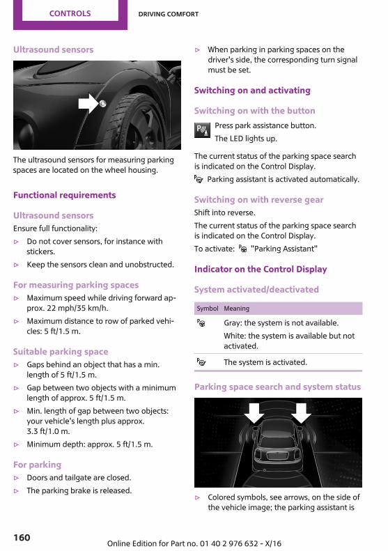
Ultrasound sensors
The ultrasound sensors for measuring parkingspaces are located on the wheel housing.
Functional requirements
Ultrasound sensorsEnsure full functionality:▷ Do not cover sensors, for instance with
stickers.▷ Keep the sensors clean and unobstructed.
For measuring parking spaces▷ Maximum speed while driving forward ap‐
prox. 22 mph/35 km/h.▷ Maximum distance to row of parked vehi‐
cles: 5 ft/1.5 m.
Suitable parking space▷ Gaps behind an object that has a min.
length of 5 ft/1.5 m.▷ Gap between two objects with a minimum
length of approx. 5 ft/1.5 m.▷ Min. length of gap between two objects:
your vehicle's length plus approx.3.3 ft/1.0 m.
▷ Minimum depth: approx. 5 ft/1.5 m.
For parking▷ Doors and tailgate are closed.▷ The parking brake is released.
▷ When parking in parking spaces on thedriver's side, the corresponding turn signalmust be set.
Switching on and activating
Switching on with the buttonPress park assistance button.The LED lights up.
The current status of the parking space searchis indicated on the Control Display.
Parking assistant is activated automatically.
Switching on with reverse gearShift into reverse.The current status of the parking space searchis indicated on the Control Display.To activate: "Parking Assistant"
Indicator on the Control Display
System activated/deactivated
Symbol Meaning
Gray: the system is not available.White: the system is available but notactivated.
The system is activated.
Parking space search and system status
▷ Colored symbols, see arrows, on the side ofthe vehicle image; the parking assistant is
Seite 160
CONTROLS Driving comfort
160 Online Edition for Part no. 01 40 2 976 632 - X/16
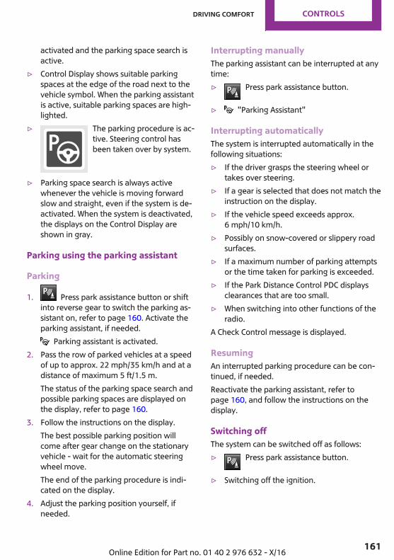
activated and the parking space search isactive.
▷ Control Display shows suitable parkingspaces at the edge of the road next to thevehicle symbol. When the parking assistantis active, suitable parking spaces are high‐lighted.
▷ The parking procedure is ac‐tive. Steering control hasbeen taken over by system.
▷ Parking space search is always activewhenever the vehicle is moving forwardslow and straight, even if the system is de‐activated. When the system is deactivated,the displays on the Control Display areshown in gray.
Parking using the parking assistant
Parking
1. Press park assistance button or shiftinto reverse gear to switch the parking as‐sistant on, refer to page 160. Activate theparking assistant, if needed.
Parking assistant is activated.2. Pass the row of parked vehicles at a speed
of up to approx. 22 mph/35 km/h and at adistance of maximum 5 ft/1.5 m.The status of the parking space search andpossible parking spaces are displayed onthe display, refer to page 160.
3. Follow the instructions on the display.The best possible parking position willcome after gear change on the stationaryvehicle - wait for the automatic steeringwheel move.The end of the parking procedure is indi‐cated on the display.
4. Adjust the parking position yourself, ifneeded.
Interrupting manuallyThe parking assistant can be interrupted at anytime:▷ Press park assistance button.
▷ "Parking Assistant"
Interrupting automaticallyThe system is interrupted automatically in thefollowing situations:▷ If the driver grasps the steering wheel or
takes over steering.▷ If a gear is selected that does not match the
instruction on the display.▷ If the vehicle speed exceeds approx.
6 mph/10 km/h.▷ Possibly on snow-covered or slippery road
surfaces.▷ If a maximum number of parking attempts
or the time taken for parking is exceeded.▷ If the Park Distance Control PDC displays
clearances that are too small.▷ When switching into other functions of the
radio.A Check Control message is displayed.
ResumingAn interrupted parking procedure can be con‐tinued, if needed.Reactivate the parking assistant, refer topage 160, and follow the instructions on thedisplay.
Switching offThe system can be switched off as follows:▷ Press park assistance button.
▷ Switching off the ignition.
Seite 161
Driving comfort CONTROLS
161Online Edition for Part no. 01 40 2 976 632 - X/16
System limits
Safety informationWARNINGThe system can react incorrectly or not at
all due to the system limits. There is a risk of ac‐cidents or risk of property damage. Observe theinformation regarding the system limits and ac‐tively intervene, if needed.◀
No parking assistanceThe parking assistant does not offer assistancein the following situations:▷ In tight curves.
Functional limitationsThe system may not be fully functional in thefollowing situations:▷ On bumpy road surfaces such as gravel
roads.▷ On slippery ground.▷ With accumulations of leaves/snow in the
parking space.▷ With a mounted emergency wheel.▷ With ditches or edges, for instance an edge
of a port.
Limits of ultrasonic measurementUltrasonic measuring might not function underthe following circumstances:▷ For small children and animals.▷ For persons with certain clothing, e.g.,
coats.▷ With external interference of the ultra‐
sound, e.g., from passing vehicles or loudmachines.
▷ When sensors are dirty, iced over, damagedor out of position.
▷ If cargo protrudes.
▷ Under certain weather conditions such ashigh relative humidity, rain, snowfall, ex‐treme heat or strong wind.
▷ With tow bars and trailer couplings of othervehicles.
▷ With thin or wedge-shaped objects.▷ With moving objects.▷ With elevated, protruding objects such as
ledges or cargo.▷ With objects with corners and sharp edges.▷ With objects with a fine surface structure
such as fences.▷ For objects with porous surfaces.▷ Low objects already displayed, e.g., curbs,
can move into the blind area of the sensorsbefore or after a continuous tone sounds.
▷ The parking assistant may identify parkingspaces that are not suitable for parking.
Tire sizeThe parking position may vary depending onthe tire size.
MalfunctionA Check Control message is displayed.The parking assistant failed. Have the systemchecked by a dealer’s service center or anotherqualified service center or repair shop.
Seite 162
CONTROLS Driving comfort
162 Online Edition for Part no. 01 40 2 976 632 - X/16
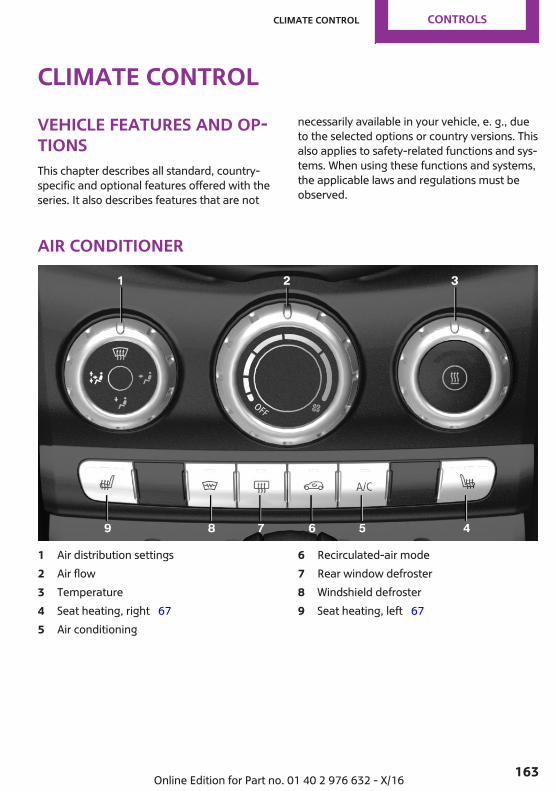
Climate controlVehicle features and op‐tionsThis chapter describes all standard, country-specific and optional features offered with theseries. It also describes features that are not
necessarily available in your vehicle, e. g., dueto the selected options or country versions. Thisalso applies to safety-related functions and sys‐tems. When using these functions and systems,the applicable laws and regulations must beobserved.
Air conditioner
1 Air distribution settings2 Air flow3 Temperature4 Seat heating, right 675 Air conditioning
6 Recirculated-air mode7 Rear window defroster8 Windshield defroster9 Seat heating, left 67
Seite 163
Climate control CONTROLS
163Online Edition for Part no. 01 40 2 976 632 - X/16

Climate control functions in detail
Switching the system on/off
Switching onSet any air volume.
Switching offTurn wheel for air quantity to theleft until the control switches off.
Temperature
ConceptThe system provides heat depending on thedesired temperature.
SettingsTurn the ring to set the desiredtemperature.
Air conditioning
ConceptThe air in the vehicle's interior will be cooledand dehumidified and, depending on the tem‐perature setting, warmed again.The vehicle's interior can only be cooled withthe engine running.
Switching on/offPress button.Air conditioning is switched on or off.
Depending on the weather, the windshield mayfog up briefly when the engine is started.
The air conditioner produces condensation wa‐ter, refer to page 192, that will exit from belowthe vehicle.
Recirculated-air mode
ConceptYou may react to unpleasant odors or pollu‐tants in the immediate environment by tempo‐rarily suspending the supply of outside air. Thesystem then recirculates the air flow within thevehicle.
OperationPress button repeatedly to select anoperating mode:
▷ LED off: outside air flows in continuously.▷ LED on, recirculated-air mode: the supply
of outside air into the vehicle is perma‐nently blocked.
To prevent window condensation, recirculated-air mode switches off automatically after a cer‐tain amount of time, depending on the externaltemperature.With constant recirculated-air mode, the airquality in the vehicle's interior deteriorates andthe fogging of the windows increases.If the windows fog over, switch off recirculated-air mode and increase the air flow, if needed.
Controlling the air flow manually
ConceptThe air flow for climate control can be adjustedmanually.
OperationTurn the ring to set the desiredair flow.The higher the air flow, the moreeffective the heating or coolingwill be.
Seite 164
CONTROLS Climate control
164 Online Edition for Part no. 01 40 2 976 632 - X/16
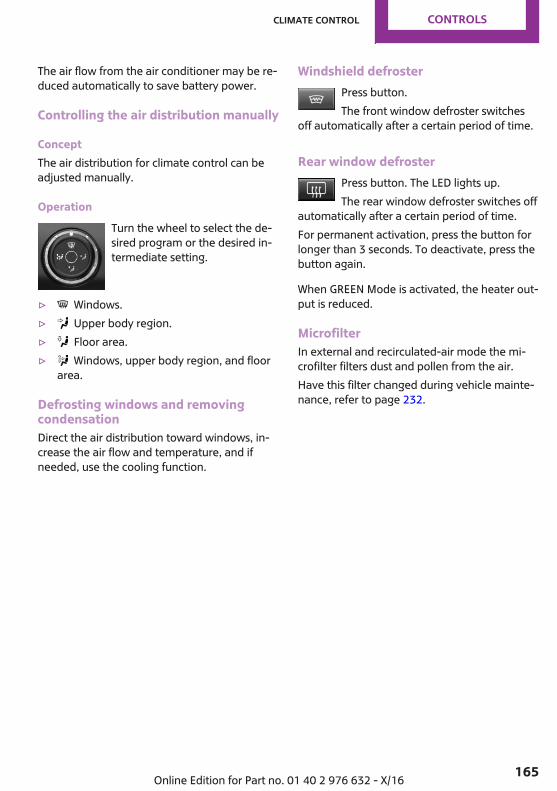
The air flow from the air conditioner may be re‐duced automatically to save battery power.
Controlling the air distribution manually
ConceptThe air distribution for climate control can beadjusted manually.
OperationTurn the wheel to select the de‐sired program or the desired in‐termediate setting.
▷ Windows.▷ Upper body region.▷ Floor area.▷ Windows, upper body region, and floor
area.
Defrosting windows and removingcondensationDirect the air distribution toward windows, in‐crease the air flow and temperature, and ifneeded, use the cooling function.
Windshield defrosterPress button.The front window defroster switches
off automatically after a certain period of time.
Rear window defrosterPress button. The LED lights up.The rear window defroster switches off
automatically after a certain period of time.For permanent activation, press the button forlonger than 3 seconds. To deactivate, press thebutton again.
When GREEN Mode is activated, the heater out‐put is reduced.
MicrofilterIn external and recirculated-air mode the mi‐crofilter filters dust and pollen from the air.Have this filter changed during vehicle mainte‐nance, refer to page 232.
Seite 165
Climate control CONTROLS
165Online Edition for Part no. 01 40 2 976 632 - X/16
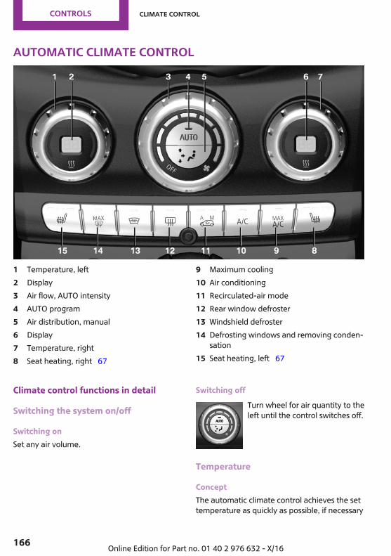
Automatic climate control
1 Temperature, left2 Display3 Air flow, AUTO intensity4 AUTO program5 Air distribution, manual6 Display7 Temperature, right8 Seat heating, right 67
9 Maximum cooling10 Air conditioning11 Recirculated-air mode12 Rear window defroster13 Windshield defroster14 Defrosting windows and removing conden‐
sation15 Seat heating, left 67
Climate control functions in detail
Switching the system on/off
Switching onSet any air volume.
Switching offTurn wheel for air quantity to theleft until the control switches off.
Temperature
ConceptThe automatic climate control achieves the settemperature as quickly as possible, if necessary
Seite 166
CONTROLS Climate control
166 Online Edition for Part no. 01 40 2 976 632 - X/16

by using the maximum cooling or heatingpower, and then keeps it constant.
SettingsTurn the ring to set the desiredtemperature.
The automatic climate control reaches thistemperature as quickly as possible, if needed,by increasing the cooling or heating output,and then keeps it constant.Do not rapidly switch between different tem‐perature settings. The automatic climate con‐trol will not have sufficient time to adjust theset temperature.
Air conditioning
ConceptThe air in the vehicle's interior will be cooledand dehumidified and, depending on the tem‐perature setting, warmed again.The vehicle's interior can only be cooled withthe engine running.
Switching on/offPress button.Air conditioning is switched on or off.
Depending on the weather, the windshield mayfog up briefly when the engine is started.The cooling function is switched on automati‐cally with the AUTO program.When using the automatic climate control, con‐densation water, refer to page 192, developsand drains underneath the vehicle. This is nor‐mal.
Maximum cooling
ConceptThe system is set to the lowest temperature,maximum air flow and recirculated-air mode.
General informationThe function is available with external tempera‐tures beyond approx. 32 ℉/0 ℃ and with theengine running.Air flows out of the vents to the upper body re‐gion. The vents need to be open for this.The air flow can be adjusted with the air flowactive.
Switching on/offPress button.The system is set to the lowest temper‐
ature, optimum air flow and air circulationmode.
AUTO program
ConceptAir flow, air distribution and temperature arecontrolled automatically.
Switching on/offPress button.
Depending on the selected temperature, AUTOintensity and outside influences, the air is di‐rected to the windshield, side windows, upperbody, and into the floor area.The following features are switched on auto‐matically with the AUTO program:▷ The cooling function, refer to page 167.To switch off the program: press the buttonagain or manually adjust the air distribution.
Seite 167
Climate control CONTROLS
167Online Edition for Part no. 01 40 2 976 632 - X/16
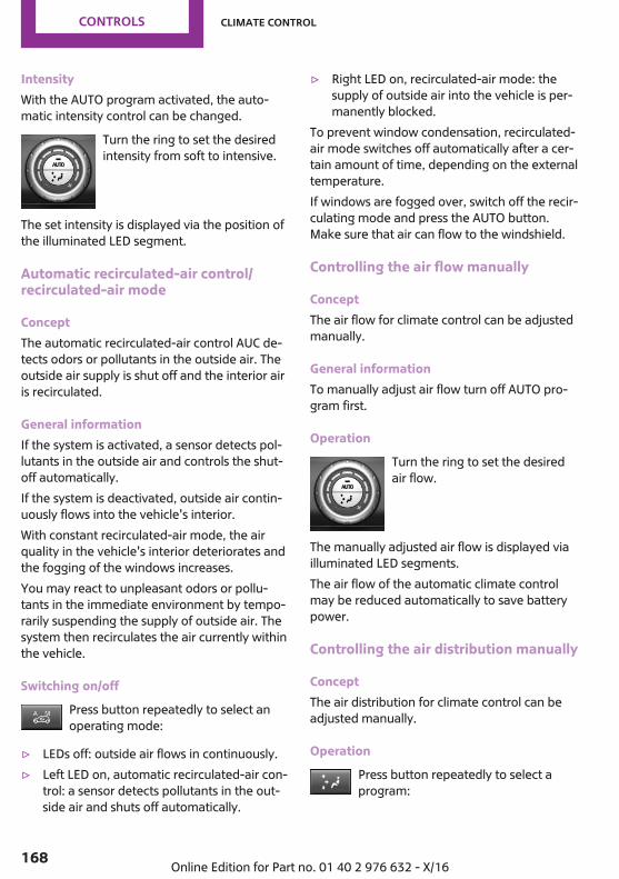
IntensityWith the AUTO program activated, the auto‐matic intensity control can be changed.
Turn the ring to set the desiredintensity from soft to intensive.
The set intensity is displayed via the position ofthe illuminated LED segment.
Automatic recirculated-air control/recirculated-air mode
ConceptThe automatic recirculated-air control AUC de‐tects odors or pollutants in the outside air. Theoutside air supply is shut off and the interior airis recirculated.
General informationIf the system is activated, a sensor detects pol‐lutants in the outside air and controls the shut-off automatically.If the system is deactivated, outside air contin‐uously flows into the vehicle's interior.With constant recirculated-air mode, the airquality in the vehicle's interior deteriorates andthe fogging of the windows increases.You may react to unpleasant odors or pollu‐tants in the immediate environment by tempo‐rarily suspending the supply of outside air. Thesystem then recirculates the air currently withinthe vehicle.
Switching on/offPress button repeatedly to select anoperating mode:
▷ LEDs off: outside air flows in continuously.▷ Left LED on, automatic recirculated-air con‐
trol: a sensor detects pollutants in the out‐side air and shuts off automatically.
▷ Right LED on, recirculated-air mode: thesupply of outside air into the vehicle is per‐manently blocked.
To prevent window condensation, recirculated-air mode switches off automatically after a cer‐tain amount of time, depending on the externaltemperature.If windows are fogged over, switch off the recir‐culating mode and press the AUTO button.Make sure that air can flow to the windshield.
Controlling the air flow manually
ConceptThe air flow for climate control can be adjustedmanually.
General informationTo manually adjust air flow turn off AUTO pro‐gram first.
OperationTurn the ring to set the desiredair flow.
The manually adjusted air flow is displayed viailluminated LED segments.The air flow of the automatic climate controlmay be reduced automatically to save batterypower.
Controlling the air distribution manually
ConceptThe air distribution for climate control can beadjusted manually.
OperationPress button repeatedly to select aprogram:
Seite 168
CONTROLS Climate control
168 Online Edition for Part no. 01 40 2 976 632 - X/16
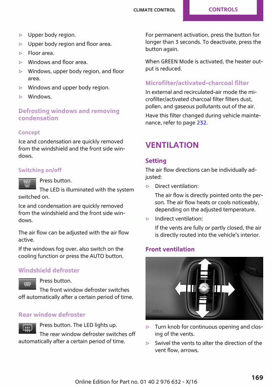
▷ Upper body region.▷ Upper body region and floor area.▷ Floor area.▷ Windows and floor area.▷ Windows, upper body region, and floor
area.▷ Windows and upper body region.▷ Windows.
Defrosting windows and removingcondensation
ConceptIce and condensation are quickly removedfrom the windshield and the front side win‐dows.
Switching on/offPress button.The LED is illuminated with the system
switched on.Ice and condensation are quickly removedfrom the windshield and the front side win‐dows.
The air flow can be adjusted with the air flowactive.If the windows fog over, also switch on thecooling function or press the AUTO button.
Windshield defrosterPress button.The front window defroster switches
off automatically after a certain period of time.
Rear window defrosterPress button. The LED lights up.The rear window defroster switches off
automatically after a certain period of time.
For permanent activation, press the button forlonger than 3 seconds. To deactivate, press thebutton again.
When GREEN Mode is activated, the heater out‐put is reduced.
Microfilter/activated-charcoal filterIn external and recirculated-air mode the mi‐crofilter/activated charcoal filter filters dust,pollen, and gaseous pollutants out of the air.Have this filter changed during vehicle mainte‐nance, refer to page 232.
VentilationSettingThe air flow directions can be individually ad‐justed:▷ Direct ventilation:
The air flow is directly pointed onto the per‐son. The air flow heats or cools noticeably,depending on the adjusted temperature.
▷ Indirect ventilation:If the vents are fully or partly closed, the airis directly routed into the vehicle's interior.
Front ventilation
▷ Turn knob for continuous opening and clos‐ing of the vents.
▷ Swivel the vents to alter the direction of thevent flow, arrows.
Seite 169
Climate control CONTROLS
169Online Edition for Part no. 01 40 2 976 632 - X/16

Ventilation in the rear
▷ Lever for changing the air flow direction,arrow 1.
▷ Thumbwheel for variable opening and clos‐ing of the vents, arrow 2.
Parked-vehicle ventila‐tionThe conceptThe parked-car ventilation ventilates the vehi‐cle interior and lowers its temperature, ifneeded.The system can be switched on and off at anyexternal temperature, either directly or by us‐ing two preset activation times. It remainsswitched on for 30 minutes.Open the vents to allow air to flow out.
Switching on/off directlyVia the onboard monitor:
1. "My MINI"2. "Vehicle settings"3. "Climate functions"4. "Activate comfort ventilation now"
The symbol on the automatic climate con‐trol flashes if the system is switched on.
Preselecting the activation timeVia the onboard monitor:
1. "My MINI"2. "Vehicle settings"3. If necessary, "Climate functions"4. "Comfort ventilation"5. Select the desired activation time.6. Set the desired time.
Activating the activation timeVia the onboard monitor:
1. "My MINI"2. "Vehicle settings"3. If necessary, "Climate functions"4. "For start time at:"
Activate the desired activation time. The symbol on the automatic climate con‐
trol lights up when the switch-on time is acti‐vated.
The symbol on the automatic climate con‐trol flashes when the system has been switchedon.The system will only be switched on within thenext 24 hours. After that, it needs to be reacti‐vated.
Seite 170
CONTROLS Climate control
170 Online Edition for Part no. 01 40 2 976 632 - X/16

Interior equipmentVehicle features and op‐tionsThis chapter describes all standard, country-specific and optional features offered with theseries. It also describes features that are notnecessarily available in your vehicle, e. g., dueto the selected options or country versions. Thisalso applies to safety-related functions and sys‐tems. When using these functions and systems,the applicable laws and regulations must beobserved.
Universal Integrated Re‐mote ControlConceptThe integrated Universal Remote Control in theinterior mirror can operate up to 3 functions ofremote-controlled systems, such as garagedoor drives or lighting systems. The UniversalIntegrated Remote Control replaces up to 3 dif‐ferent hand-held transmitters. To operate theremote control, the buttons on the interior mir‐ror must be programmed with the desiredfunctions. The hand-held transmitter for theparticular system is required in order to pro‐gram the remote control.Before selling the vehicle, delete the storedfunctions for the sake of security.
Safety informationWARNINGBody parts can be jammed when operat‐
ing remote-controlled systems, e.g., the garagedoor, using the integrated universal remotecontrol. There is a risk of injury or risk of prop‐erty damage. Make sure that the area of move‐ment of the respective system is clear during
programming and operation. Also follow thesafety instructions of the hand-held transmit‐ter.◀
CompatibilityIf this symbol is printed on the packag‐ing or in the owner's manual of the sys‐tem to be controlled, the system is gen‐
erally compatible with the Universal IntegratedRemote Control.If you have any questions, please contact:▷ A dealer’s service center or another quali‐
fied service center or repair shop.▷ www.homelink.com on the Internet.
HomeLink is a registered trademark of GentexCorporation.
Overview
1 LED2 Programmable keys3 Hand-held transmitters of the system
Programming
General information1. Switch on the ignition.2. Initial setup:
Press and hold the two outer buttons onthe interior mirror simultaneously for ap‐
Seite 171
Interior equipment CONTROLS
171Online Edition for Part no. 01 40 2 976 632 - X/16
proximately 20 seconds until the LED onthe interior mirror flashes. This erases allprogramming of the buttons on the interiormirror.
3. Hold the hand-held transmitter for the sys‐tem to be controlled approx. 1 to 3 in‐ches/2.5 to 8 cm away from the buttons ofthe interior mirror. The required distancedepends on the hand-held transmitter.
4. Simultaneously press and hold the buttonof the desired function on the hand-heldtransmitter and the button to be program‐med on the interior mirror. The LED on theinterior mirror will begin flashing slowly.
5. Release both buttons as soon as the LEDflashes more rapidly. The LED flashingfaster indicates that the button on the inte‐rior mirror has been programmed.If the LED does not flash faster after at least60 seconds, change the distance betweenthe interior mirror and the hand-held trans‐mitter and repeat the step. Several moreattempts at different distances may be nec‐essary. Wait at least 15 seconds betweenattempts.Canada: if programming with the hand-held transmitter was interrupted, holddown the interior mirror button and repeat‐edly press and release the hand-held trans‐mitter button for 2 seconds.
6. To program other functions on other but‐tons, repeat steps 3 to 5.
The systems can be controlled using the interiormirror buttons.
Special feature of the rolling codewireless systemIf you are unable to operate the system afterrepeated programming, please check if the sys‐tem to be controlled features a rolling code ra‐dio system.Read the system's owner's manual, or press theprogrammed button on the interior mirror lon‐ger. If the LED on the interior mirror starts
flashing rapidly and then stays lit constantly for2 seconds, the system features a rolling coderadio system. Flashing and continuous illumina‐tion of the LED will repeat for approximately20 seconds.For systems with a rolling code radio system,the Universal Integrated Remote Control andthe system also have to be synchronized.Please read the owner's manual to find outhow to synchronize the system.Synchronizing is easier with the aid of a secondperson.Synchronizing the universal remote controlwith the system:
1. Park the vehicle within range of the re‐mote-controlled system.
2. Program the relevant button on the interiormirror as described.
3. Locate and press the synchronizing buttonon the system being programmed. Youhave approx. 30 seconds for the next step.
4. Hold down the programmed button on theinterior mirror for approximately 3 secondsand then release it. If necessary, repeat thisstep up to three times in order to finish syn‐chronization. Once synchronization is com‐plete, the programmed function will be car‐ried out.
Reprogramming individual buttons1. Switch on the ignition.2. Press and hold the interior mirror button to
be programmed.3. As soon as the interior mirror LED starts
flashing slowly, hold the hand-held trans‐mitter for the system to be controlled ap‐prox. 1 to 3 inches/2.5 to 8 cm away fromthe buttons of the interior mirror. The re‐quired distance depends on the hand-heldtransmitter.
Seite 172
CONTROLS Interior equipment
172 Online Edition for Part no. 01 40 2 976 632 - X/16

4. Likewise, press and hold the button of thedesired function on the hand-held trans‐mitter.
5. Release both buttons as soon as the interiormirror LED flashes more rapidly. The LEDflashing faster indicates that the button onthe interior mirror has been programmed.The system can then be controlled by thebutton on the interior mirror.If the LED does not flash faster after at most60 seconds, change the distance and re‐peat the programming starting with step 4.Several more attempts at different distan‐ces may be necessary. Wait at least 15 sec‐onds between attempts.Canada: if programming with the hand-held transmitter was interrupted, holddown the interior mirror button and repeat‐edly press and release the hand-held trans‐mitter button for 2 seconds.
OperationWARNINGBody parts can be jammed when operat‐
ing remote-controlled systems, e.g., the garagedoor, using the integrated universal remotecontrol. There is a risk of injury or risk of prop‐erty damage. Make sure that the area of move‐ment of the respective system is clear duringprogramming and operation. Also follow thesafety instructions of the hand-held transmit‐ter.◀
The system, such as the garage door, can beoperated using the button on the interior mir‐ror while the engine is running or when the ig‐nition is started. To do this, hold down the but‐ton within receiving range of the system untilthe function is activated. The interior mirrorLED stays lit while the wireless signal is beingtransmitted.
Deleting stored functionsPress and hold the two outer buttons on the in‐terior mirror simultaneously for approximately
20 seconds until the LED on the interior mirrorflashes rapidly. All stored functions will be de‐leted. The functions cannot be deleted individ‐ually.
Digital compassOverview
1 Control button2 Mirror display
Mirror displayThe point of the compass is displayed in themirror when driving straight.
Operating conceptVarious functions can be called up by pressingthe control button with a pointed object, suchas the tip of a ballpoint pen or similar object.The following setting options are displayed insuccession, depending on how long the controlbutton is pressed:▷ Pressed briefly: turns display on/off.▷ 3 to 6 seconds: compass zone setting.▷ 6 to 9 seconds: compass calibration.▷ 9 to 12 seconds: left/right-hand steering
setting.▷ 12 to 15 seconds: language setting.
Seite 173
Interior equipment CONTROLS
173Online Edition for Part no. 01 40 2 976 632 - X/16

Setting the compass zonesSets the particular compass zones on the vehi‐cle so that the compass operates correctly; re‐fer to World map with compass zones.
World map with magnetic zones
Procedure1. Press and hold the control button for ap‐
prox. 3 to 4 seconds. The number of the setcompass zone appears in the mirror.
2. To change the zone setting, press the con‐trol button quickly and repeatedly until thenumber of the compass zone that corre‐sponds with your location appears in themirror.
The set zone is stored automatically. The com‐pass is ready for use again after approximately10 seconds.
Calibrating the digital compassThe digital compass must be calibrated in theevent of the following:▷ The wrong compass point is displayed.
▷ The point of the compass displayed doesnot change despite changing the directionof travel.
▷ Not all points of the compass are displayed.
Procedure1. Make sure that there are no large metallic
objects or overhead power lines near thevehicle and that there is sufficient room todrive around in a circle.
2. Set the currently applicable compass zone.3. Press and hold the control button for ap‐
prox. 6 to 7 seconds so that "C" appears onthe display. Next, drive in a complete circleat least once at a speed of no more than4 mph/7 km/h. If calibration is successful,the "C" is replaced by the points of thecompass.
Seite 174
CONTROLS Interior equipment
174 Online Edition for Part no. 01 40 2 976 632 - X/16

Left/right-hand steeringThe digital compass is already set for right orleft-hand steering at the factory.
Setting the languagePress and hold the control button for approx.12 to 13 seconds. Briefly press the control but‐ton again to switch between English "E" andGerman "O".Settings are stored automatically after approxi‐mately 10 seconds.
Sun visorGlare shieldTo provide protection against glare, fold thesun visor down or pivot it to the side.
Vanity mirrorA vanity mirror is located in the sun visor be‐hind a cover.When the cover is opened, the mirror lightingswitches on.
Ashtray/cigarettelighterOverview
The ashtray is located in one of the frontal cupholders, the cigarette lighter above it in thecenter console.
AshtrayIn order to empty the ashtray, remove the ash‐tray from the cup holder.
LighterWARNINGContact with hot heating elements or the
hot socket of the cigarette lighter can causeburns. Flammable materials can ignite if thecigarette lighter falls down or is held againstthe respective objects. There is a risk of fire andinjuries. Hold the cigarette lighter by its handle.Make sure that children do not use the lighterand burn themselves.◀
NOTEIf metal objects fall into the socket, they
can cause a short circuit. There is a risk of prop‐erty damage. Replace the cigarette lighter orsocket cover again after using the socket.◀
Push in the lighter.The lighter can be removed assoon as it pops back out.
SocketsConceptThe lighter socket can be used as a socket forelectrical equipment while the ignition isswitched on or the engine is running.
General informationThe total load of all sockets must not exceed140 watts at 12 volts.Do not damage the socket by using non-com‐patible connectors.
Seite 175
Interior equipment CONTROLS
175Online Edition for Part no. 01 40 2 976 632 - X/16
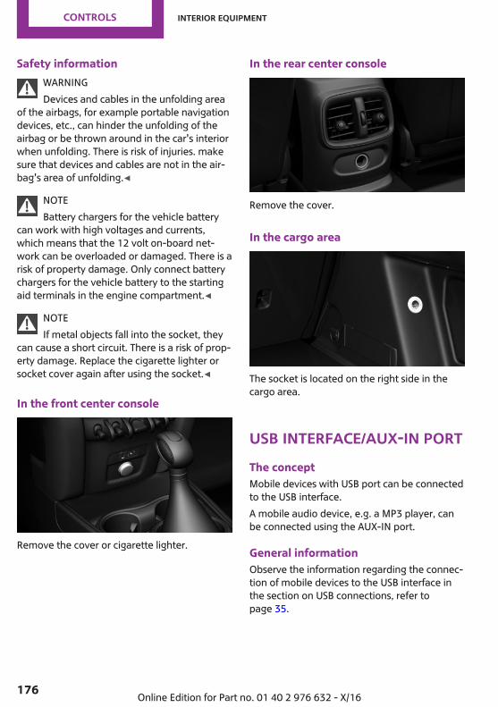
Safety informationWARNINGDevices and cables in the unfolding area
of the airbags, for example portable navigationdevices, etc., can hinder the unfolding of theairbag or be thrown around in the car's interiorwhen unfolding. There is risk of injuries. makesure that devices and cables are not in the air‐bag's area of unfolding.◀
NOTEBattery chargers for the vehicle battery
can work with high voltages and currents,which means that the 12 volt on-board net‐work can be overloaded or damaged. There is arisk of property damage. Only connect batterychargers for the vehicle battery to the startingaid terminals in the engine compartment.◀
NOTEIf metal objects fall into the socket, they
can cause a short circuit. There is a risk of prop‐erty damage. Replace the cigarette lighter orsocket cover again after using the socket.◀
In the front center console
Remove the cover or cigarette lighter.
In the rear center console
Remove the cover.
In the cargo area
The socket is located on the right side in thecargo area.
USB interface/AUX-IN portThe conceptMobile devices with USB port can be connectedto the USB interface.A mobile audio device, e.g. a MP3 player, canbe connected using the AUX-IN port.
General informationObserve the information regarding the connec‐tion of mobile devices to the USB interface inthe section on USB connections, refer topage 35.
Seite 176
CONTROLS Interior equipment
176 Online Edition for Part no. 01 40 2 976 632 - X/16

In the center console
The USB interface and the AUX-IN port are lo‐cated at the front in the center armrest.
Under the center armrest
The USB interface is located under the centerarmrest.
Seite 177
Interior equipment CONTROLS
177Online Edition for Part no. 01 40 2 976 632 - X/16
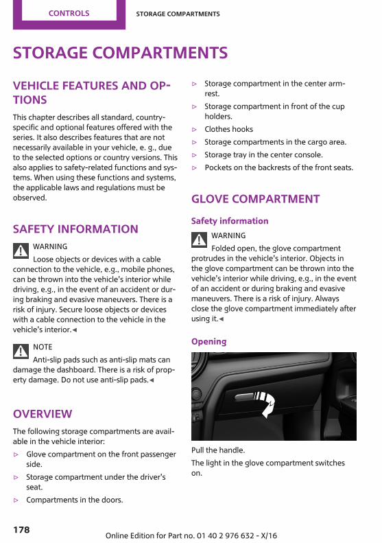
Storage compartmentsVehicle features and op‐tionsThis chapter describes all standard, country-specific and optional features offered with theseries. It also describes features that are notnecessarily available in your vehicle, e. g., dueto the selected options or country versions. Thisalso applies to safety-related functions and sys‐tems. When using these functions and systems,the applicable laws and regulations must beobserved.
Safety informationWARNINGLoose objects or devices with a cable
connection to the vehicle, e.g., mobile phones,can be thrown into the vehicle's interior whiledriving, e.g., in the event of an accident or dur‐ing braking and evasive maneuvers. There is arisk of injury. Secure loose objects or deviceswith a cable connection to the vehicle in thevehicle's interior.◀
NOTEAnti-slip pads such as anti-slip mats can
damage the dashboard. There is a risk of prop‐erty damage. Do not use anti-slip pads.◀
OverviewThe following storage compartments are avail‐able in the vehicle interior:▷ Glove compartment on the front passenger
side.▷ Storage compartment under the driver's
seat.▷ Compartments in the doors.
▷ Storage compartment in the center arm‐rest.
▷ Storage compartment in front of the cupholders.
▷ Clothes hooks▷ Storage compartments in the cargo area.▷ Storage tray in the center console.▷ Pockets on the backrests of the front seats.
Glove compartmentSafety information
WARNINGFolded open, the glove compartment
protrudes in the vehicle's interior. Objects inthe glove compartment can be thrown into thevehicle's interior while driving, e.g., in the eventof an accident or during braking and evasivemaneuvers. There is a risk of injury. Alwaysclose the glove compartment immediately afterusing it.◀
Opening
Pull the handle.The light in the glove compartment switcheson.
Seite 178
CONTROLS Storage compartments
178 Online Edition for Part no. 01 40 2 976 632 - X/16

ClosingFold up the cover.
Driver's seatThere is a storage compartment under the driv‐er's seat.
Compartments in thedoors
WARNINGBreakable objects, e.g., glass bottles, can
break in the event of an accident. Broken glasscan be scattered in the vehicle's interior. Thereis a risk of injury. Do not stow any breakableobjects in the vehicle's interior.◀
Center armrestGeneral informationThe center armrest contains a storage compart‐ment.
Opening
Press button, arrow 1, and open center armrestupward, arrow 2.
Set the inclineThe center armrest can be adjusted in severaltilt settings.
Cup holdersSafety information
WARNINGUnsuitable containers in the cup holder
and hot beverages can damage the cup holderand increase the risk of injury in the event of anaccident. There is a risk of injury or risk of prop‐erty damage. Use light-weight, unbreakable,and sealable containers. Do not transport hotbeverages. Do not force objects into the cupholder.◀
Front
In the center console.
RearIn the center armrest.
Pull the center armrest forward at the strap.To open: press the button.To close: push both covers back in, one afterthe other.
Seite 179
Storage compartments CONTROLS
179Online Edition for Part no. 01 40 2 976 632 - X/16

NOTEWith an open cup holder, the center arm‐
rest cannot be folded back up. There is a risk ofproperty damage. Press back the covers beforethe center armrest is folded up.◀
Clothes hooksWARNINGClothing articles on the clothes hooks can
obstruct the view while driving. There is a riskof an accident. When suspending clothing arti‐cles from the hooks, ensure that they will notobstruct the driver's view.◀
WARNINGImproper use of the clothes hooks can
lead to a risk of objects flying about duringbraking and evasive maneuvers. There is a riskof injury and risk of property damage. Onlyhang lightweight objects, e.g., clothing articles,from the clothes hooks.◀
the clothes hooks are located above the reardoors.
Seite 180
CONTROLS Storage compartments
180 Online Edition for Part no. 01 40 2 976 632 - X/16
Cargo areaVehicle features and op‐tionsThis chapter describes all standard, country-specific and optional features offered with theseries. It also describes features that are notnecessarily available in your vehicle, e. g., dueto the selected options or country versions. Thisalso applies to safety-related functions and sys‐tems. When using these functions and systems,the applicable laws and regulations must beobserved.
LoadingSafety information
WARNINGHigh gross weight can overheat the tires,
damage them internally and cause a suddendrop in tire inflation pressure. Driving charac‐teristics may be negatively impacted, reducinglane stability, lengthening the braking distancesand changing the steering response. There is arisk of an accident. Pay attention to the permit‐ted load capacity of the tires and never exceedthe permitted gross weight.◀
WARNINGLoose objects or devices with a cable
connection to the vehicle, e.g., mobile phones,can be thrown into the vehicle's interior whiledriving, e.g., in the event of an accident or dur‐ing braking and evasive maneuvers. There is arisk of injury. Secure loose objects or deviceswith a cable connection to the vehicle in thevehicle's interior.◀
WARNINGImproperly stowed objects can shift and
be thrown into the vehicle's interior, e.g., in theevent of an accident or during braking and eva‐sive maneuvers. Vehicle occupants can be hitand injured. There is a risk of injury. Stow andsecure objects and cargo properly.◀
NOTEFluids in the cargo area can cause dam‐
age. There is a risk of property damage. Makesure that no fluids leak in the cargo area.◀
Steps for Determining Correct LoadLimit1. Locate the statement “The combined
weight of occupants and cargo shouldnever exceed XXX kg or XXX lbs.” on yourvehicle’s placard.
2. Determine the combined weight of thedriver and passengers that will be riding inyour vehicle.
3. Subtract the combined weight of the driverand passengers from XXX kg or XXX lbs.
4. The resulting figure equals the availableamount of cargo and luggage load ca‐pacity. For example, if the “XXX” amountequals 1,400 lbs. and there will be five150 lb passengers in your vehicle, theamount of available cargo and luggageload capacity is 650 lbs. (1,400–750 (5 x150) = 650 lbs.)
5. Determine the combined weight of luggageand cargo being loaded on the vehicle.That weight may not safely exceed theavailable cargo and luggage load capacitycalculated in Step 4.
6. If your vehicle will be towing a trailer, loadfrom your trailer will be transferred to yourvehicle. Consult this manual to determine
Seite 181
Cargo area CONTROLS
181Online Edition for Part no. 01 40 2 976 632 - X/16
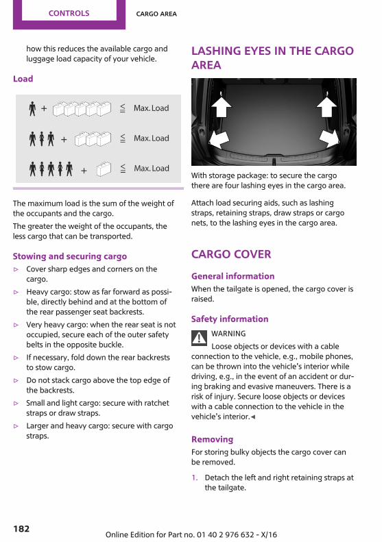
how this reduces the available cargo andluggage load capacity of your vehicle.
Load
The maximum load is the sum of the weight ofthe occupants and the cargo.The greater the weight of the occupants, theless cargo that can be transported.
Stowing and securing cargo▷ Cover sharp edges and corners on the
cargo.▷ Heavy cargo: stow as far forward as possi‐
ble, directly behind and at the bottom ofthe rear passenger seat backrests.
▷ Very heavy cargo: when the rear seat is notoccupied, secure each of the outer safetybelts in the opposite buckle.
▷ If necessary, fold down the rear backreststo stow cargo.
▷ Do not stack cargo above the top edge ofthe backrests.
▷ Small and light cargo: secure with ratchetstraps or draw straps.
▷ Larger and heavy cargo: secure with cargostraps.
Lashing eyes in the cargoarea
With storage package: to secure the cargothere are four lashing eyes in the cargo area.
Attach load securing aids, such as lashingstraps, retaining straps, draw straps or cargonets, to the lashing eyes in the cargo area.
Cargo coverGeneral informationWhen the tailgate is opened, the cargo cover israised.
Safety informationWARNINGLoose objects or devices with a cable
connection to the vehicle, e.g., mobile phones,can be thrown into the vehicle's interior whiledriving, e.g., in the event of an accident or dur‐ing braking and evasive maneuvers. There is arisk of injury. Secure loose objects or deviceswith a cable connection to the vehicle in thevehicle's interior.◀
RemovingFor storing bulky objects the cargo cover canbe removed.
1. Detach the left and right retaining straps atthe tailgate.
Seite 182
CONTROLS Cargo area
182 Online Edition for Part no. 01 40 2 976 632 - X/16
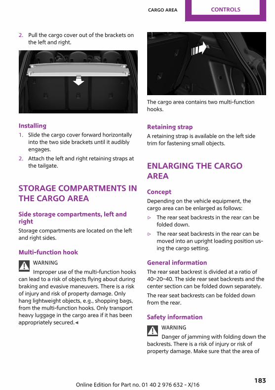
2. Pull the cargo cover out of the brackets onthe left and right.
Installing1. Slide the cargo cover forward horizontally
into the two side brackets until it audiblyengages.
2. Attach the left and right retaining straps atthe tailgate.
Storage compartments inthe cargo areaSide storage compartments, left andrightStorage compartments are located on the leftand right sides.
Multi-function hookWARNINGImproper use of the multi-function hooks
can lead to a risk of objects flying about duringbraking and evasive maneuvers. There is a riskof injury and risk of property damage. Onlyhang lightweight objects, e.g., shopping bags,from the multi-function hooks. Only transportheavy luggage in the cargo area if it has beenappropriately secured.◀
The cargo area contains two multi-functionhooks.
Retaining strapA retaining strap is available on the left sidetrim for fastening small objects.
Enlarging the cargoareaConceptDepending on the vehicle equipment, thecargo area can be enlarged as follows:▷ The rear seat backrests in the rear can be
folded down.▷ The rear seat backrests in the rear can be
moved into an upright loading position us‐ing the cargo setting.
General informationThe rear seat backrest is divided at a ratio of40–20–40. The side rear seat backrests and thecenter section can be folded down separately.The rear seat backrests can be folded downfrom the rear.
Safety informationWARNINGDanger of jamming with folding down the
backrests. There is a risk of injury or risk ofproperty damage. Make sure that the area of
Seite 183
Cargo area CONTROLS
183Online Edition for Part no. 01 40 2 976 632 - X/16
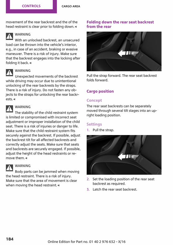
movement of the rear backrest and the of thehead restraint is clear prior to folding down.◀
WARNINGWith an unlocked backrest, an unsecured
load can be thrown into the vehicle's interior,e.g., in case of an accident, braking or evasivemaneuver. There is a risk of injury. Make surethat the backrest engages into the locking afterfolding it back.◀
WARNINGUnexpected movements of the backrest
while driving may occur due to unintentionalunlocking of the rear backrests by the straps.There is a risk of injury. Do not fasten any ob‐jects to the straps for unlocking the rear backr‐ests.◀
WARNINGThe stability of the child restraint system
is limited or compromised with incorrect seatadjustment or improper installation of the childseat. There is a risk of injuries or danger to life.Make sure that the child restraint system fitssecurely against the backrest. If possible, adjustthe backrest tilt for all affected backrests andcorrectly adjust the seats. Make sure that seatsand backrests are securely engaged. If possible,adjust the height of the head restraints or re‐move them.◀
WARNINGBody parts can be jammed when moving
the head restraint. There is a risk of injury.Make sure that the area of movement is clearwhen moving the head restraint.◀
Folding down the rear seat backrestfrom the rear
Pull the strap forward. The rear seat backrestfolds forward.
Cargo position
ConceptThe rear seat backrests can be separatelymoved through several tilt stages into an up‐right loading position.
Settings1. Pull the strap.
2. Set the loading position of the rear seatbackrest as required.
3. Latch the rear seat backrest.
Seite 184
CONTROLS Cargo area
184 Online Edition for Part no. 01 40 2 976 632 - X/16
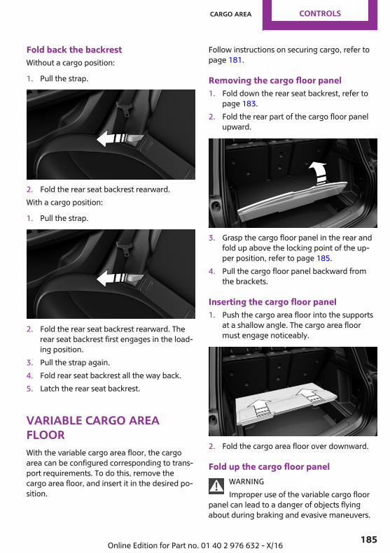
Fold back the backrestWithout a cargo position:
1. Pull the strap.
2. Fold the rear seat backrest rearward.With a cargo position:
1. Pull the strap.
2. Fold the rear seat backrest rearward. Therear seat backrest first engages in the load‐ing position.
3. Pull the strap again.4. Fold rear seat backrest all the way back.5. Latch the rear seat backrest.
Variable cargo areafloorWith the variable cargo area floor, the cargoarea can be configured corresponding to trans‐port requirements. To do this, remove thecargo area floor, and insert it in the desired po‐sition.
Follow instructions on securing cargo, refer topage 181.
Removing the cargo floor panel1. Fold down the rear seat backrest, refer to
page 183.2. Fold the rear part of the cargo floor panel
upward.
3. Grasp the cargo floor panel in the rear andfold up above the locking point of the up‐per position, refer to page 185.
4. Pull the cargo floor panel backward fromthe brackets.
Inserting the cargo floor panel1. Push the cargo area floor into the supports
at a shallow angle. The cargo area floormust engage noticeably.
2. Fold the cargo area floor over downward.
Fold up the cargo floor panelWARNINGImproper use of the variable cargo floor
panel can lead to a danger of objects flyingabout during braking and evasive maneuvers.
Seite 185
Cargo area CONTROLS
185Online Edition for Part no. 01 40 2 976 632 - X/16

There is risk of injuries and risk of propertydamage.▷ Do not use the variable cargo floor panel to
separate the cargo area and vehicle interiorin the sense of a partition net.
▷ Only use the variable cargo floor in thefolded-up position when the backrests arefolded up and locked.
▷ Always secure cargo against shifting, usingstraps, belts and lashing eyes, for exam‐ple.◀
Fold the rear part of the cargo floor panel up‐ward.
Fold up the cargo floor panel. You've reachedthe maximum cargo height.
MINI Picnic BenchConceptThe MINI Picnic Bench provides a comfortableseating surface on the loading lip of the vehicle.
General informationOnly use the MINI Picnic Bench while the vehi‐cle is parked and with the tailgate open. Whenthe MINI Picnic Bench is not in use, fold it to‐gether to prevent soiling and damage.In vehicles with a no-touch opening and closingtailgate:If the remote control is in the sensor area, thetailgate can be opened or closed inadvertently
by an unconscious or alleged recognized footmovement.The sensor has an approximate range of5 ft/1.50 m extending from the rear of the vehi‐cle.
Safety informationWARNINGBody parts can be jammed when operat‐
ing the tailgate. There is a risk of injury. Makesure that the area of movement of the tailgateis clear during opening and closing.◀
OverviewThe MINI Picnic Bench is located on the under‐side of the cargo area floor.
Mounting1. Fold the rear part of the cargo floor panel
upward.
2. Place the MINI Picnic Bench on the part ofthe cargo area floor that is folded over andattach it using the four snaps.
3. Fold the rear part of the cargo area floordownward.
Seite 186
CONTROLS Cargo area
186 Online Edition for Part no. 01 40 2 976 632 - X/16
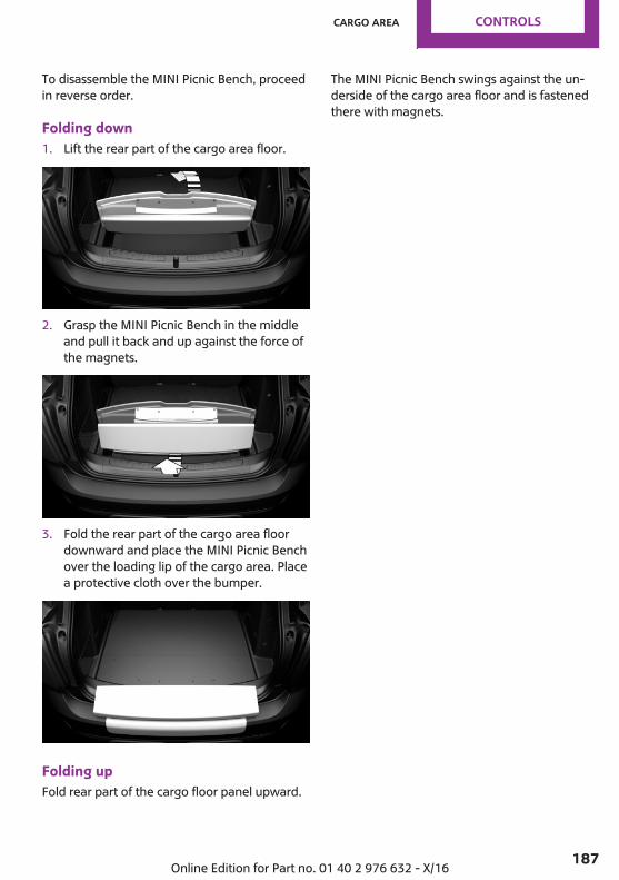
To disassemble the MINI Picnic Bench, proceedin reverse order.
Folding down1. Lift the rear part of the cargo area floor.
2. Grasp the MINI Picnic Bench in the middleand pull it back and up against the force ofthe magnets.
3. Fold the rear part of the cargo area floordownward and place the MINI Picnic Benchover the loading lip of the cargo area. Placea protective cloth over the bumper.
Folding upFold rear part of the cargo floor panel upward.
The MINI Picnic Bench swings against the un‐derside of the cargo area floor and is fastenedthere with magnets.
Seite 187
Cargo area CONTROLS
187Online Edition for Part no. 01 40 2 976 632 - X/16
DRIVE ME.
Online Edition for Part no. 01 40 2 976 632 - X/16
AT A GLANCE
CONTROLS
DRIVING TIPS
MOBILITY
REFERENCE
Online Edition for Part no. 01 40 2 976 632 - X/16
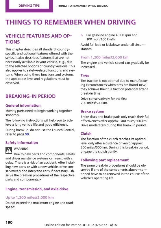
Things to remember when drivingVehicle features and op‐tionsThis chapter describes all standard, country-specific and optional features offered with theseries. It also describes features that are notnecessarily available in your vehicle, e. g., dueto the selected options or country versions. Thisalso applies to safety-related functions and sys‐tems. When using these functions and systems,the applicable laws and regulations must beobserved.
Breaking-in periodGeneral informationMoving parts need to begin working togethersmoothly.The following instructions will help you to ach‐ieve a long vehicle life and good efficiency.During break-in, do not use the Launch Control,refer to page 99.
Safety informationWARNINGDue to new parts and components, safety
and driver assistance systems can react with adelay. There is a risk of an accident. After instal‐ling new parts or with a new vehicle, drive con‐servatively and intervene early if necessary. Ob‐serve the break-in procedures of the respectiveparts and components.◀
Engine, transmission, and axle drive
Up to 1,200 miles/2,000 kmDo not exceed the maximum engine and roadspeed:
▷ For gasoline engine 4,500 rpm and100 mph/160 km/h.
Avoid full load or kickdown under all circum‐stances.
From 1,200 miles/2,000 kmThe engine and vehicle speed can gradually beincreased.
TiresTire traction is not optimal due to manufactur‐ing circumstances when tires are brand-new;they achieve their full traction potential after abreak-in time.Drive conservatively for the first200 miles/300 km.
Brake systemBrake discs and brake pads only reach their fulleffectiveness after approx. 300 miles/500 km.Drive moderately during this break-in period.
ClutchThe function of the clutch reaches its optimallevel only after a distance driven of approx.300 miles/500 km. During this break-in period,engage the clutch gently.
Following part replacementThe same break-in procedures should be ob‐served if any of the components above-men‐tioned have to be renewed in the course of thevehicle's operating life.
Seite 190
DRIVING TIPS Things to remember when driving
190 Online Edition for Part no. 01 40 2 976 632 - X/16
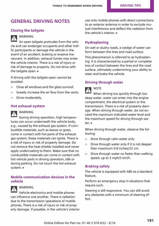
General driving notesClosing the tailgate
WARNINGAn open tailgate protrudes from the vehi‐
cle and can endanger occupants and other traf‐fic participants or damage the vehicle in theevent of an accident, braking or evasive ma‐neuvers. In addition, exhaust fumes may enterthe vehicle interior. There is a risk of injury orrisk of damage to property. Do not drive withthe tailgate open.◀
If driving with the tailgate open cannot beavoided:▷ Close all windows and the glass sunroof.▷ Greatly increase the air flow from the vents.▷ Drive moderately.
Hot exhaust systemWARNINGDuring driving operation, high tempera‐
tures can occur underneath the vehicle body,e.g., caused by the exhaust gas system. If com‐bustible materials, such as leaves or grass,come in contact with hot parts of the exhaustgas system, these materials can ignite. There isa risk of injury or risk of property damage. Donot remove the heat shields installed and neverapply undercoating to them. Make sure that nocombustible materials can come in contact withhot vehicle parts in driving operation, idle orduring parking. Do not touch the hot exhaustsystem.◀
Mobile communication devices in thevehicle
WARNINGVehicle electronics and mobile phones
can influence one another. There is radiationdue to the transmission operations of mobilephones. There is a risk of injury or risk of prop‐erty damage. If possible, in the vehicle's interior
use only mobile phones with direct connectionsto an exterior antenna in order to exclude mu‐tual interference and deflect the radiation fromthe vehicle's interior.◀
HydroplaningOn wet or slushy roads, a wedge of water canform between the tires and road surface.This phenomenon is referred to as hydroplan‐ing. It is characterized by a partial or completeloss of contact between the tires and the roadsurface, ultimately undermining your ability tosteer and brake the vehicle.
Driving through waterNOTEWhen driving too quickly through too
deep water, water can enter into the enginecompartment, the electrical system or thetransmission. There is a risk of property dam‐age. When driving through water, do not ex‐ceed the maximum indicated water level andthe maximum speed for driving through wa‐ter.◀
When driving through water, observe the fol‐lowing:▷ Drive through calm water only.▷ Drive through water only if it is not deeper
than maximum 9.8 inches/25 cm.▷ Drive through water no faster than walking
speed, up to 3 mph/5 km/h.
Braking safelyThe vehicle is equipped with ABS as a standardfeature.Perform an emergency stop in situations thatrequire such.Steering is still responsive. You can still avoidany obstacles with a minimum of steering ef‐fort.
Seite 191
Things to remember when driving DRIVING TIPS
191Online Edition for Part no. 01 40 2 976 632 - X/16
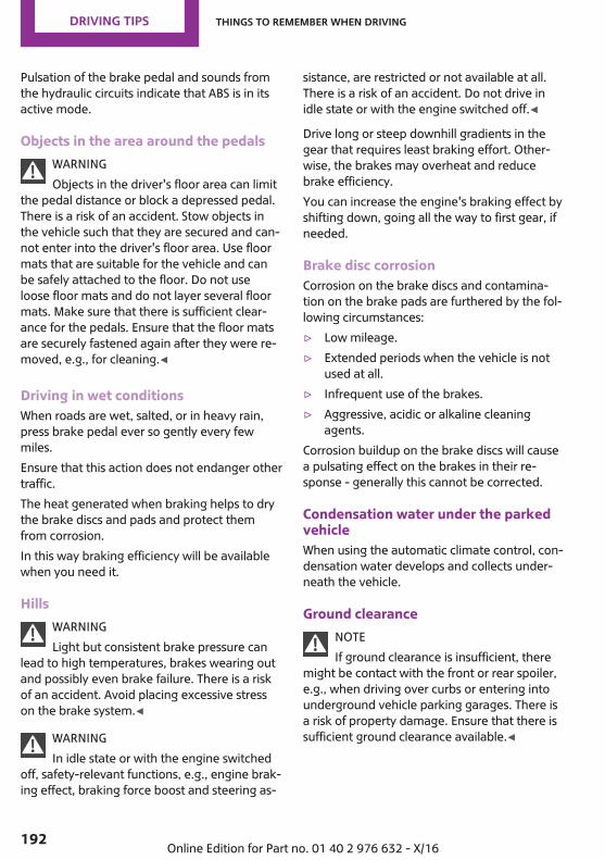
Pulsation of the brake pedal and sounds fromthe hydraulic circuits indicate that ABS is in itsactive mode.
Objects in the area around the pedalsWARNINGObjects in the driver's floor area can limit
the pedal distance or block a depressed pedal.There is a risk of an accident. Stow objects inthe vehicle such that they are secured and can‐not enter into the driver's floor area. Use floormats that are suitable for the vehicle and canbe safely attached to the floor. Do not useloose floor mats and do not layer several floormats. Make sure that there is sufficient clear‐ance for the pedals. Ensure that the floor matsare securely fastened again after they were re‐moved, e.g., for cleaning.◀
Driving in wet conditionsWhen roads are wet, salted, or in heavy rain,press brake pedal ever so gently every fewmiles.Ensure that this action does not endanger othertraffic.The heat generated when braking helps to drythe brake discs and pads and protect themfrom corrosion.In this way braking efficiency will be availablewhen you need it.
HillsWARNINGLight but consistent brake pressure can
lead to high temperatures, brakes wearing outand possibly even brake failure. There is a riskof an accident. Avoid placing excessive stresson the brake system.◀
WARNINGIn idle state or with the engine switched
off, safety-relevant functions, e.g., engine brak‐ing effect, braking force boost and steering as‐
sistance, are restricted or not available at all.There is a risk of an accident. Do not drive inidle state or with the engine switched off.◀
Drive long or steep downhill gradients in thegear that requires least braking effort. Other‐wise, the brakes may overheat and reducebrake efficiency.You can increase the engine's braking effect byshifting down, going all the way to first gear, ifneeded.
Brake disc corrosionCorrosion on the brake discs and contamina‐tion on the brake pads are furthered by the fol‐lowing circumstances:▷ Low mileage.▷ Extended periods when the vehicle is not
used at all.▷ Infrequent use of the brakes.▷ Aggressive, acidic or alkaline cleaning
agents.Corrosion buildup on the brake discs will causea pulsating effect on the brakes in their re‐sponse - generally this cannot be corrected.
Condensation water under the parkedvehicleWhen using the automatic climate control, con‐densation water develops and collects under‐neath the vehicle.
Ground clearanceNOTEIf ground clearance is insufficient, there
might be contact with the front or rear spoiler,e.g., when driving over curbs or entering intounderground vehicle parking garages. There isa risk of property damage. Ensure that there issufficient ground clearance available.◀
Seite 192
DRIVING TIPS Things to remember when driving
192 Online Edition for Part no. 01 40 2 976 632 - X/16
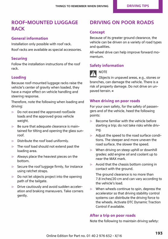
Roof-mounted luggagerackGeneral informationInstallation only possible with roof rack.Roof racks are available as special accessories.
SecuringFollow the installation instructions of the roofrack.
LoadingBecause roof-mounted luggage racks raise thevehicle's center of gravity when loaded, theyhave a major effect on vehicle handling andsteering response.Therefore, note the following when loading anddriving:▷ Do not exceed the approved roof/axle
loads and the approved gross vehicleweight.
▷ Be sure that adequate clearance is main‐tained for tilting and opening the glass sun‐roof.
▷ Distribute the roof load uniformly.▷ The roof load should not extend past the
loading area.▷ Always place the heaviest pieces on the
bottom.▷ Secure the roof luggage firmly, for instance
using ratchet straps.▷ Do not let objects project into the opening
path of the tailgate.▷ Drive cautiously and avoid sudden acceler‐
ation and braking maneuvers. Take cornersgently.
Driving on poor roadsConceptBecause of its greater ground clearance, thevehicle can be driven on a variety of road typesand qualities.All-wheel drive can help improve forward mo‐mentum.
Safety informationNOTEObjects in unpaved areas, e.g., stones or
branches, can damage the vehicle. There is arisk of property damage. Do not drive on un‐paved terrain.◀
When driving on poor roadsFor your own safety, for the safety of passen‐gers and of the vehicle, heed the followingpoints:▷ Become familiar with the vehicle before
starting a trip; do not take risks while driv‐ing.
▷ Adjust the speed to the road surface condi‐tions. The steeper and more uneven theroad surface, the slower the speed.
▷ When driving on steep uphill or downhillgrades: add engine oil and coolant up tonear the MAX mark.
▷ Avoid that the chassis bottom coming incontact with the ground.The ground clearance is no more than7.8 inches/20 cm and can vary according tothe vehicle's load.
▷ When wheels continue to spin, depress theaccelerator so that driving stability controlsystems can distribute the driving force tothe wheels. Activate DTC Dynamic TractionControl if available.
After a trip on poor roadsNote the following to maintain driving safety:
Seite 193
Things to remember when driving DRIVING TIPS
193Online Edition for Part no. 01 40 2 976 632 - X/16

▷ Clear heavy soiling from the body.▷ Keep the wheels and tires free of mud,
snow, ice, etc., and check them for dam‐age.
Driving on racetracksHigher mechanical and thermal loads duringracetrack operation lead to increased wear.This wear is not covered by the warranty. Thevehicle is not designed for use in motor sportscompetition.
Seite 194
DRIVING TIPS Things to remember when driving
194 Online Edition for Part no. 01 40 2 976 632 - X/16
Saving fuelVehicle features and op‐tionsThis chapter describes all standard, country-specific and optional features offered with theseries. It also describes features that are notnecessarily available in your vehicle, e. g., dueto the selected options or country versions. Thisalso applies to safety-related functions and sys‐tems. When using these functions and systems,the applicable laws and regulations must beobserved.
General informationThe vehicle features advanced technology forthe reduction of fuel consumption and emis‐sions.Fuel consumption depends on a number of dif‐ferent factors.The implementation of certain measures, driv‐ing style and regular maintenance can influ‐ence fuel consumption and environmental im‐pact.
Remove unnecessarycargoAdditional weight increases fuel consumption.
Remove attached partsfollowing useRemove auxiliary mirrors, roof-mounted or rearluggage racks which are no longer required fol‐lowing use.Attached parts on the vehicle impair the aero‐dynamics and increase the fuel consumption.
Close the windows andglass sunroofDriving with the glass sunroof and windowsopen results in increased air resistance andraises fuel consumption.
TiresGeneral informationTires can affect fuel consumption in variousways, for example, tire size may influence fuelconsumption.
Check the tire inflation pressureregularlyCheck and, if needed, correct the tire inflationpressure at least twice a month and beforestarting on a long trip.Low tire inflation pressure increases rolling re‐sistance and thus raises fuel consumption andtire wear.
Drive away without de‐layDo not wait for the engine to warm-up whilethe vehicle remains stationary. Start drivingright away, but at moderate engine speeds.This is the fastest way for the cold engine toreach its operating temperature.
Look well ahead whendrivingDriving smoothly and proactively reduces fuelconsumption.
Seite 195
Saving fuel DRIVING TIPS
195Online Edition for Part no. 01 40 2 976 632 - X/16
Avoid unnecessary acceleration and braking.By maintaining a suitable distance to the vehi‐cle driving ahead of you.
Avoid high engine speedsAs a rule: driving at low engine speeds lowersfuel consumption and reduces wear.Use 1st gear to get the vehicle moving. Startingwith the 2nd gear, accelerate rapidly. When ac‐celerating, shift up before reaching high enginespeeds.When you reach the desired speed, shift intothe highest applicable gear and drive with lowengine speed and at a constant speed.If necessary, observe the vehicle's gear shift in‐dicator, refer to page 107.
Use coasting conditionsWhen approaching a red light, take your footoff the accelerator and let the vehicle coast to ahalt.For going downhill take your foot off the accel‐erator and let the vehicle roll.The flow of fuel is interrupted while coasting.
Switch off the engineduring longer stopsSwitch off the engine during longer stops, e.g.,at traffic lights, railroad crossings or in trafficcongestion.
Auto Start/Stop functionThe Auto Start/Stop function of the vehicle au‐tomatically switches off the engine during astop.If the engine is switched off and then restartedrather than leaving the engine running con‐stantly, fuel consumption and emissions are re‐
duced. Savings can begin within a few secondsof switching off the engine.In addition, fuel consumption is also deter‐mined by other factors, such as driving style,road conditions, maintenance or environmentalfactors.
Switch off any functionsthat are not currentlyneededFunctions such as seat heating and the rearwindow defroster require a lot of energy andconsume additional fuel, especially in city andstop-and-go traffic.Switch off these functions if they are notneeded.
Have maintenance car‐ried outHave vehicles maintained regularly to achieveoptimal vehicle efficiency and service life. MINIrecommends that maintenance work be per‐formed by a MINI service center.Also note the MINI maintenance systems, referto page 232.
GREEN ModeConceptGREEN Mode supports a driving style that saveson fuel consumption. For this purpose, the en‐gine control and comfort features, for instancethe climate control output, are adjusted.For Steptronic transmission:Under certain conditions the engine is auto‐matically decoupled from the transmission inthe D selector lever position. The vehicle con‐tinues traveling with the engine idling to re‐
Seite 196
DRIVING TIPS Saving fuel
196 Online Edition for Part no. 01 40 2 976 632 - X/16
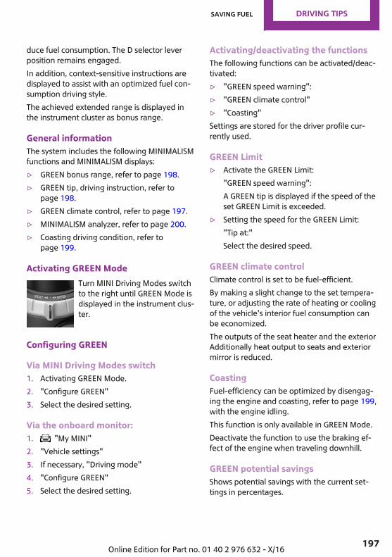
duce fuel consumption. The D selector leverposition remains engaged.In addition, context-sensitive instructions aredisplayed to assist with an optimized fuel con‐sumption driving style.The achieved extended range is displayed inthe instrument cluster as bonus range.
General informationThe system includes the following MINIMALISMfunctions and MINIMALISM displays:▷ GREEN bonus range, refer to page 198.▷ GREEN tip, driving instruction, refer to
page 198.▷ GREEN climate control, refer to page 197.▷ MINIMALISM analyzer, refer to page 200.▷ Coasting driving condition, refer to
page 199.
Activating GREEN ModeTurn MINI Driving Modes switchto the right until GREEN Mode isdisplayed in the instrument clus‐ter.
Configuring GREEN
Via MINI Driving Modes switch1. Activating GREEN Mode.2. "Configure GREEN"3. Select the desired setting.
Via the onboard monitor:1. "My MINI"2. "Vehicle settings"3. If necessary, "Driving mode"4. "Configure GREEN"5. Select the desired setting.
Activating/deactivating the functionsThe following functions can be activated/deac‐tivated:▷ "GREEN speed warning":▷ "GREEN climate control"▷ "Coasting"Settings are stored for the driver profile cur‐rently used.
GREEN Limit▷ Activate the GREEN Limit:
"GREEN speed warning":A GREEN tip is displayed if the speed of theset GREEN Limit is exceeded.
▷ Setting the speed for the GREEN Limit:"Tip at:"Select the desired speed.
GREEN climate controlClimate control is set to be fuel-efficient.By making a slight change to the set tempera‐ture, or adjusting the rate of heating or coolingof the vehicle's interior fuel consumption canbe economized.The outputs of the seat heater and the exteriorAdditionally heat output to seats and exteriormirror is reduced.
CoastingFuel-efficiency can be optimized by disengag‐ing the engine and coasting, refer to page 199,with the engine idling.This function is only available in GREEN Mode.Deactivate the function to use the braking ef‐fect of the engine when traveling downhill.
GREEN potential savingsShows potential savings with the current set‐tings in percentages.
Seite 197
Saving fuel DRIVING TIPS
197Online Edition for Part no. 01 40 2 976 632 - X/16
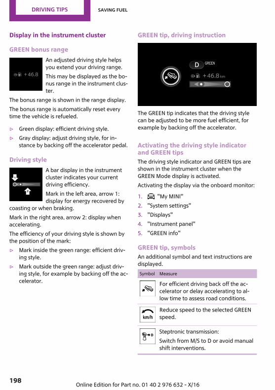
Display in the instrument cluster
GREEN bonus rangeAn adjusted driving style helpsyou extend your driving range.This may be displayed as the bo‐nus range in the instrument clus‐ter.
The bonus range is shown in the range display.The bonus range is automatically reset everytime the vehicle is refueled.
▷ Green display: efficient driving style.▷ Gray display: adjust driving style, for in‐
stance by backing off the accelerator pedal.
Driving styleA bar display in the instrumentcluster indicates your currentdriving efficiency.Mark in the left area, arrow 1:display for energy recovered by
coasting or when braking.Mark in the right area, arrow 2: display whenaccelerating.The efficiency of your driving style is shown bythe position of the mark:▷ Mark inside the green range: efficient driv‐
ing style.▷ Mark outside the green range: adjust driv‐
ing style, for example by backing off the ac‐celerator.
GREEN tip, driving instruction
The GREEN tip indicates that the driving stylecan be adjusted to be more fuel efficient, forexample by backing off the accelerator.
Activating the driving style indicatorand GREEN tipsThe driving style indicator and GREEN tips areshown in the instrument cluster when theGREEN Mode display is activated.Activating the display via the onboard monitor:
1. "My MINI"2. "System settings"3. "Displays"4. "Instrument panel"5. "GREEN info"
GREEN tip, symbolsAn additional symbol and text instructions aredisplayed.Symbol Measure
For efficient driving back off the ac‐celerator or delay accelerating to al‐low time to assess road conditions.
Reduce speed to the selected GREENspeed.
Steptronic transmission:Switch from M/S to D or avoid manualshift interventions.
Seite 198
DRIVING TIPS Saving fuel
198 Online Edition for Part no. 01 40 2 976 632 - X/16
Symbol Measure
Manual transmission:Follow the shift instructions.
Manual transmission:Engage neutral for an engine stop.
Indications on the Control Display
Displaying MINIMALISM informationThe current efficiency of the functions in GREENMode can be displayed on the Control Display.Via the onboard monitor:
1. "My MINI"2. "Technology in action"3. "MINIMALISM"Information is shown on the following func‐tions:▷ Auto Start/Stop function.▷ Energy recovery.▷ Climate control output.▷ Coasting.
Displaying the MINIMALISM analyzerVia the onboard monitor:
1. "My MINI"2. "Technology in action"3. "MINIMALISM Analyser"Further information on the MINIMALISM ana‐lyzer, refer to page 200.
Coasting
ConceptThe function helps to conserve fuel.To do this, under certain conditions the engineis automatically decoupled from the transmis‐sion when selector lever position D is set. Thevehicle continues traveling with the engine
idling to reduce fuel consumption. Selectorlever position D remains engaged.This driving condition is referred to as coasting.As soon as you step on the brake or acceleratorpedal, the engine is automatically coupledagain.
General informationCoasting is a component of the GREEN drivingmode.Coasting is automatically activated when theGREEN driving mode is called via the MINI Driv‐ing Modes switch, refer to page 143.A proactive driving style helps the driver to usethe function often and supports the fuel-con‐serving effect of coasting.
Functional requirementsIn GREEN mode, this function is available in aspeed range from approximately30 mph/50 km/h to 100 mph/160 km/h if thefollowing conditions are met:▷ Accelerator pedal and brake pedal are not
operated.▷ The selector lever is in selector lever posi‐
tion D.▷ Engine and transmission are at operating
temperature.
Operation via shift paddles
ConceptDepending on your vehicle's equipment, thecoasting mode can be influenced with the shiftpaddles.
Activating/deactivating coasting via shiftpaddles1. Shift to the highest gear by pulling the right
shift paddle.2. Actuate the right shift paddle again to enter
coasting mode.To deactivate, actuate the left shift paddle.
Seite 199
Saving fuel DRIVING TIPS
199Online Edition for Part no. 01 40 2 976 632 - X/16
Display
Display in the instrument clusterThe bar display below the tach‐ometer is filled in green and themark appears at the zero point.The tachometer approximatelyindicates idle speed.
Indications on the Control DisplayThe coasting driving condition is displayed inthe MINIMALISM Info while driving.The distance traveled in the coasting drivingcondition is indicated by a counter.
Displaying MINIMALISM informationVia the onboard monitor:
1. "My MINI"2. "Technology in action"3. "MINIMALISM"
System limitsThe function is not available if one of the fol‐lowing conditions applies:▷ DSC OFF and TRACTION are activated.▷ Cruise control is activated.▷ If driving in the dynamic limit range.▷ If driving on steep uphill or downhill grades.▷ The battery charge state is temporarily too
low.▷ The vehicle electrical system is drawing ex‐
cessive current.
MINIMALISM analyzer
ConceptThe function helps develop an especially effi‐cient driving style and to conserve fuel.For this purpose, the driving style is analyzed.The assessment is done in various categoriesand is displayed on the Control Display.
Using this indication, the individual driving stylecan be oriented toward conserving fuel.The last 15 minutes of a trip are evaluated.The range of the vehicle can be extended by anefficient driving style. This gain in range is dis‐played as a bonus range in the instrument clus‐ter and on the Control Display.
Functional requirementThis function is available in GREEN Mode.
Displaying the MINIMALISM analyzerVia the onboard monitor:
1. "My MINI"2. "Technology in action"3. "MINIMALISM Analyser"
Display on the Control DisplayThe display of the MINIMALISM analyzer con‐sists of a fish in a water glass, a table of valuesand the display of the achieved bonus range.The fish and the movements of the water in theglass symbolize the efficiency of the drivingstyle.The more efficient the driving style, the less thewater sloshes around in the glass and the bet‐ter is the fish's mood. If the driving style is inef‐ficient, the water oscillates, the mood of thefish is sullied and a reduced number of asterisksis displayed.The table of values contains stars and evaluatesthe driving style in different categories. Themore efficient the driving style, the more starsare displayed in the table.The bonus range achieved by a driving stylethat minimizes fuel consumption is displayedbelow the table of values. The more efficientthe driving style, the faster the bonus range in‐creases.To assist with an efficient driving style, GREENtips are displayed while driving.
Seite 200
DRIVING TIPS Saving fuel
200 Online Edition for Part no. 01 40 2 976 632 - X/16
Tips about the energy saving driving style, Con‐serving fuel, refer to page 195.
Seite 201
Saving fuel DRIVING TIPS
201Online Edition for Part no. 01 40 2 976 632 - X/16
MOVE ME.
Online Edition for Part no. 01 40 2 976 632 - X/16

AT A GLANCE
CONTROLS
DRIVING TIPS
MOBILITY
REFERENCE
Online Edition for Part no. 01 40 2 976 632 - X/16
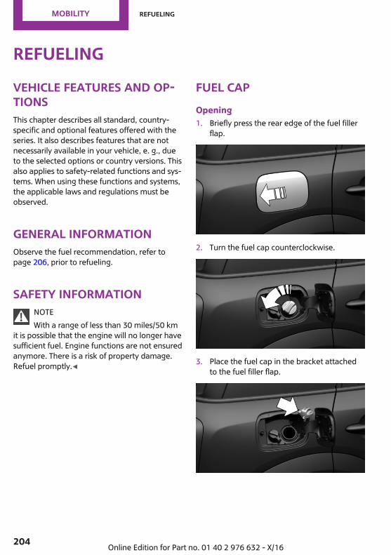
RefuelingVehicle features and op‐tionsThis chapter describes all standard, country-specific and optional features offered with theseries. It also describes features that are notnecessarily available in your vehicle, e. g., dueto the selected options or country versions. Thisalso applies to safety-related functions and sys‐tems. When using these functions and systems,the applicable laws and regulations must beobserved.
General informationObserve the fuel recommendation, refer topage 206, prior to refueling.
Safety informationNOTEWith a range of less than 30 miles/50 km
it is possible that the engine will no longer havesufficient fuel. Engine functions are not ensuredanymore. There is a risk of property damage.Refuel promptly.◀
Fuel capOpening1. Briefly press the rear edge of the fuel filler
flap.
2. Turn the fuel cap counterclockwise.
3. Place the fuel cap in the bracket attachedto the fuel filler flap.
Seite 204
MOBILITY Refueling
204 Online Edition for Part no. 01 40 2 976 632 - X/16
ClosingWARNINGThe retaining strap of the fuel cap can be
jammed and crushed during closing. The capcannot be correctly closed. Fuel or fuel vaporscan escape. There is a risk of injury or risk ofproperty damage. Pay attention that the retain‐ing strap is not jammed or crushed when clos‐ing the lid.◀
1. Fit the cap and turn it clockwise until youclearly hear a click.
2. Close the fuel filler flap.
Manually unlocking fuel filler flapE.g., in the event of an electrical malfunction.Have the fuel filler flap checked by a dealer’sservice center or another qualified service cen‐ter or repair shop.
Observe the followingwhen refuelingGeneral informationThe fuel tank is full when the filler nozzle clicksoff the first time.Observe safety regulations posted at the gasstation.
Safety informationNOTEFuels are toxic and aggressive. Overfilling
of the fuel tank can damage the fuel system.Painted surfaces may be damaged by contactwith fuel. Escaping fuel can harm the environ‐ment. There is a risk of property damage. Avoidoverfilling.◀
Seite 205
Refueling MOBILITY
205Online Edition for Part no. 01 40 2 976 632 - X/16

FuelVehicle features and op‐tionsThis chapter describes all standard, country-specific and optional features offered with theseries. It also describes features that are notnecessarily available in your vehicle, e. g., dueto the selected options or country versions. Thisalso applies to safety-related functions and sys‐tems. When using these functions and systems,the applicable laws and regulations must beobserved.
Fuel recommendationGeneral informationDepending on the region, many gas stationssell fuel that has been customized to winter orsummer conditions. Fuel that is available inwinter helps make a cold start easier, for exam‐ple.
Gasoline
General informationFor the best fuel efficiency, the gasoline shouldbe sulfur-free or very low in sulfur content.Fuels that are marked on the gas pump as con‐taining metal must not be used.Fuels with a maximum ethanol content of25 %, i. e. E10 or E25, may be used for refuel‐ing.Ethanol should meet the following qualitystandards:US: ASTM 4806–xxCAN: CGSB-3.511–xxxx: comply with the current standard in eachcase.
Safety informationNOTEDo not press the Start/Stop button after
refueling with the wrong fuel. Furthermore, thecatalytic converter is permanently damaged.There is a risk of property damage. Do not re‐fuel or add the following in the case of gasolineengines:▷ Leaded gasoline.▷ Metallic additives, e.g., manganese or iron.Do not press the Start/Stop button after refuel‐ing with the wrong fuel. Contact a dealer’s serv‐ice center or another qualified service center orrepair shop.◀
NOTEIncorrect fuels can damage the fuel sys‐
tem and the engine. There is a risk of damageto property. Do not use fuels with a higher per‐centage of ethanol than recommended. Do notrefuel with fuels containing methanol, e.g. M5to M100.◀
NOTEFuel that does not comply with the mini‐
mum quality can compromise engine functionor cause engine damage. There is a risk ofproperty damage. Do not fill with fuel that doesnot comply with the minimum quality.◀
If you use gasoline with this minimum AKI Rat‐ing, the engine may produce knocking soundswhen starting at high outside temperatures.This has no effect on the engine life.
CAUTIONThe use of poor-quality fuels may result in
harmful engine deposits or damage. Addition‐ally, problems relating to drivability, startingand stalling, especially under certain environ‐mental conditions such as high ambient tem‐perature and high altitude, may occur.
Seite 206
MOBILITY Fuel
206 Online Edition for Part no. 01 40 2 976 632 - X/16
If drivability problems are encountered, we rec‐ommend switching to a high quality gasolinebrand and a higher octane grade — AKI num‐ber — for a few tank fills. To avoid harmful en‐gine deposits, it is highly recommended to pur‐chase gasoline from Top Tier retailers.Failure to comply with these recommendationsmay result in the need for unscheduled mainte‐nance.◀
Recommended fuel gradeMINI recommends AKI 91.
Minimum fuel gradeMINI recommends AKI 89.
Seite 207
Fuel MOBILITY
207Online Edition for Part no. 01 40 2 976 632 - X/16

Wheels and tiresVehicle features and op‐tionsThis chapter describes all standard, country-specific and optional features offered with theseries. It also describes features that are notnecessarily available in your vehicle, e. g., dueto the selected options or country versions. Thisalso applies to safety-related functions and sys‐tems. When using these functions and systems,the applicable laws and regulations must beobserved.
Tire inflation pressureGeneral informationThe tire characteristics and tire inflation pres‐sure influence the following:▷ The service life of the tires.▷ Road safety.▷ Driving comfort.
Safety informationWARNINGA tire with low or missing tire inflation
pressure impacts handling, such as steeringand braking response. There is a risk of an acci‐dent. Regularly check the tire inflation pressure,and correct it as needed, e.g., twice a monthand before a long trip.◀
Checking the tire inflation pressureOnly check the tire inflation pressure when thetires are cold. This means after driving no morethan 1.25 miles/2 km or when the vehicle hasbeen parked for at least 2 hours.Tires heat up while driving, and the tire inflationpressure increases along with the tire's temper‐
ature. The tire inflation pressure specificationsrelate to cold tires or tires at ambient tempera‐ture.The displays of inflation devices may under-read by up to 0.1 bar, 2 psi.Tires have a natural, consistent loss of tire infla‐tion pressure.For Flat Tire Monitor: after correcting the tireinflation pressure, reinitialize the Flat Tire Moni‐tor.For Tire Pressure Monitor: perform a reset ofthe Tire Pressure Monitor after adjusting tirepressure to a new value.▷ Reinitialize the Flat Tire Monitor.▷ Reinitialize the Tire Pressure Monitor.
Checking the inflation pressure of theemergency wheelAlso check the tire inflation pressure of theemergency wheel in the cargo area regularly,and correct it as needed.
Tire inflation pressure specificationsThe tire inflation pressure table, refer topage 209, contains all tire inflation pressurespecifications for the specified tire sizes at theambient temperature. The tire inflation pres‐sure values apply to tire sizes approved by themanufacturer of the vehicle for the vehicletype.To identify the correct tire inflation pressure,please note the following:▷ Tire sizes of your vehicle.▷ Maximum permitted driving speed.
Tire inflation pressures up to 100 mph/160 km/hFor speeds of up to 100 mph/160 km/h and foroptimum driving comfort, note the pressure
Seite 208
MOBILITY Wheels and tires
208 Online Edition for Part no. 01 40 2 976 632 - X/16
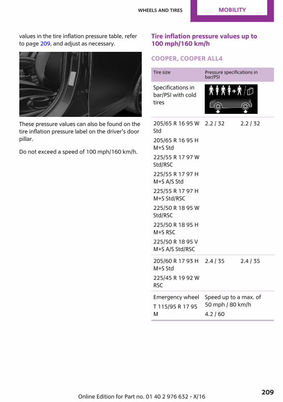
values in the tire inflation pressure table, referto page 209, and adjust as necessary.
These pressure values can also be found on thetire inflation pressure label on the driver's doorpillar.
Do not exceed a speed of 100 mph/160 km/h.
Tire inflation pressure values up to100 mph/160 km/h
COOPER, COOPER ALL4
Tire size Pressure specifications inbar/PSI
Specifications inbar/PSI with coldtires
205/65 R 16 95 WStd205/65 R 16 95 HM+S Std225/55 R 17 97 WStd/RSC225/55 R 17 97 HM+S A/S Std225/55 R 17 97 HM+S Std/RSC225/50 R 18 95 WStd/RSC225/50 R 18 95 HM+S RSC225/50 R 18 95 VM+S A/S Std/RSC
2.2 / 32 2.2 / 32
205/60 R 17 93 HM+S Std225/45 R 19 92 WRSC
2.4 / 35 2.4 / 35
Emergency wheelT 115/95 R 17 95M
Speed up to a max. of50 mph / 80 km/h4.2 / 60
Seite 209
Wheels and tires MOBILITY
209Online Edition for Part no. 01 40 2 976 632 - X/16
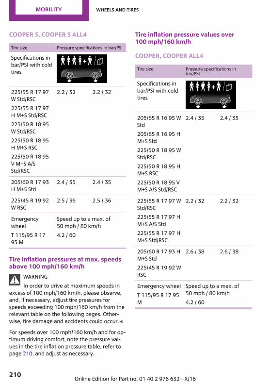
COOPER S, COOPER S ALL4
Tire size Pressure specifications in bar/PSI
Specifications inbar/PSI with coldtires
225/55 R 17 97W Std/RSC225/55 R 17 97H M+S Std/RSC225/50 R 18 95W Std/RSC225/50 R 18 95H M+S RSC225/50 R 18 95V M+S A/SStd/RSC
2.2 / 32 2.2 / 32
205/60 R 17 93H M+S Std
2.4 / 35 2.4 / 35
225/45 R 19 92W RSC
2.5 / 36 2.5 / 36
EmergencywheelT 115/95 R 1795 M
Speed up to a max. of50 mph / 80 km/h4.2 / 60
Tire inflation pressures at max. speedsabove 100 mph/160 km/h
WARNINGIn order to drive at maximum speeds in
excess of 100 mph/160 km/h, please observe,and, if necessary, adjust tire pressures forspeeds exceeding 100 mph/160 km/h from therelevant table on the following pages. Other‐wise, tire damage and accidents could occur.◀
For speeds over 100 mph/160 km/h and for op‐timum driving comfort, note the pressure val‐ues in the tire inflation pressure table, refer topage 210, and adjust as necessary.
Tire inflation pressure values over100 mph/160 km/h
COOPER, COOPER ALL4
Tire size Pressure specifications inbar/PSI
Specifications inbar/PSI with coldtires
205/65 R 16 95 WStd205/65 R 16 95 HM+S Std225/50 R 18 95 WStd/RSC225/50 R 18 95 HM+S RSC225/50 R 18 95 VM+S A/S Std/RSC
2.4 / 35 2.4 / 35
225/55 R 17 97 WStd/RSC225/55 R 17 97 HM+S A/S Std225/55 R 17 97 HM+S Std/RSC
2.2 / 32 2.2 / 32
205/60 R 17 93 HM+S Std225/45 R 19 92 WRSC
2.6 / 38 2.6 / 38
Emergency wheelT 115/95 R 17 95M
Speed up to a max. of50 mph / 80 km/h4.2 / 60
Seite 210
MOBILITY Wheels and tires
210 Online Edition for Part no. 01 40 2 976 632 - X/16
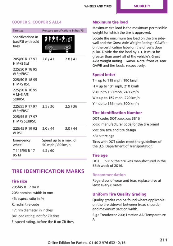
COOPER S, COOPER S ALL4
Tire size Pressure specifications in bar/PSI
Specifications inbar/PSI with coldtires
205/60 R 17 93H M+S Std225/50 R 18 95W Std/RSC225/50 R 18 95H M+S RSC225/50 R 18 95V M+S A/SStd/RSC
2.8 / 41 2.8 / 41
225/55 R 17 97W Std/RSC225/55 R 17 97H M+S Std/RSC
2.5 / 36 2.5 / 36
225/45 R 19 92W RSC
3.0 / 44 3.0 / 44
EmergencywheelT 115/95 R 1795 M
Speed up to a max. of50 mph / 80 km/h4.2 / 60
Tire identification marksTire size205/45 R 17 84 V205: nominal width in mm45: aspect ratio in %R: radial tire code17: rim diameter in inches84: load rating, not for ZR tiresF: speed rating, before the R on ZR tires
Maximum tire loadMaximum tire load is the maximum permissibleweight for which the tire is approved.Locate the maximum tire load on the tire side‐wall and the Gross Axle Weight Rating – GAWR –on the certification label on the driver’s doorpillar. Divide the tire load by 1.1. It must begreater than one-half of the vehicle’s GrossAxle Weight Rating – GAWR. Note, front vs. rearGAWR and tire loads, respectively.
Speed letterT = up to 118 mph, 190 km/hH = up to 131 mph, 210 km/hV = up to 150 mph, 240 km/hW = up to 167 mph, 270 km/hY = up to 186 mph, 300 km/h
Tire Identification NumberDOT code: DOT xxxx xxx 3816xxxx: manufacturer code for the tire brandxxx: tire size and tire design3816: tire ageTires with DOT codes meet the guidelines ofthe U.S. Department of Transportation.
Tire ageDOT … 3816: the tire was manufactured in the38th week of 2016.
RecommendationRegardless of wear and tear, replace tires atleast every 6 years.
Uniform Tire Quality GradingQuality grades can be found where applicableon the tire sidewall between tread shoulderand maximum section width.E.g.: Treadwear 200; Traction AA; TemperatureA
Seite 211
Wheels and tires MOBILITY
211Online Edition for Part no. 01 40 2 976 632 - X/16
DOT Quality GradesTreadwearTraction AA A B CTemperature A B CAll passenger vehicle tires must conform toFederal Safety Requirements in addition tothese grades.
TreadwearThe treadwear grade is a comparative ratingbased on the wear rate of the tire when testedunder controlled conditions on a specified gov‐ernment test course. E.g., a tire graded 150would wear one and one-half, 1 g, times as wellon the government course as a tire graded 100.The relative performance of tires depends uponthe actual conditions of their use, however, andmay depart significantly from the norm due tovariations in driving habits, service practicesand differences in road characteristics and cli‐mate.
TractionThe traction grades, from highest to lowest, areAA, A, B, and C.Those grades represent the tire's ability to stopon wet pavement as measured under control‐led conditions on specified government testsurfaces of asphalt and concrete. A tire markedC may have poor traction performance.The traction grade assigned to this tire is basedon straight-ahead braking traction tests, anddoes not include acceleration, cornering, hy‐droplaning, or peak traction characteristics.
TemperatureThe temperature grades are A, the highest, B,and C, representing the tire's resistance to thegeneration of heat and its ability to dissipateheat when tested under controlled conditionson a specified indoor laboratory test wheel.Sustained high temperature can cause the ma‐terial of the tire to degenerate and reduce tirelife, and excessive temperature can lead to
sudden tire failure. The grade C corresponds toa level of performance which all passenger ve‐hicle tires must meet under the Federal MotorVehicle Safety Standard No. 109. Grades Band Arepresent higher levels of performance on thelaboratory test wheel than the minimum re‐quired by law.
WARNINGThe temperature grade for this tire is es‐
tablished for a tire that is properly inflated andnot overloaded. Excessive speed, underinfla‐tion, or excessive loading, either separately orin combination, can cause heat buildup andpossible tire failure.◀
RSC – Run-flat tiresRun-flat tires, refer to page 215, are labeledwith a circular symbol containing the lettersRSC marked on the sidewall.
M+SWinter and all-season tires with better coldweather performance than summer tires.
Tire treadSummer tiresDo not drive with a tire tread depth of less than0.12 in/3 mm.There is an increased risk of hydroplaning if thetire tread depth is less than 0.12 inches/3 mm.
Winter tiresDo not drive with a tire tread depth of less than0.16 inches/4 mm.Below a tread depth of 0.16 inches/4 mm, tiresare less suitable for winter operation.
Seite 212
MOBILITY Wheels and tires
212 Online Edition for Part no. 01 40 2 976 632 - X/16

Minimum tread depth
Wear indicators are distributed around the tire'scircumference and have the legally requiredminimum height of 0.063 inches/1.6 mm.
They are marked on the side of the tire withTWI, Tread Wear Indicator.
Tire damageGeneral informationInspect your tires regularly for damage, foreignobjects lodged in the tread, and tread wear.Driving over rough or damaged road surfaces,as well as debris, curbs and other obstacles cancause serious damage to wheels, tires and sus‐pension parts. This is more likely to occur withlow-profile tires, which provide less cushioningbetween the wheel and the road. Be careful toavoid road hazards and reduce your speed, es‐pecially if your vehicle is equipped with low-profile tires.Indications of tire damage or other vehicle mal‐functions:▷ Unusual vibrations while driving.▷ Unusual handling such as a strong ten‐
dency to pull to the left or right.Damage can, e.g., be caused by driving overcurbs, road damage, or similar things.
Safety informationWARNINGDamaged tires can lose tire inflation pres‐
sure, which can lead to loss of vehicle control.There is a risk of an accident. If tire damage issuspected while driving, immediately reducespeed and stop. Have wheels and tireschecked. For this purpose, drive carefully to thenearest dealer’s service center or anotherqualified service center or repair shop. Havevehicle towed or transported as needed.◀
WARNINGDamaged tires can lose tire inflation pres‐
sure, which can lead to loss of vehicle control.There is a risk of an accident. Do not repairdamaged tires, but have them replaced.◀
Changing wheels andtiresMountingHave mounting and wheel balancing carriedout by a dealer’s service center or anotherqualified service center or repair shop.
Wheel and tire combination
General informationYou can ask the dealer’s service center or an‐other qualified service center or repair shopabout the correct wheel/tire combination andwheel rim versions for the vehicle.Incorrect wheel and tire combinations impairthe function of a variety of systems such as ABSor DSC.To maintain good handling and vehicle re‐sponse, use only tires with a single tread con‐figuration from a single manufacturer.Following tire damage, have the original wheeland tire combination remounted on the vehicleas soon as possible.
Seite 213
Wheels and tires MOBILITY
213Online Edition for Part no. 01 40 2 976 632 - X/16
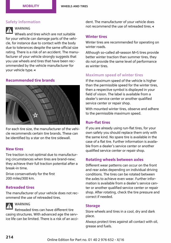
Safety informationWARNINGWheels and tires which are not suitable
for your vehicle can damage parts of the vehi‐cle, for instance due to contact with the bodydue to tolerances despite the same official sizerating. There is a risk of an accident. The manu‐facturer of your vehicle strongly suggests thatyou use wheels and tires that have been rec‐ommended by the vehicle manufacturer foryour vehicle type.◀
Recommended tire brands
For each tire size, the manufacturer of the vehi‐cle recommends certain tire brands. These canbe identified by a star on the tire sidewall.
New tiresTire traction is not optimal due to manufactur‐ing circumstances when tires are brand-new;they achieve their full traction potential after abreak-in time.Drive conservatively for the first200 miles/300 km.
Retreaded tiresThe manufacturer of your vehicle does not rec‐ommend the use of retreaded tires.
WARNINGRetreaded tires can have different tire
casing structures. With advanced age the serv‐ice life can be limited. There is a risk of an acci‐
dent. The manufacturer of your vehicle doesnot recommend the use of retreaded tires.◀
Winter tiresWinter tires are recommended for operating onwinter roads.Although so-called all-season M+S tires providebetter winter traction than summer tires, theydo not provide the same level of performanceas winter tires.
Maximum speed of winter tiresIf the maximum speed of the vehicle is higherthan the permissible speed for the winter tires,then a respective symbol is displayed in yourfield of vision. The label is available from adealer’s service center or another qualifiedservice center or repair shop.With mounted winter tires, observe and adhereto the permissible maximum speed.
Run-flat tiresIf you are already using run-flat tires, for yourown safety you should replace them only withthe same kind. No spare tire is available in thecase of a flat tire. Further information is availa‐ble from a dealer’s service center or anotherqualified service center or repair shop.
Rotating wheels between axlesDifferent wear patterns can occur on the frontand rear axles depending on individual drivingconditions. The tires can be rotated betweenthe axles to achieve even wear. Further infor‐mation is available from a dealer’s service cen‐ter or another qualified service center or repairshop. After rotating, check the tire pressure andcorrect if needed.
StorageStore wheels and tires in a cool, dry and darkplace.Always protect tires against all contact with oil,grease and fuels.
Seite 214
MOBILITY Wheels and tires
214 Online Edition for Part no. 01 40 2 976 632 - X/16
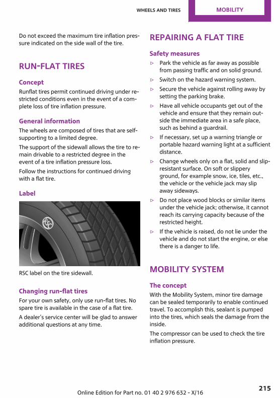
Do not exceed the maximum tire inflation pres‐sure indicated on the side wall of the tire.
Run-flat tiresConceptRunflat tires permit continued driving under re‐stricted conditions even in the event of a com‐plete loss of tire inflation pressure.
General informationThe wheels are composed of tires that are self-supporting to a limited degree.The support of the sidewall allows the tire to re‐main drivable to a restricted degree in theevent of a tire inflation pressure loss.Follow the instructions for continued drivingwith a flat tire.
Label
RSC label on the tire sidewall.
Changing run-flat tiresFor your own safety, only use run-flat tires. Nospare tire is available in the case of a flat tire.A dealer’s service center will be glad to answeradditional questions at any time.
Repairing a flat tireSafety measures▷ Park the vehicle as far away as possible
from passing traffic and on solid ground.▷ Switch on the hazard warning system.▷ Secure the vehicle against rolling away by
setting the parking brake.▷ Have all vehicle occupants get out of the
vehicle and ensure that they remain out‐side the immediate area in a safe place,such as behind a guardrail.
▷ If necessary, set up a warning triangle orportable hazard warning light at a sufficientdistance.
▷ Change wheels only on a flat, solid and slip-resistant surface. On soft or slipperyground, for example snow, ice, tiles, etc.,the vehicle or the vehicle jack may slipaway sideways.
▷ Do not place wood blocks or similar itemsunder the vehicle jack; otherwise, it cannotreach its carrying capacity because of therestricted height.
▷ If the vehicle is raised, do not lie under thevehicle and do not start the engine, or elsethere is a danger to life.
Mobility SystemThe conceptWith the Mobility System, minor tire damagecan be sealed temporarily to enable continuedtravel. To accomplish this, sealant is pumpedinto the tires, which seals the damage from theinside.The compressor can be used to check the tireinflation pressure.
Seite 215
Wheels and tires MOBILITY
215Online Edition for Part no. 01 40 2 976 632 - X/16
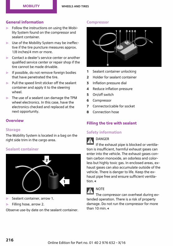
General information▷ Follow the instructions on using the Mobi‐
lity System found on the compressor andsealant container.
▷ Use of the Mobility System may be ineffec‐tive if the tire puncture measures approx.1/8 inches/4 mm or more.
▷ Contact a dealer’s service center or anotherqualified service center or repair shop if thetire cannot be made drivable.
▷ If possible, do not remove foreign bodiesthat have penetrated the tire.
▷ Pull the speed limit sticker off the sealantcontainer and apply it to the steeringwheel.
▷ The use of a sealant can damage the TPMwheel electronics. In this case, have theelectronics checked and replaced at thenext opportunity.
Overview
StorageThe Mobility System is located in a bag on theright side trim in the cargo area.
Sealant container
▷ Sealant container, arrow 1.▷ Filling hose, arrow 2.Observe use-by date on the sealant container.
Compressor
1 Sealant container unlocking2 Holder for sealant container3 Inflation pressure dial4 Reduce inflation pressure5 On/off switch6 Compressor7 Connector/cable for socket8 Connection hose
Filling the tire with sealant
Safety informationDANGERIf the exhaust pipe is blocked or ventila‐
tion is insufficient, harmful exhaust gases canenter into the vehicle. The exhaust gases con‐tain carbon monoxide, an odorless and color‐less but highly toxic gas. In enclosed areas, ex‐haust gases can also accumulate outside of thevehicle. There is danger to life. Keep the ex‐haust pipe free and ensure sufficient ventila‐tion.◀
NOTEThe compressor can overheat during ex‐
tended operation. There is a risk of propertydamage. Do not run the compressor for morethan 10 min.◀
Seite 216
MOBILITY Wheels and tires
216 Online Edition for Part no. 01 40 2 976 632 - X/16
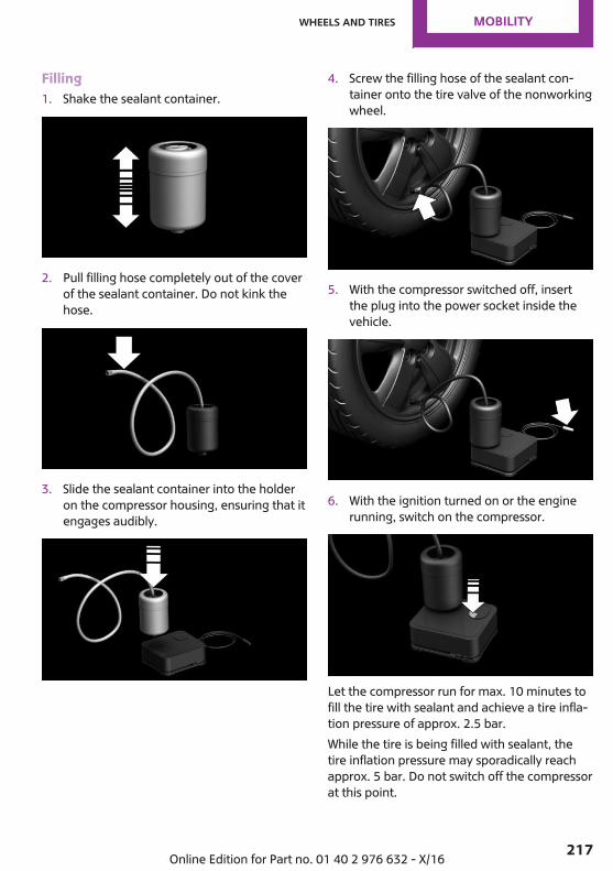
Filling1. Shake the sealant container.
2. Pull filling hose completely out of the coverof the sealant container. Do not kink thehose.
3. Slide the sealant container into the holderon the compressor housing, ensuring that itengages audibly.
4. Screw the filling hose of the sealant con‐tainer onto the tire valve of the nonworkingwheel.
5. With the compressor switched off, insertthe plug into the power socket inside thevehicle.
6. With the ignition turned on or the enginerunning, switch on the compressor.
Let the compressor run for max. 10 minutes tofill the tire with sealant and achieve a tire infla‐tion pressure of approx. 2.5 bar.While the tire is being filled with sealant, thetire inflation pressure may sporadically reachapprox. 5 bar. Do not switch off the compressorat this point.
Seite 217
Wheels and tires MOBILITY
217Online Edition for Part no. 01 40 2 976 632 - X/16
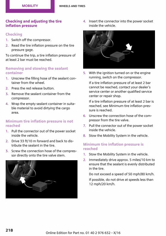
Checking and adjusting the tireinflation pressure
Checking1. Switch off the compressor.2. Read the tire inflation pressure on the tire
pressure gage.To continue the trip, a tire inflation pressure ofat least 2 bar must be reached.
Removing and stowing the sealantcontainer1. Unscrew the filling hose of the sealant con‐
tainer from the wheel.2. Press the red release button.3. Remove the sealant container from the
compressor.4. Wrap the empty sealant container in suita‐
ble material to avoid dirtying the cargoarea.
Minimum tire inflation pressure is notreached1. Pull the connector out of the power socket
inside the vehicle.2. Drive 33 ft/10 m forward and back to dis‐
tribute the sealant in the tire.3. Screw the connection hose of the compres‐
sor directly onto the tire valve stem.
4. Insert the connector into the power socketinside the vehicle.
5. With the ignition turned on or the enginerunning, switch on the compressor.If a tire inflation pressure of at least 2 barcannot be reached, contact your dealer’sservice center or another qualified servicecenter or repair shop.If a tire inflation pressure of at least 2 bar isreached, see Minimum tire inflation pres‐sure is reached.
6. Unscrew the connection hose of the com‐pressor from the tire valve.
7. Pull the connector out of the power socketinside the vehicle.
8. Stow the Mobility System in the vehicle.
Minimum tire inflation pressure isreached1. Stow the Mobility System in the vehicle.2. Immediately drive approx. 5 miles/10 km to
ensure that the sealant is evenly distributedin the tire.Do not exceed a speed of 50 mph/80 km/h.If possible, do not drive at speeds less than12 mph/20 km/h.
Seite 218
MOBILITY Wheels and tires
218 Online Edition for Part no. 01 40 2 976 632 - X/16
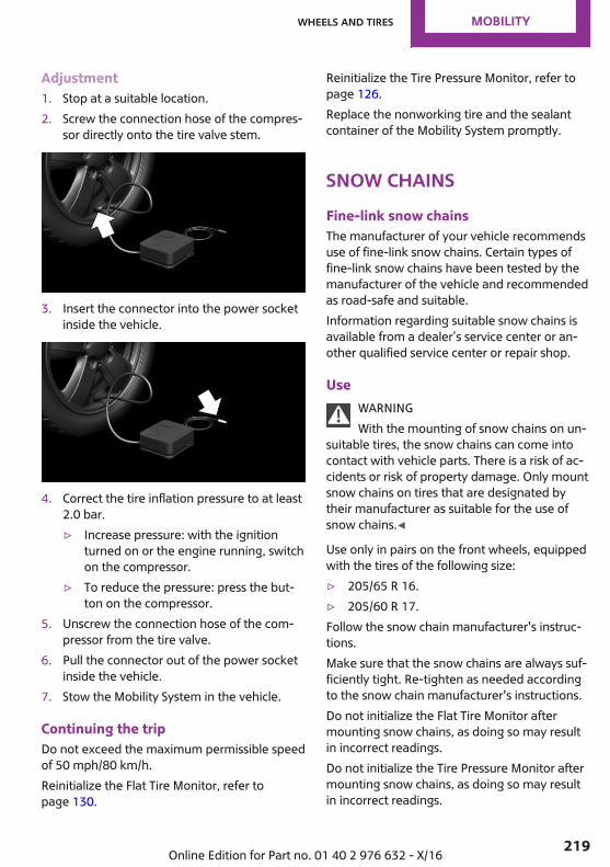
Adjustment1. Stop at a suitable location.2. Screw the connection hose of the compres‐
sor directly onto the tire valve stem.
3. Insert the connector into the power socketinside the vehicle.
4. Correct the tire inflation pressure to at least2.0 bar.▷ Increase pressure: with the ignition
turned on or the engine running, switchon the compressor.
▷ To reduce the pressure: press the but‐ton on the compressor.
5. Unscrew the connection hose of the com‐pressor from the tire valve.
6. Pull the connector out of the power socketinside the vehicle.
7. Stow the Mobility System in the vehicle.
Continuing the tripDo not exceed the maximum permissible speedof 50 mph/80 km/h.Reinitialize the Flat Tire Monitor, refer topage 130.
Reinitialize the Tire Pressure Monitor, refer topage 126.Replace the nonworking tire and the sealantcontainer of the Mobility System promptly.
Snow chainsFine-link snow chainsThe manufacturer of your vehicle recommendsuse of fine-link snow chains. Certain types offine-link snow chains have been tested by themanufacturer of the vehicle and recommendedas road-safe and suitable.Information regarding suitable snow chains isavailable from a dealer’s service center or an‐other qualified service center or repair shop.
UseWARNINGWith the mounting of snow chains on un‐
suitable tires, the snow chains can come intocontact with vehicle parts. There is a risk of ac‐cidents or risk of property damage. Only mountsnow chains on tires that are designated bytheir manufacturer as suitable for the use ofsnow chains.◀
Use only in pairs on the front wheels, equippedwith the tires of the following size:▷ 205/65 R 16.▷ 205/60 R 17.Follow the snow chain manufacturer's instruc‐tions.Make sure that the snow chains are always suf‐ficiently tight. Re-tighten as needed accordingto the snow chain manufacturer's instructions.Do not initialize the Flat Tire Monitor aftermounting snow chains, as doing so may resultin incorrect readings.Do not initialize the Tire Pressure Monitor aftermounting snow chains, as doing so may resultin incorrect readings.
Seite 219
Wheels and tires MOBILITY
219Online Edition for Part no. 01 40 2 976 632 - X/16
When driving with snow chains, briefly activateDynamic Traction Control, if needed.
Maximum speed with snow chainsDo not exceed a speed of 30 mph/50 km/hwhen using snow chains.
Changing wheels/tiresGeneral informationWhen using runflat tires or tire sealants, a tiredoes not always need to be changed immedi‐ately in the event of pressure loss due to a flattire.If needed, the tools for changing wheels areavailable as accessories from a dealer’s servicecenter or another qualified service center or re‐pair shop.
Safety informationWARNINGThe jack, issued by the vehicle manufac‐
turer, is provided in order to perform a wheelchange in the event of a breakdown. The jack isnot designed for frequent use; for example,changing from summer to winter tires.. Usingthe jack frequently may cause it to becomejammed or damaged. There is a risk of injuryand risk of damage to property. Only use thejack to attach an emergency or spare wheel inthe event of a breakdown.◀
WARNINGOn soft or slippery ground, e.g., snow, ice,
tiles, etc., the vehicle jack can slip away. Thereis a risk of injury. If possible, change the tire/wheel on a flat, solid and slip-resistant sur‐face.◀
WARNINGThe vehicle jack is only provided for
short-term lifting of the vehicle for wheelchanges. Even if all safety measures are ob‐
served, there is a risk of the raised vehicle fall‐ing, if the vehicle jack tilts over. There is a riskof injuries or danger to life. If the vehicle israised, do not lie under the vehicle and do notstart the engine.◀
WARNINGThe vehicle jack is optimized for lifting
the vehicle and for the jacking points on the ve‐hicle only. There is a risk of injury. Do not liftany other vehicle or cargo using the vehiclejack.◀
WARNINGIf the vehicle jack is not inserted into the
jacking point provided for this purpose, the ve‐hicle may be damaged or the vehicle jack mayslip when it is being cranked up. There is a riskof injury or risk of damage to property. Whencranking up the vehicle jack, ensure that it is in‐serted in the jacking point next to the wheelhousing.◀
WARNINGA vehicle that is raised on a vehicle jack
may fall off of the jack if lateral forces are ex‐erted on it. There is a risk of injury and risk ofdamage to property. While the vehicle is raised,do not exert lateral forces on the vehicle or pullabruptly on the vehicle. Have a stuck wheel re‐moved by a dealer’s service center or anotherqualified service center or repair shop.◀
Securing the vehicle against rolling
General informationThe vehicle manufacturer recommends to addi‐tionally secure the vehicle against rolling awaywhen changing a wheel.
Seite 220
MOBILITY Wheels and tires
220 Online Edition for Part no. 01 40 2 976 632 - X/16
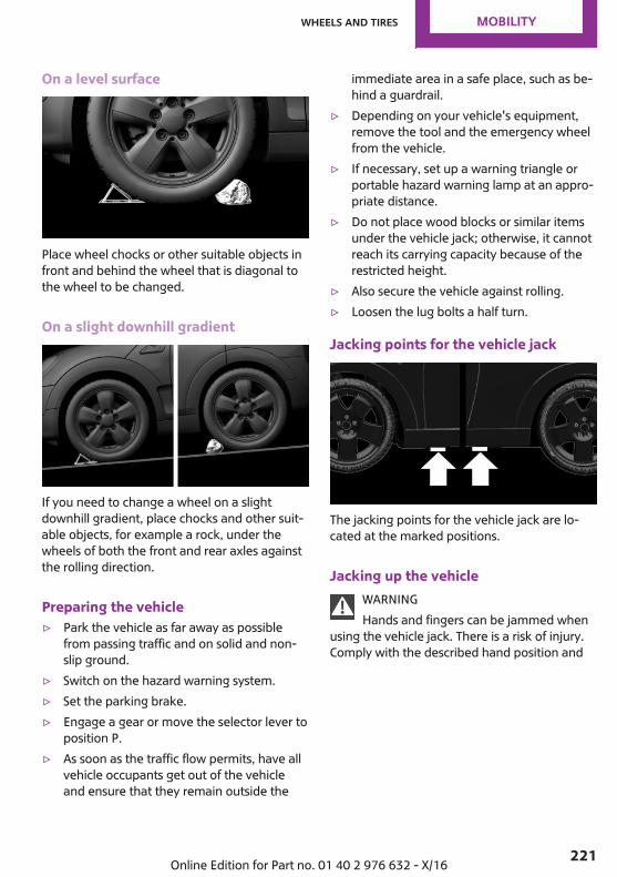
On a level surface
Place wheel chocks or other suitable objects infront and behind the wheel that is diagonal tothe wheel to be changed.
On a slight downhill gradient
If you need to change a wheel on a slightdownhill gradient, place chocks and other suit‐able objects, for example a rock, under thewheels of both the front and rear axles againstthe rolling direction.
Preparing the vehicle▷ Park the vehicle as far away as possible
from passing traffic and on solid and non-slip ground.
▷ Switch on the hazard warning system.▷ Set the parking brake.▷ Engage a gear or move the selector lever to
position P.▷ As soon as the traffic flow permits, have all
vehicle occupants get out of the vehicleand ensure that they remain outside the
immediate area in a safe place, such as be‐hind a guardrail.
▷ Depending on your vehicle's equipment,remove the tool and the emergency wheelfrom the vehicle.
▷ If necessary, set up a warning triangle orportable hazard warning lamp at an appro‐priate distance.
▷ Do not place wood blocks or similar itemsunder the vehicle jack; otherwise, it cannotreach its carrying capacity because of therestricted height.
▷ Also secure the vehicle against rolling.▷ Loosen the lug bolts a half turn.
Jacking points for the vehicle jack
The jacking points for the vehicle jack are lo‐cated at the marked positions.
Jacking up the vehicleWARNINGHands and fingers can be jammed when
using the vehicle jack. There is a risk of injury.Comply with the described hand position and
Seite 221
Wheels and tires MOBILITY
221Online Edition for Part no. 01 40 2 976 632 - X/16
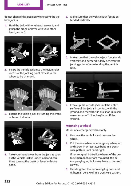
do not change this position while using the ve‐hicle jack.◀
1. Hold the jack with one hand, arrow 1, andgrasp the crank or lever with your otherhand, arrow 2.
2. Insert the vehicle jack into the rectangularrecess of the jacking point closest to thewheel to be changed.
3. Extend the vehicle jack by turning the crankor lever clockwise.
4. Take your hand away from the jack as soonas the vehicle jack is under load and con‐tinue turning the crank or lever with onehand.
5. Make sure that the vehicle jack foot is ex‐tended vertically.
6. Make sure that the vehicle jack foot standsvertically and perpendicularly beneath thejacking point after extending the vehiclejack.
7. Crank up the vehicle jack until the entiresurface of the jack is in contact with theground and the wheel in question is raiseda maximum of 1.2 inches/3 cm off theground.
Mounting a wheelMount one emergency wheel only.
1. Unscrew the lug bolts and remove thewheel.
2. Put the new wheel or emergency wheel onand screw in at least two bolts in a cross‐wise pattern until hand-tight.If non-original light-alloy wheels of the ve‐hicle manufacturer are mounted, the ac‐companying lug bolts may have to be usedas well.
3. Hand-tighten the remaining lug bolts andtighten all bolts well in a crosswise pattern.
Seite 222
MOBILITY Wheels and tires
222 Online Edition for Part no. 01 40 2 976 632 - X/16
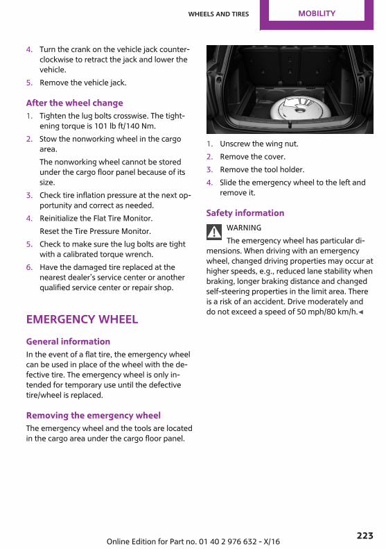
4. Turn the crank on the vehicle jack counter‐clockwise to retract the jack and lower thevehicle.
5. Remove the vehicle jack.
After the wheel change1. Tighten the lug bolts crosswise. The tight‐
ening torque is 101 lb ft/140 Nm.2. Stow the nonworking wheel in the cargo
area.The nonworking wheel cannot be storedunder the cargo floor panel because of itssize.
3. Check tire inflation pressure at the next op‐portunity and correct as needed.
4. Reinitialize the Flat Tire Monitor.Reset the Tire Pressure Monitor.
5. Check to make sure the lug bolts are tightwith a calibrated torque wrench.
6. Have the damaged tire replaced at thenearest dealer’s service center or anotherqualified service center or repair shop.
emergency wheelGeneral informationIn the event of a flat tire, the emergency wheelcan be used in place of the wheel with the de‐fective tire. The emergency wheel is only in‐tended for temporary use until the defectivetire/wheel is replaced.
Removing the emergency wheelThe emergency wheel and the tools are locatedin the cargo area under the cargo floor panel.
1. Unscrew the wing nut.2. Remove the cover.3. Remove the tool holder.4. Slide the emergency wheel to the left and
remove it.
Safety informationWARNINGThe emergency wheel has particular di‐
mensions. When driving with an emergencywheel, changed driving properties may occur athigher speeds, e.g., reduced lane stability whenbraking, longer braking distance and changedself-steering properties in the limit area. Thereis a risk of an accident. Drive moderately anddo not exceed a speed of 50 mph/80 km/h.◀
Seite 223
Wheels and tires MOBILITY
223Online Edition for Part no. 01 40 2 976 632 - X/16
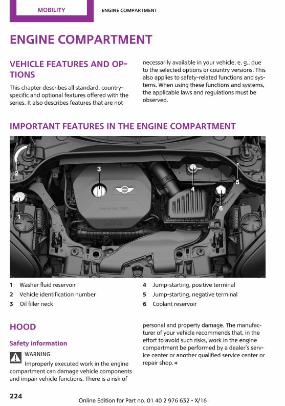
Engine compartmentVehicle features and op‐tionsThis chapter describes all standard, country-specific and optional features offered with theseries. It also describes features that are not
necessarily available in your vehicle, e. g., dueto the selected options or country versions. Thisalso applies to safety-related functions and sys‐tems. When using these functions and systems,the applicable laws and regulations must beobserved.
Important features in the engine compartment
1 Washer fluid reservoir2 Vehicle identification number3 Oil filler neck
4 Jump-starting, positive terminal5 Jump-starting, negative terminal6 Coolant reservoir
HoodSafety information
WARNINGImproperly executed work in the engine
compartment can damage vehicle componentsand impair vehicle functions. There is a risk of
personal and property damage. The manufac‐turer of your vehicle recommends that, in theeffort to avoid such risks, work in the enginecompartment be performed by a dealer’s serv‐ice center or another qualified service center orrepair shop.◀
Seite 224
MOBILITY Engine compartment
224 Online Edition for Part no. 01 40 2 976 632 - X/16
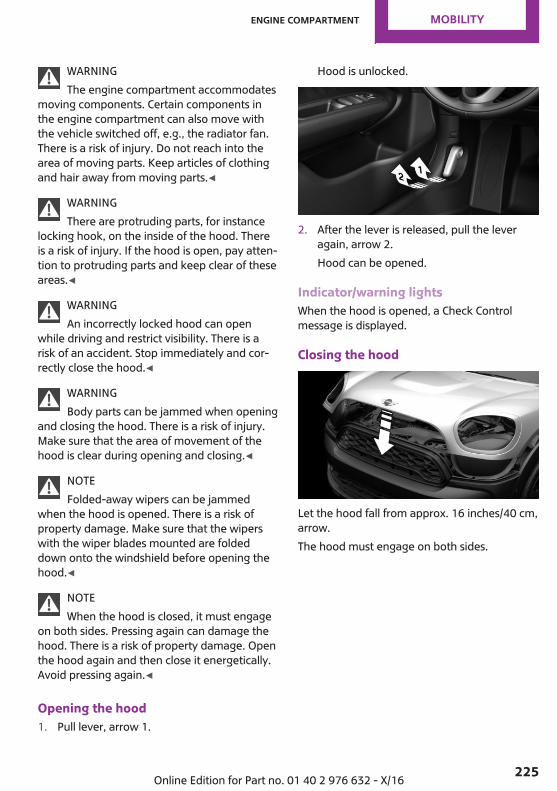
WARNINGThe engine compartment accommodates
moving components. Certain components inthe engine compartment can also move withthe vehicle switched off, e.g., the radiator fan.There is a risk of injury. Do not reach into thearea of moving parts. Keep articles of clothingand hair away from moving parts.◀
WARNINGThere are protruding parts, for instance
locking hook, on the inside of the hood. Thereis a risk of injury. If the hood is open, pay atten‐tion to protruding parts and keep clear of theseareas.◀
WARNINGAn incorrectly locked hood can open
while driving and restrict visibility. There is arisk of an accident. Stop immediately and cor‐rectly close the hood.◀
WARNINGBody parts can be jammed when opening
and closing the hood. There is a risk of injury.Make sure that the area of movement of thehood is clear during opening and closing.◀
NOTEFolded-away wipers can be jammed
when the hood is opened. There is a risk ofproperty damage. Make sure that the wiperswith the wiper blades mounted are foldeddown onto the windshield before opening thehood.◀
NOTEWhen the hood is closed, it must engage
on both sides. Pressing again can damage thehood. There is a risk of property damage. Openthe hood again and then close it energetically.Avoid pressing again.◀
Opening the hood1. Pull lever, arrow 1.
Hood is unlocked.
2. After the lever is released, pull the leveragain, arrow 2.Hood can be opened.
Indicator/warning lightsWhen the hood is opened, a Check Controlmessage is displayed.
Closing the hood
Let the hood fall from approx. 16 inches/40 cm,arrow.The hood must engage on both sides.
Seite 225
Engine compartment MOBILITY
225Online Edition for Part no. 01 40 2 976 632 - X/16
Engine oilVehicle features and op‐tionsThis chapter describes all standard, country-specific and optional features offered with theseries. It also describes features that are notnecessarily available in your vehicle, e. g., dueto the selected options or country versions. Thisalso applies to safety-related functions and sys‐tems. When using these functions and systems,the applicable laws and regulations must beobserved.
General informationThe engine oil consumption is dependent onthe driving style and driving conditions.Therefore, regularly check the engine oil levelafter refueling.The engine oil consumption can increase in thefollowing situations, for example:▷ Sporty driving style.▷ Break-in of the engine.▷ Idling of the engine.▷ With use of engine oil types that are classi‐
fied as not suitable.The vehicle is equipped with electronic oilmeasurement.The electronic oil measurement has two meas‐uring principles:▷ Status display.▷ Detailed measurement.
Electronic oil measure‐mentStatus display
The conceptThe engine oil level is monitored electronicallywhile driving and shown on the Control Display.If the engine oil level reaches the minimumlevel, a check control message is displayed.
Functional requirementsA current measured value is available after ap‐prox. 30 minutes of driving. During a shortertrip, the status of the last, sufficiently long trip isdisplayed.With frequent short-distance trips, perform adetailed measurement.
Displaying the engine oil levelVia the onboard monitor:
1. "My MINI"2. "Vehicle status"3. "Engine oil level"The engine oil level is displayed.
Engine oil level display messagesDifferent messages appear on the display de‐pending on the engine oil level. Pay attentionto these messages.If the engine oil level is too low within the next125 miles/200 km, add engine oil, refer topage 227.
A red indicator light indicates that theengine oil pressure is too high or toolow.
Seite 226
MOBILITY Engine oil
226 Online Edition for Part no. 01 40 2 976 632 - X/16

NOTEAn engine oil level that is too low causes
engine damage. There is a risk of propertydamage. Immediately add engine oil.◀
Take care not to add too much engine oil.NOTEToo much engine oil can damage the en‐
gine or the catalytic converter. There is a risk ofproperty damage. Do not add too much engineoil. When too much engine oil is added, have oillevel corrected by a dealer’s service center oranother qualified service center or repairshop.◀
Detailed measurement
The conceptIn the detailed measurement the engine oillevel is checked when the vehicle is stationary,and displayed via a scale.If the engine oil level reaches the minimumlevel, a check control message is displayed.During the measurement, the idle speed is in‐creased somewhat.
Functional requirements▷ Vehicle is parked in a horizontal position.▷ Manual transmission: shift lever in neutral
position, clutch and accelerator pedals notdepressed.
▷ Steptronic transmission: selector lever in se‐lector lever position N or P and acceleratorpedal not depressed.
▷ Engine is running and is at operating tem‐perature.
Performing a detailed measurementVia the onboard monitor:
1. "My MINI"2. "Vehicle status"3. "Engine oil level"
4. "Measure engine oil level"5. "Start measurement"The engine oil level is checked and displayedvia a scale.Time: approx. 1 minute.
Adding engine oilGeneral informationOnly add engine oil when the message is dis‐played in the instrument cluster. The quantityto be added is indicated in the message dis‐played in the instrument cluster.Switch off the ignition and safely park the vehi‐cle before engine oil is added.
Safety informationWARNINGOperating materials, e.g., oils, greases,
coolants, fuels, can contain harmful ingredi‐ents. There is a risk of injuries or danger to life.Observe the instructions on the containers.Avoid the contact of articles of clothing, skin oreyes with operating materials. Do not refill op‐erating materials into different bottles. Storeoperating materials out of reach of children.◀
NOTEAn engine oil level that is too low causes
engine damage. There is a risk of propertydamage.Add engine oil within the next125 miles/200 km.◀
NOTEToo much engine oil can damage the en‐
gine or the catalytic converter. There is a risk ofproperty damage. Do not add too much engineoil. When too much engine oil is added, have oillevel corrected by a dealer’s service center oranother qualified service center or repairshop.◀
Seite 227
Engine oil MOBILITY
227Online Edition for Part no. 01 40 2 976 632 - X/16
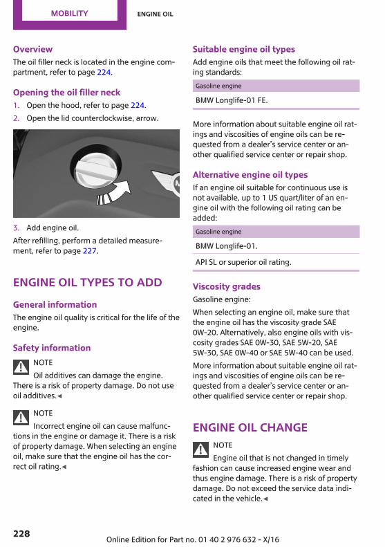
OverviewThe oil filler neck is located in the engine com‐partment, refer to page 224.
Opening the oil filler neck1. Open the hood, refer to page 224.2. Open the lid counterclockwise, arrow.
3. Add engine oil.After refilling, perform a detailed measure‐ment, refer to page 227.
Engine oil types to addGeneral informationThe engine oil quality is critical for the life of theengine.
Safety informationNOTEOil additives can damage the engine.
There is a risk of property damage. Do not useoil additives.◀
NOTEIncorrect engine oil can cause malfunc‐
tions in the engine or damage it. There is a riskof property damage. When selecting an engineoil, make sure that the engine oil has the cor‐rect oil rating.◀
Suitable engine oil typesAdd engine oils that meet the following oil rat‐ing standards:Gasoline engine
BMW Longlife-01 FE.
More information about suitable engine oil rat‐ings and viscosities of engine oils can be re‐quested from a dealer’s service center or an‐other qualified service center or repair shop.
Alternative engine oil typesIf an engine oil suitable for continuous use isnot available, up to 1 US quart/liter of an en‐gine oil with the following oil rating can beadded:Gasoline engine
BMW Longlife-01.
API SL or superior oil rating.
Viscosity gradesGasoline engine:When selecting an engine oil, make sure thatthe engine oil has the viscosity grade SAE0W-20. Alternatively, also engine oils with vis‐cosity grades SAE 0W-30, SAE 5W-20, SAE5W-30, SAE 0W-40 or SAE 5W-40 can be used.More information about suitable engine oil rat‐ings and viscosities of engine oils can be re‐quested from a dealer’s service center or an‐other qualified service center or repair shop.
Engine oil changeNOTEEngine oil that is not changed in timely
fashion can cause increased engine wear andthus engine damage. There is a risk of propertydamage. Do not exceed the service data indi‐cated in the vehicle.◀
Seite 228
MOBILITY Engine oil
228 Online Edition for Part no. 01 40 2 976 632 - X/16

The vehicle manufacturer recommends thatyou have a dealer’s service center or anotherqualified service center or repair shop changethe engine oil.
Seite 229
Engine oil MOBILITY
229Online Edition for Part no. 01 40 2 976 632 - X/16
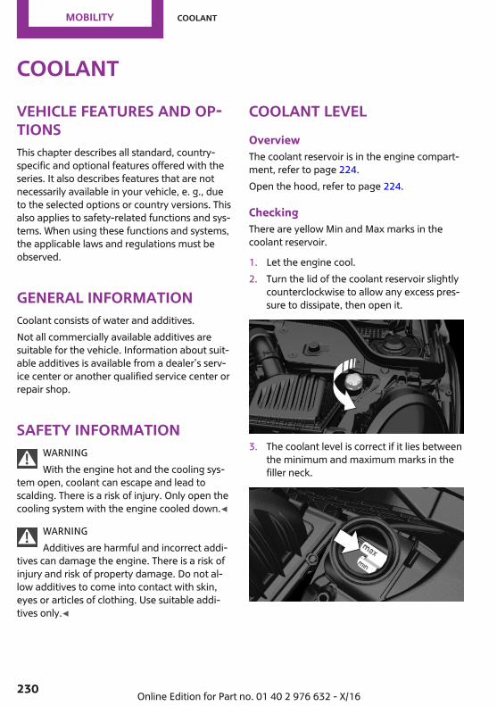
CoolantVehicle features and op‐tionsThis chapter describes all standard, country-specific and optional features offered with theseries. It also describes features that are notnecessarily available in your vehicle, e. g., dueto the selected options or country versions. Thisalso applies to safety-related functions and sys‐tems. When using these functions and systems,the applicable laws and regulations must beobserved.
General informationCoolant consists of water and additives.Not all commercially available additives aresuitable for the vehicle. Information about suit‐able additives is available from a dealer’s serv‐ice center or another qualified service center orrepair shop.
Safety informationWARNINGWith the engine hot and the cooling sys‐
tem open, coolant can escape and lead toscalding. There is a risk of injury. Only open thecooling system with the engine cooled down.◀
WARNINGAdditives are harmful and incorrect addi‐
tives can damage the engine. There is a risk ofinjury and risk of property damage. Do not al‐low additives to come into contact with skin,eyes or articles of clothing. Use suitable addi‐tives only.◀
Coolant levelOverviewThe coolant reservoir is in the engine compart‐ment, refer to page 224.Open the hood, refer to page 224.
CheckingThere are yellow Min and Max marks in thecoolant reservoir.
1. Let the engine cool.2. Turn the lid of the coolant reservoir slightly
counterclockwise to allow any excess pres‐sure to dissipate, then open it.
3. The coolant level is correct if it lies betweenthe minimum and maximum marks in thefiller neck.
Seite 230
MOBILITY Coolant
230 Online Edition for Part no. 01 40 2 976 632 - X/16
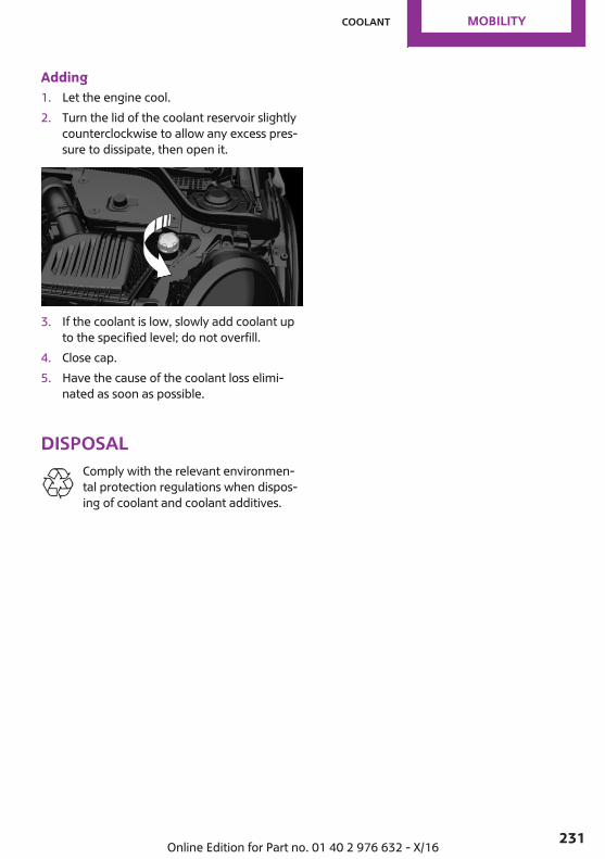
Adding1. Let the engine cool.2. Turn the lid of the coolant reservoir slightly
counterclockwise to allow any excess pres‐sure to dissipate, then open it.
3. If the coolant is low, slowly add coolant upto the specified level; do not overfill.
4. Close cap.5. Have the cause of the coolant loss elimi‐
nated as soon as possible.
DisposalComply with the relevant environmen‐tal protection regulations when dispos‐ing of coolant and coolant additives.
Seite 231
Coolant MOBILITY
231Online Edition for Part no. 01 40 2 976 632 - X/16
MaintenanceVehicle features and op‐tionsThis chapter describes all standard, country-specific and optional features offered with theseries. It also describes features that are notnecessarily available in your vehicle, e. g., dueto the selected options or country versions. Thisalso applies to safety-related functions and sys‐tems. When using these functions and systems,the applicable laws and regulations must beobserved.
MINI maintenance systemThe maintenance system indicates requiredmaintenance measures, and thereby providessupport in maintaining road safety and the op‐erational reliability of the vehicle.In some cases, scopes and intervals may varyaccording to the country-specific version. Re‐placement work, spare parts, fuels and lubri‐cants, and wear materials are calculated sepa‐rately. Further information is available from adealer’s service center or another qualifiedservice center or repair shop.
Condition Based ServiceCBSConceptSensors and special algorithms take into ac‐count the driving conditions of the vehicle. CBSuses these to calculate the need for mainte‐nance.The system makes it possible to adapt theamount of maintenance corresponding to youruser profile.
General informationInformation on service requirements, refer topage 106, can be displayed on the Control Dis‐play.
Service data in the remote controlInformation on the required maintenance iscontinuously stored in the remote control. Thedealer’s service center can read this data outand suggest an optimized maintenance scopefor the vehicle.Therefore, hand the service advisor the remotecontrol with which the vehicle was driven mostrecently.
Storage periodsStorage periods during which the vehicle bat‐tery was disconnected are not taken into ac‐count.If this occurs, have a dealer's service center oranother qualified service center or repair shopupdate the time-dependent maintenance pro‐cedures, such as checking brake fluid and, ifnecessary, changing the engine oil and the mi‐crofilter/activated-charcoal filter.
Service and Warranty In‐formation Booklet forUS models and Warrantyand Service Guide Book‐let for Canadian modelsPlease consult your Service and Warranty Infor‐mation Booklet for US models and Warrantyand Service Guide Booklet for Canadian modelsfor additional information on service require‐ments.The manufacturer of your vehicle recommendsthat maintenance and repair be performed by a
Seite 232
MOBILITY Maintenance
232 Online Edition for Part no. 01 40 2 976 632 - X/16
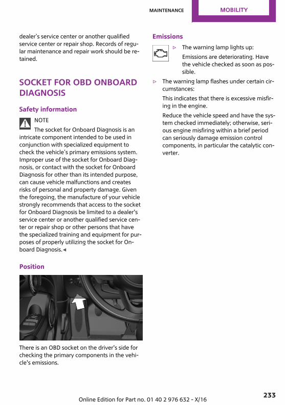
dealer’s service center or another qualifiedservice center or repair shop. Records of regu‐lar maintenance and repair work should be re‐tained.
Socket for OBD OnboardDiagnosisSafety information
NOTEThe socket for Onboard Diagnosis is an
intricate component intended to be used inconjunction with specialized equipment tocheck the vehicle’s primary emissions system.Improper use of the socket for Onboard Diag‐nosis, or contact with the socket for OnboardDiagnosis for other than its intended purpose,can cause vehicle malfunctions and createsrisks of personal and property damage. Giventhe foregoing, the manufacture of your vehiclestrongly recommends that access to the socketfor Onboard Diagnosis be limited to a dealer'sservice center or another qualified service cen‐ter or repair shop or other persons that havethe specialized training and equipment for pur‐poses of properly utilizing the socket for On‐board Diagnosis.◀
Position
There is an OBD socket on the driver's side forchecking the primary components in the vehi‐cle's emissions.
Emissions▷ The warning lamp lights up:
Emissions are deteriorating. Havethe vehicle checked as soon as pos‐sible.
▷ The warning lamp flashes under certain cir‐cumstances:This indicates that there is excessive misfir‐ing in the engine.Reduce the vehicle speed and have the sys‐tem checked immediately; otherwise, seri‐ous engine misfiring within a brief periodcan seriously damage emission controlcomponents, in particular the catalytic con‐verter.
Seite 233
Maintenance MOBILITY
233Online Edition for Part no. 01 40 2 976 632 - X/16
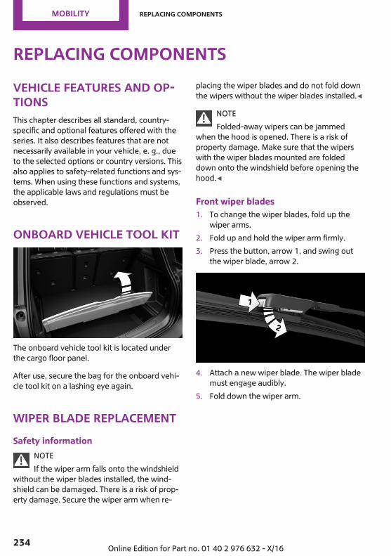
Replacing componentsVehicle features and op‐tionsThis chapter describes all standard, country-specific and optional features offered with theseries. It also describes features that are notnecessarily available in your vehicle, e. g., dueto the selected options or country versions. Thisalso applies to safety-related functions and sys‐tems. When using these functions and systems,the applicable laws and regulations must beobserved.
Onboard vehicle tool kit
The onboard vehicle tool kit is located underthe cargo floor panel.
After use, secure the bag for the onboard vehi‐cle tool kit on a lashing eye again.
Wiper blade replacementSafety information
NOTEIf the wiper arm falls onto the windshield
without the wiper blades installed, the wind‐shield can be damaged. There is a risk of prop‐erty damage. Secure the wiper arm when re‐
placing the wiper blades and do not fold downthe wipers without the wiper blades installed.◀
NOTEFolded-away wipers can be jammed
when the hood is opened. There is a risk ofproperty damage. Make sure that the wiperswith the wiper blades mounted are foldeddown onto the windshield before opening thehood.◀
Front wiper blades1. To change the wiper blades, fold up the
wiper arms.2. Fold up and hold the wiper arm firmly.3. Press the button, arrow 1, and swing out
the wiper blade, arrow 2.
4. Attach a new wiper blade. The wiper blademust engage audibly.
5. Fold down the wiper arm.
Seite 234
MOBILITY Replacing components
234 Online Edition for Part no. 01 40 2 976 632 - X/16
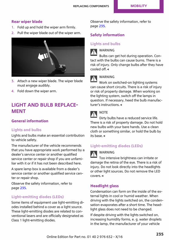
Rear wiper blade1. Fold up and hold the wiper arm firmly.2. Pull the wiper blade out of the wiper arm.
3. Attach a new wiper blade. The wiper blademust engage audibly.
4. Fold down the wiper arm.
Light and bulb replace‐mentGeneral information
Lights and bulbsLights and bulbs make an essential contributionto vehicle safety.The manufacturer of the vehicle recommendsthat you have appropriate work performed by adealer’s service center or another qualifiedservice center or repair shop if you are unfami‐liar with it or if it has not been described here.A spare lamp box is available from a dealer’sservice center or another qualified service cen‐ter or repair shop.Observe the safety information, refer topage 235.
Light-emitting diodes (LEDs)Some items of equipment use light-emitting di‐odes installed behind a cover as a light source.These light-emitting diodes are related to con‐ventional lasers and are officially designated asClass 1 light-emitting diodes.
Observe the safety information, refer topage 235.
Safety information
Lights and bulbsWARNINGBulbs can get hot during operation. Con‐
tact with the bulbs can cause burns. There is arisk of injury. Only change bulbs after they havecooled off.◀
WARNINGWork on switched-on lighting systems
can cause short circuits. There is a risk of injuryor risk of property damage. When working onthe lighting system, switch off the lamps inquestion. If necessary, heed the bulb manufac‐turer's instructions.◀
NOTEDirty bulbs have a reduced service life.
There is a risk of property damage. Do not holdnew bulbs with your bare hands. Use a cleancloth or something similar, or hold the bulb byits base.◀
Light-emitting diodes (LEDs)WARNINGToo intensive brightness can irritate or
damage the retina of the eye. There is a risk ofinjury. Do not look directly into the headlightsor other light sources. Do not remove the LEDcovers.◀
Headlight glassCondensation can form on the inside of the ex‐ternal lights in cool or humid weather. Whendriving with the lights switched on, the conden‐sation evaporates after a short time. The head‐light glass does not need to be changed.If despite driving with the lights switched on,increasing humidity forms, e. g. water dropletsin the lamp, the manufacturer of your vehicle
Seite 235
Replacing components MOBILITY
235Online Edition for Part no. 01 40 2 976 632 - X/16
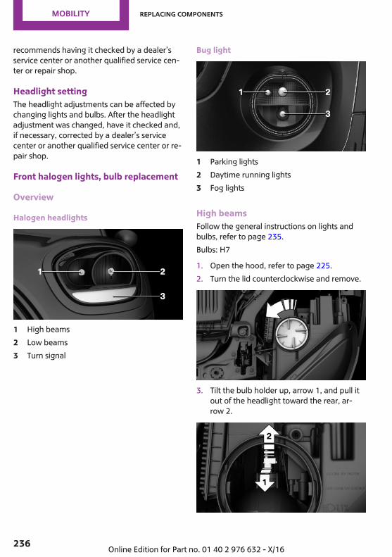
recommends having it checked by a dealer’sservice center or another qualified service cen‐ter or repair shop.
Headlight settingThe headlight adjustments can be affected bychanging lights and bulbs. After the headlightadjustment was changed, have it checked and,if necessary, corrected by a dealer’s servicecenter or another qualified service center or re‐pair shop.
Front halogen lights, bulb replacement
Overview
Halogen headlights
1 High beams2 Low beams3 Turn signal
Bug light
1 Parking lights2 Daytime running lights3 Fog lights
High beamsFollow the general instructions on lights andbulbs, refer to page 235.Bulbs: H7
1. Open the hood, refer to page 225.2. Turn the lid counterclockwise and remove.
3. Tilt the bulb holder up, arrow 1, and pull itout of the headlight toward the rear, ar‐row 2.
Seite 236
MOBILITY Replacing components
236 Online Edition for Part no. 01 40 2 976 632 - X/16

4. Pull the bulb out of the bulb holder.5. Install the new bulb with the bulb holder in
reverse order of removal. In doing so, en‐sure that the bulb tab is correctly posi‐tioned in the headlight housing and thebulb holder perceptibly engages.
6. Check the position of the bulb through theheadlight glass.
7. Close the headlight housing with the lid.Make sure that the lid engages.
Low beamsFollow the general instructions on lights andbulbs, refer to page 235.Bulbs: H7
1. Turn the steering wheel.2. Turn the cover counterclockwise, and re‐
move it.
3. Unscrew the inner lid counterclockwise,and remove it.
4. Tilt the bulb holder down, arrow 1, and pullit downward out of the headlight, arrow 2.
5. Pull the bulb out of the bulb holder.6. Install the new bulb with the bulb holder in
reverse order of removal. In doing so, en‐sure that the bulb tab is correctly posi‐tioned in the headlight housing and thebulb holder perceptibly engages.
7. Check the position of the bulb through theheadlight glass.
8. Install the covers. Make sure that the coversengage.
Turn signalFollow the general instructions on lights andbulbs, refer to page 235.Bulbs: PWY24W
1. Turn the steering wheel.2. Turn the cover counterclockwise, and re‐
move it.
Seite 237
Replacing components MOBILITY
237Online Edition for Part no. 01 40 2 976 632 - X/16

3. Unscrew the inner lid counterclockwise,and remove it.
4. Turn the bulb holder counterclockwise, ar‐row 1, and remove, arrow 2.
5. Press the bulb gently into the bulb holder,turn counterclockwise and remove.
6. Insert the new bulb and install the covers inthe reverse order. Make sure that the cov‐ers engage.
Parking lights/fog lights/daytimerunning lightsFollow the general instructions on lights andbulbs, refer to page 235.Bulbs:▷ Parking lights: W5W▷ Daytime running light: PSX24W.▷ Fog light: H8.
Replacing the bulbs1. Pull the cover forward out of the bumper.
2. Remove the screws and take out the frontlight.
3. Remove the bulb holder.▷ Parking lights: turn the bulb holder, ar‐
row 1, counterclockwise and remove.▷ Daytime running lights: squeeze the
upper and lower locks of the bulbholder, arrow 2, and remove the bulbholder.For better accessibility, remove the bulbof the fog light as needed.
▷ Fog lights: turn the bulb holder, ar‐row 3, counterclockwise and remove.
Seite 238
MOBILITY Replacing components
238 Online Edition for Part no. 01 40 2 976 632 - X/16
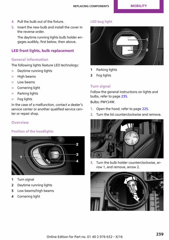
4. Pull the bulb out of the fixture.5. Insert the new bulb and install the cover in
the reverse order.The daytime running lights bulb holder en‐gages audibly, first below, then above.
LED front lights, bulb replacement
General informationThe following lights feature LED technology:▷ Daytime running lights▷ High beams▷ Low beams▷ Cornering light▷ Parking lights▷ Fog lightsIn the case of a malfunction, contact a dealer’sservice center or another qualified service cen‐ter or repair shop.
Overview
Position of the headlights
1 Turn signal2 Daytime running lights3 Low beams/high beams4 Cornering light
LED bug light
1 Parking lights2 Fog lights
Turn signalFollow the general instructions on lights andbulbs, refer to page 235.Bulbs: PWY24W.
1. Open the hood, refer to page 225.2. Turn the lid counterclockwise and remove.
3. Turn the bulb holder counterclockwise, ar‐row 1, and remove, arrow 2.
Seite 239
Replacing components MOBILITY
239Online Edition for Part no. 01 40 2 976 632 - X/16
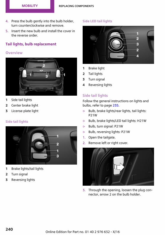
4. Press the bulb gently into the bulb holder,turn counterclockwise and remove.
5. Insert the new bulb and install the cover inthe reverse order.
Tail lights, bulb replacement
Overview
1 Side tail lights2 Center brake light3 License plate light
Side tail lights
1 Brake lights/tail lights2 Turn signal3 Reversing lights
Side LED tail lights
1 Brake light2 Tail lights3 Turn signal4 Reversing lights
Side tail lightsFollow the general instructions on lights andbulbs, refer to page 235.▷ Bulb, brake lights/rear lights, tail lights:
P21W▷ Bulb, brake lights/LED tail lights: H21W▷ Bulb, turn signal: P21W▷ Bulb, reversing lights: P21W1. Open the tailgate.2. Remove left or right cover.
3. Through the opening, loosen the plug con‐nector, arrow 2 on the bulb holder.
Seite 240
MOBILITY Replacing components
240 Online Edition for Part no. 01 40 2 976 632 - X/16

Press the latches together, arrows 1, andremove the bulb holder.
4. Remove the bulb holder from the opening.5. Press the nonworking bulb gently into the
socket, turn counterclockwise and remove.▷ Arrow 1: brake lights/tail lights.▷ Arrow 2: turn signal.▷ Arrow 3: reversing light.
6. Proceed in the reverse order to insert thenew bulb and attach the bulb holder. Makesure that the bulb holder engages in all fas‐teners.
Central brake lamp and license platelampFollow the general instructions on lights andbulbs, refer to page 235.The lights feature LED technology. In the caseof a malfunction, contact a dealer’s service cen‐ter or another qualified service center or repairshop.
Side turn signal, bulb replacementFollow the general instructions on lights andbulbs, refer to page 235.
Bulb: WY5W
1. Push the side turn signal forward in thedriving direction, arrow 1, and swing it out‐ward, arrow 2.
2. ▷ On the left facing the driving direction:turn the bulb holder clockwise and re‐move.
▷ On the right facing the driving direc‐tion: turn the bulb holder counterclock‐wise and remove.
3. Replace the bulb.4. Insert the bulb holder.5. Insert the rear side turn signal, arrow 1, and
swing it forward, arrow 2.
Vehicle batteryMaintenanceThe battery is maintenance-free.The added amount of acid is sufficient for theservice life of the battery.
Seite 241
Replacing components MOBILITY
241Online Edition for Part no. 01 40 2 976 632 - X/16
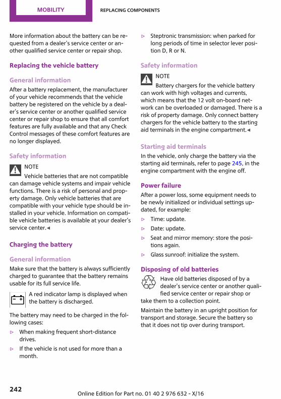
More information about the battery can be re‐quested from a dealer’s service center or an‐other qualified service center or repair shop.
Replacing the vehicle battery
General informationAfter a battery replacement, the manufacturerof your vehicle recommends that the vehiclebattery be registered on the vehicle by a deal‐er’s service center or another qualified servicecenter or repair shop to ensure that all comfortfeatures are fully available and that any CheckControl messages of these comfort features areno longer displayed.
Safety informationNOTEVehicle batteries that are not compatible
can damage vehicle systems and impair vehiclefunctions. There is a risk of personal and prop‐erty damage. Only vehicle batteries that arecompatible with your vehicle type should be in‐stalled in your vehicle. Information on compati‐ble vehicle batteries is available at your dealer’sservice center.◀
Charging the battery
General informationMake sure that the battery is always sufficientlycharged to guarantee that the battery remainsusable for its full service life.
A red indicator lamp is displayed whenthe battery is discharged.
The battery may need to be charged in the fol‐lowing cases:▷ When making frequent short-distance
drives.▷ If the vehicle is not used for more than a
month.
▷ Steptronic transmission: when parked forlong periods of time in selector lever posi‐tion D, R or N.
Safety informationNOTEBattery chargers for the vehicle battery
can work with high voltages and currents,which means that the 12 volt on-board net‐work can be overloaded or damaged. There is arisk of property damage. Only connect batterychargers for the vehicle battery to the startingaid terminals in the engine compartment.◀
Starting aid terminalsIn the vehicle, only charge the battery via thestarting aid terminals, refer to page 245, in theengine compartment with the engine off.
Power failureAfter a power loss, some equipment needs tobe newly initialized or individual settings up‐dated, for example:▷ Time: update.▷ Date: update.▷ Seat and mirror memory: store the posi‐
tions again.▷ Glass sunroof: initialize the system.
Disposing of old batteriesHave old batteries disposed of by adealer’s service center or another quali‐fied service center or repair shop or
take them to a collection point.Maintain the battery in an upright position fortransport and storage. Secure the battery sothat it does not tip over during transport.
Seite 242
MOBILITY Replacing components
242 Online Edition for Part no. 01 40 2 976 632 - X/16
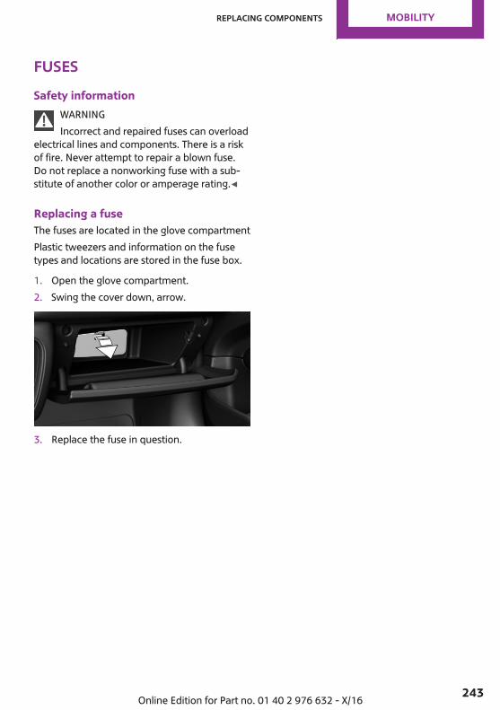
FusesSafety information
WARNINGIncorrect and repaired fuses can overload
electrical lines and components. There is a riskof fire. Never attempt to repair a blown fuse.Do not replace a nonworking fuse with a sub‐stitute of another color or amperage rating.◀
Replacing a fuseThe fuses are located in the glove compartmentPlastic tweezers and information on the fusetypes and locations are stored in the fuse box.
1. Open the glove compartment.2. Swing the cover down, arrow.
3. Replace the fuse in question.
Seite 243
Replacing components MOBILITY
243Online Edition for Part no. 01 40 2 976 632 - X/16
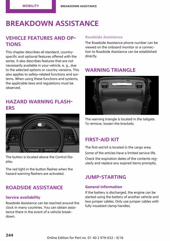
Breakdown assistanceVehicle features and op‐tionsThis chapter describes all standard, country-specific and optional features offered with theseries. It also describes features that are notnecessarily available in your vehicle, e. g., dueto the selected options or country versions. Thisalso applies to safety-related functions and sys‐tems. When using these functions and systems,the applicable laws and regulations must beobserved.
Hazard warning flash‐ers
The button is located above the Control Dis‐play.
The red light in the button flashes when thehazard warning flashers are activated.
Roadside AssistanceService availabilityRoadside Assistance can be reached around theclock in many countries. You can obtain assis‐tance there in the event of a vehicle break‐down.
Roadside AssistanceThe Roadside Assistance phone number can beviewed on the onboard monitor or a connec‐tion to Roadside Assistance can be establisheddirectly.
Warning triangle
The warning triangle is located in the tailgate.To remove, loosen the brackets.
First-aid kitThe first-aid kit is located in the cargo area.Some of the articles have a limited service life.Check the expiration dates of the contents reg‐ularly and replace any expired items promptly.
Jump-startingGeneral informationIf the battery is discharged, the engine can bestarted using the battery of another vehicle andtwo jumper cables. Only use jumper cables withfully insulated clamp handles.
Seite 244
MOBILITY Breakdown assistance
244 Online Edition for Part no. 01 40 2 976 632 - X/16
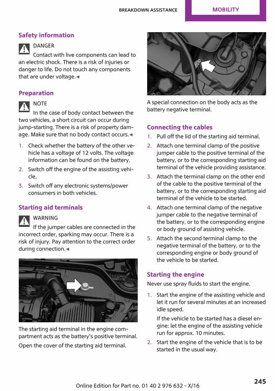
Safety informationDANGERContact with live components can lead to
an electric shock. There is a risk of injuries ordanger to life. Do not touch any componentsthat are under voltage.◀
PreparationNOTEIn the case of body contact between the
two vehicles, a short circuit can occur duringjump-starting. There is a risk of property dam‐age. Make sure that no body contact occurs.◀
1. Check whether the battery of the other ve‐hicle has a voltage of 12 volts. The voltageinformation can be found on the battery.
2. Switch off the engine of the assisting vehi‐cle.
3. Switch off any electronic systems/powerconsumers in both vehicles.
Starting aid terminalsWARNINGIf the jumper cables are connected in the
incorrect order, sparking may occur. There is arisk of injury. Pay attention to the correct orderduring connection.◀
The starting aid terminal in the engine com‐partment acts as the battery's positive terminal.Open the cover of the starting aid terminal.
A special connection on the body acts as thebattery negative terminal.
Connecting the cables1. Pull off the lid of the starting aid terminal.2. Attach one terminal clamp of the positive
jumper cable to the positive terminal of thebattery, or to the corresponding starting aidterminal of the vehicle providing assistance.
3. Attach the terminal clamp on the other endof the cable to the positive terminal of thebattery, or to the corresponding starting aidterminal of the vehicle to be started.
4. Attach one terminal clamp of the negativejumper cable to the negative terminal ofthe battery, or to the corresponding engineor body ground of assisting vehicle.
5. Attach the second terminal clamp to thenegative terminal of the battery, or to thecorresponding engine or body ground ofthe vehicle to be started.
Starting the engineNever use spray fluids to start the engine.
1. Start the engine of the assisting vehicle andlet it run for several minutes at an increasedidle speed.If the vehicle to be started has a diesel en‐gine: let the engine of the assisting vehiclerun for approx. 10 minutes.
2. Start the engine of the vehicle that is to bestarted in the usual way.
Seite 245
Breakdown assistance MOBILITY
245Online Edition for Part no. 01 40 2 976 632 - X/16
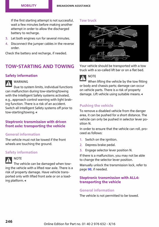
If the first starting attempt is not successful,wait a few minutes before making anotherattempt in order to allow the dischargedbattery to recharge.
3. Let both engines run for several minutes.4. Disconnect the jumper cables in the reverse
order.Check the battery and recharge, if needed.
Tow-starting and towingSafety information
WARNINGDue to system limits, individual functions
can malfunction during tow-starting/towingwith the Intelligent Safety systems activated,e.g., approach control warning with light brak‐ing function. There is a risk of an accident.Switch all Intelligent Safety systems off prior totow-starting/towing.◀
Steptronic transmission with drivenfront axle: transporting the vehicle
General informationThe vehicle must not be towed if the frontwheels are touching the ground.
Safety informationNOTEThe vehicle can be damaged when tow‐
ing the vehicle with a lifted rear axle. There is arisk of property damage. Have vehicle trans‐ported only with lifted front axle or on a load‐ing platform.◀
Tow truck
Your vehicle should be transported with a towtruck with a so-called lift bar or on a flat bed.
NOTEWhen lifting the vehicle by the tow fitting
or body and chassis parts; damage can occuron vehicle parts. There is a risk of propertydamage. Lift vehicle using suitable means.◀
Pushing the vehicleTo remove a disabled vehicle from the dangerarea, it can be pushed for a short distance. Thevehicle can only be pushed in selector lever po‐sition N.In order to ensure that the vehicle can roll, pro‐ceed as follows:
1. Switch on the ignition.2. Depress brake pedal.3. Engage selector lever position N.If there is a malfunction, you may not be ableto change the selector lever position.Manually unlock the transmission lock, refer topage 98, if needed.
Steptronic transmission with ALL4:transporting the vehicle
General informationThe vehicle is not permitted to be towed.
Seite 246
MOBILITY Breakdown assistance
246 Online Edition for Part no. 01 40 2 976 632 - X/16
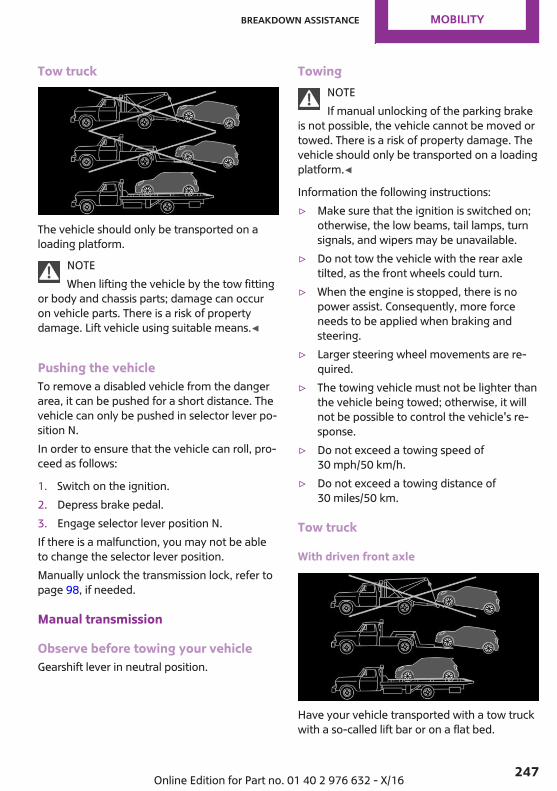
Tow truck
The vehicle should only be transported on aloading platform.
NOTEWhen lifting the vehicle by the tow fitting
or body and chassis parts; damage can occuron vehicle parts. There is a risk of propertydamage. Lift vehicle using suitable means.◀
Pushing the vehicleTo remove a disabled vehicle from the dangerarea, it can be pushed for a short distance. Thevehicle can only be pushed in selector lever po‐sition N.In order to ensure that the vehicle can roll, pro‐ceed as follows:
1. Switch on the ignition.2. Depress brake pedal.3. Engage selector lever position N.If there is a malfunction, you may not be ableto change the selector lever position.Manually unlock the transmission lock, refer topage 98, if needed.
Manual transmission
Observe before towing your vehicleGearshift lever in neutral position.
TowingNOTEIf manual unlocking of the parking brake
is not possible, the vehicle cannot be moved ortowed. There is a risk of property damage. Thevehicle should only be transported on a loadingplatform.◀
Information the following instructions:▷ Make sure that the ignition is switched on;
otherwise, the low beams, tail lamps, turnsignals, and wipers may be unavailable.
▷ Do not tow the vehicle with the rear axletilted, as the front wheels could turn.
▷ When the engine is stopped, there is nopower assist. Consequently, more forceneeds to be applied when braking andsteering.
▷ Larger steering wheel movements are re‐quired.
▷ The towing vehicle must not be lighter thanthe vehicle being towed; otherwise, it willnot be possible to control the vehicle's re‐sponse.
▷ Do not exceed a towing speed of30 mph/50 km/h.
▷ Do not exceed a towing distance of30 miles/50 km.
Tow truck
With driven front axle
Have your vehicle transported with a tow truckwith a so-called lift bar or on a flat bed.
Seite 247
Breakdown assistance MOBILITY
247Online Edition for Part no. 01 40 2 976 632 - X/16
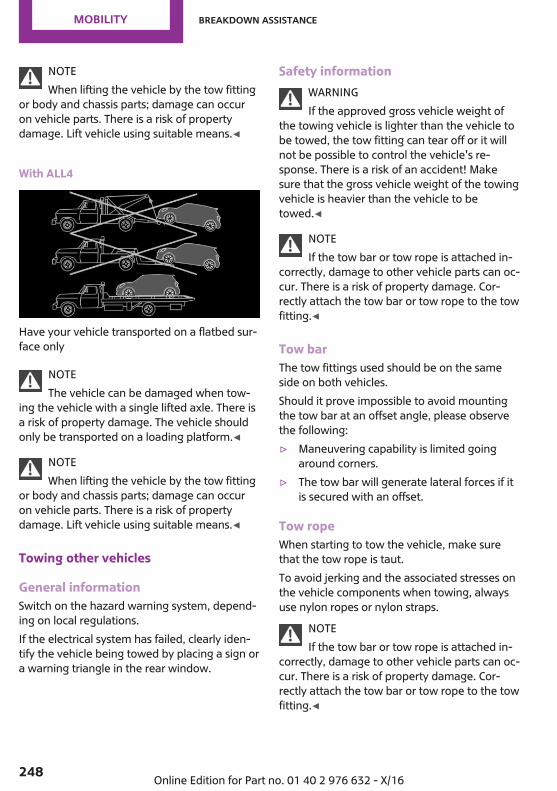
NOTEWhen lifting the vehicle by the tow fitting
or body and chassis parts; damage can occuron vehicle parts. There is a risk of propertydamage. Lift vehicle using suitable means.◀
With ALL4
Have your vehicle transported on a flatbed sur‐face only
NOTEThe vehicle can be damaged when tow‐
ing the vehicle with a single lifted axle. There isa risk of property damage. The vehicle shouldonly be transported on a loading platform.◀
NOTEWhen lifting the vehicle by the tow fitting
or body and chassis parts; damage can occuron vehicle parts. There is a risk of propertydamage. Lift vehicle using suitable means.◀
Towing other vehicles
General informationSwitch on the hazard warning system, depend‐ing on local regulations.If the electrical system has failed, clearly iden‐tify the vehicle being towed by placing a sign ora warning triangle in the rear window.
Safety informationWARNINGIf the approved gross vehicle weight of
the towing vehicle is lighter than the vehicle tobe towed, the tow fitting can tear off or it willnot be possible to control the vehicle's re‐sponse. There is a risk of an accident! Makesure that the gross vehicle weight of the towingvehicle is heavier than the vehicle to betowed.◀
NOTEIf the tow bar or tow rope is attached in‐
correctly, damage to other vehicle parts can oc‐cur. There is a risk of property damage. Cor‐rectly attach the tow bar or tow rope to the towfitting.◀
Tow barThe tow fittings used should be on the sameside on both vehicles.Should it prove impossible to avoid mountingthe tow bar at an offset angle, please observethe following:▷ Maneuvering capability is limited going
around corners.▷ The tow bar will generate lateral forces if it
is secured with an offset.
Tow ropeWhen starting to tow the vehicle, make surethat the tow rope is taut.To avoid jerking and the associated stresses onthe vehicle components when towing, alwaysuse nylon ropes or nylon straps.
NOTEIf the tow bar or tow rope is attached in‐
correctly, damage to other vehicle parts can oc‐cur. There is a risk of property damage. Cor‐rectly attach the tow bar or tow rope to the towfitting.◀
Seite 248
MOBILITY Breakdown assistance
248 Online Edition for Part no. 01 40 2 976 632 - X/16

Tow fitting
General information
The screw-in tow fitting should always be car‐ried in the vehicle.The tow fitting can be screwed in at the front orrear of the vehicle.The tow fitting and the onboard vehicle tool kit,refer to page 234, are together in the cargoarea.Use of the tow fitting:▷ Use only the tow fitting provided with the
vehicle and screw it all the way in.▷ Use the tow fitting for towing on paved
roads only.▷ Avoid lateral loading of the tow fitting, for
instance do not lift the vehicle by the towfitting.
Safety informationNOTEIf the tow fitting is not used as intended,
there can be damage to the vehicle or to thetow fitting. There is a risk of property damage.Observe the notes on using the tow fitting.◀
Screw thread for tow fitting
Threaded holes for the tow fitting are located inthe front and rear of the vehicle on the rightside with respect to the direction of travel.Press on the mark on the edge of the cover topush it out.
Tow-starting
Steptronic transmissionDo not tow-start the vehicle.Tow-starting the engine is not possible due tothe Steptronic transmission.Have the reasons for the starting difficultiescorrected by a dealer’s service center or an‐other qualified service center or repair shop.
Manual transmissionIf possible, do not tow-start the vehicle butstart the engine by jump-starting, refer topage 244. If the vehicle is equipped with a cat‐alytic converter, only tow-start while the engineis cold.
1. Switch on the hazard warning system andcomply with local regulations.
2. Switch on the ignition, refer to page 81.3. Engage third gear.4. Have the vehicle tow-started with the
clutch pedal pressed and slowly release thepedal. After the engine starts, immediatelypress on the clutch pedal again.
Seite 249
Breakdown assistance MOBILITY
249Online Edition for Part no. 01 40 2 976 632 - X/16
5. Stop at a suitable location, remove the towbar or rope, and switch off the hazardwarning system.
6. Have the vehicle checked by a dealer’sservice center or another qualified servicecenter or repair shop.
Seite 250
MOBILITY Breakdown assistance
250 Online Edition for Part no. 01 40 2 976 632 - X/16
CareVehicle features and op‐tionsThis chapter describes all standard, country-specific and optional features offered with theseries. It also describes features that are notnecessarily available in your vehicle, e. g., dueto the selected options or country versions. Thisalso applies to safety-related functions and sys‐tems. When using these functions and systems,the applicable laws and regulations must beobserved.
Vehicle washesGeneral informationRegularly remove foreign objects such as leavesin the area below the windshield when thehood is raised.Wash your vehicle frequently, particularly inwinter. Intense soiling and road salt can dam‐age the vehicle.
Steam jets or high-pressure washers
Safety informationNOTEWhen cleaning with high-pressure wash‐
ers, components can be damaged due to thepressure or temperatures being too high. Thereis a risk of property damage. Maintain sufficientdistance and do not spray too long continu‐ously. Follow the operating instructions for thehigh-pressure washer.◀
Distances and temperature▷ Maximum temperature: 140 ℉/60 ℃.▷ Minimum distance from sensors, cameras,
seals: 12 inches/30 cm.
▷ Minimum distance from glass sunroof:31.5 inches/80 cm.
Automatic vehicle washes
Safety informationNOTEImproper use of automatic vehicle
washes can cause damage to the vehicle. Thereis a risk of damage to property. Follow the fol‐lowing instructions:▷ Give preference to cloth vehicle washes or
those that use soft brushes in order toavoid paint damage.
▷ Avoid vehicle washes with guide railshigher than 4 in/10 cm to avoid damage tothe chassis.
▷ Observe the tire width of the guide rail toavoid damage to tires and rims.
▷ Fold in exterior mirrors to avoid damage tothe exterior mirrors.
▷ With rod antenna: unscrew the rod antennato avoid rod antenna breakage.
▷ Deactivate the wiper and, if necessary, rainsensor to avoid damage to the wiper sys‐tem.◀
Before driving into a vehicle washIn order to ensure that the vehicle can roll in avehicle wash, take the following steps:Manual transmission:
1. Drive into the vehicle wash.2. Shift to neutral.3. Switch the engine off.Steptronic transmission:
1. Drive into the vehicle wash.2. Engage selector lever position N.
Seite 251
Care MOBILITY
251Online Edition for Part no. 01 40 2 976 632 - X/16
3. Make sure that the parking brake is re‐leased.
4. Switch the engine off.In this way, the ignition remains switchedon, and two Check-Control messages aredisplayed.
Some vehicle washes do not permit persons inthe vehicle. The vehicle cannot be locked fromthe outside when in selector lever position N. Asignal is sounded when an attempt is made tolock the vehicle.
Driving out of a vehicle washTo start the engine with manual transmission:
1. Ensure that the vehicle key is in the car.2. Press on the clutch pedal.3. Press the Start/Stop button.To start the engine with Steptronic transmis‐sion:
1. Ensure that the vehicle key is in the car.2. Depress the brake pedal.3. Press the Start/Stop button.
HeadlightsDo not rub the headlights dry and do not useabrasive or acidic cleaning agents.Soak areas that have been dirtied, for instancefrom insects, with shampoo and wash off withwater.Thaw ice with de-icing spray; do not use an icescraper.
After washing the vehicleAfter washing the vehicle, apply the brakesbriefly to dry them; otherwise, braking actioncan be reduced. The heat generated whenbraking helps to dry the brake discs and padsand protect them from corrosion.Completely remove all residues on the win‐dows, to minimize loss of visibility due to
smearing and to reduce wiper noises and wiperblade wear.
Vehicle careVehicle care products
General informationMINI recommends using vehicle care andcleaning products from MINI. Suitable careproducts are available from a dealer’s servicecenter or another qualified service center or re‐pair shop.
Safety informationWARNINGCleansers can contain substances that are
dangerous and harmful to your health. There isa risk of injury. When cleaning the interior,open the doors or windows. Only use productsintended for cleaning vehicles. Follow the in‐structions on the container.◀
Vehicle paintRegular care contributes to driving safety andvalue retention. Environmental influences inareas with elevated air pollution or natural con‐taminants, such as tree resin or pollen can af‐fect the vehicle's paintwork. Tailor the fre‐quency and extent of your vehicle care to theseinfluences.Aggressive substances such as spilled fuel, oil,grease or bird droppings, must be removed im‐mediately to prevent the finish from being al‐tered or discolored.
Leather careRemove dust from the leather regularly, using acloth or vacuum cleaner.Otherwise, particles of dust and road grimechafe in pores and folds, and lead to increased
Seite 252
MOBILITY Care
252 Online Edition for Part no. 01 40 2 976 632 - X/16

wear and premature degradation of the leathersurface.To guard against discoloration, such as fromclothing, clean leather and provide leather careroughly every two months.Clean light-colored leather more frequently be‐cause soiling on such surfaces is substantiallymore visible.Use leather care products; otherwise, dirt andgrease will gradually break down the protectivelayer of the leather surface.
Upholstery material care
General informationVacuum the upholstery regularly with a vac‐uum cleaner.If upholstery is very dirty, for instance with bev‐erage stains, use a soft sponge or microfibercloth with a suitable interior cleaner.Clean the upholstery down to the seams usinglarge sweeping motions. Avoid rubbing the ma‐terial vigorously.
Safety informationNOTEOpen Velcro® fasteners on articles of
clothing can damage the seat covers. There is arisk of property damage. Ensure that any Vel‐cro® fasteners are closed.◀
Caring for special components
Light-alloy wheelsWhen cleaning the vehicle, use only neutralwheel cleaners having a pH value from 5 to 9.Do not use abrasive cleaning agents or steamjets above 140 ℉/60 ℃. Follow the manufac‐turer's instructions.Aggressive, acidic or alkaline cleaning agentscan destroy the protective layer of adjacentcomponents, such as the brake disk.
After cleaning, apply the brakes briefly to drythem. The heat generated during braking driesbrake discs and brake pads and protects themagainst corrosion.
Chrome surfacesCarefully clean components such as the radia‐tor grille or door handles with an ample supplyof water, possibly with shampoo added, partic‐ularly when they have been exposed to roadsalt.
Rubber componentsEnvironmental influences can cause surfacesoiling of rubber parts and a loss of gloss. Useonly water and suitable cleaning agents forcleaning.Treat especially worn rubber parts with rubbercare agents at regular intervals. When cleaningrubber seals, do not use any silicon-containingvehicle care products in order to avoid damageor noises.
Fine wood partsClean fine wood facing and fine wood compo‐nents only with a moist rag. Then dry with asoft cloth.
Plastic componentsNOTECleansers that contain alcohol or solvents,
such as lacquer thinners, heavy-duty grease re‐movers, fuel, or such, can damage plastic parts.There is a risk of property damage. Clean with amicrofiber cloth. Dampen cloth lightly with wa‐ter.◀
Plastic components are e. g:▷ Imitation leather surfaces.▷ Roofliner.▷ Lamp lenses.▷ Instrument cluster cover.▷ Matt black spray-coated components.
Seite 253
Care MOBILITY
253Online Edition for Part no. 01 40 2 976 632 - X/16
▷ Painted parts in the interior.Clean with a microfiber cloth.Dampen cloth lightly with water.Do not soak the roofliner.
Safety beltsWARNINGChemical cleansers can destroy the safety
belt webbing. Missing protective effect of thesafety belts. There is a risk of injuries or dangerto life. Use only a mild soapy solution for clean‐ing the safety belts.◀
Dirty belt straps impede the reeling action andthus have a negative impact on safety.Use only a mild soapy solution, with the safetybelts clipped into their buckles.Do not allow the switchs to retract the safetybelts until they are dry.
Carpets and floor matsWARNINGObjects in the driver's floor area can limit
the pedal distance or block a depressed pedal.There is a risk of an accident. Stow objects inthe vehicle such that they are secured and can‐not enter into the driver's floor area. Use floormats that are suitable for the vehicle and canbe safely attached to the floor. Do not useloose floor mats and do not layer several floormats. Make sure that there is sufficient clear‐ance for the pedals. Ensure that the floor matsare securely fastened again after they were re‐moved, e.g., for cleaning.◀
Floor mats can be removed from the vehicle'sinterior for cleaning.If the floor carpets are very dirty, clean with amicrofiber cloth and water or a textile cleaner.To prevent matting of the carpet, rub back andforth in the direction of travel only.
Sensor/camera lensesTo clean sensors and camera lenses, use a clothmoistened with a small amount of glass deter‐gent.
Displays/Screens/Projection lensesNOTEChemical cleansers, moisture or fluids of
any kind can damage the surface of displaysand screens. There is a risk of property dam‐age. Clean with a clean, antistatic microfibercloth.◀
NOTEThe surface of displays can be damaged
with improper cleaning. There is a risk of prop‐erty damage. Avoid pressure that is too highand do not use any scratching materials.◀
Clean with a clean, antistatic microfiber cloth.For stubborn soiling on the projection lens ofthe Head-up Display, dampen the microfibercloth with alcohol. Extending projection lens,refer to page 114.
Long-termWhen the vehicle is shut down for longer thanthree months, special measures must be taken.Further information is available from a dealer’sservice center or another qualified service cen‐ter or repair shop.
Seite 254
MOBILITY Care
254 Online Edition for Part no. 01 40 2 976 632 - X/16

Seite 255
Care MOBILITY
255Online Edition for Part no. 01 40 2 976 632 - X/16

FIND ME.
Online Edition for Part no. 01 40 2 976 632 - X/16

AT A GLANCE
CONTROLS
DRIVING TIPS
MOBILITY
REFERENCE
Online Edition for Part no. 01 40 2 976 632 - X/16
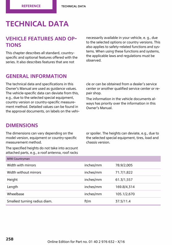
Technical dataVehicle features and op‐tionsThis chapter describes all standard, country-specific and optional features offered with theseries. It also describes features that are not
necessarily available in your vehicle, e. g., dueto the selected options or country versions. Thisalso applies to safety-related functions and sys‐tems. When using these functions and systems,the applicable laws and regulations must beobserved.
General informationThe technical data and specifications in thisOwner's Manual are used as guidance values.The vehicle-specific data can deviate from this,e.g., due to the selected special equipment,country version or country-specific measure‐ment method. Detailed values can be found inthe approval documents, on labels on the vehi‐
cle or can be obtained from a dealer’s servicecenter or another qualified service center or re‐pair shop.The information in the vehicle documents al‐ways has priority over the information in thisOwner's Manual.
DimensionsThe dimensions can vary depending on themodel version, equipment or country-specificmeasurement method.The specified heights do not take into accountattached parts, e.g., a roof antenna, roof racks
or spoiler. The heights can deviate, e.g., due tothe selected special equipment, tires, load andchassis version.
MINI Countryman
Width with mirrors inches/mm 78.9/2,005
Width without mirrors inches/mm 71.7/1,822
Height inches/mm 61.3/1,557
Length inches/mm 169.8/4,314
Wheelbase inches/mm 105.1/2,670
Smallest turning radius diam. ft/m 37.5/11.4
Seite 258
REFERENCE Technical data
258 Online Edition for Part no. 01 40 2 976 632 - X/16
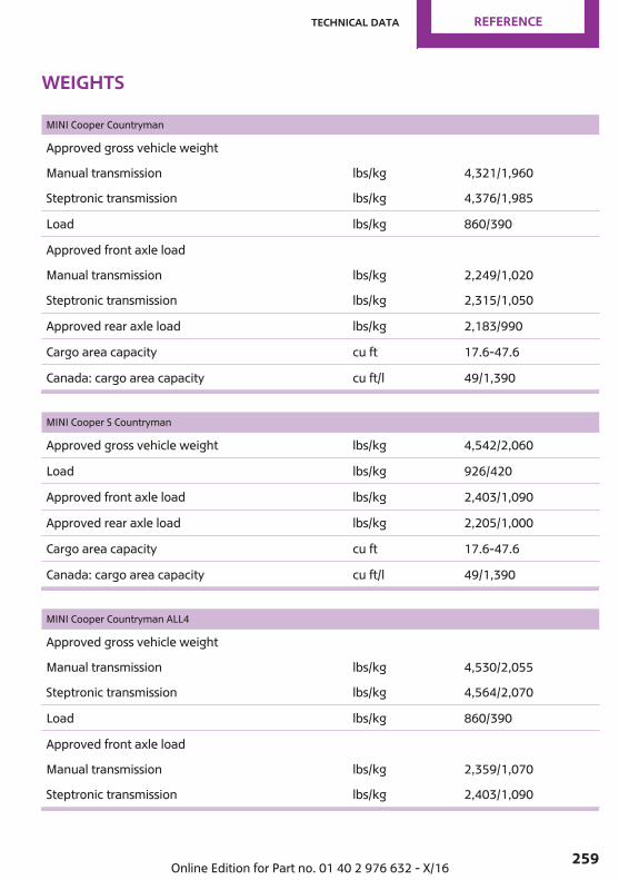
Weights
MINI Cooper Countryman
Approved gross vehicle weight
Manual transmission lbs/kg 4,321/1,960
Steptronic transmission lbs/kg 4,376/1,985
Load lbs/kg 860/390
Approved front axle load
Manual transmission lbs/kg 2,249/1,020
Steptronic transmission lbs/kg 2,315/1,050
Approved rear axle load lbs/kg 2,183/990
Cargo area capacity cu ft 17.6-47.6
Canada: cargo area capacity cu ft/l 49/1,390
MINI Cooper S Countryman
Approved gross vehicle weight lbs/kg 4,542/2,060
Load lbs/kg 926/420
Approved front axle load lbs/kg 2,403/1,090
Approved rear axle load lbs/kg 2,205/1,000
Cargo area capacity cu ft 17.6-47.6
Canada: cargo area capacity cu ft/l 49/1,390
MINI Cooper Countryman ALL4
Approved gross vehicle weight
Manual transmission lbs/kg 4,530/2,055
Steptronic transmission lbs/kg 4,564/2,070
Load lbs/kg 860/390
Approved front axle load
Manual transmission lbs/kg 2,359/1,070
Steptronic transmission lbs/kg 2,403/1,090
Seite 259
Technical data REFERENCE
259Online Edition for Part no. 01 40 2 976 632 - X/16
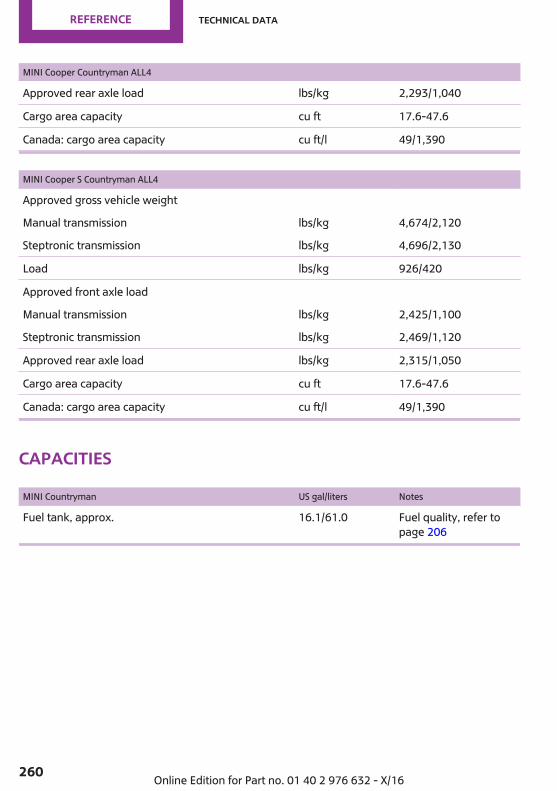
MINI Cooper Countryman ALL4
Approved rear axle load lbs/kg 2,293/1,040
Cargo area capacity cu ft 17.6-47.6
Canada: cargo area capacity cu ft/l 49/1,390
MINI Cooper S Countryman ALL4
Approved gross vehicle weight
Manual transmission lbs/kg 4,674/2,120
Steptronic transmission lbs/kg 4,696/2,130
Load lbs/kg 926/420
Approved front axle load
Manual transmission lbs/kg 2,425/1,100
Steptronic transmission lbs/kg 2,469/1,120
Approved rear axle load lbs/kg 2,315/1,050
Cargo area capacity cu ft 17.6-47.6
Canada: cargo area capacity cu ft/l 49/1,390
Capacities
MINI Countryman US gal/liters Notes
Fuel tank, approx. 16.1/61.0 Fuel quality, refer topage 206
Seite 260
REFERENCE Technical data
260 Online Edition for Part no. 01 40 2 976 632 - X/16
AppendixAny updates to the Owner's Manual of the ve‐hicle are listed here.
Updates made after theeditorial deadlineThese chapters of the printed Owner's Manualcontain updates made after the editorial dead‐line.▷ Overview: General settings: Data protec‐
tion.▷ Fuel quality: Petrol, refer to page 206.▷ Wheels and tires: Wheel change: Safety in‐
formation, refer to page 220, and Raisingvehicle, refer to page 221.
▷ Storage compartments: Center armrest, re‐fer to page 179.
▷ Replacing parts:Changing the wiper blades,refer to page 234.
▷ Installing child restraint systems:Installingchild restraint systems, refer to page 77.
License Texts and Certifi‐cationsThe following applies in addition to the radiotransmission license texts of the IntegratedOwner’s Manual in the vehicle.
Remote Control
Argentine RepublicCNC Aprobado No.: H-12091
Brazil
Este equipamento opera em caráter secun‐dário, isto é, não tem direito a proteção contrainterferência prejudicial, mesmo de estaçõesdo mesmo tipo, e não pode causar interferên‐cia a sistemas operando em caráter primário.
CanadaLe présent appareil est conforme aux CNR d'In‐dustrie Canada applicables aux appareils radioexempts de licence. L'exploitation est autoriséeaux deux conditions suivantes :(1) l'appareil ne doit pas produire de brouillage,et(2) tl'utilisateur de l'appareil doit accepter toutbrouillage radioélectrique subi, même si lebrouillage est susceptible d'en compromettre lefonctionnement.FCC § 15.19 Labelling requirementsThis device complies with Part 15 of the FCCRules and with Industry Canada licence-exemptRSS. Operation is subject to the following twoconditions:(1) This device may not cause harmful interfer‐ence, and(2) this device must accept any interference re‐ceived, including interference that may causeundesired operation.FCC § 15.21 Information to user
Seite 261
Appendix REFERENCE
261Online Edition for Part no. 01 40 2 976 632 - X/16
Changes or modifications not expressly ap‐proved by the party responsible for compliancecould void the user's authority to operate theequipment.
Indonesia29311/SDPPI/20132181
Japan
201-135124
MexicoCOFETEL: RLVBHEID13–0912Marca: HellaModelo (s): IDGNG1La operación de este equipo está sujeta a las si‐guientes dos condiciones:(1) es posible que este equipo o dispositivo nocause interferencia perjudicial y(2) este equipo o dispositivo debe aceptar cual‐quier interferencia, incluyendo la que puedacausar su operación no deseada.
OmanOMAN TRATRA/TA-R/1037/13D090258
Philippines
NTCType ApprovedNo.: ESD-1307076C
SingaporeComplies withIDA StandardsDA101586
South Africa
TA-2013/004APPROVED
Taiwan本產品符合低功率電波輻射性電機管理辦法 第十二條、第十四條等條文規定1. 經型式認證合格之低功率射頻電機,非經許可,公司、商號或使用者均不得擅自變更頻率、加大功率或變更原設計之特性及功能。2. 低功率射頻電機之使用不得影響飛航安全及干擾合法通信;經發現有干擾現象時,應立即停用,並改善至無干擾時方得繼續使用。
Seite 262
REFERENCE Appendix
262 Online Edition for Part no. 01 40 2 976 632 - X/16

前項合法通信,指依電信法規定作業之無線電通信。低功率射頻電機須忍受合法通信或工業、科學及醫療用電波輻射性電機設備之干擾。
UAETRA REGISTERED No: ER0107463/13DEALER No: DA0053436/10
USAFCC § 15.19 Labelling requirementsThis device complies with Part 15 of the FCCRules and with Industry Canada licence-exemptRSS. Operation is subject to the following twoconditions:(1) This device may not cause harmful interfer‐ence, and(2) this device must accept any interference re‐ceived, including interference that may causeundesired operation.FCC § 15.21 Information to userChanges or modifications not expressly ap‐proved by the party responsible for compliancecould void the user's authority to operate theequipment.
Wireless Charging
FCC ID: QZ9-WCA
FCC Part 18 complianceNOTE: This device complies with Part 18 of theFCC Rules. Changes or modifications not ex‐pressly approved by the party responsible for
compliance could void the user's authority tooperate the equipment. This product maycause interference to radio equipment andshould not be installed near maritime safetycommunications equipment or other criticalnavigation or communication equipment oper‐ating between 0.45–30 MHz.(a) The interference potential of device or sys‐tem: “Operation is subject to the following twoconditions:
1. This device may not cause harmful interfer‐ence, and
2. This device must accept any interferencereceived, including interference that maycause undesired operation.”
Wireless charging tray
Mounting position of the product.
NoteThis device has been tested for human expo‐sure limits and found compliant at a minimumdistance of 4 in/10 cm during operation.Therefore, a distance of 4 in/10 cm must bemaintained in every direction when operatingthe device.
Seite 263
Appendix REFERENCE
263Online Edition for Part no. 01 40 2 976 632 - X/16

Seite 264
REFERENCE
264 Online Edition for Part no. 01 40 2 976 632 - X/16

Seite 265
REFERENCE
265Online Edition for Part no. 01 40 2 976 632 - X/16

Seite 266
REFERENCE
266 Online Edition for Part no. 01 40 2 976 632 - X/16

Seite 267
REFERENCE
267Online Edition for Part no. 01 40 2 976 632 - X/16
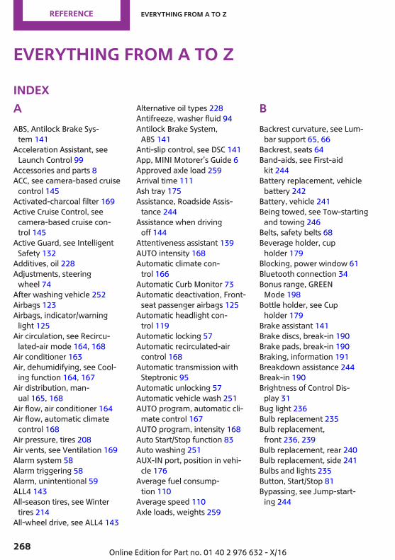
Everything from A to ZIndexAABS, Antilock Brake Sys‐
tem 141 Acceleration Assistant, see
Launch Control 99 Accessories and parts 8 ACC, see camera-based cruise
control 145 Activated-charcoal filter 169 Active Cruise Control, see
camera-based cruise con‐trol 145
Active Guard, see IntelligentSafety 132
Additives, oil 228 Adjustments, steering
wheel 74 After washing vehicle 252 Airbags 123 Airbags, indicator/warning
light 125 Air circulation, see Recircu‐
lated-air mode 164, 168 Air conditioner 163 Air, dehumidifying, see Cool‐
ing function 164, 167 Air distribution, man‐
ual 165, 168 Air flow, air conditioner 164 Air flow, automatic climate
control 168 Air pressure, tires 208 Air vents, see Ventilation 169 Alarm system 58 Alarm triggering 58 Alarm, unintentional 59 ALL4 143 All-season tires, see Winter
tires 214 All-wheel drive, see ALL4 143
Alternative oil types 228 Antifreeze, washer fluid 94 Antilock Brake System,
ABS 141 Anti-slip control, see DSC 141 App, MINI Motorer’s Guide 6 Approved axle load 259 Arrival time 111 Ash tray 175 Assistance, Roadside Assis‐
tance 244 Assistance when driving
off 144 Attentiveness assistant 139 AUTO intensity 168 Automatic climate con‐
trol 166 Automatic Curb Monitor 73 Automatic deactivation, Front-
seat passenger airbags 125 Automatic headlight con‐
trol 119 Automatic locking 57 Automatic recirculated-air
control 168 Automatic transmission with
Steptronic 95 Automatic unlocking 57 Automatic vehicle wash 251 AUTO program, automatic cli‐
mate control 167 AUTO program, intensity 168 Auto Start/Stop function 83 Auto washing 251 AUX-IN port, position in vehi‐
cle 176 Average fuel consump‐
tion 110 Average speed 110 Axle loads, weights 259
BBackrest curvature, see Lum‐
bar support 65, 66 Backrest, seats 64 Band-aids, see First-aid
kit 244 Battery replacement, vehicle
battery 242 Battery, vehicle 241 Being towed, see Tow-starting
and towing 246 Belts, safety belts 68 Beverage holder, cup
holder 179 Blocking, power window 61 Bluetooth connection 34 Bonus range, GREEN
Mode 198 Bottle holder, see Cup
holder 179 Brake assistant 141 Brake discs, break-in 190 Brake pads, break-in 190 Braking, information 191 Breakdown assistance 244 Break-in 190 Brightness of Control Dis‐
play 31 Bug light 236 Bulb replacement 235 Bulb replacement,
front 236, 239 Bulb replacement, rear 240 Bulb replacement, side 241 Bulbs and lights 235 Button, Start/Stop 81 Bypassing, see Jump-start‐
ing 244
Seite 268
REFERENCE Everything from A to Z
268 Online Edition for Part no. 01 40 2 976 632 - X/16
CCalifornia Proposition 65
Warning 8 Calling up mirror adjust‐
ment 58 Calling up seat adjustment 58 Camera-based assistance sys‐
tems, see IntelligentSafety 132
Camera-based cruise con‐trol 145
Camera lenses, care 254 Camera, rearview cam‐
era 157 Can holder, see Cup
holder 179 Car battery 241 Care, displays 254 Care, vehicle 252 Care, washing the vehicle 251 Cargo area 181 Cargo area, adapting size 185 Cargo area, enlarging 183 Cargo area lid 52 Cargo area, loading 182 Cargo area, seating sur‐
face 186 Cargo area, storage compart‐
ments 183 Cargo cover 182 Cargo position, rear seat back‐
rest 183 Cargo, stowing and secur‐
ing 182 Cargo straps 182 Carpet, care 254 Catalytic converter, see Hot
exhaust system 191 CBS Condition Based Serv‐
ice 232 Center armrest 179 Center console 16 Central instrument cluster,
LED ring 113
Central locking system, un‐locking, from inside 48
Central screen, see ControlDisplay 18
Changes, technical, see ForYour Own Safety 7
Changing parts 234 Changing wheels 220 Changing wheels/tires 213 Chassis number, see vehicle
identification number 10 Check Control 101 Checking the oil level elec‐
tronically 226 Children, seating position 76 Children, transporting
safely 76 Child restraint fixing system
LATCH 78 Child restraint system 76 Child restraint systems,
mounting 77 Child safety locks 80 Child seat, mounting 77 Child seats 76 Chrome parts, care 253 CID (central information dis‐
play), refer to On-Boardcomputer 109
Cigarette lighter 175 City light braking function
warning with Approach con‐trol 133
Cleaning, displays 254 Climate control 163, 166 Clothes hooks 180 Coasting 199 Coasting with engine decou‐
pled, coasting 199 Coasting with idling en‐
gine 199 Combination switch, see Turn
signals 87 Combi switch, see wiper sys‐
tem 88, 91 Comfort Access 49
Compartments in thedoors 179
Compass 173 Compressor 215 Condensation on win‐
dows 169 Condensation under the vehi‐
cle 192 Condition Based Service
CBS 232 Configuring driving pro‐
gram 144 Confirmation signal 57 Connecting device 33 Connecting mobile phone 33 Connecting smartphone 33 Connecting telephone 33 Connections 33 Control Display 18 Control Display, settings 30 Controller 19 Controller operation 19 Control systems, driving stabil‐
ity 141 Convenient opening 45 Coolant 230 Cooling function 164, 167 Cooling, maximum 167 Cooling system 230 Cornering light 120 Corrosion on brake discs 192 Cosmetic mirror 175 Country timer 116 Coupling, see Pairing 33 Courtesy lights during unlock‐
ing 45 Courtesy lights with the vehi‐
cle locked 45 Cruise control 151 Cruise control, active 145 Cruise control with distance
control, see camera-basedcruise control 145
Cruise control without dis‐tance control, see cruise con‐trol 151
Seite 269
Everything from A to Z REFERENCE
269Online Edition for Part no. 01 40 2 976 632 - X/16

Cruising range 106 Cup holder 179 Current fuel consumption 106
DDamage, tires 213 Damping control, dy‐
namic 143 Data protection, settings 32 Data, technical 258, 260 Date 31 Date display 106 Daytime running lights 120 Defrosting, see defrosting the
windows 165 Defrosting, see Windows, de‐
frosting 169 Defrosting the windows 165 Dehumidifying, air 164, 167 Deleting personal data 33 Deletion of personal data 33 Destination distance 111 Device list 33 Digital clock 105 Digital compass 173 Dimensions 258 Dimmable exterior mirrors 73 Dimmable interior mirror 74 Direction indicator, see Turn
signals 87 Display, electronic, instrument
cluster 101 Display, engine tempera‐
ture 111 Display, GREEN Mode 196 Display lighting, see Instru‐
ment lighting 121 Displays 100 Displays, care 254 Disposal, coolant 231 Disposal, vehicle battery 242 Distance control, see PDC 153 Distance to destination 111 Divided screen view, split
screen 24
Drive-off assistant 144 Drive-off assistant, see
DSC 141 Driver assistance, see Intelli‐
gent Safety 132 Driver profiles 54 Driver profiles, exporting pro‐
files 56 Driver profiles, importing pro‐
files 56 Driving Dynamics Control, see
MINI Driving Modesswitch 143
Driving Excitement,SPORT 112
Driving instructions, break-in 190
Driving mode, GREEN 196 Driving mode, GREEN driving
style analysis 200 Driving modes 143 Driving notes, general 191 Driving on poor roads 193 Driving on racetracks 194 Driving stability control sys‐
tems 141 Driving style analysis 200 Driving tip, GREEN tip 198 Driving tips 191 DSC Dynamic Stability Con‐
trol 141 DTC Dynamic Traction Con‐
trol 142 Dynamic Damping Con‐
trol 143 Dynamic Stability Control
DSC 141 Dynamic Traction Control
DTC 142
EEasy Opener 50 Electronic displays, instrument
cluster 101
Electronic oil measure‐ment 226
Electronic Stability ProgramESP, see DSC 141
Emergency release, fuel fillerflap 205
Emergency service, see Road‐side Assistance 244
Emergency wheel, compactwheel, see Emergencywheel 223
Energy Control 106 Engine, automatic Start/Stop
function 83 Engine, automatic switch-
off 83 Engine compartment 224 Engine compartment, working
in 224 Engine coolant 230 Engine idling when driving,
coasting 199 Engine oil 226 Engine oil, adding 227 Engine oil additives 228 Engine oil change 228 Engine oil filler neck 227 Engine oil types, alterna‐
tive 228 Engine oil types, suitable 228 Engine start, jump-start‐
ing 244 Engine start, see Starting the
engine 82 Engine stop 83 Engine temperature, dis‐
play 111 Entering a vehicle wash 251 Equipment, interior 171 Error displays, see Check Con‐
trol 101 ESP Electronic Stability Pro‐
gram, see DSC 141 Exchanging wheels/tires 213 Exhaust system 191 Exiting a vehicle wash 251
Seite 270
REFERENCE Everything from A to Z
270 Online Edition for Part no. 01 40 2 976 632 - X/16

Exterior mirror, automaticdimming feature 73
Exterior mirrors 72 Exterior mirrors, Automatic
Curb Monitor 73 External start 244 External temperature dis‐
play 105 External temperature warn‐
ing 105 Eyes for securing cargo 182
FFailure message, see Check
Control 101 False alarm, see Unintentional
alarm 59 Fan, see Air flow 164, 168 Favorites buttons, onboard
monitor 25 Filler neck for engine oil 227 Fine wood, care 253 First-aid kit 244 Fish, MINIMALISM display 200 Flat tire, changing wheels 220 Flat Tire Monitor FTM 130 Flat tire, repairing 215 Flat tire, Tire Pressure Monitor
TPM 126 Flat tire, warning
lamp 128, 131 Flooding 191 Floor carpet, care 254 Floor mats, care 254 Fogged up windows 165 Fold-away position, wind‐
shield wipers 90, 93 Fold back rear seat backr‐
ests 183 Foot brake 191 For Your Own Safety 7 Front airbags 123 Front fog lights 121 Front-seat passenger airbags,
automatic deactivation 125
Front-seat passenger airbags,indicator light 126
Front seats 64 FTM Flat Tire Monitor 130 Fuel 206 Fuel cap 204 Fuel consumption, see Aver‐
age fuel consumption 110 Fuel filler flap 204 Fuel gauge 105 Fuel quality 206 Fuel recommendation 206 Fuel, tank capacity 260 Fuse 243
GGarage door opener, see Uni‐
versal Integrated RemoteControl 171
Gasoline 206 Gear change, Steptronic trans‐
mission 96 Gear shift indicator 107 General driving notes 191 General settings 30 Glare shield 175 Glass sunroof, initialize the
system 63 Glass sunroof, see Panoramic
glass sunroof 62 Glove compartment 178 GREEN bonus range 198 GREEN Mode 196 GREEN - program, driving dy‐
namics 143 GREEN tip, driving tip 198 Gross vehicle weight, ap‐
proved 259 Ground clearance 192
HHalogen headlights 236 Handbrake, see Parking
brake 85
Hand-held transmitter, alter‐nating code 172
Hazard warning flashers 244 Head airbag 123 Headlight control, auto‐
matic 119 Headlight courtesy delay fea‐
ture 119 Headlight flasher 88 Headlight glass 235 Headlights, care 252 Head restraints, front 69 Head restraints, rear 71 Head-up Display 114 Head-up Display, standard
view 114 Heavy cargo, stowing
cargo 182 High-beam Assistant 120 High beams 88 High beams/low beams, see
High-beam Assistant 120 Hills 192 Hill start assistant, see Drive-
off assistant 144 Holder for beverages 179 Homepage 6 Hood 224 Horn 14 Hot exhaust system 191 HUD Head-up Display 114 Hydroplaning 191
IIce warning, see External tem‐
perature warning 105 Icy roads, see External tem‐
perature warning 105 Identification marks, tires 211 Identification number, see ve‐
hicle identification num‐ber 10
Ignition off 81 Ignition on 81
Seite 271
Everything from A to Z REFERENCE
271Online Edition for Part no. 01 40 2 976 632 - X/16
Illuminated ring, central in‐strument cluster 113
Indication of a flattire 128, 131
Indicator light, see Check Con‐trol 101
Individual air distribu‐tion 165, 168
Individual settings, see driverprofiles 54
Inflation pressure, tires 208 Inflation pressure warning,
tires 130 Information 6 Initialize, Tire Pressure Moni‐
tor TPM 127 Initializing, Flat Tire Monitor
FTM 131 Instrument cluster 100 Instrument cluster, electronic
displays 101 Instrument lighting 121 Integrated key 47 Integrated Owner's Manual in
the vehicle 40 Intelligent Safety 132 Intended use 7 Intensity, AUTO program 168 Interior equipment 171 Interior lights 122 Interior lights during unlock‐
ing 45 Interior lights with the vehicle
locked 45 Interior mirror, automatic
dimming feature 74 Interior mirror, compass 173 Interior mirror, manually dim‐
mable 74 Interior motion sensor 59 Internet site 6 Interval display, service re‐
quirements 106 Interval mode 89, 92 In the vicinity of the center
console 16
In the vicinity of the roof‐liner 17
In the vicinity of the steeringwheel 14
JJacking points for the vehicle
jack 221 Joystick, Steptronic transmis‐
sion 96 Jump-starting 244
KKeyless Go, see Comfort Ac‐
cess 49 Key, see Integrated key 47 Key, see Remote control 44 Kickdown, Steptronic trans‐
mission 96 Knee airbag 124
LLabel on recommended
tires 214 Language, on the Control Dis‐
play 30 Lashing eyes 182 LATCH child restraint fixing
system 78 Launch Control 99 Leather, care 252 LED ring, central instrument
cluster 113 LEDs, light-emitting di‐
odes 235 Letters and numbers, enter‐
ing 21 Light 118 Light-alloy wheels, care 253 Light-emitting diodes,
LEDs 235 Lighter 175 Lighting 118
Light replacement 235 Light replacement,
front 236, 239 Light replacement, rear 240 Light replacement, side 241 Lights and bulbs 235 Light switch 118 List of all messages 32 Load 182 Loading 181 Loading position 183 Locking, automatic 57 Locking, from inside 48 Locking, settings 57 Low beams 118 Low beams, automatic, see
High-beam Assistant 120 Lower back support 66 Lower back support, mechani‐
cal 65 Luggage rack, see Roof-
mounted luggage rack 193 Lumbar support 66 Lumbar support, mechani‐
cal 65
MMaintenance 232 Maintenance require‐
ments 232 Maintenance, service require‐
ments 106 Maintenance system,
MINI 232 Make-up mirror 175 Malfunction displays, see
Check Control 101 Manual air distribu‐
tion 165, 168 Manual air flow 164, 168 Manual brake, see Parking
brake 85 Manual mode, transmis‐
sion 97
Seite 272
REFERENCE Everything from A to Z
272 Online Edition for Part no. 01 40 2 976 632 - X/16
Manual operation, exteriormirrors 73
Manual operation, fuel fillerflap 205
Manual operation, Park Dis‐tance Control PDC 154
Manual operation, rearviewcamera 157
Manual transmission 95 Manufacturer of the MINI 7 Marking, run-flat tires 215 Maximum cooling 167 Maximum speed, display 107 Maximum speed, winter
tires 214 Measurement, units of 31 Mechanical key 47 Medical kit 244 Memory, seat, mirror 72 Menu in instrument clus‐
ter 109 Menus, onboard monitor 19 Messages 32 Messages, see Check Con‐
trol 101 Microfilter 165, 169 MID - program, driving dy‐
namics 143 MINI Connected, see Inte‐
grated Owner's Manual MINI driving modes 143 MINI logo projection during
unlocking 45 MINI maintenance sys‐
tem 232 MINIMALISM analyzer 200 MINIMALISM information 199 MINI Motorer’s Guide app 6 Minimum tread, tires 213 MINI Picnic Bench 186 Mirror memory 72 Mirrors 72 Mobile communication devi‐
ces in the vehicle 191 Mobility System 215
Modifications, technical, seeFor Your Own Safety 7
Moisture in headlight 235 Monitor, see Control Dis‐
play 18 Mounting of child restraint
systems 77 Multifunction steering wheel,
buttons 14 Multimedia, see Integrated
Owner's Manual
NNavigation, see Integrated
Owner's Manual Neck restraints, front, see
Head restraints 69 Neck restraints, rear, see
Head restraints 71 Neutral cleaner, see Wheel
cleaner 253 New wheels and tires 213 No-touch closing of the tail‐
gate 50 No-touch opening of the tail‐
gate 50
OOBD Onboard Diagnos‐
tics 233 Obstacle marking, rearview
camera 158 Octane rating, see Recom‐
mended fuel grade 207 Odometer 105 Office, see Integrated Owner's
Manual Oil 226 Oil, adding 227 Oil additives 228 Oil change 228 Oil change interval, service re‐
quirements 106 Oil filler neck 227
Oil types, alternative 228 Oil types, suitable 228 Old batteries, disposal 242 Onboard computer 109 Onboard computer, refer to
Onboard computer 109 Onboard Diagnostics
OBD 233 Onboard monitor 18 Onboard monitor operating
concept 18 Onboard vehicle tool kit 234 Opening and closing 44 Opening, from inside 48 Operating menus, onboard
monitor 18 Operation via the Control‐
ler 19 Operation via touchscreen 22 Optional equipment 7 Outside air, see Automatic re‐
circulated-air control 168
PPaint, vehicle 252 Panoramic glass sunroof 62 Parallel parking assistant 159 Park Distance Control
PDC 153 Parked vehicle, condensa‐
tion 192 Parked-vehicle ventila‐
tion 170 Parking aid, see PDC 153 Parking assistant 159 Parking brake 85 Parking lights 118 Parts and accessories 8 Passenger's side mirror, tilt‐
ing 73 Pathway lines, rearview cam‐
era 157 PDC Park Distance Con‐
trol 153
Seite 273
Everything from A to Z REFERENCE
273Online Edition for Part no. 01 40 2 976 632 - X/16
Pedestrian warning with Ap‐proach control 136
Performance Control 142 Personal profile, see driver
profiles 54 Phone, see Integrated Own‐
er's Manual Picnic Bench 186 Pinch protection system, glass
sunroof 63 Pinch protection system, win‐
dows 60 Plastic, care 253 Poor roads, driving on 193 Post Crash — iBrake 139 Power failure 242 Power windows 60 Prescribed engine oil
types 228 Pressure, tire air pressure 208 Pressure warning, tires 130 Profiles, see driver profiles 54 Protective function, glass sun‐
roof 63 Protective function, win‐
dows 60 Push-and-turn reel, refer to
controller 19
RRacetrack operation 194 Radiator fluid 230 Radio-operated remote con‐
trol, opening/closing 44 Radio ready state 81 Radio, see Integrated Owner's
Manual Rain sensor 89, 92 Ratchet straps 182 Rear lights 240 Rear seats 67 Rearview camera 156 Rearview mirror 72 Rear window de‐
froster 165, 169
Recirculated-air filter 169 Recirculated-air
mode 164, 168 Recommended fuel
grade 207 Recommended tire
brands 214 Refueling 204 Remaining range 106 Remote control, additional 47 Remote control, loss 47 Remote control, malfunc‐
tion 47 Remote control, opening/clos‐
ing 44 Remote control, replacing the
battery 46 Remote control, univer‐
sal 171 Replacing parts 234 Replacing the battery, remote
control 46 Replacing wheels/tires 213 Reporting safety malfunc‐
tions 10 RES CNCL button, see camera-
based cruise control 145 RES CNCL button, see Cruise
control 151 Reserve warning, see
Range 106 Reset, Tire Pressure Monitor
TPM 127 Retreaded tires 214 Roadside parking lights 119 Rolling code hand-held trans‐
mitter 172 RON recommended fuel
grade 207 Roofliner 17 Roof load capacity 259 Roof-mounted luggage
rack 193 RSC Run Flat System Compo‐
nent, see Run-flat tires 215
Rubber components,care 253
Run-flat tires 215
SSafe braking 191 Safety belt reminder for driv‐
er's seat and front passengerseat 69
Safety belts 68 Safety belts, care 254 Safety locks, doors, and win‐
dows 80 Safety switch, windows 61 Safety systems, airbags 123 Saving fuel 195 Screen, see Control Display 18 Screwdriver 234 Sealant 215 Seat and mirror memory 72 Seat belts, see Safety belts 68 Seat heating, front 67 Seating position for chil‐
dren 76 Seats, front 64 Seats, rear 67 Securing cargo 182 Selection list in instrument
cluster 109 Selector lever, Steptronic
transmission 96 Sensors, care 254 Service and warranty 8 Service requirements, Condi‐
tion Based Service CBS 232 Service requirements, dis‐
play 106 Service, Roadside Assis‐
tance 244 SET button, see camera-based
cruise control 145 SET button, see Cruise con‐
trol 151 Settings, locking/unlocking 57 Settings, mirrors 72
Seite 274
REFERENCE Everything from A to Z
274 Online Edition for Part no. 01 40 2 976 632 - X/16
Settings on the Control Dis‐play 30
Settings, storing for seat, mir‐ror 72
Shift gate rotary switch 143 Shift paddles on the steering
wheel 97 Side airbag 123 Signaling, horn 14 Signals when unlocking 57 Sitting safely 64 Size 258 Slide/tilt glass roof 62 SMS text messages, supple‐
mentary 104 Snow chains 219 Socket 175 Socket, OBD Onboard Diag‐
nostics 233 Software update 37 Spare tire, see Emergency
wheel 223 Speed, average 110 Speed Limit Info 107 Speed Limit Info, onboard
computer 111 Speed limits, display 107 Speed warning 112 Split screen 24 Sport displays 112 SPORT program, driving dy‐
namics 144 Sport program, transmis‐
sion 96 Stability control systems 141 Standard equipment 7 Standard view, Head-up Dis‐
play 114 Stars, MINIMALISM dis‐
play 200 Start/stop, automatic func‐
tion 83 Start/Stop button 81 Starting the engine 82 Status control display,
tires 127
Status information, onboardmonitor 24
Status of Owner's Manual 7 Status, vehicle 116 Steering wheel, adjusting 74 Steptronic Sport transmission,
see Steptronic transmis‐sion 95
Steptronic transmission 95 Stopping the engine 83 Storage compartments 178 Storage, tires 214 Storing the vehicle 254 Stowing and securing
cargo 182 Suitable devices 34 Suitable engine oil types 228 Suitable mobile phones 34 Summer tires, tread 212 Sun visor 175 Supplementary SMS text mes‐
sages 104 Switch for driving dynam‐
ics 143 Switch-on times, parked-vehi‐
cle ventilation 170 Switch, see Cockpit 14 Symbols 6 Symbols in the status field 24
TTachometer 105 Tailgate 52 Tailgate, closing with no-
touch activation 50 Tailgate, opening with no-
touch activation 50 Tailgate via remote control 45 Tail lights 240 Technical changes, see For
Your Own Safety 7 Technical data 258, 260 Temperature, air condi‐
tioner 164
Temperature, automatic cli‐mate control 166
Temperature display for exter‐nal temperature 105
Temperature, engine 111 Terminal, starting aid 245 Theft alarm system, see Alarm
system 58 Thigh support 66 Tilt alarm sensor 59 Tilting, passenger's side mir‐
ror 73 Time 30 Time of arrival 111 Tire damage 213 Tire identification marks 211 Tire inflation pressure 208 Tire inflation pressure moni‐
tor, see FTM 130 Tire Pressure Monitor
TPM 126 Tire repair kit, see Mobility
System 215 Tires, changing 213 Tire sealant, see Mobility Sys‐
tem 215 Tires, everything on wheels
and tires 208 Tires, run-flat tires 215 Tire tread 212 Tone, see Integrated Owner's
Manual Tools 234 Total vehicle weight 259 Touchpad 23 Touchscreen 22 Towing 246 Tow-starting 246 TPM Tire Pressure Moni‐
tor 126 Traction control 142 TRACTION drive mode, driving
dynamics 142 Transmission lock, releasing
manually 98
Seite 275
Everything from A to Z REFERENCE
275Online Edition for Part no. 01 40 2 976 632 - X/16
Transmission, manual trans‐mission 95
Transmission, see Steptronictransmission 95
Transporting childrensafely 76
Tread, tires 212 Triple turn signal activa‐
tion 87 Trip odometer 105 Trip onboard computer 111 Trip recorder, see Trip odome‐
ter 105 Turning circle lines, rearview
camera 158 Turn signal, front 236, 239 Turn signal, side 241 Turn signals, operation 87 Turn signals, rear, bulb re‐
placement 240
UUnintentional alarm 59 Units of measurement 31 Universal remote control 171 Unlocking, automatic 57 Unlocking, settings 57 Updates made after the edito‐
rial deadline 7 Upholstery care 253 USB connection 35 USB interface, position in vehi‐
cle 176 USB port, see USB inter‐
face 176 Use, intended 7
VVanity mirror 175 Vehicle battery 241 Vehicle battery, replacing 242 Vehicle, break-in 190 Vehicle care 252 Vehicle care products 252
Vehicle features and op‐tions 7
Vehicle identification num‐ber 10
Vehicle jack 221 Vehicle paint 252 Vehicle status 116 Vehicle storage 254 Vehicle wash 251 Vehicle, washing 251 Ventilation 169 Ventilation, refer to Parked-
vehicle ventilation 170 VIN, see vehicle identification
number 10 Voice activation system 27
WWarning and indicator lights,
see Check Control 101 Warning displays, see Check
Control 101 Warning messages, see Check
Control 101 Warning triangle 244 Warranty 8 Washer fluid 94 Washer nozzles, wind‐
shield 90, 93 Washing the vehicle 251 Water on roads 191 Weights 259 Welcome lights 119 Welcome lights during unlock‐
ing 45 Wheel cleaner 253 Wheels, changing 213 Wheels, everything on wheels
and tires 208 Wheels, Flat Tire Monitor
FTM 130 Wheels, Tire Pressure Monitor
TPM 126 Window defroster,
rear 165, 169
Windows, powered 60 Windshield cleaning sys‐
tem 88, 91 Windshield de‐
froster 165, 169 Windshield washer fluid 94 Windshield washer noz‐
zles 90, 93 Windshield wipers, fold-away
position 90, 93 Windshield wipers, see wiper
system 88, 91 Winter storage, care 254 Winter tires, suitable tires 214 Winter tires, tread 212 Wiper blades, replacing 234 Wiper fluid 94 Wiper system 88, 91 Wood, care 253 Word match concept, naviga‐
tion 21 Wrench 234
Seite 276
REFERENCE Everything from A to Z
276 Online Edition for Part no. 01 40 2 976 632 - X/16


01 4
0 2
976
632
ue
*BL297663200F*
DRIVE ME.Online Edition for Part no. 01 40 2 976 632 - X/16