A Wireless Sensor-Based Driving Assistant for Automobiles · A Wireless Sensor-Based Driving...
11
A Wireless Sensor-Based Driving Assistant for Automobiles Fred Yu, Bozena Kaminska, and Pawel Gburzynski School of Engineering Science, Simon Fraser University 8888 University Drive, Burnaby, BC, Canada V5A 1S6 [fyu, kaminska, pgburzyn]@ sfu.ca Abstract This paper presents a new concept and an experimental validation of a real-time driver assistance system involving multiple sensors and actuators monitoring an area around the vehicle and conveying alerts to the driver. The proposed system, dubbed the driving assistant, detects the presence of obstacles within the monitored area and alerts the driver via a combination of tactile, audio, and visual signals. It features simple ultrasonic sensors installed at the two front corners and the two blind spots of the vehicle. Our design is inexpensive and flexible, which makes it deployable as an add-on to existing vehicles. In particular, the interconnection of modules is achieved via a low-bandwidth low-power wireless link. We explain the rationale behind the driving assistant concept, discuss its performance within the context of human reaction time affecting the safety of vehicle operation, and suggest ways of incorporating such a system into real-life cars. Keywords: Actuators, Real-time Control, Ultrasonic Sensors, Wireless Communication. 1. Introduction Every year, in the United States alone, approximately six million automobile accidents take place. In total, those accidents result in about 43,000 deaths and 2.9 million injuries, not to mention the huge financial loss amounting to over 230 billion US dollars [1]. A large fraction of all automobile accidents is caused by the drivers’ lack or lapse of concentration while operating their vehicles. Some drivers tend to occupy themselves with distracting activities, such as tuning the radio, eating, talking to passengers, or making cellular phone calls. Other drivers find it difficult to maintain focus on driving, e.g., due to fatigue or health problems [2]. Elderly drivers may exhibit difficulties in personal mobility making it more difficult for them to reliably monitor the vehicle perimeter [3]. They may also develop other conditions having a negative (albeit not disqualifying) impact on their ability to focus on the road [4][5][6]. In this paper, we discuss the design concept and operation of a driving assistant, whose responsibility is to alert the driver to the presence of potentially hazardous objects within the vehicle’s perimeter. By combining tactile, audio, and visual feedback, the system effectively extends the driver’s range of perception as far as road conditions are concerned. In addition to directly helping the driver navigate through a busy road, it will also reduce the stress of driving, thus bringing in positive correlation into the overall experience. The net outcome of this assistance will be a reduced probability of accident. The goal of our work reported in this paper was to establish the set of criteria for an effective implementation of a driving assistant, to define such a system, and to build its working model from inexpensive off-the-shelf components. The implementation was meant to yield further insights into the problem. For the sake of feasibility and easy demonstrability, the system has been installed on a ride-on toy car; however, its scalability to a “real” vehicle has not been lost from sight. One of our objectives was to make sure that the assistant could be in principle installed on any vehicle without permanent modifications to its exterior. For this reason, its sensor modules communicate over a wireless link and are powered of independent batteries. This way, they can be trivially attached to the vehicle’s exterior, e.g., with magnets, without the need of wiring them to the data collection hub. The remainder of the paper is organized as follows: Section (2) discusses the current technology in driving- aid devices. Section (3) emphasizes on our proposed solution and the implementation of major functional blocks. Section (4) describes system-level integration. Section (5) focuses on the overall test plan. Section (6) elaborates on system response time and possible sensing failure. Section (7) suggests follow-up work of our design. Finally, Section (8) summarizes the main contributions of our proposed solution. 2. Problem Statement A. Existing Technology Most of the academic research on driving support systems focuses on automating the actual driving rather than assisting the driver by enhancing its awareness of the car’s surroundings [7] [8 to 16]. None of such automated driving systems are currently available to the
Transcript of A Wireless Sensor-Based Driving Assistant for Automobiles · A Wireless Sensor-Based Driving...
A Wireless Sensor-Based Driving Assistant for Automobiles
Fred Yu, Bozena Kaminska, and Pawel Gburzynski
School of Engineering Science, Simon Fraser University
8888 University Drive, Burnaby, BC, Canada V5A 1S6
[fyu, kaminska, pgburzyn]@ sfu.ca
Abstract This paper presents a new concept and an experimental
validation of a real-time driver assistance system
involving multiple sensors and actuators monitoring an
area around the vehicle and conveying alerts to the driver.
The proposed system, dubbed the driving assistant,
detects the presence of obstacles within the monitored
area and alerts the driver via a combination of tactile,
audio, and visual signals. It features simple ultrasonic
sensors installed at the two front corners and the two
blind spots of the vehicle. Our design is inexpensive and
flexible, which makes it deployable as an add-on to
existing vehicles. In particular, the interconnection of
modules is achieved via a low-bandwidth low-power
wireless link. We explain the rationale behind the
driving assistant concept, discuss its performance within
the context of human reaction time affecting the safety of
vehicle operation, and suggest ways of incorporating
such a system into real-life cars.
Keywords: Actuators, Real-time Control, Ultrasonic
Sensors, Wireless Communication.
1. Introduction Every year, in the United States alone, approximately six
million automobile accidents take place. In total, those
accidents result in about 43,000 deaths and 2.9 million
injuries, not to mention the huge financial loss amounting
to over 230 billion US dollars [1].
A large fraction of all automobile accidents is caused by
the drivers’ lack or lapse of concentration while operating
their vehicles. Some drivers tend to occupy themselves
with distracting activities, such as tuning the radio, eating,
talking to passengers, or making cellular phone calls.
Other drivers find it difficult to maintain focus on driving,
e.g., due to fatigue or health problems [2]. Elderly drivers
may exhibit difficulties in personal mobility making it
more difficult for them to reliably monitor the vehicle
perimeter [3]. They may also develop other conditions
having a negative (albeit not disqualifying) impact on
their ability to focus on the road [4][5][6].
In this paper, we discuss the design concept and
operation of a driving assistant, whose responsibility is to
alert the driver to the presence of potentially hazardous
objects within the vehicle’s perimeter. By combining
tactile, audio, and visual feedback, the system effectively
extends the driver’s range of perception as far as road
conditions are concerned. In addition to directly helping
the driver navigate through a busy road, it will also
reduce the stress of driving, thus bringing in positive
correlation into the overall experience. The net outcome
of this assistance will be a reduced probability of
accident.
The goal of our work reported in this paper was to
establish the set of criteria for an effective
implementation of a driving assistant, to define such a
system, and to build its working model from inexpensive
off-the-shelf components. The implementation was meant
to yield further insights into the problem. For the sake of
feasibility and easy demonstrability, the system has been
installed on a ride-on toy car; however, its scalability to a
“real” vehicle has not been lost from sight. One of our
objectives was to make sure that the assistant could be in
principle installed on any vehicle without permanent
modifications to its exterior. For this reason, its sensor
modules communicate over a wireless link and are
powered of independent batteries. This way, they can be
trivially attached to the vehicle’s exterior, e.g., with
magnets, without the need of wiring them to the data
collection hub.
The remainder of the paper is organized as follows:
Section (2) discusses the current technology in driving-
aid devices. Section (3) emphasizes on our proposed
solution and the implementation of major functional
blocks. Section (4) describes system-level integration.
Section (5) focuses on the overall test plan. Section (6)
elaborates on system response time and possible sensing
failure. Section (7) suggests follow-up work of our
design. Finally, Section (8) summarizes the main
contributions of our proposed solution.
2. Problem Statement A. Existing Technology
Most of the academic research on driving support
systems focuses on automating the actual driving rather
than assisting the driver by enhancing its awareness of
the car’s surroundings [7] [8 to 16]. None of such
automated driving systems are currently available to the

public. On the other hand, several types of practical
driving-aid devices have been developed and made
available on the market. Blind-spot detectors, lane-
change assistants, and back-up/parking sensors are a few
examples. The current technology in driver support
systems is diverse in terms of functionality, methodology,
and implementation. The common denominator of all
those systems is obstacle detection by sensing: to this end
they utilize various forms of sensors, such as laser light,
ultrasonic, radar, infrared, and CCD cameras. For
example, the parking support system from Backup-
Sensor.com [17] places four ultrasonic sensors at the
lower edge of the rear bumper. The blind-spot monitor
from Valeo [18] deploys one multi-beam radar (MBR™)
sensor on each side of the vehicle. Another blind-spot
detector, from Xilinx [19], employs infrared sensors. The
comprehensive and complex driving-aid system, put
forward by the Lateral Safe project [20], integrates a
long-range radar, an ensemble of short-range radars, and
a set of stereovision cameras using sophisticated sensor
fusion techniques.
The existing driving-aid devices employ various types of
indicators, such as beeping sounds and LED lights, to
issue warnings to the driver. The parking system
designed by Backup-Sensor.com [17] comes equipped
with piezo-speakers whose beeping frequency increases
as the car approaches an object. The Valeo blind-spot
detector [18] emits alarm sounds and flashes LED icons
on the rear view mirrors.
B. Areas for Improvement
An overview of the currently available driving-aid
devices reveals a certain trend. Simple and inexpensive
systems tend to focus on one specific area of the vehicle
(effectively targeting a certain type of maneuver), e.g.,
the blind spots or the rear bumper. On the other hand, the
more comprehensive systems, purporting to monitor the
entire perimeter of the vehicle, are extremely complicated
and thus very expensive [21]. Their decisions (based on
data fusion from diverse sensors) are driven by complex
rules involving AI techniques, which make them
inherently uncertain and error prone [22]. In other words,
there are many points where such a system may fail.
Consequently, it cannot be both reliable and inexpensive
at the same time.
The alert signals issued by the existing systems are
limited to the audio-visual range, i.e., those signals
consist of various beeps and lights triggered by the
detected hazards. These days drivers tend to be more and
more exposed to this kind of input, as the various
personal devices (e.g., cellular phones, iPods, PDAs)
compete for our attention. One can argue that the most
likely type of driver being in a desperate need of reliable
driving assistance is a person addicted to such devices
and thus routinely overwhelmed by their noise. Such
people will be inclined to subliminally push that noise
into the background and, if not simply ignore it then at
least fail to consider it instinctively a “true” alert.
The visual domain is not much better. Even ignoring the
contribution of visual input from satellite radios and GPS
navigators (which also constitute a considerable source or
distracting audio input), the crowded metropolitan roads
abound in numerous visual distractions. Advancements in
technology will only tend to bring more of those, e.g., in
the form of aggressive plasma displays, whose level of
distraction is orders of magnitude above that of the old-
fashioned marquee lights.
Consequently, we envision two areas for improvement.
First, our goal is to build a simple and inexpensive
general-purpose system capable of parking assistance, as
well as providing support during normal driving. Second,
we would like to provide an extra level of sensory input,
namely tactile feedback, whose role would be to clearly
separate the system’s alerts from the background noise.
Additionally, the wireless component of our system
brings about the added value of flexibility, making it easy
to install the driving assistant in any vehicle in a non-
intrusive way (e.g., without drilling holes and/or
modifying the vehicle’s wiring). As a byproduct of our
exercise, we shall validate the feasibility of a low-cost,
low-power radio channel for replacing wires in a sensor-
based driver aid system.
3. The Proposed System and its
Implementation As stated in the previous section, our main objective was
to define and functionally verify a new inexpensive
driving assistant addressing the need for broader area
coverage and more effective stimulation for the driver.
The design features a network of sensors mounted around
the exterior body of the vehicle. The system also employs
several types of actuators to indicate the different levels
of hazard to the driver.
The proposed system contains five physically separate
components: four of them are the sensor modules, called
nodes in the sequel, to be attached to the car’s exterior,
and the fifth one is the controller responsible for
coordinating the operation of the nodes, collecting data
from them, and presenting alerts to the driver. The sensor
modules cover the two front corners and the blind spots
on both sides of the vehicle. While the blind spot areas
are the most likely ones to be neglected by drivers, the
two front corners are found to produce the highest
accident rates [20]. All five modules are built around the
same processing unit consisting of a microcontroller and
a radio transceiver.
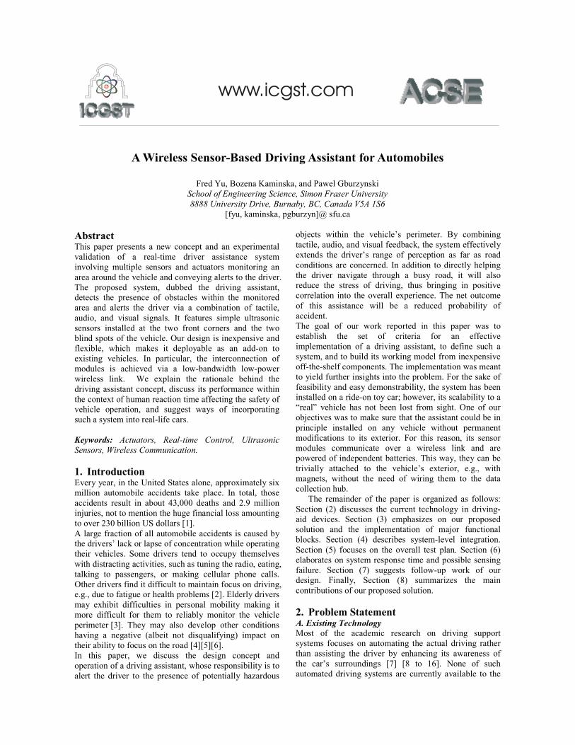
Figure 1 shows the correlation among the system
components. The sensor modules employ ultrasonic
sensors, while the controller connects to three types of
indicators: the LEDs panel, the buzzer, and the vibrators
mounted on the steering wheel.
A. The Sensors
The function of the sensor network is to detect objects
appearing in the four zones around the vehicle. Those
objects can be stationary (located on the side of the road),
e.g., trees or buildings, or mobile, such as other vehicles
or pedestrians.
The driving assistant detects objects in the monitored
areas via ultrasonic proximity sensors. Infrared and radar
sensors were considered as possible alternatives.
However, infrared sensors lack the accuracy of their
ultrasonic counterparts due to the ambient noise and
infrared radiation [23]. Radar sensors, on the other hand,
are expensive and complicated in use, because of the
need for CPU-intensive image processing techniques. In
addition to raising the project cost directly (by being
expensive themselves), they would also need a more
complex processing platform, which would also increase
the cost of their encasing sensor modules.
Consequently, we based our design on ultrasonic sensors,
specifically the PING)))TM sensors from Parallex [24].
Such a sensor is in fact a compound device consisting of
an ultrasonic emitter and the “proper sensor” whose role
is to detect the reflected signal sent by the emitter. The
device is triggered by a pulse from the microcontroller
forcing it to emit a 40 kHz burst to the environment.
Following the end of the burst, the microcontroller is
expected to measure the amount of time elapsing until the
arrival of the reflected signal, as perceived by the sensor.
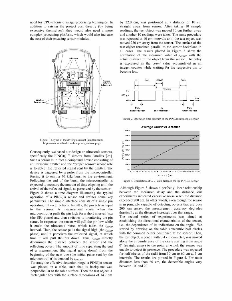
Figure 2 shows a time diagram illustrating the typical
operation of a PING))) sensor and defines some key
parameters. The simple interface consists of a single pin
operating in two directions. Initially, the pin acts as input
to the sensor. A measurement starts when the
microcontroller pulls the pin high for a short interval tTRIG
(the SIG phase) and then switches to monitoring the pin
status. In response, the sensor will pull the pin low while
it emits the ultrasonic burst, which takes the tHOLD
interval. Then, the sensor pulls the signal high (the tECHO
phase) until it perceives the reflected signal, at which
time it will pull the pin down. Thus, tECHO directly
determines the distance between the sensor and the
reflecting object. The amount of time separating the end
of a measurement (the signal going down) from the
beginning of the next one (the initial pulse sent by the
microcontroller) is denoted by tDELAY.
To study the effective detection range, a PING))) sensor
was placed on a table, such that its backplane was
perpendicular to the table surface. Then the test object, a
rectangular box with the surface dimensions of 14.7 cm
by 22.0 cm, was positioned at a distance of 10 cm
straight away from sensor. After taking 10 sample
readings, the test object was moved 10 cm further away
and another 10 readings were taken. The same procedure
was repeated at 10 cm intervals until the test object was
moved 230 cm away from the sensor. The surface of the
test object remained parallel to the sensor backplane in
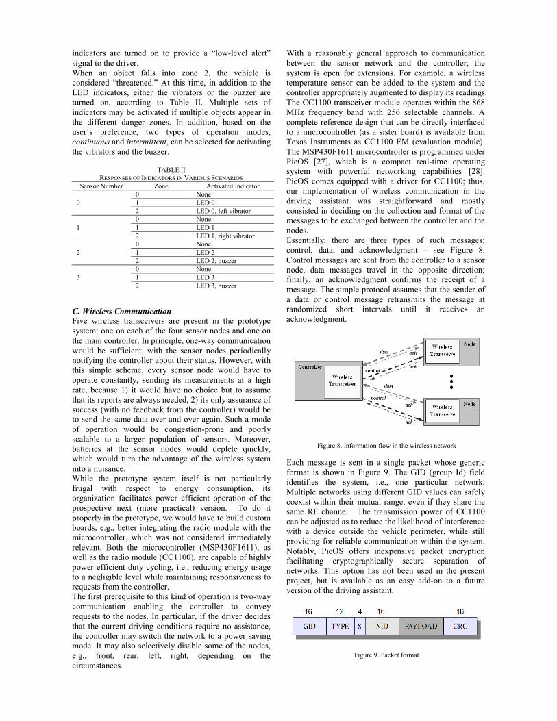
all cases. The results plotted in Figure 3 show the
correlation of the measured value of tECHO with the
actual distance of the object from the sensor. The delay
is expressed as the count value accumulated in an
integer counter while waiting for the respective pin to
become low.
Figure 2. Operation time diagram of the PING))) ultrasonic sensor
Figure 3. Correlation of tECHO with distance for the PING))) sensor
Although Figure 3 shows a perfectly linear relationship
between the measured delay and the distance, our
experiments indicated excessive noise when the distance
exceeded 200 cm. In other words, even though the sensor
is in principle capable of detecting objects that are over
200 cm away, the measurement accuracy degrades
drastically as the distance increases over that range.
The second series of experiments was aimed at
establishing the directional characteristics of the sensor,
i.e., the dependence of its indications on the angle. We
started by drawing on the table concentric half circles
with the common center positioned at the sensor. Then,
the test object, a pencil with 0.4 cm diameter, was moved
along the circumference of the circle starting from angle
0˚ (straight away) to the point at which the sensor was
unable to detect its presence. The procedure was repeated
for half circles of the radii from 10 cm to 60 cm at 5 cm
intervals. The results are plotted in Figure 4. For most
distances less than 60 cm, the detectable angles vary
between 10˚ and 20˚.
Figure 1. Layout of the driving assistant (adapted from:
http://www.suurland.com/blueprints_archive.php)

Figure 4. The directional characteristics of PING)))
Following our understanding of the performance of the
ultrasonic sensors, the next step involved making design
decision regarding the specific areas of sensor coverage.
The ride-on toy car used as the prototype model has a
width of approximately 60 cm. The area surrounding the
car was partitioned into three zones listed in Table I.
Each of the four targeted areas: the left blind spot, the
right blind spot, the left front corner and the right front
corner, was assigned one sensor module. Using the zone
designations from Table I and the results from Figure 4,
Figure 5 visualizes the areas of coverage for the entire
sensor network. The sensor numbering from Figure 5 will
be followed in the rest of the paper.
B. The Indicators
The goal of the indicators is to warn the driver about the
presence of a potential hazard. Three different indicators
were implemented in the prototype system: an LED
display panel, two tactile vibrators mounted on the
steering wheel, and a buzzer. Different indicators are
activated depending on the degree of hazard. All
indicators connect to and receive signals from the
controller.
The LED display is built of an off-the-shelf 5x8 LED
matrix shown in Figure 6. Four LEDs were assigned to
directly represent the status of the four ultrasonic sensors,
based on their position: they have been highlighted in
Figure 6. Thus, LED 0 corresponds to the status of the
left front corner sensor (sensor 0); LED 1 corresponds to
the right front corner sensors (sensor 1), and so on.
The vibrator motors used in the project are manufactured
by Jameco Electronics [25]. Their voltage/current
requirements make it possible to drive them directly from
the microcontroller, with no need for a power amplifier.
A vibrator may vibrate continuously or intermittently. In
the second case, the vibrations are produced in 2-second
spurts separated by 2-second breaks.
The audio signal is provided by the magnetic buzzer from
CUI Inc. [26] operating as shown in Figure 7. To trigger
the buzzer, a square wave of 2400 Hz frequency and 1-3
V amplitude should be fed to the circuit input. A
reasonable approximation of such a waveform is
generated by the microcontroller. Similar to the vibrator,
the buzzer can generate continuous and intermittent
sounds. In the latter case, the buzzer sounds five times,
each time for a duration of approximately 0.5 s.
Figure 6. The LED panel
Figure 7. The buzzer circuit
Of the three types of indicators, the vibrators and the
buzzer generate stronger and more direct stimuli than the
LED display. The driver should immediately hear the
buzz sound or feel the vibrations, as soon as a hazard is
present. LED flashes can only be perceived if the driver
looks directly at the display. Their role is to indicate the
specific location of the hazard.
For as long as no obstacles are present in zone 1 and zone
2, the vehicle is considered safe, and none of the
indicators are activated. When an object is present in
zone 1, the vehicle is considered only “mildly
threatened,” since the closest foreign object is half to one
vehicle width away. At this time, the respective LED
Figure 5. Coverage area for the ride-on toy car
TABLE I ZONE DESIGNATION
Zone Distance from car Number of car
widths Danger level
0 > 60cm > 1 safe
1 30cm – 60cm 0.5 - 1 mildly dangerous
2 < 30cm < 0.5 very dangerous
indicators are turned on to provide a “low-level alert”
signal to the driver.
When an object falls into zone 2, the vehicle is
considered “threatened.” At this time, in addition to the
LED indicators, either the vibrators or the buzzer are
turned on, according to Table II. Multiple sets of
indicators may be activated if multiple objects appear in
the different danger zones. In addition, based on the
user’s preference, two types of operation modes,
continuous and intermittent, can be selected for activating
the vibrators and the buzzer.
C. Wireless Communication
Five wireless transceivers are present in the prototype
system: one on each of the four sensor nodes and one on
the main controller. In principle, one-way communication
would be sufficient, with the sensor nodes periodically
notifying the controller about their status. However, with
this simple scheme, every sensor node would have to
operate constantly, sending its measurements at a high
rate, because 1) it would have no choice but to assume
that its reports are always needed, 2) its only assurance of
success (with no feedback from the controller) would be
to send the same data over and over again. Such a mode
of operation would be congestion-prone and poorly
scalable to a larger population of sensors. Moreover,
batteries at the sensor nodes would deplete quickly,
which would turn the advantage of the wireless system
into a nuisance.
While the prototype system itself is not particularly
frugal with respect to energy consumption, its
organization facilitates power efficient operation of the
prospective next (more practical) version. To do it
properly in the prototype, we would have to build custom
boards, e.g., better integrating the radio module with the
microcontroller, which was not considered immediately
relevant. Both the microcontroller (MSP430F1611), as
well as the radio module (CC1100), are capable of highly
power efficient duty cycling, i.e., reducing energy usage
to a negligible level while maintaining responsiveness to
requests from the controller.
The first prerequisite to this kind of operation is two-way
communication enabling the controller to convey
requests to the nodes. In particular, if the driver decides
that the current driving conditions require no assistance,
the controller may switch the network to a power saving
mode. It may also selectively disable some of the nodes,
e.g., front, rear, left, right, depending on the
circumstances.
With a reasonably general approach to communication
between the sensor network and the controller, the
system is open for extensions. For example, a wireless
temperature sensor can be added to the system and the
controller appropriately augmented to display its readings.
The CC1100 transceiver module operates within the 868
MHz frequency band with 256 selectable channels. A
complete reference design that can be directly interfaced
to a microcontroller (as a sister board) is available from
Texas Instruments as CC1100 EM (evaluation module).
The MSP430F1611 microcontroller is programmed under
PicOS [27], which is a compact real-time operating
system with powerful networking capabilities [28].
PicOS comes equipped with a driver for CC1100; thus,
our implementation of wireless communication in the
driving assistant was straightforward and mostly
consisted in deciding on the collection and format of the
messages to be exchanged between the controller and the
nodes.
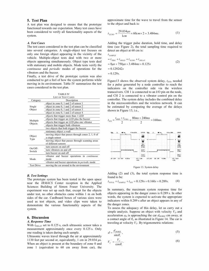
Essentially, there are three types of such messages:
control, data, and acknowledgment – see Figure 8.
Control messages are sent from the controller to a sensor
node, data messages travel in the opposite direction;
finally, an acknowledgment confirms the receipt of a
message. The simple protocol assumes that the sender of
a data or control message retransmits the message at
randomized short intervals until it receives an
acknowledgment.
Figure 8. Information flow in the wireless network
Each message is sent in a single packet whose generic
format is shown in Figure 9. The GID (group Id) field
identifies the system, i.e., one particular network.
Multiple networks using different GID values can safely
coexist within their mutual range, even if they share the
same RF channel. The transmission power of CC1100
can be adjusted as to reduce the likelihood of interference
with a device outside the vehicle perimeter, while still
providing for reliable communication within the system.
Notably, PicOS offers inexpensive packet encryption
facilitating cryptographically secure separation of
networks. This option has not been used in the present
project, but is available as an easy add-on to a future
version of the driving assistant.
Figure 9. Packet format
TABLE II
RESPONSES OF INDICATORS IN VARIOUS SCENARIOS
Sensor Number Zone Activated Indicator
0
0 None
1 LED 0
2 LED 0, left vibrator
1
0 None
1 LED 1
2 LED 1, right vibrator
2
0 None
1 LED 2
2 LED 2, buzzer
3
0 None
1 LED 3
2 LED 3, buzzer

Every packet ends with a 16-bit CRC code calculated
according to the ISO 3309 standard. Generally, the
interpretation of its remaining components depends on
the TYPE field. Intentionally, S provides a short (modulo
16) serial number field to be used for detecting missed
packets in a sequence and/or pairing acknowledgments
with their packets. TYPE zero identifies
acknowledgments.
All packets in our present application use the NID field to
indicate the node number to which the packet pertains.
For a control packet, this field contains the number of the
sensor node to which the packet is addressed. For a data
packet, the NID field identifies the sender (the packet is
implicitly addressed to the controller). For an
acknowledgment, NID relates to the sensor node
involved. That is, if the acknowledgment is sent by a
node, NID identifies the sender, if it is sent by the
controller, then NID refers to the node to which the
acknowledgment is addressed.
The payload field of a control packet (TYPE = 1)
contains two 16-bit values: tDELAY (see Figure 2) and the
number of readings per sample nr. Following the
reception of such a packet, the sensor node will begin
periodic measurements separated by tDELAY milliseconds.
After every nr distance measurements, the node will use
their average to assess the hazard according to Table I.
The node can be switched off by requesting nr = 0.
The payload of a data packet (TYPE = 2) carries the zone
report, i.e., 0, 1, or 2, encoded as a 16-bit integer. To
avoid unnecessary congestion, such a packet is only sent
if the report would be different from the previous one, i.e.,
something has changed. Note that data packets are
acknowledged: they are sent persistently until the node
makes sure that the controller has been informed. Thus,
there is no need to notify the controller unless the
situation has changed with respect to the previous
successfully conveyed report. Should the controller wish
to verify whether a particular node is operational, it can
do so with a control packet, which again will be
acknowledged by the node.
Acknowledgement packets (TYPE = 0) have no payload
(the PAYLOAD field is empty). They are matched to the
packets being acknowledged by the S field. A node
sending a data packet is expected to increment that field
by 1 (modulo 16) with every new report. Similarly, the
controller is expected to sequence its control packets in
the same way, on the per-node basis.
D. The Modules
Two types of modules are present in the system: the
nodes and the controller. The controller receives data
packets from the nodes, interprets their alerts, and
activates the proper response of the indicators. The
controller also receives direct commands from the driver
through a series of DIP switches integrated onto the
microcontroller board. The node modules receive control
packets from the controller, interpret its commands, carry
out their measurements, and report situation changes to
the controller. Figure 10 depicts the data flow within the
two types of modules.
All the modules of our prototype system have been built
of five identical MSP430F1611 development boards.
They have been programmed under PicOS [27], and they
run multi-threaded reactive applications (called praxes in
PicOS) to ensure that all commands are processed and all
responses are generated in real-time.
A status LED is present on each node board to indicate
whether the sensor is currently running or has been
stopped. Even though the ultrasonic sensors come with
their own LED indicators, those indicators are obscured
from the driver’s view by the mounting. The status LEDs
were useful for tests and debugging. A real-life version of
our system will need no such feature, as the status of a
sensor module can be reliably determined from the
controller.
Figure 10. Flow of data in the two types of modules
A set of DIP switches added to the controller module
offers a simple user interface to the system. For example,
the driver may want to disable some or all the sensors,
depending on the current driving conditions. It is also
possible to switch off some of the indicators, e.g., the
buzzer, or select the vibrator mode (continuous versus
intermittent).
4. System Integration The prototype system was installed on a ride-on toy car
for demonstration and validation. The dimensions of the
car are roughly 85 cm long and 60 cm wide. The
controller was placed on the dashboard, with the
vibrators mounted on the steering wheel. For the ease of
mounting and adjustments, the sensors were separated
from their modules and connected with wires: the
modules were placed inside the car, while the sensors
were attached to the exterior at the height of about 35 cm
from the ground. The fully equipped car is shown in
Figure 11. Table III provides the complete list of parts.
Figure 11. The prototype car

A. Power Circuits
During the development stage, all the components,
circuits and microcontrollers were powered from
adaptors connected to the power outlet. To allow the
system to be installed on the toy car and freely moved
along with it, portable power supplies were built.
For each node, two output voltage levels, 3.3 V and 5V,
are generated in the power circuit. While 3.3 V is used to
power the MSP430F1611 microcontroller and most
components on the node, 5V is needed by the PING)))
ultrasonic sensor. As a result, the power circuit consists
of a 5V and a 3.3 V voltage regulator connected in
parallel. One has to notice that this is a rather serious
disadvantage from the viewpoint of power-efficient
operation of the wireless sensor node, as each regulator
incurs unavoidable losses. However, there exist
ultrasonic sensors operating at 3.3 V, e.g., the LV-
MaxSonarTM
range finder from MaxBotic. Notably, the
range of that sensor is over 6 m, which makes it better
suited for deployment in a realistic vehicle. With the
unification of voltage requirements, the regulators can be
completely eliminated. This is possible because the
microcontroller, the RF module, as well as the low-
voltage ultrasonic sensor exhibit comfortable tolerance
regarding the range of supply voltage, with the lower
bound around 2.5V.
Figure 12 shows the power circuit for the sensor node.
The bypass capacitor C3 filters out the addition noise. In
the controller, the power circuit is simpler, since only a
single 3.3 V voltage level is required to power the
microcontroller and all the components.
Figure 12. The power supply circuit for the node
B. The Software
The software for the controller and the nodes consists of
two PicOS applications (praxes) organized into
multithreaded programs. In the controller, the root
process (which in a PicOS praxis plays the role of “main
program”) coordinates the activities of three child
processes: sender, receiver, and actuator. The sender
process is only created if a control packet has to be sent
out and remains active until the last outstanding control
packet has been acknowledged by the recipient. The
process runs automatically on startup to initialize the
sensor nodes; then it is invoked by actuator whenever the
parameters of a sensor node should change.
The receiver process receives data and acknowledgement
packets from the nodes and sends out acknowledgement
packets to the nodes to confirm the receipt of data
packets. The process operates in an infinite loop and
continuously expects to receive incoming packets.
The actuator process controls the operations of the three
indicators: the LED display, the vibrators and the buzzer.
The process also continuously monitors the status of the
DIP switches. Data packets received by receiver update
the global variables to indicate the most recent status of
the sensors. The process operates in an infinite loop,
reading the global variables in every iteration and
updating the indicators accordingly to match the current
status of the sensors.
All nodes run exactly the same program, which differs by
a single constant at every node: the node Id (0 – 3, see
Figure 5). Having initialized the module, the root process
creates one child process, receiver, which remains active
for as long as the node is powered up. The receiver
process receives control packets and acknowledgements
from the controller. It also sends out acknowledgment
packets to the controller to confirm the receipt of control
packets. If, based on the controller’s request, the node is
to be active, i.e., it has to carry out its sensing duties,
receiver creates an additional process, named sensor,
whose role is to perform the measurements and report
zone alerts to the controller. During its lifetime, the
sensor process continuously triggers the ultrasonic sensor
and measures the value of tECHO (see Figure 2). If the new
sample shows that the zone of the closest foreign object
has changed, the sensor process creates and sends out a
data packet addressed to the controller.
TABLE III
COMPLETE PART LIST
Component Manufacturing # Quant.
Microcontroller Development
Board MSP430F1611 5
PING)))TM Ultrasonic Sensor Parallax Inc. 4
Ride-on Toy Car 1
LED Matrix (5X8, Red) 1
Buzzer (2.4 kHz) CEM-1201S 1
Diode 1
NPN Transistor 2N3904 1
Vibrator Motor (3V, 75mA,
8500 rpm) 6ZK053 2
Wireless Module CC1100EMK868-
915 5
Antenna CC1100EMK868-
915 5
Connectors 852-10-100-10-
001000 2
Battery Holder (9V, Wire
Leads) 5
Alkaline Battery (9V) 5
Voltage Regulator (+5V, 1A) 7805UC 4
Voltage Regulator (3.3V) LT1086CT 5
Tantalum Capacitor (10µF,
10V) 15
Ceramic Capacitors (0.33µF,
50V) C320C334M5U5TA 4
Ceramic Capacitors (0.47µF, 50V)
C322C474M5U5TA 4
LED (Green, Clear) LTL-4238 4
DIP Switch (Rocker, Sealed, 2
Positions) 76SB02ST 1
DIP Switch (Rocker, Sealed, 4 Positions)
76sB04ST 5
Resistor (150 Ω) 1
Resistor (4.7 kΩ) 4
Wood Blocks 5
5. Test Plan A test plan was designed to ensure that the prototype
functioned towards our expectation. Many test cases have
been considered to verify all functionality aspects of the
system.
A. Test Cases
The test cases considered in the test plan can be classified
into several categories. A single-object test focuses on
only one foreign object appearing in the vicinity of the
vehicle. Multiple-object tests deal with two or more
objects appearing simultaneously. Object type tests deal
with stationary and mobile objects. Mode tests verify the
continuous and periodic modes of operations for the
vibrators and the buzzer.
Finally, a test drive of the prototype system was also
conducted to get a feel of how the system performs while
moving in its environment. Table IV summarizes the test
cases considered in the test plan.
B. Test Settings
The prototype system has been tested in the open space
near the IRMACS Center reception in the Applied
Sciences Building of Simon Fraser University. The
experiment was set up such that, except for the objects
under test, no other obstacles came within 1 m on both
sides of the car. Cardboard boxes of various sizes were
used as test objects, and video clips were taken to
demonstrate the various functionality aspects of the
system.
6. Discussion A. Response Time
With tDELAY set to 0.125 s, each ultrasonic sensor takes a
measurement approximately once every 0.125 s. Only
one reading is taken during each sample.
Ultrasonic waves travel through the air at approximately
1130 feet per second or, equivalently, 1 cm in 29.034 µs.
When an object is present at the boundary of zone 0 and
zone 1 (equivalent to 60 cm away from car), the
approximate time for the wave to travel from the sensor
to the object and back is:
.484.32601
034.29mscm
cm
st ECHO =××=
µ (1)
Adding the trigger pulse duration, hold time, and delay
time (see Figure 2), the total sampling time required to
detect an object at 60 cm is:
.129.0
129242.0
125.0484.37508
s
s
smsss
tttt
t
DELAYECHOHOLDTRIG
SAMPLE
=
=
+++=
+++=
µµ (2)
Figure13 shows the observed system delay, tSYS, needed
for a pulse generated by a node controller to reach the
indicators on the controller side via the wireless
transceivers. CH 1 is connected to an I/O pin on the node,
and CH 2 is connected to a vibrator control pin on the
controller. The system delay includes the combined delay
in the microcontrollers and the wireless network. It can
be estimated by computing the average of the delays
shown in Figure 13, i.e.,
.1602
24080
2ms
msmsttt FALLRISE
SYS =+
=+
= (3)
Figure 13. System delay
Adding (2) and (3), the total system response time is
found to be:
.289.0160.0129.0 sssttt SYSSAMPLETOTAL =+=+= (4)
In summary, the maximum system response time for
objects appearing in the danger zones is 0.289 s. In other
words, the system is expected to activate the appropriate
indicators within 0.289 s after an object appears in any of
the danger zones.
To assess the adequacy of this delay, let us carry out a
simple analysis. Suppose an object with velocity VO and
acceleration aO is approaching the car dHORIZ cm away, at
a contact angle of θi, as illustrated in Figure 14. The car is
traveling at velocity VC. By trigonometric relations:
,sin i
HORIZdd
θ= (5)
.cos
'
i
C
C
VV
θ= (6)
TABLE IV
LIST OF TEST CASES
Category Description
Single Object
object in zone 0, 1 and 2 of sensor 1
object in zone 0, 1 and 2 of sensor 2
object in zone 0, 1 and 2 of sensor 3
object in zone 0, 1 and 2 of sensor 4
Multiple
Objects
objects that trigger more than 1 LED
objects that trigger an LED plus the buzzer
objects that trigger an LED plus one vibrator
objects that trigger both vibrators
two objects that both trigger the buzzer
Object
Type
stationary object: a wall
moving object that passes through zones 2, 1, 0 of
a single sensor
moving object that passes through scanning areas of different sensors
On/Off-Switch
turn sensors on and off
turn vibrators on and off
turn buzzer on and off
Mode
vibrator and buzzer operations in continuous mode
vibrator and buzzer operations in periodic mode
Test Drive moving the car around in the environment

Figure 14. Geometric relation between the car and an approaching
object
The time t until the object hits the car is determined
using the kinematics relation:
.2
1 2'tatVtVd OOC +=+ (7)
Thus, t is also the amount of time available for the system
to react to the approaching object. Rearranging the terms
and solving for time, we get:
( ) ( ).
22''
O
OCOOC
a
daVVVVt
+−±−= (8)
Since the negative term is not applicable, (8) boils down
to:
( ) ( ).
22''
O
OCOOC
a
daVVVVt
+−+−= (9)
By plugging various sets of VO, VC, aO, θi, and dHORIZ into
(5), (6) and (9) we can obtain the respective t. For
simplicity, dHORIZ is fixed at 60 cm because the prototype
system considers any distance less than 60 cm as
dangerous and starts issuing warnings to the driver. Also,
the car is assumed to travel at the typical speed of 60
km/h.
The actual system response time given by (4) is
compared against the allowable system response time
obtained from (5), (6), and (9). The actual system
response time is found to be shorter in most cases.
Therefore, the indicators are triggered before the
approaching object strikes the vehicle. Table V shows the
maximum object velocity the system is capable of
handling at various contact angles and under various
accelerations.
Table V can be interpreted as follows. For an object
traveling at a contact angle of 2.5°, 5.0° and 7.5° and an
acceleration of 4.0 m/s2 or less, the indicators are
activated ahead of collision if the object velocity is less
than 110 km/h. For an object traveling at a contact angle
of 10.0° and an acceleration of 4.0 m/s2 or less, the
indicators are activated ahead of collision if the object
velocity is less than 100 km/h. For an object traveling at a
contact angle of 20.0° and an acceleration of 4.0 m/s2, the
indicators are activated ahead of collision if the object
velocity is less than 80 km/h.
Table V shows that the system is able to react to
approaching objects in a timely manner, even though the
cases considered in the table are rather extreme. Since
objects traveling at a large contact angle (more than 10°)
and high acceleration (over 3.0 m/s2) are extremely rare
in real traffic, the system performance is deemed
adequate for handling the majority of hazardous
situations on the road.
B. Failures Occasionally, the indicators may fail to provide the
correct representation of the area around the vehicle. An
indicator may remain deactivated when it should have
been activated, or it may be activated when it should
remain silent. The former case is usually more serious
because it puts the vehicle at risk.
Several problems may affect the operation of the driving
assistant. For example, packet congestion in the wireless
channel may delay the receipt of a data packet. Other
ultrasonic waveforms and noise signals present in the
environment may affect sensor readings. The type of
surface of the intruding object may also influence the
reflectivity of ultrasonic waves.
No driving aid system can be 100% foolproof.
Considering the possibility of failure, the system should
only be used as an assistant rather than a substitute for
staying alert, maintaining safety distance, performing
mirror and shoulder checks, etc.
7. Future Work As the first design of the driving assistant, the prototype
system has room for improvement in several areas.
A. Sensor 'etwork
The number of ultrasonic sensors in the sensor network
can be increased to provide better coverage around the
vehicle. In particular, the rear end and the front of the car
require some form of scanning in addition to the blind
spots and the two front corners covered by the current
system. Furthermore, numerical analysis techniques may
be applied to filter out erroneous readings and reduce the
effect of noise in the sensor measurements. Also, instead
of using off-the-shelf components, device-specific
TABLE V
MAXIMUM ALLOWABLE OBJECT VELOCITY
Maximum Object
Velocity (km/hr)
Contact Angle (deg)
2.5 5.0 7.5 10.
0
15.
0
20.
0
Object
Acceleration
(m/s2)
0.00
1
110
+
110
+
110
+ 90 90 85
0.5 110
+
110
+
110
+ 90 90 85
1.0 110
+
110
+
110
+ 90 90 85
1.5 110
+
110
+
110
+ 90 90 80
2.0 110
+
110
+
110
+ 85 85 80
2.5 110
+
110
+
110
+ 85 85 80
3.0 110
+
110
+
110
+ 85 85 80
3.5 110
+
110
+
110
+ 85 85 80
4.0 110+
110+
110+
85 85 80

sensors can be designed and manufactured for use in the
driving assistant.
Our experiments have indicated that the wireless network
is a reliable medium for the type of system represented
by our driving assistant. In particular, we have never
experienced congestion problems resulting in prolonged
packet loss that would affect the real-time status of an
alert. This is because the alert notifications (in their
present form) pose little demand for bandwidth. However,
the situation may change when more sensors are added to
the network, especially if the data sent by those sensors
are more complicated than sequences of simple numbers.
Note that any numerical processing should be done in the
controller rather than the node. This is because 1) the
controller is less power-constrained, 2) the processing
capabilities can be centralized in one place, which will
reduce the cost of the whole system. This approach,
however, may increase the bandwidth required to convey
the raw data to the controller and bring about congestion.
Notably, the present communication protocol is open for
natural improvements. First of all, considering the short
distance of communication, the transmission rate can be
increased (up to about 100 kbps for CC1100). Second, a
TDMA scheme can be employed to guarantee bandwidth
for critical nodes. The proper design clearly depends on
the content and frequency of the requisite messages, but
it appears feasible under all conceivable circumstances.
Another advantage of the wireless sensor network is its
futuristic provision for communication among different
vehicles. By announcing and possibly synchronizing their
maneuvers, multiple vehicles sharing the road may be
able to arrive at a better social behavior, which would
clearly translate into a reduced likelihood of collisions.
B. Indicators A more elegant way of implementing the vibrators on the
steering wheel would be to design a special fabric that
produces tactile stimuli. The entire steering wheel can be
wrapped with such a fabric, so the drivers may grip on
any portion of the steering wheel, using one hand or both
hands, and still feel the stimuli.
8. Conclusion Starting from conceptualizing, designing, building to
finally presenting, we have designed a driving assistant
system which could be a possible solution for accident
prevention. Three innovative features are characteristic of
the prototype design discussed in this paper. First, an
ultrasonic sensor system is implemented to detect foreign
objects in areas around the blind spots and the front
corners of the vehicle. Our experiments show that the
low-cost PING)))TM
ultrasonic yield satisfying accuracy
in distance measurement. Secondly, an LED display,
tactile vibrators, and a buzzer are introduced as the
enhanced indicator design, which provides different
levels of hazard warnings to the vehicle driver. Finally, a
proprietary operating system, PicOS, and wireless
interface, from Olsonet Communications Corporation,
are evaluated and adapted in this project.
The final prototype design meets all the proposed
functionalities of the new driving assistant. In addition,
the control switches that are added to the main controller
further make the design user-friendly. The underlying
software is structured so that many more sensor nodes
can be easily integrated into the system. Finally, the work
of this project can be further expanded to evaluate the
traffic pattern of multiple vehicles, which may potentially
become a valuable asset for future studies in traffic
control and accident prevention.
9. References [1] Car Accidents.com. (2006). Car Accident Stats.
[Online]. Available: http://www.car-
accidents.com/pages/stats.html
[2] J. Lyznicki, et al. “Sleepiness, Driving, and Motor
vehicle Crashes,” JAMA, vol. 279, no. 23, 1998, pp
1908-1913.
[3] S. Shaheen, D. Niemeier. “Integrating Vehicle
Design and Human Factors: Minimizing Elderly
Driving Constraints,” Transportation Research Part
C: Emerging Technologies, vol. 9, no. 3, 2001, pp.
155-174.
[4] J. Duchek et al. “Attention and Driving
Performance in Alzheimer’s Disease,” Journals of
gerontology Series B: Psychological Sciences and
Social Sciences, vol. 53, no. 2, 1998, pp. 130-141.
[5] C. Owsley. “Vision and Driving in the Elderly,”
Optometry and Vision Science, vol. 71, no. 12,
1994, pp. 727-735.
[6] R. Kington et al. “Sociodemographic and Health
Factors in Driving Patterns after 50 Years of Age,”
American Journal of Public Health, vol. 84, no. 8,
1994, pp. 1327-1329.
[7] H. Nagel, W. Enkelmann, G. Struck. “FhG-Co-
Driver: from Map-Guided Automatic Driving by
Machine Vision to a Cooperative Driver Support,”
Mathematical and Computer Modelling, vol. 22, no.
4, 1995, pp. 185-212.
[8] M. Bertozzi et al. “Stereo Vision-Based Vehicle
Detection,” Proceedings of Intelligent Vehicles
Symposium, Dearborn, MI, 2000, pp. 39-44.
[9] M. Parent et al. “Automatic Driving in Stop and Go
Traffic,” Proceedings of Intelligent Vehicles
Symposium, Oct. 24-26, 1994, pp. 183-188.
[10] J. Borenstein and Y. Koren, “Obstacle Avoidance
with Ultrasonic Sensors,” IEEE Journal of Robotics
and Automation, Vol. 4, No. 2, pp 213-218, Apr.
1988
[11] R. Bishop, “A Survey of Intelligent Vehicle
Applications Worldwide,” in Proc. Of the IEEE
Intelligent Vehicles Symposium 2000, Oct. 3-5,
2000, Dearborn, MI, USA
[12] K. Song, C. Chen, and C. C. Huang, “Design and
Experimental Study of an Ultrasonic Sensor System
for Lateral Collision Avoidance at Low Speeds,”
2004 IEEE Intelligent Vehicles Symposium, June
14-17, 2004, Parma, Italy
[13] D. B. Lulu, “Vehicle Alarm System,” U.S. Patent
5,583,495, Dec. 10, 1996
[14] H. Jula, E. B. Kosmatopoulos, and P. A. Ioannou,
“Collision Avoidance Analysis for Lane Changing
and Merging,” IEEE Transactions on Vehicular
Technolog, Vol. 49, No. 6, pp 2295-2308, Nov.
2000

[15] M. Klotz and H. Rohling, “24 GHz Radar Sensors
for Automotive Applications,” 13th International
Conference on Microwaves, Radar and Wireless
Communications, pp 359-362, 2000
[16] K. Schofield and N. R. Lynam, “Vehicle Blind Spot
Detection Display System,” U.S. Patent 5,929,786,
Jul. 27, 1999.
[17] Backup-Sensor.com. (2006). How It Works.
[Online]. Available: http://www.backup-
sensor.com/parking_sensor.html
[18] Valeo Management Services. (2005). Blind Spot
Detection System. [Online]. Available:
http://www.valeo.com/automotive-
supplier/Jahia/pid/1034
[19] Xilinx, Inc. (2005, January 19). Haptic Feedback
Indication for a Blind-Spot Detection System.
[Online]. Available:
http://direct.xilinx.com/bvdocs/appnotes/xapp435.p
df
[20] Institute of Communications and Computer Systems.
(2005). Integrated Drivers’ Lateral Support System:
The Lateral Safe Project. [Online]. Available:
http://www.preventip.org/download/Events/200506
01%20ITS%20Hannover%20papers/2683.pdf
[21] L. Andreone et al. “A New Driving Supporting
System Integrating an Infrared Camera and an Anti-
Collision Microwave Radar: the EUCLIDE
Project,” Proceedings of IEEE Intelligent Vehicle
Symposium, June, 2002, pp. 519-526.
[22] N. Sueharu et al. “A Study of the Driving Support
System Based on Driver’s Behavior Analysis,”
Journal of the Society of Automotive Engineers of
Japan, vol. 57, no. 12, 2003, pp. 102-107.
[23] Migatron Corp. (2005). Frequently Asked Questions
About Ultrasonic Technology. [Online]. Available:
http://www.migatron.com/overview.htm
[24] Parallax Inc. (2006). PING)))TM Ultrasonic Sensor.
[Online]. Available:
http://www.parallax.com/dl/docs/prod/acc/28015-
PING-v1.3.pdf
[25] Jameco Electronics. (2006). 3.0VDC 8500 RPM
Vibrating Motor. [Online]. Available:
http://www.jameco.com/Jameco/Products/ProdDS/2
56313.pdf
[26] CUI Inc. (2006). Magnetic Buzzer. [Online].
Available: http://www.cui.com/pdffiles/CEM-
1201S.pdf
[27] E Akhmetshina, P. Gburzynski, F. Vizeacoumar.
“PicOS: A Tiny Operating System for Extremelly
Small Embedded Platforms,” Proceedings of
ESA’03, Las Vegas, June 23-26, 2003, pp. 116-122.
[28] P. Gburzynski, B. Kaminska, W. Olesinski. “A Tiny
and Efficient Wireless Ad-hoc Protocol for Low-
cost Sensor Networks,” Proceedings of DATE’07,
Nice, France, April 2007, pp. 1562-1567.
[29] Digi-Key Corporation. (2006). LED, Dot Matrix
Displays. [Online]. Available:
http://dkc3.digikey.com/PDF/C071/2079.pdf
Fred Yu received his B.A.Sc. (Honors)
degree in Electronics Engineering from
Simon Fraser University, Canada, in
2007. He is currently working toward a
M.S. degree in Electrical and Computer
Engineering at University of California,
San Diego. His area of concentration is
Electronic Circuits and Systems. His research interests
include VLSI, digital circuits and wireless
communication. From 2005 to 2006, he did a one-year
internship at Nippon Telegraph and Telephone, Japan.
Then, he joined Centre for Integrative Bio-Engineering
Research in Simon Fraser University and worked as an
undergraduate research assistant. In the summer of 2008,
he worked as an Intern Engineer at Qualcomm Inc., San
Diego, CA.
Bozena Kaminska, Ph.D., has 30 years
of academic and corporate experience as
a researcher, engineer, entrepren-eur
and educator. She is presently Professor
and Canada Research Chair in Wireless
Sensor Networks at Simon Fraser
University, focusing on the research and
development of new sensors and medical microsystems.
Kaminska is a prolific inventor, having authored multiple
patents and more than 200 IEEE peer-reviewed
publications in top scientific journals and conference
proceedings.
Pawel Gburzynski received his MSc
and PhD in Computer Science from
the University of Warsaw, Poland in
1976 and 1982, respectively. Before
coming to Canada in 1984, he had
been a research associate, systems
programmer, and consultant in the
Department of Mathematics,
Informatics, and Mechanics at the University of Warsaw.
Since 1985, he has been with the Department of
Computing Science, University of Alberta, where he is a
Professor. Dr. Gburzynski's research interests are in
communication networks, embedded systems, operating
systems, simulation, and performance evaluation.