A Weak Current Amperometric Technique in …...A Weak Current Amperometric Technique in...
20
Running Title: A Weak Current Amperometric Technique Title: A Weak Current Amperometric Technique in Physiological Measurement M. H. S. Bukhari *1, 2 , J. H. Miller, Jr. 1 and Z. H. Shah 3 1 Department of Physics, University of Houston, Houston, Texas 77204, USA 2 Unit of Experimental Physiology & Biophysics, Department of Physiology, Dow University of Health Sciences, Karachi-74200, Pakistan 3 Department of Chemistry, Lasbela University, Uthal, Lasbela 90150, Balochistan, Pakistan Abstract A technique for measuring ultra-low currents from living cells, using electrodes, biosensors or magnetic detectors is reported, based on the design of a sensitive, ultra-low-noise trans- impedance amplifier. This technique offers a low-noise, low current measurement capability down on the order of 2 x 10 -14 amperes, with specifications such as input leakage current of less than 1 x 10 -15 amperes and a dynamic range of 30-100 x 10 -14 amperes. Maximum bandwidth of roughly 10KHz was observed, while working in the specified dynamic range. This set of specifications is quite satisfactory and desirable for many low-frequency applications in cell/organelle electrophysiology and bio-amperometry. The technique finds many applications in studying low-frequency intrinsic fields and induced currents originated in cells. A few applications envisaged for its utility include ion transport studies in plasma membrane and mitochondrial inner membrane, membrane electrophysiology and bio-sensing amperometry, by incorporation of the amplifier with suitable micro- or nano-scale electrical/magnetic sensors. Keywords: intrinsic currents, biosensors, amperometry, electrophysiology * Corresponding Author. E-mail: [email protected] 2 Present Address - 1 -
Transcript of A Weak Current Amperometric Technique in …...A Weak Current Amperometric Technique in...

Running Title: A Weak Current Amperometric Technique Title: A Weak Current Amperometric Technique in Physiological Measurement
M. H. S. Bukhari*1, 2, J. H. Miller, Jr. 1 and Z. H. Shah3
1Department of Physics, University of Houston, Houston, Texas 77204, USA 2Unit of Experimental Physiology & Biophysics, Department of Physiology, Dow University of Health
Sciences, Karachi-74200, Pakistan 3Department of Chemistry, Lasbela University, Uthal, Lasbela 90150, Balochistan, Pakistan
Abstract
A technique for measuring ultra-low currents from living cells, using electrodes, biosensors or
magnetic detectors is reported, based on the design of a sensitive, ultra-low-noise trans-
impedance amplifier. This technique offers a low-noise, low current measurement capability
down on the order of 2 x 10-14 amperes, with specifications such as input leakage current of less
than 1 x 10-15 amperes and a dynamic range of 30-100 x 10-14 amperes. Maximum bandwidth of
roughly 10KHz was observed, while working in the specified dynamic range. This set of
specifications is quite satisfactory and desirable for many low-frequency applications in
cell/organelle electrophysiology and bio-amperometry. The technique finds many applications in
studying low-frequency intrinsic fields and induced currents originated in cells. A few
applications envisaged for its utility include ion transport studies in plasma membrane and
mitochondrial inner membrane, membrane electrophysiology and bio-sensing amperometry, by
incorporation of the amplifier with suitable micro- or nano-scale electrical/magnetic sensors.
Keywords: intrinsic currents, biosensors, amperometry, electrophysiology
* Corresponding Author. E-mail: [email protected] 2 Present Address
- 1 -
1. Introduction
A large number of important measurement applications in physiology, such as living cell
electrophysiology and bio-sensing with the help of embedded nanotechnology, require extremely
sensitive and ultra-low-noise current measurement techniques, which can measure tiny currents at
the levels of pico-amperes to femto-amperes. These measurements are typically made with micro-
electrodes, quantum devices and detectors, and low-temperature cryogenic Superconducting
Quantum Interference Device (SQUID) detectors, or SQUID-based nanotubes (Cleuziou et al.
2006). Various electrophysiological studies with ion channels (Hamill et al. 1981) or
investigations on intrinsic currents (Axmacher and Miles 2004) or weak electrical field processes
within living cells (Bullock 1987) also require sensitive instrumentation and amplification at the
level of femto-amperes to pico-amperes input current. Pico-ampere amplifiers are widely
available and can be easily fabricated on an electronics workbench in a physiological laboratory.
Unfortunately, techniques to measure ultra-low-current (such as on the level of femto-amperes)
cellular signals with least noise susceptibility are neither easy to develop nor widely available in
market, in view of the special design and fabrication considerations required for their
development. The main impediments faced in such designs are leakage of tiny input bias currents
through the amplifier circuitry and the inherent large noise associated with measurement of ultra-
low currents. With the help of special design and fabrication measures one can venture down to
an order of about 2-10 femto-amperes (with considerable noise reduction), while keeping the
leakage current to a minimum extent, not affecting the measurement in a significant way. Going
beyond that domain becomes an impervious task for in-house development, as, at first, there are
no general-purpose operational amplifiers available in market which can sense lower bias currents
beyond that range, and secondly, various terrestrial and celestial effects (such as ambient
electromagnetic fields in the vicinity and cosmic ray–induced electron shower events) induce tiny
currents in the front-end section of the amplifier, creating unavoidable current leakages.
Industrial-grade commercial pico- and femto-ampere measurement instruments are
available in market, but unfortunately they are an expensive modality and beyond the range of
budgets of small biophysics and physiology labs, especially in colleges with limited budgets.
Buying a commercial product off-the-shelf also precludes the experimenters from making
alterations or customizations in the device, in view of their specific applications. A small-scale
biophysical or physiological research laboratory has to thus rely on in-house designs.
- 2 -

There are some public-domain designs available for low-level biological signal voltage
and current amplifiers, as published extensively in literature, such as instrumentation amplifiers
and pico-ampere meters for electrophysiology applications and electrometers, but there are a
number of problems with these designs. First of all, most of the designs are for voltage mode
meters. Secondly, if there are few current amplifier designs published, they are limited to nano-
amperes or pico-amperes range, not presenting a design which can venture down to femto-
amperes. These design ideas also pose limitations in terms of keeping the signal integrity
conserved. Most importantly, these designs do not present special considerations and techniques
entailed to measure ultra-low-level signals while limiting the leakage currents and inherent noise
which are coupled to small-current measurements. Thus, availability of a mere design, such as by
an amplifier chip’s manufacturer specifications sheet, is not sufficient to implement it in practical
application.
In a biophysical and electrophysiological study by authors to investigate the possibility
and manifestations of intrinsic electric currents in living cell systems, it was undertaken to design
and fabricate a sensitive current to voltage converting amplifier which could successfully and
efficiently present a practical design of an ultra-low-current and ultra-low-noise trans-impedance
amplifier.
The design of this technique and its constituent amplifier differs from other conventional
techniques and amplifiers in a number of ways. First of all, it presents a design paradigm which
can venture down to a few tens of femto-amperes, while minimizing the leakage current and
noise, with the help of its careful choice of components and special considerations followed while
the fabrication of the device. Secondly, instead of just showing a way to measure the induced
field currents from applied potentials, it presents a technique for low-current measurement from
the living cells, which attempts to measure low-frequency intrinsic electric fields and induced
femto-ampere currents, produced as a result of intrinsic effects inherent within the cell plasma
membrane. This is done in an electromagnetically shielded environment and in the absence of
applied fields. Third, the amplifier and measurement technique can be developed in a small
laboratory in a very limited budget, costing even less than the cost of an average Digital
Multimeter (DMM).
This technique offers an enhanced accuracy in cell amperometry or electrophysiology
studies by the virtue of an improvement in its meticulous design and development. Design of the
- 3 -

amplifier is made on a special glass fiber board (instead of a conventional Printed Circuit Board,
PCB) and components (including the amplifier integrated circuits) are mounted on teflon stand-
offs using special considerations, as summarized in the next section. Noise susceptibility and
current leakage paths are kept to a very minimum. Usage is made of some of the most precision
components available in market, conserving the precision and signal integrity. The operational
amplifier device used in this design, National LMP7721, has a few excellent specifications,
especially the large error rejection capabilities while its use with giga-ohm value feedback
resistances, as we have incorporated in the design. The constructed amplifier prototype is
enclosed in a shielded miniature aluminum box and mounted on the micro-manipulator arm on
the microscope stage, and the input of the amplifier is directly connected to the cell electrode via
a short 90μ wire, without using any cable or connectors. This eliminates the noise and signal
losses in the cable communicating the signal from cells to the amplifier and to the data acquisition
stage. Thus, adoption of special measures and extensive trials have resulted into a design which
has lower current measurement range and higher accuracy and precision in terms of measurement
and signal integrity, as compared to designs published in literature.
2. Materials and Methods
2.1 Amplifier Design
The design of this amplifier comprises two stages and is built around a recently-introduced
precision operational amplifier IC (Integrated Circuit), National Semiconductors LMP7721. The
design reported in this paper is based on meticulous modification of a basic design as per the
manufacturer’s specifications (National Semiconductors, 2008). This device is an ultra-low-noise,
ultra-low input bias current, operational amplifier, manufactured with a MOS (Metal Oxide
Silicon) technology input stage. It has one of the lowest input bias current operations available in
market, guaranteed by manufacturer after extensive testing at around 3 x 10-15A. Moreover, it
offers superior noise performance, tested by manufacturer at 10fA-Hz-1/2 @ 1KHz and 7nV-Hz-1/2
@ 1KHz input-referred current and voltage noise, respectively, and a total harmonic distortion
(THD) of 0.003% @ 1KHz, as claimed by the manufacturer. Its one of the most important
features is curtailing of the magnitude of error produced when used with a large-value resistance,
such as giga-ohms. It suppresses the large error by a factor of about 103 to 106, a great advantage
in femto-ampere level current measurement using a high-value feedback resistor. This is a major
advantage of this device, which became the reason for our choosing its utility in this application,
in addition to its low bias current and low noise spectral density. In addition, a theoretical (open-
- 4 -

loop) Gain Bandwidth Product (GBP) of 17MHz and average slew rate of around 10.0V/μs, as
claimed in the manufacturer’s specifications for LMP7721 in its data sheet (National
Semiconductors 2008), are appropriate for applications in electrophysiology and general
biophysics (although, it should be noted that, practically, the theoretical GBP described above is
neither achievable in an ultra-low current amplifier design nor it is applicable in the design
presented here).
Design of the amplifier is illustrated in the circuit diagram in Figure 1. The first stage
comprises a unity gain current to voltage amplifier with a zero-resistance front-end, followed by
the second stage, a (approximate) gain of twenty inverting amplifier. The input signal is presented
via a 50GΩ Input Resistor to the inverting input of U1, LMP7721 device. This resistor is only
used for testing purposes to measure the minimum current readable by the amplifier. Once the
amplifier is tested, this resistor is removed, enabling a direct zero-resistance connection between
the input terminal and the amplifier. A precision resistor of 50GΩ is connected as the Feedback
Resistor to provide roughly 1010 current/voltage transfer function. However, the voltage gain of
the amplifier remains unity.
Figure 1: A schematic of the amplifier circuit
Output from the current/voltage pre-amplifier is passed on to a second amplification
stage, comprising of the U2 (LMP7721) via C3, which removes the DC voltage presented at the
output of U1 from the input current. U2 has a feedback resistor, R3, which can be of any value
close to around 1MΩ (an optimal value for our application was found to be 997KΩ), however a
higher resistance than 1.1MΩ was found to be unsatisfactory. This stage yields a voltage gain of
roughly x10 to x40 for the second amplifier (depending on the value of R3). Capacitor C5
prevents coupling of the amplifier to mains noise and also acts as a pseudo-cut-off for the high
frequency content of input signal. A successive power supply filtering scheme is adopted for the
amplifier power rails by means of numerous 10nF and 100nF capacitors at the power rail
employed in the circuit. In addition, a notch filter design can also be devised at this stage for
elimination of mains and high-frequency noise components. However, we did not implement it in
order to conserve the original signal, as entailed in our application.
- 5 -

2.2 Construction
After the design, a number of prototypes of the amplifier were fabricated to achieve the optimal
performance and operation on the order of 5 to 100 femto-amperes. The device was tested with
various time-domain and frequency-domain (spectrum analysis) methods used in a usual
electronic workbench setup. The input current was calculated using voltage method, by utilizing
Ohm’s law. Alternatively, a Lock-in Amplifier could also be employed for this purpose. A
sinusoidal low-voltage ac signal from Agilent Waveform Generator 33220A (Agilent, Santa
Clara, CA) at various frequencies and amplitudes was applied to the amplifier’s input via the
50GΩ resistor. Response was recorded on Stanford SR-760 Spectrum Analyzer (Stanford
Instruments, Stanford, CA). For instance, spectrum analyzer showed a signal of 1.000 KHz at
1.2mV corresponding to a 1KHz, 0.1mV input signal at the front-end of amplifier, demonstrating
a total voltage gain of 12 from both stages (U1 and U2). Using Ohm’s law, this input voltage, on
the order of ~0.1mV across the 50GΩ resistor, yielded an input current of around 2fA, which
seemed to be the lowest current recorded by means of this amplifier. However, there was a
substantial degradation of its performance in terms of noise. After extensive trials and re-
calculation of component values and replacement by clean components, the lowest level recorded
was about 20 to 30fA, with a substantial reduction in the noise and leakage current. We take the
average of this range, 25fA, as the lowest current measured. The leakage current, after various
trials and improvements on the construction of initial two prototypes, was recorded at about 1fA.
This leakage current is extremely small and impossible to be eliminated in any realistic practical
design, owing to minute leakage pathways and cosmic ray shower-induced discharges. This
seems to be a reasonable specification and ceiling of amplifier’s capabilities, and sufficient for
the measurement capabilities of the amplifier in the envisaged applications.
Significant measures taken to minimize the current leakage and noise from the amplifier
included, but not limited to, fabrication of the amplifier on a glass polyester PCB (Printed Circuit
Board), use of hermetically-sealed vacuum glass enclosure resistors (Micro-ohm Corp., Duarte,
CA), suspension of the I.C. in air and contact via 120μ Au-plated Cu wires enclosed in Teflon
stand-offs, inverting input pin of I.C. (pin #2) and the 50GΩ front-end resistor suspended in air
with no connections to PCB and shielded with a grounded copper mesh, a grounded tight metal
enclosure mounted a few centimeters from the cells sample holder, and power supply provision
by batteries. A significant reduction in mains noise amplitude was observed by operation of the
device in a (sufficiently) electromagnetically shielded faraday cage.
- 6 -

For optimal amplifier operation, it is recommended to use a regulated +5 or 6 Volts
supply (even with the battery power). This power supply, based on LM7805 and LM7905 series
regulators, was added to the prototype in last stages of testing, following observation of minor
fluctuations in battery power (especially after prolonged burn-in hours). In addition, care must be
taken not to exceed the Op-Amp’s quite stringent input voltage and current limits (National
Semiconductor 2003).
For operation in the required femto-ampere dynamic range, it is extremely essential that
the unit is clean and free of any depositions or contaminations, especially the surface on the Op-
Amp package, the Giga-ohm feedback resistor and the PCB contacts. Even manual work, such as
traces of microscopic dust on fingertips, can affect the leakage through the I.C. or these resistors.
After fabrication, unit was washed with a solution of diluted ethyl alcohol (CH3CH2OH), wiped
dry with high-pressure clean air and then treated in an ultrasonic bath, so as to eliminate any
possible residue from the fabrication stages.
Response was also recorded and analyzed on a computer by means of a Data Acquisition
(DAQ) System by IOTech (IOTech Corp., Cleveland, OH), using customized Fast Fourier
Transform (FFT)-based spectrum analysis routines written in National Instruments Labview 8.2
Software (National Instruments Corp., Austin, TX).
2.3 Application in Electrophysiology and Cellular Amperometry
Amplifier design was used in the application of an electrophysiology and amperometry technique
devised by us to detect minute currents induced by intrinsic noise and applied electric fields
within and around the cell plasma membrane, using a budding yeast (Sachharomyces cerevisiae)
cell model. An overview of the experiment is illustrated in Figure 2. It is a simplified form of the
well-known patch-clamp technique. The amplifier prototype was mounted on a micro-
manipulator device (Nikon, Kyoto) on an inverted microscope stage, with its input connected to a
99.9% 75μ gold (Au) wire (Chemtel Chemicals corp., NJ) electrode immersed in a sample of
cells contained in a mini-petri dish.
Figure 2: An overview of the experiment to measure intrinsic electric fields as produced in
cultured yeast cells as a result of various physiological processes
- 7 -

A strain of wild-type Saccharomyces cerevisiae S288C (ATCC 26108), kindly provided
by Widger labs at the Department of Biology and Biochemistry, the University of Houston, was
preserved at 4ºC in an autoclaved YPD agar medium. Cells were grown at a temperature of 29ºC
with agitation (160 rpm) in YPD (1% yeast extract, 2% peptone and 2% dextrose). Detailed
materials and methods of growing and preparation of the cells and preparation of YPD medium
are well-known (Wright and Philipsen 1991). The main buffer used in the study was Phosphate
Buffered Saline (PBS) (Roche Corp., Indianapolis, IN). A solution was prepared with deionized
water passed through a MilliQ System (Millipore, Billerica, MA), the resistivity of which was
measured at 17.8mV-cm.
It was assured that the experiments were conducted in aerobic conditions, by means of a
static aeration through an external air supply through the sides of the reactor cell vessels. Oxygen
concentration in the reactor was monitored with Digimed oxygen concentration monitor
(Digimed, Tampa, FL). Acidity changes as a result of electrical fields were measured with a
standard pH meter (Cole-Palmer, Vernon Hills, IL), however no significant changes in pH were
observed. The experiments were carried out at a room temperature, maintained at 20.5oC.
For intrinsic field studies, experiments involved no external electrical fields applied to the
cells. Signal was picked up in a shielded environment from a micropipette making contact with
the cell plasma membrane. However, for measuring the external field-induced response and in the
application of dielectric spectroscopy (Miller et al. 2005), time-dependent electric fields of
varying frequencies from 100Hz to 10KHz were used, by obtaining an external ac signal from the
waveform generator. An external field source electrode was immersed in the cells sample holder,
in form of a three-probe mode, common ground electrode (Woodward and Kell 1991), or four-
probe mode, individual grounds (Miller et al. 2005), creating a uniform electric field in the
sample holder. Magnitude of the applied voltage was varied between 0.5Vp-p to 3.0Vp-p. Figure
3 illustrates a block schematic of the three-probe method, designed around two main electrodes,
one sensing electrode and the other applied field electrode, and one common ground.
Figure 3: A block schematic of the three-probe (two input/output electrodes and the third
common ground) dielectric spectroscopy experiment to measure induced currents produced
in cultured yeast cells as a result of applied time-varying electric fields. TDA stands for
Time-Domain Analysis and FFTA for Fast Fourier Transform Analysis (spectrum analysis).
- 8 -
3. Results
Response was quite satisfactory as expected from the manufacturer specifications for LMP7721.
Minuscule currents at the level of a few tens of femto-amperes could be measured with low noise
content in our experiments. The design of the chip indeed demonstrated a conspicuous
suppression in noise even in the presence of a large value resistor, yielding an RMS voltage noise
at the level of a few hundred microvolts (around 250μV on average), unlike hundreds of
millivolts using any other operational amplifier. The noise voltage and current spectral densities
of the amplifier, on the order of about 10nV-Hz-1/2 (+2nV/Hz1/2) and 35fA-Hz-1/2 (+5fA/Hz1/2),
respectively, at 1.0 KHz. limit, seemed to comply well with the manufacturer-tested LMP7721
specifications of 10fA-Hz-1/2 @ 1KHz and 7nV-Hz-1/2 @ 1KHz input-referred current and voltage
noise, respectively, as reported by the manufacturer in the device data sheet. There is a room for
improvement and meeting manufacturer’s lowest limits by improving the finesse of prototype’s
fabrication. There were some noise harmonics seen with floating inputs, however their amplitudes
reduced conspicuously in the presence of an input signal or connection to the electrodes, as seen
in the Figure 4, which depicts recording of a 3fA event at the input terminals (the least input bias
current limit allowed by the LMP7721 device) corresponding to a 0.14mV, 1kHz input signal.
But at this level, there was a large noise component in the signal. After extensive trials, a
reasonable performance in terms of least noise was obtained at an input current level of average
25fA, which we claim as the lowest current limit of measured input current, using this amplifier.
The bandwidth of amplifier seemed to be satisfactory till 9.8KHz. before a substantial
signal-to-noise ratio degradation is observed. After further development of the amplifier, this
limitation on frequency range could be improved.
Figure 4: Power plot of an amplified 1KHz at 0.14mV ac signal event
as recorded by the amplifier (translating to a 2fA input current recording)
The transfer function or the trans-impedance gain of the front-end amplifier is calculated
using the relationship of output voltage to input current in an inverting amplifier, as given by
equation (1);
- 9 -

FINOUT RIV ×−= (1)
With an input current of 30fA and a feedback resistor value of 50GΩ, as used in this
design, a value of 1.5mV output voltage is determined. This seems to be the maximum magnitude
of obtained voltage, with low noise susceptibility, corresponding to a low-current on the order of
few tens of femto-amperes which can be measured with the front-end stage. After signal
conditioning through the second-stage amplifier, this is amplified about ten-fold and one can
obtain few tens of milli-volts from the constructed prototype while measuring an ultra-low-
current. Typically, the range of obtained voltage amplified from a cellular intrinsic signal is 0-
20mV, corresponding to minuscule currents on the order of 1-35fA being generated within the
cell plasma membrane.
The transfer ratio for the two-stage amplifier with 15mV measured output and 30fA input
current was determined to be 0.05 x 10¹² rho (or 0.05 pico-rho) using the relationship for transfer
ratio:
IN
OUT
IV
k = (2)
This transfer ratio, expressed in terms of the dimensions of resistivity, is found to be quite
high as expected, and complies to the transfer function of the amplifier. The magnitude of this
ratio, in the dimensions of resistivity, is slightly less than the resistivity of rubber and glass
(Serway 1988).
This implies that, if the minimum possible detected current, distinguishable from noise,
or the Minimum Detected Signal (MDS), of this amplifier is around 30fA, the input electronic
transduction capacity of the amplifier and this technique is to transduce an electronic pulse of
approximately 18,720 electrons/second (from the fact that 1fA current involves transport of 6242
electrons/second) with the help of a suitable input sensor.
A number of three successive prototypes were built, beginning with use of another low
bias current amplifier (LMC662) and a set of input and feedback resistors of 10GΩ and utilizing
various configurations up to 100GΩ, before a successful operation could be achieved at the input
range of around 5fA-25fA with 50GΩ, using LMP7721. A use of resistors above this optimal
- 10 -

value of 50GΩ, such as 100GΩ, was found to be ineffective in decreasing the input current while
keeping the noise to a minimum value. It was found that large value resistors (higher than 50GΩ)
are inherent with large noise susceptibility and low SNR, as described earlier. The best value
measured is thus determined at a range of 20-30fA, with minimum possible leakage current and
high SNR.
After testing of the amplifier with spectrum analysis, it was used in a micro-electrode-
based biological experiment, incorporating a bioreactor and patch-clamp design, using gold and
gold-plated-tungsten (Au-W) micro-electrodes. Aim of this experiment was to investigate the
form and manifestations of tiny currents and intrinsic noise produced by metabolic pathways or
physiological processes in living cells and organelles primarily in cultured wild-type
Saccharaomyces Cerevisiae (brewer’s yeast) cells in vitro. Cell membranes have been known to
be associated with membrane noise (DeFelice 1981) and their intrinsic ability to amplify external
electric fields (Markov and Blank 1988). The membrane noise is beyond the thermal or white
noise and in fact some form of stochastic cellular activity, which has been termed to carry a
valuable signature of underlying physiological processes, a possibility cited by Bullock in his
detailed treatise (Bullock 1997) in the realm of neurophysiology. The technique revealed
presence of a similar intrinsic noise from respiring and active yeast cells. Amplitudes of aerobic
living cells were found to be conspicuously higher (about ~70%) than dead or anaerobic cells or
the PBS (Phosphate Buffered Saline) medium alone without cells. We measured currents ranging
from 20fA to 55fA from the active, respiring yeast cell membranes, induced as a result of a
number of processes, without any applied or ambient electric fields. The source and underlying
mechanisms of these currents, which are referred as intrinsic noise, may be ion channel transport
across the membrane or some correlations with the metabolic states of the cells. These
possibilities are currently being investigated and a few of our reports in this context are in the
process of publication. Figure 5 illustrates sample electric response from the plasma membrane of
a yeast cell while in its active aerobic-respiring state, as measured with this technique.
Figure 5: A sample intrinsic cellular signal as measured in vitro from cell membrane
of an aerobically-respiring yeast cell.
- 11 -

4. Discussion
One of the final amplifier prototypes, as used in testing, is illustrated with the help of a
photograph in Figure 6, as assembled in the biophysics research laboratory at the Texas Center
for Superconductivity at University of Houston (TcSUH). Some of the special considerations
entailed for manufacturing of such amplifiers can be appreciated from the photograph.
While testing of the amplifier, it was revealed that amplifier is not only very sensitive to
surrounding electrical and magnetic fields, but also to external vibrations present in environment,
such as acoustic vibrations from the surroundings. Electromagnetic and acoustic shielding
presented themselves as mandatory requirement for the reliable measurements using this device.
Figure 6: A photograph of amplifier prototype, where the fiber-glass PCB, the LMP7721
chip and specialized high-resistance vacuum-sealed resistors can be clearly seen.
It is difficult to make an accurate claim for the most minimum possible current level
measured by the amplifier, in view of the fact that every operational amplifier is susceptible to
parasitic capacitances, which affect the measurement of input current using the ohm’s law-based
voltage method (by measuring the voltage across the 50GΩ resistor, as done in this study).
However, the operational amplifier integrated circuit employed in this design, National
Semiconductor LMP7721, guarantees a tested ultra-low-level femto-ampere operation at very low
noise voltage and current densities, as reported in the abstract. Nevertheless, we have done
earnest efforts in meeting the lowest possible limit of measured current, while keeping signal
integrity conserved. It can be surmised that if continued improvements are made in the proper
selection of components and careful assembling of the amplifier, as described in this report, it
could possibly result into an amplifier capable of measuring a lowest possible current of 1 to 3fA.
Nevertheless, in our study we could make measurements with currents at the scale of around 25-
30fA at a bandwidth of 10KHz, with satisfactory noise suppression. This is our claimed minimum
input level of measurement, which is a reasonable lower limit and sufficient for a broad spectrum
of applications in biophysics and electrophysiology.
Although, theoretically the claimed bandwidth for LMP7721 is quite high, as highlighted
earlier, but our analysis of the amplifier and testing revealed the experimental bandwidth limited
to around 10KHz. This constrains the amplifier’s application to its use limited to low-frequency
- 12 -

signals regime, such as in general cell electrophysiology, low-frequency biological amperometry,
Electroencephalography (EEG), and Electrocardiography (ECG) etc. Modifying the design of the
first stage front-end amplifier can increase the bandwidth window manifold, but would adversely
affect the minimum current measurement capabilities and noise performance. A trade-off would
be required in the two parameters, depending on the problem at hand.
5. Conclusion
Design and development of a very sensitive, low-noise and low-cost amplifier have been carried
out, as reported in this paper, which is found to work at an input current dynamic range of ~2 x
10-14 to 1 x 10-13 amperes, with a lowest measured current limit of around 25 femto-amperes with
low-noise content, yielding voltage and current noise spectral densities on the order of about
10nV-Hz-1/2 and 35fA-Hz-1/2, respectively, at 1.0 KHz. Initial testing was done with workbench
time-domain and spectrum analysis methods. The amplifier was incorporated in an application
study by investigating its response to very low current sources, such as membrane currents and
intrinsic noise in cultured living cells, as well as in recordings of minute changes in the harmonic
response of cells to applied sinusoidal electrical fields. On the basis of this, a technique was
developed to measure ultra-low currents within the living cell plasma membranes.
Another application of this amplifier and its based technique lies in the experimental
measurement of mass-transport-diffusion current (Taylor and Schultz 1996) in biosensors or
bioelectronic electrodes which work on the principle of amperometric transduction of biological
processes. By use of a suitable biosensor, such as a carbon electrode, or an embedded Field Effect
Transistor (FET) in a constant-potential configuration, minuscule fluctuations in current may be
detected which are the direct measure of the rate of electron transfer reaction in the diffusion layer
(the region of solution in bioreactor in which the sensor/electrode is immersed). The technique
can be utilized in measuring the electron transport current, which has a mathematical value as
expressed by Equation 3.
δnFADCI = (3)
Where F is the Faraday’s Constant, A the area of electrode, δ the thickness of diffusion
layer, C concentration, D the Diffusion Coefficient and n the number of transferred electrons.
- 13 -

Knowing the current, one can easily deduce the diffusion coefficient in a biological
experiment. With the incorporation of this amplifier design, transduction of a weak stream of
mass-transport-diffusion electrons from a biosensor can be detected, which would otherwise be
difficult with conventional amperometry techniques. This area needs investigation. An
experiment in this direction is currently being considered by us.
The design has great potential in its application in many areas in general biological and
physiological measurement. It is earnestly hoped that this design will stimulate further efforts in
this direction which could bring forth improved designs of similar ultra-low-level-current, ultra-
low-noise and low-cost amplifiers, advancing the field of measurement science and technology in
biosensors, bioelectronics, electrophysiology and quantum computing applications. By offering a
measurement technique to measure non-thermal noise stochastic signals, which may be rich in
knowledge pertaining to underlying physiological processes, as suggested by Bullock (Bullock
1997) in the case of neurophysiology, this technique has great potential to be further investigated.
Acknowledgements
Development and construction of the amplifier and its application in studies with yeast cells were
funded by grant E-1221 from the Robert A. Welch Foundation, Texas, USA. Yeast inocula were
kindly provided by William Widger at the Department of Biology and Biochemistry, University
of Houston. Author MHSB was supported by a post-doctoral fellowship from the Texas Center
for Superconductivity at the University of Houston (a public institution of the State of Texas)
where this work was carried out. Current funding of author MHSB is by the Higher Education
Commission of Pakistan, under the HEC SFHP (Phase III) Program. Authors would like to thank
the Welch Foundation, State of Texas, the Texas Center for Superconductivity at the University
of Houston, and the Higher Education Commission of Pakistan, for their generous support.
References
Axmacher N and Miles R 2004. Intrinsic cellular currents and the temporal precision of
EPSP-action potential coupling in CA1 pyramidal cells J. Physiol. 555: 713-725
- 14 -

Bullock T H 1997. Signals and signs in the nervous system: the dynamic anatomy of
electrical activity is probably information-rich Proc. Nat. Acad. Sci. USA 94: 1-19
Cleuziou J-P et al. 2006. Carbon nanotube superconducting quantum interference device
Nature Nanotechnology 1: 53-59
DeFelice, L J 1981. Introduction to Membrane Noise, Plenum, New York, USA
Hamill O P et al. 1981. Improved patch-clamp techniques for high-resolution current
recording from cells and cell-free membrane patches Pflugers Arch. 391: 85-100
Markov M and Blank M (Eds.) 1988. Electromagnetic Fields and Biomembranes,
Plenum, New York, USA
Miller, Jr. J H et al. 2005. Electromagnetic probes of molecular motors in the electron
transport chains of mitochondria and chloroplasts J. de Physique IV 131: 363-366
Serway R A 1988. The Principles of Physics 2nd Ed., Saunders College Pub., London
Taylor R F and Shultz J F 1996. Handbook of Biological and Chemical Sensors, CRC
Press, London
Woodward A M and Kell D B 1991. Confirmation by using mutant strains that the
membrane-bound H+-ATPase is the major source of non-linear dielectricity in
Saccharomyces cerevisiae FEMS Microbiology Letters 84: 91-96
Wright M C and Philippsen P 1991. Replicative transformation of the filamentous fungus
Ashbya gossypii with plasmids containing Saccharomyces cerevisiae ARS elements Gene
109: 99-105
- 15 -

Illustrations;
Figure 1: A schematic of the amplifier circuit
- 16 -

Figure 2: An Overview of the experiment to measure intrinsic electric field potentials as
produced in cultured yeast cells as a result of various physiological processes
- 17 -

Figure 3: A block schematic of the three-probe (two input/output electrodes and the third
common ground) dielectric spectroscopy experiment to measure induced currents produced in
cultured yeast cells as a result of applied time-varying electric fields. TDA stands for Time-
Domain Analysis and FFTA for Fast Fourier Transform Analysis (spectrum analysis).
- 18 -

Figure 4: Power plot of an amplified 1KHz at 0.14mV AC test signal event as recorded
by the amplifier (translating to a 3fA input current recording)
Figure 5: A sample intrinsic cellular signal as measured in vitro from cell membrane of
an aerobically-respiring yeast cell.
- 19 -
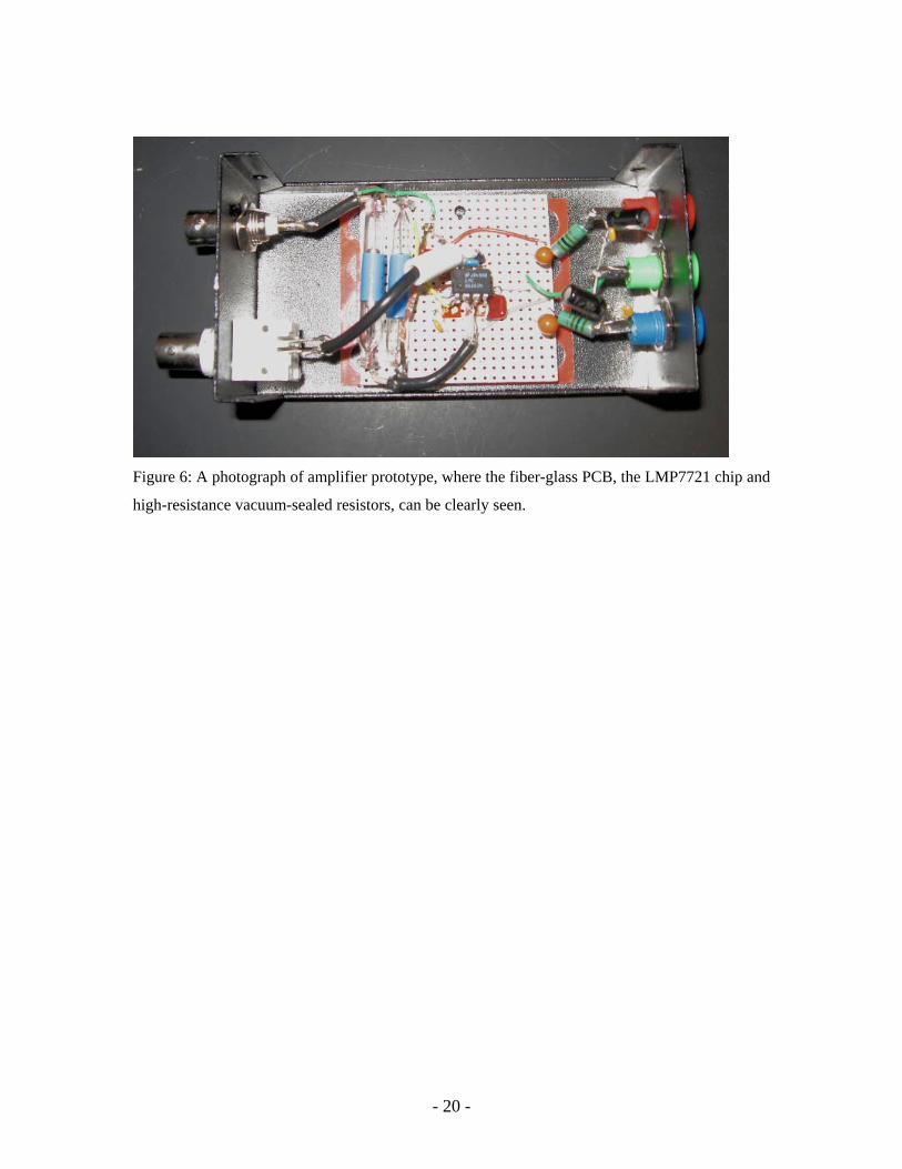
Figure 6: A photograph of amplifier prototype, where the fiber-glass PCB, the LMP7721 chip and
high-resistance vacuum-sealed resistors, can be clearly seen.
- 20 -