A Voice-Based Biometric Watermarking Scheme For Digital ...
177
University of Nevada, Reno A Voice-Based Biometric Watermarking Scheme For Digital Rights Management of 3D Mesh Models A dissertation submitted in partial fulfillment of the requirements for the degree of Doctor of Philosophy in Computer Science and Engineering by Rakhi C. Motwani Dr. Frederick C. Harris, Jr./Dissertation Advisor May, 2010
Transcript of A Voice-Based Biometric Watermarking Scheme For Digital ...

University of Nevada, Reno
A Voice-Based Biometric Watermarking Scheme
For Digital Rights Managementof 3D Mesh Models
A dissertation submitted in partial fulfillment of therequirements for the degree of Doctor of Philosophy in
Computer Science and Engineering
by
Rakhi C. Motwani
Dr. Frederick C. Harris, Jr./Dissertation Advisor
May, 2010

We recommend that the dissertation prepared under our supervision by
RAKHI C. MOTWANI
entitled
A Voice-Based Biometric Watermarking Scheme For
Digital Rights Management Of 3D Mesh Models
be accepted in partial fulfillment of the requirements for the degree of
DOCTOR OF PHILOSOPHY
Dr. Frederick C. Harris, Jr., Advisor
Dr. Sergiu Dascalu, Committee Member
Dr. Konstantinos Bekris, Committee Member
Dr. William Kuechler, Committee Member
Dr. Daulatram Lund, Graduate School Representative
Marsha H. Read, Ph. D., Associate Dean, Graduate School
May, 2010
THE GRADUATE SCHOOL

i
Abstract
Widespread use of 3D artwork has necessitated the need for managing digital
rights of content owners due to illegal peer-to-peer (P2P) distribution of artwork,
which has been one of the major sources of revenue loss for the art industry. Exist-
ing Digital Rights Management (DRM) systems attempt to provide an anti-piracy
framework that restricts the use of content to its rightful user. However, limitations
of technology have consequently led to solution designs that are either very restrictive
(i.e. device-limiting or usage restrictions) or only succeed in discouraging unlawful
distribution by employing tracing mechanisms.
The objective of this dissertation is to contribute towards DRM implementa-
tions to ensure fair rights management such that the needs of both the authors and
consumers are balanced. The proposed biometric-based watermarking scheme allows
DRM systems to enforce copyright protection by imposing individual-limiting usage
rights, thereby eliminating any device dependency or usage restrictions.
The proposed technique embeds the identity of the consumer in the form of a
voice print, into the graphic content. This voice print serves as a watermark and is
created by using a statistical model (Gaussian Mixture Model) representation of the
consumer’s voice sample. Mel-frequency cepstral coefficients, representing feature
vectors of the speaker from the speech signal, are used to generate the statistical
model. Comparison of the embedded watermark with feature vectors extracted from
a newly acquired voice sample from the consumer enable the biometric-based DRM
system to verify the authenticity of the consumer for legitimate access and usage of
the 3D artwork. The scope of this dissertation is limited to 3D mesh models.

ii
Acknowledgments
My sincere thanks go to my advisor, Dr. Frederick C. Harris, Jr. for his endless
support and guidance over the past several years. I am also thankful to my committee
members: Dr. Sergiu Dascalu, Dr. Kostas Bekris, Dr. William Kuechler, and Dr.
Daulatram Lund for their time and feedback on drafts of various publications.
My gratitude goes to my elder brother, Mukesh, who dedicated countless number
of hours in discussion and reading of my work to provide invaluable feedback and
suggestions. I owe special thanks to my parents and friends for their unconditional
love, encouragement and support. I also thank my cat for being patient with not
getting my regular attention and time.
Last but not the least, I am thankful to God for giving me the potential to
complete this work.

iii
Contents
Abstract i
List of Tables iv
List of Figures vii
1 Introduction 11.1 Motivation . . . . . . . . . . . . . . . . . . . . . . . . . . . . . . . . . 11.2 Methodology . . . . . . . . . . . . . . . . . . . . . . . . . . . . . . . 2
1.3 Contributions . . . . . . . . . . . . . . . . . . . . . . . . . . . . . . . 31.4 Dissertation Organization . . . . . . . . . . . . . . . . . . . . . . . . 3
2 Background and Literature Review 4
2.1 Introduction . . . . . . . . . . . . . . . . . . . . . . . . . . . . . . . . 42.2 Digital Rights Management Systems . . . . . . . . . . . . . . . . . . 4
2.2.1 Technology Overview . . . . . . . . . . . . . . . . . . . . . . . 4
2.2.2 Limitations of Existing 3D Multimedia DRM Systems . . . . . 7
2.3 Biometrics . . . . . . . . . . . . . . . . . . . . . . . . . . . . . . . . . 132.3.1 Technology Overview . . . . . . . . . . . . . . . . . . . . . . . 13
2.3.2 Comparison of Various Biometrics . . . . . . . . . . . . . . . . 16
2.4 Digital Watermarking . . . . . . . . . . . . . . . . . . . . . . . . . . . 19
2.4.1 Technology Overview . . . . . . . . . . . . . . . . . . . . . . . 19
2.4.2 Literature Review of Biometric Watermarking of Digital Content 27
2.4.3 Literature Review of 3D Mesh Model Watermarking . . . . . . 31
2.5 Voice Signal Processing . . . . . . . . . . . . . . . . . . . . . . . . . . 39
2.5.1 Speech Production Mechanism . . . . . . . . . . . . . . . . . . 39
2.5.2 Elements of Speaker Verification Systems . . . . . . . . . . . . 44
3 Methodology 51
3.1 Voice Biometric Watermark Generation . . . . . . . . . . . . . . . . . 523.1.1 Digital Speech Acquisition . . . . . . . . . . . . . . . . . . . . 53
3.1.2 Speech Signal Pre-Processing . . . . . . . . . . . . . . . . . . 54
3.1.3 MFCC Feature Extraction . . . . . . . . . . . . . . . . . . . . 563.1.4 GMM Feature Representation . . . . . . . . . . . . . . . . . . 62

iv
3.1.5 Error Correction Encoding . . . . . . . . . . . . . . . . . . . . 69
3.2 3D Mesh Model Watermarking Algorithm . . . . . . . . . . . . . . . 71
3.2.1 Watermark Embedder . . . . . . . . . . . . . . . . . . . . . . 713.2.2 Watermark Detector . . . . . . . . . . . . . . . . . . . . . . . 783.2.3 Error Correction Decoding . . . . . . . . . . . . . . . . . . . . 79
3.2.4 Verification Module . . . . . . . . . . . . . . . . . . . . . . . . 793.3 Proposed Digital Rights Management Model . . . . . . . . . . . . . . 80
3.3.1 DRM System Architecture . . . . . . . . . . . . . . . . . . . . 83
3.3.2 Custom File Format . . . . . . . . . . . . . . . . . . . . . . . 873.3.3 Security Aspects of the DRM System . . . . . . . . . . . . . . 88
4 Software Engineering Design Principles 92
4.1 System Assumptions . . . . . . . . . . . . . . . . . . . . . . . . . . . 92
4.2 Requirements Specification . . . . . . . . . . . . . . . . . . . . . . . . 93
4.2.1 Non-Functional Requirements . . . . . . . . . . . . . . . . . . 93
4.2.2 Functional Requirements . . . . . . . . . . . . . . . . . . . . . 95
4.3 System Design . . . . . . . . . . . . . . . . . . . . . . . . . . . . . . . 96
4.4 Use Cases . . . . . . . . . . . . . . . . . . . . . . . . . . . . . . . . . 984.5 Requirements Traceability Matrix . . . . . . . . . . . . . . . . . . . . 100
4.6 User Interface . . . . . . . . . . . . . . . . . . . . . . . . . . . . . . . 101
5 Experimental Results 109
5.1 Effectiveness of the Watermarking Scheme . . . . . . . . . . . . . . . 109
5.1.1 Perceptibility and Embedding Capacity . . . . . . . . . . . . . 110
5.1.2 Robustness . . . . . . . . . . . . . . . . . . . . . . . . . . . . 1125.2 Parameter Evaluation of Voice Biometric System . . . . . . . . . . . 117
5.3 Overall System Performance . . . . . . . . . . . . . . . . . . . . . . . 124
5.3.1 Interpretation of Results . . . . . . . . . . . . . . . . . . . . . 145
6 Summary and Discussion 146
6.1 Conclusions . . . . . . . . . . . . . . . . . . . . . . . . . . . . . . . . 1466.2 Contributions . . . . . . . . . . . . . . . . . . . . . . . . . . . . . . . 1496.3 Limitations . . . . . . . . . . . . . . . . . . . . . . . . . . . . . . . . 1506.4 Future Work . . . . . . . . . . . . . . . . . . . . . . . . . . . . . . . . 152
Bibliography 155

v
List of Tables
2.1 Performance Evaluation of Commonly Used Biometrics . . . . . . . . 18
2.2 Comparison of Various Watermarking Schemes . . . . . . . . . . . . . 38
3.1 Header Fields of Custom File Format . . . . . . . . . . . . . . . . . . 89
5.1 Comparison Of Original Model With Watermarked Model . . . . . . 110
5.2 Smoothing Attacks . . . . . . . . . . . . . . . . . . . . . . . . . . . . 112
5.3 Noise Attacks . . . . . . . . . . . . . . . . . . . . . . . . . . . . . . . 1135.4 Geometric Attacks . . . . . . . . . . . . . . . . . . . . . . . . . . . . 1145.5 Cropping Attacks . . . . . . . . . . . . . . . . . . . . . . . . . . . . . 117
5.6 Experiments on Voice Print Generation Algorithmic Parameters (N=numberof MFCC Coefficients, M=GMM order) . . . . . . . . . . . . . . . . 123
5.7 Measure of Overall System Performance . . . . . . . . . . . . . . . . 127
5.8 3D Model Nefertiti- Impact of Gaussian Noise on Voice Biometric Wa-termark of Length 127 (m = 7) that Accommodates a Voice print ofSize 75 (GMM order 3) . . . . . . . . . . . . . . . . . . . . . . . . . . 128
5.9 3D Model Robot- Impact of Gaussian Noise on Voice Biometric Water-mark of Length 255 (m = 8) that Accommodates a Voice print of Size125 (GMM order 5) . . . . . . . . . . . . . . . . . . . . . . . . . . . . 129
5.10 3D Model Robot- Impact of Gaussian Noise on Voice Biometric Water-mark of Length 255 (m = 8) that Accommodates a Voice print of Size75 (GMM order 3) . . . . . . . . . . . . . . . . . . . . . . . . . . . . 129
5.11 3D Model Beetle- Impact of Gaussian Noise on Voice Biometric Water-mark of Length 230 that Accommodates a Voiceprint of Size 75 (GMMorder 3) . . . . . . . . . . . . . . . . . . . . . . . . . . . . . . . . . . 130
5.12 3D Model Horse- Impact of Gaussian Noise on Voice Biometric Wa-termark of Length 765 (m =8), Voiceprint size is 225 (GMM order 9,voiceprint is split into 3 equal parts with each part having a codewordof size 255, the 3 codewords concatenate to form the watermark) . . . 130
5.13 3D Model Horse- Impact of Gaussian Noise on Voice Biometric Wa-termark of Length 765 (m =8), Voiceprint size is 75 (GMM order 3,voiceprint is split into 3 equal parts with each part having a codewordof size 255, the 3 codewords concatenate to form the watermark) . . . 131
5.14 3D Model Dinopet- Impact of Gaussian Noise on Voice Biometric Wa-termark of Length 1275 that Accommodates a Voiceprint of Size 375(GMM order 15) . . . . . . . . . . . . . . . . . . . . . . . . . . . . . 131

vi
5.15 3D Model Dinopet- Impact of Gaussian Noise on Voice Biometric Wa-termark of Length 1275 that Accommodates a Voiceprint of Size 75(GMM order 3) that is split into 5 parts with each part forming acodeword of size 255 . . . . . . . . . . . . . . . . . . . . . . . . . . . 132
5.16 3D Model MaxPlanck- Impact of Gaussian Noise on Voice BiometricWatermark of Length 510 that Accommodates a Voiceprint of Size 150(GMM order 6) . . . . . . . . . . . . . . . . . . . . . . . . . . . . . . 132
5.17 3D Model MaxPlanck- Impact of Gaussian Noise on Voice BiometricWatermark of Length 510 that Accommodates a Voiceprint of Size 75(GMM order 3) that is split into 2 parts with each part forming acodeword of size 255 . . . . . . . . . . . . . . . . . . . . . . . . . . . 133
5.18 3D Model Camel- Impact of Gaussian Noise on Voice Biometric Water-mark of Length 765 that Accommodates Voiceprint of Size 255 (GMMorder 3) repeated three times . . . . . . . . . . . . . . . . . . . . . . 133
5.19 3D Model Camel- Impact of Gaussian Noise on Voice Biometric Water-mark of Length 765 that Accommodates Voiceprint of Size 75 (GMMorder 3) split 3 times . . . . . . . . . . . . . . . . . . . . . . . . . . . 134
5.20 3D Model Armadillo- Impact of Gaussian Noise on Voice BiometricWatermark of Length 6630 that Accommodates a Voiceprint of Size255 (GMM order 3) repeated 26 times . . . . . . . . . . . . . . . . . 134
5.21 3D Model Armadillo- Impact of Gaussian Noise on Voice BiometricWatermark of Length 6375 that Accommodates a Voiceprint of Size 75(GMM order 3) split 25 times . . . . . . . . . . . . . . . . . . . . . . 135
5.22 3D Model Nefertiti- Impact of Cropping along X-Axis on Voice Bio-metric Watermark of Length 127 (m = 7) that Accommodates a Voiceprint of Size 75 (GMM order 3) . . . . . . . . . . . . . . . . . . . . . 136
5.23 3D Model Nefertiti- Impact of Cropping along Y-Axis on Voice Bio-metric Watermark of Length 127 (m = 7) that Accommodates a Voiceprint of Size 75 (GMM order 3) . . . . . . . . . . . . . . . . . . . . . 137
5.24 3D Model Nefertiti- Impact of Cropping along Z-Axis on Voice Bio-metric Watermark of Length 127 (m = 7) that Accommodates a Voiceprint of Size 75 (GMM order 3) . . . . . . . . . . . . . . . . . . . . . 137
5.25 3D Model Nefertiti- Impact of Cropping along X,Y and Z-Axes on VoiceBiometric Watermark of Length 127 (m = 7) that Accommodates aVoice print of Size 75 (GMM order 3) . . . . . . . . . . . . . . . . . . 137
5.26 3D Model Robot- Impact of Cropping along X,Y and Z-Axes on VoiceBiometric Watermark of Length 255 (m = 8) that Accommodates aVoice print of Size 75 (GMM order 3) . . . . . . . . . . . . . . . . . . 138
5.27 3D Model Beetle- Impact of Cropping along X,Y and Z-Axes on VoiceBiometric Watermark of Length 230 that Accommodates a Voiceprintof Size 75 (GMM order 3) . . . . . . . . . . . . . . . . . . . . . . . . 138
5.28 3D Model Horse- Impact of Cropping along X,Y and Z-Axes on VoiceBiometric Watermark of Length 765 (m =8), Voiceprint size is 75(GMM order 3, voiceprint is split into 3 equal parts with each parthaving a codeword of size 255, the 3 codewords concatenate to formthe watermark) . . . . . . . . . . . . . . . . . . . . . . . . . . . . . . 138

vii
5.29 3D Model Dinopet- Impact of Cropping along X,Y and Z-Axes on VoiceBiometric Watermark of Length 1275 that Accommodates a Voiceprintof Size 75 (GMM order 3) that is split into 5 parts with each partforming a codeword of size 255 . . . . . . . . . . . . . . . . . . . . . . 139
5.30 3D Model MaxPlanck- Impact of Cropping along X,Y and Z-Axeson Voice Biometric Watermark of Length 510 that Accommodates aVoiceprint of Size 75 (GMM order 3) that is split into 2 parts witheach part forming a codeword of size 255 . . . . . . . . . . . . . . . . 139
5.31 3D Model Camel- Impact of Cropping along X,Y and Z-Axes on VoiceBiometric Watermark of Length 765 that Accommodates Voiceprint ofSize 75 (GMM order 3) split 3 times . . . . . . . . . . . . . . . . . . 139
5.32 3D Model Armadillo- Impact of Cropping along X,Y and Z-Axes onVoice Biometric Watermark of Length 6375 that Accommodates aVoiceprint of Size 75 (GMM order 3) split 25 times . . . . . . . . . . 140
5.33 3D Model Nefertiti- Impact of Smoothing on Voice Biometric Water-mark of Length 127 (m = 7) that Accommodates a Voice print of Size75 (GMM order 3) . . . . . . . . . . . . . . . . . . . . . . . . . . . . 142
5.34 3D Model Robot- Impact of Smoothing on Voice Biometric Watermarkof Length 255 (m = 8) that Accommodates a Voice print of Size 75(GMM order 3) . . . . . . . . . . . . . . . . . . . . . . . . . . . . . . 142
5.35 3D Model Beetle- Impact of Smoothing on Voice Biometric Watermarkof Length 230 that Accommodates a Voice print of Size 75 (GMM order3) . . . . . . . . . . . . . . . . . . . . . . . . . . . . . . . . . . . . . . 142
5.36 3D Model Horse- Impact of Smoothing on Voice Biometric Watermarkof Length 765, Voiceprint size is 75 (GMM order 3), voiceprint is splitinto 3 equal parts with each part having a codeword of size 255, the 3codewords concatenate to form the watermark) . . . . . . . . . . . . 143
5.37 3D Model Dinopet- Impact of Smoothing on Voice Biometric Water-mark of Length 1275 that Accommodates a Voiceprint of Size 75 (GMMorder 3) that is split into 5 parts with each part forming a codewordof size 255 . . . . . . . . . . . . . . . . . . . . . . . . . . . . . . . . . 143
5.38 3D Model MaxPlanck- Impact of Smoothing on Voice Biometric Water-mark of Length 510 that Accommodates a Voiceprint of Size 75 (GMMorder 3) that is split into 2 parts with each part forming a codewordof size 255 . . . . . . . . . . . . . . . . . . . . . . . . . . . . . . . . . 144
5.39 3D Model Camel- Impact of Smoothing on Voice Biometric Watermarkof Length 765 that Accommodates Voiceprint of Size 75 (GMM order3) split 3 times . . . . . . . . . . . . . . . . . . . . . . . . . . . . . . 144
5.40 3D Model Armadillo- Impact of Smoothing on Voice Biometric Wa-termark of Length 6375 that Accommodates a Voiceprint of Size 75(GMM order 3) split 25 times . . . . . . . . . . . . . . . . . . . . . . 144

viii
List of Figures
2.1 DRM System Types . . . . . . . . . . . . . . . . . . . . . . . . . . . 5
2.2 Software-Based DRM System . . . . . . . . . . . . . . . . . . . . . . 6
2.3 Comparison of DRM Systems. Notations used in the table Y: Yes, N:No, Crypto: Cryptography, WM: Watermarking, -: Unable to Comment 13
2.4 Biometric System Components . . . . . . . . . . . . . . . . . . . . . . 14
2.5 Comparisons of Various Biometrics [8, 54] . . . . . . . . . . . . . . . 17
2.6 Generic Watermarking System . . . . . . . . . . . . . . . . . . . . . . 20
2.7 Watermark Embedder . . . . . . . . . . . . . . . . . . . . . . . . . . 232.8 Watermark Detector . . . . . . . . . . . . . . . . . . . . . . . . . . . 242.9 Research Trend - Biometric Watermarking . . . . . . . . . . . . . . . 28
2.10 Mesh Representataion of 3D Model . . . . . . . . . . . . . . . . . . . 31
2.11 The Human Vocal System [105] . . . . . . . . . . . . . . . . . . . . . 40
2.12 Source-Filter Model for Speech Production . . . . . . . . . . . . . . . 42
2.13 Time-domain Representation of Voice Signal . . . . . . . . . . . . . . 43
2.14 Frequency Analysis of Speech Wave . . . . . . . . . . . . . . . . . . . 44
2.15 Spectrograph . . . . . . . . . . . . . . . . . . . . . . . . . . . . . . . 45
2.16 A Generic Speaker Verification System . . . . . . . . . . . . . . . . . 46
3.1 Enrollment . . . . . . . . . . . . . . . . . . . . . . . . . . . . . . . . 513.2 Authentication . . . . . . . . . . . . . . . . . . . . . . . . . . . . . . 523.3 Discretized Speech Signal: 14 seconds duration, utterance “1 2 3 4 5 6
7 8 9 10” . . . . . . . . . . . . . . . . . . . . . . . . . . . . . . . . . . 543.4 Preprocessed Discrete Speech Signal: 3 seconds duration . . . . . . . 55
3.5 MFCC Block Diagram . . . . . . . . . . . . . . . . . . . . . . . . . . 58
3.6 Extracting Frames from Preprocessed Discrete Signal . . . . . . . . . 59
3.7 Frames of the Preprocessed Discrete Signal before Windowing . . . . 59
3.8 Hamming Window . . . . . . . . . . . . . . . . . . . . . . . . . . . . 60
3.9 Frames of the Preprocessed Discrete Signal after Windowing . . . . . 60
3.10 Fourier Spectrum of one Frame of Windowed Preprocessed DiscreteSignal . . . . . . . . . . . . . . . . . . . . . . . . . . . . . . . . . . . 61
3.11 Mel Bank of Filters . . . . . . . . . . . . . . . . . . . . . . . . . . . . 613.12 Log of Mel Spectrum . . . . . . . . . . . . . . . . . . . . . . . . . . . 62
3.13 Cepstrum . . . . . . . . . . . . . . . . . . . . . . . . . . . . . . . . . 63

ix
3.14 First 12 Mel-Frequency Cepstral Coefficients . . . . . . . . . . . . . . 63
3.15 Gaussian Mixture Model with 20 Gaussians for the first MFCC . . . 643.16 Data with normal distribution approximated by a Gaussian . . . . . . 64
3.17 Gaussian distributions with different mean µ and variances σ2 . . . . 64
3.18 Gaussian Mixture Model of Univariate Gaussian distributions to ap-proximate 1-dimensional feature set . . . . . . . . . . . . . . . . . . . 65
3.19 Gaussian Mixture Models with 20 Gaussians for all 12 MFCCs . . . . 693.20 Watermarking Process . . . . . . . . . . . . . . . . . . . . . . . . . . 71
3.21 3D Model of Horse and the Mesh Representation . . . . . . . . . . . 72
3.22 1-Ring Neighborhood(highlighted in red) of Vertices . . . . . . . . . . 73
3.23 Face Normals(in blue) . . . . . . . . . . . . . . . . . . . . . . . . . . 73
3.24 Eigen Normal N derived from 6 Face Normals . . . . . . . . . . . . . 74
3.25 Normals Shifted to Pass Through Vertex v . . . . . . . . . . . . . . . 74
3.26 Curvature Variation in the Horse Model . . . . . . . . . . . . . . . . 753.27 Bin Formation in Original Models . . . . . . . . . . . . . . . . . . . . 76
3.28 Vertices Selected for Watermarking (in red) . . . . . . . . . . . . . . 77
3.29 The Original and Watermarked Model of Horse . . . . . . . . . . . . 78
3.30 Watermark Extraction Process . . . . . . . . . . . . . . . . . . . . . . 793.31 DRM System Block Diagram . . . . . . . . . . . . . . . . . . . . . . 81
3.32 DRM System Components . . . . . . . . . . . . . . . . . . . . . . . . 84
3.33 Content Processing . . . . . . . . . . . . . . . . . . . . . . . . . . . . 85
3.34 Content Consumption . . . . . . . . . . . . . . . . . . . . . . . . . . 86
3.35 Header Fields . . . . . . . . . . . . . . . . . . . . . . . . . . . . . . . 87
4.1 Hardware and Software Requirements . . . . . . . . . . . . . . . . . . 94
4.2 System-Level Layered Architectural Diagram . . . . . . . . . . . . . . 97
4.3 Use Case Diagram . . . . . . . . . . . . . . . . . . . . . . . . . . . . 99
4.4 Requirements Traceability Matrix . . . . . . . . . . . . . . . . . . . . 101
4.5 Main GUI - The left panel provides an interface for user enrollment.The right panel provides an interface for user authentication. . . . . . 102
4.6 Voice Signal Preprocessing - The axis on the upper left corner shows aplot of the voice signal (in red) after silence removal. . . . . . . . . . 102
4.7 MFCC Feature Extraction - The axis on the upper left corner plotsthe 12 MFCC coefficients corresponding to the first frame of the firstvoice sample provided by the user. . . . . . . . . . . . . . . . . . . . 103
4.8 GMM Speaker Model - The axis on the upper left corner plots theGaussian mixture model for the first MFCC coefficients of all theframes from the three voice samples.. . . . . . . . . . . . . . . . . . . 104
4.9 Input 3D Mesh Model - The system prompts the user to provide the3D model that needs to be watermarked. . . . . . . . . . . . . . . . . 105
4.10 DRM Protected 3D Model - The axis on the upper left corner shows aplot of the voice signal used for generating the voice print. The bottomright display area shows the watermarked 3D model. . . . . . . . . . 106
x
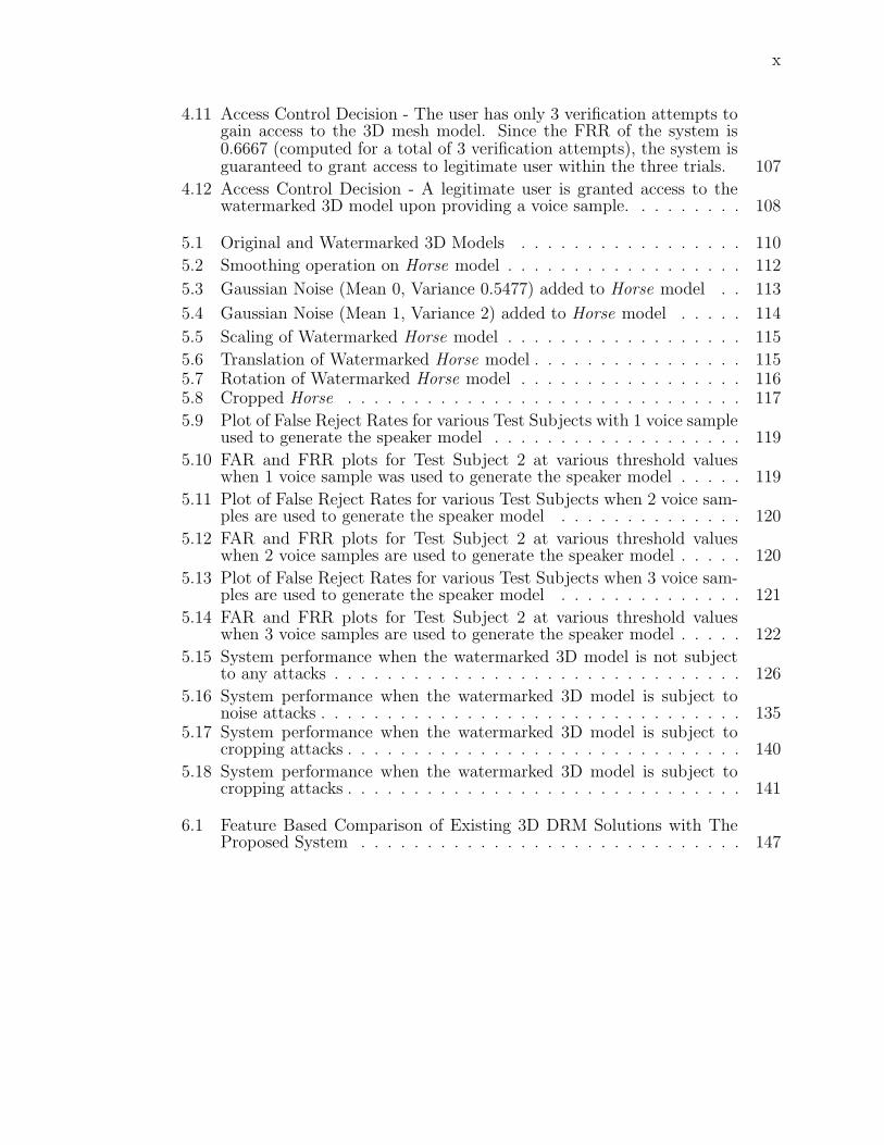
4.11 Access Control Decision - The user has only 3 verification attempts togain access to the 3D mesh model. Since the FRR of the system is0.6667 (computed for a total of 3 verification attempts), the system isguaranteed to grant access to legitimate user within the three trials. 107
4.12 Access Control Decision - A legitimate user is granted access to thewatermarked 3D model upon providing a voice sample. . . . . . . . . 108
5.1 Original and Watermarked 3D Models . . . . . . . . . . . . . . . . . 110
5.2 Smoothing operation on Horse model . . . . . . . . . . . . . . . . . . 112
5.3 Gaussian Noise (Mean 0, Variance 0.5477) added to Horse model . . 113
5.4 Gaussian Noise (Mean 1, Variance 2) added to Horse model . . . . . 114
5.5 Scaling of Watermarked Horse model . . . . . . . . . . . . . . . . . . 115
5.6 Translation of Watermarked Horse model . . . . . . . . . . . . . . . . 1155.7 Rotation of Watermarked Horse model . . . . . . . . . . . . . . . . . 1165.8 Cropped Horse . . . . . . . . . . . . . . . . . . . . . . . . . . . . . . 117
5.9 Plot of False Reject Rates for various Test Subjects with 1 voice sampleused to generate the speaker model . . . . . . . . . . . . . . . . . . . 119
5.10 FAR and FRR plots for Test Subject 2 at various threshold valueswhen 1 voice sample was used to generate the speaker model . . . . . 119
5.11 Plot of False Reject Rates for various Test Subjects when 2 voice sam-ples are used to generate the speaker model . . . . . . . . . . . . . . 120
5.12 FAR and FRR plots for Test Subject 2 at various threshold valueswhen 2 voice samples are used to generate the speaker model . . . . . 120
5.13 Plot of False Reject Rates for various Test Subjects when 3 voice sam-ples are used to generate the speaker model . . . . . . . . . . . . . . 121
5.14 FAR and FRR plots for Test Subject 2 at various threshold valueswhen 3 voice samples are used to generate the speaker model . . . . . 122
5.15 System performance when the watermarked 3D model is not subjectto any attacks . . . . . . . . . . . . . . . . . . . . . . . . . . . . . . . 126
5.16 System performance when the watermarked 3D model is subject tonoise attacks . . . . . . . . . . . . . . . . . . . . . . . . . . . . . . . . 135
5.17 System performance when the watermarked 3D model is subject tocropping attacks . . . . . . . . . . . . . . . . . . . . . . . . . . . . . . 140
5.18 System performance when the watermarked 3D model is subject tocropping attacks . . . . . . . . . . . . . . . . . . . . . . . . . . . . . . 141
6.1 Feature Based Comparison of Existing 3D DRM Solutions with TheProposed System . . . . . . . . . . . . . . . . . . . . . . . . . . . . . 147

1
Chapter 1
Introduction
1.1 Motivation
The past decade has witnessed an explosion of 3D graphics content. Numerous 3D
model catalogs are available online for various industries such as architecture, com-
puter aided design, entertainment, science, medical imaging, archaeological artifacts,
and much more. Such widespread use of 3D artwork has necessitated the need for
managing digital rights of content owners due to illegal peer-to-peer (P2P) distribu-
tion of artwork, which has been one of the major sources of revenue loss for the art
industry. Existing Digital Rights Management (DRM) solutions for 3D multimedia
are either very restrictive (i.e. device-limiting or usage restrictions) or only succeed
in discouraging unlawful distribution by employing tracing mechanisms. While the
objective of DRM is to restrict the use of content to its rightful user, limitations of
technology have consequently led to solution designs that can be broadly classified
into two categories - a) implementations that violate consumer’s rights to fair use(i.e.
using the content without any restrictions) thereby tilting the balance in favor of
the owners, or b) implementations that are ineffective in avoiding unauthorized users
from accessing the content thereby tilting the balance in favor of the consumer. As
a result, DRM systems face the challenge of ensuring fair rights management along
with controlling content access to legal users.
The objective of this dissertation is to contribute towards DRM implementations
such that the needs of both the authors and users are balanced. This research work

2
focuses on addressing the shortcomings and challenges of current DRM schemes, by
proposing to employ a biometric based watermarking solution. Watermarking or in-
formation hiding is an identification technology. Thus far, the most any DRM system
has achieved from utilizing watermarking schemes is a piracy tracing mechanism - by
embedding consumer specific identifiers into the digital content and retrieving these
identifiers from pirated content to determine the consumer responsible for piracy. The
proposed watermarking scheme when used in conjunction with DRM solutions serves
as an access control technology.
1.2 Methodology
The proposed watermarking method embeds a representation of a biometric trait,
which corresponds to the identity of consumer, in the graphic content. Various bio-
metrics such as fingerprint, palm print, iris, retina, hand geometry, face, voice, and
signature are evaluated to select the most feasible biometric trait for the DRM ap-
plication. Upon electing an appropriate biometric characteristic, the next step is
to research feature extraction techniques that measure features, from the biometric
trait sample, which uniquely characterize an individual. Factors such as improper
user interaction with the sensor, temporary alterations of the biometric trait itself
caused by aging and illness, and environmental factors affect the quality and consis-
tency of captured biometric data. To incorporate these intra-user variations, feature
representation techniques have to be incorporated in order to generate a statistical
model of the biometric features. This generated model is then used as a watermark.
Comparison of the embedded watermark with the real-time generated features from
the live capture of the biometric trait from the user allows a DRM system to perform
biometric based authentication for graphic content access and usage.
Use of biometric watermarks enables the DRM system to a) enforce graphic
content access to a legitimate user, b) eliminate the usage-restrictions and device-
limiting drawbacks by imposing human-limiting usage rights, c) track down the
traitor in the distribution chain via the biometric tracer embedded as watermark

3
in the graphic content, and d) prevent large scale online distribution thereby making
piracy substantially harder. However, the underlying assumption for the proposed
scheme is that users are willing to share their biometrics with the graphics distri-
bution agency(considered as a reliable authority) and are unwilling to share their
biometrics on peer-to-peer networks (fearing misuse of personal biometric data by
strangers) to allow illegitimate users to access the copyright protected graphics.
1.3 Contributions
This dissertation contributes to the research community in three directions - i) a novel
biometric watermarking algorithm for 3D mesh models, ii) design of a novel biometric-
watermarking based DRM system, and iii) assessment of the feasibility of integrating
a biometric system with a watermarking system by evaluating the performance of the
overall system and providing directions for future work to develop a commercially
viable system.
1.4 Dissertation Organization
The remainder of this dissertation is structured as follows: Chapter 2 gives relevant
background information on digital rights management systems, biometrics, digital
watermarking, and voice signal processing along with presenting reviewed literature
on 3D multimedia DRM systems, biometric watermarking, and 3D mesh model wa-
termarking techniques. Chapter 3 presents details on the proposed scheme and out-
lines the framework for the proposed biometric watermarking based DRM system.
Chapter 5 presents experiments to evaluate the performance of the proposed method.
Limitations, conclusions, and future research directions are provided in Chapter 6.

4
Chapter 2
Background and Literature Review
2.1 Introduction
This chapter covers the background information for four domains - DRM, biometrics,
3D watermarking, and voice signal processing, and is therefore split into four sections.
Section 2.2 presents the basic architecture of DRM systems along with limitations of
existing DRM solutions for 3D multimedia. Section 2.3 gives relevant background in-
formation on biometrics and outlines characteristics of various biometric traits. Sec-
tion 2.4 provides definitions and background information on watermarking including
a survey of the related literature on - i) biometric watermarking of digital media, and
ii) 3D mesh model watermarking. Section 2.5 discusses fundamentals of voice signal
processing with emphasis on speaker verification techniques and outlines factors that
govern the performance of voice biometric systems.
2.2 Digital Rights Management Systems
2.2.1 Technology Overview
Digital Rights Management (DRM) is a scheme by which content owners use techno-
logical mechanisms to enforce and protect copyrights over the authored digital work.
The objective of a DRM system is to restrict the use of content to its rightful user
in order to facilitate rightful compensation to artists for their work. Depending on
usage scenarios and operating environments, DRM systems architecture [37] and im-

5
plementation vary from vendor to vendor but the basic functionality provided by
each system is equivalent, to facilitate publishing of digital content in a manner such
that the usage of this content can be controlled. Figure 2.1 illustrates the various
DRM systems types along with the respective functionality achieved by the type of
implementation.
Figure 2.1: DRM System Types
A typical DRM solution [88] is implemented through software and involves pro-
prietary formats (file formats and viewers) and generally operates in a client-server
context. The technologies used for digital management of rights include cryptography
and watermarking. Cryptography is used for license management. User rights are
expressed in the licenses which are typically implemented as digital certificates. User
rights specify the number of usages, temporary or partial use, duration of access,
lending rights, and number of devices on which the content can be used. Licenses
generally contain an identifier of a user who has purchased the content, or an identi-
fier of a device on which the license may be used. Watermarking is a data embedding
technology used primarily for tracing purposes. It is used to identify the source of
illegal distribution by analyzing the user-specific identifier embedded in the digital
content prior to its distribution. DRM systems can also be realized in hardware
through integrated circuits [132] and biometric devices [82].
DRM System Architecture
Figure 2.2 portrays the framework of a typical client-server based DRM scheme. The

6
Figure 2.2: Software-Based DRM System
functional components of this system include - i) server-side content management:
responsible for packaging of the digital content by translating the contents into a
proprietary format, ii) server-side license management: expression of usage rights
pertaining to each customer in terms of licenses, iii) server-side content distribution:
responsible for access and tracking management modules that handle the registration
of users, payments, authentication, and obtain statistical information about the use
of the DRM system, and iv) client-side license enforcement and rights management: a
proprietary content consumption application that enforces user-specific access rights
specified in the license.
Security Aspects of a DRM System
The goal of an adversary is to try to break the security of the system in order to
obtain the digital content in an unprotected form. Therefore, it is necessary to build
a security model [64] that states the security goals of the system along with the

7
threat and trust models. The threat model identifies all possible means by which an
adversary can attempt to attack the system. The trust model describes entities that
are trusted not to have vulnerabilities that give rise to a threat. Readers are advised
to refer to [62] or [63] for further details and specifics on how to analyze the security
of a DRM system. Section 3.3 analyzes the security aspects of the proposed DRM
framework.
2.2.2 Limitations of Existing 3D Multimedia DRM Systems
Published literature on 3D graphics DRM is very limited. The issues with existing
DRM systems that are highlighted in the literature can be summarized as:
• Device-limiting access
• Usage restrictions
• Unauthorized access
Related work on digital rights management of 3D graphics is analyzed based on
the type of implementation:
Client-Server Based Implementation
Stanford University has signed a contract with the Italian authorities to protect the
laser scanned high resolution 3D digital sculptures of Michelangelo by making the
artwork available only to established scholars for noncommercial use. The goal of the
team [68] that has undertaken the project is to prevent piracy of the 3D models such
that simulated marble replicas are not manufactured by unauthorized entities. To
achieve this objective, they have implemented a remote-rendering system with client-
server architecture that allows interactive display and manipulation of the artwork
but provides only low resolution 2D renderings to academic users. To address the
analog attack, the authors discourage 3D reconstruction from 2D images by having
the server impose constraints on rendering requests, disallowing extremely close-up
views of models and requiring a fixed field of view. This DRM model is geared

8
towards shared content security and counters piracy by restricting what users can do
with the graphics. The user, however, can share his login credentials but this kind
of dishonesty does not impact the content owner’s primary objective of preventing
piracy. While this system is not device binding and can be accessed from any machine,
it does limit the users’ flexibility to use the graphics as the user does not own the
content. This system is not designed as a business model to trade, manage, and
monitor redistribution of sold content.
PTC [17] deployed a product called Pro/Engineer which customizes Adobes Live-
Cycle Rights Management ES [50] software for copyright protection of 3D CAD files.
The purpose of the product is to restrict access of 3D CAD files (i.e. open, copy,
change access restrictions,) to approved personnel. Implementation of this product
is based on use of web services, authentication systems, and enterprise content man-
agement systems for centralized document protection, control, and administration.
Lightweight Directory Access Protocol (LDAP) and Microsoft Active Directory im-
plementations are used to authenticate recipients’ credentials and provide protection
based on existing identity and group structures. This DRM solution protects the
graphic owner’s right by offering content to consumers in a restrictive usage environ-
ment.
Cryptography-Based Implementation
There is no published work for this category. However, a product OwnerGuard [5] is
available in the market and provides DRM functionalities for 3D AutoCAD drawings
by use of licenses. Licenses define the rules for how the files can be used. License
can be generated by specifying the i) time limitations - license duration or expire
date, ii) input output limitations - allow copy to clipboard, screen capture, OLE drag
and drop, save to new files, write protect the file, and iii) dependencies - hardware
identifier of machine or operating system version.
In addition, Visual Rights is another commercial product rolled out by Informa-
tive Graphics [36] for enterprise document management by providing security controls

9
that can be applied to a given file when published for viewing by one of company’s
products. This product provides copyright protection for documents, images, 2D and
3D CAD files. It is a client-server based implementation that utilizes proprietary file
formats and viewers. The system utilizes standard AES 256 bit encryption. Users
can publish a protected file and add controls such as password protection, hard or
relative viewing expiration dates, allow/disallow printing and copying. For 3D CAD
models, the product disables measurement and viewing with CAD layer controls and
also supports blocking out specific content within a drawing file or hide the interior
details of a model completely.
Cryptography-based digital rights management solutions use keys to protect con-
tents and licenses to define access rights [89]. Content is bound to a license, and the
content is only accessible as per the rules specified in the license. Implementations
vary from vendor to vendor but a typical cryptographic solution locks the graphics
file with a public key and packages the locked content with a header. The header
contains an identifier to the public key and a location to the license associated with
that file. The public key used to lock the file is unique to every user. This packaged
content is encrypted and distributed to the consumer. The license consists of a user
specific identifier that binds the license to the corresponding content, the public key
that unlocks the content, seller’s certificate to decrypt the packaged content and rules
governing the use of the graphic content such as time limitations, counted number
of usages, disabling copying of content, machine dependency, and restricting content
editing. The associated license is encrypted and stored on a license management
server at the seller’s end. To access the purchased protected content, the buyer needs
to get the license from the seller. The content consumption application on the buyer’s
side sends the user specific identifier to query the license server for retrieving the as-
sociated license. The user side application then checks the validity of the license,
interprets and enforces the rules in the license to provide appropriate content access
to the user.
Based on the usage policies defined in the licenses, these systems provide con-

10
tents in limited usage conditions and usage environments. If the license is machine
dependent, containing the hardware ID of the buyer’s computer, it forces the content
to be accessed on one computer. If the license is machine independent, the license
can be illegally shared along with the content on P2P sites. Generally in such cases,
the license server monitors the usage of the file from the license requests and mul-
tiple simultaneous illegitimate access attempts can be detected and denied by the
server. But stand-alone offline systems cannot perform this check and fail to prevent
unauthorized usage, thereby falling short of protecting the rights of content owners.
Cryptography and Watermarking-Based Implementation
Sohn et al. [134] propose a watermarking based 3D data files security component for
an Intelligent Manufacturing System which is used to develop digital prototypes in the
manufacturing industry. The objective of this system is to prevent 3D data files from
leaking out of the organization. This server-based 3D watermarking system, named
3DGuard, works according to security policies that define the user’s access rights and
permissions. A watermarking plug-in intercepts a users upload or download action
in order to embed, retrieve, or remove watermarks on 3D files as per security policies
stored on server. Every 3D data file has a watermark that is specific to the user who
last accessed the file from the system. In case a 3D data file is leaked out of the
organization, the source of the leak can be determined by analyzing the user-specific
watermark embedded into the file.
Kwon et al. [71] present a DRM scheme for 3D animation games serviced in
mobile devices. Due to the limited bandwidth and high cost associated with directly
downloading game content to a mobile device, game sellers allow consumers to down-
load the game on a PC and then transfer the content to a mobile device. The scheme
is designed to prevent illegal redistribution of purchased 3D game content by address-
ing scenarios where consumers illegally transfer the PC downloaded game content to
multiple mobile devices. Authors present a solution that employs the Buyer-Seller
watermarking protocol [85] for consumers protection and tracing illegal redistribu-

11
tion. The consumer generates a pair of public and private keys. The public key is
circulated to a third-party referred to as the Watermarking Certification Authority,
who is responsible for generating an encrypted watermark for the buyer. The water-
mark is then sent to the seller to embed into the game content. The seller inserts a
second watermark in the game as well in case the consumer is able to remove the first
watermark from the game content. The seller encrypts the game content with the
buyer’s public key such that the game can only be unlocked by the buyer using his
private key. This encryption safeguards the consumer from dishonest sellers who may
illegally redistribute a buyer’s game to other consumers and hold the buyer respon-
sible for piracy. Since the buyer is the only one with access to the private key that
decrypts the game content, that game content cannot be unlocked by anyone else.
Should the buyer share his private key and a pirated copy of the game is found, the
seller verifies the unique tracer watermark of each buyer and determines the specified
buyer suspected of unauthorized distribution.
These DRM solutions offer consumers full access to content, but the nature of
the implementations facilitate users to make illegal copies as well. Therefore, these
systems fails to prevent unauthorized distribution and usage. However, these systems
do succeed in deterring illegal circulation since consumers are aware of the possibility
of being tracked down and held responsible for piracy if the pirated content is found by
the owners. The underlying assumption is that the watermark has not been damaged
by the consumer to remove traces of his identity from the pirated graphic content.
However, in order to make sure the tracer watermark identifies a customer without
any disputes, the kind of watermark used should be unique to every customer.
Hardware-Based Implementation
Shi et al. [132] present a hardware-based digital rights management solution that
integrates digital rights functionalities within the Graphics Processing Unit (GPU).
Their goal is to counter piracy of real time graphics entertainment software. Authors
propose the hardware design and API extensions to integrate cryptography within

12
the GPU. The GPU has two additional components - a cryptographic unit to decrypt
graphics data during rendering in real-time, and a license verification unit to process
texture and shader binding constraints designated in the licenses of graphics data to
circumvent security threats posed by loose coupling of textures and shader programs
with geometry data.
Hardware DRM solutions provide a higher level of protection as opposed to soft-
ware DRM solutions as it is difficult to break the system by software based attacks
or by hardware tampering to dump signal traces at chip interconnects. However,
hardware systems are not feasible for the consumer market due to cost concerns [26]
since appropriate hardware components need to be installed on the consumers com-
puter. Besides, this system is realized on a GPU architecture simulator. Hardware
realization of the concept is far from reality yet, as the nature of the presented re-
search requires a cross-disciplinary collaboration in digital rights management (DRM)
community, graphics researchers, and GPU architects.
Comparison of DRM Solutions for 3D Multimedia
An assessment of the existing solutions based on - i) owner requirements or rights, ii)
user requirements or rights, and iii) system features, and the comparison of various
solutions is presented in Figure 2.3.
As far as the owner requirements are concerned, the digital content owner strives
to prevent unauthorized usage to compensate for revenue losses incurred due to piracy.
Should the content be leaked out of the DRM system, the owner prefers to have a
mechanism that facilitates tracing the origin of piracy. Users require a system that
provides content in a restriction free environment with no binding to any one machine.
A DRM system is mainly characterized by three features - the ease with which it can
be circumvented, the technology used for its implementation, and whether the system
is interoperable with other systems or adopts a proprietary solution.
The objective of this dissertation is to integrate biometry, watermarking, and
cryptography with client-server based DRM systems to support attributes of deter-

13
Figure 2.3: Comparison of DRM Systems. Notations used in the table Y: Yes, N: No,Crypto: Cryptography, WM: Watermarking, -: Unable to Comment
ring unauthorized usage, tracing origin of piracy, eliminate system imposed usage
constraints on consumer, device independent use, and interoperability, as outlined in
the last column of the comparison matrix.
2.3 Biometrics
2.3.1 Technology Overview
Definition
Biometrics is defined as the science and technology of measuring and statistically
analyzing biological data of humans for the purpose of identification. The biological
feature may be based on either a physiological characteristic - such as fingerprints,
palm prints, facial features, iris, retina, vein patterns, or a behavioral characteristic -
such as voice, handwritten signature, gait, and keystrokes.
Biometric System Functionality
A biometric system involves two phases - enrollment and authentication. During
enrollment, the system acquires biometric data samples from an individual, extracts

14
relevant features from the data, creates a mathematical representation of the data
and stores it as a template. During authentication, this template is used to compare
features extracted from the newly acquired biometric samples of the user to accept
or reject the user from the system. Figure 2.4 outlines the components of a generic
biometric system.
Figure 2.4: Biometric System Components
• Electronic sensor - for acquisition of the biometric trait in digitized form.
• Pre-processor - to simplify the acquired digital signal for subsequent opera-
tions without losing relevant information (such as eliminate noise or redundant
information, or enhance the signal).
• Feature Extraction - to reduce the size of data by measuring certain features that
correspond to the identity of an individual. A comprehensive literature review
has been presented in [106] for different approaches employed for biometric
feature extraction and template generation.
• Feature Representation - to construct a complex mathematical representation
for features extracted for a particular individual. Multiple samples of a users
biometric trait very rarely yield the same feature set that was derived from the
enrollment sample. This is mainly due to imperfect sensing conditions arising

15
out of faulty sensors, temporary variations in the users biometric characteristic
due to injury/illness, changes in environmental conditions that introduce back-
ground interference in the signal, and improper interaction of the user with the
sensor resulting in incomplete or unusable biometric samples. This variability in
the biometric feature set of an individual is referred to as intra-class variation,
which the constructed statistical model (also known as the biometric template)
attempts to incorporate. For implementation details on various techniques to
generate a biometric template for fingerprint, signature, face, and voice, readers
should refer to [4].
• Template Matcher - used during authentication and constitutes a matching algo-
rithm to compare the biometric features with the stored templates to determine
user legitimacy.
Biometric Characteristics
It must be noted that no biometric measure can identify a person in a large popula-
tion. Biometrics can only link an individual to a biometric pattern. The quantitative
measures derived from a biometric trait can be extensively dissimilar or much alike
across a population of individuals. Therefore, the performance of any biometric sys-
tem is characterized by the following measures:
1. False Rejection Rate (FRR) - the probability that a true user identity claim will
be falsely rejected, thus causing inconvenience to the user.
2. False Acceptance Rate (FAR) - the probability that a false identity claim will
be accepted thus allowing fraud.
3. Equal Error Rate (EER) - the performance of a biometric system can also be
evaluated in terms of this single-valued measure. The plot of FRR against FAR
at various thresholds results in the Detection Error Tradeoff (DET) curve, a
plot of which is shown in Chapter 5. EER is computed from the DET curve
where the FAR equals the FRR.

16
Additional quantitative measures are:
• False Non-Match Rate(FNMR) - the probability that the acquired sample will
not match the enrollment model.
• False Match Rate(FMR) - the probability that the acquired sample will match
the enrollment model of another user.
• Failure To Enroll Rate (FMR) - the probability that a user will not be able to
supply a readable measure to the system upon enrollment.
In our work we treat FAR/FMR and FRR/FNMR synonymously although these
terms are not always equivalent [83]. In order to circumvent a biometric system, a
user needs to create a false match by biometric mimicry or forgery of an enrolled
user’s biometric features. False non-matches arise out of low threshold values. Based
on the nature of the application and the desired level of security to be achieved by the
biometric system, the threshold can be lowered to reduce false accepts or increased
to reduce false rejects.
It must also be noted that biometric measures cannot be revoked if compromised
i.e. stolen or mimicked. Furthermore, privacy and security of biometrics is another
factor of concern while devising a system that incorporates biometric data [1, 57].
2.3.2 Comparison of Various Biometrics
The choice of a biometric trait for a particular application is based on the error rates
and failure rates discussed above, and various other factors discussed below. While
each biometric trait has its pros and cons, this section only provides a brief overview
of these characteristics for the most commonly used biometric traits. Readers are
strongly advised to refer to [52] for an in-depth analysis of each biometric trait.
The most commonly used biometrics [20] for user authentication or personal
identification are fingerprints, iris, hand geometry, face, voice, and signature. These
traits are evaluated on the following factors [8, 54]: i) ease of use - how easy is it for
the user to interact with biometric sensor, ii) user acceptance - a person’s willingness

17
to offer this trait for authentication and determining if the system is easier, faster,
friendlier, and more convenient than the alternatives, iii) distinctiveness - extent to
which the trait shows great variation over the population, iv) circumvention - ease
with which the authentication system can be deceived by use of a substitute, v)
long-term stability - variance of the trait with age, vi) sensor cost - price for the
biometric trait scanning device, vii) template size - memory storage space required
by the digitally compact and unique representation of the biometric trait, and viii)
variability - factors owing to which the trait is inconsistent and varies among samples
taken from the same individual at different instances of time. Figure 2.5 compares
the most commonly used biometrics based on these factors.
Figure 2.5: Comparisons of Various Biometrics [8, 54]
The false match and non-match error rates for the most commonly used biomet-
rics are listed in Table 2.1. These numbers are collected from [53].

18
Table 2.1: Performance Evaluation of Commonly Used BiometricsBiometric FTE FNMR FMRFace N/A 4% 10%Finger 4% 2% 2%Hand 2% 1.5% 1.5%Iris 7% 6% ≤0.001%Voice 1% 15% 3%
Why did we chose Voice Biometric for our Application?
Studies ([57, 101]) on comparison of various physiological biometrics (fingerprint, face,
iris, retina, palm print) and behavioral biometrics (handwritten signature, voice, gait,
keystroke dynamics) indicate iris and fingerprints as the most desirable biometric
traits due to their persistence over time (least variability of biometric trait with age),
performance (lower false accept and false reject rates) and distinctiveness (uniqueness
of the trait in the population) properties. However, these traits are not appropriate
for use in DRM systems owing to user’s unwillingness to offer these traits to non-
government organizations due to privacy concerns. Besides, special and expensive
hardware device such as fingerprint scanners or high resolution iris image capture
cameras would be required to install at the client-side.
Since user acceptance drives the success of any application, we consider signa-
ture, face, and voice biometric traits as the most eligible candidates for selection.
Hand geometry is not appropriate for DRM applications since is not unique for every
individual and requires bulky scanners. In addition to sensor costs for handwrit-
ten signature scanning being relatively higher than face and voice biometric sensors,
signatures can also be easily forged; therefore, this trait is not considered to be favor-
able. Face and voice are more practical choices in this context assuming that desktop
PCs and laptops are equipped with in-built cameras and microphones. However, face
image acquisition requires fixed head pose, fixed background and appropriate illu-
mination conditions. These conditions are not feasible to control at the user’s end.
On the other hand, local acoustics such as no background noise for voice capture,
is relatively easier to impose as a requirement on the user. With face biometrics,

19
the camera can be easily spoofed by a face photograph in place of a live face, while
a voice biometric system can be spoofed by a pre-recorded voice sample of an indi-
vidual. But voice has an added benefit which static biometric traits such as face,
fingerprint and iris lack - owing to its behavioral and dynamic nature this biometric
serves as a dual channel with the capacity of delivering information (spoken words)
along with personal identity (speaker’s voice). This unique feature of voice can be
exploited to deal with spoofing (using user’s pre-recorded speech) and data simulation
attacks [151] on the biometrics authentication process. Prompting the user to speak
random phrases [41] during authentication introduces an additional layer of verifica-
tion (since the user’s pre-recorded speech can no longer bypass the authentication
process) and increases the overall security of the system.
Therefore, factors such as higher security, cost-effectiveness of biometric sensor
device (affordable low cost PC microphone device), ease of voice acquisition with less
restrictions on the user for capturing the biometric trait, pervasiveness (automated
speech recognition telephone systems), and less complexity in signal processing due
to voice’s one-dimensional nature, make voice a good candidate for selection as a
biometric trait for watermarking.
2.4 Digital Watermarking
2.4.1 Technology Overview
Terminology
Digital watermarking is defined as perceptible or imperceptible insertion of informa-
tion into digital content for the purpose of copyright protection, owner identification,
content authentication, tamper detection, data labeling, access control, or various
other applications [18].
The digital host medium in which the copyright information is embedded is referred
to as the cover or host signal. The different watermarking host media are - digital

20
documents, digital images, audio, video, 3D models, graphic animations, executable
code, and integrated circuits.
The embedded information that is inserted in the cover-signal, is referred to as the
payload or watermark. The digital watermark encoded into digital data is an identify-
ing code and may consist of a bit sequence, random numbers, text representing user’s
unique ID or copyright ownership message or cryptographic keys or access conditions
of the content, logos, image, biometrics or content-based information.
The watermarking scheme is defined as the set of algorithms required for insertion
and extraction of the watermark. Figure 2.6 shows the two components of a water-
marking system - embedder and detector. The embedder is responsible for inserting
the watermark into the digital content, while the detector is responsible for retrieving
this embedded watermark from the host medium.
Figure 2.6: Generic Watermarking System
Desired Properties of a Watermark
Watermarking schemes are evaluated on the basis of these two measures:
• Unobtrusiveness - The embedded watermark should not interfere with intended
use or function of the host data. Perceptible watermarks are therefore faded to
appear in the background as transparent marks or are placed in the bottom or
top corner of the visual media to serve as proof of ownership and to imply au-
thenticity of the content. On the other hand, imperceptible watermarks should

21
be embedded in a way that does not distort the original media by creating any
visual artifacts.
• Robustness - Robustness requirement is necessary to assure that common signal
processing and malicious modifications do not impact the detection or retrieval
of the watermark. Any attempts to delete the watermark should destroy the
watermark itself or damage the host data or else the watermark should resist
all attacks. The embedded watermark should persist despite geometric trans-
formations and noisy transmission channels. The objective of this requirement
is to facilitate content owners to prove their ownership over illegitimate copies
of their media by retrieving the watermark from a pirated medium and then
litigate against the offender.
Watermarking Research Areas
The four principal components of digital watermarking schemes which distinguish
one watermarking algorithm from another are - i) what information is inserted as a
watermark, ii) where is the watermark inserted into the host media, ii) how is the
watermark inserted into the data of the host medium (i.e. addition, subtraction,
bitwise operation), and iv) what is the payload size i.e. how many information bits
can be embedded as watermark. Components ii)-iv) also constitute as the major
areas of research in the watermarking field, with the focus on achieving high payload
capacity while maintaining imperceptibility of the embedded watermark.
Classification of Watermarking Schemes
The category of a watermarking scheme is determined by one of the following prop-
erties:
1. Perceptibility
The application scenario of a particular digital content determines whether a
watermark should be perceptible or imperceptible. A perceptible watermark is
most commonly used for ownership identification and informing users that the

22
content is authentic. However, such watermarks are easy to remove by adver-
saries since the location of the watermark is known (eg. CNN’s logo displayed
at the corner of the broadcasted video content), can be aesthetically ugly at
times, may cover a portion of the content, and their obtrusiveness increases
susceptibility to being cropped. On the other hand imperceptible watermarks
are used for proof of ownership, content labeling, and in validation of intended
recipient. These watermarks are difficult to remove as their location in the host
medium is not known and can only be guessed by an adversary. This distinction
gives rise to two types of watermarking schemes:
i) Visible watermarking, which refers to the process by which the watermark
embedded into the digital content is visible. This watermark is some text or a
logo which identifies the owner of the host media.
ii) Invisible watermarking, which refers to the process by which the watermark
information is added to the multimedia content, such that it cannot be per-
ceived. A watermark can be imperceptibly inserted into a digital host medium
by slightly modifying the host signal.
2. Robustness
This property defines the strength and persistence of the watermark to adver-
sary attacks. The three categories of robustness are listed below:
i) Robust - The watermark can resist modify and/or delete attacks. It can sur-
vive common signal processing operations (such as filtering, compression, noise),
printing and scanning, and geometric distortions (such as rotation, translation,
scaling).
ii) Fragile - The watermark is invalidated by slightest modification of host
medium. It does not survive high noise level, compression, or signal processing
attacks.
iii) Semi-Fragile - The watermark is only destroyed by major changes to the
host medium but survives mild signal processing operations.

23
3. Embedding Method
Figure 2.7 outlines the embedding component of the watermarking system. Ev-
ery host medium has different categories into which the embedding processes can
be classified. For example: image, audio, and video watermarking techniques
modify the host medium in the spatial/temporal domain or the frequency do-
main or in both domains. For 3D graphics the watermark embedding process
can be categorized as geometrical, topological, or vertex re-ordering approaches.
Therefore, the type of method used for inserting the watermark serves as an
important property for classification of watermarking schemes.
Figure 2.7: Watermark Embedder
4. Retrieval Method
Figure 2.8 outlines the three types of extraction or detection process of the
watermark. The watermark detection/extraction process can be informed/non-
blind (retrieval process requires access to the original content (i.e host signal)
along with the embedded piece of data), semi-blind (detector requires access to
some side information and/or the watermark but not the original content), or
blind (detection is performed without access to the original content). In semi-
blind watermarking, the embedding and retrieval process is assisted by a secret
key, in which lies information on where and to what extent has the original
content been modified in order to accommodate the watermark.

24
Figure 2.8: Watermark Detector
Attacks
This section lists the most common category of attacks on a watermarking system.
Further reading [18, 69] is required for those interested in gaining more insight into
different categories of attacks.
• Signal Processing Operations - The adversary subjects the watermarked con-
tent to various operations such as filtering, dithering, cropping, scaling, and
compression with the intent to destroy the watermark.
• Geometric Operations- If the watermarked digital content survives affine trans-
formations, the watermarking scheme is resistant to geometric attacks.
• Removal Attack - In this attack, the adversary attempts to remove or destroy
the watermark, without affecting the host medium.
• Forgery Attack- If the attacker is successful in embedding a valid watermark,
then he can claim ownership over the digital content in addition to the true
owner, for there is no legal framework or centralized repository for watermarked
content that can assist in disputing such false claims.

25
• Collusion Attack- In this attack, the attacker uses several copies of the water-
marked content to construct a copy with no watermark.
• Cryptographic Attacks - The adversary attempts to crack security methods
in the watermarking scheme, implements a brute force search for embedded
information, and embeds misleading watermarks.
• Protocol Attacks - The adversary subtracts his watermark from the data to
claim ownership, thereby falsely accusing the true owner of forgery.
To date, no benchmarking tools exist to evaluate the performance of 3D water-
marking algorithms. This dissertation attempts to devise a scheme that can cover
only a subset of the above mentioned attacks, such that the effect of most common
operations on 3D models i.e. noise, cropping, smoothing, and quantization are ana-
lyzed.
Limitations of Watermarking Technology
It is evident from the attacks, that watermarking technology only serves as a deterrent
against wrong-doing. It requires a central repository of the original or watermarked
work and a proper legal framework to be effective. In addition, the lack of any
algorithm being robust to all types of attacks and the lack of a general benchmarking
tool for all types of host media (since each host medium has its own set of properties
that cannot be generalized to be applicable for another medium), has prevented this
technology from penetrating into the industry at a full-fledged scale.
Applications of Watermarking
Watermarks have been used for a wide a variety of applications:
• Authentication - The watermark consists of information that assists in deter-
mining that the content is authentic. If the watermark can be extracted and
matched to the information representing authenticity of the content then it
serves the purpose of content authentication assuring the user that the content

26
has not been altered during its passage through a noisy or non-secure commu-
nication channel.
• Copyrights - The watermark contains information about the rules of usage and
copying which the content owner wishes to enforce. The content consumption
applications or devices that can play the content might look for the watermark
and compare it with information, such as whether the content is on a recordable
storage device, to identify illegal copies and deny to play the content.
• Signatures - The watermark identifies the owner of the content, and is basically
used to help settle ownership disputes.
• Broadcast or Transaction Monitoring - The content consumption applications
embed transaction identifiers as watermarks into the content, which serve as
transaction logs that are detected by automated systems to monitor television
and radio broadcasts, computer networks, and any other distribution channels
to keep track of when, how and where the content appears or is being used.
• Fingerprinting - For security applications, where the same content is distributed
to multiple users, the content is embedded with different watermarks where each
watermark is specific to a user. In case the watermarked content is leaked out
to unauthorized personnel, the content is examined for the unique watermark
to determine the source of leak.
• Data Labeling - The content is labeled by different data using watermarks to
inform the content consumption application of the different purpose or modes
of usage for the same content.
Watermarking in the Industry
Despite its limitations, watermarking technology has been adopted by the industry
for a wide variety of copyright protection applications. What follows is a list of key

27
industry players in multimedia watermarking: Cinea (Video watermarking) [48], Digi-
marc (Document watermarking) [47], GCS Research (Satellite Images watermarking)
[139], MSInternational (Audio watermarking) [16], Philips Electronics (watermark-
ing of Movies) [33], Signum (Documents and Images watermarking) [140], Civolu-
tion (Audion and Video watermarking) [13], Teletrax (Broadcast Monitoring) [141],
Thomson (watermarking of Motion Pictures) [136], Verance (Audio watermarking)
[146], Verimatrix (Video watermarking) [147], Alpha Tec and Houdini (3D Graphics
watermarking) [49, 81].
Since this dissertation deals with biometric watermarking of 3D models, the
next two sections provide an extensive review of biometric watermarking and 3D
watermarking approaches.
2.4.2 Literature Review of Biometric Watermarking of Dig-ital Content
Biometric watermarking embeds a biometric template into the host medium. While
watermarking of multimedia such as image, audio and video is reaching maturity,
watermarking of 3D multimedia is still a technology in its infancy phase. Moreover,
biometric watermarks have not been explored yet for protecting 3D models. Finger-
print, iris, face, voice features, and signature images have been employed by several
biometric watermarking techniques for still images, audio and video. Figure 2.9 shows
the various biometric traits that have been explored for use in digital media.
Due to the lack of any published work on biometric watermarking of 3D multi-
media, this section is a comprehensive review of biometric watermarking literature
for digital documents, images, audio, and video host mediums from the perspective
of what benefits does utilizing biometrics as watermarks offer.
Jain et al. [55] present a fingerprint image watermarking method that embeds
facial information into host fingerprint images. This scheme has the advantage that
in addition to fingerprint matching, the recovered face during the decoding can be
used to establish the authenticity of the fingerprint and the user. Satonaka ([128]

28
Figure 2.9: Research Trend - Biometric Watermarking
and [129]) embeds a face print as a biometric template into face images for biometric
authentication through a distributed network. Biometric watermarking is used for
accurate facial signature authentication. Uludag et al. [56] hide fingerprint minutiae
data in a host image to enable secure exchange of fingerprints. If the host is a face
image, the proposed method provides an additional cue in authenticating the user.
The host image serves as a carrier of the biometric data used for user authentication.
In [54], the authors use eigen-face coefficients to watermark fingerprint images for
security and integrity of fingerprint biometric data. Namboodiri and Jain [103] pro-
pose to secure document images by an image watermark generated from the author’s
digitized handwritten signature. Vatsa et al. [145] propose a biometric image water-
marking algorithm to improve recognition accuracy of face and fingerprint biometric
images in addition to protecting these images from tampering. Sun et al. [137] present
a multimodal biometric scheme using watermarking technique to provide more secure
and reliable personal recognition. Knuckleprint biometric feature is used as water-
mark to be hidden in the palmprint host image. The knuckleprint watermark not only
protects palmprint biometric data, but is also used as a covert recognition. In ad-
dition, the bimodal biometrics recognition provides an improvement in the accuracy
performance of the biometric identification system.

29
Hsieh et al. [45] discuss a copyright protection scheme for images using finger-
print images. The scheme does not alter the host image but encodes a share image
by using features from the host image and scrambled version of the binary fingerprint
image. During the fingerprint retrieval phase this share image is used along with
features extracted from the suspected image to decode the scrambled fingerprint im-
age. Unscrambling rearranges the fingerprint image, which is used to verify copyright.
Hassanien [40] propose to protect the ownership by hiding an iris data into digital
image for an authentication purpose. The idea is to secretly embed iris print in the
content of the image for the purpose of identifying the owner.
In [46], the authors employ multimodal biometric to improve security and pri-
vacy in fingerprint authentication system. The proposed scheme embeds and extracts
an iris template in a fingerprint image. Noore et al. [104] discuss a digital water-
marking technique that uses face image and demographic text data image as multiple
watermarks for protecting the evidentiary integrity of fingerprint images. Jung et
al. [65] present a method that identifies users in compressed video streaming with
their biometric watermark. The proposed algorithm generates watermark using the
preprocessed fingerprint image, and then inserts the image in H.264-based video cod-
ing streams.
Park et al. [108] proposed an iris feature watermarking method on face image
data for the following objectives - multimodal biometric authentication to increase
the authentication accuracy, ownership verification by extracting the embedded iris
print, and transmission of biometric data over non-secure and noisy communication
channel by embedding it as a watermark into host data. Feng and Lin [27] adopt
iris biometric to be inserted as watermark into host document images in order to
protect the document and assist in owner identification. Varbanov and Blagoev [143]
use an MD5 hash of iris templates to watermark digital images. Low et al. [80]
use an offline handwritten signature as watermark for host images to authenticate
the claimed source of the digital image. Claus et al. [148] embed a handwriting
biometric trait as a watermark in the form of signatures, passphrases, and sketches

30
for the purpose of user authentication, ownership identification and verification of
digital content.
Wang et al. [149] describe an authentication scheme of a DRM system which
integrates a watermarking technique and a multimodal biometric system to provide
more secure and reliable personal recognition. In the watermarking algorithm, a face
image is chosen to be the host image and the iris feature is selected to use as a water-
mark hidden in the host image. Hoang et al. [42] adopt biometric watermarking for
security of the biometric templates in user authentication systems. Encryption does
not provide security once the biometric templates are decrypted; therefore, biometric
watermarks are embedded into the decrypted host biometric templates to provide
security after decryption. Teoh et al. [79] insert a handwritten signature in the host
image to establish legitimate ownership.
Paik et al. [66] present a user identification method for H.264 video streams using
a fingerprint watermark. The biometric watermark is used to reduce the potential
danger of forgery or alteration of the host data and to improve reliability of verifica-
tion using automated fingerprint identification systems. Sharma et al. [43] propose a
remote multimodal biometric authentication framework based on fragile watermark-
ing for transferring multi-biometrics over networks to server for authentication. A
facial image is used as a container to embed other numeric biometrics features. The
purpose of the framework is to enhance security and reduce bandwidth. Tee et al. [78]
embed a handwritten signature in the host image as a notice of legitimate ownership.
Rao et al. [117] embed fingerprint biometric features of the owner as a watermark
to prove ownership of digital images. Musgrave’s [100] patent on a generic biometric
watermark system generates a biometrically encoded bitstream from biometric data of
a user and from electronic data to be transmitted to the user. The encoded bitstream
has the biometric data acting as a biometric watermark. The encoded bitstream is
then sent to a decoder of the user, with the biometric watermark providing security
in the transmission.
Lastly, Vatsa et al. [144] discuss a watermarking algorithm that fuses voice fea-

31
tures into a face biometric image. The technique embeds mel-frequency cepstrum
coefficients (MFCC) of an individual’s voice into the face image of the same indi-
vidual. However, the watermark formulation ignores the intra-individual variability
of the voice data and assumes that the MFCC extracted features are invariant for
an individual. A statistical modeling component is required to incorporate variabil-
ity in an individual’s voice features due to factors such as improper interaction with
the biometric sensor, background noise during voice capture, and variations in an
individual’s voice captured at different instances of time. The proposed approach in
this dissertation overcomes these shortcomings in the voice print based watermark
formulation by statistically modeling the voice feature data.
2.4.3 Literature Review of 3D Mesh Model Watermarking
This section presents related work on 3D watermarking with emphasis on mesh mod-
els. Mesh models approximate a 3D object by a set of planar triangles. Due to their
simplicity in representation and speedier rendering mesh models are widely used in
the industry.
Figure 2.10 shows the mesh representation (right) of a 3D model (left). The dots
in the mesh representation represent vertices that define the (x, y, z) co-ordinates
of the mesh model. Other 3D model representations use surfaces that interpolate
parametric curves such as NURBS, B-Splines, and Beizer curves. However, the focus
of this dissertation is to watermark 3D models that are represented by triangular
meshes.
Figure 2.10: Mesh Representataion of 3D Model

32
Mesh models consist of the 3D model’s geometry (a set of (x, y, z) vertices),
and connectivity (triangular faces formed by connecting line segments joining three
vertices). The watermark can be inserted in the spatial domain by modifying the
geometry or connectivity of the mesh model or in the spectral domain by modifying
the spectral coefficients of the mesh model [150]. Extraction of the watermark can
be blind, semi-blind, or informed(non-blind). A non-blind retrieval process requires
access to the original model while semi-blind process requires access to some side
information and/or the watermark but not the original model, and blind retrieval is
performed without access to the original model or the watermark.
There are 3 main approaches to 3D watermarking: 1) geometry-based techniques,
which involve altering the positions of vertices, 2) topology-based techniques, which
modify vertex connectivity, and 3) vertex re-ordering techniques, which change the
order of vertices in the 3D model’s file format representation. An extensive survey
of 3D watermarking algorithms based on these three approaches can be found in
[60]. In addition, readers are also advised to refer to [2] for a thorough survey with
classification and critical analysis of watermarking algorithms for 3D models.
The watermarking approach in this dissertation adopts a geometry based tech-
nique and exploits the curvature variation in meshes using surface normals to embed
the watermark. Curvature estimation is an important task in 3D object descrip-
tion and recognition because surface curvature provides a description of local surface
shape. A variety of curvature computing methods are discussed in [30]. Normal
vectors are most widely used for curvature estimation. The presented related work
focuses on algorithms that embed an imperceptible watermark into a 3D mesh model
by exploiting the normal vector distribution. The related literature is presented by
summarizing the watermarking approach and the robustness of the watermark to at-
tacks such as mesh simplification, remeshing, rotation, scaling, translation, cropping,
noise, and smoothing operations.
Han et al. [38] propose a geometry-based watermarking approach that embeds
a content-based watermark and uses a non-blind detection technique. The authors

33
analyze the mean curvature and fluctuation of curvature of the regions of the 3D
mesh model to choose the appropriate regions to embed the watermark. The Voronoi
method [87] is employed to compute the curvature of the mesh. Fluctuation of curva-
ture is computed from the Gaussian-weighted average of the mean curvature. Regions
with large curvature and low curvature fluctuation are selected to accommodate the
watermark as these causing least visual distortion to the model. A threshold value for
the curvature fluctuation eliminates regions not suitable for watermark insertion. The
watermark is embedded by altering the vertex co-ordinate using a visual distortion
measure and a normalized vertex normal. The technique is robust against rotation,
scaling, cropping, noise, and smoothing.
Kwon et al. [70] propose watermarking for 3D polygonal meshes using normal
vector distribution and extended Gaussian image (EGI) [44]. The 3D model is divided
into patches and the normal vectors of each mesh in the patch are mapped to one of
the several bins that subdivide the unit sphere of the EGI. The length of each bin is
the sum of area for all the meshes that are mapped into it. These bins are arranged
in descending order of their length. Bins with large length are selected as locations
for watermark embedding. The watermark is a 1 bit (0 or 1) random sequence of
length N and the ith bit is embedded in the ith bin corresponding to each patch.
The watermark is embedded by changing the average value of the angle between
the normal vectors of mesh surface and the normal vector of the bin center. The
normal vectors in the selected bin are changed according to the bit of the watermark,
thereby changing the position of vertices in the 3D model. The watermark extraction
process does not require the original model. The algorithm is robust against mesh
connectivity altering, additive noise, and cropping attacks.
Jabra and Zagrouba [51] present a robust watermarking algorithm that exploits
the benefits of geometric, topologic, and spectral schemes to achieve robustness
against a wide variety of attacks. The authors segment the original model into multi-
ple sub-connected meshes that are classified into convex, concave, and plane regions.
The watermarking scheme for each segment is determined by the Gaussian and mean

34
curvature value of these regions. The Gaussian and mean curvatures of convex regions
are positive. Concave regions have a negative mean curvature and a positive Gaussian
curvature while plane regions have Gaussian curvature approximately equal to zero.
A geometric watermarking approach is utilized for concave regions and convex regions
are watermarked using topologic techniques. Spectral watermarking is adopted for
the plane regions where insertion is done in low frequencies. The algorithm employs
a blind detection approach. The algorithm is robust against affine transformations,
mesh simplification, smoothing, remeshing, additive noise, and cropping attacks.
Lee and Kwon [73] propose 3D mesh watermarking using the complex extended
Gaussian image (CEGI) distribution. The meshes in a 3D mesh model are clustered
into various patches using a distance measure. The surface normal vector of each
mesh in a patch is mapped into a unit Gaussian sphere. The weight of each point
in the Gaussian sphere is equal to the area of the mesh surfaces for a given normal.
The weight mapping represents a histogram that records the variation of the surface
area according to the surface orientation. The CEGI concept extends the EGI rep-
resentation by adding the normal distance of a mesh to the origin of the model as
a phase component of the complex weight. Unlike EGI representation, CEGI allows
the pose of the 3D mesh to be extracted and also distinguishes a convex model from a
non-convex model. The watermark bits (0 or 1) are embedded into the normal vector
direction of the meshes that are mapped into cells with large complex weights in the
patch CEGIs. The semi-blind watermark extraction is based on two watermark keys,
the known center point of each patch and a weight rank table of the cells in each
patch. The algorithm is robust against mesh simplification, cropping, and rotation
and does not require the original model for extracting the watermark.
Liu and Yang [76] propose a 3D watermarking scheme based on feature points
that carry the principal shape information of the model. The selected feature points
represent the high variation areas of the model and are used as centroids for a Voronoi
diagram to cluster all the vertices of the model into several segments. For each seg-
ment, the vertices are projected onto a reference plane. The normalized distance

35
between a reference point on the plane and the intersection point of a ray from this
reference point to the surface of the model is used to obtain a range image. A DCT
transform is applied to the range image to embed the watermark (bit -1 or 1). The
watermarked 3D mesh is reconstructed from the modified range data. The detection
of the watermark information requires the original range image. The algorithm is re-
sistant against mesh simplification, additive noise, and cropping. The feature points
in this algorithm are used by mesh simplification and surface subdivision techniques
and maintain the main shape of the mess. If the 3D mesh is attacked by simplifica-
tion, its feature points are survivors. Therefore, this algorithm is resistant to mesh
simplification.
Alface and Macq [3] discuss a 3D mesh watermarking technique based on feature
points. The points for which the minimum and maximum curvatures are equal at a
vertex are referred to as umbilical points. These points share the same curvature in
all directions of the tangent plane. Since umbilical points may be due to noise in the
geometry or due to the coarseness of the sampling of the input mesh, a multi-scale
analysis is adopted to discriminate intrinsic umbilical points from those due to noise.
The scale is the size of the vertex neighborhood used to estimate the curvature at a
vertex. Umbilics representing the larger mean curvature are selected as feature points.
The mesh shape is then partitioned using a geodesic Delaunay triangulation of the
detected feature points. To tackle remeshing manipulations, each of these geodesic
triangle patches is then parameterized and remeshed by a subdivision strategy. These
steps provide a mesh which only depends on the mesh shape and resists to connectivity
or sampling changes. These remeshed patches are then watermarked in the spectral
domain. The algorithm resists affine transforms, white noise addition, smoothing,
cropping, and sampling changes such as decimation, subdivision, or remeshing. The
watermark is retrieved by blind detection.
Motwani et. al [90] propose a wavelet-based watermarking technique that uses
fuzzy logic to determine an optimal value for the watermark amplitude to be inserted
in a 3D model. The system is adaptive to the local geometry of the mesh and inserts

36
an 8-bit grey scale image as a watermark. Initially, all mesh vertices are normalized
and then a wavelet transform is applied by using even vertices to compute scalar
coefficients and odd vertices to compute wavelet coefficients. Fuzzy input variables
are computed considering the geometry of the model such as area, curvature, and
bumpiness of the surface corresponding for each vertex. Curvature and area for
the mesh vertices are computed in the spatial domain whereas bumpiness for the
corresponding vertex is computed in the wavelet domain. Curvature is the amount
by which a geometric object deviates from being flat. Curved surface consist of more
number of smaller triangles as compared to a flat surface. Curvature is computed
by taking average of the angles between surface normals of 6 neighboring vertices
and the average surface normal. Area of the triangular face formed by 3 vertices is
computed by the magnitude of the normal to the triangular patch. A bumpy surface is
a surface which is not smooth but is irregular and uneven. A bumpy surface has more
details associated with it and thus has more watermark holding capacity. Bumpiness
is calculated by dividing the wavelet coefficient magnitude by the length of vector
joining two even neighbors. The output of the fuzzy system is a single value which
corresponds to a perceptual threshold for each corresponding wavelet coefficient. The
watermark is inserted by modifying the magnitude of the wavelet coefficient vector
based on its fuzzy inference value. An inverse 3D wavelet transform is then computed
to get the watermarked model. The algorithm is non-blind and requires the original
model and original watermark to extract the watermark. The algorithm is robust
against smoothing, cropping, affine operations, and noise attacks.
Benedens [7] proposes a geometry-based 3D mesh watermarking scheme that is
resistant to mesh simplification attacks. The system uses a collection of surfaces from
the 3D mesh model as an embedding primitive. These collections are generated by
grouping mesh normals to distinct sets called bins. Each bin is defined by a bin center,
a normal in three dimensional space and a radius, and an angular difference to the
center normal. A bin is assigned all model face normals whose angular difference is
less or equal than the bins radius. Bin centers and radii are chosen in a way so bins do

37
not overlap. The embedding process takes the original model, a key, and a watermark
bit string. From the key, non-overlapping bins, bin centers, and radii, are derived.
For encoding one bit of watermark information, the normals in one bin are changed
with respect to certain measures called feature types, such as the mean normal of
the bin, the mean angle difference of the bin normals to the bin center, and the
amount of normals contained in the kernel of the bin relative to the total amount of
normals in bin. The embedding algorithm tries to move normals towards or away from
the kernel (depending on the bit to be coded) and optimizes the embedding process
with the assistance of a cost measure. The outputs of the embedding process are
the watermarked model and the original feature values which are needed as reference
values in the retrieval process. The semi-blind retrieval process takes the watermarked
model, the key, and the feature values.
Lavoue [72] introduces the notion of roughness for a 3D mesh object. The author
talks about three principal relevant categories of regions in a 3D object, such as edge,
rough, and smooth regions. These categories are associated with different watermark
embedding strengths. A rough region exhibits a high degree of watermark insertion
capacity, whereas a geometric change on edge or smooth regions is much more visible.
For each vertex, the corresponding roughness is processed by computing an asymmet-
ric difference between local average curvatures [14] computed on the original mesh
and on a smoothed version. The average curvatures computed over local windows aim
at detecting regions associated with high geometric variations. These variations can
be due to rough textured regions or edges. On the smoothed version of the object, the
geometric variations disappear while edges are preserved. By computing curvature
difference between original and smoothed versions, the real geometric variations (i.e.
the roughness) are accurately differentiated from the edges. This curvature difference
represents the robust roughness measure for the polygonal meshes and can be used
for selecting appropriate regions for watermarking.
Table 2.2 provides a comparison of the reviewed literature. The majority of the
algorithms reviewed thus far can embed bit sequences only and cannot be adopted for

38
Table 2.2: Comparison of Various Watermarking SchemesAlgorithm Watermark Approach Retrieval RobustnessHan et. al Content Geometry Informed Rotation,[38] -Based Scaling,
Translation,Cropping,Noise,Smoothing
Kwon et. al 1-Bit Geometry Blind Mesh[70] Sequence Simplification,
Cropping,Noise
Jabra and Zagrouba 1-Bit Geometry, Blind Mesh[51] Sequence Topology, Simplification,
Spectral Remeshing,Rotation,Scaling,Translation,Cropping,Noise,Smoothing
Lee and Kwon 1-Bit Geometry Semi- Mesh[73] Sequence Blind Simplification,
Remeshing,Rotation,Translation,Cropping,Noise
Liu and Yang Bit Geometry Semi- Mesh[76] Sequence Blind Simplification,
Cropping,Noise
Alface and Macq 64-Bit Spectral Blind Subdivision,[3] Signature Decimation,
Cropping,Noise,Smoothing
Motwani et. al 8-Bit Spectral Non-Blind Rotation,[90] Grey Scale Scaling,
Image Translation,Cropping,Noise,Smoothing
Benedens et. al Bit Geometry Semi- Mesh[7] Sequence Blind Simplification

39
our approach as we need to embed a biometric template of size over 2 KB for a voice
signal. The proposed watermarking algorithm computes a local smoothness measure
to select regions for watermark insertion and it takes motivation from a variety of
algorithms reviewed thus far to achieve reasonable embedding capacity that can afford
payload ranging from 2-20 KB. Chapter 3 presents the proposed curvature-based
watermarking approach that exploits voice biometric as the watermark.
2.5 Voice Signal Processing
The speech signal is a complex wave that not only carries linguistic information but
also information representing the identity of the speaker. While speech recognition
techniques focus on the linguistic component of the speech wave, voice biometric
systems such as speaker verification systems, focus on the speaker specific information
conveyed by the speech signal. The focus of this chapter is to briefly introduce the
fundamentals of voice signal processing and the elements of a speaker verification
system that are utilized in Chapter 3. References [29, 32, 39, 109, 110, 114, 115] are
excellent resources for those who desire an in-depth study of the subject.
2.5.1 Speech Production Mechanism
Speech is produced by the movement of vocal organs that disturb the air particles
originating from the lungs, causing changes in the air pressure which propagate out-
wards through the lips and are eventually perceived as sound by the ear. Different
patterns of air pressure variations create different sounds [39]. The physiology of
speech production involves two main components: the vocal chords and the vocal
tract. Figure 2.11, taken from [105], illustrates the various organs that participate in
the speech production mechanism. The vocal chords are the folds of skin located at
the top of the trachea. The vocal tract mainly consists of the pharynx, mouth cavity
(tongue, teeth, lips), and nasal cavity. Air flowing under pressure from the lungs
passes through the trachea into the larynx. Based on the interaction of the airflow
with the vocal chords, the glottis (gap between left and right vocal chords) opens and

40
closes in accordance with the vibrations of the vocal chords causing puffs of air to be
released into the larynx. These air puffs then propagate through the vocal tract and
eventually exit through the lips as a pressure wave, causing rapid variations in air
pressure outside the lips. The vibrations caused by this pressure wave travel though
air and get picked by the ear and are interpreted as sound. This is a very brief ex-
planation of the complex physiological process of speech production and readers are
advised to refer to [110] and [135] for further details.
Figure 2.11: The Human Vocal System [105]
Terminology
The volume of air that is forced out of the lungs into the trachea determines the
degree of loudness of the sound. This is because when more air particles vibrate, the
amplitude of the sound wave is increased. The natural frequency at which the vocal
chords tend to vibrate is known as the fundamental frequency and it correlates to the
speaker’s pitch [123]. During the passage of the sound waves through the vocal tract,

41
some of the wave energy is absorbed by the walls of the tract [61], some waves get
reflected while some waves resonate depending on their frequency and the size and
shape of the vocal tract. The resonant frequencies are known as formats [123]. The
shape of the vocal tract determines the frequencies and amplitude of the frequencies
at which the waves vibrate as they pass through the vocal tract. Different shapes
of the vocal tract produce different linguistic sounds. The vocal tract shape can be
changed by the articulators such as moving the tongue, teeth and lips. Voiced sounds
are produced when the vocal chords vibrate and unvoiced sounds are produced out
of the attenuation/amplification effects of the vocal tract on the air stream passing
through the glottis when the vocal chords do not vibrate.
The Source-Filter Model
G. Fant [24] introduced the source-filter theory to mathematically model the method
of speech production. According to this theory, the speech wave is the result of a
vocal tract filter system on a sound wave produced by a source. The production
of speech represented by a source-filter decomposition is shown in Figure 2.12. The
source-filter model is represented by two-phases [52] - the voice wave initiation phase
(glottal airflow) and the wave-filtering phase (impact of vocal tract on glottal airflow).
The source is the origin of a periodic (vibrating vocal chords) or aperiodic (bursts of
air passing through the vocal tract when vocal chords are not vibrating) waveform.
The vocal tract filter system comprises of the pharynx cavity, nasal cavity and the
mouth cavity. The vocal tract acts as an acoustic filter that suppresses energies of
the waveform at certain frequencies and amplifies it at others.
The model assumes that glottal source and the vocal tract filter are independent
of each other. It also assumes that the source-filter system is linear. From the signal
processing perspective, the filtering effect on the source waveform can be achieved
either by convolution in the time domain or by multiplication in the frequency domain.
The filtering operation of the vocal tract is represented by a transfer function H(t).
The waveform produced by the source is represented by S(t). The resulting waveform

42
Figure 2.12: Source-Filter Model for Speech Production
generated by the action of the filter on the source is represented by W (t) = S(t)∗H(t),
(where t denotes time-domain representation, * denotes convolution operation). In
the frequency domain, the product of the source S(f) and the transfer function H(f)
represents the speech wave W (f) = S(f)xH(f), (where f denotes frequency-domain
representation..
The filtering characteristics of a vocal tract shape and the fundamental frequency
of vocal chord vibrations, can be estimated from the frequency analysis [115] of the
speech waveform, which is discussed in the next section.
Voice Signal Representation
There are three representations [58] of a voice signal:
i) Time-domain - the speech wave propagates as a pressure wave through air. The plot
of the magnitude of air pressure variations with respect to time represents the voice
signal in the time-domain (see Figure 2.13). This representation allows determination
of the speaker’s pitch [39].
ii) Frequency domain - applying a Discrete Fourier Transform (DFT) to the waveform
in the time domain results in an amplitude spectrum which displays the frequency
content of the waveform. As illustrated by Figure 2.14, the peaks in this spectrum that
are very closely and equally spaced for the entire frequency range are due to the vocal
chord vibrations (fundamental frequency and its harmonics). The widely spaced dips
and peaks that can be noticed in the contour (dotted line)of the spectrum are dictated
by the shape of the vocal tract. The vocal chords contribute to the spectrum as a

43
Figure 2.13: Time-domain Representation of Voice Signal
rapidly oscillating component while the vocal tract contributes as a slowly changing
trend line through the oscillations [39]. Applying a DFT to this spectrum isolates the
contributions of the source and filter such that the quickly-changing signal due to the
source appears in the right (higher frequency range) of the resulting spectrum (which
is known as cepstrum) and the slowly varying signal due to vocal tract manifests itself
in left (lower frequency range) part of the spectrum.
Since the source and filter get separated by the cepstral analysis, this represen-
tation is most commonly used for speech and speaker analysis. However, speaker
verification systems typically use features derived only from the vocal tract [10] to
represent the identity of a speaker. This is because even though the difference in
pitch (fundamental frequency) between speakers is large, it is difficult to effectively
use pitch for speaker verification as people can easily change the pitch of their voice.
To the contrary, lower cepstral coefficients representing the vocal tract are invariant
for a given speaker.
iii) Time+Frequency domain - a spectrograph displays the amplitude of voice signal
as a function of frequency and time. In this representation, the variations in ampli-
tude are displayed by varying the intensity(bright or dark) levels in the graph which
is a plot of the frequency values against time. The dark regions on a spectrogram
indicate formants that represent vocal tract resonances. This representation is mainly

44
Figure 2.14: Frequency Analysis of Speech Wave
used for speech analysis and in forensics. Figure 2.15 illustrates a spectrograph.
2.5.2 Elements of Speaker Verification Systems
Automatic speaker recognition (ASR) systems aim to recognize a speaker via mea-
surements of individual characteristics derived from the speaker’s voice signal [32].
Speaker recognition requires speakers to enroll into the system prior to being recog-
nized by the system. Speaker recognition is classified into speaker verification and
speaker identification. Speaker verification is the process of verifying the claimed
identity of a speaker. Speaker identification is the process of identifying the speaker
of the provided voice signal from a set of enrolled speakers.
Speaker verification techniques can also be categorized as text-dependent and

45
Figure 2.15: Spectrograph
text-independent techniques. In text-dependent methods, the system imposes con-
straints on the text utterance, for example, the claimant speaks a predefined phrase
during enrollment as well as verification. In a text-independent technique the system
does not rely on predetermined text thereby offering users the freedom to choose the
text to be spoken. However, these systems require a lot of training/testing sessions
to deliver good performance.
A generic speaker verification system consists of three modules: front-end pro-
cessing, speaker modeling, and comparison, as shown in Figure 2.16. The system
requires speakers to enroll into the system prior to being verified as authentic users.
The enrollment process requires speakers to speak a number of words or sentences.
From this acquired speech signal, the front-end processing module measures features
that contain identity information. This step is also referred to as parameterization of

46
the signal as it reduces the voice signal to a set of speaker specific parameters. The
subsequent step is to create a speaker model from the extracted individual specific
parameters. This step is also referred to as feature representation, as it creates a
mathematical model or statistical representation of the extracted features. The gen-
erated speaker model is stored as a template which is used by the comparison module
during verification. The verification process prompts the speaker to utter the same
or different text used during enrollment, depending on whether it is a text-dependent
or text-independent verification system. This utterance is parameterized, followed by
the modeling of parameters (not all speaker verification systems employ this module
during verification) and then compared against the stored template of the claimed
identity of the speaker to decide if the claim is valid. A match between the newly ex-
tracted parameters and the stored speaker model verifies the speaker and a mismatch
rejects the speaker. What follows is an overview of the parameterization and speaker
modeling techniques.
Parametrization - Acoustic Feature Extraction Techniques
The objective of parametrization techniques is to represent the provided utterance
by a sequence of feature vectors characterizing the identity of the speaker. Effec-
tiveness of various acoustic features has been studied in [124] and [127] and the
most commonly used acoustic parameters in speaker recognition systems have been
voice pitch, intensity, fundamental frequency of speaker, resonant frequencies of vocal
tract, vocal tract information, and spectral patterns. In order to extract the relevant
Figure 2.16: A Generic Speaker Verification System

47
features from a voice sample, the speech signal must first be processed to a represen-
tation that facilitates measurement of the features. The short-term spectrum of the
speech signal, which is a function of time, frequency, and spectral magnitude, is the
most common method of representation of the speech signal for feature extraction.
Several approximations to the short-term spectrum such as linear predictive coding
coefficients, reflection coefficients, cepstrum coefficients and mel-frequency cepstrum
coefficients are widely used as well [112, 130, 152]. Cepstral variants such as lin-
ear frequency cepstral coefficients, mel-warped linear prediction cepstral coefficients,
using discrete wavelet transform instead of fast Fourier transform for deriving the
cepstrum have also been used for signal representation. The choice of a particular
representation is determined by factors such as computational complexity, memory
usage, and nature of the transmission channel. While linear predictive coding and lin-
ear predictive cepstral coding techniques are computationally expensive, perceptual
linear predictive coding technique is more robust in presence of background noise,
and mel-frequency cepstral coding is used in noise free environments. Mel-frequency
cepstrum coefficients (MFCC) are by far the most prevalent technique [122] used to
represent a speech signal for feature extraction in state-of-the art speaker recognition
systems [21]. Therefore, the proposed approach adopts the MFCC-based features
extraction technique. The Mel-Frequency Ceptrum Coding [21] is a representation
of the vocal tract structure that produced the voice signal. It is based on a discrete
Fourier transform of the log amplitude spectrum on a nonlinear scale of frequency.
This technique will be explained in detail in Chapter 3.
Speaker Modeling - Acoustic Feature Representation Techniques
Factors such as improper user interaction with the sensor, temporary alterations of
the voice itself caused by fatigue, illness, aging, and due to environmental factors the
quality and consistency of captured voice biometric data is affected. Therefore, a
voice sample collected from the same speaker at different time instances depicts large
variability in the acquired signal (this variability is termed intra-individual variabil-

48
ity). For this reason, the recorded voice sample cannot be directly used to uniquely
represent the individual. In order to incorporate these intra-individual variations,
feature representation techniques have to be used to generate a statistical model of
the voice features. Speaker modeling techniques such as Gaussian mixture models
(GMM), vector quantization (VQ), multi-layer perception (MLP), hidden-Markov
models (HMM), artificial neural networks (ANN), support vector machines (SVM)
and many other techniques are popular [121]. However, GMM outperforms other
modeling techniques [121]. Therefore, state-of-the-art speaker recognition systems
use GMM as the classifier owing to its better performance, probabilistic framework
and training methods scalable to large data sets [11].
The approach presented in this dissertation employs GMM to generate the speaker
model. This generated model is then used as a voice print to serve as the watermark.
A Gaussian Mixture Model is a series of Gaussian distributions over the space of the
feature vectors to statistically classify features (MFCC coefficients) using a probabil-
ity based approach. Each Gaussian distribution in the GMM model is characterized
by a mean, a covariance matrix and a prior probability. Chapter 3 covers the theory
on GMM in detail.
A voice print does not contain the entire voice signal but it only consists of
parameters related to the vocal tract, therefore reverse engineering the voice print to
recreate the original voice sample is theoretically not possible. The reverse engineering
process is not only challenging but also requires a lot of time, effort and technological
expertise [15, 84, 107]. The cost and complexity involved in such an effort has to
be far greater than the value of the information (spoken text or speaker’s identity)
obtained by reverse engineering. However, due to security concerns raised over the
possibility of recreation of the voice signal from voice print researchers [119] propose
to encrypt the voice print prior to using it for the purpose of speaker verification.

49
Performance Evaluation
The performance of a speaker verification system depends on various factors [121]
such as - i) the quality of the acquired voice signal expressed in terms of signal-to-
noise (SNR) ratio, ii) the number of voice samples used during enrollment and the
duration of utterance of each voice sample used to generate speaker models, iii) the
degree of intra-individual variations in the voice samples used during enrollment (gen-
erally multiple enrollment sessions are conducted at different times to accommodate
variations in voice acquired at different instances), iv) the choice of feature extraction
and feature-representation techniques used to formulate the speaker model, v) accu-
rate estimation of algorithmic parameters for the employed feature extraction and
representation technique, vi) the setting of threshold level used by the comparison
module to reject false claimants and accept genuine claimants, and vii) the size of the
speaker population which impacts the false accept rate of the system.
The voice signal can be acquired in a controlled environment with negligible back-
ground noise using a desktop microphone or a noisy environment such as a telephone
set. The recording channel of the voice signal dictates the selection of parametriza-
tion and modeling algorithm. A trade-off exists between verification accuracy of the
system and the enrollment-session duration of voice samples and the number of en-
rollment sessions to incorporate within-speaker variability. The verification accuracy
is poor if the voice samples used during enrollment are of smaller duration. The ver-
ification accuracy of the system can be varied by changing the threshold - lowering
the threshold causes more false rejections but results in fewer false accepts. Elevat-
ing the threshold is appropriate for low security applications as it enables fewer false
rejections. However, this user convenience benefit comes at the price of higher false
accept rates. The DET curve plots the FAR and FRR for various threshold levels to
depict the overall performance of the system.
The size of the speaker population is determined by the database used for testing.
Various databases [34] (paid access: TI-DIGITS, TIMIT, YOHO, XM2VT, free for
academic use: VALID, MIT Mobile Device Speaker Verification Corpus) are avail-

50
able for benchmarking text-dependent speaker verification systems and provide voice
recordings with varied number of enrollment-session and verification-session utter-
ances and recorded in different acoustic environments (controlled or noisy). However,
each database comes with its own set of limitations such as too few speakers, sam-
ples acquired in either quite or noisy environment but not both, insufficient amount of
enrollment session voice samples, small duration for utterances that do not suffice cre-
ation of robust speaker models, lack of impostor utterances to determine rate of false
accepts, lack of free academic license or are not available publicly. Our experimental
evaluation of the system is therefore subject to these limitations.

51
Chapter 3
Methodology
Similar to biometric systems, the proposed scheme also has two steps: i) user enroll-
ment, and ii) user authentication. The enrollment step, as depicted by Figure 3.1,
acquires the voice biometric trait from the user, generates a voice print, encodes the
voice print using error correcting codes and then embeds it as a watermark into the
3D mesh model.
Figure 3.1: Enrollment
The authentication step, as portrayed in Figure 3.2, retrieves the biometric wa-
termark from the 3D model, corrects it from any errors caused by signal processing
operations on the 3D model using the error correction decoder and restores the speaker
model which was used as the voice print watermark during enrollment. This step also
acquires a voice sample from the user and extracts features from this sample. These

52
extracted features are compared against the retrieved GMM speaker model to verify
if the user attempting to access the 3D model is indeed the same individual whose
voice print was embedded into the 3D model. The results of the verification module
determines a match or mismatch of the user’s voice with the embedded GMM model.
Experiments in Chapter 5 demonstrate the effect of signal processing attacks on the
embedded speaker model and how that subsequently impacts the verification process.
Figure 3.2: Authentication
Sections that follow provide details for each block from the enrollment and au-
thentication steps. These sections cover each block in a substantial amount of detail
and are targeted for those readers who wish to gain an in-depth knowledge of the
voice print generation and watermarking process. Readers interested only in exper-
imental results are advised to skip to Chapter 5 which outlines the overall system
performance.
3.1 Voice Biometric Watermark Generation
The proposed method which we presented earlier in [93] embeds a voice biometric
as a watermark in the 3D graphic content. Size of an acquired voice sample (utter-
ance of 10 digits, approximate duration 2-10 seconds, 32KHz sample rate, bit rate
512 kbps, 16 bit sample size, mono channel, PCM format, .wav file recording) from a

53
user is in the order of hundreds of kilobytes. 3D models used for experiments in this
paper range in size from an order of tens of kilobytes to hundreds of kilobytes. These
small 3D mesh files cannot accommodate a high payload of a .wav file recording for
insertion as watermark. Therefore, the size of the acquired voice sample has to be
reduced such that a unique and compact representation of a user’s voice can be de-
rived. For this purpose (and to incorporate variations in voice samples of a user taken
at different instances of time, which will be explained later), feature extraction and
representation techniques are used. These techniques measure and statistically model
the features from the acquired voice sample that uniquely characterize an individual.
Feature extraction from a voice sample is analogous to front-end processing or speech
parametrization techniques used by speaker recognition systems [102]. Feature repre-
sentation employs pattern recognition techniques to statistically model the extracted
features. The following sections detail the steps involved in the formulation of the
voice print.
3.1.1 Digital Speech Acquisition
Digitization is the process of converting the sound pressure wave (analog voice signal)
into a format that can be stored on a digital computer. The process involves two steps
- sampling and quantization. Sampling discretizes the signal in time by converting
the continuously varying signal into a discrete set of values. The total number of
samples extracted from an analog signal depends on the sampling frequency and the
duration of the analog signal. Omitting parts of the analog signal that lie between
the sampled points does not impact the reconstruction of the analog signal from the
digital as long as Nyquist’s criteria is satisfied (which states that for a bandlimited
signal that contains only a certain range of frequencies, the sampling frequency should
be at least twice the highest frequency contained in the analog signal). Quantization
discretizes the signal in amplitude by converting the continuously varying amplitudes
into a discrete set of amplitude values. Quantization is measured in terms of the
number of bits used to represent the amplitude levels for the extracted samples from

54
the analog signal. The resultant digital signal is defined by a series of amplitude
values for discrete steps of time.
The objective of the digital speech acquisition step is to obtain the user’s voice
sample so that a speaker-specific voice print can be generated. Instead of randomly
speaking into the microphone all users are directed to speak the same predetermined
utterance because a text dependent technique allows to directly exploit voice individ-
uality associated with each syllable. The utterance is constrained to a predetermined
sequence of 10 digits - “1 2 3 4 5 6 7 8 9 10”.
Figure 3.3 demonstrates a speech signal captured with an ordinary PC micro-
phone at a sample rate of 44KHz and 32-bit representation. The average file size
of the digital recording for the utterance is 2.35 MB (.wav file format) and has a
duration of 14 seconds.
Figure 3.3: Discretized Speech Signal: 14 seconds duration, utterance “1 2 3 4 5 6 78 9 10”
3.1.2 Speech Signal Pre-Processing
Pre-processing of the speech signal is essential to eliminate periods of silence and
areas of background noise. Pre-processing reduces the processing load of the subse-
quent stages of feature extraction and modeling thereby facilitating the system to be
more computationally efficient. Moreover, the pre-processing step ensures that the

55
extracted voice print is independent of the speaking rate. Slow speakers pause for a
few milliseconds between uttering each digit. Also, the first or last few milliseconds
of a voice recording correspond to silence or background noise because the speaker
takes some time to begin speaking when recording starts and there is a minute delay
before the recording can be stopped once the speaker is done uttering the 10 digits.
Figure 3.4 illustrates the silence removed pre-processed frame of the original signal.
The file size is reduced to 680 KB after pre-processing.
Figure 3.4: Preprocessed Discrete Speech Signal: 3 seconds duration
Speech signal can be segregated into voiced, unvoiced, and silence regions. Voiced
speech is produced because of excitation of vocal tract by the periodic flow of air at
the glottis. Unvoiced speech is produced when the vocal chords are not vibrating.
Unvoiced regions usually have very low energy. Silence regions are where no speech
is produced and therefore these regions represent the background noise. Most of
the speaker specific features are present in the voiced part of speech signal. While
there exist many techniques [6] such as short-time energy, auto-correlation, linear
prediction coding coefficient, and Mahalanobis distance [126] to classify speech signal
into voiced/unvoiced regions, we use the zero-crossing rate (ZCR) method [35] to
eliminate silent regions from the speech signal.
The zero crossing count is an indicator of the frequency at which the energy is
concentrated in the signal spectrum. A reasonable generalization is that if the zero-
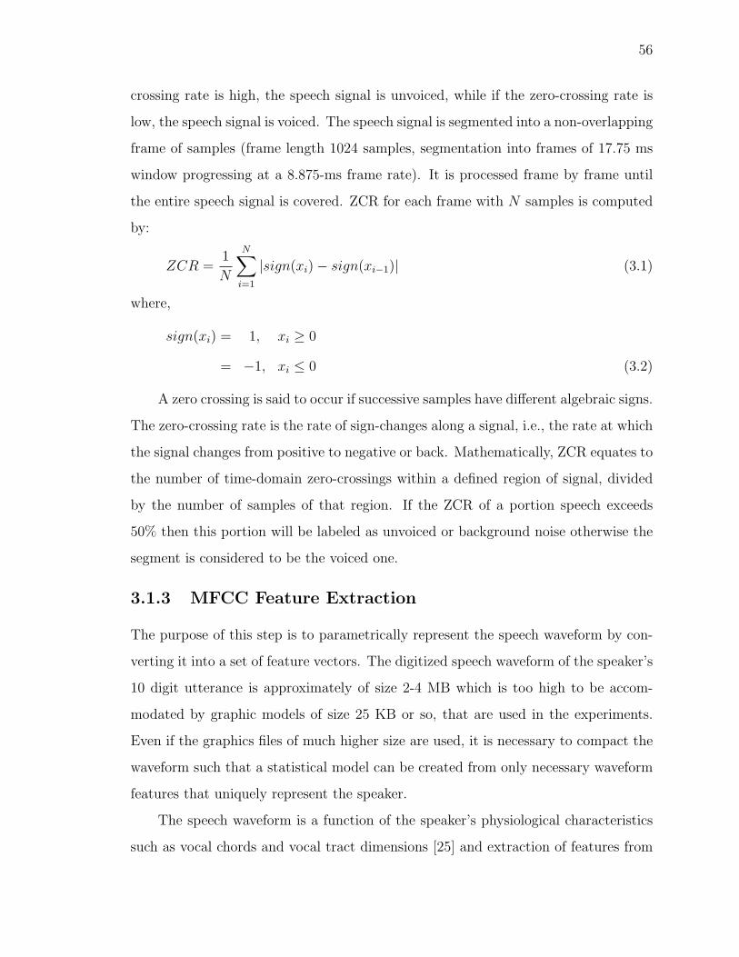
56
crossing rate is high, the speech signal is unvoiced, while if the zero-crossing rate is
low, the speech signal is voiced. The speech signal is segmented into a non-overlapping
frame of samples (frame length 1024 samples, segmentation into frames of 17.75 ms
window progressing at a 8.875-ms frame rate). It is processed frame by frame until
the entire speech signal is covered. ZCR for each frame with N samples is computed
by:
ZCR =1
N
N∑i=1
|sign(xi)− sign(xi−1)| (3.1)
where,
sign(xi) = 1, xi ≥ 0
= −1, xi ≤ 0 (3.2)
A zero crossing is said to occur if successive samples have different algebraic signs.
The zero-crossing rate is the rate of sign-changes along a signal, i.e., the rate at which
the signal changes from positive to negative or back. Mathematically, ZCR equates to
the number of time-domain zero-crossings within a defined region of signal, divided
by the number of samples of that region. If the ZCR of a portion speech exceeds
50% then this portion will be labeled as unvoiced or background noise otherwise the
segment is considered to be the voiced one.
3.1.3 MFCC Feature Extraction
The purpose of this step is to parametrically represent the speech waveform by con-
verting it into a set of feature vectors. The digitized speech waveform of the speaker’s
10 digit utterance is approximately of size 2-4 MB which is too high to be accom-
modated by graphic models of size 25 KB or so, that are used in the experiments.
Even if the graphics files of much higher size are used, it is necessary to compact the
waveform such that a statistical model can be created from only necessary waveform
features that uniquely represent the speaker.
The speech waveform is a function of the speaker’s physiological characteristics
such as vocal chords and vocal tract dimensions [25] and extraction of features from

57
the speech signal is such that they are primarily a function of speaker and not the
speech. Before performing signal parameterization, it is necessary to understand how
a speech wave is generated and what characteristics of this wave reflect the identity
of a speaker. The next two paragraphs discuss these two aspects briefly.
Speech production mechanism is explained by a simplified source-filter model
[138] according to which sounds are produced by the action of a filter (vocal tract)
on a sound source (glottis or vocal chords), technically equivalent to a convolution
process in signal processing. When air passes from the lungs through the vocal
chords (source) it is subject to rapid variations in pressure due to vibrations of the
vocal chords. Energy of this pressure wave is modified by its passage through the
vocal tract (filter), which acts as an acoustic filter that suppresses energies at certain
frequencies and amplifies energies at other frequencies.
The frequency and amplitude at which the air vibrates as it passes through the
vocal tract is determined by vocal tract shape and length, which vary from person to
person. The vocal tract dimensions are represented by a transfer function that can
be obtained from the frequency amplitude spectrum of the waveform. Peaks in the
spectral envelop correspond to formants which are resonant frequencies of the vocal
tract. The fundamental frequency and harmonics of a speaker’s spectrum reflect the
frequency of vibration of the source. The amplitude of the fundamental frequency and
the locations of the harmonics vary from speaker to speaker. Therefore, an acoustic
waveform carries an imprint of the source and filter that produced it and is unique
for every individual.
The Mel Frequency Cepstral Coding (MFCC) [21] approach to parameterize the
speech signal is a cepstrum (spectrum of a spectrum) based feature representation
technique. As illustrated in Figure 3.5, there are five stages to compute MFCC:
Windowing, Fourier Analysis, Mel-Filter Bank, Log Magnitude Spectrum, Cepstrum.
Stage 1 - Windowing: A speech signal is non-stationary because its characteristics
are not constant over long periods of time. However, when speech signal is examined
over short periods of time (5 to 100 milliseconds), its characteristics are fairly constant

58
Figure 3.5: MFCC Block Diagram
and the signal can be considered as a stationary signal. To extract this stationary
part of the signal, a Hamming window is used (see Figure 3.7, 3.8, and 3.9).
A symmetric Hamming window is given by:
w[n] =
{0.54 - 0.46cos( 2πn
L−1) , 0 ≤ n ≤ L− 1
0 , otherwise
Multiplying the window function with the time-varying speech signal not only
forces the signal to be periodic (which is a requirement for Fourier analysis) but
also reduces the leakage in the frequency domain which results in the signal energy
spreading over a wider frequency range as opposed to the actual signal frequency
that lies in a narrow frequency range. This leakage is a result of applying a Fourier
transform to non-periodic signals. Using a window that is shaped so that it approaches
zero at the beginning and the end, molds the signal into a periodic form thereby
reducing the leakage.
The Hamming window of width 1024 samples that extracts 17.75 milliseconds
windows (frames of length 1024 samples) from the original signal and is overlapped
for 512 samples such that the offset between successive windows is 8.875 milliseconds
is illustrated by Figure 3.6. There are a total of 337 frames for the pre-processed
signal, shown in Figure 3.4.
Stage 2 - Fourier Analysis: The next stage extracts the energy of the signal
in different frequency bands by applying the Discrete Fourier Transform (DFT) for
each windowed signal i.e. frame. A plot of the magnitude against the frequency is
visualized by the spectrum shown in Figure 3.10. This spectrum reveals the frequency
components for the pre-processed signal. For k frames of an original signal, the DFT

59
Figure 3.6: Extracting Frames from Preprocessed Discrete Signal
Figure 3.7: Frames of the Preprocessed Discrete Signal before Windowing
is given by the following equation:
X[k] =N−1∑n=0
x[n]e−j2πNkn (3.3)
where N represents the discrete frequency, X[k] is a complex number representing the
magnitude and phase of that particular frequency component of the original signal.
Stage 3 - Mel-Filter Bank: The sensitivity of the human ear is not the same for
all frequencies. The ear is less sensitive to frequencies higher than 1 KHz. The melody
scale approximates the frequency response of the human ear and places less emphasis

60
Figure 3.8: Hamming Window
Figure 3.9: Frames of the Preprocessed Discrete Signal after Windowing
on the higher frequencies. This stage warps the Fourier spectrum on a melody scale by
applying a mel-filter bank to the spectrum. Mel-filters are linearly spaced below 1KHz
and logarithmically spaced above 1KHz in the filter bank. These filters are triangular
shaped. Each filter from the bank collects energy from its respective frequency band.
The mel frequency can be computed from the acoustic frequency f by using the
following equation:
mel(f) = 1127 ln(1 +f
700) (3.4)
We use 39 filters in the filter bank. Figure 3.11 represents the mel-filter bank
used to capture energies from the Fourier spectrum of the windowed original signal.
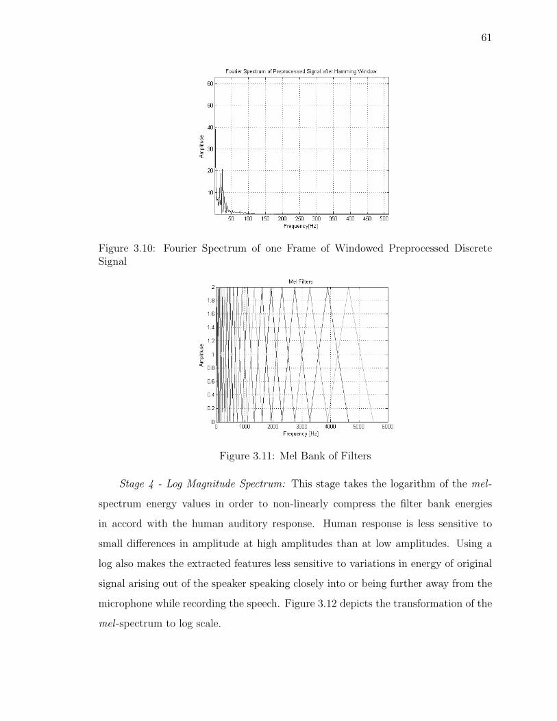
61
Figure 3.10: Fourier Spectrum of one Frame of Windowed Preprocessed DiscreteSignal
Figure 3.11: Mel Bank of Filters
Stage 4 - Log Magnitude Spectrum: This stage takes the logarithm of the mel -
spectrum energy values in order to non-linearly compress the filter bank energies
in accord with the human auditory response. Human response is less sensitive to
small differences in amplitude at high amplitudes than at low amplitudes. Using a
log also makes the extracted features less sensitive to variations in energy of original
signal arising out of the speaker speaking closely into or being further away from the
microphone while recording the speech. Figure 3.12 depicts the transformation of the
mel -spectrum to log scale.

62
Figure 3.12: Log of Mel Spectrum
Stage 5 - Cepstrum: This stage takes the inverse DFT of the log magnitude of
the spectrum of a windowed frame of the original signal to get a cepstrum, which is
shown in Figure 3.13. The inverse DFT is computed by the equation below:
c[n] =N−1∑n=0
log
(∣∣∣∣∣N−1∑n=0
x[n]e−j2πNkn
∣∣∣∣∣)ej
2πNkn (3.5)
The cepstral representation characterizes the vocal tract (lower cepstral values)
and the source (higher cepstral values) [19]. Peaks in the lower frequency compo-
nents of the cepstrum represent the formants while peaks in the higher frequency
components are caused by the fundamental frequency and harmonics.
MFCC feature extraction takes the first 12 cepstral values that represent the vocal
tract filter distinctly separated from information about the vocal source. Each frame
of the original signal is represented by a 12-dimensional feature vector consisting of
MFCCs i.e., x = x1, x2, x3, . . . x12. Figure 3.14 illustrates the MFCC cepstral features.
3.1.4 GMM Feature Representation
The 12 mel cepstral feature vectors representing spectral information are extracted
from the speech waveform every 17.75 milliseconds. Each of the 337 frames are
represented by 12 MFCC features. A data density plot (histogram) of the first MFCC
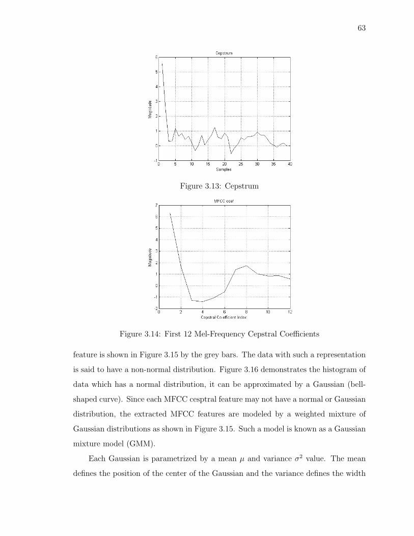
63
Figure 3.13: Cepstrum
Figure 3.14: First 12 Mel-Frequency Cepstral Coefficients
feature is shown in Figure 3.15 by the grey bars. The data with such a representation
is said to have a non-normal distribution. Figure 3.16 demonstrates the histogram of
data which has a normal distribution, it can be approximated by a Gaussian (bell-
shaped curve). Since each MFCC cesptral feature may not have a normal or Gaussian
distribution, the extracted MFCC features are modeled by a weighted mixture of
Gaussian distributions as shown in Figure 3.15. Such a model is known as a Gaussian
mixture model (GMM).
Each Gaussian is parametrized by a mean µ and variance σ2 value. The mean
defines the position of the center of the Gaussian and the variance defines the width

64
Figure 3.15: Gaussian Mixture Model with 20 Gaussians for the first MFCC
Figure 3.16: Data with normal distribution approximated by a Gaussian
of the Gaussian. Figure 3.17 demonstrates Gaussian distributions with different pa-
rameters µ and σ2.
Figure 3.17: Gaussian distributions with different mean µ and variances σ2
A univariate Gaussian represents one-dimensional data. Figure 3.18 shows mul-
tiple univariate Gaussians that are averaged to represent an arbitrary function with
a non-normal data distribution using a GMM for 1-dimensional data set. However,
the MFCC feature set is 12-dimensional, with 337 values for each dimension. Hence,
we use a mixture of multivariate Gaussians to model the multi-dimensional feature

65
set.
Figure 3.18: Gaussian Mixture Model of Univariate Gaussian distributions to approx-imate 1-dimensional feature set
Each individual multivariate Gaussian in the mixture model is parameterized by
a mean vector ~µ and covariance matrix Σ for the N -dimensional feature vector xn. A
model for M Gaussian mixtures, with each mixture having weight P (k) is given by
the equation:
p(xn) =M∑k=1
P (k)p(xn|k) (3.6)
where,
p(xn|k) =1
(2π)N2 |Σ|
12
e−12
(xn−~µ)TΣ−1(xn−~µ) (3.7)
represents the Gaussian distribution with |Σ| and Σ−1 are the determinant and inverse
of the covariance matrix, (xn − µ)T is the transpose of the matrix (xn − µ) and the
covariance matrix Σ is a diagonal matrix representing the variance of each dimension
only and all non-diagonal elements are zero (since the MFCC features have a nice
property of being uncorrelated).

66
However, for a given non-normal distribution i.e. data set of MFCC features
(Figure 3.15), the question arises which Gaussian accounts for which part of the dis-
tribution. Since it is not known which features from the MFCC set correspond to
which Gaussian, it is difficult to estimate the location (mean) and width (variance) of
each Gaussian in the mixture model. Learning approaches (such as neural networks)
and iterative techniques have been used to find which Gaussians correspond to which
data points and to determine what are the parameters for the individual Gaussian
distributions in the mixture model. In our approach, we use Expectation Maximiza-
tion(EM) [22] which is an iterative approach that is dominantly used to estimate the
best possible value of parameters (means, variances and mixture weights) for each
Gaussian in the distribution.
The EM approach is an optimization technique that estimates parameters for
each Gaussian in the mixture model. It starts off by choosing Gaussian models with an
initial set of parameters µk, Σk for k = 1, . . .M Gaussian distributions and assigning
equal initial probabilities (i.e. mixture weights that characterize which Gaussian is
accountable for which part of the data distribution) P (k) = 1M
to each Gaussian
model. Given this initial guess of parameters, the estimation step computes posterior
estimates for the mixture weights P (k|xn) (i.e. probability for each data point xn to
belong to the Gaussian mixture (µk,Σk). Given posterior estimates for the mixture
weights, the Gaussian distribution parameters that maximize the expectation of the
joint density for the data and the mixture weights is computed. The estimation and
maximization steps are re-iterated to improve the initially set probabilities until a
convergence to a good fit of Gaussians for representing the distribution is obtained.
Maximizing the expectation and the parameter reestimating steps give no guarantee
of how good the estimates will be, however, it has been proven that the estimates are
guaranteed to improve or at least not worsen with each iteration.
For the set of parameters θ = {P (k), µk,Σk} that need to be optimized using the
EM algorithm, the GMM with M multivariate weighted Gaussians is denoted by the

67
following equation:
p(xn, θ) =M∑k=1
P (k, θ)p(xn|k, θ) (3.8)
where:
• p(xn, θ) is the probability density function for the GMM,
• θ is the set of estimated parameters with the constraint∑M
k=1 P (k) = 1,
• P (k, θ) is the weight of the kth Gaussian or the probability that xn is being
generated by Gaussian (µk,Σk), and
• p(xn|k, θ) is the value of the kth Gaussian at xn assuming mean µk, variance Σk
and represents the conditional probability density function for xn conditioned
on xn being generated by the kth Gaussian.
The posterior probability P (k|xn) can be computed from p(xn|k) by Bayes’ for-
mula:
posterior =prior ∗ likelihood
evidence(3.9)
P (k|xn, θposterior) =P (k, θprior)p(xn|k, θprior)
p(xn, θprior)(3.10)
Substituting Equation 3.8 in the denominator, we get the following:
P (k|xn, θposterior) =P (k, θprior)p(xn|k, θprior)∑Mk=1 P (k, θprior)p(xn|k, θprior)
(3.11)
The next step is to estimate the true probability densities by maximizing the
logarithm of the joint density for xn and k. Unknown probability density p(xn, θ) can
be decomposed as joint and conditional densities:
p(xn, θ) =M∑k=1
P (xn, k|θ) =M∑k=1
P (k|θ)p(xn|k, θ) (3.12)

68
Expression for the log of joint density is written as:
J = logP (xn, k|θ) = log[P (k|θ)p(xn|k, θ)] (3.13)
Expectation of the log joint density is written as:
Q(θprior, θposterior) =N∑n=1
M∑k=1
P (k|xn, θprior) log p(xn, k|θposterior) (3.14)
where,
the first term P (k|xn, θprior) is given by Equation 3.11,
the second term is determined by Equation 3.12 and the initial/subsequent guess/estimates
for P (k|θ),
θprior is the set of parameters used to determine the distribution and
Q(θprior, θposterior) is the objective function that is maximized by assigning its partial
derivatives taken over each of the parameters of θ to zero.
The new estimates for parameters µk, Σk and P (k|θposterior) are computed by the
following equations:
µk =
∑Nn=1 P (k|xn, θprior)xn∑Nn=1 P (k|xn, θprior)
(3.15)
Σk =
∑Nn=1 P (k|xn, θprior)(xn − µk)(xn − µk)T∑N
n=1 P (k|xn, θprior)(3.16)
P (k|θposterior) =1
N
N∑n=1
P (k|xn, θprior) (3.17)
In approximately 10 iterations the algorithm finds the means and covariances of Gaus-
sians that correctly estimate the probabilities of which Gaussian represents which data
points. Figure 3.15 illustrates the GMM for the 12 MFCC coefficients.
The speaker model (voice print), is the aggregate of the parameter values λ =
{P (k), µk,Σk} of the Gaussian mixture model.

69
Figure 3.19: Gaussian Mixture Models with 20 Gaussians for all 12 MFCCs
3.1.5 Error Correction Encoding
The 3D model acts as a host that carries the watermark and can be subject to signal
processing operations such as noise. Therefore, this host is considered as a noisy
communication channel via which the embedded voice print data is transmitted and
gets corrupted, as per Shannon’s theory of communication [131]. In order to en-
sure the integrity of the voice print data, error correcting codes are used to encode
the watermark. We selected Reed-Solomon codes [118] for error correction. Reed-
Solomon codes are an important subclass of the non-binary BCH (Bose-Chaudhari-
Hocquenghem) [111] codes and operate over the Galois Field [74] of arithmetic. Reed-
Solomon codes are chosen because they have a simply-implemented decoding proce-
dure, can detect and correct large numbers of missing bytes of data, and require the

70
least number of extra error correcting code bytes for a given number of data bytes. In
addition, this coding scheme provides superior burst error correcting capability while
maintaining an excellent ability to correct random errors [142].
Reed-Solomon (RS) coding scheme generates a N -byte codeword from a K-byte
message. A t-error correcting RS code with symbols from Galois Field GF(2m) has
the following parameters:
• Block length: N = 2m−1 bytes
• Message size: K bytes
• Parity-check size: N −K = 2t bytes
For example, when t = 2, four redundant check bytes will be appended to the
K message byte, m0,m1, . . .mk−1, to form a RS codeword of size N = K + 4. The
check bytes are computed from the message byte using the following equation:
C(x) = M(x) ∗ x2t|g(x)| (3.18)
where:
• M(x) = m0xk−1 +m1x
k−2 + . . .+mk−1x+mk is the message polynomial,
• C(x) = c0x3 + c1x
2 + c2x1 + c3 is the check polynomial, and g(x) = (x+α1)(x+
α2)(x+ α3)(x+ α4) is the generator polynomial
The Reed-Solomon code is performed in the Galois Field GF(28), where α is the
primitive element that satisfies the primitive binary polynomial:
p(x) = x8 + x4 + x3 + x2 + 1 (3.19)
The codeword N constitutes a robust voice print since the error correction en-
coding adds redundancy to the voice print data to enable it to withstand attacks.
This voice print is used as the watermark, which is denoted by W .

71
3.2 3D Mesh Model Watermarking Algorithm
3.2.1 Watermark Embedder
The proposed technique estimates local curvature variation of the surfaces in the
3D mesh model and is similar to related work in that it employs surface normals
based approach. The curvature or smoothness of a surface is used as a 3D perceptual
measure to embed the watermark. Smooth surfaces can imperceptibly accommodate
a watermark as opposed to flat surfaces or edges (sharp curves). The variation in
the direction of surface normals is used to measure the smoothness of a surface.
Figure 3.20 outlines the steps of the watermarking algorithm.
Figure 3.20: Watermarking Process
Normalizing and Shifting of 3D Model
Normalization of the 3D model is a pre-processing step that makes the watermark
retrieval process invariant to changes in the orientation, translation, and scale of the
watermarked 3D model. For translation invariance, the center of mass (the mean

72
vector of all vertices) is shifted to the origin of the rectangular co-ordinate system
[67]. For rotation invariance [133], the eigenvectors of the 3D model are used to
represent the principal component axes of the model and are aligned to coincide with
the co-ordinate axes. To achieve scale invariance, the average distance of the vertices
from the center of mass is computed to determine the scale factor [77], which is used
during the retrieval process to normalize the model and compensate for scaling.
Finding Vertex Smoothness Measure
The mesh model is collection of triangular facets that approximate the 3D object.
Figure 3.21 shows the mesh structure of a textured Horse model.
Figure 3.21: 3D Model of Horse and the Mesh Representation
Figure 3.22 highlights the 1-ring neighborhood of a set of vertices in the model.
All the vertices that a vertex under consideration is connected to, is called the 1-
ring neighborhood of a vertex. The curvature for each vertex’s 1-ring neighborhood
surface is estimated to determine whether the vertex can accommodate the watermark
without causing any perceptual distortion to the model.
Figure 3.23 demonstrates the direction of the normals (in blue) to each face of
the model. Since only the face normals in the 1-ring neighborhood of each vertex of
the model are considered, the smoothness measure is local.
The following steps are implemented to compute the local smoothness measure:
Step 1: Consider a vertex v from the mesh model as shown in Figure 3.24. Let M

73
Figure 3.22: 1-Ring Neighborhood(highlighted in red) of Vertices
Figure 3.23: Face Normals(in blue)
be the number of its adjacent faces (M = 6 for the vertex v in Figure 3.24). The
normals Ni to each face Fi which is formed by v and its neighboring vertices vi is
computed by taking the cross-product of the two edges of the face.
Step 2: Shift the face normals to pass through v. Find the eigen normal N of
all the normals passing through v by computing the eigen-vectors from the eigen-

74
Figure 3.24: Eigen Normal N derived from 6 Face Normals
decomposition of the covariance matrix of all these surface normals. The eigen-vector
corresponding to the maximum eigen-value constitutes the eigen-normal, as shown in
Figure 3.25.
Figure 3.25: Normals Shifted to Pass Through Vertex v
Step 3: Now compute angles αi between each pair of Ni and N . Figure 3.25
shows an angle α1 between the eigen vector N passing through a vertex v and a
normal N1 to a face which has v as one of is vertices.
αi = cos−1
(NiN
|Ni||N |
)(3.20)
Step 4: Compute the average of all the angles αi to give the local smoothness

75
measure.
αavg =1
m
M∑i=1
αi (3.21)
Similarly, the algorithm is implemented at all the vertices in the mesh, to obtain the
local smoothness measure for the entire model. If the region around the considered
vertex is flat, the angles αi will be small in magnitude since the face normals will
be almost parallel to the eigen normal. If the region represents a peak, the angle
between the face normal and the eigen normal through the vertex, αi will have a
larger magnitude and so the smoothness measure’s magnitude will be higher. Thus,
this parameter αi represents local geometry or shape of a surface or region.
The illustration of this method is shown in Figure 3.26. The color scale starts
with blue and ends with red, where red represents the most rough surface. Toolbox
graph [66] has been used to display the models in MATLAB.
Figure 3.26: Curvature Variation in the Horse Model
Bin Formation
Based on the observed values of smoothness measure obtained for the vertex under
consideration, the degree of smoothness variation is scaled to lie between 1 and 8.

76
These scaled values are labeled into three bins. This scaling is done on the basis
that the bins between 1 and 2 have a low smoothness measure, bins between 3 and
6 are have a moderate smoothness measure, and bins between 7 and 8 have a high
smoothness measure. Thus, different regions of vertex smoothness measure are clas-
sified in the model. The decision of choosing 8 bins (instead of 3) was made to allow
room for the algorithm for manipulation of the number of bins selected for embed-
ding the watermark. Preliminary experiments suggested that 8 bins provide sufficient
granularity of curvature variation to adjust appropriate bins for watermarking should
the algorithm fail to achieve imperceptibility while embedding the voice print in all
bins with moderate smoothness measure. In scenarios where the watermark caused
perceivable distortions in the 3D model, the number of selected bins with moderate
smoothness measure were lowered and the scaling factor (discussed in later sections)
was decreased by an order of 10−1. Figure 3.27 shows the model and color bar indi-
cating bins with pseudo colors (blue for the lowest variation and red for the highest
variation).
Figure 3.27: Bin Formation in Original Models

77
Selection of vertices for watermark insertion
Vertices lying in the regions which have moderate smoothness are selected to allow
imperceptible distortions in the final watermarked model. High values of the smooth-
ness measure represent very sharp changes such as edges. Low values correspond to
smooth or flat surfaces. Watermark insertion in these extreme high or low smooth-
ness regions is perceptible due to response of the Human Visual System. Figure 3.28
shows the selected vertices (in dark red) in the model.
Figure 3.28: Vertices Selected for Watermarking (in red)
Insertion of watermark
The robust voice print W is inserted as the watermark in the selected vertices. Water-
mark embedding is performed by altering the co-ordinate (x, y, z) of a vertex according
to the following formula:
v(x, y, z) = v(x, y, z) +KW (3.22)
where,
K = ScalingFactor,
W = WatermarkSequence. The corresponding watermarked vertex is denoted by v.

78
A scaling factor of 10−4 is used to embed the watermark values in the fourth decimal
place of the vertex coordinate. The watermark is embedded in x,y,z co-ordinates
therefore it is replicated thrice in the 3D model, thereby employing a secondary level
of redundancy in addition to the Reed Solomon error correction encoding.
Rescaling and Shifting
Finally, the model is re-shifted and re-oriented to its initial location in the co-ordinate
system. The watermark is inserted in the geometry of the model and modifies only
the locations of vertices, without changing the connectivity of vertices. As it can be
seen from Figure 3.29, there is minimal perceptible distortion between the original
model and the watermarked model.
Figure 3.29: The Original and Watermarked Model of Horse
3.2.2 Watermark Detector
The watermark retrieval process requires the semi-blind key as well as the water-
marked model to extract the watermark. Figure 3.30 outlines the extraction process.
Prior to watermark retrieval, the center of mass of the watermarked 3D model is
determined and subtracted from the center of mass of the original model to determine
the translation on the x,y and z coordinates of the watermarked vertices. The model
is then shifted to compensate for this translation. The extent of scaling in the x,
y and z directions is computed by dividing the average distance of the x, y, and z

79
Figure 3.30: Watermark Extraction Process
coordinates of the watermarked and original vertices from the center of mass of the
respective models. The normalization process [133] then re-scales and re-aligns the
model after determining the degree of rotation.
3.2.3 Error Correction Decoding
Error correcting codes are applied to retrieve the voice print from the extracted
watermark. The extracted watermark is decoded by the Reed-Solomon decoder and
the original voice print data is recovered depending on the extent of damage caused to
the watermark. The decoder can either correct errors (half as many as parity/check
bytes appended to the original voice print) or fail to make corrections, in which case
the verification module assists in determining the extent of damage and whether the
extracted voice print can still be used to verify the user.
3.2.4 Verification Module
This step measures - i) the extent of similarity between the embedded and extracted
watermark, and ii) whether the MFCC features extracted from a newly acquired
voice sample from the user represent the same speaker whose voice print has been
embedded as the watermark.
The correlation coefficient Corr that gives the extent of similarity between the

80
embedded watermark W and the recovered watermark W ′ is computed by:
Corr =
∑WW ′ −
(∑W∑W ′
n
)√(∑
W 2 − (∑W )2
n
)(∑W ′2 − (
∑W ′)2
n
) (3.23)
where, n is the size of the watermarks.
This correlation coefficient is a number between -1 and +1 which measures the
degree to which two variables are linearly related. If there is perfect linear relationship
with positive slope between the two variables, the correlation coefficient will be +1.
If there is a perfect linear relationship with negative slope between the two variables,
the correlation coefficient will be -1. A correlation coefficient of 0 indicates that there
is no linear relationship between the variables.
The acoustic likelihood measure of the extracted MFCC features from the user’s
voice sample acquired at access time, with the extracted voice print(i.e. the speaker
model embedded into the 3D model) is computed by:
LogLikelihood = log[P (k|θ)p(xn|k, θ)] (3.24)
The value of this log likelihood measure suggests if the extracted features from the
acquired voice sample match the speaker model represented by the GMM embedded
as the watermark. When a speaker’s GMM is evaluated for a set of MFCC features,
only that speaker’s features contribute significantly to the likelihood value. If this
value falls within a threshold of ±1 (which allows for intra-individual variations in
voice) of the original log likelihood measure derived during the enrollment phase, then
the user is authenticated and allowed to access the 3D model. Changing the value of
the threshold results in different FRR and FAR, as demonstrated by the experiments
in Chapter 5.
3.3 Proposed Digital Rights Management Model
A high-level overview of the proposed DRM system framework is outlined in Figure
3.31. This process model [95] shows the basic processes in the DRM system and the
logical work flow from creation to consumption of the graphic file.
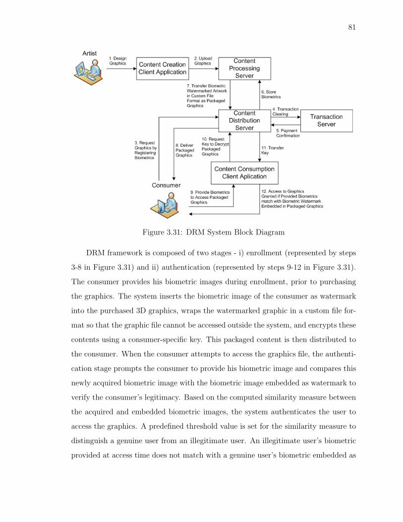
81
Figure 3.31: DRM System Block Diagram
DRM framework is composed of two stages - i) enrollment (represented by steps
3-8 in Figure 3.31) and ii) authentication (represented by steps 9-12 in Figure 3.31).
The consumer provides his biometric images during enrollment, prior to purchasing
the graphics. The system inserts the biometric image of the consumer as watermark
into the purchased 3D graphics, wraps the watermarked graphic in a custom file for-
mat so that the graphic file cannot be accessed outside the system, and encrypts these
contents using a consumer-specific key. This packaged content is then distributed to
the consumer. When the consumer attempts to access the graphics file, the authenti-
cation stage prompts the consumer to provide his biometric image and compares this
newly acquired biometric image with the biometric image embedded as watermark to
verify the consumer’s legitimacy. Based on the computed similarity measure between
the acquired and embedded biometric images, the system authenticates the user to
access the graphics. A predefined threshold value is set for the similarity measure to
distinguish a genuine user from an illegitimate user. An illegitimate user’s biometric
provided at access time does not match with a genuine user’s biometric embedded as

82
the watermark, so the system denies access to the graphics.
If the biometric watermark can’t be retrieved from the graphic file, the system
denies access to the graphic file. Therefore, the system does not rely on the assump-
tion that the biometric watermark is intact and has not been destroyed by hackers.
This feature discourages consumers from tampering with the packaged graphics. If
illegal copies of the artwork are redistributed by a legitimate user, the biometric
watermark travels with the artwork and secures it from illegitimate usage. This is
because the custom file format prevents consumers from accessing the file outside the
DRM system, and the authentication stage of the system sieves legitimate users from
illegitimate users. Therefore, the biometric watermark protects the graphics content
from being used by anyone other than the valid user.
If the system is compromised and the artwork is distributed and accessed by any-
one other than the legitimate user, the embedded biometric serves as a tracer. The
pirated graphic file is examined for the embedded biometric watermark. If the bio-
metric watermark has not been tampered with, it assists in tracing back illegitimate
redistribution to the traitor in the distribution chain and suing the responsible indi-
vidual for piracy. Privacy concerns over sharing one’s biometric trait along with the
purchased protected graphic content on peer-to-peer(P2P) networks, prevents large
scale piracy of the artwork.
In the event of compromised biometrics, since a biometric trait cannot be revoked,
the framework has the provision to support multiple biometrics so the compromised
trait is replaced by an alternative trait. Furthermore, upon receiving notification of
compromised biometrics from the user, the server de-activates the user-specific key
thereby locking out access to files previously encrypted with this key and issues a
new key for the user. This new key is used to encrypt files previously purchased
by the user, so only the legitimate user is able to access these files in spite of the
compromised biometrics.

83
3.3.1 DRM System Architecture
The architectural design of the system, see Figure 3.32, has been motivated by various
DRM system architectures [9, 28, 31, 37, 59, 62, 75, 89, 113, 116]. The system uti-
lizes a client-server protocol for implementation as shown in Figure 3.32 and involves
a custom file format associated with a DRM enabled graphics design/consumption
application. 3D graphics files are sold in various formats , such as 3ds (3D Studio),
mb (Maya), lwo (Lightwave), c4d (Cinema 4D). A file format’s (e.g. 3ds) native
graphics design software (e.g. 3D Studio) is not equipped with DRM functionali-
ties. Embedding biometric watermarks in existing file formats requires the associated
graphics design software to incorporate a DRM plug which enforces access control.
Graphics designed and sold prior to installation of this plug-in are DRM-free and
are not protected from piracy. Biometric watermarks from protected graphics can
be easily removed by using DRM-free versions of the same graphic. Since backwards
compatibility and DRM can’t go hand in hand, it necessitates the need for a custom
3D graphic file format and a customized graphics design application equipped with
DRM modules. The custom file format enables access control by notifying a graphics
consumption application that a file is DRM enabled. The custom file format is a just
way to bind the graphics to the DRM system in order to prevent users from bypassing
the access control mechanism. The custom file format also assists in content editing,
logging, and system renewability.
The proposed DRM system has five components: Content Creation, Content Pro-
cessing, Transaction Management, Content Distribution, and Content Consumption.
Functionality of each component is specified below.
Content Creation
Artists use a graphics design application to create the artwork. The design software
has DRM capabilities after installation of a DRM plug-in. Alternatively, a proprietary
DRM system based on a proprietary 3D file format can be developed that supports
design of the graphics in multiple native formats (3ds, mb, lwo) which then undergo

84
Figure 3.32: DRM System Components
DRM compliant format conversion. Figure 3.32 illustrates the functionalities of this
component. The plug-in for the artists will include the watermark embedder, detector
and matcher components, and an interface to connect to the graphics repository on
the content server.
Content Processing
The user enrollment interfaces provided by the content distribution component (see
Figure 3.33) securely transfer the acquired biometric trait of the user to the biometric
template generation module on the content server. This module generates a biometric
print from the biometric samples provided by the user. Due to privacy concerns [57],
the template is encrypted and then stored in the biometric templates repository along
with an associated user identifier. The packaging module is responsible for conversion
of graphics to custom file format representation. This module populates meta data in
a header with default values. The graphic content is watermarked with an encrypted
version of the biometric template. A key is generated for the user, stored in the key
repository, and linked with the user’s biometric template. The packager encrypts the
content along with the meta data using this key so that the content is scrambled and
made unreadable. The packaged content is ready for distribution to the user.

85
Figure 3.33: Content Processing
Transaction Management
This component handles the user registration, commerce, and billing activities. It
includes a module for interaction with an external payment service to handle the
financial aspects of the purchase transaction.
Content Distribution
The main function of this component is trading and registration of the user. It main-
tains a website which acts as the interface between the consumer and the content
provider. It provides interfaces to register the user, accept payment information,
capture user’s biometric samples and securely transfer the acquired information to
the Transaction Management component. Distribution of the packaged graphics to
the clients is also handled by this component. Distribution is carried out by provid-
ing download interfaces using either HTTP, FTP, or SMTP protocols. Content is
delivered over a secure transmission channel.

86
Figure 3.34: Content Consumption
Content Consumption
Figure 3.34 outlines the content consumption component of the proposed DRM sys-
tem. The client-side DRM enabled graphics consumption software is responsible for
authorizing rightful users to access the purchased graphics. When an attempt is made
to access the file by the end user, the 3D content consumption application prompts
the consumer to provide his/her biometric trait. The DRM plug-in installed at the
client application generates a biometric template from the acquired sample, encrypts
it and then sends it to the server along with the user identifier to request the key as-
sociated with the user to decrypt the file contents. The plug-in used by the consumer
application will only have the watermark detector and matcher component. The en-
crypted biometric template is compared with the extracted biometric watermark to
validate legitimacy of the user. A match between the captured biometric template
and the embedded template grants access to the user, while a mismatch locks down
the graphic file. If the watermark detector is unable to retrieve the watermark it
denies access to the file. The plug-in provides access management by tracking save
as, modify and save, cut, copy, paste operations on the graphics file. It keeps track
of the user activity in regards to modifying and copying the graphics to new files and

87
updates the header of the graphics file with appropriate logging information. This
logging assists the plug-in to maintain the presence of the biometric watermark in the
graphics content regardless of modifying or saving of the graphics to a new file. If the
system is compromised and the file is distributed and accessed by anyone other than
the legitimate user, the embedded biometric serves as a tracer. The pirated graphic
file is examined for the embedded biometric watermark. If the biometric watermark
has not been tampered with, it assists in tracing back illegitimate distribution to the
traitor in the distribution chain and suing the responsible for piracy.
The system employs a locking and logging mechanism and handles security issues
by using encryption to address the privacy and maintain anonymity of users. The
robustness of the system is based on the performance characterization of biometrics
which has been discussed in detail in [106].
3.3.2 Custom File Format
Figure 3.35 illustrates the proposed file format which includes a header and the wa-
termarked graphics content. The header comprises of 7 fields that serve as meta data.
Figure 3.35: Header Fields
The field for version number is used to allow future modifications to the file format.
To avoid a file from being watermarked twice, the watermark field indicates whether
the file has been watermarked or not. The number of times access is denied to a file
based on the provided biometrics, is stored in the access denied count field. This is to

88
prevent illegitimate users from circumventing the system by repeated trial and error
attempts. The user is allowed 3 attempts to access the file using biometric authenti-
cation and then the Lock flag is set to disable the file. Access log stores the number
of attempts required to access the file for monitoring user activity, the date, time and
PC’s hardware identifier for the last successful access. The first time a user accesses
a file on a PC, the user is prompted to provide biometric samples. The biometric
print is encrypted and cached on the local store. Subsequent accesses on the same PC
utilize a locally cached copy of the biometric print. Each time the user tries to access
the file from a different PC, the hardware ID in the header is checked to prompt the
user for biometric sample acquisition. Activities of the user in terms of modifying and
copying the graphic content are recorded in the usage log field to notify the system
for taking incremental protection measures to watermark the modified or copied file.
Analogue attacks are addressed by the system by monitoring the screen capture flag.
Reserved field is included to accommodate tags for future use such as multiple wa-
termarks, reseller watermarks, transfer of watermark, and interoperability. Table 3.1
provides the description and values for the header fields.
3.3.3 Security Aspects of the DRM System
Security Model
The primary security goal of the DRM system is to prevent illegitimate access to the
legally distributed 3D graphics. The secondary goal of the system is to trace illegally
accessible graphics back to the buyer responsible for unauthorized redistribution.
According to Kerckhoff’s principle, the strength of a system should lie entirely in
the difficulty in determining the key and not in the secrecy of the algorithm. The
proposed system utilizes a consumer-specific key to encrypt/decrypt the custom file
format. The custom file format merely serves as a container for the raw graphics data
and the purpose of the key is to make it difficult for the adversary to segregate this
raw graphics data that is wrapped in the custom file format. The system is breached
if this key is accessible to the adversary, for the unprotected graphics data can be

89
Table 3.1: Header Fields of Custom File FormatByte Description Value0: Version 1, For current implementation2: Watermark 0 - File is not watermarked,
1 - File is watermarked3: Access Denied Number of Times Access to File is Denied
Count10: Lock 0 - File is Unlocked,
1 - File is Locked For Access11-51: Access Log Number of Attempts Required to Access the File
Date, Time and Machine’s Hardware Identifierfor Last Successful Access
52-56: Usage Log 00000 Default Value52 1 - File is Modified and Saved,53 1 - File is Saved As New Copy,54 1 - Copy (Ctrl-C Key pressed),55 1 - Paste (Ctrl-V Key Pressed),56 1 - Screen Capture (PrtScrn Key is Pressed)57 - 300 Reserved For Future Use
separated from the decrypted custom file format. Therefore, the system completely
relies on the secure storage of this key in order to protect the data.
The security assumption made by the system is that the communication between
the artist, the DRM client and servers, and the consumer takes place through a secure
channel in order to protect information from eavesdropping when it is transmitted.
Trust Model
• To ensure that the content server receives artwork from a genuine artist, the sys-
tem requires the artist to provide his digital certificate. Prior to uploading the
graphics to the content server. the artist signs and encrypts the graphics. The
server validates the integrity of the uploaded content by verifying the artist’s
signature and then decrypts the content for further processing. This validates
the content to be genuine and establishes trust between the artist and content
server.
• To obtain the user-specific key from the content server to decrypt the packaged

90
graphics, the content consumption client application requires that the buyer
must authenticate to prove his identity to the server by providing a user ID.
• The user’s authentication data and biometric data are only available to the user.
• The system will not share a user’s personal data with third parties.
• The framework handles security issues associated with biometric data by using
encryption to address the privacy and maintain anonymity of users.
Threat Model
Security Issues For The Server
The Content Server is prone to hacking. An adversary can exploit security flaws in
the server to obtain control over any one of the server repositories that store the bio-
metric templates, keys and unpackaged graphics, the packaging module and defeat
the system.
Security Issues For The Communication Channel
The communication channel is considered to be under the complete control of an
adversary who can break weak cryptography, exploit weak keys, knows the commu-
nication protocol, controls the network, can break into servers with security flaws,
download original content.
Security Issues For The Client’s Side
• The adversary has complete control over the user side and can hack the DRM
client consumption application. The client side watermark extractor or matcher
component can be replaced by an attacker-supplied component.
• The user-specific key acquired from the server is temporarily stored on the
client’s machine to decrypt the packaged graphics, and is vulnerable to exposure.

91
• It is possible to make an analogue copy of the output (e.g. reconstructing the
3D model from 2D images captured from the display screen). This can be
prevented by limiting the number of allowed screen captures.
• Attacks against the rendering application that replace part of the rendering
application so that once the content is decrypted, it can be captured and saved.
• A major threat to the system is compromised biometrics that lead to spoof-
ing attacks. When a user’s biometric trait is compromised (i.e. an adversary
obtains the biometric of a legitimate user without his consent or knowledge),
the adversary fraudulently gains access to the protected graphics file with the
legitimate biometric trait. Biometric-based authentication systems have been
criticized due to this vulnerability, since a biometric trait cannot be revoked.
The proposed framework addresses this security issue by supporting the use
of multiple biometric traits such that if one biometric trait is compromised, it
can be replaced by an alternative trait. Furthermore, since the DRM system
is an online system, the server deactivates the key generated for a user whose
biometric has been compromised thereby locking out access to files previously
encrypted with this key and issues a new key for the user. This new key is used
to encrypt files previously purchased by the user, so only the legitimate user is
able to access these files in spite of the compromised biometrics.

92
Chapter 4
Software Engineering DesignPrinciples
This chapter outlines the system assumptions, requirements, specifications along with
software engineering design principles concerned with the modularization and detailed
interfaces of the system elements.
4.1 System Assumptions
The system operation is based on the following assumptions:
1. The biometric trait is present in the user (which means that the user has a
voice).
2. The user is willing to offer his/her voice biometric samples to the system for
legitimate access control of watermarked 3D models.
3. The user is cooperative and utters the predetermined phrase while providing
voice samples during both enrollment and authentication phases. The system
does not check the validity of the spoken phrase should the user intentionally
change the spoken text.
4. The voice samples are acquired in a quite environment.
5. The acquired voice samples represent a single speaker audio stream. The system
does not support multi-speaker streams.

93
6. The user will not share voice recordings of the spoken phrase with others. The
security of the system is based on this assumption so that prerecorded voice
samples of legitimate user do not circumvent the system.
7. The system ignores variations such as different pitch that alters the speaking
manner, noisy voice samples due to the environment or communication channel
(voice acquired over telephone), speaking under stress or during sickness (cough,
cold, fatigue), and attempted mimicry.
8. The file formats that will be used are .wav for sound file input, .off format for
3D mesh models, ascii .txt representation for the biometric voice print.
9. The input .off file size is restricted to the range of 15KB - 2000KB. Most 3D files
smaller than 15KB are unable to accommodate a watermark that houses a voice
print (minimum size 1.17KB). 3D files over 2000KB require longer processing
times (over a couple of minutes) on a desktop PC.
4.2 Requirements Specification
The purpose of the requirements specification is to describe the functionality that the
Biometric Watermarking System (BWS) will support. The system requirement can
be categorized as non-functional and functional.
4.2.1 Non-Functional Requirements
The non-functional requirements are associated with the usability, reliability, perfor-
mance of the system, and system specifications.
Usability: BWS must meet usability goals set in regards to:
• Effectiveness: The system must always accept legitimate users and may falsely
accept non-genuine users depending on the FAR for a specific user.
• Efficiency: The system must not require an inordinate amount of the users’
effort for enrollment and authentication.

94
• Satisfaction: The system must be perceived as easy to use by the users.
• Learnability: The system must not require an inordinate amount of effort for
novice users to learn how to use it.
Performance: Watermarking and Accessing 3D Files: A model should be water-
marked and the user authenticated in a reasonable amount of time. Actual processing
time for a model will depend on variables such as file size and user interaction.
• Time should not exceed 120 seconds per 3D model 95% of the time for files less
than 500KB.
Reliability: The system must have the ability to operate correctly over time, includ-
ing consistent stability of the system at all times.
Hardware and Software Requirements: The hardware and software requirements
of the system are outlined in Figure 4.1.
Figure 4.1: Hardware and Software Requirements

95
4.2.2 Functional Requirements
This section has a list of all specific requirements that are to be implemented by
BWS. Each functional requirement has been assigned a reference number, starting
with the characters - DT, PR, for traceability to other system artifacts.
Data Requirements
• Graphics File Format (F DT 01): BWS must support the Open File Format
(.off) for 3D models.
• Characteristics and quality of the recorded voice (F DT 02): A 2 channels stereo
sound signal with a bit rate of 1411kbps, sample size of 16 bits and an audio
sampling rate of 44 KHz is captured in .wav format.
Process Requirements
• Imperceptible watermark (F PR 01): The system embeds a voice print of the
user into a 3D model such that watermarked 3D mesh model looks like the orig-
inal model and it should not reveal any clues of the presence of the watermark.
• Semi-Blind watermarking technique (F PR 02): The system does not require
the original unmarked model to extract the watermark from the watermarked
media but makes use of a key, that stores the locations and original values of
the vertices that are modified by the watermarking scheme, in addition to the
original watermark.
• Semi-Fragile watermark (F PR 03): A semi-fragile watermark is inserted into
the host model and can withstand certain attacks (noise, cropping, smoothing)
but not all. The watermarking scheme does not support 3D content editability,
mesh subdivision, decimation and remeshing operations.
• Text and speaker dependent voice print (F PR 04): The voice capture process
is text dependent as all the speakers have to speak a predetermined text. The
speech waveform is then converted to a parametric representation i.e. feature

96
vectors. Extraction of features is done such that they are primarily a function
of speaker.
• Variable speaking rate (F PR 05): The voice print extracted from the recording
has to independent of the length of duration of recorded voice sample (talking
speed of the speaker). The system achieves insensitivity to speaking rate by
pre-processing the acquired voice sample to eliminate silence thereby accom-
modating slow, moderate, and fast speakers which generate voice samples of
different duration.
• Constant size voice print (F PR 06): Since the voice print is derived from the
Gaussian mixture model of the mel-frequency cepstral co-efficients of the voice
signal, the voice print always assumes a fixed size of values irrespective of who
the speaker is.
• Access Control Decision (F PR 07): BWS will determine if a user for a 3D model
is authentic or not. The system provides a decision on whether to accept or
reject the user based on the comparison of the voice sample provided by the user
during authentication with the voice print generated during user enrollment.
4.3 System Design
Figure 4.2 demonstrates a high-level layered architecture of the system. There are
six functional layers - Voice Acquisition, Watermark Generation, Watermark Embed-
ding, Voice Parametrization, Watermark Detection, and Access Control. The system
is divided into two sub-systems - Enrollment and Authentication subsystems.

97
Figure 4.2: System-Level Layered Architectural Diagram
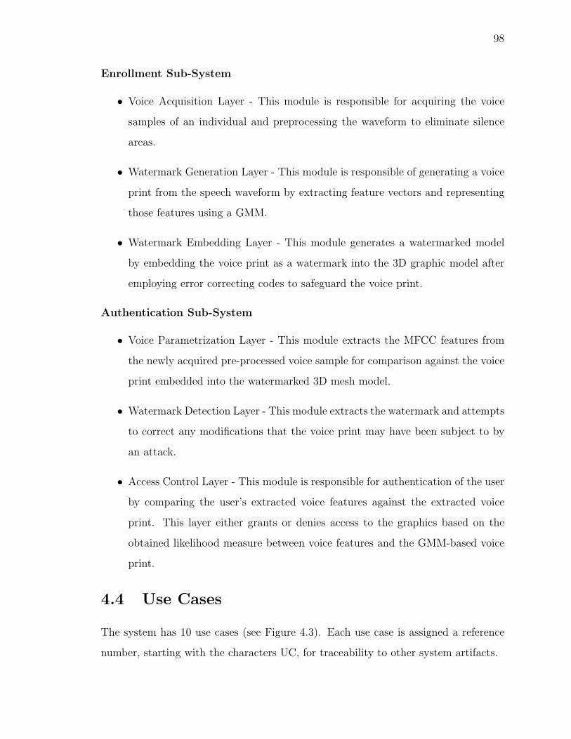
98
Enrollment Sub-System
• Voice Acquisition Layer - This module is responsible for acquiring the voice
samples of an individual and preprocessing the waveform to eliminate silence
areas.
• Watermark Generation Layer - This module is responsible of generating a voice
print from the speech waveform by extracting feature vectors and representing
those features using a GMM.
• Watermark Embedding Layer - This module generates a watermarked model
by embedding the voice print as a watermark into the 3D graphic model after
employing error correcting codes to safeguard the voice print.
Authentication Sub-System
• Voice Parametrization Layer - This module extracts the MFCC features from
the newly acquired pre-processed voice sample for comparison against the voice
print embedded into the watermarked 3D mesh model.
• Watermark Detection Layer - This module extracts the watermark and attempts
to correct any modifications that the voice print may have been subject to by
an attack.
• Access Control Layer - This module is responsible for authentication of the user
by comparing the user’s extracted voice features against the extracted voice
print. This layer either grants or denies access to the graphics based on the
obtained likelihood measure between voice features and the GMM-based voice
print.
4.4 Use Cases
The system has 10 use cases (see Figure 4.3). Each use case is assigned a reference
number, starting with the characters UC, for traceability to other system artifacts.

99
Figure 4.3: Use Case Diagram
• AcquireVoiceSamples (UC01): The user provides the system with voice samples
in .wav format for a predefined utterance. The user presses the Provide 3 Voice
Samples button to upload the .wav files into the system.
• SignalPreprocessing (UC02): The system eliminates silent regions from the
waveform when the user presses the Voice Signal Pre-Processing button. This
step enables the voice print formulation process to be independent of the pace at
which the predetermined phrase was spoken during the voice acquisition phase.
The display area is updated with the representation of processed signal.
• FeatureExtraction (UC03): The user presses the MFCC Feature Extraction but-
ton to extract features representing the identity of the user.

100
• SpeakerModelling (UC04): The user presses the GMM Speaker Model button
to instruct the system to use the extracted features in the previous step for
generating a GMM that constitutes the user’s voice print.
• GenerateWatermark (UC05): The user presses Generate Watermark button to
encode the voice print using error correction routines in order to protect its data
from attacks.
• Input3DModel (UC06): The user presses the Input 3D Mesh Model button to
upload the 3D model for watermarking. The display area is updated with a
rendering of the graphic file.
• WatermarkInsertion (UC07): The user presses the Watermark Insertion button
to enable the system to inserts the watermark into the previously selected 3D
model.
• Display3DModel (UC08): The user pushes the DRM Protected 3D Model button
to display the watermarked model in the bottom right axis on the interface.
• ProvideVoiceSample (UC09): The user presses the Provide Voice Sample button
to upload a voice sample with the predetermined utterance. The system pre-
processes this voice sample and extracts user specific features from it.
• AccessControlDecision (UC010): The user presses the Access Control Decision
button for the system to provided a decision regarding granting or denying
access to the graphics file. The access control decision is displayed in the center
bottom area of the authentication interface panel.
4.5 Requirements Traceability Matrix
Figure 4.4 shows the mapping between the functional requirements and the corre-
sponding use cases which implement the requirement. This traceability matrix is
used to check if the requirements are being met.

101
Figure 4.4: Requirements Traceability Matrix
4.6 User Interface
Figure 4.5 illustrates the main GUI of the system. The GUI provides an interface
with buttons and axes to interact with the user and display intermediate phases
of the biometric watermarking process. The GUI is divided into two sections to
represent the two phases of the system - Enrollment and Authentication. For the
enrollment phase, the end user only needs to interact with the system using the
first button (Provide 3 Voice Samples) which prompt the user to upload his voice
samples, the Input 3D Mesh Model button which prompts the user to upload the
3D model that needs to be watermarked, and the last button (DRM Protected 3D
Model) which inserts the voice biometric watermark into the uploaded 3D model
and provides a rendering of the watermarked 3D model in the right bottom display
area. The remaining intermediate buttons have been provided to enable - i) users
to understand the various steps involved in the biometric watermarking process and
ii) visualize the intermediate steps of signal pre-processing, MFCC feature extraction
and GMM speaker modeling. The right panel does not provide an interface for the
intermediate steps of watermark extraction solely for the purpose of giving users a
feel of the simplicity of interacting with the system during the authentication phase.
Figure 4.6 depicts one of the intermediary steps that displays the speech waveform in
red, representing the pre-processed voice signal.

102
Figure 4.5: Main GUI - The left panel provides an interface for user enrollment. Theright panel provides an interface for user authentication.
Figure 4.6: Voice Signal Preprocessing - The axis on the upper left corner shows aplot of the voice signal (in red) after silence removal.

103
Figure 4.7 portrays a plot of the 12 MFCC coefficients of the first frame from the
acquired voice sample.
Figure 4.7: MFCC Feature Extraction - The axis on the upper left corner plots the 12MFCC coefficients corresponding to the first frame of the first voice sample providedby the user.

104
Figure 4.8 enables users to see the GMM in one dimension plotted for the first
MFCC coefficient acquired from all the frames of the enrollment voice samples.
Figure 4.8: GMM Speaker Model - The axis on the upper left corner plots the Gaus-sian mixture model for the first MFCC coefficients of all the frames from the threevoice samples..
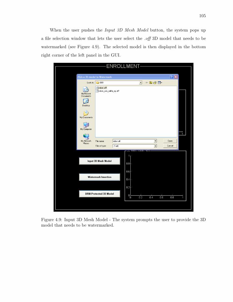
105
When the user pushes the Input 3D Mesh Model button, the system pops up
a file selection window that lets the user select the .off 3D model that needs to be
watermarked (see Figure 4.9). The selected model is then displayed in the bottom
right corner of the left panel in the GUI.
Figure 4.9: Input 3D Mesh Model - The system prompts the user to provide the 3Dmodel that needs to be watermarked.

106
Figure 4.10 demonstrates the 3D model watermarked using the voice signal plot-
ted in red.
Figure 4.10: DRM Protected 3D Model - The axis on the upper left corner shows aplot of the voice signal used for generating the voice print. The bottom right displayarea shows the watermarked 3D model.

107
Figure 4.11 illustrates the system access control decision for a given voice sample
and watermarked 3D model, which are provided by the user in the right authentication
panel of the main GUI.
Figure 4.11: Access Control Decision - The user has only 3 verification attempts togain access to the 3D mesh model. Since the FRR of the system is 0.6667 (computedfor a total of 3 verification attempts), the system is guaranteed to grant access tolegitimate user within the three trials.

108
Figure 4.12 displays the system’s decision to grant access to a DRM protected
(biometric watermarked) 3D model.
Figure 4.12: Access Control Decision - A legitimate user is granted access to thewatermarked 3D model upon providing a voice sample.

109
Chapter 5
Experimental Results
Evaluation of System Performance
The proposed scheme embeds a biometric system within a watermarking system.
Therefore, this chapter lists several experiments which are performed to: i) evaluate
the effectiveness of the watermarking scheme, ii) determine parameters for the voice
biometric system, and iii) test the feasibility of the overall system with the objective of
determining the extent of attacks the biometric watermark can withstand to correctly
verify the legitimacy of a user.
5.1 Effectiveness of the Watermarking Scheme
Watermarking algorithms are evaluated in terms of perceptibility, embedding capacity,
and robustness of the watermark to attacks. Perceptibility is the perceivable distortion
caused to the 3D model after embedding the watermark. It is measured by the
Hausdorff distance between the original and watermarked model. Embedding capacity
is the amount of data that can be embedded as watermark into the 3D model. It
is expressed in terms of the count of vertices that are modified to accommodate the
watermark. Generally, the size of the watermark, commonly referred to as the payload
size, also indicates the embedding capacity. Robustness is the ability of the watermark
to withstand attacks such as affine transformations, cropping, additive noise, vertex
reordering, mesh simplification, remeshing, mesh smoothing, and watermark removal.
It is expressed in terms of a correlation coefficient which indicates the similarity

110
measure between the embedded watermark and the extracted watermark that has
been affected by the aforementioned attacks..
5.1.1 Perceptibility and Embedding Capacity
The 3D mesh models used for our experiments are shown in Figure 5.1. Table 5.1 lists
the perceptibility measure and the capacity of the proposed watermarking technique.
Figure 5.1: Original and Watermarked 3D Models
Table 5.1: Comparison Of Original Model With Watermarked ModelModel Total # of Hausdorff DistanceName # of Watermarked Max Mean RMS
Vertices Vertices Dist. Dist. Dist.Nefertiti 299 127 0.018535 0.001203 0.002547Robot 600 255 0.038651 0.005788 0.009253Beetle 988 230 0.040023 0.002398 0.005490Horse 2450 765 0.041686 0.004004 0.007774
Dinopet 4500 1275 0.03904 0.002267 0.005113MaxPlanck 7399 510 0.041861 0.000754 0.003323
Camel 9770 765 0.041082 0.001153 0.003884Armadillo 26002 6630 0.043971 0.002279 0.005451
The Hausdorff distance(H) measures the distance of two meshes in 3D space

111
from each other. It is defined by:
H(M1,M2) = max
{supv∈M1infv′∈M2
d(v, v′),
supv′∈M2infv∈M1d(v, v
′)
where,
• M1 and M2 are the two meshes,
• d(v, v′) is the Euclidean distance between vertex v and v
′in the 3D space,
• sup represents the supremum [125] and inf the infimum [125].
For our experiments, Hausdorff distance is computed using the Metro [12] tool. Metro
measures the surface error incurred by watermarking by calculating the maximum,
mean, and root-mean-square errors between original and watermarked meshes.
An attack on a 3D model attempts to destroy or remove the watermark while
minimizing the distortion or usability of the model. 3D models are prone to operations
such as translation, rotation, scaling, cropping, mesh smoothing, and noise addition
which tend to destroy the watermark depending on the level and extent of the opera-
tion. It is desired that the watermark is preserved despite such operations. Therefore,
the embedded watermark should be robust enough to withstand such attacks. The
efficiency of the presented scheme is evaluated by simulating noise, cropping, and
smoothing attacks on the watermarked models. The following experiments solely test
the robustness of the 3D watermarking scheme and do not incorporate any level of
error correction for the embedded watermark. The following sections present the sum-
mary of experiments and results for the Horse model. The value of the correlation
coefficient lies between 0(no match) and 1(perfect match).

112
5.1.2 Robustness
Smoothing
Smoothing has a considerable effect on the watermarked model. A smoothing opera-
tion filters out high-frequency components of the model and attenuates the roughness
of the surface. This results in degradation of the watermark. Figure 5.2 shows the
effect of Laplacian and Taubin(λ = 0.5, µ = −0.53) smoothing on the Horse model.
Table 5.2 lists the values of the correlation coefficient.
Table 5.2: Smoothing AttacksLaplacian Smoothing 1 step 2 steps 3 steps
Correlation Value 0.0443 0.0984 0.1082Taubin Smoothing 3 steps 10 steps 30 stepsCorrelation Value 0.0550 0.0423 0.0338
Figure 5.2: Smoothing operation on Horse model

113
Noise
This attack is simulated by adding normally distributed random numbers i.e. Gaus-
sian noise with varied mean and variances, to the coordinates of the vertices of the
watermarked 3D mesh model. Table 5.3 lists the impact of noise on the extracted
watermark. The noise level expressed in % is the extent of vertices that are modified
by noise. A 100% level indiciates additive noise for all vertices of the mesh model.
Figure 5.3 and 5.4 shows the result of noise attacks on the Horse model.
Table 5.3: Noise AttacksProportion ofVertices Affected 10% 30% 50% 70% 100%by NoiseCorrelation Value(Gaussian Noise: 0.8441 0.4821 0.4187 0.3020 0.1819Mean 0Variance 0.5477)Correlation Value(Gaussian Noise: 0.7749 0.5062 0.0482 0.0417 0.1302Mean 1Variance 2)
Figure 5.3: Gaussian Noise (Mean 0, Variance 0.5477) added to Horse model

114
Figure 5.4: Gaussian Noise (Mean 1, Variance 2) added to Horse model
Scaling, Translation, and Rotation
The implementation is completely invariant to geometric attacks such as uniform
scaling and affine transformations. Since the 3D model is normalized prior to the
watermark insertion, the change in the position, scale and orientation of the model
does not affect the relative orientation of the normals at the vertices and thus the
local smoothness measure for each vertex remains unchanged. Thus our algorithm
gives 100% correlation between original and extracted watermarks, as outlined in
Table 5.4. Figures 5.5, 5.6, and 5.7 show the watermarked 3D model subject to these
geometric transformations.
Table 5.4: Geometric AttacksTransformation X Y Z X,Y,ZTranslate 5 units 10 units 5 units (5,10,5) unitsCorrelation Value 1.0 1.0 1.0 1.0Rotate 45◦ 90◦ 75◦ (45◦,90◦,75◦)Correlation Value 1.0 1.0 1.0 1.0Scale 0.25 0.5 0.75 1.5Correlation Value 1.0 1.0 1.0 1.0

115
Figure 5.5: Scaling of Watermarked Horse model
Figure 5.6: Translation of Watermarked Horse model

116
Figure 5.7: Rotation of Watermarked Horse model
Cropping
Cropping refers to removal or chopping off a part or parts of a model. The amount
of watermark destroyed depends upon the extent and location of cropping. This ne-
cessitates adequate presence of the watermark in various regions. Figure 5.8 shows
the Horse model cropped at varied levels in the x, y, and z-directions. Table 5.5 re-
flects the similarity measure between the embedded and extracted watermark against
different cropping levels. However, 10% cropping in the y-direction removes the tail
portion of the Horse where most of the watermark is embedded, so the correlation
value is significantly lowered.

117
Table 5.5: Cropping AttacksCropping Ratio 10% 30% 50% 70%
Correlation Value 0.7013 0.2144 0.1755 0.0133Cropping along X-Axis
Correlation Value 0.1596 0.1504 0.0411 0.0574Cropping along Y-Axis
Correlation Value 0.9992 0.4378 0.1412 0.0842Cropping along Z-Axis
Figure 5.8: Cropped Horse
5.2 Parameter Evaluation of Voice Biometric Sys-
tem
For our experiments, the VALID database [23] was used. The database has a total
of 106 subjects with 5 voice samples acquired from each subject in a controlled en-
vironment. Each speaker utters the sentence - 5 0 6 9 2 8 1 3 7 4. The file sizes of

118
voice recordings range from 173 KB to 696 KB with a duration of 2.5 seconds - 10
seconds, thereby incorporating slow, moderate and fast speakers. The .wav files are
acquired at a sampling rate of 32KHz with bit rate 512kbps, sample size 16-bit, 1
Channel (mono) mode and PCM format.
To get optimum performance from the speaker verification (voice biometrics)
module various experiments are conducted to tune algorithmic parameters, determine
threshold for verification, and determine the required number of voice samples to
generate a robust speaker model (voice print) formulation using MFCC and GMM.
The performance measures of a biometric verification system are the False Acceptance
rate(FAR) and the False Rejection rate(FRR). False acceptance is the case where an
illegitimate user is granted access by the system. False rejection is the case where a
genuine user is denied access by the system. FAR and FRR are computed by:
FAR =NumberofFalseAcceptances
NumberofV erificationAttempts(5.1)
FRR =NumberofFalseRejections
NumberofV erificationAttempts(5.2)
Determination of Threshold and Number of Voice Samples
Experiments were conducted using either 1, 2 or 3 voice samples for generating the
GMM model. Figure 5.9 illustrates the FRR when 1 voice sample was used for
generating the speaker model and the remaining 4 used for verification. Since the
duration of just 1 sample was not sufficient to incorporate intra-individual variations,
it mostly resulted in a rejection of all the remaining 4 voice samples for the test
subjects. While the database has 106 test subjects, the reference numbers assigned
to the subjects span a range of 1 through 122 leaving some reference numbers as
void, which explains the cross marks on the x-axis indicating an FRR of 0.000 for
these dummy reference numbers. Figure 5.10 depicts the performance of the speaker
verification module at threshold values between 0.5 and 10 with increments of 0.5.

119
Figure 5.9: Plot of False Reject Rates for various Test Subjects with 1 voice sampleused to generate the speaker model
Figure 5.10: FAR and FRR plots for Test Subject 2 at various threshold values when1 voice sample was used to generate the speaker model
The FRR improved when 2 voice samples were used for creating the speaker
model. Figure 5.11 depicts the FRR at threshold values of 0.5 and 1.5, with some
test subjects still having significantly higher false reject rates of 0.5 and above (which
means that out of 4 verification attempts the user is falsely rejected by the systems at

120
least twice). The FRR and FAR plots for a single test subject at different thresholds
are shown in Figure 5.12.
Figure 5.11: Plot of False Reject Rates for various Test Subjects when 2 voice samplesare used to generate the speaker model
Figure 5.12: FAR and FRR plots for Test Subject 2 at various threshold values when2 voice samples are used to generate the speaker model
When 3 voice samples were used to create the speaker model, FRR for all test
subjects was less than 1.0 (at threshold 1.5, see Figure 5.13), indicating that no test

121
subject from the dataset would be rejected by the system after 3 verification attempts.
A plot of the FRR and FAR for various threshold values and different test subjects
is shown in Figure 5.13. It was observed that FRR depends on the number of voice
samples available for generating GMM speaker model - more the number of samples,
the better the speaker model is thereby lowering the FRR. Experiments also show that
lowering the threshold causes more false rejections but results in fewer false accepts.
From Figure 5.14, it can be concluded that a threshold value of 1.5, where the FAR
and FRR curves intersect, is the optimal value to be used for the aggregate system
that integrates the speaker verification module with the 3D watermarking module.
Figure 5.13: Plot of False Reject Rates for various Test Subjects when 3 voice samplesare used to generate the speaker model

122
Figure 5.14: FAR and FRR plots for Test Subject 2 at various threshold values when3 voice samples are used to generate the speaker model
For user enrollment, we use the first 3 out of the 5 voice samples from the
dataset to generate the speaker model. The MFCC features extracted from the frames
derived from each of the 3 voice samples are concatenated to train the GMM. For
user verification, the last 3 voice samples are used of which 2 are unused samples from
the dataset and 1 sample overlaps with the enrollment samples. The speaker model
generating algorithmic parameters are determined by experiments shown in Table 5.6
which lists the False Reject Rate(FRR) and False Accept Rate(FAR) for different
frame lengths, number of MFCC co-efficients extracted from each frame, and order of
the GMM (which is the number of Gaussians used to model the speaker). To evaluate
the effect of the frame length on FRR, the number of MFCC co-efficients is fixed at
12 with an order of 3 for the GMM.
Tuning Algorithmic Parameters
The next set of experiments are based on a frame length of 512, GMM model order
of 3 and vary the number of extracted MFCC co-efficients for each frame from 8 to

123
100. Using 12 MFCC coefficients gives optimal performance. The order of GMM is
varied from 1 to 36, and it was observed that this order does not have a significant
impact on the FRR. Therefore a GMM order of 3+ can be used for experiments since
FAR is 18% or lower.
Table 5.6: Experiments on Voice Print Generation Algorithmic Parameters(N=number of MFCC Coefficients, M=GMM order)
Frame Length N M FRR FAR(#samples) min max mean min max mean
128 12 3 0.0000 0.3333 0.0136 0.0095 0.9810 0.4057256 12 3 0.0000 0.3333 0.0136 0.0095 0.9143 0.3123512 12 3 0.000 0.6667 0.0488 0.0095 0.6952 0.18071024 12 3 0.000 1.000 0.1274 0.0095 0.6190 0.1182
512 12 1 0.000 0.6667 0.0244 0.0095 0.9238 0.3237512 12 2 0.000 0.6667 0.0379 0.0095 0.9238 0.2320512 12 3 0.000 0.6667 0.0488 0.0095 0.6952 0.1807512 12 6 0.000 0.6667 0.0949 0.0095 0.5333 0.1053512 12 12 0.000 0.6667 0.1518 0.0095 0.3714 0.0437512 12 15 0.000 0.6667 0.2141 0.0095 0.2857 0.0388512 12 18 0.000 0.6667 0.2304 0.0095 0.2667 0.0312512 12 24 0.000 0.6667 0.3144 0.0095 0.2000 0.0202512 12 36 0.000 0.6667 0.4065 0.0095 0.0952 0.0126
512 8 3 0.000 0.6667 0.0244 0.0095 0.9048 0.2821512 12 3 0.000 0.6667 0.0488 0.0095 0.6952 0.1807512 16 3 0.000 0.6667 0.0678 0.0095 0.6095 0.1160512 39 3 0.000 1.000 0.2710 0.0000 0.4571 0.0616512 100 3 0.000 1.000 0.7534 0.0095 0.3143 0.1162
The FRR and FAR are determined for all the test subjects from the dataset and
the table outlines the minimum, maximum and mean values of FRR and FAR derived
from voice samples of 106 test subjects. Results show that the GMM order improves
the FAR (a higher order of GMM lowers the FAR) at the expense of increasing the
FRR (while maintaining the upper limit of 0.6667) for various test subjects (mean of
FRR for 106 test subjects increases as GMM order increases) because a higher number
of Gaussians in the mixture model result in over fitting of the data. Conclusively, a
order as high as 36 for the GMM, maintains the FRR at 0.6667 which means that the
user is guaranteed to be authenticated by the system within 3 verification attempts.

124
The frame length primarily affects the FRR (increasing in frame lengths increases the
FRR) but from the table it can be observed that a higher frame length also lowers
the FAR. Although frame lengths 128 and 256 give the lowest FRR for 3 verification
attempts, we choose 512 since the corresponding FAR is relatively lower. The number
of MFCC coefficients change both FRR and FAR significantly with 12 coefficients
striking a good balance between FRR and FAR. For experiments conducted to test the
overall system performance presented in the next section, the voice print generation
process uses a frame length of 512, 12 MFCC co-efficients per frame and 3 or higher
number of Gaussians in the GMM depending on the size of the 3D model.
5.3 Overall System Performance
The overall performance of the voice biometric 3D watermarking system is evaluated
in the case of no attacks and varied levels of noise, cropping and smoothing attacks.
All the experiments are conducted using the following parameters:
1. Out of 5 voice samples for Test Subject 2 from the VALID dataset, the first
3 voice samples are used for enrollment and the last 3 samples are used for
verification.
2. Value of threshold used to compute the likelihood of extracted features with the
speaker model (i.e voice print) is 1.5.
3. 12 MFCC coefficients are used to generate the voice print.
4. The MFCC feature extraction process employs a frame rate of 512 samples with
a frame overlap of 256 samples.
5. 3D mesh models of various sizes (ranging from small(15KB-60KB), medium(140KB-
450KB), large(640KB-1700KB)) and varied geometry (surface curvature) are
selected for experiments.
6. The Reed Solomon error correction encoding and decoding processes impose a
restriction on the number of bits in the message (voice print) m and codeword

125
(watermark) length n such that n = 2m− 1. The system requires the 3D model
to have an embedding capacity of at least n for a chosen value of m. Since a
GMM requires at least 3 Gaussians (which generates a voice print of length 75)
to attain low FRR and FAR, the codeword length n should be greater than 75
to accommodate redundancy through error correcting bytes. Given this criteria,
values of m must be 7 or higher such that a codeword of size 127 or higher is
generated. Since the watermark embedding capacity of a 3D model drives the
size of the codeword and is entirely dependent on the geometry of the model
and not the size of the model (i.e. total number of vertices), therefore the value
of m may vary from model to model.
7. The order of the GMM varies according to the watermarking embedding capac-
ity of the model and can lie anywhere between 3 and 15. The order of the GMM
model increases the size of the voice print since each Gaussian in the model is
parameterized by its weight (1 value), µ (12 values for 12 MFCC coefficients),
and Σ (12 values for 12 MFCC coefficients) - a total of 25 values, thereby
decreasing the level of error correction that can be utilized for the watermark.
No Attacks
In the case of no attacks, Figure 5.15 shows the FRR and FAR plots for the sys-
tem. The False Accept Rate(FAR) is obtained by comparing voice prints of 106 test
subjects from the database against the extracted voice print. The FRR is computed
using 3 verification attempts. These plots were generated for the voice print extracted
from the watermarked Nefertiti model (total number of vertices=299, watermarked
vertices=127, GMM order=3, m=7) for every test subject. These plots are not iden-
tical to Figure 5.13 as one would expect since the likelihood measure generated for
the GMM of a speaker is not a fixed value and it varies each time a speaker model is
generated due to variation in the initialization of the parameters by the EM algorithm
that incorporates random values for the covariance matrix. FRR and FAR are highly
dependent on the value of this likelihood measure and therefore can vary for a GMM

126
model of the same speaker generated at a different instances of time.
Figure 5.15: System performance when the watermarked 3D model is not subject toany attacks
Attacks
Table 5.7 illustrates the maximum tolerance limit of the system to mesh smoothing,
cropping and additive noise attacks on the embedded watermark in order to accept a
legitimate user. The robustness of the watermark depends on the level of redundancy
employed by the error correction encoding. The payload (watermark) size minus the
voice print size indicates the number of parity bytes or the level of redundancy. Re-
sults from these experiments indicate that larger size models with higher embedding
capacity can afford a higher level of redundancy for the payload and can withstand an
increased level of cropping and noise attacks up to 20%-49%. However, the system’s
tolerance of 20% levels of noise and cropping is highly dependent on the location of
the noise and cropping attacks. For example, since no watermark is inserted in the
forehead region of the MaxPlanck model (see Figure 5.1), no information is lost when
the forehead is cropped, thus offering a higher tolerance of 45% noise and cropping
irrespective of its relatively smaller payload capacity. To the contrary, even though
Camel has a higher payload capacity it can not withstand higher levels of cropping
which alter the vertices accomodating the watermark.

127
Table 5.7: Measure of Overall System Performance3D Model Model Voiceprint Payload Maximum Tolerance For User Acceptance
Size Size Size Smoothing Cropping NoiseAttack Attack Attack
(Taubin) (Level %) (Level %)
Nefertiti 17KB 1.17KB 1.98KB299 75 127 5 steps 26% 20%
vertices values values λ = 0.0005
Robot 35KB 1.17KB 3.98KB600 75 255 40 steps 27% 35%
vertices values values λ = 0.0005
Beetle 56KB 1.17KB 3.58KB988 75 230 200 steps 36% 25%
vertices values values λ = 0.001
Horse 145KB 1.17KB 11.9KB2450 75 765 5 steps 44% 40%
vertices values values λ = 0.0025
Dinopet 278KB 1.17KB 19.9KB4500 75 1275 5 steps 49% 45%
vertices values values λ = 0.005
MaxPlanck 438KB 1.17KB 7.97KB7399 75 510 2 steps 40% 45%
vertices values values λ = 0.002
Camel 646KB 1.17KB 11.9KB9770 75 765 35 steps 28% 45%
vertices values values λ = 0.005
Armadillo 1662KB 1.17KB 99.6KB26002 75 6630 60 steps 49% 45%
vertices values values λ = 0.005
Smaller models can not resist such high levels of noise or cropping attacks since
the embedded speaker model suffers damage to the extent that it rejects a genuine
user. Further research is required in the direction of high embedding capacity wa-

128
termarking algorithms for small size 3D models. The next three sections provide
an in-depth analyses of the impact of noise,cropping and smoothing attacks on the
watermarked models.
Impact of Noise Attack
In the case of additive Gaussian noise (Mean 0, Variance 1.2247), Tables 5.8-5.21
list the effect of various noise levels on the test subject’s verification decision by the
system. For smaller 3D models (Nefertiti, Beetle, and Robot), a GMM of order 3
and 5 was used to ensure that whole voice print could be embedded in the model
with small degree of error correction. Due to the high embedding capacity, Horse
and Dinopet models could afford 9 and 15 order GMMs respectively. Maxplanck had
relatively lower payload capacity and therefore used 6 Gaussians to model the GMM
for the same test subject. Although Camel and Armadillo model could accommodate
a much higher order GMM, we used a GMM of 3 Gaussians for a codeword size of 255
that was inserted within the model multiple times. Experimental results indicated
that keeping the order of GMM down to 3 did not impact the FAR, FRR but it did
improve the system tolerance owing to the higher degree of error correction employed
in the watermark in place of the additional Gaussian parametric values.
Table 5.8: 3D Model Nefertiti- Impact of Gaussian Noise on Voice Biometric Wa-termark of Length 127 (m = 7) that Accommodates a Voice print of Size 75 (GMMorder 3)
Proportion ofVertices Affected 10% 15% 20% 25% 30% 50% 100%by NoiseCorrelation Valuex dimension 1.0000 1.0000 1.0000 0.6006 0.4976 0.3409 0.1055y dimension 1.0000 1.0000 1.0000 0.3208 0.2143 0.1529 0.0468z dimension 1.0000 1.0000 1.0000 0.4097 0.2887 0.2159 0.0230Error Correction(# of corrected ) 14 20 23 Failed Failed Failed Failedvalues)FRR 0.0000 0.0000 0.0000 1.0000 0.3333 1.0000 1.0000FAR 0.0857 0.0857 0.0857 0.0000 0.3048 0.0000 0.0000

129
Even though the embedding capacity of Robot was twice that of Nefertiti, the
system did not show any significant improvement in surviving higher noise levels (see
Table 5.9). Therefore, we experimented with a lower order GMM and observed a
significant improvement in noise tolerance. Lowering the number of Gaussians in the
GMM allowed for increased redundancy of the voice print values in the watermark
enabling a higher degree of error correction on the extracted watermark. Table 5.10
indicates the improvement in performance from noise tolerance of 20% to 35%.
Table 5.9: 3D Model Robot- Impact of Gaussian Noise on Voice Biometric Watermarkof Length 255 (m = 8) that Accommodates a Voice print of Size 125 (GMM order 5)
Proportion ofVertices Affected 10% 15% 20% 25% 30% 50% 100%by NoiseCorrelation Valuex dimension 1.0000 1.0000 1.0000 1.0000 0.3167 0.1986 0.1901y dimension 1.0000 1.0000 1.0000 1.0000 0.2625 0.2209 0.1612z dimension 1.0000 1.0000 1.0000 1.0000 0.1754 0.1205 0.0499Error Correction(# of corrected ) 28 36 47 63 Failed Failed Failedvalues)FRR 0.0000 0.0000 0.0000 0.0000 1.0000 1.0000 1.0000FAR 0.0952 0.0952 0.0952 0.0952 0.0000 0.0000 0.0000
Table 5.10: 3D Model Robot- Impact of Gaussian Noise on Voice Biometric Watermarkof Length 255 (m = 8) that Accommodates a Voice print of Size 75 (GMM order 3)
Proportion ofVertices Affected 10% 20% 30% 35% 40% 50% 100%by NoiseCorrelation Valuex dimension 1.0000 1.0000 1.0000 1.0000 0.4637 0.4215 0.3109y dimension 1.0000 1.0000 1.0000 1.0000 0.1200 0.0971 0.0025z dimension 1.0000 1.0000 1.0000 1.0000 0.3229 0.3214 0.1689Error Correction(# of corrected ) 24 51 76 85 Failed Failed Failedvalues)FRR 0.0000 0.0000 0.0000 0.0000 1.0000 1.0000 1.0000FAR 0.1619 0.1619 0.1619 0.1619 0.0000 0.0000 0.0000

130
Even though Beetle is larger in size than Robot it has a lower tolerance to noise
(see Table 5.11) than Robot because the watermark (codeword of size 255) is truncated
to 230 to match the embedding capacity of the model. The 25 truncated values lower
the redundancy in the error correcting codeword (watermark) thereby affecting the
tolerance of the system to noise attacks.
Table 5.11: 3D Model Beetle- Impact of Gaussian Noise on Voice Biometric Water-mark of Length 230 that Accommodates a Voiceprint of Size 75 (GMM order 3)
Proportion ofVertices Affected 10% 15% 20% 25% 30% 50% 100%by NoiseCorrelation Valuex dimension 1.0000 1.0000 1.0000 1.0000 0.4361 0.3961 0.1621y dimension 1.0000 1.0000 1.0000 1.0000 0.4380 0.3412 0.1677z dimension 1.0000 1.0000 1.0000 1.0000 0.4953 0.3981 0.0586Error Correction(# of corrected ) 47 61 71 79 Failed Failed Failedvalues)FRR 0.0000 0.0000 0.0000 1.0000 1.0000 1.0000 1.0000FAR 0.3143 0.3143 0.3143 0.3143 0.0000 0.0000 0.0000
Table 5.12: 3D Model Horse- Impact of Gaussian Noise on Voice Biometric Water-mark of Length 765 (m =8), Voiceprint size is 225 (GMM order 9, voiceprint is splitinto 3 equal parts with each part having a codeword of size 255, the 3 codewordsconcatenate to form the watermark)
Proportion ofVertices Affected 10% 20% 30% 35% 40% 50% 100%by NoiseCorrelation Valuex dimension 1.0000 1.0000 1.0000 0.6006 0.2224 0.1349 0.0588y dimension 1.0000 1.0000 1.0000 0.3208 0.2786 0.2352 0.1225z dimension 1.0000 1.0000 1.0000 0.4097 0.2746 0.2222 0.0127Error Correction(# of corrected ) 64 137 213 253 Failed Failed Failedvalues)FRR 0.3333 0.3333 0.3333 0.3333 1.0000 1.0000 1.0000FAR 0.0095 0.0095 0.0095 0.0095 0.0000 0.0000 0.0000

131
Results from Table 5.12 indicated a low noise level tolerance for the system for
models with embedding capacity higher than 255 which motivated us to try a variation
in the watermark pattern by concatenating the codeword of 255 values (with 75 voice
print values) to see if performance could be improved. The GMM order of 3 yielded
better performance, as shown in Tables 5.13, 5.15, and 5.17.
Table 5.13: 3D Model Horse- Impact of Gaussian Noise on Voice Biometric Water-mark of Length 765 (m =8), Voiceprint size is 75 (GMM order 3, voiceprint is splitinto 3 equal parts with each part having a codeword of size 255, the 3 codewordsconcatenate to form the watermark)
Proportion ofVertices Affected 10% 20% 30% 40% 45% 50% 100%by NoiseCorrelation Valuex dimension 1.0000 1.0000 1.0000 1.0000 0.2064 0.1708 0.0978y dimension 1.0000 1.0000 1.0000 1.0000 0.4333 0.2506 0.1492z dimension 1.0000 1.0000 1.0000 1.0000 0.3839 0.2108 0.0550Error Correction(# of corrected ) 85 164 229 300 Failed Failed Failedvalues)FRR 0.0000 0.0000 0.0000 0.0000 1.0000 1.0000 1.0000FAR 0.3333 0.3333 0.3333 0.3333 0.0000 0.0000 0.0000
Table 5.14: 3D Model Dinopet- Impact of Gaussian Noise on Voice Biometric Wa-termark of Length 1275 that Accommodates a Voiceprint of Size 375 (GMM order15)
Proportion ofVertices Affected 10% 20% 25% 30% 35% 50% 100%by NoiseCorrelation Valuex dimension 1.0000 1.0000 1.0000 1.0000 0.4660 0.2308 0.0631y dimension 1.0000 1.0000 1.0000 1.0000 0.4484 0.2084 0.0451z dimension 1.0000 1.0000 1.0000 1.0000 0.4985 0.2531 0.0737Error Correction(# of corrected ) 133 251 303 365 Failed Failed Failedvalues)FRR 0.3333 0.3333 0.3333 0.3333 1.0000 1.0000 1.0000FAR 0.0381 0.0381 0.0381 0.0381 0.0000 0.0000 0.0000

132
Table 5.15: 3D Model Dinopet- Impact of Gaussian Noise on Voice Biometric Wa-termark of Length 1275 that Accommodates a Voiceprint of Size 75 (GMM order 3)that is split into 5 parts with each part forming a codeword of size 255
Proportion ofVertices Affected 10% 20% 30% 40% 45% 50% 100%by NoiseCorrelation Valuex dimension 1.0000 1.0000 1.0000 1.0000 0.6274 0.4750 0.1251y dimension 1.0000 1.0000 1.0000 1.0000 0.6364 0.4586 0.0334z dimension 1.0000 1.0000 1.0000 1.0000 0.4761 0.3343 0.1134Error Correction(# of corrected ) 124 244 373 498 423, 231, Failedvalues) Part 4 Part 2,4,
Failed 5 FailedFRR 0.0000 0.0000 0.0000 0.0000 0.0000 0.3333 1.0000FAR 0.1905 0.1905 0.1905 0.1905 0.1905 0.1905 0.0000
Table 5.16: 3D Model MaxPlanck- Impact of Gaussian Noise on Voice BiometricWatermark of Length 510 that Accommodates a Voiceprint of Size 150 (GMM order6)
Proportion ofVertices Affected 10% 20% 25% 30% 35% 40% 100%by NoiseCorrelation Valuex dimension 1.0000 1.0000 1.0000 1.0000 1.0000 0.2970 0.1406y dimension 1.0000 1.0000 1.0000 1.0000 1.0000 0.2593 0.1066z dimension 1.0000 1.0000 1.0000 1.0000 1.0000 0.2620 0.1175Error Correction(# of corrected ) 46 105 127 146 169 Failed Failedvalues)FRR 0.0000 0.0000 0.0000 0.0000 0.0000 1.0000 1.0000FAR 0.0571 0.0571 0.0571 0.0571 0.0571 0.0000 0.0000
Since Camel has the same embedding capacity as Horse (765 values), instead of
splitting up the voice print into sections and generating codewords for each section
to utilize the high embedding capacity of the model, a variation of the algorithm was
experimented with the hope of improved performance. The codeword was embedded
into the 3D model 3 times and resulted in degraded performance mainly due to the
fact that lower level of error correction was being employed for each codeword as

133
Table 5.17: 3D Model MaxPlanck- Impact of Gaussian Noise on Voice BiometricWatermark of Length 510 that Accommodates a Voiceprint of Size 75 (GMM order3) that is split into 2 parts with each part forming a codeword of size 255
Proportion ofVertices Affected 10% 20% 30% 40% 45% 50% 100%by NoiseCorrelation Valuex dimension 1.0000 1.0000 1.0000 1.0000 0.3063 0.2334 0.1102y dimension 1.0000 1.0000 1.0000 1.0000 0.4448 0.1388 0.1448z dimension 1.0000 1.0000 1.0000 1.0000 1.0000 0.2630 0.1644Error Correction(# of corrected ) 51 94 136 187 211 Failed Failedvalues)FRR 0.3333 0.3333 0.3333 0.3333 0.3333 1.0000 1.0000FAR 0.1048 0.1048 0.1048 0.1048 0.1048 0.0000 0.0000
compared to the original strategy. Tables 5.18 and 5.19 demonstrate the system
performance using the variation and the original strategy.
Table 5.18: 3D Model Camel- Impact of Gaussian Noise on Voice Biometric Wa-termark of Length 765 that Accommodates Voiceprint of Size 255 (GMM order 3)repeated three times
Proportion ofVertices Affected 10% 20% 30% 35% 40% 50% 100%by NoiseCorrelation Valuex dimension 1.0000 1.0000 1.0000 1.0000 0.4753 0.4939 0.2652y dimension 1.0000 1.0000 1.0000 1.0000 0.4803 0.4440 0.3073z dimension 1.0000 1.0000 1.0000 1.0000 0.3751 0.3573 0.0527Error Correction(# of corrected ) 21 42 69 85 Failed Failed Failedvalues)FRR 0.0000 0.0000 0.0000 0.0000 1.0000 1.0000 1.0000FAR 0.3429 0.3429 0.3429 0.3429 0.0000 0.0000 0.0000
Armadillo was also subject to experiments similar to that of Camel. Tables 5.20
and 5.21 illustrate the results.

134
Table 5.19: 3D Model Camel- Impact of Gaussian Noise on Voice Biometric Water-mark of Length 765 that Accommodates Voiceprint of Size 75 (GMM order 3) split3 times
Proportion ofVertices Affected 10% 20% 30% 40% 45% 50% 100%by NoiseCorrelation Valuex dimension 1.0000 1.0000 1.0000 1.0000 1.0000 0.3609 0.2362y dimension 1.0000 1.0000 1.0000 1.0000 1.0000 0.4242 0.2235z dimension 1.0000 1.0000 1.0000 1.0000 1.0000 0.2488 0.1367Error Correction(# of corrected ) 82 157 224 293 331 Failed Failedvalues)FRR 0.0000 0.0000 0.0000 0.0000 0.0000 1.0000 1.0000FAR 0.3524 0.3524 0.3524 0.3524 0.3524 0.0000 0.0000
Table 5.20: 3D Model Armadillo- Impact of Gaussian Noise on Voice Biometric Wa-termark of Length 6630 that Accommodates a Voiceprint of Size 255 (GMM order 3)repeated 26 times
Proportion ofVertices Affected 10% 20% 30% 35% 40% 45% 100%by NoiseCorrelation Valuex dimension 1.0000 1.0000 1.0000 1.0000 0.4487 0.5430 0.2776y dimension 1.0000 1.0000 1.0000 1.0000 0.4935 0.4937 0.2927z dimension 1.0000 1.0000 1.0000 1.0000 0.5557 0.4829 0.4025Error Correction(# of corrected ) 19 56 77 86 88 Failed Failedvalues)FRR 0.0000 0.0000 0.0000 0.0000 0.0000 1.0000 1.0000FAR 0.2000 0.2000 0.2000 0.2000 0.2000 0.0000 0.0000
Overall it was observed that as the payload capacity of the model increased,
higher level of redundancy in the form of error correcting bytes could be achieved
thereby increasing the noise tolerance level of the system. Figure 5.16 shows plots of
the FRR and FAR for all the 3D models at various noise levels. From the plots, it
can be concluded that the system is tolerant to 20%-45% noise levels for 3D models
ranging from size 17KB to 1700KB.

135
Table 5.21: 3D Model Armadillo- Impact of Gaussian Noise on Voice Biometric Wa-termark of Length 6375 that Accommodates a Voiceprint of Size 75 (GMM order 3)split 25 times
Proportion ofVertices Affected 10% 20% 30% 40% 45% 50% 100%by NoiseCorrelation Valuex dimension 1.0000 1.0000 1.0000 1.0000 0.9691 0.3025 0.1110y dimension 1.0000 1.0000 1.0000 1.0000 0.9997 0.0668 0.0175z dimension 1.0000 1.0000 1.0000 1.0000 0.9949 0.0883 0.1554Error Correction(# of corrected ) 615 1264 1929 2577 2768, 1351, Failedvalues) Part 1 14 Parts
Failed FailedFRR 0.0000 0.0000 0.0000 0.0000 0.0000 1.0000 1.0000FAR 0.2190 0.2190 0.2190 0.2190 0.2381 0.0000 0.0000
Figure 5.16: System performance when the watermarked 3D model is subject to noiseattacks

136
Impact of Cropping Attack
The cropping attack is simulated in MATLAB by determining the minimum and
maximum values of vertices in the x,y, and z dimension and using a threshold value
that lies between this min-max range. All vertices that have a value above this
threshold are cropped such that the new vertex value equals the threshold. Cropping
along an axis resets the qualified vertices values to the threshold thereby truncating
the 3D model in that dimension. The value of the threshold decides the level of
cropping as it impacts the count of vertices that lie above this value. The proportion of
vertices affected by cropping is ratio of the count of vertices adjusted by the threshold
value and the total number of vertices in the 3D model. The watermark is inserted into
3 dimensions and therefore cropping along one or two dimension does not impact the
user verification process as the watermark can be recovered from the third dimension.
Table 5.22-5.24 show the impact of cropping along any one axis on the FAR and FRR.
Tables 5.25-5.32 list the effect of various cropping levels in all three dimensions on
the test subject’s verification decision by the system.
Table 5.22: 3D Model Nefertiti- Impact of Cropping along X-Axis on Voice BiometricWatermark of Length 127 (m = 7) that Accommodates a Voice print of Size 75 (GMMorder 3)
Proportion ofVertices Affected 10% 25% 40% 60% 75% 90% 100%by CroppingCorrected Errorsx dimension 7 20 Failed Failed Failed Failed Failedy dimension 0 0 0 0z dimensionFRR 0.0000 0.0000 0.0000 0.0000 0.0000 0.0000 0.0000FAR 0.0857 0.0857 0.0857 0.0857 0.0857 0.0857 0.0857
Cropping attack on Camel highlights the fact that if the cropping occurs in
regions where the watermark is inserted then the system tolerance to such attacks
drops regardless of the 3D model and payload size. Cropping beyond 28% truncates
those regions that accomodatethe watermark so the error correction routines fail to

137
Table 5.23: 3D Model Nefertiti- Impact of Cropping along Y-Axis on Voice BiometricWatermark of Length 127 (m = 7) that Accommodates a Voice print of Size 75 (GMMorder 3)
Proportion ofVertices Affected 10% 25% 40% 60% 75% 90% 100%by CroppingCorrected Errorsx dimensiony dimension 15 Failed Failed Failed Failed Failed Failedz dimension 0 0 0 0 0 0FRR 0.0000 0.0000 0.0000 0.0000 0.0000 0.0000 0.0000FAR 0.0857 0.0857 0.0857 0.0857 0.0857 0.0857 0.0857
Table 5.24: 3D Model Nefertiti- Impact of Cropping along Z-Axis on Voice BiometricWatermark of Length 127 (m = 7) that Accommodates a Voice print of Size 75 (GMMorder 3)
Proportion ofVertices Affected 10% 25% 40% 60% 75% 90% 100%by CroppingCorrected Errorsx dimension 0 0 0 0 0 0y dimensionz dimension 8 Failed Failed Failed Failed Failed FailedFRR 0.0000 0.0000 0.0000 0.0000 0.0000 0.0000 0.0000FAR 0.0857 0.0857 0.0857 0.0857 0.0857 0.0857 0.0857
Table 5.25: 3D Model Nefertiti- Impact of Cropping along X,Y and Z-Axes on VoiceBiometric Watermark of Length 127 (m = 7) that Accommodates a Voice print ofSize 75 (GMM order 3)
Proportion ofVertices Affected 5-11% 17-26% 22-26% 35-37% 44-51%by CroppingCorrected Errorsx dimension 7 15 20 Failed Failedy dimension 15 Failed Failed Failed Failedz dimension 8 Failed Failed Failed FailedFRR 0.0000 0.0000 0.0000 1.0000 1.0000FAR 0.0857 0.0857 0.0857 0.0000 0.0000
recover the watermark and decline the performance of the system.

138
Table 5.26: 3D Model Robot- Impact of Cropping along X,Y and Z-Axes on VoiceBiometric Watermark of Length 255 (m = 8) that Accommodates a Voice print ofSize 75 (GMM order 3)
Proportion ofVertices Affected 10-17% 23-27% 54-62% 72-82% 92-100%by CroppingCorrected Errorsx dimension 10 54 Failed Failed Failedy dimension 34 78 Failed Failed Failedz dimension 40 54 Failed Failed FailedFRR 0.0000 0.0000 1.0000 1.0000 1.0000FAR 0.1619 0.1619 0.0000 0.0000 0.0000
Table 5.27: 3D Model Beetle- Impact of Cropping along X,Y and Z-Axes on VoiceBiometric Watermark of Length 230 that Accommodates a Voiceprint of Size 75(GMM order 3)
Proportion ofVertices Affected 17-21% 21-26% 32-36% 43-47% 56-59%by CroppingCorrected Errorsx dimension 79 79 Failed Failed Failedy dimension 49 49 78 Failed Failedz dimension 85 Failed Failed Failed FailedFRR 0.0000 0.0000 0.0000 1.0000 1.0000FAR 0.3143 0.3143 0.3143 0.0000 0.0000
Table 5.28: 3D Model Horse- Impact of Cropping along X,Y and Z-Axes on VoiceBiometric Watermark of Length 765 (m =8), Voiceprint size is 75 (GMM order 3,voiceprint is split into 3 equal parts with each part having a codeword of size 255,the 3 codewords concatenate to form the watermark)
Proportion ofVertices Affected 9-16% 24-28% 39-44% 44-48% 57-62%by CroppingCorrected Errorsx dimension 70 158 282 Failed Failedy dimension 98 293 206 Failed Failedz dimension 130 168 Failed Failed FailedFRR 0.0000 0.0000 0.0000 1.0000 1.0000FAR 0.3333 0.3333 0.3333 0.0000 0.0000

139
Table 5.29: 3D Model Dinopet- Impact of Cropping along X,Y and Z-Axes on VoiceBiometric Watermark of Length 1275 that Accommodates a Voiceprint of Size 75(GMM order 3) that is split into 5 parts with each part forming a codeword of size255
Proportion ofVertices Affected 5-19% 27-31% 37-49% 49-57% 64-77%by CroppingCorrected Errorsx dimension 174 484 Failed Failed Failedy dimension 25 317 409 Failed Failedz dimension 167 233 291 Failed FailedFRR 0.0000 0.0000 0.0000 1.0000 1.0000FAR 0.1905 0.1905 0.1905 0.0000 0.0000
Table 5.30: 3D Model MaxPlanck- Impact of Cropping along X,Y and Z-Axes onVoice Biometric Watermark of Length 510 that Accommodates a Voiceprint of Size75 (GMM order 3) that is split into 2 parts with each part forming a codeword of size255
Proportion ofVertices Affected 6-11% 22-26% 31-40% 47-51% 57-64%by CroppingCorrected Errorsx dimension 79 115 140 Failed Failedy dimension 65 84 Failed Failed Failedz dimension 18 67 134 Failed FailedFRR 0.3333 0.0000 0.0000 1.0000 1.0000FAR 0.1048 0.1048 0.1048 0.0000 0.0000
Table 5.31: 3D Model Camel- Impact of Cropping along X,Y and Z-Axes on VoiceBiometric Watermark of Length 765 that Accommodates Voiceprint of Size 75 (GMMorder 3) split 3 times
Proportion ofVertices Affected 9-10% 17-28% 32-35% 35-41% 44-51%by CroppingCorrected Errorsx dimension 112 205 Failed Failed Failedy dimension 0 Failed Failed Failed Failedz dimension 46 178 Failed Failed FailedFRR 0.0000 0.0000 1.0000 1.0000 1.0000FAR 0.3524 0.3524 0.0000 0.0000 0.0000

140
Table 5.32: 3D Model Armadillo- Impact of Cropping along X,Y and Z-Axes onVoice Biometric Watermark of Length 6375 that Accommodates a Voiceprint of Size75 (GMM order 3) split 25 times
Proportion ofVertices Affected 4-8% 8-17% 17-27% 35-49% 51-63%by CroppingCorrected Errorsx dimension 338 688 879 1312 Failedy dimension 633 633 942 1500 Failedz dimension 238 777 1020 1245 FailedFRR 0.0000 0.0000 0.0000 0.0000 1.0000FAR 0.2190 0.2190 0.2190 0.2190 0.0000
Overall it was observed that as the payload capacity of the model increased,
higher level of redundancy in the form of error correcting bytes could be achieved
thereby increasing the cropping tolerance level of the system. Figures 5.17 and 5.18
shows plots of the FRR and FAR for all the 3D models at various cropping levels.
From the plots, it can be concluded that the system is tolerant to 20%-44% cropping
levels for 3D models ranging from size 17KB to 1700KB.
Figure 5.17: System performance when the watermarked 3D model is subject tocropping attacks

141
Figure 5.18: System performance when the watermarked 3D model is subject tocropping attacks
Impact of Smoothing Attack
The smoothing attack is simulated using the Taubin smoothing filter from Mesh-
lab [86]. The parameters for Taubin smoothing (λ : 0−1, µ : negativevaluelessthan−)
were experimented for variable steps to determine the system tolerance. Values of λ
in the order of 10−3-10−4 were used for experiments since the system rejected users
for higher values. Smaller models had a tolerance for λ in the oder of 10−4, while
larger models could handle higher values as indicated by the tabulated results. The
value of µ was set at frac10. Tables 5.33-5.40 outline the effect of the smoothing
operations on the system’s FRR and FAR.

142
Table 5.33: 3D Model Nefertiti- Impact of Smoothing on Voice Biometric Watermarkof Length 127 (m = 7) that Accommodates a Voice print of Size 75 (GMM order 3)
Smoothing 1 step 2 steps 3 steps 5 steps 8 stepsλ = 0.0005Correlation Valuex dimension 1.0000 1.0000 0.9994 0.9987 0.9968y dimension 1.0000 1.0000 0.9994 0.9985 0.9965z dimension 1.0000 0.9995 0.9992 0.9980 0.9957Error Correction(# of corrections ) 6 14 Failed Failed FailedFRR 0.0000 0.0000 0.0000 0.0000 1.0000FAR 0.0857 0.0857 0.1143 0.0762 0.0000
Table 5.34: 3D Model Robot- Impact of Smoothing on Voice Biometric Watermark ofLength 255 (m = 8) that Accommodates a Voice print of Size 75 (GMM order 3)
Smoothing 10 steps 15 steps 20 steps 30 steps 40 steps 50 stepsλ = 0.0005Correlation Valuex dimension 0.9996 0.9993 0.9986 0.9971 0.9948 0.9919y dimension 0.9996 0.9993 0.9987 0.9971 0.9949 0.9916z dimension 0.9997 0.9993 0.9988 0.9973 0.9952 0.9923Error Correction(# of corrections ) Failed Failed Failed Failed Failed FailedFRR 0.0000 0.0000 0.0000 0.6667 0.0000 1.0000FAR 0.2381 0.2571 0.2667 0.5238 0.3429 0.1619
Table 5.35: 3D Model Beetle- Impact of Smoothing on Voice Biometric Watermarkof Length 230 that Accommodates a Voice print of Size 75 (GMM order 3)
Smoothing 60steps 90 steps 150 steps 120 steps 200 stepsλ = 0.001Correlation Valuex dimension 0.9985 0.9968 0.9908 0.9943 0.9834y dimension 0.9983 0.9962 0.9897 0.9931 0.9815z dimension 0.9980 0.9956 0.9877 0.9921 0.9778Error Correction(# of corrections ) Failed Failed Failed Failed FailedFRR 0.0000 0.0000 0.0000 0.0000 1.0000FAR 0.2381 0.1238 0.0571 0.1048 0.000
Due to a small value of λ Beetle could withstand a higher number of smoothing

143
steps. Therefore, we increase the value of λ for the remaining models to test the
system tolerance at difference levels of Taubin smoothing.
Table 5.36: 3D Model Horse- Impact of Smoothing on Voice Biometric Watermarkof Length 765, Voiceprint size is 75 (GMM order 3), voiceprint is split into 3 equalparts with each part having a codeword of size 255, the 3 codewords concatenate toform the watermark)
Smoothing 2 step 3 steps 5 steps 8 steps 10 stepsλ = 0.0025Correlation Valuex dimension 0.9979 0.9952 0.9870 0.9787 0.9496y dimension 0.9986 0.9968 0.9914 0.9863 0.9680z dimension 0.9980 0.9956 0.9878 0.9797 0.9509Error Correction(# of corrections ) Failed Failed Failed Failed FailedFRR 0.0000 0.6667 0.6667 1.0000 1.0000FAR 0.0095 0.0095 0.2341 0.1714 0.0000
Table 5.37: 3D Model Dinopet- Impact of Smoothing on Voice Biometric Watermarkof Length 1275 that Accommodates a Voiceprint of Size 75 (GMM order 3) that issplit into 5 parts with each part forming a codeword of size 255
Smoothing 3 step 5 steps 8 steps 10 steps 12 stepsλ = 0.005Correlation Valuex dimension 0.9992 0.9978 0.9945 0.9915 0.9876y dimension 0.9988 0.9965 0.9910 0.9859 0.9795z dimension 0.9992 0.9978 0.9943 0.9913 0.9871Error Correction(# of corrections ) Failed Failed Failed Failed FailedFRR 0.0000 0.0000 1.0000 1.0000 1.0000FAR 0.1905 0.1048 0.0190 0.0000 0.0000

144
Table 5.38: 3D Model MaxPlanck- Impact of Smoothing on Voice Biometric Water-mark of Length 510 that Accommodates a Voiceprint of Size 75 (GMM order 3) thatis split into 2 parts with each part forming a codeword of size 255
Smoothing 1 step 2 steps 3 steps 5 steps 8 stepsλ = 0.002Correlation Valuex dimension 0.9975 0.9995 0.9604 0.8987 0.7599y dimension 0.9983 0.9995 0.9227 0.7958 0.7596z dimension 0.9951 0.9995 0.9487 0.7981 0.8145Error Correction(# of corrections ) Failed Failed Failed Failed FailedFRR 0.0000 0.0000 1.0000 1.0000 1.0000FAR 0.0347 0.0551 0.0000 0.0000 0.0000
Table 5.39: 3D Model Camel- Impact of Smoothing on Voice Biometric Watermarkof Length 765 that Accommodates Voiceprint of Size 75 (GMM order 3) split 3 times
Smoothing 5 step 10 steps 20 steps 35 steps 50 stepsλ = 0.005Correlation Valuex dimension 0.9993 0.9993 0.9970 0.9910 0.9809y dimension 0.9992 0.9992 0.9970 0.9900 0.9785z dimension 0.9993 0.9993 0.9973 0.9913 0.9819Error Correction(# of corrections ) Failed Failed Failed Failed FailedFRR 0.0000 0.0000 0.0000 0.0000 1.0000FAR 0.3619 0.3619 0.2571 0.1333 0.0000
Table 5.40: 3D Model Armadillo- Impact of Smoothing on Voice Biometric Water-mark of Length 6375 that Accommodates a Voiceprint of Size 75 (GMM order 3) split25 times
Smoothing 10 step 30 steps 50 steps 60 steps 80 stepsλ = 0.005Correlation Valuex dimension 0.9912 0.9831 0.9694 0.9287 0.9068y dimension 0.9974 0.9745 0.9532 0.9485 0.9065z dimension 0.9987 0.9990 0.9371 0.9583 0.9057Error Correction(# of corrections ) Failed Failed Failed Failed FailedFRR 0.0000 0.0000 0.0000 0.0000 1.0000FAR 0.2318 0.0672 0.1457 0.5761 0.0000

145
5.3.1 Interpretation of Results
From the above experiments, the following conclusions can be drawn:
• The False Reject Rate of the system can be lowered by increasing the threshold
value. In addition to that, the higher the variability in the voice samples pro-
vided during enrollment and the higher the number of voice samples provided
by the user during enrollment the lower is the rate at which the system falsely
rejects a legitimate user.
• The False Accept Rate of the system can be improved by increasing the order of
the GMM, which in turn increases the size of the voice print thereby requiring
a 3D model to have an embedding capacity high enough to accommodate the
voice print with error correction encoding. The FAR can also be improved by
extracting 16 instead of 12 features (MFCC coefficients) from each frame of the
voice signal.
• The robustness of the system to attacks can be increased by increasing the level
of redundancy offered by the error correction routines for the voice print.

146
Chapter 6
Summary and Discussion
6.1 Conclusions
This dissertation presents a novel approach to address the problem of piracy by em-
ploying a biometric watermarking scheme and proposes a client-server based DRM
framework that - i) offers content access to a legitimate user, ii) offers device porta-
bility, iii) offers restriction-free usage to consumers, iv) eliminates the traditional use
of licenses to govern the usage of the content, v) offers interoperability, and vi) deters
piracy to protect artists and artwork sellers from incurring losses. The proposed sys-
tem relies on the assumption that the user is willing to offer his voice samples to the
graphics distribution agency (which is considered as a reliable authority). Since con-
sumers are not accustomed to giving away their voice biometrics for desktop applica-
tions, user acceptance may seem to pose a barrier to adoption of the proposed system.
However, according to a market analysis report released by Opus Research [120], one
of the leading voice biometrics solutions provider, the global spending on speaker
verification solutions was over $124 million in the year 2009. A majority of this
spending came from high volume call centers at financial institutions, insurance com-
panies, healthcare firms, and telecommunication companies for customer verification
to prevent identity theft. Automatic speaker verification (ASV) systems are also pen-
etrating into the government sector (for verification of employee identity), residential
communities (to allow senior citizens access to apartments), online universities (to
verify identity of test taker), credit card firms (for transaction authorization using

147
voice), and iPhone applications (to secure contacts list by using voice to authenticate
owner’s identity). As ASV systems penetrate further and further into the market
and begin to impact consumers, adoption of the proposed system will not be far from
reality. Figure 6.1 compares the features of our system with existing 3D multimedia
DRM systems. The work presented in this dissertation is a novel application as it
integrates a speaker verification system with a 3D watermarking system. Such in-
tegration has not been done for any kind of digital medium., therefore providing a
performance comparison is not feasible at this point.
Figure 6.1: Feature Based Comparison of Existing 3D DRM Solutions with TheProposed System
The proposed DRM system can be adapted to support different digital con-
tent types such as documents, images, audio, and video. The proposed technique is
superior to a biometric authentication system [106] that could utilize a unique ID wa-
termark for tracing, because biometric-based sign-on procedure authenticates a user
to gain access to the system, subsequently enabling an authorized user to copy the
content out of the system and illegally redistribute it. In such cases, the unique ID
watermark serves as a means to identify the user responsible for piracy. However, if

148
such a system were to employ a custom file format, illegitimate users could not gain
access to the system to consume the content without having access to the biometrics
of the authorized user, so piracy would still be deterred but legitimate users would be
restricted to that particular system and would not enjoy the feature of interoperabil-
ity. To the contrary, even though the proposed approach utilizes a custom file format
encrypted by a key, it supports interoperability because the custom format only serves
as a container for the watermarked graphics in order to enforce access control. The
watermarked graphics can be in any format. The custom format can be interpreted
by any 3D graphics software that has the DRM client installed. In case of piracy,
the biometric watermark travels with the graphics file and secures the graphics from
illegitimate access. The pirated graphics file is accessible to the illegitimate user only
if the authorized user who has leaked the graphics content, supplements the contents
with his biometric data. If the key is compromised and the contents of the custom
file format are decrypted, the access control mechanism is defeated and the biometric
watermark serves as a tracer. While the biometric watermark and the unique ID
both serve as tracers that assist in identifying the individual responsible for piracy,
a biometric watermark serves as a stronger deterrent to piracy than a unique ID.
This is because biometrics are a personal trait which not only give away the identity
of the user (such as face, fingerprint images) but can also be potentially misused by
illegitimate users. On the other hand, there are no such privacy issues associated
with a unique ID-based watermark, since the scope of a unique ID is just limited to
the context of the application. By making use of biometric data as a watermark, the
proposed approach benefits in two ways - authentication and tracing, wherein lies the
novelty of the approach.
This dissertation has also introduced a novel 3D model watermarking method
and evaluated the use of voice biometrics as watermarks for 3D models. The primary
focus of this work has been to test the verification accuracy of the biometric water-
marking scheme in scenarios when the watermarked 3D model is subject to signal
processing operations that potentially corrupt the embedded watermark. The exper-

149
imental evaluation has examined and tuned several parameters for MFCC extraction
and Gaussian mixture models to generate a watermark of appropriate length such
that the payload size can be accommodated by the host 3D model without causing
any perceptible distortions. The proposed method is resistant against affine trans-
formations and mesh quantization since the watermark is embedded in the fourth
decimal place of the floating point representation of the 3D mesh. The algorithm is
immune to 20%-49% levels of noise and cropping attacks depending on the size of the
3D model. The algorithm has given good results for large size 3D models over 140
KB by verifying a user even after the watermarked model has been subject to higher
levels of noise and cropping attacks.
Analogous to speaker verification systems, our system also trades off verifica-
tion accuracy for user convenience by acquiring shorter durations of enrollment voice
samples. The FRR and FAR can be improved by increasing the duration of the train-
ing voice sample, adjusting the threshold value, increasing the order of the Gaussian
mixture model, and extracting higher number of cepstral coefficients as features. How-
ever, in application scenarios that demand high security of graphics content such as
the government officials transferring confidential information, the issue of acquiring
longer duration voice samples is eliminated as the high profile nature of the applica-
tion requires the sender/receiver to co-operate for generating robust voice prints.
6.2 Contributions
The main objective of this research is to assess the viability of using voice biometrics
as watermarks to verify user legitimacy. The main contribution of this dissertation
lies in integrating a biometric system with a 3D watermarking system and measuring
the performance of the aggregate system for feasibility in commercial or government
applications.
This dissertation has also proposed a biometric DRM solution to address the
key issues with current 3D graphics DRM implementations from two perspectives:
artwork owners rights and users rights. Our approach suggests a different view to
150
the problem by employing a biometric watermarking scheme and presents a DRM
framework that offers device portability, fair usage to consumers and deters piracy to
protect sellers form incurring losses. The presented work has analyzed the need and
provided the architecture and design for a software-based DRM system that employs
biometric watermarking for legitimate user access control of 3D graphics. While
existing DRM solutions for audiovisual content cannot be applicable to 3D graphic
content due to the extendibility and edit-ability requirements for graphic files (as
opposed to just play-back requirement for music and movie content), the vice versa is
not true. The proposed solution can be adopted for audio and video content as well.
However, images and documents require system adaptations as these content types
also demand editability in most cases.
In addition, a novel 3D mesh model watermarking algorithm has been imple-
mented which is based on curvature estimation of local geometry. The algorithm has
shown improved embedding capacity (1.98KB-99.6KB entirely dependent on the size
and geometry of the model, with watermarking capacity ranging from 6% to 42% of
the model size) as compared to other curvature based algorithms. In addition, our
watermarking algorithm is also independent of the contents of the watermark to be
embedded, unlike most of the related work that relies on the binary value of the water-
mark to alter the host signal. This feature makes our algorithm flexible to accept any
content as watermark such as face or fingerprint templates, logos, images, text etc.
Moreover, our previous work [94] and our further research work on variations of the
proposed scheme [91, 92], different strategies [97] with improved embedding capacity
and enhancements of the algorithm [96, 98, 99] that cater to different watermarking
applications (owner identification and tamper proofing) have also been published.
6.3 Limitations
The system has not delivered good results for 3D models with size in the order
of tens of kilobytes, thereby demanding higher embedding capacity algorithms for
watermarking. The extendibility and edit-ability requirements for graphic files are

151
not yet addressed by the system. Issues arising out of 3D graphics editability require
3D model segmentation based watermarking algorithms such that the watermark is
embedded in all segments of the model so that it can be propagated into extended or
edited versions of the original model. The system does not deal with analog attacks
to address reconstruction of 3D graphics from 2D renderings obtained through screen
capture of the graphics.
Limitations of the application include delaying the enrollment and verification
process if artist suffers from a cough or cold, since that alters the features extracted
from the voice sample. One of the major loopholes is that the system can be de-
feated by play backs of recorded voice of a genuine user speaking the predetermined
text (0-10 digits). This loophole can be overcome by incorporating a text-prompted
verification technique that does not rely on a predetermined phrase to be spoken by
the user and safeguard the system from spoofing attacks that use pre-recorded voice
samples of the pre-defined utterance from a genuine user.
The need for network access in order to decrypt the graphics content is an ad-
ditional drawback of the proposed DRM system. A desirable feature would be the
ability to authenticate and access user in offline situations. However, like any other
DRM solution, some features are traded-off for others while designing the proposed
solution. An offline system requires the keys to be stored locally on the consumer’s
PC, which if discovered by the consumer/adversary decrypts the packaged graph-
ics and defeats the DRM system’s access control mechanism. A client-server based
architecture is not only more secure in this aspect but also safeguards users from
compromised biometrics by deactivating old keys.
Practical realization of a biometric DRM system is far from reality unless a
biometric infrastructure is in place and consumers are more tuned to giving away
biometrics for all sorts of transactions/applications. When user’s are mandated to
give biometrics for transactions and access, then such systems will succeed. Therefore,
we believe that this work is one step ahead of time from creating an impact on the
commercial market. However, the proposed solution is appropriate for use in high

152
security defense related scenarios that require strict access control of high profile
graphics, since thus far biometrics have been very successfully deployed in government
applications where individuals do not have a choice but to offer their biometrics.
6.4 Future Work
DRM systems limit access to only those consumers who have purchased a license to
use the content. No DRM system to date has been able to provide 100% security.
The attackers only have to succeed once to hack the system and distribute the illegal
copies on a large scale. Against such circumstances, it is not surprising that many
DRM systems have not succeeded. However, ongoing research attempts to counter
attacks and come up with improved techniques for dealing with piracy. The proposed
biometric based watermarking scheme in this dissertation paves the way for a DRM
system for 3D multimedia serving the purpose of preventing naive attackers from
bypassing such a DRM system, making it difficult and costly for skilled attackers to
compromise such a DRM system, and minimizes the scope of breaks. Tie ups with
popular 3D graphics creation software firms (similar to Digimarc’s partnering with
Adobe for protecting Photoshop images [47]) could be one way to address piracy
issues with 3D graphics files. However, considerable amount of effort is required to
build a secure and practical anti-piracy system that balances the needs of content
owners and consumers. Further research is not limited to, but includes more work or
decision making in the following areas:
1. An in-depth study of speech recognition systems to incorporate the feature of
prompting for a random spoken phrase to address spoofing attacks resulting
from using voice recordings of a legitimate user.
2. Dealing with analog attacks to address 3D graphics piracy arising from 2D
renderings obtained through screen capture of the graphics.
3. In the event that the proprietary format is hacked, it is necessary to integrate
anti-collusion codes into the watermark to deter collusion attacks. Collusion

153
attacks are applicable when adversaries obtain several watermarked copies of a
particular media content and fuse all copies to remove traces of the watermark.
4. System renewability in case of error conditions is an important issue to be
addressed. System renewability arises in case of false rejection of legitimate
user due to intrinsic failure arising out of intra-user voiceprint variations, sensor
failure or incorrect interaction by the user with the system while acquiring the
biometric trait or adverse environmental conditions such as noise. Ongoing
research is directed at reducing the probability of intrinsic failure, by developing
invariant representation schemes and robust and efficient matching algorithms
and use of multiple biometrics. However, some challenging questions remain on
who assumes the liability if the user’s access has been revoked in error. Should
the system be allowed to recover after security has been compromised?
5. The embedded watermark should survive graphic file format conversions if the
DRM system is designed to be interoperable such that any 3D graphics creation
application can avail the same biometric enabled DRM plug-in.
6. Monitoring of illegal use to prohibit piracy by use of a tracking component that
has agents to search illegal graphics files in networking, and a logging component
that logs and sends certain messages to the tracking component
7. The system currently supports only personal use of files and must be extended to
feature organizational buyers by allowing multiple owners for the same content,
resellers for large organizations, and provisions for transfer of ownership.
Future work also entails research work on high embedding capacity algorithm to
improve the performance of the overall system for 3D models with size in the order
of tens of kilobytes. In addition, algorithmic enhancements are required to make the
watermarked model robust against a wider variety of attacks such as vertex reordering
(by storing the indexes of vertices in a hash table), mesh simplification (a common
operation on 3D model used to transmit a low resolutions of the model), and local

154
manipulations (by using 3D object segmentation and embedding the watermark in
different segments). Accuracy of the system can be improved through the use of
multi-modal biometrics, such as fusion of face and voice, so that the FRR/FAR of
one biometric can be compensated by the use of a different biometric trait. Future
direction for this application would also involve protecting various other forms of dig-
ital multimedia such as audio, video and animations in addition to providing support
for other popular 3D graphic file formats other than the .off format such as .max,
.3ds. .blend, .lwo, .md2, .md3, and .x .

155
Bibliography
[1] A.Jain, A. Ross, and U. Uludag. Biometric template security: Challengesand solutions. In Proceedings of European Signal Processing Conference (EU-SIPCO), pages 469–472, September 2005.
[2] P. Alface. Perception and Re-Synchronization Issues for the Watermarking of3D Shapes. PhD thesis, Universite catholique de Louvain(UCL), Belgium, 2006.
[3] P. Alface and B.Macq. Blind watermarking of 3D meshes using robust featurepoints detection. In Proceedings of IEEE International Conference on ImageProcessing (ICIP), volume 1, pages 693–696, September 2005.
[4] Sharath Pankanti Anil K. Jain, Ruud Bolle. Biometrics: personal identificationin networked society. 1999. Volume 479 of The Kluwer international series inengineering and computer science.
[5] Armjisoft. Autocad drawings security, drm, copy protection and distributionmanagement solution. http://www.armjisoft.com/?page=autocadownerguard.Last Accessed August 11, 2009.
[6] B. Atal and L. Rabiner. A pattern recognition approach to voiced-unvoiced-silence classification with applications to speech recognition. IEEE Transactionson Acoustics, Speech and Signal Processing, 24(3):201–212, June 1976.
[7] Oliver Benedens. Watermarking of 3D polygon based models with robustnessagainst mesh simplification. In Proceedings of SPIE Security and Watermarkingof Multimedia Contents, volume 3657, pages 329–340, 1999.
[8] Ruud Bolle, Jonathan Connell, Sharath Pankanti, Nalini Ratha, and AndrewSenior. Guide to Biometrics. Springer, 2004.
[9] Koen Buyens, Sam Michiels, and Wouter Joosen. A software architecture tofacilitate the creation of DRM systems. In Proceedings of 4th IEEE ConsumerCommunications and Networking Conference, pages 955–959, Jan. 2007.
[10] Joseph Campbell. Speaker recognition: A tutorial. In Proceedings of the IEEE,volume 85, page 14371462, September 1997.
[11] W. M. Campbell, J. P. Campbell, D. A. Reynolds, E. Singer, and P. A. Torres-carrasquillo. Support vector machines for speaker and language recognition.Computer Speech and Language, 20:210–229, 2006.

156
[12] P. Cignoni, C. Rocchini, and R. Scopigno. Metro: Measuring error on simplifiedsurfaces. Computer Graphics Forum, 17(2):167–174, 1998.
[13] Civolution. Content identification technologies. http://www.civolution.com/.Last Accessed Aug 17, 2009.
[14] David Cohen-Steiner and Jean-Marie Morvan. Restricted delaunay triangu-lations and normal cycle. In SCG ’03: Proceedings of the nineteenth annualsymposium on Computational geometry, pages 312–321, New York, NY, USA,2003. ACM.
[15] Nuance Communications. Speech technology. http://www.speechtechmag.com/Articles/Editorial/Q-&-A/Larry-Heck2c-Vice-President-of-R26D2c-Nuance-Communications-35442.aspx. Last Accessed April 4, 2009.
[16] MSI Copy Control. Digital audio watermarking. http://www. msicopycon-trol.com/. Last Accessed Aug 17, 2009.
[17] Parametric Technology Corporation. Pro/engineer integrated 3d cad/cam/caesoftware. http://www.ptc.com/products/proengineer/. Last Accessed August11, 2009.
[18] Ingemar Cox, Matthew Miller, Jeffrey Bloom, Jessica Fridrich, and Ton Kalker.Digital Watermarking and Steganography. Morgan Kaufmann Publishers, 2008.
[19] James Martin Daniel Jurafsky. Speech and Language Processing: An Introduc-tion to Natural Language Processing, Computational Linguistics, and SpeechRecognition. Prentice Hall Series in Artificial Intelligence, 2008.
[20] Anil K. Jain Davide Maltoni. Handbook of fingerprint recognition. Springer,2003.
[21] S. Davis and P. Mermelstein. Comparison of parametric representations formonosyllabic word recognition in continuously spoken sentences. IEEE Trans-actions on Acoustics, Speech and Signal Processing, 28(4):357–366, Aug 1980.
[22] A Dempster, N. Laird, , and D. Rubin. Maximum likelihood from incompletedata via the EM algorithm. Journal of the Royal Statistical Society, 39(1):138,1977.
[23] University College Dublin. VALID database. http://ee.ucd.ie/validdb/datasets.html. Last Accessed October 11, 2009.
[24] Gunnar Fant. Acoustic theory of speech production. Royal Institute of Technol-ogy, 1958.
[25] Gunnar Fant. Acoustic theory of speech production, with calculations based onX-ray studies of Russian articulations. Walter de Gruyter, 1970.
[26] Hannes Federrath. Scientific evaluation of DRM systems. In Proceedings ofKonferenz Digital Rights Management, Berlin, pages 228–232, 2002.

157
[27] Gui Feng and Qiwei Lin. Iris feature based watermarking algorithm for per-sonal identification. In Proceedings of MIPPR Remote Sensing and GIS DataProcessing and Applications, volume 6790, page 45, 2007.
[28] Gerard Fernando, Tom Jacobs, and Vishy Swaminathan. Projectdream:an architectural overview. http://www. openmediacom-mons.org/documentation.html, September 2005.
[29] J. Flanagan. Speech Analysis Synthesis and Perception. Springer-Verlag, 1972.
[30] P. Flynn and A. Jain. On reliable curvature estimation. In Proceedings of IEEEComputer Society Conference on Computer Vision and Pattern Recognition,pages 110–116, June 1989.
[31] F. Frattolillo and F. Landolfi. Designing a DRM system. In Proceedings ofFourth International Conference on Information Assurance and Security, pages221–226, Sept. 2008.
[32] Sadaoki Furui. Digital Speech Processing, Synthesis, and Recognition. MarcelDekker, 2000.
[33] Philips Global. Philips watermarking. www.ces.philips.com. Last Accessed Aug17, 2009.
[34] J. Godfrey, D. Graff, and A. Martin. Public databases for speaker recognitionand verification. In In Proceedings of ESCA Workshop on Automatic SpeakerRecognition Identification and Verification, pages 39–42, April 1994.
[35] Fabien Gouyon, Francois Pachet, and Olivier Delerue. On the use of zero-crossing rate for an application of classification of percussive sounds. In Pro-ceedings of the COST G-6 Conference on Digital Audio Effects, pages 147–152,2000.
[36] Informative Graphics. Informative graphics visual rights. http://www. info-graph.com/press/VisualRights pr.htm. Last Accessed August 11, 2009.
[37] Susanne Guth. A sample drm system. In Lecture Notes in Computer Science,Book Digital Rights Management, volume 2770, pages 150–161. Springer-VerlagBerlin, Heidelberg, 2003.
[38] Dazhi Han, Xingqiang Yang, and Caiming Zhang. A novel robust 3D meshwatermarking ensuring the human visual system. In Proceedings of SecondInternational Workshop on Knowledge Discovery and Data Mining, pages 705–709, Jan. 2009.
[39] J. Harrington and S. Cassidy. Techniques in Speech Acoustics. Springer, 1999.
[40] A. E. Hassanien. Hiding iris data for authentication of digital images usingwavelet theory. In Proceedings of Patten Recognition and Image Analysis, vol-ume 16, pages 637–643, 2006.
[41] A. Higgins, L. Bahler, and J. Porter. Speaker verification using randomizedphrase prompting. In Digital Signal Processing, pages 89–106, 1991.

158
[42] Tuan Hoang, D. Tran, and D. Sharma. Bit priority-based biometric watermark-ing. In Proceedings of Second International Conference on Communications andElectronics, pages 191–195, June 2008.
[43] Tuan Hoang, Dat Tran, and D. Sharma. Remote multimodal biometric authen-tication using bit priority-based fragile watermarking. In Proceedings of 19thInternational Conference on Pattern Recognition, pages 1–4, Dec. 2008.
[44] Berthold Horn. Extended gaussian images. Proceedings of the IEEE,72(2):1671–1686, 1984.
[45] Shang-Lin Hsieh, Hsuan-Chieh Huang, and I-Ju Tsai. A copyright protec-tion scheme for gray-level images using human fingerprint. In Proceedingsof Third International Conference on Information Technology, pages 482–489,April 2006.
[46] Rajibul I., Shohel S., and A. Samraj. Multimodality to improve security andprivacy in fingerprint authentication system. In Proceedings of InternationalConference on Intelligent and Advanced Systems, pages 753–757, Nov. 2007.
[47] DigiMarc For Images. Digital watermarking embedder plug-in.https://www.digimarc.com/solutions/images/downloads.asp. Last AccessedAug 17, 2009.
[48] Dolby Laboratories Inc. Dolby screen server (dss200). http://www.dolby.com.Last Accessed Aug 17, 2009.
[49] Side Effects Software Inc. Houdini 3D animation tools. http://www.adobe.com/products/livecycle/rightsmanagement/l. Last Accessed Aug 17,2009.
[50] Adobe Systems Incorporated. Adobe livecycle rights management ES.http://www.adobe.com/products/livecycle/rightsmanagement/l. Last Ac-cessed Aug 17, 2009.
[51] Ben Jabra and E. Zagrouba. A new approach of 3d watermarking based onimage segmentation. In Proceedings of IEEE Symposium on Computers andCommunications, pages 994–999, July 2008.
[52] A. Jain, P. Flynn, and A. Ross. Handbook of Biometrics. Springer-Verlag NewYork, Inc., 2007.
[53] A.K. Jain, S. Pankanti, S. Prabhakar, Lin Hong, and A. Ross. Biometrics: agrand challenge. In Proceedings of the 17th International Conference on PatternRecognition, volume 2, pages 935–942, Aug. 2004.
[54] A.K. Jain and U. Uludag. Hiding biometric data. IEEE Transactions on PatternAnalysis and Machine Intelligence,, 25(11):1494–1498, Nov. 2003.
[55] A.K. Jain, U. Uludag, and Rein-Lien Hsu. Hiding a face in a fingerprint im-age. In Proceedings of 16th International Conference on Pattern Recognition,volume 3, pages 756–759 vol.3, 2002.

159
[56] Anil Jain and Umut Uludag. Hiding fingerprint minutiae in images. In Pro-ceedings of Third Workshop on Automatic Identification Advanced Technologies(AutoID), 2002, pages 97–102, 2002.
[57] Anil K. Jain, Karthik Nandakumar, and Abhishek Nagar. Biometric templatesecurity. EURASIP Journal of Advanced Signal Processing, pages 1–17, 2008.
[58] L. Jamieson. Purdue electrical and computer engineering course ee649: Speechprocessing by computer. http://cobweb.ecn.purdue.edu/ ee649/. Last AccessedApril 4, 2009.
[59] Pramod A. Jamkhedkar and Gregory L. Heileman. Digital rights managementarchitectures. Comput. Electr. Eng., 35(2):376–394, 2009.
[60] Mohamed Daoudi Jean-Luc Dugelay, Atilla Baskurt. 3D Object Processing:Compression, Indexing and Watermarking. Wiley, 2008.
[61] Keith Johnson. Acoustic and auditory phonetics. Wiley-Blackwell, 2003.
[62] H. Jonker. Security of Digital Rights Managament Systems. Master’s thesis,Technische Universiteit Eindhoven, Netherlands, 2004.
[63] H. Jonker and S. Mauw. Core security requirements of drm systems. In DigitalRights Management - An Introduction, ICFAI University Press, Hyderabad,India, pages 73–90, 2007.
[64] H. Jonker, S. Mauw, J. Verschuren, and A. Schoonen. Security aspects of DRMsystems. In Proceedings of 25th Symposium on Information Theory in TheBenelux, pages 169–176, 2004.
[65] S. Jung, D. Lee, S. Lee, and J. Paik. Biometric data-based robust watermarkingscheme of video streams. In Proceedings of 6th International Conference onInformation, Communications and Signal Processing, pages 1–5, Dec. 2007.
[66] Sooyeun Jung, Dongeun Lee, Seongwon Lee, and Joonki Paik. Robust water-marking for compressed video using fingerprints and its applications. Interna-tional Journal of Control, Automation and Systems, 6:794–799, Dec. 2008.
[67] A. Kalivas, A. Tefas, and I. Pitas. Watermarking of 3d models using princi-pal component analysis. In Proceedings of IEEE International Conference onAcoustics, Speech, and Signal Processing, volume 5, pages 676–679, April 2003.
[68] David Koller and Marc Levoy. Protecting 3D graphics content. Commun. ACM,48(6):74–80, 2005.
[69] D. Kundur and D. Hatzinakos. Diversity and attack characterization forimproved robust watermarking. IEEE Transactions on Signal Processing,,49(10):2383–2396, Oct 2001.
[70] Ki-Ryong Kwon, Seong-Geun Kwon, Suk-Hawn Lee, Tae-Su Kim, and Kuhn-IlLee. Watermarking for 3D polygonal meshes using normal vector distributionsof each patch. In Proceedings of International Conference on Image Processing,volume 2, pages II–499–502 vol.3, Sept. 2003.

160
[71] Seong-Geun Kwon, Suk-Hwan Lee, Ki-Ryong Kwon, Eung-Joo Lee, Soo-Yol Ok,and Sung-Ho Bae. Mobile 3D game contents watermarking based on buyer-sellerwatermarking protocol. IEICE - Trans. Inf. Syst., E91-D(7):2018–2026, 2008.
[72] Guillaume Lavoue. A roughness measure for 3d mesh visual masking. In ACMProceedings of the 4th symposium on Applied perception in graphics and visual-ization, pages 57–60, 2007.
[73] Suk-Hwan Lee and Ki-Ryong Kwon. A watermarking for 3d mesh using thepatch cegis. Digit. Signal Process., 17(2):396–413, 2007.
[74] Rudolf Lidl and Harald Niederreiter. Finite fields, volume 20 of Encyclopediaof mathematics and its applications. Cambridge University Press, 1997.
[75] Qiong Liu, Reihaneh Safavi-Naini, and Nicholas Paul Sheppard. Digital rightsmanagement for content distribution. In ACSW Frontiers ’03: Proceedings ofthe Australasian information security workshop conference on ACSW frontiers2003, pages 49–58. Australian Computer Society, Inc., 2003.
[76] Quan Liu and Liu Yang. Watermarking of 3d polygonal meshes based on fea-ture points. In Proceedings of IEEE Conference on Industrial Electronics andApplications, pages 1837–1841, May 2007.
[77] Wang Liu and Sheng Sun. Rotation, scaling and translation invariant blinddigital watermarking for 3D mesh models. In Proceedings of First Interna-tional Conference on Innovative Computing, Information and Control, vol-ume 3, pages 463–466, 2006.
[78] Cheng-Yaw Low, A. Beng-Jin Teoh, and C. Tee. Support vector machines(svm)-based biometric watermarking for offline handwritten signature. In Pro-ceedings of 3rd IEEE Conference on Industrial Electronics and Applications,pages 2095–2100, June 2008.
[79] Cheng-Yaw Low, Andrew Beng-Jin Teoh, and Connie Tee. Fusion of lsb anddwt biometric watermarking for offline handwritten signature. In Proceedingsof Congress on Image and Signal Processing, volume 5, pages 702–708, May2008.
[80] C.Y. Low, A.B.J. Teoh, and C. Tee. A preliminary study on biometric water-marking for offline handwritten signature. In Proceedings of IEEE InternationalConference on Telecommunications and Malaysia International Conference onCommunications, pages 691–696, May 2007.
[81] Alpha Tec Ltd. Watermarking software. http://www.alphatecltd.com. LastAccessed Aug 17, 2009.
[82] VeriTouch Ltd. ivue media player. http://www.linuxdevices.com. Last AccessedApril 4, 2009.
[83] A. Mansfield and J. Wayman. Best practices in testing and reporting per-formance of biometric devices. Technical report, Report CMSC 14/02, Nat’lPhysics Laboratory, August 2002.

161
[84] J. Markowitz. Securing self-service telephone applications. http://www.jmarkowitz.com/images/white paper.pdf. White Paper, Last Accessed April4, 2009.
[85] N. Memon and Ping Wah Wong. A buyer-seller watermarking protocol. IEEETransactions on Image Processing, 10(4):643–649, Apr 2001.
[86] MeshLab. 3D triangular mesh editing software.http://meshlab.sourceforge.net/. Last Accessed Aug 17, 2009.
[87] Mark Meyer, Mathieu Desbrun, Peter Schroder, and Alan H. Barr. Discretedifferential-geometry operators for triangulated 2-manifolds. In Proceedings ofVisualization and Mathematics, pages 52–58, 2002.
[88] Laurent Michaud, Mathieu Massot, and Alain Puissochet. Digital rights man-agement(drm) - drm and virtual content distribution. Technical report, IDATEDigiworld, 2005.
[89] Sam Michiels, Kristof Verslype, Wouter Joosen, and Bart De Decker. Towardsa software architecture for DRM. In DRM ’05: Proceedings of the 5th ACMworkshop on Digital rights management, pages 65–74, New York, NY, USA,2005. ACM.
[90] M. Motwani, N. Beke, A. Bhoite, P. Apte, and F. Harris Jr. Adaptive fuzzywatermarking for 3D models. In Proceedings of International Conference onComputational Intelligence and Multimedia Applications, volume 4, pages 49–53, 2007.
[91] M. Motwani, B. Sridharan, R. Motwani, and F. Harris Jr. Copyright protectionof 3D models using hausdorff distance. In Proceedings of IEEE InternationalAdvance Computing Conference, February 2010.
[92] M. Motwani, B. Sridharan, R. Motwani, and F. Harris Jr. Tamper proofing 3Dmodels. In Proceedings of IEEE International Conference on Signal Acquisitionand Processing, February 2010.
[93] R. Motwani, S. Dascalu, and F. Harris Jr. A voice biometric watermark for3D models. In Proceedings of IEEE International Conference on ComputerEngineering and Technology, April 2010.
[94] R. Motwani and F. Harris Jr. Robust 3D watermarking using vertex smoothnessmeasure. In Proceedings of the International Conference on Image Processing,Computer Vision, and Pattern Recognition, July 2009.
[95] R. Motwani, F. Harris Jr, and K. Bekris. A proposed digital rights managementsystem for 3D graphics using biometric watermarks. In Proceedings of IEEECCNC Digital Rights Management Workshop, January 2010.
[96] R. Motwani, F. Harris Jr., and S. Dascalu. An eigen-normal approach for3D mesh watermarking using support vector machines. IACSIT InternationalJournal of Computer Theory and Engineering, 2010.

162
[97] R. Motwani, M. Motwani, and F. Harris Jr. Using radial basis function networksfor watermark determination in 3D models. In Proceedings of IEEE Indicon,December 2009.
[98] R. Motwani, M. Motwani, and F. Harris Jr. An intelligent learning approachfor information hiding in 3D multimedia. In Proceedings of IEEE InternationalConference on Future Networks, January 2010.
[99] R. Motwani, M. Motwani, F. Harris Jr., B. Bryant, and A. Agarwal. Watermarkembedder optimization for 3D mesh objects using classication based approach.In Proceedings of IEEE International Conference on Signal Acquisition andProcessing, February 2010.
[100] Clyde Musgrave. Biometric watermarks. In United States Patent and TrademarkOrganization (USPTO),Patent number: 6208746, Mar 2001.
[101] L. Myer. An exploration of voice biometrics. Technical report, SANS GSECPractical, Maryland, 2004.
[102] J.M. Naik. Speaker verification: a tutorial. IEEE Communications Magazine,28(1):42–48, Jan 1990.
[103] Anoop Namboodiri and Anil Jain. Multimedia document authentication usingon-line signatures as watermarks. In Security, Steganography, and Watermark-ing of Multimedia Contents VI, volume 5306, pages 653–662, 2004.
[104] A. Noore, R. Singh, M. Vatsa, and M. Houck. Enhancing security of fingerprintsthrough contextual biometric watermarking. In Proceedings of Forensic ScienceInternational, volume 169, pages 188–194, 2007.
[105] MIT OCW. Anatomy and physiology of speech produc-tion. http://ocw.mit.edu/NR/rdonlyres/Health-Sciences-and-Technology/HST-722JFall-2005/E9F65E7E-D732-41EE-AB29-5D1FD0096EE6/0/6 mot con sp per.pdf. Last Accessed April 4, 2009.
[106] J. Ortega-Garcia, J. Bigun, D. Reynolds, and J. Gonzalez-Rodriguez. Au-thentication gets personal with biometrics. IEEE Signal Processing Magazine,21(2):50–62, Mar 2004.
[107] PerSay Position Paper. The speaker biometrics and voicexml 3.0 workshop.http://www.w3.org/2008/08/siv/Papers/PerSay/PerSay position paper.pdf.Last Accessed April 4, 2009.
[108] Kang-Jun Park, Jeong and Lee. A study on iris feature watermarking on facedata. In Proceedings of the 8th international conference on Adaptive and NaturalComputing Algorithms, Part II, pages 415–423. Springer-Verlag, 2007.
[109] T. Parsons. Voice and Speech Processing. McGraw-Hill, 1987.
[110] Gordon Pelton. Voice Processing. McGraw-Hill, 1993.
[111] W. Peterson and E. Weldon. Error-Correcting Codes, volume 2nd edition. MITPress, Cambridge, Mass., 1997.

163
[112] C. Qin and Miguel A. A comparison of acoustic features for articulatory inver-sion. In Proceedings of Interspeech, pages 2469–2472, 2007.
[113] Liu Quan and Liu Hong. An intelligent digital right management system basedon multi-agent. In Proceedings of International Conference on Computer Sci-ence and Software Engineering, volume 1, pages 505–507, Dec. 2008.
[114] L. Rabiner and B. Juang. Fundamentals of Speech Recognition. Prentice Hall,1995.
[115] L. Rabiner and R. Schafer. Digital Processing of Speech Signals. Prentice Hall,1978.
[116] Dhamija Rachna. A framework for evaluating digital rights management pro-posals. In Proceedings of 1st International Mobile IPR Workshop, 2003.
[117] N. Rao, P. Thrimurthy, and R. Babu. A novel scheme for digital rights manage-ment of images using biometrics. International Journal of Computer Scienceand Network Security, 9:157–167, Mar 2009.
[118] Irving S. Reed and Gustave Solomon. Polynomial codes over certain finite fields.Journal of the Society for Industrial and Applied Mathematics, 2:300–304, 1960.
[119] Marek Rejman-Greene. Security considerations in the use of biometric devices.Technical report, 1998.
[120] Opus Research. Voice biometrics. http://www.voicebiocon.com/. Last AccessedApril 4, 2009.
[121] D. Reynolds and R. Rose. Robust text-independent speaker identification usinggaussian mixture speaker models. IEEE Transactions on Speech and AudioProcessing, 3(1):72–83, Jan 1995.
[122] D.A. Reynolds. Experimental evaluation of features for robust speaker identifi-cation. IEEE Transactions on Speech and Audio Processing, 2(4):639–643, Oct1994.
[123] Philip Rose. Forensic speaker identification. CRC Press, 2002.
[124] A.E. Rosenberg. Automatic speaker verification: A review. Proceedings of theIEEE, 64(4):475–487, April 1976.
[125] Walter Rudin. Principles of Mathematical Analysis. Third Edition, McGraw-Hill, 1976.
[126] G. Saha, S. Chakraborty, and S. Senapati. New silence removal and endpointdetection algorithm for speech and speaker recognition applications. In Pro-ceedings of the NCC, pages 56–61, 2005.
[127] M. Sambur. Selection of acoustic features for speaker identification. IEEETransactions on Acoustics, Speech and Signal Processing, 23(2):176–182, Apr1975.

164
[128] T. Satonaka. Biometric watermark authentication with multiple verificationrule. In Proceedings of IEEE Workshop on Neural Networks for Signal Process-ing, pages 597–606, 2002.
[129] Takami Satonaka. Biometric watermarking based on face recognition. In Se-curity and Watermarking of Multimedia Contents IV, volume 4675, pages 641–651, 2002.
[130] T. Schurer. An experimental comparison of different feature extraction andclassification methods for telephone speech. In Proceedings of Second IEEEWorkshop on Interactive Voice Technology for Telecommunications Applica-tions, pages 93–96, Sep 1994.
[131] C. E. Shannon. A mathematical theory of communication. SIGMOBILE Mob.Comput. Commun. Rev., 5(1):3–55, 2001.
[132] W. Shi, H. Lee, R. Yoo, and A. Boldyreva. A digital rights en-abled graphics processing system. In Proceedings of the 21st ACM SIG-GRAPH/EUROGRAPHICS Symposium on Graphics Hardware, pages 17–26,2006.
[133] Jun Shu, Yue Qi, Su Cai, and XuKun Shen. A novel blind robust digitalwatermarking on 3d meshes. In Proceedings of Second Workshop on DigitalMedia and its Application in Museum & Heritages, pages 25–31, Dec. 2007.
[134] Yuseung Sohn, G. Wallmann, and M. Fernandes. User transparent 3D wa-termarking system based on security policy. In Proceedings of InternationalConference on Cyberworlds, pages 89–92, Oct. 2007.
[135] K. Stevens. Acoustic Phonetics. MIT Press, Cambridge, MA, 1998.
[136] Thomson STS. Nexguard. http://nexguard.thomson.net. Last Accessed April4, 2009.
[137] D. Sun, Q. Li, T. Liu, B. He, and Z. Qiu. A secure multimodal biometricverification scheme. In Proceedings of IWBRS05, page 233, 2005.
[138] Ann Syrdal, Raymond Bennett, and Steven Greenspan. Applied Speech Tech-nology. CRC Press, 1995.
[139] GCS Research Geographic Communication Systems. Geospatial digital water-marking for advanced imagery services. http://www.gcs-research.com. LastAccessed Aug 17, 2009.
[140] Signum Technologies. Advanced digital watermarking solutions. http://www.signumtech.com/. Last Accessed Aug 17, 2009.
[141] Teletrax. Broadcast monitoring and verification service. http://www. tele-trax.tv/. Last Accessed Aug 17, 2009.
[142] Hai Tian, Tom Trojak, and Charles Jones. Data communications over aircraftpower lines. Technical report, EDWARDS AIR FORCE BASE, 2005.

165
[143] George Varbanov and Peter Blagoev. An improving model watermarking withiris biometric code. In CompSysTech ’07: Proceedings of the 2007 internationalconference on Computer systems and technologies, pages 1–6. ACM, 2007.
[144] M. Vatsa, R.Singh, and A. Noore. Feature based rdwt watermarking for multi-modal biometric system. Image Vision Comput., 27(3):293–304, 2009.
[145] Mayank Vatsa, Richa Singh, and Afzel Noore. Improving biometric recognitionaccuracy and robustness using DWT and SVM watermarking. IEICE Electron-ics Express, 2(12):362–367, 2005.
[146] Verance. Evolution in sound technology. http://www.verance.com. Last Ac-cessed Aug 17, 2009.
[147] Verimatrix. Video watermarking solutions. http://www.verimatrix.com. LastAccessed Aug 17, 2009.
[148] C. Vielhauer and R. Steinmetz. Approaches to biometric watermarks for ownerauthentication. In Security and Watermarking of Multimedia Contents III,volume 4314, pages 209–219, 2001.
[149] De-Song Wang, Jian-Ping Li, and Yue-Hao Yan. A novel authentication schemeof the DRM system based on multimodal biometric verification and water-marking technique. In Proceedings of International Conference on ApperceivingComputing and Intelligence Analysis, pages 212–215, Dec. 2008.
[150] Kai Wang, Guillaume Lavou, Florence Denis, and Atilla Baskurt. Three-dimensional meshes watermarking: Review and attack-centric investigation. InInternational Workshop on Information Hiding, Lecture Notes in ComputerScience, pages 50–64. Springer-Verlag, June 2007.
[151] Qinghan Xiao. Security issues in biometric authentication. In Proceedings ofSixth Annual IEEE SMC Information Assurance Workshop, pages 8–13, June2005.
[152] Zhu Xuan, Chen Yining, Liu Jia, and Liu Runsheng. Feature selection inmandarin large vocabulary continuous speech recognition. In Proceedings of6th International Conference on Signal Processing, volume 1, pages 508–511,Aug. 2002.


![Face and Voice Fusion for Human Recognition in Non-controlled … · 2018-08-29 · biometric recognition including fingerprints, face, voice, iris, hand and gait [3]. Every biometric](https://static.fdocuments.net/doc/165x107/5f42211f0300b86f963dac1e/face-and-voice-fusion-for-human-recognition-in-non-controlled-2018-08-29-biometric.jpg)