
A Virtual Reactor Model for Inertial Fusion Energy · A Virtual Reactor Model for Inertial Fusion...
22
A Virtual Reactor Model for Inertial Fusion Energy Michel Decroisette Noël Fleurot Marc Novaro Guy Schurtz Jacques Duysens 1
Transcript of A Virtual Reactor Model for Inertial Fusion Energy · A Virtual Reactor Model for Inertial Fusion...
A Virtual Reactor Model for
Inertial Fusion Energy
Michel Decroisette
Noël Fleurot
Marc Novaro
Guy Schurtz
Jacques Duysens
1
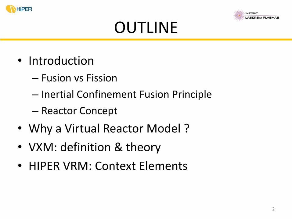
OUTLINE
• Introduction
– Fusion vs Fission
– Inertial Confinement Fusion Principle
– Reactor Concept
• Why a Virtual Reactor Model ?
• VXM: definition & theory
• HIPER VRM: Context Elements
2
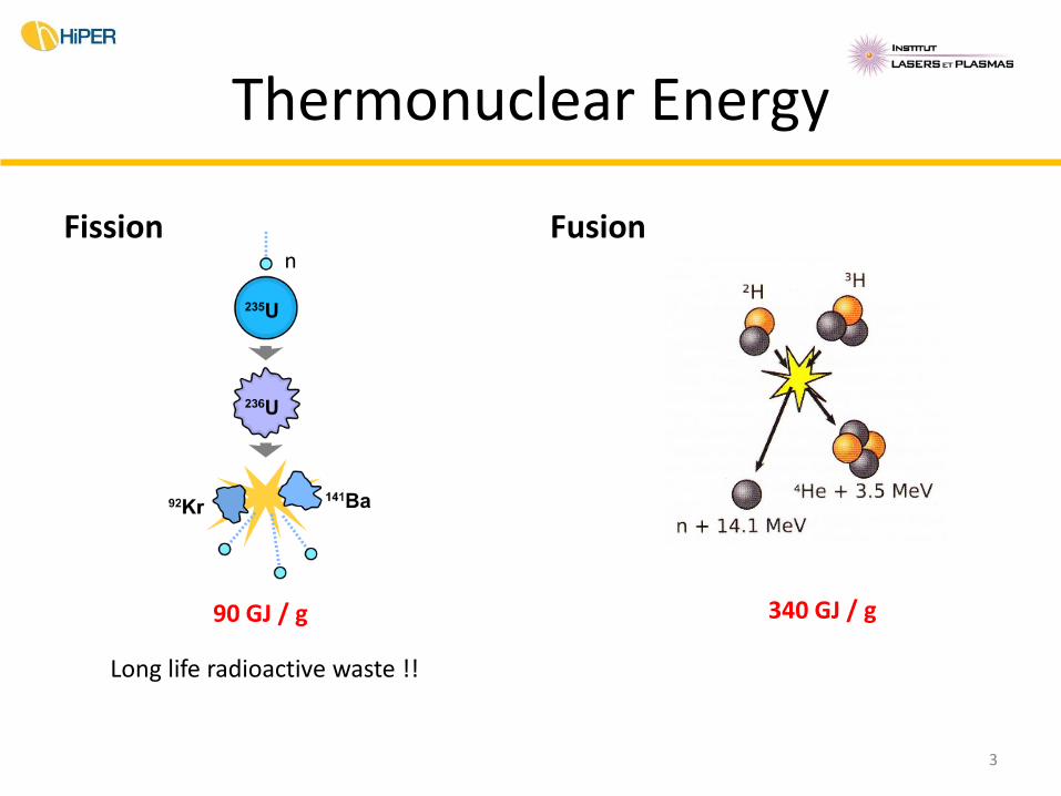
Thermonuclear Energy
Fission Fusion n
Long life radioactive waste !!
340 GJ / g 90 GJ / g
3
Thermonuclear Fusion
• Thermonuclear fusion of light elements
– Easier reaction : D + T 4He (3,5MeV) + n (14,1MeV)
• Lawson Criterion for a positive energy balance:
n (particle density) x t (reaction duration) k
k = 1014 cm-3 at 200 MK
two options :
4
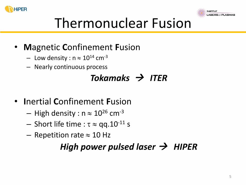
Thermonuclear Fusion
• Magnetic Confinement Fusion – Low density : n 1014 cm-3
– Nearly continuous process
Tokamaks ITER
• Inertial Confinement Fusion – High density : n 1026 cm-3
– Short life time : t qq.10-11 s
– Repetition rate 10 Hz
High power pulsed laser HIPER
5
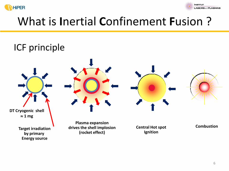
What is Inertial Confinement Fusion ?
ICF principle
Target irradiation by primary
Energy source
Central Hot spot Ignition
Combustion Plasma expansion
drives the shell implosion (rocket effect)
DT Cryogenic shell 1 mg
6
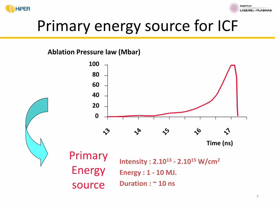
Intensity : 2.1013 - 2.1015 W/cm2
Energy : 1 - 10 MJ.
Duration : ~ 10 ns
0
20
40
60
80
100
Ablation Pressure law (Mbar)
Time (ns)
Primary Energy source
Primary energy source for ICF
7
Energy source for ICF
• Only high power pulsed lasers can provide (today) the required performance. – Laser-matter interaction and implosion experiments have
been widely studied since the sixteen’s
• Two large laser facilities are expected to demonstrate ICF (with a small thermonuclear gain) in the current decade: LMJ in France and NIF in USA.
8
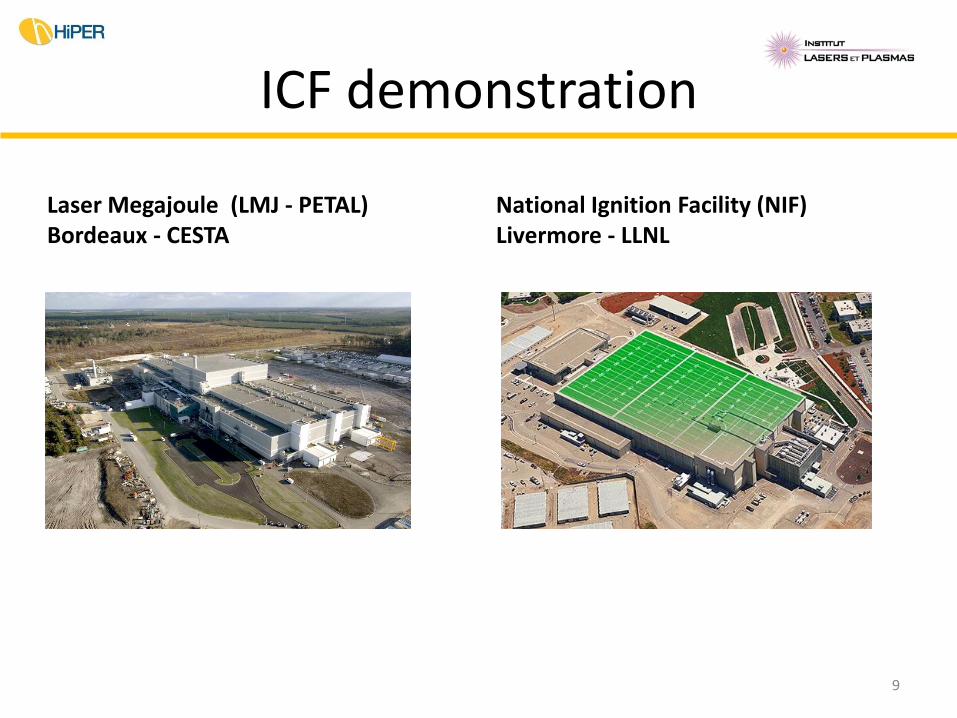
ICF demonstration
Laser Megajoule (LMJ - PETAL) Bordeaux - CESTA
National Ignition Facility (NIF) Livermore - LLNL
9
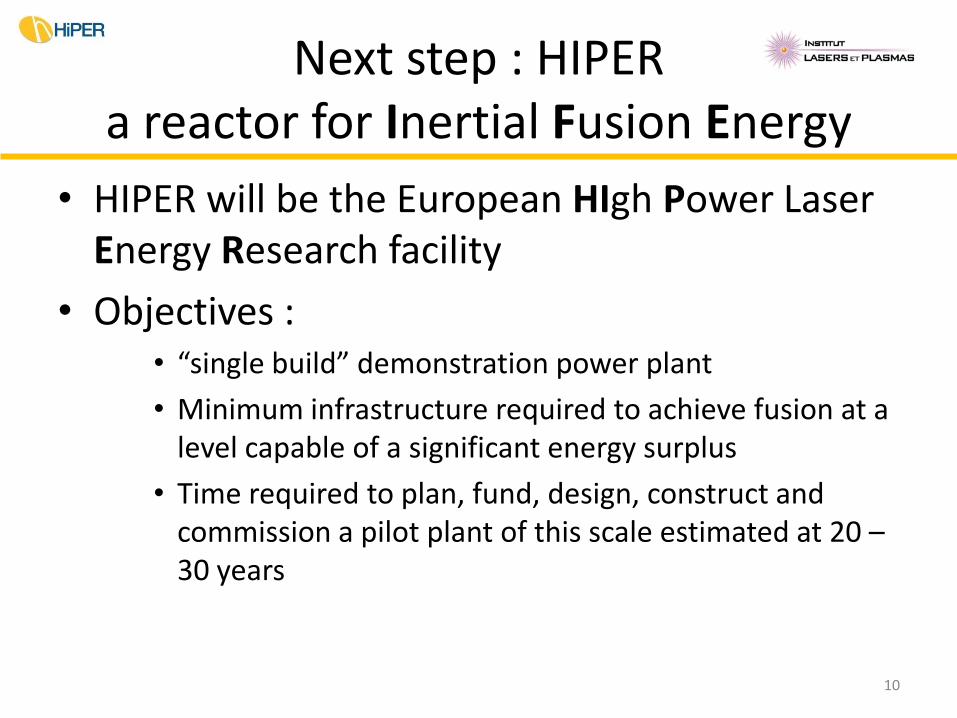
Next step : HIPER a reactor for Inertial Fusion Energy
• HIPER will be the European HIgh Power Laser Energy Research facility
• Objectives : • “single build” demonstration power plant
• Minimum infrastructure required to achieve fusion at a level capable of a significant energy surplus
• Time required to plan, fund, design, construct and commission a pilot plant of this scale estimated at 20 – 30 years
10
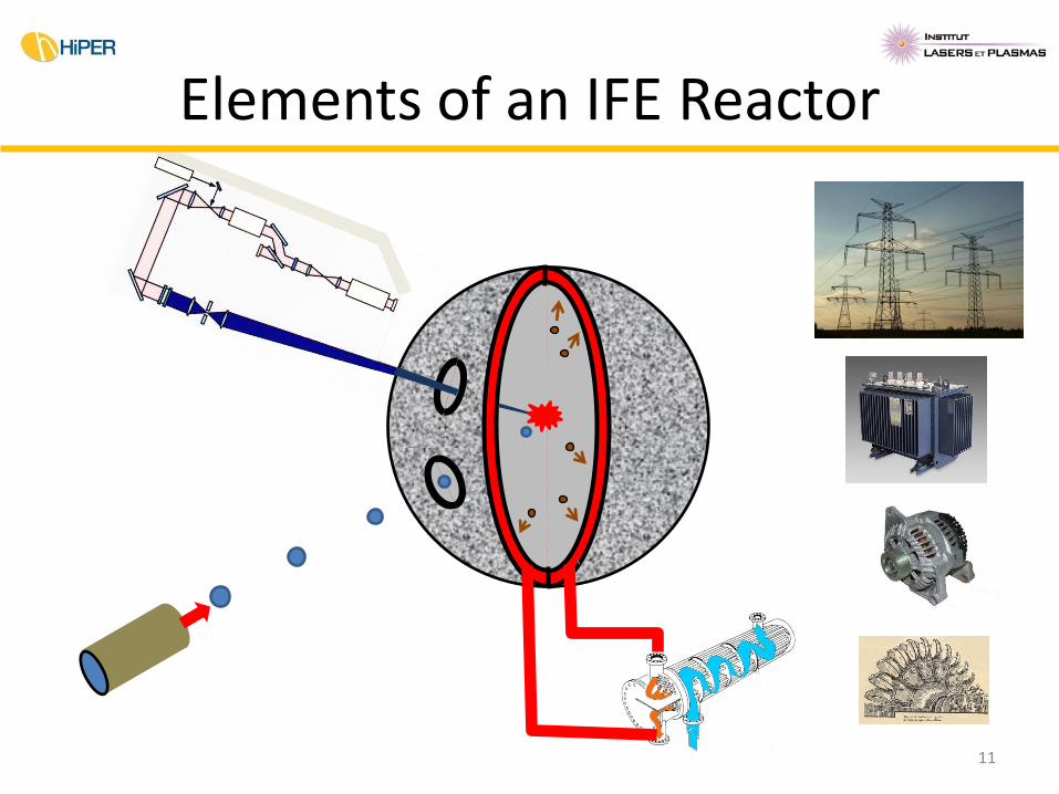
Elements of an IFE Reactor
11
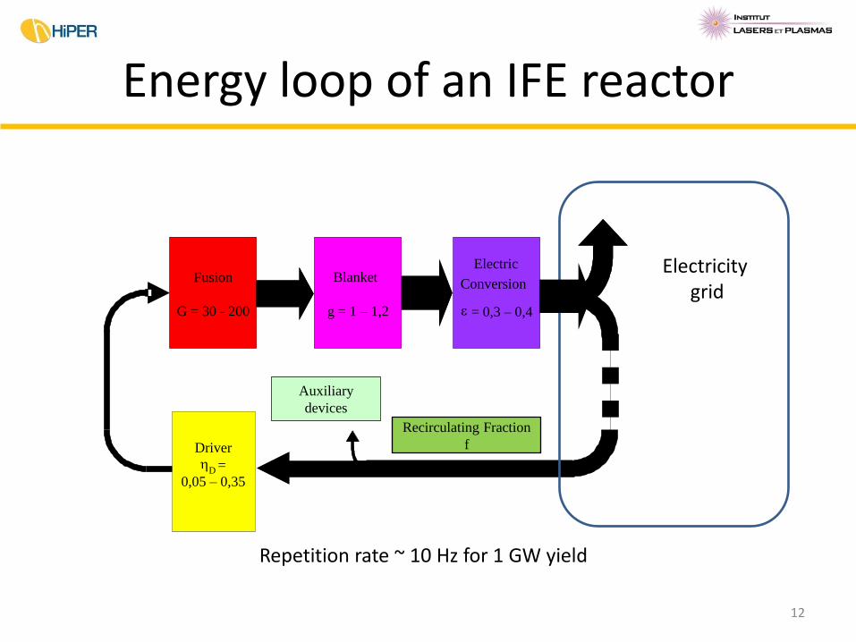
Energy loop of an IFE reactor
Fusion
G = 30 - 200
Conversion
é lectrique e = 0,3 – 0,4
Driver h
D = 0,05 – 0,35
Couverture
g = 1 – 1,2
Fusion
G = 30 - 200
Conversion
Electric
e = 0,3 – 0,4
Driver h
D = 0,05 – 0,35
Auxiliary
devices
Blanket
g = 1 – 1,2
Electricity grid
12
Repetition rate ~ 10 Hz for 1 GW yield
Recirculating Fraction
f
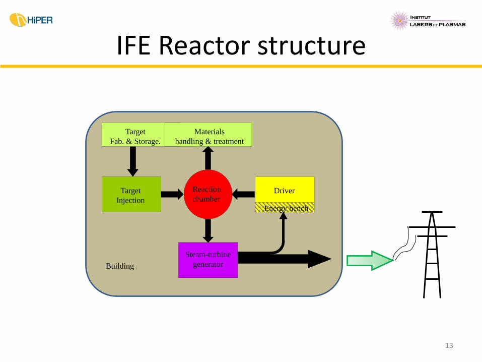
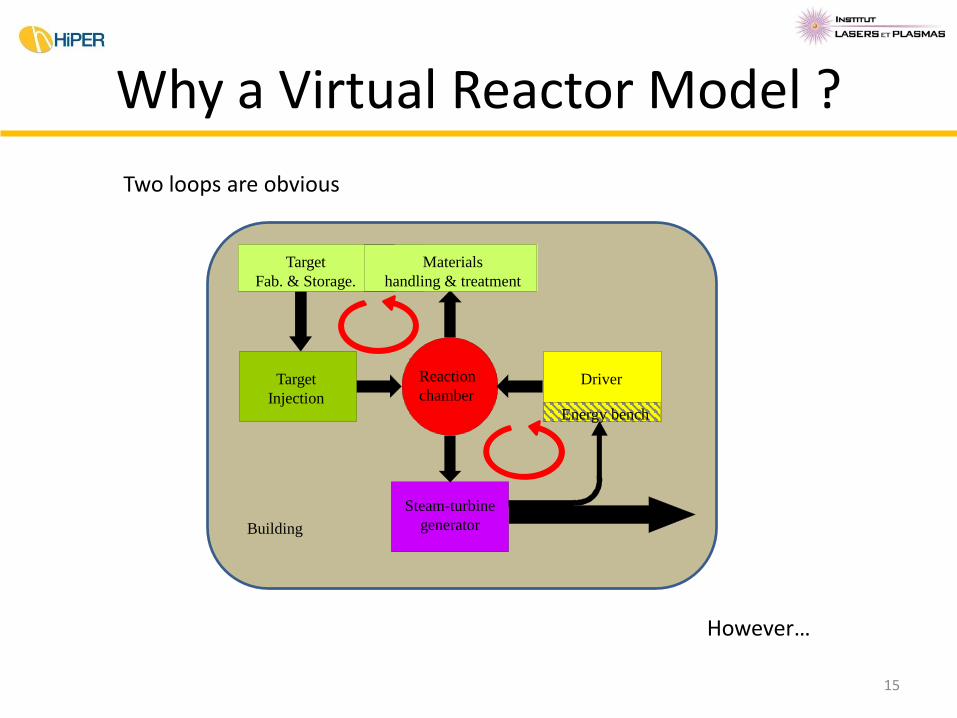
IFE Reactor structure
Driver Target
Injection
Target
Fab. & Storage.
Materials
handling & treatment
Reaction
chamber
Energy bench
Steam-turbine
generator Building
13
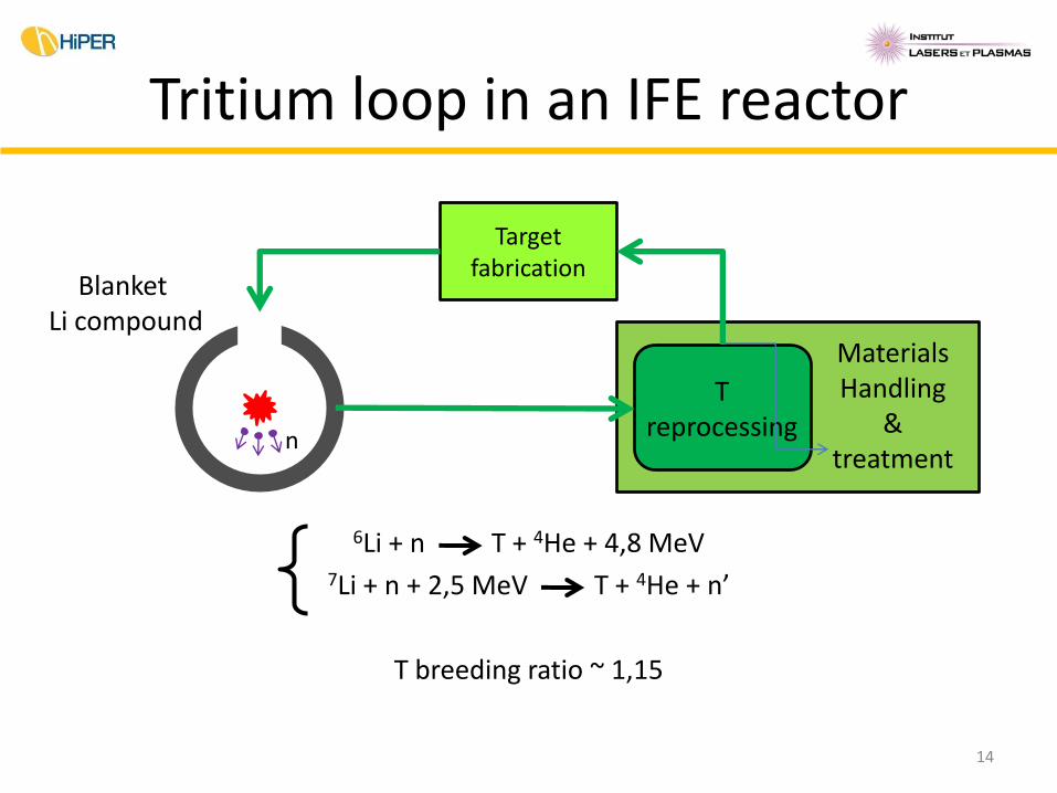
Tritium loop in an IFE reactor
6Li + n T + 4He + 4,8 MeV
7Li + n + 2,5 MeV T + 4He + n’
T breeding ratio ~ 1,15
Target fabrication
Blanket Li compound
Materials Handling
& treatment
T reprocessing n
14
Why a Virtual Reactor Model ?
15
Driver Target
Injection
Target
Fab. & Storage.
Materials
handling & treatment
Reaction
chamber
Energy bench
Steam-turbine
generator Building
Two loops are obvious
However…
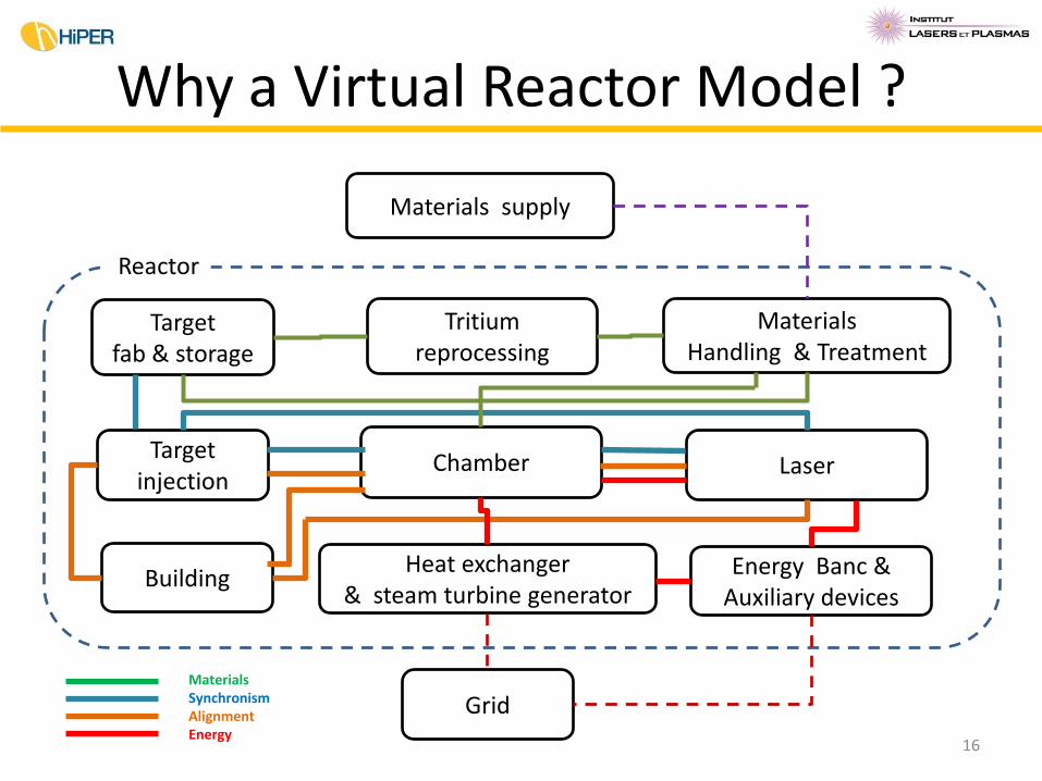
Why a Virtual Reactor Model ?
Materials supply
Target fab & storage
Tritium reprocessing
Materials Handling & Treatment
Target injection
Chamber Laser
Heat exchanger & steam turbine generator
Energy Banc & Auxiliary devices
Building
Grid
Reactor
16
Materials Synchronism Alignment Energy
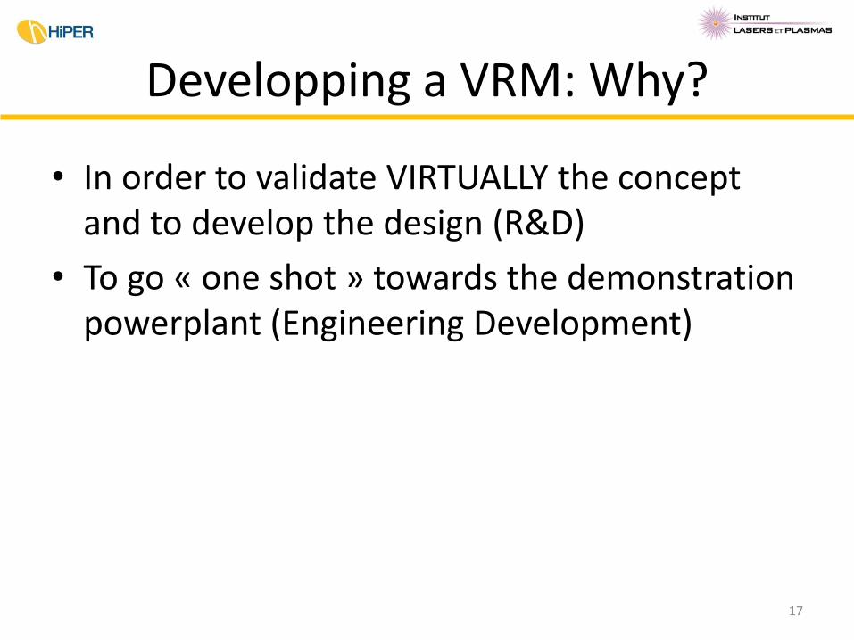
Developping a VRM: Why?
• In order to validate VIRTUALLY the concept and to develop the design (R&D)
• To go « one shot » towards the demonstration powerplant (Engineering Development)
17
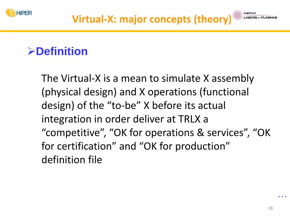
Definition
The Virtual-X is a mean to simulate X assembly (physical design) and X operations (functional design) of the “to-be” X before its actual integration in order deliver at TRLX a “competitive”, “OK for operations & services”, “OK for certification” and “OK for production” definition file
Virtual-X: major concepts (theory)
…
18
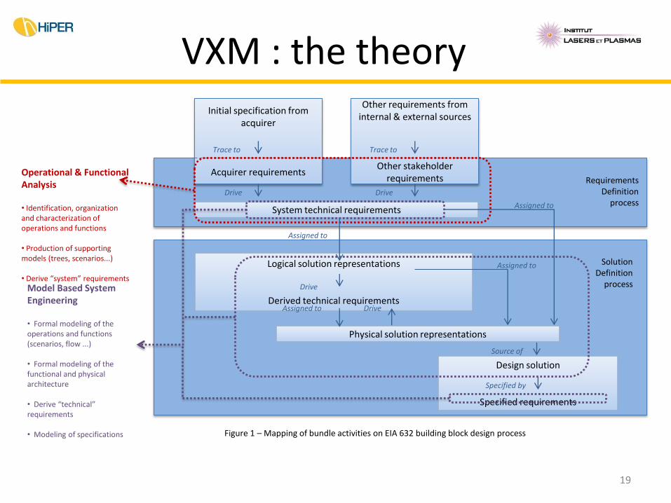
Operational & Functional Analysis • Identification, organization and characterization of operations and functions • Production of supporting models (trees, scenarios...) • Derive “system” requirements
Initial specification from acquirer
Acquirer requirements
Other requirements from internal & external sources
Other stakeholder requirements
System technical requirements
Drive Drive
Requirements Definition
process
Assigned to
Trace to Trace to
Assigned to
Model Based System Engineering • Formal modeling of the operations and functions (scenarios, flow ...) • Formal modeling of the functional and physical architecture • Derive “technical” requirements • Modeling of specifications Figure 1 – Mapping of bundle activities on EIA 632 building block design process
Logical solution representations
Derived technical requirements
Drive
Physical solution representations
Assigned to Drive
Design solution
Specified requirements
Specified by
Source of
Solution Definition
process
Assigned to
VXM : the theory
19
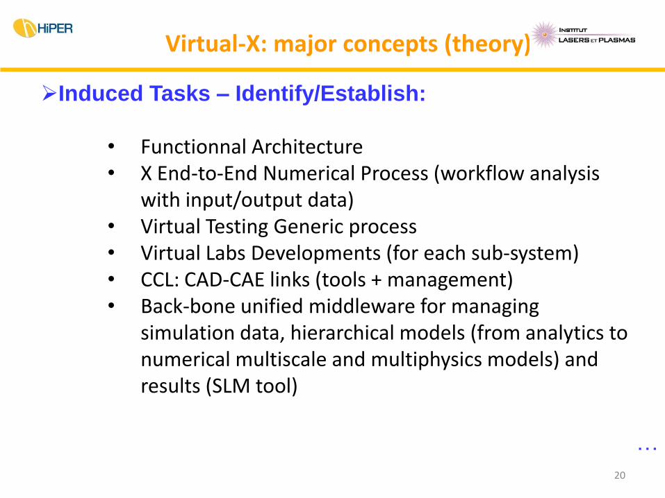
Virtual-X: major concepts (theory)
Induced Tasks – Identify/Establish:
• Functionnal Architecture • X End-to-End Numerical Process (workflow analysis
with input/output data) • Virtual Testing Generic process • Virtual Labs Developments (for each sub-system) • CCL: CAD-CAE links (tools + management) • Back-bone unified middleware for managing
simulation data, hierarchical models (from analytics to numerical multiscale and multiphysics models) and results (SLM tool)
…
20
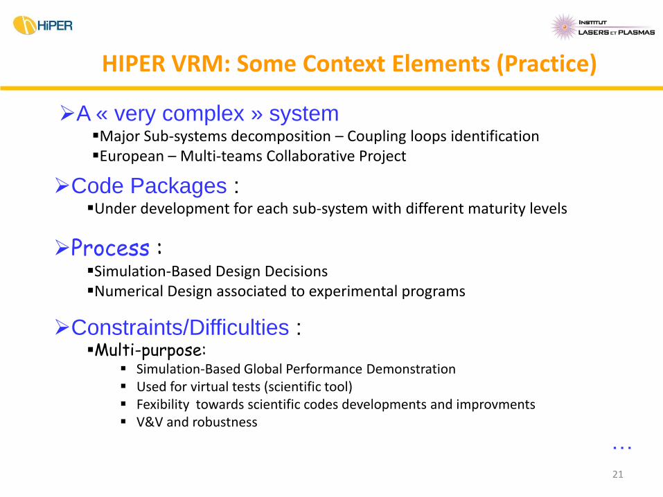
A « very complex » system Major Sub-systems decomposition – Coupling loops identification European – Multi-teams Collaborative Project
HIPER VRM: Some Context Elements (Practice)
Code Packages : Under development for each sub-system with different maturity levels
Process : Simulation-Based Design Decisions Numerical Design associated to experimental programs
Constraints/Difficulties : Multi-purpose:
Simulation-Based Global Performance Demonstration Used for virtual tests (scientific tool) Fexibility towards scientific codes developments and improvments V&V and robustness
…
21
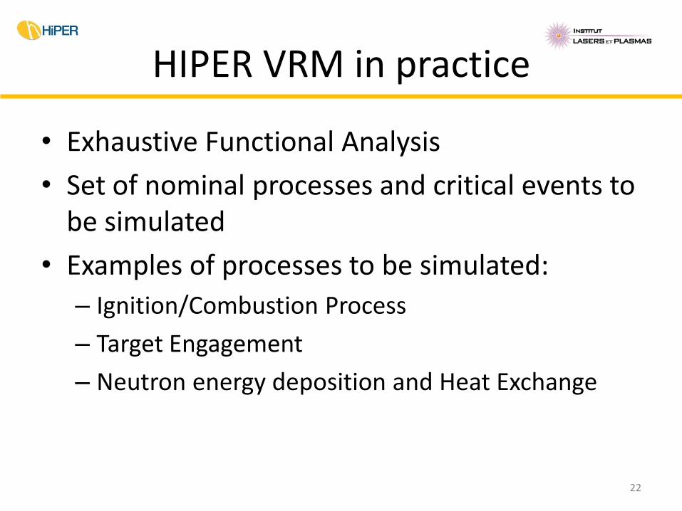
HIPER VRM in practice
• Exhaustive Functional Analysis
• Set of nominal processes and critical events to be simulated
• Examples of processes to be simulated:
– Ignition/Combustion Process
– Target Engagement
– Neutron energy deposition and Heat Exchange
22


![[Phys 6006][Ben Williams][Inertial Confinement Fusion]](https://static.fdocuments.net/doc/165x107/58a7db721a28ab8a7e8b61cb/phys-6006ben-williamsinertial-confinement-fusion.jpg)


