A TYPICAL 74 FRENCH GUNSHIP THE ... - Model Ship...
38
A TYPICAL 74 FRENCH GUNSHIP USING POLYMER CLAY FOR YOUR SHIP MODEL ORNAMENTATION THE MATTHEW PROJECT PART IX: The Upperworks Continued TYPES OF HULL CON- STRUCTION PART III: Plank on Frame Hull SPLICE THE MAIN- BRACE: Is it time for a round of drinks? Volume II, Issue III 2008
Transcript of A TYPICAL 74 FRENCH GUNSHIP THE ... - Model Ship...

A TYPICAL 74 FRENCH
GUNSHIP
USING POLYMER CLAY FOR YOUR
SHIP MODEL ORNAMENTATION
THE MATTHEW PROJECT
PART IX:
The Upperworks Continued
TYPES OF HULL CON-
STRUCTION PART III:
Plank on Frame Hull
SPLICE THE MAIN-
BRACE:
Is it time for a round
of drinks?
Volume II, Issue III 2008

The MSB Journal—Volume II Issue III
www.modelshipbuilder.com 2
The MSB Journal
ISSN 1913-6943
Volume II, Issue III
May 2008
© www.modelshipbuilder.com
All articles published in The MSB Journal are
covered under international copyright laws.
This newsletter may be re-distributed freely as
long as it remains, whole, intact and un-altered.
We also urge you to print a copy for your
workshop or reading area.
Published by
www.modelshipbuilder.com
On the Cover
The 74 French Gunship
How to Contact The MSB Journal
By email: [email protected]
By Snail-Mail
ModelShipBuilder.com
c/o Winston Scoville
5 St. Charles Place RR 5
Clinton, Ontario, N0M 1L0
Canada
Article / Content Contributions
Please submit all article and content
contributions to:
In This Issue
Editors Notes 3
Types of Hull Construction
Part III: Plank-on-Frame 4
MSB Book Nook
The Matthew Project Part IX:
The Upper Works (cont’d) 12
A Typical 74 French Gunship 21
What Ship Is This? 26
Splice The Main Brace 27
Online Discussion Forums 28
Using Polymer Clay for you Model
Ship Ornamentation 29
11
Badges:
Heraldry of Canadian Naval Ships 33
Contributors Pictures 34
Parts of a Sail - Crossword 37
Don’t forget, clicking in the left column
brings you back to this page!

The MSB Journal—Volume II Issue III
www.modelshipbuilder.com 3
Editors Notes
First off, I have to introduce you to the newest crewmember on
our ship. Meet Lila Rose. She was born the beginning of April.
Needless to say there have been many late night watches over
the past month. Of course I guess the joke was on me because
while I sat and pondered what a marvel she was and what the
future held in store for her, she was busy sawing logs!
Through it all I was still able to find time to put this issue to-
gether, though there were times when I wondered if I’d stay
awake long enough to finish what I was working on! :-)
To give you a heads up, over the next month or so I am going to
be changing hosting companies, so you may see some disruptions
at the website and being able to access both the Journal and the site. Any disruption
should only be a short one (if at any) so don’t be alarmed.
We have kind of outgrown our current host and they don’t offer packages in the range
that we need to keep growing. If you need a good reliable web host for a smaller site
(under 500MB), I would have absolutely no problems recommending this one. The price
may be a little steep, but its worth the extra cost (only small). Having been online with
various sites now for about 10 years or so, they are the best I have come across. I only
hope this new host can measure up! :-)
Which brings me to this. In the upcoming year we are going to be expanding the site to
include a members area so that we can bring you a more interactive experience. If you
know anything about PHP, MySQL and CSS, and would like to help build a great website
for all the modelers out there, I’d love to hear from you. Just drop me an email at
[email protected] and I’ll fill you in on the details on what kind of help
we’re looking for. We’re also looking for people who would like to become involved to
help maintain and grow the site once its up and running.
Okay, the Rear Admiral is calling! Enjoy this issue!
Winston Scoville
www.modelshipbuilder.com

The MSB Journal—Volume II Issue III
www.modelshipbuilder.com 4
Types of Hull Construction
Part III:
Plank-on-Frame by Gene Bodnar
Many people think that a scale model
built plank-on-frame (POF) style is the
highest expression of the wood ship mod-
eler’s art. It is the kind of model in which
the builder starts with laying a keel, then
builds the stem and sternpost, and then
frames it as an accurate reproduction of
the prototype ship. From this point, the
exterior planking is trenailed onto each
frame, as precisely as can be accom-
plished, just like in the prototype. Some
POF modeler’s carry it a step further by
building much of its interior, including
deck beams, knees, multiple decks, and
all of its interior fittings, such as ladders,
capstans, and whatever else may be
found below-decks, ending up with a very
impressive model that emulates the real
ship in almost every detail.
This article will attempt to explain some
of the mystery involved in building a POF
model. Actually, this type of model is no
more difficult to build than a plank-on-
bulkhead model; it just has more pieces to
make.
This article also assumes that you are
familiar with lofting your own frames,
meaning that you are capable of interpret-
ing the lines shown on a set of plans and
that you can draw frames from the given
lines. If you are not familiar with this proc-
ess, a few good sources of such informa-
tion are given at the end of this article.
Laying the Keel
As with the real ship, we begin building
the POF model by laying the keel. If the
model is built on a large scale, it may be
made of two or more pieces of straight
wood jointed and glued together on a per-
fectly flat surface. It should be made a few
inches longer at both ends than the length
shown on the plans so that it will be held in
a jig, which will be explained later.
Add the Sternpost
The sternpost is the piece of wood
mounted at the aftermost end of the keel
and is the place for holding the rudder.
From the plans, determine the length of
the sternpost, and use a piece the same
thickness as the keel. It is a good idea to
drill a couple of small holes up from the
bottom of the keel into the sternpost, and
then dowel them together.
Add the Stem
From the plans, lay out the shape of the
stem (or cutwater), which is located at the
front of the vessel, usually rising in a
curved shape just below the projection of
the bowsprit. Cut out this piece of wood,
which is the same thickness as the keel,
and then glue and dowel it in place.
Build the Deadwood
The deadwood appears at the bow and
stern area of the keel assembly. It pro-

The MSB Journal—Volume II Issue III
www.modelshipbuilder.com 5
vides an extension of the keel to which
other timbers, particularly
planking, is attached. It should be made of
several pieces of wood the same thickness
as the keel and fitted snugly together and
glued in place. Make a few scarf joints in
the pieces of wood to simulate the con-
struction found in the actual ship. It is rec-
ommended here, too, that these pieces be
doweled in
place to the stem and sternpost and to
each other to give the entire assembly a lot
of strength.
Cut the Rabbet
The exterior planking will be resting in
the keel, stem, sternpost, and deadwood
areas at varying angles. The first strake of
planking, called the garboard strake, will fit
directly into a groove cut into these areas.
The
object of cutting the rabbet is to allow the
garboard strake to fit snugly into this
groove. The width of the rabbet that is cut
will depend on the thickness of the plank-
ing material and also on the angles at
which the planking intersects the rabbet. A
bearding line is usually found on most
plans; this line represents the innermost
extension of the rabbet. Note that at the
stern near the keel, the bearding line is
quite wide and rounded. This distance
represents the area upon which the exte-
rior planking will rest, tapering smoothly
toward the sternpost. Using a steel ruler
and an X-Acto knife, remove all the un-
wanted material, remembering to adjust
the angle of the cut as you approach either
end of the model. Use miniature files to
clean out the rabbet as you cut.
Mark the Frame Locations
One method of determining where to
place your frames is called “room-and-
space.” There are other methods, but this
is the one described here for illustration
purposes. In the room-and-space method,
it is assume that the width of one frame is
equal to the distance between two frames.
For example, if your frame width will be
¼”, then the vacant space on either side of
this frame will also be ¼”. In other words,
there will be a frame, a ¼-inch space, a
frame, a ¼-inch space, and so forth.
Examine the profile view of the ship on
your plans. Note the section
lines already drawn on the plans will corre-
spond to the location of bulkheads, espe-
cially if you are using plans designed for a
POB model. Note also that there is a
“center” section line located about amid-
ships in the plan. Usually, the plans can be
easily converted to POF plans by adding
additional “bulkhead” lines. Measure the
distance between these section
lines to determine how many additional
lines should be drawn to make each of
them equidistant from each other, starting
from the center section line. For the pur-
poses of illustration, it is assumed that ¼”
intervals will work. Mark your additional
section lines all across your plans, making
all of them
parallel to each other and perpendicular to
the load waterline. It helps to color in the
frames will a colored pencil for distinguish
them from the spaces. Then transfer these
same lines precisely in the same locations
to your keel assembly, again distinguishing
the frame locations from the spaces.
Cut Out Frame Spaces on Keel
The full frames (as opposed to cant
frames) will be located between the two
deadwood areas of the keel. The full
frames will rest in notches cut out for each
of them, and they will be perfectly perpen-
dicular to the keel assembly when placed in
the notches. Now cut out these notches to
the depth you have determined in lofting
the frames, which will end just above your
rabbet.

The MSB Journal—Volume II Issue III
www.modelshipbuilder.com 6
Make the Keelson
The keelson is the internal keel that is mounted immediately above the main keel on
the upper edges of the bases of the frames. It secures all the full frames in place and also
provides extra strength to the main keel.
The Keel Assembly Finished
So far, the keep assembly looks like this:
Build a Framing Jig
To hold the keel assembly and the frames it is necessary to build a compound jig. The
base of the jig, sometimes called the clamping jig, holds the keel assembly in place, ensur-
ing that it cannot move in any direction. It consists of a perfectly flat board a little longer
than the length of the keel assembly. Angle irons or other L-shaped material is attached
to the board at the stem and stern, and small piece of wood are placed along the edge of
the keel to prevent the possibility of the keel warping out of shape. It is a good idea to
mark the location of all frames on the base of this jig. This part of the jig is shown in Fig.
2.
Fig.1
Fig.2

The MSB Journal—Volume II Issue III
www.modelshipbuilder.com 7
A second part of the same jig is called the alignment jig. It consists of a piece of plywood
or Masonite cut out to the exact shape of the hull at the load waterline, with notches cut
out for the precise location of every frame at the same load waterline. It is secured to the
clamping jig below it with blocks of wood spaced so that it meets the load waterline pre-
cisely. Some builders use nuts and bolts for the spacing distance. The frame markings of
this part of the jig should be directly aligned above the frame markings of the clamping jig.
The final framing jig is shown below.
Make the Frames
As mentioned earlier, it is assumed that you have lofted all the required frames, and
that you are now ready to build them.
There are several ways to build frames, some more sophisticated than others. Some
modelers will cut them from a solid piece of plywood; others will make them from several
pieces of wood glued and doweled together, as shown below, with the grain of each piece
of wood following the curve of the frame (see Fig. 4). Still others model them out of dou-
ble layers of wood along with chock blocks between joints, just as they did in real ships.
Fig.3
Fig.4

The MSB Journal—Volume II Issue III
www.modelshipbuilder.com 8
If you have lofted your frames properly, you have also determined the bevel required
for each frame. Now is the time to form the bevel either by trimming with knives or by
sanding it. It is critical that the bevel be made precisely. Just like in plank-on-bulkhead
models, the bevel is the resting place for the exterior planking.
Temporarily install each frame in its location on your framing jig, aligning it perfectly
within all the notches in your jig. Using a long length of
your exterior planking material, place it along several or you frames to check your bevel
just as you did for POB models.
The cant frames at the bow and stern deadwood areas are different from the rest in
that they are made in two pieces, with one half attached to each side of the deadwood at
the places you’ve marked. They, too, require a bevel; in fact, the bevels at these points
will be more extreme than at other locations, so be careful that they are accurate.
Install the Keelson
Once all the center frames are completed – those frames not situated on deadwood –
you may install the keelson, which rests directly atop those frames. It is recommended
that you glue and dowel the keelson onto each frame.
A Great Example of a POF in Progress
If you have followed these instructions for building a POF, your model should look simi-
lar to the outstanding example shown below:
What’s Next?
After you have completed framing your POF model, the remainder of the build is han-
dled just like another other model. The exterior of the hull is now planked. A very big ad-
vantage of the POF model is that the planking will be much more accurate that any other
method used, because the frames will be spaced much closer together than a POB hull,
thus eliminating the need for a second layer of planking material. It is unlikely that there
will be bulges or inaccuracies you commonly find in POB models. Each plank, of course,
can be trenailed precisely to each frame, just as the real ship was
Fig.5 Fig.6

The MSB Journal—Volume II Issue III
www.modelshipbuilder.com 9
trenailed, and they have a solid backing to connect to as well. Your planking will be fin-
ished in the exact same way as the real ship.
Another big advantage to building the POF hull is that you can build as much of the in-
terior of the hull as you like. You are no longer hindered from doing so, because the entire
interior is still wide open. You can add other decks, if you like. You are only limited by
details you see on your plans. Actually, if you do further research, you may be able to
build the entire interior exactly like the original ship. If you do this, you may also want to
leave several of the exterior planks off the ship to show your handiwork. There’s nothing
like the feeling you experience when you successfully complete a POF model with your own
hands.
The Hahn Method of POF
An important addendum to this style of hull construction is the Hahn method, named
after Harold Hahn, a prominent shipmodeler who developed the method. Briefly, his
method lengthens and extends all frames to the same plane such that the tops edges of all
frames are parallel to the keel. He then constructs a framing jig that connects all the top
edges of these frames so that the frames correspond to the shape of the load waterline.
Then, the frame is inverted so that it now becomes the base of the jig, and each frame is
inserted into the base upside down and attached to the keel, which is now located at the
top.
The biggest advantage of the Hahn method of POF construction is that it guarantees
that the shape of hull will be perfectly symmetrical at all points. It also makes the model
much easier to plank, because the model is always upside down as the planking pro-
gresses. A couple of pictures of an outstanding model in progress will serve to illustrate
the process:
A disadvantage of the Hahn method is the fact that there is a considerable wastage of
wood. After all framing and planking is completed, the frames are sawn off at the rail
level, which means the portions of the wood frames between the rail and the edge of the
jig are wasted material that is simply scrapped because it’s not much good for anything
else.
Fig.7 Fig.8
The MSB Journal—Volume II Issue III
www.modelshipbuilder.com 10
The Next Article
The next part to this series of articles will briefly cover Admiralty models.
Further Reading
For further information on reading and interpreting plans, lofting your own plans, and
building plank-on-frame models, the following books are highly recommended:
1. Plank-on-Frame Models, Volume 1 by Harold Underhill.
2. Ship Modeling from Scratch by Edwin B. Leaf.
3. Historic Ship Models by Wolfram zu Mondfeld
Credits
Fig. 1 -- from Ship Modeling from Scratch by Edwin B. Leaf, p. 51. Fig. 2 -- from Ship Modeling from Scratch by Edwin B. Leaf, p. 55. Figs. 3 & 4 -- courtesy of the author. Figs. 5 & 6 – Brigantine Leon, courtesy of Keith Harrison of www.modelshipworld.com Figs. 7 & 8 – Frigate Confederacy, courtesy of Eric Tilley of www.modelshipworld.com
Books on Modeling
Get them today from The MSB Store
Along with many other great publications

The MSB Journal—Volume II Issue III
www.modelshipbuilder.com 11
Captain Cook’s
Endeavour (Revised Edition)
By Karl Marquardt
Price: $36.95
Eligible for Free Shipping
on orders over $25.00
at our Amazon Book Store
MSB Book Nook
The Endeavour, made eternally famous by Captain Cook's first voyage in her in 1768-71, was origi-
nally the collier Earl of Pembroke and was chosen by Cook for his voyage because of her strong con-
struction. She was purchased by the Royal Navy at Whitby and then converted to an exploration ship
at Deptford. After her voyage she was sold out of service in 1775, and finally condemned sometime
in the 1790s.
This revised edition features accurate, visually exciting and totally comprehensive drawings. In addi-
tion to these, a colour representation of Endeavour on the jacket provides a useful painting guide, on
the back of which is a beautifully folded large scale plan of the ship.
The 'Anatomy of the Ship' series aims to provide the finest documentation of individual ships and
ship types ever published. What makes the series unique is a complete set of superbly executed line
drawings, both the conventional type of plan as well as explanatory views, with fully descriptive keys.
These are supported by technical details and a record of the ship's service history.
Karl Heinz Marquardt is an internationally known ship modeller and has spent a lifetime researching
the era of the sailing ship. He is an accomplished draughtsmen and has illustrated a number of highly
praised maritime books.
With over 200 perspective and 3-view drawings, accompanied by in-depth descriptive keys.
Get your Copy Here
In the Anatomy of a Ship Section

The MSB Journal—Volume II Issue III
www.modelshipbuilder.com 12
The Matthew Project Part IX
Bulwark Planking
Planking the bulwarks begins with the
scuppers shown on the photo of the Mat-
thew. The Matthew built in
England simply left off the first plank above
the wales at midship. We will begin by
marking out at plank at every stanchion
and dividing the width of the plank in half.
Using a drum sander each scupper is
sanded out leaving nice rounded corners.

The MSB Journal—Volume II Issue III
www.modelshipbuilder.com 13
Once all the scuppers are sanded into the
plank it is positioned on the hull at mid ship
and the bulkwards are planked to the cap
rail.
With the planking complete to the cap rail
we will stop at this point and move on to
laying out the main deck. There are various
molding pieces, which fit at the quarter and
forecastle where the deck meets the side of
the hull. In order to install these decks the
main deck has to be laid down first.
Looking at the deck layout we will need to
install a few items before we can start lay-
ing deck planking. Starting at the bow the
first pieces will be the platform the capstan
sits on. The deck is not level, it has a sheer
from the bow to the stern, if the capstan
platform were laid on the deck it would
have a slant as shown in the first drawing.
In the second drawing the capstan platform
is wedged shaped allowing the capstan to
sit vertical. On the model a wedged
shaped platform is used. Exactly how the
platform is made will be up to you as the
builder. In the photo it appears the plat-
form is higher in the middle then tapers to
the front and back. This platform would

The MSB Journal—Volume II Issue III
www.modelshipbuilder.com 14
have been made of two or three heavy tim-
bers rather than one piece.
It’s a simple job to make the platform. Cut
a piece from the ¼ thick sheet material to
the size indicated on the plans. Cut a
grove along the two sides to the correct
depth then clamp the piece in a vice. Pro-
ceed to sand down the surface until its
even with the groves on either side.
Building the rest of the capstan began with
turning the spindle to the measurements
on the plans. Two circles were cut from
sheet stock and black paper was glued
around the edges to
simulate the band-
ing. Cutting the cir-
cles for the spindle
and the head peaces
is a simple job of
finding an exact size
washer and using it
as a guide. Using a
double sided tape stick the washer to a
piece of wood. With a single edge razor
blade continue to nip away the wood until
you have a nice circle.

The MSB Journal—Volume II Issue III
www.modelshipbuilder.com 15
The three head piece you just cut now
have to be split for the bars. Using a piece
of two sided tape stick the end of a bar to
the center of the circle piece. With a sharp
razor blade cut on both sides of the bar
producing two semi circle pieces. Do this
with all three circle pieces. Mark out the
center of the spindle circle and place the
bar in the center of the circle. Glue the two
semi circles on both sides of the bar. Be-
fore the glue sets remove the bar so it
does not end up getting glued to the cir-
cles. Do the same thing with all three cir-
cles being sure you rotate the location of
each bar. The final piece is the drum cap.
With everything glued in place sand the
drum smooth.
You can glue the capstan together but at
this time do not glue it to its base. If you
glue the capstan to its base it will be in the
way of planking the deck.

The MSB Journal—Volume II Issue III
www.modelshipbuilder.com 16
Looking at the capstan on the Matthew
there are thin boards called whelps at-
tached around the spindle. You can either
scribe lines in the spindle and cut a small
notch at the base or add the thin boards
around the spindle.
The next item is a hatch, which will take a
bit more work to create than the simple
platform. Before building the hatch coam-
ing, lets first examine a real hatch and see
how they are built.
In this photo the view is from inside of the
hold looking up through a hatch. A com-
mon error model builders will make is place
the hatch coamings on top of the deck
planking. In actual construction the coam-
ings rest on the deck beams and carlings
with the ends of the deck planking butting
against the sides of the coamings.
The next photo is standing on deck looking
at the hatch. The white arrow points to the
coaming, the yellow arrow is the deck
beam and the blue arrow is the carling.
At the corners coamings have a lap joint
which is fastened with a long spike which
goes down through both coamings and into
the beam below. The white arrow points to
the head of this spike. The height of the
coamings will vary from ship to ship and
from builder to builder. An average is 8 to
14 inches.
The Matthew hatch has a separate piece on
the top edge forming an inset for the hatch
covers. There is a piece fastened to the
side of the coaming with a slit cut in one

The MSB Journal—Volume II Issue III
www.modelshipbuilder.com 17
end where a board is slid through to hold
the hatch cover boards in place.
Hatches on the Matthew appear to be
about 18 to 24 inches, which seems to be a
little high for a coaming, on the model the
coamings are 12 inches. There is no right
or wrong way, so if you want to make your
coamings 12 inches or 20 inches the choice
is up to you. If you do decide to go with a
higher coaming you will not be able to
overlap the corners. Corners on the higher
coamings will either have to fit at a 45-
degree angle or butt together.
The following steps are using a piece of ¼
x 1/8 inch material. Each corner is cut
with an overlapping joint and then two
sides are glued using a square block cor-
ner . After you have a set of two sides

The MSB Journal—Volume II Issue III
www.modelshipbuilder.com 18
glued up, glue the two pieces together to
form a complete coaming. Once all the
sides are glued together place a 1/16
square frame around the top to form a
ledged for the hatch cover boards.
Carlings were added to between the bulk-
heads for the hatch coamings to sit on and
add a surface along the hatch for the
planking.
Next in line are the mast partners. First the
center profile piece is cut away so the mast
can drop below the deck. A piece of dowel
is positioned and two side supports are
glued in place. Making the mast partner is
a simple job of cutting a square to the size
indicated on the plans and cutting a hole in
its center for the mast. Position the part-
ner so the mast hole is tight to the forward
bulkhead and not centered between the
bulkheads.

The MSB Journal—Volume II Issue III
www.modelshipbuilder.com 19
Three pin rails are needed of slightly different sizes so we begin by cutting to length six
pieces of square stock and clamping them together. Draw a line for the center of the
curved section. The series of photos show how the rail is assembled and glued to the face
of the bulkhead.

The MSB Journal—Volume II Issue III
www.modelshipbuilder.com 20
At the break of the quarter deck the Mat-
thew leaves the middle section open with a
cabin on either side. It was a common
practice to completely close off the break of
the quarter deck with a bulkhead. As a
model shipwright you can choose either way
and either would be correct. My thought
was to close off the end of the quarter deck
with a bulkhead to make a dry cabin area.
This was an exploration ship and was in-
tended to sail on the open ocean. A dry
cabin would be quite welcome by the crew.
Bulkheads sat on what was called a sill. This
sill had the same purpose of coamings
around hatches. They sealed the hatch or in
this case the bulkhead from water seeping
in. In the B&W photo you can see the sill
being pointed to by the blue arrows. If you
intend on building a bulkhead start with
adding a landing for the main deck plank-
ing, This was done by gluing two pieces of
wood to the outer face of the bulkhead
shown by the white arrow. A sill sits directly
on the deck beam and the deck planking
butts against the side of the sill and
caulked between the decking and sill. Look-
ing at the photo you can see how the use of
a sill would prevent water from getting into
the cabin area, as apposed to the bulkhead
sitting directly on the deck.
There are a few other items to add to the deck but they will be added after the planking is
finished.
The MSB Journal—Volume II Issue III
www.modelshipbuilder.com 21
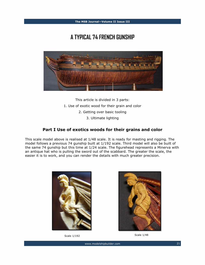
A TYPICAL 74 FRENCH GUNSHIP
This article is divided in 3 parts:
1. Use of exotic wood for their grain and color
2. Getting over basic tooling
3. Ultimate lighting
Part I Use of exotics woods for their grains and color
This scale model above is realised at 1/48 scale. It is ready for masting and rigging. The
model follows a previous 74 gunship built at 1/192 scale. Third model will also be built of
the same 74 gunship but this time at 1/24 scale. The figurehead represents a Minerva with
an antique hat who is pulling the sword out of the scabbard. The greater the scale, the
easier it is to work, and you can render the details with much greater precision.
Scale 1/192 Scale 1/48

The MSB Journal—Volume II Issue III
www.modelshipbuilder.com 22
There will be three 74 gunship built, however, different woods and different techniques will
be used for their construction. The references used to build this model ship are 4 volumes
of Jean Boudriot. These volumes are not a practicum, but do explains with great detail the
construction of the 74 gunship. When you have so much information about the same ship,
you can produce a high quality model many details and you can learn so much about the
construction and the history of the French naval construction.
I began this model 1½ year ago. I like to try different wood color combinations. Matching
colors is not easy to get harmonious results. On the other end, I could not do a mono-
chrome model entirely realised in one kind of wood only. I do not want to use paint or dye
on the wood. For the finishing, Danish teck oil is applied. The use of exotics woods and oil
helps to give an overall appearance a look of a model ship built 100 years ago... and for
my taste, this is the look I am trying to achieve.
For the rigging, I have 1 kg roll of linen. With this roll I can turn all the necessary rigging I
need. To increase the diameter of a line, I simply add more linen threads on the rope ma-
chine.
To get the desired color effect on the standing rigging, I use a dye powder called
“Acajoutine”. I mix brown and red dyes together to obtain a brown reddish color to imitate
the tar used in that period.
Although pearwood is a fruit wood, it could be considered one of the less dense of the ex-
otics woods. It is exceptionally easy to work for this category of wood. Boxwood works
Example showing the composition of a cotton rope

The MSB Journal—Volume II Issue III
www.modelshipbuilder.com 23
great for sculpture and smalls turnings. Eb-
ony is excellent for the black parts, but it is
not easy to bend when it is too thick, it
must be laminated. Bubinga, when care-
fully chosen, works great for the framing, it
looks like wood grain at the good scale. It
also gives an older look to the scale model.
Bocote imitates old oak at this scale. For
the mast, goncalo alves gives a nice effect.
I have also tried bloodwood for the red
parts but it is hard to work.
Part II Getting over basic tooling
In a first period, I built model ships for 15
years. I believe that it is a normal progres-
sion over the years to upgrade tooling
when you want to save time and to work in
a better and easier way.
At the beginning, an Xacto knife was used.
One day, I discovered scalpel blade. This
blade is thinner than Xacto blade, it can
break easily but it cuts so much better.
When you working with a scalpel handle for
a long period of time, you can get cramps
in your hands. So, the next step was to
buy another scalpel handle covered with
acrylic which makes it much easier to work
with.
Here is another example with sanding. At
first, I bought a disk and belt bench
sander. When you place a block of wood on
the table, you can sand it perpendicular to
the table. Then, one day I wanted to do the
same thing with a small steel block. You
can achieve it, but it takes a long to do. If
you apply too much pressure, the block will
not have perpendiculars sides. The next
step is to buy a better sander, or even bet-
ter, you can build one as I did. The knife
belt sander works very fast and can be
very precise for wood and as well for
metal.
Let’s know see the use of a lathe. Watch-
maker’s lathe is not made for us. A mini
lathe is more appropriate and versatile.
With this kind of lathe, you can turn a pass
of .001” at a time. Turning a big part with
this lathe can be a very long and tedious
task. The next step is a tool room lathe.
This lathe is not expensive as you may
think at first. I bought it used and I paid
$2000 about 5 years ago. This lathe can
easily take .01” by pass. This means, you
can produce a piece 10 times faster.

The MSB Journal—Volume II Issue III
www.modelshipbuilder.com 24
Metal lathe tools accessories can be very
expensive. As an example, if you buy a 3
jaws chuck with a precision of .001”, you
could pay $150 depending of the size. If
you buy one with a precision of .0001”, you
would have to add a 0 to the price. Again,
another option is to build the tools you
need.
When I had badly fractured my right index
finger, I had stopped model ship building
for a while. I did not have enough dexterity
to make knots for the rigging. Instead I
changed to tools building. During this sec-
ond period, I wanted to be able to build
anything I wanted. To have a lathe was the
first goal; to equip it is the second, be-
cause there is always a missing tool to
build a more complex tool. For the metal, 3
categories of tools and accessories are
needed: lathe, milling and grinding. I went
through that spiral for a period of 10 years.
1½ year ago, I did not have any more tools
to build. I now had a options to do the
work I wanted. I like to use my hands and
my brain to create something so, I turned
once again to model ship building.
Many tools we use already exist in other
professions. Dentistry can offer us a wide
variety of dental burs perfectly suited for
our needs. The jewellery world is a very
helpful world. It is nice to say: “If you buy
a tool, buy a good one”. This is not as easy
as it is sounds. When we begin to build
model ships, we are not aware of the wide
range of tool availability on the market. So
we buy the tool we know at this moment
and we use it as long as we
do not need any better.
The first rotary tool I bought
was a Dremel. I had many
years of satisfaction with it.
But this tool is heavy, not
very strong and is very noisy
to use. Foredoom shaft was
the next step with different
heads through the times. The
Foredom’s shaft decreases the
dexterity of the user. To elimi-
nate this shaft, we can go one
step further; Gesswein electric
rotary handpiece. The speed
turns from 0
to 50,000
turns per
minute. The
motor is very
quiet. The
precision and
the dexterity
offered by
this tool are
outstanding.
One last
point, when I
work, there
is no other
tool on the
table than
those I need
at this mo-
ment. I want
to have as
less possible tools on the table. The cleaner
is the place, the easier it is to work, and
the easier it is to find the tool when you
need it. The little tools that I use regularly
are placed in the tray system near by the
table.

The MSB Journal—Volume II Issue III
www.modelshipbuilder.com 25
Part III Ultimate Lighting
Lighting is an under-estimated subject. To clearly see an object, 2 things must be consid-
ered; accurate vision and lighting. When I need to work on small objects, I use a head
magnifier with interchangeable lens. It can be use with or without eye glasses. For the
sculptures and smalls detailed works, I use a surgical loupe. If I need to check a very small
detail, or if I want to check a first part of a series, I use a gemmology microscope.
A well adapted lighting greatly facilitates the work and reduces the ocular tiredness. Basic
lighting is done with neon fixtures on the ceiling. Incandescent light must be avoided. A
good neon quality produces a good color rendition. For the close range work, a Dazor jew-
eller’s bench top light with 3 neons is the best. Finally, for the small details, I bought sur-
gery lights on eBay. With this type of lamp, there will be no hidden details and the color
rendition will be very close to the reality. Dentist’s lights are not as powerful. Their color
rendition is much less accurate. I do not use anymore halogen lamp because it radiates too
much heat and color rendition is too yellow. These types of lamps are fixed to the ceiling
and it is possible to adjust it in almost any position. From all these previous lamps, if I had
only one to choose, I would pick the one I use the most often; the Dazor’s jewellery lamp.
You’ll soon be able to see more pictures of these models at the Model Ship Builder website in the
model builders section.

The MSB Journal—Volume II Issue III
www.modelshipbuilder.com 26
HMS Ark Royal
This is the fifth vessel to bear the
proud name. Ark Royal was built
by Swan Hunters Ship Builders'
yard at Wallsend in December
1978 and launched by Her Maj-
esty Queen Elizabeth the Queen
Mother. HMS Ark Royal was ac-
cepted into service on 1 July
1985.
Last Issue
What Ship Is This?

The MSB Journal—Volume II Issue III
www.modelshipbuilder.com 27
SPLICE THE MAINBRACE! by Gene Bodnar
In pirate movies, in books, in bars, in today’s popular culture, you hear it frequently:
“Splice the mainbrace!” It’s time for a round of drinks. The term originates, of course,
from the days of the wooden sailing ships. It was an order to perform a difficult and dan-
gerous repair job aboard a sailing warship, frequently right during the engagement that
caused its loss.
As every ship modeler knows, braces are the lines that control the angle of the yards.
The mainbrace, especially on a first-rater, was the heaviest rope of the running rigging, up
to five inches in diameter. It was common practice during a naval battle to aim for the
mainbrace; if it was shot away, the ship would stay
on the same tack, could not be steered at all, and
became a much easier target of destruction for the
adversary. Therefore, if the main- brace was sev-
ered, it had to be repaired immediately if the ves-
sel expected to survive. Splicing in a large run of
rope required strenuous effort by the ship’s best
Able Seamen under the supervision of the Bosun,
and it was a task upon which the ship’s safety de-
pended.
Indeed, splicing the mainbrace was so difficult
that, when the task was completed successfully, it
warranted the issue of an additional ration of rum
to the Ship’s Company. It was customary for the
Bosun to always get a sip from the ration of each
of the men he had selected for the task.
Eventually, the order to “Splice the mainbrace!” came to mean that the crew would re-
ceive an extra ration of rum on special occasions, especially after victory in battle or the
change of a monarch or a royal birth.
In recent times, the issue to splice the mainbrace was heavily restricted. For example,
the Royal Navy allowed only the Queen or the Admiralty Board to issue such an order. The
Canadian Navy allowed the Queen, the Governor General, or the Chief of the Defense Staff
to issue the order.
Nowadays, the order is somewhat more freely given than it once was. As recently as
2002, the Queen issued the order after merely reviewing the fleet off Portsmouth.
In common usage, the phrase refers to an invitation to have a drink after a hard day,
or even not so hard a day.
Pulling up the Port Main Brace

The MSB Journal—Volume II Issue III
www.modelshipbuilder.com 28
Online Discussion Forums
In this issue we continue on with our list of discussion forums. These are online forums
where model builders can connect to discuss all aspects of model building. They are listed
in no particular order of importance as all have something unique to offer you the modeler.
If you know of a good discussion forum you think others would like to know about, by all
means let us know by sending us an email at [email protected]. Eventu-
ally, we’ll get them listed in this section.
Admiralty Board
http://admiraltyboard.imsaw.com/index.php
The Admiralty Board is a discussion forum which only recently started up. I’m not sure
what direction it’s going to go in, but from my discussions with the owner Andrew Gilmour
it certainly has some promise. What direction do you think modeling is heading? Join in the
discussion.
Model Ship World
http://www.modelshipworld.com
A very active and friendly discussion forum. There are also a few online projects that may
be of interest to those of you who either scratch build or want to learn how to scratch
build. At present: The USS Syren (POB), The HMS Triton (section build and full build)
(POF) and the 100 Gun Royal Albert (POF, POB and Admiralty).
Warriorgroup
http://groups.yahoo.com/group/Warriorgroup
This discussion group is primarily focused on scratch building 17th and 18th century
wooden ship models using plank on frame methodology. The membership is composed of
modelers at all levels of expertise. Discussion of all topics related to ship modeling are en-
couraged, and everyone is welcome to comment.

The MSB Journal—Volume II Issue III
www.modelshipbuilder.com 29
You have probably marvelled at the carving
skills of 18th century masters when visiting
a naval museum. I am sure you have ad-
mired the intricately carved details of a fig-
urehead. Some ship models have an
abundance of finely carved and elegant
scroll work. Sometimes these elements
are gilded or painted or left in their natural
state. One of the most intimidating as-
pects of ship modeling is how to approach
carving these details.
One alternative might
be to sculpt these de-
tails rather than carve
them. Sculpting a fig-
urehead from polymer
clay affords you the
opportunity to continu-
ally tweak your work
before curing it. When
carving out of wood, a
mistake can be much more difficult to fix.
It usually requires that you start over
rather than remedy the situation. Wood
can easily split and crack and adding addi-
tional wood material to correct a deep
gauge or misplaced cut would certainly
show up on an unpainted figurehead.
I recommend experimenting with some
Polymer clay like SCULPEY or FIMO. These
clays come in a variety of colors that can
be mixed. Sculpey also comes in metallic
colors like gold and bronze and after being
baked the ornamentation would not need
to be painted. The gilded effect is quite
nice and the most intricate details are not
lost by painting them. In the case of
Sculpey there are several grades of clay
that have a different sculpting texture and
consistency. You should choose the right
clay for your application on the ship model.
I regularly use Super Sculpey or Sculpey
III. Super Sculpey comes in a limited color
palette but is great to use when very fine
detailing is required. This clay is baked in
the oven until it hardens. After it cools
Using Polymer Clay for Your Ship Model Ornamentation by Chuck Passaro

The MSB Journal—Volume II Issue III
www.modelshipbuilder.com 30
down the clay can be sanded, drilled and
carved. It can be painted and accepts
stain as well.
SculpeyIII – Comes in dozens of colors
including metallic. Is less brittle after bak-
ing. However it captures less fine detail.
Remains somewhat flexible after baking.
Super Sculpey and Super Sculpey Firm
- Much better for fine detailing. More brit-
tle after baking. Only comes in Flesh tone.
But easily stained. The firm type only
comes in dark green and is also brittle if
baked to long or very thin pieces are made.
Can be mixed with SculpeyIII to make it
more flexible and easier to work with.
The tools needed to sculpt the ornamenta-
tion and figureheads for a model are no
different than any other sculpting tools you
might find in an art store. They just need
to be smaller. Some folks will use dental
tools to good effect on small miniature
sculptures. Dentil picks with varying sized
tips can be bought on EBAY very cheaply.
Overall the tools are very inexpensive and
many can be home made. Wooden dowels
can be tapered and shaped to suit. Shown
below are some typical tools. Those with
the different shaped open loops are used to
remove clay from your piece rather than
push it around and texture the clay’s sur-
face.
Some people prefer softer clay to work
with and there is a clay softener available
from Sculpey. Just a drop or two
on the clay while kneading it
with your fingers will soften it up
considerably. Softer clay will not
hold details as well as firmer
clay. If the clay begins to get
sticky and difficult to work with
simply dipping your tools into water will
take care of it. Some sculpter’s prefer to
use corn starch much like a baker would
use to prevent the clay from sticking to
your tools. This will be important should
you decide to create a push mold. You can
quickly duplicate your carved pieces ising
one. Gun port wreaths and scrollwork can
be precisely molded and dozens of copies
produced.
To produce the push mold just prepare a
piece of SculpeyIII a little larger and
thicker than the piece to be duplicated.
Coat the original with corn starch or brush
it down with water to prevent sticking. The
same should be done with the surface of
the Sculpey you will be pressing the origi-
nal into. Press the original into the clay
firmly and then remove it. Be careful not

The MSB Journal—Volume II Issue III
www.modelshipbuilder.com 31
to distort the unbaked mold while removing the master. Bake the mold to cure it. Just
like anything else Sculpey can burn if baked for too long so adjust the temperature and
time according to the directions given by the manufacturer. With the mold completed it is
a snap to create multiple copies of your original. Coat the mold as mentioned above with
corn starch or water and then push some uncured Sculpey into it. Remove the Sculpey
carefully and you have a perfectly formed duplicate. Trim off any excess clay and bake it.
This is the technique I used to create the
quarter badges for my model of the US Brig
Syren 1803. It was easier to fabricate the
original with mixed media. Wood, wire,
clay and whatever else I could find lying
around was used to make the master
shown in the photo provided. It doesn’t
look pretty because of the colors and tex-
tures on the original piece. So I took that
master and created a push mold. The pho-
tograph on the right side shows the molded
badge after it was stained several times. I
used the same wood stain that was used on
the hull planking. Super Sculpey was used. Its pink, fleshy color was a great undercoat
and it took the stain pretty well. You will probably need to use many coats of stain to get
the deeper shades you desire. The window panes were painted black afterwards. You can
see the color does match the surrounding planking and the surface of the badge different
than if you painted it
It would also be good to point out that polymer clay can be baked more than once. When
creating larger or more complex pieces it is best to complete it a portion at a time. For
example, if you were creating a figurehead you could sculpt the torso first and then bake
it. This will prevent the torso from being damaged or altered. Then you can add the head
and arms to the piece afterwards because the torso will now act as a strong foundation to
build upon. Then bake it again. Then add some more details and bake it yet again. This
stepped approach will give you some flexibility. The completed sections can still be sanded
and carved if they need to be worked on. Preparing the figurehead in increments this way
will alleviate the need for any wire framing to make it structurally stronger before baking
it.
I have included some pictures of the Syren figurehead for my model illustrating this tech-
nique. The torso was actually rough shaped on the stem of the model. It was removed
from the stem and then baked. I repositioned it back on the stem and the head was
added. I used some clay softener on the joint between the cured torso and the uncured

The MSB Journal—Volume II Issue III
www.modelshipbuilder.com 32
head. I applied it with a paint brush which made it
easier to blend the two pieces together. Then I
baked it again. The same methods were used to
add the arms and then finally the mermaid’s tail.
I hope after reading this introduction to polymer
clay you might give it a try on your own ship
model. There are a large number of websites and
forums devoted to sculpting with polymer clay. A
simple search on Google for the keywords
“polymer clay tips and techniques” or “sculpting
miniatures with Polymer clay” will yield hundreds
of advanced techniques. Polymer clay is a very
versatile and acceptable material for many of our
ship modeling needs.

The MSB Journal—Volume II Issue III
www.modelshipbuilder.com 33
Badges:
Heraldry of Canadian Naval Ships
Source: readyayeready.com
Description Vert a seahorse Argent gorged of a ducal coronet and holding a trident Or.
Significance The horse from the unofficial symbol for the City of Brandon appears as a seahorse in the ship's badge. Around its neck is a ducal coronet recalling the Duke of Brandon for whom the city was named. The sea-
horse also holds a trident recalling the ship's defensive capability.
Motto Vires acquires eundo (She acquires strength through progress)
Colors Green and White
BATTLE HONORS The Second World War
ATLANTIC, 1941-45 Gulf of St. Lawrence, 1944.
HMCS BRANDON

The MSB Journal—Volume II Issue III
www.modelshipbuilder.com 34
Contributors Pictures
Here’s an update from Mike Pendlebury on his current project. Looks like he’s about to
wrap things up soon.
The next major items to be built were the deck air boxes that are under the side benches.
These were beech blocks covered with lime sheeting and then had the slats for the seats
fitted on top and incorporated the anchor cable locker at the front on the Port side. The
mast tabernacle was also fabricated and pinned to the deck. The other deck fitting is the
cover over the drop keel for when it's raised out of the way on the slipway in the boat-
house.
The rigging for the sails was next, all the rigging was made to work in the correct manner
to allow the mast to be folded down .The working shackles shown are only 6mm long as
are the working brass pulleys.

The MSB Journal—Volume II Issue III
www.modelshipbuilder.com 35

The MSB Journal—Volume II Issue III
www.modelshipbuilder.com 36
The above picture was sent in by Chip Reahard. This was Chip’s first modeling project
and it included the display case. Very nice job Chip! I only wish my Phantom had
made it that far! You certainly have more patience that I do! :-) Currently he’s work-
ing on the HMS Bounty Launch. I look forward to seeing that one as well!

The MSB Journal—Volume II Issue III
www.modelshipbuilder.com 37
1 2 3
4 5
6
7 8
9
10 11
12 13
14 15
16 17
18 19 20
21
22 23 24
25
Across
4 Lee edge of a fore-and-aft sail
6 Uppermost corner of a gaff sail
7 Small bulge in a furled sail
8 Middle part of a sail
9 Addition piece of canvas laced onto the lower edge of a bonnet
11 Small piece of canvas sewn into the middle of a sail, near the head, with an eyelet in it to take a line
12 Sliding ring of wood or metal which attaches the edge of a fore-and-aft sail to the mast
14 Any sail that widens towards its foot
16 Area of a sail between the head and any of the reef bands
17 Forward upper end of a sail set on a boom
18 Fitting consisting of three or four metal rings, used at the clew of a sail to take the bolt-ropes, sheets and other ropes
21 Curve of the edge of a sail, either in-wards or outwards
22 Canvas made from flax or cotton
24 Reinforcing strip of canvas running hori-zontally across a square sail, halfway between the close reef and the foot
25 Strip of canvas reinforcing the belly of a sail
Down
1 Overlapping edges of two pieces of can-vas sewn together
2 Small strengthening stripes of canvas at the corners of a gaff sail
3 Additional piece of canvas laced to the bottom of a sail in moderate weather to give it more area
5 Lower corner of a square sail
8 Rope sewn all the way around the edge of a sail to prevent the canvas from tearing
10 Small lines, like hoops, sewn to bonnets and drablers in order to secure them to
the sail above
13 Extra line sewn on the seam of a sail giving addition strength
15 Rope hanging from the mast-head passed around the truss supporting a yard to keep it up
19 Short length of rope used to lash the upper corners of a square sail to the yard-arm
20 Broad hem on the edge of a sail, to strengthen the part sewn to the bolt-rope
22 Slack part of a sail which hangs down when leech lines are hauled up
23 The upper part of a sail
Parts of a Sail by Gene Bodnar

The MSB Journal—Volume II Issue III
www.modelshipbuilder.com 38
F C B
L A F T E R L E E C H O
P E A K I L N
T W R I N K L E B U N T
S K W O E
E D R A B L E R L T
L A R G L U T
A M A S T H O O P R
S I I G O R I N G
K D E P A
E R E E F N O C K E V
R S E A
S P E C T A C L E S T L
A I R O A C H L
R T B I
S A I L C L O T H B E L L Y B A N D
L N H E I E
A G S T R A I N B A N D
B D G
Parts of a Sail Answers