A Tunable Bandpass Filter Using the Stepped Impedance Resonator … · 2010-10-10 · A Tunable...
6
INTERNATIONAL JOURNAL OF MICROWAVE AND OPTICAL TECHNOLOGY VOL.1, NO. 2, AUGUST 2006 IJMOT-2006-4-9 © ISRAMT 2006 A Tunable Bandpass Filter Using the Stepped Impedance Resonator with Harmonic Suppression Yu-Wei Chen, Min-Hua Ho * , and Zhen-Mao Rao Graduate Institute of Communication Engineering and Department of Electronic Engineering, National Changhua University of Education Changhua 50007, Taiwan * Tel: +886-4-7128241; Fax: +886-4-7211078; E-mail: [email protected] Abstract- Stepped impedance resonator with harmonic suppression and capability of frequency tuning have been incorporated into a bandpass filter design. A tapped-in U-shaped feed structure is introduced in the design to suppress harmonic and to reduce the passband insertion losses. The passband flexibility is accomplished by using a pair of tuning varactors. A simple method to implant a zero in the frequency response is also studied herein to further deepen the pass-band skirt. A 163% (4 GHz) stopband bandwidth is observed under over 20 dB band rejection. A measured minimum insertion loss of 1.27 dB is observed for the circuit with absence of the tuning varactors. Using the varactors, this filter has achieved a 21.9% frequency tuning range with all the insertion losses less than 5 dB. Index Terms- tunable filter, microstrip resonators, varactors, zero assignment. I. INTRODUCTION The blooming in applications of wireless local area network (WLAN) and cellular phone systems in civilian purpose has increased the needs for microwave circuit components which include filters, antennas, mixers, and amplifiers. Among them, the filters are usually playing an essential role for every microwave system. Filters embedded in microwave systems for various purposes often exceed other microwave components in quantity. In view of filter structures, the planar configuration has attracted many researchers’ attention for the advantages of low profile, low cost, light weight, and easy of fabrication. To this end, tremendous amount of literatures have been published for planar filters of a variety of configurations and purposes. Nevertheless, the demand of filters in miniature size and better performance has always been a challenge to investigators. Besides, they might be required to exhibit a harmonic-suppression property and frequency-tuning ability for individual purposes. Among various planar structures, stepped impedance resonator (SIR) has been widely adverted and applied to the filter designs in past decade [1]-[3]. They have demonstrated the properties of easy control of resonant frequencies and the benefit of low loss. A number of precursors used it for the design of single-band or dual-band bandpass filters [1, 2]. However, in a dual-band design, one often needs to utilize SIR’s higher-order mode (more often the second harmonic) as well as the fundamental mode. In the case, a cascade of more than two SIR units might need to enhance the filter’s performance, which results in a larger circuit size. In a single-band case, the nasty second harmonic is often managed to be pushed from twice of fundamental resonant frequency to a higher frequency band with a proper design of SIR. Filter design with harmonic suppression and frequency-tuning accounting for a wider stopband bandwidth (BW) and a transformative pass-band, respectively, are welcomed for RF front-end components in WLAN systems. Studies dealing with harmonic response by every conceivable means were proposed recently [4, 5]. Recently, voltage-controlled RF circuits that show a wide 319
Transcript of A Tunable Bandpass Filter Using the Stepped Impedance Resonator … · 2010-10-10 · A Tunable...
INTERNATIONAL JOURNAL OF MICROWAVE AND OPTICAL TECHNOLOGY
VOL.1, NO. 2, AUGUST 2006
IJMOT-2006-4-9 © ISRAMT 2006
A Tunable Bandpass Filter Using the Stepped Impedance Resonator with Harmonic Suppression
Yu-Wei Chen, Min-Hua Ho*, and Zhen-Mao Rao
Graduate Institute of Communication Engineering and Department of Electronic Engineering,
National Changhua University of Education Changhua 50007, Taiwan
*Tel: +886-4-7128241; Fax: +886-4-7211078; E-mail: [email protected]
Abstract- Stepped impedance resonator with harmonic suppression and capability of frequency tuning have been incorporated into a bandpass filter design. A tapped-in U-shaped feed structure is introduced in the design to suppress harmonic and to reduce the passband insertion losses. The passband flexibility is accomplished by using a pair of tuning varactors. A simple method to implant a zero in the frequency response is also studied herein to further deepen the pass-band skirt. A 163% (4 GHz) stopband bandwidth is observed under over 20 dB band rejection. A measured minimum insertion loss of 1.27 dB is observed for the circuit with absence of the tuning varactors. Using the varactors, this filter has achieved a 21.9% frequency tuning range with all the insertion losses less than 5 dB. Index Terms- tunable filter, microstrip resonators, varactors, zero assignment.
I. INTRODUCTION The blooming in applications of wireless local area network (WLAN) and cellular phone systems in civilian purpose has increased the needs for microwave circuit components which include filters, antennas, mixers, and amplifiers. Among them, the filters are usually playing an essential role for every microwave system. Filters embedded in microwave systems for various purposes often exceed other microwave components in quantity. In view of filter structures, the planar configuration has attracted many researchers’ attention for the advantages of low profile, low cost, light weight, and easy of fabrication. To this end, tremendous amount of
literatures have been published for planar filters of a variety of configurations and purposes. Nevertheless, the demand of filters in miniature size and better performance has always been a challenge to investigators. Besides, they might be required to exhibit a harmonic-suppression property and frequency-tuning ability for individual purposes.
Among various planar structures, stepped impedance resonator (SIR) has been widely adverted and applied to the filter designs in past decade [1]-[3]. They have demonstrated the properties of easy control of resonant frequencies and the benefit of low loss. A number of precursors used it for the design of single-band or dual-band bandpass filters [1, 2]. However, in a dual-band design, one often needs to utilize SIR’s higher-order mode (more often the second harmonic) as well as the fundamental mode. In the case, a cascade of more than two SIR units might need to enhance the filter’s performance, which results in a larger circuit size. In a single-band case, the nasty second harmonic is often managed to be pushed from twice of fundamental resonant frequency to a higher frequency band with a proper design of SIR.
Filter design with harmonic suppression and frequency-tuning accounting for a wider stopband bandwidth (BW) and a transformative pass-band, respectively, are welcomed for RF front-end components in WLAN systems. Studies dealing with harmonic response by every conceivable means were proposed recently [4, 5]. Recently, voltage-controlled RF circuits that show a wide
319
INTERNATIONAL JOURNAL OF MICROWAVE AND OPTICAL TECHNOLOGY
VOL.1, NO. 2, AUGUST 2006
IJMOT-2006-4-9 © ISRAMT 2006
frequency-tuning range and low insertion losses may appear to be much more attractive for commercial and military wireless applications [6]. However, structures having frequency flexibility with a zero assignment and harmonic suppression are rarely seen in the literatures. In this paper, we proposed a novel SIR filter design which demonstrates an easy method to suppress the second harmonic without building any extra circuits. In addition, a pair of varactors may be incorporated with the proposed filter to electrically tune the pass-band range. In the design procedure, filter’s second harmonic frequency is adequately chosen without significantly affecting the pass-band skirt responses. Then, a novel but simple U-shaped coupling feed structure is introduced to improve the insertion losses and to suppress SIR’s second harmonic without adding circuit size. Moreover, the electronically tuning function of the circuit via the access of varactors shows a 21.9% tuning range with its insertion losses kept within an acceptable scope. Also, a controllable transmission zero can be implanted to the circuit to further improve the pass-band’s skirt responses. The prediction of rain fade slope on satellite link is currently an essential parameter used by system designers for the development of communication power control and error-correction schemes, which minimize effects of the link outages for their systems [1, 2]. This parameter is also useful for the implementation of computer-generated received signal for primary experiments. Due to its time variation and dependence on the rain type and characteristics, it will be useful to develop an efficient model that fits the fade slope evaluated from the link.
II. DESIGN OF SIR RESONANCE
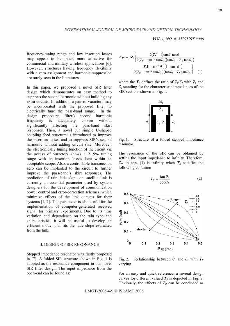
Stepped impedance resonator was firstly proposed in [7]. A folded SIR structure shown in Fig. 1 is adopted as the resonance component in our novel SIR filter design. The input impedance from the open-end can be found as:
( )( )( )
( )( )( ) ( )⎭
⎬⎫
+−−−
−
⎩⎨⎧
+−+
=
2121
22
12
2121
211
tantantantan2tan1tan1
tantantantan2tantan12
θθθθθθ
θθθθθθ
RR
RR
2R
IN
TTT
ΤTTZZ
R
j
where the TR defines the ratio of Z1/Z2 with Z1 and Z2 standing for the characteristic impedances of the SIR sections shown in Fig. 1.
Fig. 1. Structure of a folded stepped impedance resonator. The resonance of the SIR can be obtained by setting the input impedance to infinity. Therefore, ZIN in eqn. (1) is infinity when TR satisfies the following condition
2
1
cottan
θθ
=RT (2)
Fig. 2. Relationship between θ1 and θ2 with TR varying.
For an easy and quick reference, a several design curves for different valued TR is depicted in Fig. 2. Obviously, the effects of TR can be concluded as
2θ2
θ1 θ1
Z2
Z1 Z1
(1)
0 0.1 0.2 0.3 0.4 0.5θ1/π (rad)
0
0.1
0.2
0.3
0.4
0.5
θ 2/ π
(rad
)
0.20.50.811.2525
TRlonger
shorter
320
INTERNATIONAL JOURNAL OF MICROWAVE AND OPTICAL TECHNOLOGY
VOL.1, NO. 2, AUGUST 2006
IJMOT-2006-4-9 © ISRAMT 2006
follows: 1) TR < 1, total length is shorter than half
wavelength; 2) TR = 1, total length is equal to half
wavelength; 3) TR > 1, total length is longer than half
wavelength. Next, we estimate the frequency of second harmonic. Under the resonance condition, the second solution of eqn. (1) stands for the second harmonic frequency value which can be derived from eqn. (3) in terms of TR and the fundamental resonant frequency fo.
⎟⎟⎠
⎞⎜⎜⎝
⎛=
S
oR
ff2
tan 2 πT (3)
It should be mentioned that eqn. (3) is valid only under an assumption that θ1 is nearly identical to θ2. The summery of eqn. (3) states as
a) TR < 1, fs is pushed up from 2 fo; b) TR = 1, fs is equal to 2 fo; c) TR > 1, fs is less than 2 fo;.
Consequently, TR < 1 is chosen for reasons that the circuit not only has a smaller size of circuit, but a wider frequency separation between the fundamental and the second harmonic as well. In the design, an appropriate harmonic location is determined to be 2.25 multiples of our desirable passband’s central frequency, 2.45 GHz, with TR being equal to 0.7. An impractically valued TR might cause a manufacturing precision problem and deteriorates filter’s performance.
III. NOVEL HARMONIC SUPPRESSION METHOD
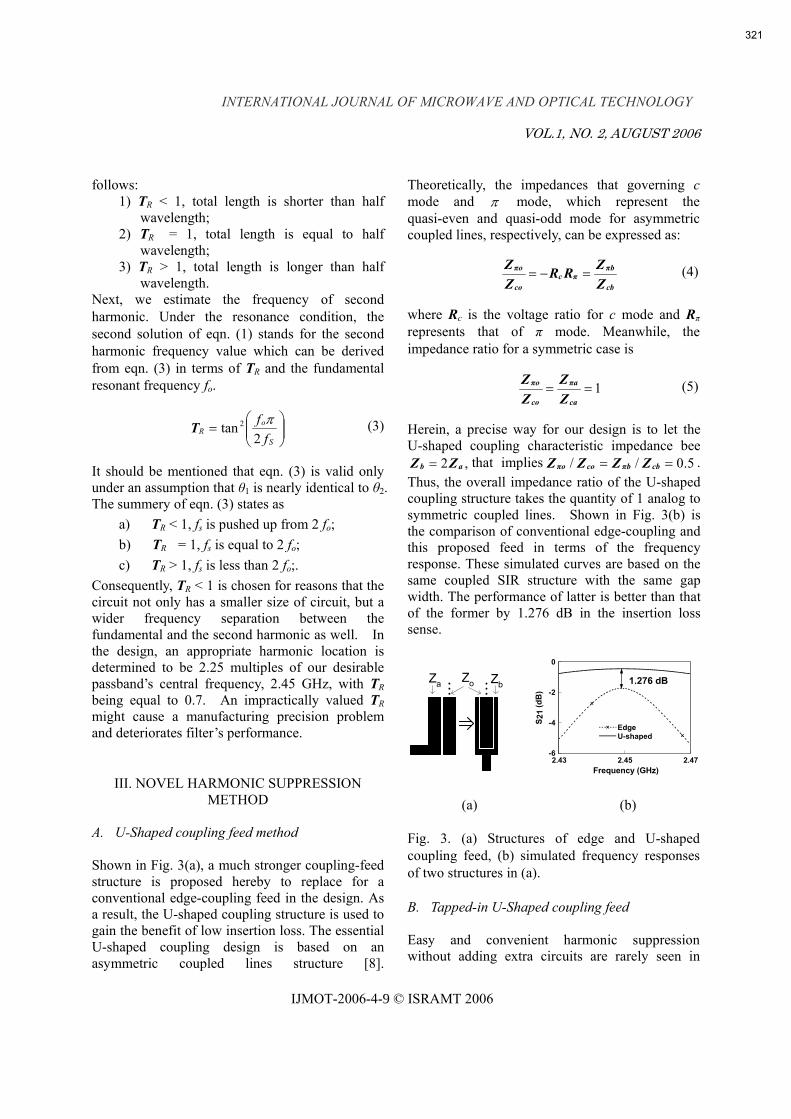
A. U-Shaped coupling feed method Shown in Fig. 3(a), a much stronger coupling-feed structure is proposed hereby to replace for a conventional edge-coupling feed in the design. As a result, the U-shaped coupling structure is used to gain the benefit of low insertion loss. The essential U-shaped coupling design is based on an asymmetric coupled lines structure [8].
Theoretically, the impedances that governing c mode and π mode, which represent the quasi-even and quasi-odd mode for asymmetric coupled lines, respectively, can be expressed as:
cb
πbπc
co
πo
ZZRR
ZZ
=−= (4)
where Rc is the voltage ratio for c mode and Rπ represents that of π mode. Meanwhile, the impedance ratio for a symmetric case is
1==ca
πa
co
πo
ZZ
ZZ (5)
Herein, a precise way for our design is to let the U-shaped coupling characteristic impedance bee
,2 ab ZZ = that implies 5.0// == cbπbcoπo ZZZZ . Thus, the overall impedance ratio of the U-shaped coupling structure takes the quantity of 1 analog to symmetric coupled lines. Shown in Fig. 3(b) is the comparison of conventional edge-coupling and this proposed feed in terms of the frequency response. These simulated curves are based on the same coupled SIR structure with the same gap width. The performance of latter is better than that of the former by 1.276 dB in the insertion loss sense.
(a) (b) Fig. 3. (a) Structures of edge and U-shaped coupling feed, (b) simulated frequency responses of two structures in (a). B. Tapped-in U-Shaped coupling feed Easy and convenient harmonic suppression without adding extra circuits are rarely seen in
Za ZbZo
2.43 2.45 2.47Frequency (GHz)
-6
-4
-2
0
S 21
(dB
)
EdgeU-shaped
1.276 dB
321
INTERNATIONAL JOURNAL OF MICROWAVE AND OPTICAL TECHNOLOGY
VOL.1, NO. 2, AUGUST 2006
IJMOT-2006-4-9 © ISRAMT 2006
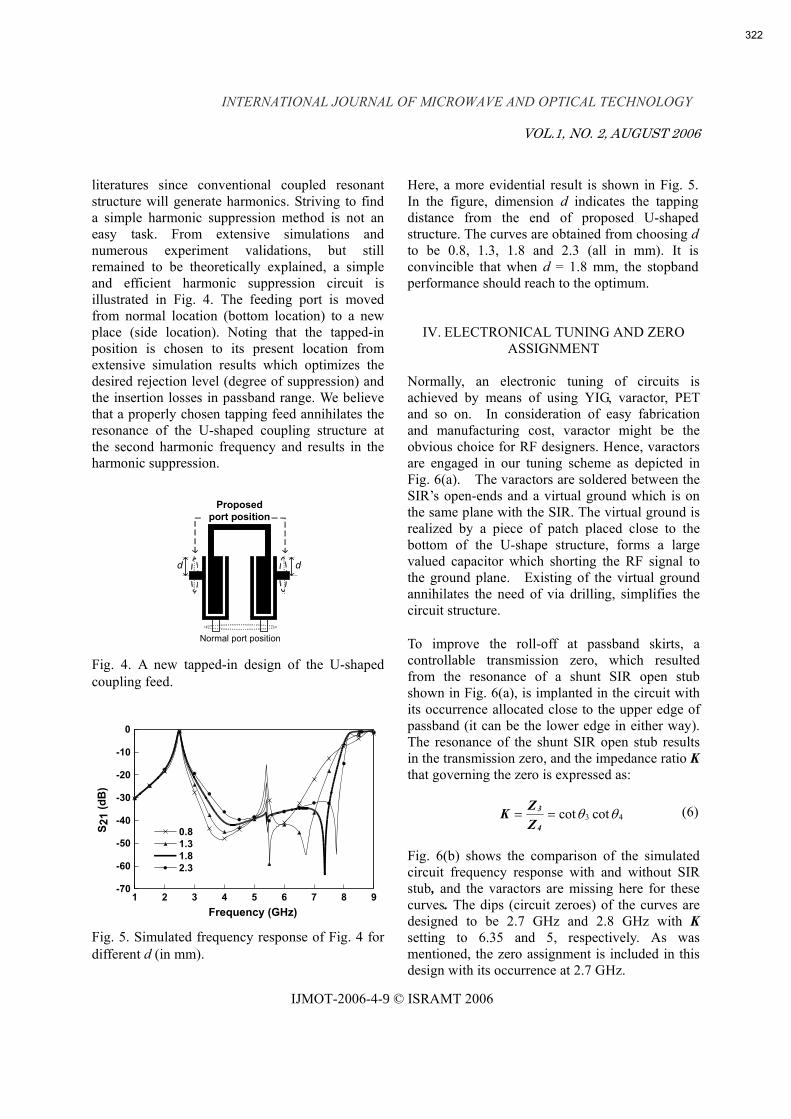
literatures since conventional coupled resonant structure will generate harmonics. Striving to find a simple harmonic suppression method is not an easy task. From extensive simulations and numerous experiment validations, but still remained to be theoretically explained, a simple and efficient harmonic suppression circuit is illustrated in Fig. 4. The feeding port is moved from normal location (bottom location) to a new place (side location). Noting that the tapped-in position is chosen to its present location from extensive simulation results which optimizes the desired rejection level (degree of suppression) and the insertion losses in passband range. We believe that a properly chosen tapping feed annihilates the resonance of the U-shaped coupling structure at the second harmonic frequency and results in the harmonic suppression.
Fig. 4. A new tapped-in design of the U-shaped coupling feed.
Fig. 5. Simulated frequency response of Fig. 4 for different d (in mm).
Here, a more evidential result is shown in Fig. 5. In the figure, dimension d indicates the tapping distance from the end of proposed U-shaped structure. The curves are obtained from choosing d to be 0.8, 1.3, 1.8 and 2.3 (all in mm). It is convincible that when d = 1.8 mm, the stopband performance should reach to the optimum.
IV. ELECTRONICAL TUNING AND ZERO ASSIGNMENT
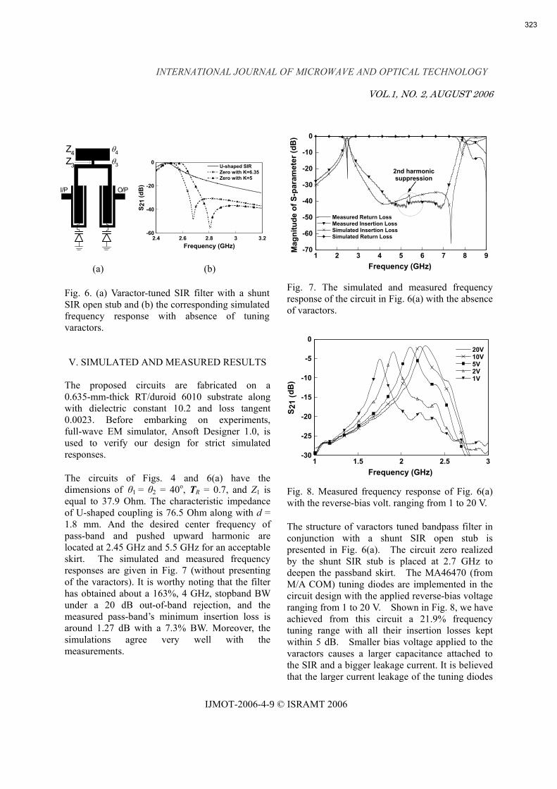
Normally, an electronic tuning of circuits is achieved by means of using YIG, varactor, PET and so on. In consideration of easy fabrication and manufacturing cost, varactor might be the obvious choice for RF designers. Hence, varactors are engaged in our tuning scheme as depicted in Fig. 6(a). The varactors are soldered between the SIR’s open-ends and a virtual ground which is on the same plane with the SIR. The virtual ground is realized by a piece of patch placed close to the bottom of the U-shape structure, forms a large valued capacitor which shorting the RF signal to the ground plane. Existing of the virtual ground annihilates the need of via drilling, simplifies the circuit structure.
To improve the roll-off at passband skirts, a controllable transmission zero, which resulted from the resonance of a shunt SIR open stub shown in Fig. 6(a), is implanted in the circuit with its occurrence allocated close to the upper edge of passband (it can be the lower edge in either way). The resonance of the shunt SIR open stub results in the transmission zero, and the impedance ratio K that governing the zero is expressed as:
43 cotcot θθ==4
3
ZZK (6)
Fig. 6(b) shows the comparison of the simulated circuit frequency response with and without SIR stub, and the varactors are missing here for these curves. The dips (circuit zeroes) of the curves are designed to be 2.7 GHz and 2.8 GHz with K setting to 6.35 and 5, respectively. As was mentioned, the zero assignment is included in this design with its occurrence at 2.7 GHz.
Normal port position
Proposedport position
d d
1 2 3 4 5 6 7 8 9Frequency (GHz)
-70
-60
-50
-40
-30
-20
-10
0
S 21
(dB
)
0.81.31.82.3
322
INTERNATIONAL JOURNAL OF MICROWAVE AND OPTICAL TECHNOLOGY
VOL.1, NO. 2, AUGUST 2006
IJMOT-2006-4-9 © ISRAMT 2006
(a) (b)
Fig. 6. (a) Varactor-tuned SIR filter with a shunt SIR open stub and (b) the corresponding simulated frequency response with absence of tuning varactors. V. SIMULATED AND MEASURED RESULTS
The proposed circuits are fabricated on a 0.635-mm-thick RT/duroid 6010 substrate along with dielectric constant 10.2 and loss tangent 0.0023. Before embarking on experiments, full-wave EM simulator, Ansoft Designer 1.0, is used to verify our design for strict simulated responses.
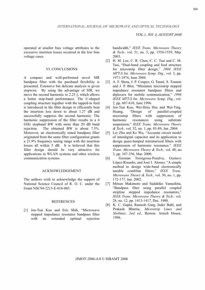
The circuits of Figs. 4 and 6(a) have the dimensions of θ1 = θ2 = 40o, TR = 0.7, and Z1 is equal to 37.9 Ohm. The characteristic impedance of U-shaped coupling is 76.5 Ohm along with d = 1.8 mm. And the desired center frequency of pass-band and pushed upward harmonic are located at 2.45 GHz and 5.5 GHz for an acceptable skirt. The simulated and measured frequency responses are given in Fig. 7 (without presenting of the varactors). It is worthy noting that the filter has obtained about a 163%, 4 GHz, stopband BW under a 20 dB out-of-band rejection, and the measured pass-band’s minimum insertion loss is around 1.27 dB with a 7.3% BW. Moreover, the simulations agree very well with the measurements.
Fig. 7. The simulated and measured frequency response of the circuit in Fig. 6(a) with the absence of varactors. Fig. 8. Measured frequency response of Fig. 6(a) with the reverse-bias volt. ranging from 1 to 20 V.
The structure of varactors tuned bandpass filter in conjunction with a shunt SIR open stub is presented in Fig. 6(a). The circuit zero realized by the shunt SIR stub is placed at 2.7 GHz to deepen the passband skirt. The MA46470 (from M/A COM) tuning diodes are implemented in the circuit design with the applied reverse-bias voltage ranging from 1 to 20 V. Shown in Fig. 8, we have achieved from this circuit a 21.9% frequency tuning range with all their insertion losses kept within 5 dB. Smaller bias voltage applied to the varactors causes a larger capacitance attached to the SIR and a bigger leakage current. It is believed that the larger current leakage of the tuning diodes
I/P O/P
Z4Z3
θ4
θ3
2.4 2.6 2.8 3 3.2Frequency (GHz)
-60
-40
-20
0
S 21
(dB
)
U-shaped SIRZero with K=6.35Zero with K=5
1 2 3 4 5 6 7 8 9Frequency (GHz)
-70
-60
-50
-40
-30
-20
-10
0
Mag
nitu
de o
f S-p
aram
eter
(dB
)
Measured Return LossMeasured Insertion LossSimulated Insertion LossSimulated Return Loss
2nd harmonic suppression
1 1.5 2 2.5 3Frequency (GHz)
-30
-25
-20
-15
-10
-5
0
S 21
(dB
)
20V10V5V2V1V
323
INTERNATIONAL JOURNAL OF MICROWAVE AND OPTICAL TECHNOLOGY
VOL.1, NO. 2, AUGUST 2006
IJMOT-2006-4-9 © ISRAMT 2006
operated at smaller bias voltage attributes to the excessive insertion losses occurred in the low bias voltage cases.
VI. CONCLUSIONS A compact and well-performed novel SIR bandpass filter with the passband flexibility is presented. Extensive but delicate analysis is given stepwise. By using the advantage of SIR, we move the second harmonic to 2.25 fo which allows a better stop-band performance. The U-shaped coupling structure together with the tapped-in feed is introduced in the filter design to efficiently beat the insertion loss down to about 1.27 dB and successfully suppress the second harmonic. The harmonic suppression of the filter results in a 4 GHz stopband BW with more than 20 dB band rejection. The obtained BW is about 7.3%. Moreover, an electronically tuned bandpass filter originated from the same filter configuration grants a 21.9% frequency tuning range with the insertion losses all within 5 dB. It is believed that this filter design should be very attractive for applications in WLAN systems and other wireless communication systems.
ACKNOWLEDGEMENT The authors wish to acknowledge the support of National Science Council of R. O. C. under the Grant NSC94-2213-E-018-003.
REFERENCES
[1] Jen-Tsai Kuo and Eric Shih, “Microwave stepped impedance resonator bandpass filter with an extended optimal rejection
bandwidth,” IEEE Trans. Microwave Theory & Tech., vol. 51, no. 5, pp. 1554-1559, May 2003.
[2] H. M. Lee, C. R. Chen, C. C. Tsai and C. M. Tsai, “Dual-band coupling and feed structure for microstrip filter design,” 2004 IEEE MTT-S Int. Microwave Symp. Dig., vol. 3, pp. 1971-1974, June 2004.
[3] A. F. Sheta, J. P. Coupez, G. Tanné, S. Toutain and J. P. Blot, “Miniature microstrip stepped impedance resonator bandpass filters and diplexers for mobile communication,” 1996 IEEE MTT-S Int. Microwave Symp. Dig., vol. 2, pp. 607-610, June 1996.
[4] Jen-Tsai Kuo, Wei-Hsiu Hsu and Wei-Ting. Huang, “Design of parallel-coupled microstrip filters with suppression of harmonic resonances using substrate suspension,” IEEE Trans. Microwave Theory & Tech., vol. 52, no. 1, pp. 83-89, Jan. 2004.
[5] Lei Zhu and Ke Wu, “Accurate circuit model of interdigital capacitor and its application to design quasi-lumped miniaturized filters with suppression of harmonic resonance,” IEEE Trans. Microwave Theory & Tech., vol. 48, no. 3, pp. 347-356, Mar. 2000.
[6] Germán Torregrosa-Penalva, Gustavo López-Risueño, and José I. Alonso, “A simple method to design wide-band electronically tunable combline filters,” IEEE Trans. Microwave Theory & Tech., vol. 50, no. 1, pp. 172-177, Jan. 2002.
[7] Mitsuo Makimoto and Sadahiko Yamashita, “Bandpass filter using parallel coupled stripline stepped impedance resonators,” IEEE Trans. Microwave Theory & Tech., vol. 28, no. 12, pp. 1413-1417, Dec. 1980.
[8] K. C. Gupta, Ramesh Garg, Inder Bahl, and Prakash Bhartia, Microstrip Lines and Slotlines, 2nd ed., Boston: Artech House, 1996.
324