A training report on 132 KV GSS, BHADOTI, sawai madhopur
66
CHAPTER-1 INTRODUCTION 1.1 AN OVERVIEW OF R.S.E.B. “Rajasthan State Electricity Board” started working form 1 July, 1957. When India became independent its overall installed capacity was hardly 13.27 MW. During first year plan (1951-1956) this capacity was only 2300 MW. The contribution of Rajasthan state was negligible during 1 & 2 year plans the emphasis was on industrialization for that end it was considered to make the system of the country reliable. Therefore Rajasthan state electricity board came into existence in July 1957. In 1957 RSEB (Rajasthan State Electric Board) comes in to existence and it satisfactorily work from 1 July 1957 at that time energy level in Rajasthan is very low. The 1 st survey for energy capacity in Rajasthan is held in 1989 at that time the total electric energy capacity of Rajasthan is 20116 MW. At that time the main aim of RSEB is to supply electricity to entire Rajasthan in the most economical way. RAJASTHAN RAJYA VIDYUT PRASARAN NIGAM LIMITED (RRVPNL) a company under the companies Act, 1956 and registered with Registrar of companies “RAJASTHAN RAJYA VIDYUT PRASARAN NIGAM LIMITED” vide No. 17-016485 of 2000-2001 with its registered Office at VIDYUT BHAWAN, JYOTI NAGAR, JAIPUR-302005 has been established on 19 July, 2000 by Govt. of Rajasthan Power Sector Reform act 1999 as the successor company of RSEB. The aim of RSEB is to supply electricity to entire Rajasthan state in the most economical way. Government of Rajasthan on 19th July 2000, issued a gazette notification unbundling Rajasthan State Electricity Board into RAJASTHAN RAJYA VIDYUT 1
-
Upload
dilkhush009 -
Category
Engineering
-
view
442 -
download
34
Transcript of A training report on 132 KV GSS, BHADOTI, sawai madhopur
CHAPTER-1
INTRODUCTION
1.1 AN OVERVIEW OF R.S.E.B.
“Rajasthan State Electricity Board” started working form 1 July, 1957. When India became independent its overall installed capacity was hardly 13.27 MW. During first year plan (1951-1956) this capacity was only 2300 MW. The contribution of Rajasthan state was negligible during 1 & 2 year plans the emphasis was on industrialization for that end it was considered to make the system of the country reliable. Therefore Rajasthan state electricity board came into existence in July 1957.
In 1957 RSEB (Rajasthan State Electric Board) comes in to existence and it satisfactorily work from 1 July 1957 at that time energy level in Rajasthan is very low. The 1 st survey for energy capacity in Rajasthan is held in 1989 at that time the total electric energy capacity of Rajasthan is 20116 MW. At that time the main aim of RSEB is to supply electricity to entire Rajasthan in the most economical way.
RAJASTHAN RAJYA VIDYUT PRASARAN NIGAM LIMITED (RRVPNL) a company under the companies Act, 1956 and registered with Registrar of companies “RAJASTHAN RAJYA VIDYUT PRASARAN NIGAM LIMITED” vide No. 17-016485 of 2000-2001 with its registered Office at VIDYUT BHAWAN, JYOTI NAGAR, JAIPUR-302005 has been established on 19 July, 2000 by Govt. of Rajasthan Power Sector Reform act 1999 as the successor company of RSEB.
The aim of RSEB is to supply electricity to entire Rajasthan state in the most economical way. Government of Rajasthan on 19th July 2000, issued a gazette notification unbundling Rajasthan State Electricity Board into RAJASTHAN RAJYA VIDYUT UTPADAN NIGAM LTD (RRVUNL), the generation Company; RAJASTHAN RAJYA VIDYUT PRASARAN NIGAM LTD, (RRVPNL), the transmission Company and the three regional distribution companies namely JAIPUR VIDYUT VITRAN NIGAM LTD, (JVVNL) AJMER VIDYUT VITRAN NIGAM LTD (AVVNL) and JODHPUR VIDYUT VITRAN NIGAM LTD (JDVVNL)
The Generation Company owns and operates the thermal power stations at KOTA and SURATGARH, Gas based power station at RAMGARH, HYDEL power station at MAHI and mini HYDEL stations in the State
The Transmission Company operates all the 765KV, 400KV, 220 KV, 132 KV and 33KV electricity lines and system in the State.
The three distribution Companies operate and maintain the electricity system below 66KV in the State in their respective areas
1

Rajasthan State Electricity Board has been divided in five main parts :-
● Electricity production authority - RRVUNL
● Electricity transmission authority - RRVPNL
● Distribution authority for JAIPUR - JVVNL
● Distribution authority for JODHPUR - JDVVNL
● Distribution authority for AJMER - AVVNL
Power obtain from these stations is transmitted all over Rajasthan with the help of grid stations. Depending on the purpose, substations are classified as:-
1. Step up substation2. Primary grid substation3. Secondary substation4. Distribution substation5. Bulky supply and industrial substation6. Mining substation7. Mobile substation8. Cinematograph substation
Depending on constructional feature substation are classified as:-
1. Outdoor type2. Indoor type3. Basement or Underground type4. Pole mounting open or kilos type
2

CHAPTER-2
SUB STATION
2.1 INTRODUCTION
A substation is a part of an electrical generation, transmission, and distribution system. A substation is an assembly of apparatus, which transform the characteristics of electrical energy from one form to another say from one voltage level to another level. Hence a substation is an intermediate link between the generating station and consumer.
For economic transmission the voltage should be high so it is necessary to step up the generated voltage for transmission and step down transmitted voltage for distribution. For this purpose substations are installed. The normal voltages for transmission are 400KV, 220KV, 132KV and for distribution 33KV, 11KV etc.
2.2 132KV GSS BHADOTI, SAWAI MADHOPUR
132 KV GSS BHADOTI is situated 28.5 km away from SAWAI MADHOPUR. 132 KV GSS RVPNL BHADOTI is a part of ISO 9001:2008 certified company. The power mainly comes from 132 KV SAWAI MADHOPUR and 132 KV BAGADI. In This 132 KV GSS the incoming 132 KV supply is stepped down to 33 KV with the help of transformers which is further supplied to different sub-station according to the load.
132 KV GSS BHADOTI has a large layout consisting of two numbers of transformer one is 20/25 MVA and other 10/12 MVA transformers having voltage ratio respectively 132/33 KV in addition to these transformers. And a 250 KVA, 33 KV/0.4 KV Station Transformer gives the supply to the control room and electrical equipment of GSS.
There are two bus bars in 132 KV yard and also two bus-bars in 33 KV yard. The incoming feeders are connected to bus-bar through circuit breakers, Isolators, lightning arrestors, current-transformers etc. The bus-bars are to have an arrangement of auxiliary bus So that when some repairing work is to be done an main bus the whole load can be transferred to the auxiliary bus through bus-coupler.
2.2.1 INCOMING FEEDERS1. 132KV SAWAI MADHOPUR2. 132 KV BAGADI
2.1.2 OUTGOING FEEDERS
1. 33 KV BONLI2. 33 KV BHADOTI3. 33 KV BAD BICHHODANA4. 33 KV MALARNA CHOR5. 33 KV KODYAI6. 33 KV BPCL
3

In this substation, there are two yards
Fig.2.1 132 KV yard
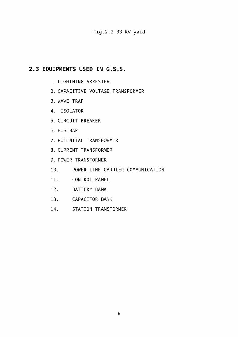
Fig.2.2 33 KV yard
4

2.3 EQUIPMENTS USED IN G.S.S.
1. LIGHTNING ARRESTER
2. CAPACITIVE VOLTAGE TRANSFORMER
3. WAVE TRAP
4. ISOLATOR
5. CIRCUIT BREAKER
6. BUS BAR
7. POTENTIAL TRANSFORMER
8. CURRENT TRANSFORMER
9. POWER TRANSFORMER
10. POWER LINE CARRIER COMMUNICATION
11. CONTROL PANEL
12. BATTERY BANK
13. CAPACITOR BANK
14. STATION TRANSFORMER
5
6

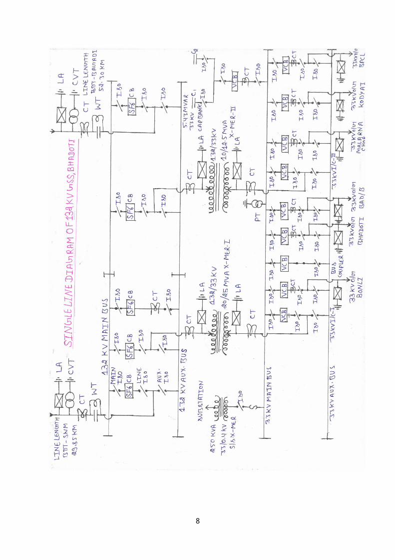
Fig. 2.3 Single Line Diagram of 132 KV GSS BHADOTI
7
CHAPTER-3
LIGHTNING ARRESTER
3.1 INTRODUCTION
Lightning arrestor is a device, which protects the overhead lines and other electrical apparatus viz., transformer from overhead voltages and Lightning. An electric discharge between cloud and earth, between cloud and the charge centers of the same cloud is known as lightning. Lightning arrester is connected between line and earth i.e. in parallel with the over headline, HV equipments and substation to be protected. It is a safety valve which limits the magnitude of lightning and switching over voltages at the substations, over headlines and HV equipment and provides a low resistance path for the surge current to flow to the ground. The practice is also to install lightning arresters at the incoming terminals of the line.
The lightning arrester (or) the lightning conductor is a commonly used device which is used to protection a substation is essential:
1. Protection for transmission line from direct stroke.2. Protection of Power station and sub-station from direct stroke.3. Protection of electrical apparatus against traveling waves.4. Effective protection of equipment against direct strokes requires a shield to
prevent lightning from striking the electrical conductor together with adequate drainage facilities over insulated structure.
3.2 TYPES OF LIGHTNING ARRESTER
3.2.1 ROD SPHERE TYPE
It is a very simple protective device i.e. gap is provided across the stack of Insulation to permit flash-over when undesirable voltages are impressed of the system.
3.2.2 EXPULSION TYPE
It have two electrodes at each end and consists of a fiber tube capable of producing a gas when is produced. The gas so evolved blows the arc through the bottom electrode.
3.2.3 VALVE TYPE
It consists of a divided spark-gap in series will a non linear resistor. The divided spark gap consists of a no. of similar elements, each of two electrodes across which are connected high resistor.
3.2.4 THYRITE TYPE
Ground wire run over the tower provides an adequate protection against lightning and reduce the induced electrostatic or electromagnetic voltage but such a shield is inadequate to protect any traveling wave, which reaches the terminal of the electrical equipment, and such wave can cause the following damage.
8

1. The high peak of the surge may cause a flashover in the internal wiring thus it may spoil the insulation of the winding.
2. The steep wave front may cause internal flash over between their turns of transformer. The stop wave front resulting into resonance and high voltage may cause internal or external flashover causing building up the electrical operation.
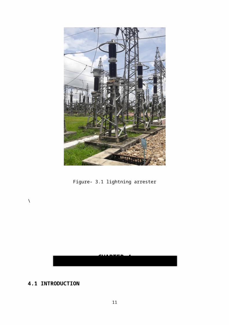
Figure- 3.1 lightning arrester
\
9
CHAPTER-4
CAPACITIVE VOLTAGE TRANSFORMER
4.1 INTRODUCTION
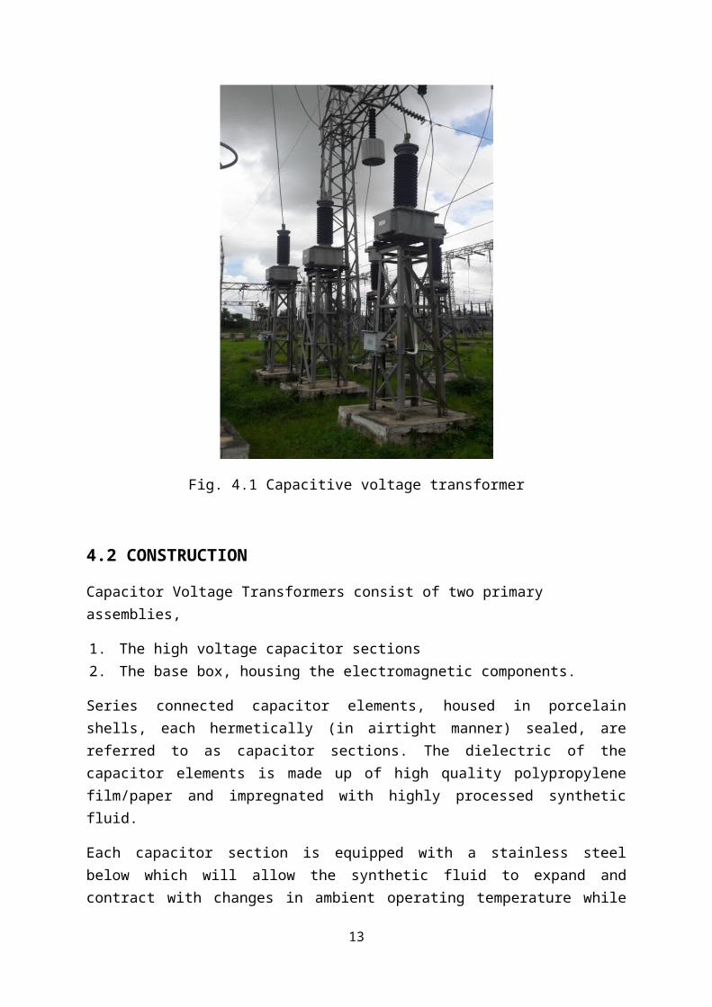
A capacitor voltage transformer (CVT) is a transformer used in power systems to step down extra high voltage signals and provide a low voltage signal, for measurement or to operate a protective relay. Capacitor Voltage Transformers also serve as coupling capacitors for coupling high frequency power line carrier signals to the transmission line. CVTs in combination with wave traps are used for filtering high frequency communication signals from power frequency. This forms a carrier communication network throughout the transmission network. In an electrical power substation, Capacitor Voltage Transformer in combination with Wave Trap is placed at the sending and receiving ends of the substation. At the receiving end they are found just after lightening arrester and before line isolator.
Another form of capacitor voltage transformer is one that is either attached to or run in sequence with something called a capacitance coupled voltage transformer, or CCVT. These types of transformers are used in the same manner, however, they are able to handle much higher amounts of input signal. They are also able to distribute the lower amounts of output signal to multiple locations within the circuit at the same time.
Fig. 4.1 Capacitive voltage transformer
10
4.2 CONSTRUCTION
Capacitor Voltage Transformers consist of two primary assemblies,
1. The high voltage capacitor sections2. The base box, housing the electromagnetic components.
Series connected capacitor elements, housed in porcelain shells, each hermetically (in airtight manner) sealed, are referred to as capacitor sections. The dielectric of the capacitor elements is made up of high quality polypropylene film/paper and impregnated with highly processed synthetic fluid.
Each capacitor section is equipped with a stainless steel below which will allow the synthetic fluid to expand and contract with changes in ambient operating temperature while maintaining the hermetic sealing. It is over these capacitor sections that most of the high voltage will be dropped.
A tap voltage (approximately 5-12 kV depending on type) is taken from the lowest capacitor section and fed to an electromagnetic circuit in the cast aluminum base box. The base box contains the intermediate transformer which will provide the final output voltages via multiple tapped secondary windings, series compensating reactor and ferro-resonance control circuitry. The base box is filled with dried mineral oil, protecting the components from environmental deterioration. Ferro-resonance is simply and effectively controlled by utilization of low flux density designed magnetic circuitry and a saturable reactor controlled damping circuit connected across the secondary winding. The ferro-resonance suppression circuit does not adversely affect transient response.
4.3 APPLICATION
1. Voltage Measuring: They accurately transform transmission voltages down to useable levels for revenue metering, protection and control purposes.
2. Insulation: They guarantee the insulation between HV network and LV circuits ensuring safety condition to control room operators.
3. HF Transmissions: They can be used for Power Line Carrier (PLC) coupling.4. Transient Recovery Voltage: When installed in close proximity to HV/EHV Circuit
Breakers, CVT’s own High Capacitance Enhance C/B short line fault / TRV performance.
11

CHAPTER-5
POTENTIAL TRANSFORMER
5.1 INTRODUCTION
Potential transformer or voltage transformer gets used in electrical power system for stepping down the system voltage to a safe value which can be fed to low ratings meters and relays. Commercially available relays and meters used for protection and metering, are designed for low voltage. Primary of this transformer is connected across the phase and ground. Just like the transformer used for stepping down purpose, potential transformer i.e. PT has lower turns winding at its secondary. The system voltage is applied across the terminals of primary winding of that transformer, and then proportionate secondary voltage appears across the secondary terminals of the PT.
Potential Transformer is designed for monitoring single-phase and three-phase power line voltages in power metering applications. The primary terminals can be connected either in line-to-line or in line-to-neutral configuration. Fused transformer models are designated by a suffix of "F" for one fuse or "FF" for two fuses. A Potential Transformer is a special type of transformer that allows meters to take readings from electrical service connections with higher voltage than the meter is normally capable of handling without at potential transformer.
Fig. 5.1 Potential Transformer
12
CHAPTER-6
CURRENT TRANSFORMER
6.1 INTRODUCTION
Current transformer is used for monitoring the current for the purpose of measuring and protection. They can be classified as dead tank inverter type. The dead tank current transformer accommodates the secondary core inside the tank, which is at the ground potential. The insulated primary passes through the porcelain and the tank and the terminals into the top chamber. The primary used in such types of construction is of ‘U’ type. The inserted secondary cores are insulated to the system voltage and hence inside the top chamber which is at the line potential. Before commissioning of the current transformer the earthing of the power terminal and base is essential, otherwise excessive high voltage appears at the power factor terminals and leads to heavy spark. The secondary terminal of the core should be short circuited and earthed which are not in use otherwise excessive high voltage will be developed across the current transformer secondary. The current transformer should always be in vertical position so that gas forming at the top does not enter the insulated part. The current transformer actually steps down the current so that it can be measured by standard measuring instrument. There are three current transformers in each feeder. The current transformers are inserted into energy incoming and outgoing feeder from 132 kV systems for measurement. The current transformer is used with its primary winding connected in series with the line carrying the current to be measured and therefore the primary current is not determined by the load on the secondary of the current transformer. The primary consists of a very few turns and there is no appreciable voltage across it. The secondary consists of a very large number of turns. The ammeter or wattmeter current coil is connected directly across the secondary terminals thus a current transformer operates its secondary nearly under short circuit conditions. The secondary circuit is connected to ground in many cases. Instrument transformers perform two important functions: they serve to extend the range of the measuring instrument, much as the shunt or the multiplier extends the range of the dc ammeter. They also serve to isolate the measuring instrument from the high voltage power line. The primary winding of the current line transformer is connected directly to the load circuit, while the secondary is open circuited. The voltage across the open terminal can be very high (because of the step up ratio) and could easily break down the insulation between the secondary windings. The secondary winding of a current transformer should therefore always be short circuited or connected to a relay coil.
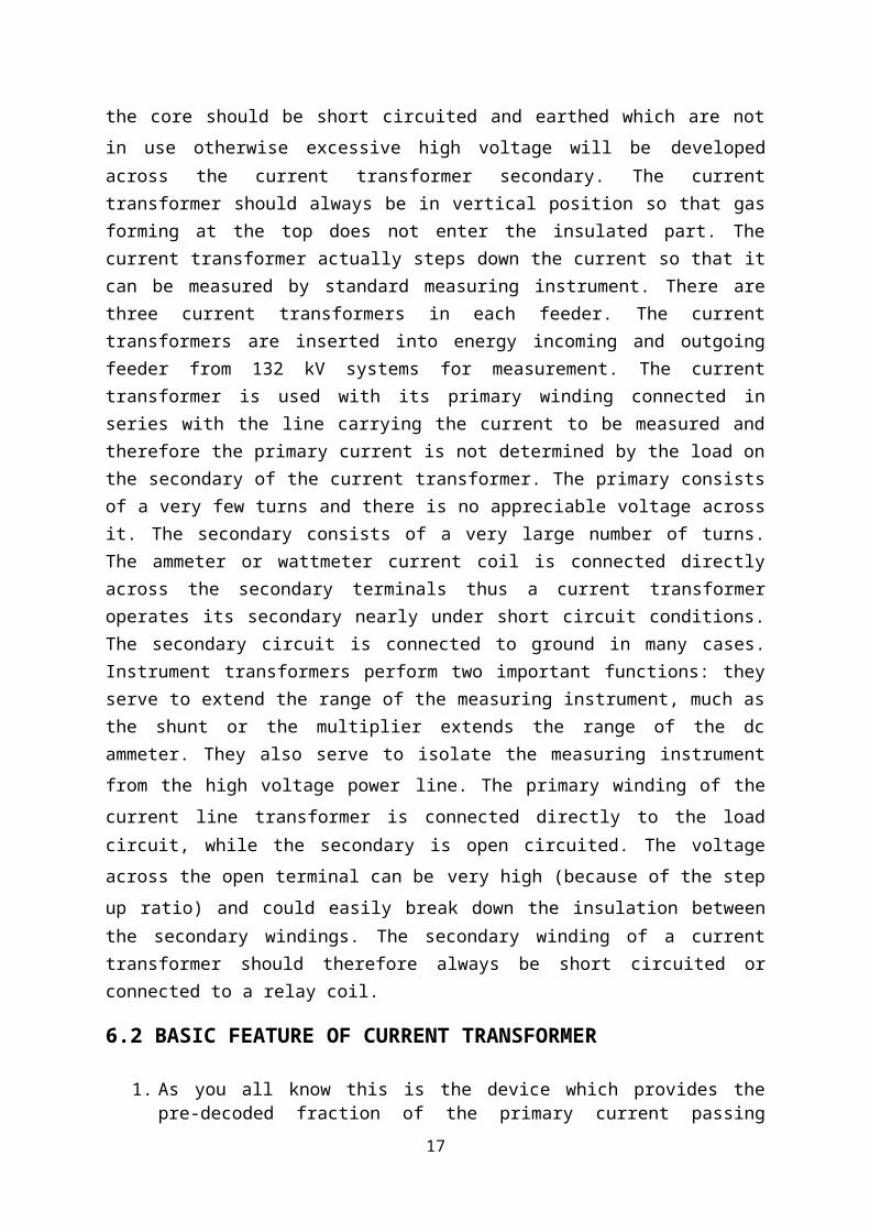
6.2 BASIC FEATURE OF CURRENT TRANSFORMER
1. As you all know this is the device which provides the pre-decoded fraction of the primary current passing through the line /bus main circuit. Such as primary current 60A, 75A, 100A, 120A, 150, 240A, 300A, 400A, to the secondary output of 1A to 5A.
13
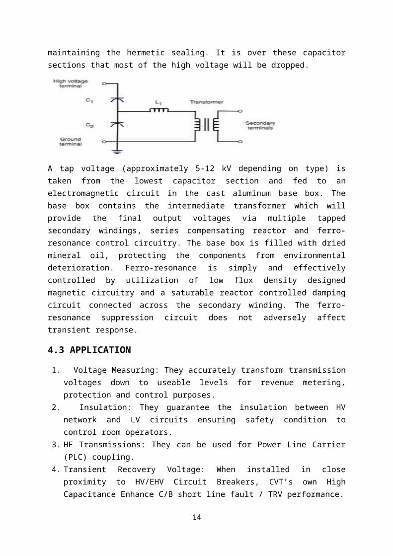
Fig. 6.1 Current transformer
2. Now a day mostly separate current transformers units are used instead of bushing mounting CT’s on leveled structure they should be for oil level indication and the base should be earthed properly. Care should be taken so that there should be no strain on the terminal.
3. Current transformers can be used to supply information for measuring power flows and the electrical inputs for the operation of protective relays associated with the transmission and distribution circuits or for power transformers. These current transformers have the primary winding connected in series with the conductor carrying the current to be measured or controlled. The secondary winding is thus insulated from the high voltage and can then be connected to low-voltage metering circuits.
14
CHAPTER-7
INSULATOR
7.1 INTRODUCTION
These are porcelain or fibreglass insulators that serve to isolate the bus bar switches and other support structures and to prevent leakage current from flowing through the structure or to ground. These insulators are similar in function to other insulators used in substations and transmission poles and towers. These insulators are generally made of glazed porcelain or toughened glass. Poly come type insulator [solid core] are also being supplied in place of hast insulators if available indigenously. The design of the insulator is such that the stress due to contraction and expansion in any part of the insulator does not lead to any defect. It is desirable not to allow porcelain to come in direct contact with a hard metal screw thread.
7.2 TYPES OF INSULATOR
7.2.1 PIN TYPE
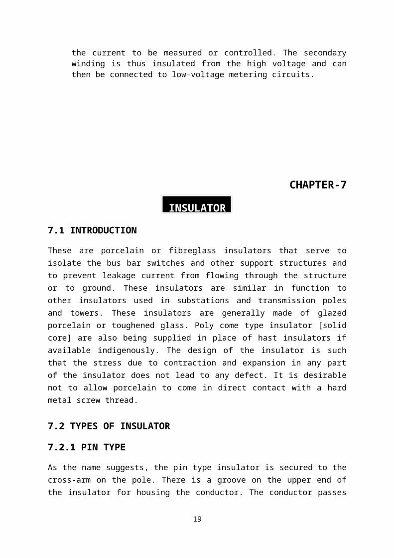
As the name suggests, the pin type insulator is secured to the cross-arm on the pole. There is a groove on the upper end of the insulator for housing the conductor. The conductor passes through this groove and is bound by the annealed wire of the same material as the conductor. Pin type insulators are used for transmission and distribution of electric power at voltages up to 33 kV. Beyond operating voltage of 33 kV, the pin type insulators become too bulky and hence uneconomical.
Fig. 7.1 Pin Type Insulator
15

7.2.2 SUSPENSION TYPE
For high voltages (>33 kV), it is a usual practice to use suspension type insulators shown in Figure 14.1. Consists of a number of porcelain discs connected in series by metal links in the form of a string. The conductor is suspended at the bottom end of this string while the other end of the string is secured to the cross-arm of the tower. Each unit or disc is designed for low voltage, say 11 kV. The number of discs in series would obviously depend upon the working voltage. For instance, if the working voltage is 66 kV, then six discs in series will be provided on the string.
Fig. 7.2 Suspension Type Insulator
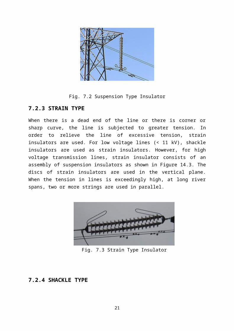
7.2.3 STRAIN TYPE
When there is a dead end of the line or there is corner or sharp curve, the line is subjected to greater tension. In order to relieve the line of excessive tension, strain insulators are used. For low voltage lines (< 11 kV), shackle insulators are used as strain insulators. However, for high voltage transmission lines, strain insulator consists of an assembly of suspension insulators as shown in Figure 14.3. The discs of strain insulators are used in the vertical plane. When the tension in lines is exceedingly high, at long river spans, two or more strings are used in parallel.
Fig. 7.3 Strain Type Insulator
16
7.2.4 SHACKLE TYPE
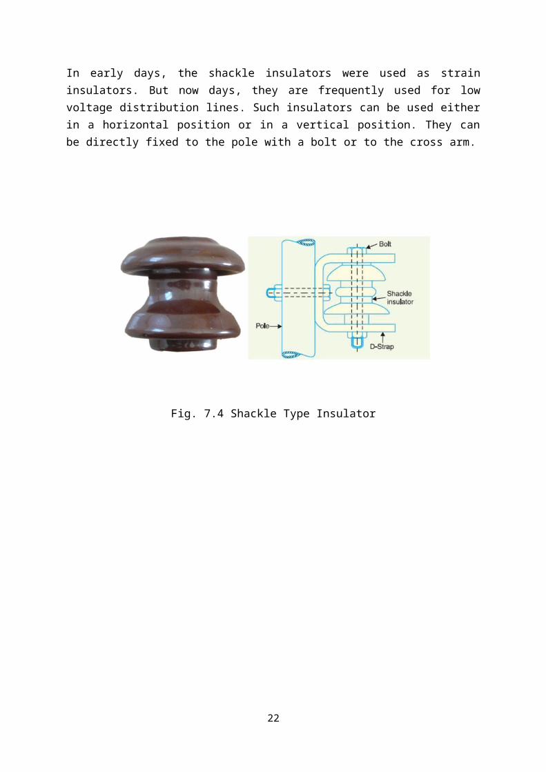
In early days, the shackle insulators were used as strain insulators. But now days, they are frequently used for low voltage distribution lines. Such insulators can be used either in a horizontal position or in a vertical position. They can be directly fixed to the pole with a bolt or to the cross arm.
Fig. 7.4 Shackle Type Insulator
17

CHAPTER-8
BUS BAR
8.1 INTRODUCTION
A bus bar is defined as a conductor or a group of conductor used for collecting electrical
energy from the incoming feeders and distributes them to the outgoing feeders. In other
word, it is a type of electrical junction in which all the incoming and outgoing electrical
current meets. Thus, the electrical bus bar collects the electrical energy at one location.
When the fault occurs in any section of the bus bar, all the circuit equipment connected to
that section must be tripped to give complete isolation in the shortest possible time. A bus bar
is a metallic strip or bar that conducts electricity within a switchboard, distribution board,
substation, battery bank, or other electrical apparatus. Bus bars are used to carry substantial
electric currents over relatively short distances. Their greater surface area reduces losses due
to corona discharge. Bus bars are not normally structural members. Bus bars are typically
contained inside switchgear, panel boards, and bus way enclosures. They are also used to
connect high voltage equipment at electrical switchyards. Distribution boards split the
electrical supply into separate circuits at one location. Bus ways, or bus ducts are long bus bar
with a protective cover. Rather than branching from the main supply at one location, they
allow new circuits to branch off anywhere along the route of the bus way.
A bus bar may either be supported on insulators, or else insulation may completely surround
it. Bus bars are protected from accidental contact either by a metal earthed enclosure or by
elevation out of normal reach. Bus bars may be connected to each other and to electrical
apparatus by bolted, clamped, or welded connections. Often, joints between high-current bus
sections have precisely-machined matching surfaces that are silver-plated to reduce the
contact resistance. At extra high voltages (more than 300 kV) in outdoor buses, corona
discharge around the connections becomes a source of radio-frequency interference and
power loss, so special connection fittings designed for these voltages are used. There are two
buses running parallel to the each other, one main and another is auxiliary bus only for
standby, in case of failure of one we can keep the supply continues. If more loads are coming
at the GSS then we can disconnect any feeder through circuit breaker which is connected to
the bus bar. This remaining all the feeders will be in running position. If we want to work
with any human damage, in this case all the feeders will be on conditions
18
8.2 BUS BAR ARRANGEMENT MAY BE OF FOLLOWING TYPE
WHICH IS BEING ADOPTED BY RRVPNL
8.1.1. Single bus bar arrangement
8.1.2. Double bus bar arrangement
a) Main bus with transformer bus
b) Main bus-I with main bus-II
8.1.3. Double bus bar arrangement with auxiliary bus.
8.2.1 SINGLE BUS BAR ARRANGEMENT
This arrangement is simplest and cheapest. It suffers, however, from major defects.
1. Maintenance without interruption is not possible.
2. Extension of the sub-station without a shutdown is not possible.
8.2.2 DOUBLE BUS BAR ARRANGEMENT 1. Each load may be fed from either bus.
2. The load circuit may be divided in to two separate groups if needed from
operational consideration. Two supplies from different sources can be put
on each bus separately.
3. Either bus bar may be taken out from maintenance of insulators.
The normal bus selection insulators cannot be used for breaking load currents. The
arrangement does not permit breaker maintenance without causing stoppage of supply.
19
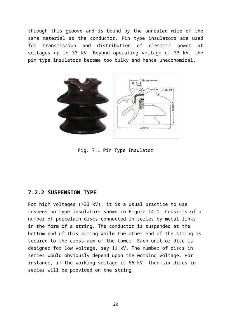
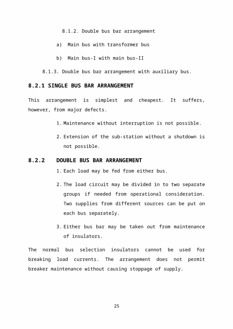
Fig. 8.1 Bus bar
8.2.3 DOUBLE BUS BAR ARRANGEMENTS CONTAINS MAIN BUS
WITH AUXILARY BUS
The double bus bar arrangement provides facility to change over to either bus to carry out
maintenance on the other but provide no facility to carry over breaker maintenance. The main
and transfer bus works the other way round. It provides facility for carrying out breaker
maintenance but does not permit bus maintenance. Whenever maintenance is required on any
breaker the circuit is changed over to the transfer bus and is controlled through bus coupler
breaker.
20
CHAPTER-9
ISOLATOR
9.1 INTRODUCTION
When to carry out inspection or repair in the substation installation a disconnection switch is
used called isolator. Isolators are also called as disconnect switches or air break switches. Its
work is to disconnect the unit or section from all other line parts on installation in order to
insure the complete safety of staff working. The isolator works at no load condition. They do
not have any making or breaking capacity.
Isolators are used to isolate the bus when it is not in working condition. If the bus is to be
shut down then it is isolated from the main bus. The moving and fixed contacts is done so
that all the three phase of the isolator close and open simultaneously and there is a full
surface contact between moving and fixed contacts.
Following type of isolator are being used in RSEB,
a. Isolator without earth blades.
b. Isolator with earth blades.
c. Tendon isolator.
Fig. 9.1 Isolator
21
On fundamental basis the isolating switches can broadly divided into following categories
1. Bus isolator
2. Line isolator cum earthing switch
3. Transformer isolating switch
\
9.2 OPERATION
The operation of an isolator may be hand operated without using any supply or may be power
operated which uses externally supplied energy switch which is in the form of electrical
energy or energy stored in spring or counter weight.
In a horizontal break, center rotating double break isolator, 3 strokes are found. Poles are
provided on each phase. The two strokes on side are fixed and center one is rotating. The
center position can rotate about its vertical axis at an angle of 90o. In closed position, the
isolating stroke mounts on galvanized steel rolled frame. The three poles corresponding to 3
phases are connected by means of steel shaft.
Isolators are of two types-
1. Single pole isolator
2. Three pole isolator
22

CHAPTER-10
CIRCUIT BREAKER
10.1 INTRODUCTION
A circuit breaker is an automatically operated electrical switch designed to protect an electrical circuit from damage caused by overload or short circuit. Its basic function is to detect a fault condition and, by interrupting continuity, to immediately discontinue electrical flow. Unlike a fuse, which operates once and then has to be replaced, a circuit breaker can be reset (either manually or automatically) to resume normal operation. Circuit breakers are made in varying sizes, from small devices that protect an individual household appliance up to large switchgear designed to protect high voltage circuits feeding an entire city.
In any circuit, carrying a large amount of current, if a contact is opened then normally a spark is produced due to fact that current traverses its path through air gap Arcing is harmful as it can damage precious equipment media are provided between contacts. This is one of the important equipment in power system. It protects the system by isolating the faulty section while the healthy one is keep on working. Every system is susceptible to fault or damages while can be caused due to overloading, short-circuiting, earth fault etc. thus to protect the system and isolate the faulty section CB are required. Apart from breaking and making contacts, a CB should be capable of doing
1. Continuously carry the maximum current at point of installation 2. Make and break the circuit under abnormal and normal condition 3. Close or open the faulty section only where fault exists
There are different arc quenching media:-
1. SF6 gas
2. Vacuum
In 132 KV GSS, SF6 gas circuit breakers are used, as for greater capacity GSS SF6 type breakers are very efficient.
10.2 TYPES OF CIRCUIT BREAKER
1. SF6 Circuit Breaker
2. Vacuum Circuit Breaker
3. Minimum Oil Circuit Breaker
4. Air Blast Circuit Breaker
23

10.2.1 SF6 CIRCUIT BREAKER
Sulphur hexafluoride has proved its-self as an excellent insulating and arc quenching medium. The physical, chemical, and electrical properties of SF6 are more superior to many of the other media. It has been extensively used during the last 30 years in circuit breakers, gas-insulated switchgear (GIS), high voltage capacitors, bushings, and gas insulated transmission lines. In SF6 breakers the contacts are surrounded by low pressure SF6 gas. At the moment the contacts are opened, a small amount of gas is compressed and forced through the arc to extinguish it.
Fig. 10.1 SF6 Circuit Breaker
10.2.2 VACUUM CIRCUIT BREAKER
A vacuum circuit breaker is such kind of circuit breaker where the arc quenching takes place in vacuum. The technology is suitable for mainly medium voltage application. For higher voltage Vacuum technology has been developed but not commercially visible. The operation of opening and closing of current carrying contacts and associated arc interruption take place
24
in a vacuum chamber in the breaker which is called vacuum interrupter. The vacuum interrupter consists of a steel arc chamber in the centre symmetrically arranged ceramic insulators. The material used for current carrying contacts plays an important role in the performance of the vacuum circuit breaker. Cu Cr is the most ideal material to make VCB contacts. Vacuum interrupter technology was first introduced in the year of 1960. But still it is a developing technology. As time goes on, the size of the vacuum interrupter is being reducing from its early 1960’s size due to different technical developments in this field of engineering. The contact geometry is also improving with time, from butt contact of early days it gradually changes to spiral shape, cup shape and axial magnetic field contact. The vacuum circuit breaker is today recognized as most reliable current interruption technology for medium voltage system. It requires minimum maintenance compared to other circuit breaker technologies.
ADVANTAGES
1. Very long lifetime of the contacts (This provides longer breaker life.)2. Less maintenance required3. Less moving parts in mechanism4. Less force needed to separate the contacts (since the distance between them is shorted)5. Environment friendly. Since interruption takes place in vacuum medium, VCBs do not
require gas or liquid addition. This reduces the possibility of leakage of gas (or any material) that can be harmful for environment.
Fig. 10.2 Vacuum Circuit Breaker
25
10.2.3 MINIMUM OIL CIRCUIT BREAKER
Bulk oil circuit breakers have the disadvantage of using large quantity of oil. With frequent breaking and making heavy currents the oil will deteriorate and may lead to circuit breaker failure. This has led to the design of minimum oil circuit breakers working on the same principles of arc control as those used in bulk oil breakers. In this type of breakers the interrupter chamber is separated from the other parts and arcing is confined to a small volume of oil. The lower chamber contains the operating mechanism and the upper one contains the moving and fixed contacts together with the control device. Both chambers are made of an insulating material such as porcelain. The oil in both chambers is completely separated from each other. By this arrangement the amount of oil needed for arc interruption and the clearances to earth are roused. However, conditioning or changing the oil in the interrupter chamber is more frequent than in the bulk oil breakers. This is due to carbonization and slugging from arcs interrupted chamber is equipped with a discharge vent and silica gel breather to permit a small gas cushion on top of the oil. Single break minimum oil breakers are available in the voltage range 13.8 to 34.5 KV.
10.2.4 AIR BLAST CIRCUIT BREAKER
The principle of arc interruption in air blast circuit breakers is to direct a blast of air, at high pressure and velocity, to the arc. Fresh and dry air of the air blast will replace the ionized hot gases within the arc zone and the arc length is considerably increased. Consequently the arc may be interrupted at the first natural current zero. In this type of breaker, the contacts are surrounded by compressed air. When the contacts are opened the compressed air is released in forced blast through the arc to the atmosphere extinguishing the arc in the process.
Fig.10.3 Air Blast Circuit Breaker
26

ADVANTAGES
1. The risk of fire is eliminated.
2. The arcing products are completely removed by the blast whereas the oil deteriorates
with successive operations; the expense of regular oil is replacement is avoided.
3. The growth of dielectric strength is so rapid that final contact gap needed for arc
extinction is very small this reduces the size of device.
4. The arcing time is very small due to the rapid buildup of dielectric strength between
contacts. Therefore, the arc energy is only a fraction that in oil circuit breakers, thus
resulting in less burning of contacts.
5. Due to lesser arc energy, air blast circuit breakers are very suitable for conditions
where frequent operation is required.
6. The energy supplied for arc extinction is obtained from high pressure air and is
independent of the current to be interrupted.
DISADVANTAGES
1. Air blast circuit breakers are very sensitive to the variations in the rate of restraiking
voltage.
2. Considerable maintenance is required for the compressor plant which supplies the
air blast.
3. Air blast circuit breakers are finding wide applications in high voltage installations.
Majority of circuit breakers for voltages beyond 110 kV are of this type.
27

CHAPTER-11
POWER TRANSFORMER
11.1 INTRODUCTION
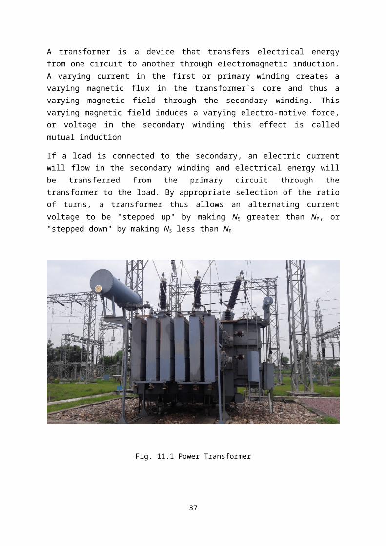
A transformer is a device that transfers electrical energy from one circuit to another through electromagnetic induction. A varying current in the first or primary winding creates a varying magnetic flux in the transformer's core and thus a varying magnetic field through the secondary winding. This varying magnetic field induces a varying electro-motive force, or voltage in the secondary winding this effect is called mutual induction
If a load is connected to the secondary, an electric current will flow in the secondary winding and electrical energy will be transferred from the primary circuit through the transformer to the load. By appropriate selection of the ratio of turns, a transformer thus allows an alternating current voltage to be "stepped up" by making NS greater than NP, or "stepped down" by making NS less than NP
Fig. 11.1 Power Transformer
28

11.2 MAIN PARTS OF POWER TRANSFORMER
11.2.1 WINDING
Winding shall be of electrolytic grade copper free from scales & burrs. Windings shall be made in dust proof and conditioned atmosphere. Coils shall be insulated that impulse and power frequency voltage stresses are minimum. Coils assembly shall be suitably supported between adjacent sections by insulating spacers and barriers. Bracing and other insulation used in assembly of the winding shall be arranged to ensure a free circulation of the oil and to reduce the hot spot of the winding. All windings of the transformers having voltage less than 66 kV shall be fully insulated. Tapping shall be so arranged as to preserve the magnetic balance of the transformer at all voltage ratio. All leads from the windings to the terminal board and bushing shall be rigidly supported to prevent injury from vibration short circuit stresses.
11.2.2 TANK AND FITTING
Tank shall be of welded construction & fabricated from tested quality low carbon steel of adequate thickness. After completion of welding, all joints shall be subjected to dye penetration testing. At least two adequately sized inspection openings one at each end of the tank shall be provided for easy access to bushing & earth connections. Turrets & other parts surrounding the conductor of individual phase shall be non-magnetic. The main tank body including tap changing compartment, radiators shall be capable of withstanding full vacuum.
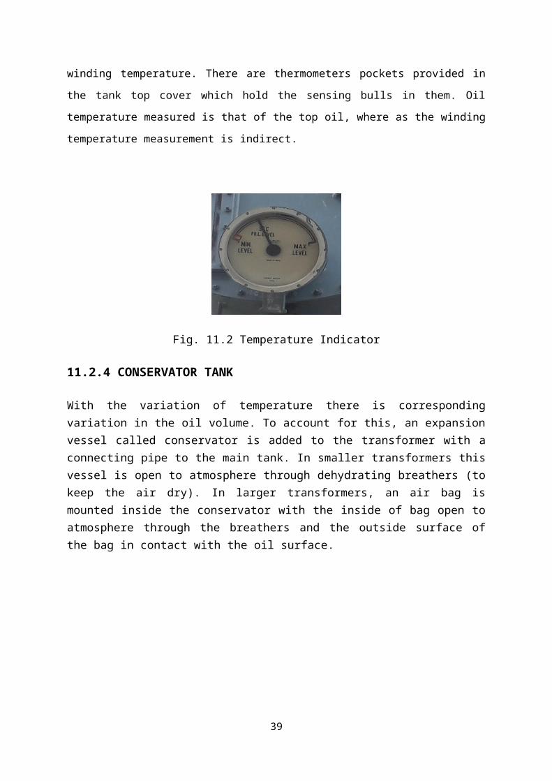
11.2.3 TEMPERATURE INDICATOR
Most of the transformer (small transformers have only OTI) are provided with indicators that
displace oil temperature and winding temperature. There are thermometers pockets provided in
the tank top cover which hold the sensing bulls in them. Oil temperature measured is that of the
top oil, where as the winding temperature measurement is indirect.
Fig. 11.2 Temperature Indicator
29

11.2.4 CONSERVATOR TANK
With the variation of temperature there is corresponding variation in the oil volume. To account for this, an expansion vessel called conservator is added to the transformer with a connecting pipe to the main tank. In smaller transformers this vessel is open to atmosphere through dehydrating breathers (to keep the air dry). In larger transformers, an air bag is mounted inside the conservator with the inside of bag open to atmosphere through the breathers and the outside surface of the bag in contact with the oil surface.
Fig. 11.3 Conservator Tank
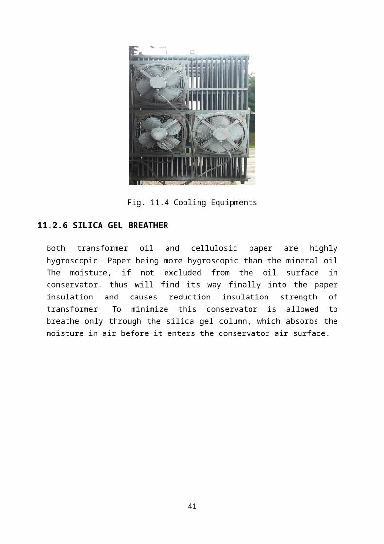
11.2.5 COOLING EQUIPMENTS
Cooling equipment shall conform to the requirement stipulated below: 1. Each radiator bank shall have its own cooling fans, shut off valves at the top and bottom (80mm size) lifting lugs, top and bottom oil filling valves, air release plug at the top, a drain and sampling valve and thermometer pocket fitted with captive screw cap on the inlet and outlet. 2. Cooling fans shall not be directly mounted on radiator bank which may cause undue
vibration. These shall be located so as to prevent ingress of rain water. Each fan shall be
suitably protected by galvanized wire guard.
30

Fig. 11.4 Cooling Equipments
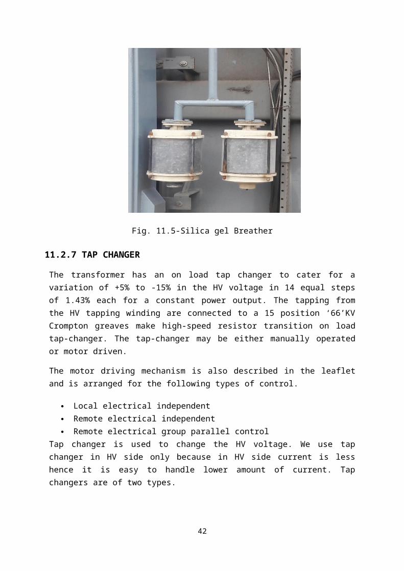
11.2.6 SILICA GEL BREATHER
Both transformer oil and cellulosic paper are highly hygroscopic. Paper being more hygroscopic than the mineral oil The moisture, if not excluded from the oil surface in conservator, thus will find its way finally into the paper insulation and causes reduction insulation strength of transformer. To minimize this conservator is allowed to breathe only through the silica gel column, which absorbs the moisture in air before it enters the conservator air surface.
Fig. 11.5-Silica gel Breather
31
11.2.7 TAP CHANGER
The transformer has an on load tap changer to cater for a variation of +5% to -15% in the HV voltage in 14 equal steps of 1.43% each for a constant power output. The tapping from the HV tapping winding are connected to a 15 position ‘66’KV Crompton greaves make high-speed resistor transition on load tap-changer. The tap-changer may be either manually operated or motor driven.
The motor driving mechanism is also described in the leaflet and is arranged for the following types of control.
Local electrical independent Remote electrical independent Remote electrical group parallel control
Tap changer is used to change the HV voltage. We use tap changer in HV side only because in HV side current is less hence it is easy to handle lower amount of current. Tap changers are of two types.
1. No Load Tap changer:-In this type tap-changer, we have to cut off load before changing the taps. These kinds of tap changer are used in small transformers only.
2. On Load tap changer:-In this type tap-changer load remains connected to transformer while changing the taps. This kind of tap-changer requires special construction. Tapping winding is placed over HV winding. Generally, tapping winding is divided in 6 parts by the combination of these 6 winding and HV winding 17 different tap positions are used.
Fig. 11.6 Tap changer
32

CHAPTER-12
RELAY
12.1 INTRODUCTION
A relay is an electrically operated switch. Current flowing through the coil of the relay creates a magnetic field which attracts a lever and changes the switch contacts. The coil current can be on or off so relays have two switch positions and they are double throw (changeover) switches.
Relays allow one circuit to switch a second circuit which can be completely separate from the first. For example a low voltage battery circuit can use a relay to switch a 230V AC mains circuit. There is no electrical connection inside the relay between the two circuits, the link is magnetic and mechanical.
The coil of a relay passes a relatively large current, typically 30mA for a 12V relay, but it can be as much as 100mA for relays designed to operate from lower voltages. Most ICs (chips) cannot provide this current and a transistor is usually used to amplify the small IC current to the larger value required for the relay coil The maximum output current for the popular 555 timer IC is 200mA so these devices can supply relay coils directly without amplification.
Relays are usually SPDT or DPDT but they can have many more sets of switch contacts, for example relays with 4 sets of changeover contacts are readily available.
12.2 TYPE OF RELAY
These are called normally opened, normally closed in GSS control room. There is panel in which the relays are set and there are many types of relays
12.2.1 OVER VOLTAGE RELAY
This protection is required to avoid damage of system in case line becomes open circuited at one end These fault would trip the local circuit breaker thus block the local and remote ends This relay is operated i e , energized by CVT connected to lines.
12.2.2 OVER CURRENT RELAY
This relay has the upper electromagnet of non-directional relay connected in series with lower non-directional electromagnet When the fault current flow through relay current coil which produces flux in lower magnet of directional element. Thus the directional relay has the winding over the electromagnets of non-directional element and produces a flux in lower magnet and thus over current operates.
33
12.2.3 EARTH FAULT RELAY
When a conductor breaks due to some reason and it is earthen then earth fault occurs. The fault current is very high thus, there is need to of over current relay this relay has minimum operating time.
12.2.4 DIRECTIONAL RELAY
It allows flow the current only in one direction then only this relay operates. It has a winding connected through the voltage coil of relay to lower magnet winding called current coil Which is energized by C T if fault occurs This relay operates when v/I is less than theoretical value The V/I is normally constant.
12.2.5 DIFFERENTIAL RELAY
This relay operates when phase difference of two electrical quantities exceeds the predetermined value. It has always two electrical quantities; hence, in 400KV GSS for transformer differential relay is used.
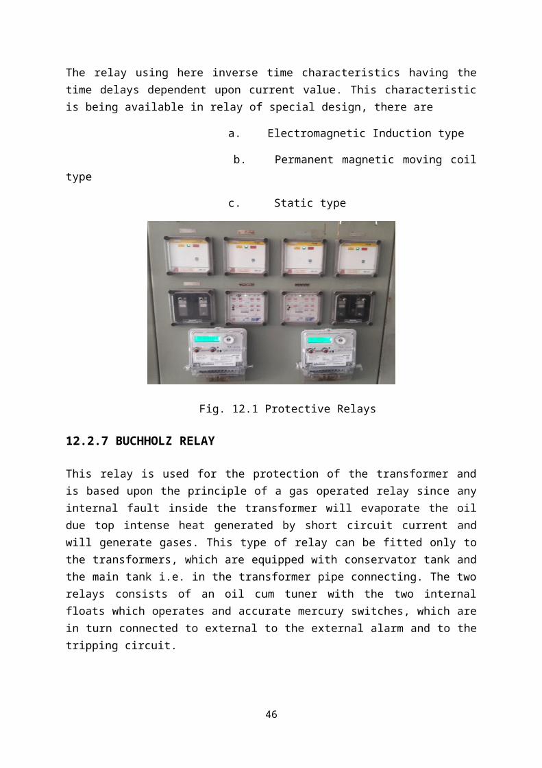
12.2.6 INVERSE TIME CHARACTERISTICS RELAY
The relay using here inverse time characteristics having the time delays dependent upon current value. This characteristic is being available in relay of special design, there are
a. Electromagnetic Induction type
b. Permanent magnetic moving coil type
c. Static type
Fig. 12.1 Protective Relays
34

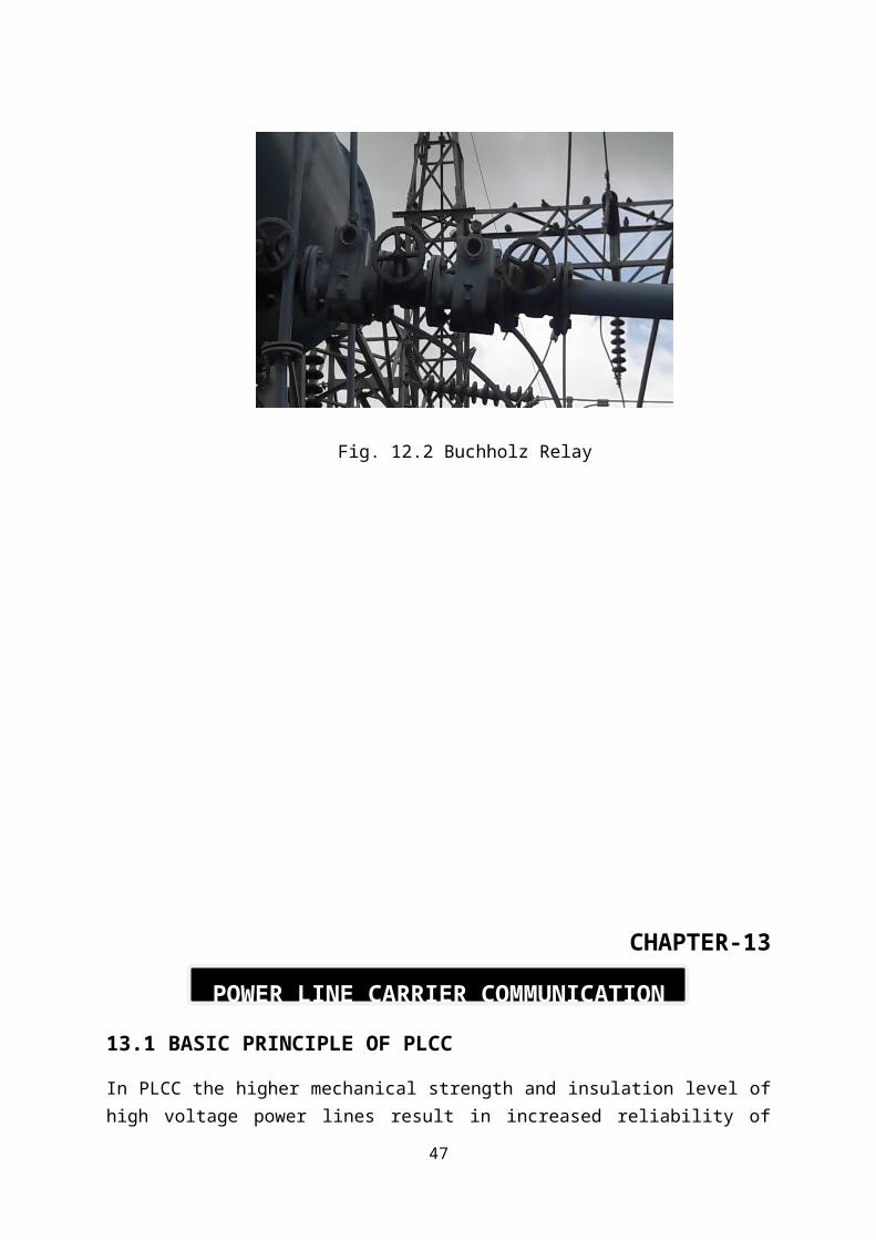
12.2.7 BUCHHOLZ RELAY
This relay is used for the protection of the transformer and is based upon the principle of a gas operated relay since any internal fault inside the transformer will evaporate the oil due top intense heat generated by short circuit current and will generate gases. This type of relay can be fitted only to the transformers, which are equipped with conservator tank and the main tank i.e. in the transformer pipe connecting. The two relays consists of an oil cum tuner with the two internal floats which operates and accurate mercury switches, which are in turn connected to external to the external alarm and to the tripping circuit.
Fig. 12.2 Buchholz Relay
35
CHAPTER-13
POWER LINE CARRIER COMMUNICATION
13.1 BASIC PRINCIPLE OF PLCC
In PLCC the higher mechanical strength and insulation level of high voltage power lines result in increased reliability of communication and lower attenuation over long distances. Since telephone communication system cannot be directly connected to the high voltage lines, suitably designed coupling devices have therefore to be employed. These usually consist of high voltage capacitor with potential devices used in conjunction with suitable line matching units(LMU’s) for matching the impedance of line to that of the coaxial cable connecting the unit to the PLC transmit-receive equipment. Also the carrier currents used for communication have to be prevented from entering the power equipment used in GSS as this would result in high attenuation or even complete loss of communication signals when earthed at isolator. To prevent this loss, wave traps or line traps are employed. These consist of suitably designed choke coils connected in series with line, which offers negligible impedance to RF carrier current. As electronics plays a vital role in the industrial growth, communication is also a backbone of any power station, communication between various generating and receiving station is very essential for proper operation of power system. This is more so in case of a large interconnected system where a control lead dispatch station has to coordinate the working of various units to see that the system is maintained in the optimum working condition, power line communication is the most economical and reliable method of communication for medium and long distance in power network.
13.2 COMPONENT OF COUPLING ARRANGEMENT
1. Wave Trap.2. Coupling Capacitor.3. Drainage coil.4. Voltage arrestor.5. Ground switch.6. Matching transformer.7. Tuning capacitor.8. Vacuum arrestor.
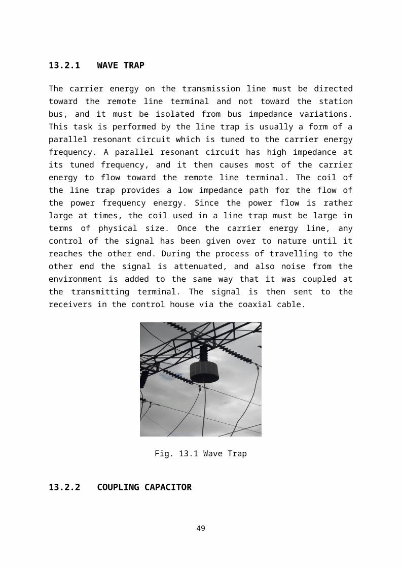
13.2.1 WAVE TRAP
The carrier energy on the transmission line must be directed toward the remote line terminal and not toward the station bus, and it must be isolated from bus impedance variations. This task is performed by the line trap is usually a form of a parallel resonant circuit which is tuned to the carrier energy frequency. A parallel resonant circuit has high impedance at its tuned frequency, and it then causes most of the carrier energy to flow toward the remote line
36
terminal. The coil of the line trap provides a low impedance path for the flow of the power frequency energy. Since the power flow is rather large at times, the coil used in a line trap must be large in terms of physical size. Once the carrier energy line, any control of the signal has been given over to nature until it reaches the other end. During the process of travelling to the other end the signal is attenuated, and also noise from the environment is added to the same way that it was coupled at the transmitting terminal. The signal is then sent to the receivers in the control house via the coaxial cable.
Fig. 13.1 Wave Trap
13.2.2 COUPLING CAPACITOR
The coupling capacitor is used as part of the tuning circuit. The capacitor is a device which provides low impedance path for the carrier energy to the high voltage line and at the same time, it blocks the power frequency current by being a high impedance path at those frequencies. It can perform its function of dropping line voltage across its capacitance if the low voltage end is at ground potential. Since it is desirable to connect the line tuner output to for the carrier signal and low impedance path for the power frequency current. This device is an inductor and it is called a drain coil. The coupling capacitor and drain coil circuit are shown in diagram.
Fig. 13.2 Coupling Capacitor and Drain Coil Combination
37

13.2.3 DRAINAGE COIL
The drainage coil has a pondered iron core that serves to ground the power frequency charging to appear in the output of the unit. The coarse voltage arrester consists of an air gap, which sparks over at about 2 kV and protects the matching units against line surge. The grounding switch is kept open during normal operation and is closed if anything is to be done on the communication equipment without interruption to power flow on the line. The LMU which consist of the matching transformer and tuning capacitors indicated above is tailor-made to suit the individual requirements of the coupling equipment and is generally tuned to a wide band of carrier frequencies (100-450 kHz typical).
13.3 ADVANTAGES AND DISADVANTAGES OF PLCC
ADVANTAGES
1. No separate wires are needed for communication purposes as the power lines themselves carry power as well as the communication signals. Hence the cost of constructing separate telephone lines is saved.
2. When compared with ordinary lines the power lines have appreciably higher mechanical strength. They would normally remain unaffected under the condition which might seriously damage telephone lines.
3. Power lines usually provide the shortest route between the power stations.4. Power lines have large cross-sectional area resulting in very low resisntanc3 per unit
length. Consequently the carrier signal suffers lesser attenuation than when travel on usual telephone lines of equal lengths.
5. Power lines are well insulated to provide negligible leakage between conductors and ground even in adverse weather conditions.
6. Largest spacing between conductors reduces capacitance which results in smaller attenuation at high frequencies. The large spacing also reduces the cross talk to a considerable extent.
DISADVANTAGES
1. Proper care has to be taken to guard carrier equipment and persons using them against high voltage and currents on the line.
2. Reflections are produced on spur lines connected to high voltage lines. This increases attenuation and create other problems.
3. High voltage lines have transformer connections, which attenuate carrier currents. Sub-station equipments adversely affect the carrier currents.
4. Noise introduced by power lines is much more than in case of telephone lines. This due to the noise generated by discharge across insulators, corona and switching processes.
38
CHAPTER-14
CONTROL ROOM
14.1 INTRODUCTION
Control panels contain meters, control switches and recorders located in the control building, also called a doghouse. These are used to control the substation equipment, to send power from one circuit to another or to open or to shut down circuits when needed
Fig. 14.1 Substation control panel
14.2 SYNCHRONIZING PANEL
There is a hinged panel mounted on the end of a control board to take out new supply. On bus bar we have the synchronies and fee the synchronoscope zero on this bus bar. The voltage can be checked by voltmeter the function of synchronoscope is to indicate phase and frequently voltage of bus bar and incoming feeder voltage of bus bar and incoming feeder voltage supply.
14.3 SYNCHRONOSCOPE
A synchronoscope is used to determine the correct instance of closing the switch with connect the new supply to bus bar the correct instance of synchronizing is indicated when bus bar and incoming voltage.
39

1. Are equal in magnitude2. Are equal in phase3. Have the same frequency.4. The phase sequence is same.The voltage can be checked by voltmeter the function of synchronoscope is to indicate phase and frequently voltage of bus bar and incoming feeder voltage of bus bar and incoming feeder voltage supply.
14.4 ANNUNCIATOR
In the control room the Annunciator the most compact in which probable faults at different feeders and different feeders and different zone have written to inform the bulb behind the structure when some faults is annunciator auxiliary relay. Relay’s first signal trip the circuit breaker and signal goes to the auxiliary trip the relay, the relay send the signal to the annunciator which give alarm and bulb is lighting up in front of the type of fault occurred.
14.5 MEASURING INSTRUMENT USED
7. ENERGY METER: To measure the energy transmitted energy meters are fitted to the panel to different feeders the energy transmitted is recorded after one hour regularly for it MWH meter is provided.
8. WATTMETERS: Wattmeter’s are attached to each feeder to record the power exported form GSS.
9. FREQUENCY METER: To measure the frequency at each feeder there is the provision of analog or digital frequency meter.
10. VOLTMETER: It is provided to measure the phase-to-phase voltage. It is also available in both the forms analog as well as digital.
11. KA METER: It is provided to measure the line current. It is also available in both the forms analog as well as digital.
12. MAXIMUM DEMAND INDICATOR: These are also mounted on the control panel to record the average power over successive predetermined period.
13. MVAR METER: It is to measure the reactive power of the circuit.
14. COSФ METERS: To indicate the power factor of the power being transferred or imported. These meters are provided on various panels.
40
CHAPTER-15
BATTERY ROOM
15.1 INTRODUCTION
In a GSS, separate dc supply is maintained for signalling remote position control, alarm circuit etc. Direct current can be obtained from 220volt 3 phase ac supply via rectifier and in event of arc failure, from the fixed batteries, which are kept, charged in normal condition by rectifier supply.
15.2 BATTERY SYSTEM
The batteries used are lead acid type having a solution of sulfuric acid and distilled water as electrolytes. In charged state, it has a specific gravity of 1.2 at temperature of 30 0C. In the battery room batteries are mounted on wooden stand .The cells are installed stand by porcelain.
Figure 15.1 Battery Room
41
CHAPTER-16
CAPACITOR BANK
16.1 INTRODUCTION
Capacitor banks are used to improve the quality of the electrical supply and the efficient
operation of the power system. Studies show that a flat voltage profile on the system can
significantly reduce line losses. Capacitor banks are relatively inexpensive and can be easily
installed anywhere on the network.
Fig. 16.1 Capacitor Bank
The capacitor unit is made up of individual capacitor elements, arranged in parallel/ series
connected groups, within a steel enclosure. The internal discharge device is a resistor that
reduces the unit residual voltage to 50V or less in 5 min. Capacitor units are available in a
variety of voltage ratings (240 V to 24940V) and sizes (2.5 KVAR to about 1000 KVAR).
Capacitor bank used for 33 KV at GSS has 2 units of 7.2 MVAR.
42

CHAPTER 17EARTHING OF THE SYSTEM
17.1 INTRODUCTION
The provision of an earthing system for an electric system is necessary by the following reason.
1. In the event of over voltage on the system due to lightning discharge or other system fault. These part of equipment which are normally dead as for as voltage, are concerned do not attain dangerously high potential.
2. In a three phase, circuit the neutral of the system is earthed in order to stabilize the potential of circuit with respect to earth.
The resistance of earthing system is depending on1. Shape and material of earth electrode used.2. Depth in the soil3. Specific resistance of soil surrounding in the neighbourhood of system electrodes.
17.2 PROCEDURE OF EARTHINGTechnical consideration the current carrying path should have enough capacity to deal with more fault current. The resistance of earth and current path should be low enough to prevent voltage rise between earth and neutral. Main earthling system must be separate from earthing for lightning protection. The earth electrode must be drive ion to the ground to a sufficient depth to as to obtain lower value of earth resistance. To sufficient lowered earth resistance a number of electrodes are inserted in electrode must be drive ion to the ground to a sufficient depth to as to obtain lower value of earth resistance. To sufficient lowered earth resistance a number of electrodes are inserted in the earth to a depth they are connected together to form a mesh.The resistance of earth should be for the mesh in generally inserted in the earth at 0.5m depth the several point of mesh then connected to earth electrode or ground connection. The earth electrode is metal plate copper is used for Earth plate.
17.2.1 GROUNDING OF LINE STRUCTURE
High voltage transmission lines are carried out on lattice structure, which are grounded with one or more grounding rods driven vertically at the surface. When earth resistivity is high and driven rod id not adequate the remedy is bury the wire in earth and connect it to the lower footing. The wire may run parallel or at some angle to the time conductor is called as counter poise.
43
Fig. 17.1 Ground Wire
17.2.2 OVERHEAD SHIELDING WIRE
These wires are supported on the top of substation structure each top is connected to earthing system by galvanized iron earthing strips, cover entire switchyard.
17.2.3 NEUTRAL EARTHING
Neutral earthing of power transformer all power system operates with grounded neutral. Grounding of neutral offers several advantages the neutral point of generator transformer is connected to earth directly or through a reactance in some cases the neutral points is earthed through is adjustable reactor of reactance matched with the line. The earthing is one of the most important features of system design for switchgear protection neutral grounding is important because:
1. The earth fault protection is based on the method of neutral earthing.2. The neutral earthing is associated switch gear.3. The neutral earthing is provided for the purpose of protection arcing ground Sun
balanced voltages with respect to protection from lightning and for improvement of system.
MERITS OF NEUTRAL EARTHING
1. Arcing grounding is reduced.2. Voltage of heating with respect to earth remains at harmless value they don’t
increase to root 3 times of the normal value.3. The life of insulation is long due to prevention of voltage surges or sustained over
voltage.4. Suitable neutral point.5. The earth fault relaying is relatively simple useful amount of earth fault current is
available to operate earth fault relay.6. The over voltage due to lightning are discharged to earth.7. By employing resistance reactance in earth connection the earth fault can be
controlled.
44

CHAPTER-18
RATINGS
18.1 TRANSFORMERTotal No. of transformers = 3 No. of transformers
132/33 KV---------------------------------------20/25 MVA 1
132/33 KV---------------------------------------10/12.5 MVA 1
33/.415 KV-------------------------------------- 250 KVA 1
MAKE Company
132/33 KV, 20/25 MVA----------------------------------ECE INDUSTRIES LTD
132/33 KV, 10/12.5 MVA------------------------------- BHARAT BIJLEE LTD
33/.415 KV, 250KVA ---------------------------------- DENISH LTD
18.2 CIRCUIT BREAKERNo. of 132KV breaker - 5
No. of 33KV breaker - 10
No. of Capacitor Bank (33kv)- 2
18.2.1 SF6 CIRCUIT BREAKER
BREAKER SERIAL NUMBER 101297
RATED VOLTAGE 145 KV
NORMAL CURRENT 1250 A
FREQUENCY 5OHz
LIGHTNING IMPULSE WITHSTAND VOLTAGE 650 KVP
SHORT TIME WITHSTAND CURRENT 40KA
DURATION OF SHORT CIRCUIT 3 Sec
SHORT CIRCUIT BREAKING CURRENT 40 KA
SHORT CIRCUIT MAKING CURRENT 100 KAP
SF6 GAS PRESSURE AT 200C 0.74 MPa(abs)
TOTAL MASS OF CB 1534 Kg
45
TOTAL MASS OF SF6 GAS 12 Kg
YEAR OF MANUFACTURE 2007
18.2.2 VACUUM CIRCUIT BREAKER
SERIAL NUMBER 20205 VP
CIRCUIT BREAKER TYPE 36PV25A
RATED VOLTAGE 36 KV
RATED CURRENT 1250 AMP
FREQUENCY 50 Hz
NO. OF POLES 3
SHUNT TRIP 110 V DC
BREAKING CAPACITY 25 KA
MAKING CAPACITY 62.5 KApk
SHORT TIME CURRENT 25 KA
SHORT TIME DURATION 3 Sec
MANUFACTURE YEAR 2008
18.3 CURRENT TRANSFORMER:FREQUENCY 50 Hz
HIGHEST SYSTEM VOLTAGE 145 KV
SHORT TIME CURRENT 40 KA
RATED CURRENT 600 A
CURRENT RATIO 125-250-500/1A
18.4 CAPACITIVE VOLTAGE TRANSFORMER:SERIAL NUMBER 1207345
TYPE CVE-145/650/50
INSULATION LEVEL 460KV
RATED VOLTAGE FACTOR 1.2/Cont
TIME 1.5/30 Sec
HIGHEST SYSTEM VOLTAGE 145KV
PRIMARY VOLTAGE 132KV/1.732KV
SECONDARY VOLTAGE 33KV/1.732KV
46
FREQUENCY 50 Hz
WEIGHT 850 Kg
YEAR OF MANUFACTURE 2007
18.5 BATTERY CHARGERSERIAL NUMBER 2K71004
MAKE RECLETRON
RATED VOLTAGE 123.5 V
RATED CURRENT 30 A
YEAR OF MANUFACTURE 2007
47

CONCLUSION
It was a very good experience of taking summer training at 132KV GSS BHADOTI, SAWAI
MADHOPUR (RAJ.). All the Employees working there were very helpful and were always
ready to guide me. They gave their best to make us understand.
Training at 132 KV GSS BHADOTI, SAWAI MADHOPUR (RAJ.) gives the insight of the real instruments used. There are many instruments like transformer, CT, PT, CVT, LA, relay, PLCC, bus bars, capacitor bank, insulator, isolators, control room, Battery room etc. What is the various problem seen in substation while handling this instruments. There are various occasion when relay operate and circuit breaker open, load shedding, shut down, which has been heard previously.To get insight of the substation, how things operate, how things manage all is learned there. Practical training as a whole proved to be extremely informative and experience building and the things learnt at it would definitely help a lot in snapping the future ahead a better way.
48
REFERENCE
1. Power System Protection And Switchgear By BADRI RAM
2. Power System Engineering By J. NAGRATH and D.P. KOTHARI
3. Electrical Machine By ASHFAQ HUSAIN
4. http://electricalpowerengineering.blogspot.in
5. http://www.electrical4u.com/
6. http://en.wikipedia.org/wiki/Insulator_(electricity)
7. http://www.engineersgarage.com/articles/plcc-power-line-carrier-communication\
8. GSS MANUAL
49