A Thrown Together Sheet Metal Finger Brake - … · June 2, 2010 Page 1 of 12 R.G. Sparber A Thrown...
12
June 2, 2010 Page 1 of 12 R.G. Sparber A Thrown Together Sheet Metal Finger Brake By R.G. Sparber Copyleft protects this document 1 . Background A few weeks ago I attended our monthly Valley Metal Club 2 meeting. As usual, I was treated with an inspiring presentation about something new to me. In this case, it was Bill Townsend and Bret Chilcott talking about sheet metal bending. I was so inspired that I wanted to go out and buy a “3 in 1 sheet metal machine 3 ” at Harbor Freight. Part of the talk was how to remanufacture this machine so it actually works well. Since Harbor Freight was near the meeting site, I decided to drop in and see what they were talking about. Besides the price, I was stopped by the size and weight of the machine. I would have to get rid of a machine or two in order to make room. It was time to start thinking about “plan B”: making my own finger brake. Most of the time, I enjoy making things with a fair amount of precision. This time I decided to see if I could make a usable machine with minimal planning and precision. 1 You may freely copy and distribute this document but please do not modify it. 2 The club is based in and around Phoenix, AZ. See http://www.valley-metal.org/ 3 See http://www.harborfreight.com/30-inch-shear-press-brake-and-slip-roll-5907.html
Transcript of A Thrown Together Sheet Metal Finger Brake - … · June 2, 2010 Page 1 of 12 R.G. Sparber A Thrown...

June 2, 2010 Page 1 of 12 R.G. Sparber
A Thrown Together Sheet Metal Finger
Brake
By R.G. Sparber
Copyleft protects this document1.
Background
A few weeks ago I attended our monthly Valley Metal Club2 meeting. As usual, I
was treated with an inspiring presentation about something new to me. In this
case, it was Bill Townsend and Bret Chilcott talking about sheet metal bending. I
was so inspired that I wanted to go out and buy a “3 in 1 sheet metal machine3” at
Harbor Freight. Part of the talk was how to remanufacture this machine so it
actually works well. Since Harbor Freight was near the meeting site, I decided to
drop in and see what they were talking about. Besides the price, I was stopped by
the size and weight of the machine. I would have to get rid of a machine or two in
order to make room. It was time to start thinking about “plan B”: making my own
finger brake.
Most of the time, I enjoy making things with a fair amount of precision. This time I
decided to see if I could make a usable machine with minimal planning and
precision.
1 You may freely copy and distribute this document but please do not modify it.
2 The club is based in and around Phoenix, AZ. See http://www.valley-metal.org/
3 See http://www.harborfreight.com/30-inch-shear-press-brake-and-slip-roll-5907.html

June 2, 2010 Page 2 of 12 R.G. Sparber
The finished Machine
The brake is built from a length of 3/16” thick 3” x 3” angle which I found on the
side of the road a few years ago. The handle came from a steel fence I wrecked
out last year. All other bits were from my junk pile. No fasteners were used in this
design. Although I do have a very nice stick welder that would be appropriate for
this thickness of steel, I wanted to see if I could get away with my Harbor Freight
MIG welder because it is so easy to set up and use.

June 2, 2010 Page 3 of 12 R.G. Sparber
I cut the fingers from a plate of ½” steel pulled from a scrap yard. It was bent but I
was able to cut a 3” wide strip from it that was flat. You can’t see it from this
angle, but the back ends of these fingers were flame cut. The guy was in a big
hurry. It may not look so good, but it will have no effect on how the brake works.
My plan is to clamp one or more of these fingers down on the brake to bend any
width from ½” up to 8½” in steps of ½”.
Focusing on What is Important
This brake cannot be completely slapped together. Two things have to be right.
For starters, the two pieces of angle must be on the same plane when the brake is
open. This is easy to do by clamping both angles to the same flat plate.
The second critical element is the hinge. If it is not set true, the movable part of
the brake will bind up.
Alignment of the hinge was
accomplished by putting the movable
part of the table in my mill vise and
machining a notch in each end that
was 0.250” wide and 0.250” deep.
June 2, 2010 Page 4 of 12 R.G. Sparber
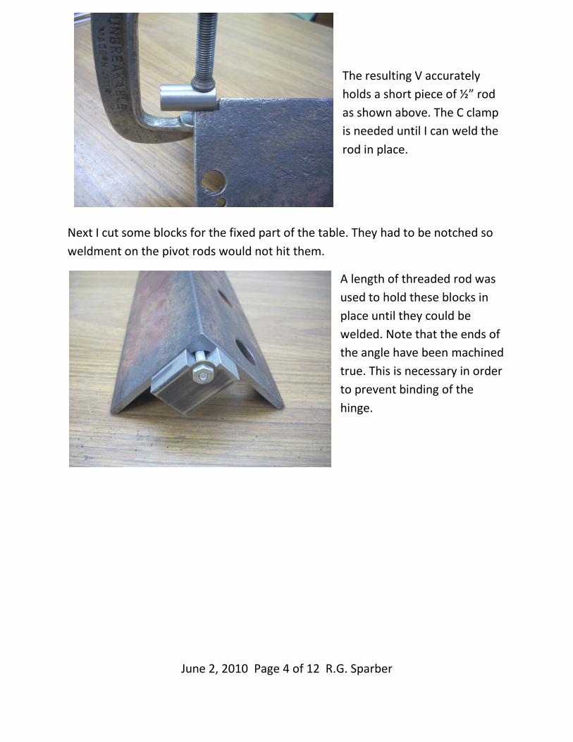
The resulting V accurately
holds a short piece of ½” rod
as shown above. The C clamp
is needed until I can weld the
rod in place.
Next I cut some blocks for the fixed part of the table. They had to be notched so
weldment on the pivot rods would not hit them.
A length of threaded rod was
used to hold these blocks in
place until they could be
welded. Note that the ends of
the angle have been machined
true. This is necessary in order
to prevent binding of the
hinge.

June 2, 2010 Page 5 of 12 R.G. Sparber
Here is a close up of the second hinge. I thought
I had figured the width correctly but discovered
that an additional ¼” of width was needed on
the fixed part of the table. Not a problem – just
tacked on a scrap of steel.
Now, we have the pivot pins aligned with the
movable part of the table and pads ready to
accept the pivot arms. I then took two blocks of
steel and drilled the two holes a bit under ½”. I then reamed them to ½”. The pins
are a nice sliding fit. It is just a matter of welding the two together. No binding.
Here is the finished brake. A small
block has been welded to the
vertical part of the fixed table. The
block is held in my bench vise so
there is no need to make a support
for it.

June 2, 2010 Page 6 of 12 R.G. Sparber
Machining the Fingers
The next step was to make the fingers. I set my angle table to about 20° and then
milled a bevel. Here you see the cut about half way through. I’m using 3 clamps
but still don’t feel that this is strong enough for serious hogging. Instead I took
only 0.05” per pass. Sure it took a while but at least it stayed put. I moved the
front clamp as needed to let the cutter pass. I was unable to mill all the way to the
right end due to limitations in my X axis. I could have removed my vise and had
room to shift the assembly over but that seemed like a lot of work.

June 2, 2010 Page 7 of 12 R.G. Sparber
Here I am slicing up the beveled plate into fingers. You can see the flame cut edge
of the plate. The block of paraffin wax is placed such that the blade cuts it before
entering the plate. The wax works well as a cutting lubricant and doesn’t make
the mess of oil. As each finger is cut, I cleaned it up on my belt sander.
I started by cutting the ½” wide finger and then moved on to the wider fingers. In
this way I didn’t end up trying to clamp a short length of plate in order to cut the
½” finger. Instead the last cut was the 4” wide finger which was easy to clamp.

June 2, 2010 Page 8 of 12 R.G. Sparber
Time to try out the finger brake.
I have clamped a square to the fixed table. To its left is my ½” wide finger which is
holding down a strip of ½” sheet metal. The finger is back from the pivot line by
the thickness of that stainless steel plate that you see all the way to the left.
I lifted the movable table and now have my
first 90° bend. Note that I have avoided a fancy
finger clamp. I plan to just clamp each finger
individually.

June 2, 2010 Page 9 of 12 R.G. Sparber

June 2, 2010 Page 10 of 12 R.G. Sparber
Not bad for a first try.
I was going to add a section on the theory of bending sheet metal but found an
excellent article in Wikipedia:
http://en.wikipedia.org/wiki/Bending_%28metalworking%29
The key thing to realize is that the finger clamping the sheet metal is defining one
tangent of an arc that will be created as you lift the movable table. As the arc is
formed, it draws material from the unclamped sheet metal. The surface of the
movable table defines the second tangent of this arc. This is all spelled out nicely
under the heading of Bending Allowance in the above article.

June 2, 2010 Page 11 of 12 R.G. Sparber
My First Real Project
One of the things made at the club meeting was a fastener sorting tray. I really
liked the idea so decided to try and make one.
The inside of this tray is 5” so I used my 1” and 4” fingers for those bends. The
open space flanking these fingers is room for the adjacent sides of the tray. One
source for more information on how to use a finger brake is YouTube.com. Just
search for “finger brake metal bending”.
The diagonal crease was formed on my small vise
mounted V brake.

June 2, 2010 Page 12 of 12 R.G. Sparber
Conclusion
Using scrap metal and very little planning, I have built a serviceable small finger
brake. Alignment was accomplished primarily by milling two “V”s in the movable
table and all other parts referenced them. The result is a pivot that does not bind.
I can bend any width from ½” to 8½” in ½” steps. Maybe now I can stop buying
small project boxes and make my own.
Acknowledgements
I wish to thank Bill Townsend and Bret Chilcott for opening my eyes to sheet
metal bending. Thanks to my faithful friend Larry Gill who is one tough editor.
Rick Sparber