A theoretical and practical treatise on the strength of beams and columns (1889)
197
Transcript of A theoretical and practical treatise on the strength of beams and columns (1889)

8/14/2019 A theoretical and practical treatise on the strength of beams and columns (1889)
http://slidepdf.com/reader/full/a-theoretical-and-practical-treatise-on-the-strength-of-beams-and-columns-1889 1/196
8/14/2019 A theoretical and practical treatise on the strength of beams and columns (1889)
http://slidepdf.com/reader/full/a-theoretical-and-practical-treatise-on-the-strength-of-beams-and-columns-1889 2/196
T
REESE LIBRARYOF THE
UNIVERSITY OF CALIFORNIA.
Received^ ^L
Accessions No. *$-&-<r-^--3 Shelf No.
8/14/2019 A theoretical and practical treatise on the strength of beams and columns (1889)
http://slidepdf.com/reader/full/a-theoretical-and-practical-treatise-on-the-strength-of-beams-and-columns-1889 3/196

8/14/2019 A theoretical and practical treatise on the strength of beams and columns (1889)
http://slidepdf.com/reader/full/a-theoretical-and-practical-treatise-on-the-strength-of-beams-and-columns-1889 4/196

8/14/2019 A theoretical and practical treatise on the strength of beams and columns (1889)
http://slidepdf.com/reader/full/a-theoretical-and-practical-treatise-on-the-strength-of-beams-and-columns-1889 5/196

8/14/2019 A theoretical and practical treatise on the strength of beams and columns (1889)
http://slidepdf.com/reader/full/a-theoretical-and-practical-treatise-on-the-strength-of-beams-and-columns-1889 6/196

8/14/2019 A theoretical and practical treatise on the strength of beams and columns (1889)
http://slidepdf.com/reader/full/a-theoretical-and-practical-treatise-on-the-strength-of-beams-and-columns-1889 7/196

8/14/2019 A theoretical and practical treatise on the strength of beams and columns (1889)
http://slidepdf.com/reader/full/a-theoretical-and-practical-treatise-on-the-strength-of-beams-and-columns-1889 8/196
8/14/2019 A theoretical and practical treatise on the strength of beams and columns (1889)
http://slidepdf.com/reader/full/a-theoretical-and-practical-treatise-on-the-strength-of-beams-and-columns-1889 9/196

8/14/2019 A theoretical and practical treatise on the strength of beams and columns (1889)
http://slidepdf.com/reader/full/a-theoretical-and-practical-treatise-on-the-strength-of-beams-and-columns-1889 10/196

8/14/2019 A theoretical and practical treatise on the strength of beams and columns (1889)
http://slidepdf.com/reader/full/a-theoretical-and-practical-treatise-on-the-strength-of-beams-and-columns-1889 11/196
INTRODUCTION.
FOK more than two centuries the mathematical and me-
chanical laws that govern the transverse strength of Beams andColumns have received the attention of the most expert
mathematicians of all countries. Galileo, in 1038, formulated
and published the first theory on the subject. He was fol-
lowed by such philosophers as Mariotte, Leibnitz, Bernoulli ,
Coulomb, and others, each amending and extending the work
of his predecessor, until the year 1824, when Navier succinctly
statedthe theory
that is
recognizedto be correct at the
present
day, and to which subsequent writers and investigators have
added but little.
This theory has neither received the endorsement of the
experimenters nor of some of the theoretical writers. * Ex-
cepting as exhibiting approximately the laws of the phenom-
ena, the theory of the strength of materials has many prac-
tical defects (Wiesbach). It has long been known that under
the existing theory of beams, which recognizes only two ele-
ments of strength namely, the resistance to direct compression
and extension the strength of a bar of iron subjected to a
transverse strain cannot be reconciled with the results obtained
from experiments on direct tension, if the neutral axis is in
the centre of the bar (Barlow).
During the present century much time and means have
been expended in attempts to solve, experimentally, the prob-
lems that have engaged the attention of the mathematicians,
and as the result of their labors we find such experimenters as
Hodgkinson, Fairbairn, and others, whose names are house-

8/14/2019 A theoretical and practical treatise on the strength of beams and columns (1889)
http://slidepdf.com/reader/full/a-theoretical-and-practical-treatise-on-the-strength-of-beams-and-columns-1889 12/196
IV INTRODUCTION
hold words in the literature of the subject, adopting empirical
rules for the
strength
of .Beams and Columns rather than the
rational formulas deduced by the scientists. For no theory
of the rupture of a simple beam has yet been proposed which
fully satisfies the critical experimenter'- (De Yolson Wood).That we should be able to deduce the strength of Beams and
Columns from the known tensile and compressive strength of
the material composing them, has been apparent to manywriters and experimenters on the subject, but to the present
time no theory has been advanced that embodies the mathe-
matical and mechanical principles necessary to its accomplish-
ment. The theory herein advanced and the formulas resulting
therefrom deduce the strength of Beams and Columns from
the direct crushing and tensile strength of the material com-
posing them, without the aid of that coefficient that has no
place in nature, the Modulus of Rupture. The theory and
the formulas deduced therefrom are in strict accord with cor-
rect mechanical and mathematical principles, and the writer
believes that they will fully satisfy the results obtained by the
experimenter.
The great practical benefits to be derived from the correct
theory of the strength of Beams and Columns will be evident,
when we consider the countless tons of metal that have
been made into railroadrails, rolled beams, and the other
various shapes, and that the manufacturers were without
knowledge of the work to be performed by the different parts
of the beam or column insustaining the load that it was in-
tended to carry. The best that they have been able to do is
to compute the strength by the aid of an empirical quantitydeduced from experiments on
similar beams. The correct
theory will enable them to foretell the strength of any untried
shape, and the reason for the strength of those that have been
long in use, which is the true object of theory.
E. II. C.
DALLAS, TEXAS, March 13, 1889.
8/14/2019 A theoretical and practical treatise on the strength of beams and columns (1889)
http://slidepdf.com/reader/full/a-theoretical-and-practical-treatise-on-the-strength-of-beams-and-columns-1889 13/196
CONTENTS.
CHAPTER I.
FORCES DEFINED AND CLASSED.
ART.PAGE
1. Force Defined, 1
2. Stress or Strain, ......... 1
3. The Load, 2
4. Equilibrium and Resultant. ....*... 2
5. Bending Moment Concentrated Forces, ..... 3
6. General Formulas for Bending Moments, .... 6
7. Uniformly Varying Forces Rectangular Areas, ... 8
8. Resultant, 8
9. Moment of
Uniformly VaryingForces, . . .
*
9
10. 11
11. Uniformly Varying Forces Circular Segment Areas, , . 13
12. Moment of Uniformly Varying Forces Circular Segment Areas, 13
13. '
' 14
14. Resultant, *
16
15. Moment of Uniformly Varying Forces Circular Arcs, . . 17
16. '.'
V
18
17. Resultant,
1-9
CHAPTER II.
RESISTANCE OF CROSS SECTIONS TO RUPTURE.
18. Moment of Resistance, 21
19. Neutral Line, 21
20. Bending JL and Moment of Resistance, . 22
21. Equilibrium, 23
22. Position of the Neutral Line 24
23. Neutral Line at the Transverse Elastic Limit,
....24
24. Movement of the Neutral Line, with the Deflection, . . 26
25. Neutral Lines of Rupture in a Rectangular Section, ... 28
26. Relative Value of the Coinpressive and Tensile Strains, 28
27. Summary of the Theory,31

8/14/2019 A theoretical and practical treatise on the strength of beams and columns (1889)
http://slidepdf.com/reader/full/a-theoretical-and-practical-treatise-on-the-strength-of-beams-and-columns-1889 14/196
VI CONTENTS.
CHAPTER Til.
TRANSVERSE STRENGTH.ART. PAGE
28. Coefficients of Strength, 33
29. Elasticity of Materials, . . . ... . . .3330. Elastic Limits, 34
31. Elastic Limit of Beams, 34
32. Working Load and Factors of Safety, 34
33. General Formula Transverse Strength, . .. :'.. . .3534. Relative Transverse Strength of a Beam, 35
35. Moment of Resistance Rectangular Sections,
....37
36. The Neutral Line .... 38
37. Transverse Strength .... 38
38. Designing a Beam .... 39
39. To Compute the Compressive Strain, 39
39.
Tensile 39
40. Moment of Resistance Hodgkinson Sections, . . . .4041. Neutral Line
. . ... 42
42. Transverse Strength .... 44
43. To Design a Hodgkinson Section, 44
44. Moment of Resistance Dbl. T and Hollow Rectangular Sections, 47
45. Neutral Line '-'.' 4$
46. Transverse Strength <
4#
47. To Design a '
<
48
48. Moment of Resistance Invtd T, Dbl. Invtd. T and U Sections, 52
49. Neutral Line 53
50. Transverse Strength 53
51. To Design an 53
52. Moment of Resistance Circular Sections, 55
53. Neutral Line 56
54. Transverse Strength
56
55. To Compute the Compressive Strain of Circular Sections, . 58
56.
Tensile,
. . 58
57. Relative Strength of Circular and Square Sections, . . . 59
58. Moment of Resistance Hollow Circular Sections, . . .6059. Neutral Line
60
60. Transverse Strength
60
CHAPTER IV.
CAST-IRON BEAMS.
61. Compressive Strength of Cast-Iron, . 64
62. Tensile
64

8/14/2019 A theoretical and practical treatise on the strength of beams and columns (1889)
http://slidepdf.com/reader/full/a-theoretical-and-practical-treatise-on-the-strength-of-beams-and-columns-1889 15/196
CONTENTS. Vll
ART. PAGE
63. Ratio of the Compressive to the Tensile Strength, ... 65
64. Transverse Strength of Cast-Iron,
65
65. To Compute the Compressive Strength of Cast-iron, . . 67
65.
Tensile ... 67
66. Neutral Line Rectangular Cast-Iron Beams, .... 71
67. Transverse Strength ' .... 71
68. To Design a Rectangular Cast-iron Beam, .... 73
69. Hodgkinson Beams, . . . . . . . .7470. Mr. Hodgkinson 's Experiments, ...... 74
71. Neutral Line Hodgkinson Cast-iron Beams, . . . .7572. Transverse Strength
75
73. To Design a Hodgkinson Cast-Iron Beam, 78
74. Neutral Line Double T and Box Cast-Iron Beams, . . 78
75. Transverse Strength
. . .7876. To Design a Double T and Box Cast-iron Beam, . . . 79
77. Neutral Line Cast-Iron Circular Beams, 80
78. Transverse Strength .... 81
79. Movement of the Neutral Line 82
80. Relative Strength of Circular and Square Cast-Iron Beams, . 83
81. Neutral Line Hollow Circular Cast Iron Beams,. .
.8582. Transverse Strength
' ... 86
CHAPTER V.
WIIOUGHT-IRON AND STEEL BEAMS.
83. Compressive Strength of Wrought-Iron, . . 87
84. Tensile. .
87
85. Compressive
Steel 88
86. Tensile
. 88
87. To Compute Compressive Strength of Wrought-Iron and Steel, 88
88.
Tensile
90
89. Transverse Strength of Wrought-Iron Beams, . . . .9190.
Steel Beams, 92
91. Neutral Line Rectangular Wrought-Iron and Steel Beams, . 92
92. Transverse Strength
. 92
93. Neutral Line Wrt. Iron and St'l Dbl. T and Rolled Eye-Beams, 96
94. Transverse Strength . 96
95. TransverseStrength Wrought-Iron
and Steel Double T Beams,
Flanges Unequal 96
96. Transverse Strength Wrought-Iron and Steel Double T Beams,
Flanges Equal, . 98
97. Neutral Line Circular Wrought-Iron and Steel Beams, . . 100
98. Transverse Strength ... .101
8/14/2019 A theoretical and practical treatise on the strength of beams and columns (1889)
http://slidepdf.com/reader/full/a-theoretical-and-practical-treatise-on-the-strength-of-beams-and-columns-1889 16/196
Vlll CONTENTS.
ART. PAGE
99. Neutral Line Hollow Circular Wrought-Iron Steel Beams, . 104
100. Transverse Strength . 104
CHAPTER VI.
TIMBEIl BEAMS.
101. The Compress ve and Tensile Strength of Timber, . . .106
102. To Compute the Compressive and Tensile Strength of Timber, 106
103. Neutral Line Rectangular Wooden Beams, .... 107
104. Transverse Strength .... 108
105. Neutral Line Circular . ... .111106. Transverse Strength
.
. . . . 112
107. Relative Strength of Square and Circular Timber Beams, . . 113
CHAPTER VII.
STRENGTH OF COLUMNS.
108. General Conditions of Failure of Columns, . . . . 114
109. Resistance of the Cross-Section of the Column, . . . .119
110. Notation, 121
111. Deflection of Columns, 121
112. Classification of Columns, ....... 123
113. Columns that fail with the full Crushing Strength of the Material, 125
114. Columns that fail with less than the full Crushing Strength of
the Material and without Deflection, 125
115. Columns that fail with less than the full Crushing Strength of the
Material and with Deflection, . . . . . . .127
116. Columns that Cross-break from Compression, . . . 130
117. Columns that Cross-break from Compression and Cantileverage, 137
CHAPTER VIII.
COMBINED BEAMS AND COLUMNS.
118. General Statement, 145
119. Notation, 146
INCLINED BEAMS.
120. General Conditions 147
121. Inclined Beam Fixed and Supported at one end, . . . 148
CASE I. When the Load is applied at the free end of the Beam.
CASE II. When the Load is uniformly distributed over the un-
supported length of the Beam. /

8/14/2019 A theoretical and practical treatise on the strength of beams and columns (1889)
http://slidepdf.com/reader/full/a-theoretical-and-practical-treatise-on-the-strength-of-beams-and-columns-1889 17/196
CONTENTS. IX
ART. PAGE
122. Inclined Beam supported at one end and stayed or held in po-
sition at the other without verticalsupport,
....151
CASE I. When the Inclined Beam is loaded at its stayed end.
CASE II. Wlien the Inclined Beam is loaded at its middle.
CASE III. When the Load is uniformly distributed over the
length of the Inclined Beam.
CASE IV. When the Inclined Beam is loaded at its middle, and
with an additional Load at its stayed end.
CASE V. When tlie Load is uniformly distributed over the length
of the Inclined Beam, and an additional Load applied to its
123. Inclined Beam supported vertically at both ends and loaded at
its middle, 160
124. Inclined Beam supported at both erids and the Load uniformly
distributed over its length, 163
TRUSSED BEAMS.
125. General Conditions, 164
Note. The writer regrets that chapters on the following subjects are un-
avoidably omitted at this time, The Strength of Arches and The De-
flection of Beams, as they were not satisfactorily complete, and ''Byamsof Maximum Strength with Minimum Material, as he was not fully pro-
tected by letters-patent at the time of going to press.
8/14/2019 A theoretical and practical treatise on the strength of beams and columns (1889)
http://slidepdf.com/reader/full/a-theoretical-and-practical-treatise-on-the-strength-of-beams-and-columns-1889 18/196

8/14/2019 A theoretical and practical treatise on the strength of beams and columns (1889)
http://slidepdf.com/reader/full/a-theoretical-and-practical-treatise-on-the-strength-of-beams-and-columns-1889 19/196

8/14/2019 A theoretical and practical treatise on the strength of beams and columns (1889)
http://slidepdf.com/reader/full/a-theoretical-and-practical-treatise-on-the-strength-of-beams-and-columns-1889 20/196
2 STRENGTH OF BEAMS AND COLUMNS.
the contiguous parts of a body are caused to move away from
each other.
3. The Load. The external forces applied to a body to
produce the various kinds of stress or'
strain is called the
Load, and its amount or magnitude is expressed in pounds ;it
may be classed as follows :
Concentrated Forces or Loads. While in nature every force
must be distributed over a definite amount of surface, it is
necessary, in order to define certain principles, to consider
them to be concentrated at a single point, the effect being
identical with that of the distributed load.
A Distributed Force of uniform intensity is the force or
load that acts with the same intensity on each square inch of
the surface of the body over which it is distributed.
A Distributed Force of uniformly varying intensity is a
force that increases in intensity in direct proportion to the
distance from a given point.
4. Equilibrium and Resultant. Equilibrium of a
system of forces is such a condition that the combined action
of the forces produces no change in the rest or motion of the
body to which it is applied.
The Resultant of a system of forces is a single concen-
trated force that will produce the same effect upon the body,
if applied, that the system of forces will produce.

8/14/2019 A theoretical and practical treatise on the strength of beams and columns (1889)
http://slidepdf.com/reader/full/a-theoretical-and-practical-treatise-on-the-strength-of-beams-and-columns-1889 21/196
CONCENTRATED PARALLEL
SECTION II. Concentrated Parallel Forces.
5. Bending Moment. In this section will be deduced
the relation existing between the vertical forces caused by
gravity, the supporting forces and the horizontal distances
between their lines of action. In order to ascertain the rela-
tion between such forces it is necessary to obtain the product
of each force by the perpendicular distance of its line of
action fromagiven point. Such product
is called theBending
Moment of the force.
The vertical forces will be called the loads, and the connec-
tion between their lines of action will be called a beam, with-
out reference to the shape of its cross-section, its material, or
its ability to resist the bending moment of the applied loads,
which will be considered in the sequel.
The following notation will be used throughout :
Z = the total applied load in pounds.
,9 = the span, the horizontal distance between the supports
in inches.
M = the bending moment. *
Case I. THE BEAM FIXED AT ONE END AND LOADED AT THE
OTHER.
A load thus applied will bend the beam (Fig. 1) at each
section from the free end to the point of support, but un-
equally. The bending moment at any section is the product of-

8/14/2019 A theoretical and practical treatise on the strength of beams and columns (1889)
http://slidepdf.com/reader/full/a-theoretical-and-practical-treatise-on-the-strength-of-beams-and-columns-1889 22/196
4 STRENGTH OF BEAMS AND COLUMNS.
the load by the distance of the section from the. free end of
the beam. The Greatest Bending Moment, at the point of
support, will be
GBM = L >< *.(1)
Case II. THE BEAM FIXED AT ONE END AND THE LOAD
UNIFORMLY DISTRIBUTED OVER THE ENTIRE SPAN.
The fending moment at any section is equal to the product
of the load between the free end of the beam and the section
by one half of its distance from the free end ; the Greatest
Bending Moment, at the point of support, will be
or one half what it is in CaseI., the load, Z, and the span, s,
being the same.
Case III. THE BEAM SUPPORTED AT THE ENDS AND THE
LOAD APPLIED AT THE MIDDLE OF THE SPAN.
In order that equilibrium shall exist one half of the load
must be supported by each point of support ;the load will
bend the beam (Fig. 2) in the same manner that it would if
the beam were fixed in the middle of its span and loaded at
each free end with one half of the applied load, L ;the lend-
ing moment at any section will be one half of the load
multiplied by its distance from the nearest point of support ;
8/14/2019 A theoretical and practical treatise on the strength of beams and columns (1889)
http://slidepdf.com/reader/full/a-theoretical-and-practical-treatise-on-the-strength-of-beams-and-columns-1889 23/196
CONCENTRATED PARALLEL FORCES. 5
the Greatest Bending Moment, at the middle of the span, will
be
Jj 8 -Li X S /o\:T, X 77
=3
, (3)
or onefourth of that in Case L, and one half that in Case II.,
the load and span being the same in each.
Case IV. THE BEAM SUPPORTED AT THE ENDS AND THE
LOAD, Z, UNIFORMLY DISTRIBUTED OVER THE SPAN.
The Greatest Bending Moment occurs at the middle of the
span,
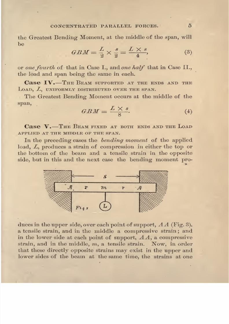
Case V. THE BEAM FIXED AT BOTH ENDS AND THE LOAD
APPLIED AT THE MIDDLE OF THE SPAN.
In the preceding cases the bending moment of the applied
load, Z, produces a strain of compression in either the top or
the bottom of the beam and a tensile strain in the opposite
side, but in this and the next case the bending moment pro-
duces in the upper side, over each point of support, AA (Fig. 3),
a tensilestrain,
and in the middle a
compressivestrain
;and
in the lower side at each point of support, AA, a compressive
strain, and in the middle, m, a tensile strain. Now, in order
that these directly opposite strains may exist in the upper and
lower sides of the beam at the same time, the strains at one
8/14/2019 A theoretical and practical treatise on the strength of beams and columns (1889)
http://slidepdf.com/reader/full/a-theoretical-and-practical-treatise-on-the-strength-of-beams-and-columns-1889 24/196
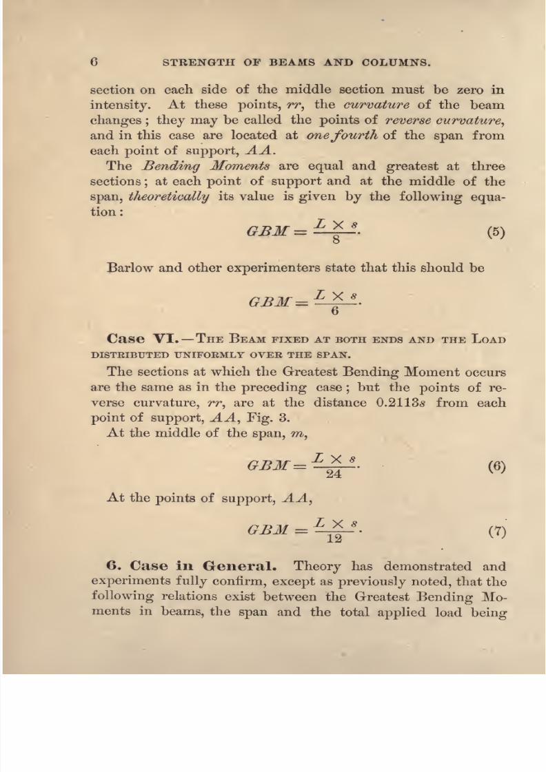
6 STRENGTH OP BEAMS AND COLUMNS.
section on each side of the middle section must be zero in
intensity.
At thesepoints, rr,
the curvature of the beam
changes ; they may be called the points of reverse curvature,
and in this case are located at onefourth of the span from
each point of support, AA.
The Sending Moments are equal and greatest at three
sections;at each point of support and at the middle of the
span, theoretically its value is given by the following equa-
tion:
Barlow and other experimenters state that this should be
GBM= L **.
D
Case VI. THE BEAM FIXED AT BOTH ENDS AND THE LOAD
DISTRIBUTED UNIFORMLY OVER THE SPAN.
The sections at which the Greatest Bending Moment occurs
are the same as in the preceding case;but the points of re-
verse curvature, rr, are at the distance 0.2113s from each
point of support, AA, Fig. 3.
At the middle of the span, m,
.
(6)
At the points of support, AA,
GBM = ^p- (7)
6. Case in General. Theory has demonstrated and
experiments fully confirm, except as previously noted, that the
following relations exist between the Greatest Bending Mo-
ments in beams, the span and the total applied load being
8/14/2019 A theoretical and practical treatise on the strength of beams and columns (1889)
http://slidepdf.com/reader/full/a-theoretical-and-practical-treatise-on-the-strength-of-beams-and-columns-1889 25/196
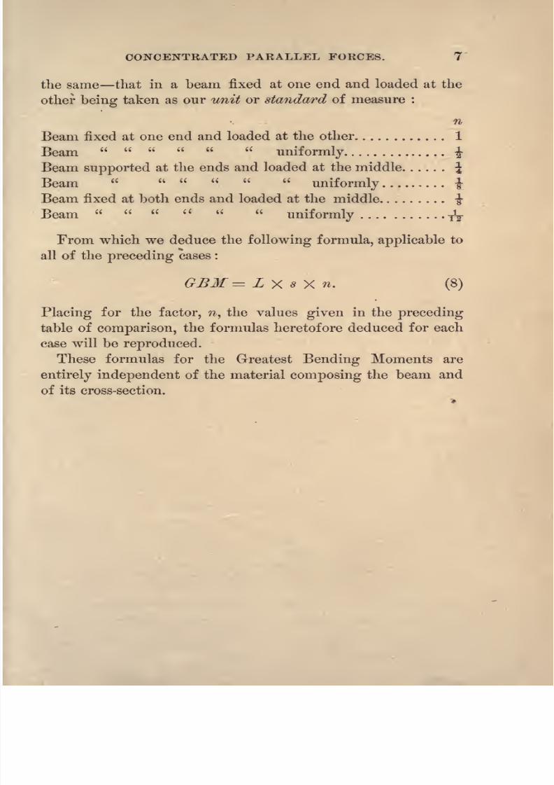
CONCENTRATED PARALLEL FORCES. 7
the same that in a beam fixed at one end and loaded at the
other being taken as our unit or standard of measure :
n
Beam fixed at one end and loaded at the other 1
Beam uniformly %
Beam supported at the ends and loaded at the middle J
Beam uniformly i
Beam fixed at both ends and loaded at the middle-J-
Beam uniformly TV
From which we deduce the following formula, applicable to
all of the preceding cases :
GSM = L X * X n. (8)
Placing for the factor, n, the values given in the preceding
table of comparison, the formulas heretofore deduced for each
case will be reproduced.
These formulas for the Greatest Bending Moments are
entirely independent of the material composing the beam and
of its cross-section.

8/14/2019 A theoretical and practical treatise on the strength of beams and columns (1889)
http://slidepdf.com/reader/full/a-theoretical-and-practical-treatise-on-the-strength-of-beams-and-columns-1889 26/196
8 STRENGTH OF BEAMS AND COLUMNS.
SECTION III. Uniformly Varying Forces RectangularAreas.-
7. Notation. The principles governing the action of
uniformly varying forces distributed over rectangular surfaces
will be deduced, and then those applicable to surfaces bounded
by curved lines will be considered. In order to determine the
effect of such a force, we must determine the resultant, its
point of application, its lever-arm, and from these the momentof the uniformly varying force. The following notation will
be used, and it will have the same meaning whenever it appears
in the following pages :
C the maximum compressive strain, in pounds, per square
inch.
T = the maximum tensile strain, in pounds, pel* square inch.
7?T = the moment of the tensile strain in inch-pounds.
7?c= the
compressive strain in inch-pounds.
dv =: the depth of the area covered by the compressive strain
in inches.
r/T= the depth of the area covered by the tensile strain in
inches.
d = dc -\- dT= the total depth of the area in inches.
I)
= the total width of the area in inches.
8. Resultant. The amount of direct strain is equal to
T
T
A
the weight of a prismoidal wedge composed of such material
that a prism an inch square in section and C or T high will

8/14/2019 A theoretical and practical treatise on the strength of beams and columns (1889)
http://slidepdf.com/reader/full/a-theoretical-and-practical-treatise-on-the-strength-of-beams-and-columns-1889 27/196
UNIFORMLY VARYING FORCES. 9
give a pressure on its base equal to C or T as defined above;
the resultant will then be equal to the product of the depth
r/c or d^ by the width5, by one half of the height C or T, whieli
is the volume of the wedge, and it will pass through a point
at-f the depth dc or dT from the edge of the wedge J., of
which Fig. 4 is a section.
7, ,MTT MCC
. . Resultant = - - or ^ (9)
Lever-arm =^
or -^-'
By the Calculus :
Let XT = dT = AB, the depth of the area,
x any distance from A,
Tx- = the height of the wedge at x, distance from A,
bdx = a small area, or the differential,
Ta? , Tbx*=JQ v
-
2^'
. . ResultantT
>
/#r
7^2 Tbx3
bdx = ,
*T 3^T
.
*
. The moment ?.
o
Dividing the moment by the resultant we obtain the lever arm = fdr.
9. Problem I. REQUIRED THE MOMENT OF AN UNIFORMLY
VARYING COMPRESSIVE FOKCE OF MAXIMUM INTENSITY, C\ WITH
RESPECT TO AN AXIS, J3, IN THE BACK OF THE PRESSURE WEDGE.
Let ABD (Fig. 5) represent a section through the pressure
wedge.MC
The resultant = 7^ >

8/14/2019 A theoretical and practical treatise on the strength of beams and columns (1889)
http://slidepdf.com/reader/full/a-theoretical-and-practical-treatise-on-the-strength-of-beams-and-columns-1889 28/196

8/14/2019 A theoretical and practical treatise on the strength of beams and columns (1889)
http://slidepdf.com/reader/full/a-theoretical-and-practical-treatise-on-the-strength-of-beams-and-columns-1889 29/196
UNIFORMLY VARYING FORCES.
By the Calculus :
Let xc= dc
= the depth AB (Fig. 5),
x = any distance from A,
C= the intensity of the force at the depth xt
bdx = a small area of the base of the wedge,
11
-.JLsBSp.otli.'lt
Integrating the above expression for Rc ,between the limits x = dc and
x = di, we obtain
Ec
b
jj~ (Me-
2di) C, or Eq. 12.
1O. Problem III. REQUIRED THE MOMENT, 7?T, OF AN
UNIFORMLY VARYING TENSILE FORCE, WITH RESPECT TO AN AXIS,
0, PARALLEL TO THE EDGE, A, OF THE TENSION WEDGE, AND AtTHE DISTANCE OA = d
c FROM IT.
T
Let ABD (Fig. 6) represent a section through the tension
wedge.
- = the resultant,a
df, -f- fdT =. its lever-arm,
or. (13)

8/14/2019 A theoretical and practical treatise on the strength of beams and columns (1889)
http://slidepdf.com/reader/full/a-theoretical-and-practical-treatise-on-the-strength-of-beams-and-columns-1889 30/196
12 STRENGTH OF BEAMS AND COLUMNS.
PROBLEM IV. Required the moment of only a part of the
above force distributed over the depth EB = d2 and the
width ~bv
Consider the force to be divided into two portions. The
first, with the intensity at E constant over the distance EB;
the second increasing inintensity from zero at G to
-j-T
T
at F.
d^ ( 1 --jT = the intensity of the force at E^
{ d --] = its lever-arm,
-yT= the intensity of the force at
.Z?,less that E^
ttj,
f 6?
2
J = its lever-arm.
By adding the moments we obtain
~ ~
By the Calculus :
Let x-t = t?T = the distance AB,
x = any distance from A,
xT= the intensity of the force at any distance x,
(de -\-x)= its lever-arm,
bdx = the differential of the area of the base,
bdr. . BT
= __(2d 4- de) T, or Eq. 13.
o
Integrating the above expression for I&, between the limits x = dr
and x = di, and placing 5 2 for b, we have

8/14/2019 A theoretical and practical treatise on the strength of beams and columns (1889)
http://slidepdf.com/reader/full/a-theoretical-and-practical-treatise-on-the-strength-of-beams-and-columns-1889 31/196

8/14/2019 A theoretical and practical treatise on the strength of beams and columns (1889)
http://slidepdf.com/reader/full/a-theoretical-and-practical-treatise-on-the-strength-of-beams-and-columns-1889 32/196
14 STRENGTH OF BEAMS AND COLUMNS.
Let r the radius of the circle,
d = dc
+<#T
= tne diameter,a?
c= dc
= the versine of one half the arc MEN,x = any distance from the axis 02?$,
x*~ X
-- O the intensity of the pressure at any distance,XQ
x, from the axis OB8,
2 (Zrx x^dx = the differential of the area of the base,
.-.EQ= X
i/O
Integrating, we obtain
Substituting the following equalities :
_I /V|
71 versin. one half of the arc of the segment MBN
reducing, we obtain
f1r~ ~i
7^c=
24^c ^^T [4rf
2
c(^-r)+ r>(30?'-14rfc)] +Ci?wp.rc (12c?e
-lor)
l2
<H&
from which the moment of any compressed wedge may be
computed. The factor Comp. Arc is the arc MEN.
13. Problem. REQUIRED THE MOMENT OF AN UNIFORMLY
VARYING TENSILE FORCE, DISTRIBUTED OVER THE SEGMENT OF A
CIRCLE, WITH RESPECT TO AN AXIS THAT IS A TANGENT TO THE
CIRCLE, PARALLEL TO THE EDGE OF THE TENSION WEDGE, AND AT
THE DISTANCE dc FROM IT.
Let, in Fig. 8, FOS represent the axis, MNB the base of
the tension wedge, MN the edge, and OABD a section
through OB.

8/14/2019 A theoretical and practical treatise on the strength of beams and columns (1889)
http://slidepdf.com/reader/full/a-theoretical-and-practical-treatise-on-the-strength-of-beams-and-columns-1889 33/196
UNIFORMLY VARYING FORCES. 15
O
B
Let XT
dT the distance
AB,x = any distance from B toward A.
#T x j1
the intensity of the force at any distance a?T a?
a?T
from A.,
d x =. its lever-arm.
2 (2rx a?3
)*<&c = the differential of the area of the base of
the wedge.
For notation, refer to Arts. 7 and 12.
= /Xfe-
12 24: 24
9/-
Substituting the following values :
rversin. = one half the tension arcr
reducing, we obtain

8/14/2019 A theoretical and practical treatise on the strength of beams and columns (1889)
http://slidepdf.com/reader/full/a-theoretical-and-practical-treatise-on-the-strength-of-beams-and-columns-1889 34/196
16 STRENGTH OF BEAMS AND COLUMNS.
Fig.3
3?< - *)+ 18r
('r -
-f-Tension arc 9r)r
2
)I n
6)
from which the required moment maybe computed.
14. Problem. REQUIRED THE RE-
SULTANT OR AMOUNT OF DIRECT FORCE OF
AN UNIFORMLY VARYING FORCE DISTRIB-
UTED OVER A CIRCULAR SEGMENT AREA.
Let Fig. 9 represent the pressure
wedge, MBN the base or circular seg-
ment, and B the origin of co-ordinates.
Let XG= AB the versine of one half of the arc MBN,
x = any distance from the origin B,
2 (2rx a?2
)dx the differential of the segment,
V =. the resultant or volume of the pressure wedge,
O= the greatest height, DB,
=Jo
Substituting the equalities given in Art. 12 and reducing, we
have
r r ~
-f- Segment arc (dc r)3r
The resultant of a tension force
maybe obtained from the
above equation by placing T for C.
The cubic contents of any cylindrical wedge may be com-
puted from Eq. 17 by substituting for C\ expressed in pounds,
h, the greatest height of the wedge in inches.

8/14/2019 A theoretical and practical treatise on the strength of beams and columns (1889)
http://slidepdf.com/reader/full/a-theoretical-and-practical-treatise-on-the-strength-of-beams-and-columns-1889 35/196
UNIFORMLY VARYING FORCES. 17
The area of the base of the pressure wedge or that of any
segment
of a circle
maybe
computed
from the
following
:
Area = 2 \/dcd^ (^cr) + Segment arc
X^->
in which
dc= versine of one half the arc of the segment,
r = the radius,
d? = the diameter, less dc .
(VIA)
SECTION ^. Uniformly Varying Forces Circular
Arcs.
15. Problem. REQUIRED THE MOMENT OF AN UNIFORMLY
VARYING COMPRESSIVE FORCE DISTRIBUTED OVER THE ARC OF A
CIRCLE, WITH RESPECT TO AN AXIS THAT IS A TANGENT TO THE
CIRCLE AND PARALLEL TO THE CHORD JOINING THE EXTREMI-
TIES OF THE ARC.
Let, in Fig. 10, OBS represent the axis, MEN the arc/
ABD a section through AB, B the origin of co-ordinates,
C the intensity of the force at B, and zero that at M and N.
Fig10
For notation refer to Arts. 7 and 12.
Let xc= dc
= the versine AB of one half the arc
x = any variable distance from B or the axis,

8/14/2019 A theoretical and practical treatise on the strength of beams and columns (1889)
http://slidepdf.com/reader/full/a-theoretical-and-practical-treatise-on-the-strength-of-beams-and-columns-1889 36/196
18 STRENGTH OF BEAMS AND COLUMNS.
^n? C = the intensity of the force at x distance,
r = the radius of the circle,
- = twice the differential of the arc,
E -= r**^rdx -
JO ^%rx _ g? X,
Integrating, we obtain
Jie = 2C r - r
Substituting the values given in Art. 12, we have
rV(18)
16. Problem. REQUIRED THE MOMENT OF AN UNIFORMLY
VARYING FORCE DISTRIBUTED OVER THE ARC OF A CIRCLE, WITH
RESPECT TO AN AXIS THAT IS A TANGENT TO THE CIRCLE, PARAL-
LEL TO THE CHORD CONNECTING THE EXTREMITIES OF THE ARC,
AND AT THE DISTANCE dcFROM IT.
Let, in Fig. 11, FOS represent the axis, MBN the arc,
T
OABD a section through OB, T the intensity of the force at
BS and zero at M and N.

8/14/2019 A theoretical and practical treatise on the strength of beams and columns (1889)
http://slidepdf.com/reader/full/a-theoretical-and-practical-treatise-on-the-strength-of-beams-and-columns-1889 37/196
UNIFORMLY VARYING FORCES. 19
For notation refer to Arts. 7 and 12.
Let #T= dT
= the versine of one half the arc
MBN,x = any distance from the origin B,
g'
T~ x T the intensity of the force at any distance
a?,
#T
d x its lever-arm,
Zrdx. the differential of the arc.
V'Zrx X*
~
Integrating, we obtain
B*=5 [
4/^ [2 (r + 4)] + Tension arc (2//i~
from which the required moment may be computed.
17. Problem. REQUIRED THE RESULTANT OR AMOUNT OF
DIRECT FORCE OF AN UNIFORMLY VARYING FORCE DISTRIBUTED
OVER AN ARC OF A CIRCLE.
Let, in Fig. 9, page 16, MBN represent the arc of the circle,
1&NBD a wedge whose cylindrical surface is equal to the re-
quired resultant, the force being C in intensity at B and zero
at M and N.
Let xc
dc= the distance AB,
x any distance from the origin of co-ordinates J?,
a?c
x,_^ intensity of the force at the point a?,
arc>
V= the resultant or volume of the pressure wedge,
V=

8/14/2019 A theoretical and practical treatise on the strength of beams and columns (1889)
http://slidepdf.com/reader/full/a-theoretical-and-practical-treatise-on-the-strength-of-beams-and-columns-1889 38/196
20 STRENGTH OF BEAMS AND COLUMNS.
.'-.; F= fir VdA + Segment arc (d-
/)],(20)
from which the required resultant may be computed.
The curved surface of a cylindrical wedge may be com-
puted from the above formula by substituting for(7, expressed
in pounds, A, the greatest height of the wedge in inches.

8/14/2019 A theoretical and practical treatise on the strength of beams and columns (1889)
http://slidepdf.com/reader/full/a-theoretical-and-practical-treatise-on-the-strength-of-beams-and-columns-1889 39/196
CHAPTER II.
RESISTANCE OF CROSS-SECTIONS TO RUPTURE.
18. Moment of Resistance. The cross-section is
theshape
of thefigure
and the area that
any material,such as
a beam, would show, should it be ,cut into two pieces by a
plane perpendicular to its length, and its resistance to rupture
at this plane or section is the number of inch-pounds that its
fibres will offer to forces tending to cross-break the beam or
material of which it is a section : this is called the Moment of
Resistance of the cross-section.
The Moment of Resistance varies in amount with the
material and the shape of the cross-section, but it is entirely
independent of the length of the beam and of the manner in
which the load may be applied, in each case;the same cross-
section and material will offer the same number of inch-bounds
of resistance when broken across. #
19. Neutral Line. When a beam is broken across, or
is acted
upon byforces that bend or tend to break
it,we know
from observation that its fibres on the lower or convex side,
AB (Fig. 12), are in a state of tension, and that those on the

8/14/2019 A theoretical and practical treatise on the strength of beams and columns (1889)
http://slidepdf.com/reader/full/a-theoretical-and-practical-treatise-on-the-strength-of-beams-and-columns-1889 40/196
22 STRENGTH OF BEAMS AND COLUMNS.
upper or concave side, CD, are compressed ;but our knowl-
edgeobtained from observation is limited to what takes
placeoil the surface of the beam. We can only know what takes
place within such a beam by reasoning from analogy ;there is
a tensile strain in the lower side of the beam, AB, and just
the reverse character of strain in the upper side, CD. In
order that these two directly opposite strains may exist in the
same beam at the same time, both strains must decrease from
the surface toward a common point within the beam, where
both strains become zero in intensity, and they may be classed
and treated as 'uniformly varying forces.
A line, nl, for the longitudinal section of the beam, or a
plane for the beam, is called the neutral line or line of no
strainy
its position in a beam having a cross-section of a
given shape, at the instant of rupture, depends upon the
material alone, or upon the ratio existing between the 'break-
ing compressive and tensile fibre strains. No line in this plane
lias any of the properties of an axis that are usually assigned
to it by writers on this subject.
2O. Bending Moment and Moment of Resist-
ance. In order to obtain the relation existing between the
Bending Moment of the applied load and the Moment of
Resistance of the cross-sectionof
thebeam,
conceive one
half of the beam, ABCD (Fig. 12), to be removed and the
bent-lever, ogf (Fig. 13), to be substituted forit,
and that the
same cohesion to exist between the fibres of the bent-lever and
those of the beam along the line, fg, that originally existed
between the fibres of the two halves of the beam along the
same line, the bent-lever, however, preserving its distinctive
character of a bent-lever. The applied load, Z, causes the
bent-lever, ogf, and the half of the beam, A gfD, to move
downward in the direction of the lower arrow of the figure,
and the end of the lever, 0, and that of the half of the beam,
D, to revolve around f in the direction of the upper arrows,

8/14/2019 A theoretical and practical treatise on the strength of beams and columns (1889)
http://slidepdf.com/reader/full/a-theoretical-and-practical-treatise-on-the-strength-of-beams-and-columns-1889 41/196

8/14/2019 A theoretical and practical treatise on the strength of beams and columns (1889)
http://slidepdf.com/reader/full/a-theoretical-and-practical-treatise-on-the-strength-of-beams-and-columns-1889 42/196
24 STRENGTH OF BEAMS AND COLUMNS.
compressive fibre strains must be taken or computed with
reference to the fulcrum, f, and in order that equilibrium
shall exist, the Bending Moment of the applied load, Z, must
be equal to the Moment of Resistance, or the sum of the
moments of the tensile and compressive fibre strains, and that
the latter must be equal to each other in magnitude.
22. Position of the Neutral Line. By deducing
general formulas for the moments of the tensile and compres-
sive fibre strain in a cross-section of a given shape, placing
them equal to each other and deducing from the equation so
formed a general formula for either gn or fn, the position of
the neutral line may be found in any section of the same
shape by substituting in the formula its dimensions and any
known values for the tensile and compressive fibre strains.
In sections of an uniform shape, such as the rectangle and
the circle, the depth of the neutral line below the compressed
side of the beam may be obtained by multiplying the depth
of the rectangle and the diameter of the circle by a deter-
mined quantity that is constant for each shape and material;
this constant multiplier being its position when the depth of
the rectangle and diameter of the circle is unity.
But in irregular shaped sections, such as the T, Double T,
Box, Rolled-eyebeam and other shapes, in which the metal is
not continuous from the neutral line to the top and bottom, a
special solution must be made for eacli case to determine the
position of the neutral line from which to compute the
Moment of Resistance of the section. Before beams of this
character are manufactured, an economical position should be
assumed and a sufficient area of metal placed above and
below the neutral line to furnish the required Moment of
Resistance.
23. Neutral Line at the Transverse Elastic
Limit. Our object intesting, to destruction, the strength of
any piece of construction material is to obtain information

8/14/2019 A theoretical and practical treatise on the strength of beams and columns (1889)
http://slidepdf.com/reader/full/a-theoretical-and-practical-treatise-on-the-strength-of-beams-and-columns-1889 43/196
RESISTANCE OF CROSS-SECTIONS TO RUPTURE. 25
that will guide us to a correct knowledge of its use, when
safety to life and property is demanded, whether this destruc-
tion be by means of extension or compression jas we apply
the load in small instalments there are only two points in its
intensity at which we can record the knowledge thus gained
for futureintelligent, comparative use when it has reached
the elastic limit, and when it is sufficiently intense to rupture
or destroy the piece of material tested. When a beam is
broken by a transverse load that has been applied in small
instalments, we have two similar points, the elastic limit load
and the rupturing load, and these are the only points at
which our information can be used to compute the strength
of similar material when used in structures.
We know that in an ordinary beam without a load its com-
pressive and tensile fibre strain is zero, and that the breaking
transverse load produces the breaking compressive and tensile
strain in the fibres.
JSTow,does the transverse elastic limit
load produce the elastic fibre strain limits ? Is the neutral
surface the same as that for rupture ? When the beam is un-
loaded each plane of fibres is a neutral surface as the load
is applied the compressive and tensile strain penetrates the
beam from the top and bottom respectively ; theoretically *we
know they must meet at a common point within the beam at
the instant of rupture, and that this is fully sustained by ex-
periments will be shown in the sequel. Our theory demands
that when the same ratio exists between the tensile and com-
pressive elastic fibre strain limits that does between the ulti-
mate or breaking strains, in order that equilibrium shall exist,
the neutral surfaces must be identical, but the theory does not
require that the transverse elastic limit load shall produce the
elastic fibre strain limits;we can only gain the desired informa-
tion from discussing a numerical example.
The mean compressive and tensile elastic fibre strain limits
for good wrought-iron is C 30000 pounds and T 30000
pounds per square inch. With these strains, from formulas de-

8/14/2019 A theoretical and practical treatise on the strength of beams and columns (1889)
http://slidepdf.com/reader/full/a-theoretical-and-practical-treatise-on-the-strength-of-beams-and-columns-1889 44/196
26 STRENGTH OF BEAMS AND COLUMNS.
duced in the sequel, the centre elastic limit transverse load of
a bar of wrought-ironsix inches
squareand ten feet
spanis
44100 pounds. The centre elastic limit transverse load of a
bar of wrought-iron, one inch square and one foot span, is
2250 pounds, and that of the above beam from the well-
known formula is,
6 X 36 X 2250Load =
j= -
~~i7T~~ 48600 pounds.
From this practical identity of results, as we have only used
average values, and other special tests given in the sequel, we
are authorized to conclude that the transverse elastic limit
load produces the tensile and compressive fibre strain elastic
limits.
24. Movement of the Neutral Line with the De-
flection. Having established the fact that the transverseelastic limit load produces the elastic fibre strain limits and
our theory requires that the elastic limit neutral line and the
neutral line of rupture shall coincide only when their ratios
are the same, but should they be unequal they must occupy
different positions in the sequel it will be shown that where
these ratios are unequal the elastic limit neutral line is situated
between the neutral line of rupture and the bottom or ex-
tended side of the beam, and that as the loading advanced
from the elastic limit load to the rupturing load, the neutral
surface must have moved upward or toward the compressed
surface of the beam.
From the above we conclude that as there was no changein the condition of the loading that could have reversed the
direction in which the neutral line moved from its position at
the elastic limit to that at rupture, the neutral line at the in-
ception of the loading was at the bottom or extended side of
the beam, and that as the loading progressed it moved up-
ward or toward the compressed side of the beam the tension
area, to avoid rupture in its fibres, continues to encroach upon

8/14/2019 A theoretical and practical treatise on the strength of beams and columns (1889)
http://slidepdf.com/reader/full/a-theoretical-and-practical-treatise-on-the-strength-of-beams-and-columns-1889 45/196
RESISTANCE OF CROSS-SECTIONS TO RUPTURE. 27
the compressed area until the rupturing strain is produced in
both thetop
and the bottom of the beam.
The neutral line, at the inception of the loading, being at
the bottom or extended side of the beam, it can only be moved
upward by reason of the deflection and equally with it. If,
from the dimensions of the beam, it should not be able to
deflectsufficiently to move the neutral line to the position
required for equilibrium between moments of resistance of
the ultimate fibrestrains, the true breaking strength will not
be obtained for the beam. When this is the case the observed
breaking load will be too large for wooden, wrought-iron,
steel and tough cast-iron beams, and too small for the more
fractious varieties of material;
for should the cornpressive
strain reach its ultimate limit before the tensile strain an in-
crease of the load will develop a crushing strain in excess of
the true crushing intensity, as is frequently done in crushingshort blocks; the beam will, however, continue to deflect
under these increased loads, and willfinally develop the full
tensile strength, when the beam will be broken by a load
much in excess of its true breaking load.
From the above, the reason for the variation in the modulus
of rupture that is required in the common theory ef
flexure
is apparent, as the shorter beams in most series of
experiments, especially of cast-iron, did not deflect sufficiently
to break with the true breaking load, and, therefore, it re-
quired a larger modulus or empirical coefficient for the
shorter beams than for the longer beams of the same series of
tests.
At the instant of deflection the bending moment of the
applied load is held in equilibrium by a purely compressive
resistance, distributed over the section as an uniformly vary-
ing force, being zero inintensity at the bottom or extended
side of the beam and greatest in intensity on the opposite side-
This is a very important principle, as from it we shall, in the
sequel, deduce the correct theory of the strength of columns.

8/14/2019 A theoretical and practical treatise on the strength of beams and columns (1889)
http://slidepdf.com/reader/full/a-theoretical-and-practical-treatise-on-the-strength-of-beams-and-columns-1889 46/196
8/14/2019 A theoretical and practical treatise on the strength of beams and columns (1889)
http://slidepdf.com/reader/full/a-theoretical-and-practical-treatise-on-the-strength-of-beams-and-columns-1889 47/196

8/14/2019 A theoretical and practical treatise on the strength of beams and columns (1889)
http://slidepdf.com/reader/full/a-theoretical-and-practical-treatise-on-the-strength-of-beams-and-columns-1889 48/196
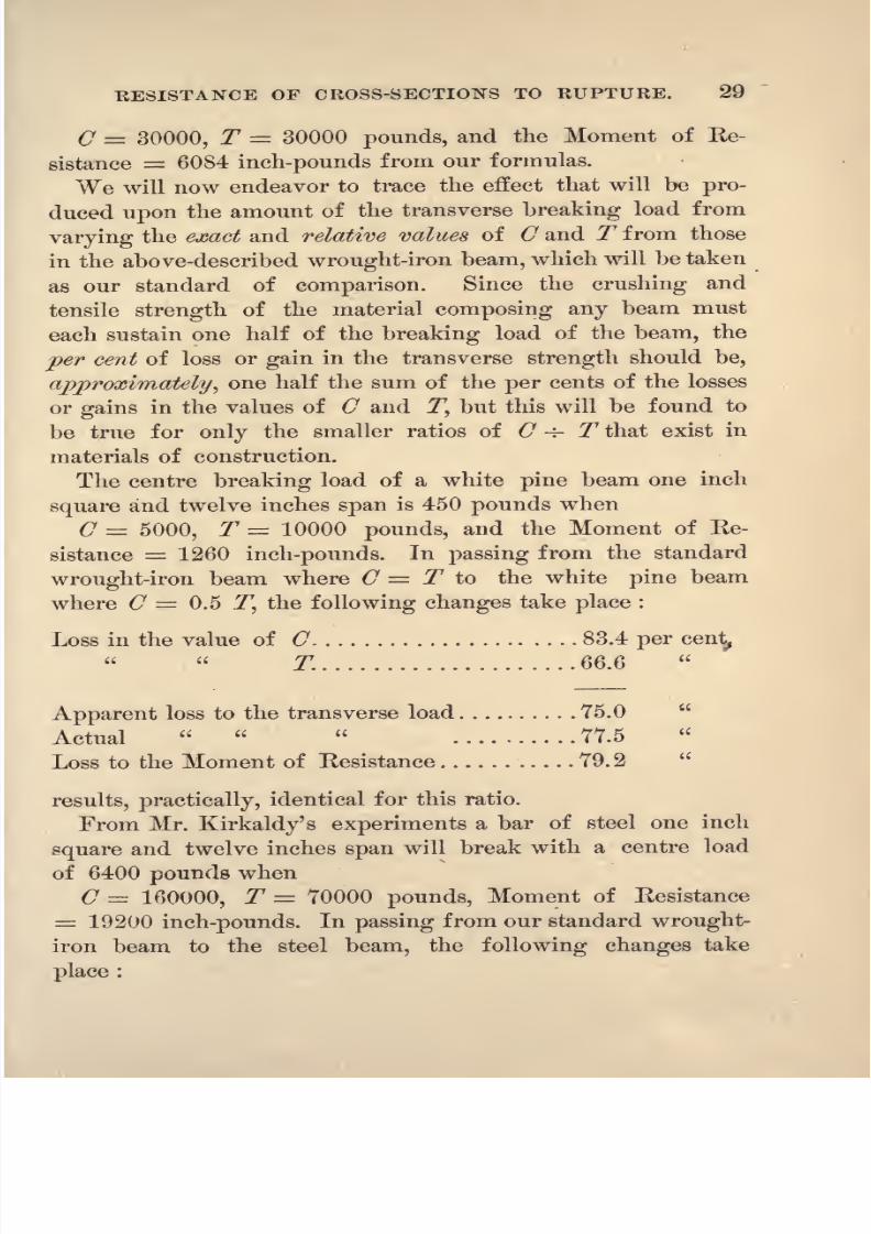
30 STRENGTH OF BEAMS AND COLUMNS.
Gain in the value of C 433.3 per cent.
T 133.3
Apparent gain to the transverse load 283.3
Actual 220.0
Gain to the Moment of Resistance 215.0
Mr. Hodgkinson found the centre breaking load of a certain
cast-iron beam, one inch square and twelve inches span, to be2000 pounds when
C = 115000, T = 14200 pounds, and the Moment of Re-
sistance = 6600 inch-pounds. In passing from our standard
wrought-iron to the cast-iron beam of the same size, the
following changes take place :
Gain in the value of C-|-
283.4per
cent.
Loss T . . . 52.6
Apparent gain to the transverse load .... 115.4
Actual
0.0
Gain to the Moment of Resistance 8.4
In this experiment it required 283.4 per cent gain in the
value of C to offset a loss of 52.6 per cent in the value of T,
or that the compressive strength does not sustain its proper
proportion of the load.
This great discrepancy between the legitimate theoretical
deductions and the results obtained from experiments cannot
be reconciled on the hypothesis that the forces are in equi-
librium with
respect
to an axis that lies writhin the beam,
the moment in each case, for rectangular sections, being the
resultants of the tensile and compressive forces, multiplied bytwo thirds of the depth of their respective areas, showing that
the compressive strain works under no disadvantages ;but on
our theory this discrepancy is fully accounted for. The lever-
arm of the crushing resultant is one third the depth of the

8/14/2019 A theoretical and practical treatise on the strength of beams and columns (1889)
http://slidepdf.com/reader/full/a-theoretical-and-practical-treatise-on-the-strength-of-beams-and-columns-1889 49/196
RESISTANCE OF CROSS-SECTIONS TO KUPTUKE 31
compressed area, while that of the tensile resultant is only
one thirdless
than thetotal
depth of rectangular beams.
27. Summary of the Theory. The theory herein
advanced to explain the relation that exists between the Bend-
ing Moment of the applied load and the Moment of Resist-
ance of the material composing the beam, may be expressed bythe following hypotheses :
1st. The fibres of the beam on its convex side are extendedand those on the concave side are compressed in the direction
of the length of the beam, and there are no strains but those
of extension and compression.
2d. There is a layer or plane of fibres between the extended1
and compressed sides of the beam that is neither extended nor
compressed, which is called the neutral surface or neutral line
for any line in this plane.
3d. The strains of compression and extension in the fibres of
the beam are, in intensity, directly proportional to their dis-
tance from the neutral surface.
4th. The axis or origin of moments for the tensile and com-
pressive resistance of the fibres of any section at right angles
to length of the beam, is a line of the section at its intersection
with the top or compressed side of the beam.5th. The fibres of a beam will be ruptured by either the
tensile or compressive strains in its concave and convex sur-
faces, whenever they reach in intensity those found by experi-
ment to be the direct breaking tensile and compressive fibre
strains for the material composing the beam.
6th. The Bending Moment of the load at any section is
equal to the sum of the moments of resistance to compression
and extension of the fibres, or to the Moment of Resistance of
the section of the beam.
7th. The sum of the moments of resistance of the fibres to
compression is equal to the sum of the moments of resistance
of the fibres to extension.

8/14/2019 A theoretical and practical treatise on the strength of beams and columns (1889)
http://slidepdf.com/reader/full/a-theoretical-and-practical-treatise-on-the-strength-of-beams-and-columns-1889 50/196
32 STRENGTH OP BEAMS AND COLUMNS.
8th. The algebraic sum of the direct forces of compression
and extension can never become zero.
9th. The Moment of Resistance of the section is equal to
the sum of the moments of resistance to the compression and
extension of its fibres.
10th. The transverse elastic limit load produces the tensile
and compressive fibre strain elastic limits.
8/14/2019 A theoretical and practical treatise on the strength of beams and columns (1889)
http://slidepdf.com/reader/full/a-theoretical-and-practical-treatise-on-the-strength-of-beams-and-columns-1889 51/196
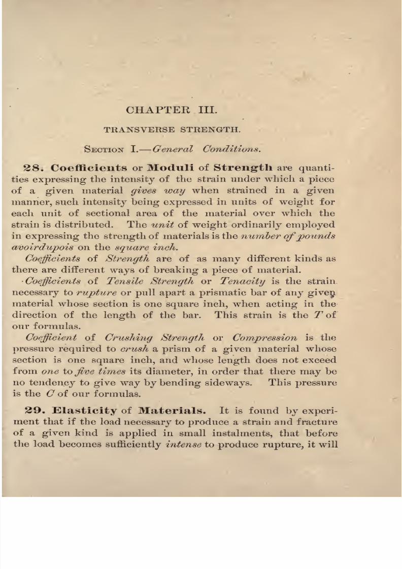
CHAPTER III.
TRANSVERSE STRENGTH.
SECTION I. General Conditions.
28. Coefficients or Moduli of Strength are quanti-
ties expressing the intensity of the strain under which a piece
of a given material gives way when strained in a given
manner, such intensity being expressed in units of weight for
each unit of sectional area of the material over which the
strain is distributed. The unit of weight ordinarily employed
in expressing the strength of materials is the number ofpounds
avoirdupois on the square inch.
Coefficients of Strength are of as many different kinds as
there are different ways of breaking a piece of material.
Coefficients of Tensile Strength or Tenacity is the strain
necessary to rupture or pull apart a prismatic bar of any given
material whose section is one square inch, when acting in the
direction of the length of the bar. This strain is the T of
our formulas.
Coefficient of Crushing Strength or Compression is the
pressure required to crush a prism of a given material whose
section is one square inch, and whose length does not exceed
from one iofive times its diameter, in order that there may be
no tendency to give way by bending sideways. This pressure
is the C of our formulas.
29. Elasticity of Materials. It is found by experi-
ment that if the load necessary to produce a strain and fracture
of a given kind is applied in small instalments, that before
the load becomessufficiently intense to produce rupture, it will

8/14/2019 A theoretical and practical treatise on the strength of beams and columns (1889)
http://slidepdf.com/reader/full/a-theoretical-and-practical-treatise-on-the-strength-of-beams-and-columns-1889 52/196
34 STRENGTH OF BEAMS AND COLUMNS.
cause a change to take place in the form of the material, and
if
the load is removed before this intensity of the fibre strain
passes certain limits, the material possesses the power of re-
turning to its original form. This is called its elasticity.
3D. Elastic Limits. When the material possesses the
power of recovering its exact original form without set on
the removal of a load of a given intensity, the greatest load
under which it will do this is called the limit of perfect elas-
ticity.
The limit of elasticity as ordinarily defined and used by
experimenters is that point or intensity of strain where equal
instalments or increments of the applied load cease to pro-
duce equal changes of form, or where the change in form in-
creases more rapidly than the load.
31. The Elastic Limit of Beams may be deter-mined by applying small equal parts of the load and noting
the increase in deflection after each increase of the load, al-
lowing sufficient time for each increase of the load to pro-
duce its full effect. When it is found that the deflections
increase more rapidly than the load, its elastic limit has been
reached and passed. The relation between the elastic limit
load of the beam and the elastic limit of the tensile and com-pressive fibre strains of the material composing the beam will
be shown in the sequel, or that the elastic limit load of the
beam produces the elastic limit strain for the fibres.
32. Working Load and Factor of Safety.The greatest load that any piece of material, used in a struc-
ture, is expected to bear is called the working load.
The 'breaking load to be provided for in designing a piece
of material to be used in a structure is made greater than the
working load in a certain ratio that is determined from ex-
perience, in order to provide for unforeseen defects in the
material and a possible increase in the magnitude of the ex-
pected working load.

8/14/2019 A theoretical and practical treatise on the strength of beams and columns (1889)
http://slidepdf.com/reader/full/a-theoretical-and-practical-treatise-on-the-strength-of-beams-and-columns-1889 53/196
TRANSVERSE STRENGTH. 85
The factor of safety is the ratio or quotient obtained by
dividing the breaking load by the working load required.
33. General Formula. In our first chapter we
deduced rules or formulas, from which can be computed the
Greatest Bending Moment that a load applied to a beam in a
given manner will produce without reference to the shape of
its cross-section, or to the material composing the beam.
In our second chapter principles are deduced from whichcan be computed the Greatest Moment of Resistance cross-
sections of the various shapes and material will exert at the
instant of rupture, without reference to the length of the beam
or to the manner in which the load may be applied.
To avoid repetition, the formulas for the Moments of Re-
sistance are deduced in this chapter. Our knowledge of the
transverse strength of beams will now be complete if we com-
pute and make the Greatest Moment of Resistance of the
cross-section of the beam equal to the Greatest Bending
Moment of the applied load.
Let 1? = the Greatest Moment of Resistance of the 'beam,
L = the total applied load in pounds, ,
s = the span, the distance between the supports in
inches,
n = the factor defined in Art. 6, page 7,
M = the Greatest Bending Moment' of the applied
load.
From Eq. 8, page 7, we have
M = nLs R,
. . L = -, (21)ns
from which the breaking load of the beam may be computed.
34. Relative Transverse Strength of a Beam.
Referring to the values of the factor, n, of Eq. 21, as given

8/14/2019 A theoretical and practical treatise on the strength of beams and columns (1889)
http://slidepdf.com/reader/full/a-theoretical-and-practical-treatise-on-the-strength-of-beams-and-columns-1889 54/196

8/14/2019 A theoretical and practical treatise on the strength of beams and columns (1889)
http://slidepdf.com/reader/full/a-theoretical-and-practical-treatise-on-the-strength-of-beams-and-columns-1889 55/196

8/14/2019 A theoretical and practical treatise on the strength of beams and columns (1889)
http://slidepdf.com/reader/full/a-theoretical-and-practical-treatise-on-the-strength-of-beams-and-columns-1889 56/196

8/14/2019 A theoretical and practical treatise on the strength of beams and columns (1889)
http://slidepdf.com/reader/full/a-theoretical-and-practical-treatise-on-the-strength-of-beams-and-columns-1889 57/196

8/14/2019 A theoretical and practical treatise on the strength of beams and columns (1889)
http://slidepdf.com/reader/full/a-theoretical-and-practical-treatise-on-the-strength-of-beams-and-columns-1889 58/196
40 STRENGTH OF BEAMS AND COLUMNS.
From Eq. 28, page 38, deduce the value of r/T,
7 _ m:
T~
and
which gives the required position of the neutral line, illus-
trated in Examples 1, 2, 21, 22 and 35.
The crushing strength can be computed by deducing its
value, 6 ,from Eq. 27,
..<7=J^L, (31)mbdc
The application is illustrated in Examples 1, 2 and 21.
PROBLEM II. The position of the neutral line and the
tensile strength of the material of a rectangular section maybe computedfrom the known transverse breaking load of the
beam and the crushing strength of the material.
From Eq. 27 we have
(32)
for the position of the neutral line, whichis
illustrated in Ex-ample 4.
From Eq. 28 we have for the required tensile strength
= ~' (33)
illustrated in Example 4.

8/14/2019 A theoretical and practical treatise on the strength of beams and columns (1889)
http://slidepdf.com/reader/full/a-theoretical-and-practical-treatise-on-the-strength-of-beams-and-columns-1889 59/196
TRANSVERSE STRENGTH. 41
SECTION III. Transverse Strength Hodgkinson Section.
4O. Moment of Resistance. In Fig. 15 let ABDXrepresent the section, AOX the axis or origin of moments,
nl the neutral line, the area above it being compressed andthat below it extended.
OnEMnNO, a section through the strain wedges on the
line OE.
d = the depth of the web and section, OE, in inches,
dl= the
upper flanges in inches,
dt= the
lower
1) the width of the web in inches,
Jj the sum of the widths of the upper flanges in inches,
or AX&,
&2
the sum of the widths of the lower flanges in inches,
or BD - I.
For other notation refer to Art. 35.
From Eqs.11
and 12, page 10,we have for the moments of
eompressive resistance,
ld*CWeb, 7?c
=-,
Upper flanges,7?
c= -
(3d-
2d>) C.

8/14/2019 A theoretical and practical treatise on the strength of beams and columns (1889)
http://slidepdf.com/reader/full/a-theoretical-and-practical-treatise-on-the-strength-of-beams-and-columns-1889 60/196
42 STRENGTH OF BEAMS AND COLUMNS.
Adding, we obtain for the section,
and for the moments of tensile resistance from Eqs. 13 and
14, page 11,
Lower flanges, ^T = gy [zdtdT (2^ - dt) d? (3d - M,)~\ T.
Adding the above equations we obtain for the moment of
tensile resistance of the section,
R,= WTW+rfc) + ,,[3dA(2d-d,)-d,'(3d-2d,)] (35)
and the Moment of Resistance of the Hodgkinson section is
= 2/4 from Eqs. 34 and 35.
41. The Neutral Line. By equating the values of
ftc and 7?T given by Eqs. 34 and 35, and deducing from the
equation so formed the value of d^ the position of the neutral
line is determined, but as this will involve the solution of a
biquadratic equation, the general solution will be too complex
for ordinary use.
The following approximate formula obtained by neglecting
certain quantities that do not materially affect the result in
ordinary cases, will give its position sufficiently near for all
practical purposes when the beam is made of cast-iron :
d = d + ^m<MA (q
(q -f 1)
Its application is illustrated in Examples 8, 9, 10 and 29.
The position of the neutral line in .a Hodgkinson or in
any single or double flanged beam may be computed when
the transverse strength of the flanged beam and either the
8/14/2019 A theoretical and practical treatise on the strength of beams and columns (1889)
http://slidepdf.com/reader/full/a-theoretical-and-practical-treatise-on-the-strength-of-beams-and-columns-1889 61/196

8/14/2019 A theoretical and practical treatise on the strength of beams and columns (1889)
http://slidepdf.com/reader/full/a-theoretical-and-practical-treatise-on-the-strength-of-beams-and-columns-1889 62/196
44 STRENGTH OF BEAMS AND COLUMNS.
the applied load and the Moment of Resistance of the section,
all of the terms become known quantities except dT ; substitut-
ing for the letters their values in any given case, it will
always reduce to the following general form :
dj adT
* mdT n 0,
in which $, w, and n are numerical quantities. By substitut-
ing for dT a new unknown quantity,
the equation will reduce to the following general form :
x3
Zpx 2& 0, (B 36)
which can be solved by Cardan's Rule, as in the preceding
Problem.
42. Transverse Strength. To obtain a general
formula from which the transverse strength of a Hodgkinson
beam may be computed, place for 7?, the Moment of Resist-
ance in Eq. 22, page 36, its values, 2#c= 2^x,
from Eqs. 34
and 35, and we have
L = H1 + M,
1
(3rfc - 3d,), (37)
and
From either of these formulas, either the breaking or elastic
limit load
maybe
computed.Their
applicationis illustrated
in Examples 8, 9, 10, 22, 29, 30 and 31.
43. To Design a Hodgkinson Beam. An econom-
ical position for the neutral line must be assumed and a suffi-
cient area of the metal arranged above and belowit,
to furnish
the required compressive and tensile resistance ; the depth of

8/14/2019 A theoretical and practical treatise on the strength of beams and columns (1889)
http://slidepdf.com/reader/full/a-theoretical-and-practical-treatise-on-the-strength-of-beams-and-columns-1889 63/196

8/14/2019 A theoretical and practical treatise on the strength of beams and columns (1889)
http://slidepdf.com/reader/full/a-theoretical-and-practical-treatise-on-the-strength-of-beams-and-columns-1889 64/196
46 STRENGTH OF BEAMS AND COLUMNS.
One half of this computed width, J,,must be arranged on
each side of the web.
FOR THE EXTENDED AREA :
Step IV, Substitute for R, in Eq. 22, page 36, its value
from Eq. 13, page 11, and we will have for the load, Z3 ,sus-
tained by the extended area of the web, *
(43)
Step V, For the bottom flanges deduct the load, Zs,
found by Step IY., from one half of the required breaking
load, Z, of the beam;the remainder will be the load, Z4 ,
that
must be sustained by the bottom flanges,or
Lt = ^-Ly
'
(44)
In order to design an area for the bottom flanges that will
sustain this load Z4 ,we must assume a convenient depth, d
for the bottom flanges, and obtain the sum of their widths, J2 ,
by substituting for R, in Eq. 22, its value for this case from
Eq. 14, page 12, and we will have
?,/* (2d-
4)-
d; (3d-
2^) , (45)
from which we deduce
____d,)-
d? (3d - 2<72)]mT
One half the width computed from this formula must be
arranged on each side of the web.
Step VI. Should the computed dimensions from those
assumed produce a badly designed section, new dimensions
must be assumed from the knowledge thus obtained, and a
second computation made as in the first instance.

8/14/2019 A theoretical and practical treatise on the strength of beams and columns (1889)
http://slidepdf.com/reader/full/a-theoretical-and-practical-treatise-on-the-strength-of-beams-and-columns-1889 65/196
TRANSVERSE STRENGTH. 47
SECTION IY. Transverse Strength Double T and Hollow
Rectangle or Box Section.
44. Moment of Resistance. Let Fig. 16 represent
the sections of the Double T and Box Sections respectively ;the
same letters in the text apply to both sections.
A
Let ABDX represent the sections, OnEMnNO a section
through the strain wedge on the line OE, AOX the axes, and
nl the neutral lines.
Notation for the Double T :
~b = the width of the web in inches,
Jj = Z>2= the sum of the widths of the flanges of the double
T in inches, or AX2>,
dl= the depth of the top flanges of the double T,
d,= the
bottom
t
Notation for the Box Section :
1) the sum of the widths of the sides of the box in
inches,
Jj= J
2= the inside width of the box,
^ = the depth of the top of the box,
d,= the
bottonl of the box.
Giving the letters the above definition the moments of tensile

8/14/2019 A theoretical and practical treatise on the strength of beams and columns (1889)
http://slidepdf.com/reader/full/a-theoretical-and-practical-treatise-on-the-strength-of-beams-and-columns-1889 66/196

8/14/2019 A theoretical and practical treatise on the strength of beams and columns (1889)
http://slidepdf.com/reader/full/a-theoretical-and-practical-treatise-on-the-strength-of-beams-and-columns-1889 67/196
TRANSVERSE STRENGTH. 49
Bending Moment of the applied load from Eq. 11, page 10,
beingsubstituted for
Rin
Eq. 22, page 36,will
givefor its
proportion of the load
_ mbd^CA -
~67 '
Step III. For the top flanges of the Double T or the
top of the Box Section deduct the load, Z15found by Step II.
from one half of the total applied load, L;the remainder
will be the breaking load, Z2 ,for the top flanges or the top
of the box, as the case may require, or
A =\- Lv (53)
To design an area of section that will resist this load, .Z2 ,
assume a width, b19 for the sum of the widths of the top flanges
or the top of the Box, and compute therefrom their depth, dl9
by substituting for the moment of compressive resistance, R,
in Eq. 22, page 36, its value in this case from Eq. 12, page 10,
and we will have
~
(54)
from which deducing the value of d1 by making d? = d*,
which may be done without appreciably affecting the result
obtained, we have
dj
e
(
from which the required depth may be computed.
FOE THE EXTENDED AREA I
Step IV. The moment of the tensile resistance that the
web of the Double T or the sides of the Box Section will
offer to the breaking moment of the applied load, Z, will be

8/14/2019 A theoretical and practical treatise on the strength of beams and columns (1889)
http://slidepdf.com/reader/full/a-theoretical-and-practical-treatise-on-the-strength-of-beams-and-columns-1889 68/196
50 STRENGTH OF BEAMS AND COLUMNS.
obtained from Eq. 13, page 11, which being placed for R in
Eq. 22, page 36, gives for its proportion of the load, Z 3 ,
vn TL,= MT (2d+ dc)~. (56)
Step V. The bottom flanges of the Double T or the
bottom of the Box Section must sustain as its proportion of the
load, Z4,
L*=\- A- (67)
In order to design an area that will sustain this load, Z4 ,
assume a width, #a=
5,, the width assumed in Step III., and
compute the corresponding depth, d by placing for 7?, in
Eq. 22, the value of the moment of the tensile resistance for
this case, from Eq. 14, page 12, and we have
-d.)-
d: (3d-
24) (68)
from which, deducing the value of da by making d*
we have
,
_ rm-I
mT
-ts
m (3c?T
-f3d
+ 2)* /KQN26 2mr(3e^+ 3d+ 2)
from which the required depth may be computed.
Step VI. Should the section obtained by this process
not be satisfactory new dimensions must be assumed to remedy
the defects of form, and the process repeated.
CAST- RON DOUBLE T AND Box SECTIONS:
For the Box or Hollow rectangular beam the assumed
widths, Jj= J
9 ,must be placed between the sides of the box,
that having the depth, d^ from Eq. 55, must be placed at the
top, and da , computed from Eq. 59, at the bottom of the Box
beam.

8/14/2019 A theoretical and practical treatise on the strength of beams and columns (1889)
http://slidepdf.com/reader/full/a-theoretical-and-practical-treatise-on-the-strength-of-beams-and-columns-1889 69/196
TRANSVERSE STRENGTH. 51
For the Double T beam the assumed width, bl= &
2 ,must
be placed in equal projecting flanges on each side of the webat the top and bottom, that having the depth d
1at the top
and dzat the bottom of the beam.
WROLTGHT- RON DOUBLE T AND Box SECTION.
For the Box or Hollow rectangular beam made of riveted
plates a part of the assumed width, 11
= >
2 ,must be placed be-
tween the sidesof the Box and the balance
in
two equal project-
ing flanges 011 the outside of the Box at the top and bottom;the
total width of the rolled plate that forms the top and bottom
of the Box is equal to (b -j- 5,),and the depth of the plates
that form its sides is equal to d (dl -\- d^) as found by Steps
III. and Y.
For the Double T :
Riveted plate sections. The width of the top and bottom
plates is equal to (b+ &a),
and the depth of the web plate is
d-ti+ d,).
tolled Eyebeams are arranged like that for a cast-iron
Double T beam.

8/14/2019 A theoretical and practical treatise on the strength of beams and columns (1889)
http://slidepdf.com/reader/full/a-theoretical-and-practical-treatise-on-the-strength-of-beams-and-columns-1889 70/196
STRENGTH OF BEAMS AND COLUMNS.
SECTION Y. Transverse Strength.
The Inverted T, Double Inverted T and [_J Sections.
48. Moment of Resistance. Let Figs. 17, 18 and
19 respectively represent the three sections, nl the neutral
lines, and .4^ the axes or origin of moments of resistance for
each section;,
Fxp 17
A
-.1
f
VIn addition to the notation given in Art. 35, observe the
following for use in the formulas given in this Section :
The Inverted T, Fig. 17.
b = the width of the web in inches,
Ja= the sum of the widths of the
flanges, or BD b,
d^= the
depth
of the
flanges
in inches.
The Double Inverted T, Fig. 18.
J the sum of the widths of the webs in inches,
2=
flanges, or MN -h,
d^=. the depth of the flanges in inches.
The y Section, Fig. 19.
1 = the sum of the widths of the webs in inches,
>
2 = the width of the bottom in inches, or OP Z>,
d2= the depth of the bottom in inches.
Noting the above definitions, the moment of compressive
resistance for each section will be from Eq. 11, 'page 10,
(60)

8/14/2019 A theoretical and practical treatise on the strength of beams and columns (1889)
http://slidepdf.com/reader/full/a-theoretical-and-practical-treatise-on-the-strength-of-beams-and-columns-1889 71/196
TRANSVERSE STRENGTH. 53
and for the moment of tensile resistance the formula given
for the Hodgkinsoii beam will apply, or
J??T from Eq. 35, page 42.
The Moment of Resistance of the section will b
=fic+ 2tv = 27?
c
from the above equations.
49. The Neutral Line. In cast-iron beams of tin
sections the neutral line will be given approximately by the
following formula :
, _ di + vmdf>,d, (3+ 1)+ VcH&i+l)
5O. Transverse Strength. Place for It in Eq. 22
the values for the Moment of Resistance of the sections, andwe will have
L =, (64)
08
and
L from Eq. 38, page 44. (65)
From either of these formulas the transverse breaking load
may be computed.
51. To Design an Inverted T, Double In-
verted T and |_| Sections.
Step I. Assume a value for the depth, d, and the width
or sum of the widths of the webs, 5, and an economical posi-
tion for the neutral line, and from these compute the other
dimensions.
Step II. The compressed area above the neutral line
must have a moment of resistance equal to one half the Bend-
ing Moment of the applied load, Z, or
M C Zs(
6 2m

8/14/2019 A theoretical and practical treatise on the strength of beams and columns (1889)
http://slidepdf.com/reader/full/a-theoretical-and-practical-treatise-on-the-strength-of-beams-and-columns-1889 72/196
54 STRENGTH OF BEAMS AND COLUMNS.
If our assumed values for b and dcdo not satisfy this equa-
tion, other values must be assumed until the two members
give identical numerical quantities.
FOR THE EXTENDED AREA I
Step III. The load, Z, sustained by the extended area of
the web or webs, #, may be obtained by substituting their mo-
ments si resistance for R in Eq. '22, page 36, its value from
Eq. 13, page 11,
(67)
Step IV, For the flanges and bottom deduct the load Z:
found by Step III., from one half of the applied load Z, the
remainder, Za,is the load that must be sustained by the flanges
and bottom.
Z. = |-Z... . (68)
In order to design an area that will sustain this portion Z2
of the applied Z, assume a convenient depth, d^ and from this
compute the width 62 , by substituting for 7? in Eq. 22, page
36,its
value,the
moment of tensile resistance for this casefrom Eq. 14, page 12,
Z2= 3d,dr (2d
-d>)-
d: (3d-
2^)1 , (69)
from which
___ ___dA (2d - rfj - d,
2
(3d - 2d2 ) mT'
which gives the required width.

8/14/2019 A theoretical and practical treatise on the strength of beams and columns (1889)
http://slidepdf.com/reader/full/a-theoretical-and-practical-treatise-on-the-strength-of-beams-and-columns-1889 73/196
TRANSVERSE STRENGTH.
SECTION YI. Transverse Strength Circular Sections.
52. Moment of Resistance. In Eig. 20, let BnOl
representthe section, BnOMnNB a section through the
strain wedges on the line BO, B the origin of co-ordinates,
DBS the axis or origin of moments, nl the neutral line, nBl
the compressed area, and nOlthe extended area
Adopting the notation heretofore used and defined, we
have
C= the greatest intensity of the compressive strain in pounds,
pe r square inch,
T= the greatest intensity of the tensile strain in pounds,
per square inch,
J?T = the moment of the tensile resistance in inch-pounds,
7?c= the moment of the compressive resistance in inch-
pounds,
R= the Moment of Resistance of the
section,d
c= the versine Bn of one half of the arc nBl in inches,
</T= the versine On of one half of the arc nOl in
inches,
d =. dc -f- dT the diameter of the circle in inches,
r = the radius of the circle in inches,
q the quotient arising from dividing C by .T7
,

8/14/2019 A theoretical and practical treatise on the strength of beams and columns (1889)
http://slidepdf.com/reader/full/a-theoretical-and-practical-treatise-on-the-strength-of-beams-and-columns-1889 74/196
56 STRENGTH OF BEAMS AND COLUMNS.
Lthe total
appliedload in
pounds,s = the span, the distance between the supports
in inches,
m = the factor denned in Art. 34, page 35,
Comp. arc = the arc bounding the compressed area in
inches,
Tension arc the arc bounding the extended area in inches.
For the moment of compressive resistance from Eq. 15,
page 14, we have
c
+ Comp. arc (12dc-
15r)/],(71)
and for the moment of tensile resistance
*
(6r-
4) + 18r' (r-
dfi
+ Tension arc (12^T 9r) r9
J,(72)
and for the Moment of Kesistance of the circular section,
27?T . (73)
53. The Neutral Line, The position of the neutral
line in circular wooden, cast-iron, wrought-iron, and steel beams
will be found tabulated on pages 80, 100 and 112.
54, TransverseStrength, Substituting
for R, in
Eq. .22, page 36, its value 2#c = 27?T from Eqs. 71 and 72,
we have
+ Comp. arc (12<7C-
15r)r5
, (74)

8/14/2019 A theoretical and practical treatise on the strength of beams and columns (1889)
http://slidepdf.com/reader/full/a-theoretical-and-practical-treatise-on-the-strength-of-beams-and-columns-1889 75/196
TRANSVERSE STRENGTH. 57
and
mT , . r^r- r .
^ (5/. _ ^+ lSr
,
(r_
+ Tension arc (l2dT-
9r) r* , (75)
from which the breaking load of a circular beam may be com-
puted. By observing the following equalities,much time and
labor will be economized in
comparingthe results
computedfrom these formulas :
(dc-
r) + r*(30/-
- 14dc)]
ISr* (r-
=
Comp. arc = %7rr Tension arc.
Another Method, The Moments of Resistance of
circular sections are to each other as the cubes of their radii /
hence by computing and tabulating the Moments of Resist-
ance for all required positions of the neutral line, in a circle
whose radius is unity, those for any other circle composed of
the same material may be computed by multiplying the
tabular number by the cube of the radius.
Let yc= the second member of Eq. 74, when r = 1, except
,, ., mCthe iactor ---
,
,, ,
mTthe factor -- .
s
/T the second member of Eq. 75, when r = 1, except
(76)
and
L = ?&. (77)

8/14/2019 A theoretical and practical treatise on the strength of beams and columns (1889)
http://slidepdf.com/reader/full/a-theoretical-and-practical-treatise-on-the-strength-of-beams-and-columns-1889 76/196
58 STRENGTH OF BEAMS AND COLUMNS.
The application of Eq. 76 is illustrated in Examples 11, 32
and 33, and Eq. 77 in Examples 12, 13 and 14.
Tables giving the computed values of fcand f^ for the
different positions of the neutral line in cast-iron, wrought-
iron and steel, circular sections, whose radius is unity, are
given on pages 80 and 100.
55. To Compute the Compress ve Strain.
PROBLEM. The position of the neutral line and the com-
pressive strain of the material of a circular section may he
computedfrom the known transverse breaking load and tensile
strength of the material.
Deducing the value of fT from Eq. 77, we have
from the proper table in the sequel take the value of q cor-
responding to this value of fT ;then
C=qT. (79)
Illustrated by Examples 3 and 23.
56, To Compute the Tensile Strain.PROBLEM. The tensile strain of the material of a circular
section may be computed from the known transverse break-
ing load and compressive strength of the material.
From Eq. 76 deduce the value of f^
(80)
From the Table given in the sequel for the material take the
value of, corresponding to the computed value of/c ,
then
T=~. (81)2
Illustrated by Example 24.

8/14/2019 A theoretical and practical treatise on the strength of beams and columns (1889)
http://slidepdf.com/reader/full/a-theoretical-and-practical-treatise-on-the-strength-of-beams-and-columns-1889 77/196
TRANSVERSE STRENGTH. 59
57. Relative Strength of Circular and Square
Beams. Constant ratios exist between the Moments of Re-
sistance of the circle and its inscribed, circumscribed and equal
area square, when the material composing the square and
the circle has the same tensile and compressive strength, and
consequently the same ratios exist between the transverse
strength of the beams of which they are sections, the span and
manner of loading the circular and square beam being the
same.
General Formula :
Let f the position of the neutral line in the square when
the side is unity, and d* f*d?, b = d and r3 =
,
8
hence,
Strength- of the Square =^d
' C
=^ ^ from Eq. 23.
Strength of the Circle = r*feC=c
,from Eq. 76,
8
from which we have
Square : Circle : :
3 8
. . Circle = Square X |.
(82)*
CASE I. When the circle is inscribed within the square,
d = d, and Eq. 82 becomes
Circle = Square X ^4 (83)
J
Illustrated by Examples 15 and 16 of the sequel.
CASE II. When the square is inscribed within the circle side
of the square, d = diameter of the circle d X 0.707, and Eq.
82 becomes
Circle = Square X - (84)
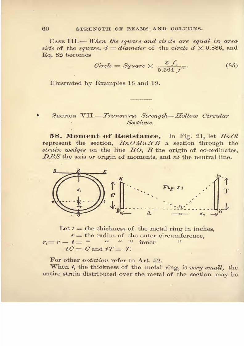
8/14/2019 A theoretical and practical treatise on the strength of beams and columns (1889)
http://slidepdf.com/reader/full/a-theoretical-and-practical-treatise-on-the-strength-of-beams-and-columns-1889 78/196

8/14/2019 A theoretical and practical treatise on the strength of beams and columns (1889)
http://slidepdf.com/reader/full/a-theoretical-and-practical-treatise-on-the-strength-of-beams-and-columns-1889 79/196
TRANSVERSE STRENGTH. 61
treated as if it was all concentrated in the outer surface of the
cylindrical beam ;if t is not very thin, r
^or the mean ra-
dius must he used instead of r in the following formulas.
Making the substitution of tC for C and tT for T in Eqs.
18 and 19, the moments of compressive and tensile resistance
become
^c=
<T7 Vd*d* X 2 (3r - dc)
+ Comp. arc (2dc
-3r) , (86)4ac
L. J
and
^T~
icTL ^^ X 2(/> + dT) + Tension arc (2cZT r)T(87)
For the Moment of Resistance of the section,
R = Rc 4- J?T = 27?c = 2^T . (88)
59, The Neutral Line, The position of the neutral
line in hollow circular sections of cast-iron, wrought-iron and
steel, when the radius of the outer circumference is unity, will
be found tabulated in the sequel.
60, Transverse Strength. Substituting for the
Moment of Resistance R, in Eq. 22, page 36, its values in this
case, 2/?c= 27?T ,
from Eqs. 86 and 87, we have
mrtCr ~|Z =s [
VdcdT X 2 (3r dc) -\-Comp. arc (2dc 3r)J?(o9)
and
JL ^=~~\^ X 2
(/>+ ^T) + Tension arc (2dT-
r)J.(90)
From either of the above formulas the transverse strength of
hollow cylindrical beams may be computed.

8/14/2019 A theoretical and practical treatise on the strength of beams and columns (1889)
http://slidepdf.com/reader/full/a-theoretical-and-practical-treatise-on-the-strength-of-beams-and-columns-1889 80/196
62 STRENGTH OF BEAMS AND COLUMNS.
In these formulas the following equalities exist :
2 (3r- dc)= Vd^dT X 2
(/ + d,
Comp. arc = 'Znr Tension arc.
When the metal ring is very thin, r in the above formulas
is the radius of .the outer circle, otherwise it is the radius of
the mean circle, r .
Another Method, The Moments of Resistance of thin
hollow circular sections are to each other as the squares of
their radii; hence, by computing and tabulating the Moments
of Resistance for all required positions of the neutral line, in a
thin hollow circle whose radius is unity, those for any other
thin hollow circle composed of the same material may be
computed by multiplying the tabular number by the square of
the radius.
e the second member of Eq. 89, when radius 1, ex-
u x-i mtCcept the factor --,
fT the second member of Eq. 90, when radius = 1, ex-
. ,, , mtTcept the tactor- .
s
With this notationEqs.
89 and 90 become
and
L =?. (92)

8/14/2019 A theoretical and practical treatise on the strength of beams and columns (1889)
http://slidepdf.com/reader/full/a-theoretical-and-practical-treatise-on-the-strength-of-beams-and-columns-1889 81/196
TRANSVERSE STRENGTH. 63
Tables giving the computed values offc andfT for thp posi-
tions of the neutral line in thin hollow circles, whose radius is
unity, will be found in the sequel.
The application of the above formulas is illustrated in
Examples 20 and 34

8/14/2019 A theoretical and practical treatise on the strength of beams and columns (1889)
http://slidepdf.com/reader/full/a-theoretical-and-practical-treatise-on-the-strength-of-beams-and-columns-1889 82/196

8/14/2019 A theoretical and practical treatise on the strength of beams and columns (1889)
http://slidepdf.com/reader/full/a-theoretical-and-practical-treatise-on-the-strength-of-beams-and-columns-1889 83/196
GENERAL CONDITIONS. 6fr
Elastic Limit. The extensions within the elastic limit fol-
low laws similar to those that govern the compressions. The^
elastic limit is about one half of the tensile strength.
63, Ratio of the Compressive to the Tensile
Strength. Experiments have demonstrated that the ratio
existing between the crushing and tensile strength of cast-iron
has a wider range of values than that for any other known
material, and that this results from great fluctuations in the
crushing rather than in the tensile strength. The extreme
values for the C -f- T = q of our formulas may be taken at
from 3 to 8J ;the tendency of improved methods of manu-
facture is to decrease, numerically, this ratio by increasing
that of T and decreasing that of C\ which in pure orwrought-
iron becomes C -=- T = 1.
64. Transverse Strength. Cast-iron breaking with
a well-defined fracture, its transverse strength may be com-
puted from our formulas when the crushing and tensile
strength of the identical cast-iron composing the beam is
known from experiment, as the values of C and T are found
to
vary
in an uncertain manner, withremelting, length
of
time in fusion, etc.
The transverse strength of some cast-iron does not increase
directly with the increase in the dimensions of its cross-section,
as it should in accordance with well-defined laws, but in a
lower ratio. This defect is usually imputed to unequal strains
being brought upon the metal in different parts of the section,
fromunequal temperatures
incooling,
but fewexperiments
have been made to test the matter.
Col. James, of England, planed out and tested a f-inch
square bar from a 2-inch square cast bar, the values of C and
Tior this brand of iron, Clyde No. 3, having been determined
from experiments by Mr. Eaton Hodgkinson. The following
is the result of Col. James's tests :

8/14/2019 A theoretical and practical treatise on the strength of beams and columns (1889)
http://slidepdf.com/reader/full/a-theoretical-and-practical-treatise-on-the-strength-of-beams-and-columns-1889 84/196
66 STRENGTH OF BEAMS AND COLUMNS
Clyde No. 3. The Dressed Bar. Transverse Load.
O= 106039 Ibs. C = 60233 Ibs. by test. 193 Ibs. rough bar.
T= 23468 T 14509
by computation.* 134
planed out.
From the above it appears that the value of C decreased in
the planed-out bar 56.8 per cent
;that of T 60.5 per cent,
and the transverse breaking load 69.4 per cent. But this
result is contrary to that obtained in the following tests made
for the United States Government Reportof Tests of Iron arid
Steel for 1885.f In the United States Government tests the
bars were cast two feet in length and three inches in width,
with depths ranging from a half to two inches. The equiva-
lent centre breaking load for a bar of the metal one inch
square and twelve inches span was computed from the result
of each experiment, that they might be compared.
Condition. Rough. Edges Planed. Edges Planed. Planed all over.
No. Expts. 4 3 6 6
Size, 3 X 0 .5 2 X 1 to 1 .28 2 X 1 .5 to 2 2 X 1 .S5 to 1 .75
Load, Ibs., 2453 2136 2025 2134
The edges planed bars were reduced in width from the
rough castings that were 3 wide, the tension and compression
surfaces
being
left as they were cast.
The planed-all-over bars were cut from cast bars that
were three inches wide and two inches deep, equal depths of
metal having been removed from each face of the rough bar.
In these experiments the strength of the bars that were cast
two inches deep varied about five per cent from those cast
one inch deep, and the planed-out bars were as strong as
the
rough
cast bars of the same size.
The bars that were tested with the tension and compres-
sion surfaces as cast varied in strength about 5 per cent from
the average strength given above, and the planed-out
bars
*Example No. 4.
f Senate Ex. Doc. No. 36 49th Congress, 1st Session, p. 1162.

8/14/2019 A theoretical and practical treatise on the strength of beams and columns (1889)
http://slidepdf.com/reader/full/a-theoretical-and-practical-treatise-on-the-strength-of-beams-and-columns-1889 85/196
GENERAL CONDITIONS. 67
only 2J- per cent in strength from the averages given, indicat-
ing great uniformity in strength, and consequently no de-
crease in the values of C and T for the metal in the interior
of the cast bar, but this was not determined by direct exper-
iment.
The following ratios are usually quoted to illustrate the de-
preciation of the transverse strength of cast-iron beams re-
sulting from an increase in the size of the cross-section, the
strength that the large beam should have being computed
from that of the V X 1 bars, the latter being denoted by
100.
Experimenter. 1 X 1 2 X 2 3 X 3
Capt. James 100 71.84 61.95 per cent,
Mr. Hodgkinson.. 100 - 71.22
The transverse elastic limit load may be computed whenthe corresponding values of C and T have been determined
by experiment.
65. To Compute the Compressive and Tensile
Strength. The relation existing between the Transverse
Load, Compressive and Tensile Strength is such that the
value of any one of the three may be computed when the
value of the other two has been determined by direct experi-
ment;this relation is true for both the elastic limit and the
breaking values.
The beam from which the experimental breaking load was
obtained must have been sufficiently long to deflect a distance
equal to or greater than the depth of tension area that is re-
quired for true cross-breaking, or else our computed value of
C or T will be incorrect for the reason given in Art. 24.
Compressive Strength. This may be computed from the
known tensilestrengtii of the material and the transverse
breaking load of rectangular and circular beams, or of that
of any of the flanged beams when the neutral line lies within
the lower or tension flange.

8/14/2019 A theoretical and practical treatise on the strength of beams and columns (1889)
http://slidepdf.com/reader/full/a-theoretical-and-practical-treatise-on-the-strength-of-beams-and-columns-1889 86/196
68 STRENGTH OF BEAMS AND COLUMNS.
The cast-iron that Mr. Barlow used in his experiments was
composed of pig and scrap-iron ; he determined its tensile and
transverse strength, but he does not record in his Strength
of Materials
its crushing strength ;this we can compute from
the data given.
EXAMPLE 1. Required the Crushing Strength of Mr. Bar-
low's iron from the centre-breaking transverse load of a rect-
angular
beam when
The depth . .d = 1 inch, T 18750 pounds by experiment,
breadth I = 1.02 inch, L = 534 *
span . . . s =60. inches, m 4.
The position of the neutral line must be computed from
Eq. 30, page 40,
,
_ 3 X 1 /9 X 4 X 1.02(1)* i750 - 12 X 584 X 60 n ,,
2
V'
4 X 4 X 1.02 X 18750-
hence dc= 1 - 0.5032 = 0 .4968,
from which we can compute the value of the crushing strain
by means of Eq. 31,
The following Example is taken from Major Wade's Ex-
periments on the Strength and other Properties of Metals
for Cannon, made for the United States Government :
EXAMPLE 2. Required the Crushing Strength of MajorWade's cast-iron in third fusion, from the transverse strength
of a rectangular beam, when
The depth. ..d = 2.01 inches, T = 26569 pounds by test,
breadth I 2.008
L = 16172
span. . .. = 20. m = 4 for a centre load.
* Barlow's Strength of Materials, p. 152.
8/14/2019 A theoretical and practical treatise on the strength of beams and columns (1889)
http://slidepdf.com/reader/full/a-theoretical-and-practical-treatise-on-the-strength-of-beams-and-columns-1889 87/196
GENERAL CONDITIONS. 69
For the position of the neutral line, we have from Eq. 30,
3X2.01 _ /9~X 4x 2.008(2.01)^^6^ l2~Xl6172 X 20 _ft
,,
V'
4 X 4 X 2.008 X 26569
. . dc= 2.01 0.8835 = 1.1265 inches.
Then we can compute the crushing strength, (7,from Eq.
31,
n 3 X 16172 X 20~-
4 X 2.008 (1.1265?
= 952P
Unds '
EXAMPLE 3. Kequired the Crushing Strength of certain
cast-iron from the transverse strength of a circular beam
when
The diameter d 1//
.129, T 29400 pounds mean of tests,'
span ..... * = 20 .0, L = 2118 by test,
m = 4.
From Eq. 78 we have
- 2H8 X 20
4 (0.5645)3
29400~
From the Table, page 80, for the above value of fT,we have
q = 3.275, and from Eq. 79,
. . O= 29400 X 3.275 = 96285 pounds.
From the United States Government Report of the Tests of
Iron and Steel for 1884,* the mean crushing strength of
this cast-iron was C 100700 pounds.
The Crushing Strength may be computed from the Trans-
verse Strength of the Hodgkinson or any other flanged beam.
When the neutral line is not situated above the top line of the
tension flange, its position may be computed from Eq. 30,
page 40, as if the beam were rectangular. When the neutral
* Senate Ex. Doc. No. 35 49th Congress, 1st Session, p. 284.
8/14/2019 A theoretical and practical treatise on the strength of beams and columns (1889)
http://slidepdf.com/reader/full/a-theoretical-and-practical-treatise-on-the-strength-of-beams-and-columns-1889 88/196
70 STRENGTH OF BEAMS AND COLUMNS.
line is located above the top line of the tension flange,its
position can be determined by the method given in Problem I.,
page 43, but in either case the value of C must be computed
by formula 37, page 44, C being then the only unknown
quantity that it will contain.
Tensile Strength. This may be computed from the known
Crushing Strength of the material and the Transverse
Strengthof
any rectangular,circular or
flangedbeam.
EXAMPLE 4. Required the Tensile Strength from the Trans-
verse Strength of a rectangular beam made of a certain kind
of cast-iron that was tested by Captain James, of England,*
when
The depth d = 0.75 inches, O= 60233 pounds by test,
breadth b = 0.75
L = 134
span s = 54.0 m = 4
The position of the neutral line is to be computed from Eq.
32, page 40,
, /
'== *
3 X 134X54
4X07X0288'
hence dT = 0.75 0.4 0.35 inches.
Then we compute the required value of the tensile strength,
T, from Eq. 33, page 40,
3 X 134 X 54T : =
4x0.75x0.85(2x0.75+0.4)== 14509
Mr. llodgkinsoii determined for this iron,
Clyde, No. 3, C = 106039 and T = 23468 pounds.
* British Report on the Application of Iron to Railway Structures,
p. 257.

8/14/2019 A theoretical and practical treatise on the strength of beams and columns (1889)
http://slidepdf.com/reader/full/a-theoretical-and-practical-treatise-on-the-strength-of-beams-and-columns-1889 89/196
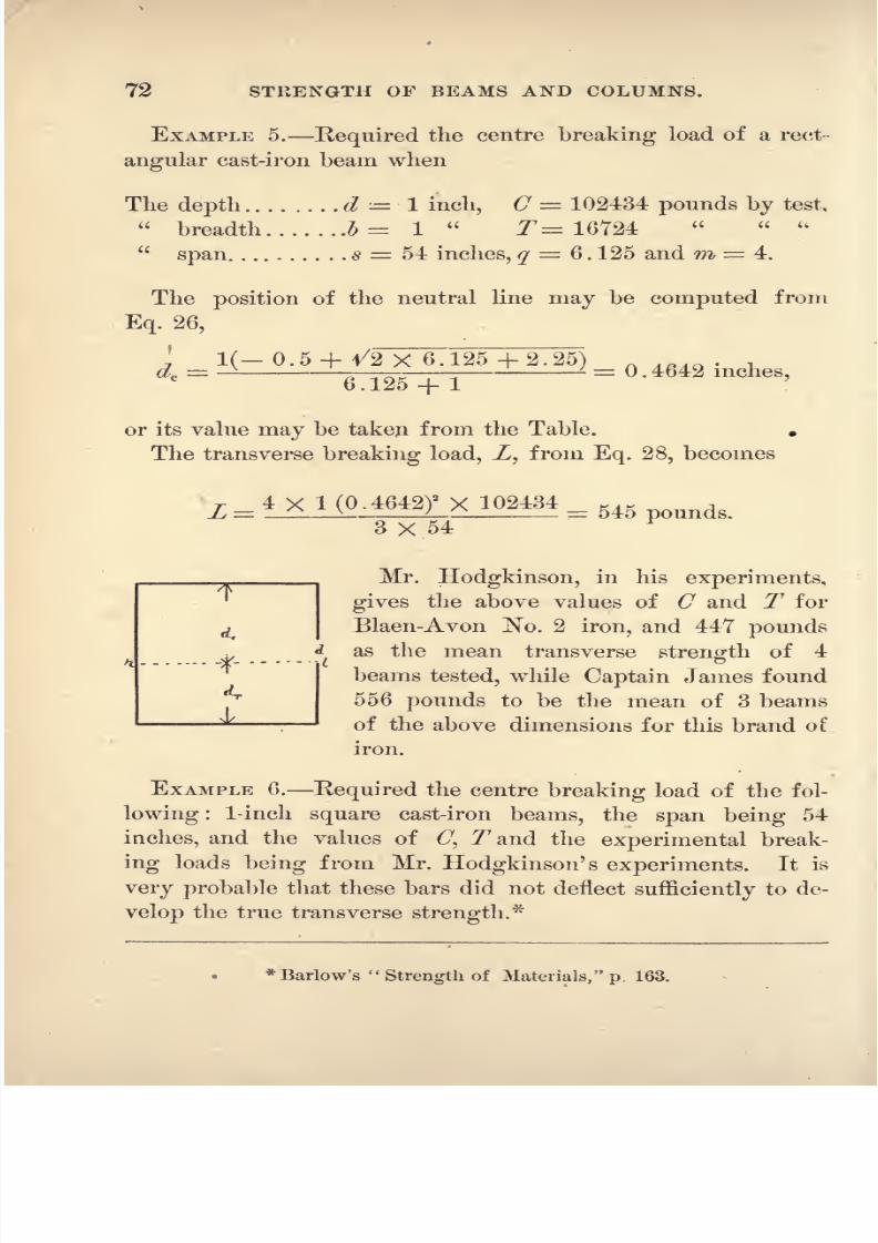
8/14/2019 A theoretical and practical treatise on the strength of beams and columns (1889)
http://slidepdf.com/reader/full/a-theoretical-and-practical-treatise-on-the-strength-of-beams-and-columns-1889 90/196
72 STRENGTH OF BEAMS AND COLUMNS.
EXAMPLE 5. Required the centre breaking load of a rect-
angularcast-iron
beam when
The depth d = 1 inch, C = 102434 pounds by test,
breadth b= 1
T= 16724
span s = 54 inches, q 6 . 125 and m = 4.
The position of the neutral line may be computed from
Eq. 26,
1(_ o.5 + 1/2 X 6.125+2.25) .
*< =6.125 + 1
or its value may be taken from the Table. .
The transverse breaking load, Z, from Eq. 28, becomes
L =.
6463 X 54
Mr. Hodgkinson, in his experiments,
gives the above values of C and T for
Blaen-Avon No. 2 iron, and 447 pounds
.,* as the mean transverse strength of 4
beams tested, while Captain James found556 pounds to be the mean of 3 beams
of the above dimensions for this brand of
iron.
EXAMPLE 6. Required the centre breaking load of the fol-
lowing : 1-inch square cast-iron beams, the span being 54
inches, and the values of(7,
77
and the
experimentalbreak-
ing loads being from Mr. Hodgkinson' s experiments. It is
very probable that these bars did not deflect sufficiently to de-
velop the true transverse strength.*
* Barlow's Strength of Materials, p. 163.

8/14/2019 A theoretical and practical treatise on the strength of beams and columns (1889)
http://slidepdf.com/reader/full/a-theoretical-and-practical-treatise-on-the-strength-of-beams-and-columns-1889 91/196
RECTANGULAR CAST-IRON BEAMS. 73
8/14/2019 A theoretical and practical treatise on the strength of beams and columns (1889)
http://slidepdf.com/reader/full/a-theoretical-and-practical-treatise-on-the-strength-of-beams-and-columns-1889 92/196
74 STEENGTH OF BEAMS AND COLUMNS.
SECTION III. HodgWmson Cast-iron Beams.
69. In this section we will consider the principles as if
applied to that class of cast-iron beams whose bottom or
tension flange is larger than its top or compressed flange,
though they are applicable to all other forms of flanged beams.
70. Mr. Hodgkinson's Experiments. Previous
to the year 1840, when Mr. Hodgkinson commenced his ex-
perimental investigation into the strength of materials, the
only metal beam that had been used in structures to any ex-
tent was the Inverted T, Fig. 17, and the Double T, Fig. 16,
in which the top and bottom flanges were equal in area.
Commencing his experiments with the equal flanged Double
T, he found that, by increasing the area of the lower or tension
flange by small amounts, he continued to increase the
transverse strength of the beam, his unit of measure and
standard of comparison being the quotient obtained from di-
viding the breaking load by the area of the section of the
beam expressed in inches, and that this continued to increase
until he had reached the point where the tension flange was
about six times the area of the compressed flange ; increasing
it to a greater ratio he found that the transverse strength per
square inch of section began to decrease. Experimenting with
cast-iron, in which the ratio of C to jT, or the crushing to the
tensile strength, was aboutsiae,
he recommended that the ten-
sion flange should have six times the area of the compressed
flange,in order to obtain the greatest transverse strength per
square inch of section. But subsequent iifvestigators, experi-
menting with cast-iron possessing greater tenacity, or a less
ratio of C to T than that used by Mr, Hodgkinson, found the
greatest strength with a lower ratio of extended to compressed
flange than that recommended by him. The reason for this
will be apparent when the formulas for the strength of these
beams are examined.

8/14/2019 A theoretical and practical treatise on the strength of beams and columns (1889)
http://slidepdf.com/reader/full/a-theoretical-and-practical-treatise-on-the-strength-of-beams-and-columns-1889 93/196
HODGKINSON CAST-IRON BEAMS. 75
71. Neutral Line. When the neutral line is not situ-
ated within the tension flanges, its position may be approxi-
mately computed from Eq. 36, page 42. Should the neutral
line lie within the tension flange, its position may be accu-
rately computed from Eq. 30, or from the methods given in
Probs. 1 and 2, page 43, when the transverse load and either
the compressive or tensile strength has been determined from
experiments. ___________
'M-ET
~~1
72. Transverse Strength. The '
_Ttransverse strength of the Hodgkinson or Af
of any beam having flanges at the top .v
and the bottom may be computed from . \either Eq. 37 or 38, as may be most con- f^
venient.
EXAMPLE 8. Required the centre breaking load of a Hodg-kinson cast-iron beam when
The depth of the beam d= 5.125 ins., C = 96000 Ibs.,
breadth of the web I = 0. 34 T = 16000
top flanges, ^ = 1.22
q = 6
depth
d,= 0.315
s = 54 ins.
bottom d,= 0.56
m = 4.
breadth b, = 4.83
Neutral Line. Our formula 36, giving the position of the
neutral line approximately only, places it in each case a little
too near the tensionflange.
In this example it locates it
within the tension flange, and we will assume that it coin-
cides with its upper line, or
dc = 4 .565 and dT = 0.56.
From Eq. 37 the transverse breaking load becomes
_ 0.34 (4.565)3
+1.22 (0.315)2(3x4.565-2X0.315) _
3X4565X54~
The tension area being continuous from the neutral line to the
T
8/14/2019 A theoretical and practical treatise on the strength of beams and columns (1889)
http://slidepdf.com/reader/full/a-theoretical-and-practical-treatise-on-the-strength-of-beams-and-columns-1889 94/196
76 STRENGTH OF BEAMS AND COLUMNS.
bottom of tlie beam, Eq. 28, page 38, can be used to compute
the load from tlie tensile strength T, in which Z> = Z> + 62of
this example.
L = 4X5.17X0.56 (2X5.125+4.565) 16000 _3X54
These two values of L, not being identical in numerical value,
our assumed position for the neutral line must have been a
little too low down in the section for exact equilibrium.
The above described beam was one of the series of beams
that was used by Mr. Hodgkinson to determine the section
of greatest strength. Its transverse breaking load was, by
test, 16730 pounds.* The value for T that we use was also
determined from experiment ;the ratio was supposed to be
O -r-
T = 6. In this series of beams the neutral line of
rupture was continuously lowered in the section, from pro-
gressively increasing the area of the tension flange until it
finally reached the upper surface of thisflange.
EXAMPLE 9. Required the centre breaking load of a Hodg-kinson Cast-Iron Beam (Fig. 15), when
The depth of the beam d = 14.0 ins., C = 75983 Ibs. by test,
breadth of the web b= 1.0 213815
top flanges d\ = 1.0
q = 5.5,
depth
b,= 2.5 = 16 feet,
bottom flanges d* 1.75 m = 4.
breadth
....&= 11.00
From Eq. 36 the position of the neutral line becomes
, 1X14+^12X14X11X1.75 (5.5+ 1)+ (1X14)* (4*5 5+5)
2X1(5.5+ )-= 13.5ms.,
which is within the tension flanges, assuming dc
- 14 1.75 =12.25.
* Barlow's Strength of Materials, p. l
r
8/14/2019 A theoretical and practical treatise on the strength of beams and columns (1889)
http://slidepdf.com/reader/full/a-theoretical-and-practical-treatise-on-the-strength-of-beams-and-columns-1889 95/196
HODGKINSON CAST-IRON BEAMS. 77
From Eq. 37 the breaking load, Z, becomes
_ . .)* (3X12.25-2X1) _3X12.25X12X16
From the tensile strength, T, and Eq. 28, L becomes
L = JAl2 >< 1-rcPX M + l&gg = 80109 Ib,
From this near identity of values for Z we conclude that our
assumed position for the neutral line was very near the correct
position.
Two of these beams were constructed of Calder No. 1 cast-
iron, and broken with centre loads of 73920 and 76160 pounds
respectively by Mr. Owens, Inspector of Metals for the British
Government.* The values of C and T were determined by
Mr. Hodgkinson for this brand of iron. The bottom table
contained six times the area of the top table, as recommended
by Mr. Hodgkinson.
These beams broke with the deflections l//
.87 and 2 .0 re-
spectively, and the full strength of the section was thus
developed by the transverse load.
The following statement gives the proportion of the load
sustained by each member of the transverse section and the
proportion of the area that it occupied :
Load. Area.
Compressed Flanges ............ 2.3 7.0 per cent.
Web ............. 47.7 34.3
Extended ............. 4.2 5:0
Flanges ........... 45.8 53.7
100.0 100.0
The web extends through the total depth of the beam.
* Box's Strength of Materials, p. 202.

8/14/2019 A theoretical and practical treatise on the strength of beams and columns (1889)
http://slidepdf.com/reader/full/a-theoretical-and-practical-treatise-on-the-strength-of-beams-and-columns-1889 96/196
78 STRENGTH OF BEAMS AND COLUMNS.
73. To Design a Hodgkinsoii Beam. The
formula required in designing a Uodgkinson beam will be
found in Art. 42, page 44.
SECTION IV. Double T and Box Cast-iron Beams.
74. The Neutral Line. The position of the neutral
line may be approximately computed from Eq. 36, page 42,
by giving the letters of the formula their definitions in Art.
44.
75. Transverse Strength. The Transverse Strength
,.. ,
y.. may be computed from Eqs. 37 and 38,I
I, ,
^JI giving the letters their definition in Art.
* i44'
. _.x' EXAMPLE 10. Required the centre
|i i breaking load of a Hollow Rectangular
\y\ Cast-Iron Beam whose outside dimensioni I
is 3 .125 X 3 .125, inside 2 .375 X
2 .375, thickness of metal all around 0.375, when
The depth of the beam d = 3 .125 C = 84000 Ibs.
breadth
sides b = 2 X 0 .375 T 14000
top .b,= 2
7/
.375 q=
6,
depth
d,= 0^.375 s = 6 feet,
bottom .. .d9= 0 .3Y5 m = 4.
breadth ...ft, = 2 .375
The position of the neutral line dcfrom Eq. 36 becomes
3.125X0.75+ 4/12X3.125 X 0.75 X 2.375 (6+1)+ (3. 125+0/75)2
(4x6+5)=
2X0.75(6 + )
1 .965.

8/14/2019 A theoretical and practical treatise on the strength of beams and columns (1889)
http://slidepdf.com/reader/full/a-theoretical-and-practical-treatise-on-the-strength-of-beams-and-columns-1889 97/196
DOUBLE T AND BOX OAST-IKON BEAMS. 79
The breaking load from Eq. 37 becomes
0.75 (1.965)* +2.375 (0.375)' (3X 1.965-2X 0.375)X4x84000_5760
3 X 1.965 X 12X6lbs
and from the tensile strength T7
,and Eq. 38, L becomes
L = 5178 pounds.
In the investigations preliminary to the construction of the
Menai Straits Tubular Bridge, Mr. Stephenson broke this
beam with 5387 pounds.*
76. To Design a Double T and Hollow Rectangular Cast-
iron Beam. This may be done by using the formula and
directions given in Art. 47, page 48.
* Britannia and Conway Tubular Bridges, p. 429.

8/14/2019 A theoretical and practical treatise on the strength of beams and columns (1889)
http://slidepdf.com/reader/full/a-theoretical-and-practical-treatise-on-the-strength-of-beams-and-columns-1889 98/196
80 STRENGTH OF BEAMS AND COLUMNS.
SECTION Y. Circular Cast-Iron Beams.
7 7 . Neutral Line. Table of positions of the neutral line
in Circular Cast-Iron Beams and factors for use in Eqs. 76 and 77.
Ratio of Crushingto Tenacity, or
C -t- T = q

8/14/2019 A theoretical and practical treatise on the strength of beams and columns (1889)
http://slidepdf.com/reader/full/a-theoretical-and-practical-treatise-on-the-strength-of-beams-and-columns-1889 99/196
CIRCULAR CAST-IRQ]* BEAMS. 81
From this Table the position of the neutral line is obtained
by placingfor
d, the diameter in inchesand computing the product indicated.
78. The Transverse Strengthof Circular Cast-Iron Beams may be ac-
curately computed from either Eq. 74- or
75, but as this involves a tedious calcu-
lationEq. 76 or 77 will give results, practically exact,
much less labor.
EXAMPLE 11. Required the centre breaking load of a
cular Cast-Iron Beam, when
The diameter d = 2 .0, C = 95200 pounds computed, Ex. 2,
span s 20 .0, T = 26569
by test,
m=4, q = 3.58.
The values of the factors fc andyT ,obtained by interpolation
from the Table, page 80, and substituted in Eqs. 76 and 77,
give
T 4 (I)
3
0.577 X 95200 1AOQflL v ; = 10986 pounds.20
Major Wade, in his experiments, broke this beam with
11112 pounds.
EXAMPLE 12. Required the centre breaking load of a Cir-
cular Cast-Iron Beam when
The diameter., .d 2 .42, C = 95200 Ibs. computed, Ex. 2,
span s = 20 .0, T = 26569
by test,
m =4, q 3.58.
/T.= 2.065 from the Table, which, substituted in Eq. 77, gives
26569

8/14/2019 A theoretical and practical treatise on the strength of beams and columns (1889)
http://slidepdf.com/reader/full/a-theoretical-and-practical-treatise-on-the-strength-of-beams-and-columns-1889 100/196
82 STRENGTH OF BEAMS AND COLUMNS.
Major Wade broke four beams of the above dimensions with
18141, 20419, 1999T and 18225 pounds respectively, the
mean strength being 19198 pounds.
EXAMPLE 13. Required the centre transverse elastic limit
load of a Circular Cast-Iron Beam, when
The diameter . .d T.129, C = 20000 pounds by test,
span s = 20 .0, T = 17000
m = 4, q = 1.111.
The value of /T= 1.1818 from the Table, page 80, substi-
tuted in Eq. 77, gives
T4 (0.5645)' 1.1818 X 17000L-- - = 1062 pounds.
2i()
The elastic limit load, of the two of these beams that were
tested, was 1130 pounds each, the values of C and T being the
mean of three tests, as given in the United States Government
Eeport of the Tests of Iron and Steel for 1884.*
EXAMPLE 14. Required the centre breaking load of the
Circular Cast-Iron Beam whose elastic limit load was com-
puted in Example 13, when
C = 100700 pounds by test, /T = 2.0333 from the Table,
T= 29400 q-= 3.422.
From Eq. 77 we have
r 4 (0.5645)3
2.0333 X 29400L - - = 2131 pounds.
The breaking load of the two beams described in Example13 was 2118 and 1795 pounds respectively.
79. Movement of the Neutral Line. In the Cir-
cular Cast-Iron Beam, Example 13, the depth of the neutral
* Senate Ex. Doc. No. 35 -49th Congress, 1st Session, p. 284.

8/14/2019 A theoretical and practical treatise on the strength of beams and columns (1889)
http://slidepdf.com/reader/full/a-theoretical-and-practical-treatise-on-the-strength-of-beams-and-columns-1889 101/196
CIECULAE CAST-IKON BEAMS. 83
line below tlie compressed surface at the elastic limit was,
from the Table, page 80, dc = OV7853 in Example 14, at the
instant of rupture, dc= 0 .5846
; hence, as the loading pro-
gressed, the neutral line moved upward, or from the tension
side toward the compressed side of the beam.
8O. Relative Strength of Circular and SquareCast-iron Beams.
CASE I. When the circle is inscribed within the square.The relation required is given in Eq. 83.
EXAMPLE 15. Required the relation between the transverse
strength of a square and the inscribed circular cast-iron beam
when C -r- T = 5.
/ = 0.5 from Table, page 71,/c = 0.4584 from Table, page 80.
3X/C _3X0.4584
8/a
'
8 X (0.5)'
. . Strength of Circle Strength of the Square X 0.6876.
EXAMPLE 16. Required the centre breaking transverse load
of the circular beam inscribed within the square, from the
tested strength of the square beam, when
The side of the square d = 2 .01, q = 3.58,
diameter of the circle d= 2 .01,/c= 0.577 from the Table,
span a = 20 .0,/= 0.561
With these values Eq. 83 becomes
3 X/e = 3 X 0.577?
8 X /* 8 (0.561)*
~
Actual b'k'g load square beam, Maj. Wade's tests, 16172 Ibs.
circular 11112
Comp'd =16172X0.687 = 11110
CASE II. When the square is inscribed within the circle.
The relation will be given by Eq. 84.
EXAMPLE 17. Required the relation between the strength

8/14/2019 A theoretical and practical treatise on the strength of beams and columns (1889)
http://slidepdf.com/reader/full/a-theoretical-and-practical-treatise-on-the-strength-of-beams-and-columns-1889 102/196
84 STRENGTH OF BEAMS AND COLUMNS.
of the circular and its inscribed square beam, when C -f- jT= 5.
/ = 0.5 from the Table, page Tl,/c = 0.4584 from the Table,
page 80.
.
3/c =3 X 0.4584
'
2.8271/a
2.8271 (0.5)
2
. . Strength of the Circle = /Strength of the Square X 1.945.
CASE III. When the circular is
equalin area to that
ofthe square beam.
The relation will be given by Eq.. 85.
EXAMPLE 18. Required the relation between the transverse
strength of the circular and the square beam, when their areas
are equal and C -f- T = 5.
/= 0.5 from the
Table, page 71,/c
= 0.4584 from theTable,
page 80.
.3/e 3X0.4584
'
5.564/2
~
5.564 X (0.5)
2
.
'
. Strength of the Circle = Strength of the Square X 0.987.
EXAMPLE 19. Required the centre breaking load of a Circu-
lar Cast-iron
Beam fromthat of the
square beamof
equal area,when
The side of the square d= 1 .01, q 5.091,' '
diameter of the circle d = 1 . 145, /c= 0.4562, from the Table, page 80,
span * = 60 .0 /= 0.496
71.
With these values Eq. 85 becomes
3 X 0.45625.564 (0.496)
51.
Mean b'k'g I'd of 4 of these square beams from Mr. Barlow's tests,* 519 Ibs.,
of the circular beam from Mr. Barlow's tests, 519 pounds,
Comp'd = 519 X 1 = 519 pounds.
* Barlow's Strength of Materials, p. 152.

8/14/2019 A theoretical and practical treatise on the strength of beams and columns (1889)
http://slidepdf.com/reader/full/a-theoretical-and-practical-treatise-on-the-strength-of-beams-and-columns-1889 103/196
HOLLOW CIRCULAR CAST-IRON BEAMS. 85
SECTION VI. Hollow Circular Cast-Iron Beams.
81. Neutral Lliie.
Ratio of Crushingto Tenacity, or
C *- T = q.
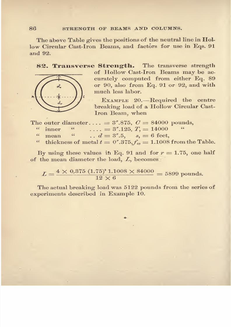
8/14/2019 A theoretical and practical treatise on the strength of beams and columns (1889)
http://slidepdf.com/reader/full/a-theoretical-and-practical-treatise-on-the-strength-of-beams-and-columns-1889 104/196
86 STRENGTH OF BEAMS AND COLUMNS.
The above Table gives the positions of the neutral line in Hol-
low Circular Cast-Iron Beams, and factors for use in Eqs. 91
and 92.
82. Transverse Strength. The transverse strength
^^ of Hollow Cast-Iron Beams may be ac-
curately computed from either Eq. 89
or 90, also from Eq. 91 or 92, and with
much less labor.
EXAMPLE 20. Required the centre
breaking load of a Hollow Circular Cast-
iron Beam, when
The outer diameter. . . . = 3 .875, C = 84000 pounds,
inner
. . . .= 3M25, T,
= 14000
mean . . d = 3 .5, *, = 6 feet,
thickness of metal t = 0 .375,/c ,
= 1.1008 from the Table.
By using these values in Eq. 91 and for r = 1.75, one half
of the mean diameter the load, Z, becomes
L = 4X0.375(1.75)- 1.1008X84000 = 5g99
12 X 6
The actual breaking load was 5122 pounds from the series of
experiments described in Example 10.

8/14/2019 A theoretical and practical treatise on the strength of beams and columns (1889)
http://slidepdf.com/reader/full/a-theoretical-and-practical-treatise-on-the-strength-of-beams-and-columns-1889 105/196
CHAPTEE V.
WROUGHT-IRON AND STEEL BEAMS.
SECTION I. General Conditions Wrought-iron.
83. Compressive Strength. Crushing. Wrought-
iron, when subjected to pressure, increases its area so rapidly
that it is impossible to determine with precision its crushing
strength or that intensity of pressure that corresponds to the
tenacity. Its value, per square inch, as quoted by the various
writers,varies from 30000 to 90000
pounds per squareinch.
The great pressure to which wrought-iron is subjected when
rolled into sheets and eye-beams causes it to lose a portion of
its ductility and increase its crushing strength. The crushing
strength of Swedish bar-iron, computed from Mr. Kirkaldy's
experiments (Example 21), is 60000 pounds per square inch,
while the crushing strength of wrought-iron when rolled into
eye-beams, computed from Mr.Fairbairn's
experiments,is
86466 pounds per square inch (Example 22).
Elastic Limit. The compressive elastic limit of wrought-
iron in bars may be taken at 30000 pounds per square inch.
The computed value of the compressive elastic limit for rolled
eye-beams is 631 TO pounds (Example 31),from data furnished
by the Phoenix Iron Company's experiments.
84. Tensile Strength. Tenacity. When wrought-iron
is subjected to a tensile strain before rupture takes place,it in-
creases in length from 15 to 20 per cent, and contracts in area
at the fractured section about 25 per cent. Its tenacity ranges
in value from 50000 to 65000 pounds per square inch; wrought-
iron diminishes in tensile strength when rolled into sheets.

8/14/2019 A theoretical and practical treatise on the strength of beams and columns (1889)
http://slidepdf.com/reader/full/a-theoretical-and-practical-treatise-on-the-strength-of-beams-and-columns-1889 106/196
88 STRENGTH OF BEAMS AND COLUMNS.
Elastic Limit. The tensile elastic limit of bar-iron is about
one half of its tenacity ;the mean may be considered to be
30000 pounds per square inch.
STEEL.
85. Compress ve Strength. Crushing. In deter-
mining its crushing strength, the same difficulty mentioned in
determining
that of
wrought-iron
is encountered;
its value, as
given for the different kinds, varies from 100000 to 340000
pounds per square inch.
The compressive elastic limit of steel ranges from 20000 to
60000 pounds per square inch.
86. Tensile Strength. The tenacity of.steel is greater
than that of any known material;
it ranges in value from
60000 to 160000 pounds per square inch.
87. To Compute the Compress ve Strength.Formula 31, page 40, and Eq. 79, page 58, may be used to great
advantage to determine the crushing strength for such materials
as wrought-iron and steel whose resistance to crushing cannot
be readily determined in the usual manner, because they in-
crease their area so rapidly, under direct pressure, when ap-
plied to small test specimens, that no precise determination of
their strength can be made. The deflection of the beam, how-
ever, must be sufficient to allow the neutral line to move to the
position required for rupture of the fibres by the cornpressive
and tensile strains at the same instant, for the reason given in
Art. 24.
EXAMPLE 21. Required the Crushing Value of C for
wrought-iron, from the tensile strength and the centre trans-
verse breaking down load, when
The depth d = 2.0 inches, T= 42133 pounds, by test,
breadth... & = 2.0
L = 13338
span s = 25.0 m = 4.
8/14/2019 A theoretical and practical treatise on the strength of beams and columns (1889)
http://slidepdf.com/reader/full/a-theoretical-and-practical-treatise-on-the-strength-of-beams-and-columns-1889 107/196
GENERAL CONDITIONS. 89
The required position of the neutral line from Eq. 30 is
j3 X 2 ^9X4X2 (2)
2 42133- 12 X 13338 X25_T~
2 4 X 4 X 2 X 42133'554
'
. . dc= 2 - 0.554 = 1.446 inches and C from Eq. 31.
^_3 X 13338 X 25 _4
X 2(1.446)*
This example is taken from Mr. Kirkaldy's experiments.*
By direct .pressure he determined C 84890 pounds, when
the length= 2 diameters, and 0= 148840 pounds, when the
length 1 diameter of the test specimen. Our computation of
the value of C is made under the hypothesis that the tensile
strain in the
experimentwas
sufficiently intense, thoughit did
not actually fracture the beam.
EXAMPLE 22. Kequired the Crushing Yalue of C for rolled
wrought-iron from the tensile strength and the centre trans-
verse breaking load of a rolled wrought-iron T beam.
The depth of the beam d 3 .0, T 57600 pounds mean
for British bar-iron.
The breadth of the web b = 0 .5, L = 2690 pounds, from
Mr. Fairbairn's test.f
The breadth of the compressed flanges &, 2 .5, m = 4.
The deptli
d,=
0 .375, a = 10 ft.
The position of the neutral line, the beams having no bottom
flanges, from Eq. 30, becomes
d, =3 X 8
_.4/9~X 4 X 0.5 (3)
2 57600 - 12 X 2690 X 120 _., Q6
.
V 4 X 4 X 0.5 X 57600
* Barlow's Strength of Materials, p. 256.
t Box's'
Strength of Materials, p. 214.

8/14/2019 A theoretical and practical treatise on the strength of beams and columns (1889)
http://slidepdf.com/reader/full/a-theoretical-and-practical-treatise-on-the-strength-of-beams-and-columns-1889 108/196
90 STRENGTH OF BEAMS AND COLUMNS.
arid from Eq. 37,
L = 2690 =0.5 (04)3 +
EXAMPLE 23. Required the Crushing Strength of certain
steel madebj
the Otis Iron and Steel Co., of
Cleveland,Ohio, from the centre breaking load of a circular beam when
The diameter = 1 .129, T 83500 pounds mean of 10 tests,
span 20 .0, Z = 3860 one test.
From Eq. 78 we have
*
~~
4 (0.5645)3 83500
From the Table, page 100, q 1.2122 for this value of /T,
and from Eq. 79,
C = 1.2122 X 83500 101218 pounds.
This example is taken from the United States Government
Report of Tests of Iron and Steel, at Watertown Arsenal, for
1885.*
88. To Compute the Tensile Strength. The
tensile strength may be computed from test values of C and
the load L in rectangular beams by means of Eq. 33, having
first ascertained the position of the neutral line from Eq. 32,
and for circular beams from Eqs. 80 and 81, page 58.
EXAMPLE 24. Required the Tensile Strength of Burden's
Best
wrought-iron from the centre breaking load of a cir-
cular beam when
* Senate Ex. Doc. No. 36 49th Congress, 1st Session, p. 690.

8/14/2019 A theoretical and practical treatise on the strength of beams and columns (1889)
http://slidepdf.com/reader/full/a-theoretical-and-practical-treatise-on-the-strength-of-beams-and-columns-1889 109/196
GENERAL CONDITIONS. 91
The diameter ....... d = 1 .25, C 64500 pounds assumed,
span........... * = 12 .0, Z = 6000
by test.
From Eq. 80 we have
6000 X 12_
'~~
4 (0.625)' 64500
From the Table, page 100, q= 1 for the above value of yc ,
from Eq. 81,
T =^>2?
= 64500 pounds.
This beam was broken at the Rensselaer Polytechnic In-
stitute in November, 1882, as given by Professor W. H. Burr.
89. Transverse Strength of Wrought-
Iron.The elastic limit load is technically called the breaking load
for wrought-iron beams, as from its position in the section of
the beam where fracture should take place from the fibre
strains being greatest,it cannot undergo the change of form
required before its fibres can befractured /this breaking load
may be computed from the tensile and compressive elastic
limit coefficients of wrought-iron.
The breaking-down load. While wrought-iron in beams
cannot be broken transversely by rupturing its fibres, yet there
is an intensity of the transverse lo*ad at which it does not
appear to be able to offer any further resistance to the action
of the bending load; this load may be called the breaking-
down load;
in wrought-iron beams it is about twice the
technical breaking or elastic limit load.
Wrought-iron when rolled into T beams may become
sufficiently hard and unyielding from the intense pressure re-
quired to make it fill the rolls, that it will offer sufficient
resistance to actually fracture the fibres by the tensile strain, as
in Example 22.

8/14/2019 A theoretical and practical treatise on the strength of beams and columns (1889)
http://slidepdf.com/reader/full/a-theoretical-and-practical-treatise-on-the-strength-of-beams-and-columns-1889 110/196
92 STRENGTH OF BEAMS AND COLUMNS.
9O. Transverse Strength of Steel. As in the
case of wrought-iron beams the elastic limit load of steel
beams is technically called the breaking load.
The breaking-down load of steel beams is about fths of the
elastic limit load.
SECTION II. Rectangular Wrought-iron and Steel Beams.
91. Neutral Line. The position of the neutral line
may be computed from either formula 25 or 26. From Eq.
25 the position has been computed for the different values of
(7 -r- Tq,
that are required in wrought-iron and steel rect-
angular beams, and the results tabulated below for reference.
Table of Positions ofthe
Neutral Line in RectangularWro^lght-Iron and Steel Seams :
Ratio of Crushingto Tenacity, or
C -*- T = q.

8/14/2019 A theoretical and practical treatise on the strength of beams and columns (1889)
http://slidepdf.com/reader/full/a-theoretical-and-practical-treatise-on-the-strength-of-beams-and-columns-1889 111/196
8/14/2019 A theoretical and practical treatise on the strength of beams and columns (1889)
http://slidepdf.com/reader/full/a-theoretical-and-practical-treatise-on-the-strength-of-beams-and-columns-1889 112/196
94 STRENGTH OF BEAMS AND COLUMNS.
tions for q= 1 and q
=0.9, for which dc
= 1.58. With
these values the required load, Z, becomes from Eq. 27,
T 4 X 2(1.58)2
22631= ~
3X25 r = P imds-
Mr. Kirkaldy determined, experimentally, that the centre
breaking load of this beam was between 6000 and 6500
pounds, and that the elastic limit values of O and T were as
given above.
The position of the neutral line for the l>reaking-down
load of this beam (Example 21) was 1 .446 below the top or
compressed side of the beam, and as the loading progressed
it must have moved upward from its position at the elastic
limit, 1 .58, to 1 .446, its position with the breaking-down
load.
The deflection with 6000 pounds was 0 .318, and with 6500
0 .506;
it only required 0 .46 to fully develop the elastic
fibre strain limits.*
EXAMPLE 21. Required the centre transverse elastic limit
load of a Rectangular Steel Beam, when
The depth d= 1 .15, C = 48000
pounds bytest,
breadth I = 1 .75, C = 52000
span s = 25 .0, q=
0.923, and m 4.
The position of the neutral line, computed from Eq. 25, or
taken from the Table by proportion, is
dc= 1 .3S67 and </T
= 0.3633.
The required load, Z, from Eq. 21, becomes
T4 X 1.15 (1.3867)* 48000
=
~ 3 X25 pounds.
* Barlow's Strength of Materials, p. 256.

8/14/2019 A theoretical and practical treatise on the strength of beams and columns (1889)
http://slidepdf.com/reader/full/a-theoretical-and-practical-treatise-on-the-strength-of-beams-and-columns-1889 113/196
RECTANGULAR WROUGHT-IRON AND STEEL BEAMS. 95
Mr. Kirkaldy determined by experiment that the elastic
limit load of each of 4 of these beams was between 8000 and
9000 pounds, and that the values of C and T were as
given.
The deflection with 8000 pounds was 0 .476, and it only
required 0 .3633 to develop the elastic compressive and tensile
fibre strain limits at the same instant.*
EXAMPLE 28. ^Required the breaking-down load of the
beam described in Example 27, when
C = 159582 pounds by test, q=
2.3,
T = 69336 m = 4.
For the position of the neutral line from Eq. 25 or from the
Table,
d = 1 .121 and d, = 0 .629.
The breaking-down load, .Z, becomes from Eq. 27,
T4 X 1.75 (1.121)
2
159582L = - ~ - - = 18716 pounds.
o X -aO
The mean breaking-down load of 4 cf these beams was
16477 pounds from Mr. Kirkaldy's experiments. The upwardmovement of the neutral line is seen in these Examples, in
Example 27, dc= l
//
.3867 and in Example 28, dc= 1 .121.
Barlow's Strength of Materials, p. 253.

8/14/2019 A theoretical and practical treatise on the strength of beams and columns (1889)
http://slidepdf.com/reader/full/a-theoretical-and-practical-treatise-on-the-strength-of-beams-and-columns-1889 114/196
96 STRENGTH OF BEAMS AND COLUMNS.
SECTION III. Double T, Rolled Eye-Beams and HollowRectangle or Box, Wrought-Iron and Steel Beams.
93. Neutral Line. The neutral lines in these wrought-
iron and steel beams are so near the bottom or tension side of
the beam that their positions cannot be computed from ap-
proximate formulas, and the exact formula is too complicated
to be useful in practice. Before beams of these sections are
manufactured, its position should be assumed and a sufficient
area of the metal placed above and below the assumed neutral
line to insure equilibrium from the known values of the crush-
ing and tensile strength of the material.
In most practical examples of these beams the neutral line
is located within the tension flange, and its position can be
computed from Eq. 30, page 40, wrhen L the load and T the
tensile strength have been determined experimentally, or by
the methods given in Problems I. and II., page 43.
94. Transverse Strength . When the position of
the neutral line is known the transverse strength may be com-
puted from either Eq. 37 or 38, that were deduced for the
transverse strength of the Hodgkinson beam, giving the letters
of the formulas the meaning defined in Art. 44, page 47.The transverse strength of both the Tee and Double-
Headed Railroad Rails may be very accurately computed from
the above formulas, although they are partly bounded in
outline by curved lines. The web must extend from the
bottom to the top of the rail, and an equivalent in area right
line section must be formed for the metal that remains in both
the base and head of the rail, which will enable the formulasto be applied to these forms of beams.
95. Double T beams loith tension and compression
jlanges unequal in area.
EXAMPLE 29. Required the centre elastic limit load of a
Wrought-Iron Rolled Double T Beam, when
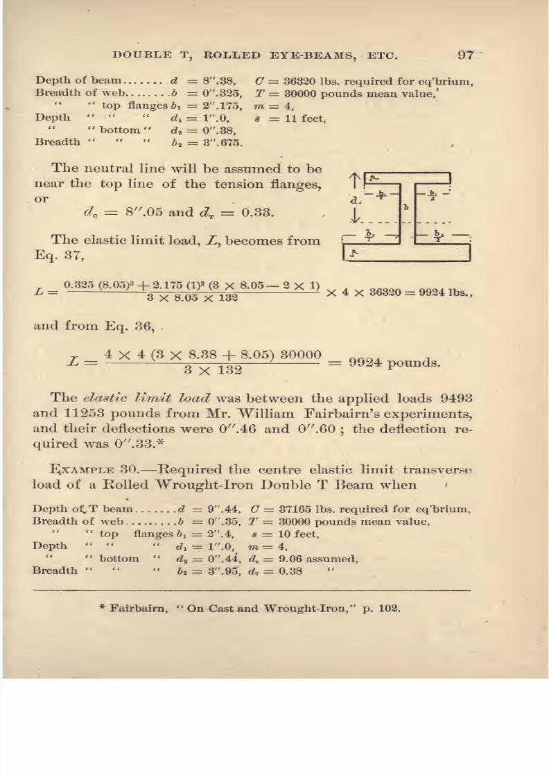
8/14/2019 A theoretical and practical treatise on the strength of beams and columns (1889)
http://slidepdf.com/reader/full/a-theoretical-and-practical-treatise-on-the-strength-of-beams-and-columns-1889 115/196
DOUBLE T, EOLLED EYE-BEAMS, ETC. 97
Depth of beam : d = 8 . 38, C = 36320 Ibs. required for eq'brium,
Breadth of web b = 0 .325, T = 30000 pounds mean value,'
top flanges b l = 2 . 175, ra = 4,
Depth
di = 1 .0, s = 11 feet, bottom
dz = 0 .38,
Breadth
J a = 3 . 675.
The neutral line will be assumed to be
near the top line of the tension flanges,
or d, .
dc = 8/r
.05 and d,f = 0.33. I
The elastic limit load, Z, becomes from
Eq. 37,
_ 0.325(8.05)3+ 2.175 < ) (3 X 8.05- 2 X 1) _3~X~a05 X 132
yy/<54 lbs>'
and from Eq. 36,
T4 X 4 (3 X 8.38 + 8.05) 30000
3 X 132^9924 pounds.
The elastic limit load was between the applied loads 9493
and 11253 pounds from Mr. William Fairbairn's experiments,
and their deflections were 0 .46 and 0 .60;the deflection re-
quired was 0 .33.*
EXAMPLE 30. Required the centre elastic limit transverse
load of a Rolled Wrought-Iron Double T Beam when '
Depth otT beam d = 9 . 44, C = 37165 Ibs. required for eq'brium,
Breadth of web b = 0 .35, T = 30000 pounds mean value,
top flanges b l 2 . 4, * = 10 feet,
Depth
di - 1 .0, m=4,
bottom
da = 0 .44, dc= 9.06 assumed,
Breadth &2 = 3 . 95, dT = 0.38
*Fairbairn,
On Cast and Wrought-Iron, p. 102.

8/14/2019 A theoretical and practical treatise on the strength of beams and columns (1889)
http://slidepdf.com/reader/full/a-theoretical-and-practical-treatise-on-the-strength-of-beams-and-columns-1889 116/196
98 STRENGTH OF BEAMS AND COLUMNS.
With these values the load, Z, becomes from Eq. 28,
T4 X 4.3 X 0.38 (2 X 9.44 + 9.06) 30000
L =3 X 12 X 1<T- ^
and from Eq. 38,
0.35(9.06)3 + 2.4 (I)2
(3 X 9.06 - 2 X 1) , _, _. ._ ..
~^9766~xi2x~io~~
The elastic limit load was between the applied loads 14693and 16373 pounds from Mr. William Fairbairn's experiments,
and the deflection was 0 .35 and 0 .45 with these loads re-
spectively.*
In Examples 29 and 30 the tensile elastic limit has been
assumed to be 30000 pounds, the mean value for wrought-
iron, and from it the position of the neutral line has been
computed from Eq. 30,. and then the required value of C to
produce equilibrium.
rr96. Double T 'beams with tension
c T> j an^ compression flanges equal in area.
*---
**^
~ ~
1.
EXAMPLE 31. Required the centre
transverse elastic limit load of a Rolled
Wrought-Iron Eyebeam when
Depth of beam d = 9 .0, 63170 Ibs. required for eq'brium,
Breadth of web b = 0 .6, ^=30000 mean value,
top flanges &i = 4 .775, ra = 4,
Depth
di = 1 .0, s= 14 feet, bottom d.2 = 1 .0, dc
= 8 .2,
Breadth
5a = 4 .775, dT = 0 .8.
With these values the load, Z, becomes from Eq. 37,
L =^^ xa -' xl)>< 4 >< -
*Fairbairn,
On Cast and Wrought-Iron, p. 103.
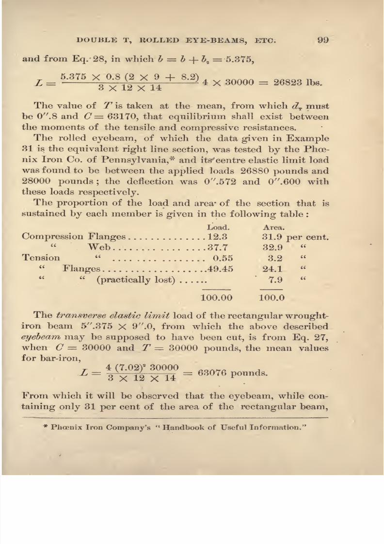
8/14/2019 A theoretical and practical treatise on the strength of beams and columns (1889)
http://slidepdf.com/reader/full/a-theoretical-and-practical-treatise-on-the-strength-of-beams-and-columns-1889 117/196
DOUBLE T, ROLLED EYE-BEAMS, ETC. 99
and from Eq. 28, in which b = I + \ = 5.375,
The value of T is taken at the mean, from which dv must
be 0 .8 and O= 63170, that equilibrium shall exist between
the moments of the tensile and compressive resistances.
The rolled eyebeam, of which the data given in Example
31 is the equivalent right line section, was tested by the Phoe-
nix Iron Co. of Pennsylvania,* and its'centre elastic limit load
was found to be between the applied loads 26880 pounds and
28000 pounds ;the deflection was
//
.5T2 and 0 .600 with
these loads respectively.
The proportion of the load and area* of the section that is
sustained by each member is given in the following table :
Load. Area.
Compression Flanges .............. 12.3 31.9 per cent.
Web ................ 37.7 32.9
Tension ................ 0.55 3.2
Flanges ...................49.45 24.1
(practically lost) ...... 7.9
100.00 100.0
The transverse elastic limit load of the rectangular wrought-
iron beam 5 .375 X 9 .0, from which the above described
eyebeam may be supposed to have been cut, is from Eq. 27,
when C = 30000 and T = 30000 pounds, the mean values
for bar-iron,
T4
(7.02)
2
30000,
on_L =3 X 12 X 14
: ~- 6S076 P Unds '
From which it will be observed that the eyebeam, while con-
taining only 31 per cent of the area of the rectangular beam,
* Phoenix Iron Company's Handbook of Useful Information.

8/14/2019 A theoretical and practical treatise on the strength of beams and columns (1889)
http://slidepdf.com/reader/full/a-theoretical-and-practical-treatise-on-the-strength-of-beams-and-columns-1889 118/196
100 STRENGTH OF BEAMS AND COLUMNS.
is able to sustain 42.5 per cent of its load, which is supposed
to be due to the elevation of the elastic limit during the pro-
cess of rolling, or the top of the beam must have been laid
with steel.
SECTION IY. Circular Wrought-Iron and Steel Beams.
97. Neutral Line. The position of the neutral line
in Circular Wrought-Iton and Steel Beams for the different
ratios of C -f- T = q required has been computed, also the
factorsf/c and/i for use in Eqs. 76 and 77, and tabulated be-
low for reference.

8/14/2019 A theoretical and practical treatise on the strength of beams and columns (1889)
http://slidepdf.com/reader/full/a-theoretical-and-practical-treatise-on-the-strength-of-beams-and-columns-1889 119/196
CIRCULAR WROUGHT-IRON AND STEEL BEAMS. 101
corresponding to the ratio C -r- T =q.
For ratios intermedi-
ate in value the position may be obtained by proportion.
98. Transverse Strength. This may be computedfrom either Eq. 74 or 75, but with much
less labor from Eq. 76 or 77, using the
values of fc and /*T given in the above
Table.
EXAMPLE 32. Required the centre
breaking or elastic limit load of a Circu-
lar Steel Beam when
The diameter d = 1 .129, C = 41160 Ibs. mean of four tests,
span s = 20 .0, T= 39200
ten
factor...m =4,
q
= 1.05.
The position of the neutral line and factor, f& becomes, by
proportion from the Table,
dc= 0.6912 X 1 .129 = 0.780, /c
= 1.132.
With these values the load, L, required becomes from Eq. 76,
T 4 (0.5645)* 1.132 x 41160L -^ - = 1676 pounds.
Z(J
From the United States Government Report of the Tests
of Iron and Steel for the year 1885,* the elastic limit load of
two of these beams that were tested was 1638 pounds with
the values of C and T as given in the Example.
EXAMPLE 33. Required the centre elastic limit load of a
cylindrical Phoenix pin supported at both ends when
* Senate Ex. Doc. No. 36-49th Congress, 1st Session, p. 690.

8/14/2019 A theoretical and practical treatise on the strength of beams and columns (1889)
http://slidepdf.com/reader/full/a-theoretical-and-practical-treatise-on-the-strength-of-beams-and-columns-1889 120/196
102 STRENGTH OF BEAMS AND COLUMNS.
The diameter. ... d= 2 .5, C = 30000
pounds
from tests,
span s = 24 .0, T = 30000
'
factor m =4, /c
= 1.1548 from the Table.
Then from Eq. 76 we have for the required load,
L -JW 1.1S48 X 30000
24
The elastic limit strength of this pin was 11000 pounds.
(Watertown Arsenal Report of Tests of Iron and Steel for
1881.)* The computed ultimate strength is 18795 pounds,
with and T = 50000 pounds, the recorded ultimate strength
is 20000 pounds.
In order that these wrought-iron pins should truly cross-
break, their deflectionshould not be less than 0.3024
d',
in the
above examples the ultimate deflection was l//
.278;while that
required for true cross-breaking was 0 .75, the recorded de-
flection with 18000 pounds was 0 .78.
A number of these pins,made of Phoenix and Pencoyd
iron, were tested with diameters ranging from 2J to 5 inches,
but the span was so short, in nearly all cases, that the tensile
fibre strain was not fully developed, causing thetransverse
elastic limit load to be not well defined and the ultimate load
to be larger than it should be. Though the computed elastic limit
loads do not differ very greatly from those determined by
tests, there is a very great difference between the computed
and experimental ultimate loads, the latter being the greater.
This series of tests illustrates the correctness of the state-
ment made in Art. 24, that the bending moment of the ap-
plied load at the inception of the deflection of a beam is held
in equilibrium by the moment of a purely compressive resist-
ance that is distributed over the section in an uniformly vary-
* House of Representatives Ex. Doc. No. 12, 1st Session, 47th Congress,
p. 171.

8/14/2019 A theoretical and practical treatise on the strength of beams and columns (1889)
http://slidepdf.com/reader/full/a-theoretical-and-practical-treatise-on-the-strength-of-beams-and-columns-1889 121/196
CIRCULAR WBOUGHT-IRON AND STEEL BEAMS. 103
ing strain. Test ISTo. 741, page 186, of the Report, was of
Phoenix iron 4 in diameter and 24 span. The bending
moment of the centre applied load is 6 L from Eq. 3, page 5,
and the moment of compressive resistance is the product of
the resultant (the area of the section by one half, (7,the elastic
limit compressive strength), by its lever-arm, f-6?,the distance
of the centre of gravity of the pressure wedge below the axis;
hence
3d . (V C
.
.
. L =
The observed elastic limit load was 48000pounds
with a
deflection of 0 .0585, but as no correction appears to have
been made for the settling of the beam on its bearings, we
may conclude that the beam was on the verge of true deflec-
tion with its transverse elastic limit load.
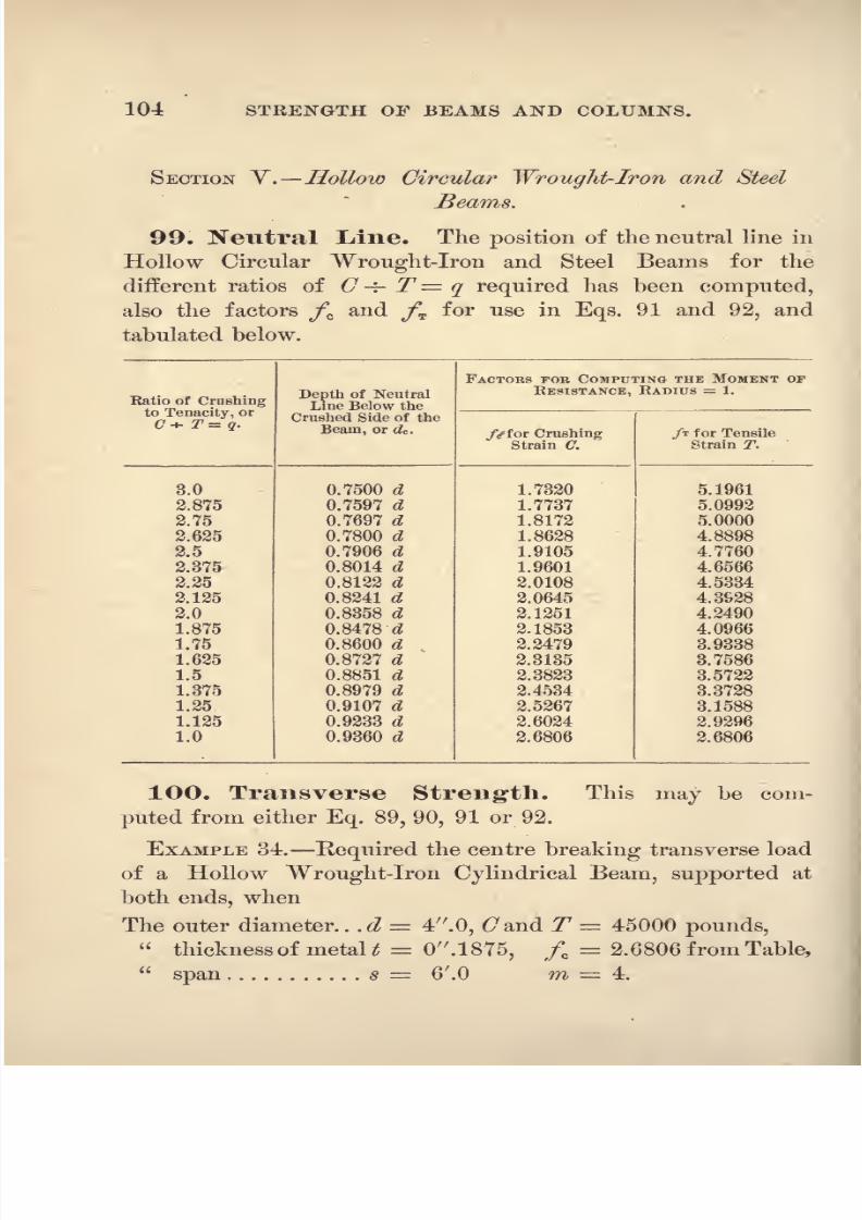
8/14/2019 A theoretical and practical treatise on the strength of beams and columns (1889)
http://slidepdf.com/reader/full/a-theoretical-and-practical-treatise-on-the-strength-of-beams-and-columns-1889 122/196
104 STRENGTH OF BEAMS AND COLUMNS.
SECTION Y'
.Hollow Circular Wrought-Iron and Steel
Beams.
99. Neutral Line. The position of the neutral line in
Hollow Circular Wrought-Iron and Steel Beams for the
different ratios of C -j- T= q required has been computed,
also the factors fG and fT for use in Eqs. 91 and 92, and
tabulated below.

8/14/2019 A theoretical and practical treatise on the strength of beams and columns (1889)
http://slidepdf.com/reader/full/a-theoretical-and-practical-treatise-on-the-strength-of-beams-and-columns-1889 123/196
WROUGHT-IRON AND STEEL BEAMS. 105
Then from Eq. 91 we have for the load,
T 4 (2)
2
2.6806 x 0.1875 x 45000L = -
t- 5076 pounds.
This tube failed suddenly with 5824 pounds. (From
The
Britannia and Conway Tubular Bridge, p. 435.)
8/14/2019 A theoretical and practical treatise on the strength of beams and columns (1889)
http://slidepdf.com/reader/full/a-theoretical-and-practical-treatise-on-the-strength-of-beams-and-columns-1889 124/196
CHAPTER VI.
TIMBER BEAMS.
101. The Compress ve and Tensile Strength.The great number of the different varieties of timber, and
the great variation in the strength of the timber that is
known in different parts of the globe by the same name,
render the determination of constants or mean values for Cand T for use in the computation of the strength of beams a
very difficult matter, and we find that much difference exists
between the constants that are given for the same timber bythe older and more recent experimenters ; especially is this the
case for the crushing strength. The former make C ~ Tless than 0.75 for all of the principal varieties, while the latter
make it greater than%inity.
The computed transverse strength of the beams broken bythe older
experimenters
from their constan
Ogives, practically,accurate results, or such as are within the limits of the varia-
tion in strength of the material, while those from the more
recent experimenters make their computed transverse strength
from twenty-five to one hundred per cent greater than their
experiments gave, which indicates that with improved testing
machines the more recent experimenters, such as Professor
Thurston,Laslet and
Hatfield,obtained their
crushing strengthat a point nearer the total destruction of the wood than the
older with machines having less power.
102. To Compute the Compressive and Ten-sile Strength. Crushing. From the fibrous character
of timber and its weak lateral adhesion it is difficult to de-

8/14/2019 A theoretical and practical treatise on the strength of beams and columns (1889)
http://slidepdf.com/reader/full/a-theoretical-and-practical-treatise-on-the-strength-of-beams-and-columns-1889 125/196
TIMBER BEAMS. 107
termine its crushing strength from direct pressure on small
specimens, or that intensity of crushing strain that holds its
tensile strength in equilibrium : this can be accurately com-
puted from Eqs. 31 and 79, when the breaking, transverse
and tensile strength have been determined from experiments.
EXAMPLE 35. Required the Crushing Strength of Teak-
wood from the known tensile strength and the centre trans-
versebreaking
load of arectangular
beam when
Depth. . .d=2.0 ins., T= 15000 Ibs. mean of Mr. Barlow's tests,
Breadth .5= 2.0 Z=938
Span . ... =Y.O feet, m=4.
The position of the neutral line becomes from Eq. 30,
d = 8X 2 - Ag
x4
x2
<
2)
2 1500 ~ 12
X8
X12
X7 = 035 ins2 Y
'
4 X 4 X 2 X 150QO
. . dc= 2.0 - 0.35 = 1.65 inches,
and the crushing value of C from Eq. 31,
From Mr. Hodgkinson's experiments C = 12100 pounds
for Teak.
Tensile Strength. This may be computed from Eqs. 32
and 33, and from Eqs. 80 and 81, when the transverse and
crushing strength have been ascertained from experiments.
RECTANGULAR WOODEN BEAMS.
1O3. Neutral Line. Table of positions of the neutral
line in rectangular sections of wood, and the mean ultimate
crushing and tensile strength of the different varieties of
timber.
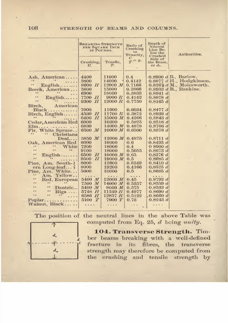
8/14/2019 A theoretical and practical treatise on the strength of beams and columns (1889)
http://slidepdf.com/reader/full/a-theoretical-and-practical-treatise-on-the-strength-of-beams-and-columns-1889 126/196
108 STRENGTH OF BEAMS AND COLUMNS.

8/14/2019 A theoretical and practical treatise on the strength of beams and columns (1889)
http://slidepdf.com/reader/full/a-theoretical-and-practical-treatise-on-the-strength-of-beams-and-columns-1889 127/196
TIMBER BEAMS. 109
means of either Eq. 27 or 28, as the rectangular is the form
that is principally used in wooden beams.
EXAMPLE 36. Required the uniformly distributed breaking
load of an American White Pine Rectangular Beam, when
The depth d 14 .0, C 5000 pounds mean of tests,
breadth....I = 6 .0, T = 10000
span s = 28'. 0, m =8, Art. 34, and q
= 0.5.
The position of the neutral line from the Table is
dc0.8685 X 14 12.16 inches,
and the breaking load from Eq. 27 becomes
8X6 (12.16)' 5000L -3X12X28
=
The Table in Trautwine's Engineers' Pocket-Book gives
37800 pounds as the breaking load of this beam.
EXAMPLE 37. Required the breaking load of a Rectangular
English Oak Beam fixed at one end and loaded at the other,
when
The depth d 2 .0, C = 6500 pounds mean by test,
breadth b = 2 .0, T = 10000
span * = 4'.0, q 0.65 and m =1, Art. 34.
The position of the neutral lineis,
from the Table,
</c= 0.8376 X 2 = 1.6752 inches,
the load, Z, from Eq. 27, becomes
1X2 (1.6752)' 6500L = -~~r-^ r^ *= 253 pounds.
3 X 12 X 4

8/14/2019 A theoretical and practical treatise on the strength of beams and columns (1889)
http://slidepdf.com/reader/full/a-theoretical-and-practical-treatise-on-the-strength-of-beams-and-columns-1889 128/196
110 STRENGTH OF BEAMS AND COLUMNS.
From Colonel Beaufoy's experiments the mean breaking
load of 6 of these beams was 258 pounds each.*
EXAMPLE 38. Required the centre breaking load of the
beam described in Example 37, when
The span= 7.0 feet, m 4.
The required load, Z, from Eq. 27, becomes
T 4 X 2(1.6752)2
6500L i = 578 pounds.3X 12 X 7
From Mr. Barlow's experiments the mean breaking load of
three of these beams was 637 pounds each.
EXAMPLE 39. Required the centre breaking loads of the
following Rectangular Wooden Beams, when
The depth d 2 .0, C = values from the Table.
breadth b= 2 .Q,T =
span s = 50 .0, m = 4.
The position of the neutral line is obtained by multiplying
the depth, d, by the factor corresponding to the ratio C -=- 77
given in the Table, for each case.
Computed. 2 tests.
Christiana Deal. .L = i*lgi?6
g>'
585-. 969.. . . 940 and 1052 Ibs.
o X OU
English Ash L=ax 30
= 1254 1304 and 1304
4X2 (1.7686)2 6400
English Birch. ..L= = 1067 1164 and 1304
3 X 50
Am. Black Birch L = 1073 1027 and 1433*'
3 X 50
These experimental breaking loads are taken from Mr. P.
* Barlow's Strength of Materials, p. 58.

8/14/2019 A theoretical and practical treatise on the strength of beams and columns (1889)
http://slidepdf.com/reader/full/a-theoretical-and-practical-treatise-on-the-strength-of-beams-and-columns-1889 129/196
TIMBER BEAMS. Ill
W. Barlow's experiments ;* the values for C and T are the
mean that are
usually quoted byauthors.
EXAMPLE 40. Required the centre breaking load of a Rect-
angular French Oak Beam, when
The depth d= 7.5 inches, C = 6000 pounds,
breadth I = 7.5
^=10000u
span,
s = 15.0 feet, q = 0.6 and m = 4.
The position of the neutral line from the Table becomes
dt = 0.8495 X 7.5 == 6.374 inches,
and the required load, Z, from Eq. 27, becomes
L = . = 13M3 ndg3X12X15
M. Buffon, in experiments made for the French Govern-
ment^ broke two of these beams with 13828 and 14634
pounds respectively ; from Rondelet's experiments the values
of 67 and T7
are supposed to be equal to those given in the
Table for American Red Oak.
CIRCULAR WOODEN BEAMS.
1O5. Neutral Line. The position of the neutral line
and the value of the factors fc andyT for use in Eqs. 76 and
77 may be obtained from the following Table, by proportion
when necessary :
* Barlow's Strength of Materials, p. 86. f Ibid., p. 56.

8/14/2019 A theoretical and practical treatise on the strength of beams and columns (1889)
http://slidepdf.com/reader/full/a-theoretical-and-practical-treatise-on-the-strength-of-beams-and-columns-1889 130/196
112 STRENGTH OF BEAMS AND COLUMNS.
Ratio of
Crushingto Tenacity,* or
C+ T q.

8/14/2019 A theoretical and practical treatise on the strength of beams and columns (1889)
http://slidepdf.com/reader/full/a-theoretical-and-practical-treatise-on-the-strength-of-beams-and-columns-1889 131/196
TIMBER BEAMS. 113
The required load, Z, becomes from Eq. 77,
T 4 (I)
2
0.726 x 12000 ^= - - = 726 pounds.
Mr. Barlow broke three of these beams with, 740, 796 and
780 pounds respectively, the mean being 772 pounds.*
1C 7. Relative Strength of Square and Circu-
lar Timber Beams. The required relation will be ob-
tained from either Eq. 83, 84 or 85, as the case may require.
.EXAMPLE 42. Required the centre breaking load of a Cir-
cular Christiana Deal Beam from that of the circumscribed
square beam of the same span and material, when
Side of the square ... d = 2 .0, O= 5850 Ibs. mean of tests,
Diameter of the circled= 2 .0, T= 12000
Span s = 48 .0, q 0.4875,
/*,from the Table, page 108, becomes 0.8711 when d = 1,
andyc ,from the Table, page 112, becomes 1.4912 when r = 1.
With these values Eq. 83 becomes
3/c _3 X 1.4912
8/
-8 X (0.8711)'
hence, Circle Square X 0.737.
Breaking strength of 2sq. beam, Mr. Barlow's tests, 1117 Ibs.
2 circ.
1117x0.737 823
Mean breaking strength of 3 beams, Example 39. ... 772
Mr. Barlow says that the 2 square and the 2 diameter cir-
cular beams were cut from the same plank, which was a very
fine specimen of Christiana deal. The breaking strength of
the 2 square and 48 span beam, with the above values of Tand C, should have been 986 pounds, and the circular beam
986 x 0.737 = 726 pounds, as in Example 41.
* Barlow's Strength of Materials, p. 78.

8/14/2019 A theoretical and practical treatise on the strength of beams and columns (1889)
http://slidepdf.com/reader/full/a-theoretical-and-practical-treatise-on-the-strength-of-beams-and-columns-1889 132/196

8/14/2019 A theoretical and practical treatise on the strength of beams and columns (1889)
http://slidepdf.com/reader/full/a-theoretical-and-practical-treatise-on-the-strength-of-beams-and-columns-1889 133/196
STRENGTH OF COLUMNS. 115
length andthe area of its
cross-section, whichis
accordingto the amount it is able to bend or deflect
laterally.
The material of a pillar when subjected to an applied load
in the direction of its length, in order to avoid the strain thus
brought upon its fibres, deflects laterally and assumes a form
composed of one or more curves, as its ends may be round or
flat;a round end pillar assumes the one curve form and the
flat end pillar takes a form made up of three or four curves.The former is represented in Fig. 34, and will be called the
Triple Flexure form;
it is that in which the pillar oifers the
least resistance to breaking by an applied load.
When a pillar of the Triple Flexure form fails with deflec-
tion, tension exists in its fibres at g (Fig. 34), and compression
at m;hence there must be a point in the line gam, at which
there is no strain ; likewise there must be a point withoutstrain in the line gds ;
and compression existing in the fibres
at the points 0, f and &, the entire side, kefbo, must be in
like condition. The fibre strains at two sections of thepillar,
such as ac and db, must therefore increase uniformly in inten-
sity from zero at a and d, to its greatest at c andb, respec-
tively. The failure of a few columns along the lines ae and
db indicates that they join the points of rJberse curvature of
each side of thepillar, though a fracture beginning at c
may follow the line of less resistance, cm. There is also a
point, n, in the line g f, at which the strain is zero in intensity,
and a curved line, a n d, connecting these zero points is the
neutral surface of the column.
Since the column must bend symmetrically there is a point
in each of the lines ac and db that is one fourth the length of
the column from each of its ends, mh and so, respectively,
thus making the middle curve of the triple flexure form one
half of the length of the column. The angle that the lines
ac and db make with the plane of the ends varies with the
material, but in all pillarsit is supposed to approximate the
angle of 45 degrees.

8/14/2019 A theoretical and practical treatise on the strength of beams and columns (1889)
http://slidepdf.com/reader/full/a-theoretical-and-practical-treatise-on-the-strength-of-beams-and-columns-1889 134/196
116 STRENGTH OF BEAMS AND COLUMNS.
However short a pillar may be when loaded, it will attemptto assume the triple flexure form. The curves above and below
the lines ac and db being the first to take their shape, thus
give rise to the various phenomena that are observed when
short blocks of granular textured material, such as cast-iron,
are crushed. When the points c, f and b
coincide, the block is sheared across at one
plane ; when a coincides with m and dwith s the block splits up into four or
more wedges.
The strength of a pillar generally dimin-
ishes as it becomes longer in proportion to
its least diameter. Should a series ofpil-
lars of an uniform section be constructed
with progressively increasing lengths andthe strength of each be obtained by ex-
periment, there would be found one length
whose strength per square inch of section
would be greatest ;the strain must be
uniformly distributed over the section of
the pillar and is the crushing value of C
for the material. As the length increases
the strength decreases, until a length of
pillaris reached whose strength is just
one half of the greatest strength above
described;the strain must be uniformly
varying in intensity zero at g and great-
3 4 est at y, where its intensity per square
inch is the crushing value of the material. The pillar of our
series, with this ratio of length to its least diameter, will fail
by crushing without deflection when it is on the verge of fail-
ing by crushing with deflection;twice the mean intensity of
its strength per square inch of section is the crushing strength
of the material, or that crushing strength that equilibrates
the tenacity when beams and columns fail by cross-breaking.

8/14/2019 A theoretical and practical treatise on the strength of beams and columns (1889)
http://slidepdf.com/reader/full/a-theoretical-and-practical-treatise-on-the-strength-of-beams-and-columns-1889 135/196
STRENGTH OF COLUMNS. 117
At the inception of the deflection of thepillars of our series
that fail with deflection, the neutral line coincides with the
side, mgs, of the pillar ;as its length continues to increase it
will now be able to deflect, all compression having been re-
moved from one side, and the neutral line will move from y
toward/*,
a distance equal to the deflection, until the deflec-
tion, gn, equals that depth of extended area that was found to
be necessary for equilibrium when a beam of the same material
and section is broken by a transverse load, and the pillar will
fail with all of the phenomena of true cross-breaking in a
beam.
From the length at which a pillar of our series just begins
to deflect, to that at which it deflects sufficiently to cross-break,
the anomaly of the strength of pillars, increasing with an in-
crease of length, is exhibited;of two pillars
of the same section
and material, the one that deflects most, if it breaks within
the limits of deflection above described, will sustain the
greater load. When the length is increased beyond that at
which the pillar first breaks by true cross-breaking, its strength
again diminishes, and the further anomaly is presented of a
column failing by cross-breaking with the same load that a
column of the same section and shorter length will fail with
by crashing, but with less deflection.
The pillar by deflecting seeks to relieve itself of the resting
of the load directly on its middle section, but this it can only
do to the extent of gn = r/T ,or that value required for rupture
in beams, and it must fail by the direct pressure of the load
along the line nf, as it is being transmitted to the foundation,
so, for all lengths of pillars ;but when it deflects so much that
the resultant of the applied load passes without the middle
section of the pillar, it thus increases its effect by a cantilever
strain, which effect must be deducted from the amount of the
two pressure wedges that are required along nf to rupture the
fibres by both tension and compression, as explained in Art.
109.

8/14/2019 A theoretical and practical treatise on the strength of beams and columns (1889)
http://slidepdf.com/reader/full/a-theoretical-and-practical-treatise-on-the-strength-of-beams-and-columns-1889 136/196

8/14/2019 A theoretical and practical treatise on the strength of beams and columns (1889)
http://slidepdf.com/reader/full/a-theoretical-and-practical-treatise-on-the-strength-of-beams-and-columns-1889 137/196
STRENGTH OF COLUMNS. 119
true deflection at failure, and the load sustained at the instant
ofspringing
often exceeds the truecross-breaking
load.These
sources of erroneous observation become less in effect as the
size of the pin is increased and as the pillar becomes shorter
m length, and to increase in effect with an increase in the
length of the pillar and a decrease in the size of the pin.
1O9, Resistance of the Cross-Section of the
Column.From the
precedingArt. it is
apparentthat
whena pillar fails by crushing without deflection, its strength is
simply the product of its area by the mean intensity of the
pressure per square inch, which varies with its length, and that
after it begins to deflect, equilibrium must be established be-
tween the moments of the applied and resisting forces with
reference to thefulcrum or origin of moments^ (Fig. 34),the
neutral line being at n, the line of direction of the forces,
perpendicular to the section fg, and uniformly varying in in-
tensity.
When a column fails with a deflection that compels the re-
sultant of the applied load to pass through the middle section of
thepillar,
it will only be necessary to find the amount of direct
pressure along the line ft/that will cause the pillar to fail. The
tensile strain along the line gn must be held in equilibrium byan uniformly varying crushing strain along the line nf\ the
maximum intensity of this pressure wedge is always less than
the crushing value of C for the material, until gn = d^ which
is required for rupture in a beam, when it becomes equal to
it. It will also require another pressure wedge along this
same line nf to crush the material, independently of the pres-
sure wedge that is held in equilibrium by the tensile strain
along the line gn ;hence the actual pressure required along the
line nf is the sum of the two pressure wedges, one that crushes
the material direct, and tne other that ruptures the extended
portion of the pillar ng. When gn = d^ these two pressure
wedges become equal insize, and they must be constant in value

8/14/2019 A theoretical and practical treatise on the strength of beams and columns (1889)
http://slidepdf.com/reader/full/a-theoretical-and-practical-treatise-on-the-strength-of-beams-and-columns-1889 138/196
120 STRENGTH OF BEAMS AND COLUMNS.
for all lengths of pillars that fail by true cross-breaking, and
their sum is the breaking load of the pillar as long as the re-
sultant of the applied load passes through the middle section
of the pillar.
The uniformly distributed load on the top of the pillar at
m&, by the deflection, has been converted into an 'uniformly
varying load at the section fg ;it will so continue when the
pillar becomes a cantilever, being zero in intensity next the
concave side of the pillar and greatest at the tangent line con-
necting the points Jc and #, and its moment or power to break
the pillar as a cantilever must be computed with reference to
the fulcrum/ ,
its lever-arm will be(tf
---
\d) for the rectangle,
(d \d) for the solid circle, and (8 J<#) for hollow circles,
in which d is the least diameter and d the deflection. The
direct tensile and compressive strain along the line gf that
is required to hold in equilibrium the moment of the applied
load acting upon the pillar as a cantilever must be deducted
from the sum of the two pressure wedges that are required
to cross-break thepillar,
in order to obtain its true breaking
load.
Columns can be constructed of wrought-iron, steel, wood,
and some cast-iron that will fail
by cross-breaking, with
the full value of the sum of these two equal pressure wedges ;
but with most cast-iron and other material in which C -r- T is
approximately greater than 1.75 for solid circles, 3.00 for hol-
low circles and 2.0 for rectangles, the pillar becomes a canti-
lever before it deflects sufficiently to cross-break.
The sum of these equal pressure wedges is the greatest load
that a pillar can bear at the instant of failure by cross-break-
ing, but experimenters frequently obtain for short pillarsa
greater apparent breaking load, from the fact that as the re-
sultant of the load passes through its middle section, the pillar
cannot at the instant of towfailure escape from under it,and
new conditions are set up, such as making two pillars,etc.
The formulas deduced for failure of pillars by cross-break'

8/14/2019 A theoretical and practical treatise on the strength of beams and columns (1889)
http://slidepdf.com/reader/full/a-theoretical-and-practical-treatise-on-the-strength-of-beams-and-columns-1889 139/196
STRENGTH OF COLUMNS.
ing from this theory are identical in form with those given by
Mr. Lewis Gordon, and it can thus be seen why, that although
his formulas are deduced from impossible conditions of cross-
breaking, they can be so modified by the teachings of experi-
ment that very accurate results may be obtained from their
use.
110, Notation. The following notation has been
adopted from previous chapters, and will have the same
significancewherever it is used. Other special notation will
be given as it may be required.
C = the greatest intensity of the compressive strain in Ibs. per square inch.
T = the
tensile
q =. the quotient arising from dividing C by T.
b = the width of the section in inches.
d the depth in the direction in which flexure takes place in inches.
dc the depth of the compressed area in inches,
dr = the
tension
L = the breaking load in pounds.
I the length of the pillar in inches.
d = the deflection in inches.
111. Deflection of Columns. In the present state
of our knowledge of the cause of flexure, the laws that deter-
mine the amount that apillar
will deflect at the instant of
failure can only be obtained from a carefully conducted series
of experiments. On account of the expense and the great
pressure required, the number of experiments on the breaking
strength of pillars of the size used in structures is very small
and incomplete for all lengths required for a complete knowl-
edge of the subject ; and as the theorists have taught, following
Euler, that the strength of a column is independent of its
deflection, it has caused the experimenters to so regard it and
pay it but little attention, their means of measuring it being
crude, and the record made in an unsatisfactory manner.
The amount of deflection that is required, before a column
8/14/2019 A theoretical and practical treatise on the strength of beams and columns (1889)
http://slidepdf.com/reader/full/a-theoretical-and-practical-treatise-on-the-strength-of-beams-and-columns-1889 140/196
122 STRENGTH OF BEAMS AND COLUMNS.
can be broken, is, comparatively, a very small quantity, much
less than that required for rupture should the pillar be brokenas a beam, and requires very accurate means for its measure-
ment. The amount that a pillar deflects is usually stated to
be the distance that its middle section moves, measured
from a given stationary point, which is only correct when the
points^,/* and o (Fig. 34) lie in the same right line at the
beginning of the movement;should f lie to the right of the
line ko, the observed deflection will be too great by its distance
from the line, and when /' lies to the left of the same line#<?,
the observed deflection will be too small by its distance from
the line<?,
which must be parallel to the line of direction of
the resultant of the applied load. The deflection is an inci-
dental quantity ;the distance required is the lever-arm of the
resultant of the load, which is the perpendicular distance from
the fulcrum,y, to its line of direction.
I = the length of the pillar in feet and decimals,
dc= the depth of the compressed area in inches,
c = a constant quantity determined from experiments.
# = the breaking deflection in inches.
Then
$ = cjr. (93)a c
The factor, <?,must be determined for the different material
used in structures, from experiments on fixed, round, two pin,
and on one pin and one fixed end columns;
it has a different
value for each material and style of end connections, and
probably for each different shape of cross-section.
EXPERIMENTS.
The experiments required to determine the laws that
govern the deflection of columns of a given section and
material may be very much simplified by determining defi-
nitely the following points :
8/14/2019 A theoretical and practical treatise on the strength of beams and columns (1889)
http://slidepdf.com/reader/full/a-theoretical-and-practical-treatise-on-the-strength-of-beams-and-columns-1889 141/196
STRENGTH OF COLUMNS. 123
1st. The ratio of I -4- d that gives the true crushing value
of the material.
2d. The largest ratio of / -f- d that sustains its greatest
load without deflection.
3d. The smallest ratio of I -r- d that cross-breaks.
4th. The largest ratio of I-=-
<$ that cross-breaks without
leverage of the applied load.
The law governing the change in the strength from the 1st
to the 2d and from the 2d to the 3d ratio would then be re-
quired ;from the 3d to the 4th ratio the strength would be
constant, and for larger ratios than the 4th the deflection, or
lever-arm of the load, would be the onlj varying element, and
only for these pillars will it be necessary to determine the
values of the factorc,
in Eq. 93, for the various kinds of
material used in structures.
JSTo attempt will be made to determine, for any given
material, the limits above defined, from the incomplete record
of experiments at present existing.
112. Classification of Pillars. From the descrip-
tion of the manner of failure
of columns of various
lengths, it is evident that they may be divided into the follow-
ing general classes :
1st. PlLLARS THAT FAIL BY CRUSHING.
2d. PlLLAKS THAT FAIL BY CROSS-BREAKING.
These classes may be again divided into Cases, which, for
convenience of reference, will be numbered consecutively.
Pillars that fail by crushing.
Case I. PILLARS THAT FAIL WITH THE FULL CRUSHING
STRENGTH OF THE MATERIAL.
Case II. PILLARS THAT FAIL WITH LESS THAN THE FULL
CRUSHING STRENGTH OF THE MATERIAL AND WITHOUT DEFLEC-
TION.

8/14/2019 A theoretical and practical treatise on the strength of beams and columns (1889)
http://slidepdf.com/reader/full/a-theoretical-and-practical-treatise-on-the-strength-of-beams-and-columns-1889 142/196

8/14/2019 A theoretical and practical treatise on the strength of beams and columns (1889)
http://slidepdf.com/reader/full/a-theoretical-and-practical-treatise-on-the-strength-of-beams-and-columns-1889 143/196
STRENGTH OF COLUMNS. 125
MATERIAL AND SECTION.
In practice, columns are again classed as wooden, cast-iron,
wrought-iron and steel, from the material of which they are
made, and from the shape of their cross-sections into rect-
angular, circular, hollow circular, angle-iron, box, channel, eye-
beam, tee, etc. From the incomplete tests at present made
the lengths of columns of a given section and material that
belong to each of the five cases of failure given above cannot
be determined. In the examples quoted in the sequel these
limits are, however, well defined in some special cases of
material.
113. Case I. COLUMNS THAT FAIL WITH THE FULL CRUSH-
ING STRENGTH OF THE MATERIAL.
Let A represent the area of the section of the pillar in
square inches, then as the load must be uniformly distributed
for this case, the crushing load will be
L = A X C. (94)
114. Case II. COLUMNS THAT FAIL WITH LESS THAN THE
FULL CRUSHING STRENGTH OF THE MATERIAL AND WITHOUT DE-
FLECTION.
In all pillarsof this class, at failure, the strain at the surface
of one side is constant and equal to the crushing value of C
for the material;the strain at the surface of the opposite side
varies with the length, from the crushing value of C to zero in
intensity, at which length the strain is uniformly varying, the
mean intensity being C -=- 2.
1Q = the length of pillar that fails with full crushing strength,
/ = the a mean intensity, <7-h 2,
x the whose strength is required,
A = the area of the section of the pillarin square inches.
The values of Z and I vary with the material and are de-
termined experimentally ; assuming that the intensity of the

8/14/2019 A theoretical and practical treatise on the strength of beams and columns (1889)
http://slidepdf.com/reader/full/a-theoretical-and-practical-treatise-on-the-strength-of-beams-and-columns-1889 144/196
126 STRENGTH OF BEAMS AND COLUMNS.
strain on one side of the pillar varies with the length, then for
(^
/2>\
Jand the mean for the sec-
tion will be f C -\- Gij v) J-r- 2, and the load that the
pillar of the length x will fail with is
For the longest column to which this formula applies, .1 X,
and Eq. 95 becomes
L = ^-*L-(95A)
To Compute the Crushing Strength. The above describedmanner of failure of pillars and the formulas resulting maybe used very advantageously to compute the crushing strength
of any material, which, in this case, is not affected by the
tensile strength. And we are thus furnished with a valuable
means of testing the correctness of the computed crushing
strength for the same material when broken in a beam by the
methods given in Articles 39 and 55 ; also that obtained fromdirect experiments with short blocks.
Deducing the value of C from Eq. 95A, we have
C= 2-, (95B)
which is the formularequired
from which to
computethe
crushing strength of the material in a pillar that fails or sus-
tains its greatest load without deflection when it is on the
verge of failing with deflection.
EXAMPLE 43. Required the greatest strength of a Rect-
angular Wrought-Iron Column, tested with two \ \ pin ends,
when the deflection d0,
area A 8.85 square inches, and

8/14/2019 A theoretical and practical treatise on the strength of beams and columns (1889)
http://slidepdf.com/reader/full/a-theoretical-and-practical-treatise-on-the-strength-of-beams-and-columns-1889 145/196
STEENGTH OF COLUMNS. 127
50000, assumed to be equal to the tensile strength ob-
tained from direct tests.
From Eq. 95A we have
8.85 X 50000L - - 221250 pounds.
2
From the United States Government Watertown Arsenal
Tests, 1882-1883,* the greatest strength of nine of these col-
umns was found by experiments, the mean was 234850 pounds,
the deflection varied from 0 .02 to 0 .12, the mean wasO .07;
the lengths varied from 54 to 78 inches, and they were all
approximately three inches square. The mean strength of
four of these columns, tested with one flat and one \ \ pin
end was 210800 pounds, the mean deflection, 0 .12;
the
length of two was 90 inches and that of the other two columns,O '
120 inches.
The mean strength of four of these columns, tested with flat
ends, was 217875 pounds, the mean deflection was 0 .13, the
lengths were 90 and 120 inches.
115. Case III. COLUMNS THAT FAIL WITH LESS THAN THE
FULL CRUSHING STRENGTH OF THE MATERIAL AND WITH DEFLEC-
TION.
The pillarsof this class vary in length for any material and
section, between the limits of I of Case II., or that length at
which the mean intensity of the crushing load is C -r- 2, and
that length of Case IY. that first fails by cross-breaking, both
limits being determined by experiment.
T
1
= the greatest tensilestrain at the middle section.
C' = the
compressive strain required to balance T '.
Then assuming that the intensity of the tensile strain in the
convex side of the pillar varies with the deflection, d, from
* Senate Ex. Doc. No. 5 48th Congress, 1st Session, pp. 60-67.

8/14/2019 A theoretical and practical treatise on the strength of beams and columns (1889)
http://slidepdf.com/reader/full/a-theoretical-and-practical-treatise-on-the-strength-of-beams-and-columns-1889 146/196
128 STRENGTH OF BEAMS AND COLUMNS.
to T7
,the tenacity of the material, the following formulas are
deduced for the various sections :
d.f
'
6T
By giving to q and d the proper value for the section, the
following formulas have been deduced :
RECTANGULAR PILLARS.
1
From Eqs. 27 and 28, page 88, we have
J t/ T IZ/CC/ I </ P ) . 1 1 7 .p. '
q = - ~-,
in which T= o.
d
i
4Then the expression for O '
becomes, from
substituting these values,
tf2
(3^ _ $\ T</T (d
-07
'
The sum of the greatest intensities of the two pressure
wedges at failure is C + C'.
The value of dT in this formula is that required for rupture
of the column when broken as a beam.
EXAMPLE 44. Required the 'greatest strength of a Rect-
angular Wrought-Iron Column, tested with two \ \ pin
ends, when
The diameter....... d = 3 .00, C 50000 pounds assumed,
breadth ........ I = 3 .00, T = 50000 by test,
deflection ......d = 0 .34, ^ = 0 .66 for rupture.

8/14/2019 A theoretical and practical treatise on the strength of beams and columns (1889)
http://slidepdf.com/reader/full/a-theoretical-and-practical-treatise-on-the-strength-of-beams-and-columns-1889 147/196
STRENGTH OF COLUMNS. 129
From Eq. 96 we have
L =[50000
+^.soooo = poimd,
The greatest strength was 284000 pounds,* the length was
30 inches.
CIRCULAR PILLARS.
By substituting C +C' for 2(7 in Eq. 100, page 134, which
gives the resultant of the load for this case, we have for the
load that the pillar will fail with,
L = \ C -M~
The numerical values
requiredfor the
factors q and f are to be taken from the
Table, page 134, for that position of
the neutral line that corresponds to
dc d 8. The value of dT is that re-
quired for rupture of the material in a
circular beam, with its full compressive
and tensilestrength.
EXAMPLE 45. Required the greatest load sustained by a
Cylindrical Column of Midvale Steel, when
The diameter d = 1 .129, C = 152000 pounds mean of tests,
length ... 1 = 8 .96, T
7 = 112285
deflection d = 0 .25, q= 1.353.
From the Table, page 134, / = 1.1839, for the neutral line
at failure, dc= 1 .129' - 0.25, q
= 0.5278, and dT=
0.38,
the position of the neutral line of rupture.
* From the United States Government Watertown Arsenal Tests, 1888,
Senate Ex. Doc. No. 5 48th Congress, 1st Session, page 56.

8/14/2019 A theoretical and practical treatise on the strength of beams and columns (1889)
http://slidepdf.com/reader/full/a-theoretical-and-practical-treatise-on-the-strength-of-beams-and-columns-1889 148/196
130 STRENGTH OF BEAMS AND COLUMNS.
From Eq. 97 we have
L =(152000+
025X - 5^ X112285) (0.6645)' 1-1839 = 72056 pounds.
\ U.oo /
The greatest strength was 81250 pounds.*
HOLLOW CIRCULAR PILLARS.
By substituting C+ C' for 2<7 in Eq. 101, page 135, which
gives the resultant of the load for this case, we have
,, (98)
in which the numerical values required for q and f are to be
taken from the Table, page 136, for that
position of the neutral line at failure that
corresponds to dc= d --
#, the radius
of the outer circle being r and t the
thickness of the metal, both to be ex-
pressed in inches. The numerical value
of dT is that required for rupture of the
material in a hollow circular beam, with
its full compressive and tensile strength.
116. Case IV. COLUMNS THAT CROSS-BREAK FROM COM-
PRESSION.
The shortestpillar of this class, for a given section and
material, is that (Fig. 34) in which gn = <5 = dn or that
depth of extended area required for equilibrium when a beam
of this section and material is broken by a transverse load, and
the longest is that that just deflects sufficiently to allow the re-
sultant of the applied load, Z, to pass through \hvfulcrum,f ;
this varies with the section, for a given material.
* From the United States Government Watertown Arsenal Tests for
1883-84, Senate Ex. Doc. No. 35 49th Congress, 1st Session, p. 369.

8/14/2019 A theoretical and practical treatise on the strength of beams and columns (1889)
http://slidepdf.com/reader/full/a-theoretical-and-practical-treatise-on-the-strength-of-beams-and-columns-1889 149/196
STRENGTH OF COLUMNS. 131
The load is the sum of the two pressure wedges. In rect-
angular areas or those that may be divided into rectangular
areas, the load is the compressed area, multiplied by the crush-
ing strength of the material.
RECTANGULAR PILLARS.
The position of the neutral line must
be computed from either Eq. 25 or 26,
page 38. Then, in order that the breaking
load of a given pillar may be deduced
from the principles applicable to Case IY.,
tf,the deflection, must be equal to or
greater than 6?T ,and equal to or less than
Id.
ThenL = bd C, (99)
from which the required load may be computed, being the sum
of the two pressure wedges required for rupture.
EXAMPLE 46. Required the breaking load of a Rectangular
Yellow Pine Column, tested with flat ends, when
The diameter..^ = 5 .5, C = 5230 pounds mean of four tests,
breadth.. J^=5 .5, T = 15478
tests,
deflection tf = 0 .66, q
^ 0.337.
The position of the neutral line, computed from Eq. 26,
page 38, is dc= 5 .39, and dT
=0.11, being less than the de-
flection, the column failed by cross-breaking ;the deflection
being less than one third of the least diameter, it failed with-
out cantileverage.
. . L = 5.5 X 5.39 X 5230 = 155043 pounds.
In a series of experiments to test the strength of yellow pine
columns with flat ends, conducted on the United States Gov-

8/14/2019 A theoretical and practical treatise on the strength of beams and columns (1889)
http://slidepdf.com/reader/full/a-theoretical-and-practical-treatise-on-the-strength-of-beams-and-columns-1889 150/196
132 STRENGTH OF BEAMS AND COLUMNS.
eminent testing machine, at Watertown Arsenal, 1881-2,*
thirty columns were broken, whose lengths varied from I = %7d
to I = 45d, which appears to be the limits of cross-breaking,
without leverage for the yellow pine tested. The crushing
strength obtained from short blocks differed so greatly that a
mean was not admissible, though two consistent classes can
be made of the material from these tests. The mean of four
tests was C = 5230 pounds, from which the required load in
the above example was computed ;the mean load from three
tests was 154000 pounds. The mean value of C from three
other tests was 3600 pounds, from which the computed load
in the following Table was obtained. The tensile strength was
obtained on the same machine the previous year, and not
from the material composing the columns tested.
The
experimental
load in the Table is a mean of the
number of tests given in the last column;from failure at
knots and diagonally, the remainder of the thirty experiments
mentioned above were rejected.
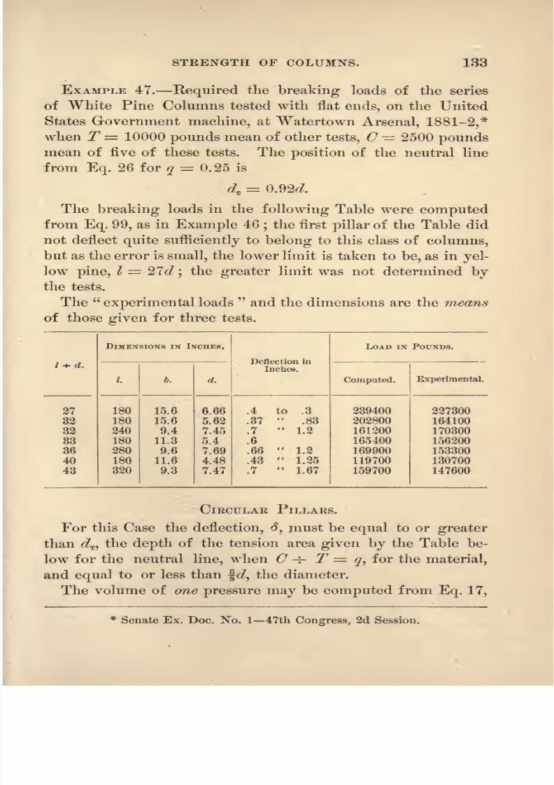
8/14/2019 A theoretical and practical treatise on the strength of beams and columns (1889)
http://slidepdf.com/reader/full/a-theoretical-and-practical-treatise-on-the-strength-of-beams-and-columns-1889 151/196
STRENGTH OF COLUMNS. 133
EXAMPLE 47. Required the breaking loads of the series
of White Pine Columns tested with flat ends, on the UnitedStates Government machine, at Watertown Arsenal, 1881-2,*
when T= 10000 pounds mean of other tests, C 2500 poundsmean of five of these tests. The position of the neutral line
from Eq. 26 for q= 0.25 is
de= 0.92^.
The breakingloads in the
following Table were computedfrom Eq. 99, as in Example 46
;the first pillar of the Table did
not deflect quite sufficiently to belong to this class of columns,
but as the error is small, the lower limit is taken to be, as in yel-
low pine, I = 276?;the greater limit was not determined by
the tests.
The experimental loads and the dimensions are the means
of those given for three tests.

8/14/2019 A theoretical and practical treatise on the strength of beams and columns (1889)
http://slidepdf.com/reader/full/a-theoretical-and-practical-treatise-on-the-strength-of-beams-and-columns-1889 152/196
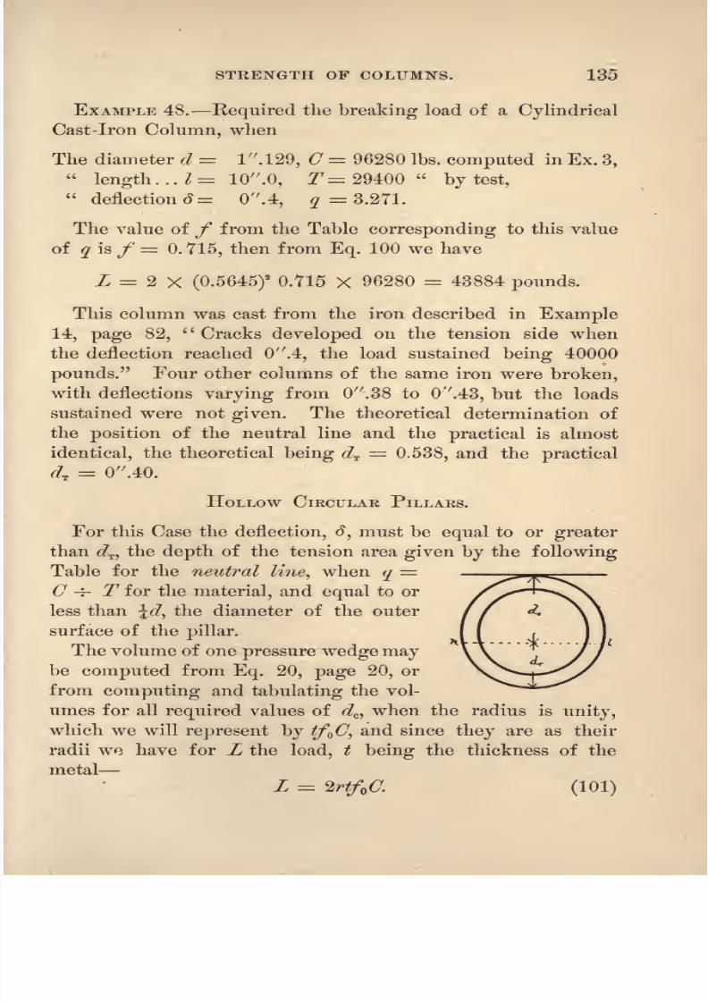
8/14/2019 A theoretical and practical treatise on the strength of beams and columns (1889)
http://slidepdf.com/reader/full/a-theoretical-and-practical-treatise-on-the-strength-of-beams-and-columns-1889 153/196
STRENGTH OF COLUMNS. 135
EXAMPLE 48. Required the breaking load of a Cylindrical
Cast-Iron Column, when
The diameter d 1 .129, C = 96280 Ibs. computed in Ex. 3,
length. .. == 10 .0, T= 29400
by test,
deflection 3= 0 .4, ?= 3.271.
The value of f from the Table corresponding to this value
of q is f 0. 715, then from Eq. 100 we have
L 2 X (0.5645)2
0.715 X 96280 = 43884 pounds.
This column was cast from the iron described in Example
14, page 82, Cracks developed on the tension side when
the deflection reached 0 .4, the load sustained being 40000
pounds. Four other columns of the same iron were broken,
with deflections varying from 0 .38 to Ov.43, but the loads
sustained were not given. The theoretical determination of
the position of the neutral line and the practical is almost
identical, the theoretical being dT=
0.538, and the practical
dT= 0 .40.
HOLLOW CIRCULAR PILLARS.
For this Case the deflection, #, must be equal to or greater
than 6?T ,the depth of the tension area given by the following
Table for the neutral line, when q=
C -f- T for the material, and equal to or
less than \d, the diameter of the outer
surface of the pillar.
The volume of one pressure wedge maybe computed from Eq. 20, page 20, or
from computing and tabulating the vol-
umes for all required values of d^ when the radius is unity,
which we will represent by tf O, and since they are as their
radii we have for L the load, t being the thickness of the
metal
L =2rtf C. (101)
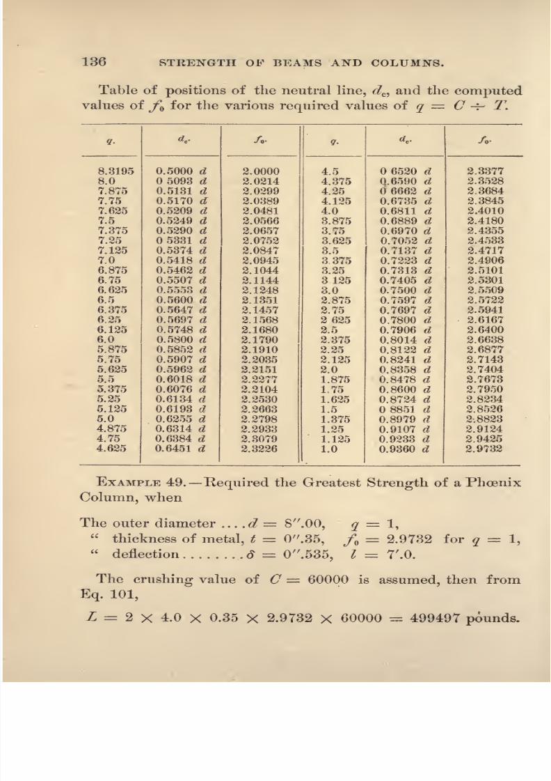
8/14/2019 A theoretical and practical treatise on the strength of beams and columns (1889)
http://slidepdf.com/reader/full/a-theoretical-and-practical-treatise-on-the-strength-of-beams-and-columns-1889 154/196

8/14/2019 A theoretical and practical treatise on the strength of beams and columns (1889)
http://slidepdf.com/reader/full/a-theoretical-and-practical-treatise-on-the-strength-of-beams-and-columns-1889 155/196
STRENGTH OF COLUMNS. 137
By the United States Government Watertown Arsenal
tests the greatest strength was 468000 pounds.*
117. Case V. PILLARS THAT CROSS-BREAK FROM COM-
PRESSION AND CANTILEVERAGE.
The shortest pillar of this class, for a given section and
material, is that length that just deflects sufficiently to allow the
resultant of the applied load to pass to the right of the fulcrum
f (Fig. 34). This for a given material varies with the section,
and the class includes all pillars of longer lengths. The
amount of direct pressure along the \mefn is equal to the sum
of the two equal pressure wedges described in Case IY. for
the given cross-section, and is the same for all deflections, but
to obtain the breaking load of the pillar this sum must be di-
minished by the tensile and compressive strain that arises from
the load's action as a cantilever.
C ' = the greatest intensity of the compressive strain arising
from bending action of the load.
RECTANGULAR PILLARS.
d \d = the lever-arm of the load, L.
Then the moment of the applied load will be, from Eq. 23,
p. 38,
r , _ L (W - d)
~~MT
Then we will have for the applied load, Z,
L = MCC-MC C',
* Ex. Doc. No. 23, House of Representatives, 46th Congress, 3d Session,
p. 278.

8/14/2019 A theoretical and practical treatise on the strength of beams and columns (1889)
http://slidepdf.com/reader/full/a-theoretical-and-practical-treatise-on-the-strength-of-beams-and-columns-1889 156/196
138 STRENGTH OF BEAMS AND COLUMNS.
from which, by substituting the above value of C'',we ob-
tainr _ M*CL - ---
d
When 3# becomes equal to or less than ^, the depth, the for-
mula becomes that for rectangular pillars
ofCase IV.,
the cantilever effect of the
load having disappeared.
As before stated, the formulas deduced
1 for the strength of columns that fail by
cross-breaking with cantileverage are iden-
tical in form with those given by Mr.
Lewis Gordon, but, unlike his, they give
exact values and show when the formula does not apply. This
uncertainty as to the length of pillars to which Gordon's for-
mulas did not apply has been the chief objection to their use
in practice.
Adapting Gordon's formula for the strength of rectangu-
lar pillars to our notation, we have
AC
From making A the full area of the column, the factor C
could never be the crushing strength of the material, but is
always something less than it in value. The second member
of the denominator makes the formula true for all lengths of
pillars,which experiment does not confirm, and is of the same
general form as our formula for the deflection given by Eq.
93.
~No successful effort has ever been made to so modify Gor-
don's formula that the computed and experimental strength

8/14/2019 A theoretical and practical treatise on the strength of beams and columns (1889)
http://slidepdf.com/reader/full/a-theoretical-and-practical-treatise-on-the-strength-of-beams-and-columns-1889 157/196
STRENGTH OF COLUMNS. 139
of wooden columns would be the same in value;and for
the reason thatin all
published results of experiments onwooden pillars, except for a few on yellow pine made at
the Watertown Arsenal, they all failed without cantilev-
erage of the applied load, and the deflection did not enter
as a factor to decrease the strength as contemplated by Gor-
don.
In the tests of white and yellow pine columns made at the
Watertown Arsenal, and described in Examples 46 and 47, the
strength was not decreased from cantileverage. For any
given rectangular section of thesepillars, the strength is the
same for all lengths from twenty-seven to forty-five times the
least diameter or least side of the rectangle, which includes
the lengths of all yellow arid w^hite pine pillars that are used
in structures.
EXAMPLE 50. Required the breaking load of a Rectangu-
lar Wrought-Iron Column, tested with two V\ pin ends,
when
The diameter ..... d 3 .0, C = 50000 pounds assumed.
breadth ...... I 3 .0, T 50000 pounds mean tests.
deflection ....= 1 .61, q = I.
The position of the neutral line from the Table, page 92, is
dc 0.78^; from Eq. 102 we have
Z = 8 X ^ X 5QOO= - = 197000 pounds.
3 X 1.61-3.0 1 -f 0.783
2.34
This example and those in the following Table are from the
series of tests described in Example 44, page 128, as given in
Senate Ex. Doc. No. 5 48th Congress, 1st Session, pp. 68
to 102.
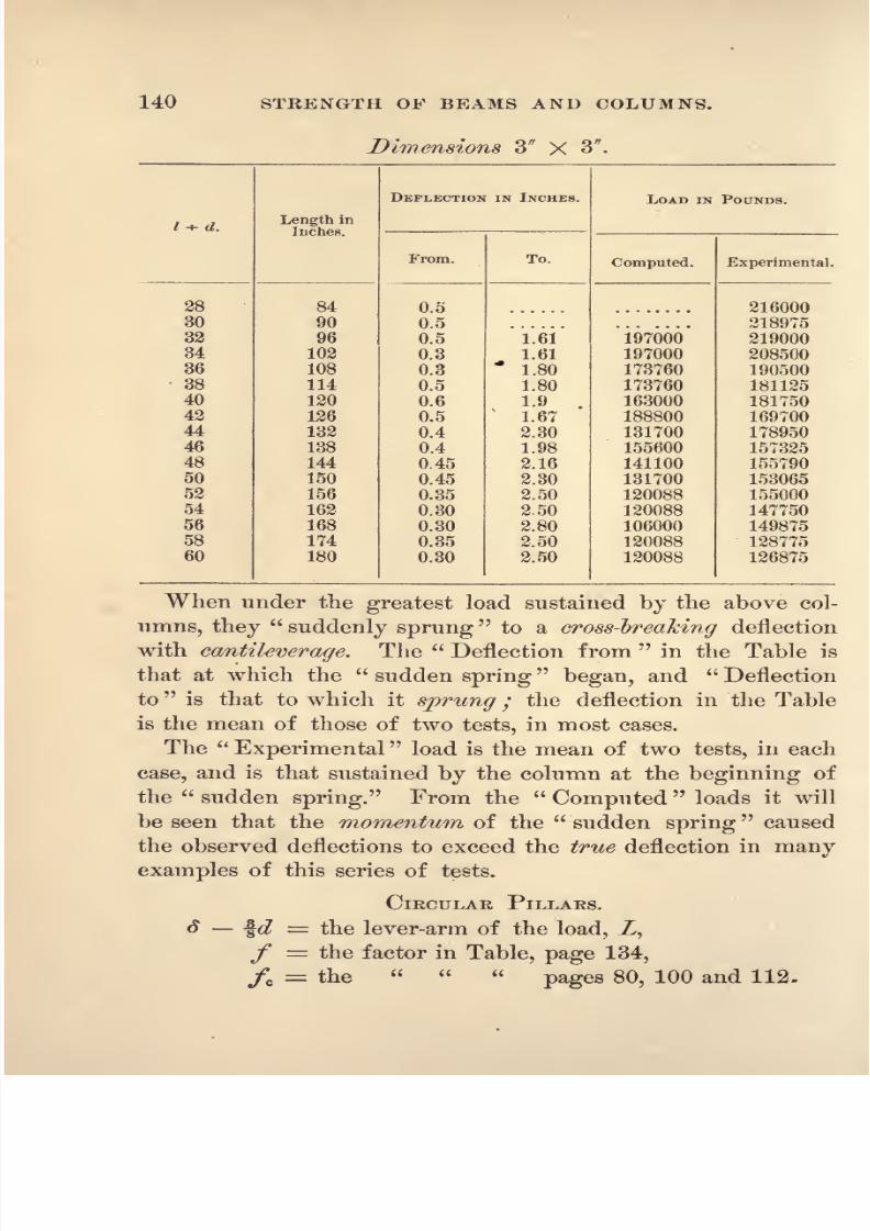
8/14/2019 A theoretical and practical treatise on the strength of beams and columns (1889)
http://slidepdf.com/reader/full/a-theoretical-and-practical-treatise-on-the-strength-of-beams-and-columns-1889 158/196
140 STRENGTH OF BEAMS AND COLUMNS.
Dimensions 3 X 3 .
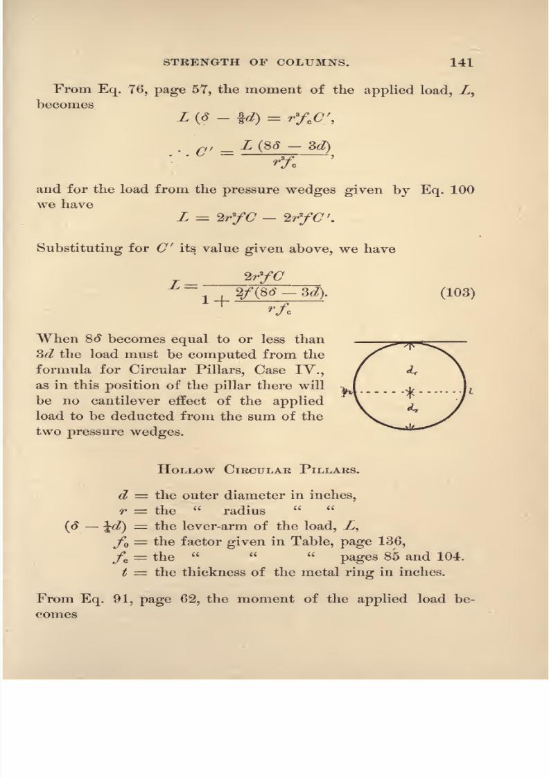
8/14/2019 A theoretical and practical treatise on the strength of beams and columns (1889)
http://slidepdf.com/reader/full/a-theoretical-and-practical-treatise-on-the-strength-of-beams-and-columns-1889 159/196
STRENGTH OF COLUMNS. 141
From Eq. 76, page 57, the moment of the applied load, Z,
becomesL (8
-\d)
=r>fe C ,
__ L (S3 3d)
and for the load from the pressure wedges given by Eq. 100
we have
L = WfC 2/y<7'.
Substituting for C' its value given above, we have
(103)
When 8# becomes equal to or less than
3d the load must be computed from the
formula for Circular Pillars, Case IY.,
as in this position of the pillar there will
be no cantilever effect of the applied
load to be deducted from the sum of the
two pressure wedges.
HOLLOW CIKCULAK PILLARS.
d = the outer diameter in inches,
r = the
radius
= the lever-arm of theload, Z,
fo= the factor given in Table, page 136,
/c= the
pages 85 and 104.
t = the thickness of the metal ring in inches.
From Eq. 91, page 62, the moment of the applied load be-
comes

8/14/2019 A theoretical and practical treatise on the strength of beams and columns (1889)
http://slidepdf.com/reader/full/a-theoretical-and-practical-treatise-on-the-strength-of-beams-and-columns-1889 160/196
142 STRENGTH OF BEAMS AND COLUMNS.
,- s^r
For the load, Z, we have
L =2rtf C - 2rtfQC
f
Substituting the value of C', we obtain
T ~
1 ,
(104)
2/tf
When is equal to or less than the outer diameter, d, the
strength of the column must be com-
puted from Eq. 101, Case IV., as there
will then be no cantilever effect to de-
duct.
EXAMPLE 51. Required the Breaking
Strength of a Phoenix Column tested
with flat ends;C = T = 60000 is the
assumed strength of the iron.
Outer diameter ____ d 8 .0, q = C -4- T 1,
Thickness of metal, t = 0 .35, /o = 2.9732 from Table, page 136, for q = l,
Deflection ......... d = 2 .47,/c = 2.6806
104,
q = l.
From Eq. 104 we have
2 X 4 X 0.35 X 2.9732 X 60000T _ 499497
,
2.9732 (4 X 2.47
2 X 4 X 2.6806
-8) 1+0.26
This example is taken from the series of experiments* de-
scribed in Example 49, page 136;the tested breaking load was
416000 pounds ;the length was 28 feet.
*Report of the United States Board appointed to test iron and steel, Ex.
Doc. No. 23, House of Representatives, 46th Congress, 2d Session, page
270.

8/14/2019 A theoretical and practical treatise on the strength of beams and columns (1889)
http://slidepdf.com/reader/full/a-theoretical-and-practical-treatise-on-the-strength-of-beams-and-columns-1889 161/196
STRENGTH OF COLUMNS. 143
ANGLE-IRON, Box, CHANNEL, EYE-BEAM AND TEE PILLARS.
In pillars of the above sections, the distance of the neutral
line from that side of the pillar that will most likely be its
concave side, when broken, must be computed by the rules
heretofore given for it in beams of the section of the pillar.
The sum of the two pressure wedges will then be the product
of the compressed area, A^ by the crushing strength of the
material.
The distance, g,of the centre of gravity of the applied
load wedge from the point k (Fig. 34), must be determined,
which is obtained by computing RF, the moment of the load
wedge with respect to the axis, &, in which F is the greatest
intensity of the load at &, it being zero at w, and It a factor
that depends for its value upon the section;for any given
dimensions it reduces to a numerical quantity without assign-
ing any value to F\ and dividing this moment, RF\ by the
volume of the load wedge, AF -r- 2, in which A is the area
of the section, we have
and
Then we haveT - AH AT'Ly -J-l-c^ J-J-c^
Substituting the above value of (7',we deduce
ACO~-
1 + A(* --<?). (105)
7?c is a factor of the moment of resistance that the section
of the pillar offers to the cantilever bending of the load;for
a given section it becomes a numerical quantity without assign-

8/14/2019 A theoretical and practical treatise on the strength of beams and columns (1889)
http://slidepdf.com/reader/full/a-theoretical-and-practical-treatise-on-the-strength-of-beams-and-columns-1889 162/196

8/14/2019 A theoretical and practical treatise on the strength of beams and columns (1889)
http://slidepdf.com/reader/full/a-theoretical-and-practical-treatise-on-the-strength-of-beams-and-columns-1889 163/196
CHAPTEE VIII.
COMBINED BEAMS AND COLUMNS.
118- General Statement. In roof-trusses, cranes,
derricks, platforms supported bj cantilevers, trussed beams and
other structures, there is used a class of pieces of material that,
from the manner in which they are loaded, do not belong ex-
clusively to either horizontal beams or columns, but partake of
the nature of both, in the manner in which they support the
load to whichthey
are subjected.
The theory of the transverse strength of these Combined
Beams and Columns gives the solution of the general problem
of the transverse strength of all beams, without regard to the
special angle that the axis of the beam makes with the line of
direction of the loading and supporting forces. Horizontal
beams acting under vertical loads and columns are only special
cases of thegeneral problem,
in which certainfactors,
that
cause the strength of the same piece of material to vary with
its angle of inclination to the horizon, disappear, from the
general rule for these cases, by becoming zero in value.
But on account of their great importance, we have, in the
preceding chapters, deduced separately the principles and rules
from which the strength of these special cases may be com-
puted.. Should one end of a horizontal beam, such as be (Fig. 44),
be fixed in a vertical wall, and a load be attached to its free
end, not suspended, as in the figure,none of this load will di-
rectly compress or rest upon the cross-section of the beam, ~be.
ISTow let the wall be revolved around the point F, to a horizon-
tal position, thus bringing the beam, ~be,to the vertical, then the

8/14/2019 A theoretical and practical treatise on the strength of beams and columns (1889)
http://slidepdf.com/reader/full/a-theoretical-and-practical-treatise-on-the-strength-of-beams-and-columns-1889 164/196
146 STRENGTH OF BEAMS AND COLUMNS.
entire load will rest
upon
or directly compress the cross-section
of the beam, now converted into a pillar ;the load has thus been
gradually converted from a non-compressing to a compressing
load with its full weight. The bending moment of the attached
load is greatest when the beam is in the horizontal position, and
it gradually diminishes as its lever-arm, ,<?,becomes less in value
with the revolution of the wall, and becomes zero in value
when the beamoccupies
the vertical
position.
On the other
hand, should the wall be revolved to the horizontal position
around the point P, the bending moment will gradually de-
crease and become zero, while the tensile strain will increase
from zero to that of the full weight of the load, when the
beam becomes vertical.
From the above illustration the origin of the special cases
of horizontal beams and columns is
apparent,and the reason
for the special rules for their strength. A similar illustration
could be deduced from a beam supported at both ends, by con-
ceiving it to occupy all positions from the horizontal to the
vertical.
In order to deduce the relation that exists between the
applied load and the resistance of the combined beam and
columnat
theinstant
of rupture,it is
assiimed,in the
analy-
sis,that they only deflect enough to admit of their cross-break-
ing as a column, without cantileverage of the applied load, as
in Class IV., Chapter VII. In very long beams, however, the
compression resulting from pressure applied to its ends will
act with the leverage explained in Case V., page 137, and the
strength must be computed from the formulas there given, but
the compression resulting from the transverse bending of theload will be the same in each case, and will compress the beam
without cantileverage.
119. Notation. In addition to the notation heretofore
used and defined in Art. 35, page 37, the following will be
used in this Chapter :

8/14/2019 A theoretical and practical treatise on the strength of beams and columns (1889)
http://slidepdf.com/reader/full/a-theoretical-and-practical-treatise-on-the-strength-of-beams-and-columns-1889 165/196
COMBINED BEAMS AND COLUMNS. 147
C = 6 + C the greatest intensity of the compressive strain
in pounds per square inch,
C' the greatest intensity of the compressive strain in pounds
per square inch, arising from the bending componentof the load,
<7 the greatest intensity of the compressive strain in pounds
per square inch, arising from the compressing compo-nent of the applied load,
ZB the bending component of the applied load in pounds,
Zc== the compressing component of the applied load in pounds,
I = the unsupported length of the beam in inches,
8 = the span, the horizontal distance between the supports
in inches,
h ~ the difference between the heights of the ends of the
beam in inches,
a = the angle that the beam makes with the horizon.
In many of the different methods of loading and supports
ing beams given in this Chapter, the greatest resulting com-
pressive strain at any section is the sum of two or more dis-
tinct pressures, which will be represented by the letter C, with
corresponding accents, such as C', C , C' , C,etc.
INCLINED BEAMS.
12O. General Conditions. The effect produced bya load when applied to this class of beams will manifest itself
in two distinctly different ways ;each separate effect must be
computed, and their sum will be the total effect produced -by
the load
uponthe beam. This is
accomplished by decompos-ing the applied load into two components, by the well-known
theorem of the parallelogram of forces. One component, ZB,
must be at right angles to the axis of the beam, and the other,
Zc , parallel with it
;the first component will bend the piece as
a learn, while the second will compress it as a column.
The parallelogram of forces for inclined beams is a rect-

8/14/2019 A theoretical and practical treatise on the strength of beams and columns (1889)
http://slidepdf.com/reader/full/a-theoretical-and-practical-treatise-on-the-strength-of-beams-and-columns-1889 166/196

8/14/2019 A theoretical and practical treatise on the strength of beams and columns (1889)
http://slidepdf.com/reader/full/a-theoretical-and-practical-treatise-on-the-strength-of-beams-and-columns-1889 167/196
COMBINED BEAMS AND COLUMNS. 149
and
L, = ~- (109)
The bending moment of the component, ZB,its lever-arm
being ,will be
/?
BendingMoment, ZB== -,-X I Ls. (110)
i
Having decomposed the applied load, Z, into two compo-
nents, one perpendicular and the other parallel to the inclined
beam, we can now ascertain the effect that will be produced bythe original load upon it, by a combination of the methods
used to compute the effect produced upon horizontal beams
and columns by vertical applied loads.
RECTANGULAR BEAMS.
The transverse strength of a rectangular beam loaded and
fixed as in this Case will now be deduced from the foregoing
formulas.
The bending moment from Eq. 110 must be made equal to
the moment of resistance from Eq. 23, page 38, in which
C= C'.
...Z*=^', (111)
3 Te
.>.' f?= U,C'. (112)ac
Thecompressing component,
Zc ,from Eq. 109, must be re-
sisted by an equal compression produced in the section at the
face of the wall, as given by Eq. 99, page 131, in which
C = C and L = ^,>
*=U,C . (113)
8/14/2019 A theoretical and practical treatise on the strength of beams and columns (1889)
http://slidepdf.com/reader/full/a-theoretical-and-practical-treatise-on-the-strength-of-beams-and-columns-1889 168/196
150 STRENGTH OF BEAMS AND COLUMNS.
Adding Eqs.112 and 113 we
have, by makingC '
+C
Cj the crushing strength of the material,
from which
r _
When the beam is horizontal, h and I = s, the formula
reduces under this hypothesis to that given in Eq. 27, page 38,
in which m 1. In a vertical beam, s = and I A, the
formula reduces to that given for the strength of rectangular
columns, Eq. 99.
To Design a Rectangular Beam.
Thelength
I andheight
h will be controlled
bythe
positionin which the beam is to be used. A convenient depth, d,
must then be assumed, and the value of dc computed from
Eq. 26, page 38;then from Eq. 114 we obtain
aL
~id?e->
from which the required breadth, J, of a beam that will
break with a given load, Z, will be obtained by giving to Cthe value of the crushing strength of the material of which
the beam is to be constructed.
Case II. WHEN THE LOAD is UNIFORMLY DISTRIBUTED
OVER THE UNSUPPORTED LENGTH OF THE BEAM.
The resultant of the applied load will pass through the
middle of the length of the beam and the triangle, eot (Fig.
44), will, as in Case I., give the relation between the load and
its two components ;hence
(118)
8/14/2019 A theoretical and practical treatise on the strength of beams and columns (1889)
http://slidepdf.com/reader/full/a-theoretical-and-practical-treatise-on-the-strength-of-beams-and-columns-1889 169/196
COMBINED BEAMS AND COLUMNS. 151
The bending moment of the component, ZB ,will be,
Bending Moment :=->< -, (H^)2 2
its lever-arm being I -=- 2.
RECTANGULAR BEAMS.
The transverse strength of a rectangular beam loaded and
fixed as in this Case may be obtained by the same process
heretofore used in Case L,
(120)
ToDesign
aRectangular
Beam.
Assume a depth, d, and compute dcfrom Eq. 26, page 38,
then from Eq. 120 we have
22. Inclined Beam, supported at one endand STAYED or held in position at the other with-
out vertical support. This class of Inclined Beams is
illustrated inFigs. 45, 46 and 47. Five different cases of
loading will be considered.
Case I. WHEN THE INCLINED BEAM is LOADED AT ITS
STAYED END.
The effect produced by the load, L, upon the beam, be (Fig.
45), is simply to compress it as a column, the load being held
in equilibrium by a pull along the tie ec, and a thrust along
the inclined beam.
In the right-angle triangle, toe, let et represent the load

8/14/2019 A theoretical and practical treatise on the strength of beams and columns (1889)
http://slidepdf.com/reader/full/a-theoretical-and-practical-treatise-on-the-strength-of-beams-and-columns-1889 170/196
152 STRENGTH OF BEAMS AND COLUMNS.
drawn to
any givenscale, then to gives the pull and oe the
thrust.
et te
ot =tan. a
, oe =s^n. a
and
LsThe pull = -7-5
The thrust Lc
= -v- ?
(122)
(123)
from which the compressing effect of the applied load, Z,
can be ascertained.
RECTANGULAR BEAMS.
The direct compression given by Eq. 123 must be made
equal to the resistance offered by the section of the beam as a
column, then from Eq. 99, page 131,
LI
T ~~ UA
.Z = ***(124)

8/14/2019 A theoretical and practical treatise on the strength of beams and columns (1889)
http://slidepdf.com/reader/full/a-theoretical-and-practical-treatise-on-the-strength-of-beams-and-columns-1889 171/196
COMBINED BEAMS AND COLUMNS.
Case II, WHEN THE INCLINED BEAM is LOADED AT ITS
MIDDLE.
Let be (Fig. 46) represent the beam loaded at its middle, t,
with the load, Z, then in the right-angle triangle, toe, et rep-
resents the load drawn to any scale, ot, perpendicular to the
beam, be, the lending component, ZB ,and ot parallel to be, the
directly compressing component, Zc.
LhI
'
(125)
(126)
The bending moment produced by the component, ZB ,is
identical with that produced by conceiving the beam to be
fixed
at its middle, t,
and loaded at the free end with
ZB -f- 2,
. .
Bending Moment, ZB =
'
T X ^ = -7-- (127)2ii 2i 4:
In order that the loading and supporting forces shall be in
equilibrium, one half of the bending component, ZB ,must be
supported at each end of the beam b and c. The half of ZB
at c cannot be directly supported at that point, but must be
8/14/2019 A theoretical and practical treatise on the strength of beams and columns (1889)
http://slidepdf.com/reader/full/a-theoretical-and-practical-treatise-on-the-strength-of-beams-and-columns-1889 172/196
154 STRENGTH OF BEAMS AND COLUMNS.
carried to the ground by some means. The method of stay-
ing the end of the beam, be, represented in the figure is that
used in roof-trusses;hence the load, ZB -j- 2 at c,
must be de-
composed into two components, one in the direction of each
beam or rafter;
if the angle, bek, is a right angle the entire
load, ZB -f- 2, compresses the rafter, ck, as apillar, thus reach-
ing the support, k.
In roof-trusses the inclined beams, he andck>, are usually
loaded in the same manner, and each beam will, therefore,
carry to c a component, ZB -7- 2, of its load for support, which
will be equivalent to the component, ZB -4- 2, compressing
each rafter to which it is applied, but much increased in
amount from the manner in which it is converted from a load
that is perpendicular to the beam into a compressing load
that isparallel to its axis.
In the two equal triangles, cmn, let cm in each represent the
load, LB -r- 2, en. the equal components that the rafters exchange
with each other, and mn the equal components that the
loads, ZB -f- 2, produce that strain the rafters to which they
are applied. When the angle, tick,is greater than 90 the
sum of the components (mn -f- en) will be greater than ZB -f- 2,
when ~bek 90, (mn -j- en)= ZB -r- 2, mn becoming zero.
When hcJc is less than 90 the component, mn, is a tensile
strain;the total compression (cm mn) will then be less than
z.-a.In roof-trusses the angle, ~bck,
is generally greater than 90,
and the total compression upon each rafterresulting from the
component of the load that it carries to c is (mn -[- en).
mn = me . tan. (90 2),
meen, =
cos. (90
21
LsAdding and substituting me = r, we have

8/14/2019 A theoretical and practical treatise on the strength of beams and columns (1889)
http://slidepdf.com/reader/full/a-theoretical-and-practical-treatise-on-the-strength-of-beams-and-columns-1889 173/196
COMBINED BEAMS AND COLUMNS. 155
.
(128)
The factor, c,in this equation, for convenience is
c = tan. (90 20) -| 5.
(129)
When the angle a = 45, tan. (90 2a) 0, 4 =*>
and the amount of compression will become = _ the2 21
angle, bck, being a right-angle.
The total compression produced by the single load, Z, at the
middle of each rafter will be the sum of the three distinct parts,
represented by Eqs. 126, 127 and 128.
RECTANGULAR BEAMS.
The amount of direct compression from Eqs. 126 and 128
must be equal to the resistance of the beam as a column, from
Eq. 99, page 131, in which C C' and C C'respectively.
.-.
^
= bdc C , (130)
and
^ = bde C' . (131)
The bending moment from Eq. 127 must be equal to the
moment of resistance of the section as a beam from Eq. 23,
page 38, in which C C .
.'. 2L=M&, (132)
= bdcC . (133)
Adding these separate components, as given by Eqs. 130,

8/14/2019 A theoretical and practical treatise on the strength of beams and columns (1889)
http://slidepdf.com/reader/full/a-theoretical-and-practical-treatise-on-the-strength-of-beams-and-columns-1889 174/196
156 STRENGTH OF BEAMS AND COLUMNS.
131 and 133, and making C'+ C + C' =C, the greatest
compressive strength of the material, we have
. L _
from which the required breaking load may be computed.
Case III, WHEN THE LOAD is UNIFORMLY DISTRIBUTED
OVER THE LENGTH OF THE INCLINED BEAM.
The bending moment and the component Zcwill be identi-
cal with those produced by conceiving one half of the total
load, Z, to be concentrated at its middle section, t (Fig. 46) ;
then, from Eqs. 125, 126 and 127, Case II., by makingL = L -r- 2, we have
^ = ~, (137)av
Bending Moment, LK- (138)
The bending moment is produced by a component of the
load, Z, that is perpendicular to the length of the beam, and
uniformly distributed over its length, bo. In order that equili-
brium shall exist, one half of this uniformly distributed com-
Lsponent, __ must be supported at each end of the beam, and as
L
it cannot be directly supported at the stayed end, c,it must be
carried to the supports b and &, as described in Case II., Eq.
128.
The method of analysis of the strains in a simple roof-truss,
given in this and the preceding Case, differs from that usually
8/14/2019 A theoretical and practical treatise on the strength of beams and columns (1889)
http://slidepdf.com/reader/full/a-theoretical-and-practical-treatise-on-the-strength-of-beams-and-columns-1889 175/196
COMBINED BEAMS AND COLUMNS. 157
pursued by writers. One half of the load on each rafter is
usually considered to be supported by b and k, and the other
half of each rafter load to be supported at c9 by reacting against
each other. The transverse strength is then computed as if the
rafter were a horizontal beam, which is equivalent to saying,
that for a given material, section and span of roof, as in Fig.
46, the transverse strength would be the same for the infinite
number of roof-trusses that could be constructed between these
points of support by varying the pitch or angle that the rafter
makes with the horizon, which, of course, is not the case.
RECTANGULAR BEAMS.
From Eqs. J28, 137 and 138, we obtain, by api
to that used in Case III.,
(139)
EXAMPLE 52. Required the uniformly distributed breaking
load of a White Pine Rafter, as in Fig. 46, when
The span ...... s = 15'. 0, C = 5000 pounds mean of tests,
length..... I 16'. 8, T = 10000
rise .......h= T. 5, g= 0.5,
depth .....d= 9 .0, de
= OMSd, from Table, page 108,
breadth. . .b = 5 .0, a =- 26.34'.
From Eq. 129, c = 2, then, from Eq. 140,
L = X 201.6 X (7.81 2)a
X 5000
3X180X201.6+(4X90+2X2X38).S6SX9
This Example is taken from Trautwine's Engineer's
Pocket-Book, and was designed to sustain an uniformly dis-
tributed load of 8000 pounds, with a factor of safety of three.
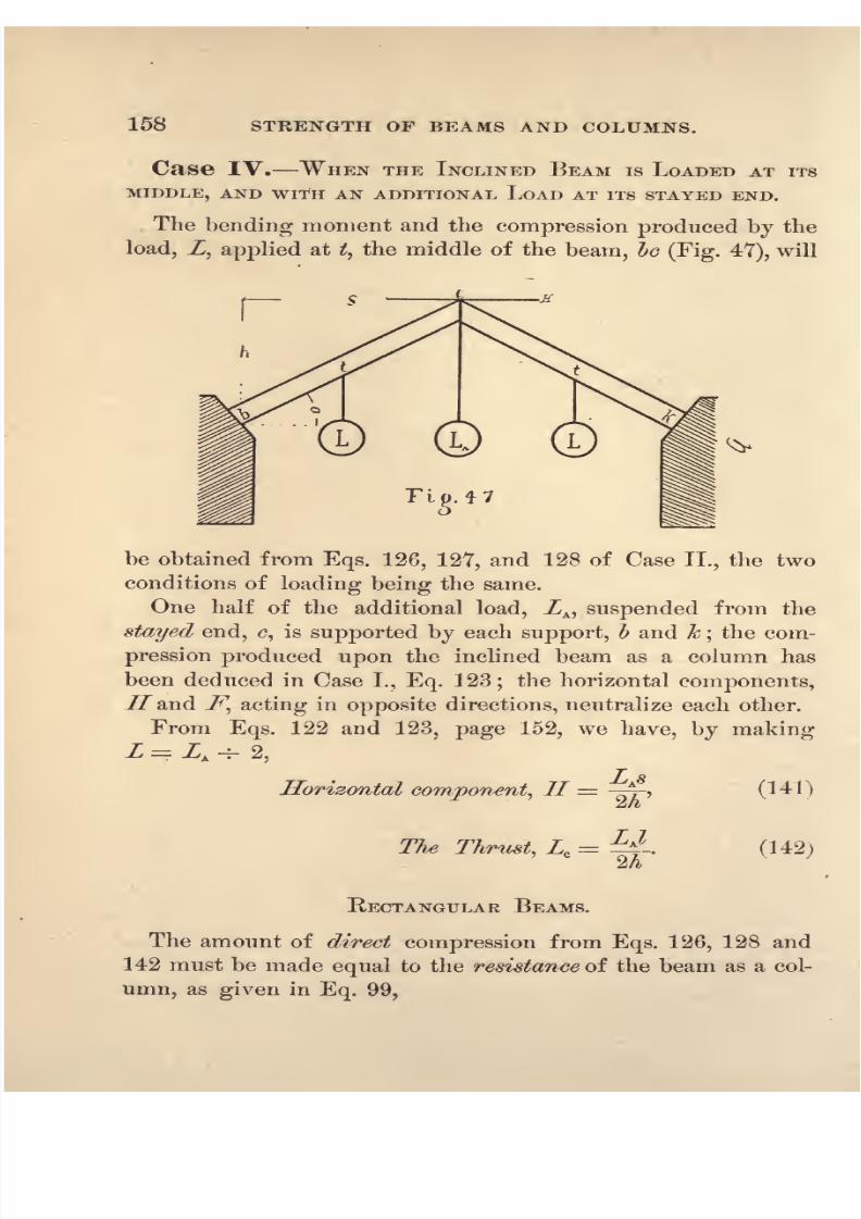
8/14/2019 A theoretical and practical treatise on the strength of beams and columns (1889)
http://slidepdf.com/reader/full/a-theoretical-and-practical-treatise-on-the-strength-of-beams-and-columns-1889 176/196

8/14/2019 A theoretical and practical treatise on the strength of beams and columns (1889)
http://slidepdf.com/reader/full/a-theoretical-and-practical-treatise-on-the-strength-of-beams-and-columns-1889 177/196
COMBINED BEAMS AND COLUMNS. 159
** = M C'9
(143)
* = 1>dG C '9 (144)2t
LJ = ldcC . (145)Ail/
The lendingmoment from
Eq.127 must be
equalto the
moment of resistance of the section of a beam from Eq. 23,
page 38, in which C= C ,
(147)
Adding Eqs. 143, 144, 145 and 147, and making
C' + 6r// + C' + C =
C, the crushing strength of the ma-
terial, we have
r__
from which the centre breaking load of the beam may be com-
puted, in addition to that of ZA suspended directly from its
stayed end.
Case V. WHEN THE LOAD is UNIFORMLY DISTRIBUTED
OVER THE LENGTH OF THE INCLINED BEAM, AND AN ADDITIONAL
LOAD, _Z/A ,APPLIED TO ITS STAYED END.
This Case is Cases III. and IT. combined, therefore Eqs.
128, 137, 138 and 142 will be the formulas required for
computing the transverse strength of the beam.

8/14/2019 A theoretical and practical treatise on the strength of beams and columns (1889)
http://slidepdf.com/reader/full/a-theoretical-and-practical-treatise-on-the-strength-of-beams-and-columns-1889 178/196
160 STEENGTH OF BEAMS AND COLUMNS.
RECTANGULAR BEAMS.
The direct compression from Eqs. 128, 137 and 142 must
be equal to the resistance of the beam, as a column, from Eq.
99, page 131.
== M C', (150)
(151)JIC
Lcs2 = UJ3 . (152)
The bending moment from Eq. 138 must be equal to the
moment of resistance of the section as a beam from Eq. 23,
page 38, in which C C ,
= ^','
(^3)
~ == UJO . (154)
Adding Eqs. 150, 151 and 152, we obtain by making
C' + C + C' + C C.
Inclined Beam Supported vertically at
both ends and loaded at its middle.
Let Fig. 49 represent the beam, supports and the load, Z.
In the triangle, toe, let eo, to any scale represent the load, Z,
then the component, ot, at right angles to the beam, will bend
it and et parallel to the beam will compress it as a column.

8/14/2019 A theoretical and practical treatise on the strength of beams and columns (1889)
http://slidepdf.com/reader/full/a-theoretical-and-practical-treatise-on-the-strength-of-beams-and-columns-1889 179/196
COMBINED BEAMS AND COLUMNS. 161
and
Fig. 49.
ot = eo cos. a and ot eo sin. a,
Ls^B
-=-j,
T LhA= T-
(157)
(158)
One half of the bending component, ZB ,will be supported by
the walls under each end of the beam;the bending moment
will therefore be
Ls I LsSending Moment, ZB
= y X3-=
(1^9)Li 2i 4:
Having decomposed the load into two components, one
perpendicular and the other parallelto the axis of the inclined
beam, we can compute its effect upon a beam of any section
and material.
LOAD SUSTAINED BY THE SUPPORTS.
Each of thewalls, supporting
the ends of the inclinedbeam,
must resist a thrust of one half of the bending component, Lwwhich tends to overturn them. Decomposing this thrust at
each support into a vertical and horizontal component, the
first will be the proportion of the centre load, Z, that is sus-
tained by the higher support. The lower support also sus-

8/14/2019 A theoretical and practical treatise on the strength of beams and columns (1889)
http://slidepdf.com/reader/full/a-theoretical-and-practical-treatise-on-the-strength-of-beams-and-columns-1889 180/196
162 STRENGTH OF BEAMS AND COLUMNS.
tains an equal vertical component, and in addition a vertical
component
of the
compressing component
of the
appliedload, Z.
The horizontal thrust against the higher support will be the
horizontal component of one half of ZB ;that at the lower
support will be the sum of the two horizontal components
arising from decomposing Zc and ZB -7- 2 at the lower support.
From the above we obtain,
LsVertical load on higher support= =
jcos. a,
L fs \
Vertical load on lower support=
-j( cos. a -{- h sin. a\.
When the beam becomes horizontal the angle a = o, s = I,
cos. a = 1 and the sin. a = o; substituting the values in
the above formulas, we find that each wall supports one half
of the load, Z, as in Case III., page 4.
RECTANGULAR BEAMS.
The direct compression from Eq. 158 must be equal to the
resistance of the beam as a column from Eq. 99, page 131.
^ = MC C'. (160)L
The lending moment, from Eq. 159, must be equal to the
moment of resistance of the beam, from Eq. 23, page 38.
Ls =M^4:
O
.
-
.
g*-
ld.C*. (162)
Adding Eqs. 160 and 161 we have, by making C' + C C,
the compressive strength of the material.

8/14/2019 A theoretical and practical treatise on the strength of beams and columns (1889)
http://slidepdf.com/reader/full/a-theoretical-and-practical-treatise-on-the-strength-of-beams-and-columns-1889 181/196
COMBINED BEAMS AND COLUMNS. 163
(163)
(164)
from which the centre breaking load of any rectangular
inclined beam supported at both ends may be computed.
. Inclined Beams supported at both ends
and the load uniformly distributed over its
length.
The bending moment and compression are identical with that
produced by conceiving the beam to be fixed at its middle
and loaded on its free ends with an uniformly distributed load,
L -i- 2, as in Case II., page 150, L being equal to Z -=- 2
Ls .
Lh-
The bending moment will be,
Sending Moment, ZB=
j X j-=
-Q-21 4: 8
From these components the effect of the uniformly distrib-
uted load on an inclined beam of any section and material maybe computed as in Art. 123.
LOAD SUSTAINED BY THE SUPPORT.
For an uniformly distributed load, Z, the amount of vertical
pressure that will be sustained by each wall will be obtained
fromthe formulas
before deducedfor a concentrated
load, Z,at the middle of the span, the proportion of the total load
sustained by the walls being the same in each case of loading.
The method usually given by writers for determining the
load supported by each wall, and the bending moment of the
load applied to an inclined beam, is to consider one half of the

8/14/2019 A theoretical and practical treatise on the strength of beams and columns (1889)
http://slidepdf.com/reader/full/a-theoretical-and-practical-treatise-on-the-strength-of-beams-and-columns-1889 182/196
164 STRENGTH OF BEAMS AND COLUMNS.
total load to be sustained by each wall and the bending mo-
ment to be the same as if the
beamwere
horizontal,the
spanused in the computation being the horizontal distance, $,
between the supports. This method of analysis is manifestly
incorrect, as it would require that an inclined beam of a given
scantling should have a transverse strength that would neither
be varied by its length nor the angle that it makes with the
horizon, provided its horizontal span remained the same. Or
that an inclined beam that is infinitely long, and a horizontalbeam whose span is the distance between the supports of the
inclined beam, will have the same transverse strength, pro-
vided the cross-section and material are the same in each beam.
RECTANGULAR BEAMS.
(165)
8 3 8rfc
Adding Eqs. 165 and 166, we have, by making C' + C = C,
TRUSSED BEAMS.
125. General Conditions. In trussed beams and
roof-trusses, beams are frequently subjected to both trans-
verse and longitudinal strains either of compression or tension,
thus acting in the double capacity of a horizontal beam and a
vertical column.
RECTANGULAR BEAMS.
Let Fig. 48 represent such a rectangular beam loaded
transversely with a total load, Z, and longitudinally with
either a compressive or tensile load,. Zc.

8/14/2019 A theoretical and practical treatise on the strength of beams and columns (1889)
http://slidepdf.com/reader/full/a-theoretical-and-practical-treatise-on-the-strength-of-beams-and-columns-1889 183/196
COMBINED BEAMS AND COLUMNS. 165
From Eq. 27, page 38, in which C C , we have
3s(168)
(169)
And from Eq. 99, page 131, we have
Zc= ld,C . (170)
Adding Eqs. 169 and 170, we. have, by making C'-\-C C,
Sg-*A==**a (ni)mdz
From which either Z, Zc,
or & may be computed when the
other two are known.
'H-tf-X^(m)
3
(173)
(174)
HOLLOW CIRCULAR BEAMS.
The relation between the transverse load, Z, and the result-
ing moment of resistance of the beam is given by Eq. 91,
page 62, in which C C f
.
8/14/2019 A theoretical and practical treatise on the strength of beams and columns (1889)
http://slidepdf.com/reader/full/a-theoretical-and-practical-treatise-on-the-strength-of-beams-and-columns-1889 184/196
166 STRENGTH OF BEAMS AND COLUMNS.
fc= the factor from the
Table, pages
81 and 104,
/ = the page 136.
L = wftf.0' = , (175)
The compression from the longitudinal strain, Zc, must be
equal to the resistance of the beam as a column from Eq. 101,
page 135, in which O = C .
Zc=
totf.C . (177)
Adding Eqs. 176 and 177 we have
Zc= %rtf& (178)
-
mrfc
c c
~2/r
The compressing load, Zc ,in the foregoing formulas, in
practice, generallyresults from the transverse
load, Z,its
effect being transmitted to the ends of the beam by a vertical
post placed under the centre of the beam and connected with
the ends by inclined truss-rods. For a single load, Z, at the
middle it is usually the practice to consider one half of it as
producing a tensile strain on each of the inclined truss-rods;
this is only strictly correct when the beam is cut into two
pieces at its centre. When the beam is continuous it can onlystrain the vertical post after it begins to deflect
;therefore the
load that would have caused the untrussed beam to deflect
from the horizontal position could bring no strain upon the
post.

8/14/2019 A theoretical and practical treatise on the strength of beams and columns (1889)
http://slidepdf.com/reader/full/a-theoretical-and-practical-treatise-on-the-strength-of-beams-and-columns-1889 185/196
INDEX.
PAGE
Beams. See Transverse Strength, Moment of Resistance and Neutral
Line.
Beams, Cast-Iron, . . 64
Wrought-Iron, 87
Steel, 87
Timber, 106
Horizontal, .......... 3
Inclined . 148
Trussed, 164
Elastic Limit 34and Columns, Combined, . . . .
'
. . . 145
Bending Moments, 3
General Formula, . . .... 6 Moment and Moment of Resistance, 22
Coefficients of Strength, 33
Columns, Box Section, 163
Classed, . . .123
Deflection of, . . 121
Experiments, 122
End Connections, 124
Failure of,without Deflection, . . . . . 125
with
127
without Cantileverage, 130
with
... . . 137
General Conditions of Failure, 114
Gordon's Formula, 138
Pin End,118
Resistance of, 119
Rectangular Sections, 128, 131, 137
Circular Sections, 129, 133, 140
Hollow Circular Sections, . . . . . 130, 135, 141
Angle-Iron, Eye-Beam, Channel, etc., .... 143
Combined Beams and Columns, 145

8/14/2019 A theoretical and practical treatise on the strength of beams and columns (1889)
http://slidepdf.com/reader/full/a-theoretical-and-practical-treatise-on-the-strength-of-beams-and-columns-1889 186/196
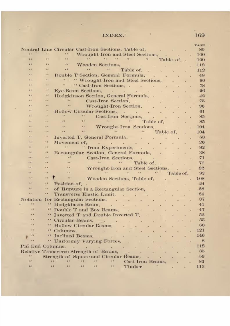
8/14/2019 A theoretical and practical treatise on the strength of beams and columns (1889)
http://slidepdf.com/reader/full/a-theoretical-and-practical-treatise-on-the-strength-of-beams-and-columns-1889 187/196
INDEX.
PAGE
Neutral Line Circular Cast-Iron Sections, Table of, ... 80
Wrought-Iron and Steel Sections,. . .
100
Table of, . 100
Wooden Sections, 112
Table of, .... 112
Double T Section, General Formula, .... 48
Wrought-Iron and Steel Sections, . . 96 Cast-Iron Sections, 78
Eye-Beam Sections, 96
Hodgkinson Section, General Formula, .... 42
Cast-iron Section, 75
Wrought-Iron Section, .... 96
Hollow Circular Sections, ...... 61
Cast-iron Sections, .... 85
Table of, . . 85
Wrought-Iron Sections, . . . 104
Table of, . 104
Inverted T, General Formula, ..... 53
Movement of,
........26
'from Experiments, ..... 82
Rectangular Section, General Formula, ... 38
Cast-Iron Sections, ..... 71
Table of, ... 71
Wrought-Iron and Steel Sections, . . 92
Table of, 92
Wooden Sections, Table of, ... 108
Position of, ......... 24
of Rupture in a Rectangular Section,
....28
Transverse Elastic Limit, . . . . . . 24
Notation for Rectangular Sections, ....... 37
Hodgkinson Beam, 41
' '
Double T and Box Beams, 47
Inverted T and Double Inverted T, . 52
Circular Beams, .55
Hollow Circular Beams, ...... 60
Columns 121
I Inclined Beams, ........
146
Uniformly Varying Forces, ...... 8
Pin End Columns, 118
Relative Transverse Strength of Beams, 35
Strength of Square and Circular Beams, .... 59
Cast-Iron Beams, . . 83
Timber
113

8/14/2019 A theoretical and practical treatise on the strength of beams and columns (1889)
http://slidepdf.com/reader/full/a-theoretical-and-practical-treatise-on-the-strength-of-beams-and-columns-1889 188/196
170 I1STDEX.
PAGE
Relative Value of the Crushing and Tensile Strength, ... 28
Resultant Defined,
.2 Uniformly Varying Forces, . . . . . 8, 16, 19
Strain,1
Stress,1
Tensile Strength, To Compute, 39, 58
of Cast-Iron, 64
To Compute, .... 6?
Wrought-Iron and Steel, . .... 87
To Compute 90
Timber, 106
To Compute, 106
Transverse Strength, General Conditions, 21
Box Beams, General Formulas, .... 48
Cast Iron Beams, 78
Wrought-Iron and Steel Beams, . . 96
Cast-Iron Beams, ...... 65
Circular Beams, General Formula, . . .56Cast-Iron Beams,
....81
Wrought-Iron and Steel Beams, . . 101
Wooden Beams, .... 112
Double T Beam, General Formula, ... 48
Wrought-Iron and Steel Beams, . 96
Cast- Iron Beams, . . . .78
Eye-Beams, Wrought Iron and Steel, . . 96
Hodgkinson Beam, General Formula, . . 44
Cast-Iron Beam 75
Wrought-Iron and Steel Beams,
.
96Hollow Circular Beams, General Formula, . 61
Cast-Iron Beams, ... 86
Wrought Iron and Steel Beams, 104
Inverted T, General Formula, . . . 5$
Rectangular Beams, General Formula, .
'
. 38
Cast-Iron Beams, .... 71
Wrought-Iron and Steel Beams, 92
Wooden Beams, . . . . 108
Steel Beams 92
AVrought-Iron Beams, 91
Timber Beams, 106
Trussed Beams,'
164
Working Load, 34

8/14/2019 A theoretical and practical treatise on the strength of beams and columns (1889)
http://slidepdf.com/reader/full/a-theoretical-and-practical-treatise-on-the-strength-of-beams-and-columns-1889 189/196

8/14/2019 A theoretical and practical treatise on the strength of beams and columns (1889)
http://slidepdf.com/reader/full/a-theoretical-and-practical-treatise-on-the-strength-of-beams-and-columns-1889 190/196

8/14/2019 A theoretical and practical treatise on the strength of beams and columns (1889)
http://slidepdf.com/reader/full/a-theoretical-and-practical-treatise-on-the-strength-of-beams-and-columns-1889 191/196
8/14/2019 A theoretical and practical treatise on the strength of beams and columns (1889)
http://slidepdf.com/reader/full/a-theoretical-and-practical-treatise-on-the-strength-of-beams-and-columns-1889 192/196

8/14/2019 A theoretical and practical treatise on the strength of beams and columns (1889)
http://slidepdf.com/reader/full/a-theoretical-and-practical-treatise-on-the-strength-of-beams-and-columns-1889 193/196

8/14/2019 A theoretical and practical treatise on the strength of beams and columns (1889)
http://slidepdf.com/reader/full/a-theoretical-and-practical-treatise-on-the-strength-of-beams-and-columns-1889 194/196
UNIVERSITY OF CALIFORNIA LIBRARYBERKELEY
Return to desk from which borrowed.
This book is DUE on the last date stamped below.
16lun'51CD
REC'D LD
)EC23'63-12Aifl
21-100m-9,'47(A5702sl6)476
8/14/2019 A theoretical and practical treatise on the strength of beams and columns (1889)
http://slidepdf.com/reader/full/a-theoretical-and-practical-treatise-on-the-strength-of-beams-and-columns-1889 195/196
V~<-
r

8/14/2019 A theoretical and practical treatise on the strength of beams and columns (1889)
http://slidepdf.com/reader/full/a-theoretical-and-practical-treatise-on-the-strength-of-beams-and-columns-1889 196/196