A Technical Discussion and Report on Adjustable Hosel...
10
A Technical Discussion and Report on Adjustable Hosel/Adjustable Sole Piece Drivers in the Modern Golf Equipment Industry By Tom Wishon ©Tom Wishon Golf Technology 1. Driver Head Position for Correct Loft, Lie and Face Angle Measurement During my entire career in clubhead design the most widely used machine for clubhead specifications measurement is the device shown in the image below: More commonly known in the golf equipment industry as “the Green Machine”, this device has been used by virtually every club- head production factory and golf equipment company to measure clubhead loft, lie, face angle and face progression since the early 1980s. Manufactured by Tecnorama Ltd of Kaohsiung, Taiwan, the Green Machine is considered the industry standard for clubhead specifications measurement. The Green Machine is a manual measurement machine. The opera- tor must learn the correct way to manually position each clubhead consistently in the machine to obtain accurate, repeatable measure- ments. Substantial training is required is required to teach a person how to properly position all types of different clubheads before the measurements can be relied upon as being accurate. While the manual operation of the machine can allow for a slight variation in the measurement of a clubhead’s specifications, indi- viduals with a depth of training and experience are able to become very consistent in the positioning of clubheads in the machine so that loft, lie and face angle measurements can be recorded within a tolerance of +/- 1/8° or less. Proper positioning of the driver head for accurate static specs This report originated because of claims being made on behalf of the modern adjustable hosel drivers that these adjustable devices allow the loft, lie and face angle to be customized for golfers. In 1995, I de- signed the first commercially available adjustable hosel device to allow a metal wood to be altered for lie and face angle. From my work to create this device, as well as from my experience in having made wooden woods early in my career, I believe that it is simply not possible to change the loft through a hosel device which operates on the principle of changing the angle of the shaft into the clubhead. Based on my experience, I find it difficult to believe the claims for specification adjustment being made on behalf of these modern adjustable hosel devices. Therefore, this report came about because I wanted to learn for myself if the modern versions of adjust- able hosel devices really could achieve the loft, lie and face angle specifications that the companies offering drivers say they can do. A technical report about the modern versions of adjustable hosel drivers has to begin with a discussion of three very important, related issues. • The manner in which a driver head is positioned in a clubhead specifications measurement machine for the correct static specifications measurement of loft, lie and face angle. • The importance of the static measurements of driver loft, lie and face angle to the goal of achiev- ing the optimum shot result for each individual golfer. • The manner in which golfers address the ball and manage the position of the drive head before hit- ting a shot. Note: the following report on modern adjustable drivers contains both a discussion of the methods of driver head specification measurement and typical driver head use as well as actual loft, lie and face angle measurements of a number of the golf industry’s adjustable driver models. If you are not interested in the technical discussion and only wish to view the specification measurements of the drivers measured in this study, you may [CLICK HERE] to go directly to the measurements
-
Upload
phungxuyen -
Category
Documents
-
view
212 -
download
0
Transcript of A Technical Discussion and Report on Adjustable Hosel...

A Technical Discussion and Report on Adjustable Hosel/Adjustable Sole Piece Drivers in the Modern Golf Equipment Industry
By Tom Wishon©Tom Wishon Golf Technology
1. Driver Head Position for Correct Loft, Lie and Face Angle Measurement
During my entire career in clubhead design the most widely used machine for clubhead specifications measurement is the device shown in the image below:
More commonly known in the golf equipment industry as “the Green Machine”, this device has been used by virtually every club-head production factory and golf equipment company to measure clubhead loft, lie, face angle and face progression since the early 1980s. Manufactured by Tecnorama Ltd of Kaohsiung, Taiwan, the Green Machine is considered the industry standard for clubhead specifications measurement.
The Green Machine is a manual measurement machine. The opera-tor must learn the correct way to manually position each clubhead consistently in the machine to obtain accurate, repeatable measure-ments. Substantial training is required is required to teach a person how to properly position all types of different clubheads before the measurements can be relied upon as being accurate.
While the manual operation of the machine can allow for a slight variation in the measurement of a clubhead’s specifications, indi-viduals with a depth of training and experience are able to become very consistent in the positioning of clubheads in the machine so that loft, lie and face angle measurements can be recorded within a tolerance of +/- 1/8° or less.
Proper positioning of the driver head for accurate static specs
This report originated because of claims being made on behalf of the modern adjustable hosel drivers that these adjustable devices allow the loft, lie and face angle to be customized for golfers. In 1995, I de-signed the first commercially available adjustable hosel device to allow a metal wood to be altered for lie and face angle. From my work to create this device, as well as from my experience in having made wooden woods early in my career, I believe that it is simply not possible to change the loft through a hosel device which operates on the principle of changing the angle of the shaft into the clubhead.
Based on my experience, I find it difficult to believe the claims for specification adjustment being made on behalf of these modern adjustable hosel devices. Therefore, this report came about because I wanted to learn for myself if the modern versions of adjust-able hosel devices really could achieve the loft, lie and face angle specifications that the companies offering drivers say they can do.
A technical report about the modern versions of adjustable hosel drivers has to begin with a discussion of three very important, related issues.
• The manner in which a driver head is positioned in a clubhead specifications measurement machine for the correct static specifications measurement of loft, lie and face angle.
• The importance of the static measurements of driver loft, lie and face angle to the goal of achiev-ing the optimum shot result for each individual golfer.
• The manner in which golfers address the ball and manage the position of the drive head before hit-ting a shot.
Note: the following report on modern adjustable drivers contains both a discussion of the methods of driver head specification measurement and typical driver head use as well as actual loft, lie and face angle measurements of a number of the golf industry’s adjustable driver models. If you are not interested in the technical discussion and only wish to view the specification measurements of the drivers measured in this study, you may [CLICK HERE] to go directly to the measurements

measurement begins with placing the head in its correct lie angle position. A number of methods for achieving the driver head’s cor-rect lie position have been developed over the years:
• If the face scorelines have been tooled or engraved to be paral-lel to the tangent to the apex of the toe to heel sole radius, and if the center of the face is vertically in line with the apex of the toe to heel sole radius, the head can be positioned so the bot-tom scorelines on the face are parallel to the base of the specs measurement machine.
• The head may be positioned so the apex of the toe to heel sole radius touches the base of the specs measurement machine. Upon gently sliding two business cards on the base of the ma-chine toward the center from the toe and heel sides, when the cards both stop the same distance away from the center point of the sole, the proper lie position is achieved. This is the method of choice when scorelines are not parallel to the apex of the toe to heel sole radius, or when the toe to heel radius is not uniform.
• The head may be positioned to touch the base of the specs measurement machine in the center of the sole vertically in line with the center of the face, then the head is tilted in the ma-chine so the distance from the base of the machine to the toe and heel side ends of the sole are the same distance up from the base of the machine. This method is not recommended if the toe to heel radius is not uniform.
Once the driver head is in the proper lie angle position, the head then has to be positioned for proper face angle and loft measure-ment while retaining the correct lie position. Prior to the mid 1990s this was easy to do because virtually every driver head was made so the plane of the sole along the ground line from face to back was completely flat. With a flat sole plane from face to back, all that is required for proper face angle positioning is to first position the head in the proper lie angle position, then press down on the top of the head to make the head to sit flat on its sole.
Driver heads today are often designed with a certain amount of sole radius from face to back or complex sole features which make finding the proper position for face angle measurement more of a challenge. For such heads, the operator has to determine the point on the sole from face to back that is the driver head’s predominant position of rest when the head is placed on a close mown or firm and level surface in its correct lie position.
Once this point or surface area of the sole from face to back is found the operator can mark the center of the predominant face to back sole rest position and duplicate that touch point when the head is positioned in the specs measurement machine.
Never since the invention of the clubhead specifications measure-ment machine has the face angle position deemed to be achieved when the driver head rests on any other point of the sole than its natural sole resting position on the predominant flat position of the sole. I will admit due to the variety of different driver sole shapes, it has become a challenge to know for sure what the correct face angle and loft position of driver heads is to be. Again, people with a lot of training and experience are able to determine this position
on a driver head with repeatable consistency.
Once the driver head is in its proper lie and face angle position in the specs measurement machine, the loft, the lie angle, the face angle and the face progression of the head can be measured.
2. The importance of the static measurements of driver loft, lie and face angle to the determination of the opti-mum shot results for each individual golfer.
The entire history of driver fitting has always been based on choos-ing the driver head to have specific static loft and face angle speci-fications that when subjected to the golfer’s swing characteristics will result in a particular shot result for each golfer. (Chiefly it is the golfer’s swing path, hand position, and angle of attack that dictate how the static clubhead specifications will translate into the shot result) The clubhead’s static specs, when subjected to the swing characteristics of the golfer, dictates a significant part of what the shot result will be. It is a pure “CAUSE AND EFFECT” situation.
Static Clubhead Specifications + Golfer Swing Characteristics = Shot Results
Of course the shaft, length, total weight, swingweight and other specifications of the fully assembled club play a role in the outcome of the shot. When it comes to the vertical launch angle, backspin rate, horizontal launch angle, and spin axis tilt of the shot, it is the static loft and static face angle of the driver head that contributes the most to these shot parameters for every golfer.
Therefore, we have to know the static specs of the clubhead so the golfer can acquire golf clubs that result in the best shot results when the static specifications of the clubhead are subjected to the golfer’s swing characteristics. If the static specs of the club are not within narrow tolerances of what they are said by the company to be, it becomes more difficult for the golfer to find the right clubs that will result in the best shot results FOR THEIR SWING.
The reason a good clubfitter has to know the accurate static loft and face angle of a driver head is because it is from identifying the correct static clubhead specifications that the clubfitter is able to optimize the vertical launch angle, backspin rate, horizontal launch angle, and spin axis of the shot for the golfer’s clubhead speed, swing path and angle of attack.
When the clubfitter observes that the vertical launch angle, backspin rate, horizontal launch angle, and spin axis of the shot are not op-timum for the golfer, he knows the static specs of the head are not yet correct for the golfer. To be able to optimize the golfer’s launch parameters, the clubfitter has to select a driver head with different static specifications which, when subjected to the swing character-istics of the golfer, results in the correct launch parameters and ball flight for the golfer.
If one cannot rely on the accuracy of the static specifications for loft and face angle, it is impossible to offer the golfer the best pos-sible fit for the driver. Therefore, when a clubhead is stated by a company to have a specific loft and face angle, it is most important that those specifications are very close to what they are stated to be by the company.

3. The manner in which golfers address the ball and manage the position of the clubhead when hitting a shot with the driver.
When hitting a shot with the driver, golfers are most typically taught or most typically acquire the habit to sole the driver on the ground behind the ball as they prepare to hit the shot. This means that the manner in which a driver head is positioned in the Green Machine for loft, lie and face angle measurement should be similar to the way the head sits on the ground when the golfer addresses the ball.
There exist some players who manipulate the driver head position with the hands to achieve a specific “look” for the clubface to the intended target. In such cases, the golfer has to teach himself to HOLD the driver or hover the driver off the ground so as to retain the manipulated position of the driver head to the ball. Without question though, the vast majority of golfers, amateur and pro alike, set up to hit the driver by soling the head on the ground so that it achieves very close to the same position the driver head is in when its loft, lie and face angle specs are measured.
When a golfer is fit with a driver head that has a very different face angle than what he has been used to playing, it is routine for the clubfitter to teach the golfer to sole the driver to let its different face angle assume its designed position to thus offer the accuracy improvement that the different face angle was selected to achieve. The predominance of this habit among golfers to sole the driver before hitting the shot makes it very important for the clubhead’s static specifications be as close what the company that sells the head states them to be.
A Background in the Origin and Function of Adjustable Hosel and Adjustable Sole Devices for Changing Woodhead Specifications
Few golfers, and I suspect few members of the golf equipment industry today are aware of the fact that the origin for the manner in which the modern adjustable hosel devices are able to change woodhead specifications comes from the era of wooden head manufacture. In the time when woodheads were made from trees, the lie angle and face angle of the woodhead were created by drill-ing the hosel bore into the neck of the raw wooden turning. If a different lie or face angle was required, the bore would be drilled at a different angle to the plane of the sole. The technique was referred to as “cross-boring the hosel”.
To establish a more closed face angle the bore is drilled from the face side of the top of the neck at an angle away from the face. To make a more open face, the bore was drilled in the opposite angled direction entering at the rear side of the top of the neck and angling toward the face.
A more upright lie was created by angling the bore from the upper area of the neck back toward the rear of the heel and a flatter lie was drilled by angling the bore in the opposite direction to that. A skilled boring machine operator could combine different combina-
tions of lie and face angle through the same bore by choosing an angle for the bore that is in between these basic entry points and angles for lie and face angle.
What you cannot do through changing the angle of the bore into the head is to change the loft of the woodhead. In no way can the loft of a woodhead be changed by changing the angle of the shaft/bore into the head. To change loft on the wooden heads, raw turnings of different loft had to be made, or, skilled workers would carefully file the wooden face to increase or decrease the loft while retaining the proper bulge and roll radii.
When the angle of the shaft/bore into the head is changed, the lie angle, the face angle or both together can be changed, but the loft cannot be changed. This is because when the head is placed on the specs measurement machine, the head is still positioned to sit on the major flat surface of the sole. A different lie angle certainly can be achieved, so too a different face angle. But no matter how you angle the shaft bore into the head, the static loft remains the same as it was on the original raw turning.
(NOTE: It is VERY important to not confuse the proper position of a driver head for static loft and face angle measurement with what hap-pens to the loft and face angle when you ROTATE the head by turning the grip end of the club. For proper static loft and face angle
Example of raw persimmon wood turning cross bored to achieve a closed face angle. Once the measured about the center line of the angled bore, the head sits closed in the playing position. (Wooden turning courtesy Louisville Golf Company)

measurement, the driver head must sit flat on the major flat surface of the sole, similar to how the head sits on the ground when soled behind the ball by the golfer. When the head is rotated by turning the grip end of the club, the head no longer sits flat on the major flat sur-face of the sole. While some golfers may intentionally rotate the club to make the head achieve a desired “look” behind the ball, that action changes the loft and face angle together at the same time. In such cases, the launch parameters will be a result of how the golfer manu-ally holds the clubhead behind the ball and not the result of the static measured specifications of the driver head. However, because the vast majority of golfers do sole the driver on the ground when getting ready to hit a shot, accuracy in the static specifications of the driver head become of utmost importance to the outcome of the shot.)
The adjustable hosel devices in use in the golf industry are all de-signed to work in the same manner as a change in the drilling of the bore angle in a wooden head. The hosel is designed larger in diam-eter to accommodate both the shaft and the adjustable device. The adjustable hosel device in which the shaft is inserted is designed so its bore is at an angle to the outside of the device. Thus when the entire device with shaft installed is rotated, the angle of the shaft is changed with respect to the ground line of the sole plane from face to back – similar to how the bore is drilled at an angle in a wooden head to achieve a different lie and face angle. How much this angle of the shaft in the adjustable hosel device can be altered depends on how large the hosel is made so as to be able to accommodate a greater off bore angle in the adjustable device.
The first commercially available adjustable hosel device for a metal woodhead was introduced in 1995 in a set of woods that I designed for Golfsmith. I conceived this design for two reasons:
1. I wanted a way to alter the lie and face angle of a metal wood for custom fitting purposes. Producing multiple versions of the design with different face angle and lie specs was too expensive for the potential sales volume of each different model. All metal woods at the time were investment cast from 17-4 stainless steel. The mechanical properties of 17-4 made it virtually impossible to bend the hosel as a way to offer a wider range of custom lie and face angle fitting options for metal woods for golfers.
2. In the early 1980s I worked in a wooden head manufactur-ing department. This experience taught me if a way could be conceived to change the angle of the shaft into a metal wood in the same manner the bore was drilled in a wooden head, it would be possible to change the lie and face angle within a narrow range. But not the loft. From my wooden head manu-facturing experience I remembered that it was not possible to change the loft by changing the angle of the bore or shaft into the head. In the copy on the AHT Woods catalog page, this fact was written clearly that the adjustable hosel device could only be used to change the lie, the face angle or both together.
The AHT Woods are shown in the following image of the page in the 1995 Golfsmith catalog in which they were presented. The AHT Woods were designed with a larger hosel OD and ID to accept a CNC machined aluminum sleeve, into which the shaft was to be installed. Two different aluminum hosel sleeves were produced as an option for clubmakers, one in which the bore for
the shaft was dead straight to the ID of the hosel so that the lie and face angle could be exactly the same standard specs designed into the head. The other sleeve was made with a 2° offset bore so when the shaft was installed and then the sleeve and shaft rotated, the lie, face angle or a combination of both together could be customized in the AHT Woods.
While the AHT adjustable hosel device required epoxy to secure it and the shaft to the woodhead instead of a sole access locking screw, it worked on the same principle as do all the adjustable hosel devices in use today – to allow the shaft to be rotated to different angles to the ground line of the sole plane from face to back to alter the static lie and face angle specs of the clubhead.
Changing Woodhead Specifications Through a Change in the Orientation of the Sole to the Ground
With respect to an adjustable sole device for changing woodhead specifications such as the device attached to the sole of the Taylor Made R1 Driver, the basis for this alteration was first conceived during the wooden head era. In written information provided by the company to club repairmen in the 1960s, the former Kenneth Smith Golf Company of Kansas City, Missouri taught that post production face angle alterations of their woods could be made by removing the soleplate, routing the cavity for the plate deeper in either the face heel side or rear heel side, reinstalling the soleplate
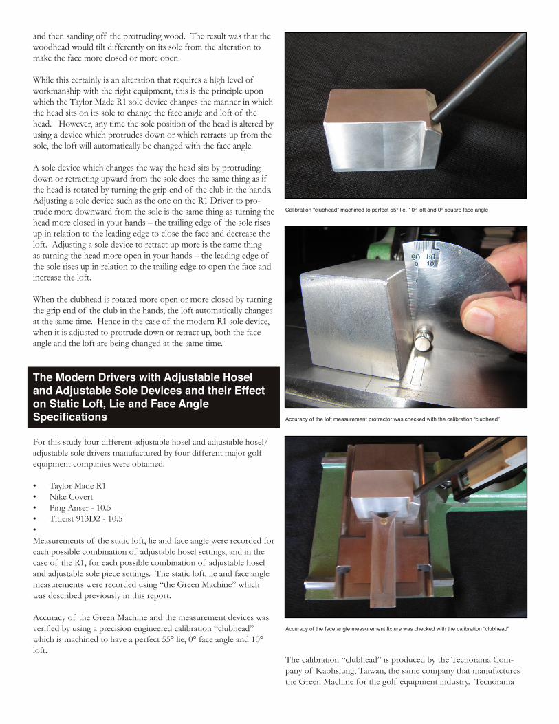
and then sanding off the protruding wood. The result was that the woodhead would tilt differently on its sole from the alteration to make the face more closed or more open.
While this certainly is an alteration that requires a high level of workmanship with the right equipment, this is the principle upon which the Taylor Made R1 sole device changes the manner in which the head sits on its sole to change the face angle and loft of the head. However, any time the sole position of the head is altered by using a device which protrudes down or which retracts up from the sole, the loft will automatically be changed with the face angle.
A sole device which changes the way the head sits by protruding down or retracting upward from the sole does the same thing as if the head is rotated by turning the grip end of the club in the hands. Adjusting a sole device such as the one on the R1 Driver to pro-trude more downward from the sole is the same thing as turning the head more closed in your hands – the trailing edge of the sole rises up in relation to the leading edge to close the face and decrease the loft. Adjusting a sole device to retract up more is the same thing as turning the head more open in your hands – the leading edge of the sole rises up in relation to the trailing edge to open the face and increase the loft.
When the clubhead is rotated more open or more closed by turning the grip end of the club in the hands, the loft automatically changes at the same time. Hence in the case of the modern R1 sole device, when it is adjusted to protrude down or retract up, both the face angle and the loft are being changed at the same time.
The Modern Drivers with Adjustable Hosel and Adjustable Sole Devices and their Effect on Static Loft, Lie and Face Angle Specifications
For this study four different adjustable hosel and adjustable hosel/adjustable sole drivers manufactured by four different major golf equipment companies were obtained. • Taylor Made R1 • Nike Covert• Ping Anser - 10.5• Titleist 913D2 - 10.5 • Measurements of the static loft, lie and face angle were recorded for each possible combination of adjustable hosel settings, and in the case of the R1, for each possible combination of adjustable hosel and adjustable sole piece settings. The static loft, lie and face angle measurements were recorded using “the Green Machine” which was described previously in this report.
Accuracy of the Green Machine and the measurement devices was verified by using a precision engineered calibration “clubhead” which is machined to have a perfect 55° lie, 0° face angle and 10° loft.
The calibration “clubhead” is produced by the Tecnorama Com-pany of Kaohsiung, Taiwan, the same company that manufactures the Green Machine for the golf equipment industry. Tecnorama
Calibration “clubhead” machined to perfect 55° lie, 10° loft and 0° square face angle
Accuracy of the loft measurement protractor was checked with the calibration “clubhead”
Accuracy of the face angle measurement fixture was checked with the calibration “clubhead”

offers this special calibration “clubhead” with the Green Machine to ensure the accuracy of the machine and accompanying devices for lie, loft and face angle measurement.
Driver Head Position for Specifications Measurement
All four of the drivers in this study are manufactured with the face scorelines parallel to the ground line tangent to the center of the sole from toe to heel. Therefore, the position of each head for proper lie angle position was achieved by tilting each driver head in the Green Machine so the center of the sole from toe to heel touched the base of the machine with the bottom scoreline set par-allel to the base of the machine. Assurance of the parallel position of the scorelines to the base of the machine was assisted by the use of the straight edge slide that comes with the Green Machine.
(Note: In all cases, great care was taken to position the heads in the machine with the scorelines parallel to the base of the machine. If the photos look a little different in this aspect, it is only because of a slight tilt of the hand held camera)
The sole position for proper face angle and loft measurement was very carefully determined by allowing each driver to sit flat on its sole on a flat surface in the proper lie position and carefully noting the exact area of contact with the flat surface in the face to back plane of the sole. The point of contact on the sole was marked and duplicated for each measurement.
Correct face to back sole touch position for the Nike Covert Driver is on the only flat surface of the sole due to the ascending rear cavity shape
Correct face to back sole touch position for the Titleist 913D2 Driver is on the widest flat sole surface slightly forward of the center of the sole
Correct face to back sole touch position for the Ping Anser Driver is on the largest flat surface in the center of the sole
Correct face to back sole touch position for the Taylor Made R1 is defined by the twin touch points of the front sole and the rear protruding adjustable sole piece

The measurements for face angle, lie angle and loft for each possi-ble hosel position and hosel + sole piece position were made as pre-cisely as my experience in clubhead design enables me to do. I have been designing clubhead models since 1986. From 1986 to present I have designed more than 350 different models of clubheads so I have a depth of experience in clubhead specification measurement that few have in the golf industry. In addition, at times in my career I have also been asked by two of the largest clubhead production factories to teach proper clubhead specs measurement techniques to the workers in their inspection and tooling departments. With these experiences, my ability to determine the proper clubhead position-ing and to accurately measure clubhead specifications is as reliable as can be found in the golf equipment industry.
Modern Adjustable Hosel / Adjustable Sole Driver Mea-surements
1. Taylor Made R1 Driver
The Taylor Made R1 driver head is offered in a single model which the company says can be adjusted for loft between 8° and 12° and adjusted for face angle between 3° open and 3° closed using the sole adjustable piece. The hosel device has 12 different positions for loft adjustment, the sole piece has 7 different positions for face angle for a total of 84 possible adjustment positions for combina-tions of loft, lie and face angle. While it is not stated by the com-pany, they also claim a lie position change is possible through the designation on the adjustable hosel piece for U (upright) after two of the lofts (9.5U & 10.5U).
The measurements for loft, lie and face angle for each of the 84 different possible combinations of the hosel and sole adjustable devices are as follows:
TAYLOR MADE R1 MEASUREMENTSHosel
SettingSole
SettingFace Angle
Loft Angle
Lie Angle
8.0 N 6.5 open 11.25 59.25
8.0 / 9.5U N 7.0 open 11.5 60.5
9.5U N 6.75 open 11.5 61.5
9.5U / 10.5U
N 5.0 open 11.5 62.5
10.5U N 3.0 open 11.5 62.5
10.5U / 12.0
N 0.75 open 11.5 62.0
12 N 0.75 closed
11.5 61.25
12.0 / 10.5 N 1.25 closed
11.5 60.25
10.5 N 0.25 closed
11.5 59.25
10.5 / 9.5 N 1.0 open 11.25 58.75
9.5 N 3.25 open 11.5 58.25
9.5 / 8.0 N 5.0 open 11.5 58.75
8.0 1 Closed 5.0 open 10.5 60.25
8.0 / 9.5U 1 Closed 5.75 open 10.75 61.25
9.5U 1 Closed 5.0 open 10.5 62.0
9.5U / 10.5U
1 Closed 3.75 open 10.5 62.5
10.5U 1 Closed 1.75 open 10.5 62.75
TAYLOR MADE R1 MEASUREMENTS (CONTINUED)Hosel
SettingSole
SettingFace Angle
Loft Angle
Lie Angle
10.5U / 12.0
1 Closed 0.75 closed
10.5 62.25
12 1 Closed 2.0 closed 10.25 61.25
12.0 / 10.5 1 Closed 2.25 closed
10.5 60.5
10.5 1 Closed 1.5 closed 10.5 59.5
10.5 / 9.5 1 Closed 0.25 open 10.25 58.75
9.5 1 Closed 2.25 open 10.25 59.0
9.5 / 8.0 1 Closed 3.75 open 10.25 59.0
8.0 2 Closed 4.25 open 9.5 59.75
8.0 / 9.5U 2 Closed 4.5 open 9.5 60.25
9.5U 2 Closed 3.75 open 9.5 62
9.5U / 10.5U
2 Closed 2.25 open 9.5 62.5
10.5U 2 Closed 0.75 open 9.5 62.5
10.5U / 12.0
2 Closed 1.75 closed
9.5 62
12 2 Closed 3.25 closed
9.5 61.5
12.0 / 10.5 2 Closed 3.75 closed
9.25 60.25
10.5 2 Closed 3.0 closed 9.5 59.25
10.5 / 9.5 2 Closed 0.75 closed
9.5 58.5
9.5 2 Closed 0.75 open 9.5 58.5
9.5 / 8.0 2 Closed 2.5 open 9.25 59
8.0 3 Closed 3.25 open 9 59.75
8.0 / 9.5U 3 Closed 3.5 open 8.75 61
9.5U 3 Closed 2.5 open 8.75 62.5
9.5U / 10.5U
3 Closed 1.25 open 9 63
10.5U 3 Closed 0.75 closed
9.25 62.75
10.5U / 12.0
3 Closed 3.0 closed 9 62
12 3 Closed 4.75 closed
9.25 61.25
12.0 / 10.5 3 Closed 4.75 closed
9 60.25
10.5 3 Closed 4.0 closed 9 59.25
10.5 / 9.5 3 Closed 2.75 closed
9 59
9.5 3 Closed 0.5 closed 9 58.5
9.5 / 8.0 3 Closed 1.5 open 9.25 58.5
8.0 1 Open > 8 open° 12 60
8.0 / 9.5U 1 Open > 8 open° 11.5 61
9.5U 1 Open 7.75 open 11.75 61.75
9.5U / 10.5U
1 Open 6.75 open 11.5 62.25
10.5U 1 Open 4.25 open 11.5 62.75
10.5U / 12.0
1 Open 2.5 open 12 62.75
12 1 Open 0.75 closed
12 62
12.0 / 10.5 1 Open 0.25 closed
12 60.75
10.5 1 Open 0.25 open 11.5 59.5
10.5 / 9.5 1 Open 2.5 open 12 59

Note: The specifications measurement machine has a limit of 8° open for the face angle measurement
Note 2: Slight variations for the loft measurement within each com-bination of hosel to sole settings are explained by the fact that as the face angle changes dramatically, the head can tilt sightly different in the machine.
2. Nike Covert Driver
As with the Taylor Made Driver, Nike only offers one driver model with the claim that all lofts from 8.5° to 12.5° in 1° increments can
be achieved with the one model via the hosel adjustable device. In addition, the company claims that the face angle can also be customized in three different settings for Left, Right and Neutral on a second rotational collar on the adjustable hosel device. Nike does not state a specific face angle specification for the Covert. The company says nothing about a lie angle change being possible from their adjustable hosel device. With the five different loft settings and three face angle positions, the Covert driver can be adjusted to 15 different positions.
The measurements for loft, lie and face angle for the Nike Covert Driver are as follows:
Note: The specifications measurement machine has a limit of 8° open for the face angle measurement
Note 2: Slight variations for the loft measurement within each single face angle setting over all loft positions are explained by the fact that as the face angle changes dramatically, the head tilts slightly different on its face to back sole plane
3. Titleist 913D2 – 10.5 Driver
Unlike Taylor Made and Nike, Titleist manufactures the 913D2 in different loft models. The company’s adjustable hosel device has a double ring setting, not unlike the Nike Covert hosel device. Un-like the other companies, Titleist claims that their hosel device will allow adjustment of the lie in addition to the loft. The company says nothing about the face angle, and in the full list of specifica-tions for the driver on their website, they do not state a face angle specification. There are a total of 16 different combinations of the adjustable hosel device which are noted by a combination of letters and numbers, A to D and 1 to 4. The code designations for the adjustable hosel settings are translated into a loft and lie via a chart that Titleist has created.
NIKE COVERT MEASUREMENTSLower Ring Loft
Setting
Upper Ring Face
Setting
Face Angle
Loft
Angle
Lie
Angle
8.5 Right > 8 open° 12.5 59.5
9.5 Right > 8 open° 12.75 60.5
10.5 Right 6.5 open 12.5 61
11.5 Right 6 open 12.5 61
12.5 Right 5 open 12.5 60.25
8.5 Neutral > 8 open° 12.5 60.25
9.5 Neutral 7.25 open 12 60.5
10.5 Neutral 6 open 12.5 60.75
11.5 Neutral 3.75 open 12.5 60
12.5 Neutral 4 open 12.75 59.5
8.5 Left 7.25 open 12 59.75
9.5 Left 6.25 open 12.5 60
10.5 Left 4.5 open 13 60
11.5 Left 3.5 open 12.75 60
12.5 Left 3.25 open 13 59.5
TAYLOR MADE R1 MEASUREMENTS (CONTINUED)Hosel
SettingSole
SettingFace Angle
Loft Angle
Lie Angle
9.5 1 Open 4.5 open 11.75 58.5
9.5 / 8.0 1 Open 6.25 open 11.5 59
8.0 2 Open > 8 open° 12 59.5
8.0 / 9.5U 2 Open > 8 open° 12 60
9.5U 2 Open > 8 open° 12 61.5
9.5U / 10.5U
2 Open 7.25 open 12.25 62
10.5U 2 Open 5.75 open 12.5 63.25
10.5U / 12.0
2 Open 3.5 open 12.75 62.5
12 2 Open 1.75 open 12.25 61.75
12.0 / 10.5 2 Open 0.75 open 12 60
10.5 2 Open 1.75 open 12 59.5
10.5 / 9.5 2 Open 3.75 open 12 59.25
9.5 2 Open 5.25 open 12 58.5
9.5 / 8.0 2 Open 7.0 open 12.25 58.25
8.0 3 Open > 8 open° 13 59.5
8.0 / 9.5U 3 Open > 8 open° 12.75 60.25
9.5U 3 Open > 8 open° 12.75 62
9.5U / 10.5U
3 Open > 8 open° 13 62.5
10.5U 3 Open 7.75 open 13 63
10.5U / 12.0
3 Open 5.25 open 13 62.5
12 3 Open 3.25 open 12.75 62
12.0 / 10.5 3 Open 2.75 open 13 60.75
10.5 3 Open 3.25 open 13.25 59.75
10.5 / 9.5 3 Open 4.75 open 13.25 58.75
9.5 3 Open 6.75 open 13 58.25
9.5 / 8.0 3 Open > 8 open° 13 58.25
8.0 1 Open > 8 open° 12 60
8.0 / 9.5U 1 Open > 8 open° 11.5 61
9.5U 1 Open 7.75 open 11.75 61.75
9.5U / 10.5U
1 Open 6.75 open 11.5 62.25
10.5U 1 Open 4.25 open 11.5 62.75
10.5U / 12.0
1 Open 2.5 open 12 62.75
12 1 Open 0.75 closed
12 62

In the measurements for the 913D2, rather than use their somewhat confusing chart, we compared the chart entries to the company’s published loft and lie specs to translate the chart settings into actual loft and lie specifications that each setting of the hosel device is claimed by the company to achieve. The Titleist 913D2 measurements for loft, lie and face angle are as follows:
4. PING Anser Driver – 10.5
Similar to the Titleist 913D2 but unlike the Covert and R1, the Ping Anser driver is made in different loft versions from 8.5° to 12°. The company claims that their adjustable hosel device is used strictly to make loft adjustments of +1/2° or -1/2° from each model’s spec loft. No mention is made of a change in face angle or in lie angle from the adjustable hosel device. The Ping adjustable hosel device has but three different settings for the loft adjustment, noted by symbols of • (the head model’s spec loft) , + (add 1/2 ° loft), and – (reduce ½° loft).
The PING Anser 10.5 measurements for loft, lie and face angle for each of the three settings on the adjustable hosel device are as follows:
Conclusion
Upon reading how far off the loft, lie and face angle specifications are from each company’s stated specifications, it would be logical for loyal followers of these golf equipment companies to chal-lenge the measurements in this report as either biased or incorrect. I assure you that the measurements are exactly as reported based on the experience gained in 27 years as a clubhead designer and as a serious student of the technology of golf equipment. The
measurements were performed using the accepted manner of positioning a driver head for accurate loft, lie and face angle measurement as practiced for many decades by every clubhead production factory I have experience with, several which have produced clubheads for the major golf equip-ment companies for many years. I will admit I was so amazed at how far off these measurements were from each company’s stated specifications that I repeated the measurements for each driver for every combination of adjustable device settings to be doubly sure of the accuracy of the specification measurements. These ARE the static loft, lie and face angle measurements for these drivers when the driver heads are placed in the specs measurement machine in the manner that has been practiced in this industry
for many, many years.
The fact that the loft angle does NOT change from any of the adjustable HOSEL devices does not surprise me. I expected this would be the case based on my experience in manufacturing wood-en woodheads and from my experience in having created the first adjustable hosel device for metal woods. You can definitely change the lie angle and the face angle by changing the angle of the shaft into the hosel and into the head, but you simply cannot change the loft of a woodhead through a change in the angle of the shaft using such an adjustable hosel device.
I was also surprised to see the face angle measurements be as open as many of the combinations of the adjustable hosel devices produced on the heads. I must also add that when a head measured substantially open in the Green Machine, it also looked very open when placed on a flat surface to simulate the natural resting address position of the head.
Only with the adjustable sole protrusion piece on the sole of the Taylor Made R1 can you change the loft, but in doing so you also change the face angle at the same time. As can be seen in the measurements, the measured face angle was rarely close to the face angle as designated by the marks on the adjustable sole device. Rarely, even with the additional influence of the R1 sole protrusion device, did the loft and face angle end up being close to what the company stated. As the head is tilted more closed by the sole piece protruding more from the sole, the loft automatically decreases, and as the head is tilted more open by the sole piece receding more
TITLEIST 913D2 – 10.5 MEASUREMENTSHosel
SettingTitleist stated Loft
Measured Loft
Titleist stated
Lie
Measured Lie
Titleist stated Face
Angle
Measured Face Angle
A1 10.50 14.50 58.50 60.00 Not Listed 6.75 open
A2 10.50 14.50 60.00 62.25 Not Listed 7.0 open
A3 12.00 14.50 60.00 62.25 Not Listed 3.25 open
A4 12.00 14.50 58.50 60.00 Not Listed 2.5 open
B1 10.50 14.50 57.75 59.25 Not Listed 5.75 open
B2 10.50 14.50 59.25 61.00 Not Listed 6.5 open
B3 12.00 14.50 59.25 61.00 Not Listed 3.25 open
B4 12.00 14.50 57.75 60.00 Not Listed 2.75 open
C1 9.75 14.50 57.75 59.25 Not Listed 6.75 open
C2 9.75 14.50 59.25 61.00 Not Listed 8.0 open
C3 11.25 14.50 59.25 61.00 Not Listed 3.25 open
C4 11.25 14.50 57.75 59.25 Not Listed 3.5 open
D1 9.75 14.50 58.50 59.50 Not Listed 7.0 open
D2 9.75 14.50 60.00 61.25 Not Listed 7.75 open
D3 11.25 14.50 60.00 61.25 Not Listed 3.75 open
D4 11.25 14.50 58.50 60.00 Not Listed 4.0 open
PING ANSER – 10.5 MEASUREMENTSHosel
SettingMeasured
LoftMeasured
LieMeasured
Face Angle
• 14.5 60.0 3.5 open
+ 14.5 60.0 6.5 open
– 14.5 59.0 6.0 open

upward, the loft automatically increases.
The ONLY way any of these drivers can come close to playing at the lofts stated on each company’s hosel device is if the golfer manually rotates the clubface until the rotation achieves the stated loft. But then the golfer has to manually HOLD the club off the ground, and as carefully as possible, hold the clubhead in that posi-tion when addressing the shot and when commencing the swing to hit the shot. To truly achieve each stated loft, the clubhead would have to be rotated into a different position, and again, HELD manually by the golfer in that position. In performing a manual rotation of the head to achieve the stated loft, the face angle will also change. Manually holding the driver in a specific loft position is very difficult to do with any level of accuracy. How many golf-ers can tell if they have rotated the clubface to a difference of 1° or even 2° of loft?
That’s why the commonly accepted manner of playing a driver has been to sole the club on the ground so it adopts its static specifica-tions for loft and face angle, taking the grip, and starting the swing. No golfer should be or can be expected to have to rotate the club-head to a specific position and hold the head in that position before starting the swing.
Following is a photo of one of the drivers that shows the general position for how each of these adjustable hosel drivers would have to be positioned and manually held so as to make the loft be closer to what the hosel device says it is. Rotating the face around to change the loft also changes the face angle. So even if the golfer managed to guess that he has manually rotated the face to achieve a specific loft, the face angle is locked in whatever position to go with that - which may not be a proper fit for the golfer’s horizontal launch angle and accuracy.
By far, the vast majority of golfers, even the majority of tour pros, set the driver down to rest on its sole when they address the ball to hit a tee shot, and leave the driver sitting on its sole when they start the swing to hit the shot. Doing that will result in these drivers set-ting up to the ball with the static specifications measured and stated in this report.
That is how golfers are supposed to set up to the ball with a driver
or any wood for that matter. The whole reason a clubhead designer and his production factory painstakingly try to produce driver and woodheads to accurate static specifications is to allow the golfer to address the ball with as close to those specifications as possible so that the static specs of the club combine with the swing character-istics of the golfer to produce a specific shot result. Cause and Effect.
Static Clubhead Specifications + Golfer Swing Characteristics = Shot Results
Being a clubhead designer since 1986 with more experience in all areas of clubhead design and Clubfitting research than perhaps anyone in the game, I have complete respect for the engineering and design capability of the major golf club companies. I sincerely do. To use that engineering ability to create beautifully made driver heads which are very far off from achieving the specifications stated by each company is of no help to golfers who simply wish to acquire the very best golf clubs with which to play this great game to the best of their ability.
The best golf clubs for any golfer will be built with clubheads which possess static specifications which have been determined by the golf company and/or an experienced clubfitter to be able to produce the most consistent shot results when subjected to the swing characteristics of each golfer. If a golfer cannot rely on the static specifications of the clubhead to be what they are stated to be, achieving the most consistent shot results becomes a very disor-ganized trial and error process.
For any of the adjustable hosel drivers to be able to achieve close to the lofts claimed by the company, the driver head would have to be manually rotated and held by the golfer. This is not how drivers have been played by the vast majority of golfers so this type of manually held address position is simply not feasible for the majority of golfers to adopt.