
A Tail of Two Peaks: Troubleshooting Poor Peak …...Agilent J&W DB-624 Column QC Test Mix Column:...
68
Agilent Restricted 1 A Tale of Two Peaks: Troubleshooting Poor Peak Shape Alexander Ucci January 17, 2019
Transcript of A Tail of Two Peaks: Troubleshooting Poor Peak …...Agilent J&W DB-624 Column QC Test Mix Column:...

Agilent Restricted1
A Tale of Two Peaks:Troubleshooting Poor Peak Shape
Alexander UcciJanuary 17, 2019
Page 2
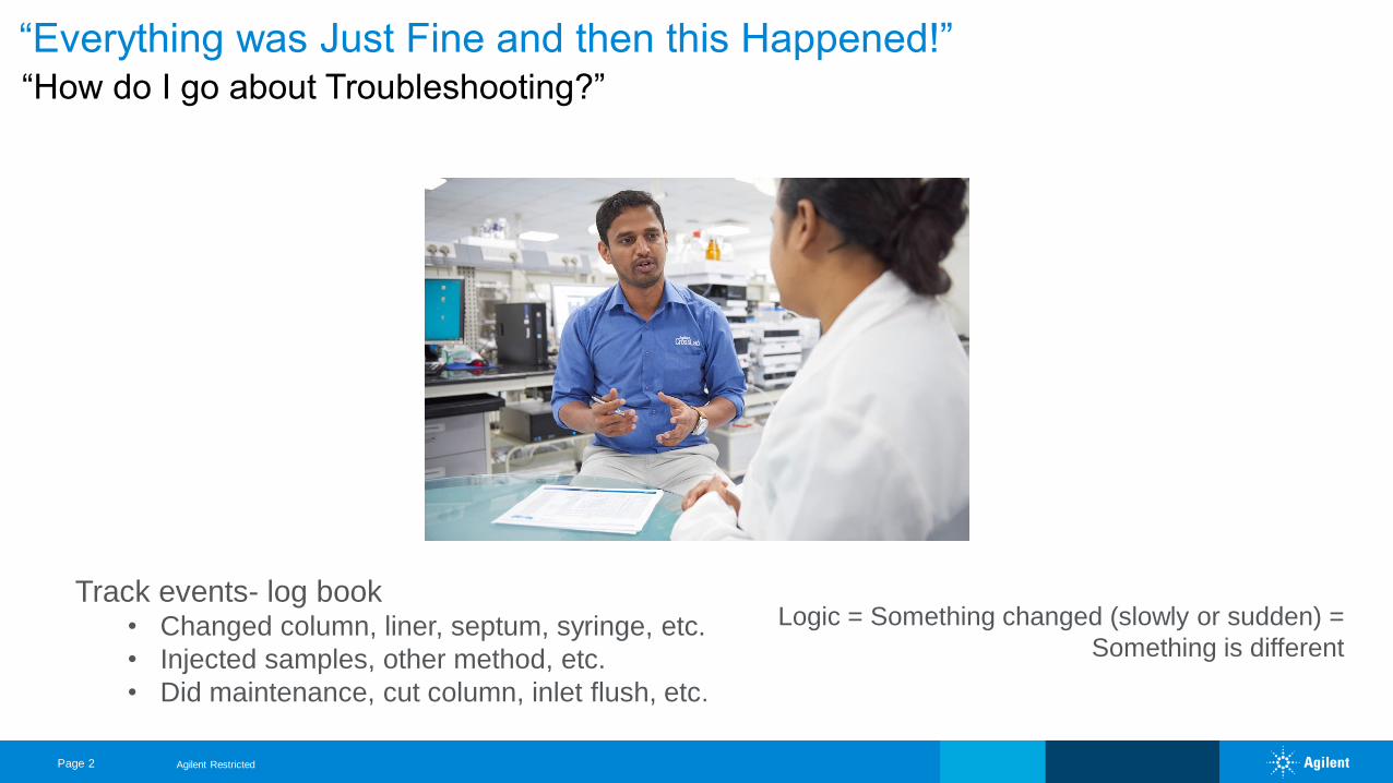
“Everything was Just Fine and then this Happened!” “How do I go about Troubleshooting?”
Logic = Something changed (slowly or sudden) =
Something is different
Agilent Restricted
Track events- log book• Changed column, liner, septum, syringe, etc.
• Injected samples, other method, etc.
• Did maintenance, cut column, inlet flush, etc.
Page 3
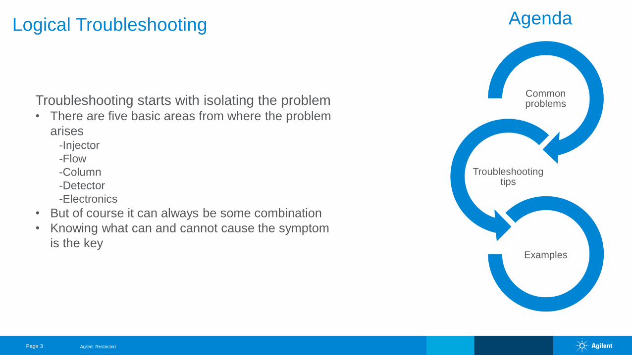
Logical Troubleshooting
Common problems
Troubleshooting tips
Examples
Agenda
Agilent Restricted
Troubleshooting starts with isolating the problem• There are five basic areas from where the problem
arises-Injector
-Flow
-Column
-Detector
-Electronics
• But of course it can always be some combination
• Knowing what can and cannot cause the symptom
is the key
Page 4
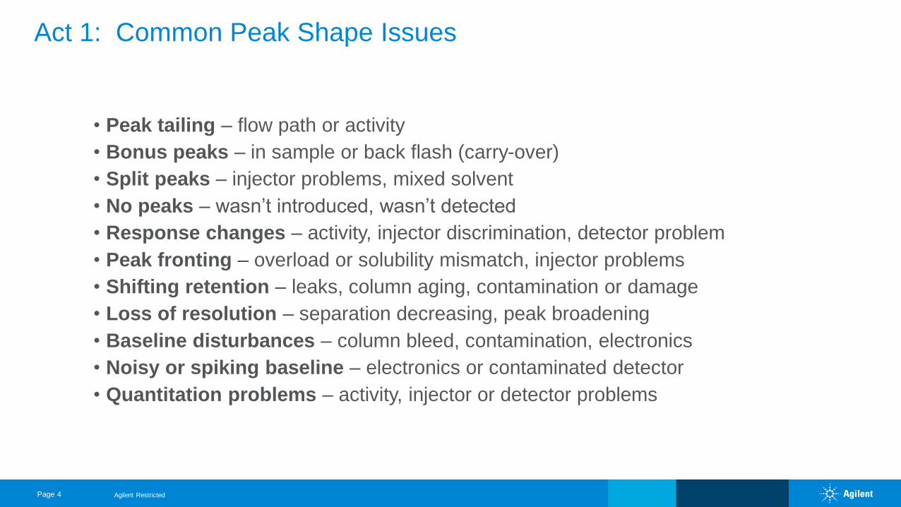
• Peak tailing – flow path or activity
• Bonus peaks – in sample or back flash (carry-over)
• Split peaks – injector problems, mixed solvent
• No peaks – wasn’t introduced, wasn’t detected
• Response changes – activity, injector discrimination, detector problem
• Peak fronting – overload or solubility mismatch, injector problems
• Shifting retention – leaks, column aging, contamination or damage
• Loss of resolution – separation decreasing, peak broadening
• Baseline disturbances – column bleed, contamination, electronics
• Noisy or spiking baseline – electronics or contaminated detector
• Quantitation problems – activity, injector or detector problems
Act 1: Common Peak Shape Issues
Agilent Restricted
Page 5
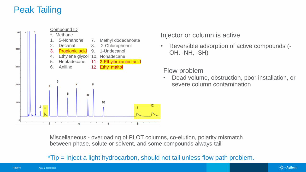
Peak Tailing
Injector or column is active
• Reversible adsorption of active compounds (-OH, -NH, -SH)
Flow problem • Dead volume, obstruction, poor installation, or
severe column contamination
Miscellaneous - overloading of PLOT columns, co-elution, polarity mismatch between phase, solute or solvent, and some compounds always tail
*Tip = Inject a light hydrocarbon, should not tail unless flow path problem.
Agilent Restricted
Compound ID
*. Methane
1. 5-Nonanone
2. Decanal
3. Propionic acid
4. Ethylene glycol
5. Heptadecane
6. Aniline
7. Methyl dodecanoate
8. 2-Chlorophenol
9. 1-Undecanol
10. Nonadecane
11. 2-Ethylhexanoic acid
12. Ethyl maltol
Page 6
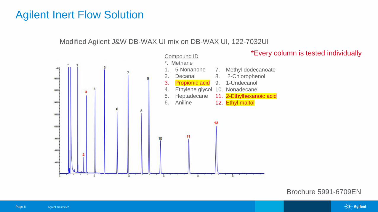
Brochure 5991-6709EN
Agilent Inert Flow Solution
Agilent Restricted
Compound ID
*. Methane
1. 5-Nonanone
2. Decanal
3. Propionic acid
4. Ethylene glycol
5. Heptadecane
6. Aniline
7. Methyl dodecanoate
8. 2-Chlorophenol
9. 1-Undecanol
10. Nonadecane
11. 2-Ethylhexanoic acid
12. Ethyl maltol
Modified Agilent J&W DB-WAX UI mix on DB-WAX UI, 122-7032UI
*Every column is tested individually
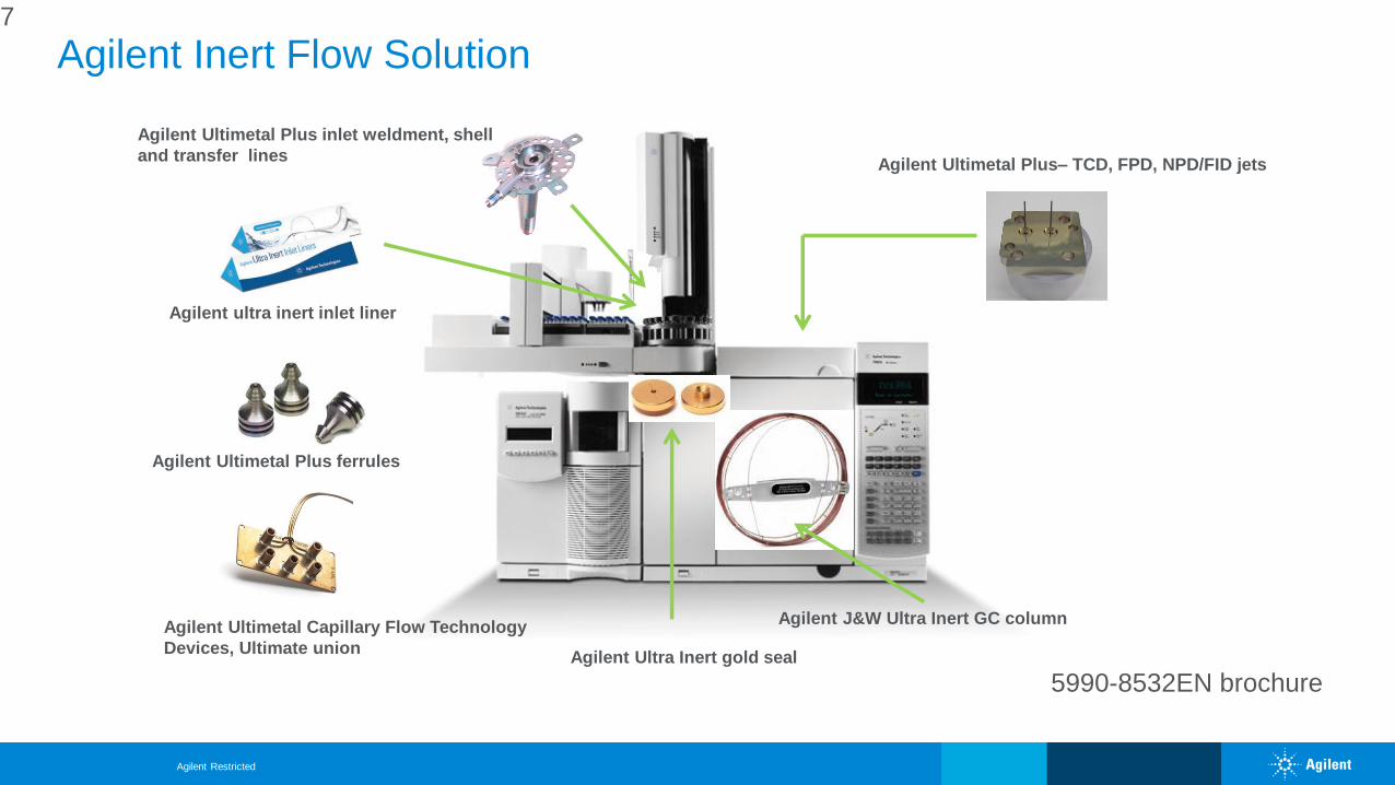
Agilent Inert Flow Solution
Agilent Ultimetal Plus– TCD, FPD, NPD/FID jets
Agilent Ultimetal Capillary Flow Technology
Devices, Ultimate union
Agilent J&W Ultra Inert GC column
Agilent Ultra Inert gold seal
Agilent ultra inert inlet liner
Agilent Ultimetal Plus ferrules
Agilent Ultimetal Plus inlet weldment, shell
and transfer lines
7
5990-8532EN brochure
Agilent Restricted
Page 8
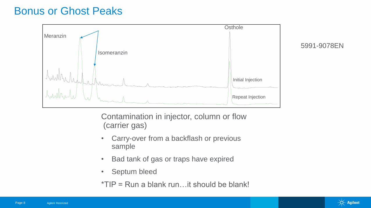
Bonus or Ghost Peaks
Contamination in injector, column or flow (carrier gas)
• Carry-over from a backflash or previous sample
• Bad tank of gas or traps have expired
• Septum bleed
*TIP = Run a blank run…it should be blank!
Initial Injection
Repeat Injection
Meranzin
Isomeranzin
Osthole
5991-9078EN
Agilent Restricted
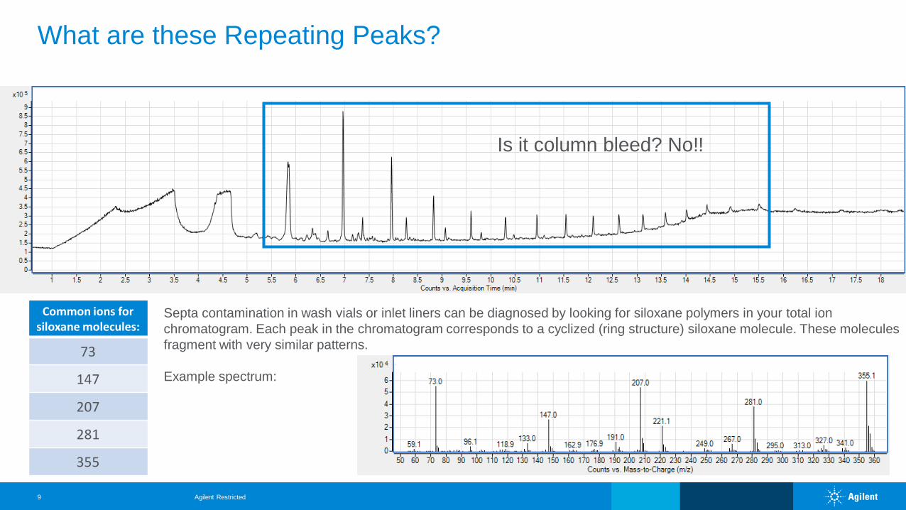
What are these Repeating Peaks?
Agilent Restricted9
Septa contamination in wash vials or inlet liners can be diagnosed by looking for siloxane polymers in your total ion
chromatogram. Each peak in the chromatogram corresponds to a cyclized (ring structure) siloxane molecule. These molecules
fragment with very similar patterns.
Example spectrum:
Common ions for siloxane molecules:
73
147
207
281
355
Is it column bleed? No!!
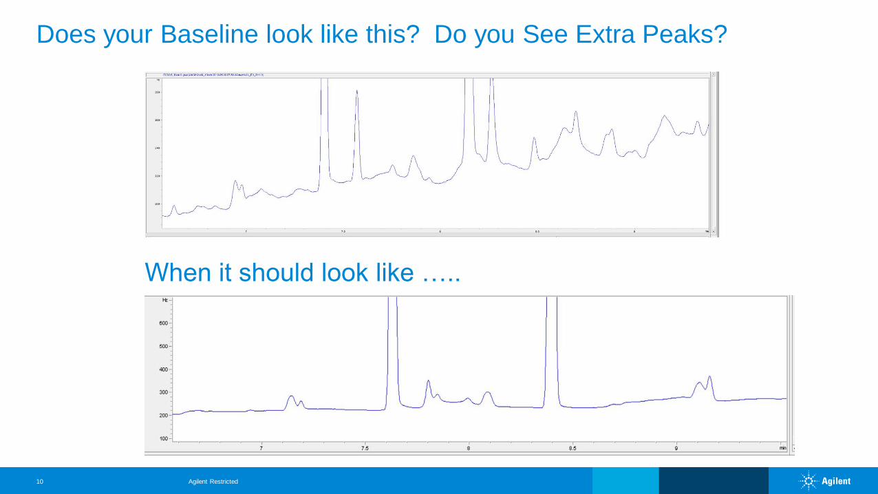
Does your Baseline look like this? Do you See Extra Peaks?
Agilent Restricted10
When it should look like …..
1x10
-1
-0.8
-0.6
-0.4
-0.2
0
0.2
0.4
0.6
0.8
1
1.2
1.4
1.6
1.8
2
2.2
2.4
2.6
2.8
3
3.2
3.4
3.6
3.8
4
4.2
+ EIC(93.1) Scan Extract_00003.D
Counts (%) vs. Acquisition Time (min)
3 3.5 4 4.5 5 5.5 6 6.5 7 7.5 8 8.5 9 9.5 10 10.5 11 11.5 12 12.5 13 13.5 14 14.5 15 15.5 16 16.5 17 17.5 18 18.5 19 19.5 20
Agilent Restricted11
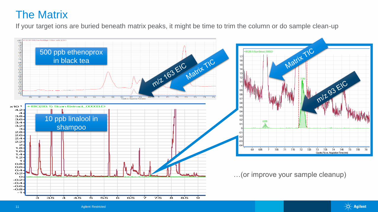
If your target ions are buried beneath matrix peaks, it might be time to trim the column or do sample clean-up
The Matrix
500 ppb ethenoprox
in black tea
10 ppb linalool in
shampoo
-0.4
-0.3
-0.2
-0.1
0
0.1
0.2
0.3
0.4
0.5
0.6
0.7
0.8
0.9
1
1.1
1.2
1.3
1.4
1.5
1.6
1.7
+ EIC(93.1) Scan Extract_00003.D
7.210
6.978
Counts (%) vs. Acquisition Time (min)
6.9 6.95 7 7.05 7.1 7.15 7.2 7.25 7.3 7.35 7.4 7.45 7.5 7.55 7.6 7.65 7.7 7.75 7.8 7.85 7.9
…(or improve your sample cleanup)
Agilent Restricted12
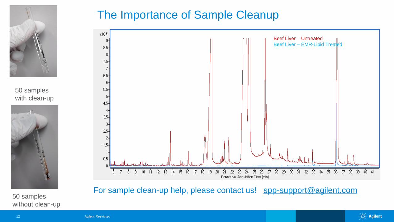
Beef Liver – Untreated
Beef Liver – EMR-Lipid Treated
The Importance of Sample Cleanup
For sample clean-up help, please contact us! [email protected]
50 samples
with clean-up
50 samples
without clean-up
Page 13
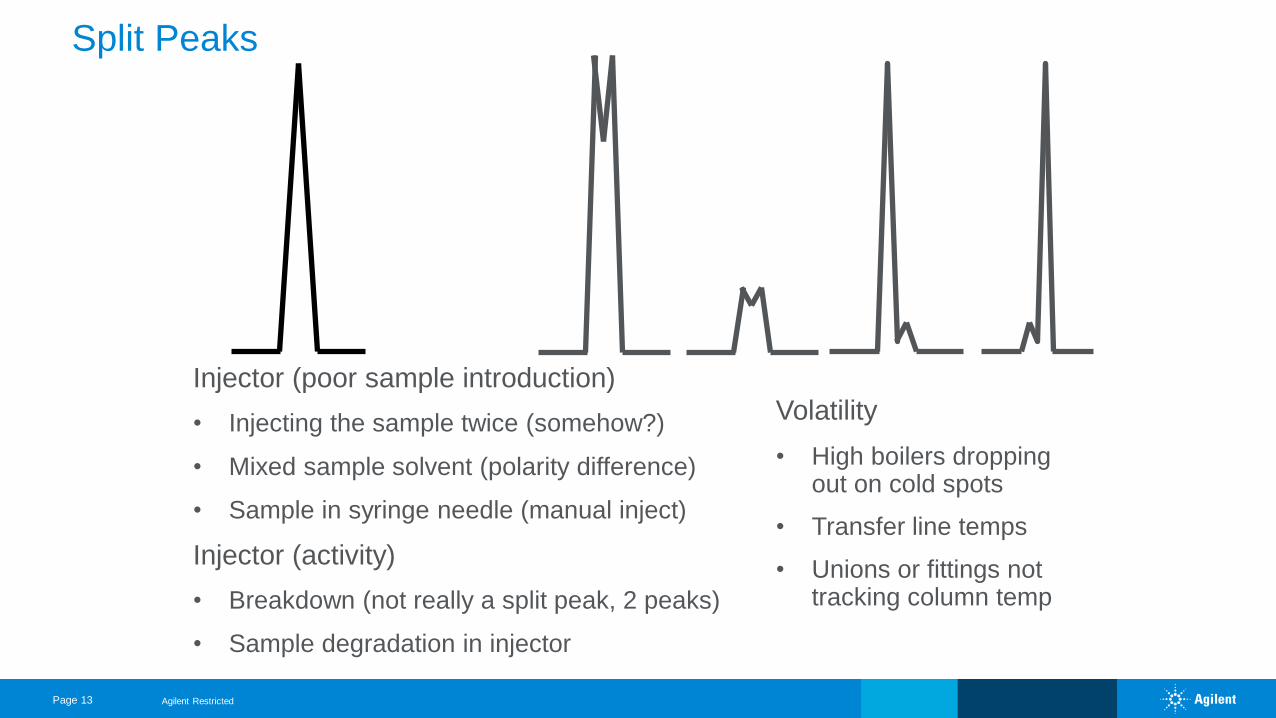
Split Peaks
Injector (poor sample introduction)
• Injecting the sample twice (somehow?)
• Mixed sample solvent (polarity difference)
• Sample in syringe needle (manual inject)
Injector (activity)
• Breakdown (not really a split peak, 2 peaks)
• Sample degradation in injector
Volatility
• High boilers dropping out on cold spots
• Transfer line temps
• Unions or fittings not tracking column temp
Agilent Restricted
Page 14
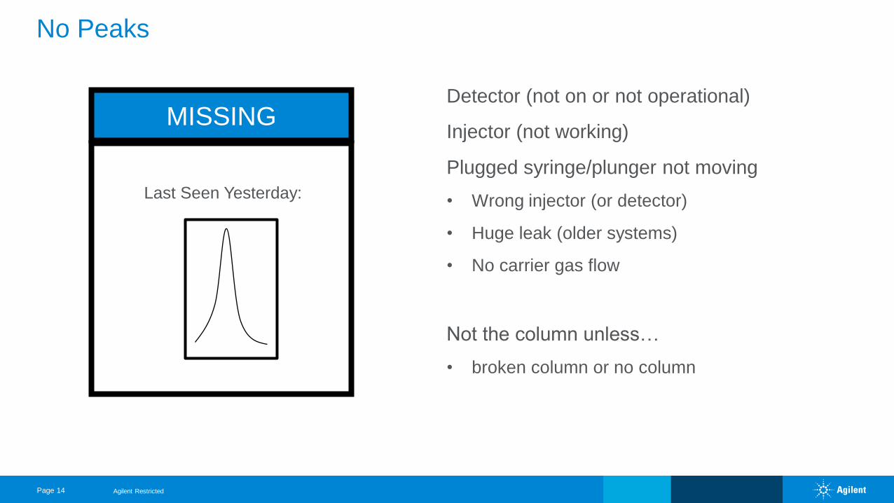
No Peaks
Detector (not on or not operational)
Injector (not working)
Plugged syringe/plunger not moving
• Wrong injector (or detector)
• Huge leak (older systems)
• No carrier gas flow
Not the column unless…
• broken column or no column
MISSING
Last Seen Yesterday:
Agilent Restricted
Page 15
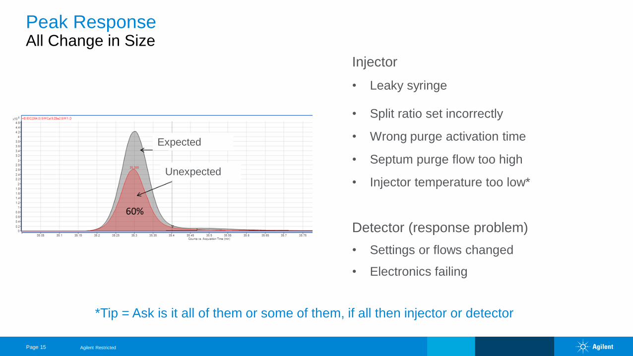
Peak ResponseAll Change in Size
Detector (response problem)
• Settings or flows changed
• Electronics failing
• Split ratio set incorrectly
• Wrong purge activation time
• Septum purge flow too high
• Injector temperature too low*
Injector
• Leaky syringe
*Tip = Ask is it all of them or some of them, if all then injector or detector
Expected
Unexpected
Agilent Restricted
Page 16
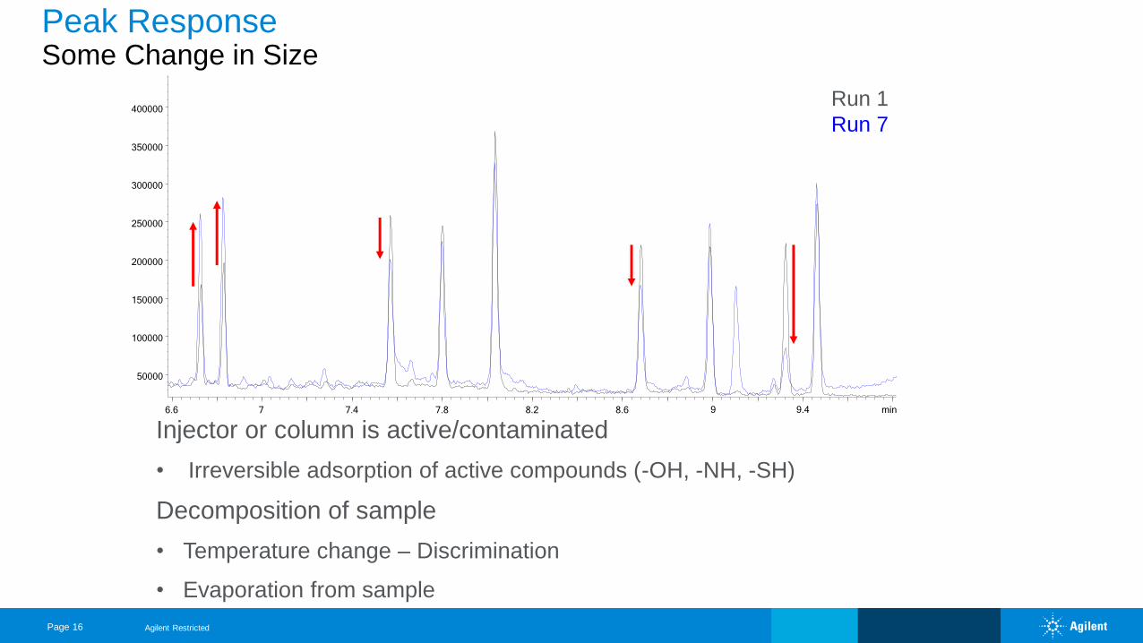
Injector or column is active/contaminated
• Irreversible adsorption of active compounds (-OH, -NH, -SH)
Decomposition of sample
• Temperature change – Discrimination
• Evaporation from sample
Peak ResponseSome Change in Size
6.6 7 7.4 7.8 8.2 8.6 9 9.4
50000
100000
150000
200000
250000
300000
350000
400000
min
Run 1
Run 7
Agilent Restricted
Page 17
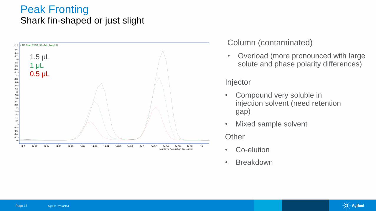
Peak FrontingShark fin-shaped or just slight
Column (contaminated)
• Overload (more pronounced with large solute and phase polarity differences)
Injector
• Compound very soluble in injection solvent (need retention gap)
• Mixed sample solvent
Other
• Co-elution
• Breakdown
1.5 μL
1 μL
0.5 μL
Agilent Restricted
Page 18
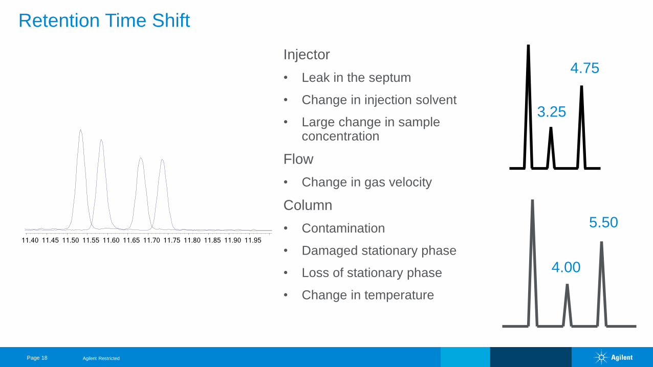
Retention Time Shift
3.25
4.75
4.00
5.50
Injector
• Leak in the septum
• Change in injection solvent
• Large change in sample concentration
Flow
• Change in gas velocity
Column
• Contamination
• Damaged stationary phase
• Loss of stationary phase
• Change in temperature
Agilent Restricted
11.40 11.45 11.50 11.55 11.60 11.65 11.70 11.75 11.80 11.85 11.90 11.95
Page 19
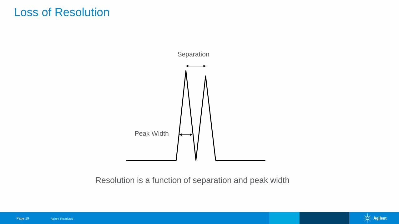
Loss of Resolution
Resolution is a function of separation and peak width
Separation
Peak Width
Agilent Restricted
Page 20
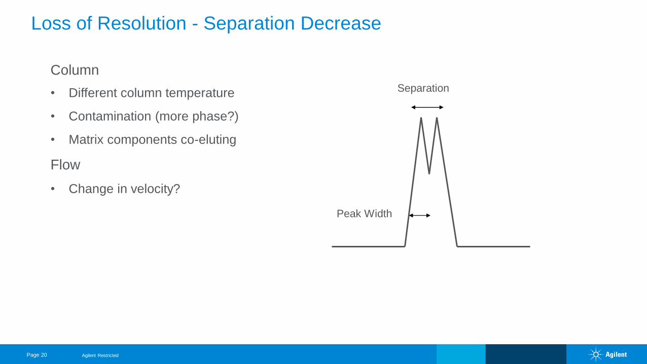
Loss of Resolution - Separation Decrease
Column
• Different column temperature
• Contamination (more phase?)
• Matrix components co-eluting
Flow
• Change in velocity?
Separation
Peak Width
Agilent Restricted
Page 21
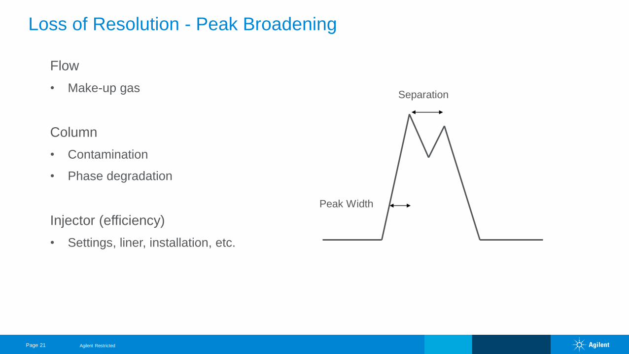
Loss of Resolution - Peak Broadening
Flow
• Make-up gas
Column
• Contamination
• Phase degradation
Injector (efficiency)
• Settings, liner, installation, etc.
Peak Width
Separation
Agilent Restricted
Page 22
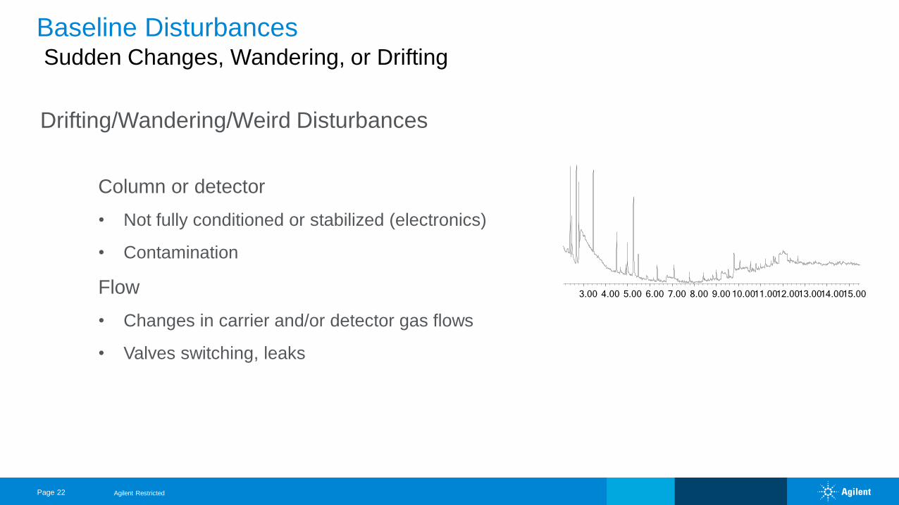
Baseline DisturbancesSudden Changes, Wandering, or Drifting
Column or detector
• Not fully conditioned or stabilized (electronics)
• Contamination
Flow
• Changes in carrier and/or detector gas flows
• Valves switching, leaks
Drifting/Wandering/Weird Disturbances
Agilent Restricted
3.00 4.00 5.00 6.00 7.00 8.00 9.00 10.0011.0012.0013.0014.0015.00
Page 23
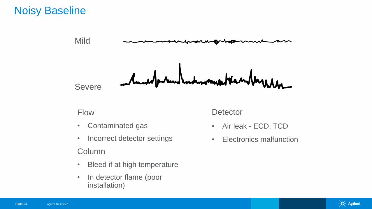
Noisy Baseline
Flow
• Contaminated gas
• Incorrect detector settings
Column
• Bleed if at high temperature
• In detector flame (poor installation)
Mild
Severe
Detector
• Air leak - ECD, TCD
• Electronics malfunction
Agilent Restricted
Page 24
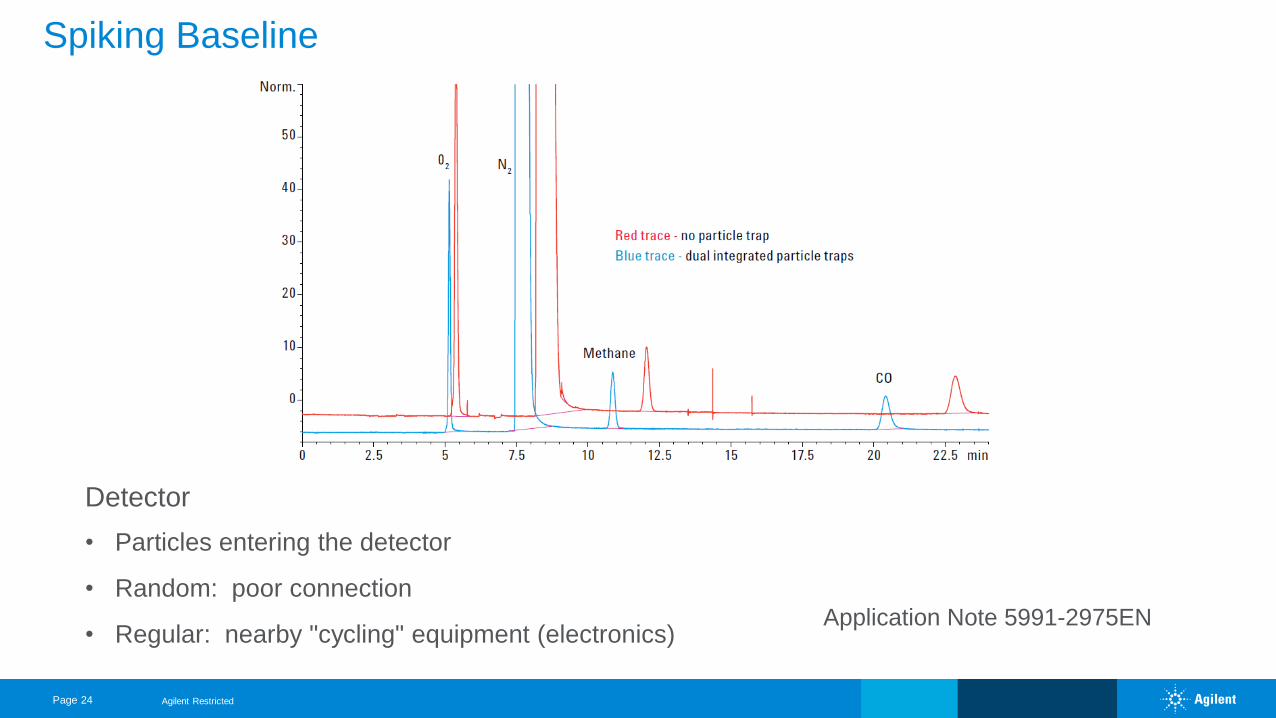
Spiking Baseline
Detector
• Particles entering the detector
• Random: poor connection
• Regular: nearby "cycling" equipment (electronics)Application Note 5991-2975EN
Agilent Restricted
Page 25
Quantitation Problems
Detector
• Poor stability (electronics) or baseline disturbances (contamination)
• Outside detector's linear range or wrong settings
Activity (adsorption) in injector or column
Injector
• Technique, settings, conditions
• Syringe worn
Other
• Co-elution
• Matrix effects
• Sample evaporation – leaky vials
• Sample decomposition
Agilent Restricted
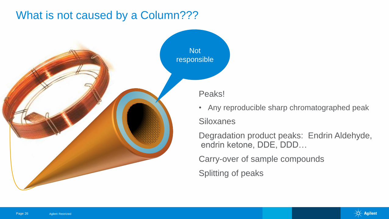
What is not caused by a Column???
Page 26
Not
responsible
Peaks!
• Any reproducible sharp chromatographed peak
Siloxanes
Degradation product peaks: Endrin Aldehyde, endrin ketone, DDE, DDD…
Carry-over of sample compounds
Splitting of peaks
Agilent Restricted
Page 27
Bleed profile: baseline problems
Inject a nonretained peak: peak shape problems
Test mix: all problems
Isolate the components: all problems
Condensation test: baseline problems
Jumper tube test: baseline problems
Act 2: Troubleshooting Tools
Agilent Restricted
Page 28
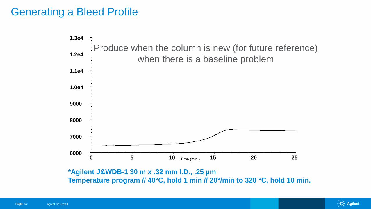
Generating a Bleed Profile
Time (min.)0 5 10 15 20 256000
7000
8000
9000
1.0e4
1.1e4
1.2e4
1.3e4
*Agilent J&WDB-1 30 m x .32 mm I.D., .25 µm
Temperature program // 40°C, hold 1 min // 20°/min to 320 °C, hold 10 min.
Produce when the column is new (for future reference)
when there is a baseline problem
Agilent Restricted
Page 29
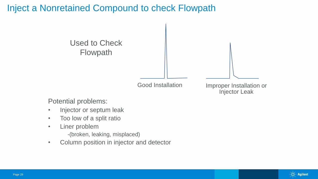
Inject a Nonretained Compound to check Flowpath
Good Installation Improper Installation orInjector Leak
Potential problems:
• Injector or septum leak
• Too low of a split ratio
• Liner problem
-(broken, leaking, misplaced)
• Column position in injector and detector
Used to Check
Flowpath
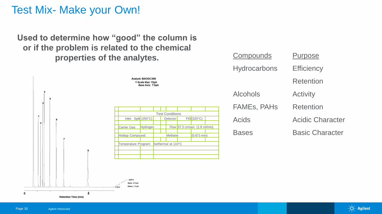
Page 30
Test Conditions
Inlet: Split (250°C) Detector: FID (320°C)
Carrier Gas: Hydrogen Flow: 37.3 cm/sec (1.8 ml/min)
Holdup Compound: Methane (0.671-min)
Temperature Program: Isothermal at 110°C
Test Mix- Make your Own!
Used to determine how “good” the column is
or if the problem is related to the chemical
properties of the analytes. Compounds
Hydrocarbons
Alcohols
FAMEs, PAHs
Acids
Bases
Purpose
Efficiency
Retention
Activity
Retention
Acidic Character
Basic Character
Agilent Restricted
Page 31
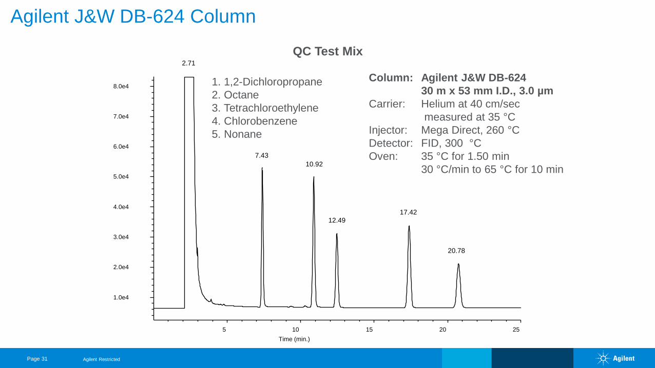
Agilent J&W DB-624 Column
QC Test Mix
Column: Agilent J&W DB-624
30 m x 53 mm I.D., 3.0 µm
Carrier: Helium at 40 cm/sec
measured at 35 °C
Injector: Mega Direct, 260 °C
Detector: FID, 300 °C
Oven: 35 °C for 1.50 min
30 °C/min to 65 °C for 10 min
1. 1,2-Dichloropropane
2. Octane
3. Tetrachloroethylene
4. Chlorobenzene
5. Nonane
5 10 15 20 25
1.0e4
2.0e4
3.0e4
4.0e4
5.0e4
6.0e4
7.0e4
8.0e4
Time (min.)
2.71
7.43
10.92
12.49
17.42
20.78
Agilent Restricted
Page 32
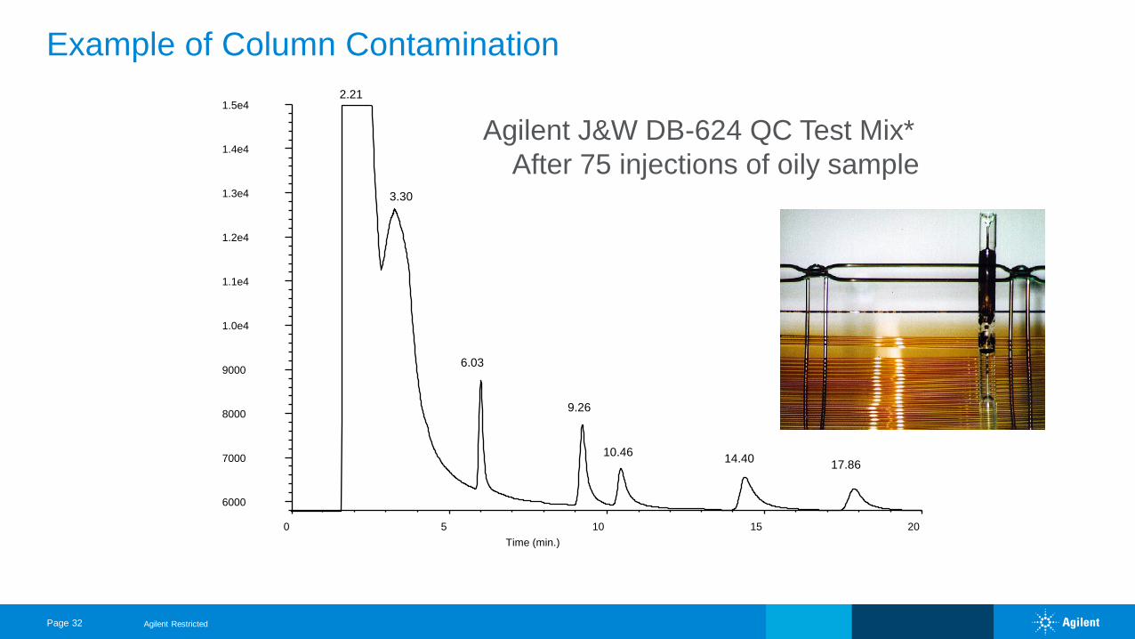
Example of Column Contamination
Agilent J&W DB-624 QC Test Mix*
After 75 injections of oily sample
0 5 10 15 20
6000
7000
8000
9000
1.0e4
1.1e4
1.2e4
1.3e4
1.4e4
1.5e4
Time (min.)
2.21
3.30
6.03
9.26
10.4614.40
17.86
*Temperature program// 35°C hold 1.50 min // 30°/min to 65°C, hold 10 min
Agilent Restricted
Page 33
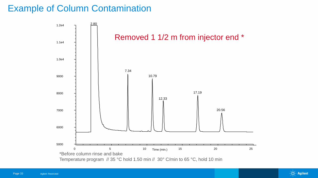
Example of Column Contamination
Removed 1 1/2 m from injector end *
Time (min.)0 5 10 15 20 25
5000
6000
7000
8000
9000
1.0e4
1.1e4
1.2e4 2.80
7.34
10.79
12.33
17.19
20.56
*Before column rinse and bake
Temperature program // 35 °C hold 1.50 min // 30° C/min to 65 °C, hold 10 min
Agilent Restricted
Page 34
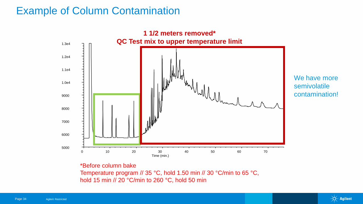
Example of Column Contamination
0 10 20 30 40 50 60 705000
6000
7000
8000
9000
1.0e4
1.1e4
1.2e4
1.3e4
Time (min.)
1 1/2 meters removed*
QC Test mix to upper temperature limit
*Before column bake
Temperature program // 35 °C, hold 1.50 min // 30 °C/min to 65 °C,
hold 15 min // 20 °C/min to 260 °C, hold 50 min
Agilent Restricted
We have more
semivolatile
contamination!
Page 35
Condensation Test
Used* to isolate the cause of:
• Erratic baselines
• Ghost peaks or carry-over
*Use when problems are worse after periods of GC non-use
Agilent Restricted
Page 36
Condensation Test
Procedure
• Leave GC at 40-50 °C for > 8 hours
• Blank run
• Repeat a blank run immediately after the first blank run is complete
• Compare the two blank runs
Agilent Restricted
Page 37
Condensation Test
Results
First blank run is worse
• Contaminants (from injector, lines, traps or carrier gas) carried into the
column
• Blank runs the same: contaminants are not strongly focused on the front
of the column
Agilent Restricted
Page 38
Jumper Tube Test
Purpose
• Helps to locate the source of contamination or noise
• Isolates GC components
Agilent Restricted
Page 39
Jumper Tube Test
Isolate the detector
• Remove column from the detector
• Cap detector and turn on
• Blank run
Agilent Restricted
Page 40
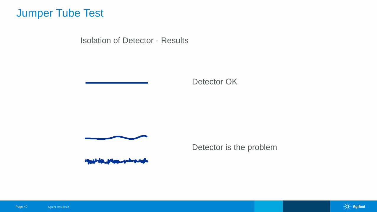
Jumper Tube Test
Isolation of Detector - Results
Detector is the problem
Detector OK
Agilent Restricted
Page 41
Jumper Tube Test
Isolate the Injector
• Connect the injector and detector
- 1-2 meters deactivated fused silica tubing
• Turn on carrier gas
• Blank run
Agilent Restricted
Page 42
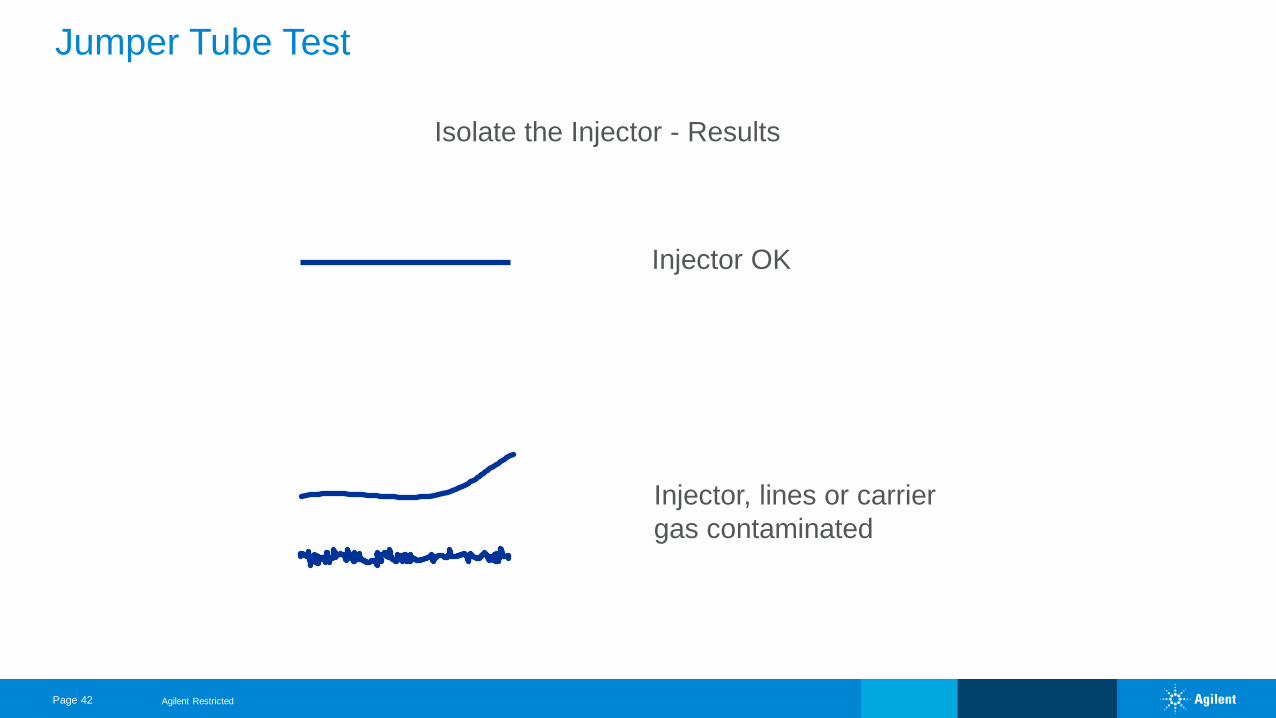
Jumper Tube Test
Isolate the Injector - Results
Injector OK
Injector, lines or carrier
gas contaminated
Agilent Restricted
Page 43
Jumper Tube Test
Isolate the Column
• Re-install the column
• Set up as before
• Blank run
Agilent Restricted
Page 44
Jumper Tube Test
Isolate the Column - Results
• Problem returns: it’s the column
• Problem gone: previous leak, solid debris, or installation
problem
Agilent Restricted
Page 45
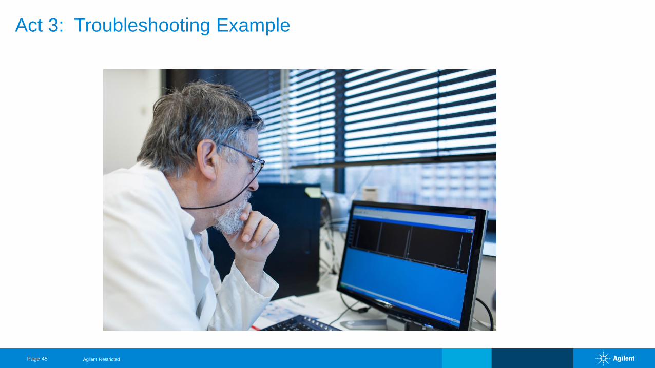
Act 3: Troubleshooting Example
Agilent Restricted
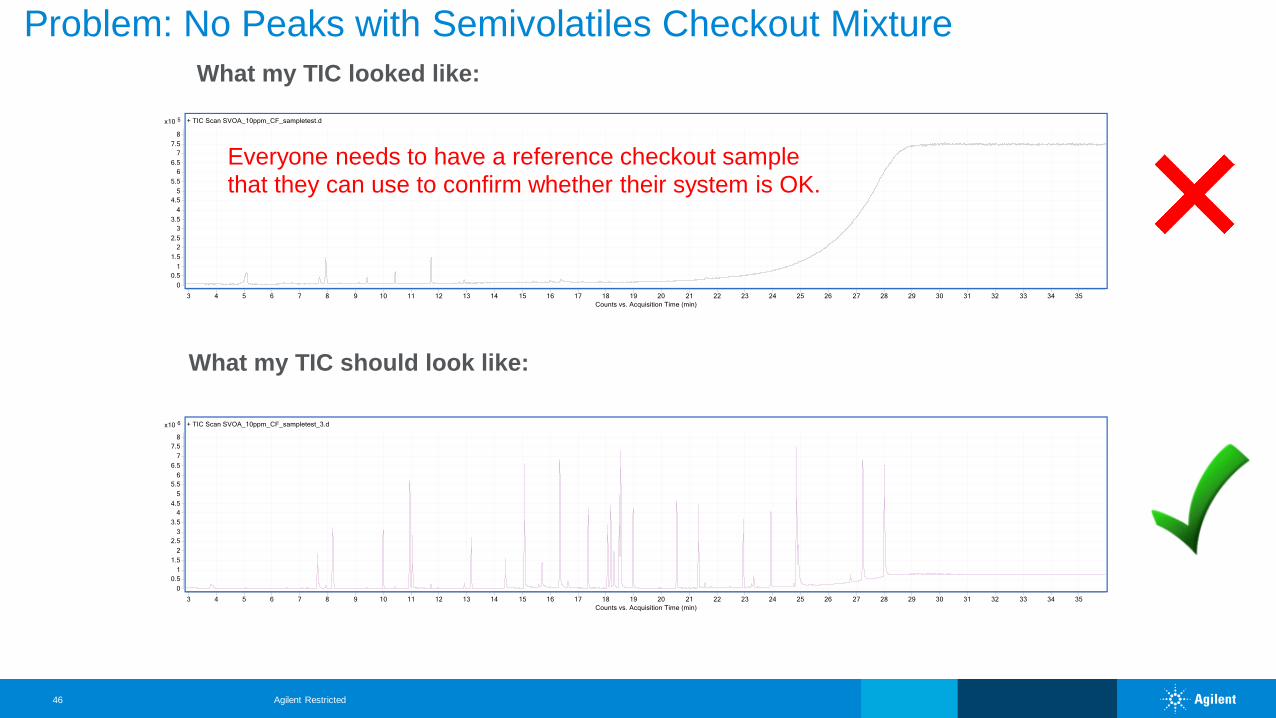
What my TIC should look like:
What my TIC looked like:
Everyone needs to have a reference checkout samplethat they can use to confirm whether their system is OK.
Problem: No Peaks with Semivolatiles Checkout Mixture
Agilent Restricted46
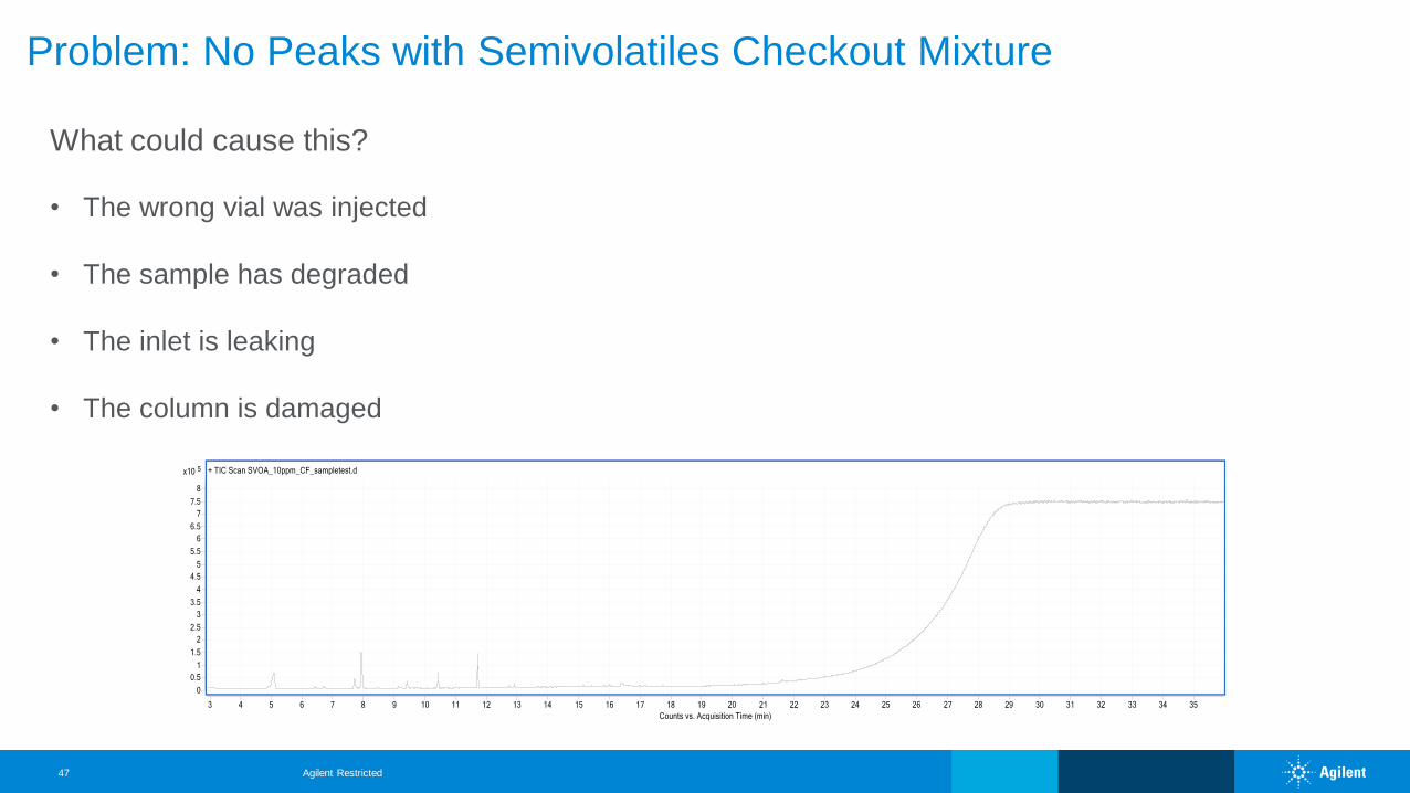
Problem: No Peaks with Semivolatiles Checkout Mixture
What could cause this?
• The wrong vial was injected
• The sample has degraded
• The inlet is leaking
• The column is damaged
Agilent Restricted47
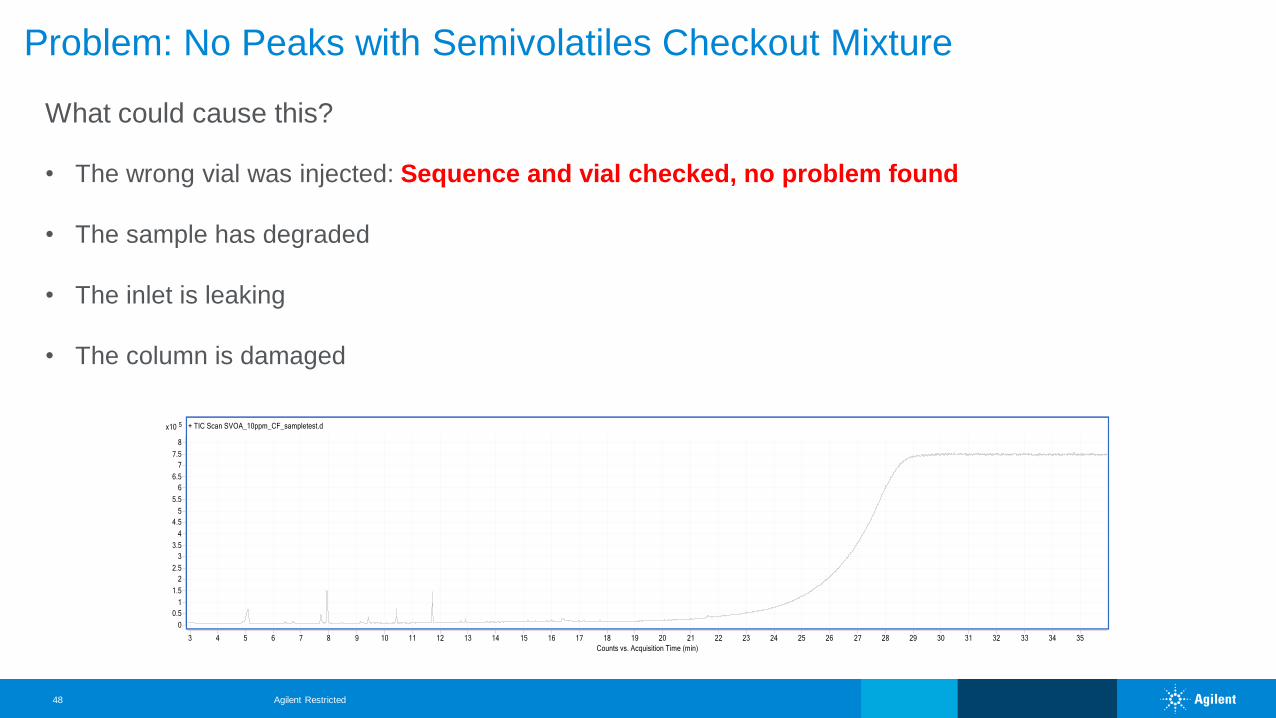
Problem: No Peaks with Semivolatiles Checkout Mixture
What could cause this?
• The wrong vial was injected: Sequence and vial checked, no problem found
• The sample has degraded
• The inlet is leaking
• The column is damaged
Agilent Restricted48
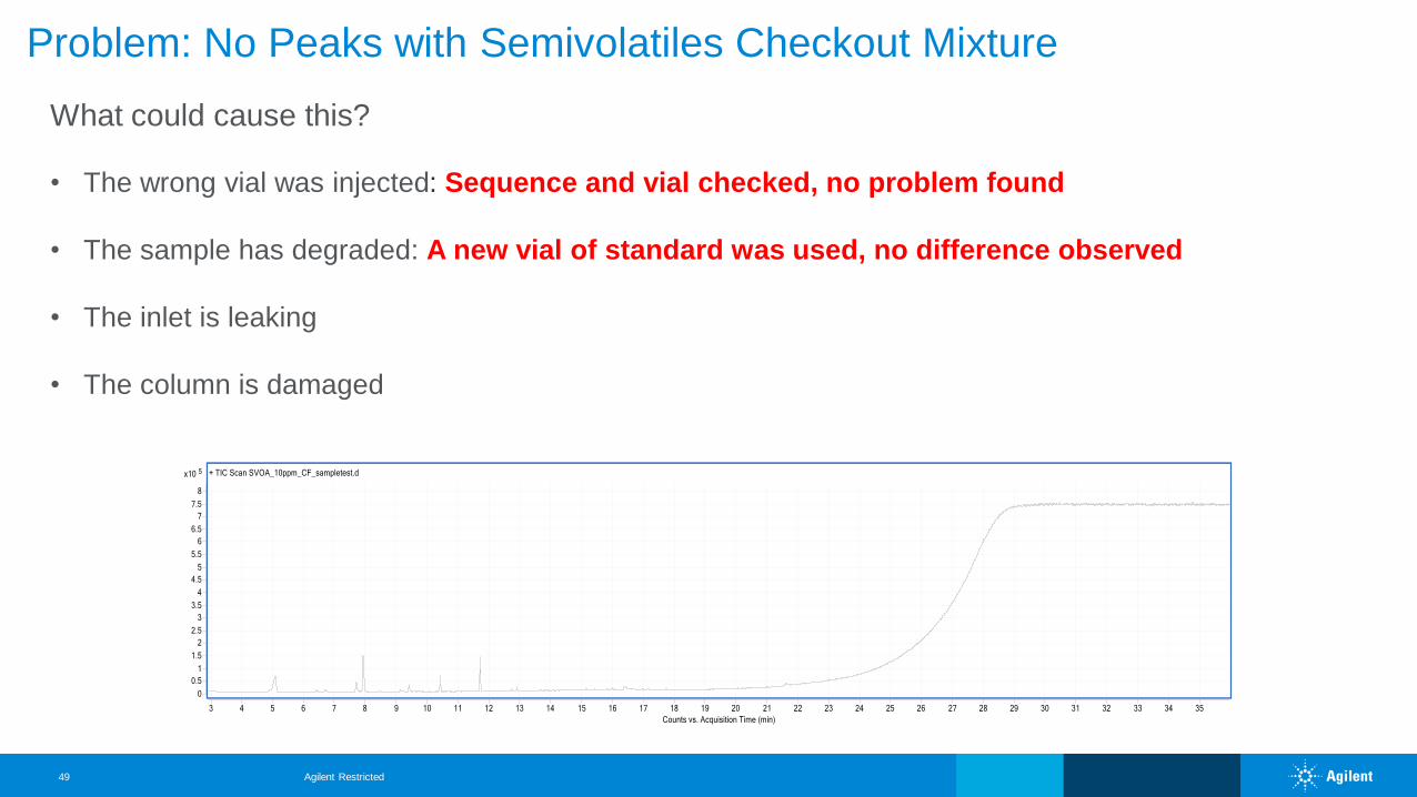
Problem: No Peaks with Semivolatiles Checkout Mixture
What could cause this?
• The wrong vial was injected: Sequence and vial checked, no problem found
• The sample has degraded: A new vial of standard was used, no difference observed
• The inlet is leaking
• The column is damaged
Agilent Restricted49
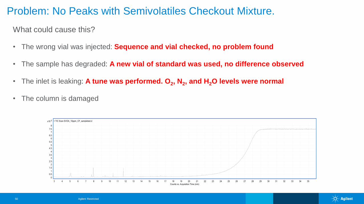
Problem: No Peaks with Semivolatiles Checkout Mixture.
What could cause this?
• The wrong vial was injected: Sequence and vial checked, no problem found
• The sample has degraded: A new vial of standard was used, no difference observed
• The inlet is leaking: A tune was performed. O2, N2, and H2O levels were normal
• The column is damaged
Agilent Restricted50
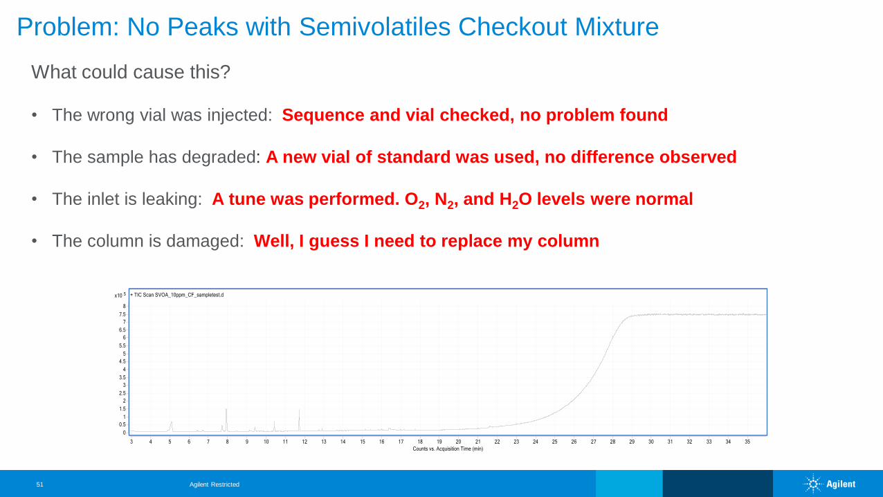
Problem: No Peaks with Semivolatiles Checkout Mixture
What could cause this?
• The wrong vial was injected: Sequence and vial checked, no problem found
• The sample has degraded: A new vial of standard was used, no difference observed
• The inlet is leaking: A tune was performed. O2, N2, and H2O levels were normal
• The column is damaged: Well, I guess I need to replace my column
Agilent Restricted51
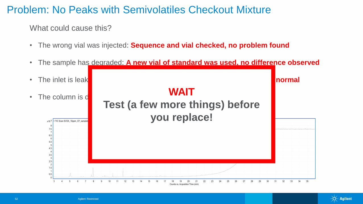
What could cause this?
• The wrong vial was injected: Sequence and vial checked, no problem found
• The sample has degraded: A new vial of standard was used, no difference observed
• The inlet is leaking: A tune was performed. O2, N2, and H2O levels were normal
• The column is damaged: Well, I guess I need to replace my column
Problem: No Peaks with Semivolatiles Checkout Mixture
WAIT
Test (a few more things) before
you replace!
Agilent Restricted52
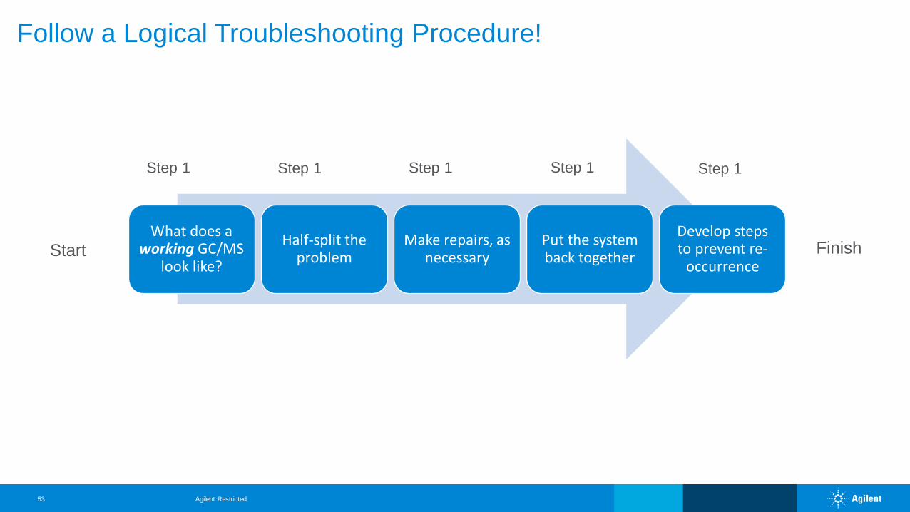
What does a working GC/MS
look like?
Half-split the problem
Make repairs, as necessary
Put the system back together
Develop steps to prevent re-
occurrence
Follow a Logical Troubleshooting Procedure!
Start Finish
Step 1 Step 1 Step 1 Step 1 Step 1
Agilent Restricted53
What does a working GC/MS look like?
Half-split the problemMake repairs, as
necessaryPut the system back
togetherDevelop steps to
prevent re-occurrence
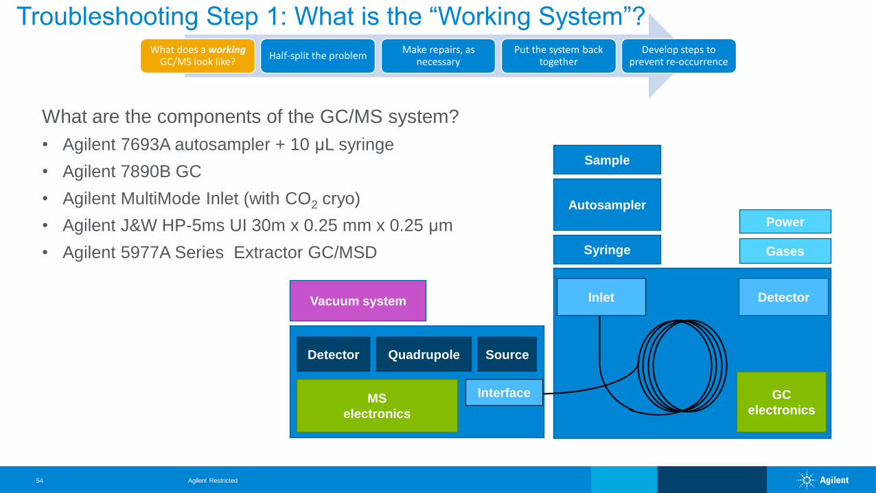
Troubleshooting Step 1: What is the “Working System”?
What are the components of the GC/MS system?
• Agilent 7693A autosampler + 10 μL syringe
• Agilent 7890B GC
• Agilent MultiMode Inlet (with CO2 cryo)
• Agilent J&W HP-5ms UI 30m x 0.25 mm x 0.25 μm
• Agilent 5977A Series Extractor GC/MSD
GC
electronics
Autosampler
Vacuum system Detector
Power
Gases
Inlet
Interface
Syringe
SourceQuadrupoleDetector
MS
electronics
Sample
Agilent Restricted54
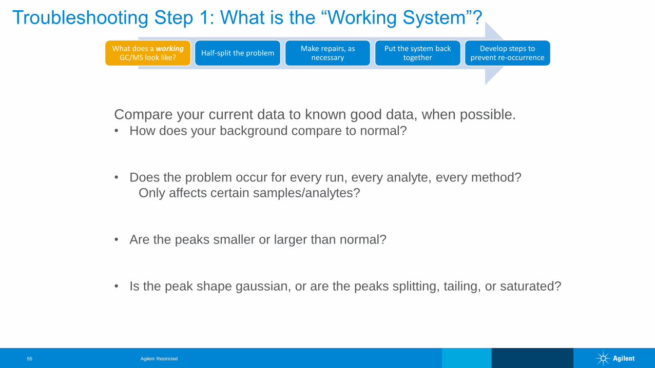
Compare your current data to known good data, when possible. • How does your background compare to normal?
• Does the problem occur for every run, every analyte, every method?
Only affects certain samples/analytes?
• Are the peaks smaller or larger than normal?
• Is the peak shape gaussian, or are the peaks splitting, tailing, or saturated?
Troubleshooting Step 1: What is the “Working System”?
What does a working GC/MS look like?
Half-split the problemMake repairs, as
necessaryPut the system back
togetherDevelop steps to
prevent re-occurrence
Agilent Restricted55
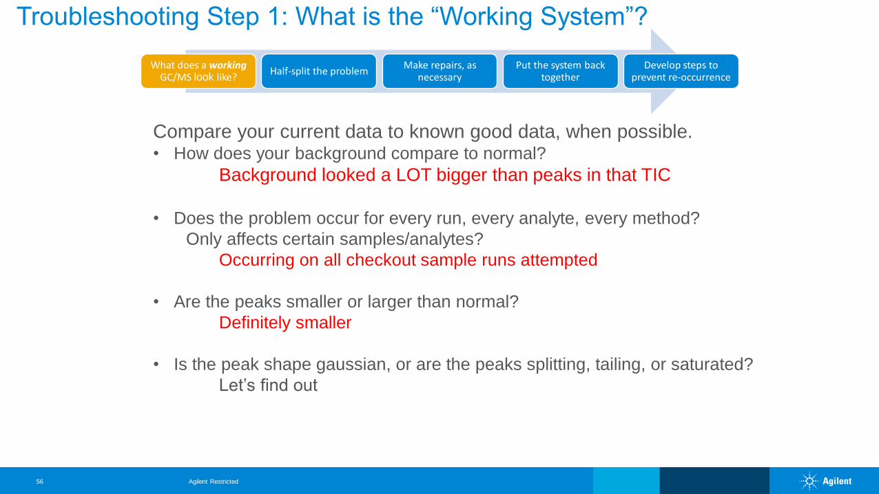
Compare your current data to known good data, when possible. • How does your background compare to normal?
Background looked a LOT bigger than peaks in that TIC
• Does the problem occur for every run, every analyte, every method?
Only affects certain samples/analytes?
Occurring on all checkout sample runs attempted
• Are the peaks smaller or larger than normal?
Definitely smaller
• Is the peak shape gaussian, or are the peaks splitting, tailing, or saturated?
Let’s find out
Troubleshooting Step 1: What is the “Working System”?
What does a working GC/MS look like?
Half-split the problemMake repairs, as
necessaryPut the system back
togetherDevelop steps to
prevent re-occurrence
Agilent Restricted56
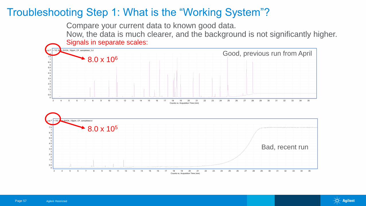
Good, previous run from April
Bad, recent run
Compare your current data to known good data. Now, the data is much clearer, and the background is not significantly higher. Signals in separate scales:
8.0 x 10⁵
8.0 x 10⁶
Troubleshooting Step 1: What is the “Working System”?
Page 57 Agilent Restricted
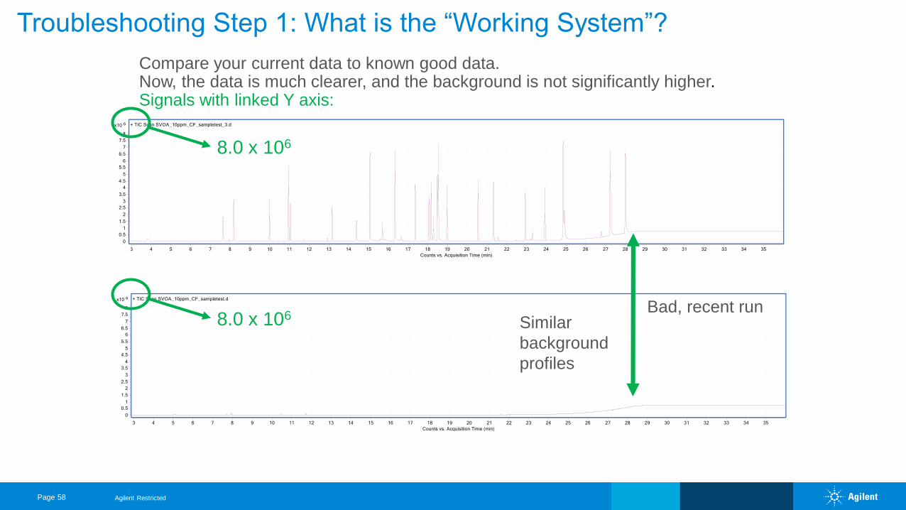
Compare your current data to known good data. Now, the data is much clearer, and the background is not significantly higher. Signals with linked Y axis:
Similar
background
profiles
Good, previous run from April
Bad, recent run
8.0 x 10⁶
8.0 x 10⁶
Troubleshooting Step 1: What is the “Working System”?
Page 58 Agilent Restricted
What does a working GC/MS look like?
Half-split the problemMake repairs, as
necessaryPut the system back
togetherDevelop steps to
prevent re-occurrence
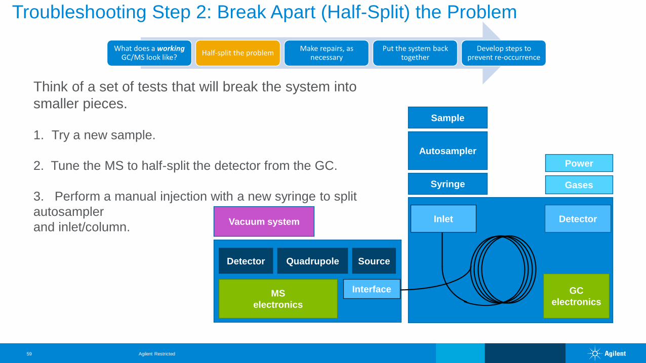
Troubleshooting Step 2: Break Apart (Half-Split) the Problem
GC
electronics
Autosampler
Vacuum system Detector
Power
Gases
Inlet
Interface
Syringe
SourceQuadrupoleDetector
MS
electronics
Sample
Think of a set of tests that will break the system into
smaller pieces.
1. Try a new sample.
2. Tune the MS to half-split the detector from the GC.
3. Perform a manual injection with a new syringe to split
autosampler
and inlet/column.
Agilent Restricted59
What does a working GC/MS look like?
Half-split the problemMake repairs, as
necessaryPut the system back
togetherDevelop steps to
prevent re-occurrence
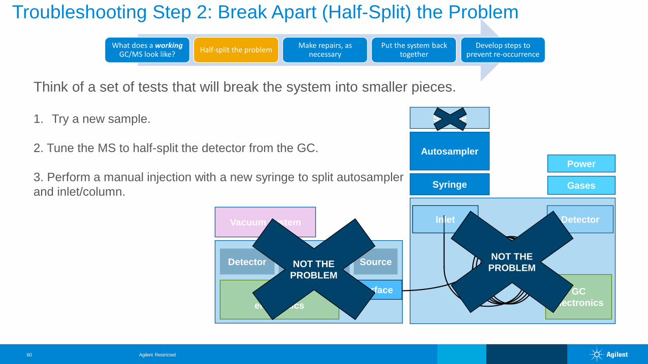
Troubleshooting Step 2: Break Apart (Half-Split) the Problem
GC
electronics
Autosampler
Vacuum system Detector
Power
Gases
Inlet
Interface
Syringe
SourceQuadrupoleDetector
MS
electronics
Sample
NOT THE
PROBLEM
NOT THE
PROBLEM
Think of a set of tests that will break the system into smaller pieces.
1. Try a new sample.
2. Tune the MS to half-split the detector from the GC.
3. Perform a manual injection with a new syringe to split autosampler
and inlet/column.
Agilent Restricted60
What does a working GC/MS look like?
Half-split the problemMake repairs, as
necessaryPut the system back
togetherDevelop steps to
prevent re-occurrence
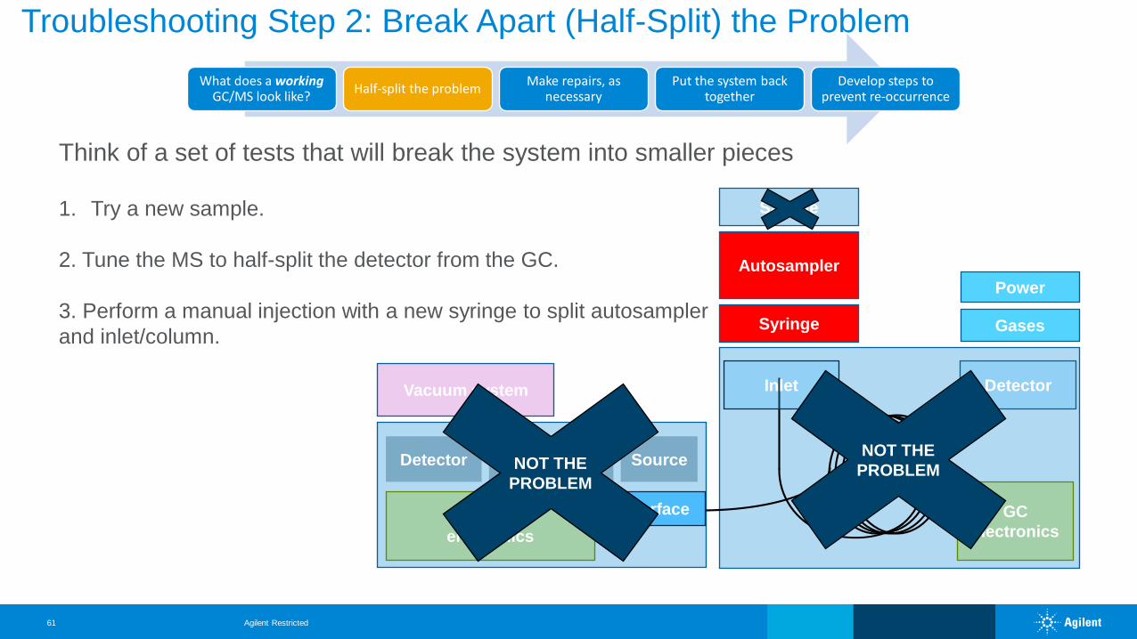
Troubleshooting Step 2: Break Apart (Half-Split) the Problem
GC
electronics
Autosampler
Vacuum system Detector
Power
Gases
Inlet
Interface
Syringe
SourceQuadrupoleDetector
MS
electronics
Sample
NOT THE
PROBLEM
NOT THE
PROBLEM
Think of a set of tests that will break the system into smaller pieces
1. Try a new sample.
2. Tune the MS to half-split the detector from the GC.
3. Perform a manual injection with a new syringe to split autosampler
and inlet/column.
Agilent Restricted61
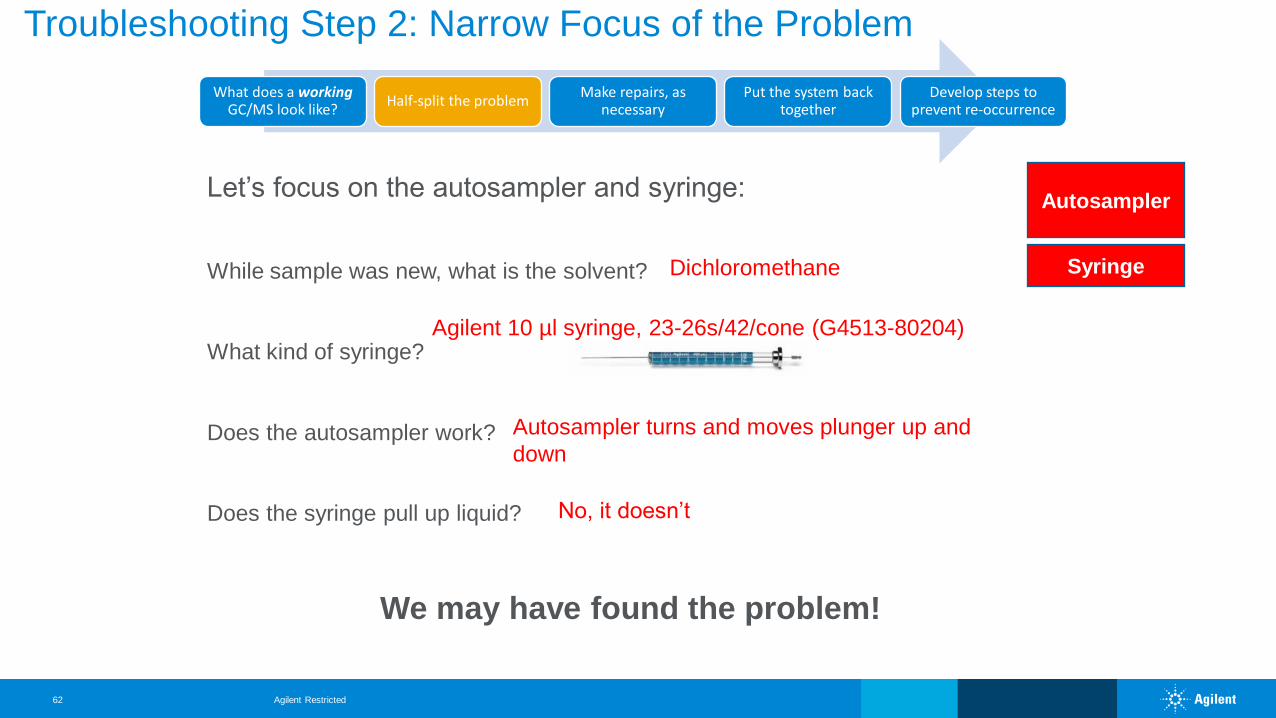
Let’s focus on the autosampler and syringe:
While sample was new, what is the solvent?
What kind of syringe?
Does the autosampler work?
Does the syringe pull up liquid?
Autosampler
SyringeDichloromethane
Agilent 10 µl syringe, 23-26s/42/cone (G4513-80204)
Autosampler turns and moves plunger up and
down
No, it doesn’t
We may have found the problem!
What does a working GC/MS look like?
Half-split the problemMake repairs, as
necessaryPut the system back
togetherDevelop steps to
prevent re-occurrence
Troubleshooting Step 2: Narrow Focus of the Problem
Agilent Restricted62
What does a working GC/MS look like?
Half-split the problemMake repairs, as
necessaryPut the system back
togetherDevelop steps to
prevent re-occurrence
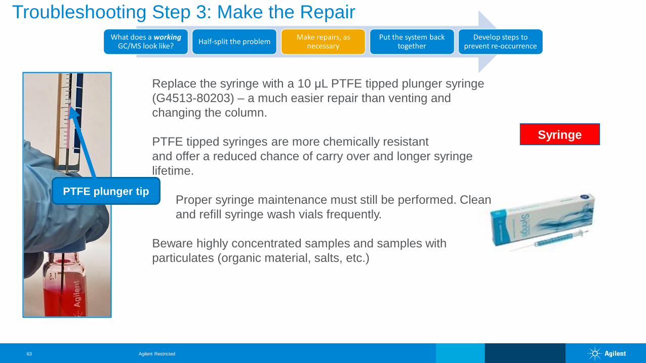
Syringe
Troubleshooting Step 3: Make the Repair
Replace the syringe with a 10 μL PTFE tipped plunger syringe
(G4513-80203) – a much easier repair than venting and
changing the column.
PTFE tipped syringes are more chemically resistant
and offer a reduced chance of carry over and longer syringe
lifetime.
Proper syringe maintenance must still be performed. Clean
and refill syringe wash vials frequently.
Beware highly concentrated samples and samples with
particulates (organic material, salts, etc.)
PTFE plunger tip
Agilent Restricted63
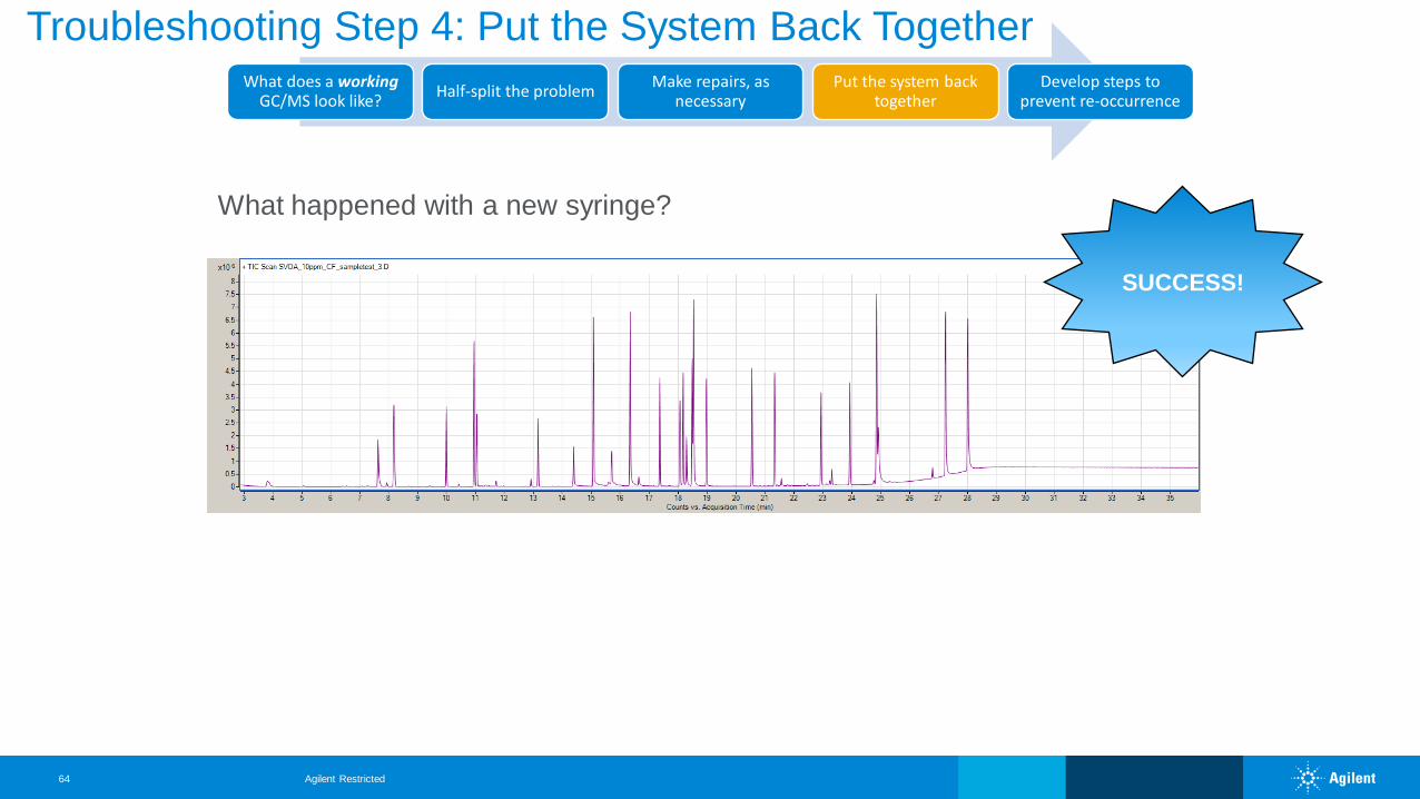
SUCCESS!
What happened with a new syringe?
What does a working GC/MS look like?
Half-split the problemMake repairs, as
necessaryPut the system back
togetherDevelop steps to
prevent re-occurrence
Troubleshooting Step 4: Put the System Back Together
Agilent Restricted64

Agilent Restricted65
Have a Good Troubleshooting Story?- Let Us Know!
Please call or email us today to share a
troubleshooting success story or if you
need help troubleshooting!
Page 66
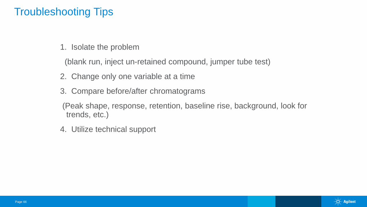
Troubleshooting Tips
1. Isolate the problem
(blank run, inject un-retained compound, jumper tube test)
2. Change only one variable at a time
3. Compare before/after chromatograms
(Peak shape, response, retention, baseline rise, background, look for trends, etc.)
4. Utilize technical support
Page 67
Remember
Multiple cause and effect
Do not change too many variables at once
Complete system = Carrier Gas + Injector +
Column + Detector + Data System
Contact Agilent Chemistries and Supplies Technical Support
1-800-227-9770 Option 3, Option 3:
Option 1 for GC/GC/MS Columns and Supplies
Option 2 for LC/LC/MS Columns and Supplies
Option 3 for Sample Preparation, Filtration and QuEChERS
Option 4 for Spectroscopy Supplies
Available in the USA 8-5 all time zones
Page 68