
A Survey of Millimeter-Wave Communication: Physical-Layer ...
37
1 A Survey of Millimeter-Wave Communication: Physical-Layer Technology Specifications and Enabling Transmission Technologies Shiwen He * , Member, IEEE, Yan Zhang * , Member, IEEE, Jiaheng Wang * , Senior Member, IEEE, Jian Zhang, Member, IEEE, Ju Ren, Member, IEEE, Yaoxue Zhang, Senior Member, IEEE, Weihua Zhuang, Fellow, IEEE, and Xuemin (Sherman) Shen, Fellow, IEEE Abstract—In recent years, millimeter-wave (mmWave) fre- quency bands, which offer abundant underutilized spectral resources, have been explored and exploited to meet the re- quirements of emerging wireless services highlighted by high data rates, ultra-reliability and ultra-low delivery latency. Yet, the unique characteristics of mmWave, e.g., continuous wide bandwidth, large path and penetration losses, along with hard- ware constraints, call for innovative technologies for mmWave communication. In the last few years, an extensive amount of work on mmWave communication has been carried out by the researchers and practitioners from both academia and industry, and various technologies were developed for mmWave communication systems to fulfill the full potential of mmWave frequency bands. This paper provides a comprehensive survey of the standardization of mmWave communication, the latest progress and outcomes of the research on mmWave communi- cation technologies, and the emerging applications of mmWave communication. In particular, we provide a timely and in-depth summary of the state-of-art technology specifications of mmWave communication with a focus on the physical layer. Then, we elaborate a number of well-established or promising antenna architectures in mmWave communication systems and investigate the enabling physical layer transmission technologies. Finally, we present the existing and emerging applications of mmWave communication and discuss the potential research issues. Index Terms—Millimeter-wave communication, technology specification, antenna architecture, transceiver design, hardware impairment. I. I NTRODUCTION According to Ericsson’s mobility report, worldwide mobile subscriptions will increase to 8.9 billion, cellular Internet of Things (IoT) connections will reach 3.5 billion, and worldwide * The authors Shiwen He, Yan Zhang, and JiahengWang contribute equally. Manuscript received Nov. 22, 2020; revised Apr. 03, 2021; Jun. 07, 2021; accepted Jun. 13, 2021. This work was supported by National Natural Science Foundation of China under Grants 62171474 and 61971132, the Natural Science Foundation of Hunan Province under Grants 2020JJ4745; the National Natural Science Foundation of China under Grant 61720106003. (Corresponding author: Jian Zhang) Shiwen He, Jian Zhang, Ju Ren, and Yaoxue Zhang are with the School of Computer Science and Engineering, Central South University, Changsha 410083, China. Shiwen He is also with the Purple Mountain Laboratories, Nanjing 210096, China. (email: {shiwen.he.hn, jianzhang, renju}@csu.edu.cn, [email protected]). Yan Zhang and Jiaheng Wang are with the School of Information Sci- ence and Engineering, Southeast University, Nanjing 210096, China. (email: {yanzhang ise, jhwang}@seu.edu.cn). Weihua Zhuang and Xuemin (Sherman) Shen are with the Department of Electrical and Computer Engineering, University of Waterloo, ON, Canada N2L 3G1. (email: {wzhuang, sshen}@uwaterloo.ca). total monthly mobile data traffic will reach 107 exabytes by 2023 [1]. The proliferation of various smart devices and the popularity of mobile Internet services, as illustrated in Fig. 1, have significantly stimulated the demands for wireless communication with multi-gigabits per second (Gbps) peak throughputs, tens of megabits per second (Mbps) cell edge rates, ultra-reliable delivery, and end-to-end latency at the order of 1 ms. These emerging demands not only bring chal- lenges to the design of wireless network architecture, but also drive the existing communication systems to evolve toward higher frequency bands [2]. Developing wireless communica- tion technologies that have the ability to support high data rates in ultra-dense networks has drawn considerable attention from both academia and industry. Millimeter-wave (mmWave) com- munication, with abundant underutilized spectral resources, provides a promising solution to satisfy the aforementioned demands in the beyond fifth generation (5G) and 6G wireless communication systems. However, a great deal of research is still required to enable mmWaves for mobile users including hardware and algorithms to overcome the large path-loss and penetration loss. This survey focuses on discussing the state- of-art and the development trends of mmWave communication. A. Brief Introduction of mmWave The very limited spectral resources in microwave frequency bands are insufficient to satisfy the demands of explosive data traffic and high data rate (up to 10 Gbps). Consequently, exploiting the vast amount of unused spectrum in high fre- quency bands in 5G/6G mobile communication systems has recently gained significant interests from both academia and industry. In particular, mmWave communication operating at the frequency range 30 to 300 Gigahertz (GHz) has emerged as a new frontier to realize extremely high rate transmission. Fortunately, the recent advancements of mmWave integrated chips pave the foundation for Gbps wireless transmission operating at beyond sub-6 GHz frequency bands. The research and development (R&D) on mmWave devices and technolo- gies have facilitated understanding the propagation character- istics of mmWave, establishing technology specifications for mmWave communication and designing efficient transceivers with acceptable cost and implementation complexity [3]. Until recently, the researchers begin to pay a lot of attention to mmWave cellular communication network. In practice, a large
Transcript of A Survey of Millimeter-Wave Communication: Physical-Layer ...

1
A Survey of Millimeter-Wave Communication:Physical-Layer Technology Specifications and
Enabling Transmission TechnologiesShiwen He∗, Member, IEEE, Yan Zhang∗, Member, IEEE, Jiaheng Wang∗, Senior Member, IEEE,
Jian Zhang, Member, IEEE, Ju Ren, Member, IEEE, Yaoxue Zhang, Senior Member, IEEE,Weihua Zhuang, Fellow, IEEE, and Xuemin (Sherman) Shen, Fellow, IEEE
Abstract—In recent years, millimeter-wave (mmWave) fre-quency bands, which offer abundant underutilized spectralresources, have been explored and exploited to meet the re-quirements of emerging wireless services highlighted by highdata rates, ultra-reliability and ultra-low delivery latency. Yet,the unique characteristics of mmWave, e.g., continuous widebandwidth, large path and penetration losses, along with hard-ware constraints, call for innovative technologies for mmWavecommunication. In the last few years, an extensive amountof work on mmWave communication has been carried outby the researchers and practitioners from both academia andindustry, and various technologies were developed for mmWavecommunication systems to fulfill the full potential of mmWavefrequency bands. This paper provides a comprehensive surveyof the standardization of mmWave communication, the latestprogress and outcomes of the research on mmWave communi-cation technologies, and the emerging applications of mmWavecommunication. In particular, we provide a timely and in-depthsummary of the state-of-art technology specifications of mmWavecommunication with a focus on the physical layer. Then, weelaborate a number of well-established or promising antennaarchitectures in mmWave communication systems and investigatethe enabling physical layer transmission technologies. Finally,we present the existing and emerging applications of mmWavecommunication and discuss the potential research issues.
Index Terms—Millimeter-wave communication, technologyspecification, antenna architecture, transceiver design, hardwareimpairment.
I. INTRODUCTION
According to Ericsson’s mobility report, worldwide mobilesubscriptions will increase to 8.9 billion, cellular Internet ofThings (IoT) connections will reach 3.5 billion, and worldwide
∗ The authors Shiwen He, Yan Zhang, and JiahengWang contribute equally.Manuscript received Nov. 22, 2020; revised Apr. 03, 2021; Jun. 07, 2021;
accepted Jun. 13, 2021. This work was supported by National NaturalScience Foundation of China under Grants 62171474 and 61971132, theNatural Science Foundation of Hunan Province under Grants 2020JJ4745;the National Natural Science Foundation of China under Grant 61720106003.(Corresponding author: Jian Zhang)
Shiwen He, Jian Zhang, Ju Ren, and Yaoxue Zhang are with the Schoolof Computer Science and Engineering, Central South University, Changsha410083, China. Shiwen He is also with the Purple Mountain Laboratories,Nanjing 210096, China. (email: {shiwen.he.hn, jianzhang, renju}@csu.edu.cn,[email protected]).
Yan Zhang and Jiaheng Wang are with the School of Information Sci-ence and Engineering, Southeast University, Nanjing 210096, China. (email:{yanzhang ise, jhwang}@seu.edu.cn).
Weihua Zhuang and Xuemin (Sherman) Shen are with the Department ofElectrical and Computer Engineering, University of Waterloo, ON, CanadaN2L 3G1. (email: {wzhuang, sshen}@uwaterloo.ca).
total monthly mobile data traffic will reach 107 exabytesby 2023 [1]. The proliferation of various smart devices andthe popularity of mobile Internet services, as illustrated inFig. 1, have significantly stimulated the demands for wirelesscommunication with multi-gigabits per second (Gbps) peakthroughputs, tens of megabits per second (Mbps) cell edgerates, ultra-reliable delivery, and end-to-end latency at theorder of 1 ms. These emerging demands not only bring chal-lenges to the design of wireless network architecture, but alsodrive the existing communication systems to evolve towardhigher frequency bands [2]. Developing wireless communica-tion technologies that have the ability to support high data ratesin ultra-dense networks has drawn considerable attention fromboth academia and industry. Millimeter-wave (mmWave) com-munication, with abundant underutilized spectral resources,provides a promising solution to satisfy the aforementioneddemands in the beyond fifth generation (5G) and 6G wirelesscommunication systems. However, a great deal of research isstill required to enable mmWaves for mobile users includinghardware and algorithms to overcome the large path-loss andpenetration loss. This survey focuses on discussing the state-of-art and the development trends of mmWave communication.
A. Brief Introduction of mmWave
The very limited spectral resources in microwave frequencybands are insufficient to satisfy the demands of explosive datatraffic and high data rate (up to 10 Gbps). Consequently,exploiting the vast amount of unused spectrum in high fre-quency bands in 5G/6G mobile communication systems hasrecently gained significant interests from both academia andindustry. In particular, mmWave communication operating atthe frequency range 30 to 300 Gigahertz (GHz) has emergedas a new frontier to realize extremely high rate transmission.Fortunately, the recent advancements of mmWave integratedchips pave the foundation for Gbps wireless transmissionoperating at beyond sub-6 GHz frequency bands. The researchand development (R&D) on mmWave devices and technolo-gies have facilitated understanding the propagation character-istics of mmWave, establishing technology specifications formmWave communication and designing efficient transceiverswith acceptable cost and implementation complexity [3]. Untilrecently, the researchers begin to pay a lot of attention tommWave cellular communication network. In practice, a large

2
Vehicular communication
Intelligenttransportation
Flying eBS control
Handover
SCeBS
Mobility management
D2D communication
Computation offloading
MECserver
Mobile edge computing
V2X
V2V
RSU
BBU
Cloud RAN
RRH
eRRH
Machine type communication (IoT)
Interference management
Big data
Intelligentindustry
Intelligent office
HetNets
UAV communication
Spectrum sharing
Smart home
Autonomous vehicles
Neighborhood scanning
Fig. 1. An illustration of future communication networks.
number of mmWave frequency bands have not been used inpractical wireless communication systems. For example, someunderutilized mmWave frequency bands include [4]:
• 28 GHz/38 GHz licensed but underutilized: 3.4 GHzbandwidth available in total;
• 57 GHz to 64 GHz unlicensed: 7 GHz bandwidth avail-able in total;
• 71/81/92 GHz light-licensed band: 12.9 GHz bandwidthavailable in total.
In contrast with the increasingly crowded microwave fre-quency bands, there are abundant spectrum resources inmmWave frequency bands possibly available for wirelesscommunication, for example 5 GHz continuous bandwidth atabove 57 GHz. It means that an extremely high data rate (10+Gbps) can be achieved using simple modulation schemes, suchas quadrature phase shift keying (QPSK). Yet, to harvest thefull benefits of mmWave communications in practice, there aremany technical challenges that require novel design principlesand breakthrough technologies [5].
B. Brief Introduction of Hybrid ArchitectureIt is widely known that, at mmWave frequency bands,
electromagnetic waves suffer from severe path and blockagelosses, which significantly degrade communication perfor-mance. An effective approach is to adopt large-scale antenna
arrays to compensate for the performance loss. Fortunately,packing a large number of antenna elements at transceiverand adopting directional transmission can be easily imple-mented in mmWave communication systems. Large arrayscomprised of many antenna elements is a preferable choicefor obtaining beamforming gain to overcome path-loss andestablish links with reasonable signal-to-noise ratio. Further-more, spatial multiplexing may be used to improve the spectralefficiency via using large arrays. However, signal processingin mmWave systems is subject to a set of non-trivial practicalconstraints [16]. For example, in the conventional multiple-input multiple-output (MIMO) communication systems, eachantenna requires a dedicated baseband and radio frequency(RF) chain, which facilitate digitally controlling the phase andamplitude of the baseband signal. However, both the hardwarecost and the power consumption increase with the numbers ofthe antennas and RF chains, as well as carrier frequencies.Hence, it is difficult to provide an RF chain for each antennaand perform all signal processing in the baseband digitally inmmWave communication systems. This motivates us to devel-op new transceiver architectures and to analyze their impact onMIMO signal processing, including precoding/combining andchannel estimation. How to balance the system performance,hardware cost, and power consumption becomes a key pointfor mmWave communication systems.

3
TABLE I. Comparison and summary of related surveys on mmWave communication.Discussion on Technical Specifications of mmWave Discussion on enabling PHY-layer transmission technologies
WirelessHD 802.15.3 802.11 Cellular AntennaArchitecture
Channelmodel
Channelestimation
Beam-forming
Hardwareimpairments
Wave-form
Networklayer
Use case Ref. YoPc d ad aj ay
X [6] 2017X X X [7] 2018
X [8] 2018X [9] 2020
X X X WB, SM, CA [10] 2015X X X GC [11] 2016X X X X [12] 2018
X X X X X PA, PN X XWD, VR, VN,
SaC, 5G [13] 2018
X X X X X ADCs X [14] 2017X X [15] 2017
X X X X X ADCs [16] 2016
X X X X XHealth andsafety issue [17] 2018
X X X X [18] 2018X X [19] 2020X X X X [20] 2021X X X X UAVs [21] 2018
X X X X [22] 2018X [23] 2017X [24] 2019
X X X X X X X X X X XPA,ADCs,DACs,I/Q,PSs, PN
Ultra-dense, UAV, GC,Physical security,Content-centric,
Sensing and Imaging,intelligent communication,
· · ·
This survey
An alternative approach, aiming to reduce the number ofRF chains and to alleviate the hardware implementation costand computational complexity, is the digital-analog hybridantenna array architecture for mmWave communication sys-tems. In this architecture, transceivers have the ability to applyhigh-dimensional (tall) RF precoders/combiner, implementedvia analog phase shifter (PS) networks, followed by low-dimensional (small) digital precoder/combiner implementedat baseband. In the existing research, fully connected andpartially connected structures are the two most commonlyused digital-analog hybrid antenna array architectures. In theformer, each RF chain is connected to all antennas, whilein the latter only a subset of antennas connects with eachRF chain. From the design perspective, fully connected ar-chitecture has the ability to obtain higher spectral efficiency,while partially connected architecture is expected to achievehigher energy efficiency. In addition, a variant of these twoarchitectures, i.e., dynamically connected architecture, has alsoattracted the attention of some researchers [25]. There arethree main difficulties for digital-analog hybrid antenna arrayarchitectures. Firstly, each element of an analog transceiveris constrained to constant modulus; Secondly, the cascade ofthe analog precoder/combiner and digital precoder/combinercomplicates the transceiver design; Thirdly, the number ofantennas is larger than that of RF chains, which makes it verydifficult to obtain sufficient information to directly estimate thechannel coefficients. Meanwhile, the directional transmissionrequires a large number of training overheads. To overcomethese difficulties, in recent years, the researchers from bothacademia and industry have done various studies on mmWavecommunication. In addition, many novel mmWave antennadesigns, such as the Lens antenna and fully digital antennaarchitecture, have been investigated extensively for mmWavecommunication systems.
C. Related Surveys of mmWave Communication
In this subsection, we review some existing surveys on theprogress of mmWave communication, as listed in Table I.The authors of [6] provide an overview of mmWave com-
munication for 5G wireless networks from the perspective ofpropagation models. They begin by describing an architectureof 5G wireless network, aiming to provide great flexibilityto support a myriad of Internet Protocol devices, small cellarchitecture, and dense coverage areas. After a brief intro-duction of propagation challenges of mmWave, they compar-atively summarize channel models including the line-of-sight(LoS) model, large-scale path-loss models, outdoor to indoor(O2I) penetration loss, and spatial consistency developed bythe various parties, such as the 3rd generation partnershipproject (3GPP) TR 38.901, 5G channel model (5GCM), mobileand wireless communications enablers for the twenty-twentyinformation society (METIS), mmWave based mobile radioaccess network for 5G integrated communications (mmMAG-IC) model, mmWave evolution for backhaul and access (Mi-WEBA) channel model, and quasi-deterministic radio channelgenerator (QuaDRiGa) model. Hemadeh et al. give a morecomprehensive summary of the propagation characteristicsof mmWave and further discuss the efforts and challengesof mmWave channel modeling [7]. To effectively exploitmmWave frequency bands for future wireless communication,they provide some constructive guidelines for the systemarchitecture and antenna design and further discuss the linkbudget analysis of mmWave networks. In [8], Wang et al. firstsummarize the requirements of the 5G channel modeling, andthen extensively review the progress of channel measurementsand models in recent years. Finally, they provide the future re-search directions for channel measurements and modeling. Theauthors of [9] review the-state-of-the-art in wave propagationand channel modeling by characterizing the wave propagationat chip-scales with different methods, and discuss in detail theworks on mmWave, Terahertz, and optical frequency bands.At the same time, they discuss the major challenges withthe characterization of wireless networks-on-chip channel andpotential solutions to address them. Their analysis show that,compared to microwave, mmWave possesses a high path-loss,penetration loss, and precipitation attenuation. To overcomethese shortcomings of mmWave and achieve performanceenhancement, directional transmission and (massive) MIMO

4
are two enabling techniques to simultaneously achieve thediversity, multiplexing, and beamforming gains for mmWavecommunication systems.
In [10], the authors first review the propagation characteris-tics of mmWave and the concept of basis service set of Instituteof Electrical and Electronics Engineers (IEEE) 802.11ad and802.15.3c1. They further discuss interference management andspatial reuse mechanisms, including time division multipleaccess, multi-hop concurrent transmission mechanism, carriersensing multiple access/collision avoidance, and frame baseddirective medium access control (MAC), taking into consid-eration the propagation characteristics of mmWave. The usecase of mmWave, e.g., small cell, device-to-device (D2D) incellular, and wireless backhaul (WB), are discussed. Finally,some open research issues including MIMO, full duplex, softdefined, control mechanism, heterogeneous network, and net-work state measurement, are pointed out for the research of fu-ture mmWave communication. Kutty et al. focus on discussingthe beamforming of three potential antenna architectures,i.e., analog antenna array, fully connected architecture, andpartially connected architecture [11]. Further, they describein detail the beam training procedure of 802.11ad and thecodebook design for mmWave communication systems. Someemerging research trends including mmWave MIMO beam-forming, multi-user concurrent beamforming, joint transmit-receive beamforming, hybrid beamforming, and beamformingfor green communication and security communication aresuggested for mmWave communication systems. By recallingthe directional multiple Gbps channel access and directionalmultiple Gbps beamforming mechanisms in 802.11ad, theauthors of [12] discuss the beam training procedure in detail,which may be used in the next generation of 802.11ad, i.e.,802.11ay, taking into account the channel bonding mecha-nism and multi-user mmWave communication. Note that thesurveys [11] and [12] mainly focus on the beam trainingprocedure based on codebook for mmWave communication.
Wang et al. provide a comprehensive survey from theperspective of taxonomy, research on physical (PHY)-layer,MAC-layer, network layer, cross layer optimization, use case,and available resources of mmWave communication [13]. Inparticular, about the research of PHY-layer, they first discussthe impact of nonlinear distortion of power amplifier (PA) andphase noise on mmWave communication systems, as well asthe development of reflector antennas, Lens antennas, hornantennas, mmWave microstrip antennas, on-chip antenna, andphased antennas. Then, the beamforming selection, precoding,channel model, new waveforms, and security of mmWavecommunication are discussed. Following that, the relatedprotocols of mmWave in ad hoc network, mesh network,WPAN, and cellular network are briefly discussed from theperspective of MAC-layer. They further summarize the relatedworks on the network layer, cross layer optimization, usecase, and the available resource of mmWave communication.For the application of mmWave in future mobile networks,Xiao et al. first discuss the key challenges and potentials,
1“IEEE” is omitted when referring to its wireless local area network(WLAN) and wireless personal area network (WPAN) standards.
such as large path-loss, abundant spectrum resource, andnarrow beam, of mmWave communication systems [14]. Then,they summarize the related channel measurement actives andbriefly introduce various channel models. They review theconcept of three potential MIMO antenna architectures, i.e.,fully connected architecture, partially connected architecture,and Lens antenna, and discuss the channel estimation basedon codebook and channel tracking, low resolution analog-to-digital (ADC) architecture, and the related progress in [14].Further, they discuss the multiple access technologies, e.g.,spatial division multiple access and non-orthogonal multipleaccess (NOMA), backhaul, coverage and connectivity topic-s for mmWave communication. Finally, the authors brieflydiscuss the standardization of mmWave frequency bands in3GPP from the viewpoint of use cases, mmWave and massiveMIMO, as well as hybrid beamforming architecture.
Three hybrid beamforming structures are categorized for thedownlink transmission at base station (BS) according to theconnection relation between RF chains and antennas [15]. Theauthors of [15] further point out the challenges encounteredin the design process of transceiver, such as the couplebetween the analog domain and digital domain, the constantmodulus on analog domain, and finite precision hardwareimplementation. To overcome these challenges, they discussthe design of hybrid precoding according to the instanta-neous or average channel state information (CSI) and thensuggest to adopt a dynamic hybrid structure to adapt to thechange of CSI to achieve the best performance of hybridbeamforming. Heath Jr., et al. provide an overview of signalprocessing challenges in mmWave wireless systems [16]. Theyfirst summarize the propagation characteristics of mmWaveand then discuss the antenna architectures, including antennaarray, (adaptive) hybrid antenna structure, and Lens antennastructure. Afterward, they focus on the design of precod-ing/combining and channel estimation based on dictionarycodebook by using the spatial-sparsity of mmWave and theorthogonal matching pursuit methods. In addition, they discussthe design of hybrid receiver with lower resolution ADCs,the beam training and sparse channel estimation in Lens-based continuous aperture phased MIMO transceivers. Busariet al. summarize the progress of mmWave communicationstarting with discussing the evolution of cellular networktechnologies, such as from MIMO to massive MIMO, multi-tier cellular heterogeneous networks, and the propagationcharacteristics of mmWave [17]. They further discuss theprogress of mmWave massive MIMO models, including theantenna architecture, precoding, channel estimation, channelmeasurement and modeling, as well as receiver processingtechniques. In addition, the authors summarize the cross-layerdesign considerations, such as waveform, access scheme, andfronthaul design. The authors of [18] summarize the researchprogress of hybrid beamforming technologies from the per-spective of the configuration of transceiver antenna and RFchains for mmWave communication. They further discuss themmWave heterogenous network and the resource managementincluding resource block allocation, beam management, medi-um access control, as well as initial search and tracking formmWave cellular communication. The work [19] summarizes
5
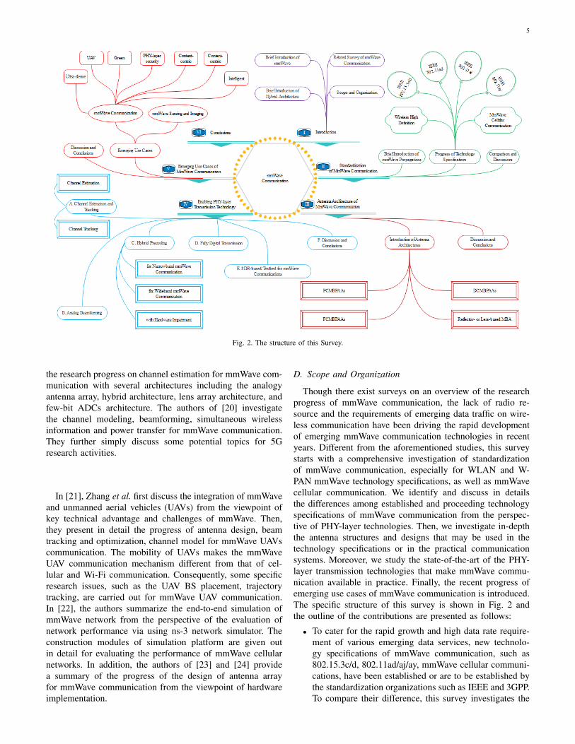
Fig. 2. The structure of this Survey.
the research progress on channel estimation for mmWave com-munication with several architectures including the analogyantenna array, hybrid architecture, lens array architecture, andfew-bit ADCs architecture. The authors of [20] investigatethe channel modeling, beamforming, simultaneous wirelessinformation and power transfer for mmWave communication.They further simply discuss some potential topics for 5Gresearch activities.
In [21], Zhang et al. first discuss the integration of mmWaveand unmanned aerial vehicles (UAVs) from the viewpoint ofkey technical advantage and challenges of mmWave. Then,they present in detail the progress of antenna design, beamtracking and optimization, channel model for mmWave UAVscommunication. The mobility of UAVs makes the mmWaveUAV communication mechanism different from that of cel-lular and Wi-Fi communication. Consequently, some specificresearch issues, such as the UAV BS placement, trajectorytracking, are carried out for mmWave UAV communication.In [22], the authors summarize the end-to-end simulation ofmmWave network from the perspective of the evaluation ofnetwork performance via using ns-3 network simulator. Theconstruction modules of simulation platform are given outin detail for evaluating the performance of mmWave cellularnetworks. In addition, the authors of [23] and [24] providea summary of the progress of the design of antenna arrayfor mmWave communication from the viewpoint of hardwareimplementation.
D. Scope and Organization
Though there exist surveys on an overview of the researchprogress of mmWave communication, the lack of radio re-source and the requirements of emerging data traffic on wire-less communication have been driving the rapid developmentof emerging mmWave communication technologies in recentyears. Different from the aforementioned studies, this surveystarts with a comprehensive investigation of standardizationof mmWave communication, especially for WLAN and W-PAN mmWave technology specifications, as well as mmWavecellular communication. We identify and discuss in detailsthe differences among established and proceeding technologyspecifications of mmWave communication from the perspec-tive of PHY-layer technologies. Then, we investigate in-depththe antenna structures and designs that may be used in thetechnology specifications or in the practical communicationsystems. Moreover, we study the state-of-the-art of the PHY-layer transmission technologies that make mmWave commu-nication available in practice. Finally, the recent progress ofemerging use cases of mmWave communication is introduced.The specific structure of this survey is shown in Fig. 2 andthe outline of the contributions are presented as follows:
• To cater for the rapid growth and high data rate require-ment of various emerging data services, new technolo-gy specifications of mmWave communication, such as802.15.3c/d, 802.11ad/aj/ay, mmWave cellular communi-cations, have been established or are to be established bythe standardization organizations such as IEEE and 3GPP.To compare their difference, this survey investigates the

6
TABLE II: Summary of Main Acronyms.Acronyms Definition Acronyms Definition
3GPP 3rd generation partnership project 5G Fifth generation5GCM 5G channel model ADC Analog digital converter
AS Angular spread APDP Average power delay profileAoA Angle of arrival AoD Angle of departureBS Base station BRP beam refinement phaseCA Cellular access CSI Channel state information
DAC Digital analog converter DS Delay spreadD2D Device-to-device FCMBPAAs Full connected MBPAASGHz Gigahertz Gbps Gigabits per secondGC Green communication HDMI High definition multimedia interface
HDTV High definition television HRRP High-rate PHYIoT Internet of things IEEE Institute of electrical and electronics engineersIF Inter-frequency ITU International telecommunication union
ITU-R ITU radio regulation LoS Line-of-sightLO Local oscillator LRP Low-rate PHY
mmWave Millimeter wave Mbps Megabits per secondMIMO Multiple-input multiple-output MBA Multibeam antenna
MBPAAs Multibeam phased array antennas MCS Modulation and coding schemeMRP Medium-rate PHY QAM Quadrature amplitude modulationO2I Outdoor to indoor O2O Outdoor to outdoor
OFDM Orthogonal frequency division multiplex PA Power amplifierPAR Project authorization request PAP Power azimuth profilePHY Physical PCMBPAAs Partially connected MBPAAsPN Phase noise PS Phase shifter
PSmC PHY security mmWave communication PPDU PHY-layer convergence procedure protocol data unitsPER Power elevation profile Ref. ReferenceRF Radio chain RMS Root-mean-square
RMS AS RMS angular spread RMa Rural macroSaC Satellite communication SC Single carrierSG Study group SM Small cell
SSW Sector level sweep SWIPT Simultaneous wireless information and power transferTG Task group UAV Unmanned aerial vehicles
ULA Uniform linear array UMi Urban microUMa Urban macro UPA Uniform panel arrayA/VR Augmented/virtual reality VN Vehicular networkWB Wireless backhaul WD Wearable devices
WLAN Wireless local area network WirelessHD Wireless high definitionWPAN Wireless personal area network Wi-Fi Wireless fidelityWRC World radio conference YoP Year of publication
PHY-layer transmission technologies of these technologyspecifications;
• This survey further analyzes several popular or potentialmmWave antenna architectures that are used or maybe used in the technology specifications or practicalmmWave communication systems or extensively appliedin the literature from the perspective of antenna design;
• This survey summarizes the latest study progress ofenabling PHY-layer transmission technologies includ-ing channel estimation and tracking, analog beamform-ing, hybrid precoding, and fully digital transmission formmWave communication with hybrid architecture andfully digital architecture;
• We also provide a summary of related researches inseveral emerging applications of mmWave communi-cation, including ultra-dense mmWave communication,UAV mmWave communication, green mmWave com-munication, PHY-layer security mmWave communication(PSmC), content-centric mmWave communication, andintelligent mmWave communication.
The remainder of this survey is organized as follows: Theprogress of technology specifications are described in SectionII.A few potential antenna array architectures are summarized
in Section III. The research progress of enabling PHY-layertransmission technologies is investigated in Section IV. SectionV discusses the research progress of several emerging applica-tions of mmWave communication. Conclusions are drawn inSection VI. A complete list of acronyms is given in Table II.
II. STANDARDIZATION OF MMWAVE COMMUNICATION
In future wireless communication networks, enhanced mo-bile broadband, massive machine type communication, andultra-reliable low-latency communication, are three major ap-plication scenarios. In these scenarios, high data rate (10+Gbps), ultra-reliable, and ultra-low latency are three keyperformance indices. For example, augmented/virtual reality(A/VR) applications require Gbps data rate, and typical emerg-ing Internet of things (IoT) applications require a latency from0.25 to 10 ms and an outage probability (or packet loss rate)in the order of 10−3 to 10−9 [26]. It is challenging for currentcommunication systems operating at sub-6 GHz frequencybands to satisfy these targets, due to the lack of radio resource.For example, the 802.11ac can only achieve the maximumtheoretical data rate 7 Gbps [27] and the 802.11ax under de-velopment has the ability to support the transmission rate withup to 10 Gbps [28]. But, in practice, it is difficult to realize

7
TABLE III. New WLAN usage models
Category Usage Model
Wireless display
• Desktop storage and display• Projection to television (TV)• Projector in conference room or auditorium• In-room gaming• Streaming from camcorder to display• Professional HDTV outside broadcast pickup
Distributionof HDTV
• Video streaming around the home• Intra-large-vehicle applications• Wireless networking for office• Remote medical assistance
Rapidupload&download
• Rapid file transfer/sync• Picture-by-picture viewing• Airplane docking (manifests, fuel, catering,· · · )• Downloading movie content to mobile device• Police surveillance data transfer
Backhaul • Multi-media mesh backhaul• Point-to-point backhaul
Outdoorcampus/auditorium
• Video demotele-presence in auditorium• Public safety mesh (incident presence)
Manufacturing floor • Automation
these theoretical peak data rates due to various communicationconstraints. To achieve higher data rates, wireless fidelity (Wi-Fi) alliance and IEEE standard organization have establisheda series of technology specifications for mmWave frequencybands, including wireless high definition (WirelessHD) [29],802.15.3c [30], 802.15.3d [31], 802.11ad [32], and 802.11a-j [33]. In addition, IEEE standard organization is establishinga new technology specification, i.e., 802.11ay, operating at60 GHz frequency band, to support higher data rates [34].The main usage cases of WirelessHD and 802.11ad/aj/ay arelisted in Table III [35]. Meanwhile, 3GPP is carrying outthe standardization of new radio technologies for mmWavefrequency bands over 52.6 GHz frequency bands [36].
A. Brief Introduction of mmWave Propagations
In developing a new technology specification, the first taskis to establish the propagation channel model, which is thefoundation of evaluating the link- and system-level perfor-mance of various communication technologies [37]. In order tounderstand in-depth the mmWave propagation characteristicsmore comprehensively and accurately, in recent years, a largenumber of measurement activities have been carried out viavarious measurement methods. In particular, there are a lot ofchannel measurement activities for the 15, 28, 38, 45, 60, 73,and 80 GHz frequency bands, respectively. For example, theresearchers in New York University (NYU) conduct extensivemeasurements for the 28, 38, 60, and 73 GHz frequencybands. National Institute of Standards and Technology (NIST)and QUALCOMM have done various measurements for otherfrequency bands. Some research groups in China, includ-ing Shandong University, Southeast University, North ChinaElectric Power University (NCEPU), and Tongji University,also explored the propagation characteristics of mmWave viapropagation measurements. A summary of mmWave channelmeasurement activities is given in Table IV and the latest mea-surement parameters are listed in Table V. The results obtainedby these measurement activities show that mmWave has verydifferent channel propagation characteristics compared withmicrowave, such as high path-loss, high penetration loss, high
TABLE VII. HMRP frequency plan.
Channel index Start frequency(GHz)
Center frequency(GHz)
Stop frequency(GHz)
1 57.240 58.320 59.4002 59.400 60.480 61.5603 61.560 62.640 63.7204 63.720 64.800 65.880
directivity, high delay resolution, and large human blockageloss. To effectively characterize the propagation features ofmmWave, many new channel models are established by manyorganizations from both industry and academia. An overviewfocusing on the propagation models of mmWave is providedfor 5G wireless network [6] and some important mmWavechannel models are listed in Table VI.
B. Progress of Technology Specifications
1) Wireless High Definition: In most of home consumerelectronic systems, the high definition video is transferredusing high definition multimedia interface (HDMI) cables,which are expensive and have length restrictions. To reduce theimplementation cost and increase the flexibility in installation,wireless transmission is a promising alternative to HDMI cabletransfer or wired transmission. Driven by this, WirelessHDspecification established by the first industrial consortium andnot Wi-Fi compatible aims to provide a high definition digitalinterface operating at 60 GHz frequency band. WirelessHDspecification defines a novel wireless protocol that enablesdirectional connection with the ability of adapting to thechange of environments [29].
A massive antenna array that supports dynamic beamform-ing and beam steering is adopted to compensate for the largepath-loss and weak penetration of mmWave in WirelessHDspecification. The dynamic beamforming and beam steeringnot only optimize the LoS link, but also utilize the reflectionsand other indirect paths when the LoS connection is lost.Further, two kinds of antenna architectures are suggested inWirelessHD specification, i.e., partially connected and fullyconnected antenna architectures, which are discussed in detailin the following section. Meanwhile, two different methodsfor beamforming are defined in the WirelessHD specification,i.e., explicit feedback beamforming and implicit feedbackbeamforming.
WirelessHD specification supports three kinds of PHY-layermechanisms, i.e., high-rate PHY (HRP), medium-rate PHY(MRP), and low-rate PHY (LRP) with orthogonal frequen-cy division multiplex (OFDM) modulation. A total of fourchannels in the frequency range of 57 to 66 GHz is listed inTable VII for both HRP and MRP (HMRP). Not all of thesechannels are available in all geographic regions due to theregulatory restrictions. However, for LRP, five LRP channelsare defined within each of the four HMRP channels and onlyone LRP channel is used for each transmission at a time. BothHRP and MRP support multiple Gbps throughput at distanceof 10 m through adaptive antenna technology. But, LRP isa multiple Mbps bidirectional link over a range of 10 m.When transmitting a single stream, HRP can achieve at least7 Gbps data rate. When spatial multiplexing and high order

8
TABLE IV. Summary of mmWave channel measurement activities.
Group Measurement domain Frequency (GHz) Scenario Ref. YoPNCEPU Time domain 32 Outdoor [38] 2017NIST Time domain 60, 83.5 Indoor [39] 2018NYU Time domain 38, 60, 73 Outdoor, Indoor [40] 2015QUALCOMM Time domain 60, 61 Outdoor, Indoor [41] 2017Shandong University Frequency domain 38, 60 Indoor [42] 2017Southeast University Time domain 25.5, 28, 37.5, 39.5, 45 Indoor [43] 2018Tongji University Frequency domain 39, 72 Outdoor, Indoor [44] 2015
TABLE V. Summary of mmWave channel measurement parameters.
Frequency (GHz) Scenario Parameters Ref. YoP32 Outdoor (Campus) PADP, Path-loss, RMS DS, RMS AS, K-factor, numbers of cluster [38] 201738 Indoor (Office) APDP, PAP, PEP, RMS DS, correlation properties, and massive MIMO properties [42] 201739 Outdoor (Campus) Vegetation attenuation, RMS DS, AS [45] 201860 Indoor (Office) RMS DS, RMS AS, inter-cluster and intra-cluster parameters [46] 201773 Outdoor (Rural) Path-loss [47] 2017
83.5 Indoor (Laboratory) Power-azimuth-delay profile, path-loss, doppler frequency spread, coherence time [48] 201637.5, 39.5 Indoor (Conference room) RMS DS, cross-polarization ratio and cross-correlation coefficients [43] 2018
30, 140, 300 Indoor Path-loss [49] 2017
TABLE VI. Summary of mmWave channel models.
Channel Model Frequency (GHz) Scenarios Ref. YoPQuaDRiGa 0.45 to 100 UMa, UMi, RMa, indoor. [50] 2014
MiWEBA 60Access scenarios (open area, street canyon and hotel lobby), backhaul/fronthaul scenarios (above roof top,street canyon) and D2D scenarios (open area, street canyon and hotel lobby). [51] 2014
METIS up to 100 UMi, UMa, RMa, Indoor office, cafeteria, square, shopping mall, stadium, highway, open air festival. [52] 2015
5GCM 6 to 100UMi (street canyon, open square) with O2O and O2I, UMa with O2O and O2I, indoor (open and closed officeand shopping malls). [53] 2016
mmMAGIC 6 to 100 UMi (street canyon, open square), UMa, indoor (office, shopping mall, airport), O2I, stadium, and metro station. [54] 20173GPP 0.5 to 100 UMi street canyon, UMa, indoor office including open office and mixed office, and RMa scenarios. [55] 2017
modulation with a high coding rate are adopted, HRP canprovide 28+ Gbps data rate [29].
2) IEEE 802.15.3c/d: The 802.15.3 Task Group 3c (TG3c)has developed a mmWave-based alternative PHY-layer in802.15.3c which was published in October 2009 [30]. The op-erating frequency of 802.15.3c-2009 is within the 57.0− 66.0GHz range allocated by the regulatory agencies in Europe,Japan, Canada, and United States. Note that these frequencybands can also be available in other areas, depending on theregulatory bodies. The channelization defined in 802.15.3c-2009 is the same as WirelessHD specification given in Ta-ble VII [30].
802.15.3c-2009 defines three PHY modes, i.e., single carrier(SC) mode, high speed interface mode, and audio/visual mode.Three classes of modulation and coding schemes (MCSs)are provided by SC mode for different wireless connectivityapplications. Through using SC PHY, 802.15.3c-2009 supportsvery high data rate (up to 5 Gbps) transmission for short range(10 m) applications, including high speed internet access,streaming content download (video on demand, high definitiontelevision (HDTV), home theater, etc.), real time streaming,and wireless data bus. The high speed interface mode usingOFDM modulation is designed for devices with low-latencyand bidirectional high-speed transmission. The audio/visualmode is further divided into two PHY modes, high-rate PHY(HRP) and low-rate PHY (LRP), both of which use OFDMmodulation. To further increase data rate, high rate closeproximity PHY is defined in 802.15.3e-2017 to achieve thelargest data rate 52.5652 Gbps with 256 quadrature amplitudemodulation (QAM) and code rate 14/15 by bonding four 2.16GHz bandwidth channels [56].
To effectively improve the signal quality, 802.15.3c-2009recommends to use full analog antenna architecture and al-
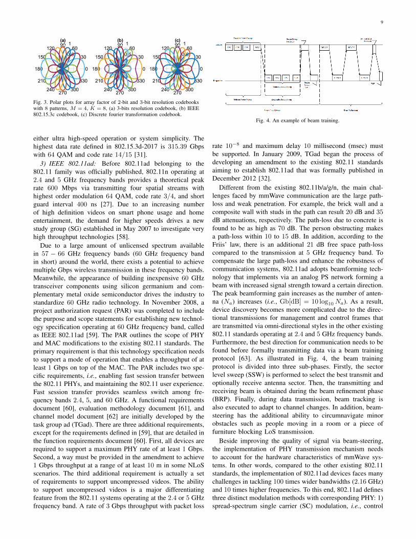
so provides the beamforming codebooks for antenna arraywith uniform spacing of 0.5λ, where λ denotes the carrierwavelength. Each beamforming codebook is identified by thenumber M of antenna elements and the desired number K ofbeam patterns. For the case where K ≥ M , the codebookbeam vectors are given by for m = 0, · · · ,M − 1, andk = 0, · · · ,K − 1,
W (m, k) = jfix{m×mod[k+K/2,K]K/4 } (1)
where j =√−1, function fix (·) returns the biggest integer
smaller than or equal to its argument and mod (a, b) is themodulo operation. The generation of codebooks given by (1)is simple, because they are generated with a 90-degree phaseresolution without adjusting amplitude for reducing powerconsumption. The shortcomings of codebooks generated by (1)are detailed in [11, Section III. C]. Fig. 3 illustrates the polarplots of array factor M = 4 for the 2-bit resolution codebookdefined in 802.15.3c-2009, the 3-bit resolution codebook,and discrete fourier transformation codebook. The codebooksdefined in 802.15.3c-2009 result in the beam gain and lossin some beam directions. The 3-bit resolution beam codebookand discrete fourier transformation codebook provide a sym-metrical uniform maximum gain pattern with reduced sidelobes and a better resolution [11]. Terahertz interest groupestablished in 2008 aims to develop a wireless communicationstandard, i.e., 802.15.3d-2017, operating at Terahertz frequen-cy bands [31]. It is an amendment to 802.15.3-2016 thatdefines an alternative PHY at the lower Terahertz frequencyrange, between 252 and 325 GHz for switched point-to-pointlinks [57]. 802.15.3d-2017 defines eight different channelbandwidths between 2.16 and 69.12 GHz and two kinds ofselectable PHY modes (SC and on-off keying) for achieving
9
Fig. 3. Polar plots for array factor of 2-bit and 3-bit resolution codebookswith 8 patterns, M = 4, K = 8, (a) 3-bits resolution codebook, (b) IEEE802.15.3c codebook, (c) Discrete fourier transformation codebook.
either ultra high-speed operation or system simplicity. Thehighest data rate defined in 802.15.3d-2017 is 315.39 Gbpswith 64 QAM and code rate 14/15 [31].
3) IEEE 802.11ad: Before 802.11ad belonging to the802.11 family was officially published, 802.11n operating at2.4 and 5 GHz frequency bands provides a theoretical peakrate 600 Mbps via transmitting four spatial streams withhighest order modulation 64 QAM, code rate 3/4, and shortguard interval 400 ns [27]. Due to an increasing numberof high definition videos on smart phone usage and homeentertainment, the demand for higher speeds drives a newstudy group (SG) established in May 2007 to investigate veryhigh throughput technologies [58].
Due to a large amount of unlicensed spectrum availablein 57 − 66 GHz frequency bands (60 GHz frequency bandin short) around the world, there exists a potential to achievemultiple Gbps wireless transmission in these frequency bands.Meanwhile, the appearance of building inexpensive 60 GHztransceiver components using silicon germanium and com-plementary metal oxide semiconductor drives the industry tostandardize 60 GHz radio technology. In November 2008, aproject authorization request (PAR) was completed to includethe purpose and scope statements for establishing new technol-ogy specification operating at 60 GHz frequency band, calledas IEEE 802.11ad [59]. The PAR outlines the scope of PHYand MAC modifications to the existing 802.11 standards. Theprimary requirement is that this technology specification needsto support a mode of operation that enables a throughput of atleast 1 Gbps on top of the MAC. The PAR includes two spe-cific requirements, i.e., enabling fast session transfer betweenthe 802.11 PHYs, and maintaining the 802.11 user experience.Fast session transfer provides seamless switch among fre-quency bands 2.4, 5, and 60 GHz. A functional requirementsdocument [60], evaluation methodology document [61], andchannel model document [62] are initially developed by thetask group ad (TGad). There are three additional requirements,except for the requirements defined in [59], that are detailed inthe function requirements document [60]. First, all devices arerequired to support a maximum PHY rate of at least 1 Gbps.Second, a way must be provided in the amendment to achieve1 Gbps throughput at a range of at least 10 m in some NLoSscenarios. The third additional requirement is actually a setof requirements to support uncompressed videos. The abilityto support uncompressed videos is a major differentiatingfeature from the 802.11 systems operating at the 2.4 or 5 GHzfrequency band. A rate of 3 Gbps throughput with packet loss
Fig. 4. An example of beam training.
rate 10−8 and maximum delay 10 millisecond (msec) mustbe supported. In January 2009, TGad began the process ofdeveloping an amendment to the existing 802.11 standardsaiming to establish 802.11ad that was formally published inDecember 2012 [32].
Different from the existing 802.11b/a/g/n, the main chal-lenges faced by mmWave communication are the large path-loss and weak penetration. For example, the brick wall and acomposite wall with studs in the path can result 20 dB and 35dB attenuations, respectively. The path-loss due to concrete isfound to be as high as 70 dB. The person obstructing makesa path-loss within 10 to 15 dB. In addition, according to theFriis’ law, there is an additional 21 dB free space path-losscompared to the transmission at 5 GHz frequency band. Tocompensate the large path-loss and enhance the robustness ofcommunication systems, 802.11ad adopts beamforming tech-nology that implements via an analog PS network forming abeam with increased signal strength toward a certain direction.The peak beamforming gain increases as the number of anten-na (Na) increases (i.e., Gb[dB] = 10 log10Na). As a result,device discovery becomes more complicated due to the direc-tional transmissions for management and control frames thatare transmitted via omni-directional styles in the other existing802.11 standards operating at 2.4 and 5 GHz frequency bands.Furthermore, the best direction for communication needs to befound before formally transmitting data via a beam trainingprotocol [63]. As illustrated in Fig. 4, the beam trainingprotocol is divided into three sub-phases. Firstly, the sectorlevel sweep (SSW) is performed to select the best transmit andoptionally receive antenna sector. Then, the transmitting andreceiving beam is obtained during the beam refinement phase(BRP). Finally, during data transmission, beam tracking isalso executed to adapt to channel changes. In addition, beam-steering has the additional ability to circumnavigate minorobstacles such as people moving in a room or a piece offurniture blocking LoS transmission.
Beside improving the quality of signal via beam-steering,the implementation of PHY transmission mechanism needsto account for the hardware characteristics of mmWave sys-tems. In other words, compared to the other existing 802.11standards, the implementation of 802.11ad devices faces manychallenges in tackling 100 times wider bandwidths (2.16 GHz)and 10 times higher frequencies. To this end, 802.11ad definesthree distinct modulation methods with corresponding PHY: 1)spread-spectrum single carrier (SC) modulation, i.e., control

10
Fig. 5. Frame format of Control, SC, and OFDM PHY defined in 802.11ad.
PHY; 2) SC modulation, i.e., SC PHY and low power SCPHY; and 3) orthogonal frequency division multiplex (OFDM)modulation, i.e., OFDM PHY, as illustrated in Fig. 5. The firsttwo PHY modes must be supported by all devices. The goalof control PHY is to guarantee the basic coverage of mmWavecommunication with low SNR operation prior to beamforming.SC PHY is used to reduce power and transceiver complexityand to achieve the maximum rate (8.805 Gbps) with π/2-64QAM and coding rate 7/8. Low power SC PHY is designedto further reduce the implementation processing power withsimpler coding and shorter symbol structure. OFDM PHY isdesigned for the high performance applications over frequencyselective channels and to achieve maximum data rate 6756.75Mbps by using 64 QAM and coding rate 13/16. However,802.11-2016 has especially emphasized that for 802.11ad, thetransmission and reception of OFDM PHY-layer convergenceprocedure protocol data units (PPDUs) is optional and usingdirectional multiple gigabits OFDM mode is obsolete. Thisimplies that this option may be removed in a later revisionversion [27]. To efficiently and quickly distinguish differentPHY layer PPDU transmission, TGad has carefully designeda preamble sequence that consists of a series of Golay com-plementary sequences having good auto-correlation propertyand simple correlator structure. Further, the three types ofPHYs can be quickly and efficiently distinguished via usingthe sign flip at the end of short training sequence and channelestimation sequence fields [64].
4) IEEE 802.11aj: In general, from the perspective ofsectorized communication networks, one needs at least threeindependent channels to effectively avoid inter-cell interfer-ence. However, there is only two independent 2.16 GHzchannels at 60 GHz frequency band in China, as illustrated inFig. 6 [27]. Motivated by this observation, as early as 2010,SG5 (also known as Q-LinkPAN SG) began investigating thepossibilities of 45 GHz frequency band for application inWPAN [65]. To further standardize the usage of this frequencyband, in January 2012, a new SG for Chinese Millimeter Wave(CMMW) was formed in the 802.11 working group, aimingto study the possibilities of defining enhancements to supportoperation in CMMW frequency bands including 45 GHz and59 to 64 GHz. With the efforts of CMMW SG, 802.11aj PARand five criteria were finished in July 2012 [66].
802.11aj belonging to the 802.11 family is developed by
Fig. 6. Spectral allocations of 60 GHz for WLAN in different countries.
IEEE Standard Associations for two frequency bands, i.e., 45and 60 GHz, to provide high-throughput WLAN communica-tions. As a results, 802.11aj defines two technology specifi-cations operating at different frequency bands. One is Chinadirectional multiple gigabit (CDMG) operating at 60 GHzfrequency band. The other is China millimeter-wave multi-gigabit (CMMG) that operates at 45 GHz frequency band.Different from 802.11ad, two kinds of channel bandwidths,i.e., 1.08 and 2.16 GHz, are defined in the CDMG. Majortechnical specifications in CDMG are similar to those definedin 802.11ad, except for defining some specific technologiesto adapt to the change of channel bandwidth, such that thebackward compatibility can be maintained. But, CDMG onlysupports SC mode transmission.
To further reduce the hardware cost/complexity and powerconsumption, CMMG defines two smaller channel bandwidth-s, i.e., 540 and 1080 MHz. Similarly, CMMG PHY supportsa beam-steering mechanism and includes the control PHY, SCPHY, and OFDM PHY. All devices need to support the firsttwo PHY modes. A sign flip based channel estimation fieldpattern is designed to efficiently distinguish the combinationof the PHY mechanisms and channel bandwidth by using zero-correlation zone sequence. To efficiently exploit the NLoS pathand spatial multiplexing gain, MIMO technology is adopted tosupport multiple data streams (up to four) transmission. Thehighest theoretical rate supported by CMMG PHY is 15.015Gbps with 64 QAM and coding rate 13/16 [33]. Except forexploiting the antenna array gain to compensate for the largepath-loss and weak penetration, a novel low density paritychecking code based robust packet encoding is designed toimprove the code gain with up to 0.2− 0.5 dB [67]. To effec-tively evaluate the performance of mmWave communicationoperating at 45 GHz frequency bands, according to the CMMGtechnology specification defined 802.11aj, a mmWave MIMOprototype communication system based on the BEEcube’sBEE7 platform is built by the research group from the NationalKey Laboratory of mmWave of Southeast University. ThemmWave MIMO prototype communication system consistsof two transmitting antennas and four receiving antennas, inwhich each antenna has a dedicated baseband and RF chain, asillustrated in Fig. 7. The two transmitting antennas consist ofone E-plane horn antenna and one H-plane horn antenna. Thefour receiving antennas consist of two E-plane horn antennasand two H-plane horn antennas. The test results show that the

11
effective data rate 4.085 Gpbs is achieved via transmitting twodata streams on 540 MHz bandwidth. This also validates thatmmWave MIMO communication system with RF chain perantenna is a feasible scheme in certain indoor environments.
13m13m
82m
Radio frequency, IF: 5.77GHz, mmWave: 42-48GHz
Number of antennas: 2 Number of antennas: 4
Power and clock management
Baseband processer
Spectrum analyzer
Signal generator
Intermediate frequency
Local oscillator 7.75GHz
Signal generator
Intermediate frequency
Local oscillator 10MHz
Control panel
Transmitter Receiver
E-plane: 17.04 dB, H-plane: 14.87 dB
Effective data rate
Peak data rate
Receiving
Constellation
Fig. 7. Test platform, environment, performance of 802.11aj CMMG.
5) IEEE 802.11ay: Though 802.11aj operating at 45 GHzfrequency band has been published to support high data rate(up to 15 Gbps) transmission, it can be used only in Chinaas other countries have not opened this frequency band forWLAN applications at present. In addition, 802.11ad operatingat 60 GHz frequency band supports globally the maximumdata rate 8.805 Gbps, but cannot satisfy the demand ofemerging applications or services. More recently, the secondgeneration of 802.11ad (called IEEE 802.11ay) under develop-ment aims to define at least one mode of operations to supporta maximum throughput more than 20 Gbps, while maintainingor improving the power efficiency per station.
Similar to 802.11ad, 802.11ay includes three PHY modes,i.e., control PHY, SC PHY, and OFDM PHY. The first twoPHY modes are mandatory for supporting the following func-tions [34]:
• Enhanced DMG (EDMG) format (transmit and receive);• 2.16 GHz PPDU using EDMG control mode with MCS
0 and SC mode with MCSs 1 − 5 and 7 − 10 (transmitand receive);
• 4.32 GHz PPDU using EDMG control mode with MCS0 and SC mode with MCSs 1 − 5 and 7 − 10 (transmitand receive);
• Single spatial stream (transmit and receive) in all channelbandwidths;
• Normal guard interval type;• 2.16 GHz PPDU using non-EDMG control mode with
MCS 0 and SC mode with MCSs 1 − 4 (transmit andreceive);
• 4.32 GHz PPDU using non-EDMG duplicate controlmode with MCS 0 and SC mode with MCSs 1 − 4(transmit and receive).
In comparison with 802.11ad which has six channels with 2.16GHz bandwidth [27, Table E-1], 802.11ay defines eight chan-nels with 2.16 GHz bandwidth, as illustrated in Table VIII.Further, in addition to retain the advantages of 802.11ad and802.11aj, many novel technologies such as channel bonding,multi-beams transmission, single-user MIMO, and multi-userMIMO transmission are introduced to achieve 20 Gbps datarate. Specifically, the 802.11ay PHY supports the transmission
TABLE VIII. Channelization of EDMG with 2.16GHz bandwidth.
Channel index Start frequency(GHz)
Center frequency(GHz)
Stop frequency(GHz)
1 56.160 57.240 58.3202 58.320 59.400 60.4803 60.480 61.560 62.6404 62.640 63.720 64.8005 64.800 65.880 66.9606 66.960 68.040 69.1207 69.120 70.200 71.2808 71.280 73.360 74.440
of multiple space-time streams, downlink multi-user transmis-sion, and multiple channel bandwidths, including 4.32, 6.48,8.64, 2.16 + 2.16, and 4.32 + 4.32 GHz PPDU transmissions.The channel making up a 2.16 + 2.16 or 4.32 + 4.32 GHzPPDU transmission can be contiguous or non-contiguous. Themaximum number of spatial streams per station is eight. Themulti-user PPDU transmission supports up to eight STAs. For2.16 + 2.16 or 4.32 + 4.32 GHz transmission, the maximumnumber of spatial streams in each channel is four [34].
6) MmWave Cellular Communication: To satisfy the re-quirement of high data rate transmission that is one of the threekey performance indices of future communication systems,new radios exploiting a new spectrum, i.e., mmWave frequencybands, are defined to support new techniques, such as massiveMIMO and flexibility in terms of frame structure, and to targetdifferent use cases and multiple deployment options [68]. Theinternational telecommunication union (ITU) and 3GPP dividethe research of 5G mmWave communication standard into twophases. The first phase, i.e., the research for frequencies lessthan 40 GHz, has completed in September 2018 with aimingto address the more urgent subset of commercial needs. Thesecond phase over 2018 and 2019 focuses on frequencies upto 100 GHz, to address the key performance indices outlinedby international mobile telecommunications (IMT)-2020 [69].
To efficiently develop new radio mmWave technology spec-ification, 11 candidate mmWave frequency bands within therange 24 to 86 GHz were proposed by ITU in 2015 for 5Gbroadband systems. Table IX lists the candidate frequencybands identified in world radio conference 2019 (WRC-19) be-tween 24 and 86 GHz [70]. The allocation within the frequency
TABLE IX. IMT-2020 candidate bands in WRC-19 AI 1.13.Candidate frequency bands
(GHz)Candidate frequency bands of
requirement additional conditions (GHz)24.25− 27.5 31.8− 33.437− 40.5 40.5− 42.542.5− 43.5 47− 47.245.5− 47 −47.2− 50.2 −50.4− 52.6 −66− 76 −81− 86 −
range 52.6 to 116 GHz in ITU radio regulation (ITU-R) islisted in Table X [71]. Protection of some incumbent servicesmay apply and incur in-band and/or out-of-band limitations toIMT-2020 systems. Such incumbent services are documentedin the comments column of Table X, but there is no definitionon the incurred limitations in Radio Regulation.
The main advantage of above 52.6 GHz frequency bands is

12
TABLE X. Frequency bands in the range 52.6 to 116 GHz in radio regulation.
Frequency band(GHz)
Allocated to Mobile Serviceon a primary basis
Allocated to Fixed Serviceon a primary basis Comments
52.6 − 54.25 No No EESS (passive) and SRS (passive), all emissions are prohibited in this band.54.25 − 55.78 No No EESS (passive) and SRS (passive)
55.78 − 59 Yes Yes EESS (passive) and SRS (passive)This band available for high-density applications in the fixed service.
59 − 59.3 Yes Yes EESS (passive) and SRS (passive) Radiolocation.59.3 − 64 Yes Yes Radiolocation.64 − 65 Yes Yes This band available for high-density applications in the fixed service.65 − 66 Yes Yes This band available for high-density applications in the fixed service.
66 − 71 Yes Yes WRC-19 AI 1.13 frequency band, sharing and compatibility studies and potentiallimitations information.
71 − 76 Yes Yes WRC-19 AI 1.13 frequency band, sharing and compatibility studies and potentiallimitations information.
76 − 81 No No Radiolocation.
81 − 86 Yes Yes WRC-19 AI 1.13 frequency band, sharing and compatibility studies and potentiallimitations information.
86 − 92 No No EESS (passive) and SRS (passive), all emissions are prohibited in this band.92 − 94 Yes Yes Radiolocation.
94 − 94.1 No No Radiolocation.94.1 − 95 Yes Yes Radiolocation.95 − 100 Yes Yes Radiolocation.100 − 102 No No EESS (passive) and SRS (passive), all emissions are prohibited in this band.102 − 105 Yes Yes N/A.
105 − 109.5 Yes Yes SRS (passive).109.5 − 111.8 No No EESS (passive) and SRS (passive), all emissions are prohibited in this band.111.8 − 114.25 Yes Yes SRS (passive).114.25 − 116 No No EESS (passive) and SRS (passive), all emissions are prohibited in this band.
Earth Exploration-Satellite Service: EESS; Space Research Service: SRS; Agenda Item: AI;
the abundant spectrum resources, which makes these frequencybands suitable for ultra-high speed transmission. However,the large path-loss and expensive hardware cost restrict theuse cases and deployment scenarios. Considering both the ad-vantages and challenges, the following deployment scenariosshould be considered [71]:
• Ultra-dense services area: The main characteristics ofultra-dense services scenario, such as indoor hot spot anddense urban, are the high requirement of capacity andconsistent user experience, high user density, and lessrequirement on coverage distance;
• Urban/Rural Macro (mainly for fixed wireless accessand backhaul transmission): Although the bands above52.6 GHz have high propagation loss, relatively largecoverage can still be achieved with LoS transmissionand high gain antennas. Therefore, urban/rural macro canbe a deployment scenario for the fixed wireless accessand backhaul applications, which have LoS transmissionconditions;
• Multi-Gbps (ultra-high) data rate services: The scarcity ofspectrum resources at sub-6 GHz frequency bands makesthem difficult to support multiple Gbps (ultra-high) datarate (up to 20 Gbps) services, such as augmented reality,virtual reality, 4K/8K UHD video streaming transmission,D2D connections and high speed wireless backhaul trans-mission. The large bandwidth in the abundant spectrumresources above 52.6 GHz facilitates the realization ofmulti-Gbps (ultra-high) data rate transmission with sim-ple modulation and low power consumption;
• V2X services: Some of the bands above 52.6 GHzare already recommended or identified for informationtechnology system applications by ITU-R, e.g., 57 to 66GHz.
C. Comparison and Discussions
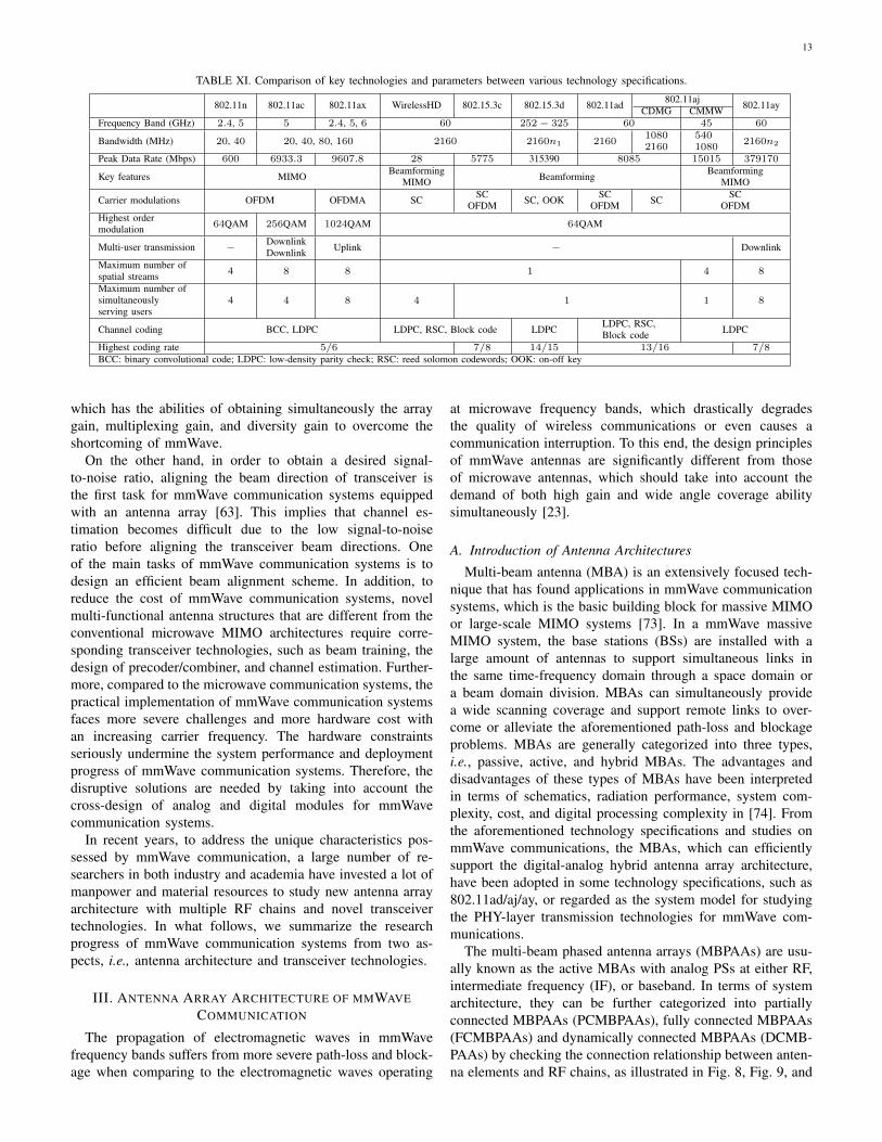
The aforementioned technology specifications have theirown advantages and differences. The comparisons of theirkey technologies are listed in Table XI, where n1 =1, 2, 3, 4, 6, 8, 12, 32, and n2 = 1, 2, 3, 4. In Table XI, 802.11acis an enhancement for high-throughput operation at 5 GHzfrequency band by supporting high order modulation, largenumber of spatial streams, and downlink multi-user transmis-sion [27]. 802.11ax that is an ongoing technology specificationwill replace both 802.11n and 802.11ac as the next genera-tion high-throughput WLAN amendment. The key feature of802.11ax is the adoption of OFDM access (OFDMA), whichis widely used in cellular networks, but brand new in Wi-Finetworks. The interested reader can see the detailed discussionfor 802.11ax [28]. Since this survey focuses on the technologyprogress of mmWave communication, the detailed discussionon the technology progress of below 6 GHz is omitted.
All aforementioned technology specifications adopt antennaarray technology, i.e., beamforming, to compensate for thesevere path-loss and blockage of mmWave. In addition, in802.11aj and 802.11ay, multi-antenna technology, i.e., trans-mitting simultaneously multiple data streams, is further adopt-ed to enhance the transmit rate by exploiting the spatialmultiplexing mechanism. For traditional MIMO communica-tion systems, each antenna has a dedicated RF chain. It alsomeans that for massive MIMO communication systems, a largenumber of RF chains has to be deployed. However, the cost ofhardware implementations increases with an increasing carrierfrequency. Further, a large number of RF chains not onlyconsumes a large amount of energy but also increases the costof wireless communication systems [72]. This implies that itis challenging for mmWave communication systems to equipa dedicated baseband and RF chain per antenna. It is neces-sary to develop a novel multi-functional antenna architecture,
13
TABLE XI. Comparison of key technologies and parameters between various technology specifications.
802.11n 802.11ac 802.11ax WirelessHD 802.15.3c 802.15.3d 802.11ad 802.11aj 802.11ayCDMG CMMWFrequency Band (GHz) 2.4, 5 5 2.4, 5, 6 60 252 − 325 60 45 60
Bandwidth (MHz) 20, 40 20, 40, 80, 160 2160 2160n1 216010802160
5401080
2160n2
Peak Data Rate (Mbps) 600 6933.3 9607.8 28 5775 315390 8085 15015 379170
Key features MIMO BeamformingMIMO Beamforming Beamforming
MIMO
Carrier modulations OFDM OFDMA SC SCOFDM SC, OOK SC
OFDM SC SCOFDM
Highest ordermodulation 64QAM 256QAM 1024QAM 64QAM
Multi-user transmission − DownlinkDownlink Uplink − Downlink
Maximum number ofspatial streams 4 8 8 1 4 8
Maximum number ofsimultaneouslyserving users
4 4 8 4 1 1 8
Channel coding BCC, LDPC LDPC, RSC, Block code LDPC LDPC, RSC,Block code LDPC
Highest coding rate 5/6 7/8 14/15 13/16 7/8BCC: binary convolutional code; LDPC: low-density parity check; RSC: reed solomon codewords; OOK: on-off key
which has the abilities of obtaining simultaneously the arraygain, multiplexing gain, and diversity gain to overcome theshortcoming of mmWave.
On the other hand, in order to obtain a desired signal-to-noise ratio, aligning the beam direction of transceiver isthe first task for mmWave communication systems equippedwith an antenna array [63]. This implies that channel es-timation becomes difficult due to the low signal-to-noiseratio before aligning the transceiver beam directions. Oneof the main tasks of mmWave communication systems is todesign an efficient beam alignment scheme. In addition, toreduce the cost of mmWave communication systems, novelmulti-functional antenna structures that are different from theconventional microwave MIMO architectures require corre-sponding transceiver technologies, such as beam training, thedesign of precoder/combiner, and channel estimation. Further-more, compared to the microwave communication systems, thepractical implementation of mmWave communication systemsfaces more severe challenges and more hardware cost withan increasing carrier frequency. The hardware constraintsseriously undermine the system performance and deploymentprogress of mmWave communication systems. Therefore, thedisruptive solutions are needed by taking into account thecross-design of analog and digital modules for mmWavecommunication systems.
In recent years, to address the unique characteristics pos-sessed by mmWave communication, a large number of re-searchers in both industry and academia have invested a lot ofmanpower and material resources to study new antenna arrayarchitecture with multiple RF chains and novel transceivertechnologies. In what follows, we summarize the researchprogress of mmWave communication systems from two as-pects, i.e., antenna architecture and transceiver technologies.
III. ANTENNA ARRAY ARCHITECTURE OF MMWAVECOMMUNICATION
The propagation of electromagnetic waves in mmWavefrequency bands suffers from more severe path-loss and block-age when comparing to the electromagnetic waves operating
at microwave frequency bands, which drastically degradesthe quality of wireless communications or even causes acommunication interruption. To this end, the design principlesof mmWave antennas are significantly different from thoseof microwave antennas, which should take into account thedemand of both high gain and wide angle coverage abilitysimultaneously [23].
A. Introduction of Antenna Architectures
Multi-beam antenna (MBA) is an extensively focused tech-nique that has found applications in mmWave communicationsystems, which is the basic building block for massive MIMOor large-scale MIMO systems [73]. In a mmWave massiveMIMO system, the base stations (BSs) are installed with alarge amount of antennas to support simultaneous links inthe same time-frequency domain through a space domain ora beam domain division. MBAs can simultaneously providea wide scanning coverage and support remote links to over-come or alleviate the aforementioned path-loss and blockageproblems. MBAs are generally categorized into three types,i.e., passive, active, and hybrid MBAs. The advantages anddisadvantages of these types of MBAs have been interpretedin terms of schematics, radiation performance, system com-plexity, cost, and digital processing complexity in [74]. Fromthe aforementioned technology specifications and studies onmmWave communications, the MBAs, which can efficientlysupport the digital-analog hybrid antenna array architecture,have been adopted in some technology specifications, such as802.11ad/aj/ay, or regarded as the system model for studyingthe PHY-layer transmission technologies for mmWave com-munications.
The multi-beam phased antenna arrays (MBPAAs) are usu-ally known as the active MBAs with analog PSs at either RF,intermediate frequency (IF), or baseband. In terms of systemarchitecture, they can be further categorized into partiallyconnected MBPAAs (PCMBPAAs), fully connected MBPAAs(FCMBPAAs) and dynamically connected MBPAAs (DCMB-PAAs) by checking the connection relationship between anten-na elements and RF chains, as illustrated in Fig. 8, Fig. 9, and

14
(a) (b)
Ant 1
BPF
Ant 1
BPF
Ant 1 Ant 2 Ant M1d
ϕ11
ϕ12
ϕ1M1
Ʃ
BPF
LO
RF 1
PALNA
DPX/S
ADC/DAC
Ant 2 Ant M2d
ϕ21
ϕ22
ϕ2M2
Ʃ
RF 2
PALNA
DPX/S
ADC/DAC
Ant 2 Ant MNd
ϕN1
ϕN2
ϕNMN
Ʃ
RF N
PALNA
DPX/S
ADC/DAC
mixer
Ant 1 Ant 2
d
BPF
ϕ11
ϕ12
ϕ1M1
Ʃ
LNA
DPX/S
DPX/S
LO
RF 1
DPX/S
ADC/DAC
Ant M1
PA
DPX/S
DPX/S
DPX/S
DPX/S
Ant 1 Ant 2
d
BPF
ϕN1
ϕN2
ϕNMN
Ʃ
LNA
DPX/S
DPX/S
LO
RF N
DPX/S
ADC/DAC
Ant MN
PA
DPX/S
DPX/S
DPX/S
DPX/S
mixer
Ant 1 Ant 2
d
BPF
ϕ21
ϕ22
ϕ2M2
Ʃ
LNA
DPX/S
DPX/S
LO
RF 2
DPX/S
ADC/DAC
Ant M2
PA
DPX/S
DPX/S
DPX/S
DPX/S
mixer
LO LOmixer
mixer
Baseband precoding, and so on.
Baseband precoding, and so on.
PA: power amplifier (PA); LNA: low noise amplifier; BPF: bandpass filter; DPX/S: duplexer or a switch; LO: local oscillator; ADC: analog-to-digital converter; DAC: digital-to-analog converter
Fig. 8. Partially connected architecture, (a) passive multi-beam phased array antennas and (b) active multi-beam phased array antennas.
Ɵ
Ant 1 Ant 2 Ant Md
ϕ11
ϕ12
ϕ1M
ϕ21
ϕ22
ϕ2M
ϕN1
ϕN2
ϕ
Ʃ Ʃ Ʃ
NM
(a)
BPF
Ɵ
Ant 1 Ant 2 Ant Md
BPF
ϕ11
ϕ12
ϕ1M
ϕ21
ϕ22
ϕ2M
ϕN1
ϕN2
ϕ
Ʃ Ʃ Ʃ
NM
LO
RF 1
PALNA
DPX/S
ADC/DAC
RF 2
PALNA
DPX/S
ADC/DAC
RF N
PALNA
DPX/S
ADC/DAC
mixer
PALNA
DPX/S
DPX/S
PALNA
DPX/S
DPX/S
PALNA
DPX/S
DPX/S
LO
RF 1
DPX/S
ADC/DAC
RF 2
DPX/S
ADC/DAC
RF N
DPX/S
ADC/DAC
mixer
(b)
Baseband precoding, and so on.
Baseband precoding, and so on.
PA: power amplifier (PA); LNA: low noise amplifier; BPF: bandpass filter; DPX/S: duplexer or a switch; LO: local oscillator; ADC: analog-to-digital converter; DAC: digital-to-analog converter
Fig. 9. Fully connected architecture, (a) passive multi-beam phased arrayantennas and (b) active multi-beam phased array antennas.
Fig. 10, respectively. Note that uniform linear array (ULA)is illustrated as an example in each figure, and the followingdiscussions can be either applied to a two-dimensional panelantenna array which is also an implementation style of MBAarchitecture. The architectures of PCMBPAAs, FCMBPAAs,and DCMBPAAs have abilities to fulfill the high-densityintegration requirements raised in mmWave frequency bands.For this reason, the three types of MBPAAs are discussedand compared in the following. Further, another type ofpassive MBAs, based on quasi-optical method, is very popularin mmWave communications due to the low loss and easyimplementation of multi-beam performance, i.e., reflector- orlens-based MBAs, which are also reviewed and compared withthe active MBAs.
1) PCMBPAAs: Two typical PCMBPAAs architectureswith RF PSs are illustrated in Fig. 8, which are popular andhighly attractive for mmWave communications. For example,
Ɵ
Ant 1 Ant 2 Ant Md
ϕ11
ϕ12
ϕ1M
ϕ21
ϕ22
ϕ2M
ϕN1
ϕN2
ϕ
Ʃ Ʃ Ʃ
NM
(a)
BPF
Ɵ
Ant 1 Ant 2 Ant Md
BPF
ϕ11
ϕ12
ϕ1M
ϕ21
ϕ22
ϕ2M
ϕN1
ϕN2
ϕ
Ʃ Ʃ Ʃ
NM
LO
RF 1
PALNA
DPX/S
ADC/DAC
RF 2
PALNA
DPX/S
ADC/DAC
RF N
PALNA
DPX/S
ADC/DAC
mixer
PALNA
DPX/S
DPX/S
PALNA
DPX/S
DPX/S
PALNA
DPX/S
DPX/S
LO
RF 1
DPX/S
ADC/DAC
RF 2
DPX/S
ADC/DAC
RF N
DPX/S
ADC/DAC
mixer
(b)
Baseband precoding, and so on.
Baseband precoding, and so on.
PA: power amplifier (PA); LNA: low noise amplifier; BPF: bandpass filter; DPX/S: duplexer or a switch; LO: local oscillator; ADC: analog-to-digital converter; DAC: digital-to-analog converter
Switch SwitchSwitch
Switch Switch Switch
Fig. 10. Dynamically connected architecture, (a) passive multi-beam phasedarray antennas and (b) active multi-beam phased array antennas.
802.15.3c and 802.11ad adopt this structure with a single RFchain (i.e., N = 1), while 802.11aj adopts it with a singleRF chain or multiple RF chains. As shown in Fig. 8(a), thepassive PCMBPAA with RF PSs is comprised of N RF chains.Each RF chain is connected with a Mi-element ULA through
a group of Mi RF PSs, so a total number of M =N∑i=1
Mi
antenna elements are employed. Each chain has an identicaltransceiver connecting the ULA through either a diplexer ora switch depending on whether a frequency domain divisionor a time domain division is adopted, and all these chains areconnected to a common baseband. Thus, this type of passivePCMBPAA can generate multi-beams in a two-peripheral way,controlled either by the Mi RF PSs contained in the subarrayof each chain or by the baseband precoding of the entireantenna system. Fig. 8(b) illustrates the architecture of anactive PCMBPAA, which has an apparent difference from the

15
passive one in that the PSs and the RF transceivers are re-configured. Each antenna element, followed by a bandpassfilter (BPF), connects to its own low-noise amplifier (LNA)and power amplifier (PA) through either a diplexer or aswitch. The RF PSs are inserted in-between the LNAs/PAsand the mixers contained in each RF chain, and with a totalnumber of M . The mixers in either Fig. 8(a) or Fig. 8(b)are connected to baseband through a pair of analog-to-digitalconverter (ADC) and digital-to-analog convertor (DAC). Thereare all together N pairs of ADCs/DACs. Thus, the scale ofthe active PCMBPAA is the same as that of the passive onein terms as antenna array. Two-folded enhanced performanceis achieved by using such a different architecture: First, thesystem noise figure as well as the receiving sensitivity can beimproved due to the LNAs are placed close to the antennaelement since the phase shifter is relocated at the place afterthe LNA in the receive chain. Second, there are totally N×MPAs, which can jointly generate a high level of RF powerand provide good linearity by adopting a power combinationin free space. Meanwhile, the insertion loss of phase shifterscan be compensated since the power is amplified by the PAbehind the phase shifter in the transmitting chain. A similartwo-peripheral phase-shifting scheme, as mentioned in thepassive PCMBPAA, is also supported in the active PCMBPAA.It controls the phases of the antenna elements via the RFPSs and the baseband precoding simultaneously. A commondrawback of PCMBPAAs, including both the passive andactive architectures, is that each subarray can generate onlyone beam at one time, leading to a low aperture utilizationefficiency. The full-angle coverage is realized by using themultiple beams generated by the N subarrays. By increasingMi, i.e., the number of the antenna elements in each subarray,much narrower beamwidth can be achieved. However, the dis-tance between any two adjacent subarrays should be increasedaccordingly, which results in a reduced scanning range andeven the presence of grating lobes. Therefore, PCMBPAAs areapt to be adopted at BSs or access points to provide a full areacoverage with multi-beams. In such scenarios, the size of theantenna array is not stringent and large-scale antenna arrayscan be used to generate a great number of narrow beams so thatthe coverage depth and width are enhanced simultaneously.Specially, if the scale of PCMBPAA reduces to N = 1, thenit can also be applied in mobile terminals, because in this caseit is transferred into a conventional phased array. This simplestPCMBPAA is widely used in 5G commercial terminals.
2) FCMBPAAs: To improve the aperture utilization effi-ciency or to generate concurrent beams for wide angle cov-erage and suppressing grating lobes, fully connected MBPAA(FCMBPAA) architecture is proposed as shown in Fig. 9, in-cluding both passive and active FCMBPAAs. Passive FCMB-PAA, as illustrated in Fig. 9(a), has M antenna elements,N RF chains, and N × M RF PSs. Different from passivePCMBPAA, each antenna element in passive FCMBPAAconnects to all N RF chains simultaneously through a groupof M RF PSs, respectively. All antenna elements are simulta-neously contributing to generate N concurrent beams, whichcan further reduce the number of antenna elements whencompared with passive PCMBPAA or reach a higher antenna
gain when having the same number of antenna elementsas the passive PCMBPAA. Similar conclusion can be madebetween active FCMBPAA and active PCMBPAA. The twotypes of active MBPAAs are different in that each antennaelement in active FCMBPAA is connected to one channelthrough a group of RF PSs, which results in N concurrentbeams as each antenna element is excited by N RF chainssimultaneously. In comparison, FCMBPAAs have advantagesof the reduced number of antenna elements or high utilizationon antenna elements and the PHY aperture of antenna array.Furthermore, without any subarray, the theoretical scanningangle is much wider than that of PCMBPAAs. While, thereshould be no grating lobe when the distance between any twoadjacent elements equals a half operating wavelength. Due tothe higher aperture utilization efficiency and wider scanningangle range, FCMBPAAs are potentially used in the scenarioswhere the antenna size is the priority consideration. Thus, incompact BSs or accessing points, FCMBPAAs are a promisingarchitecture to support high density coverage and high datarate transmission through the simultaneously radiated multi-beams in a limited aperture [75]. In certain applications,small-scale FCMBPAAs can also be implemented on mobileterminals so that the design complexity, hardware cost, as wellas power consumption can be greatly reduced with a compactsize.
3) DCMBPAAs: Dynamically connected MBPAA (DCMB-PAA) is achieved by extending an FCMBPAA through insert-ing the switching array in-between the PSs and RF chains. ADCMBPAA can fulfill either an FCMBPAA or a PCMBPAAby controlling the switching states. Specifically, when all theswitches are with on state, each RF chain is connected to all ofthe antenna elements through PSs, resulting in an FCMBPAAs.To realize PCMBPAAs, all the antenna elements are dividedinto N clusters, and the antennas in each cluster are connectedto one specific RF chain by adjusting the switches. The insert-ed switching array does not apparently increase the complexityand the cost of the system comparing with FCMBPAAs, butit offers flexibility for DCMBPAAs in different applicationscenarios with a minimal expense of insertion loss. SinceDCMBPAAs can transfer to PCMBPAAs or FCMBPAAsby controlling the used switch arrays. DCMBPAAs can beapplied in BSs, accessing points or mobile terminals, and thescale of a DCMBPAA can be flexibly configured accordingto the specific application scenarios. For instance, for BSapplications, the scale of DCMBPAAs can be sufficiently largeto support large area coverage and high density connections.Favorably, a DCMBPAA can also be reconfigured accordingthe real-time requirements so that it can be operated as anFCMBPAA in business hours and simplified to a PCMBPAAin later night. Such reconfigurability of DCMBPAAs is alsoattractive in mobile terminals.
A comparison among the three types of MBPAAs is shownin Table XII under the assumption of the same RF chainsused in each type of MBPAAs. Note that, in PCMBPAAs,only a subarray of antenna elements can be utilized for eachbeam, thus its gain is usually lower than the other two types ofMBPAAs, of which the full antenna array contributes to eachbeam. Meanwhile, the subarray topology used in PCMBPAAs

16
TABLE XII. MmWave channel estimation summary.
Number of RF Chains Number of Antenna elements Antenna Array Gain Beam Sweeping Range Cost
PCMBPAAs NN∑
i=1Mi Moderate Narrow Moderate
FCMBPAAs N M Moderate Wide HighDCMBPAAs N M Highest Flexible Highest
Top View of Antenna Station
Side View of Antenna Station(Cross Section)
Subreflector
Main reflector
TX/RXinside
Focal-Plane Array
6
Fig. 11. Focal-plane array for 5G-mmWave communication.
cannot support wide-angle beam sweeping (coverage), but theRF architecture of PCMBPAAs is the simplest. DCMBPAAsis a flexible candidate in terms of both performance andcomplexity.
4) Reflector- or Lens-based MBA: In mmWave frequencybands, both the aforementioned passive/active PCMBPAAs,FCMBPAAs, and DCMBPAAs are rarely deployed at a largescale, due to the system complexity and huge cost of mmWavechains, especially the PSs. Passive MBAs, active MBAs, orhybrid MBAs without or containing less RF PSs are preferredalternates. In the following, MBA architectures are reviewedfor either macro BSs, micro BSs, customer premise equipment(CPEs), and user equipment (UE), respectively, in variousapplication scenarios as shown in Fig. 1, to ensure sufficientcoverage as well as robust connections at both low system costand complexity.
For both macro and micro BSs, the passive MBAs dominatebecause they can radiate multiple concurrent beams withoutthe requirement of a complex BS system when comparedwith active or hybrid MBAs [74]. As omnidirectional beamcoverage is essential for macro BSs, MBAs with wide scanningangles as well as high gains should be adopted to achievean effective isotropic radiation power for large coverage. Asshown in Fig. 11, as a promising candidate, the focal-planearray with broadband optical beamforming property is recentlyproposed and experimentally prototyped at 28 GHz [76]. Forthe same purpose of providing multiple beams with widescanning angles, flat lens based or Luneburg lens basedMBAs are recently implemented for Ka-, V-, and E-bands,respectively. They exhibit desired performance such as widescanning angle, a large number of concurrent beams, flat gainenvelope, and easy of installations [77], [78]. A metamaterial-based planar lens is presented with seven feeders to achievea seven beams [79], which shows that the lens antenna hasan advantage to realize multi-beams with a simple structure.Further, a folded reflectarray is implemented to provide multi-beams for wide angle coverage with the presence of multiple
feeders [80]. The meta-surface based multi-beam array hasbeen further implemented in a two dimensional form forpractical applications [81]. The reflector- or lens-based MBAshave a simple structure, low insertion loss, and high efficiency,resulting in better performance at mmWave frequency bandsthan other types of passive MBAs configured with beamform-ing networks, i.e., Butler matrix [82], Rotman lens [83], andintelligent metasurfaces [84].
The lens antenna has multiple feeders located on the circleof its focus, and each feeder is connected an RF chain throughthe beam selector which is a switch-array to determine theconnection between the RF chain and the feeder by switches.All the RF chains are connected to the baseband, as shown inFig. 12. The multi-beam pattern is generated by the lens andfeeders only, which is regarded as an air-feed scheme or opticalfocus. Thus, it has a simple structure when comparing to theMBPAAs, since no phase shifters are required. Moreover, theRF chains are connected to feeders one by one to form isolatedRF-feed chains, which means the numbers of RF chains andfeeders are equal. Since no intersection or crossover is neededin-between different RF-feed chains, the RF infrastructure ismuch simpler. All the beams can be radiated simultaneouslyor only several or only one beam is radiated by switching thebeam selector, without any loss on the signal [85]. In short,the type of reflector- or lens-based MBAs is better than thePCMBPAAs, FCMBPAAs and DCMBPAAs, in terms of ar-chitecture, cost, and simultaneously multi-beam performance.But the cost of larger bulk size due to the focal length aswell as large aperture of reflector and lens should be kept.This type of MBAs is apt to be equipped in BSs. Meanwhile,it is a low power-consumption solution for energy-efficientor energy-limited systems, because the used reflector or lenscan generate relatively high gain to relieve the output of PAs.As mentioned in [74] and [75], there are also circuits basedreflectors or lens designs, which have been explored for multi-beams or massive MIMO applications. The loss introduced bythe circuits or transmission lines are server than that of air-fedreflectors and lens. Moreover, due to the conventionally planarform of the circuit-based components, a two-dimensional beamscanning is always a design issue.
B. Discussion and Conclusions
Active MBAs, especially MBPAAs, are another choice forBSs, because their RF circuits can provide much flexiblefunctions of amplitude and phase control. However, high costand complex RF circuit infrastructure are required. Therefore,active MBAs are ususally developed for micro BSs and CPEs,which have much lower requirements of the number of beamsand scanning ability than macro BSs, and achieves a trade-off between cost and performance. Especially, for applicationscenarios with low mobility and the requirement of high data

17
Beam
Selector
Baseband Signal Processing
RF Chain
Ufa
Udla
Discrete Lens Array (DLA)P
Fig. 12. Lens antenna arrays.
rate, e.g., indoor access or point to point links, active MBAswill have certain advantages due to their flexible beam switch-ing. Active MBAs can be further divided into RF-domain,inter-frequency (IF)-domain, local oscillator (LO)-domain, andbaseband-domain active MBAs. The circuit domain (includingRF-, IF-and LO-domain) MBAs are extensively investigatedand experimented in mmWave high density integrated circuit-s [86]. The scale of integrated antenna elements is significantlyincreased from a few to a large number, e.g., 64, 128, 256 oreven more because of the increasing integration density ofputting multiple channels into a single chip [87]. Differentfrom the widespread circuit domain MBAs, the design of apure baseband-domain MBA, known as fully digital MBA,is carried on on the digital processing circuits. A 64-channelfully digital MBAs has been successfully developed at 28 GHzwith a bandwidth of 500 MHz, which can achieve a peakdata rate of 50.73 Gbps with a spectrum efficiency of 101.5Bps [88]. However, the hardware complexity and limited dataprocessing rate pose a great challenge for its extensive appli-cations. To achieve a balance between the performance andhardware cost, hybrid MBAs are competitive candidates formmWave communication [89]. The concept of hybrid MBAsis simple, which is an agile combination of aforementionedactive MBAs, passive MBAs, and digital MBAs. In contrast,the promising topologies and infrastructures for hybrid MBAsare very versatile, because the potential combinations seemto be uncountable, and different type of hybrid MBAs canprovide different yet competing performance. To this end, thedesign and implementation of hybrid MBAs not only are thefocus of antenna design, but also should be evaluated from aperspective view of the system architecture.
In the aforementioned MBPAAs, the control of phase forantenna arrays is implemented with PSs, as illustrated inFig. 8, Fig. 9, and Fig. 10. Conventionally, the PSs are widelyused in RF circuits design due to its mature fabrication,stable performance and low cost, but they are suffering lim-ited bandwidth problems. Because the phase delay providedby conventional PSs cannot fulfill the required frequency-dependent phase shifting for array elements, thus a beamsquinting will be happened within a relative wide bandwidth.To alleviate this problem, in another words, to maintain astable beam steering over a wide bandwidth, the true timedelay method is proposed by using the delay line structuresto ensure a stable time delay [90]. Thus, the equivalent phase
delay is frequency-dependent, which matches well with thefrequency-dependent phase delay requirement for stable beamsteering [91]. Nevertheless, the aforementioned MBPAAs canalso be supported by the true time delay method, with anenhancement of bandwidth.
The extraordinary growth of electronic devices drives thedevelopment of mmWave mobile connection technologies tosupport data-hungry applications. The mmWave antennas forUEs contribute to another emerging research hotspot in recentyears, among which the integration of mmWave antennasinto the UEs and UE-level phased antenna arrays is highlyattractive [92]. The most important property of mmWaveantennas in UEs is the mobility and coverage ability, which isseverely reduced when considering the blockage of mmWave,such as the hand holding and body blockage. Hence, phasedarray appears to be the first choice to solve the problemby using either beam scanning or beam switching [93]. Fur-thermore, two or three or even more phased array units canbe inserted into a UE to enhance its coverage performancethrough a sectorial concept. However, the corresponding powerconsumption and hardware cost need further investigation [94].
IV. ENABLING PHY-LAYER TRANSMISSIONTECHNOLOGIES
To efficiently exploit the potentials of multi-antenna tech-nologies, e.g., multiplexing, diversity, and array gain, it isrequired to carefully design multi-antenna transceiver forwireless communication systems. Though the principle ofdesigning transceiver is not closely related to the specificcarrier frequency, the design of antenna architectures needs totake into consideration the hardware cost and implementationcomplexity that depend on the specific carrier frequency. Fur-thermore, the specific design of transceiver schemes for pre-coding and combining depends on the hardware architecture,propagation environment, and practical requirements of vari-ous services. The distinct propagation characteristics betweenmmWave and microwave frequency bands lead to disparatesignal processing methods for transceiver optimization [16].For digital processing which adjusts digitally the signal phaseand amplitude at baseband, each antenna element requires adedicated baseband and RF hardware. However, in mmWavecommunication systems, it is impossible to equip with adedicated baseband and RF hardware for each antenna elementdue to the prohibitive high cost and power consumption.Therefore, how to balance the hardware cost, implementationcomplexity, and system performance has attracted extensiveinterests in both industry and academia in the past few years.The main contents discussed in this section are illustrated inFig. 13.
A. Channel Estimation and Tracking
1) Channel Estimation: To benefit from the potential gainsprovided by multi-antennas, one of the most important ele-ments is to obtain the CSI at transceiver. Consequently, CSIestimation has been under extensive investigation for wirelesscommunication systems. However, different from traditional

18
Fig. 13. Enabling PHY-layer transmission technologies discussed in this section.
TABLE XIII. MmWave channel estimation summary.
Antenna architecture Methods Estimated parameters Comments Ref. YoP
Fully digital Overlapped beam pattern
AoAs, AoDs, Path gains A lot of beam training overhead. For each channelestimation, it is necessary to retrain the beams andrun the corresponding algorithm.
[95] 2017Hierarchical codebook [96] 2018
Fully connectedTop-P gain beam pairs [97] 2018
Compressed sensing [98] 2014[99] 2018
Fully digital Bayesian estimation Channel coefficient [100] 2019Compressed sensing AoAs, Delay, Path gains [101] 2020
Fully connected Multiple signal classification method [102] 2017
Lens array Learned denoising-based approximatemessage passing neural network
Channel coefficient A large amount of data collected is needed for modeltraining and testing. Model training takes a long time.
[103] 2018
Fully connected Fast and flexible denoising convolutionalneural network [104] 2019
Lens array Fully convolutional denoising network andU-Net [105] 2020
Fully connected
Convolutional neural network andspatial-frequency-temporal correlations [106] 2019
General iterative index detection AoAs, Path gains Running algorithm for each channel estimation. [107] 2018Multiple frequency tones [108] 2017
MIMO communication systems operating at microwave fre-quency bands, the unique characteristics of mmWave prop-agation makes the CSI estimation more challenging. Thechallenges mainly reflect in two-fold. First, the signal-to-noise ratio for channel estimation may be very low withthe lack of array gains before establishing data transmissionlinks due to the spatial angular sparsity and large path-lossof mmWave. Second, constrained by the expensive hardwarecost and considerable high power consumption, the number ofRF chains is usually much smaller than that of antennas in ahybrid architecture system. It implies that each RF unit cannotobtain simultaneously the sampled signals from each antenna,i.e., can only obtain a combination of sampled signals from
all antennas [14]. As a result, the conventional pilot assistedchannel estimation algorithms for fully digital systems cannotbe directly applied to acquire the explicit CSI of mmWavecommunication systems. In recent years, how to efficiently andeffectively estimate the CSI has attracted extensive attentions.Table XIII lists some channel estimation methods for mmWavecommunication systems.
Codebook based channel estimation: The first approach isto estimate an equivalent channel via codebook-based multi-stage beam training. The equivalent channel is the products ofthe adopted analog beams and the real PHY channel. Yet, theprecision of this method mainly depends on the beamwidth andthe mobility of terminals. To implement this approach, in gen-

19
eral, a high training overhead is needed for pairing transceiverbeams, which depends on the resolution of analog beamcodebooks designed. Using the analog beamforming tech-niques, the most straightforward channel estimation methodis to exhaustively search in all possible angular directions.After finishing beam training, a virtual channel matrix can beformed, whose entries represent the channel gains between theM transmit and N receive beams. Recalling the sparse propa-gation characteristics in the angular domain of mmWave, onecan effectively generate the equivalent channel by identifyingthe transmit and receive direction pairs with maximum gain.To reduce the number of channel estimation measurementsand improve estimation accuracy, a fast mmWave MIMOchannel estimation framework is developed by designing aset of novel overlapped beam patterns [95]. In the proposedscheme, the authors design a maximum likelihood detector tooptimally extract the angle of departure (AoD) and angle ofarrive (AoA) information from the measurements and a linearminimum mean squared error channel estimator to estimatethe channel coefficients by optimally combining the selectedmeasurements in all stages. The authors of [96] propose amultipath decomposition and recovery approach to estimatethe mmWave channel by using hierarchical search based ona normal-resolution codebook. A top-P reconstruct approachis proposed to generate the channel matrix by exploitingthe beam direction pairs with the top-P gain for mmWavecommunication systems [97].
Compressed sensing based channel estimation: This methodfully exploits the spatial angular sparsity of mmWave propa-gation to estimate the AoA, AoD, and complex path gains.Then, the channel matrix can be constructed via the obtainedAoA, AoD, and complex path gains [98]. The most popularapproach is to estimate the channel matrix by combiningthe dictionary matrix and beam training codebook with thecompressed sensing theory. The fundamental idea of theseapproaches is to search multiple transmit/receive directionsin each measurement by creating initial beam patterns [99].By leveraging the inherent sparsity of mmWave channel,the channel estimation problem is transformed into a re-construction problem of compressible signals from a set ofnoisy linear measurements. Then, the entries of the unknownmmWave MIMO channel matrix is found via the generalizedapproximate message passing algorithm [100]. Recently, byexploiting the angle-delay sparsity of mmWave transmission,a compressive sensing based channel estimation algorithm isdesigned to estimate the channel of mmWave massive MIMOcommunication system, with taking beam squint into accoun-t [101]. Meanwhile, the classical multiple signal classificationmethod is used to estimate the AoA/AoD. Then, the least-squares method is used to estimate the complex path gain.Different from its element-space counterpart, the beamspacemultiple signal classification method may exhibit spectrumambiguity caused by the beamformers [102].
Machine learning based channel estimation: Recently, ma-chine learning based channel estimation methods arose tomake full use of the inherent characteristics hidden in da-ta/signals collected in an end-to-end manner. For example,considering the sparse mmWave channel matrix as a natu-
ral image, a learned denoising-based approximate messagepassing neural network is applied to construct the channelestimation model for beamspace mmWave systems [103].However, the performance of this learning model is limitedby the noise level. To address this problem, a fast andflexible denoising convolutional neural network is used tobuild channel estimation framework for cell-free mmWavesystems [104]. Further, based on the aforementioned machinelearning methods, a blind channel estimation algorithm withfully convolutional denoising network and U-Net is developedto overcome their shortcomings [105]. By exploiting thespatial-frequency-temporal correlation, a deep convolutionalneural network is designed to estimate the channel in mmWavecommunication systems [106]. These research results showthat machine learning based channel estimation methods aremore capable to extract the inherent characteristics of thechannel from a large amount of data collected and have thepotential to estimate the channel more accurately with lowercomplexity. However, the fast changing of communicationenvironments requires the deep learning model to be adaptive,that is, it must have a strong scalability and generalizationabilities.
Other channel estimation methods: In some special cases,the scatters may be abundant for mmWave communication,namely, mmWave channel may be correlative. The spatialcorrelation of channel can be used to estimate the channel ofmmWave MIMO systems with hybrid antenna array structure.With the help of pilots, a general iterative index detection-based channel estimation algorithm is proposed for the uplinkof mmWave multi-user communication system [107]. Thestrongest AoAs at BS and user sides are estimated by exploit-ing multiple frequency tones for mmWave multi-user downlinksystem [108]. Then, the devices transmit orthogonal pilotsymbols to BS along the estimated strongest AoA directionsfor estimating the equivalent channel.
2) Channel Tracking: Due to the requirement of the di-rectional propagation of mmWave, one may consider thatmmWave communication is suitable only for a static commu-nication environment, such as fixed D2D communication, asillustrated in Fig. 1. In practice, to accommodate the terminalmobility, real-time beam alignment and channel estimationshould be executed frequently, which leads to high resourceoverhead. Furthermore, in mmWave frequency bands, the usermobility exacerbates Doppler effects and leads to very shortchannel coherence time. This means that mmWave channelsvary quickly, even when considering the short symbol durationassociated with large bandwidth. Therefore, for mmWavecommunication, there is no enough time to continuously repeatbeam training from scratch. This implies that maintainingbeams towards mobile users and adapting to frequent blockagerequire efficient and dynamic channel-tracking or path trackingalgorithms. A comparison of the research on channel-trackingis listed in Table XIV.
To support dynamic beam tracking, both 802.11ad and802.11aj suggest to add automatic gain control subfield andbeam training subfields (TRN-T/R) at the end of data frames totrack channel variations [32], [33]. Beam tracking stage is anoptional stage, that is used to track the changes in the transmit

20
TABLE XIV. MmWave channel tracking summary.
Tracking method Comments Type Ref. YoPTheory PlatformBeam tracking is conducted during data transmission. Large pilot overheads. X X [63] 2009
A priori knowledge aided channel tracking.Need prior data to excavate a temporal variation law ofthe physical direction. Tracking time-varying channelswith low pilot overhead.
X [109] 2017
Noncoherent compressive tracking with signal strength received. Need relatively slow feedback overhead from terminals. X X [110] 2017
Leaky wave antenna based path discovery. Transmitting distinct signals with unique signatures acrossdifferent angles. X X [111] 2020
Particle filtering based beam tracking. Need to transmit a series of training pilots that depend onthe number of beam pairs used at transceivers. X [112] 2019
Auxiliary beam pair-assisted angle tracking. Need to additional auxiliary beam pairs based on theconventional beam training. X [113] 2018
Unscented Kalman filtering based channel tracking. Need initial channel estimation information. X [114] 2019Machine learning based beam tracking. Need a large number of training and test data. X X [115] 2020Multi-armed bandit based beam tracking. Middle pilot overheads.. X [116] 2020Graph neural network based channel tracking. Need a large number of training and test data. X X [117] 2020Deep learning based channel tracking. X X [118] 2020
and receive weight vector due to channel variation overtime [63]. An alternative solution of tracking the mmWavechannel changes is to track the LoS path of channel by utilizingthe geometric relationship between the transmitter and receiv-er. Some prior knowledge can be used to track the angle, i.e.,priori-aided angle tracking strategies, which include two mainsteps. The first step is to acquire the temporal variation lawof the AoD and AoA of LoS path. Then, the support set (theindex set of non-zero elements in a sparse vector) of channelis predicted by jointly using the temporal variation law of LoSpath and the sparse structure of mmWave channels [109]. Thecore idea of path tracking is to filter the spatial propagationpath. A noncoherent compressive tracking scheme is designedto estimate the dominant path between BS and user with verysmall beacon overhead at sub-second time scales [110]. One-shot path discovery scheme is studied via transmitting distinctsignals with unique signatures across different angles such thateach physical path has its own signature [111]. Lim et al.propose to use particle filtering approaches for tracking thetime-varying beam channel to update the beamforming andcombining vectors [112]. An auxiliary beam pair based high-resolution angle tracking strategies is investigated for mmWavewideband systems with mobility [113]. The authors furtherinvestigate the impact of the array calibration errors on theauxiliary beam pair design from the perspective of practicalimplementation. In addition, other beam tracking algorithms,such as the adaptive beam tracking [114], are designed formmWave communication systems.
In general, channel-tracking aims to estimate the directionsor locations of mmWave users in varying environments. Inthe case of high mobility of terminals, e.g., in the high speedrailway scenario, the conventional beam tracking strategiesbecome inefficient. Tracking a user’s trajectory and velocityhelps predict his location changes, which further speeds up thebeam tracking and adjustment in mobile mmWave networks.Machine learning methods have the ability to predict the user’slocation changes via recording a large amount of historytrajectory data. Meanwhile, by sensing the change of theenvironment, the learned pattern of beam change is used toguide the beam alignment by using the ε-greedy strategy orthe upper confidence bound strategy [116]. In addition, witha small amount of training overhead, the channel-tracking
algorithms based on machine learning and initial channelestimation are also studied, such as graph neural networkbased [117] and long short-term memory based channel-tracking [118]. These researches show that making full use ofthe information of communication environments for channel-tracking is crucial for adapting the high dynamic communica-tion scenarios. Meanwhile, studying real-time one-shot deeplearning networks is also an important direction for mmWavecommunication systems due to the difficulty of obtainingmassive training data and the demand of lightweight mobiledevices with low power consumption.
B. Analog Beamforming
Constrained by the high hardware cost and high powerconsumption of mmWave communication systems, early re-search on mmWave communication focuses on improving thepropagation distance of mmWave at an acceptable hardwarecost. Consequently, analog beamforming that is implementedusing PS networks becomes a natural choice for mmWavecommunication systems. Analog beamforming is essentially aspatial filtering operation typically using an array of radiatorsto capture or radiate energy in a specific direction overits aperture. In general, the design of analog beamformingcan be divided into two categories, i.e., one is based onthe predefined codebook and the other is implemented viaestimating AoA/AoD.
Analog beamforming based on codebook: A codebook is amatrix in which each column specifies a beam weight vectorthat corresponds to an unique beam pattern. The goal ofthe design of analog beamforming based on codebook is tomaximize certain criterion, such as the signal-to-interference-plus-noise ratio or signal-to-noise ratio, by identifying the bestbeam pair for data transmissions from the set of possibletransceiver beam pairs. The optimal solution is to perform abrute force search over the set of possible transceiver beampairs, but this requires too much over-the-air overhead todetermine the best beam pair. Alternating beam alignment(training) between transceiver is one of the most commonlyused methods [119]. To reduce the alignment overhead, three-stage protocol, i.e., D2D linking, sector-level searching, andbeam-level searching, and two-stage protocol, i.e., sector-level searching and beam-level searching, have been adopted

21
TABLE XV. Analog beam alignment summary.
Architecture Scheme Criterion Mode Ref. YoP
Single RF chainThree-stage downlink-uplink alternative beam alignment Maximizing received power Single-user [63] 2009
Two-stage downlink-uplink alternative beam alignment Maximizing received power Multi-user [129] 2019[130] 2019
Multiple RF chainsFully connected Interleave assisted beam alignment Minimizing outage probability Single-user,
Multi-user [119] 2018
Single RF Location assisted alternative beam alignment Maximizing received SNR Single-user [121] 2019
Multiple RF chainsFully connected
Alternative beam alignment, blockage control strategies and multi-usermulti-beampower allocation Maximizing sum rate Multi-user [122] 2019
Multi-resolution codebook, adaptive multilevel beam alignment, sequence design Maximizing received powerSingle-user
[123] 2017Single RF chain Alternative beam alignment, Hierarchical codebook design Minimizing delay [124] 2016
Multiple RF chainsFully connected
Acquiring candidate beam pair links for heterogeneous network,Concurrent beam codebook design Maximizing sum rate
Multi-user[127] 2018
Adaptive beam training protocols, Concurrent beam codebook design Maximizing received power [128] 2017
respectively by the 802.15.3c [30] and 802.11ad [32]. Thesetwo protocols still require significant alignment overheads todetermine the best beam pair. As the constant antenna weights(amplitude and/or phase) are applied to the array elements tosteer the main beam, even a slight beam misalignment betweentwo communicating devices (for example, due to mobility)deteriorates system performance [120]. This leads to the fre-quent invocations of time-consuming mechanisms for beam re-alignment. To this end, some side information extracted fromthe data packets and the position of terminals may be used tospeed up selecting the analog beam pair from the codebook-s [121]. Another factor affecting beam alignment overhead isthe predefined codebooks [122]. Therefore, properly designingcodebook can efficiently promote the effectiveness of analogbeam alignments, such as the multi-resolution codebook [123]and multi-stage beamforming codebook [124]. By combiningthe multi-resolution and reflection, the short-range indoormmWave multi-user communication can be realized by prop-erly designing the analog beam direction from the beamspaceperspective [125]. Multi-beam concurrent transmission is oneof promising solutions for mmWave networks to provide seam-less handover, robustness to blockage, continuous connectivity,and massive access [126]. One of the major obstacles is theoptimization of beam pair selection for mmWave multi-beamconcurrent transmission, especially for ultra-dense mmWavenetworks [127]. A parallel-adaptive beam training protocol isproposed to significantly accelerate the link establishment byexploiting the structure features of hybrid array antenna to scanmultiple spatial sectors simultaneously [128]. A comparisonof the aforementioned analog beam alignment for mmWavecommunication is presented in Table XV.
Adaptive analog beamforming: Adaptive antenna arraysutilize efficient signal-processing algorithms to continuouslyresolve the multipath, desired signals, as well as the interferingsignals, and then the optimal beam weight vectors (amplitudeand/or phase) are determined and the corresponding analogbeam can be obtained according to a certain criteria. Specif-ically, for mobile communication systems, the time varyingAoA/AoD needs to be tracked continuously to constantlyadjust the direction of analog beam. Furthermore, the precisionof the estimated AoA/AoD directly and seriously impacts thedirection of adaptive analog beamforming. In other words, ifthe estimation precision of AoA/AoD can be further improved,the combined analog beam can be more precisely set to theincoming/departure direction [131]. To this end, there exist
many studies to estimating AoA/AoD in order to improve theperformance of analog beamforming communication systems.A high-accuracy AoA estimation with a single training symbolis designed to accelerate beam training by leveraging theemerging architecture of true-time-delay arrays and frequencydependent probing beams [132]. A multiple carrier frequencytone based technology is proposed to jointly estimate the AoAsof the strongest paths for the uplink multi-user mmWave com-munication systems [133]. Codebook based auxiliary beampair enabled AoD and AoA estimation is investigated tominimize the initial access delay for mmWave communicationsystem with uniform linear arrays (ULAs) or uniform panelarrays (UPAs) [134]. Different from single ULA or UPA, thecross correlations between the gains of consecutive subarrayscan be used to eliminate the ambiguities and enhance thetolerance to noise [135].
C. Hybrid Precoding
The theoretical maximum data rate 37917 Mbps per spatialstream is achieved with the highest order modulation 64QAM, biggest code rate 7/8, and bandwidth 8.64 GHz in802.11ay [34]. However, in practice, it is very difficult torealize the goal due to the prohibitive hardware cost andimplementation complexity for ultra-wide bandwidth commu-nication systems with higher order modulation. Fortunately,MIMO technology is widely proved in practical commu-nication systems, such as 802.11n/ac/aj, to be an effectiveand efficient method for achieving high data rate via spatialdivision multiplexing. Combining the MIMO and antennaarray technologies is regarded as a promising way to balancethe hardware cost and power consumption, while to satisfy thehigh data rate demand.
When investigating the precoding/combining design formmWave communication systems, it is necessary to jointlytake into account three factors, i.e., precoding/combining withRF hardware constraints, the use of large-scale antenna arrays,and the limited scattering nature of mmWave channels [136].Under these constraints, a hybrid architecture (hybrid pre-coding/combining) implementation at both digital and analogdomains is regarded as a promising alternative, as well ashas recently received significant attention from both indus-try and academia. The analog precoding/combining in theanalog domain is implemented using PS networks, whereasthe digital precoding/combining in the digital domain can berealized at baseband via simultaneously adjusting the phase
22
and amplitude. However, the constant-module constraint andthe cascading between the analog precoding/combining anddigital precoding/combining result in the optimization to benon-convex and more difficult to obtain the global optimalsolution. Further research is required for efficiently solving theoptimization problem for mmWave communication systems.
1) Hybrid Precoding for Narrowband mmWave Communi-cation: Generally speaking, transceiver should be designed toobtain the optimal performance of communication systems.To fully unleash the potential of mmWave, in recent years,many effective and efficient approach are proposed to designhybrid transceiver. Table XVI lists various existing studiesfor optimizing hybrid transceiver of narrowband mmWavecommunication systems.
Hybrid precoding via matrix factorization: Matrix fac-torization is one of the most commonly used methods toovercome the coupling between the analog precoding anddigital precoding. First, the optimum fully digital precodingis obtained and then matrix factorization is used to obtainthe analog precoding and digital precoding matrices [137].Existing research outcomes demonstrate that the design ofhybrid analog/digital precoders can be formulated as a sparsityconstrained matrix reconstruction problem [138]. In exploitingthe sparse-scattering structure of mmWave channels, the goalis to capture the “dominant” paths by choosing properlysteering vectors. Various matrix factorization methods areproposed using Taylor’s expansion [139], alternating mini-mization [140], and Kronecker decomposition [142], with theobjective of achieving spectral efficiency close to that obtainedwith fully digital solutions. To realize the performance of fullydigital antenna architecture, it is sufficient that the number ofRF chains in a hybrid architecture is greater than or equal totwice the number of data streams [143].
AoA/AoD assisted hybrid precoding: Once the analog beamshave steered at the “dominant” paths of mmWave channel,the mmWave PHY channel can be transformed into smalldimension equivalent channel. Though this can reduce thecomputational complexity, how to effectively acquire the phaseangle of strong path directions is still a challenging problem,especially for multi-user mmWave communication scenarios.It is necessary to investigate and develop joint beamformingand channel estimation techniques for single-user and multi-user mmWave communications under LoS or NLoS condition-s. After obtaining the small dimension equivalent channel, theconventional MIMO precoding design methods can be directlyused to optimize the digital domain precoding [144].
Codebook based hybrid precoding: As pointed out in theapproach of codebook-based channel estimation, one canobtain a virtual channel matrix once the beam training isfinished [145]. Consequently, the design of hybrid transceivercan be transformed into joint analog beam selection anddigital precoding/combining design problem [146]. A sin-gle limited feedback hybrid precoding method is proposedfor mmWave multi-user communication system with zero-forcing digital precoding [147]. Instead of adopting zero-forcing digital precoding, by exploiting the virtual channelmatrix and the idea of antenna selection, the authors of [148]transform the design problem of hybrid precoding into a digital
precoding optimization problem constrained with an additionalconditions on codeword selection for mmWave multi-usercommunication system. Following the idea of virtual channel,a joint analog beam selection and user scheduling method isdeveloped in [149]. By releasing the inter-user interference, theauthors of [150] propose firstly a hungarian-based codewordselection method and then using zero-forcing precoding todesign the digital precoder with an equivalent channel.
Directly optimize hybrid precoding: Different from theaforementioned design methods, to better understand the opti-mal hybrid precoding/combining design, especially for multi-user mmWave communication systems, some novel methodsare investigated to directly address the optimization problemfor mmWave communication systems. The optimization ofhybrid transceiver can be studied by regarding the productof analog precoder/combiner and digital precoder/combiner aswhole based on the penalty dual decomposition method. Then,an alternative optimization method can be used to maximizespectral and energy efficiencies for mmWave communicationsystems. Following this idea, the maximization problems ofenergy efficiency and spectrum efficiency are investigatedrespectively for mmWave single-user [151] and multi-usercommunication systems [152]. Linear successive allocationmethod that is proposed for the fully digital precoding in multi-user MIMO systems is extended to address the transceiverdesign problem of mmWave multi-user systems [153].
Machine learning based hybrid precoding: Thanks to theability of deep learning to process massive data and solve com-plicated nonlinear problems, some deep learning based hybridprecoding/combining methods are designed to speed up theoptimization method based on the conventional optimizationtheory. The idea of cross-entropy optimization developed formachine learning applications is utilized to design the hybridprecoding for mmWave systems with Lens array and low-resolution ADCs [154]. A framework applying deep neuralnetwork to design hybrid precoding is studied for mmWaveMIMO systems [155]. The convolutional neural network isused to design the precoder/combiners for mmWave multi-userMIMO systems using exhaustive search algorithm to select theanalog precoder and combiners as output labels [156]. Theaforementioned studies focus on designing end-to-end deepneural networks to learn the mapping between the input andthe output and to approach an optimal or suboptimal solutionof a conventional optimization problem. This kind of deeplearning methods belong to the class of data-driven supervisedlearning networks. However, in general, it is hard to find theoptimal or suboptimal solution of the optimization problemsin mmWave communication systems. Meanwhile, for wirelesscommunication networks, it is difficult to obtain a largeamount of training data for constructing a deep learning model.Therefore, data and model jointly driven deep learning modelbecomes an emerging direction for mmWave communicationnetworks.
2) Hybrid Precoding for Wideband mmWave Communica-tion: For wideband mmWave communication with frequencyselectivity channels, a potential problem of wideband hybridprecoding is to overcome channel impairments. In mmWaveOFDM systems, the analog precoders and combiners are

23
TABLE XVI. Analog Beam Alignment Comparison
Architecture Scheme Requirements Mode Ref. YoP
Fully connected
OMP based sparse precoding, OMP-MMSE based combining Perfect CSI at transceivers Single-user [137] 2014Parallel-index-selection matrix inversion bypasssimultaneous OMP based sparse precoding Perfect CSI at transmitter Single-user [138] 2015
Taylor’s expansion based analog precoding,Least square based digital precoding Perfect CSI at transmitter Single-user [139] 2017
Fully/Partiallyconnected
Conjugate gradient algorithm for analog precoding,Least square based digital precoding Perfect CSI at transmitter Single-user [140] 2016
Fully connected
Analytical expression for hybrid precoding at each update Perfect CSI at transmitter Single-user, multi-user [141] 2019Kronecker decomposition based analog combining,MMSE-based digital combining Perfect CSI at receiver Multi-cell multi-user [142] 2017
Heuristic matrix decomposition hybrid precoding design Perfect CSI at transceiver Multi-user [143] 2016AoA/AoD assisted analog precoding,BD/ZF based digital precoding Perfect CSI at transceivers Multi-user [144] 2019
Beam selection via iterative eigenvalue decomposition Effective CSI at transceiver Single-user [145] 2016Microwave assisted beam selection Effective CSI at transmitter Single-user [146] 2018Beam selection via beam alignment, ZF for digital precoding Effective CSI at transmitter Multi-user [147] 2015Joint beam selection and digital precoding optimization Eeffective CSI at transmitter Multi-user [148] 2017Joint beam selection and user scheduling Effective CSI at transmitter Multi-user [149] 2017Beam selection, ZF for digital precoding optimization Effective CSI at transmitter Multi-user [150] 2019
Fully/Partiallyconnected Energy efficient hybrid precoding design using PDD method Perfect CSI at transmitter Single-user [151] 2017
Fully connected
Spectral efficiency maximization using PDD methodfor hybrid antenna architecture systems Perfect CSI at transmitter Multi-user [152] 2018
Spectral efficiency maximization using LISA methodfor hybrid antenna architecture systems Perfect CSI at transmitter Multi-user [153] 2018
Lens array Cross-entropy based hybrid precoding design Perfect CSI at transmitter Single-user [154] 2019Fully connected Deep neural network based hybrid precoding design Requiring a lot of training
data and data labelsSingle-user [155] 2019
Fully connected Convolutional neural network based hybrid precoding design Multi-user [156] 2020
the same for all subcarriers, while the digital precoders andcombiners are different for each subcarrier. This makes thedesign of hybrid precoders and combiners more challengingcompared with narrowband mmWave systems. For the designof hybrid precoder/combiner for wideband mmWave systems,the existing literature can be divided mainly into two cate-gories from the viewpoint of time-frequency domain.
Transceiver design in frequency domain: The couplingamong variables in frequency domain is generally expressedas product form. Generally, alternative optimization is aneffective approach to releasing the coupling relations. In partic-ular, one can first divide the optimization variables into somesubsets so that the optimization problem can be easily solvedrelative to each subset. Then, alternative optimization is carriedout between those subsets. For example, for given analogprecoding matrix, digital precoder of each subcarrier hasan analytical expression for wideband mmWave single-usersystems with aiming to maximize the spectrum efficiency onlyunder power constraint [157]. Based on the analytical expres-sion, one can focus on designing the analog precoder subjectto certain constraints and maximizing a certain objective [158].Following these ideas, the sparse-scattering nature of mmWavechannel is further utilized to study the hybrid precoding designfor both single-user [159] and multi-user [160] mmWavewideband system under the power constraint per-subcarrier.In addition, the idea of cross-entropy optimization developedfor machine learning applications is also utilized to designthe hybrid precoding for wideband mmWave systems [161].However, the aforementioned references mainly focus on max-imizing the spectrum efficiency under simple power constraintand constant modulus constraints. This implies that how todesign more efficient hybrid transceiver is still challengingfor wideband mmWave communication system with morecomplicated constraints.
Transceiver design in time domain: The existence of large
path-loss of mmWave leads to a limited number of strongpropagation paths, i.e., the transmitter and receiver are onlycoupled through a small number of dominant beams that istypically much smaller than the signal dimensions in anten-na domain. From the viewpoint of channel propagation intime domain, analog beam is to select the dominant pathfor transferring signals. Exploiting this observation, a low-complexity path division multiplexing is proposed for point-to-point mmWave communication [162]. Meanwhile, time-reversal transmission that exploits the delay difference betweendifferent paths is designed to filter out the strongest path asthe desired transmission path with regarding other path asinterference path [163]. Following this idea, hybrid precodingusing time delay pre-compensation is investigated for single-user and multi-user mmWave wideband systems [164].
3) Robust Hybrid Precoding/combining Design: The fun-dament of hybrid precoding/combining is to acquire the CSIfor mmWave communication systems. However, in practice,it is very difficult to acquire the perfect CSI at transmitter,especially for mmWave communication system with digital-analog hybrid antenna array architecture, due to various factorssuch as estimation/quantization errors, pilot contamination,feedback delays, etc. This implies that the research on ro-bust hybrid precoding/combining is imperative via taking intoaccount the serious interference and CSI errors for mmWavecommunication systems [165]. For example, for a full duplexmmWave MIMO relay system, a robust joint transceiver algo-rithm is proposed with taking into account the stochastic CSIerrors [166]. A robust hybrid beamforming scheme is studiedvia taking the correlation between the channel estimation er-rors into account for mmWave communication systems [167].
4) Hybrid Precoding With Hardware Impairments: Thespecific system performance is determined mainly by the hard-ware technologies adopted in practical communication sys-tems. Though the ideal hardware implementation technologies

24
TABLE XVII. Hybrid transceiver with considering hardware impairments.
Hardware impairments Scheme Conclusion Ref. YoPADC DAC PA I/Q PS
XHybrid and digital beamformingreceivers
• The low resolution ADC digital beamforming is robustto small automatic gain control imperfections;In the low SNR regime, the performance ofdigital beamforming even with 1 − 2 bit resolutionoutperforms hybrid beamforming;
[170] 2017
X Bayesian optimal data detector • Adding a few low-resolution RF chains to originalunquantized systems can obtain significant gains; [171] 2018
X Bayesian Channel Estimation• In terms of the channel estimation accuracy, the low-resolutionADCs lead to a small performance gap compared to thehigh-resolution ADCs when the signal-to-noise ratio (SNR) is low;
[172] 2018
X User Scheduling• The channel structure in the beamspace, in addition tothe channel magnitude and orthogonality, plays a key rolein maximizing the achievable rates of scheduled users;
[173] 2019
X Constant envelope precoding • Constant envelope precoding is an effective way to make the PAwork near the saturate region; [174] 2018
X XEnergy efficient quantized hybridarchitecture transmitters
• Hybrid precoding with partially connected and digital precodingare the most energy- and spectral-efficient solutions, respectively; [175] 2018
X Digital pre-distortion techniques •Digital pre-distortion is an effective linearization approach for thePA used in mmWave systmes; [176]–[179] 2020
X SC for mmWave communication • SC helps to improve the efficiency of power amplifiers; [180] 2019
XCompensating transmitter I/Qimbalance • I/Q imbalance can substantially affect the system performance; [181], [182] 2017
XHybrid beamforming with I/Qimbalance • I/Q imbalance limits the achievable sum rate to a finite ceiling; [183] 2018
XEvaluating phase shifterquantization effect
• The quantization of phases cause a significant degradation tothe system performance; [184] 2015
X• For a small number of quantization bits, the precoder implementedusing two phase shifters for each coefficient is a goodapproximation of the unquantized one;
[185] 2017
XDesign of hybrid precodersand combiners
• The proposed algorithms can offer a performance improvementto the existing low-resolution hybrid beamforming schemes; [186] 2018
XTransmit antenna selection andanalog beamforming
• Antenna selection can improve the performance in termsof spectral efficiency; [187] 2018
XDynamic subarrays and hardwareefficient low-resolution PSs
• Multiple antenna and multi-user diversities help to make up forthe loss led by low low-resolution PSs;
[188][189]
20182020
can achieve the optimal system performance, the expensivehardware cost and power consumption are unaffordable [168].For example, the power consumption of a typical ADC s-cales linearly with the bandwidth and grows exponentiallywith the quantization bits. Consequently, high-resolution ADCchains are the most power hungry elements at receive side.At transmit side, the power expenditure is dominated bypower amplifiers (PAs), which are usually required to operatewithin the high linearity regime to avoid the distortion ofsignals. On the other hand, the cheap hardware componentsare particularly prone to degrade the system performance dueto the impairments existing in any transceiver, e.g., the non-linearity of PA, in-phase/quadrature (I/Q) imbalance, phasenoise (PN), and quantization errors [169]. Therefore, howto obtain a tradeoff between the system performance andhardware cost along with power consumption has attractedextensive attention in both industry and academia. Table XVIIlists some transceiver design scheme with taking into accountthe hardware impairment for mmWave communication sys-tems.
Low-resolution ADCs/DACs: On the one hand, mmWavepropagation experiences high attenuation, most scattered re-flections become too attenuated, i.e., mmWave channel is dom-inated by a sparse set of reflectors. As a result, approximatemmWave channel rank-1 matrix representations arise with anotable probability. On the other hand, the signal-to-noiseratio is very low before beam alignment and a very stringentlow power constraint is required at receiver. This means thatlarge-scale antenna array is imperative to compensate the largepath-loss, i.e., improve the signal-to-noise ratio for mmWave
communication systems. However, due to the large bandwidthand high rate sampling, the analog front-end of receiver with alarge number of antennas becomes especially power hungry. Inparticular, since the power dissipation at ADCs scales linearlywith the sampling rate and exponentially with the numberof bits per sample, it may not be desirable to operate thesystem with high resolution ADCs. Therefore, to reduce thepower consumption, one of the most widely concerned issuesis the design of hybrid combiner with low resolution ADCsfor mmWave communication systems [170]. A mixed-ADCarchitecture with low-resolution RF chains and high-resolutionADCs is shown to be a viable architecture for mmWave MIMOcommunication systems [171]. In addition, improving thequality of the estimated CSI is also an effective way to promotethe performance of mmWave communication systems with lowresolution ADCs. The studies in [172] have shown that onecan achieve similar or even better performance with a smallernumber of RF chains and low resolution ADCs by jointlyusing the pilots and data. For mmWave communication systemwith low-resolution ADCs, the channels of users scheduledneed to have as many propagation paths as possible withunique AoAs and even power distribution in the beamspacein order to maximize the achievable rate for a given channelgain [173]. However, how to effectively exploit low-resolutiondevices is still a hot issue for mmWave communication withaiming to balance the system performance and the hardwarecost together with power consumption.
Hardware impairment of PAs: In mmWave communicationsystem, PA is a key component for improving the signal-to-noise ratio and the coverage of mmWave communication.

25
However, to support spatial division multiplexing, the linearcombination of multiple streams may lead to a higher peak-to-average power ratio. To overcome this challenge, constantenvelope precoding is regarded as a promising and powerfulway for improving the PAs efficiency of mmWave communica-tion [174]. On the other hand, employing low-resolution DACscan relax the linearity requirement, allowing the PAs to operatecloser to saturation, thus increasing their efficiency [175]. Toovercome the serious nonlinearity impact on signals, digitalpre-distortion techniques achieve competitiveness and haveearned wide applications due to its low costs as well as highaccuracy [176]. A detailed signal and distortion modeling iscarried out in broadband multi-user hybrid MIMO systemswith a bank of nonlinear PAs in each subarray, while alsotake the inevitable crosstalk between the antenna/PA branchesinto account [177]. Meanwhile, a practical power scalablebeam-oriented digital pre-distortion scheme is designed tofurther resolve the hardware implementation issue encounteredin mmWave transmitters with hybrid antenna array architec-ture [178]. A multi-beam digital pre-distortion technique isproposed to resolve the issues of PA’s nonlinear distortion andmultibeam interference with mmWave analog beamformingtransmitters in multiuser scenario [179]. In addition, SC mod-ulation is regarded as a powerful and promising method formmWave communication to guarantee a low peak-to-averagepower ratio of the transmit signals and allow a highly efficientpower amplification [180].
Hardware impairment of I/Q imbalance: I/Q imbalanceis one of the common down-conversion and up-conversionimpairments of analog front-end in direct-conversion (zero-IF) transceiver. Physically, when the baseband signal is up-converted in the transmitter or when the RF signal is down-converted in the receiver, the signals in the I/Q brancheshave slight differences in their amplitude and phase responses,e.g., due to manufacturing tolerances. The I/Q imbalance isnegligible relative to the sampling interval for microwavesystems, but it becomes significant and can substantially affectthe system performance for mmWave systems. To fully realizethe potential of mmWave communication systems, one has tohandle the I/Q imbalance in transceiver. The I/Q imbalancecompensation at transmitter was investigated respectively formmWave SC frequency domain equalization systems [181]and for mmWave OFDM communication systems [182]. Ahybrid precoding algorithm with considering I/Q imbalanceis studied for mmWave massive MIMO systems at both thetransmitter and receiver [183].
Hardware impairment of PSs: In mmWave communicationsystems, there are two basic types of PSs for mmWavesystems: active PSs and passive PSs. Both types of PSs arecostly and experience phase errors including deterministicerrors and random errors due to the manufacturing tolerancesand material imperfections. The deterministic errors can becorrected through appropriate manufacturing, while the ran-dom errors can have a multiplicative effect on the beam patternand need to be compensated algorithmically [72]. On the otherhand, the analog precoders/combiners are implemented via aPS network that is controlled digitally with a finite number ofvalues, depending on the quantization bits. The quantization
effect of PSs on mmWave beamforming is evaluated in [184].The results show that the quantization of phases causes asignificant degradation to the system performance. Therefore,it is necessary to take into account the quantization effect ofphases in designing hybrid transceiver for mmWave commu-nication systems [185]. The authors of [186] investigate thepractical design of hybrid precoders and combiners with low-resolution PSs in mmWave MIMO systems. The antenna selec-tion technology is utilized to improve the spectral efficiency ofmmWave system with low-resolution PSs [187]. The authorsof [188] investigate the multi-user beamforming gains withdifferent phase-quantization levels and subarray geometries.By dynamically connecting each RF chain to a non-overlapsubarray via a switch network and PSs, the performance lossincurred by using low-resolution PSs can be compensated bythe multiple antenna and multi-user diversities [189].
D. Fully Digital Transmission
It is well known that deploying a large number of an-tennas at transmitter and/or receiver (massive MIMO) cansignificantly improve the spectral and energy efficiency ofwireless network. Furthermore, adopting simple beamform-ing strategies, such as maximum ratio transmission or zero-forcing precoding, can obtain these performance gains in arich scattering environment [190]. In addition, as mmWavehas an extremely short wavelength, it becomes possible topack a large number of antenna elements into a small area.Meanwhile, as the cost of mmWave hardware decreases, fullydigital mmWave massive MIMO becomes a promising way toimprove the performance of future mmWave communicationsystems. To better understand the propagation of fully digitalmmWave massive MIMO communication systems, some chan-nel measurement activities are on different mmWave frequencybands, such as 11, 16, 28, 36, and 44 GHz, for fully digitalmmWave massive MIMO communication systems [42].
Though a hybrid architecture with multiple RF chains canenable multi-user/multi-directional beamforming, its perfor-mance is limited by the number of RF-chains. To overcome theshortcomings of hybrid architecture, fully digital architecturewhere each antenna element is attached to a separate pair ofADCs has been recently investigated [74]. This architecturebrings all the advantages of digital beamforming in terms offast beam management and optimality of beamforming, but ithas the highest power consumption at ADCs and the basebandprocesser for a given bit resolution and sampling rate [191].To reduce the power consumption incurred by ADCs, digitalbeamforming with low resolution ADCs becomes a promisingway for mmWave massive MIMO communication system withfully digital architecture. Furthermore, the studies have shownthat the performance loss due to the coarse quantization oflow-resolution ADCs can be overcome with a large numberof receive antennas. The studies further show that digitalbeamforming is more energy efficient than hybrid beamform-ing for multi-user communication [192]. In order to reducepower consumption of input/output interfaces between theradio frequency integrated circuit and baseband modem, anovel fully digital architecture with blind beam tracking and

26
spatial compression is developed for mmWave communicationsystems with fully digital beamforming architecture [193].
To make full use of the potential benefits of MIMO systems,most studies on precoding techniques assume the perfect CSIat the transmitter. However, in practice, it is impossible toobtain the perfect CSI before aligning the transceiver direc-tion for mmWave communication systems with fully digitalbeamforming architecture [194]. To overcome the difficultyof obtaining perfect CSI at transmitter, an orthogonal ran-dom precoding scheme is proposed to extend cell coveragein the downlink of mmWave massive MIMO systems withfully digital beamforming architecture [195]. B. Wang et al.propose uplink and downlink channel estimation strategies byanalyzing the spatial- and frequency-wideband effects (beamsquint effects) in mmWave massive MIMO systems [196].
E. SDR-based Testbed for mmWave Communications
The rapid development of communication technologiesmakes building experimental platforms or testbeds a chal-lenging task, especially to meet the hardware requirementsof new standards. Software defined radio (SDR) providesthe flexibility, cost efficiency and power for rapidly study-ing and validating new wireless communication technologies.The authors of [115] carry out an experiment to collectraw mmWave signal data from the national instruments (NI)mmWave transceiver system and analyze the characteristicsof the mmWave signals transmitted. The experimental resultsshow that the prediction accuracy of users’ locations obtainedby machine learning methods increases with the trainingtime epochs. As an SDR-based testbed-level experimentalexample of mmWave communications, a compact and highlyprogrammable 28-GHz phased array subsystem is developedfor 28-GHz channel sounding measurements [197]. A fullyprogrammable testbed of the PHY, MAC and Network layers,enabling mmWave communication over 2 GHz wide channelsin 60 GHz frequency band, is built by using the NI mmWavetransceiver, where a user-configurable 12-element phased arrayantenna from SiBeam is equipped [198]. A highly flexibleexperimental MIMO platform is designed to accommodate thebandwidth of variable ranges from 160MHz to 2GHz for either802.11ac/ax or 802.11 ad/ay [199]. This testbed is built onthe radio frequency system on a chip platform that integratesmultiple ADCs/DACs with Giga-sampling rates, two multi-core processors and programmable logic.
F. Discussion and Conclusions
In this section, we review the progress of enabling PHY-layer transmission technologies and point out the future PHY-layer study directions for mmWave communication systems.
• We summarize the studies on the channel estimationand tracking for mmWave communication systems. Theunique characteristics of mmWave propagation make thechannel estimation more challenging due to the lackof array gains and the fact that each RF unit cannotobtain simultaneously the sampled signals from eachantenna. Though a large amount of studies have been
carried out for channel estimation, how to efficient-ly estimate channel is still challenging for mmWavemassive MIMO communication systems. Furthermore,spatial multiplexing may used to improve the spectralefficiency in mmWave massive MIMO communicationsystems. However, spatial multiplexing is largely limitedby the rank of channel matrix, which depends on spatialmulti-path propagation exploiting scattering environment,etc. The directional transmission with narrow beam mayreduce the coverage of scatters, then reduce the rankof channel matrix. This feature is different from theconventional MIMO communication systems operatingin below 6 GHz frequency bands. Therefore, studyingin-depth the rank of channels will help the research ofmmWave spatial multiplexing transmission technologiesfor mmWave massive MIMO communication systems.In some special environments, NLoS propagation maybe capable of supporting wireless transmission. In oth-er words, for mmWave massive MIMO communicationsystems, the channel matrix may possess different rankfor different narrow beam configuration in different wire-less environment. Meanwhile, some new communicationtechnology such as the intelligent reflection surface canbe used enriched the rank of the channels of mmWavecommunication [200].
• We review the analog beamforming schemes. Many ofthe studies focus on the design of analog beam codebooksand the beam training mechanism based on the designedcodebooks. In addition, to adapt the change of envi-ronment and the mobility of terminals, adaptive analogbeamforming has been extensively studied via dynami-cally tracking the propagation channel changes. However,due to the lack of the ability to provide multiplexinggain, the analog antenna array gradually moves towardingthe hybrid architecture and fully digital architecture formmWave communication systems.
• The advances of enabling PHY-layer transmission tech-nologies are reviewed from three aspects for mmWavecommunication system with hybrid architecture. Thoughthe research on hybrid precoding and combining hasattracted extensive attention, most of the research focuseson the design of hybrid precoding and combining ofmmWave communication systems with fully connectedand partially connected architecture. Only a few worksstudy the design of hybrid precoding and combining formmWave communication system with dynamic combina-tion between RF chains and antennas. This is becauseit depends on the channel change of communicationenvironments and the self-adaptive ability of transceiver.The design of hybrid precoding and combining has alsobeen carried out for mmWave communication systemswith Lens antenna architecture.
• Hardware impairment is an important factor affectingthe performance of communication system, especiallymmWave communication system. There are a few papersfocusing on the comprehensive study of the impact ofhardware impairment on mmWave communication sys-tems and the corresponding hardware impairment com-

27
pensation methods. In particular, digital pre-distortiontechnique is an enabler for mitigating the impact ofhardware impairment on the performance of communi-cation systems. Some researchers have explored manynovel methods to reduce the PA nonlinear impact on theperformance of mmWave communication system. But,we still need to study some novel techniques basedon digital pre-distortion to reduce the impacts on theperformance of mmWave communication system withcomprehensively taking into account the aforementionedhardware impairments.
• Motivated by the successful application of machinelearning, especially deep learning, in image processingfield, machine learning based mmWave communicationtechnologies, including machine learning based channelestimation, channel tracking, and hybrid precoding, etc,have been attracted extensive attention from both industryand academia. To obtain an effective machine learningbased communication model, we need to collect a largenumber of training and test data for the off-line training.However, the high dynamic and complex characteristicsof wireless environments make it very difficult to obtainthe training and test data. In the future, it is one ofthe key points to improve the scalability, generalizationand real-time of communication technologies based onmachine learning. At the same time, the research ofdistributed cooperative communication technologies withdata privacy protection ability is also one of the researchfocuses of communication technologies based on machinelearning. In addition, in wireless networks, the kinds ofcommunication nodes and communication traffics maybe rich and diverse. Therefore, how to design an effec-tive deep learning model supporting more heterogeneousnetworks is also important for further improving theperformance of deep learning algorithms.
• An emerging fully digital mmWave massive antennaarchitecture has been regarded as a promising methodto compensate the large path-loss and penetration lossof mmWave with the reduction of mmWave hardwarecost. At present, one focuses on studying the design oftransceiver with lower resolution hardware for mmWavecommunication system with fully digital architecture.However, when employing fully digital architecture, sev-eral pressing challenges including channel estimation,beam training and feedback, hardware cost, and basedsignal processing, need to be overcome. The research onthese aspects is still in its infancy.
• SDR-based platforms are an efficient development toolfor studying novel wireless communication technologiesand adapting the diverse and rapid changing require-ments of wireless systems. Some SDR-based platformshave been developed for speeding up the validation ofnew wireless communication technologies. However, theycannot be regularly used as general purpose researchplatforms due to their cost and highly optimizationdesign, especially for the research of high frequencycommunication technologies. Therefore, more flexibleand affordable SDR-based testbeds are needed to be
developed for catering the emergence of new standardsand technologies.
V. EMERGING USE CASES OF MMWAVE COMMUNICATION
From the viewpoint of quality of service, the large path-loss and weak penetration may be disadvantages of mmWavecommunication systems. However, from the communicationsecurity perspective, they may be favorable factors for somespecial application cases of mmWave communications. At thesame time, the directional transmission with antenna arraysalso provides a favorable mechanism for achieving interferencemanagement, energy harvesting, and security communication.Consequently, these factors give birth to many new researchtopics.
A. Emerging Use Cases
1) Ultra-dense mmWave communication: With the devel-opment of information and communication technologies, thehuman life and society will be increasingly digitised, hyper-connected and globally data driven, such as eHealth andautonomous vehicles. These emerging requirements drive thecommunication network to support ubiquitous device con-nectivity. Among the appealing approaches to realize theseambitious goals, network densification is shown to be the mostpromising one by deploying more number of BSs with smallercoverage. The ultra-dense deployment, however, involves highcapital and operational expenditures for network operators toconnect more cellular BSs via backhaul connections [201].Meanwhile, interference management is also another challeng-ing problem for ultra-dense network. From the perspectiveof backhaul and interference management, the directionaltransmission and large path-loss are considered as advantages.This is because they reduce the likelihood of co-channelinterference and increase the frequency reuse density. Thedirectional transmission along with the D2D communicationcan provide Gbps throughput with reducing the interferenceof concurrent access and backhaul transmissions [202]. Inaddition, properly selecting the transmitting and receivingbeam pair and allocating the transmission power can signif-icantly improve the network performance of mmWave D2Dcommunication systems [203].
2) UAV mmWave communication: Recently, UAVs com-munication emerges as a supplement for terrestrial cellularcommunication to enhance the quality of user experience. TheUAV communication has the potential to establish wirelesslinks in unexpected communication scenarios, such as to helpwith data offloading in sudden traffic hotspots, ubiquitouscoverage against severe shadowing, and prompt service re-covery after natural disasters. Different from the terrestrialcellular communication, the UAV BS moves around and canbe placed at desired locations based on demand in UAVscommunication network. However, the movement of UAV BSsbrings more difficulties to the UAV mmWave communication,such as making the beamforming training and tracking morecomplex. In addition, the inherent challenges encountered infixed BS mmWave communication, such as large path-loss and

28
directional transmission, also exist in UAVs mmWave commu-nication, even though the chances for LoS links increase [204].Therefore, efficient communication mechanisms need to beinvestigated and developed, including beamforming trainingand tracking in the presence of high Doppler effect [205]. Tomake full advantage of the motion characteristics of UAV BSs,intelligent cruising and beamforming training and trackingalgorithms have the ability to effectively improve the mmWavecoverage range and the quality of propagation channel byadaptively adjusting the position of UAV BSs [206]. By virtueof the flexibility of dynamic beam adjustment, the NOMAtechnology has a potential to further enhance the systemcapacity of UAV mmWave communication [207]. In addition,improving the coverage and transmission signal quality shouldhelp to enhance PHY-layer security of UAV mmWave com-munication systems [208]
3) Green mmWave communication: It is reported that thetotal energy consumed by the infrastructure of cellular wirelessnetworks, wired communication networks, and the Internettakes up more than 3% of the worldwide electric energyconsumption nowadays, and the portion is expected to increaserapidly in the future [209]. Motivated by this observation, oneof the major 5G research challenges is to improve the energyefficiency with 1000 times. In other words, in addition to en-hancing network throughput, wireless communication systemsshould reduce energy consumption. On the other hand, thedevelopment of battery technology is much slower than the in-crease of energy consumption, therefore, the mobile terminalsin wireless systems necessitate energy saving [210]. Therefore,how to balance the energy efficiency and spectral efficiencybecomes a focus of many research activities. The ultra-densenetworks combined with mmWave technology are expected toincrease both energy efficiency and spectral efficiency [211].The energy coverage probability, average harvested power,and overall (energy-and-information) coverage probability areanalyzed by using stochastic geometry for a typical wireless-powered device in terms of the antenna geometry parameters,BS density, and channel parameters. For a given user popula-tion, the network-wide energy coverage can be maximized byoptimizing the antenna geometry parameters [212].
4) PHY-layer security mmWave communication: In the eraof acquiring information at anytime and anywhere, personalprivacy and information security become a key issue to beconsidered in the process of communication technology re-search. At the same time, with the enhancement of hardwarecomputing power and the development of big-data processingtechnologies, the traditional computation-based cryptographytechniques have become less secure and less reliable, especial-ly for wireless communication system with broadcast nature.Hence, how to achieve PHY-layer security communicationis an essential research for wireless communication [213].To achieve PHY-layer security communication, the existingsolutions include controlling the signal energy leakage toeavesdropper and adding some artificial noises in the desiredsignal for jamming potential eavesdropper. In mmWave com-munication systems with large path-loss and directional trans-mission, the limited coverage range is a perceived advantagewhich may reduce the opportunities for exposing protected
content. The beamwidth of analog precoding vector dependson the number of antennas and the angles of analog precodingvectors, which requires to be carefully designed for reducingor eliminating the signal energy leakage to eavesdropper-s [214]. Artificial noise assisted hybrid precoding design isanother powerful way for PHY-layer security in mmWavecommunication systems [215]. The closed-form expressionsof the connection probability for maximum ratio transmissionand artificial noise beamforming are obtained for multi-inputsingle-output mmWave system where multiple single-antennaeavesdroppers are randomly located [216]. Stochastic geome-try approach is used to evaluate performance measure, such asthe connection outage probability, secrecy outage probability,and achievable average secrecy rate for mmWave-overlaidmicrowave cellular networks [217].
5) Content-centric mmWave Communication: Low-latencydata delivery is one of three key performance indices for the5G, beyond 5G, and 6G wireless communication systems. Inparticular, the reliability requirement of the factory automationand tele-surgery is 1 − 10−9 with the lowest end-to-endlatency being less than 1 ms. Other services, e.g., smart grids,intelligent transportation systems, and process automation,have more relaxed reliability requirements of packet loss rateof 10−3 to 10−5 with latencies between 1 ms to 100 ms [218].Usually, in a practical system, the delivery latency dependsnot only on the source location of requested files and thecapabilities of baseband signal processing, but also on thetransmission data rate. On the one hand, introducing the cacheat network edge, i.e., caching frequently requested files atthe network edge, has the potential to meet the demand ofmillisecond level delivery delay by reducing both the burdenon fronthaul links and the content delivery delay [219]. Onthe other hand, increasing the transmission bandwidth is alsoa powerful tool to increase transmission rate. This impliesthat the delivery delay can be reduced. Combining these twopoints, content-centric (cache-enabled) mmWave communica-tion becomes naturally a potential way to achieve contentdelivery with low latency [220]. Meanwhile, different content-centric transmission modes can lead to different received sig-nal strength, such that different user association strategies exertdifferent effects on system performance. Hence, efficient MACand interference management strategies should be developedtaking into account the content cache status and narrow-beam transmission mechanism for content-centric multi-modewireless communication networks [221].
6) Intelligent mmWave Communication: The directionaltransmission and sensitivity of mmWave signals to block-age greatly impact the coverage and reliability of mmWavecommunication, and pose more technological challenges formmWave system. These factors provide more degree of free-dom for user association and beam alignment with consid-ering network environment [222]. This drives the researchof context-aware communication, intelligent user association,intelligent beam alignment, intelligent resource allocation in-cluding transmit power, user scheduling, and beam allocationfor mmWave communication systems. For example, position-assisted beam alignment is more efficient than the traditionalalternative beam alignment [223]. Most of existing research

29
on the design of hybrid transceiver assumes that the CSI isperfectly known at the transmitter and receiver. However, thisassumption is unlikely true in practical mmWave systems.To unleash the requirement, one approach is to exploit thehistory data information to learn the CSI based on machinelearning, especially long short term memory learning [224].Besides, the directional transmission of mmWave makes thecell association more challenging compared with omnidirec-tional transmission. The research shows that exploiting thecontext information will help to improve the spectral efficiencyof mmWave communication systems [225].
7) mmWave Sensing and Imaging: We note that the ultra-wideband and directional transmission are two notable char-acteristics of mmWave communication systems. The ultra-wideband and directional communication of mmWave enablecm-resolution and angular imaging information. These bringa chance for wireless sensing and imaging using mmWavecommunication signals. Recently, mmWave sensing and imag-ing have attracted extensive attention from both industry andacademia [226]. But, to effectively realize mmWave sensingand imaging, mmWave systems require much larger apertures(20-200 cm). This implies that the need for a massive numberof sensors to completely build up a high-resolution image ofthe scene is still a major challenge for mmWave sensing andimaging systems. The emergence of mmWave communicationinfrastructure in 5G and 6G cellular systems further bringsgreat opportunities to mmWave sensing and imaging [227].The authors of [228] designed a prototype system for three-dimension imaging using mmWave 5G signal. The authorsof [229] jointly exploit different mechanical scanners and thecommercially available MIMO mmWave radar sensors to facil-itate various synthetic aperture radar techniques. Meanwhile,they propose a novel synchronization mechanism betweenMIMO mmWave sensors and the scanners in the proposedtestbed.
B. Discussion and ConclusionsThough a lot of research activities have been carried out
on these emerging use cases, there are still many issues to befurther studied.
• The spatial sharing mechanism defined in 802.11ad [32]has the ability to manage the interference of ultra-densenetworks and to support D2D application via clusteringmechanism. But, it requires a coordination controller tocooperatively schedule the spatial sharing communicationpairs. Furthermore, the coordination controller requeststhe terminals to perform and report spectrum and radioresource measurements for assessing the possibility toperform spatial sharing and interference mitigation. Inaddition, the mobility of terminals requires the frequentlychanges of beam direction. These factors make the im-plementation of the spatial sharing mechanism difficultand even impossible. Hence, more efficient spatial sharingmechanism needs to be studied from the perspective oftime domain and beam domain with taking the mobilityof terminals and the dynamics of network environments.
• The mobilities of UAV BSs and terminals makes the beamtraining and tracking more complex. A series of existing
802.11 standards focus on short-distance static or slowmobile terminal communication as the main communica-tion scenario. Though there are some studies on beamalignment for high-speed railway and UAV mmWavecommunication, these research results have not beenstandardized at present. Therefore, these factors needto be considered in the development of new mmWavecommunication standards, such as in future mmWavecellular communication technology specifications.
• The energy efficiency of wireless communication de-pends on many factors, such as the transmission rate,the hardware structures, and the carrier frequency. FormmWave communication, though increasing transmissionbandwidth and adopting directional transmission can im-prove the spectral efficiency, it does not necessarily im-prove the energy efficiency [230]. How to achieve reallyenergy efficient communication is still challenging for thedesigner of mmWave communication systems. Therefore,for mmWave communication, one should study not onlythe energy efficient transmission scheme, but also theenergy efficient hardware design and implementation. Thelatter is more important for extensive applications ofmmWave communication.
• The limited coverage range due to the large path-loss andweak penetration is a perceived advantage which mayreduce the opportunities for exposing protected content.On the other hand, it may also give a chance for theeavesdropper to obtain the protected content, once theeavesdropper locates in the coverage of the main lobeof beam. The existing research on PHY-layer securitymmWave communication mainly focuses on the transmis-sion scheme from the perspective of secure transmissionrate without fully utilizing the characteristics of mmWave.How to achieve really PHY-layer security mmWavecommunication needs to be studied, accounting for thecharacteristics of mmWave propagation and directionaltransmission.
• The research on cache-enabled mmWave communicationand intelligent mmWave communication is still in itsinfancy. The introduction of directional transmission andcaching popular content at the network edge and mobileterminals makes the resource allocation, user association,interference management, and beam alignment more chal-lenging for mmWave communication systems. Makingthe mobile terminal capable of learning the informationof surrounding environment is an important means toimprove the spectrum efficiency of mmWave communica-tion. However, many challenging technical problems stillneed in-depth research for future mmWave communica-tion systems [231].
• With the development of mmWave communication in5G and 6G wireless systems, more and more mmWavedevices have the ability to achieve ultra-high resolu-tion sensing and imaging. Re-using mmWave infras-tructure for sensing and imaging, the radar functionswould need to be added in hardware and multiplexed(in time/frequency/code) with communication function-s thereby increasing cost and reducing network data

30
throughput. These may require to control or modifythe control of BS or communications waveforms thatmay not be allowed in 5G protocols. This means thatwe need to take these new requirements of mmWavesensing and imaging into account in the B5G/6G protocoldevelopment process.
VI. CONCLUSIONS
This paper provides a comprehensive overview of thestate-of-the-art of the research on mmWave communication,including the standardization of mmWave communication,antenna architecture and enabling PHY-layer transmissiontechnologies, as well as some emerging use cases of mmWavecommunication. The researches have shown that mmWavecommunication is a promising solution to provide high da-ta rate content delivery for future wireless communicationsystems due to the abundant available spectrum resource inmmWave frequency bands of 30 to 300 GHz. But a largenumber of channel measurements have shown that the largepath-loss and expensive hardware cost become the main ob-stacles for practical application of mmWave communication.To compensate the large path-loss and weak penetration,large-scale analog antenna array and massive MIMO antennaarchitecture are adopted for mmWave communication systems.In general, fully analog antenna array only bring diversity andarray gain, but cannot provide multiplex gain. In addition, theconventional MIMO system requires dedicated baseband andRF hardware per antenna element, which cause high cost andpower consumption of the mixed analog/digital signal com-ponents for mmWave communication systems. Consequently,digital/analog hybrid antenna array architecture becomes anefficient approach to balance the system performance andhardware cost together with power consumption. This schemecombining with hardware constraints brings various new chal-lenges for designing transceiver of mmWave communicationsystems that have attracted extensive studies in both industryand academia.
In recent years, a large number of R&D activities hascarried out to investigate mmWave communication technolo-gies. Meanwhile, a series of technology specifications hasbeen established for some mmWave use cases. However,there are still many opening research problems relating tochannel characteristic analysis and baseband signal processingwhen mmWave is used in WPAN, WLAN, cellular networks,vehicular networks, or wearable networks, etc. Furthermore,new engineering solutions are required to realize high datarate transmission with acceptable cost for the emerging appli-cations and use cases. In particular, from the perspective ofantenna design and baseband signal processing, some issuesneed to be further studied and explored.
• Design of mmWave antennas: The research and imple-mentation on the MBAs still have great challenges andopportunities. As compared in Section III, FCMBPAAhas better performance than PCMBPAA in terms ofpower efficiency, aperture efficiency and wide-angle cov-erage,at the cost of more complex architecture as wellas hardware. The implementation of such a complex
architecture is a pressing issue on its application inmmWave communications, the same with DCMBPAA.The reflector- or lens-based MBAs exhibits better perfor-mance of high-gain beams as well as wide-angle coveragewith a simple structure. However, there are three issuesto be solved. First, the number of RF chains is equal tothe number of beams, thus the hardware cost is high forlarge scale beam case. Second, the PA in each RF chaincan only be operated in one beam, thus the PAs cannotbe fully utilized in scenarios with spares beams, leadingto a low power efficiency. Finally, the large form factorsmust be kept due to the air-fed scheme is used, which willbring problems during the installation and maintenance.
• Characterization of mmWave channel: A large numberof channel measurement activities focus on evaluatingthe propagation characteristics of mmWave, such as thepath-loss, blockage, AoA, AoD, etc, and constructingthe channel models. The measurement results show thatmmWave channel possesses the spatial sparsity in the an-gular domain. Consequently, directional transmission andreception are considered a necessary way for mmWavecommunication systems. For the directional transmissionof mmWave massive MIMO communication systems,what we need to study is the rank of directional trans-mission channel or how to effectively achieve the spatialmultiplexing mechanism.
• Baseband signal processing of mmWave communica-tion: The main motivation of utilizing mmWave is theabundant spectral resource at mmWave frequency bands.Meanwhile, to achieve the gigabits transmission rate,802.11ad/aj/ay will adopt gigahertz transmission band-width and sampling rate. Consequently, the data through-put of baseband signal processing increases drastically formmWave system. For example, the data throughput is upto 42 Gbps for a SC mmWave system with 2.16 GHzbandwidth, quadrature sampling rate of 1.76 GSamples/sand ADC resolution of 12 bits. Furthermore, the datathroughput would theoretically be hundreds of Gbpsfor mmWave massive MIMO systems with multiple RFchains, especially for fully digital structure mmWavesystems. How to effectively complete the baseband signalprocessing within the limited time and hardware cost isa challenging problem for both software and hardwaredesign.
• Advanced hardware impairment mitigation: Comparedto the current RF-based systems, the main challengepertaining to the implementation of mmWave system-s is the considerable impact of hardware impairmentswhich become more serious with an increasing carrierfrequency. Though many studies have focused on inves-tigating the impact of hardware impairments of mmWavesystems, such as low resolution ADCs, nonlinear poweramplify, I/Q imbalance, and the quantization of PSs,there is limited study on evaluating the overall impact ofhardware impairments on mmWave systems. In addition,for wideband SC mmWave communication systems, it isnecessary to investigate the impacts of in-band jitter andvarious filter implementations, such as pulse filtering, on

31
mmWave systems. Digital pre-distortion is an effectiveway to compensate for the hardware impairments, but itscomputational complexity will be further increased andmay even suspend its utilization for the wideband SCmmWave systems.
• MmWave massive MIMO intelligent communication:With the introduction of cache at the network edge anddevices as well as mmWave massive MIMO and ultra-dense networks, more and more resources availability andthe dynamic change of environments make the mmWavecommunication network become more complex and diffi-cult. Providing the communication terminals with abilitiesof self-learning, self-optimization, self-configuration, andself-adaptation is a key trend of future wireless commu-nication systems. Meanwhile, the rapid development ofthe machine learning, such as the reinforcement learning,deep learning and graph neural network, provides a strongtheoretical support for the development of intelligen-t communication. However, the scalability, generaliza-tion and real-time of communication technologies basedon machine learning may be the research hopspot formmWave communication. At the same time, the researchof distributed cooperative communication technologieswith data privacy protection ability is also one of theresearch focuses of communication technologies basedon machine learning.
REFERENCES
[1] “Ericsson mobility report,” Tech. Rep., Jun. 2018. [On-line]. Available: https://www.communicationstoday. co.in/wpcontent/uploads/2018/06/Ericsson-Mobility- Report-June-2018.pdf
[2] A. Nasrallah, et al., “Ultra-low latency (ULL) networks: The IEEETSN and IETF detnet standards and related 5G ULL research,” IEEECommun. Surveys Tuts., vol. 21, no. 1, pp. 88–145, 1st Quart. 2019.
[3] F. Yu, et al., “Survey of key technologies on millimeter-wave CMOSintegrated circuits,” IOP Conf. Series: Mater. Sci. Eng., vol. 351, pp.1–9, May 2018.
[4] M. Marcus, “5G and “IMT for 2020 and beyond” [spectrum policy andregulatory issues],” IEEE Wireless Commun., vol. 22, no. 4, pp. 2–3,Aug. 2015.
[5] A. Boulogeorgos, et al., “Terahertz technologies to deliver opticalnetwork quality of experience in wireless systems beyond 5G,” IEEECommun. Mag., vol. 56, no. 6, pp. 144–151, Jun. 2018.
[6] T. Rappaport, et al., “Overview of millimeter wave communications forfifth-generation (5G) wireless networks-With a focus on propagationmodels,” IEEE Trans. Antennas and Propag., vol. 65, no. 12, pp. 6213–6230, Dec. 2017.
[7] I. Hemadeh, K. Satyanarayana, M. El-Hajjar, and L. Hanzo,“Millimeter-wave communications: Physical channel models, designconsiderations, antenna constructions, and link-budget,” IEEE Com-mun. Surveys Tuts., vol. 20, no. 2, pp. 870–913, 2nd Quart. 2018.
[8] C. Wang, J. Bian, J. Sun, W. Zhang, and M. Zhang, “A survey of5G channel measurements and models,” IEEE Commun. Surveys Tuts.,vol. 20, no. 4, pp. 3142–3168, 4th Quart. 2018.
[9] S. Abadal, C. Han, and J. Jornet, “Wave propagation and channel mod-eling in chip-scale wireless communications: A survey from millimeter-wave to terahertz and optics,” IEEE Access, vol. 8, pp. 278–293, 2020.
[10] Y. Niu, Y. Li, D. Jin, L. Su, and A. Vasilakos, “A survey of mil-limeter wave communications (mmWave) for 5G: Opportunities andchallenges,” Wireless Networks, vol. 21, no. 8, pp. 2657–2676, Nov2015.
[11] S. Kutty and D. Sen, “Beamforming for millimeter wave communi-cations: An inclusive survey,” IEEE Commun. Surveys Tuts., vol. 18,no. 2, pp. 949–973, 2nd Quart. 2016.
[12] P. Zhou, et al., “IEEE 802.11ay-Based mmWave WLANs: Designchallenges and solutions,” IEEE Commun. Surveys Tuts., vol. 20, no. 3,pp. 1654–1681, 3rd Quart. 2018.
[13] X. Wang, et al., “Millimeter wave communication: A comprehensivesurvey,” IEEE Commun. Surveys Tuts., vol. 20, no. 3, pp. 1616–1653,3rd Quart. 2018.
[14] M. Xiao, et al., “Millimeter wave communications for future mobilenetworks,” IEEE J. Sel. Areas Commun., vol. 35, no. 9, pp. 1909–1935,Sep. 2017.
[15] A. Molisch, et al., “Hybrid beamforming for massive MIMO: Asurvey,” IEEE Commun. Mag., vol. 55, no. 9, pp. 134–141, Sep. 2017.
[16] R. Heath, et al., “An overview of signal processing techniques formillimeter wave MIMO systems,” IEEE J. Sel. Topics Signal Proc.,vol. 10, no. 3, pp. 436–453, Apr. 2016.
[17] S. Busari, K. Huq, S. Mumtaz, L. Dai, and J. Rodriguez, “Millimeter-wave massive MIMO communication for future wireless systems: Asurvey,” IEEE Commun. Surveys Tuts., vol. 20, no. 2, pp. 836–869,2nd Quart. 2018.
[18] I. Ahmed, et al., “A survey on hybrid beamforming techniques in 5G:Architecture and system model perspectives,” IEEE Commun. SurveysTuts., vol. 20, no. 4, pp. 3060–3097, 4th Quart. 2018.
[19] K. Hassan, M. Masarra, M. Zwingelstein, and I. Dayoub, “Channelestimation techniques for millimeter-wave communication systems:Achievements and challenges,” IEEE Open J. the Commun. Society,vol. 1, pp. 1336–1363, 2020.
[20] A. Uwaechia and N. Mahyuddin, “A comprehensive survey on mil-limeter wave communications for fifth-generation wireless networks:Feasibility and challenges,” IEEE Access, vol. 8, pp. 62 367–62 414,2020.
[21] L. Zhang, et al., “A survey on 5G millimeter wave communications forUAV-assisted wireless networks,” IEEE Access, vol. 7, pp. 117 460–117 504, 2019.
[22] M. Mezzavilla, et al., “End-to-end simulation of 5G mmWave network-s,” IEEE Commun. Surveys Tuts., vol. 20, no. 3, pp. 2237–2263, 3rdQuart. 2018.
[23] W. Hong, K. Baek, and S. Ko, “Millimeter-wave 5G antennas forsmartphones: Overview and experimental demonstration,” IEEE Trans.Antennas and Propag., vol. 65, no. 12, pp. 6250–6261, Dec 2017.
[24] S. Ghosh and D. Sen, “An inclusive survey on array antenna designfor millimeter-wave communications,” IEEE Access, vol. 7, pp. 83 137–83 161, 2019.
[25] R. Mendez-Rial emphet al., “Hybrid MIMO architectures for millimeterwave communications: Phase shifters or switches?” IEEE Access,vol. 4, pp. 247–267, 2016.
[26] P. Schulz, et al., “Latency critical IoT applications in 5G: Perspectiveon the design of radio interface and network architecture,” IEEECommun. Mag., vol. 55, no. 2, pp. 70–78, Feb. 2017.
[27] IEEE Standard for Wireless LAN Medium Access Control (MAC) andPhysical Layer (PHY) Specifications, IEEE 802.11-2016 Std., Dec.2016.
[28] E. Khorov, A. Kiryanov, A. Lyakhov, and G. Bianchi, “A tutorial onIEEE 802.11ax high efficiency WLANs,” IEEE Commun. Surveys Tuts.,vol. 21, no. 1, pp. 197–216, 1st Quart. 2019.
[29] WirelessHD Standard for WirelessHD Specification version 1.1overview, WirelessHD Std., May 2010.
[30] IEEE Standard for Wireless Medium Access Control MAC and Phys-ical Layer PHY Specifications for High Rate Wireless Personal AreaNetworks WPANs. Amendment 2: Millimeter-wave-based AlternativePhysical Layer Extension, IEEE 802.15.3c Std., Oct. 2009.
[31] IEEE Standard for High Data Rate Wireless Multi-Media Networks–Amendment 2: 100 Gb/s Wireless Switched Point-to-Point PhysicalLayer, IEEE 802.15.3d Std., Sep. 2017.
[32] IEEE Standard for Wireless LAN Medium Access Control (MAC) andPhysical Layer (PHY) Specifications, Amendment 3: Enhancements forVery High Throughput in the 60 GHz Band, IEEE 802.11ad Std., Dec.2012.
[33] IEEE Standard for Wireless LAN Medium Access Control (MAC) andPhysical Layer (PHY) Specifications, Amendment 5: Enhancements forVery High Throughput to Support Chinese Millimeter Wave FrequencyBands (60 GHz and 45 GHz), IEEE 802.11aj Std., Feb. 2018.
[34] IEEE Standard for Wireless LAN Medium Access Control (MAC)and Physical Layer (PHY) Specifications, Amendment 2: Enhancedthroughput for operation in license-exempt bands above 45 GHz, D7.0,IEEE P802.11ay/D7.0 Std., Dec. 2020.
[35] “Wireless LAN at 60 GHz-IEEE 802.11ad explained,”Agilent Technologies, Tech. Rep., 2013. [Online]. Available:https://www.cs.odu.edu/ cs752/papers/milli-008.pdf.
[36] “Study on new radio (NR) access technology - Physical Layer Aspects- Release 14,” TR 38.802, 3GPP, Tech. Rep., 2017.

32
[37] J. Kibiłda, et al., “Indoor millimeter-wave systems: Design and per-formance evaluation,” Proceedings of the IEEE, vol. 108, no. 6, pp.923–944, Jun. 2020.
[38] X. Zhao, et al., “Channel measurements, modeling, simulation andvalidation at 32 GHz in outdoor microcells for 5G radio systems,”IEEE Access, vol. 5, pp. 1062–1072, 2017.
[39] C. Gentile, et al., “Millimeter-wave channel measurement and model-ing: A NIST perspective,” IEEE Commun. Mag., vol. 56, no. 12, pp.30–37, Dec. 2018.
[40] T. Rappaport, G. MacCartney, M. Samimi, and S. Sun, “Widebandmillimeter-wave propagation measurements and channel models forfuture wireless communication system design,” IEEE Trans. Commun.,vol. 63, no. 9, pp. 3029–3056, Sep. 2015.
[41] V. Raghavan, et al., “Millimeter wave channel measurements and im-plications for PHY layer design,” IEEE Trans. Antennas and Propag.,vol. 65, no. 12, pp. 6521–6533, Dec. 2017.
[42] J. Huang, et al., “Multi-frequency mmWave massive MIMO channelmeasurements and characterization for 5G wireless communicationsystems,” IEEE J. Sel. Areas Commun., vol. 35, no. 7, pp. 1591–1605,Jul. 2017.
[43] P. Zhang, J. Li, H. Wang, H. Wang, and W. Hong, “Indoor small-scalespatiotemporal propagation characteristics at multiple millimeter-wavebands,” IEEE Antennas and Wireless Propag. Lett., vol. 17, no. 12, pp.2250–2254, Dec. 2018.
[44] Y. He, et al., “Spatial characterization of coherence bandwidth for 72GHz mm-Wave indoor propagation channel,” in 2015 9th EuropeanConf. on Antennas and Propag. (EuCAP), Apr. 2015, pp. 1–5.
[45] C. Zhang, X. Yin, X. Cai, and Z. Yu, “Wideband 39 GHz millimeter-wave channel measurements under diversified vegetation,” in 2018IEEE 29th Annual Int. Sym. on Personal, Indoor and Mobile RadioCommun. (PIMRC), Sep. 2018, pp. 1–6.
[46] X. Wu, et al., “60-GHz millimeter-wave channel measurements andmodeling for indoor office environments,” IEEE Trans. Antennas andPropag., vol. 65, no. 4, pp. 1912–1924, Apr. 2017.
[47] G. MacCartney and T. Rappaport, “Rural macrocell path loss modelsfor millimeter wave wireless communications,” IEEE J. Sel. AreasCommun., vol. 35, no. 7, pp. 1663–1677, Jul. 2017.
[48] P. Papazian, C. Gentile, K. Remley, J. Senic, and N. Golmie, “A radiochannel sounder for mobile millimeter-wave communications: Systemimplementation and measurement assessment,” IEEE Trans. Microw.Theory and Techn., vol. 64, no. 9, pp. 2924–2932, Sep. 2016.
[49] C. Cheng, S. Kim, and A. Zajic, “Comparison of path loss modelsfor indoor 30 GHz, 140 GHz, and 300 GHz channels,” in 2017 11thEuropean Conf. on Antennas and Propag. (EUCAP), Mar. 2017, pp.716–720.
[50] S. Jaeckel, L. Raschkowski, K. Borner, and L. Thiele, “Quadriga: A3-D multi-cell channel model with time evolution for enabling virtualfield trials,” IEEE Trans. Antennas and Propag., vol. 62, no. 6, pp.3242–3256, Jun. 2014.
[51] A. Maltsev, et al., “Millimeter-wave evolution for backhaul and access,WP5: Propagation, antennas and multi-antenna techniques,” MiWEBA,Tech. Rep., 2014.
[52] R. Leszek, et al., “Mobile and wireless communications enablers for thetwenty-twenty information society (METIS) channel models (D1.4),”METIS, Tech. Rep., 2015.
[53] K. Haneda, et al., “5G 3GPP-Like channel models for outdoor urbanmicrocellular and macrocellular environments,” in 2016 IEEE 83rd Veh.Tech.Conf. (VTC Spring), May 2016, pp. 1–7.
[54] mmMAGIC, “6-100 GHz channel modelling for 5G: Measurementand modelling plans in mmMAGIC,” May 2017, iCT-671650-mmMAGIC/W2.1. [Online]. Available: https://5g-mmmagic.eu/results/
[55] “Study on channel model for frequencies from 0.5 to 100 GHz,”Tech. Rep. TR 38.901 V14.2.0, 3GPP, Sep. 2017. [Online]. Available:http://www.3gpp.org/DynaReport/38901.htm
[56] IEEE Standard for High Data Rate Wireless Multi-Media Networks–Amendment 2: 100 Gb/s Wireless Switched Point-to-Point PhysicalLayer, IEEE Std 802.15.3e Std., Feb. 2017.
[57] IEEE Standard for High Data RateWireless Multi-Media Networks,IEEE Std 802.15.3 Std., May 2016.
[58] A. Myles and R. de Vegt, “Wi-Fi Alliance (WFA) VHT studygroup usage models,” IEEE, Tech. Rep., Mar. 2007. [Online].Available: https://mentor.ieee.org/802.11/dcn/07/11-07-2988-04-0000-liaison-from-wi-fi-alliance-to-802-11-regarding-wfa-vht-study-group-consolidation-of-usage-models.ppt.
[59] E. Perahia, “VHT 60 GHz PAR plus 5C’s,” IEEE802.11-08/806r7, Tech. Rep., Nov. 2008. [Online]. Avail-
able: https://mentor.ieee.org/802.11/dcn/08/11-08-0806-07-0vht-60-ghz-par-nescom-form-plus-5cs.doc.
[60] ——, “TGad functional requirements,” IEEE 802.11-09/0228r4, Tech. Rep., Jul. 2009. [Online].Available: https://mentor.ieee.org/802.11/dcn/09/11-09-0228-05-00ad-functional-requirements.doc.
[61] ——, “TGad evaluation methodology,” IEEE 802.11-09/0296r16, Tech. Rep., Jun. 2010. [Online].Available: https://mentor.ieee.org/802.11/dcn/09/11-09-0296-16-00ad-evaluation-methodology.doc.
[62] A. Maltsev, et al., “Channel models for 60 GHz WLANsystems,” IEEE 802.11-09/0334r8, Tech. Rep., May 2010. [Online].Available: https://mentor.ieee.org/802.11/dcn/09/11-09-0334-08-00ad-channel-models-for-60-ghz-wlan-systems.doc.
[63] J. Wang, et al., “Beam codebook based beamforming protocol formulti-Gbps millimeter-wave WPAN systems,” IEEE J. Sel. AreasCommun., vol. 27, no. 8, pp. 1390–1399, Oct. 2009.
[64] H. Haderer, R. Feger, and A. Stelzer, “Efficient mutually orthogonalGolay complementary set-based zero-correlation zone sequence setcorrelator,” IEEE Trans. Circuits Syst. II: Express Briefs, vol. 65, no. 8,pp. 1079–1083, Aug. 2018.
[65] H. Wang, W. Hong, J. Cheng, B. Sun, and X. Peng, “IEEE 802.11aj(45GHz): A new very high throughput millimeter-wave WLAN sys-tem,” China Commun., vol. 11, no. 6, pp. 51–62, Jun. 2014.
[66] B. Kraemer, “IEEE 802.11 CMMW SG PAR inNescom,” IEEE 802.11, Tech. Rep., May 2012. [On-line]. Available: https://mentor.ieee.org/802.11/dcn/12/11-12-0948-00-cmmw-ieee-802-11-cmmw-sg-par-in-nescom-form.pdf.
[67] W. Hong, et al., “An overview of China millimeter-wave multiplegigabit wireless local area network system,” IEICE Trans. Commun.,vol. E101-B, no. 2, pp. 262–276, Aug. 2017.
[68] “Study on new radio (NR) access technology,” TR 38.912 V15.0.0,3GPP, Tech. Rep., 2018.
[69] “System architecture for the 5G system: Stage 2-release 15,” TS 23.501V15.3.0, 3GPP, Tech. Rep., 2018.
[70] I. Corporation, “Operational requirements: Spectrum availability andregulatory requirements,” Intel Corporation, Techreport 182486, 2018.
[71] H. Huawei, “Summary of ITU radio regulations for the range 52.6-100GHz,” Huawei, HiSilicon, Techreport 182435, Dec. 2018.
[72] X. Yang, M. Matthaiou, J. Yang, C. Wen, F. Gao, and S. Jin,“Hardware-constrained millimeter-wave systems for 5G: Challenges,opportunities, and solutions,” IEEE Commun. Mag., vol. 57, no. 1, pp.44–50, Jan. 2019.
[73] Y. Hu, et al., “A digital multibeam array with wide scanning angle andenhanced beam gain for millimeter-wave massive MIMO applications,”IEEE Trans. Antennas and Propag., vol. 66, no. 11, pp. 5827–5837,Nov. 2018.
[74] W. Hong, et al., “Multibeam antenna technologies for 5G wirelesscommunications,” IEEE Trans. Antennas and Propag., vol. 65, no. 12,pp. 6231–6249, Dec 2017.
[75] J. Zhang, et al., “Prospective multiple antenna technologies for beyond5G,” IEEE J. Sel. Areas in Commun., vol. 38, no. 8, pp. 1637–1660,2020.
[76] A. Smolders, et al., “Building 5G millimeter-wave wireless infrastruc-ture: Wide-scan focal-plane arrays with broadband optical beamform-ing,” IEEE Antennas and Propag. Mag., vol. 61, no. 2, pp. 53–62, Apr.2019.
[77] Y. Su and Z. Chen, “A radial transformation-optics mapping for flatultra-wide-angle dual-polarized stacked GRIN MTM Luneburg lensantenna,” IEEE Trans. Antennas and Propag., vol. 67, no. 5, pp. 2961–2970, May 2019.
[78] Y. Li, et al., “Multibeam 3-D-Printed luneburg lens fed by magne-toelectric dipole antennas for millimeter-wave MIMO applications,”IEEE Trans. Antennas and Propag., vol. 67, no. 5, pp. 2923–2933,May 2019.
[79] M. Jiang, Z. Chen, Y. Zhang, W. Hong, and X. Xuan, “Metamaterial-based thin planar lens antenna for spatial beamforming and multibeammassive MIMO,” IEEE Trans. Antennas and Propag., vol. 65, no. 2,pp. 464–472, Feb. 2017.
[80] Y. Hu, W. Hong, and Z. Jiang, “A multibeam folded reflectarray antennawith wide coverage and integrated primary sources for millimeter-wave massive MIMO applications,” IEEE Trans. Antennas and Propag.,vol. 66, no. 12, pp. 6875–6882, Dec. 2018.
[81] S. Li, Z. Chen, T. Li, F. Lin, and X. Yin, “Characterization ofmetasurface lens antenna for sub-6 ghz dual-polarization full-dimensionmassive MIMO and multibeam systems,” IEEE Trans. Antennas andPropag., vol. 68, no. 3, pp. 1366–1377, Mar. 2020.

33
[82] S. Trinh-Van, J. Lee, Y. Yang, K. Lee, and K. Hwang, “A sidelobe-reduced, four-beam array antenna fed by a modified 4×4 butler matrixfor 5G applications,” IEEE Trans. Antennas and Propag., vol. 67, no. 7,pp. 4528–4536, Jul. 2019.
[83] I. Yoo, M. Imani, T. Sleasman, H. Pfister, and D. Smith, “Enhancingcapacity of spatial multiplexing systems using reconfigurable cavity-backed metasurface antennas in clustered mimo channels,” IEEE Trans.Commun., vol. 67, no. 2, pp. 1070–1084, 2019.
[84] A. Tasolamprou, et al., “Exploration of intercell wireless millimeter-wave communication in the landscape of intelligent metasurfaces,”IEEE Access, vol. 7, pp. 122 931–122 948, 2019.
[85] Y. Zeng, R. Zhang, and Z. Chen, “Electromagnetic lens-focusingantenna enabled massive MIMO: Performance improvement and costreduction,” IEEE J. Sel. Areas Commun., vol. 32, no. 6, pp. 1194–1206,Jun. 2014.
[86] B. Rupakula, et al., “63.5-65.5GHz transmit/receive phased-array com-munication link with 0.5-2 Gb/s at 100-800 m and ±50◦ scan angles,”IEEE Trans. Microw. Theory and Techn., vol. 66, no. 9, pp. 4108–4120,Sep. 2018.
[87] S. Zihir, O. Gurbuz, A. Kar-Roy, S. Raman, and G. Rebeiz, “60-GHz 64- and 256-elements wafer-scale phased-array transmitters usingfull-reticle and subreticle stitching techniques,” IEEE Trans. Microw.Theory and Tech., vol. 64, no. 12, pp. 4701–4719, Dec. 2016.
[88] D. Kim, S. Park, T. Kim, L. Minz, and S. Park, “Fully digitalbeamforming receiver with a real-time calibration for 5G mobilecommunication,” IEEE Trans. Antennas and Propag., vol. 67, no. 6,pp. 3809–3819, Jun. 2019.
[89] V. Ariyarathna, et al., “Multibeam digital array receiver using a 16-Point multiplierless DFT approximation,” IEEE Trans. Antennas andPropag., vol. 67, no. 2, pp. 925–933, Feb. 2019.
[90] Z. Cao, et al., “Advanced integration techniques on broadbandmillimeter-wave beam steering for 5G wireless networks and beyond,”IEEE J. Quantum Electron., vol. 52, no. 1, pp. 1–20, 2016.
[91] W. Lee and S. Hong, “Ka-band inductor-shared sp n t dp n t switchesand their applications to TTD phase shifter,” IEEE Trans. Microw.Theory and Techn., vol. 67, no. 7, pp. 2546–2554, 2019.
[92] J. Guo, S. Liao, Q. Xue, and S. Xiao, “Planar aperture antenna withhigh gain and high aperture efficiency for 60-GHz applications,” IEEETrans. Antennas and Propag., vol. 65, no. 12, pp. 6262–6273, Dec.2017.
[93] K. Zhao, Z. Ying, and S. He, “EMF exposure study concerningmmWave phased array in mobile devices for 5G communication,” IEEEAntennas and Wireless Propag. Lett., vol. 15, pp. 1132–1135, 2016.
[94] B. Yang, et al., “Digital beamforming-based massive MIMO transceiverfor 5G millimeter-wave communications,” IEEE Trans. Microw. Theoryand Techn., vol. 66, no. 7, pp. 3403–3418, Jul. 2018.
[95] M. Kokshoorn, H. Chen, P. Wang, Y. Li, and B. Vucetic, “Millimeterwave MIMO channel estimation using overlapped beam patterns andrate adaptation,” IEEE Trans. Signal Proc., vol. 65, no. 3, pp. 601–616,Feb. 2017.
[96] Z. Xiao, H. Dong, L. Bai, P. Xia, and X. Xia, “Enhanced channelestimation and codebook design for millimeter-wave communication,”IEEE Trans. Veh. Techn., vol. 67, no. 10, pp. 9393–9405, Oct. 2018.
[97] M. Castellanos, et al., “Channel-reconstruction-based hybrid precodingfor millimeter-wave multi-user MIMO systems,” IEEE J. Sel. TopicsSignal Proc., vol. 12, no. 2, pp. 383–398, May 2018.
[98] A. Alkhateeb, O. El Ayach, G. Leus, and R. Heath, “Channel estimationand hybrid precoding for millimeter wave cellular systems,” IEEE J.Sel. Topics Signal Proc., vol. 8, no. 5, pp. 831–846, Oct. 2014.
[99] J. Gonzaez-Coma, J. Rodrıguez-Fernandez, N. Gonzalez-Prelcic,L. Castedo, and R. Heath, “Channel estimation and hybrid precodingfor frequency selective multiuser mmWave MIMO systems,” IEEE J.Sel. Topics Signal Proc., vol. 12, no. 2, pp. 353–367, May 2018.
[100] F. Bellili, F. Sohrabi, and W. Yu, “Generalized approximate messagepassing for massive MIMO mmWave channel estimation with Lapla-cian prior,” IEEE Trans. Commun., vol. 67, no. 5, pp. 3205–3219, May2019.
[101] M. Wang, F. Gao, N. Shlezinger, M. Flanagan, and Y. Eldar, “A blocksparsity based estimator for mmWave massive MIMO channels withbeam squint,” IEEE Trans. Signal Proc., vol. 68, pp. 49–64, 2020.
[102] Z. Guo, X. Wang, and W. Heng, “Millimeter-wave channel estimationbased on 2-D beamspace MUSIC method,” IEEE Trans. WirelessCommun., vol. 16, no. 8, pp. 5384–5394, Aug. 2017.
[103] H. He, C. Wen, S. Jin, and G. Y. Li, “Deep learning-based channelestimation for beamspace mmWave massive MIMO systems,” IEEEWireless Commun. Lett., vol. 7, no. 5, pp. 852–855, Oct. 2018.
[104] Y. Jin, J. Zhang, S. Jin, and B. Ai, “Channel estimation for cell-freemmwave massive MIMO through deep learning,” IEEE Trans. Veh.Techn., vol. 68, no. 10, pp. 10 325–10 329, 2019.
[105] Y. Zhang, Y. Mu, Y. Liu, T. Zhang, and Y. Qian, “Deep learning-basedbeamspace channel estimation in mmWave massive MIMO systems,”IEEE Wireless Commun. Lett., vol. 9, no. 12, pp. 2212–2215, 2020.
[106] P. Dong, H. Zhang, G. Li, I.Gaspar, and N. NaderiAlizadeh, “DeepCNN-based channel estimation for mmWave massive MIMO systems,”IEEE J. Sel. Topics Signal Proc., vol. 13, no. 5, pp. 989–1000, Sep.2019.
[107] D. Fan, F. Gao, G. Wang, Z. Zhong, and A. Nallanathan, “Channelestimation and transmission strategy for hybrid mmWave NOMAsystems,” IEEE J. Sel. Topics Signal Proc., vol. 13, no. 3, pp. 584–596,Jun. 2019.
[108] L. Zhao, D. Ng, and J. Yuan, “Multi-user precoding and channelestimation for hybrid millimeter wave systems,” IEEE J. Sel. AreasCommun., vol. 35, no. 7, pp. 1576–1590, Jul. 2017.
[109] X. Gao, L. Dai, Y. Zhang, T. Xie, X. Dai, and Z. Wang, “Fastchannel tracking for Terahertz beamspace massive MIMO systems,”IEEE Trans. Veh. Techn., vol. 66, no. 7, pp. 5689–5696, Jul. 2017.
[110] M. Rasekh, Z. Marzi, Y. Zhu, U. Madhow, and H. Zheng, “Noncoherentmmwave path tracking,” in Proceedings of the 18th InternationalWorkshop on Mobile Computing Syst. and Applications, 2017, pp. 13–18.
[111] Y. Ghasempour, C. Yeh, R. Shrestha, D. Mittleman, and E. Knightly,“Single shot single antenna path discovery in THz,” in Proceedings ofthe 26th Annual International Conf. on Mobile Computing and Net.,2020, pp. 1–13.
[112] J. Lim, H. Park, and D. Hong, “Beam tracking under highly nonlinearmobile millimeter-wave channel,” IEEE Commun. Lett., vol. 23, no. 3,pp. 450–453, Mar. 2019.
[113] D. Zhu, J. Choi, Q. Cheng, W. Xiao, and R. Heath, “High-resolutionangle tracking for mobile wideband millimeter-wave systems withantenna array calibration,” IEEE Trans. Wireless Commun., vol. 17,no. 11, pp. 7173–7189, Nov. 2018.
[114] S. Larew and D. Love, “Adaptive beam tracking with the unscentedkalman filter for millimeter wave communication,” IEEE Signal Proc.Lett., vol. 26, no. 11, pp. 1658–1662, Nov. 2019.
[115] X. Liu, et al., “Learning to predict the mobility of users in mobilemmwave networks,” IEEE Wireless Commun., vol. 27, no. 1, pp. 124–131, 2020.
[116] J. Zhang, Y. Huang, Y. Zhou, and X. You, “Beam alignment andtracking for millimeter wave communications via bandit learning,”IEEE Trans. Commun., vol. 68, no. 9, pp. 5519–5533, 2020.
[117] Y. Yang, S. Zhang, F. Gao, J. Ma, and O. Dobre, “Graph neuralnetwork-based channel tracking for massive MIMO networks,” IEEECommun. Lett., vol. 24, no. 8, pp. 1747–1751, 2020.
[118] S. Moon, H. Kim, and I. Hwang, “Deep learning-based channel esti-mation and tracking for millimeter-wave vehicular communications,”J. Commun. and Net., vol. 22, no. 3, pp. 177–184, 2020.
[119] C. Zhang, Y. Jing, Y. Huang, and L. Yang, “Interleaved trainingand training-based transmission design for hybrid massive antennadownlink,” IEEE J. Sel. Topics Signal Proc., vol. 12, no. 3, pp. 541–556, Jun. 2018.
[120] Y. Liu, et al., “Mobility-aware transmission scheduling scheme formillimeter-wave cells,” IEEE Trans. Wireless Commun., vol. 17, no. 9,pp. 5991–6004, Sep. 2018.
[121] J. Zhao, J. Liu, Y. Nie, and S. Ni, “Location assisted beam alignmentfor train-to-train communication in urban rail transit system,” IEEEAccess, pp. 80 133–80 145, 2019.
[122] Q. Xue, X. Fang, M. Xiao, S. Mumtaz, and J. Rodriguez, “Beammanagement for millimeter-wave beamspace MU-MIMO systems,”IEEE Trans. Commun., vol. 67, no. 1, pp. 205–217, Jan. 2019.
[123] S. Noh, M. Zoltowski, and D. Love, “Multi-resolution codebook andadaptive beamforming sequence design for millimeter wave beamalignment,” IEEE Trans.Wireless Commun., vol. 16, no. 9, pp. 5689–5701, Sep. 2017.
[124] Z. Xiao, T. He, P. Xia, and X. Xia, “Hierarchical codebook designfor beamforming training in millimeter-wave communication,” IEEETrans. Wireless Commun., vol. 15, no. 5, pp. 3380–3392, May 2016.
[125] Z. Zheng, W. Wang, H. Meng, H. So, and H. Zhang, “Efficientbeamspace-based algorithm for two-dimensional DOA estimation ofincoherently distributed sources in massive MIMO systems,” IEEETrans. Veh. Techn., vol. 67, no. 12, pp. 11 776–11 789, Dec. 2018.
[126] X. Chen, D. Ng, W. Yu, E. Larsson, N. Al-Dhahir, and R. Schober,“Massive access for 5G and beyond,” IEEE J. Sel. Areas Commun.,vol. 39, no. 3, pp. 615–637, 2021.

34
[127] Y. Liu, X. Fang, M. Xiao, and S. Mumtaz, “Decentralized beampair selection in multi-beam millimeter-wave networks,” IEEE Trans.Commun., vol. 66, no. 6, pp. 2722–2737, Jun. 2018.
[128] D. Donno, J. Palacios, and J. Widmer, “Millimeter-wave beam trainingacceleration through low-complexity hybrid transceivers,” IEEE Trans.Wireless Commun., vol. 16, no. 6, pp. 3646–3660, Jun. 2017.
[129] T. Oh, et al., “A new RF beam training method and asymptoticperformance analysis for multi-user millimeter wave systems,” IEEEAccess, vol. 6, pp. 48 125–48 135, 2018.
[130] X. Zhao, A. Abdo, Y. Zhang, S. Geng, and J. Zhang, “Single RF-chainbeam training for MU-MIMO energy efficiency and information-centricIoT millimeter wave communications,” IEEE Access, vol. 7, pp. 6597–6610, 2019.
[131] D. Zhu, J. Choi, and R. Heath, “Two-dimensional AoD and AoAacquisition for wideband millimeter-wave systems with dual-polarizedMIMO,” IEEE Trans. Wireless Commun., vol. 16, no. 12, pp. 7890–7905, Dec. 2017.
[132] V. Boljanovic et al., “Design of millimeter-wave single-shot beamtraining for true-time-delay array,” in Proceedings of IEEE 21st Inter-national Workshop on Signal Process. Advances in Wireless Commun.(SPAWC), 2020, pp. 1–5.
[133] L. Zhao, G. Geraci, T. Yang, D. Ng, and J. Yuan, “A tone-basedAoA estimation and multiuser precoding for millimeter wave massiveMIMO,” IEEE Trans. Commun., vol. 65, no. 12, pp. 5209–5225, Dec.2017.
[134] W. Chen, S. He, Q. Xu, and L. Yang, “Multi-beam receive schemefor millimetre wave wireless communication system,” IET Commun.,vol. 13, no. 2, pp. 216–222, Feb. 2019.
[135] K. Wu, W. Ni, T. Su, R. Liu, and Y. Guo, “Robust unambiguousestimation of angle-of-arrival in hybrid array with localized analogsubarrays,” IEEE Trans. Wireless Commun., vol. 17, no. 5, pp. 2987–3002, May 2018.
[136] A. Alkhateeb, J. Mo, N. Gonzalez-Prelcic, and R. Heath, “MIMOprecoding and combining solutions for millimeter-wave systems,” IEEECommun. Mag., vol. 52, no. 12, pp. 122–131, Dec. 2014.
[137] O. Ayach, S. Rajagopal, S. Abu-Surra, Z. Pi, and R. Heath, “Spatiallysparse precoding in millimeter wave MIMO systems,” IEEE Trans.Wireless Commun., vol. 13, no. 3, pp. 1499–1513, Mar. 2014.
[138] Y. Lee, C. Wang, and Y. Huang, “A hybrid RF/Baseband precodingprocessor based on parallel-index-selection matrix-inversion-bypasssimultaneous orthogonal matching pursuit for millimeter wave MIMOsystems,” IEEE Trans. Signal Proc., vol. 63, no. 2, pp. 305–317, Jan.2015.
[139] W. Ni, X. Dong, and W. Lu, “Near-optimal hybrid processing formassive MIMO systems via matrix decomposition,” IEEE Trans. SignalProc., vol. 65, no. 15, pp. 3922–3933, Aug. 2017.
[140] X. Yu, J. Shen, J. Zhang, and K. Letaief, “Alternating minimizationalgorithms for hybrid precoding in millimeter wave MIMO systems,”IEEE J. Sel. Topics Signal Proc., vol. 10, no. 3, pp. 485–500, Apr.2016.
[141] R. Zhang, W. Zou, Y. Wang, and M. Cui, “Hybrid precoder andcombiner design for single-user mmWave MIMO systems,” IEEEAccess, vol. 7, pp. 63 818–63 828, 2019.
[142] G. Zhu, et al., “Hybrid beamforming via the kronecker decompositionfor the millimeter-wave massive MIMO systems,” IEEE J. Sel. AreasCommun., vol. 35, no. 9, pp. 2097–2114, Sep. 2017.
[143] F. Sohrabi and W. Yu, “Hybrid digital and analog beamforming designfor large-scale antenna arrays,” IEEE J. Sel. Topics Signal Proc.,vol. 10, no. 3, pp. 501–513, Apr. 2016.
[144] F. Khalid, “Hybrid beamforming for millimeter wave massive multius-er MIMO systems using regularized channel diagonalization,” IEEEWireless Commun. Lett., vol. 8, no. 3, pp. 705–708, Jun. 2019.
[145] Z. Xiao, X. Xia, D. Jin, and N. Ge, “Iterative eigenvalue decompositionand multipath-grouping Tx/Rx joint beamformings for millimeter-wavecommunications,” IEEE Trans. Wireless Commun., vol. 14, no. 3, pp.1595–1607, Mar. 2015.
[146] A. Ali, N. Gonzalez-Prelcic, and R. Heath, “Millimeter wave beam-selection using out-of-band spatial information,” IEEE Trans. WirelessCommun., vol. 17, no. 2, pp. 1038–1052, Feb. 2018.
[147] A. Alkhateeb, G. Leus, and R. Heath, “Limited feedback hybrid pre-coding for multi-user millimeter wave systems,” IEEE Trans. WirelessCommun., vol. 14, no. 11, pp. 6481–6494, Nov. 2015.
[148] S. He, J. Wang, Y. Huang, B. Ottersten, and W. Hong, “Codebook-based hybrid precoding for millimeter wave multiuser systems,” IEEETrans. Signal Proc., vol. 65, no. 20, pp. 5289–5304, Oct. 2017.
[149] S. He, Y. Wu, D. Ng, and Y. Huang, “Joint optimization of analogbeam and user scheduling for millimeter wave communications,” IEEECommun. Lett., vol. 21, no. 12, pp. 2638–2641, Dec. 2017.
[150] X. Sun and C. Qi, “Codeword selection and hybrid precoding formultiuser millimeter-wave massive MIMO systems,” IEEE Commun.Lett., vol. 23, no. 2, pp. 386–389, Feb. 2019.
[151] C. Tsinos, S. Maleki, S. Chatzinotas, and B. Ottersten, “On the energy-efficiency of hybrid analog-digital transceivers for single- and multi-carrier large antenna array systems,” IEEE J. Sel. Areas Commun.,vol. 35, no. 9, pp. 1980–1995, Sep. 2017.
[152] Q. Shi and M. Hong, “Spectral efficiency optimization for millimeterwave multiuser MIMO systems,” IEEE J. Sel. Topics Signal Proc.,vol. 12, no. 3, pp. 455–468, Jun. 2018.
[153] W. Utschick, C. Stockle, M. Joham, and J. Luo, “Hybrid LISA pre-coding for multiuser millimeter-wave communications,” IEEE Trans.Wireless Commun., vol. 17, no. 2, pp. 752–765, Feb. 2018.
[154] L. Li, H. Ren, X. Li, W. Chen, and Z. Han, “Machine learning-basedspectrum efficiency hybrid precoding with lens array and low-resolutionADCs,” IEEE Access, vol. 7, pp. 117 986–117 996, 2019.
[155] H. Huang, Y. Song, J. Yang, G. Gui, and F. Adachi, “Deep-learning-based millimeter-wave massive MIMO for hybrid precoding,” IEEETrans. Veh. Techn., vol. 68, no. 3, pp. 3027–3032, Mar. 2019.
[156] A. Elbir and A. Papazafeiropoulos, “Hybrid precoding for multiusermillimeter wave massive MIMO systems: A deep learning approach,”IEEE Trans. Veh. Techn., vol. 69, no. 1, pp. 552–563, 2020.
[157] A. Alkhateeb and R. Heath, “Frequency selective hybrid precoding forlimited feedback millimeter wave systems,” IEEE Trans. Commun.,vol. 64, no. 5, pp. 1801–1818, May 2016.
[158] F. Sohrabi and W. Yu, “Hybrid analog and digital beamforming formmWave OFDM large-scale antenna arrays,” IEEE J. Sel. AreasCommun., vol. 35, no. 7, pp. 1432–1443, Jul. 2017.
[159] Y. Lin, “Hybrid MIMO-OFDM beamforming for wideband mmWavechannels without instantaneous feedback,” IEEE Trans. Signal Proc.,vol. 66, no. 19, pp. 5142–5151, Oct. 2018.
[160] H. Yuan, J. An, N. Yang, K. Yang, and T. Duong, “Low complexityhybrid precoding for multiuser millimeter wave systems over frequencyselective channels,” IEEE Trans. Veh. Techn., vol. 68, no. 1, pp. 983–987, Jan. 2019.
[161] T. Mir, M. Zain Siddiqi, U. Mir, R. Mackenzie, and M. Hao, “Machinelearning inspired hybrid precoding for wideband millimeter-wave mas-sive MIMO systems,” IEEE Access, vol. 7, pp. 62 852–62 864, 2019.
[162] Y. Zeng and R. Zhang, “Millimeter wave MIMO with lens antennaarray: A new path division multiplexing paradigm,” IEEE Trans.Commun., vol. 64, no. 4, pp. 1557–1571, Apr. 2016.
[163] Y. Zeng, L. Yang, and R. Zhang, “Multi-user millimeter wave MIMOwith full-dimensional lens antenna array,” IEEE Trans. Wireless Com-mun., vol. 17, no. 4, pp. 2800–2814, Apr. 2018.
[164] W. Huang, Y. Huang, Y. Zeng, and L. Yang, “Wideband millimeterwave communication with lens antenna array: Joint beamformingand antenna selection with group sparse optimization,” IEEE Trans.Wireless Commun., vol. 17, no. 10, pp. 6575–6589, Oct. 2018.
[165] M. Zhao, Y. Cai, M. Zhao, Y. Xu, and L. Hanzo, “Robust joint hybridanalog-digital transceiver design for full-duplex mmwave multicellsystems,” IEEE Trans. Commun., vol. 68, no. 8, pp. 4788–4802, 2020.
[166] Y. Cai, Y. Xu, Q. Shi, B. Champagne, and L. Hanzo, “Robust jointhybrid transceiver design for millimeter wave full-duplex MIMO relaysystems,” IEEE Trans. Wireless Commun., vol. 18, no. 2, pp. 1199–1215, 2019.
[167] Z. Luo, L. Zhao, H. Liu, and Y. Li, “Robust hybrid beamformingin millimeter wave systems with closed-form least-square solutions,”IEEE Wireless Commun. Lett., vol. 10, no. 1, pp. 156–160, 2021.
[168] X. Yu, J. Zhang, and K. Letaief, “A hardware-efficient analog networkstructure for hybrid precoding in millimeter wave systems,” IEEE J.Sel. Topics Signal Proc., vol. 12, no. 2, pp. 282–297, May 2018.
[169] E. Bjornson, J. Hoydis, M. Kountouris, and M. Debbah, “MassiveMIMO systems with non-ideal hardware: Energy efficiency, estimation,and capacity limits,” IEEE Trans. Inf. Theory, vol. 60, no. 11, pp. 7112–7139, Nov. 2014.
[170] K. Roth and J. Nossek, “Achievable rate and energy efficiency of hybridand digital beamforming receivers with low resolution ADC,” IEEE J.Sel. Areas Commun., vol. 35, no. 9, pp. 2056–2068, Sep. 2017.
[171] H. He, C. Wen, and S. Jin, “Bayesian optimal data detector for hybridmmWave MIMO-OFDM systems with low-resolution ADCs,” IEEE J.Sel. Topics Signal Proc., vol. 12, no. 3, pp. 469–483, Jun. 2018.
[172] Y. Ding, S. Chiu, and B. Rao, “Bayesian channel estimation algorithmsfor massive MIMO systems with hybrid analog-digital processing and

35
low-resolution ADCs,” IEEE J. Sel. Topics Signal Proc., vol. 12, no. 3,pp. 499–513, Jun. 2018.
[173] J. Choi, G. Lee, and B. Evans, “User scheduling for millimeter wavehybrid beamforming systems with low-resolution ADCs,” IEEE Trans.Wireless Commun., vol. 18, no. 4, pp. 2401–2414, Apr. 2019.
[174] Y. Huang, J. Zhang, and M. Xiao, “Constant envelope hybrid precodingfor directional millimeter-wave communications,” IEEE J. Sel. AreasCommun., vol. 36, no. 4, pp. 845–859, Apr. 2018.
[175] L. Ribeiro, S. Schwarz, M. Rupp, and A. Almeida, “Energy efficiencyof mmWave massive MIMO precoding with low-resolution DACs,”IEEE J. Sel. Topics Signal Proc., vol. 12, no. 2, pp. 298–312, May2018.
[176] C. Yu, et al., “Linear-decomposition digital predistortion of poweramplifiers for 5G ultrabroadband applications,” IEEE Trans. Microw.Theory and Techn., vol. 68, no. 7, pp. 2833–2844, Jul. 2020.
[177] A. Brihuega, et al., “Digital predistortion for multiuser hybrid MIMOat mmWaves,” IEEE Trans. Signal Proc., vol. 68, pp. 3603–3618, 2020.
[178] X. Liu, W. Chen, L. Chen, F. Ghannouchi, and Z. Feng, “Power scalablebeam-oriented digital predistortion for compact hybrid massive MIMOtransmitters,” IEEE Trans. Circuits Syst. I: Regular Papers, vol. 67,no. 12, pp. 4994–5006, 2020.
[179] J. Jing and C. Yu, “Multibeam digital predistortion for millimeter-wave analog beamforming transmitters,” IEEE Microw. and WirelessComponents Lett., vol. 30, no. 2, pp. 209–212, 2020.
[180] X. Song, S. Haghighatshoar, and G. Caire, “Efficient beam align-ment for millimeter wave single-carrier systems with hybrid MIMOtransceivers,” IEEE Trans. Wireless Commun., vol. 18, no. 3, pp. 1518–1533, Mar. 2019.
[181] X. Cheng and Z. Luo, “Compensation of transmitter I/Q imbalance inmillimeter-wave SC-FDE systems,” IEEE Trans. Veh. Techn., vol. 66,no. 5, pp. 4472–4476, May 2017.
[182] H. Minn, Q. Zhan, N. Al-Dhahir, and H. Huang, “In-phase and quadra-ture timing mismatch estimation and compensation in millimeter-wavecommunication systems,” IEEE Trans. Wireless Commun., vol. 16,no. 7, pp. 4317–4331, Jul. 2017.
[183] N. Zhang, H. Yin, and W. Wang, “Hybrid beamforming for millimetrewave massive MU-MIMO systems with IQ imbalance,” IET Commun.,vol. 13, no. 6, pp. 776–785, Jun. 2019.
[184] S. Chang, W. Hong, and J. Oh, “Quantization effects of phase shifterson 5G mmWave antenna arrays,” in 2015 IEEE International Sym. onAntennas and Propag. USNC/URSI National Radio Science Meeting,Jul. 2015, pp. 2119–2120.
[185] Y. Lin, “On the quantization of phase shifters for hybrid precodingsystems,” IEEE Trans. Signal Proc., vol. 65, no. 9, pp. 2237–2246,May 2017.
[186] Z. Wang, M. Li, Q. Liu, and A. Swindlehurst, “Hybrid precoder andcombiner design with low-resolution phase shifters in mmWave MIMOsystems,” IEEE J. Sel. Topics Signal Proc., vol. 12, no. 2, pp. 256–269,May 2018.
[187] H. Li, Q. Liu, Z. Wang, and M. Li, “Transmit antenna selection andanalog beamforming with low-resolution phase shifters in mmwavemiso systems,” IEEE Commun. Lett., vol. 22, no. 9, pp. 1878–1881,Sep. 2018.
[188] J. Deng, O. Tirkkonen, and C. Studer, “Mmwave multiuser mimoprecoding with fixed subarrays and quantized phase shifters,” IEEETrans. Veh. Techn., vol. 68, no. 11, pp. 11 132–11 145, Nov. 2019.
[189] H. Li, M. Li, and Q. Liu, “Hybrid beamforming with dynamic subarraysand low-resolution pss for mmwave mu-miso systems,” IEEE Trans.Commun., vol. 68, no. 1, pp. 602–614, Jan. 2020.
[190] T. Bogale and L. Le, “Massive MIMO and mmwave for 5G wirelesshetnet: Potential benefits and challenges,” IEEE Veh. Techn. Mag.,vol. 11, no. 1, pp. 64–75, Mar. 2016.
[191] S. Dutta, C. N. Barati, A. Dhananjay, and S. Rangan, “5G millimeterwave cellular system capacity with fully digital beamforming,” in 201751st Asilomar Conf. on Signals, Syst., and Comp., Oct. 2017, pp. 1224–1228.
[192] K. Roth, H. Pirzadeh, A. Swindlehurst, and J. Nossek, “A comparisonof hybrid beamforming and digital beamforming with low-resolutionADCs for multiple users and imperfect CSI,” IEEE J. Sel. Topics SignalProc., vol. 12, no. 3, pp. 484–498, Jun. 2018.
[193] O. Orhan, H. Nikopour, J. Nam, N. Naderializadeh, and S. Talwar,“A power efficient fully digital beamforming architecture for mmWavecommunications,” in 2019 IEEE 89th Veh. Techn. Conf. (VTC2019-Spring), Apr. 2019, pp. 1–6.
[194] N. Garcia, H. Wymeersch, and D. Slock, “Optimal precoders fortracking the AoD and AoA of a mmWave path,” IEEE Trans. SignalProc., vol. 66, no. 21, pp. 5718–5729, Nov. 2018.
[195] N. Nguyen and K. Lee, “Coverage and cell-edge sum-rate analysisof mmWave massive MIMO systems with ORP schemes and MMSEreceivers,” IEEE Trans. Signal Proc., vol. 66, no. 20, pp. 5349–5363,Oct. 2018.
[196] B. Wang, F. Gao, S. Jin, H. Lin, and G. Li, “Spatial- and frequency-wideband effects in millimeter-wave massive MIMO systems,” IEEETrans. Signal Proc., vol. 66, no. 13, pp. 3393–3406, Jul. 2018.
[197] X. Gu, et al., “Development of a compact 28-GHz software-definedphased array for a city-scale wireless research testbed,” in IEEEInternational Microwave Symposium (IMS’21), Jun. 2021, pp. 1885–1889.
[198] S. Saha, et al., “X60: A programmable testbed for wideband 60 GHzWLANs with phased arrays,” in Innovative Experimentation Platformsand Methods (WiNTECH17), Oct. 2017, pp. 75–82.
[199] J. Lacruz, R. Ortiz, and J. Widmer, “A real-time experimentationplatform for sub-6 GHz and millimeter-wave MIMO systems,” in The19th Annual International Conf. on Mobile Syst., Applications, andServices (MobiSys 2021), Jun. 2021, pp. 427–439.
[200] S. Gong, et al., “Toward smart wireless communications via intelligentreflecting surfaces: A contemporary survey,” IEEE Commun. SurveysTuts., vol. 22, no. 4, pp. 2283–2314, 2020.
[201] M. Polese, et al., “Integrated access and backhaul in 5G mmwavenetworks: Potential and challenges,” IEEE Commun. Mag., vol. 58,no. 3, pp. 62–68, 2020.
[202] K. Venugopal, M. Valenti, and R. Heath, “Device-to-device millimeterwave communications: Interference, coverage, rate, and finite topolo-gies,” IEEE Trans. Wireless Commun., vol. 15, no. 9, pp. 6175–6188,Sep. 2016.
[203] Y. Niu, L. Yu, Y. Li, Z. Zhong, and B. Ai, “Device-to-device commu-nications enabled multicast scheduling for mmWave small cells usingmulti-level codebooks,” IEEE Trans. Veh. Techn., vol. 68, no. 3, pp.2724–2738, Mar. 2019.
[204] C. Zhang, W. Zhang, W. Wang, L. Yang, and W. Zhang, “Researchchallenges and opportunities of UAV millimeter-wave communication-s,” IEEE Wireless Commun., vol. 26, no. 1, pp. 58–62, Feb. 2019.
[205] W. Zhang and W. Zhang, “Beam training and tracking efficiency anal-ysis for UAV mmWave communication,” in 2018 IEEE InternationalConf. on Commun. Syst., Dec. 2018, pp. 115–119.
[206] P. Zhou, X. Fang, and Y. Fang, et al., “Beam management and self-healing for mmWave UAV mesh networks,” IEEE Trans. Veh. Techn.,vol. 68, no. 2, pp. 1718–1732, Feb. 2019.
[207] N. Rupasinghe, Y. Yapıcı, I. Guvenc. , M. Ghosh, and Y. Kakishima,“Angle feedback for NOMA transmission in mmWave drone networks,”IEEE J. Sel. Topics Signal Proc., vol. 13, no. 3, pp. 628–643, Jun. 2019.
[208] Y. Zhu, G. Zheng, and M. Fitch, “Secrecy rate analysis of UAV-enabledmmWave networks using matern hardcore point processes,” IEEE J.Sel. Areas Commun., vol. 36, no. 7, pp. 1397–1409, Jul. 2018.
[209] G. Li, Z. Xu, and C. Xiong, et al., “Energy-efficient wireless commu-nications: Tutorial, survey, and open issues,” IEEE Wireless Commun.,vol. 18, no. 6, pp. 28–35, Dec. 2011.
[210] X. Gao, L. Dai, S. Han, C. I, and R. Heath, “Energy-efficient hybridanalog and digital precoding for mmWave MIMO systems with largeantenna arrays,” IEEE J. Sel. Areas Commun., vol. 34, no. 4, pp. 998–1009, Apr. 2016.
[211] Y. Niu, et al., “Device-to-device communications enabled energyefficient multicast scheduling in mmWave small cells,” IEEE Trans.Commun., vol. 66, no. 3, pp. 1093–1109, Mar. 2018.
[212] T. Khan, A. Alkhateeb, and R. Heath, “Millimeter wave energyharvesting,” IEEE Trans. Wireless Commun., vol. 15, no. 9, pp. 6048–6062, Sep. 2016.
[213] Y. Wu, et al., “A survey of physical layer security techniques for 5Gwireless networks and challenges ahead,” IEEE J. Sel. Areas Commun.,vol. 36, no. 4, pp. 679–695, Apr. 2018.
[214] W. Yang, et al., “Secure on-off transmission in mmWave systems withrandomly distributed eavesdroppers,” IEEE Access, vol. 7, pp. 32 681–32 692, 2019.
[215] S. Wang, et al., “Artificial noise aided hybrid analog-digital beamform-ing for secure transmission in MIMO millimeter wave relay systems,”IEEE Access, vol. 7, pp. 28 597–28 606, 2019.
[216] Y. Ju, H. Wang, T. Zheng, Q. Yin, and M. Lee, “Safeguarding millime-ter wave communications against randomly located eavesdroppers,”IEEE Trans. Wireless Commun., vol. 17, no. 4, pp. 2675–2689, Apr.2018.
[217] S. Vuppala, Y. Tolossa, G. Kaddoum, and G. Abreu, “On the physicallayer security analysis of hybrid millimeter wave networks,” IEEETrans. ommun., vol. 66, no. 3, pp. 1139–1152, Mar. 2018.

36
[218] I. Parvez, A. Rahmati, I. Guvenc, A. Sarwat, and H. Dai, “A survey onlow latency towards 5G: RAN, core network and caching solutions,”IEEE Commun. Surveys Tuts., vol. 20, no. 4, pp. 3098–3130, 2018.
[219] S. He, et al., “Cloud-edge coordinated processing: Low-latency multi-casting transmission,” IEEE J. Sel. Areas Commun., vol. 37, no. 5, pp.1144–1158, May 2019.
[220] S. He, Y. Wu, J. Ren, Y. Huang, R. Schober, and Y. Zhang, “Hybridprecoder design for cache-enabled millimeter-wave radio access net-works,” IEEE Trans. Wireless Commun., vol. 18, no. 3, pp. 1707–1722,Mar. 2019.
[221] O. Semiari, W. Saad, M. Bennis, and B. Maham, “Caching meetsmillimeter wave communications for enhanced mobility managementin 5G networks,” IEEE Trans. Wireless Commun., vol. 17, no. 2, pp.779–793, Feb. 2018.
[222] Z. Qin, H. Ye, G. Y. Li, and B. Juang, “Deep learning in physical layercommunications,” IEEE Wireless Commun., vol. 26, no. 2, pp. 93–99,Apr. 2019.
[223] V. Va, T. Shimizu, G. Bansal, and R. Heath, “Online learning forposition-aided millimeter wave beam training,” IEEE Access, vol. 7,pp. 30 507–30 526, 2019.
[224] J. Cui, Z. Ding, P. Fan, and N. Al-Dhahir, “Unsupervised machinelearning-based user clustering in millimeter-wave-NOMA systems,”IEEE Trans. Wireless Commun., vol. 17, no. 11, pp. 7425–7440, Nov.2018.
[225] R. Kim, Y. Kim, N. Yu, S. Kim, and H. Lim, “Online learning-baseddownlink transmission coordination in ultra-dense millimeter waveheterogeneous networks,” IEEE Trans. Wireless Commun., vol. 18,no. 4, pp. 2200–2214, Apr. 2019.
[226] Q. Guo, J. Liang, T. Chang, and H. Cui, “Millimeter-wave imaging withaccelerated super-resolution range migration algorithm,” IEEE Trans.Microw. Theory and Techn., vol. 67, no. 11, pp. 4610–4621, 2019.
[227] H. Li, “Sensing by leveraging millimeter wave communication net-works,” in 2019 IEEE Global Commun. Conf. (GLOBECOM), 2019,pp. 1–6.
[228] J. Guan, A. Paidimarri, A. Valdes-Garcia, and B. Sadhu, “3D imagingusing mmWave 5G signals,” in 2020 IEEE Radio Frequency IntegratedCiruits. Syst. (RFIC), 2020, pp. 147–150.
[229] M. Yanik, D. Wang, and M. Torlak, “Development and demonstrationof MIMO-SAR mmWave imaging testbeds,” IEEE Access, vol. 8, pp.126 019–126 038, 2020.
[230] W. Abbas, F. Gomez-Cuba, and M. Zorzi, “Millimeter wave receiverefficiency: A comprehensive comparison of beamforming schemes withlow resolution ADCs,” IEEE Trans. Wireless Commun., vol. 16, no. 12,pp. 8131–8146, Dec. 2017.
[231] S. He, W. Huang, J. Wang, J. Ren, Y. Huang, and Y. Zhang, “Cache-enabled coordinated mobile edge network: Opportunities and chal-lenges,” IEEE Wireless Commun., vol. 27, no. 2, pp. 204–211, 2020.
Shiwen He (M’14) received the M.S. degree in thecomputational mathematics from Chengdu Univer-sity of Technology, Chengdu, China, and the Ph.D.degree in the information and communication engi-neering from Southeast University, Nanjing, China,in 2009 and 2013, respectively.
Since April 2018, he has been a Professor withthe School of Computer Science and Engineering,Central South University, Changsha, China. FromNovember 2015 to March 2018, he has been anAssociate Research Fellow with the School of In-
formation Science and Engineering, Southeast University. From September2013 to October 2015, he was a Postdoctoral Researcher with the StateKey Laboratory of Millimeter Waves, Department of Radio Engineering,Southeast University. He has authored or coauthored more than 120 technicalpublications and held 98 invention patents granted. His research interestsinclude wireless communications and networking, distributed learning andoptimization computation theory, and big data analytics.
He has been a technical Associate Editor for the IEEE 802.11aj fromDecember 2015 to July 2018 and submitted more than 20 technical proposalsto IEEE standards. He was the recipient of the Contribution Award for thedevelopment of the IEEE 802.11aj Standard published on April 18, 2018.He has served as an associate editor for IEEE Signal Processing Letters andEURASIP Journal on Wireless Communications and has been a TPC memberof various conferences, including Globecom, ICC, ICCC, and WCSP, etc.
Yan ZHANG (S’09-M’12) received the B. Eng.degree in Information Engineering, and Ph.D. degreein Electrical Engineering from Southeast University(SEU), Nanjing, China, in 2006 and 2012, respec-tively.
During Jan. 2009 to July 2009, he was withthe Institute for Infocomm Research (I2R), Agencyfor Science, Technology, and Research (A*STAR),Singapore, as a research engineer. From Nov. 2009to Dec. 2010, he was with the Electromagnetic Com-munication Laboratory of the Pennsylvania State
University as a visiting scholar. Since Dec. 2011, he has been a researcherwith the State Key Laboratory of Millimeter Waves, SEU.
His research interests include millimeter wave and terahertz antennas, planartransmission line techniques and filters, RF and antenna design for satellitecommunication. He has published over 20 peer-viewed journal papers, and isholding 14 granted and filed patents. He is the recipient of best student paperaward of the 2008 International Conference on Microwave and MillimeterWave Technology (ICMMT’2008) and 2013 International Symposium onAntennas and Propagation (ISAP’2013). He serves as a reviewer for severaljournals, including IEEE Trans Antennas and Propagation, IEEE Antenna andPropagation Letters, IEEE Microwave Wireless Component Letters, PIER, etc.
Jiaheng Wang (M’10-SM’14) received the Ph.D.degree in electronic and computer engineering fromthe Hong Kong University of Science and Technol-ogy, Kowloon, Hong Kong, in 2010, and the B.E.and M.S. degrees from the Southeast University,Nanjing, China, in 2001 and 2006, respectively.
He is currently a Full Professor at the NationalMobile Communications Research Laboratory (N-CRL), Southeast University, Nanjing, China. From2010 to 2011, he was with the Signal ProcessingLaboratory, KTH Royal Institute of Technology,
Stockholm, Sweden. He also held visiting positions at the Friedrich Alexan-der University Erlangen-Nrnberg, Nrnberg, Germany, and the University ofMacau, Macau. His research interests are mainly on wireless communicationsand networks.
Dr. Wang has published more than 100 articles on international journalsand conferences. From 2014 to 2018, he served as an Associate Editor for theIEEE Signal Processing Letters. From 2018, he serves as a Senior Area Editorfor the IEEE Signal Processing Letters. He is a recipient of the HumboldtFellowship for Experienced Researchers.
Jian ZHANG (M’19) received the B.Eng. degreein computer science from the National Universityof Defense Technology, in 1998, and the M.Eng.and Ph.D. degree in computer science from CentralSouth University, in 2002 and 2007, respectively,where he is currently an Associate Professor withthe School of Computer Science and Engineering.His research interests include optimization theory,cyberspace security, cloud computing, and cognitiveradio technology. He has published over 30 peer-viewed journal papers, and is holding 12 granted
and filed patents.

37
Ju Ren [S’13-M’16] received the B.Sc. (2009),M.Sc. (2012), Ph.D. (2016) degrees all in computerscience, from Central South University, China. Dur-ing 2013-2015, he was a visiting Ph.D. student in theDepartment of Electrical and Computer Engineering,University of Waterloo, Canada. Currently, he is aprofessor with the School of Computer Science andEngineering, Central South University, China. Hisresearch interests include Internet-of-Things, wire-less communication, network computing and cloudcomputing. He is the recipient of the best paper
award of IEEE IoP’18 and the most popular paper award (2015-2018) ofChinese Journal of Electronics. He currently serves/served as an associateeditor for IEEE Transactions on Vehicular Technology and Peer-to-PeerNetworking and Applications, and a TPC member of many internationalconferences including IEEE INFOCOM’19/18, Globecom’17, WCNC’17,WCSP’16, etc. He also served as the TPC chair of IEEE BigDataSE’19, aposter co-chair of IEEE MASS’18, a track co-chair for IEEE/CIC ICCC’19,IEEE I-SPAN’18 and IEEE VTC’17 Fall, and an active reviewer for over 20international journals.
Yaoxue Zhang [M’17-SM’18] received his B.Sc.degree from Northwest Institute of Telecommuni-cation Engineering, China, in 1982, and his Ph.D.degree in computer networking from Tohoku Uni-versity, Japan, in 1989. Currently, he is a professorwith the School of Computer Science and Engi-neering, Central South University, China, and alsoa professor with the Department of Computer Sci-ence and Technology, Tsinghua University, China.His research interests include computer networking,operating systems, ubiquitous/pervasive computing,
transparent computing, and big data. He has published over 200 technicalpapers in international journals and conferences, as well as 9 monographs andtext- books. Currently, he is serving as the Editor-in-Chief of Chinese Journalof Electronics. He is a fellow of the Chinese Academy of Engineering.
Weihua Zhuang [M’93-SM’01-F’08] has been withthe Department of Electrical and Computer Engi-neering, University of Waterloo, Canada, since 1993,where she is a Professor and a Tier I Canada Re-search Chair in Wireless Communication Networks.She is the recipient of 2017 Technical RecognitionAward from IEEE Communications Society Ad Hoc& Sensor Networks Technical Committee, and a co-recipient of several best paper awards from IEEEconferences. Dr. Zhuang was the Editor-in-Chief ofIEEE Transactions on Vehicular Technology (2007-
2013), Technical Program Chair/Co-Chair of IEEE VTC Fall 2017 and Fall2016, and the Technical Program Symposia Chair of the IEEE Globecom2011. She is a Fellow of the IEEE, the Royal Society of Canada, the CanadianAcademy of Engineering, and the Engineering Institute of Canada. Dr. Zhuangis an elected member in the Board of Governors and VP Publications of theIEEE Vehicular Technology Society.
XueminShen [M’97-SM’02-F’09] received hisB.Sc. degree from Dalian Maritime University, Chi-na, in 1982, and his M.Sc. and Ph.D. degreesfrom Rutgers University, Newark, New Jersey, in1987 and 1990, respectively, all in electrical engi-neering. He is a University Professor, Departmentof Electrical and Computer Engineering, Universi-ty of Waterloo. He was the Associate Chair forGraduate Studies from 2004 to 2008. His researchfocuses on resource management in interconnectedwireless/wired networks, wireless network security,
social networks, smart grid, and vehicular ad hoc and sensor networks. Hewas a recipient of the Excellent Graduate Supervision Award in 2006 andthe Outstanding Performance Award in 2004, 2007, 2010, and 2014 fromthe University of Waterloo; the Premiers Research Excellence Award in 2003from the province of Ontario; and the Distinguished Performance Award in2002 and 2007 from the Faculty of Engineering, University of Waterloo.He served as the Technical Program Committee Chair/Co-Chair for IEEEGlobecom’16, ACM MobiHoc’15, IEEE INFOCOM’14, IEEE VTC-Fall’10,the Symposia Chair for IEEE ICC’10, the Tutorial Chair for IEEE VTC-Spring’11 and IEEE ICC’08, and the Technical Program Committee Chair forIEEE GLOBECOM’07. He also serves/has served as the Editor-in-Chief forIEEE Internet-of-Things Journal, Peer-to-Peer Networking and Application,IET Communications and IEEE Network. He is a registered ProfessionalEngineer of Ontario, Canada, an Engineering Institute of Canada Fellow,a Canadian Academy of Engineering Fellow, a Royal Society of CanadaFellow, and a Distinguished Lecturer of the IEEE Vehicular Technology andCommunications Societies.