
A Survey of Current Exoskeletons and Their Control ...cga/exo/survey.pdfA Survey of Current...
42
A Survey of Current Exoskeletons and Their Control Architectures and Algorithms (Draft 4.0) Alex Ansari, Christopher G. Atkeson, Howie Choset, and Matthew Travers Carnegie Mellon University October 1, 2015 Abstract In the simplest case, where the environment around a robotic system remains rela- tively fixed, controlling the dynamic interaction between the robot and the environment to achieve a specific physical objective is difficult. In the case where an operator ef- fectively wears the robot, i.e., a robotic exoskeleton, and would like to move through unknown and dynamically evolving environments, the situation becomes very compli- cated; the robotic system needs to account for the dynamics of multiple fundamentally linked systems that are, for the most part, difficult to model. The goal of this docu- ment is to provide a survey of the literature on the design, modeling, and control of robotic exoskeletons and to highlight what we believe are several of the most promis- ing currently existing approaches to the complicated goal of enabling dynamic yet safe interaction between operators, exoskeletons, and the environment. Where information was available, we summarize specific contributions related to actuation, power storage and generation, sensor type and distribution, mechanical architecture, as well as con- trol system design for a number of different exoskeleton hardware systems. Included as part of this report are recommendations on what we see as helpful components as well as potentially problematic issues in current systems and control approaches. 1 Executive Summary This paper surveys the following exoskeletons in detail: • BLEEX: a “minimal-sensing” and aggressive model-based control design that has influenced many subsequent exoskeletons. • HAL: an EMG controlled exoskeleton, emphasizing recognizing operator intent. • XoR: a hybrid pneumatic/electric-motor system, emphasizing the value of using mul- tiple actuator types. It also combines the use of brain signals and EMG for estimating operator intent. 1
Transcript of A Survey of Current Exoskeletons and Their Control ...cga/exo/survey.pdfA Survey of Current...
A Survey of Current Exoskeletonsand Their Control Architectures and Algorithms
(Draft 4.0)
Alex Ansari, Christopher G. Atkeson, Howie Choset, and Matthew TraversCarnegie Mellon University
October 1, 2015
Abstract
In the simplest case, where the environment around a robotic system remains rela-tively fixed, controlling the dynamic interaction between the robot and the environmentto achieve a specific physical objective is difficult. In the case where an operator ef-fectively wears the robot, i.e., a robotic exoskeleton, and would like to move throughunknown and dynamically evolving environments, the situation becomes very compli-cated; the robotic system needs to account for the dynamics of multiple fundamentallylinked systems that are, for the most part, difficult to model. The goal of this docu-ment is to provide a survey of the literature on the design, modeling, and control ofrobotic exoskeletons and to highlight what we believe are several of the most promis-ing currently existing approaches to the complicated goal of enabling dynamic yet safeinteraction between operators, exoskeletons, and the environment. Where informationwas available, we summarize specific contributions related to actuation, power storageand generation, sensor type and distribution, mechanical architecture, as well as con-trol system design for a number of different exoskeleton hardware systems. Includedas part of this report are recommendations on what we see as helpful components aswell as potentially problematic issues in current systems and control approaches.
1 Executive Summary
This paper surveys the following exoskeletons in detail:
• BLEEX: a “minimal-sensing” and aggressive model-based control design that hasinfluenced many subsequent exoskeletons.
• HAL: an EMG controlled exoskeleton, emphasizing recognizing operator intent.
• XoR: a hybrid pneumatic/electric-motor system, emphasizing the value of using mul-tiple actuator types. It also combines the use of brain signals and EMG for estimatingoperator intent.
1
• Body Extender: a fully actuated full body exoskeleton. This is the Iron Man option.
• HLEE: a nice and well presented example of a torque control approach.
• IHMC MAE: an SEA-based torque controlled exoskeleton, emphasizing the value ofmixing passive mechanisms (local energy storage) and active actuation.
• MIT Exoskeleton: an attempt to take advantage of the passive dynamics of walking.
• RoboKnee: an example of a single-joint exoskeleton. Powerful single-joint or minimalexoskeletons are one way to enable operators to move fast and naturally, and greatlyincrease their strength.
Exoskeletons in a variety of categories are listed in the Appendix.
Based on our review, we have made the following conclusions:
• Most exoskeletons estimate user intent indirectly, from measurements of suit variables.
• Due to limitations in current sensory systems, it is difficult to sense user intent directly.
• As direct measurement of user intent is critical in dynamic, noisy environments, werecommend better fusion of low information density sensory data obtained from userswith closed-loop control based on suit variables.
• In the longer term, we recommend investigation and development of more advancedhuman-exoskeleton sensing technology to capture user intent.
2 Introduction
This document summarizes what we have found to be several of the most relevant exoskeletonhardware systems and the associated controllers used to enable the hardware to effectivelyand safely interact with human operators. As we further elaborate, the different systems thatwe summarize range from the relatively simple and dramatically underactuated single jointmechanisms to extremely complex and fully actuated whole-body solutions. The controllersassociated with these systems also ranged from solutions that implemented conceptuallysimple designs to those which made use of novel and more complex design techniques and/orrelatively untried sensing and actuation technologies.
While this document does try to provide a relatively wide overview of existing exoskele-ton technology, we did focus our efforts in this report on hardware systems meant to providepower augmentation and magnification as opposed the somewhat larger subset of exoskele-tons designed primarily for rehabilitation. This choice was made relative to both hardwareas well as control system design considerations. Exoskeletons designed for rehabilitationare not typically designed as stand-alone systems and are generally limited in the scope ofoperational modes in which they are capable of reliably providing assistance. The hardwaredesigned for athletic operators and extreme tasks will need to be high-powered with a powersource that is capable of being carried such that the suit is a completely stand alone unit
2
and will need to run a control system that is capable of providing transparent support tothe operator in a large variety of operational scenarios.
To this end, the hardware systems that we chose to include summaries of in this documentwere the BLEEX, HAL, XoR, Body Extender, Hydraulic Lower Extremity, IHMC MobilityAssist, MIT, and RoboKnee exoskeletons. The different systems cover many of the possiblechoices of actuation strategies, ranging from electric motors, to hydraulics, to pneumatics,and combinations thereof. Several of the systems used novel transmission strategies aswell, focusing on both efficient as well as high-fidelity force control implementations. Thetransmission strategies included standard hydraulic systems, hydraulic systems with activelycontrolled bypass valves, ball-screw mechanisms that include series elastic components, aswell as pneumatically actuated pulley-tendon and belt-drive mechanisms.
In terms of sensing and control technologies, the different exoskeletons covered in thisreport employed a wide variety of the spectrum of available options. Sensors were usedto measure everything from standard information, like angular displacement of the hard-ware system’s joints, to more novel information, like muscle activity of the user using EMGtechnology. Sensor information was used as the basis for a variety of different closed andopen-loop control system designs, ranging from straight-forward force control and trajec-tory following to novel approaches of fully actuated feedback linearization and sensitivityamplification strategies.
Each of these component technologies are reviewed as they relate to the hardware systemsdiscussed in this report. Recommendations on what we feel are the best approaches in thesereviews are also provided. We provide a summary of these recommendations at the end ofthis document.
3 BLEEX
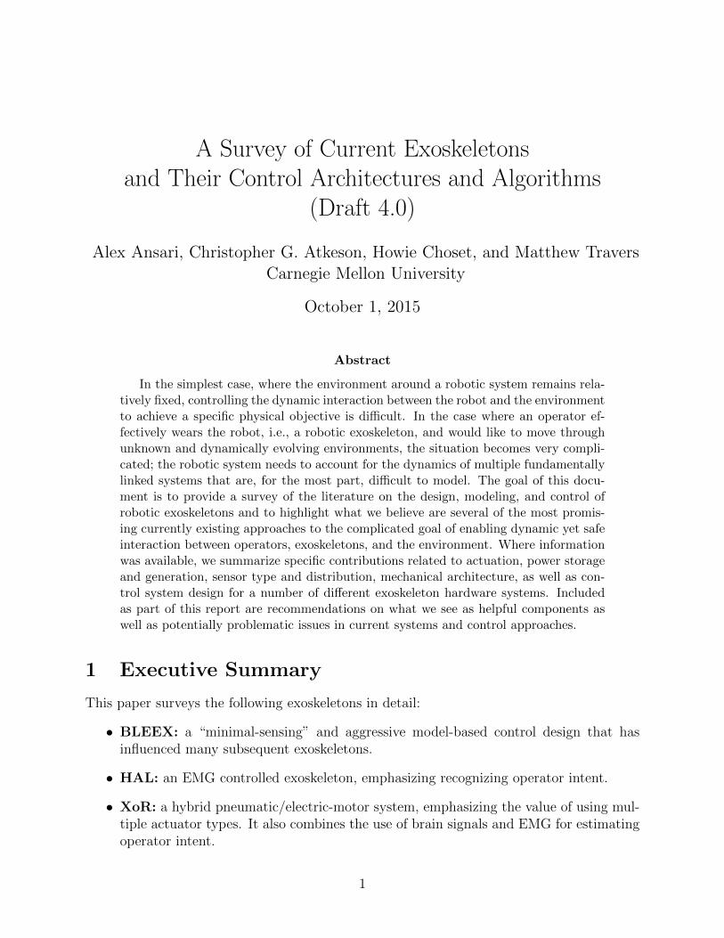
The Berkeley lower extremity exoskeleton (BLEEX) is an anthropomorphic, powered ex-oskeleton designed for human strength augmentation. It is described as the first field-operational robotic system to allow its operator to carry significant loads over unstructuredterrain without external power [3].
The BLEEX system includes two 7 DOF, three-segment legs with thigh, shank, andfoot links, on-board power supply, and a backpack-like frame. The human wearer is rigidlyconnected at the feet and torso such that the frame shelters the user by transferring loadforces to the ground. The leg segments are connected by rotational joints including 3 DOF(2 actuated) at the hip, 1 DOF (actuated) at each knee, and 3 DOF (1 actuated f/e insagittal plane; 2 passive) at the ankles. Joint angles, torque, and power requirements aredetermined from human motion analysis based on a 75-kg human walking on flat ground atroughly 1.3 m/s (the average military male’s maximum reported joint limits are also used toderive joint range of motion targets). During design, joint motion was intended to be slightlyless than the maximum human range of motion for safety; however, some joint ranges hadto be reduced to avoid (mechanical) singularities.
Due to its high power to weight ratio (twice that of electric motors), BLEEX uses ahydraulic actuation system. An on-board internal combustion engine provides both electricand hydraulic power. The joints are driven by commercial small bore (2cm) dual action
3
hydraulic actuators operating at 6.9 MPa. Though the operating pressure is relatively low,the hydraulic actuation system exhibits significant pressures losses across servo valves whenless pressure is required than this system pressure. Table 1 provides details regarding therange of motion and torque capabilities of BLEEX’s joints. As reported in [3], BLEEXrequires 1,143 W for walking relative to 165 W for human walking (14% efficient comparedto a human of the same size). Altogether the suit needs 2.27 kW of hydraulic power and220 W of electric power to accommodate climbing (540 W) and remaining electrical loadsincluding 240 W to power the second stages on servo vales.
3.0.1 Control
The BLEEX team has successfully implemented both sensitivity amplification [2] and ahybrid assistive control scheme [1] that switches (based on gait phase) between sensitivityamplification and a position control regulating desired torque. This section focuses on sen-sitivity amplification, as the hybrid assistive strategy did not perform as well in walkingtrials.
In its sensitivity amplification implementation, BLEEX controllers attempt to minimizeinteraction forces between the human pilot and the exoskeleton. However, the BLEEX team
4
BLEEX human max BLEEXROM torque & power max torque
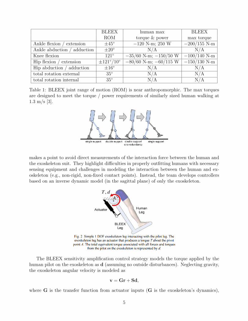
Ankle flexion / extension ±45◦ −120 N-m; 250 W −200/155 N-mAnkle abduction / adduction ±20◦ N/A N/AKnee flexion 121◦ −35/60 N-m; −150/50 W −100/140 N-mHip flexion / extension ±121◦/10◦ −80/60 N-m; −60/115 W −150/130 N-mHip abduction / adduction ±16◦ N/A N/Atotal rotation external 35◦ N/A N/Atotal rotation internal 35◦ N/A N/A
Table 1: BLEEX joint range of motion (ROM) is near anthropomorphic. The max torquesare designed to meet the torque / power requirements of similarly sized human walking at1.3 m/s [3].
makes a point to avoid direct measurements of the interaction force between the human andthe exoskeleton suit. They highlight difficulties in properly outfitting humans with necessarysensing equipment and challenges in modeling the interaction between the human and ex-oskeleton (e.g., non-rigid, non-fixed contact points). Instead, the team develops controllersbased on an inverse dynamic model (in the sagittal plane) of only the exoskeleton.
The BLEEX sensitivity amplification control strategy models the torque applied by thehuman pilot on the exoskeleton as d (assuming no outside disturbances). Neglecting gravity,the exoskeleton angular velocity is modeled as
v = Gr + Sd,
where G is the transfer function from actuator inputs (G is the exoskeleton’s dynamics),
5
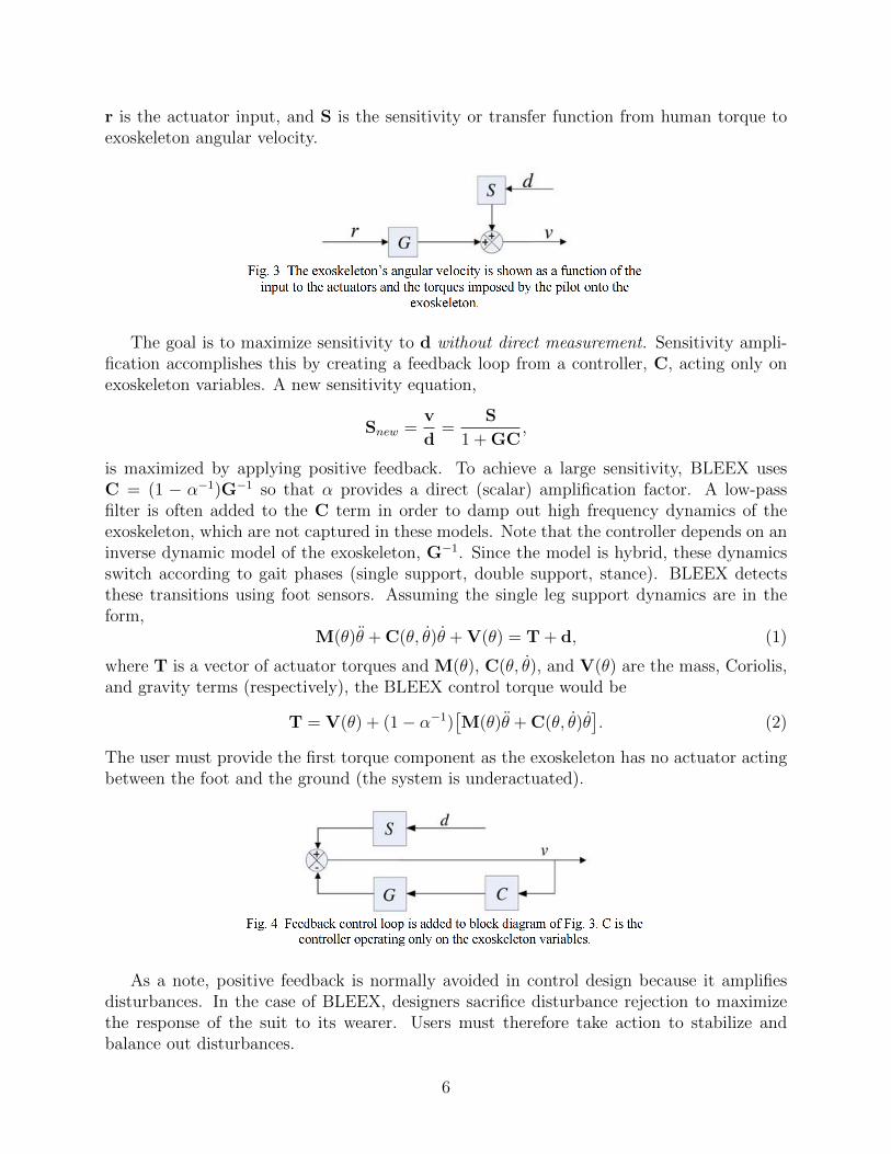
r is the actuator input, and S is the sensitivity or transfer function from human torque toexoskeleton angular velocity.
The goal is to maximize sensitivity to d without direct measurement. Sensitivity ampli-fication accomplishes this by creating a feedback loop from a controller, C, acting only onexoskeleton variables. A new sensitivity equation,
Snew =v
d=
S
1 + GC,
is maximized by applying positive feedback. To achieve a large sensitivity, BLEEX usesC = (1 − α−1)G−1 so that α provides a direct (scalar) amplification factor. A low-passfilter is often added to the C term in order to damp out high frequency dynamics of theexoskeleton, which are not captured in these models. Note that the controller depends on aninverse dynamic model of the exoskeleton, G−1. Since the model is hybrid, these dynamicsswitch according to gait phases (single support, double support, stance). BLEEX detectsthese transitions using foot sensors. Assuming the single leg support dynamics are in theform,
M(θ)θ̈ + C(θ, θ̇)θ̇ + V(θ) = T + d, (1)
where T is a vector of actuator torques and M(θ), C(θ, θ̇), and V(θ) are the mass, Coriolis,and gravity terms (respectively), the BLEEX control torque would be
T = V(θ) + (1 − α−1)[M(θ)θ̈ + C(θ, θ̇)θ̇
]. (2)
The user must provide the first torque component as the exoskeleton has no actuator actingbetween the foot and the ground (the system is underactuated).
As a note, positive feedback is normally avoided in control design because it amplifiesdisturbances. In the case of BLEEX, designers sacrifice disturbance rejection to maximizethe response of the suit to its wearer. Users must therefore take action to stabilize andbalance out disturbances.
6
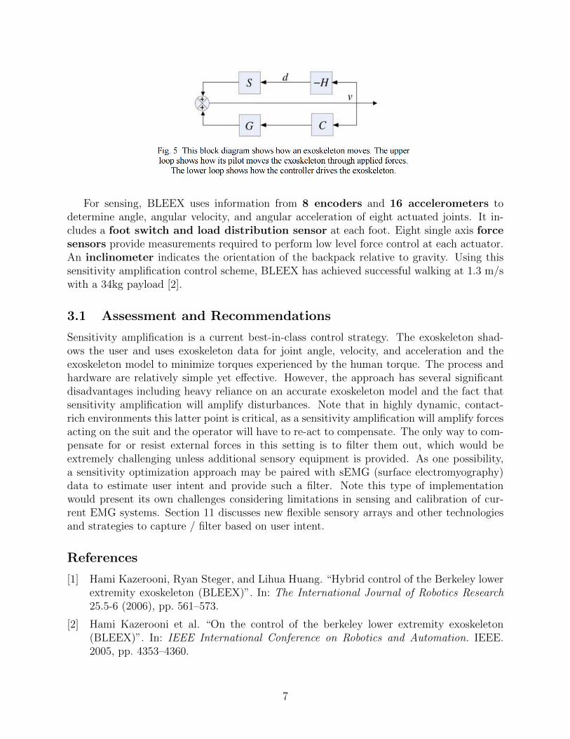
For sensing, BLEEX uses information from 8 encoders and 16 accelerometers todetermine angle, angular velocity, and angular acceleration of eight actuated joints. It in-cludes a foot switch and load distribution sensor at each foot. Eight single axis forcesensors provide measurements required to perform low level force control at each actuator.An inclinometer indicates the orientation of the backpack relative to gravity. Using thissensitivity amplification control scheme, BLEEX has achieved successful walking at 1.3 m/swith a 34kg payload [2].
3.1 Assessment and Recommendations
Sensitivity amplification is a current best-in-class control strategy. The exoskeleton shad-ows the user and uses exoskeleton data for joint angle, velocity, and acceleration and theexoskeleton model to minimize torques experienced by the human torque. The process andhardware are relatively simple yet effective. However, the approach has several significantdisadvantages including heavy reliance on an accurate exoskeleton model and the fact thatsensitivity amplification will amplify disturbances. Note that in highly dynamic, contact-rich environments this latter point is critical, as a sensitivity amplification will amplify forcesacting on the suit and the operator will have to re-act to compensate. The only way to com-pensate for or resist external forces in this setting is to filter them out, which would beextremely challenging unless additional sensory equipment is provided. As one possibility,a sensitivity optimization approach may be paired with sEMG (surface electromyography)data to estimate user intent and provide such a filter. Note this type of implementationwould present its own challenges considering limitations in sensing and calibration of cur-rent EMG systems. Section 11 discusses new flexible sensory arrays and other technologiesand strategies to capture / filter based on user intent.
References
[1] Hami Kazerooni, Ryan Steger, and Lihua Huang. “Hybrid control of the Berkeley lowerextremity exoskeleton (BLEEX)”. In: The International Journal of Robotics Research25.5-6 (2006), pp. 561–573.
[2] Hami Kazerooni et al. “On the control of the berkeley lower extremity exoskeleton(BLEEX)”. In: IEEE International Conference on Robotics and Automation. IEEE.2005, pp. 4353–4360.
7
[3] Adam B Zoss, Hami Kazerooni, and Andrew Chu. “Biomechanical design of the Berkeleylower extremity exoskeleton (BLEEX)”. In: IEEE/ASME Transactions on Mechatronics11.2 (2006), pp. 128–138.
The figures in this section were obtained from [2]. Materials presented are based on thereferences above.
4 HAL
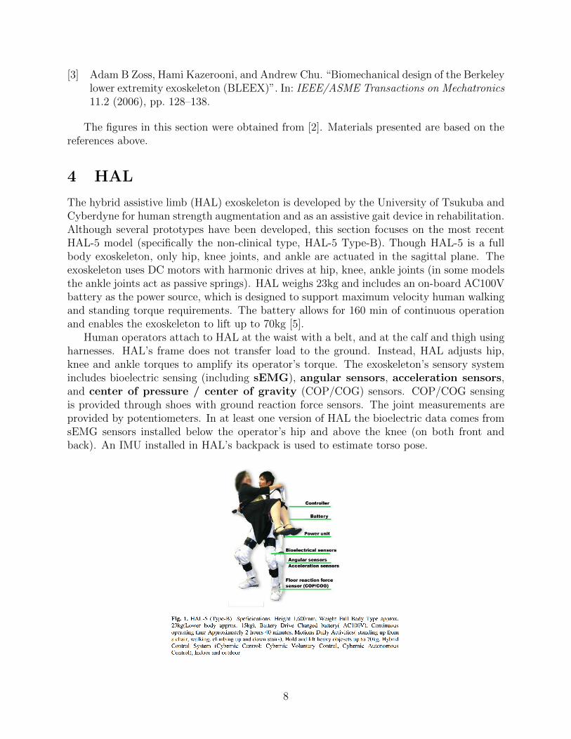
The hybrid assistive limb (HAL) exoskeleton is developed by the University of Tsukuba andCyberdyne for human strength augmentation and as an assistive gait device in rehabilitation.Although several prototypes have been developed, this section focuses on the most recentHAL-5 model (specifically the non-clinical type, HAL-5 Type-B). Though HAL-5 is a fullbody exoskeleton, only hip, knee joints, and ankle are actuated in the sagittal plane. Theexoskeleton uses DC motors with harmonic drives at hip, knee, ankle joints (in some modelsthe ankle joints act as passive springs). HAL weighs 23kg and includes an on-board AC100Vbattery as the power source, which is designed to support maximum velocity human walkingand standing torque requirements. The battery allows for 160 min of continuous operationand enables the exoskeleton to lift up to 70kg [5].
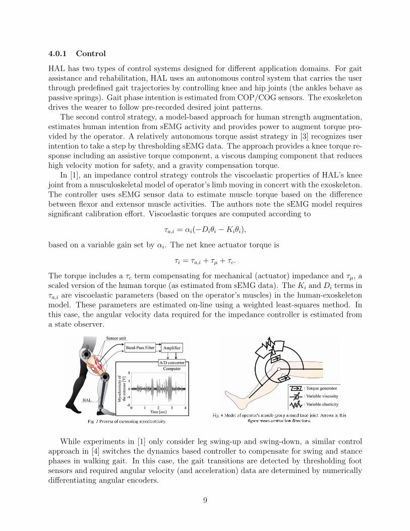
Human operators attach to HAL at the waist with a belt, and at the calf and thigh usingharnesses. HAL’s frame does not transfer load to the ground. Instead, HAL adjusts hip,knee and ankle torques to amplify its operator’s torque. The exoskeleton’s sensory systemincludes bioelectric sensing (including sEMG), angular sensors, acceleration sensors,and center of pressure / center of gravity (COP/COG) sensors. COP/COG sensingis provided through shoes with ground reaction force sensors. The joint measurements areprovided by potentiometers. In at least one version of HAL the bioelectric data comes fromsEMG sensors installed below the operator’s hip and above the knee (on both front andback). An IMU installed in HAL’s backpack is used to estimate torso pose.
8
4.0.1 Control
HAL has two types of control systems designed for different application domains. For gaitassistance and rehabilitation, HAL uses an autonomous control system that carries the userthrough predefined gait trajectories by controlling knee and hip joints (the ankles behave aspassive springs). Gait phase intention is estimated from COP/COG sensors. The exoskeletondrives the wearer to follow pre-recorded desired joint patterns.
The second control strategy, a model-based approach for human strength augmentation,estimates human intention from sEMG activity and provides power to augment torque pro-vided by the operator. A relatively autonomous torque assist strategy in [3] recognizes userintention to take a step by thresholding sEMG data. The approach provides a knee torque re-sponse including an assistive torque component, a viscous damping component that reduceshigh velocity motion for safety, and a gravity compensation torque.
In [1], an impedance control strategy controls the viscoelastic properties of HAL’s kneejoint from a musculoskeletal model of operator’s limb moving in concert with the exoskeleton.The controller uses sEMG sensor data to estimate muscle torque based on the differencebetween flexor and extensor muscle activities. The authors note the sEMG model requiressignificant calibration effort. Viscoelastic torques are computed according to
τa,i = αi(−Diθi −Kiθi),
based on a variable gain set by αi. The net knee actuator torque is
τi = τa,i + τµ + τc.
The torque includes a τc term compensating for mechanical (actuator) impedance and τµ, ascaled version of the human torque (as estimated from sEMG data). The Ki and Di terms inτa,i are viscoelastic parameters (based on the operator’s muscles) in the human-exoskeletonmodel. These parameters are estimated on-line using a weighted least-squares method. Inthis case, the angular velocity data required for the impedance controller is estimated froma state observer.
While experiments in [1] only consider leg swing-up and swing-down, a similar controlapproach in [4] switches the dynamics based controller to compensate for swing and stancephases in walking gait. In this case, the gait transitions are detected by thresholding footsensors and required angular velocity (and acceleration) data are determined by numericallydifferentiating angular encoders.
9
4.1 Assessment and Recommendations
Compared to sensitivity amplification methods, HAL’s use of EMG data allows it to estimateintention without amplifying external disturbances. While direct sensing of user intention isideal for noisy, contract-rich environments, sEMG data is extremely difficult to work withdue to high filtering and calibration requirements. A hybrid strategy which uses sensitivityamplification and sEMG data (possibly thresholded) to filter user intention could prove ef-fective. Additionally, Section 11 mentions new capabilities in nano-fabrication and MEMstechnologies that have produced new high-density, wearable sensing arrays. These and sim-ilarly advanced sensing technology may facilitate direct measurement of interaction forces(i.e. estimating pressure / force and exoskeleton contact locations), which could potentiallyfilter external disturbances from user generated input to estimate intent.
References
[1] Tomohiro Hayashi, Hiroaki Kawamoto, and Yoshiyuki Sankai. “Control method of robotsuit HAL working as operator’s muscle using biological and dynamical information”. In:IEEE/RSJ International Conference on Intelligent Robots and Systems. IEEE. 2005,pp. 3063–3068.
[2] Hiroaki Kawamoto and Yoshiyuki Sankai. “Power assist method based on phase se-quence and muscle force condition for HAL”. In: Advanced Robotics 19.7 (2005), pp. 717–734.
[3] Hiroaki Kawamoto et al. “Voluntary motion support control of Robot Suit HAL trig-gered by bioelectrical signal for hemiplegia”. In: International Conference of the IEEEEngineering in Medicine and Biology Society (EMBC). IEEE. 2010, pp. 462–466.
[4] Suwoong Lee and Yoshiyuki Sankai. “Power assist control for walking aid with HAL-3based on EMG and impedance adjustment around knee joint”. In: IEEE/RSJ Inter-national Conference on Intelligent Robots and Systems. Vol. 2. IEEE. 2002, pp. 1499–1504.
[5] Yoshiyuki Sankai. “HAL: Hybrid assistive limb based on cybernics”. In: Robotics Re-search. Springer, 2011, pp. 25–34.
The figures in this section were obtained from [1, 5]. Materials presented are based onthe references above.
5 XoR
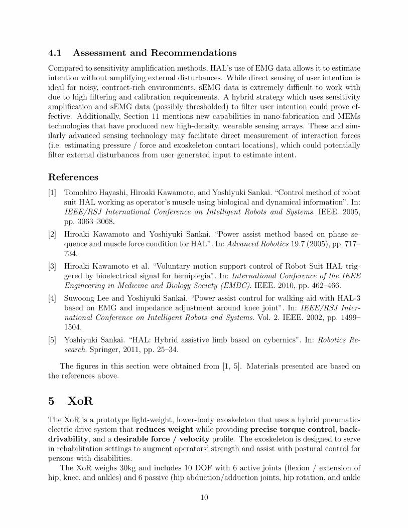
The XoR is a prototype light-weight, lower-body exoskeleton that uses a hybrid pneumatic-electric drive system that reduces weight while providing precise torque control, back-drivability, and a desirable force / velocity profile. The exoskeleton is designed to servein rehabilitation settings to augment operators’ strength and assist with postural control forpersons with disabilities.
The XoR weighs 30kg and includes 10 DOF with 6 active joints (flexion / extension ofhip, knee, and ankles) and 6 passive (hip abduction/adduction joints, hip rotation, and ankle
10
adduction/abduction). The active joints are powered by hybrid actuators comprised ofan air muscle and an electric motor. The hybrid actuation scheme uses a unilateral airmuscle layout to compensate for gravity and bilateral electric motors with a relatively smallgear ratio (57.5) to serve as the dynamic compensator.
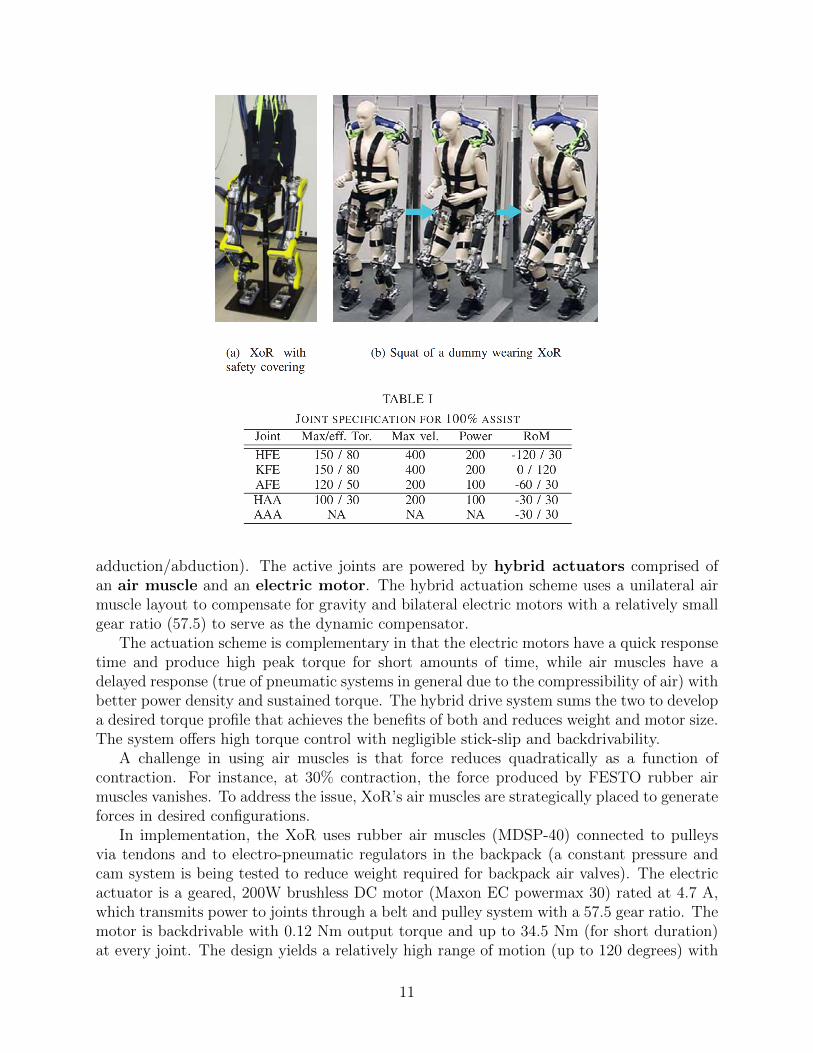
The actuation scheme is complementary in that the electric motors have a quick responsetime and produce high peak torque for short amounts of time, while air muscles have adelayed response (true of pneumatic systems in general due to the compressibility of air) withbetter power density and sustained torque. The hybrid drive system sums the two to developa desired torque profile that achieves the benefits of both and reduces weight and motor size.The system offers high torque control with negligible stick-slip and backdrivability.
A challenge in using air muscles is that force reduces quadratically as a function ofcontraction. For instance, at 30% contraction, the force produced by FESTO rubber airmuscles vanishes. To address the issue, XoR’s air muscles are strategically placed to generateforces in desired configurations.
In implementation, the XoR uses rubber air muscles (MDSP-40) connected to pulleysvia tendons and to electro-pneumatic regulators in the backpack (a constant pressure andcam system is being tested to reduce weight required for backpack air valves). The electricactuator is a geared, 200W brushless DC motor (Maxon EC powermax 30) rated at 4.7 A,which transmits power to joints through a belt and pulley system with a 57.5 gear ratio. Themotor is backdrivable with 0.12 Nm output torque and up to 34.5 Nm (for short duration)at every joint. The design yields a relatively high range of motion (up to 120 degrees) with
11
a 150 Nm load capacity. However, experiments reveal the need for bi-directional pneumaticactuation at hip joints.
For sensing, XoR is equipped with rotary encoders at joints, an IMU in the backpack,load cells in the feet, and is networked to servers capable of providing EMG, NIRS (near-infrared spectroscopy), and EEG (electroencephalogram) data. A control PC running at 1KHz, pulse counter, amplifiers, Digital IO are external and so not included in the weight ofthe unit. Human operators are outfitted with a goniometer.
5.0.1 Control
The XoR control strategy applied in [2] has two main components. First, a proportional-derivative (PD) feedback controller tracks desired joint angles and angular velocities thatcorrespond to the state of the exoskeleton required to assist the human operator. To obtainthis state (specifying the desired joint angles / velocities), the controller simultaneously mea-sures the joint angle trajectories of the human user (goniometer) and of the robot (encoders),and uses canonical correlation analysis (CCA) to extract latent variables in the kinematicrelationship between the two.
To avoid relying on high gain feedback, XoR incorporates user intent through EMGdata. The controller rectifies and low pass filters (10 Hz cut-off) data measured in the pilot’squadriceps femoris, tensor fasciae latate, gluteus medius, and tibialis anterior. It sets desiredjoint angles and velocities, x = (θ, θ̇), from the EMG data, u = (EMG1, . . . , EMGn), usinga linear prediction model,
x(k + 1) = Ax(k) + Bu(k),
12
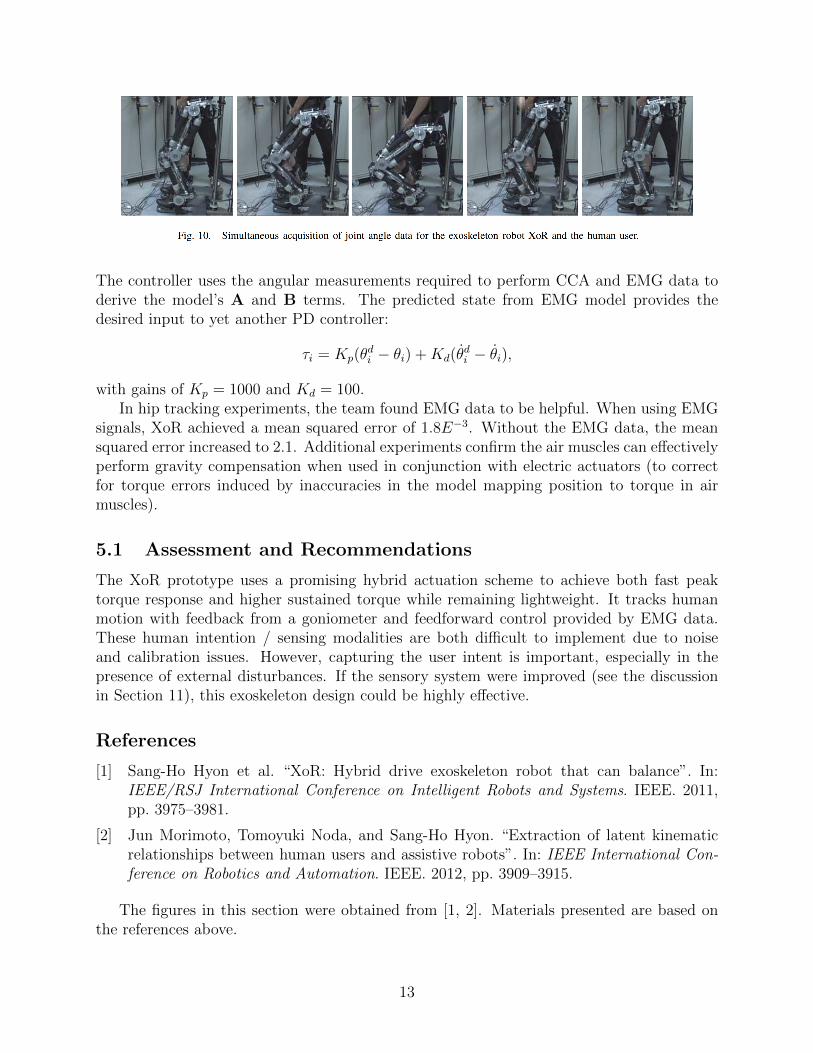
The controller uses the angular measurements required to perform CCA and EMG data toderive the model’s A and B terms. The predicted state from EMG model provides thedesired input to yet another PD controller:
τi = Kp(θdi − θi) +Kd(θ̇
di − θ̇i),
with gains of Kp = 1000 and Kd = 100.In hip tracking experiments, the team found EMG data to be helpful. When using EMG
signals, XoR achieved a mean squared error of 1.8E−3. Without the EMG data, the meansquared error increased to 2.1. Additional experiments confirm the air muscles can effectivelyperform gravity compensation when used in conjunction with electric actuators (to correctfor torque errors induced by inaccuracies in the model mapping position to torque in airmuscles).
5.1 Assessment and Recommendations
The XoR prototype uses a promising hybrid actuation scheme to achieve both fast peaktorque response and higher sustained torque while remaining lightweight. It tracks humanmotion with feedback from a goniometer and feedforward control provided by EMG data.These human intention / sensing modalities are both difficult to implement due to noiseand calibration issues. However, capturing the user intent is important, especially in thepresence of external disturbances. If the sensory system were improved (see the discussionin Section 11), this exoskeleton design could be highly effective.
References
[1] Sang-Ho Hyon et al. “XoR: Hybrid drive exoskeleton robot that can balance”. In:IEEE/RSJ International Conference on Intelligent Robots and Systems. IEEE. 2011,pp. 3975–3981.
[2] Jun Morimoto, Tomoyuki Noda, and Sang-Ho Hyon. “Extraction of latent kinematicrelationships between human users and assistive robots”. In: IEEE International Con-ference on Robotics and Automation. IEEE. 2012, pp. 3909–3915.
The figures in this section were obtained from [1, 2]. Materials presented are based onthe references above.
13
6 Body Extender
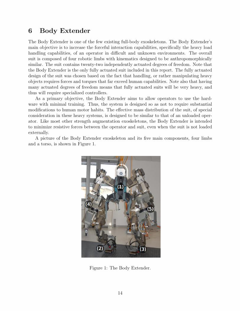
The Body Extender is one of the few existing full-body exoskeletons. The Body Extender’smain objective is to increase the forceful interaction capabilities, specifically the heavy loadhandling capabilities, of an operator in difficult and unknown environments. The overallsuit is composed of four robotic limbs with kinematics designed to be anthropomorphicallysimilar. The suit contains twenty-two independently actuated degrees of freedom. Note thatthe Body Extender is the only fully actuated suit included in this report. The fully actuateddesign of the suit was chosen based on the fact that handling, or rather manipulating heavyobjects requires forces and torques that far exceed human capabilities. Note also that havingmany actuated degrees of freedom means that fully actuated suits will be very heavy, andthus will require specialized controllers.
As a primary objective, the Body Extender aims to allow operators to use the hard-ware with minimal training. Thus, the system is designed so as not to require substantialmodifications to human motor habits. The effective mass distribution of the suit, of specialconsideration in these heavy systems, is designed to be similar to that of an unloaded oper-ator. Like most other strength augmentation exoskeletons, the Body Extender is intendedto minimize resistive forces between the operator and suit, even when the suit is not loadedexternally.
A picture of the Body Extender exoskeleton and its five main components, four limbsand a torso, is shown in Figure 1.
Figure 1: The Body Extender.
14
6.1 Actuator Specifications
Except for forearm pronosupination, each of the actuators in the Body Extender suit aredriven by a linear actuator that is composed of an electrical motor, incremental encoder, ballscrew, and angular contact ball bearings. The motors are frame-less DC torque controlledmotors. The peak torque of the motors is 7 Nm, with a maximum continuoustorque of 6 Nm. Each motor weighs 1.4 kg. The linear actuator assembly is able tosupply 8000 N with a total weight of 2.4 kg.
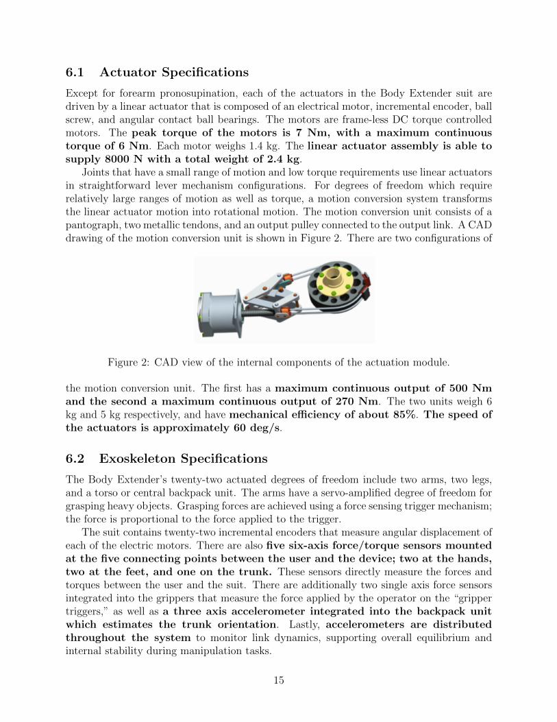
Joints that have a small range of motion and low torque requirements use linear actuatorsin straightforward lever mechanism configurations. For degrees of freedom which requirerelatively large ranges of motion as well as torque, a motion conversion system transformsthe linear actuator motion into rotational motion. The motion conversion unit consists of apantograph, two metallic tendons, and an output pulley connected to the output link. A CADdrawing of the motion conversion unit is shown in Figure 2. There are two configurations of
Figure 2: CAD view of the internal components of the actuation module.
the motion conversion unit. The first has a maximum continuous output of 500 Nmand the second a maximum continuous output of 270 Nm. The two units weigh 6kg and 5 kg respectively, and have mechanical efficiency of about 85%. The speed ofthe actuators is approximately 60 deg/s.
6.2 Exoskeleton Specifications
The Body Extender’s twenty-two actuated degrees of freedom include two arms, two legs,and a torso or central backpack unit. The arms have a servo-amplified degree of freedom forgrasping heavy objects. Grasping forces are achieved using a force sensing trigger mechanism;the force is proportional to the force applied to the trigger.
The suit contains twenty-two incremental encoders that measure angular displacement ofeach of the electric motors. There are also five six-axis force/torque sensors mountedat the five connecting points between the user and the device; two at the hands,two at the feet, and one on the trunk. These sensors directly measure the forces andtorques between the user and the suit. There are additionally two single axis force sensorsintegrated into the grippers that measure the force applied by the operator on the “grippertriggers,” as well as a three axis accelerometer integrated into the backpack unitwhich estimates the trunk orientation. Lastly, accelerometers are distributedthroughout the system to monitor link dynamics, supporting overall equilibrium andinternal stability during manipulation tasks.
15

The control software is distributed between a central processing unit andsixteen local units located throughout the system. The communication betweenprocessing units is handled using a high-speed field bus.
The system is powered using thirteen batteries in series, which provide anominal voltage of 78 V. When the system is run in stand-alone mode, the batteries canprovide eight hours of continuous work.
6.3 Control Specifications
The body extender control algorithm centers around a feedback linearization policy thatdepends on measuring the force between the operator and suit, knowing the contact stateof the suit and environment, decoupling the control of each of the limbs for each other, andhaving each limb be fully actuated. The dynamics for each of the Body Extender limbs arewritten in standard form as
Bi(q)q̈ + Ci(q, q̇)q̇ + Gi(q) = τ + JTiuFs + JTiaFa, (3)
where i is an integer corresponding to a different limb, τ represents the actuator torques, Fs
the measured forces between the operator and suit, and Fa the unmeasured contact forceson the suit. The Bi, Ci, and Gi terms represent the limb inertia, Coriolis and centrifugal,and gravitational torques.
The authors in [2] use a decoupling strategy in their controllers which enables the indi-vidual limbs in the Body Extender to be somewhat decoupled from each other. They claimthat they accomplish this using the following model:
Bi(q)q̈ + Ci(q, q̇)q̇ + GiT (q) = τ + JTiuFs + JTiaFa − BiT qV̇T − CiT (q, q̇)VT, (4)
where, VT is the trunk velocity, GiT the gravitational effect of the trunk on the limb, BiT
the inertia of the trunk acting on the limb, and CiT the trunk Coriolis and centrifugal term.Note that VT and V̇T are directly measured through the accelerometer and gyroscope inthe trunk.
The feedback linearizing controller in operates under two fundamental assumptions andonly appears to relate directly to the case of a single manipulator arm. The first assumptionof the controller is that the mass and inertial properties of an object being manipulated areestimated online. The second is that the forces measured between the operator and suit canbe modeled as
Fs = MpV̇e + Gp, (5)
where Mp is an effective mass of the end effector, V̇e is the acceleration of the end effector,and Gp is an effective gravitational term. Note that the gravitational term is zero if the armis not holding an external load. The importance of these two assumptions will be more clearafter the analytical forms of the feedback linearizing controllers are introduced.
The dynamics of the arm when not manipulating a load are
B(q)q̈ + C(q, q̇)q̇ + G(q) = τ.
The feedback linearizing controller for this case has the form
τ = B(q)(q̈d +Kv ˙̃q +Kp˜q) + C(q, q̇)q̇ + G(q),
16

where ˜q = qd − q. The details are unclear in [2], but it appears that the authors eitherpropose using predefined trajectories to define q̈d, q̇d, and qd, or use the assumption in (5)to determine these values. Equation 5 relates the measured force to the derivative of theend effector velocity V̇e. This end effector velocity can then be related to the desired jointvelocities using the analytical Jacobian transformation
q̈d = J(q)−1(V̇e − J̇(q, q̇)q̇).
The values for q̇d and qd can then be found through integration. It is not clear the howauthors explicitly decouple the human dynamics from the robot in this case.
In the case where the exoskeleton arm is manipulating a load, the feedback linearizingcontroller has the augmented form
τ = B(q)(q̈d +Kv ˙̃q +Kp˜q) + C(q, q̇)q̇ + G(q) − JT (q)Fs − JT (q)Fa.
The main difference in this case is that the controller here explicitly compensates for themeasured human-robot interaction force Fs, and the controller includes the un-sensed forcesFa which arise from the object being manipulated. The object interaction forces thus needto be estimated. The ability to estimate these forces is the first fundamental assumption onwhich the Body Extender’s control scheme relies. Because the point at which the manipulatorarm and object are connected is assumed to be well known, and the arm is instrumented withinertial sensors, estimating the interaction forces of the manipulated object is be assumedto be equivalent to estimating its inertial properties. As outlined in [2], this is accomplishedusing a standard regressor which uses the input and output of the feedback linearizingcontroller as the basis for the regression. The details of this process are left to [2].
6.4 Assessment and Recommendations
The Body Extender suit is one of the only fully-actuated upper and lower extremity ex-oskeletons available today. Clearly, for the task of handling extremely heavy objects, a fullyactuated suit may be the best option, but, generally speaking, having the additional weightdue to actuating every degree of freedom in the suit is not ideal when considering dynamicoperation.
The controllers highlighted in [2] do present some novel components. For example, usinga regressor to estimate unknown external forces may be an idea which is directly applicable toa variety of different projects. Note that in the case of the Body Extender, this regression isdependent on knowing the location of the external force relative to the suit, the manipulatorend effectors. Thus, an extension of this idea, possibly using a lager distribution of sensorsto measure external forces, is necessary to extend this approach more generally.
The way that the Body Extender control uses operator-robot measured interaction forcesto generate desired trajectories around which a stabilizing controller is designed is generallyan idea that we support. Note that, like any of the model-based control approaches outlinedin the exoskeleton literature the feedback linearizing controller in this work is dependent onknowing the model of the robot hardware with a relatively high-level of fidelity.
In terms of the controlling of the overall suit, i.e., locomotion in addition to manipulation,it was difficult to find any papers that discussed more than upper-body single-arm control
17
of a manipulated object for the Body Extender hardware. The stated strategy of decouplingthe individual limbs from each other seems somewhat feasible, but is limited relative tocoordinated limb control.
The speed of the actuators (approximately 60 deg/s) is far to slow for dynamic humanmovement.
The mechanical specifications as well as figures related to mechanical design for the BodyExtender system discussed in this section are based on and taken from [1]. The discussionof the control system is based on work presented in [2].
References
[1] S. Marcheschi et al. “Body Extender: Whole body exoskeleton for human power aug-mentation”. In: Proc. IEEE Int. Conf. Robotics Automation. IEEE. 2011, pp. 611–616.
[2] G.P. Rosati Papini and C.A. Avizzano. “Transparent Force Control for Body Exten-der”. In: The 21st IEEE International Symposium on Robot and Human InteractiveCommunication. IEEE. 2012, pp. 138–143.
7 Hydraulic Lower Extremity Exoskeleton
The Hydraulic Lower Extremity Exoskeleton suit was originally developed for military uses,specifically to allow operators to perform motions without incurring muscle fatigue. Theexoskeleton uses a new virtual joint torque control approach, which has been shownto be effective for controlling human robot interaction in situations where the connectionsbetween the users and hardware system are relatively unknown or can dramatically changeas a function of time.
Additionally, the main hardware design principle is focused on developing a suit that canaugment user power and yet move fast when necessary. The design team selected hydraulicactuators because the weight of electric actuators on leg joints would make the systemdifficult to move quickly. Hydraulic actuators have high power density relative to weightand size and generally provide very high force outputs and low impedance. As a trade-off,hydraulics have reduced accuracy in terms of force control and it is difficult to model theirnonlinear characteristics.
A picture of the Hydraulic Lower Extremity Exoskeleton is presented in Figure 3.
7.1 Actuator specifications
The Hydraulic Lower Extremity Exoskeleton’s actuators were designed based on humanwalking data obtained at 4 km/h with a 45 kg load. Based on this data, the hydrauliccapacity system was designed to provide 2050 psi and 8 LPM. The individual actuators weredesigned to be double acting at the hip and knee flexion/extension joints. They provide ahip maximum thrust of 4 kN and knee maximum thrust of 4 kN. Each joint jointincludes three-way servo valves (M 200, Star-Hydraulic) to control rate and direction ofbi-directionality, and bypass valves to connect the pump path to tank path for fast, energy-efficient motion during swing phases.
18

Figure 3: Exoskeleton robot system.
The hydraulic system for each joint is shown in Figure 4. A picture of the HydraulicLower Extremity Exoskeleton is presented in Figure 3.
Figure 4: Dual-mode control
7.2 Exoskeleton Specifications
The Hydraulic Lower Extremity Exoskeleton includes four actively controlled joints in thesagittal plane, with powered knee and hip flexion/extension. The eight passive joints includeone ab/adduction DOF for each hip and 3 DOF for each ankle.
The hydraulic system is composed of the four actuators and a hydraulic power unit,consisting of a pump, motor, temperature sensor, and various valves.
On-board sensors measure joint angles, actuator forces, and ground reaction forces.Three absolute angular encoders are incorporated at the hip, knee, and ankle pitch joints.In-line load cells are incorporated in each cylinder tube to measure actuator forces, andfour single axis load cells are included in foot sensors to be used for gait phase detection.
19
7.3 Control Specifications
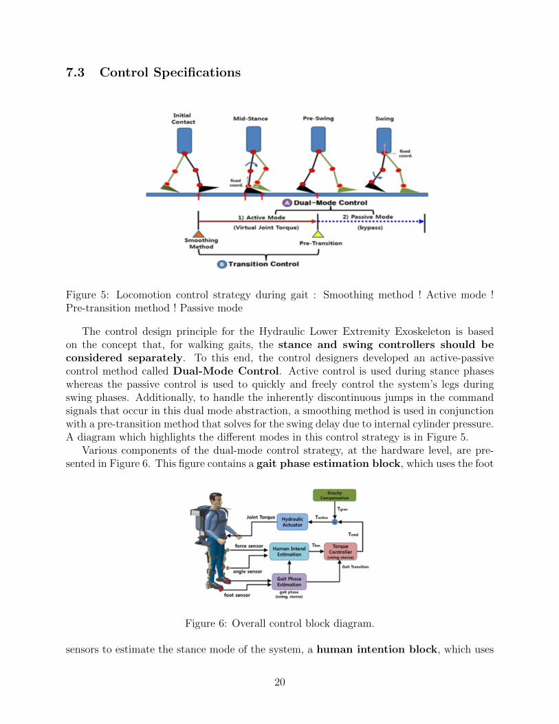
Figure 5: Locomotion control strategy during gait : Smoothing method ! Active mode !Pre-transition method ! Passive mode
The control design principle for the Hydraulic Lower Extremity Exoskeleton is basedon the concept that, for walking gaits, the stance and swing controllers should beconsidered separately. To this end, the control designers developed an active-passivecontrol method called Dual-Mode Control. Active control is used during stance phaseswhereas the passive control is used to quickly and freely control the system’s legs duringswing phases. Additionally, to handle the inherently discontinuous jumps in the commandsignals that occur in this dual mode abstraction, a smoothing method is used in conjunctionwith a pre-transition method that solves for the swing delay due to internal cylinder pressure.A diagram which highlights the different modes in this control strategy is in Figure 5.
Various components of the dual-mode control strategy, at the hardware level, are pre-sented in Figure 6. This figure contains a gait phase estimation block, which uses the foot
Figure 6: Overall control block diagram.
sensors to estimate the stance mode of the system, a human intention block, which uses
20
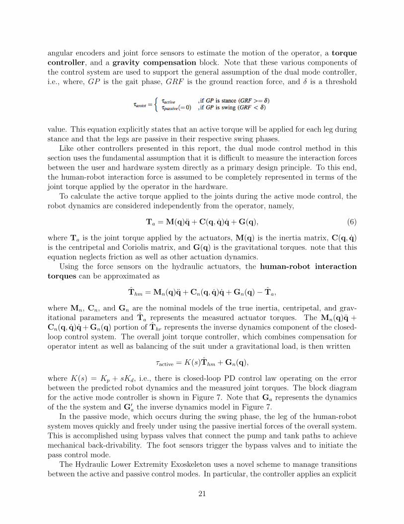
angular encoders and joint force sensors to estimate the motion of the operator, a torquecontroller, and a gravity compensation block. Note that these various components ofthe control system are used to support the general assumption of the dual mode controller,i.e., where, GP is the gait phase, GRF is the ground reaction force, and δ is a threshold
value. This equation explicitly states that an active torque will be applied for each leg duringstance and that the legs are passive in their respective swing phases.
Like other controllers presented in this report, the dual mode control method in thissection uses the fundamental assumption that it is difficult to measure the interaction forcesbetween the user and hardware system directly as a primary design principle. To this end,the human-robot interaction force is assumed to be completely represented in terms of thejoint torque applied by the operator in the hardware.
To calculate the active torque applied to the joints during the active mode control, therobot dynamics are considered independently from the operator, namely,
Ta = M(q)q̈ + C(q, q̇)q̇ + G(q), (6)
where Ta is the joint torque applied by the actuators, M(q) is the inertia matrix, C(q, q̇)is the centripetal and Coriolis matrix, and G(q) is the gravitational torques. note that thisequation neglects friction as well as other actuation dynamics.
Using the force sensors on the hydraulic actuators, the human-robot interactiontorques can be approximated as
T̂hm = Mn(q)q̈ + Cn(q, q̇)q̇ + Gn(q) − T̂a,
where Mn, Cn, and Gn are the nominal models of the true inertia, centripetal, and grav-itational parameters and T̂a represents the measured actuator torques. The Mn(q)q̈ +Cn(q, q̇)q̇ + Gn(q) portion of T̂hr represents the inverse dynamics component of the closed-loop control system. The overall joint torque controller, which combines compensation foroperator intent as well as balancing of the suit under a gravitational load, is then written
τactive = K(s)T̂hm + Gn(q),
where K(s) = Kp + sKd, i.e., there is closed-loop PD control law operating on the errorbetween the predicted robot dynamics and the measured joint torques. The block diagramfor the active mode controller is shown in Figure 7. Note that Ga represents the dynamicsof the the system and G′a the inverse dynamics model in Figure 7.
In the passive mode, which occurs during the swing phase, the leg of the human-robotsystem moves quickly and freely under using the passive inertial forces of the overall system.This is accomplished using bypass valves that connect the pump and tank paths to achievemechanical back-drivability. The foot sensors trigger the bypass valves and to initiate thepass control mode.
The Hydraulic Lower Extremity Exoskeleton uses a novel scheme to manage transitionsbetween the active and passive control modes. In particular, the controller applies an explicit
21
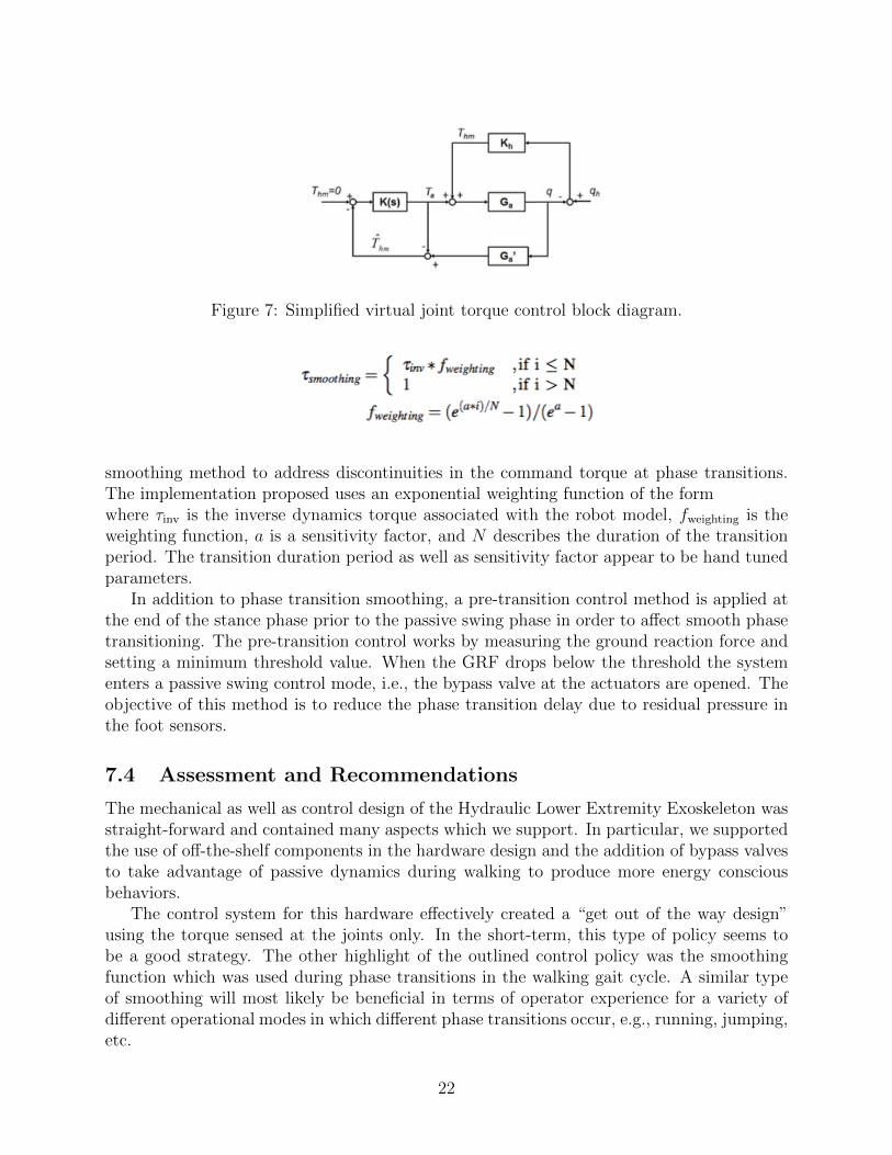
Figure 7: Simplified virtual joint torque control block diagram.
smoothing method to address discontinuities in the command torque at phase transitions.The implementation proposed uses an exponential weighting function of the formwhere τinv is the inverse dynamics torque associated with the robot model, fweighting is theweighting function, a is a sensitivity factor, and N describes the duration of the transitionperiod. The transition duration period as well as sensitivity factor appear to be hand tunedparameters.
In addition to phase transition smoothing, a pre-transition control method is applied atthe end of the stance phase prior to the passive swing phase in order to affect smooth phasetransitioning. The pre-transition control works by measuring the ground reaction force andsetting a minimum threshold value. When the GRF drops below the threshold the systementers a passive swing control mode, i.e., the bypass valve at the actuators are opened. Theobjective of this method is to reduce the phase transition delay due to residual pressure inthe foot sensors.
7.4 Assessment and Recommendations
The mechanical as well as control design of the Hydraulic Lower Extremity Exoskeleton wasstraight-forward and contained many aspects which we support. In particular, we supportedthe use of off-the-shelf components in the hardware design and the addition of bypass valvesto take advantage of passive dynamics during walking to produce more energy consciousbehaviors.
The control system for this hardware effectively created a “get out of the way design”using the torque sensed at the joints only. In the short-term, this type of policy seems tobe a good strategy. The other highlight of the outlined control policy was the smoothingfunction which was used during phase transitions in the walking gait cycle. A similar typeof smoothing will most likely be beneficial in terms of operator experience for a variety ofdifferent operational modes in which different phase transitions occur, e.g., running, jumping,etc.
22
One potential drawback of this hardware is the power system. The documentation in [1]was sparse with respect to the exact specifications of the motor and energy storage devicewhich powers the hydraulic system. Additionally, in the long-term control design strategy,pure get out of the way control using measurements of the suit only has drawbacks, asmentioned previously. This strategy will ultimately lead to a “sensitivity amplification” -like behavior. This strategy will thus be positively sensitive to user intended motion andnegatively sensitive to external disturbances.
The figures as well as hardware and control specifications in this section are taken from[1].
References
[1] Hongchul Kim et al. “Locomotion Control Strategy of Hydraulic Lower Extremity Ex-oskeleton Robot”. In: IEEE International Conference on Advanced Intelligent Mecha-tronics. IEEE, 2015, pp. 577–582.
8 IHMC Mobility Assist Exoskeleton (MAE)
Although the IHMC MAE was primarily designed as a disabled assist exoskeleton, the devicealso provides a “performance enhancement” control mode, which is within the scope of thisdocument. The main design principle highlighted in the IHMC MAE hardware (a recurringtheme throughout the exoskeleton literature) is that directly measuring user intent can bedifficult for a number of reasons. The IHMC designers resolve the issue using a new controland feedback system, which for the IHMC MAE, is primarily based on a unique actuationscheme.
The IHMC MAE uses novel series elastic actuators (SEAs) in their hardware designmostly because they offer the ability to perform high-fidelity impedance control. In serieselastic actuators, a compliant element is placed in series after the output a motor’s drivemechanism. The measured compression of the compliant element is used to calculate theforce, or torque, acting on the output of the actuator. Series elastic actuators aregenerally viewed as a good way to provide accurate force feedback information and toprovide a low mechanical impedance. The major disadvantage of SEAs is that they havea relatively low bandwidth at high forces, as the compliant element needs time to compressbefore a force can be sensed and thus inherently include a delay between the time a force isapplied and when the control system can react.
8.1 Actuator specifications
The IHMC actuators are designed based on data collected from clinical gait analysis. Specif-ically, the actuators at the hip and knee were designed to be able to provide 40Nm of peaktorque during the stance phase of the walking gait cycle. The rotary SEA is composed of aMoog BN34-25EU-02 brushless DC motor with a 1:100 harmonic drive (SHD-20).
The spring mechanism, which sits between the gearbox and joint output, is shown inFigure 8. The mechanism uses linear die springs and an angular encoder to measure the
23
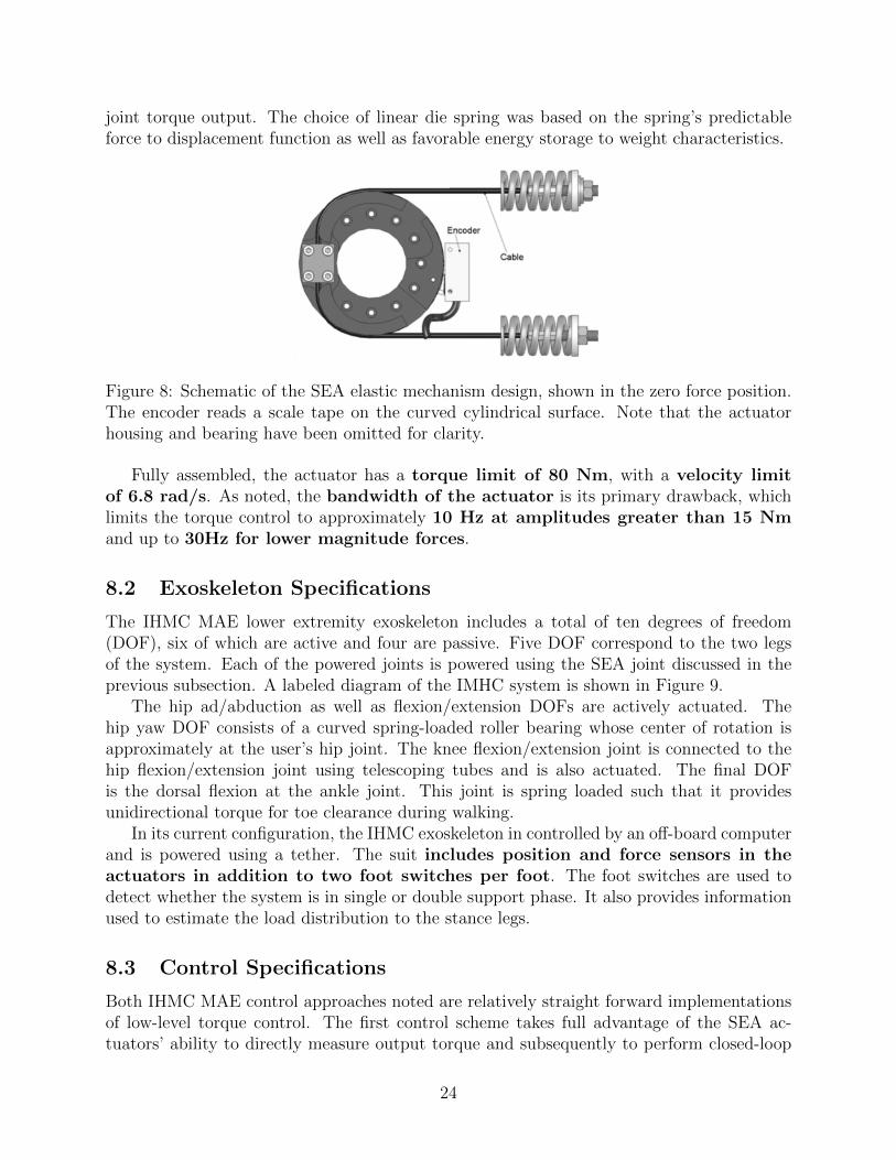
joint torque output. The choice of linear die spring was based on the spring’s predictableforce to displacement function as well as favorable energy storage to weight characteristics.
Figure 8: Schematic of the SEA elastic mechanism design, shown in the zero force position.The encoder reads a scale tape on the curved cylindrical surface. Note that the actuatorhousing and bearing have been omitted for clarity.
Fully assembled, the actuator has a torque limit of 80 Nm, with a velocity limitof 6.8 rad/s. As noted, the bandwidth of the actuator is its primary drawback, whichlimits the torque control to approximately 10 Hz at amplitudes greater than 15 Nmand up to 30Hz for lower magnitude forces.
8.2 Exoskeleton Specifications
The IHMC MAE lower extremity exoskeleton includes a total of ten degrees of freedom(DOF), six of which are active and four are passive. Five DOF correspond to the two legsof the system. Each of the powered joints is powered using the SEA joint discussed in theprevious subsection. A labeled diagram of the IMHC system is shown in Figure 9.
The hip ad/abduction as well as flexion/extension DOFs are actively actuated. Thehip yaw DOF consists of a curved spring-loaded roller bearing whose center of rotation isapproximately at the user’s hip joint. The knee flexion/extension joint is connected to thehip flexion/extension joint using telescoping tubes and is also actuated. The final DOFis the dorsal flexion at the ankle joint. This joint is spring loaded such that it providesunidirectional torque for toe clearance during walking.
In its current configuration, the IHMC exoskeleton in controlled by an off-board computerand is powered using a tether. The suit includes position and force sensors in theactuators in addition to two foot switches per foot. The foot switches are used todetect whether the system is in single or double support phase. It also provides informationused to estimate the load distribution to the stance legs.
8.3 Control Specifications
Both IHMC MAE control approaches noted are relatively straight forward implementationsof low-level torque control. The first control scheme takes full advantage of the SEA ac-tuators’ ability to directly measure output torque and subsequently to perform closed-loop
24
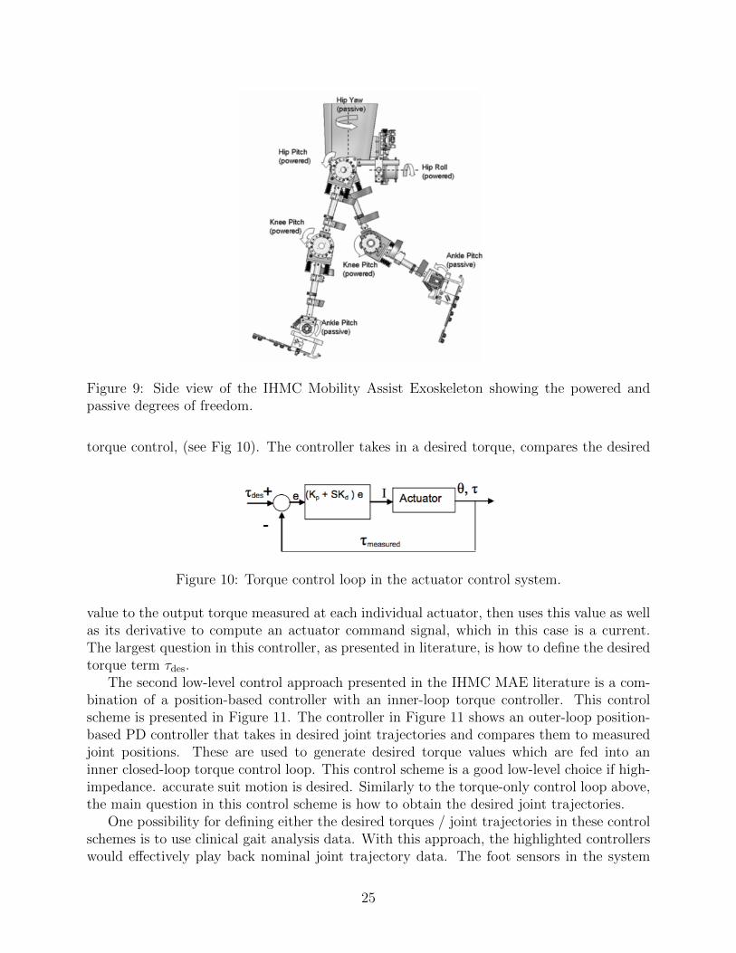
Figure 9: Side view of the IHMC Mobility Assist Exoskeleton showing the powered andpassive degrees of freedom.
torque control, (see Fig 10). The controller takes in a desired torque, compares the desired
Figure 10: Torque control loop in the actuator control system.
value to the output torque measured at each individual actuator, then uses this value as wellas its derivative to compute an actuator command signal, which in this case is a current.The largest question in this controller, as presented in literature, is how to define the desiredtorque term τdes.
The second low-level control approach presented in the IHMC MAE literature is a com-bination of a position-based controller with an inner-loop torque controller. This controlscheme is presented in Figure 11. The controller in Figure 11 shows an outer-loop position-based PD controller that takes in desired joint trajectories and compares them to measuredjoint positions. These are used to generate desired torque values which are fed into aninner closed-loop torque control loop. This control scheme is a good low-level choice if high-impedance. accurate suit motion is desired. Similarly to the torque-only control loop above,the main question in this control scheme is how to obtain the desired joint trajectories.
One possibility for defining either the desired torques / joint trajectories in these controlschemes is to use clinical gait analysis data. With this approach, the highlighted controllerswould effectively play back nominal joint trajectory data. The foot sensors in the system
25
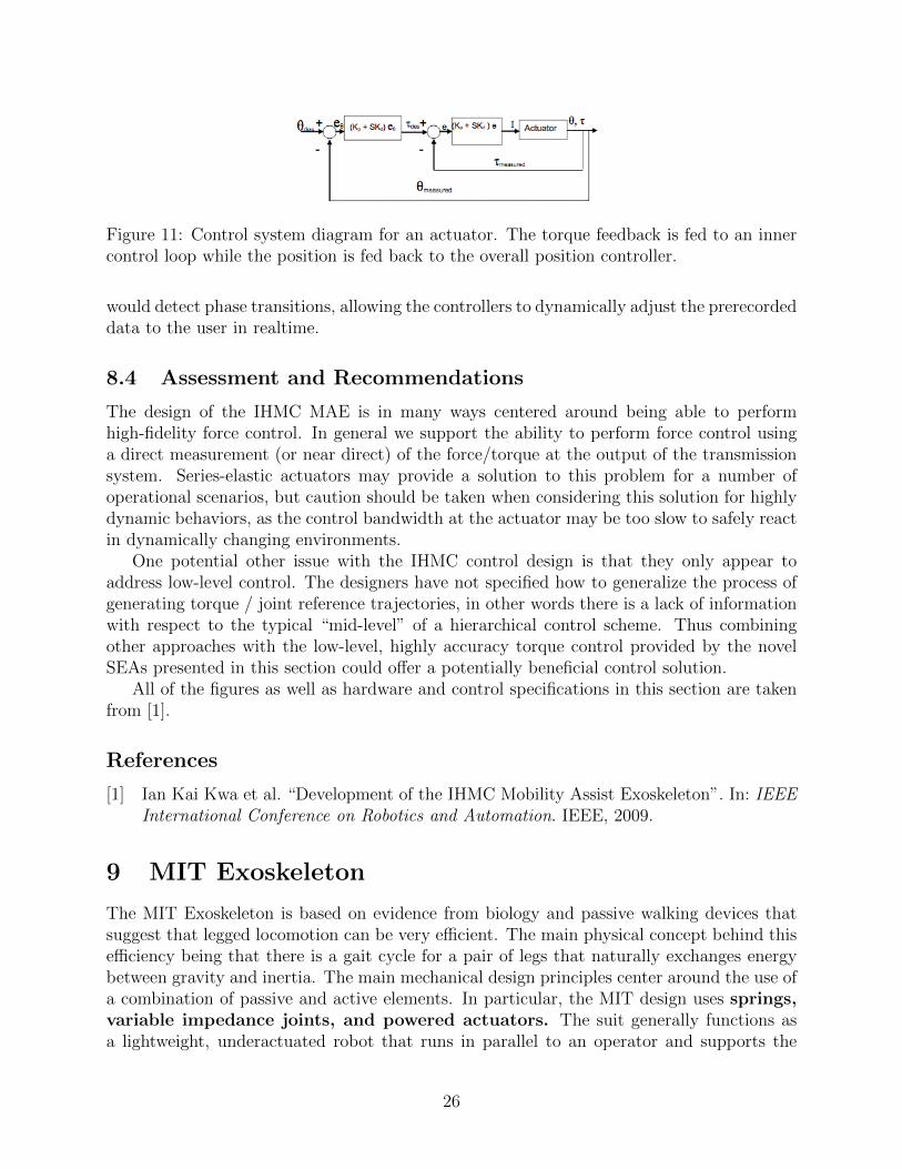
Figure 11: Control system diagram for an actuator. The torque feedback is fed to an innercontrol loop while the position is fed back to the overall position controller.
would detect phase transitions, allowing the controllers to dynamically adjust the prerecordeddata to the user in realtime.
8.4 Assessment and Recommendations
The design of the IHMC MAE is in many ways centered around being able to performhigh-fidelity force control. In general we support the ability to perform force control usinga direct measurement (or near direct) of the force/torque at the output of the transmissionsystem. Series-elastic actuators may provide a solution to this problem for a number ofoperational scenarios, but caution should be taken when considering this solution for highlydynamic behaviors, as the control bandwidth at the actuator may be too slow to safely reactin dynamically changing environments.
One potential other issue with the IHMC control design is that they only appear toaddress low-level control. The designers have not specified how to generalize the process ofgenerating torque / joint reference trajectories, in other words there is a lack of informationwith respect to the typical “mid-level” of a hierarchical control scheme. Thus combiningother approaches with the low-level, highly accuracy torque control provided by the novelSEAs presented in this section could offer a potentially beneficial control solution.
All of the figures as well as hardware and control specifications in this section are takenfrom [1].
References
[1] Ian Kai Kwa et al. “Development of the IHMC Mobility Assist Exoskeleton”. In: IEEEInternational Conference on Robotics and Automation. IEEE, 2009.
9 MIT Exoskeleton
The MIT Exoskeleton is based on evidence from biology and passive walking devices thatsuggest that legged locomotion can be very efficient. The main physical concept behind thisefficiency being that there is a gait cycle for a pair of legs that naturally exchanges energybetween gravity and inertia. The main mechanical design principles center around the use ofa combination of passive and active elements. In particular, the MIT design uses springs,variable impedance joints, and powered actuators. The suit generally functions asa lightweight, underactuated robot that runs in parallel to an operator and supports the
26
weight of a payload. Additionally, the leg structure of the suit allows weight from the suitand payload to be transferred directly to the ground.
Of the several other design principles discussed, the MIT team emphasizes that jointpowers scale linearly with mass. Also, the team points out that alterations in theoperator’s gait pattern have been shown to increase the physiological energy expended duringlocomotion. Thus, the specifications for actuation and control for their system are extractedfrom the angle, torque , and power data of human walking joint patterns.
9.1 Actuator specifications
The MIT exoskeleton uses a single actuator located at the hip. The actuator is designedaround a total system weight of 165 kg. The maximum scaled hip torque for a system withthis mass is approximately −130 Nm during the stance phase and approximately 100 Nmduring the swing phase of the gait. The hip is chosen as the actuated joint because proximalmass is metabolically less expensive in walking than distal mass.
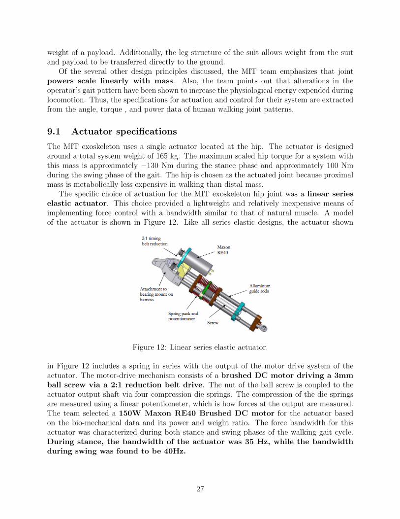
The specific choice of actuation for the MIT exoskeleton hip joint was a linear serieselastic actuator. This choice provided a lightweight and relatively inexpensive means ofimplementing force control with a bandwidth similar to that of natural muscle. A modelof the actuator is shown in Figure 12. Like all series elastic designs, the actuator shown
Figure 12: Linear series elastic actuator.
in Figure 12 includes a spring in series with the output of the motor drive system of theactuator. The motor-drive mechanism consists of a brushed DC motor driving a 3mmball screw via a 2:1 reduction belt drive. The nut of the ball screw is coupled to theactuator output shaft via four compression die springs. The compression of the die springsare measured using a linear potentiometer, which is how forces at the output are measured.The team selected a 150W Maxon RE40 Brushed DC motor for the actuator basedon the bio-mechanical data and its power and weight ratio. The force bandwidth for thisactuator was characterized during both stance and swing phases of the walking gait cycle.During stance, the bandwidth of the actuator was 35 Hz, while the bandwidthduring swing was found to be 40Hz.
27
9.2 Exoskeleton Specifications
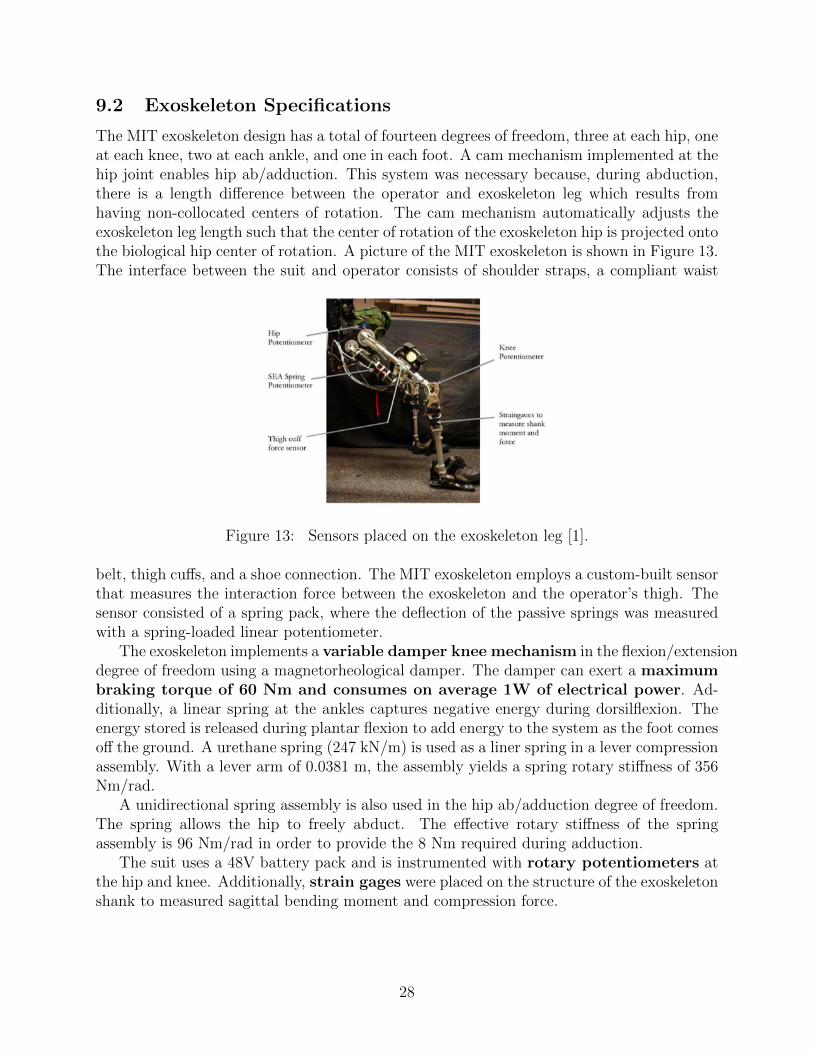
The MIT exoskeleton design has a total of fourteen degrees of freedom, three at each hip, oneat each knee, two at each ankle, and one in each foot. A cam mechanism implemented at thehip joint enables hip ab/adduction. This system was necessary because, during abduction,there is a length difference between the operator and exoskeleton leg which results fromhaving non-collocated centers of rotation. The cam mechanism automatically adjusts theexoskeleton leg length such that the center of rotation of the exoskeleton hip is projected ontothe biological hip center of rotation. A picture of the MIT exoskeleton is shown in Figure 13.The interface between the suit and operator consists of shoulder straps, a compliant waist
Figure 13: Sensors placed on the exoskeleton leg [1].
belt, thigh cuffs, and a shoe connection. The MIT exoskeleton employs a custom-built sensorthat measures the interaction force between the exoskeleton and the operator’s thigh. Thesensor consisted of a spring pack, where the deflection of the passive springs was measuredwith a spring-loaded linear potentiometer.
The exoskeleton implements a variable damper knee mechanism in the flexion/extensiondegree of freedom using a magnetorheological damper. The damper can exert a maximumbraking torque of 60 Nm and consumes on average 1W of electrical power. Ad-ditionally, a linear spring at the ankles captures negative energy during dorsilflexion. Theenergy stored is released during plantar flexion to add energy to the system as the foot comesoff the ground. A urethane spring (247 kN/m) is used as a liner spring in a lever compressionassembly. With a lever arm of 0.0381 m, the assembly yields a spring rotary stiffness of 356Nm/rad.
A unidirectional spring assembly is also used in the hip ab/adduction degree of freedom.The spring allows the hip to freely abduct. The effective rotary stiffness of the springassembly is 96 Nm/rad in order to provide the 8 Nm required during adduction.
The suit uses a 48V battery pack and is instrumented with rotary potentiometers atthe hip and knee. Additionally, strain gages were placed on the structure of the exoskeletonshank to measured sagittal bending moment and compression force.
28
9.3 Control Specifications
The MIT exoskeleton controllers use the fact that desired actuation and active damping atthe knee are functions of gait cycle. Hence, the values of these desired functions can bedetermined from human walking data. Fundamentally, the control strategy works as a statemachine that uses joint angle and measured forces to implement state transitions.
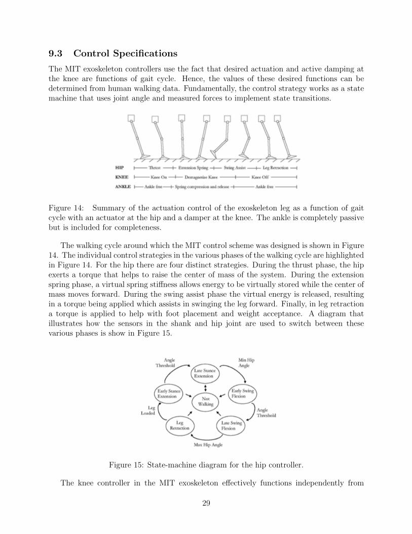
Figure 14: Summary of the actuation control of the exoskeleton leg as a function of gaitcycle with an actuator at the hip and a damper at the knee. The ankle is completely passivebut is included for completeness.
The walking cycle around which the MIT control scheme was designed is shown in Figure14. The individual control strategies in the various phases of the walking cycle are highlightedin Figure 14. For the hip there are four distinct strategies. During the thrust phase, the hipexerts a torque that helps to raise the center of mass of the system. During the extensionspring phase, a virtual spring stiffness allows energy to be virtually stored while the center ofmass moves forward. During the swing assist phase the virtual energy is released, resultingin a torque being applied which assists in swinging the leg forward. Finally, in leg retractiona torque is applied to help with foot placement and weight acceptance. A diagram thatillustrates how the sensors in the shank and hip joint are used to switch between thesevarious phases is show in Figure 15.
Figure 15: State-machine diagram for the hip controller.
The knee controller in the MIT exoskeleton effectively functions independently from
29
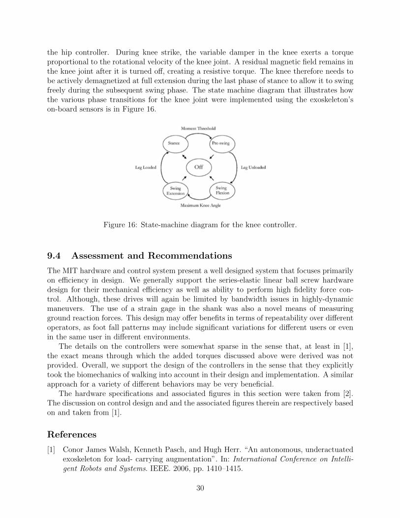
the hip controller. During knee strike, the variable damper in the knee exerts a torqueproportional to the rotational velocity of the knee joint. A residual magnetic field remains inthe knee joint after it is turned off, creating a resistive torque. The knee therefore needs tobe actively demagnetized at full extension during the last phase of stance to allow it to swingfreely during the subsequent swing phase. The state machine diagram that illustrates howthe various phase transitions for the knee joint were implemented using the exoskeleton’son-board sensors is in Figure 16.
Figure 16: State-machine diagram for the knee controller.
9.4 Assessment and Recommendations
The MIT hardware and control system present a well designed system that focuses primarilyon efficiency in design. We generally support the series-elastic linear ball screw hardwaredesign for their mechanical efficiency as well as ability to perform high fidelity force con-trol. Although, these drives will again be limited by bandwidth issues in highly-dynamicmaneuvers. The use of a strain gage in the shank was also a novel means of measuringground reaction forces. This design may offer benefits in terms of repeatability over differentoperators, as foot fall patterns may include significant variations for different users or evenin the same user in different environments.
The details on the controllers were somewhat sparse in the sense that, at least in [1],the exact means through which the added torques discussed above were derived was notprovided. Overall, we support the design of the controllers in the sense that they explicitlytook the biomechanics of walking into account in their design and implementation. A similarapproach for a variety of different behaviors may be very beneficial.
The hardware specifications and associated figures in this section were taken from [2].The discussion on control design and and the associated figures therein are respectively basedon and taken from [1].
References
[1] Conor James Walsh, Kenneth Pasch, and Hugh Herr. “An autonomous, underactuatedexoskeleton for load- carrying augmentation”. In: International Conference on Intelli-gent Robots and Systems. IEEE. 2006, pp. 1410–1415.
30
[2] Conor James Walsh et al. “Development of a lightweight, underactuated exoskeletonfor load-carrying augmentation”. In: Proceedings of the 2006 IEEE International Con-ference on Robotics and Automation. IEEE, 2006, pp. 3485–3491.
10 RoboKnee
The RoboKnee is a prototype system designed to enhance human strength, endurance andspeed. To achieve these goals, RoboKnee uses a low-impedance mechanical system that in-corporates a natural user interface, long life, and is comfortable to wear. The suit’s controllerimplements a “get out of the way” control scheme, where the system interacts with the userthrough a low-impedance interface. This section focuses on RoboKnee’s linear series elasticactuator design and the novel control method the device employs to coordinate its singlepowered knee joint.
10.1 Actuator specifications
The RoboKnee actuator is specifically designed to provide low impedance and high forcefeedback fidelity. The device uses a series elastic actuator to obtain robust output forcemeasurements. The series elastic actuation scheme allows RoboKnee to avoid load cells,which are both delicate and expensive.
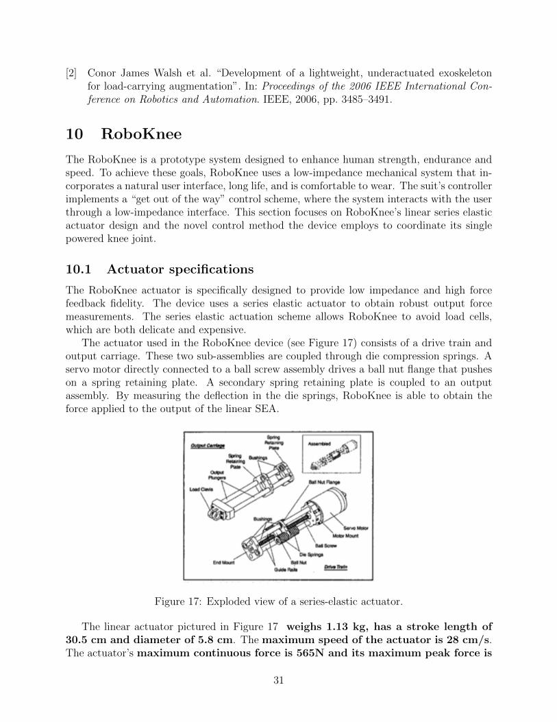
The actuator used in the RoboKnee device (see Figure 17) consists of a drive train andoutput carriage. These two sub-assemblies are coupled through die compression springs. Aservo motor directly connected to a ball screw assembly drives a ball nut flange that pusheson a spring retaining plate. A secondary spring retaining plate is coupled to an outputassembly. By measuring the deflection in the die springs, RoboKnee is able to obtain theforce applied to the output of the linear SEA.
Figure 17: Exploded view of a series-elastic actuator.
The linear actuator pictured in Figure 17 weighs 1.13 kg, has a stroke length of30.5 cm and diameter of 5.8 cm. The maximum speed of the actuator is 28 cm/s.The actuator’s maximum continuous force is 565N and its maximum peak force is
31

1,330 N, with a maximum continuous power of output of 164 W, and maximumpeak power of 634 W.
The force control bandwidth of the RoboKnee actuator is dependent on the magnitudeof the force. Larger forces can induce significant time delays due to the time it takes for thespring to compress. Thus, the small force control bandwidth of the system is 35 Hzand the high force bandwidth is around 7.5 Hz.
10.2 Exoskeleton Specifications
The RoboKnee mechanism consists of a single actuated degree of freedom powering theflexion/extension of the operator’s knee joint. Note that the mechanism itself does notprovide a pathway for transferring weight from a load directly to the ground. The mechanismtransfers loads directly to the users musculoskeletal structure, and focuses primarily onaugmenting user knee joint torques.
The RoboKnee device is composed of an off-the-shelf knee brace modified with structuralpieces to extend the brace and provide actuator attachment points (see Figure 18). The exact
Figure 18: RoboKnee design.
length between actuator attachment points is not listed in the literature, but it appears thatthe attachment points are at minimum the stroke displacement (30.5cm) of the actuatoraway from each other.
RoboKnee uses a linear potentiometer spanning the spring retaining plates to measuredisplacement in the springs and subsequently to measure force at the actuator output. Theforces between the users foot and the ground are also measured using single axis loadcells. Potentiometers which measure the knee joint angle are also employed in this design.
The single actuator as well as control and sensor electronics are run using 4 kg ofnickel-metal-hydride batteries, which give the system only about 30-60 minutesof heavy use.
32
10.3 Control Specifications
RoboKnee employs a hierarchical control strategy, which uses a straightforward mid-levelforce generation scheme coupled with a low-level closed-loop force-based control loop. Thelow-level (joint level) control is a PD control loop.
The RoboKnee’s mid-level controller uses several simplifying assumptions to perform“force amplification” to offload a percentage of the torque required by the user to actuatethe system’s knee joint. This is achieved through positive force feedback amplification. Theapproach uses the measured ground reaction force to calculate the torque that would berequired to produce this force in a static situation,
τ = R × F.
The R term represents the vector from the ground reaction force to the user’s knee andF is the ground reaction force. Note that in RoboKnee’s implementation, F can only beestimated due to the fact that the ankle joint angle and the ground reaction force is assumedto be purely vertical (a limitation induced by the single axis force sensors on the user’s feet).
Once the estimated joint torque, τ , is calculated, an amplification factor specifies howmuch of the required knee torque will be provided by the control system. For example, withunity amplification factor, the actuator would completely compensate for the sensed groundreaction forces. Similarly, with zero amplification, the exoskeleton provides no force.
10.4 Assessment and Recommendations
The RoboKnee is single-joint system that highlights several hardware and control designconcepts that we generally support. We again support the use of a linear ball screw with aseries elastic element to enable high mechanical efficiency and high-fidelity force control inlow to medium speed maneuvers. The concept of using measured ground reaction forces todirectly produce desired knee joint torque is interesting in the sense that it is simple andrelies on minimal information.
The largest potential issues with the RoboKnee are that the forces of the mechanismand any load carried by the operator are fully transferred through the users musculoskeletalstructure. Additionally, the large moment arm of the actuator significantly increases theeffective volume of the operator-system leg, and as such may reduce overall mobility indensely-packed areas.
The discussion as well as figures in this section are respectively based on and taken from[1].
References
[1] Jerry E. Pratt et al. “The RoboKnee: An Exoskeleton for Enhancing Strength andEndurance During Walking”. In: International Conference on Robotics and Automation.IEEE, 2004, pp. 2430–2435.
33
11 Conclusions and Recommendations
The (strength augmentation) exoskeletons we reviewed can be categorized into two generalcontrol categories. The exoskeleton either directly measures user intent (e.g., from EMG dataor direct human-exoskeleton interaction forces), or it estimates intent from measurements atthe exoskeleton joints and applies a sensitivity amplification strategy to shadow the wearer.
Directly measuring user intent is difficult to implement using standard sensing modalities.For instance, EMG data is notoriously noisy and presents both modeling and calibrationchallenges. It would also be extremely difficult to keep these sensors in place to obtainaccurate readings in dynamic environments or activities. For similar reasons, many systemsavoid the use of load cells or complicated sensor networks to accurately obtain operator-robotinteraction forces/torques.
Sensitivity amplification strategies circumvent many of the direct operator-robot sensingissues by estimating human intent from measurements of the exoskeleton hardware. Theissue with this policy is that it cannot generally distinguish between user generated torquesand those produced by external sources. As such, they end up amplifying not only the user’sintent, but also external disturbances, requiring the operator to expend valuable energy tostabilize the system. In dynamic situations the operator may not be capable of activelystabilizing the exoskeleton.
Based on these observations, we recommend (at least in the short term) fusing the twopredominant approaches to exoskeleton control. That is, combining sensitivity amplificationstrategies with direct user measurement to robustly distinguish user intent from external dis-turbances. For instance, it may be possible to use low information density EMG (thresholdedon/off muscle activation signals) with robot force/torque and angular measurements to filterdisturbances from operator-robot interaction forces. As a longer term solution, we highlightresearch in the area of MEMs, nano-fabrication, soft sensors, etc., which has lead to the de-velopment of new, flexible “robotic skin” sensing arrays. Integrating these sensing arrays intooperator clothing (or attaching directly to the exoskeleton), it may be possible to directlymeasure human interaction forces (i.e., estimating pressure / force and exoskeleton contactlocations), which was not feasible in the recent past. Dense sensing arrays add redundancyand can improve measurement reliability and, thereby, feedback control performance.
We also highly stress the importance of high-bandwidth control loops. It is importantthat an exoskeleton’s control bandwidth stays well above (typically 2 − 3×) the humancontrol bandwidth (2 − 5 Hz), to track dynamic motion. Several of the reviewed exoskele-tons controllers are close to lower limit of this human bandwidth threshold under no-loadconditions, and so can interfere in dynamic tasks. Note that these bandwidth issues areprimarily a function of the exoskeleton hardware, and thus special care/analysis needs to begiven/conducted to make sure that the hardware is capable of physically producing requiredbehaviors.
Lastly, the importance of producing hardware that is physically capable of achievingdynamic performance is fundamentally linked to how mass is distributed throughout thesystem. In general, it is desirable to minimize mass, particularly in distal regions. Thedesign objective is often achieved by focusing actuation and leaving certain degrees of free-dom passive (leading to an underactuated system). Underactuated control is a complicatedproblem that is often ignored in the sense that controllers assume the operator will provide
34
necessary forces and torques for the un-actuated degrees of freedom. Though it is possible todeal with the underactuated control problem directly (e.g., optimization-based controllers),there is a balance between feedback and feedforward control. By developing better sensorsand feedback controllers that directly measure and shadow operator intent, exoskeleton con-trollers will become more robust and less sensitive to errors due to underactuated systemassumptions and dynamic model inaccuracies.
35

12 Appendix: Other exoskeleton systems
The web links (URLs) below can be clicked on to view, if your PDF viewer/browser supportsthat. On our browsers you actually have to click on the black part of a letter, not just inthe blue box (if present).
12.1 Overviews
http://powerexoskeletons.com/
http://exoskeletonreport.com/
http://robohub.org/tag/exoskeleton/
http://robohub.org/exoskeletons-new-and-older/
http://neurogadget.com/tag/exoskeleton
http://www.engadget.com/tag/exoskeleton/
http://spectrum.ieee.org/robotics/medical-robots/exoskeletons-around-the-world
http://spectrum.ieee.org/biomedical/bionics/the-rise-of-the-body-bots
http://www.extremetech.com/electronics/139633-will-we-ever-have-iron-man-exoskeletons
https://prezi.com/jygcvfxiesnm/a-brief-introduction-to-biomechanical-exoskeletons/
http://news.discovery.com/tech/robotics/exoskeleton-robots-top-5.htm
http://blog.equipoisinc.com/new-technologies-emerging-aerospace-defense-manufacturing/
http://nextbigfuture.com/2015/03/lower-body-exoskeleton-audi-chairless.html
http://www.army-technology.com/features/featuremilitary-exoskeletons-uncovered-
ironman-suits-a-concrete-possibility
We do not have sufficient information to survey the following exoskeletons.
12.2 Commercial exoskeletons for augmentation
12.2.1 Sarcos XOS/WEAR
We do not have sufficient non-proprietary information to survey this system.http://www.robaid.com/bionics/raytheons-second-generation-exoskeleton-xos-2.
htm
http://techcrunch.com/2010/09/27/sarcos-xos2-the-real-life-iron-man/
12.2.2 Lockheed Martin HULC, FORTIS
We believe this is in collaboration with Ekso Bionics and is similar to BLEEX.http://www.lockheedmartin.com/us/products/exoskeleton/hulc.html
http://www.lockheedmartin.com/us/products/exoskeleton/FORTIS.html
http://www.lockheedmartin.com/us/news/features/2014/mfc-103114-relief-daily-
grind-industrial-exoskeletons-work.html
http://www.dailytech.com/From+HULC+to+FORTIS+the+Evolution+of+Lockheed+Martins+
Incredible+Exosuit/article36421.htm
http://www.wired.com/2014/09/navys-exoskeleton-could-make-workers-20-times-more-
36

productive/
http://robrady.com/design-project/lockheed-martin-fortis-human-powered-exoskeleton
http://www.cnn.com/2013/05/22/tech/innovation/exoskeleton-robot-suit/
12.2.3 Revision Military
PROWLER Human Augmentation System (HAS) Exoskeleton.https://www.youtube.com/watch?v=RKcqHaPhkkM
https://www.youtube.com/watch?v=Zq4amM9u-6o
12.2.4 Activelink/Panasonic
A variety of exoskeleton products.http://activelink.co.jp/en
Assist Suit AWN-03:consists of a 13-pound backpack outfitted with leg supports which allows its wearer to lift upto 33 pounds without any noticeable effort.http://www.engadget.com/2015/08/20/japans-top-oil-company-is-building-an-aliens-
power-loader/
Power Loader Suit:http://pinktentacle.com/2009/09/power-loader-exoskeleton-suit/
http://www.extremetech.com/extreme/173463-worlds-first-affordable-powered-exoskeleton-
is-almost-here-prepare-for-mech-wars
http://www.dealstreetasia.com/stories/panasonic-to-release-commercial-exoskeleton-
to-market-in-4q-2015-9269/
12.2.5 DAEWOO
https://www.newscientist.com/article/mg22329803.900-robotic-suit-gives-shipyard-
workers-super-strength#.U9_FTPldWSp
http://www.geek.com/science/daewoo-dock-workers-now-using-strength-enhancing-
exo-skeletons-1601290/
12.2.6 Innophys: Muscle Suit
Appears to be a power assist suit for lifting. Sip and puff interface? Tokyo University ofScience Prof. Hiroshi Kobayash.https://innophys.jp/
video: https://www.youtube.com/watch?v=Sqr1l909WPwvideo: https://www.youtube.com/watch?v=mNdJgh0ZcrMvideo: https://www.youtube.com/watch?v=NtX81pf-3G4
37

http://blogs.wsj.com/japanrealtime/2014/11/12/wearable-power-assist-device-goes-
on-sale-in-japan/
12.2.7 Noonee (Swiss)
Chair exoskeleton. Passive?http://www.extremetech.com/extreme/188417-rejoice-commuters-and-workers-the-
chairless-chair-exoskeleton-lets-you-sit-down-anywhere-anytime
12.2.8 Sagawa Electronics (Swiss)
Increases reach. Master exoskeleton inside larger slave exoskeleton. Running demonstrated.https://www.youtube.com/watch?v=tYgHdxmCcAI
http://www.ohgizmo.com/2013/07/11/mk3-exoskeleton-suit-promises-to-make-schoolgirls-
better-taller-stronger/
http://www.bitrebels.com/technology/powered-jacket-exoskeleton-japan/
12.2.9 RB-3D
Herculehttp://www.rb3d.com/produits/exosquelettes/
12.3 Academic exoskeletons for augmentation
12.3.1 Kanagawa Institute of Technology
Pneumatic exoskeleton developed at the Kanagawa Institute of Technology, in Atsugi, Japan,allows Akiko Michihisa, a fitness trainer, ...http://www.ubergizmo.com/2007/10/air-pressure-exoskeleton/
12.3.2 Monash University/Chen
http://www.dailymail.co.uk/sciencetech/article-2639939/Super-fireman-The-hi-
tech-exoskeleton-firefighters-superhuman-abilities.html
http://news.discovery.com/tech/robotics/firefighter-exoskeleton-to-the-rescue-
140521.htm
38

12.4 Commercial exoskeletons for assistance and rehabilitation
12.4.1 ReWalk
On the sixth generation of this device.http://rewalk.com/
12.4.2 Cyberdyne
up to HAL 5 (already covered)http://spectrum.ieee.org/robotics/medical-robots/exoskeletons-are-on-the-march
http://www.computerweekly.com/photostory/2240108388/Photos-Cyberdyne-Hal-robotic-
exoskeleton-to-help-paralyzed/7/Japan-beats-the-US-to-it-Cyberdyne-Hal-robotic-
exoskeleton-to-help-paralyzed
http://www.dailymail.co.uk/sciencetech/article-2384930/Robotic-exoskeleton-help-
rehabilitate-disabled-people-passes-safety-tests--paving-way-sale-UK.html
12.4.3 Rexbionics
REX exoskeletonhttp://www.rexbionics.com/
http://www.gizmag.com/rex-robotic-exoskeleton/15736/pictures
http://www.stripes.com/news/exoskeleton-could-benefit-troops-with-spinal-cord-
injuries-1.113657
http://www.funis2cool.com/cool/rex-the-robotic-exoskeleton-could-change-the-
lives-of-disabled-people.html
12.4.4 Indego/Parker Hannafin
Commercialization of Vanderbilt exoskeletonhttp://www.indego.com/indego/en/home
https://www.youtube.com/watch?v=-bYYmZNxaZk
http://www.roboticstrends.com/article/parker_hannifin_indego_exoskeleton
http://www.crainscleveland.com/article/20141112/BLOGS03/141119915/parker-hannifin-
accepts-the-challenge-of-commercializing-the-indego--41951672-812546791-1442419256=:
6352--
12.4.5 Honda
2 devices in the Walking Assist Program: Bodyweight Support Assist and Stride Manage-ment Assist (SMA):http://corporate.honda.com/innovation/walk-assist/
http://world.honda.com/Walking-Assist/
39
http://www.slashgear.com/honda-demo-walking-assist-exoskeleton-for-elderly-disabled-
2211295/
http://singularityhub.com/2010/09/13/hondas-exoskeletons-help-you-walk-like-
asimo-video/
12.4.6 Hyundai
Appears to be similar to BLEEX.Article and video: https://forums.xilinx.com/t5/Xcell-Daily-Blog/Hyundai-s-wearable-exoskeleton-restores-personal-mobility-to-the/ba-p/647031
Hyundai’s exo project is lead by Dongjin Hyun who did his PhD with Homayoon Kazerooniat UC Berkeley and a PostDoc with Sangbae Kim at MIT.
12.4.7 3D Systems
3D printed exoskeleton. Using Ekso Bionics technology.http://www.dezeen.com/2014/03/05/3d-printed-exoskeleton-helps-paralysed-users-
walk/
12.4.8 ExoAtlet (Russian)
Appears to be similar to BLEEX.http://robohub.org/clinical-trials-begin-for-russias-first-medical-exoskeleton/
12.5 Academic exoskeletons for assistance and rehabilitation
12.5.1 Vanderbilt
Commercialized by Indego/Parker Hannafinhttps://en.wikipedia.org/wiki/Vanderbilt_exoskeleton
http://research.vuse.vanderbilt.edu/cim/research_orthosis.html
http://www.dailytech.com/Iron+Man+New+Robotic+Exoskeleton+Helps+Paraplegics+Walk/
article29079.htm
12.5.2 Mindwalker
Key feature is actuation in lateral plane. Each of the powered joints has a series elasticactuator, which can deliver 100 Nm torque and 1 kW power.https://mindwalker-project.eu/
http://www.3me.tudelft.nl/en/about-the-faculty/departments/biomechanical-engineering/
research/dbl-delft-biorobotics-lab/exoskeleton/
http://www.utwente.nl/ctw/bw/research/projects/MINDWALKER/
40
http://tnsre.embs.org/2015/03/27/design-control-mindwalker-exoskeleton/
12.5.3 U. Penn
Student project that got some press.http://www.popsci.com/article/technology/invention-awards-2014-powerful-portable-
and-affordable-robotic-exoskeleton
12.5.4 East China University of Science and Technology
Fully portable hydraulic exoskeleton. Unclear if this is for assistance or augmentation.Video: http://v.youku.com/v_show/id_XMTg3MTQzNjgw.htmlHeng Cao: “most difficult thing was control bandwidth”, so they are probably not usinghigh quality valves.http://mech.ecust.edu.cn/s/131/t/147/6a/07/info27143.htm
12.5.5 University of Electronic Science and Technology of China
Prof Hong Cheng did his Postdoc in CMU from 2006-2009 in CS. He is very famous in Chinafor his exoskeleton work.Chinese Video: http://society.kankanews.com/s/2014-12-17/0016103932.shtmlhttp://uestcrobot.net/~hcheng/
http://www.uestcrobot.net/?q=node/291
12.6 Government Programs
12.6.1 TALOS
We assume the reader is familiar with this program.
12.6.2 DARPA Warrior Web
We assume the reader is familiar with this program.
12.6.3 Japan: NEDO
There was a Japanese government (NEDO) oriented project, “Robotic Devices for NursingCare Project”, that intended to boost the practical nursing care robots development, includ-ing exoskeleton.http://robotcare.jp/?lang=en
http://robotcare.jp/?page_id=29&lang=en
They made a center to test the safety for robots including exoskeletons.http://www.rtnet-biz.jp/rtsic/
41

12.6.4 EU: BALANCE program
http://balance-fp7.eu/
http://cordis.europa.eu/project/rcn/106854_en.html
42


![Shaping neuroplasticity by using powered exoskeletons in ... · for the patient of a real-world setting ambulation [10, 11]. To this end, wearable powered exoskeletons, e.g., the](https://static.fdocuments.net/doc/165x107/5f0c28a57e708231d434072f/shaping-neuroplasticity-by-using-powered-exoskeletons-in-for-the-patient-of.jpg)


![Passive exoskeletons for assisting limb movement · · 2006-11-30Passive exoskeletons for assisting limb movement Tariq Rahman, ... an upper-limb motion assist system [9], ... RAHMAN](https://static.fdocuments.net/doc/165x107/5b03d0f67f8b9a3c378cc48e/passive-exoskeletons-for-assisting-limb-movement-exoskeletons-for-assisting-limb.jpg)