A SURVEY OF ALUMINUM TO STAINLESS STEEL TRANSITION...
28
SLAC -TN-67-5 U, Cummings This is an internal informal note further disclosed without approval A SURVEY OF ALUMINUM TO STAINLESS STEEL TRANSITION TECHNIQUES Urban K. Cummings Stanford Linear Accelerator Center Stanford University, Stanford, California ABSTRACT A comprehensive survey is made of current methods for join- ing aluminum alloys to austenitic stainless steels, With several exceptions the scope is limited to those techniques which are poten- tially suitable for all-metal ultra-high vacuum applications. Com- mercially available transitions are described as well as some techniques which have been successful in various space and military applications but are not on the market. Evaluation of the methods described is limited to several techniques which appear suitable for application to the colliding beam storage ring proposed by the Stanford Linear Accelerator Center.
Transcript of A SURVEY OF ALUMINUM TO STAINLESS STEEL TRANSITION...

SLAC -TN-67-5
U, Cummings
This is an internal informal note
further disclosed without approval
A SURVEY OF ALUMINUM TO STAINLESS STEEL TRANSITION TECHNIQUES
Urban K. Cummings Stanford Linear Accelerator Center
Stanford University, Stanford, California
ABSTRACT A comprehensive survey is made of current methods for join-
ing aluminum alloys to austenitic stainless steels, With several
exceptions the scope is limited to those techniques which are poten-
tially suitable for all-metal ultra-high vacuum applications. Com-
mercially available transitions are described as well as some
techniques which have been successful in various space and military
applications but are not on the market. Evaluation of the methods
described is limited to several techniques which appear suitable
for application to the colliding beam storage ring proposed by the
Stanford Linear Accelerator Center.

I. INTRODUCTION
The vacuum chamber for the proposed electron positron colliding beam storage
ring at SLAC’ will be constructed of extruded 6061-T6 aluminum alloy. The design
parameters which dictate the chamber configuration suggest the use of an extruded
section. The choice of aluminum was dictated by its dependable extrudability,
low electron desorption coefficient2 high synchrotron radiation absorption and
high thermal conductivity. The latter property permits the water- cooled radiation
absorber to become an integral part of the extrusion rather than a separate body
inserted into the chamber 0 The shape of the chamber passing through the bending
magnets is rectangular; that passing through the remaining portion is circular.
The rf cavitiesare fabricated of aluminum.
II. REQUIREMENTS
Development of reliable ultra-high vacuum transition sections for use
between the aluminum chamber and such stainless steel appurtenances as ion
pumps, view ports, bellows, expansion joints, high voltage insulators, etc. ,
is of prime importance.
III. SCOPE
Only those transition techniques which possess long term dependability for
ultra-high vacuum applications would be acceptable. Specifically they must main-
tain vacuum integrity (leak rate < 2 X 10-l’ std cc% per set He) while
withstanding repeated bakeout cycles at temperatures above 200°C in the presence
of a moderate field of ionization radiation. Hydrocarbon contamination causes
significant increases in the electron desorption coefficients. Therefore the obvious
-2-

elastomer gasketed joint between aluminum and stainless steel flanges is not
suitable. Although Viton* compounds have been known to withstand 200°C bake-
out3 and display some radiation resistance, 4 the presence of hydrocarbon con-
tamination associated with such polymers cannot be tolerated in the vacuum
chamber. 5
The possibility of using a Polyimide** material as reported by Hait is under
consideration. Although Polyimide appears capable of 300’ C bakeout and probably
possesses the greatest radiation resistance of any available synthetic, its uncer-
tain desorption characteristics require a careful systematic evaluation.
This note reports on the search for an all-metal transition. Some of the
methods given are all-metal junctions possessing suitable leakage reliability but
not capable of withstanding the required bakeout temperature. They are not under
consideration and are reported here for information purposes only. Many of
the processes described have been used to join a wide variety of metal combina-
tions. It is the purpose of this technical note to disclose these processes as they
apply particularly to aluminum-to-stainless steel junctions. Their application to
other metal transitions has been omitted in most cases.
IV. CATEGORIES
Transition sections can be classified by either the scheme used to join them,
such as bonding or brazing, or by their functions, such as separable or insepa-
rable. Both must be considered for use on the storage ring because certain items
as ion pumps and view ports must be detached periodically. If the aluminum-to-
stainless steel interface can be provided at the flanged junction, cost can be reduced
* T.M. Reg. I.E. DuPont
** T.M. Reg. I.E. DuPont
-3 -

from that which would require flanges plus a transition piece. For this reason the
various methods will be grouped as separable or inseparable. Further groupings will
be made in two cases where the techniques are basically identical.
V. INSEPARABLE JUNCTIONS
A. Clad Metals
Recent advances in metal-to-metal layering6 and cladding7 techniques have
made it possible to assemble an integral structure of fundamentally different
metals heretofore not joinable o
The automotive, construction, and consumer goods industries have created
a demand for veneered metals. For reasons of environmental protection, cost
economy, weight savings or ornamental use, most of the widely used ferrous and
nonferrous metals have now been joined to one another by cladding. The major-
ity of these composites are made in either sheet or strip form. The cladding
can be accomplished by mechanical bonding, electrochemical or electroless
chemical deposition, or by vapor or vacuum deposition techniques. By
shaping these materials into the required configuration and selectively removing
the clad metal from the base metal (either before or after shaping) one can form
a transition of intimate bond between metals which are difficult to join by conven-
tional welding or brazing techniques.
1. Roll Bonding
The major quantity of mechanically joined cladsheet stock is produced by roll
bonding. An adherent bond is formed between the metal layers by the high pressure
(25 to 50 KPSI) and moderate temperatures (700’ to 900’ F) which accompany the
rolling process. A 10% reduction in thickness is normal. Carefully controlled
preparation of the mating surfaces by chemical treatment is an obvious necessity.
-4-

The exact procedures involved are proprietary except that some fabricators ad-
mit to using 1100 or 1145 alloy cladding on the side of the aluminum sheet which
faces the stainless steel. The preferred base aluminum alloy is 3003 or 3004.
Type 304 stainless steel is used because of its low cost and availability., Other
austenitic alloys could be used with equal success0
Three manufacturers of roll-bonded stock were located. There may be others.
A pioneer of these clad materials is Metals and Controls, Inc. , (a) an old-timer in
making bi-metallic strips for thermostats. They will bond any 200, 300 or 400
series stainless steel to 3003 or 1100 alloy aluminum of a thickness ratio up to
50/50 for a total thickness of 0.040 inch to 0.130 inch in strips up to 16 inches in
width. The stainless steel is in annealed condition, the aluminum is l/2 hard, or
can be supplied annealed. They stated they can bond also to 2024 aluminum alloy
but not to 6061.
The group at SLAC planning the storage ring facility acquired some of this
material for evaluation. The 304 stainless steel is 0.025 inch thick; the 3004 alu-
minum 0.060 inch. It was hydroformed into 3-inch diameter cups about 2-l/4
inches deep. The bottom of the cup was removed and the aluminum etched off of
the stainless steel l/2 inch from one end. On the other end, l/2 inch of the stain-
less steel was machined off of the aluminum. These steps are illustrated in Fig. 1.
The result is a tubular transition to which each metal tube can then be welded. Over
a dozen of these were made and tested, The 3004 alloy was welded to a 6061 aluminum
pumpout tubulation using 4043 filler rod. The stainless steel end was sealed off with
a cap plate by tungsten inert gas (TIC) fusion weld. Three of these cups were baked
out at temperatures from 200’ to 300’ C for up to 72 hours with no detectable leak
greater than the 2 X 10-l’ std cc’s/sec Helium sensitivity of the leak detector. The
width of the overlapping band of aluminum-to-stainless steel ranged from l/2 inch
(a) Letter references: See Appendix “Manufacturers’ Names and Addresses. ”
-5-

Fig, 1. Transition formed from stainless steel clad aluminum sheet.

to l-1/2 inches on various samples. Metallographic examination of the aluminum-
to-stainless steel interface revealed no evidence of intermetallic diffusion. The
materials apparently are bonded by the adherent forces of intimate contact without
intermediate chemical reaction. The manufacturer states that no interstitial mate-
rial was used between the two metals. From the results of our tests it would ap-
pear that this scheme would be satisfactory for use on the proposed storage ring.
The principal limitation of this method is that of maximum diameter and depth of
cup that can be formed from available widths. Except for samples, orders of
this material require a mill run of 1000 lbs. minimum,
Aluminum Company of America (ALCOA)(b) is another supplier of roll-bonded
aluminum-to-stainless steel. It is marketed as “Duranel”8 by their Wearever
Division and was developed for use in pots, pans and other cooking utensils. For
this use, the stainless steel is 0,009 to 0.010 inch thick on 0.060-inch to 0, lOO-
inch aluminum. This can be obtained without a mill quantity run and is available
in widths greater than 15 inches. The thin gauge of the stainless steel does limit
the freedom of joint design for TIG welding.
The third source for roll-bonded stock is Composite Metals, Inc, (‘) They
imposed no restrictions on the quantity of the initial order or the range of thick-
nesses to be joined. Four pieces 18 inches square were obtained. The price is
about $2.50 per pound, composed of 0.105 inch thick 3004 aluminum (preclad
with a thin veneer of 1145 alloy) and 0.045 inch thick 304 stainless steel. They
claim peel strengths of the junction greater than the yield strength of the aluminum.
These samples have not yet been tested.
2. Static Bonding
Another mechanical bonding method is described in a 1959 patent9 assigned
to ALCOA. In this process the bond between metals is made by what the inventor
calls “static hot pressing. l1 The aluminum is forced to adhere to the stainless
-6 -

steel by means of applying a temperature and pressure which exceeds the yield
point of the aluminum, thereby causing a swaging action. It was developed for
the purpose of applying stainless steel cladding to the sole plates of hand irons,
the advantage being the sole plate was aluminum cast with the heating element
imbedded in it. This forging process might be applied to fabricating transitions
by the use of wrought aluminum. It would permit a wider variety of shapes to be
formed than those which are limited by techniques of shaping sheet material,
B. Warm Welding
The work described by Batzer and Bunshah 10 which they have named “Warm
Welding” is worthy of mention. Although they did not test aluminum-stainless
steel combinations, such a junction may be possible,,
Their combined process of 2-step surface cleaning conducted in ultra-high
vacuum, plus the prolonged applied pressure at elevated temperature, makes pos-
sible a structured bond between the two metals being joined. Batzer’s 30 expe ri -
ence with aluminum foil gasketed high-vacuum flanges (see Section VI-A) indicates
warm-welding of aluminum to stainless steel is practical. Stainless steel UHV
flanges joined with an aluminum foil gasket and baked for 30 hours at 400’ C at
high vacuum and with high gasket loading required a wedge to pry them apart.
After separation, much of the aluminum had to be scraped from the flanges.
Batzer suggests that the aluminum oxide is dissolved in the aluminum under this -
environment, thereby permitting a diffusion type bond between the metals.
C . Aluminum Deposition Methods
A third method of cladding metals is by high-rate deposition of aluminum
vapors.
1. Vacuum Evaporation
A pioneer in this field has been Temescal Metallurgical Corporation. (d) Al-
though there is a dearth of detailed information available, in general it is simply
-7-

a scaled-up version of the same electron beam techniques used in thin film vacuum
evaporation. Film thicknesses in the order of inches can be applied to substrates
by the use of electron beam melting 11 and the 50-kW power supplies now available.
Aluminum has been deposited from these sources at rates of 1 to 2 lbs/hr, l2 Food
container and automotive muffler applications are making use of vapor deposited
aluminum on steel, Normally a diffusion barrier of titanium is applied to the steel
before depositing the aluminum. Stainless steel sheet stock clad with evaporated
aluminum would probably not be competitive with mechanically bonded layered
metals. It does offer many possibilities of depositing aluminum onto shapes for
subsequent welding or brazing to aluminum as transitions. For more on vacuum
evaporated coatings, see Section V.K. 4 of this report.
2. Vapor Deposited
Vapor deposited coatings are distinct from vacuum evaporated in that they
are normally performed at atmospheric pressure. The Aluminum Alkyl Vapor
Deposition Process 13 has been a laboratory technique for producing pore-free
high-purity (99.99%) aluminum coatings on any substrate that can be heated to
356’ F. General Technologies Corporation (e) has developed a commercial-scale
capability utilizing this process for batch or continuous coating. Deposition rates
on the order of .5 mil per minute have been achieved on a wide variety of shapes.
In response to a SLAC request, the producer offered to coat sample copper
strips with a 0020-inch thick deposit of aluminum on a best-effort basis at $125/day.
No inquiry was made regarding stainless-to-aluminum transitions.
D. Molten Dip Processes
Several other methods have been used for transitions by precoating the steel
prior to welding to the aluminum. Miller, 14 and Miller and Mason15 describe
hotdipping 304 stainless steel in 1100 aluminum alloy at 1300’ F or rub-coating
-8-

with 718 aluminum alloy. Finke and Begerman 16 hot-dipped steel in pure alumi-
num and in aluminum containing 8.5% silicon. The silicon alloy produced a
thinner iron-aluminide diffusion zone 0
Richard Cole at A. D. Little, m has described a similar dip process 17 which
he and others have used for making transitions up to 4 inches in diameter in cer-
tain cryogenic apparatus 0 One to two mils thickness of aluminum is accumulated
on the stainless steel tube by dipping it in flux sprinkled molten 1100 aluminum.
After cooling, an aluminum tube is forced over part of the aluminum coating and
TIG welded to it using 4043 alloy filler. This junction withstands thermal cycling
from ambient to 20’ K.
E. Diffusion Bonding
A report by Crane et al. , 18 of the Boeing Company describes the development
of a diffusion bonding process joining 2219 or 6061 aluminum to 321 stainless steel.
This document also reports their tests of welding and brazing of several aluminum
and stainless steel alloys. It also contains an excellent bibliography on joining
aluminum to stainless steels. Briefly, the process is as follows:
On 8-inch and 20-inch diameter sample tubes, a diffusion barrier of silver is
electro-deposited onto both the i. d. of the aluminum ring and the o. d. of the stain-
less steel ring in the area of mutual contact. The outer aluminum ring is expanded
by heating and the inner stainless ring shrunk by immersing in liquid nitrogen.
They are inserted and equalized to room temperature. Machined clearances were
chosen to optimize the hoop stress caused by differential thermal expansion. The
assembly is then soaked 2 to 4 hours in an air furace at 400’ F to 600’ F to accel-
erate the diffusion bonding process. In tests, shear strengths of 15 to 20 KS1 are
attained. Specimens are subjected to test at -320’ F and -423’ F but not at elevated
temperature since they were intended for cryogenic application. Parts were reported
tested with helium leak detector but no quantitative results given. These junctions
-9-

were developed for use by NASA but are not being marketed by Boeing. The proc-
ess could be applied to noncircular sections with the use of a platen press,
For the person interested in stainless steel-to-aluminum transitions, this
Boeing report is a most comprehensive document covering many approaches to
transitions D
F. Tandem Extrusion
Nuclear Metals, Inc.,(g) has developed a highly reliable but relatively expen-
sive transition by a novel method called Yandem tubular extrusion. ‘I 19 The proc-
ess involved is approximately as follows: Cylinders of aluminum and stainless
steel, slightly over-size and shorter than the required size of the finished part,
are placed end to end in a mild steel container, welded shut, pumped out and
sealed. This cartridge is then forced through extrusion dies. In so doing, an
intimate tapered junction is formed between the two inner pieces. The outer shell
is next machined off and finally the 0-d. turned and the i.d. bored to the dimensions
desired,
These units are available in 304 stainless steel to 6061 aluminum alloy in
diameters up to 4 inches. The manufacturer states they could be made as large
as 6 to 8 inches in diameter. They claim leak integrity to 1 x lo-’ cc’s/sec and
bond strengths of over 40 KPSI at room temperature. Strips cut from the junction
and tensile-tested always fail in the aluminum, not in the bond. Prices range
from $125 up to $900, depending on size and quantity ordered.
G. Fricton Welded
Paul Gripshover 20 at Battelle Memorial Institute is developing the use of spin-
friction welding for joining dissimilar metals. Most of the work has been done so
far in the zircalloy, hastalloy, inconel/incalloy series. Test joints on aluminum-
to-stainless steel indicate they are not difficult to join by this process, By rotating
one component at low speed and high torque and bringing the other component up to
- 10 -

it with careful control of such parameters as joint temperature, time and torque,
a fine-grained, diffusionless bond with high impact strength can be achieved.
Gripshover is making test junctions in 304 stainless steel to 6061 aluminum lo-inch
pipe for evaluation. Lawrence Radiation Laboratory in Livermore has obtained
one of these machines, It is capable of 10, OOO-pound axial thrust, American
Machine and Foundry Company utilizes this same technique for joining steel gears
for the automotive industry. 21
Gat zek22 has also reported satisfactory results in friction-welding l-inch
o, d. x 0.25-inch wall 6061 aluminum to 304 stainless steel.
Tube Turns, Inc. , w markets an inseparable bolted flange transition from
304 stainless steel to 5083 aluminum which they say is “jointed together by cold
pressure welding to produce a strong, ductile, solid phase bond. It Their tests
include thermal cycling 212’ F to -320’ F, and helium leak tests to 1 X 10 -9 atm
cc’s/sec. They are made in 4-l/2-inch o,d. to 16-inch o.d, sizes. From the
description, one might guess they are friction welded.
H. Electron Beam Welded
Electrofusion Inc. ti ) has joined 1-l/2-inch diameter aluminum and stainless
steel tubes using electron beam welding techniques. A l/16-inch wide silver
intermediary was placed at the junction between the tubes. The bond is made by
fusing the aluminum and stainless steel components to the silver and not to each
othf The work was performed for Applied Radiation Co. 0 The parts were
leak tigr:: mass spectrometer helium leak test. No mechanical tests were
performed. We obtained several samples sectioned from both weld areas of one
of the tubes. Inspection after mounting and polishing revealed a very narrow
- 11 -

fusion area indicating good control of the beam spot size. No signs of porosity
or other inhomogeneity were detected. It was a full penetration weld thoughout
most of the specimens examined.
The mechanical properties of such a junction should be analyzed. The advan-
tages of this method are the lack of surface contamination achievable in the vacuum
environment and the freedom of joint design.
I. Flash -Welded
A trimetallic junction of 304L stainless steel to llOO-H18 aluminum using a
copper interface has been developed by C. E. 23 Burley of Reynolds Metals Co.
for cryogenic applications. Over 100 samples in l-inch pipe size were made by
Thompson Electric Welder Co. (k) using their model F4 (250 KVD) flash welder.
The only surface preparation used was to square the ends of the tubes to be joined.
A fixture is required to bring the parts together axially as the voltage is applied.
A l/2-inch long OFHC copper section is first flash-welded to the stainless steel.
The aluminum-to-copper weld is made last. Tests using Monel or nickel at the
interface were less satisfactory.
Forty-five out of the 62 junctions made with copper were leak-tested with a
helium mass spectrometer. No leaks were detected before or after 10 thermo-
cycles from 150’F to -320’F. Leak detector sensitivity was < 1 x 10 -lo std
cc’s/sec per division. Ultimate tensile tests at room temperature and -320°F
were 10,190 lbs and 9,680 lbs, respectively. The weld flash was removed before
tests began. These units are not available off the shelf but will be made by
Thompson on order. Two inches is the largest size presently made. Four inches
is the maximum that could be made with existing apparatus. Power requirements
and the massive handling fixtures needed are the limiting factor. An estimated
cost of $4 each was given for the l-l/2-inch size but the set-up and die charge
of $400 to $500 make the cost of small quantities prohibitive.
- 12 -
.
J. Explosive Formed
Battelle Memorial Institute@) is also working on various transitions, tubular
and otherwise, formed by explosive charge. These are made by beveling one end
of the aluminum and stainless steel tubes (at 45’ to 60’) and fitting them together.
A restraining plug is inserted into the tube and located at the beveled junction.
A circular explosive charge is placed outside the tubes in the same location. The
implosion restrained by the plug causes the metal to flow and an adherent junction
is formed. This process is still in the developmental stage but junctions of good
reliability have been made up to 6 inches in diameter, using aluminum, 43 46 steel,
stainless steel, inconel and zircalloy. Costs are approximately l/3 those for
tandem extrusions and twice those for spin-friction weldings of comparable size.
This technique may also be applicable to seam welding. A current article on shock
forming24 describes other applications of this technique and indicates the advance-
ment which has taken place in recent years.
K. Brazed Junctions
The preponderance of aluminum-to-stainless steel transitions being used today
are joined by brazing. A number of schemes are being used successfully, the
principal difference being the prebraze surface preparation applied to one or both
metals being joined.
1. Solar Aircraft(m) manufactures and stocks lap joint transitions in sizes
from 3/8-inch to 6-inch diameter pipe and tube sizes. These are dip-brazed in
molten flux using aluminum braze alloys and a proprietary titanium pretreatment 25
on the stainless steel. The manufacturer’s literature states that these units have
withstood twenty temperature excursions from 600’ F to -320’ F with no indication
of leakage. Minimum acceptance standard is 10 -8 cc/set on a mass spectrometer
leak detector. McLaughlin and Tanabe 26 have also tested this unit.
- 13 -

2. Bi-Braze@) also manufacturers dip-brazed transition couplings employ-
ing an “aluminizing process” 27 as a pretreatment to the steel component. They
are available in 6061 to 304 alloys in sizes from l-inch to lo-inch pipe sizes.
Prices range from $47 to $343 depending upon quantity ordered.
Care must be exercised in selecting an aluminum dip-brazed component in
order to avoid those brazing materials which contain zinc and/or phosphorous
compounts. Such contaminants are not likely to be acceptable in an ultra-high
vacuum system subject to bakeout. Thorough cleaning to remove traces of chlo-
ride and fluoride fluxes is also essential.
3 0 Gatzek2’ describes 3-inch-diameter transitions being made at North
American Aviation, using a tin pre-coating on 304-L stainless steel joined to
6061 aluminum by salt-bath brazing. A nickel strike is applied prior to the elec-
trodeposited tin. Helium mass spectrometer leak tests were limited to 1x10 -8
std cc*s/sec He. A North American Aviation proposal 28 reports an 8 -inch-di-
ameter transition having been dip-brazed also using a tin interface.
4, Still another approach to prebraze surface preparation is given by Nord
and Huschke. 29 This process utilizes a 0.00075-inch vacuum evaporated titanium
film on the stainless steel. On top of this is deposited 0.040 inch of 4043 aluminum
alloy by means of high-rate electron beam evaporation. This surface then can be
welded or brazed to. This process was developed in conjunction with Temescal
Metallurgical Corporation 0% and is capable of temperature excursions from 1000° F
to -423’ F. The test data report is thorough and complete. These junctions have
been successfully used on J-2 rocket engine control valves. Each valve has 11 such
joints. The report also describes other attempts using silver interface coatings
which were not successful.
- 14 -

L. Ultrasonic Bonding
Werner Schulz in the SLAC M E & F Group suggests the use of ultrasonic
energy for bonding aluminum to stainless steels. By applying a copper flash
onto stainless steel sheet (and sintering 3 minutes at 900’ C in dry hydrogen),
he has bonded O.OOl-to O.OlO-inch low alloy aluminum wires to stainless steel
with the use of a Mullard ultrasonic pencil transducer. The power input was ap-
proximately 100 watts, the force approximately 20 psi. In bond strength tests,
the wire separated before the bond failed. The possibility of bonding circular
and other shapes by this method should be investigated. The process is inher-
ently contamination free and suitable for ultra-high vacuum use.,
Reference is made to a most comprehensive bibliography on Ultrasonic
3o Welding covering the years 1960 to 1966.
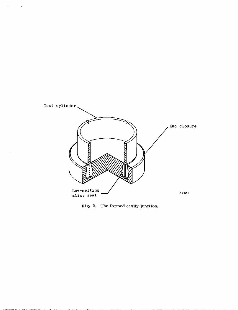
M. The Formed Cavity Technique
Strictly speaking, this should be classed as a semiseparable junction. The
seal is made with a low melting alloy, is easily separated, and capable of unlimited
reconnections. Although the seal is not bakeable, it is all-metal and useful on
certain high-vacuum applications and therefore worthy of mention. The basic
principle is illustrated in Fig. 2. One component to be joined is provided with
an annular re-entrant cavity on the end to be joined. The mating end of the other
component is machined with a tee-shaped flange which fits into the re-entrant
cavity. The walls of the cavity are tapered so that if the components tend to pull
away from each other, they become more tightly wedged in the solidified low melt-
ing alloy which fills the cavity. This principle was developed at NASA-Lewis Re-
search Center31 for use on boltless pressure vessel tests. Since the low melting
alloy expands on cooling, it is self-sealing. Seals of this type have been used on
cryogenic applications up to 2000 psi. Several other possible joint configurations
- 15 -
Test cyli nder
\
Low-melting / alloy seal
Fig. 2. The formed cavity junction,
End closure
791Al

are suggested in the report. Although only aluminum is mentioned as a parent
metal, the same method could be applied to aluminum-stainless steel transitions.
N. Welded Silver Sleeve
Cryogenics Associates (0) manufactures a stainless steel-aluminum transition
for cryogenic use similar to one which Linde Company (P) has used on cryogenic
dewards. It is simply a silver sleeve, of adequate thickness to weld to, which is
snugly fitted over the butted ends of the aluminum and stainless steel tubes to be
joined. The mechanical strength of the junction is developed by the close-fitting
sleeve which overlaps the end of each tube for a length approximately equal to the
diameter. Cryogenics Associates offered to make two of these, 8 inches in di-
ameter x l/4-inch wall in 304 to 6061 alloys for $166 each. No test data was
available on this process except that they have been used in cryogenics service
and are said to be vacuum tight.
0. Alumicoat Process
Some preliminary work on a transition based on hot-dip coating was done
here at SLAC by Dieter Walz and Luther Lucas for use on the slits and collimators
in the Beam Switchyard.
Several 6-inch diameter 304 stainless steel tubes, 3 inches long, were dip-
coated all over with a material called “Alumicoat” by the Arthur Tickle Engin-
(q) eering Company. One end of the tube was TIG welded to a l/8-inch thick 6061
aluminum cover plate. This weld was made with 4043 filler and was leak tight
to lo-lo std cc%/sec. The weld appearance was excellent, The other tubes
were butt-welded to 6061 aluminum tubes of the same diameter with the same
filler rod. Equally good weld appearance and leak tightness were achieved. No
mechanical tests were performed nor further evaluation undertaken due to the
lack of developmental time available. Off -the -shelf transitions were used instead.
- 16 -

The same company produces “bi-metallic castings” in which aluminum is cast
onto or around shapes of higher melting alloys to form a bi-metallic junction.
P. Centrifugal Casting
Gerald Fritzke, M E & F metallurgist, suggests the possibility of dual metal
centrifugal castings W as a stainless-to-aluminum transition. Usually made in
tubular form, centrifugal castings can be made as large as 3 feet in diameter and
up to 10 feet long. They consist of two centrifically-cast concentric layers “bonded
in the casting process D It “They are formed by pouring the first or outer metal
into a horizontal spinning mold, protecting its i-d. against oxidation and scruff
accumulation, waiting until the surface has just solidified and, without interruption
of spinning, pouring the second or inner metal onto the first. I’ The manufacturer
claims a metallurigical bond with some solution (and some microporosity) at the
interface. These castings have been successfully made in combinations of low
alloy carbon steel, 300 and 400 series stainless steels, alloy 250 (27% Cr), and
cast irons. They say they can also be made to copper if it is the inner component.
No mention is made in their literature regarding aluminum.
VI. SEPARABLE JUNCTIONS
A. Aluminum Foil Gasket
The majority of evaluative effort on a separable transition for use on the
Storage Ring has been spent on BatzerOs 32 aluminum-foil-gasketed, ultra-high
vacuum flange system. We have adapted it to transition service by slightly re-
designing the flange to be made of aluminum, By increasing the section modulus
to obtain the same flange rotation for the lower stress values of aluminum (which
are allowable for bakeout temperatures of 200’ C), we were able to duplicate with
dissimilar metals the success he had achieved with stainless steel flanges.
- 17 -

An 8-inch o. d. by 6-inch i,d. test flange set has been baked 5 times to
220’ C to test the minimum tightening torque necessary on the bolts. A 1 x 10 -8
std cc/set leak occurred on the sixth cycle. After that, the bolts were tightened
to the recommended torque. No further leak was found in four additional cycles.
Following this, a room temperature impact test was performed on the same
flange set by dropping a 3-pound weight on the edge of the flanges. Leak detector
sensitivity was always 2 X 10 -10 std cc’s/sec per Div. (He) or better, No leaks
were precipitated by dropping the weight from heights of 1, 2, and 3 feet. At a
height of 4 feet, a leak of approximately 1 X lo-’ cc/set was detected. The fault
caused in the foil gasket apparently heals itself. The helium response leveled
off within 2 minutes and began receding. After 10 minutes, no helium response
was detected. The same result was obtained in dropping the weight from 5 feet
except the size of the leak was one order of magnitude greater and it took 25 min-
utes to heal. A gasket cycling test was performed next on the same flange set.
Ten gasket changes were made with 220’ C bakeout applied at each cycle. One
leak occurred after cooldown on cycle #4, otherwise no leaks detectable greater
than the stated 2 x 10 -10 std cc%/sec sensitivity, The reason for leak at test
#4 could not be explained. Following this, the same 3-pound weight drop tests
were repeated from 1, 2, 3, and 4 feet with the same results, no leaks until
4 feet. The 4-foot leak also healed itself. The final test was a test to determine
the maximum bakeout temperature the flange set would withstand. At the 260’ C
test, the flange leaked upon cooling to room temperature. After disassembly, it
was found the lower edge of the seal face had yielded causing a permanent set and
consequent leakage.
Subsequent to this series of tests, we modified several features of the flange
in an attempt to determine its limiting parameters. The results of these tests
- 18 -

have not been satisfactory. These findings will be reported when the results
are sufficiently conclusive.
B. Marmon Con-O-Seal*
The Con-O-Seal@) principle in stainless steel materials has been used in
diameters up to 20 inches for cryogenic applications, with leakage reported 33
less than 1.5 X 10-l’ std cc’s/sec. This sealing technique has also been used
as the gate seal in a 3-inch bakeable UHV valve reported by Ullman. 34 The man-
ufacturer, Aeroquip Corporation, is marketing 6061 aluminum and 321 stainless
steel mating Con-O-Seal flanges as transitions. An aluminum gasket is supplied
as the seal.
A test data report evaluating the performance of this type of transition is
available from Aerojet-General Corporation. 35
C. Curvac Seal**
Ultek Corporation @) have adapted their l-l/2-inch stainless steel Curvac all-
metal UHV flange as an aluminum-to-stainless steel transition. 36 The seal is made
by flaring the end of a l-l/2-inch diameter aluminum tube and inserting the flared
end into the flange in place of the copper gasket normally used. The other end of
the aluminum tube projects out of the back of the flange for subsequent welding. The
other stainless flange is mated to it and has a stainless steel tube welded to it in the
usual manner. This seal has withstood temperature cycles from 200’ C to liquid
hydrogen temperature and was developed for use at the Boeing Space Environment
Laboratories. Its limitation is that it will not seal leak-tight a second time on the
same flanged tube end, A new tube must be inserted if the flanges are disassembled.
It has only been used on 1-l/2-inch diameter flanges.
*Reg. T. M. Aeroquip Corporation **Reg. T. M. Ultek Corporation
- 19 -

D. Conflat Seal*
Varian Associates@) are presently undertaking a test program for the pur-
pose of evaluating the Conflat* and Wheeler* type UHV flanges as aluminum-
stainless steel transisions. As the results of this work are divulged, they will
be reported.
VII. SUMMARY AND CONCLUSIONS
Twenty-Two different schemes have been reported as possible ways of making
separable and inseparable high-vacuum transitions from various aluminum alloys
to stainless steel alloys. Data on utilization, testing and evaluation is provided on
some but lacking from many of them. Some have very limited use and still others
must be treated as purely developmental. As in any situation where a choice is
available, one must select that which is best suited to the application. From the
results of our present evaluation, the requirements of the SIAC storage ring vacuum
system could be satisfied by the use of an aluminum foil gasketed flange for a sepa-
rable connection. The roll-bonded clad metal type junction would serve well as an
inseparable junction, assuming no difficulties are encountered in joining it to the
vacuum chamber.
ACKNOWLEDGEMENT
The author is particularly indebted to E. L, Garwin for his many helpful
suggestions and discussions regarding much of the material covered.
The assistance of T. H. Batzer is gratefully acknowledged for the suggested
modifications to his aluminum foil flange design. Appreciation is also acknowl-
edged for the contributions of E, Hoyt and N. Dean, and for much of the laboratory
testing which was performed by H. Humphries. *Reg. T. M. Varian Associates
- 20 -

(a)
(b)
(cl
03
(e)
(9
(g3
@I
(9
0)
(k)
(4
W)
(n)
(0)
(P)
APPENDIX
MANUFACTURERS’ NAMES AND ADDRESSES
Metals & Controls Corp., Div. of Texas Instruments, Inc. , 34 Forest Street,
Attleboro, Mass.
Aluminum Company of America, Alcoa Building, Pittsburgh, Pa. (Stock is
manufactured at the Alcoa, Tenn. , rolling mill)
Composite Metals, Inc., Eighty-four, Pa. (Attention: John Ulam,
AC/412,225-8400)
Temescal Metallurgical Corp., 2850 Seventh Street, Berkeley, Calif., 94710.
General Technologies Corp., 708 No. West St., Alexandria, Va.
Arthur D. Little Inc. , Acorn Park, Cambridge, Mass.
Nuclear Metals Division, Whittaker Corp. West Concord, Mass. 01781
(Attention: Wilson Tuffin.)
Tube Turns, Division Chemetron Corp., Louisville, Kentucky 40201
Electrofusion Inc ., 104 Constitution Drive, Menlo Park, Calif.
(Attention: Ken Olson. )
Applied Radiation Corp., Div. High Voltage Engineering Co., 2404 North
Main Street, Walnut Creek, Calif.
Thompson Electric Welder Co., 161 Pleasant Street, Lynn, Mass. 01901
(Attention: David Belforte.)
Battelle Memorial Institute, 505 King Avenue, Columbus, Ohio 43201
Solar Aircraft Co., Subsidiary of International Harvester, San Diego, Calif.
Bi-Braze Corp., 44 Sea Cliff Avenue, Glen Cove, Long Island, N. Y. 11542
Cryogenics Associates, Inc. , 3 760 W. Morris Street, Indianapolis, Ind. 46241
(Attention: Mr. Rex Leonard.)
Linde Company, Union Carbide Corp., 61 East Park Drive, Tonawanda, N. Y.
-2l-

(4) l’Alumicoatlf Process, Arthur Tickle Engineering Co., 21-29 Delevan Street,
Brooklyn, N. Y.
(r) Dual Metal Products, United States Pipe & Foundry Co. , Steel Tubes Div.,
Burlington, New Jersey
(s) Marmon Division, Aeroquip Carp, , 11214 Exposition Boulevard, Los Angeles,
Calif., 90064
(t) Ultek Corporation, Box 10920, Palo Alto, Calif., 94303
(u) Varian Associates, 611 Hansen Way, Palo Alto, Calif,, 94303
(Attention: Wm. Wheeler)
- 22 -

REFERENCES
1.
2.
3.
4.
5.
6.
7.
8.
9.
10.
11.
12. Hugh R. Smith, personal communication.
“Proposal for a High Energy Electron-Positron Colliding Beam Storage Ring
at the Stanford Linear Accelerator Center, ” Revised September 1966,
Stanford University, Stanford, California.
IBID, Section C .3, p 53.
R. Addis, L. Pensak and N. Scott, “Evaluation of a New Fluoroelastomer
as a Gasketing Material for High Vacuum Systems, ” Transactions, Seventh
National Symposium, Amer. Vat. Sot. , 34-44 (1960).
“Nuclear Radiation Effects on Elastomers,” ASTIA, #AD 282467, North
American Aviation Space and Info. Sys. Div. NAA SID 62-386.
P. W. Hait, “The Application of Polyimide to Ultra-High Vacuum Seals, ”
Transactions, 13th National Symposium, Amer. Vat. Sot. , October 1966.
Robert A. Schultheiss, “Layered Metals, ‘I ASME Pub. , 65-MD-IZ , Amer.
Sot. Mech. Engr .
John A. Vaccari, “Clad Metals, ” Materials & Processes Manual #237,
Materials in Design Engineering, July 1966.
C . L. Wood, “A Technical Report on Duranel* . . . Stainless Clad Aluminum,”
Prepared by the Alcoa Process Development Laboratories, Pittsburgh, Penn.
C. H. Dulin, “A Method of Bonding Aluminum Metal to Dissimilar Metal, ”
U. S. Patent #2,908,073, October 13, 1959.
T. H. Batzer andR. F. Bunshah, “Warm-Welding of Metals in Ultrahigh
Vacuum, ” Jour. Vat. Sci. 8z Tech. 4, 19 (1967).
H. R. Smith, et al., “Electron Beam Melting - A High Vacuum Technique
Applied to Metallurgy, ” American Vacuum Society, Transactions, Fifth
National Symposium (1958).
- 23 -

13.
14.
15.
16.
17.
18.
19.
20.
21.
22.
23.
24.
J. C. Mer~am,“Aluminum Plating via Al&l Gas, ” Iron Age, Dec. 23, 1965 9 Pm 52.
M. D. Miller, “Joining of Aluminum to Other Metals, ” Welding Journal 32,
730-740 (1953).
M. D. Miller and E. W. Mason, “Properties of Arc-Welded Joints Between
Aluminum and Stainless Steel, ‘I Welding Research Supplement, 35, 323s -
328s, July 1956.
J. Finke and M. L. Begeman, “Seam Welding 20-gauge Aluminized Steel, ”
Welding Journal Supplement 3, 371s - 377s, August 1963.
R. Cole, Private communication, November 18, 1966.
C. H. Crane, D. T. Love11 and W. A. Baginski, “Research Study for
Development of Techniques for Joining Dissimilar Metals, ” The Boeing
Company Aerospace Group, Control No. DCN l-4-50-01068-01 (IF)
CPB 02-1113-64.
P. Lowenstein and W. B. Tuffin, “Metallurgical Bonding of Dissimilar Metals
by Coextrusion, ” Nuclear Metals Div., Whittaker Corp., West Concord, Mass.
P. Gripshover, Private communication, October 4, 1966.
Friction Welding Spins its Way Onto the Production Floor, Iron Age,
October 1, 1964, p 59.
Leo E. Gatzek, “Joining Aluminum to Stainless Steel for Space Vehicle
Applications, ‘I Society of Automotive Engineers, Publication SAE 650754
C. E. Burley, “Metallurgical Research Div. Flash Welded Tubular Joints, ”
Notebook #3038, Project 32-091-6, Physics and Electrical Section, May 1963,
Reynolds Metals Company, Richmond, Virginia 23218.
M. C. Noland et al. , f Shock Forming Bangs out Complex Parts --Accurately, ”
Materials Engineering, May 1967, p. 66.
- 24 -

25. Brazing of Aluminum to Stainless Steel, Solar Aircraft Company Research
Laboratories, RDR No. 1118, April 15, 1959.
26. E . MC Laughlin and J. Tanabe, “Cryogenic Vacuum Test of Commercial
Stainless to Aluminum Brazed Transition Pieces, ‘I University of California,
Lawrence Radiation Laboratory, Berkeley, California, Engineering Note
4223-Ol-M4.
27. Bi-Metallic Brazing, Test Report produced by the Bi-Braze Corp., Sea
Cliff Avenue, Glen Cove, Long Island, N. Y. 11542.
28. “Development of Techniques for Joining & Forming of Dissimilar Materials, ”
North American Aviation Space and Info. Sys., Report No. SID 64-626.
29. D. B. Nord and E. C. Huschke, Jr., “Method of Brazing Aluminum to
Stainless Steel for High-Stress Fatigue Application, ” Docket No. NAR-50317,
North American Aviation, Inc., Rocketdyne Div., Canoga Park, Calif.
30. “Ultrasonic Welding, ” AWRE Library Bibliography No. 13, United Kingdom
Atomic Energy Authority, Atomic Weapons Research Establishment.
31. A Technique for Joining and Sealing Dissimilar Materials, NASA Technology
Utilization Report, No. NASA SP-5061, June 1965.
32. T. H. Batzer, “Flange Design Using Aluminum Foil For UHV Application, ”
Engineering Note ENA-129, (Also listed as Report No. UCID-4548,)
Lawrence Radiation Laboratory, Livermore, Calif.
33. Summary Report of Qualification and Development Testing Part No. ‘s 54857
and 55800 Con-O-Seal Joints, Test Report No. 1476, Aeroquip Corp., Los
Angeles, Calif. 90064.
34. J. Ralph Ullman, “Commercial Seals as Seats in a Bakeable Valve, ” Report
No. UCRL-6565-T, Lawrence Radiation Laboratory, Livermore, Calif.
- 25 -

35. F. M. Henson, “An Evaluation of Gaskets, Joints and Seals for Aerospace
Applications, I1 Aerojet Test Report No, 8800-39, Aerojet-General Corp.,
Box 1947, Sacramento, Calif., 95809,
36. Ultek Drawing No. 956-66-00, Ultek Corp., Box 10920, Palo Alto, Calif.
(Attention: R. Olmstead)
- 26 -