A Study to use an Alternative System of Wall Bracing in ...
7
International Journal of Civil Engineering ( IJCE ) – Volume 5 Issue 9 – September 2018 ISSN: 2348-8352 http://www.internationaljournalssrg.org Page 1 A Study to use an Alternative System of Wall Bracing in Industrial Buildings Nagui William Bishay-Girges* * Department of Civil Engineering, College of Engineering, University of Hail,Hail, Saudi Arabia Abstract There are two main construction systems to be used in industrial buildings to transfer the lateral loads to supports of the structures. The systems may consist of roof with wall bracing or roof bracing with concrete walls. For any structural project the design should take into account all the particular requirements for the specific building. In some industrial buildings, the wall bracing in the steel structures may not be able to locate it in the outer bays similar to the roof bracing, due to architectural requirements of doors and windows. This study demonstrates an alternative method for resisting the lateral loads if the wall bracing cannot be used in the outer bays of the structure. The proposed system can be used to transfer the lateral forces from the roof bracing to the base of the main columns without the need for wall bracing in the external bays of the structure. Keywords - lateral load, industrial building, steel portal frame, concrete walls, wall bracing, dampers. I. INTRODUCTION Wind load is the main load effect in the design of industrial buildings, even in low wind areas. It is therefore important to carefully evaluate wind loads. Usually, the end spans are the critical area of wind design. This is because the end spans not only have higher bending moments and higher deflections for a given uniform loads, but also higher loads because external suctions including load pressure effects are highest at the windward end under longitudinal winds. The traditional model for wind truss analysis involves applying the lateral loads as forces at the truss nodal points and calculating the reactions to be resisted by the wall bracing at the ends of the roof truss. Generally, portal frames resist cross wind forces by in- plane flexure, but longitudinal wind forces acting on the end walls must be transferred via roof bracing to the side walls and thence to the foundations as shown in figure 1. Fig. 1: Roof and wall bracing of steel portal frames The primary function of a triangulated roof and wall bracing system is to withstand longitudinalwind forces. By means of the bracing system, the forces on the upper half of the end walls, and the frictional drag forces on the roof and side walls, are transferred to the side wall bracing and thence to the foundation. II. BRACING SYSTEMS The choice of the roof and wall bracing layout for a building would appear at first thought to be a simple decision. To resist end wall wind loads, the most typical layout is with each end bay braced (option I, figure 2.1). However, there can be detailing difficulties connecting the bracing to the end wall rafter if it is smaller than the typical rafter, or if it is discontinuous at end wall columns. This can be overcome if the second bays from the end are braced (option III), but extra struts will be needed in the end bays to transfer the loads from the end wall columns to the braced bays unless the purlins can double as the struts.
Transcript of A Study to use an Alternative System of Wall Bracing in ...

International Journal of Civil Engineering ( IJCE ) – Volume 5 Issue 9 – September 2018
ISSN: 2348-8352 http://www.internationaljournalssrg.org Page 1
A Study to use an Alternative System of Wall
Bracing in Industrial Buildings
Nagui William Bishay-Girges* * Department of Civil Engineering, College of Engineering,
University of Hail,Hail, Saudi Arabia
Abstract
There are two main construction systems to be
used in industrial buildings to transfer the lateral loads
to supports of the structures. The systems may consist of
roof with wall bracing or roof bracing with concrete
walls. For any structural project the design should take
into account all the particular requirements for the
specific building. In some industrial buildings, the wall
bracing in the steel structures may not be able to locate
it in the outer bays similar to the roof bracing, due to
architectural requirements of doors and windows. This
study demonstrates an alternative method for resisting
the lateral loads if the wall bracing cannot be used in
the outer bays of the structure. The proposed system
can be used to transfer the lateral forces from the roof
bracing to the base of the main columns without the
need for wall bracing in the external bays of the
structure.
Keywords - lateral load, industrial building, steel
portal frame, concrete walls, wall bracing, dampers.
I. INTRODUCTION
Wind load is the main load effect in the design of
industrial buildings, even in low wind areas. It is
therefore important to carefully evaluate wind loads.
Usually, the end spans are the critical area of wind
design. This is because the end spans not only have
higher bending moments and higher deflections for a
given uniform loads, but also higher loads because
external suctions including load pressure effects are
highest at the windward end under longitudinal winds.
The traditional model for wind truss analysis involves
applying the lateral loads as forces at the truss nodal
points and calculating the reactions to be resisted by the
wall bracing at the ends of the roof truss.
Generally, portal frames resist cross wind forces by in-
plane flexure, but longitudinal wind forces acting on the
end walls must be transferred via roof bracing to the
side walls and thence to the foundations as shown in
figure 1.
Fig. 1: Roof and wall bracing of steel portal frames
The primary function of a triangulated roof and wall
bracing system is to withstand longitudinalwind forces.
By means of the bracing system, the forces on the upper
half of the end walls, and the frictional drag forces on
the roof and side walls, are transferred to the side wall
bracing and thence to the foundation.
II. BRACING SYSTEMS
The choice of the roof and wall bracing layout for a
building would appear at first thought to be a simple
decision. To resist end wall wind loads, the most typical
layout is with each end bay braced (option I, figure 2.1).
However, there can be detailing difficulties connecting
the bracing to the end wall rafter if it is smaller than the
typical rafter, or if it is discontinuous at end wall
columns. This can be overcome if the second bays from
the end are braced (option III), but extra struts will be
needed in the end bays to transfer the loads from the
end wall columns to the braced bays unless the purlins
can double as the struts.

International Journal of Civil Engineering ( IJCE ) – Volume 5 Issue 9 – September 2018
ISSN: 2348-8352 http://www.internationaljournalssrg.org Page 2
A. Option I: Two end bays braced
This is the simplest and most direct option.
Intermediate eaves and ridge struts are usually used
however, purlins are sometimes sufficient to brace
internal rafters so that no intermediate struts are
required. Longitudinal wind loads, as a combination of
pressure on the windward wall, suction on the leeward
wall and friction, could be shared between braced bays
if purlins have the capacity to transfer some
compression load from
Fig. 2: roof bracing layout options with steel frames.
one end to the other.However, the bracing at each end
must be designed to resist loads fromexternal pressure
and internal suction on the adjacent end wall (plus half
of the friction drag forces if applicable).
B. Option II: Double diagonal bracing over two bays
at each end
Diagonals intersect at rafters and therefore tubes
can be used as diagonals without difficulty if they are
not crossed. The number of diagonals is the same as for
option I but more struts are required, as shown in figure
2-2.
C. Option III: Second bay from each end braced
This option can overcome any detailing difficulties
associated with end bay bracing but extra struts are
required to transfer the end wall wind loads to the
braced bays unless the purlins can act as struts as shown
in figure 2-3.
D. Option IV: One bay braced
Struts in the un-braced bays are required to
transfer end wall wind loads to the braced bay which is
expensive unless the purlins can act as
struts as shown in figure 2-4.
III. ROOF BRACING AND CONCRETE WALL
PANELS
In industrial buildings, using the wall panels as
loadbearing elements generally reduces the overall cost
due to a reduction in the amount of structural framing
required. Although more roof bracing is required,
eliminating the columns provides greater saving. In
single storeybuildings, the rafter spacing will usually
determine the joints coinciding with rafter locations as
shown in figure 3.Rafter spacing should be chosen to
optimize the design of the roof, purlins, roof sheeting,
etc.The concrete panels may be used either as cladding
panels or load-bearing panels, i.e. to form part of the
building structure.

International Journal of Civil Engineering ( IJCE ) – Volume 5 Issue 9 – September 2018
ISSN: 2348-8352 http://www.internationaljournalssrg.org Page 3
Fig. 3: relationship between roof structure, rafter
spacing and panel joint spacing
When panels form part of the building structure,
carrying the vertical and lateral loading, the wall
must provide a sufficient force-resisting mechanism
to carry the applied lateral actions, as shown in
figure 4.
Fig. 4: lateral- force resistance mechanism
Generally, the roof is designed to function as a
diaphragm to carry the lateral actions applied onone
set of walls to those as right angles. The latter act as
shear walls to resist the applied actions as shown in
figure 5.Each bay must be braced in order to transfer
the lateral loads on the walls to the supporting cross
walls as shown in figure 6.
Fig. 5: typical use of concrete panels to resist
Fig. 6: brace each bay to transfer lateral loads
The traditional model for wind truss analysis
involves applying the lateral loads as forces at the
truss nodal points and calculating the reactions to be
resisted by the shear walls at the ends of the roof
truss as shown in figure 7.
Fig. 7: traditional model for wind truss analysis
In this type of analysis, tension and compression
loads in the chord members are generally largest at
the centre of the truss. For large panels, the joints
between panels are generally located at rafter centres
so that the roof framing (or portal frames when the
panels are used as cladding only) laterally supports
both panels as shown in figure 8.
Fig. 8: panel joints located at rafter centre

International Journal of Civil Engineering ( IJCE ) – Volume 5 Issue 9 – September 2018
ISSN: 2348-8352 http://www.internationaljournalssrg.org Page 4
IV. WALL BRACING OF STEEL FRAMED
INDUSTRIAL BUILDINGS
For the roof bracing layout, the bracing at each
end should be designed for the longitudinal wind
acting on the adjacent end wall due to external
pressure and internal suction as shown in figure 9.
Half of the total longitudinal drags on the roof and
the upper half of the side walls.
Fig. 9: traditional model for wind truss analysis to the
leeward end.
The longitudinal wind forces on both end walls
could be shared equally between the two end bracing
systems. This would require some of the purlins
adjacent to each end wall column to have sufficient
capacity in compression to balance any internal
suction forces on the end walls, and to transfer some
of the force at the more highly loaded windwardend
to the leeward end.
Relying on purlins to carry compressive forces from
primary loads such as end wall wind loads is not as
inherently sound as using a roof bracingsystem
which is independent of the roof sheeting.
V. THE MECHANISM OF TRANSLATING
THE ROOF BRACING TO THE COLUMN
The longitudinal wind load applied on the
structure at the connected joints of the roof as shown
in figure 10. The wind loads applied on the lower
half transferred to the ground.
Fig. 10: roof bracing layout in steel framed industrial
building.
The affected area can be calculated from the upper
mid height of the structure. The sum of each side
applied at the eave and transferred to the base of the
columns through the wall bracing at the external bay
of the building.
The load in the strut at eave of the structure can be
calculated as shown in the figure 10. The cross-wind
load on the building affected at the connected points
of end wall columns to the roof. For example, the
affected wind force 𝐹1 = Area 𝐴1 x wind force
(including external and internal wind coefficient). In
case of the force 𝐹1 affected at the top of the
structure, each side of the structure is divided to 𝐹1/2.
The total force affected in the strut at the eave level
is equal to F = 𝐹1/2+𝐹2+𝐹3.
The roof wind load “F total” at the eave of the
structure is transferred to base of the wall bracing at
the external bay through the wall bracing at the
external bay of the building as shown in figure 11.
The load in the tension rod of the wall bracing is
equal to F/cos 𝜃, where𝜃 is the angle of the tension
rod on the horizontal.
Fig. 11: forces in the wall bracing in the outer bay of
the
structure.
VI. ARCHITECTED REQUIREMENTS IN
INDUSTRIAL BUILDINGS
Fig. 12: internal view of an industrial building

International Journal of Civil Engineering ( IJCE ) – Volume 5 Issue 9 – September 2018
ISSN: 2348-8352 http://www.internationaljournalssrg.org Page 5
Figure 12, shows an industrial building with
architectural requirements of windows and doors at
the external bays of the building. In this case,
installing wall bracing in these bays is not allowed
and another system must be used. It will be difficult
to use traditional wall bracing at outer bays because
of the existing doors and windows. Moving the wall
bracing to the inner bays may be costly because
additional struts are required to transfer the loads to
the braced bays as shown in figure 13.
Fig. 13: different locations of opening and wall bracing
with struts.
As shown in figure 13, the installation of the wall
bracing depends on the location of doors and
windows in the side walls of the building. Figure13-
a, shows the traditional location of wall bracing in
the outer bays. Figure 13-b, shows the movement of
the wall bracing to second inner bays and uses the
additional struts to move the horizontal forces to the
inner wall bracings. More struts should be used to
turn the wall bracing into internal bays to avoid
existing doors and windows as shown in figure 13-c.
Moving the wall bracing location responds to some
other requirements for additional struts which is
expensive. The solution can be accepted if there are
limited opening numbers and there are no doors and
windows in the inner bays.
VII. PROPOSEDSYSTEM
An alternative wall bracing system should be
used to resist lateral forces applied to the structure.
Fig. 14: tension member and damper system
The proposed system that can be used is the
“damper-tension system”. The system can be placed
outside the structure as shown in figure 14. When
lateral forces are applied to the roof of the building,
the roof bracing system transfers the forces to the
struts at the eave level of the structure. The force in
the tension member is damped and resisted by the
damper fixed at the base of the system.
VIII. EVALUATION THE EFFECT OF THE
PROPOSED SYSTEM IN RESISTING THE
LATERAL FORCES
The lateral deflection limits are expressed in
terms of the column height “h” as well as column
spacing “b”, figure 15. For industrial buildings of
steel sheeted wall, no ceiling, nointernal partitions
against external walls or columns the limits of
deflections are h/150 and b/200
Fig. 15: parameters for deflection limits
For a structure of h =7.5 m eave and column
height, with bay spacing b = 9.0m, the lateral force
in the strut at the eave height is equal to 73 kN. As
shown in figure 16, the deflection limit is the
smallest value of h/150 = 50 mm or b/200 = 45 mm.
In this case the deflection of the structure must not
exceed 45 mm. By using the limit of the structure is
equal to 45mm; the force in the tension member and
damper can be evaluated using software structural
analysis such as ETABS [8] or SAP2000.
By analysing the structural system, it was found the
displacement at the eave level was equal to 45mm
and the force in the tension member was 380 kN as
shown in figure 16. Hence, the force in damper is
known and its size can be evaluated.
International Journal of Civil Engineering ( IJCE ) – Volume 5 Issue 9 – September 2018
ISSN: 2348-8352 http://www.internationaljournalssrg.org Page 6
Fig. 16: external bay with and without proposed system
and deformed shape of the structure
IX. SIZE OF THE DAMPER
The proposed system used to replace the wall
bracing in the case of the existing architectural
opening in the side walls of the industrialbuildings
consists of two main components. A steel hollow
section member is used to transfer the tension forces
to the damper to overcome the tension force and thus
reduce the lateral displacement of the structure to the
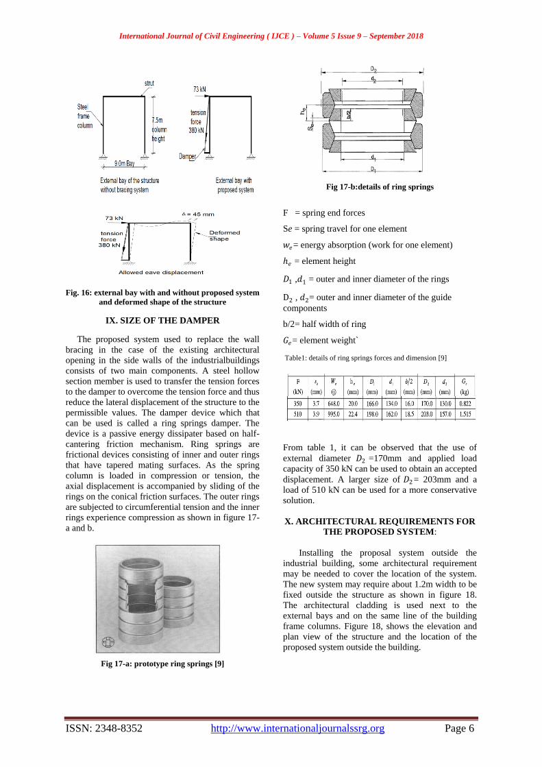
permissible values. The damper device which that
can be used is called a ring springs damper. The
device is a passive energy dissipater based on half-
cantering friction mechanism. Ring springs are
frictional devices consisting of inner and outer rings
that have tapered mating surfaces. As the spring
column is loaded in compression or tension, the
axial displacement is accompanied by sliding of the
rings on the conical friction surfaces. The outer rings
are subjected to circumferential tension and the inner
rings experience compression as shown in figure 17-
a and b.
Fig 17-a: prototype ring springs [9]
Fig 17-b:details of ring springs
F = spring end forces
Se = spring travel for one element
𝑤𝑒= energy absorption (work for one element)
ℎ𝑒 = element height
𝐷1 ,𝑑1 = outer and inner diameter of the rings
D2 , 𝑑2= outer and inner diameter of the guide
components
b/2= half width of ring
𝐺𝑒= element weight`
Table1: details of ring springs forces and dimension [9]
From table 1, it can be observed that the use of
external diameter 𝐷2 =170mm and applied load
capacity of 350 kN can be used to obtain an accepted
displacement. A larger size of 𝐷2= 203mm and a
load of 510 kN can be used for a more conservative
solution.
X. ARCHITECTURAL REQUIREMENTS FOR
THE PROPOSED SYSTEM:
Installing the proposal system outside the
industrial building, some architectural requirement
may be needed to cover the location of the system.
The new system may require about 1.2m width to be
fixed outside the structure as shown in figure 18.
The architectural cladding is used next to the
external bays and on the same line of the building
frame columns. Figure 18, shows the elevation and
plan view of the structure and the location of the
proposed system outside the building.

International Journal of Civil Engineering ( IJCE ) – Volume 5 Issue 9 – September 2018
ISSN: 2348-8352 http://www.internationaljournalssrg.org Page 7
Fig 18: View the location of the proposed system
CONCLUSION
In industrial buildings, the architectural
requirements of windows and doors opening of the
structure do not allow the structural designer for the
placement of the wall bracing in the outer bays to
resist the lateral forces applied to the structure. This
study shows an alternative system that can be used
to transfer the lateral forces from the roof bracing to
the base of the main columns of the structure. The
traditional methods of transferring the lateral loads
to the braced bays of the structure are expensive
because the additional struts are required to transfer
the loads to the braced bays. The proposed system
can beattached outside the external bays and the
lateral forces can be moving from the roof bracing at
the roof of the structure to the base of the main
columns of the structure using the proposed system.
The system can be located outside the structure with
the width not exceeding 1.2m as described in this
study.
REFERENCES
[1] Woolcook S.T, Kitipornchaf S., Bradford M.A, “Design of
portal frame buildings”, Australian Steel Institute 2003.
[2] Cement Concrete & Aggregates Australia, “Guide to tilt-up
Design and Construction”, Concrete Institute of Australia
2005.
[3] Australia / New Zealand Standards Wind Actions AS/NZS
1170.2: 2002.
[4] Saudi Wind Code – Loads & Forces Requirements,
SBC301-2007.
[5] Nagui W. Bishay, Athol J. Carr, “Ring Spring Dampers:
Passive Control System for Seismic Protection of
Structures”, Bulletin of the New Zealand Society for
Earthquake Engineering, Vol. 47, No 3, September 2014.
[6] John Holms, Andrew King, A Guide to ASNZS
1170.2:2002 Wind Actions 2005.
[7] MacRac Gregory, Clifton Charles,” Rocking structure
design considerations”, Steel Innovations 2013 Workshop,
Christchurch, New Zealand.
[8] ETABS Software, 2016, 16.0.03 Enhancements, CSI
Computers and Structures. INC.
[9] RINGFEDER GmbH, Friction Springs, Ringfeder in Mech.
Eng., Report R60E, Ringfeder Corporation, Germany.
[10] Justin D. Marshall, Finley A. Charney, “A hybrid control
device for steel structures” Journal of Constructional Steel
Research 66 (2010) 1287-1294.
[11] Amedeo Benavent- Climent, “A brace-type seismic damper
based on yielding the walls of hollow structural sections”,
Engineering Structures 32 (2010) 1113-1122.
[12] H.-L. Hsu, H. Halim, “Improving seismic performance of
framed structures with steel curved dampers”, Engineering
Structures 130 (2017) 99-111.
[13] Sang-Hoon Oh, Youn-Ju Kim, Hong-Sik Ryu, “Seismic
performance of steel structures with slit dampers”,
Engineering Structures 31 (2009) 1997-2008.
[14] VajreshwariUmachagi, Katta Venkataramana, G. R. Reddy,
“Application of dampers for vibration control of structures”,
International Journal of Research in Engineering and
Technology 2319-1163.
[15] Chandrashekhar B Adin, Praveen J. V, “Dynamic Analysis
of Industrial Steel Structures by using Bracing and Dampers
Under Wind and Earthquake Load”, International Journal of
Engineering Research & Technology, Vol 5. Issue 07, July -
2016.
[16] S.M Gledhill, G.K.Sidwell,” The Damage Avoidance
Design o Tall Steel Frame Building”, New Zealand Society
for Earthquake Engineering, 2008 NZSEE Conference.