A STUDY OF THE INFLUENCE OF GAS ON CAVITATION SCALE ...
64
" '. I· I· I (, ! ST. ANTHONY FALLS HYDRAULIC LABORATORY UNIVERSITY OF MINNESOTA Project Report No. 58 A STUDY OF THE INFLUENCE OF GAS . NUCLEI ON CAVITATION SCALE EFFECTS IN W ATER .. TUNNEL TESTS (With an Appendix, A Sonic Method of Measuring the Concentration. of Undissolved Gas Nuclei in Water) Submitted by LORENZ G, STRAUB Director Prepared by JOHN F. RIPKEN with Appendix by REUBEN M. OLSON February 1958 Prepared for DAVID TAYLOR MODEL BASIN Department of the Navy Office of Naval Research Contract Nom 710(20)
Transcript of A STUDY OF THE INFLUENCE OF GAS ON CAVITATION SCALE ...
"
'.
I· I· I (,
!
ST. ANTHONY FALLS HYDRAULIC LABORATORY
UNIVERSITY OF MINNESOTA
Project Report No. 58
A STUDY OF THE INFLUENCE OF GAS . NUCLEI ON CAVITATION SCALE EFFECTS IN W ATER .. TUNNEL TESTS
(With an Appendix, A Sonic Method of Measuring the Concentration.
of Undissolved Gas Nuclei in Water)
Submitted by
LORENZ G, STRAUB Director
Prepared by
JOHN F. RIPKEN
with Appendix by REUBEN M. OLSON
February 1958
Prepared for DAVID TAYLOR MODEL BASIN
Department of the Navy ~---------------W{lshington,-D.G.·-------
Office of Naval Research Contract Nom 710(20)

Reproduction in whole or in part is permitted
for any purpose of the United states Government

PREFAOE _-JIIIoIoIII """" ___ ....- /
Iv.Iarine designs with performance limited by critical cavitation /i:e f
an important naval problem. Design studies with performan.ce predictions /jased . ! •
on model st.udies in a. ca.v:1. tation.}~t.wme.!LhaV'e:.lbng been plagued with sl~stan-/ .'
;~'in~~V~~~~~:~~~!:t~::~~~!~:;~!wj~J~tf~\ii:i;r~t~:~:;:is given to ~ ~6~~t~~'iltnft tk~·,J~h~~k\~t~·~tsti6f3"'·'of tb~·lca~:{t;~tt~~O;U~{~i ,~q I:s£~i" i~j th8 (,uL ';"'.,j. ...... ·~,'··."N·I "All;!: "'''' 14.~Rio' .. ,.l:< .... .t'.· •. lV.4. .: •• <,(~!", .. ~. th··· .. ·'·,.:;,,,,··· ·., ... yh:h~.tf"K'';'''·'' ."j) ttl.
Q. ·:11e·o.'\,I iwa .. {;JS'",,,,:, . ·J,J.·l·le·'·matJ"'''' "'''''''''''/l:.p''''''{J ····Ill'~l,.I.er.· . . e·· .f,;II·d>gram .. 1~~""s'~·"1!Ieen "'(7 ,qen 0 ae
d~\i'J.en:O~~rJ@1trr'~m'rlla !ia.·.ew;l':ty:p(;).e~id.'ttt/E!if$ti;'$. ·ac§':@:'it,y~O .,rm~~·.Jd. a.·it.la Iftofuttl1.~'713/A.xh[.":.!t.'iJtl;.~'")ar§~:( st:tttl jpr1t:t::tml1'1a't-;r~'1;;fi :n~tlif.'iJ)~but~· f.tiV'&~iij!:i:romi\~e·l' O~::l cbrlt,~if>1lt'ihg "of.; 1sHe':"r&iauetfe11 of\tM~1~c~fl!f!)e.ijf;s~i;1·o8'l':tf.) 2;11!.:)EI oJ< ';.'ld'I1:d<b:j'n()~) '("£,,,;1 J1.0J:J']:d .. cdu.i: :rl A ~h:.d;:l- bfm 8rOD
, I. . .~iflj~ The studies covered in this report were carried ~ ~ in the period
ff;oJi (j)rett\i~f,!:pd:~~~ :lif1!P(i)ij,gh:::~Fe~r-iliir,J:1·9~(~!le:b~·Iwt~r'e£"'$:@0n%~a~e~1·!~Jf:"f,h@rli)av:i.d Taylor· Hodel Basin unde~,·)(jj5ntf:l&1i:tnNo:fu?.ItmO(!!1G~ .10 eUID8s'JJ{ (!Ifij' <.d':o<I,:b,T.O!.) hac 6(;!,j'OI1IO'JC;
!9!tn:r.r j' wW-lie0f11fli. t'M@r~::,~:b~'Yi1'lid4ibt~(:i[£ t1i:) M~tr(M:'I:Mi!l 'X;Rl1I~)gij~%.kIJofJIol'J?9:..q§.t J(~rlWeing arden,
Gutl.11e "v,JIsl?i::'iteks!;I:n, ba;l'tdJ:Cl~t>!I! EI1otllfjl1ii!taJt:;·~ lIi'tlW' ;e11~D:.;i1r'1~'09.'ltj1,$Jj'lft~oN~ .lbeFh6Ff{f3"J§tud;Y'·~. , \
Special acknowledgment is due John M. Killen for his roany·~6!8~fr>fll!:f.;g~€ifis":{.:cW'
;ltl;te.,~inst:r.ur.l1e.l1't de.y.e..;I".o:om!2( );IT·;~''''·f.l·;' .• ,',..,. I.,.,., .• '. h,· ... " r< r .1.]." .,.l' .. I'·V" ,., "I"""~''+", "[gnP 1.<f ...... l:h.l.r.r.rJ;r 'lDJ]t)() :J./ ... r ,:\Sf;~ .:.J.~-n: .. jT\r~,\::h) ~.\.IIi~.hl.,'-'~\.I.I::"l\" _4 \u;:',,' .1.1 .... "".,to":I,')"" U Col\. \)O'J..J.v V.. '"-' A
Loy4i!llf.1Aild·J6h:ffStlftj·eel.tt§QEtl1e:'!mt:i'ft11i~~fl~i?tr.!Wiihfl:.~tJh:e':'.:a~:a:t§i;i!ff6~'a8frc1EtB@:t
H. Hansell.
iii:

ABSTRACT ----..,..-"-.-
The gas content of w~ter employed in a cavitation tunneJ.isknown
to irif'luence the· conditions under which cavitation will be init:t$.ted •
. This st~d7 gives e~pbasis to the importange of the portion of the
gas· content which i~ in the 10rm of i'ree":gas bubbles. It is shown that .th~se cavitation nucleiare:tllhibited from forming in existing- types of water tun
nels and that suchinhib1tion may contribute to scale eff'ectsin model test ...
ing. .1. ,_,
The report describes a new modification to tunnel construction that
·promot,es and controls the presence of gas nuclei in th~ water'o
The increased ooncent+,~tions of nuclei provided by the new tunnel.
were evalUated by avetr J)r~is~g new. instrument developed specificaily for
such ~aSurementsc
Scale etfeets evident in cavitation ... ineeption't.ests in other' tunnels were ,eubst.antialiy- reduc~d in ootllparable tests inthe,tu9W tuime-1..
i;~: .'

Preface • • • '" • • • .. "' • .'" • It ..... .. •. .. t' ;. ...... • e· .. • • .... •
Abstract .. • • •.• • • • .. • • • ••.• ".' • " .. ...... • ... .. ".!" " • '. ~ist of· Illustrations • ••. ••• .. ~ • • ,. '" ,,' .. .. • • , .. .... .. ••.
Page
iii' ~v: v:i,
I. INTRODUCTION " .. • • .. • .. • • .. .. • •. '" ........ •• • e.,' .. 1
A . RESUME OF OURRE.NT OONOEPTS' ON THE INFLUENOEOF O-AS OONCENTRATION H" .. • ;, ;, .... .•.• .. ..' .. ~ ... .. ~." •• '" • I . . . II '"
III. GAS ... OONTROL DEFICIENOIES OF EXISnNG ¥IATER TUNNELS. • • • • • '" ? .
IV. A NEW FOmi bF WATER TUNNEL ...... • .. ........ '.' " .. II • •• 7
. V. A NEW FORM OF NUCLEI ... OONOENTRATION METER .... "., ....... ..,: ... " .... VI. CAVITATION TES+'S IN TBENEW WATEll~_L .. " '" . . " '. .. .. '''. ,. ,
VII. CONCLUSIONS '" ... · .. • • . ~ ... • .,. t. • • .e • .,. • .:.. .. • t ....
List of' References Figures 1 through '7
..
.. .. •
• • • .. • • e· .. • .. ." • .. e .. ~ ~ •
.. • .. ;; .. .. .. ... 0 • • ." • • ",. .. .. e ,
'"
Appendix A - A SONIC }1ETHOD OFl-IBlASuro:J:fG THE CONGE~RAT~ONOF
e· • .. .. .. e· .'. •
UNDISSQLVED OASNUC~EIIN WATER. .• ' ........ ~ ........ ' :. "
I. INTRODUCTION • • · .. . ... ". . '.. . . . ..". . ..
1.3
1, 22 '. I
24 27
. .35. .'
·.35 .
II. THEORY ... .. • •• ..... • .... • .. .. •.• • .. .. • .••. .. .. • .. • • .3,.,
III" BUBBLE SIZES OF INTERES'X ..". e .. • .. .. • ... .. .. •• .. • • •• .3.8
IV. METHOD OF MEAStJREMEN'l' •• •. 4O . " .' .. .. .. . .. . • ••• • .. . :. ... " . .
V. PRELIMJ;NARl'. MEASUlUGMENTS IN. OF'.ENWATER AT RliIST .. . .. · " .. VI. ADAPTATION TO WATER ... TUNNEL M$ASUREMEmS. • .. .. .. .. ..
!J. '.- · ~ . VII. SUMMARY ..... ..... · ..... .. <i " .. . .. .. .. . .. .. .. .". . .. ~ ... .List of References ...... .. .. .. .... •.• .. ..... • .. .. .. • 0 ., .... . ., .. Figures A ... l through A-a .. ... .. • .. •• .. .. 41 .. .. ...... .. .. .. •. : .•. ,'1 ... It
Distribution List .................................. .. • • • • • •
v
.39
~
42
~
44 47 55

Figure
I
2
3
4
5
6
7
A-I
1\.-2
A-3
1\.-4
A .. 5
A-6
LIST OF
Relation Between Bubble Size and ,Superimposed Pressure as ' .. Influenced by Gas Content of the Bubble (From Reference [4])~
Configuration of Gas ... Separator Tube Empioyed in Tunnel Tests
General Arrangement of Separator Tubes in ~unnel·Cross Section as Viewed From Upstream ~ • 6 0 0 & • " " " • • .. 0 •
. . i •
The 6-in. Water Tunnel With Gas •• Separator Modifications " • 0
Arrangement of the Two-Dimensional Combined Turning Vane and "Fiow -Diffuser .' .: Ii' 0.;' .. 0' • .. , .•. I) ,,' 0 '0 ,'·0 (I ~ " ,(t (t.. 0, • • 0- • ..
Relation ·Between ,Incipient CaVitation Index and Test .. Section Velocity for Various Sizes of Hem:isphere and i.5-Caliber Ogive Head Forms (From ·Reference .[10]) , 0 ...... " ••••
Relation -Between Incipient Cavitation .I.ndex and Test-Section Velooity for an O .. 5-in ... Diameter,9 i o5-Caliber Ogive Head Fol"Dl as Influenced by the Gas Content of the Water. 0$ .. " " • "
Reduction in Acoustic Veloci'ty in Gas-Water Mixtures o • • •
Effect of Pressure on the Reduction in Acoustic Velocity in Gas-Water Mixtures .". 0 " • ~ 6 ,. • 0 • 0 " " .. .. " 0 • •
Resonant BUbble Size "at Various Frequencies and 'U-Iater-Tunnel Test-Section Conditions for Various Cavitation Numbers ... ..
Pulse Circuit .. .. .. .. " .. .. "0.00 •• o 0' • • •
Oscillogram of Wall's Form • & • GOO Q 0 • 0 ~ 0 000 0
.. Oscillograph Traces for Direct Measurement of Transit Time of Aconstic .Wave • It • .. .. 0 • .".'0 ... " ~, " .. .. • • • .. .. • • .. •
Oscil1~gra,h Traces With Delay Circuit b 0 • • ~ 0 0 • • 0 4
Measured Gas Concentration in Nuclei in Open Water at Rest at . Variou_sIn~tants A;f.'ter"Stlp:ply of Nuclei Wal3 Cut Off ... " ...
vi
Page
27
28 ..
28
29
)0
, 31
.34
47
48
49 50
51
51 51

! ~! £!2 ! Q!.. 1:!i! 1 !!~!t!!. ~li Q.! 51!. 2! §. !!!. ~k!l 2!. Q.!!t~!!!Q!i ~.Q.!!o.! [[~!Q.!§. !!
WA TE R- TU NNEL T ES TS -- ..... - ..... ---....... ~-- -,.....- .... -, .' "
I. 'INTRODUCTION
The designers of dyn8.mic hydraulic machinery and' underWater 'bodies
have ;tor many years:regarded the cavitation tunnel as a primary facility in
the dete:rBd.nation of the perfol"Jli.ance criticals established by the occurrence
of cavitation in a' given design. The effectiveness of, these facilities is
attested to by the increasing number, size, and speeq'of the new uriits of
this character which are being built to pursue cavitation st'Udies, both here
and abroad"
These faciliiies 'have been mo~tusefui in those hydraulic fields wb,ere the ~ize and nature of the prototype ~ke it economicaliy" desirable "~o conduct design studies on' a model "scale., This is particularly trUe in t~e' study of large m~rlne pr~peD.-ers,imde:rwater ,ordnance, and Ivdroelectri~ t.urbines. 'In ali of these fields there has been a' continuing effort to improve' the relia.bility 'Of the model'studies as an index of prototype performance.
However, despite this effort, significant sources of error stiU remain in the
res'll1ts obtained from cavitation studies in water tunnels.
While there are many tUnnel enviromnentBi' conditions which are known
to differ sigrnf:tcantiy from the prototype, variatioriin the gas concentration of the tunnel water has ,long 'been suspeoted as a'major eontrlhutor to predi~-
. tion errors relatitm to incipient 'cavi tation f3tud:tes.A numper' of studies [i ~ * .... ,.. . .. ,.... . . , . : ..., ,. 2, and :3] have. been made of the ini'l-p,enoe of', the gas content as measured by'
the dissolved gas. These studies have ind:t.c~t~d that'the dissolved;'gas concen":
t:;ation is influential put is not in itself a sufficientlY reliable index to
c&v1tation suscepti'b1iityo More recentlY it has been conjectured that possibly
olliY the entrained, f:ree .. gas nUClei in the flow are important to the modeling
of oavitationinception~
*Numbers in brackets refer to the corresponding numbers in the List of References on pa 24.

2
The atuqy described her~inwas initiated on the premise that eavita
tion-inceptien tests inVoiVing water enriched with many nuclei would be signif
. icaritlY dl.ff'erentfromtests il'lVo)'Y1ng water depleted of gas nuclei.
Proof of this premise ml13cessitated the d~velopment of apraet:tcal
tmmel .t'ac:i:.litypermitting subst~tial controiof the nuclei existing in the
tttmlel flow and the development ot a meter to evaluate th~ concentratfonof
nuclei-These developments are <iescrtbed.
Cavitation-inc~l?tion.~e¥Jts ota prel~.~nary nature wereconc\uctedin the newt~i" Wi~ha~e~' . '£ri~·r~~a~~e~e:riti.'6ft~~~nuclei concentration.
The teSts iridieate a Stlbstanti.a.1· ~eductionintb.e, seBJ.e effect apparetit'in . !
The groWth of vapor or gas bubbles in a liquid under varying Qondi
tiona. o:fiemperature, pressure ,and gas concentration has been the s'\l,bject of
considerabie study over along period of time • If one examine.s the literature
of these studies with" a view' toW~rd clarifying the basic mechanisms involved
in the cav:lt~t:i.on~illeept10l). process~ c~rtain obscurities and acceptable con .. '
capts appear.
The follOwing important points appear to have a bas:ts in demonstrat ... abie concepts:
l~ water which' is gas',tree and at temperatttres common in nature
has a' substan,tiaJ. fesistaneeto interruu "'ttmsiie . rupture' or
to' being pulled free from a sciid'bom1dary ..
2. In 'gas"';i~e .water; ioe si stance to tearin~.forees is suffi~:'{' ,
cient to p;reVent ca.vitation under the limited nega.tive . pri;HSmlre values normlD.ly found :i.ngood hydrodynamic d~s:igns.
3.: A!reesurfaee or gas-iiquid interface wi thin the l1qu1d is essential to the" inception of c~vi tation.. The interface
'may exist as' a gas bubble either entrained in the liquid
or trapped in a fissure of the solid boundary.. Natural'
waters give evidence of having Substantial numbers of such . discrete free 8urfacesor . nuclei ....

4. Cavi'i:,ation. or the large-scale growth of a gas nucleus
under reduced pressure conditions occurS either as the
result of the diffusion of dissolved gas through the
interface and into the nucleus or from vaporization at the interface,
5. In most hydrodynamic design problems, the bulk of the flow, .,
stream and its entrained nuclei are exposed to reduced pressure so briefly that the slow, gaseous diffusion proc
esses are unable to contribute materially to the nuclei
growtli. The resulting gaseous cavitation is therefore of
minor importance.
6. Vaporization at the nuclei interface can and apparently
does serve as the principal support for rapid growth or
true cavitation of the original nuclei under reduced pres ...
sure conditions.
7. The gas nuclei in the water are directly involved in the :i.nception of cavitation and the dissol vea. gas is only
indirectly involved.
8. A large number of factors contribute to initiating and
supporting the rapid" vaporous growth of a nucleus, but
chief ,among these is a critical balance between net pres
sure forces across the interface and the surface-tension force in the interface. Because of this latt~r forcy, the
inception of cavitation is dependent on the size of the
nucleus when it enters the region Of low pressure.
9. The stable size of a gas nucleus under a given condition of sustained pressure in a given liquid is dependent on the
dissolved gas in the liquid and the previous history of
pressurization.
:3
The concepts involved in the last three i't,ems constitute the basis
for the investigation described herein. Important to the understandi,ng of: --.. ----- ---- -these--Uollcepts-is- the-follovr.ing-rationalization.----------------------------------.--
·The element~ static equilibrium conditions pertinent to the expansion of a gas bubble in a liquid have been analyzed [4) to yield the expression

4
p + p .. P .fllI 2 ug. v l'
or
I{. u-p ... P 113 ---.. _. 2 -
v 3 l' l'
where Pv is the liquid vapor. pressure, p is .. the ambient liquid pressure,
p is the partial pressure of gas (which equals K/r3 for a perfect gas at
a g constant temperature where K varies with the weiglit of gas in the bubbl~), u- is tmit surface tension, and r is bubble radius~
If arbitrary values of K are selected together with a tyPical
u- !!II 0.005 lb per ft for '!irater at 68 F, the relationship between the pressure
differential p - p . (expressed in feet of water) and the bubble diron.eter has . .. . . ..... v ... . .
been calculated [41 to be in accord with Fig .11'1
The idealized differential pressu:J:'e values shown in Fig~ i nay be
only a qualitative approximation to the reIa'hionship for cavitation under
dynamic conditions in a water turmel.. However, the figure is importmt in
that it shows the way in which pressure must be lowered 'co a crit.i~ai value
before the rapid expansion of true vaporous cavitation can be experienced b,y
a given bubble. This critical eXpansion size is approximated by the dashed
curve of the fig~re0 The plotting demonstrates that rapid vapDrous expansion
or cavitation will readily occur at moderate differential pressures if the
nucleus is relatively large but will occur only under very low pressures if
the nucleus is very small" The :plo-~ting also serves to dem.onstratethat the
usual method of writing the cavita-~ion index is erroneous if vapor pressure is
presumed to exist in the ca-v-ity <>
It is apparent from these pressure curves that the value of ' the cav
itation parameter for inception conditions ona given test body should be dg ...
nifieantly affected by the size of nuclei available in the test water" Ii'rom
this itiol10w8,that water-tu.n:nel studies of incipient cavitation on a model
wiil produce a reasonable approximation to prototype cavi~at~~m only if the
nuclei are in S41>me way comparable. If wide dissimilari"tjies exist between
n'U.~iei in the model aI).dprototype, it is reasonable to eXpect disparities or
Uscale eff'ectsll to be in evidence in model-prototype comparisons.


6
are produced by use of. a high flow speed. In the case of rotar,r blading s,rs-.... , .. ,
terns, the lovT pressures on the' blades are produced by the through flow aug-
mented 'a,r the velocity of rotation.
$inee the cost of operating the tunnel val'ies as t,he cube rfJ£ the
flow speed, and the .loads imposed on mod.els' vary as the square of the speed,
it iseeoxiOinieaily desirable to eonduct cavitat:1on.Dlodelstuciies at the lowest
permissible speed.. Use of. a fOlf. speed requires,' in turn, 'the use of a low
ambient pressure for similarity i~ accord with the conventionai cavitation
parametero.
In the eonventiona1l1Tater tunne19 which l'ecircruates the test water
in a closed cOllduitloop, the test speed:i.s usually independently controlled
through the pump speed~ and the test-section pressure is independelltli varied by
sUperimposing static variations on the entire "Immel loop. 'l'he establishl'lient of
a desired test .... section speed and pressure is ·therefore quite straightforward.
If'~ in accord with th'e foregoillg discussion on nuclei, one decides
that it: is also desirable to control the size of gas nuclei present in the
test seetion9 a new oomplication is introdueedo
Gas nuclei in a given liquid. increase or decrease in size in accor~
with the dissolved-gas concentration of the l:i.q'llid and the ambient exposure
pressure.. Under steady test conditions, diffusion processes continue mtil an
equilibrium condition stabilizes the size of the nuclei,. ,Brown [7J found that
the rate of ohange of mClei size was quite rapid for a sUbstantial; ovsrsatur ...
ation or undersaturation condition a.rl.d. asYmptotically approached a stable size
as saturation was approached.
This meanS that a water saturated with dissolved gas consistent with
a selected mean tunnel pressure must be mafnta:tned if' nuclei are to be stablY
maintained ..
If a tUnnel water is sat'l1.I'ated With dissolved gas for a given mean
pressure condition and plsses through thS low ... pressure test section, eii entrained.
nueleusw.ni:incraase localiy in size and decrease again as it passes into regions
of higher pressure:in the tlumellcxp. if this repeating cycle of' expansion ~d contraction is augmented by heavy cavitation in the test section, the combined
mechanism appears to afford a coaJesence or co1i~etion of nuolei into larger bub
bles which may- not 'be able to return' to nucleus size in 4!\1. single pass through
the tu:nnelloop. A"oontinuation of this progedure may ultima:l;el;y result in a

7
new stability pattern which allows substantial numbers of larger bubbles to
recirculate in the flow~
In the practical operation of a water tunnel, these recirculating
larger bubbles constitute an obscuring abnormality in the flow and it is
desirable that they be elim:l.nated ..
If en attempt is made to mainttrl.na dissolved .... gas content consistent
with normal atmospheric saturation, larger bubbles w:iJl usually appear in con-'
tinued tunnel operations .. This happens with a conventional water tunnel because
the circuit time, for 'Wh:i.ch reabsorbing high pressures exist, is too limited
to achieve complete reapsol'ption~
In the case of the simple tunnel, the undesirable accumulation of
large bubbles can be alleviated by reducing the dissolved-gas content until
the undersaturation inhibits the evolution of the bubbles and accelerates
reabsorption sufficient to acoommodate the available time-pressure qrcle of
the circuit.. For tunnel studies involving light 'or incipient cavitation, the
necessary 1lndersaturation may be quite moderate, whereas with heavy cavitation,
theundersatilration must be substantialo , Unfortunately, efforts to undersat
urate for the eiimination of larger bubbies wili eliminate quite effectivelY'
ailbutthe smal.lest of the n~J.Clei and will, in tUrn, adverseJ.;rinfluence a
subsequent 'critical expansion pressUre in accord with'Fig. 1.'
In the case of the dal Tech resorber tunnel, a. remedy is provided ?y increasing both the til'lle and pressure in the ,return circuit su:tficiently to
:reabsorb the offending larger bubbles~ Unfortu.natelY, the high pressures
neoessarytobrlng the larger bubbles under control wfil, leave only very small
'nuclei and will a.gain adversely influence the crt tical expansion pressure in
accord with Fig. 1.
From the foregoing; it is apparent that oavitation studies in exist-. ,
ing types of water tunnels will generally be involved with either excessive
numbers of obscuring large bubbles or with a deficient number of suit.able
nuclei 0 In either case the model'inception test data may be conSidered some
what a.bnormal for use in prototype predictions'"
The problem of providing a tunnel flow that contained a nea:r normal
or controllable content of nuclei without the presence of large bubbles ~~;~

8
evident:t.;V called for a material change in the physical make-up of existing tun
nel types. .A review of thetotaJ. problem indicated that theprobiem of provid-:
ing .. suitable nuclei might be soived if m~ans could be found for screening out
or separating only the extraneou~ large bubbles from a tunnel flow with other
wise satisfactory control.
The problem of mechantcally separating gas bubbles from the flow in
a water-tunnel test sectioncoul.d conceivably be approached in a variety of
ways. HcDwever, tht1 solution of t:j:tndlar gas-separation problems in other tech-. . . ", - . - . )", .. ' '..:":. . ... ,. ' ' .. " ,. '>', .~:;<.-~,.:., \ . " '," . - : .'.' ',' ..
meal: ;fi~ld$\;a\:p:peared:':±ni"'hec:,'pra:Q"bt~*l?p~e(!!~~<,>"em:pl.ei'either. gravi ty 01'· een-trifugal force in producing the dElJdred result" 'rhe'applieation of a centrif
ugal force might produce -a powerf1l1, rap:td-acting separation suitable toa
sma.ll insta.llation;: bu1;:with' the: large:t+w vcDlimle mvolwa fu a water:, iillim.el., centrlfug:tng did not seem apraeticBJ. solution. The ·problem', therefore,
resolved itseii into consideration of simpie methods of gm:rl.ty separation.
A stuctr of the'iiterature relating to the gravitational rate of rise
of individual gas bubbles through water indicates thai the rate of rise varies
from a small value ('0.0075 fps at diameter .. 0.001 in~, 0 .. 075 fps at diaJn.eter =
0.01 in .. ) toat~n.mina1 value near 1~0 fpsfot' bubbies with diameter .' 0.10 in.
or larger;. The initial design of a practicrugravity separator then requires ,. . :.'. . .,. , :" .' .
a selectl.on of that size range which is to be passed and that which is to be
retained. The size of bubble to be passed by the separator to serve as test.;..
section nuclei has bSen discussed previously.. No pretemd 'top sfm 'of n-o.cieus
has as ,etbeen est;'biished,but a ixumbsr of fihtors :tl1dic(rte that it ~o-nIdbe' desirabie to separate bUbblesiarger than about' 0 .. 01 inches in diameter.
From the above figures, it is evidtmt that the simplest type of grav.::i. ty sepiu-ation using ~ vertical dmmflow tank would require' a flow cross .. '
.sectional area .and associated diffuser conduit of very large size'~
As an alternatet 0 separation iIi a vertical dOwrirtow.t it was ration
alized that separation of gas bubbles eould be accomplished bypassing the
flow through a 'bundle of sIIlali bore tubes in til. near-horizontal position. The
vertical rise ra.te of the bubbles would permit them to ascend to the tops of
the tubes as the water moved axially through the tubes. The gas would then
a.ccumuiate at the tops of the tubes where it might be 'Wi thdra'Wn by secondary
gravity effects or other means. Since the rise distance could be kept small
by use of tubes of small height, collection at the tube top could presuinably
be accomplished in a relatively short flow length.

I • ,"
9
The tube diameter and length req'lrl.:red to collect ail bubbles above
a ce:rtain arbitrary size may be calculated s:tmply by using the previously me~~ tioned rates of rise. These simplifiedcalculati~ns do not, however, account
for the'diffusion or exchange characteristics of the fluid turbulence 'Whichme;r
produce forces dominant over the gravitational separating force. The result of , , '
these forces and other secondary forces will support a stable state of suspen-
sion of' bubbles helow a ce:rtain cr:ltical size II Accordingly ~ the crl tical size
ofbu'bbles which wili pass through the sepal'ator will be dependent not only on
'the configuration of. the separator tubes but also on the inherent turbulence
of the approach flow system. Since the latter is not, i~ practice, subject to
close controi or analysis " it was decided to establiSh the design of the separ ..
ator structure on the basis of experimental studies.
A conventional form of water tunnel of 6':'in" test-section diameter
was available at the St" Anthony Falls Hydraulic Laboratory" The character
istiCS of this tunnei were well known from prev'ious cavitation studies and the
tmmel was easi~y' adapted to physical modification. In light of this, the
separator development program was designed around, use of this tunnel.
Selection of the configuration of t.ubes to be tested represented a a compromise between those Which might be preferred for flow 'controlBn.C1. fu:bse
which could be practically fabricated for mass 'installation in a water tunnel.
Those configurations which offered promise of development were fab
ricated to prototype size and :in a srnall ... tank test setup were exposed to' gasi
.fied flow conditions approximating those to be expected in the tunnel. , . '
These comparative ,tests eventually lead to the selection of a flow
tube with a crown shaped to a sh~u:'p; inverted V in which a. greatly thickened
boUndary layer develops. Bubbles, which manage to gravitate upward into this
boundary layer within the length of the tube, are exposedto relativelY low
vel60i ties and a weakened transportingsystem~ Wi th the tube axis tilted down
ward :in the direction of flow, the bubbles collecting in the crown of the tube
Will be subject toa gravitational-force component acting upstream along the
top of the tube.
With appropriate a.djustment of the tube slope and the mean flow
--veloci ty, it has been established that it is practical" to promote the collec
tion and upstream movement, of all but the smallest sizes of bubbles passing through the tube. To promo'lie general collection of the bubbles, the indiv:i4ual
_J.~ _'.,

10
tubes are pr'ov1ded w:lth hole:e; neal' the 'Upst,ream end. These holes pe~1t the
bubbles to grs,v1Jc,@,te :i'.mn onl3 tl,1Oe tt.l the next above 0 !n the case of. the. ,water
'\:,l1l.1.nel, the bubbles progresliJ upwaI'd throt1gh Jr.he tube stack to 'the top of . the
'cU1mel ~onduit '~ilhere they are ~o11e©-l:;ed and oh'aml off for disp0\!!lal or /controlled
:1I:'e-I.1I11'u to '!:;he ttl:l:m.(al ..
Pilot ~:)'tudier-l o:f· vl'l.l"iou$ tube co:nf:igurat:t<OlIll5 and arrangements lead
to use of standa:r.d9 galvanized» co:r.T·o.gated r:d;,t~el sheets sta4!ked to produce: the
desired t;ube a.l'l'alJ.gem~~mt iJ as shciwn in. Figs. 2 and 3 0
The pilot S·l:,li.d.1.ElS sho'siTed tha:t a tube length of 3 ft, ha:ving a. tube
sJ.,ppe of ,abo~;rjJ 20 d.~g-l·ees w.H:;h th~~ bm'''i2.jontal and a meanvelocit,y o:t'not more
tb.an 10Q 1:1'13 ~Nould collec"t s·UbStB11·t:L~1.11;y" 8J..l of' ·thf; bllbbles larger than about
0,,03 in©hes in diamete:r'., 'While it, wOl"l.1d hav~) been desirable 'bo reduce this
m:i.Y.limml1 s~~p;aril:t;:i()n V,",uXtl3 -GO ·the pr\~.f'el"Jr'i:!d 0 tlOl-ino=llr"aximuJn nucleus size, the
higher valll~3 appe~lred to be a p:lf;ac·~:tml1 limi:G"
'l'he sepe.ratol' t'1.tbil1g- of' Il'igo :3 is introdllCt"ld into the circuit of the
·tunn.el 113. ·'the 10w=Vi'~lo©:i.'1iy reg:h)n up,':rt:rceam of' too ,,~ontl·action.9 as shown::1.:p"l!'igo
L.. At' the dOW'1i.r::rl:.re,am end uf'the sepa:1C'a"IJor,\) 1::1 ,flow-straigrr\isning hOIJ.eyoomb is
pro;T:1.d('ld. 'I'his honeytl4Jn:ib,9 of i~hj.l:J. sheet mei;al" its composed of Ct311s of about
l/h ·l:nch. in diruneter and .3 lllches in le:ngth 'Iluth ai'.:E~B parall<31 to the tunnel test ~>~Jit~t:lo:no 'J:'h:l.:!I S~:'lrln'3S bo·th illS ill, fiow str£:'J.ightener a.nd a turbulence sup...,
prelSSOl"" The f'llCfW straigh'l;(3l'&r is follO'~ied by a (j(Jl:'l't;ra~"ion approach t1hamb:er
"Vlh:tch ~U101rr8 sO.me tm-bu.iencG de.eay in the r].Oli~· lfJf'rn:>El entrance to J'c.he contl"ac
t:Lon"
The contra.ctiOlrl :1.:6 a q:a,®.d:if:'larrt of a:nel()ngat~3d.i1 simple elJ ... ipse designed
to be free ot cav1:t.8.tion J.n a:r~cord. ~1ith Ref'~irentC!e [8]., This fo!'1ll. :r;ermits a COlll
pl,).~t~e,;\onomi(::al Ct:m,stl'lllCr!ii,01(l 'nth e:J1.:cel1e;crt .i'1<ow properties and may be ·safely'
e:mployed beCa'llitle 0.1' ~l;.he la1c-ge ~.l"e<9. :t'.e;ti® :.1 .• 1'lVoh'ed in the cmrtraction" In mod
i.~r'llng; thif:l 6,,,<1.110 tunnel.ll i~he contra~~t.,io:n WSlJ!l f'~bT:i.tCat:ad of I,uciteo
The low "W'clt)cH.y :J('eqLu:rced in the aepaI'.a.to:r 11EtCessitat,ed substanti.a1
vell.'Jeity reducti(.m in ·the port,ion of the tu.nnel ©irC'ilit fol1owl:ngthe punip~
'1'11i5 'vell()city :reduct::iA)n is i':i.x(:3d by 'I;.he ma.:ximum telr:r~ ... l';lec;i;io:n velocity for which , . bl1hble-.f:1!.'ee· opl!:)ration is desired a~l COlllpal"f.ld'&o them:t,1x::'Lm.um l .. O· .. i'ps velocity
"IitThich :m.u;st prevail. i.1'1 the sepa:r'at.~'):r" In the Oa£l(fr) of the 6-1.n" tunnel "(-'he
raM.o ~ifas selelCJt:ad l\\1!3 32 0 Th::lL~':1 'wa>i3 selected ·G.; allm.r sub~')l:,antin1 rnYE)l'.'load test .
. s'i;.ud:i.es at 'l-;he top 'Iim~AM~1 speed of 50 fpso

11
The fomi. of the conventional ~:i.n. ·tlll'l.n.ed.,9 whioh was being modi.fied ,. " .,' . '. • : .' . I " .,"'4
for this stu.dy, provided an excessive velooit',r in the :region in which the sap ... '
arater was to be instalJ.edand necesdtated 'hile proviSion of additional dii:.:.
fuseraction employ~ng' 'an' 8.l~ea increase oi' about 4. This diffuser ra:b10 'W~us very iarge in relation to the va1ues usua11yencounier'ed in diff'use:r design
practice and necessitated a new concept in d.1,ffuser design in an effort to
'achieve economical const'ruotion and desirable flow characteristics 0 A st'U.dy"
aocompanied by tests was nk'ide on a ntU1lbex' of. d1~ffuser forms!> This finally
resulted in the comb1.tied t1U'n~.ng ,rane and t.wo':'d1.mens~:o:ru:il . di£f'use;r arrange':'
ment shown in the upper lef't":'hand COl'ner of Fig. 4 and detailed in Fig. ;;. This di£fu,ser provided a compact .arrsngement, with relatively good
characteristics, but as with all diffusers some maldistri'bution of velocity
developed on the discharge s:lde ~ Since a110nuniform velocity entering the flo.w
separator would lead to local bubhle tl'Hnsport i,n any high-velocity region" an
adjustment pf the veloci {r profite was neCt~Ssal:'y ~ This was' accomplished by
experimental .fitting of suitable !'esistance so:reenil'1g aoross the entrall(~e to \
the'turning vanes and the entrance to the sepa;t"atol~ tubes.
Th,e arrangement shown in Figo 4'provided a flolll ilrhich was visually
bubble free at low velocities and gradually sho~ed lU01"8 evidence of test. ...
sect.ion bubbies as the velocity increased~ . HOI~(:·!ii'e:r.l> eir8Xl under heavy cav:tta
'tion and with velocities EJ?Cceedi.ng the E:epa:r.;ator des:ign crit,ica.1 by a factor
of nearly 21J' the number of test-section bubbles was' judged as not' being exces-
sive for most tyPes of tunnel tests.
The over-rui performance of. 't,he tunnel 'with the a.ir-sepal·at.or modi-'
fications shown' in Fig. 4 was q,uite satisfactory'.. The separator f'abl."ice.tion
introduced substantial new boundar"v' a.reas to the tunnel flow and addi tion.al
diffuser action; but because of th.e· low ahso1.U'te veiocities inv:olved,the m.od~ I . " . . .. . .
irieations gave no bu11( evidence of sign~icant energy losses.
Ahasic assumptiono.f the ant, ire program. was' that cavita:tion':'inception
studies with wateil:' enriched with rnalVtll.lclei 'W'ould be Significantly different f'rom tests with water depleted. of" gas n'l.'l.o1ei. To test this assumption, it was
then required that th.e timriel or the tUnnel procedur'es must' be modified to
______ -"a""s"'-sur~eL...maintenancf.L1)f_1.BXge-l1umbers----o;Lnuclei-in-t.he-fl(lw.~-----------
In the initial phases of the program, it was felt that the desired nuclei would have to be suppli.ed by introducing them into the tunnel through

12
a bUbble generator. In a stable equ:l-librlum cond:ttion, these nuclei would be
l'ecircU1:ated with an· origin at the twmei separa.tor and cottectionsystem.I!
an·eqtdiibrlma condition w:i.tha higher :m.uclei concentration were desired, addi':'
tional outside gas woru.:d have to be introduced at the generator, and if an equil
ibrium with a·lower, content were desiredt a suitable amount of' collected gas
woUld have to be removed to the outside.
In support of th1sconcept, a nuclei-generator development was undertakEm •. Severa! different foms of sil.E:iar~type generators were designed· and b'l1ilt ..
These proved capable·· 0:(' produ~1ngsub'stiantiai voltunes and controiied bubble ai~-·· ing but faiiedto produce the d~sired' smaller nuclei sizes.. It is be11eveq; that
additional development of a. genera.tor would ha.ve achieved the desired' ends. HoweVer, preliminary tests indicated . that even with a nucleus generator, a.,sta ...
ble high· level of nuclei concentration could not be:m.a.intained in·a.water Un1ess
a near,,;·satura-!:;ion content of dissolved g.s existed in the water. In view of
this, development of a nuclei generator was s~spendedin favor of a. parallel . .
study which established that pressure control" of the tunnel could irihal"antly
produce the desired nuciei.
The a.lternate method. consisted of depressing the tunnel pressure to
the point where the liquid became supersaturated wi'tih gas and gas avtiiut:tolll.
began~ The amount of freed ga.s could be regulated by the pressure. -Theabso
iute pressure at;whieb a desired nuclei concentration occurl'ed wa.s d~p(mdent
on the initial dissolved-gas content of the given water<>
The maintenance of a stable levei ~f nuclei concentration by such
a procedure would. be d:l.£ficuli :in a statio water 9 but the smail nuclei remained in sta.ble suspension in the· turbulent tunnel now and any change in· pressure
was .followed by ·a r~pid shift CLass thm\a minut~) to ,stability at a new l~vel of' nuolei concentration. This rapid shift to a new stability a.PPears to be i?- general. agreement with the time:'pressurization effects noted in R~f'erenoe
[3 J ~ nu.ration tests were not made on the long--time stabili ti of th.e air content of such water, but conditions were observed to remain constant for
the 10 or 15 minut.es involved:in each of the ip.eeption tests, which are d~scribed
\ la.ter" These observations were made in the tumtel 'USing a new type of' nuclei ...
concentration meter, which will be described later ..
Some complications result in appl:t.cation of this procedure because
the aVerage pressure in the tunnel circuit is not. vaIJ.'ied exclusive~ by the test~section pressure regulator but is also a function of the speedoThese

1------··. I
1.3
difficulties are believed to be minor once preconditioning and test procedures"
are properly established for a given tunnel.
Sinoe the above procedure appears to offer a means of providing the neoessary nuclei without ~ernaily generating them, some question arises as to what should be done with the gas that may be oollected at the separator. Act~lly no real problem developed in the ourrent inception studies because " the,,Poalesoenoe of bubbles in the test seotion was minor, and their colleeti(>n~ and removal did not significantly affect the measured stability of the nuclei concentration. Under prolonged operation or at higher rates of removal associated with heavy cavitation, the loss of gas would, however, eventually 'be reflected in the saturation stability and the collected gases should be returned to the flow to maintain that stability.
Some explanation for the relative stability m~ be found in the fact thatl the gas entrained as useful nuclei in the tests did not exceed 100 parts,. per million of water volume. 'In contrast to thiS, the volume of ,gas in solu-, tion is probably normally equivalent to no less than about 20,000 parts per million. With these values it is apparent that even a fairly rapid turn-over in, the entrained 100 ppm will not readily affect or exhaust the dissolved 20,000 or more ppm.
While a maximum, useful concentration of entrained nuclei of 100 ppm was obtained in the tests, it is presumed that additional tests using even higher dissolved-gas concentrations would produce still higher,entrainednuolei conoentrations.
For the current tests the physical removal of the separated gas was ach~eved by application of a controlled vacuum,at the collection slot in the tunnel roof above the separator. Control of -this vaouum oonstituted the ambi .. ent pressure oontrol for the entire tunnel.
I
V. A NEW FORM OF 'NUCLEI--CONCENTRATION METER
Recognition of the imporlance of gas content on the inception of ca."'", itation is by no means new. Earlier the dissolved-gas content was generally thought to be the significant measure of influence , whereas more recent think
ing gives emphasis to the possible importance of o~ the freed gas.
In support of the earlier thinking, considerable effort has been
devoted to the development of practical air-content meters, and a number of

14
types have' evolved :£01' measuring various eonrponents of the dissolved-gas con~ tent.. None of these have selecrliivelymeasnred the em.:rained gas nuclei. As
part of the present gas ... eontroi study', it was originally proposed to make pre-
liminarystudies of a nuclei~concentration metero , ,
Severai' general methods of' approach originally appeared to, offer ,
promise and these were made the starting point of a development under this
general program. The end reSl.1lt of :th:is development was an instrument which'
is described in detail iii the appendfx: attached to this report~ The gElnerai
features 01 this 1nstromellt arehrief.1:Y deseribed in the fo1ibwi~g.· ~... .'
The selected instrument employ-sa measurement of 'the changes in the
bilimo~lusofcOipres'sib:ti1.ty in accord with a suggestion 'by Eisenberg .I9]~ This is aec0mj31ishedby measuring the' ratio 01 the acoustic velocity of' a homo";
geneous ,gas-water :mixture to the aco'US"f:.ic velocity of water free of gas. This
rat1Q is' a sensitive function of the' nuclei conoentrati~n of the water.
The, acoustic velocity was in each case evaluated bi 1!'easurt~g . the
time. of transit of a. sound pUlse t~aveling through the test fluid between ~ S01lnd source and a iSotll:ld pickup ..
The sound source was a. specia.ny. designedmagnEr~ostriCtioritrans .. ·
ducer which emitted pulses having a seiected frequency <> The sO'Ul'id piCkup
wa.s 'a standard 'barium titanate cl,Srandc crystalo
The' pickup signal wa.ve wa.s 1mpo~d on' a. standard oscilloscope f~direct reading of the soUnd wave transit time/) The trace length wasamaasure of the transit tims() The ratio of the trace iEmgth in ga.s ... free water to the trace
length in the ,gasified test water served as the acoustic velocity ratio ..
Initial eonffnator,y studies of the instrument were conduoted ill a
static .• "vvater tank; iu lat~r adap'(ations t~ transducer i911d pickup were atta.ched
directly to the exterior of the tunnel test sectiono
The soUnd coupling bet_en, the selected inst:rument components and
the Lueite test-section wills was simpie and' effective, and secondary sO'\md
transmission through ilie walls was :found to ha.ve a negligible effect on the
sig~lo,Meas'1ll'ing the sound"':transi t tin19 o:f the nuclei-free water prior to
a test and tne ~ubsequent t~ansit' time for a~ selected flow conditiQn per~
mitted ready evaluation of the nuclei eoncentn:tiono ,The iact that th3se mea.surements could he made' instantaneously II continuously J and directly in the test
sec""ion without disturbing the flow made -the instrument very promising.,

For each frequenoy of' sound pulse, there is a certain size of bubble
whioh is resonant to that frequency; and the presence of even a few such bub
bles in the sound beam will seriously ~ttenuate the signal. In the current
pilot design of the tunnel, a few bubbles of the larger resonant size are passed
through the separator when the test-section veiocities aX'e in excess of ,30 fps.
These bubbles proved suffioient to destroy the signal for velocities 'above ,30
fps in the current tests.
Available time did not permit fabricating transducers of other fre
quencies, nor did it permit revision of the tunnel to eliminate extraneous
bubbles from the flow. Therefore" the sound system was moved from the test
section .to a submerged position in the contraction chamber where the influ
ence of extraneous bubbles was minor.
The nuclei":concentration measurements, -which were made as part of the
inception studies (to be discussed later), were 'thus actually made in the con
traction chamber. The test-section nuclei concentration 'Values were then cal
'oU1a~ed from the contra.ctio~ chamber readings by ass'Ullling the isothermalexpan
sion o.fa perfect gas, using the measured pressure drop through the contrElOtion.
These values are; therefore, considered as an approximation to the nuolei con-
centratio~ which might aotually have existed. . . .
It was believed that with relatively minor changes in the tunnel cir- .
cuit and transducer unit, most of the difficulties encountered in these nuclei':'
concentration measurements could be remedied.
VI. 'CAVITATION TESTS IN THE NEW WATER TUNNEL
The previous discussion has pointed out the possibility tha.t the
nuclei: concentration of a. tunnel wate):' m~ be a clue to' abnormalities in model
observations of cavitation inception. Accordingly, the;, tunnel described in
.Section IV, p:reced.ing, 'Was assembled to . provide nuclei control and the instru
ment desoribed in Section V and the Appendix was developed to measure the ·nuolei
concentration. It remained then to establish by test the extent to which nuclei
concentration influences cavitation inception or oontributes to seale effects •.
-')g:a.ny -cavlt-ation-t-estaliiightbe conceived-to demonstrate tnei-nfluence
of nuclei on inception scale effects, but a relatively simple yet informative
test procedure had already been defined by earlier studies. These studies

16
rIO] were conducted in the 48-in. co:nventional tunnel at the Ordnance Research
Laborator,r and the 14-1n. resorber tunnel at the California Institute of Tech
nology. The tests evaluated the average .conditions for the inception of cavi
tation on hemispherical and 1.5-caliber, a::x:iaily synnnetric ogival (a pointed
bullet shape formed by-:a circular arc of radius 1,..5 times the body diameter)
head forms for a range of sizes exposed to a range of flow velocities. The
tests were :run with a dissoived .. air c(;mtent equivalent to about half-saturation
at atmospheric pressure ,. The. end result of the tests is . shown in Figlj 6 which
, is taken from Reference libl.
It is to be noted that the figure contains a horizontal line repre
senting the value of the mininnIDl dimensiocl.ess pressurecoef:r:tcient{CPt~) for
each of the two body shapes" The Op. values had been previously measured ,., .tnJ..n . ' . .' ..'
in ·.honcavi tating flow at a high Reynol¢!.$ number. The lack of agreement between
the measuredCPmin curve and a measured incipient';"cavitation curve fora given
size of body was presumed to constitute a scale effect. It is apparent that
. on this basis marked sca~e effects do eXist:in the CIT--ORt tests, and this· same
method of gaging scale effects will be used in reference to the tests of the
new tunnel which is to be described.
For compa1"ison with the CIT-ORL tests, the st,udies of the new sepa
rator tunnel employed a 1/2~in~"'diruneter, 1.,5-oa1iber ogive head form" . T1~e
ogive was located at the upstream end of a 1/2-in~ sting placed on the tUnnel
a;x:is at the downstream end of the contraction& The sting was supported by a
spider of' three ~treaml:tned struts positioned 6".5 :1.n .. downstream of the ogive.
In the separator;..tunnel 'bests, the stream speed was varied from a
ndnimlIDl usefUl value slightly over 20 fps to a max1mumcbtamabJB value slightl.j11·
over 50 fps. During cavitation tests the test pressure at the tunnel aXis was
varied from about' 2 toll ft af'water absolute by the appl:i.~ation of controlled
air pressure at the crown: of the sspdrator chamber.. The d1.sso1ved":gas content
of the water was varied by a preconditioning procedure"
In the case of the lOwest diss61ved~gas content, the ent:i.re tunnel was
subjeoted to the highest obtainable vacuum for a period of several hours. The
gases evolved under the vacuum gra\\d .. tated to the top of the tunnel and were
removed.. The vacuum was applied to the ttmnelwater at rest, but periodical1ythe
tunnel was run at a high speed'to produce heavy cavitation and gas evolution~
It is noteworthy that even after four hours of exposure to III high vacuum, num'"
arous sma.ll nuclei coUld be seen .forming and riSing in the water. There was

17
6'vidence of leakage of ai.r into the tunnel at joints and packingl3. so the evac
uaUon p:rocess 'was clisc:ont:l.nued af'tar abo1.:j.t four .hours and inception tests were
t,hen rUl'). ..
An intermedia:t,e dissolved-gals oontent was created by exposing an air
dome at; the. ,top of the tunnel separator to atmospheric pressure 'while air was
bubbled through the l"i(;ing leg of the t'l1.nnel with the t,unnel operating a:1:. loW'
speedb The exposure lasted abo\l't two hours 0 The extraneous gas not absorbed
by the water was removed thl"ough the gas separator and recircuf.ated through
the bupbler ..
11 high dissolved-gas content was created by exposing the air dome at
the top ~)f the tunnel separator to a pressure of 2 atmospheres absolute while
air was again bubbled through the rising leg of the tunnel" The exposure last ...
ed two hours"
The above pX'econdi'tionings were terminated just prior to a given test
series ~ The teS'1;; sel'ie~ was then begun by establishing a desired test-se~tion spee.d ~usually 'bhe maximum) and then progressively lowering the pressure until
oavitation bncU1'red on the test body" The pressure was then gradually raised
until the cavity disappeared.. This was considered the critical cavita:hion
·:il1cepti.on condit:i,on., The critical pressure and nuclei concentration were then
read and the run repeated for :reproducibilityo The speed was t,hen changed to
the next lower selected setting and a new ca:vit,atio;n..inception value noted 0
This prog:ression was continued to the lowes"t speed at which cavita:t.ion could
be i:n:i:ti,att~d. In tMo of the sel~ies, the sequence. of tests was :rerun to estab'"
lish further t.he reproducibility and long"'term stabilityo
The nuclei-concentration meter$) which is, described separately in the
Appendi:x:, was mOUIlted near the top of' the contl"acti.on chamber" This meter had
two arbitl'a!:yr scales or sensitivities, but because of ::l:ts elementary form, one
of them had to be elected prior to a given r'lUlo Since large gas-corrl:.ent effects
were initially being sought, "bhe cruder, less sensitive instrument hoc)kup was
employed in these tests.
In each of' the test se:r.ies, the initial comparati'lle transit time evi
denced on .the oscilloscope waSl'1oted for the undisturbed but fre.shly precondi ...
---"---------t:i.oned'l-ratero c The-t.ram!i.t-t·ime on the-oscilloscope-was R.ea:in-readfor_±,he ____ ~_--
water condit,ion existing at. the time of an observed inception condition" The
ratio of these transi.t times could then be converted to relative nuclei-concen
traticn values in accord 'with the procedure described in the Appendixo

18
, It is to be noted that the test conditions in' general employed water
'which visually appeared to be free of gas. However, for those runs where the
nuclei:':concentration read.:irlg was comparatively high, the water had a definitely
cloudy or milky appearance.
The inception of cavitation walf~e:rVed visually in the low ... pressu.re
region orithetop side of the ogive" Forte'sts involVing low nuclei eoncentra.:,:
tion and 16'toTspeed,inception W1lS noted under rising pressure conditions by
the sudden disappearance of a steady ... state cavityhaving a clear forward portion
and a flDarnya:ttEl'riil'p:orticin;,,;Jrbt·;tb.~ive,riibi.testpresetU'eano. 'speed, the ineep ...
tion '~vity was as mueh as2in~, :long., Hysteresis was noted in the: pressure
cond.itions relating to the appearance and disappearance of the cavity at low
pressures"
As the speeo. and,p~essure of in.cepti.o~ li:ncreased, the steady incep
tion cavity shortened. in Ij:p.gt,h and the pressure bysteresis pr<?gress1.vely o.i"";'
minished to zero.
For the tests with the lowest obtainable dissolved':'gas content, the
inception was nearly always inthe form of the above"'<:iescribed steady cavities.
However !Jas the dissolvea..:gas content was progressively increased, the tendency
to inception wi·lih a steady cavity was replaced by inception with trans:i.ent
bubble cavities,
In the transient-bubble cavitation, a small bubble visibly appeared
and disappeared in thefiow passing over the low-pressure region of' the ogi ve to
The length of the ogi've :overwhich the bubble was visible and the size of' the
bubble increased as the pressure decreased~ For a water with an intermediate
dissolved ... gas content, oavitation sometimes appeared in two phases~:"the first
phase was the ·~ransient bubble eventually followed by a steady cavity (second
phase) as the pressure was progressively 'diminished" For tests with high dis";
solved";gas content, only the first phase appeared for the speeds obtainable in
·lihe tunnel ..
The ·transient-bubble cavitation gave no evidence of pressure-hysteresis
effects, and the appearrutoe-and disappearance 'of' the cavity was measured by a
wholly arbitrary visibility index.. The index in 'this case was established by
holding the visibie 1ength to about 1/8 in" when viewed with the naked eye
under a strong crosslighting and against'.q dark background.
In the CI'1'-ORLtest data of Fig" 6, the inception condition is a~par
ently confined to steady-state cavities" The occurrence of the two ·types of
19
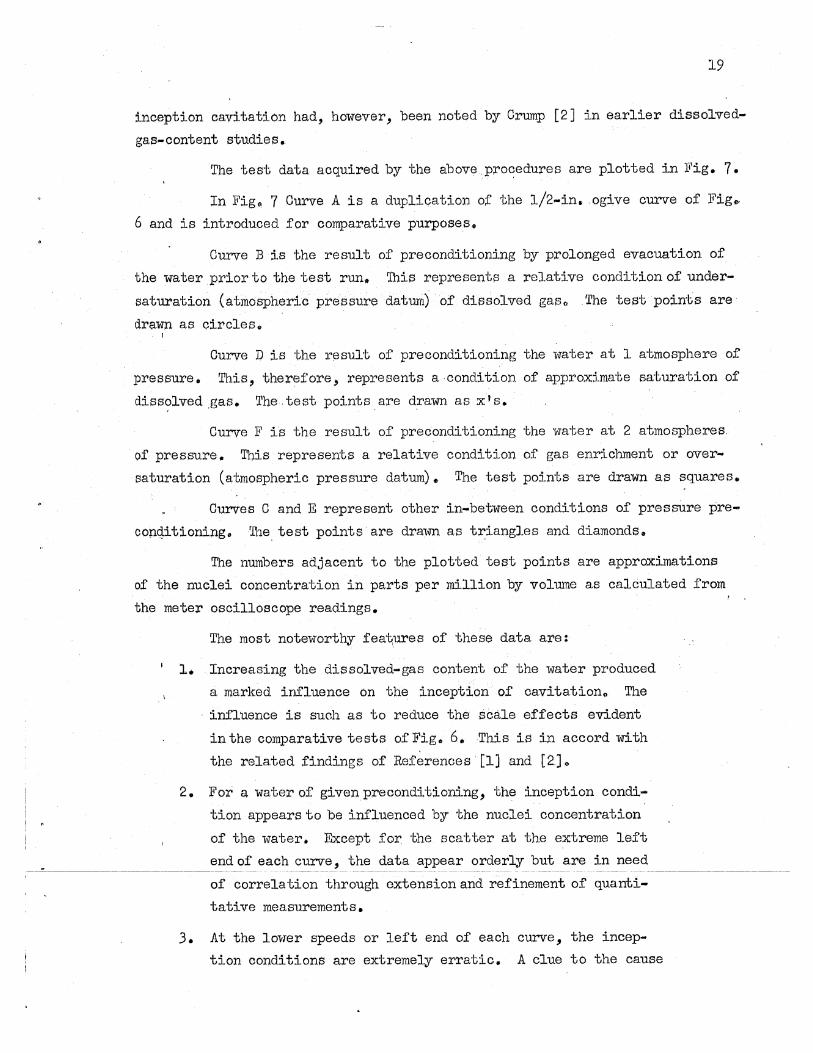
inception cavitation had, however, been noted by Crump [2J in earlier dissolved
gas~content studies.
The test data acquired by -the above,pro~edures are plotted in li'ig. 7.
In Fig.,. 7 Curve A is a duplication of the 1/2.-in. ,ogive curve of Fig .. ,
6 and is introduced for comparative purposes,.
Curve Bis the result of preconditioning by prolonged evacuation of
the water ,prior to the test run. '!his represents a relative condition of under
saturation (atmospheric pressuredaturll) of dissolved gas.,., The test points are
drawn as circles.
Curve D is the result of preconditioning the water at 1 atmosphere of
pressure. This, therefore, represents a condition of approximate sa:turation of
diss?lved ,gas. The test points, are d,rawn as XIS.
Curve F is the result of preconditioning the water at 2 atmospheres,
of pressure. This represents a relative condition of gas enricltment or over
saturation (atmospheric pressure datum). The test points are drawn as squares.
Curves 0 and E represent other in-between conditions of pressUre pre
copqitioning. lJbe test points' are dra1m as tJ\iangles and diamonds.
The numbers adjacent to the plotted test points are approximations
of the nuclei concentration in parts per million by volume as calculated from
the meter oscilloscope readings.
The most noteworthy fea~ures of these data are:
1. Increasing the dissolved-gas content of the water produced
a marked influence on the inception ·of cavitation.. The
. influence is such as to reduce the SCene effects evident
in the comparative tests of' Fig. 6. This is in accord with
the related f'indings of' References [lJ and [2].
2. For a water of' given preconditioning, the inception condi
tion appears to be influenced by the nuclei concentration
of' the water. Except for. the scatter at the extreme lef't
end of each curve, the data appear orderly but are in need --'''----~ ------ ._--- ------~~----~--------------~-----~ - -------- --------
of correlation through extension and refinement of' quant.i-
tative measurements.
3. At the lov1er speeds or left end of each curve, the incep
tion conditions are extremely erratic. A clue to the cause

20
of this erratic behavio~ is tobe found in the sudden shift
to a very high nuclei concentration as indicated by the meas-. . ,
ured values. The mechanics of this transition are in need
of further clarification but are presumedt6 be related to
critical nuclei sizing in accord with Fig. 1.
4. The basie natureo! the cavity form varies at'inception.
In the low dissolved-ga$ region represented by Curves B
and C, the cavity was nearly alwars a small steady-stabe
ca;vity :of Abropt··a:ppea.~~c;e.·si1<idisa.ppearMces · For the . . .' .. "." '.. .
higher dissolved-gas' curves--D-, E, and F .. ';'the cavity was
a transient-bubble El'trE/ak" Steady-state cavities were rare
in the high dissolved-ga2, region" but in the lo~-gas region
a streak"'\bubble . incepti.::m coUld frequently be noted prior
to the appearance of 'ih~ steady':"state cavity. T~e data.
ent~esinFigo 7 ,which are connected by a vertical dotted
line, represent these dual inceptions.
5.. The influence of the nuclei concentration in reduci;ng prev
iously not-edseale e£fects appears to be most powerful at
low 'test,' speeds and of diminishing influence at high speedsli)
, This appearance is partially the result of employing a cav
itation index falsely based on the assumption that vapor
pressUre en.sts in the cavity and is partially due to the
complex way in whichmeancirc1lit pressure varies with veloc~
i ty in a tunnel circm t.
6. Figure 7 clearly shows tha.t a separator type of tunnel 'Will
permit an effective variation 6f nuclei-concentration con
ditions by .suitable regulation of the relation between t~e
preconditioning saturation pressure and the actual testing
pressure. However, the figure does not directly indicate
that the nuc1ei are sufficiently stable to pei;nd t tunnel
tests of a reasonable duration.. In this respect" it is of
considerable significance that the numerous data points for
CurveB. span a test period of 150 minut.es and the data of
CurveEspan a period of 75 minutes" The data points were
mixed'in sequenoe during these periods" It woUld appear
that the controiprocedure provide a adequate stability for
the usual type of tunne1,test~

7 ~ Earlier studies of dissolved.-gas content [llJ conducted in
the 6-in. St. Anthony Falls tunnel prior to the separator
modification established 'chat the dissolved-gas content
could be reduced to a minimum of 'about 10 parts per mil
lion 1:v weight and ~increased to a maximum of about 28 ppm.
These values assume signific<'/.nce H' it is recognized that
the saturation val ue at atmospheric pressure is approxi
mately 25 ppm by weight or about 20,000 ppm by volume" If'
theSe earlier values are compared with, the :range from 10
to about 200 ppm by volume of nuclei' concentration (as
measured in the current 'tests),' it is apparent that the
nuclei concentration is a relati'V'elyminute quantity. Theep·,
values may also shed light as to w~y the CIT-ORt inception
tests [10], the results O.r which are summarized in Figo 6, failed to show significant changes with variation of gas
content.. The gas content in the CIT .. ORJ~ tests was varied
from a.bout 7 to 12 ppm by weight or 1/ in other words.9 the
highest va.lue repi'esented'Only abont50 per cent of' nor
mal saturation. Failure to show gas-content effect's in
the CIT .. ORL tests may also be attributed to the high pre
conditioning pressures to which ?oth tunnels subjected ihe
water" '.A.nalysis [7] of t/he combined dyrtamic and static
pressure in the CIT tunnel indicates that the average cir
cuit pressure varies from about. 3 ,to? atmospheres depend
ing on speed. The ORL tunnel, being without a reabsorber,
did not possess Circuit pressures as high as the CIT tun
nel but was stated [10 J to have l)een manip'Lllated to subject
the water to 3 atmospheres of pressux'e for 10 minu:tes prior
to each run" Since Strasberg [5] f01IDd that even 1 atmos
phere of preconditioning pressure pl~oduced substantial
changes in the critical cavitat,ion ... inception pressure, it
seems qui te reasonable that the ga.s-conten·c effects
appeared negligible for the limited OIT-ORL tests. The com-
21
:,-------------------------- binedeffect of-alm.! dissolved-gas cont.ent.andhigh __ pre~ ___________________ _
conditioning pr..essure probably also accounts for the fact
that Curve A of Fig. 7 is lower than Curve B,

22
V!r. CONCLtISIONS
The faCilities and. procedures' described herein have been subjected
only to limited tests and. the l"Elsultingdata are accordingly fragmentary.. It
is intended that these studies be extended with til view toward confirmation,
but ,ending such' additional studies, the· following tentative conclusions appear
to be in order :
1. A conventional water i'tUlile1 can be provided 1d th a. gas-bubble
separator system; which nlipel'ndt>the t_1 to be effec ...
tively operated'W1th' a water of controlled high nuclei con":
centration ..
2.. : The nucieiconcentrat;.tpn; of:;,a. 'tWater :. (!,or;,comnmtrat:tb':tur~:
above 0.1 ppm 'by vol't1lJl$) can be measured with great . sensi ...
·t1vi~ by measuring the ratio of the acoustic velocity of
the test water to the acoustic velocity of water without
nuclei ..
3.. Ce:v:l tation ... inception tests using water Wi th a high concen ...
tration (of 1l,tl~· nuclei· are significantly different from tests
.~sing low concentrations. Scale effects previously noted
"in ~ther tunnel studies were found to bek substantially
decreased in the cUrrent 'tests 'which used high nuclei. con
centrations.
4. Ca.Vitation inception in the form of steady-state cavities
of abrupt appearance and disappearance tends to occur in
water having a relatively low 'nuclei concentration. . . .:: ..•. ". , .'" '..' '. . " -,- '. .
, 5.. Cavitation lIiception in the form of transient bubbles tends
:-to" occur in water having a relatively high nuclei concen-'
tration.· 6.' Hysteresis effects associated 'With the appearance and dis
appearance of inception cavitation resUlted from the use
of waters of low nuclei concentration and were not appar~ ant in waters of high nuclei 6oncentration.
7. The portion of the gas content of a water which is in the
form of nuclei is probab~ much more influential in cavi':'
tation~:i.noeption processes than the portion in the dissolved

i '
£'orm, despite the fact that the mass of the former is prob
ably less than 0.5 per cent of the masS of the latter ..
8. The maintenance of a high nuclei concentration in the tun ...
nel water requiredi':mairitenance,' !,of" ;& 'lligli· d.±esolvltd.4gas
content.
9. The control of water-tunnel cavitation inoeption by pre c on
ditioning the nuclei concentration of the water appears
definitely to improve certain'prev iously noted scale
effeots. The improvement was greatest for the low speeds
cornmon to propelier tunnels. For body studies in a high-, ,
speed stream, the control appears less effective.. The
loss in effectiveness is presumed to be associated with
the high circUit pressures that inherently attend high '\est-.
section speed. It is possible that USe of even higher dissolved~gas contents might also ~rove the effectiveness
at high speeds.
10. It would appear that gas-content instrumentation yielding
,data reg~ding the size of nuclei might better character
ize cavitation-inception conditions than instrume~tation yielding either dissolved- or free-gas volume. The gas
Volumes may eventually prove to be significant faotors in
studies of extensive cavitation or perfo:rmance breakdown
but are beiieveq to be of lesser importance than.nucleu.s
, size ill inception studie s •
23

24
[1]
[2]
~... :;
Edstrand, Hans" The 'Effe9!...Of' Air gorrtent of. 'lNa,ter on the ,c!vitation ?~int and VEon 'the Ghara.cteristics~f. ShiEs Propellers~. ;'Swedish State. Shipbuilding EXPerimental Tank Pub1ica.tion No.6,
"'Gtsteborg, 1946 .. '50 pages~ , : , ... ,:; . .
Crump, - . , " ." . .
s~ ,]f-. Determina'liion ,of Critica.l Pr~ssures for the Inceition of 'CavJ..taIr"on iii Fl'6Sn 'and Sea. Ulfater as: Influenced b~ fir Conten'£
·'".,~fti,hew;lE!,~~De;rld 'Tailor> !(oclelBasin ',Report~75, October .' !9Ii~ •. 37, pages.
[3] Iyengar, K. .. S."al'l<i Richardson; Eo G. 1P.-el1.tita ofCay:t,tation,Nuel!3i.Me,",'. chan.i~a:L, ~ngine,e:ring Re,aee.reh I,abora-tory Fluids Report No .. 57 ~
'. August 2957.. 24 pages 0 , '
[4]
[5]
[6]
[7]
[8]
[9]
[10]
Daily ,,--:J .. )J~,a~d Johnson." V l' E.~· Jr" Ii Turbulence and Boundary .LaYer Effects .. , . on Cavitation Incep'(;i~on From Gas Nu.c1ei 9 u 'fi'ansactions of the
,4.meric.ru: .. §.,9~ie·l:.l;,(')fMechapJ.cal. Enginee:rs, Novein'ber1956. 19 pages"
Strasberg 11M. The Influence of Ai2:.-F:i.Y..2..4...!lH~lei .. ~n Cavi ta:tiort ; Inception .. ....David'l'aylo?=' MoWei Basin Rapor-I:. !"018" May i957 ~ 25,pages ..
Knapp, R.T." Cavi t~tlon and '111-101e:1. American Society of Mecha¢.cal Engi-.' 'rieerirPaPo£'NO:~:;a()";195'1" 10 pages, : . .'
Brown, "F~. Be .~.r ResO~ij:iOl~~~?unnef.f!", Californ;ta Institute of Technology', Hydrodyn.rur.t:i.cs Laboratories Report' No.N .. 62, March 1949..22, p.iages.
Rouse ;-R:" and HassaIl,M" M!, . iIOavi·cation ... Jj'ree fuetsand 'ContZ;aetions. tt
. <'., !echatd.ca1Eng:i.neer:i~9' pp~213;.,216~· March 1949.::·;
Eisenberg, p" "A Critical Ravia,;; of Re<!ent Progress in Cav1tt9.tion Re ... I . search" If Cavi tatiO~l in ~!d~~.t.amics a Proceedings of a s~ ..
12osi~. :N'itloiii! PE:ysica tiilOratory, Sep'€ember 1955.. i pages.
[11J Olson, R" No 2!!.itation Testing ~.~l Wat,e:t:, Tuxme1!!o University of Minnesota, St" Anl:.hony P'al1s r:rydraulic I..aboratory Project Report No" 42, December 19540 49 pages,.

• °
I 4
OF I G tr RE S - ..... -..' ............ ~ (lOthrough7)


\
"
.... Q) ..c
2.4
2.2
2.0
1.8
1.6
:s: 1.4
b ..-~ 1.2
IJ..
.E
fl~ 1.0
-c c .8 Q)
:::r: ~ l1l .S If)
~ a..
>-- ~-
~- -
>--- -
I- - -
~ - -
~ M
If) -I-
~ II :w; -
" - -
I- -
-c Q) If)
o 0..
4f-- -
E '': 21--
, , ! I '
-- -
---
- --
-1- --
- - - ~ 0 - , )C
In I- -- ,.., 0'
, II
':w:: ---~
" - - ,..--:-
-~ ~-I- - ...:..\--
I
,
Q) 0.. :J
CI)
\
\ \ I '
0>--- l~ -
.:..-- ... 2
\ I~ V-
I /y 4;\ [7~ e
J
T= 68 F
-
--
i
,
"
.. -- -- 5------- 10--- 15- ---' 10-- 25----30--- - 56 --- 40 ---- 45 ---1i b ----- ~-----~-- 0
Bubble Diameter D Inches x 103
Fig. I - RelCltion Between Bubble Size Clnd Superimposed Pressure CIS Influenced by Gas Content of the Bubble (From Reference [4])
27

28
O.20"Gdlv(]hi:Zed l S~~
=1'0
______ ._J I\\..,...-----#--A Row of 1 Air
Drainage Holes of t." Oia. Beginning ~" frOin Leadin9 Edge and Spaced at 2il Intervals
Fig. 2 - Configuration of Gas-5eparotor Tube Employed in Tunnel Tests
Fig. 3 - General Atrangement of Separator Tubes in Tunnel Cross Section as Viewed From Upstream

29
__ -L-____ . ____ _

30
rl· 8"'-'--~----'--'-_--------I
Vane Detail
-UI I£, '0 I:;) I~ \ fT\ I~ Ig.
~.I .;z, \ 1 ,(Jl
I~ 1('1 I?,. 1
2b" ---....::t.. " ',-.......
Elbow Assembly
Fig. 5 - Arrangement of th~Jwo-Dimensional Combined Turning Vane and Flow Diffuser '

·8 I
::3 0 -0' (j)-::3
;:; .6 0 < -0 -0 ::3
:5 0-CD
I x OJ 0 .4 (/I CD 0-
0 ::3
< 0 '0 0 .... "0 .... CD
.2 (/I (/I
c:: .... (\)
a
Ih
I \ 8~
.~ I
20 40 60
Velocity in fps
Hemisphere !cPminl = _74
Ogive \cPminl = -404
4" 01
~ . 1/2 -
80 100
Fig. 6 - Relation Between Incipient Cavitation Index and Test-Section Velocity for Various Sizes of Hemisphere and 1.5-Caliber Ogive Head Forms (From Reference [10])
120
\.oJ I-'

32
.34
.32
~.30 ::I en en CIJ ~
Q..
5.28 c.. ~ c: o
"C .26 CIJ en o m )(
~ .24 c:
c: o
:;::: o . :t:: .22 > o
.U .0-c: CIJ ·i5...20 '0 c:
. 18
.16
.14 20
X
g
.&
01 188
, I\.
190 95' 2b6
¢ .
O~ 184~ 197 _
H9 ~re~ X¢ 188 . ~Q
°Ul <1
29~~ '0 ~ Y 36 ~ " 0 r-----:---x-
I ~ I-- ,
I I I T X , • ~9
~ , • V
3 I .& 30 - ,..
/~~ .& I I I 1,..."""'-
I~ , , . ~/ ..,....-I ~~V21 /
/"
I I ",G /" I ,
.L ~\:l} J6 I -<.eJ.''''/ I - \.-0 :'O~ ,
C,-<' I
I @~ ~/ . 1700 . ./
Vjj,/
Note: Numbers Adjacent to Data Points .& Represent Free-Gas Content in ppm
of Volume Based on Measurements in the Contraction Chamber
0 Filled Symbols Represent Steady-I State Cavities
25 30 35 40 45 50 55
Test-Section Velocity in fps
Fig. 7 - Relation Between IncipIent CavitatIon Index and Test-Section Velocity for an O.S-In.-Dlameter, 1.S-Gallber Oglve Head Form as Influenced by the Gas Content of the Water
;,.-
-
60

i P PEN D! j( A ------- ....... ""'*
1 Ii
I
i 1
. --------.------------~--- .~----------------~----- - --------- ------~-~--.-----------

•

A SONIC METHOD OF MEASURING - ----- ------ ---------THE ~Q!Q!!!~!!lQ! Q!
UNDISSOLVED GAS NUOLEI IN WATER ---~------- --~~~~ --~-~
I. INTRODUCTION
Various sonic methods mightbe used to detect undissolved gas nuclei
in water. The reverberation decay rate at ultrasonic frequencies and the
intensity of ultrasonic sound necessary to initiate visible cavitation were both used to detect gas-bubble nuclei by Strasberg [A-I]*o Wood [A-2] indi
cates the effect of gas bubbles on the ve100i ty of sound in gas-water mixtures, and this suggested a third method wherein the nuclei concentration itself
could be determined.
The third method was developed to measure low concentrations of
gas nuclei in water 0 Preliminary measurements were initially made in open
water at rest and were followed lid th tests in moving water in a 6-10. water tunnel. This appendix describes this work.
110 THEORY
The acoustic velocity 0 in ~ homogeneous medium is given in
terms of its elasticity E and its density p as
c =./E/p (1)
Let subscripts m, w, and a refer to mean property· valu.es, those for water, and those for gas, respeotively~ let x be the proportion of gas by volume; then the mean density is
The mean elastic modulus can be calculated by treating 'its reciprocaJ., the
com pre s sibili ty, in a like manner I> Thus,
* Numbers in prackets with prefix A refer to the List of References on p. 44.

1 I-x ~=~+-----
E ,~ w
and
EE a w, ~=------
, , xE + (1 - x) E 'w - a ",'.
. ~',
J ..!.J,: .. .:. . .(,
at a pr~~sUre ~f 'l.latmosPheres~~ a 'teinperat~e of BOF rep~rted Dy ~aiber-~man [A-)] indicates that at the 1m(' gas concentrations to be e.xpeeted1.n ,tunnel
operai1ons(belGwi per 'cent by- v0l:-lll1le) ~ , the phemoDlenon is isothermal. rather
thanadi'abat1e":' th~ elastic i40du.l~s .for the gas then- becomes equaltotl1e
absolute presSUre' :,'" , a
, The ratio of sound velae! ty- ill, a. l1o~sonant gas-water mixture to that ill pure water becomes
(2)
whid! is alwaysless than lmity- and de~ends primari1,:'Q:n the redu.ction in the
ela,li$~i~ .odulus'"'t l~fgas.C?o~eentra.tioub ,(The mixture is mo1'6 elast1e or
more _:c~mpressil?l,e thaJ?, ,J>tl:X'e ,wa~r!t-J. ~ For gas eoneentrat1o~ les,s than-10 ... 3, this velocity- ratio becomes
,--'" _I _(~_a~-X_, ""Pa- ~ [-!;~~~ .. .. ~.
(3)
~~'. ' . ..., ..
because xPa < < (1 - x) Pw and (1 - x) pw• ,Plio'
'~-;:.: ':; ''l'~svlalolQity-''ratio is plotted .for a-r~ge, of gas concen'trations
from 10-7 to 10-2 at a pressure of 15,,94 psis. and a temperature of 8e Fin' "

1
I I
: I
~
i ,
1
t !
.,
Fig. A-l. The confirming measured values reported in Reference [A-3) are
indicated. The lesser agreement between measured and calculated values at
the lower gas concentrations is attributed to the difficulty in making direct
measurements of the extremely small gas volume contained in a. given volume of
Ii mixture.
A. 'Effect of Pressure
The acoustic velocity in a nonresonrunt gas-water mixture is reduced
either by an increase in gas concentration (at the law values of interest) or
by a reduct:tonin pressure of the mixture o The effect of reduced pressures on
amplifying the reduction of acoustic veloCity, as shown in Fig. A-2, is espee~'
iaiiy advantageous for meas'urements in water tunnels where cavttation testing
is usua.lly done at subatmospheric pressures.
Fo~ example" if' there are 10-5 pa1;'ts of entrained gas by volume in
a. wa.ter-tunnel test section at a'pressure nearly atmospheric (32-ft pressure
head), the velocity ratio is 0.90, whereas this Same gas concentration at an
absolute pressure head of 2 ft. results in a velocity ratio of 0.46. Very sma.ll
concentrations of gas nuclei are therefore'more easily detected and measured
as the lower pressures more commonly associated with cavitation testing in
water tmineis are approached.
B. Effect of Ternpera~ure
Temperature affects the elastic modulus of water slightly. In the
rang~ from 60' F to 100 F» the Variation is abo~t 2.9 per cent, from the me~ value at 1'5 F, 'I:.he temperature at which Fig. A-2 applies. Calcula.tions indi
cate that for te!DPerature variations in this 60 F to 100 F range, the velocity
ratio given by Eq. (3) will differ from that plotted in Fig. A-2 by less than
1.5 per cent at gas concentrations less than 10-4, and by less than 1 per ~nt for gas concentrations less than 10-5 • ' These statements are valid :for pres
sures aboy9 0 0 2 atmospheres.
C.. Measuring Frequencies
The preceding theory is v&1id only if the frequency of the sound trans
-~,--~-- --- mission is nonresonant for the gas bubbles involved.··· In order that -these
gas-bubble nuclei be nonresonant, the impressed frequencies should be no
greater than one half the resonant frequency of the bubbles [A-3J. " ;t,'1,:--,

38
(Frequencies well above resonance may also be useful but were not investj.gated.)
These resonant frequencies f are approximated by [A-h] r
where D is the diameter of the gas nuclei, k' is the specific heat ratio for
the gas (1.4 for air), p is the average absolute pressure" and P.~iT is the
wa.ter'density--all inconsistent 'Q!lits.
The interrelationships between the pressure, size of nuclei, and
resonant frequency~eshown inFig. A-3. Superimposed on this family of curves
is another group relating the us-q,al ca:vitation n:utllber (based, in this instance,
on a vapor-pressure head of 0.9ft of water) with the test-section velocity
and. pressure for a water tunneL From this g:raph can be determined the non
resonant frequency at which .the Moustic velocity in a gas-water mixture may
be measured. For example, if tests at hO ips at a c.!flvitation number of 0.5
are to be run, the test-section pressure head is 13.2 ft. If the largest I
nuclei present are 0,,008 inches in diameter, their resonant frecpencies are
23.1~ kcps (interpolation between frequency curves is linear), and acoustic
measurements should be made at, a frequency of 11. 7 kGPs or less in order that
resonance be avoidedo Equation (3) "'rill then apply.
III. BUBBLE SIZES OF INTEREST
For the proper selection of'impressed frequency for a nuclei
concen'~ration instrUltlEmt j it is necessary to 1n10W 'the maximum size of nuclei
to be expected in the test section of the cavi·tation tunnel.
Currently there is a scarcity of information regarding the size of
nuclei essential to the promotion of cavitation and what information is avail
.9.ble is largely conjecturaL In addition, there is a considerable question as
to the actual size that can be maintained in the tunnel flow under practical
operating conditions and pressure variations. The selection of a limiting
frequency of transmission is therefore complex.
Available information [A-I and ,A";5] and laboratory experience with
gas-nuclei-and-w'ater inixtures where the nuclei were below 0,,006 to 0.008 inches
in diameter indicates (further conject'UX'e) that it is unlikely that nuclei or

bubbles larger than 0 0 010 inches in diameter would (or should) be present in
the test section of a ~ater tunnel. If test-section velocities are 30 fps or
more, Fig. A~3 indicates that resonant frequend.es will rarely be below 15 kcps. Thus a 705-kcps measuring frequency 1iV8.S believed to be satisfactory.
IV. METHOD OF HEAinJREMENT
The acoustic velocity in irJa:tor or in a nuclei .. end-water mixture 'Was
determ:l.ned by' measuring the transit time of sound pulses between a transducer
and a pickUp. Actually, the transit time in a mixture was compared with that
in pure water to give the velocity ratio cf Eq. (3). nle gas-nuclei concen
tration WaS then obtained fr.om Fig. 11.-2 •
.A. Transducers
'Two pure-nickel-core magnetostriction transducers were used, each
having a ~atura1 frequency in the audio range (15 and 7.5 kcps, respectivelY).
This type of transducer was chosen 'because of its excellent coupling qualities
both :in preliminary tests in direct contact with water and in itfl adaptability
to water-tunnel USe. The transducers were designed from data given in Reference
[A-6J and were made at the Laboratory because they were not available commer
cially. Both were driven at a. repetitive rate' variable from about 6 to 30
,pulses per aecond by a circuit shown in Fig~ 11.-4.
B. Pickups
Pickups included a Br'Ush 1{easurement Hydrophone, Model' BM-lOlA" with
a. frequency range of 0 01 to 100 leops and a barium t,i tanate ceramic crystal. . I
This crystal was lilt' lno long and 1 inch in diameter with a natural frequency .
of about SOO kcps.
c. Oscilloscope and Oscillogram Interpretation
An oscilloscope with a trigger sweep is required. In these tests a
Dumont 208 oscilloscope 'with an added trigger sweep was used for transit-time
measurements.
________ ,~______ For direct measurements of the velocity ratio given in Eqo (3), the length of the oscilloscope traces (Figso-A':S alla:-A':6)~- -L '.' .. and -:L~-~ere-----
o x measured, since they were direct indications of transit time of a sDund wave
between transducer and p:i..ckup. The IIknee lt at Lo became more rounded (arid

40
less easily located wl:th precision) as the concentration of nuclei increased.
The sinusoidal poriion of the oscillogram did not expand but mere1yshiftedin
position with a change in transit time, and therefore L.' - L I was measured x 0
directly (with more precis;i.on than ~..:: Lo) md was used tb determine the
increase in Lo to ~o Then, if T refers to transit time, fora fixed
path length from transducer·to pickup,
L + (t ' ... L I) o x 0
For velo~ity ratios beiow 0.9, this velocity ratiO could be deter
mined with a. maximum error of about ZO.Ol •
. For velocity ratios near unity, a delay circuit was set up, such
that the increase in transit time of a. sound pulse between transducer and
pickupw8.s indicated directly on the oscilloscopev This circuit consisted of
a ~A .. 8886 plug':in unit (E1ectronic Engineering Company of Los Angeles) as
indicated in Figo A-h. Typical. oscillograms are shown in Fig. 11.-7.
For examples if the first circuit ('Wi. thout pulse del~) were used,
and the oscillograph trace increased 11i8 units (L ' ... L t) from an initial ·x 0
iength of 30 units (Lo) as a result of adding a certain concentration oinucls,i,
. then
c x 30 .-. ------ == 0.943
30 + 1..8
and the nuclei concentration could. be obtained from Fig" A-2 for the appropriate
ambient pressure. The sensitivity in this instance is rgther poor.
If the delay circuit were used, the sensitivity and accuracy would
be much better 0 Calibration in this instance is readily illustrated if the
transducer and pickup are innnersed in water free of nuclei. An increase in
spacing between transducer and pickup increases the transit time of a sound
pulse between themju.st as would the presence of nuclei. For exmnple, sup
pose the spacing between transducer and pickup were increased froll! 6.00 to
6.60 in., which results in a ~engthening of the oscillograph trace of 20 units.
Then,if the transducer-pickup spacing is set at 6.00 in. and the addition of

nuclei lengthens the oscillograph trace 12 units (Lx. t ~ Lo i of Fig. A-7) , the
ratio of sound velocity in the m.ixture to that. i11 pure wat.er becomes
c x. 1 - ... ----.-.---- ., Oo9h3
The increase in sensi ti vUy with the delay circuit is more than six
told in this example.
V. PREl,IMINARY MEASU:REJVIENTS IN OPEN WATER AT nEST
The instrumentation 1I\JaS c.hecked out and the sensitivity of the method
was initially conUrmed by suspending the transdueer and the Brush hydrophone
in water contained in a long glass-sided open 'I:,ank 6 ino wide and about 12 ino
deep. Small and well-dispersed nuclei viere supplied to ·the tank by rec:i.rculat
ing rome of the water through a pump "Wi:l:,h a 3/h-il1o gate valv!3 in the discharge
line adjusted for a 4o~ to 50··psig discharge pressure. Nuclei less than 0 0 008
inches in diameter resulting from (it is believed) valve cavitation were dis~
parsed throughout the water in the open tank.
When the' nuclei· were being supplied a.t a constant. ra.te Jl velocity
ratios (Eg. 3) as low as 0.5 were recorded. (This same value was also obtained
in the water-tunnel tests.)
A number of measurements were made ijO check the, response of the
measuring system in quasi-steady states of gas-'vvater mixtures in an open tank"
Nuclei were supplied to the water bet,ween and surrounding the transducer and
pickup, and when this supply was shut off» it. was expe(;-l;,'ed that these nuclei
would disappear by gravitating upwards or by dissoiving :Ln:to the water at a
continuous (though not constarrl:,) rate 0 'fheir p:e8senee 'Has measured by compar
ing the acoustic velocity at "lTario1.:s instants wi:th the acoustic velocity when
the nuclei were considered to have disappeared. Typical curves are shown in
Fig. A~8.
The sensitivity of the measuring system'lrms checked with the smooth
end of. the transducer core and the bariuJll tit~natc ceramic CI"Jstal pickup
placed in direct contact with the opposite outer surfaces of the glass walls
of the tank. Coupling was improved by adding a drop of castor oil to the
glass surfaces. Nuclei were gener8ted in t.he water as before, and the

amplitude ~d lengthening of the osctlloscope trace indicated excellent sensi
tivit~it This was considered a significant point. It indicated that a magneto
striction transducer and a simple ceramic pickup could be mounted in contact
With the external surf'aces of a water-tunnel test Election. This would preclude
any interference with the internal boundaries of the tunnel and would pe1'nlit
measurements ·to be made with no disturbance to the flow.
VI.. ADAPTATION TO WATER-TUNNEL MEASUREMENTS
To confirm the above indications, the transducer and pickup were
mounted externally near the begi~ing of aalosed-jet test seotion of' the
6-in .. water tunnel at the Laboratory.. Two diametrically opposite flat swfaces '. ..
were milled in this acrylic resin plastic piece, and the· transducer and pickup
were mpunted in good contact with these flat surfaces, castor oil ~eing used
.at the interface to improve coupling.
Initial concern regarding the effect· of tunnel vibration was disPf,llled
when the os cillo grams showed good wave form. At only one tunnel speed did the
wave form become unstable, and this was due to the vibration of a nearby mount-·
ing s~rut.
The system showed good response to the addition of nuclei into the
tunnel water, and further tests are described in the main body of'this report.
Consideration should be given to possible interference from sound
pulses traveling cireumi'erentially ""hrougb'the tunnel walls to the pickup in
addition to ,a diametrical path. In the mounting deSCribed, this occurred at
a velOCity ratio (Eq. 3) of about 0.5 to 0 .. 6 •
. VII. SUMMARY
Although the nuclei-concentration meter described herein has not been
tested under a ;r-ange of conditions which clearly establishes its. role in water
tunnel prog:rams~ it is believ~d that some significant conclusions may be drawnr
1.. The method of measuring the velocity of sound in a mixture
of gas nuclei and water described herein was demonstrated
both in open water at rest and in a water tunnel with flow
:i,ng water and with a flowing water-nuclei mixture and proved
to be a practical and accurate method of determining the
concentration of minute gas nuclei, in water.

i I •
1
2. The somewhat unconventional use of' a magnetostriction trans
ducer. in the audio range permits the installation of a
workable nUClei-concentration meter on a wa-lier tunnel with
E2. interference with the flow through the tunnelo
3. The principle of operation of' this meter penni ts esse~
tially instantaneous indications of the nuclei concentra
tion.
4. It is relieved that the method is very promising, and add:i.':'
tional instrument development work should be pursued.
Such development will contribute materially to studies of
theinf'luence of nuclei concentration on cavitation and
to eventual control in a water tunnel •
. ()
4.3.:,

44
LA"'l] , Strasberg, M. IIUndis~6lved Air Cavities as Cavitation Nuclei-It Symposium on Cavitation in Hydro9Y?amics. Teddington, England: National Physical Laboratory, 1955.
[A-2] Wood,.1. B. A Textbook of Sound. New York: Macmillan, 1930. pp. 327-328.
[A ... 3] Silberman, E. nSound Velooity and Attenuation in Bubbly Mixtures
[A-4)
[A-5]
. ][easured in Standing 'fftTave Tube,lI The Journal of the Acoustical Society of America o August 1957.
Anonymous 0 The Physics of Sound in the Sea. of Division 6, NDRC, Vol. 8. 1946.
Summary, Technical Report
Daily!! J. W., and Johns on, V. E", Jr 0 II Turbulence and Boundary Layer Kffects on Cavitation Inception from. Gas NucleLIITransactions of the American Society of Eachanical En~ineers. November 19~b. I~ pages. . . .
[A-6] Anonymous. Design of Nickel Magnetostriction Transducers. The Interm tiona! Nickel Co., Inc.

'v' ..
",
FIGURES -----_ ......... -(A-lthrough A-8)
1 I ' 1
,
L • ,


------- _._--- ---~---
I./~ r---r-""-"""T"TTTl'----'---'" 11-'lrrT I lin-III -"--'-11""'-11""'-I I ITT 111-----'--1---r"1-'-1 1"'1 --rrr-----,--,-,,--yTTTl
Pressure 39.6 ft woter (2296 psfa) Temperature eo F
5 ~ 1.0 1-++~~r""'fTTl~ -rrr-T-ITTTTI. ~Il ~I. .TTlIJITHtI t-H1t1ttt1 ~~ ,~ CalClllated Curve 'g ~ O.B 1-___l_+-+++-H+l--+-H-H+l-H----+~~-HA-H--h------,.--y-,..,.-rTTT..---+----l-I-H++t1
~~ ·K '"C .5 § 'E 0,6 1-___l_+-+++-H+l--+-I-+H+l-H----+--+-I-t++-l'\:I-,,---i-t-+-++t+++--t-t--+-H-H1-H O,c (/)1-oQ , o 0.4 I--_+_++++-I-ttt--~I-+H+ttt---t--+-I-t-H+tt--+""d_++-I-ttt"l--t-_+_H-t-ttti
~~ ~~~ ~ 0.2 t-----+--+-I-I~--I---H-I-+H-I-_I__+_+_H Ijlj"'"T I Vln~ ~ ~ O~~~~~--~~~~~~~~~~~~~~~~~~
10-7 10-1:? IO~5 10-4 ICf3 lo-g
Ports of EntrainedoGas Per Unrt''iJolume of Water
FIg. A .. , ... Reductl91'\ In ACQu.tlc: Velocity In GCI$-Water MlxtlJre~
47~

48
1.0
r:::::: r-:: r- to- .... R ~ i"-.... r... "" ~
j-..... t'o-J'.. r-... r--.. t--,...
'" t\.. "
~ --...;;
f\ 1"- 1\ 1\ \ Temperature 75 F
\ r\ i\
\ 1\ 1\ \ \
1\ \ 1\ 1\ ~
\ \ ,
~ ~ ~
1\ 1\ ~ ,
Absolute Pressure Head 2\4 16 ~2 in Feet of. wat~ 8 ,
\' \ '\ 1\ 1\ 1\ 1\ \
\ J\ \ \ 1\ 1\ 1\
"' ~ 1\ ,
1\ 1\
f\ '" f\ I\. 1\ ~
'" '\ f', 1'"
~ ~ "-'" r-.... i'
....... "
...... ..... 1'-0" ",
0.9
~
Q) 0.8 -~
Q) ... ::::l
a.. 0.7 c:
-0 .£: t-o 0.6
0+-
Q) ~
::::l 0+-X
~ 0.5
c:
>. -'0 0.4 0
~ -0 I:: ::::l 0.3 0 (f) -0
0 :;: 0.2 0 0::
0.1
- " - /' - -fO 6 10 5 10 4
Parts of Entrained Gas Per Unit Volume of Water
Fig. A-2 - Effect of Pressure on the Reduction in Acoustic Velocity in Gas-Water Mixtures

... Q) ..-0
3= -0
..-Q)
~ c:
"'0 0 Q)
I
Q) .... ::l I/) I/) Q) .... a.. Q) -::l 0 I/) Ll <[
35.--------.--------.--------.--------.--------.
30
25
20
15
10
5
0.005 .0.010 0.015 0.020 0.025
Bubble Diameter in Inches
o 0.1 0.2 0.3 0.4 0.5 0.6 0.7 0:8 0.9 1.0 1.1 1.2
Cavitation Number
Fig. A-3 - Resonant Bubble Size at Vatlous Frequencies and WaterTunnel Test-Section Conditions for Various Cavitation Numbers
49
\

So
JL --to ~ II - - Dela.yed D.elay.t 100051'1 Sync Circul I· 1 Pulse
1.00951' _.:..p. --.-: -__ - __ --.l ~- - - Sync.
r I . Pulse
: O·~lf 1000 ~ .1>
Transducer
Filaments
., P Ise Ci rcuit Fig, A-4 - u

i 1
I i I
Portion Shown in Fig. A-7 i
Portion ShownJ in Fig.A-6
n
Fig A-5 - Oscillogram of Wave Form
--- --L~--~~ Pure Water I
~L.-----I L 11--__ L~ -K:31Gas-water I: _ Mixture ~---Lx---~
-.-------,;;"-Pure Water
~-Lo.;..J_· -L~ ~1L ~ Gas-Water
___ --.j~ Mixture Lx
Fig. A-6- Oscillograph Traces for Di recf Measurement of Transit Time of Acoustic Wave'
o
·Fig. A-7 - Oscillograph Traces with Delay Circuit .'
5
i'O
20 ._ g Q) .-
~ 0.8 l--ArI-."+--I--I-+-+--1-+---'Y---+--+-~ u= 30 ;:,:::i! z ... I Q)
0::
40 .= 0->-- ".--7.5 kcps transducer I~ 0.7 1----.-11---1-+-+-+--1-+--1---+--+--1-4- 50 «1/1
-ct: Q) c
~ ---cr- 15 kcps transducer 60 70 80
0.6 0 0.1 I 2 46810 20 40 60 80100
Time In Minutes
.= 0-~ c: -- .-c: W
Fig. A-a - Measured Gas Concentration In Nuclei In Open Water at Rest at Various Instants After Supply of Nuclei Was Cut Off
~l


I' ,
I u
I
1
I I " I
Co:eie~
100
8
I'
6
3
DISTRIBUTION LIST FOR PROJECT REPORT NO Q 58
of the St. Anthony Falls Hydraulic Laboratory
Orga~~zation
Commanding Officer and Director, David Taylor Model Bas:Ln" Washington 7" D. C., Attn: Code 513.
Ohief, Bureau of Ships, Department of the Navy, Washington 25, D~ C., Attn: Technical Library (Code 312). For distribution as follows~
5 ~ Technical Librar,r 1 - Technical Assistant to Chief' of the Bureau (Code 106) 1 - Pre1im1nar,y Design (Oode 420) 1 - Hull Design (Code 440) 1 - Research and Division Planning (Code 320)
Chief, Bureau of Yards and Docks, Department of the Navy" Washing-ton 2$" D. C. '
Chief', Bureau of Ordnance, Department of the Navy, Washington 25 J
D.C., Attn: Underwater Ordnance (Code Re6a) 4>, •
Chief, Bureau of Aeronautics, Department of the Navy, Washington 25, D.O., Attn: Aero and Hydrodynamics (Oode AD-3) ..
Chief of Naval Research, Department of the Navy, Washington 25, D. C., Attn: Mechanics Branch (Code N438).. ,
1 Director, U. S. Naval Research Laboratory, Washington 25, D.O., Attn: Code 20214
1 Commanding Officer, Office of Naval Research, Branch Office, The' John Crerar Library Building, 86 East Randolph S-t:,reet, Chicago 1, Illinois.
..
1 Commander, U .. S. Naval Ordnance Laboratory, White Oak, Silver Spring" Maryland.
1 ' Commander, U. S. Naval Ordnance Test Station, 3202 East Foothill Boulevard, Pasadena" California.
1
:t
1.
1
1
Commanding Officer and Director, U. S" Navy Underwater Sound Labor ... atory, Fort Trumbull, New London, COlU1ecticut.
,. Superintendent, Uo S. Naval Postgraduate School, Monterey, California, Attn: Librarian.
Chief of Research and Development, Department. o~ the Army, Washington 25, D. C"
Director, Uo Go Uatel"ways E.xperiment Station, Corps of Engineers, Pv O. Box 631, Vicksburg" MiSSissippi.
Office of the Chief of Engineers, Department of the Arrow, Gravelly Point" Washington 25, D. C.

56
Organiz,!tion
Director ~f' Resea.rch·, Nati~na.l A.dvisory Committee tor .Aeronautic.,. 1724 F Street~ N •. W ... , Washington 25, D. c. . .
1 Dire4tor, Lmlglew AeronaUtic81. Laborat~~:Jlat1cmai ..• dVisor.JCommit-tee £01" Aeronautics, Langley F1e1<4.Virginia •. · ,
1 Direct.or, Hydraulic Laboratof.Y., Bureuof :Be~tj,.~lt .. llenver Fe~raJ. Center, ~nver;, ColoradoG .
.. :
10 Document Se:rvicesCenter..t ~~4 Service'~ ~~bi:de81'~ Wormat1~' Agency,. Arlington Ball Sta.tion, Arlillgton 12, V;trgin1a.· .
Director ,National Bureau o£StMc;J.ards;;. National Hid.i'aUlic Labora- ' tory, Washington 25, D. G <1\ '.' ". •
Newport NeWSBhipbu:i.iding~.»r.v:;,Do.ck~·C~,..!,~ewp~:·~News, 'Vir':' ginia....For.:distributionaEr"roll'oWss·· '. . .' .... ...
2
1- Senior Na.va1 Architect 1 ." SupeJ;'Visor, Hydraulic· ·I.aborato17
1. Pro.fessol;'M.:L.Ubertson, Department o:f.'C1.rti E_enug, Oolorado State tJniversii>:r~ Fort CollinS, Colora.do..-
1
2
1.
1. •
1
\
1
1.
CaBj.'orm.a. i~st.it:Ute of Technol.ogr, Dl.vision. of Eng1z.e.ering.· Fa.a .... dena. h., California., Attn:· DroM .. ,S., Plesset.
Director, Experimental Towing Tank, S'bevenslnstitute of Technology ~ 711. Hudson Str.eet, Hoboken, New Jersey.
Professo.r Lit: .. ' J. Hooper ,Director., Hydraulic .Laboratol7" Worcester polJi;.echn1oInstitllte, Worc~ster2 , massachusetts$:
Dr ... ~4. ... T.. IppeuJ- Direct()l', :atdrod;vnaJuies.· Laboratory.; massachusetts Institute of ~chnolQgy, Cambridge 39, ~ssachuset.tso ..
Head, DepartmEmt .of Naval. Architecture and· :Marine Eng:i~e~ing.,)la.ssa';; chusetts Institute of 'l'echnology,Cambrldge 39, M:assachusetts ..
. ..
Director, WoodsHolil;~Oceanogra.phic Institute~ Woods Role, Maasachusetts,Attn: Dr."C .. 0" I.selin.
Dean M. P. OtB:t'ien, Department of Engineering, Universityof' California~ Berkeley 4, Cali£ortda.,
Dr. Hunt.er Rouse, Director, Iowa. Institute .of Hydraulic Reaearchl' State Uni'ITeraity of Iowal' Iowa City, Iowa.. . .
l' S. Logan Kerr and Co,..,. 1.518 Bethlehem Pike,.Flourton, Pa .. , Attn: Mr .. S. Logan Kerr.. . '. ,
1., Al1is ChalmersMfg .. Co., Milwaukee, Wisconsin, Attn: Mr.., Wm. J~ Rheingan$..;:.

2
1
1
1
2
Organizati,ol,!;
Librari'an, Engineering Societies Library, 29 West 39th Street, New York18~ New York.
Library jI California Institute of Technology-, Pasadena, Calii'ornia ..
Librarian, Massachusetts Institute of Technology, Cambridge 39, Massachusetts.,
Librarian, Librar;r of C011gress, Washington 25, D~ Co
Librarian, School of :llingineering, University of Texas, Austin, Te:x:as.
Director, Ordnance Research Labora:tory, Pennf.>ylvania State University, University Park, Pennsylvanial)
Serials Division, University ot Minnesota Library, Minneapolis, Minnesotao
1 Dr. W. D. Baines, Head, Hyd:raulic Laborai,or;r, National Research CounCil, Ottawa, Ontari.o, Canada ..
1 Superintendent, Netherlands Ship Model Basin, Wageningen, The Netherlands ..
l' Director, British Shipbuild:i.ng Research Association, London, Englando
1 Dr. H. W. Lerbs, Director, Hamburg Model Basin, BAmburg 33, Germany.
1 Proi' .. H. Nordstrom, Director, Statens Skeppsprovn1ngsansta1t, Go1;eborg 24, Sweden.
1 Prof. J., K. Lunde, Slcipsmodelltanlcen, Tyholt, Trondheim, Norway.
1 Mr.o M. GQ Hi:r'anandani, Director, Centra11£Jater and Power Research Station, 20 Bomb~~ Poona Road, Poona 3, Irrlia.
1 Director, Bassin d'Essais des Car'enes, 6 Bou.levard Victor, Paris De, France. ,
1 Director, Canal de Esperiencias HidrodiJ:1amicas~ Carretera de la sierra, El Pardo, Madrid, Spain.
1 Director, Italian Model Basin, Via della Vasca Navale 89, Rome, Ital:yo
1 Chief Engineer, Ka.:r1stads, Mechaniska Weikstad Akteebolaget:J Kristinehamn, Sweden"