A Study of the Duality Between Planar Kinematics and Staticsshai/pdfs/GetPDFServlet.pdf · planar,...
12
Offer Shai Department of Mechanics, Materials and Systems, Tel Aviv University, Ramat Aviv 69978, Israel Gordon R. Pennock Fellow ASME School of Mechanical Engineering, Purdue University, West Lafayette, IN 47907 A Study of the Duality Between Planar Kinematics and Statics This paper provides geometric insight into the correlation between basic concepts under- lying the kinematics of planar mechanisms and the statics of simple trusses. The impli- cation of this correlation, referred to here as duality, is that the science of kinematics can be utilized in a systematic manner to yield insight into statics, and vice versa. The paper begins by introducing a unique line, referred to as the equimomental line, which exists for two arbitrary coplanar forces. This line, where the moments caused by the two forces at each point on the line are equal, is used to define the direction of a face force which is a force variable acting in a face of a truss. The dual concept of an equimomental line in kinematics is the instantaneous center of zero velocity (or instant center) and the paper presents two theorems based on the duality between equimomental lines and instant centers. The first theorem, referred to as the equimomental line theorem, states that the three equimomental lines defined by three coplanar forces must intersect at a unique point. The second theorem states that the equimomental line for two coplanar forces acting on a truss, with two degrees of indeterminacy, must pass through a unique point. The paper then presents the dual Kennedy theorem for statics which is analogous to the well-known Aronhold-Kennedy theorem in kinematics. This theorem is believed to be an original contribution and provides a general perspective of the importance of the duality between the kinematics of mechanisms and the statics of trusses. Finally, the paper presents examples to demonstrate how this duality provides geometric insight into a simple truss and a planar linkage. The concepts are used to identify special configura- tions where the truss is not stable and where the linkage loses mobility (i.e., dead-center positions). DOI: 10.1115/1.2181600 Keywords: duality, equimomental lines, equimomental line theorem, face force, dual Kennedy theorem, dual Kennedy circle, indeterminate mechanisms, synthesis, unstable trusses, dead-center positions 1 Introduction Engineering science provides a number of duality principles 1, for example, the principle of duality between the points and lines of the projective plane, are elements of a two-dimensional projective domain, so that there is a projective geometry of points as well as of lines 2. A principle of duality is used in the theory of screws to map homogeneous coordinates to screw coordinates 3,4. This technique was employed by Pennock and Yang 5 to obtain closed-form kinematic equations for serial robot manipula- tors and by Tarnai 6 to prove the duality between plane trusses and grillages. Davies 7 used the principle of duality in a study of mechanical networks relating to wrenches on circuit screws. An- other example is the duality between serial robot manipulators and parallel, or platform-type, manipulators 8,9. The principles un- derlying the kinematics and the statics of these two types of ma- nipulators are the same which makes them dual to each other. An in-depth study of first-order instantaneous kinematics and statics by Duffy 10 contributed to a better understanding of both serial and parallel robot manipulators. Davidson and Hunt 11 extended this work to the kinetostatics of spatial robots and presented rela- tionships between kinematically equivalent serial and parallel ma- nipulators. A more recent investigation 12 illustrates the duality between the statics of a variety of systems and the kinematics of planar, spherical, and spatial mechanisms. It is well known that instantaneous kinematics and statics pro- ceed alongside one another, the important principle of reciprocity linking the two together 13. The duality between first-order ki- nematics and statics has proved to be an important concept in engineering practice 14. The correlation is based on the principle of virtual work which implies an orthogonality between the kine- matic and static variables underlying the behavior of a mechanism and a truss. In general, the mathematical basis is linear algebra and the relations can be traced through similarities in the corre- sponding matrices. Shai 15 presented relationships between pla- nar linkages and determinate trusses based on graph theory. The duality between linkages and trusses was described in some detail and insight into the statics of a truss was obtained from the kine- matics of a planar linkage, and vice versa. The focus of this cur- rent work is the correlation between basic concepts underlying kinematics and statics and not between specific linkages and trusses. The goal is to provide the reader with a more general perspective on the duality between the sciences of kinematics and statics. The paper begins with a definition of a new entity in statics; namely, the equimomental line. For two arbitrary coplanar forces there is a unique straight line in the plane where the two forces apply the same moment; i.e., the moments caused by the two forces at each point on this line are equal. This line is referred to throughout this paper as the equimomental line. A correlation be- tween planar kinematics and statics is observed based on the dual relation between the instantaneous centers of zero velocity hence- forth referred to as instant centers of a planar mechanism and the equimomental lines of a simple truss. This correlation provides a new approach to transforming knowledge between the domains of kinematics and statics. The theorems related to instant centers in single-degree-of-freedom and two-degree-of-freedom linkages can be extended to theorems in statics. Moreover, by employing the duality relation between a linkage and a simple truss, special properties of a linkage can be related to the equimomental lines of the dual truss. This will be demonstrated by transforming a prop- Contributed by the Mechanisms and Robotics Committee of ASME for publica- tion in the JOURNAL OF MECHANICAL DESIGN. Manuscript received December 14, 2004; final manuscript received October 12, 2005. Review conducted by Thomas R. Chase. Journal of Mechanical Design MAY 2006, Vol. 128 / 587 Copyright © 2006 by ASME
Transcript of A Study of the Duality Between Planar Kinematics and Staticsshai/pdfs/GetPDFServlet.pdf · planar,...

Offer ShaiDepartment of Mechanics,
Materials and Systems,Tel Aviv University,
Ramat Aviv 69978, Israel
Gordon R. PennockFellow ASME
School of Mechanical Engineering,Purdue University,
West Lafayette, IN 47907
A Study of the Duality BetweenPlanar Kinematics and StaticsThis paper provides geometric insight into the correlation between basic concepts under-lying the kinematics of planar mechanisms and the statics of simple trusses. The impli-cation of this correlation, referred to here as duality, is that the science of kinematics canbe utilized in a systematic manner to yield insight into statics, and vice versa. The paperbegins by introducing a unique line, referred to as the equimomental line, which exists fortwo arbitrary coplanar forces. This line, where the moments caused by the two forces ateach point on the line are equal, is used to define the direction of a face force which is aforce variable acting in a face of a truss. The dual concept of an equimomental line inkinematics is the instantaneous center of zero velocity (or instant center) and the paperpresents two theorems based on the duality between equimomental lines and instantcenters. The first theorem, referred to as the equimomental line theorem, states that thethree equimomental lines defined by three coplanar forces must intersect at a uniquepoint. The second theorem states that the equimomental line for two coplanar forcesacting on a truss, with two degrees of indeterminacy, must pass through a unique point.The paper then presents the dual Kennedy theorem for statics which is analogous to thewell-known Aronhold-Kennedy theorem in kinematics. This theorem is believed to be anoriginal contribution and provides a general perspective of the importance of the dualitybetween the kinematics of mechanisms and the statics of trusses. Finally, the paperpresents examples to demonstrate how this duality provides geometric insight into asimple truss and a planar linkage. The concepts are used to identify special configura-tions where the truss is not stable and where the linkage loses mobility (i.e., dead-centerpositions). �DOI: 10.1115/1.2181600�
Keywords: duality, equimomental lines, equimomental line theorem, face force, dualKennedy theorem, dual Kennedy circle, indeterminate mechanisms, synthesis, unstabletrusses, dead-center positions
1 IntroductionEngineering science provides a number of duality principles
�1�, for example, the principle of duality between the points andlines of the projective plane, are elements of a two-dimensionalprojective domain, so that there is a projective geometry of pointsas well as of lines �2�. A principle of duality is used in the theoryof screws to map homogeneous coordinates to screw coordinates�3,4�. This technique was employed by Pennock and Yang �5� toobtain closed-form kinematic equations for serial robot manipula-tors and by Tarnai �6� to prove the duality between plane trussesand grillages. Davies �7� used the principle of duality in a study ofmechanical networks relating to wrenches on circuit screws. An-other example is the duality between serial robot manipulators andparallel, or platform-type, manipulators �8,9�. The principles un-derlying the kinematics and the statics of these two types of ma-nipulators are the same which makes them dual to each other. Anin-depth study of first-order instantaneous kinematics and staticsby Duffy �10� contributed to a better understanding of both serialand parallel robot manipulators. Davidson and Hunt �11� extendedthis work to the kinetostatics of spatial robots and presented rela-tionships between kinematically equivalent serial and parallel ma-nipulators. A more recent investigation �12� illustrates the dualitybetween the statics of a variety of systems and the kinematics ofplanar, spherical, and spatial mechanisms.
It is well known that instantaneous kinematics and statics pro-ceed alongside one another, the important principle of reciprocitylinking the two together �13�. The duality between first-order ki-nematics and statics has proved to be an important concept in
Contributed by the Mechanisms and Robotics Committee of ASME for publica-tion in the JOURNAL OF MECHANICAL DESIGN. Manuscript received December 14, 2004;
final manuscript received October 12, 2005. Review conducted by Thomas R. Chase.Journal of Mechanical Design Copyright © 20
engineering practice �14�. The correlation is based on the principleof virtual work which implies an orthogonality between the kine-matic and static variables underlying the behavior of a mechanismand a truss. In general, the mathematical basis is linear algebraand the relations can be traced through similarities in the corre-sponding matrices. Shai �15� presented relationships between pla-nar linkages and determinate trusses based on graph theory. Theduality between linkages and trusses was described in some detailand insight into the statics of a truss was obtained from the kine-matics of a planar linkage, and vice versa. The focus of this cur-rent work is the correlation between basic concepts underlyingkinematics and statics and not between specific linkages andtrusses. The goal is to provide the reader with a more generalperspective on the duality between the sciences of kinematics andstatics.
The paper begins with a definition of a new entity in statics;namely, the equimomental line. For two arbitrary coplanar forcesthere is a unique straight line in the plane where the two forcesapply the same moment; i.e., the moments caused by the twoforces at each point on this line are equal. This line is referred tothroughout this paper as the equimomental line. A correlation be-tween planar kinematics and statics is observed based on the dualrelation between the instantaneous centers of zero velocity �hence-forth referred to as instant centers� of a planar mechanism and theequimomental lines of a simple truss. This correlation provides anew approach to transforming knowledge between the domains ofkinematics and statics. The theorems related to instant centers insingle-degree-of-freedom and two-degree-of-freedom linkagescan be extended to theorems in statics. Moreover, by employingthe duality relation between a linkage and a simple truss, specialproperties of a linkage can be related to the equimomental lines of
the dual truss. This will be demonstrated by transforming a prop-MAY 2006, Vol. 128 / 58706 by ASME
erty of the secondary instant centers for mechanisms with kine-matic indeterminacy �16,17� to a counterpart property in statics.Then the result will be used to identify dead-center configurationsof a linkage and unstable configurations of the dual truss.
The paper is arranged as follows. Section 2 presents an originaltheorem in statics regarding the existence of an equimomentalline; i.e., a unique line where the moments about each point on theline, due to two coplanar forces, are equal. The authors believethat the concept of an equimomental line is a basic concept andthe importance of equimomental lines in statics can be comparedto the importance of instant centers in kinematics. Section 3 de-velops the correspondence between kinematic and static principlesbased on the duality between instant centers and equimomentallines. The paper then shows that well-known theorems in the ki-nematics of mechanisms can be transformed to original theoremsin the statics of trusses. Section 4 explains the duality relationbetween planar linkages and determinate trusses using the conceptof a face force �18�. The face forces in a truss are analogous to thelinear velocities of the corresponding joints in the dual mecha-nism. A kinematic joint corresponds to a face �i.e., a non-bisectedarea� closed by the truss elements; i.e., the rods, external forces, orinternal reaction forces in the rods. Face forces allow equimomen-tal lines to be used in a direct manner in the static analysis of adeterminate truss.
Section 5 presents the dual Kennedy theorem which is an origi-nal graphical technique for the static analysis of a truss. The sec-tion also includes a kinematic synthesis technique using instantcenters which is then transformed to a synthesis technique in stat-ics. The approach in statics remains the same as in kinematicswith the important difference that equimomental lines are used inplace of instant centers. Section 6 investigates special configura-tions of a truss and dead-center positions of a linkage. To illustratethe correspondence between the kinematic and static theoremspresented in this paper, two practical examples are included;namely, a determinate truss and the double flier eight-bar linkage.For a special configuration, the truss is not stable which indicatesthat the dual linkage is in a dead-center position. The double fliereight-bar linkage is used to illustrate the correlation between in-stant centers and equimomental lines when a linkage is in a dead-center position. Finally, Section 7 presents an overview of thework in the paper, important conclusions and suggestions for fu-ture research.
2 The Equimomental LineA rigid body moving in a single plane can be defined as an
entity that determines the vector field of linear velocities; i.e.,each point in the body is associated with a linear velocity vector.However, there is a point fixed in the body which has zero veloc-ity, referred to as the instant center. The concept of an instantcenter for two rigid bodies in planar motion was discovered byJohann Bernoulli �19� and is a powerful graphical tool for theanalysis and design of planar mechanisms �20,21�. Instant centersare useful for determining both the velocity distribution in a givenlink and the motion transmission between links �22� and are help-ful in the kinematic analysis of mechanisms containing higherpairs, for example, gear trains and cam mechanisms �23�. Themethod of instant centers has proved to be very efficient in findingthe input-output velocity relationships of complex linkages �24�.When combined with the conservation of energy, instant centersalso provide an efficient method to obtain the input-output forceor torque relationships.
The statics of a rigid body can be investigated using an ap-proach similar to the method of instant centers in kinematics. Aforce acting on a rigid body can be defined as an entity that de-termines the vector field of moments; i.e., a moment vector isassociated with each point fixed in the body. A new concept, de-fining the locus of points where two coplanar forces apply thesame moment, is presented here in the form of a theorem.
THEOREM. For two arbitrary forces acting in a single plane,
588 / Vol. 128, MAY 2006
there exists a unique line in the plane where the moments abouteach point on the line, due to the two forces, are equal.
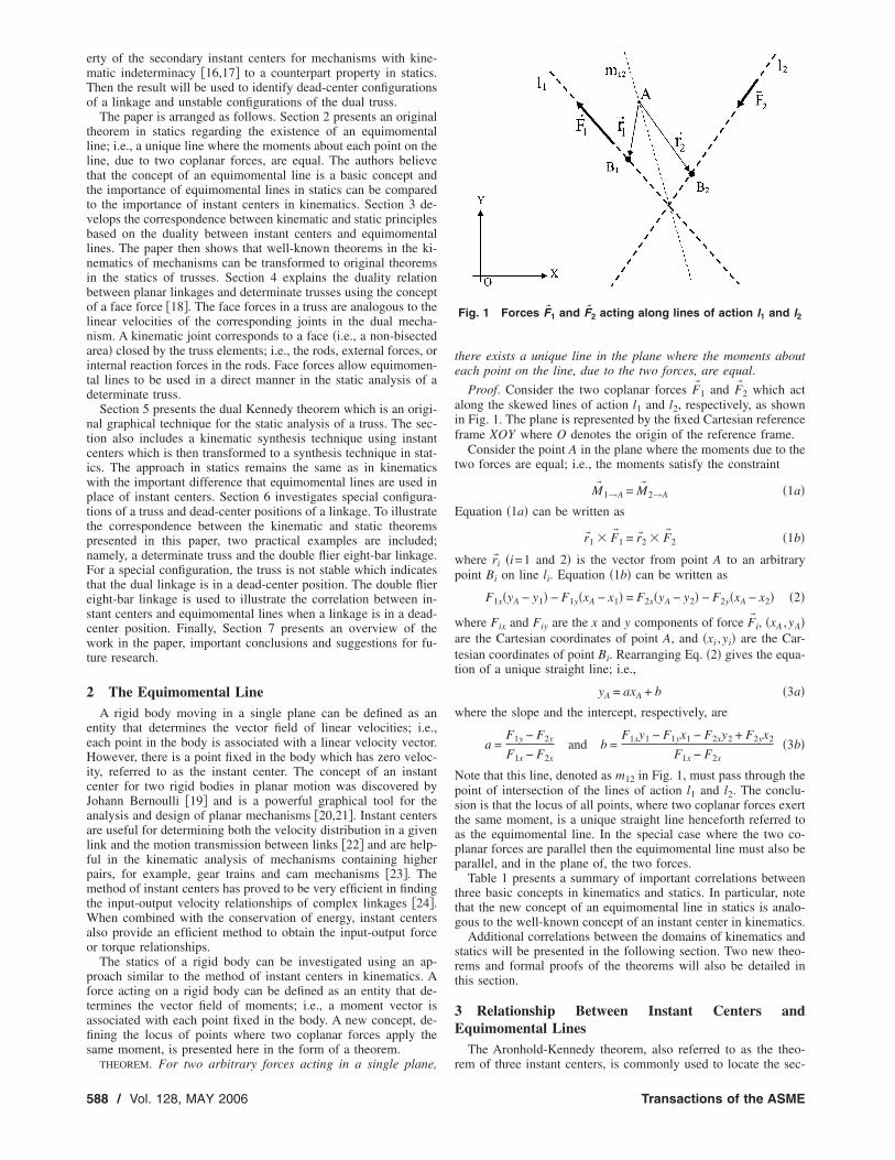
Proof. Consider the two coplanar forces F� 1 and F� 2 which actalong the skewed lines of action l1 and l2, respectively, as shownin Fig. 1. The plane is represented by the fixed Cartesian referenceframe XOY where O denotes the origin of the reference frame.
Consider the point A in the plane where the moments due to thetwo forces are equal; i.e., the moments satisfy the constraint
M� 1→A = M� 2→A �1a�Equation �1a� can be written as
r�1 � F� 1 = r�2 � F� 2 �1b�
where r�i �i=1 and 2� is the vector from point A to an arbitrarypoint Bi on line li. Equation �1b� can be written as
F1x�yA − y1� − F1y�xA − x1� = F2x�yA − y2� − F2y�xA − x2� �2�
where Fix and Fiy are the x and y components of force F� i, �xA ,yA�are the Cartesian coordinates of point A, and �xi ,yi� are the Car-tesian coordinates of point Bi. Rearranging Eq. �2� gives the equa-tion of a unique straight line; i.e.,
yA = axA + b �3a�where the slope and the intercept, respectively, are
a =F1y − F2y
F1x − F2xand b =
F1xy1 − F1yx1 − F2xy2 + F2yx2
F1x − F2x�3b�
Note that this line, denoted as m12 in Fig. 1, must pass through thepoint of intersection of the lines of action l1 and l2. The conclu-sion is that the locus of all points, where two coplanar forces exertthe same moment, is a unique straight line henceforth referred toas the equimomental line. In the special case where the two co-planar forces are parallel then the equimomental line must also beparallel, and in the plane of, the two forces.
Table 1 presents a summary of important correlations betweenthree basic concepts in kinematics and statics. In particular, notethat the new concept of an equimomental line in statics is analo-gous to the well-known concept of an instant center in kinematics.
Additional correlations between the domains of kinematics andstatics will be presented in the following section. Two new theo-rems and formal proofs of the theorems will also be detailed inthis section.
3 Relationship Between Instant Centers andEquimomental Lines
The Aronhold-Kennedy theorem, also referred to as the theo-
Fig. 1 Forces F� 1 and F� 2 acting along lines of action l1 and l2
rem of three instant centers, is commonly used to locate the sec-
Transactions of the ASME
ondary �or the unknown� instant centers of a single-degree-of-freedom planar mechanism �22�. The theorem states that theinstant centers associated with links i, j, and k of the mechanism�denoted here as Iij, Iik, and Ijk� must lie on a unique straight line.This theorem will now be transformed to the domain of staticsresulting in a new theorem, henceforth referred to as the equimo-mental line theorem.
THE EQUIMOMENTAL LINE THEOREM. The three equimomentallines defined by three arbitrary coplanar forces must intersect at aunique point.
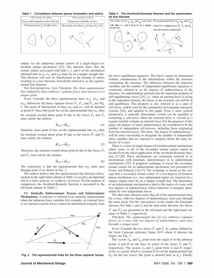
Proof. Consider the three equimomental lines m12, m13, and
m23, defined by the three coplanar forces F� 1, F� 2, and F� 3, see Fig.2. The point of intersection of lines m12 and m13 will be denotedas point D. Since this point lies on the equimomental line m12 then
the moment exerted about point D due to the forces F� 1 and F� 2must satisfy the relation
M� 1D = M� 2D �4�
Similarly, since point D lies on the equimomental line m13 then
the moment exerted about point D due to the forces F� 1 and F� 3must satisfy the relation
M� 1D = M� 3D �5�
Therefore, the moment exerted about point D due to the forces F� 2
and F� 3 must satisfy the relation
M� 2D = M� 3D �6�
The conclusion is that the equimomental line m23 must passthrough point D as shown in Fig. 2.
The authors believe that the equimomental line theorem �docu-mented in the right-hand column of Table 2� can play an importantrole in a static analysis, or synthesis, of trusses. For the purpose ofcomparison, the Aronhold-Kennedy theorem is presented in theleft-hand column of Table 2.
3.1 Statically Indeterminate Trusses and IndeterminateMechanisms. A structure is referred to as statically indeterminatewhen the unknown force variables �for example, an external forceor an internal reaction force� cannot be determined uniquely from
Table 1 Correlations between planar kinematics and statics
Fig. 2 The equimomental lines for the three coplanar forces
Journal of Mechanical Design
the force equilibrium equations. The forces cannot be determinedwithout consideration of the deformations within the elementsconstituting the structure. The difference between the unknownvariables and the number of independent equilibrium equations iscommonly referred to as the degrees of indeterminacy of thestructure. An indeterminate structure has the important property ofself-equilibrating forces �25�, i.e., when an internal force is actingin the redundant element, the forces in the structure can still be inself-equilibrium. This property is also referred to as a state ofself-stress, widely used by the community investigating tensegritysystems �26�, and adopted in this paper. From a more generalperspective, a statically determinate system can be regarded ascontaining a self-stress when the external force is viewed as aregular rod that contains an internal force. For the purposes of thispaper, the degrees of static indeterminacy are considered to be thenumber of independent self-stresses, including those originatingfrom the external forces. The term, “the degree of indeterminacy,”will be used consistently to designate the number of independentforce variables that are required to uniquely define the static be-havior of a truss.
There is a class of single-degree-of-freedom planar mechanismswhere some, or all, of the secondary instant centers cannot belocated from the direct application of the Aronhold-Kennedy theo-rem �27,28�. These mechanisms are commonly referred to asmechanisms with kinematic indeterminacy or as indeterminatemechanisms �29�. A graphical technique to locate the secondaryinstant centers for an indeterminate mechanism was presented byFoster and Pennock �16,17�. The technique is based on the con-cept that a secondary instant center of a two-degrees-of-freedomplanar mechanism �i.e., two independent inputs are required for aunique output� must lie on a unique straight line. The kinematicsof an indeterminate mechanism is dual to the statics of a truss withtwo degrees of indeterminacy whose behavior is uniquely deter-mined by two independent forces.
The dual static theorem states that all of the equimomental linesfor a truss, with two degrees of indeterminacy, must pass throughthe same point. For the convenience of the reader, the kinematictheorem �for links i and j� and the dual static theorem �for forces
F� i and F� j� are presented in the left-hand and the right-hand col-umns of Table 3, respectively.
THEOREM. The equimomental line for two arbitrary coplanarforces, in a truss with two degrees of indeterminacy, must passthrough a unique point.
Proof. Consider the two forces F� i and F� j in a plane defined bythe fixed Cartesian reference frame XOY where O denotes theorigin, see Fig. 3.
The vectors r�Oi and r�Oj point from the origin O to the arbitrary
points A and B on the lines of action of the forces F� i and F� j,respectively. The vectors r�iI and r� jI point from A and B, respec-tively, to a point which is assumed to lie on the equimomental line
Table 2 The Aronhold-Kennedy theorem and the equimomen-tal line theorem
mij for the two forces �the point is denoted here as Eij�. Finally,
MAY 2006, Vol. 128 / 589

the vector r�I �=xIi+yI j� points from the origin O to the point Eij.
The moment due to the two forces F� i and F� j, with respect to thepoint Eij, can be written as
M� Eij= M� O − �xIi + yI j� � �F� i − F� j� �7�
where M� O is the moment about point O, and xI and yI are theCartesian coordinates of point Eij. For convenience, Eq. �7� can bewritten as
M� Eij= M� O − �xIi + yI j� � F� ij �8a�
where
F� ij = F� i − F� j �8b�
is referred to as the force difference vector. Since point Eij isassumed to lie on the equimomental line mij then the momentabout this point due to the two forces is zero; i.e.,
M� Eij= M� Ei
− M� Ej= 0 �9�
where M� Eiis the moment about Eij due to F� i and M� E j
is the
moment about Eij due to F� j. Substituting Eq. �9� into Eq. �8a�, andrearranging, the moment about point O can be written as
M� O = �xIi + yI j��F� ij �10�
Table 3 Kinematic theorem and the dual static theorem
Fig. 3 Point Eij which lies on the equimomental line of two� �
forces Fi and Fj590 / Vol. 128, MAY 2006
As stated previously, the static behavior of a truss with twostates of self-stress �i.e., two degrees of indeterminacy� can bedefined by two independent force variables. For the purposes ofintroducing the dual of the kinematic theorem �17� into statics,these two forces will be referred to here as generalized forces anddenoted as p1 and p2. The generalized forces are analogous to thegeneralized velocities that are used in the kinematics theorem.Therefore, the moment about point O can be expressed as a linearcombination of the two generalized forces; i.e.,
MO = hM1p1 + hM2
p2 �11a�
where the coefficients
hM1=
�MO
�p1and hM2
=�MO
�p2�11b�
Sign convention: Since Eq. �11a� is a scalar equation then theequation gives a positive value if the moment is counterclockwiseand the equation gives a negative value if the moment isclockwise.
The Cartesian components of the force difference vector, seeEq. �8b�, can be expressed as linear combinations of the two gen-eralized forces; i.e.,
Fxij= fx1
p1 + fx2p2 �12a�
and
Fyij= fy1
p1 + fy2p2 �12b�
where the coefficients
fx1=
�Fxij
�p1, fx2
=�Fxij
�p2, fy1
=�Fyij
�p1and fy2
=�Fyij
�p2�13�
The equation of the equimomental line, see Eq. �3a�, can be writ-ten as
yI = axI + b �14a�where the slope and the intercept can be written, respectively, as
a =Fyij
Fxij
and b = −MO
Fxij
�14b�
Substituting Eqs. �11a� and �12� into Eqs. �14b�, the slope and theintercept of the equimomental line can be written as
a =fy1
p1 + fy2p2
fx1p1 + fx2
p2and b = −
hM1p1 + hM2
p2
fx1p1 + fx2
p2�15�
The ratio of the two generalized forces, henceforth referred as theforce ratio, will be defined as
rf =p2
p1�16�
Substituting Eq. �16� into Eq. �15�, and simplifying, the slope andthe intercept of the equimomental line can be written as
a =fy1
+ fy2rf
fx1+ fx2
rfand b = −
hM1+ hM2
rf
fx1+ fx2
rf�17�
Rearranging these two equations, the force ratio can be written as
rf =afx1
− fy1
fy2− afx2
or as rf = −bfx1
+ hM1
hM2+ bfx2
�18�
Then equating these two relations, and rearranging, gives
fy1hM2
− fy2hM1
fx1fy2
− fy1fx2
= a� fx1hM2
− fx2hM1
fx1fy2
− fy1fx2
� + b �19�
Note that Eq. �19� is the equation of a straight line �in the fixedCartesian reference frame in the plane of the forces�. From inspec-
tion of Eq. �19�, a point with the Cartesian coordinatesTransactions of the ASME
x0 =fx1
hM2− fx2
hM1
fx1fy2
− fy1fx2
and y0 =fy1
hM2− fy2
hM1
fx1fy2
− fy1fx2
�20�
must lie on this unique straight line. Therefore, independent of thegeneralized forces p1 and p2 the equimomental line for the two
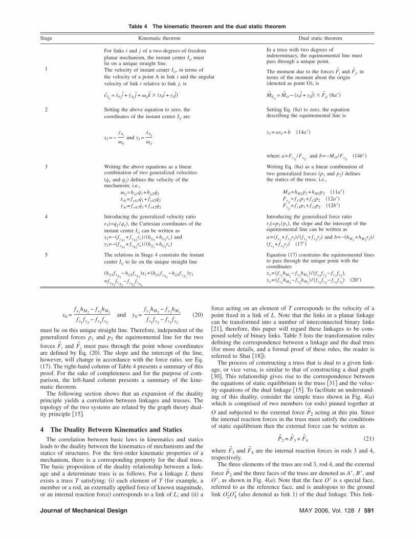
forces F� i and F� j must pass through the point whose coordinatesare defined by Eq. �20�. The slope and the intercept of the line,however, will change in accordance with the force ratio, see Eq.�17�. The right-hand column of Table 4 presents a summary of thisproof. For the sake of completeness and for the purpose of com-parison, the left-hand column presents a summary of the kine-matic theorem.
The following section shows that an expansion of the dualityprinciple yields a correlation between linkages and trusses. Thetopology of the two systems are related by the graph theory dual-ity principle �15�.
4 The Duality Between Kinematics and StaticsThe correlation between basic laws in kinematics and statics
leads to the duality between the kinematics of mechanisms and thestatics of structures. For the first-order kinematic properties of amechanism, there is a corresponding property for the dual truss.The basic proposition of the duality relationship between a link-age and a determinate truss is as follows. For a linkage L thereexists a truss T satisfying: �i� each element of T �for example, amember or a rod, an externally applied force of known magnitude,
Table 4 The kinematic theor
Stage Kinematic theorem
For links i and j of a two-degrees-of-freedomplanar mechanism, the instant center Iij mustlie on a unique straight line.
1 The velocity of instant center Iij, in terms ofthe velocity of a point A in link i and the anvelocity of link i relative to link j, is
v� Iij= xAi
i + yAij + �ijk � �xIi + yI j�
2 Setting the above equation to zero, thecoordinates of the instant center Iij are
xI = −yAi
�ijand yI =
xAI
�ij
3 Writing the above equations as a linearcombination of two generalized velocities�q1 and q2� defines the velocity of themechanism; i.e.,
�ij =hij1q1+hjj2q2
xAi= fxA1q1+ fxA2q2
yAi= fyA1q1+ fyA2q2
4 Introducing the generalized velocity ratiorV�=q2 / q1�, the Cartesian coordinates of theinstant center Iij can be written asxI=−�fyA1
+ fyA2rv� / �hij1
+hij2rv� and
yI=−�fxA1+ fxA2
rv� / �hij1+hij2
rv�
5 The relations in Stage 4 constrain the instantcenter Iij to lie on the unique straight line
�hij1fxA2−hij2fxA1
�x1+ �hij1fyA2−hij2fyA1
�y1
=fxA1fyA2
− fxA2fyA1
or an internal reaction force� corresponds to a link of L; and �ii� a
Journal of Mechanical Design
force acting on an element of T corresponds to the velocity of apoint fixed in a link of L. Note that the links in a planar linkagecan be transformed into a number of interconnected binary links�21�, therefore, this paper will regard these linkages to be com-posed solely of binary links. Table 5 lists the transformation rulesdefining the correspondence between a linkage and the dual truss�for more details, and a formal proof of these rules, the reader isreferred to Shai �18��.
The process of constructing a truss that is dual to a given link-age, or vice versa, is similar to that of constructing a dual graph�30�. This relationship gives rise to the correspondence betweenthe equations of static equilibrium in the truss �31� and the veloc-ity equations of the dual linkage �15�. To facilitate an understand-ing of this duality, consider the simple truss shown in Fig. 4�a�which is comprised of two members �or rods� pinned together at
O and subjected to the external force P� 2 acting at this pin. Sincethe internal reaction forces in the truss must satisfy the conditionsof static equilibrium then the external force can be written as
P� 2 = F� 3 + F� 4 �21�
where F� 3 and F� 4 are the internal reaction forces in rods 3 and 4,respectively.
The three elements of the truss are rod 3, rod 4, and the external
force P� 2 and the three faces of the truss are denoted as A�, B�, andO�, as shown in Fig. 4�a�. Note that the face O� is s special face,referred to as the reference face, and is analogous to the ground
and the dual static theorem
Dual static theorem
In a truss with two degrees ofindeterminacy, the equimomental line mustpass through a unique point.
rThe moment due to the forces F� i and F� j, interms of the moment about the origin�denoted as point O�, is
M� Eij= M� O − �xIi + yI j� � F� ij �8a��
Setting Eq. �8a� to zero, the equationdescribing the equimomental line is
yI = axI + b �14a��
where a=Fyij/Fxij
and b=−MO /Fxij�14b��
Writing Eq. �8a� as a linear combination oftwo generalized forces �p1 and p2� definesthe statics of the truss; i.e.,
MO=hM1p1+hM2p2 �11a��Fxij
= fx1p1+ fx2p2 �12a��Fyij
= fy1p1+ fy2p2 �12b��
Introducing the generalized force ratiorf�=p2 / p1�, the slope and the intercept of theequimomental line can be written as
a= �fy1+ fy2
rf� / �fx1+ fx2
rf� and b=−�hM1+hM2
rf� /�fx1
+ fx2rf� �17��
Equation �17� constrains the equimomental linesto pass through the unique point with thecoordinatesxo= �fx1
hM2− fx2
hM1� / �fx1
fy2− fy1
fx2�,
yo= �fy1hM2
− fy2hM1
� / �fx1fy2
− fy1fx2
� �20��
em
gula
link O2�O4� �also denoted as link 1� of the dual linkage. This link-
MAY 2006, Vol. 128 / 591

age can be obtained from the transformation rules that are pre-sented in Table 5. The result is a planar four-bar linkage com-prised of the ground link 1, the input �or driving� link 2�, thecoupler link 3�, and the output link 4�, as shown in Fig. 4�b�.Links 2� and 4� are pinned to the ground link 1 at O2� and O4�,respectively, and pinned to link 3� at A and B. Note that joints Aand B of the dual linkage are analogous to faces A� and B� of thesimple truss. Also, note that links 2�, 3�, and 4� correspond to theelements 2, 3, and 4 of the truss, respectively, such that each linkis perpendicular to the corresponding element in the truss, as il-lustrated in Fig. 4�a�. This construction guarantees that the direc-tion of a force in the truss is parallel to either the absolute velocityof a joint or the relative velocity between two joints in the duallinkage; i.e., there is a geometrical isomorphism between the trussand the dual linkage.
In addition, there is a topological isomorphism between theelements of the truss and the links of the dual linkage. To illustratethis, consider pin A which connects the input link 2� and thecoupler link 3�, see Fig. 4�b�. The linear velocity of pin A �i.e., theinput velocity� can be written as
V� A = V� B + V� A/B �22�A comparison of Equations �21� and �22� shows the topologicalisomorphism between the elements in the truss and the links in thedual linkage. The conclusion is that there is a correspondencebetween the forces in the truss elements �due to the external force
Table 5 Transformation rules
Linkage terminology
A link; i.e., a rigid body which can be regarded as infinite in extent.
A kinematic pair or a joint �e.g., a revolute joint or a prismatic joint�.The relative velocity between the two kinematic pairs of a binary link;i.e., the vector difference of the absolute velocities of the two kinematicpairs.The absolute linear velocity of a joint.
The number of degrees of freedom of the linkage.
Fig. 4 Example of the truss-linkage duality. „a… A simple truss„the dual linkage is superimposed…. „b… The dual linkage.
Table 6 Dual properties
The relative instant center of two links connected by a revolute joint iscoincident with the revolute joint.
The ground link.
The input �or driving� link.
If the relative instant center Iij is coincident with the absolute instantcenter I1i then the linkage is immobile �or locked�.The linkage is mobile if, and only if, there exists a set of all possibleinstant centers that satisfy the Aronhold-Kennedy theorem.
592 / Vol. 128, MAY 2006
P� 2� and the linear velocities of the joints in the dual linkage �due
to the input velocity V� A�. Since the truss can be scaled up or downwithout affecting the magnitudes of the internal forces in members3 and 4 then the lengths of links 3� and 4� can also be scaled upor down without affecting the velocity of pin B or the velocity ofpin A relative to pin B.
A face force is the most suitable entity to introduce equimo-mental lines into the static analysis of a truss. This force variable,which is defined in Table 5, is associated with each face of thetruss and can be considered the multidimensional expansion of themesh currents in an electronic circuit �18�. An internal reactionforce acting in a member of a truss, denoted as member j, can bewritten as
F� j = F� R − F� L �23�
where F� R and F� L are the face forces of the two adjacent faces onthe right and left sides �or planes�, respectively, of member j. Theright and left planes are defined according to the direction of theedge; i.e., the unit vector pointing from the head vertex to the tailvertex �15�. The equimomental line of the two face forces coin-cides with the vector difference of the two forces �see Sec. 2�.Therefore, the equimomental line of two adjacent face forces isparallel to the line of the rod, the line of action of the externalforce, or the line of action of the internal reaction force separatingthe two faces. To indicate the importance of a face force, Table 6lists a number of dual properties between a planar mechanism anda truss.
The following section will present an original graphical tech-nique, referred to here as the dual Kennedy theorem, to locate theunknown equimomental lines of a simple truss. After the locationsof the equimomental lines are known then the face forces and theunknown reaction forces acting in the truss can be determined. Anadvantage of this graphical technique, compared to an analyticaltechnique, is that the internal reaction force in a specified rod canbe obtained directly without the need to evaluate the internal re-action forces in other rods of the truss.
5 The Dual Kennedy TheoremThe dual Kennedy theorem and the face force relationship of a
determinate truss are summarized in the right-hand column of
r a linkage and the dual truss
Truss terminology
A truss element �e.g., a rod, an external force, or an internal reactionforce�.A face; i.e., the area of a plane enclosed by the truss elements.The force in a truss element.
The face force �defined as the force associated with each face of thetruss�.The number of degrees of indeterminacy of the truss.
mechanism and a truss
The equimomental line of two adjacent face forces is the line whichseparates the two face forces.The reference face. The face of the truss where, without loss ofgenerality, the face force is taken to be zero. It is common practice tochose the outside area of the truss to be the reference face.The input �or specified� face force. In general, this is the force in theface located on one side of the external force.If the corresponding equimomental line mxy is coincident with theequimomental line mzy then the truss is not rigid.A truss is stable if, and only if, there exists a set of all possibleequimomental lines that satisfy the equimomental line theorem.
fo
of a
Transactions of the ASME

Table 7. For the convenience of the reader and for the purpose ofcomparison, the Aronhold-Kennedy theorem and the angular ve-locity relationship of a single-degree-of-freedom planar mecha-nism are summarized in the left-hand column.
The sign convention for Eq. �24� is well-known; i.e., use thenegative sign if the relative instant center I2i lies between the twoabsolute instant centers I21 and Ii1 and use the positive sign if therelative instant center lies outside the two absolute instant centers.
The sign convention for Eq. �25� can be obtained in a system-atic manner from the sign convention for Eq. �24� using the dual-ity relation. The location of the relative instant center with respectto the absolute instant centers is replaced by the direction of theface forces with respect to the two half-planes formed by therelative equimomental line. Therefore, use the positive sign in Eq.
�25� if the face forces F� K and F� P acting along the absolute equi-momental lines mKO and mPO, respectively, are both directedfrom one side of the half-plane created by the relative equimo-mental line mPK to the other side of the half-plane. Similarly, usethe negative sign in Eq. �25� if the two forces are not both directedfrom one side of the half-plane created by the relative equimo-mental line to the other side of the half-plane.
To illustrate the dual Kennedy theorem and the sign conventionconsider the simple truss �commonly referred to as the Howetruss� shown in Fig. 5�a�, in which the common assumption ofpinned joints is implied. The truss is subjected to a known exter-
nal force P� which acts at the pin connecting the five rods 5, 6, 8,9, and 11.
A typical statics problem is to determine the internal reactionforce in a particular rod of the idealized truss. For the purposes ofillustration, assume that the problem is to determine the internalreaction force in the lower rod 7.
Recall that a conventional analytical approach to solve a stati-cally determinate truss problem is to write the force balance equa-tions for the members of the truss. This produces a set of simul-taneous linear equations which can be solved in a straight-forwardmanner using a computer software package, such as MATLAB orMATHEMATICA. However, this procedure affords no geometric in-
Table 7 The Aronhold-Kennedy the
Summary of the Aronhold-Kennedy theorem to find the instant centersof a planar mechanism:1. Map all the kinematic pairs as the instant centers of the connectedlinks.2. Find a set of four links �say i, j, k, and l� for which the relativeinstant centers Iij, Iik, Ikl, and Iil are known.3. The point of intersection of the line connecting instant centers Iij andIjk, and the line connecting instant centers Ii1 and Ik1 is the instantcenter Iik.4. Repeat this procedure to locate all the unknown instant centers.To facilitate the application of this method, use the Kennedy circle asfollows. Associate each link with a vertex on the circle. If the locationof the instant center between two links is known then connect the twocorresponding vertices with an edge. Step 2 is the search for aquadrangle formed by the edges in the circle, while step 3 results in theaddition of a diagonal to that quadrangle.
The angular velocity of link i can be written in terms of the inputangular velocity �2 as
�i = ±I2iI21
I2iIi1�2 �24�
where 1 denotes the ground link and I2iIi1 and I2iI21 are the distancesbetween instant centers I2i and Ii1 and between instant centers I2i andI2l, respectively. Equation �24� takes advantage of the fact that thepoints on two links, which are coincident with the relative instantcenter, have the same linear velocity.
sight and the internal forces in several of the rods must be evalu-
Journal of Mechanical Design
ated before the internal force in rod 7 can be obtained. Note thatthe graphical technique proposed here does not require a knowl-edge of the internal forces in the other rods in order to determinethe internal force in a specified rod. This graphical technique isbelieved to be an original contribution to the literature and issimilar to drawing the Aronhold-Kennedy circle to locate the sec-ondary instant centers of a single-degree-of-freedom planar
em and the dual Kennedy theorem
Summary of the dual Kennedy theorem to find the equimomental linesof a determinate truss:1. Map all the rods as the equimomental lines of the faces theyseparate.2. Find a set of four face forces �say x, y, z, and w� for which theequimomental lines mxy, myz, mwx, and mwz, are known.3. The line connecting the point of intersection of equimomental linesmxy and myz, and the point of intersection of equimomental lines mwx
and mwz is the equimomental line is mxz.4. Repeat this procedure to locate all the unknown equimomental lines.To facilitate the application of this method, use the dual Kennedy circleas follows. Associate each face with a vertex on the circle. If thelocation of the equimomental line between two face forces is knownthen connect the two corresponding vertices with an edge. Step 2 is thesearch for a quadrangle formed by the edges in the circle, while step 3results in the addition of a diagonal to the quadrangle.
The face force of face K can be written in terms of the face force FP�i.e., the known external force� as
FK = ±mPKmPO
mPKmKOFP �25�
where O denotes the reference face and mPKmKO and mPKmPO are theperpendicular distances from an arbitrary point on the relativeequimomental line mPK to the absolute equimomental lines mKO, andmPO, respectively. Equation �25� takes advantage of the fact that twocoplanar forces apply the same moment at each point on theequimomental line of these two forces.
or
Fig. 5 „a… A simple truss. „b… The faces of the simple truss.
MAY 2006, Vol. 128 / 593
mechanism �20,22�. For this reason the technique is referred tohere as drawing the dual Kennedy circle.
The number of faces of this truss is n=9 and are denoted as A,B, C, D, E, F, G, P, and O as shown in Fig. 5�b�. The referenceface is denoted as O and the input face is denoted as P. Note thatthe external force is between the input face P on the left and thereference face O on the right. Since the face force in the reference
face is defined as zero then the external force P� is the face force offace P; i.e., denoted here as FP.
The total number of equimomental lines in this truss is
nl =n�n − 1�
2=
9�9 − 1�2
= 36 �26�
The number of known �or primary� equimomental lines can bewritten as
nK = nR + nE + nS �27a�
where the number of rods nR=13, the number of external forcesacting on the truss nE=1, and the number of mobile supports nS=1. Therefore, the number of primary equimomental lines is
nK = 13 + 1 + 1 = 15 �27b�The number of unknown �or secondary� equimomental lines is
nU = 36 − 15 = 21 �28�The procedure to locate the secondary equimomental lines is to
draw a circle �referred to as the dual Kennedy circle� and denotethe faces of the truss in a clockwise manner on the circumferenceof this circle, see Fig. 6�a�. Then represent the primary equimo-mental lines as solid lines and the secondary equimomental linesas dashed lines in this circle. For example, the secondary equimo-mental lines mPG, mPC, and mCO are indicated by the dashed lineson Figs. 6�b�–6�d�, respectively.
Note that the dashed line PG creates the two triangles POG andPAG in the quadrangle OPAG, see Fig. 6�b�. Therefore, the equi-momental line mPG must pass through: �i� the point of intersectionof equimomental lines mPA and mAG, namely, between the lines ofrods 2 and 4, respectively, and �ii� the point of intersection of theequimomental line mPO �i.e., the line coincident with the line of
action of the external force P� � and the equimomental line mGO�i.e., the line coincident with the line of action of the reactionforce r��. Similarly, the dashed line PC creates the two trianglesCBP and CGP in the quadrangle BCGP, see Fig. 6�c�. Therefore,the equimomental line mPC must pass through: �i� the point ofintersection of equimomental lines mPB and mBC, namely, betweenthe lines of rods 5 and 6, respectively, and �ii� the point of inter-section of the equimomental line mPG and the equimomental linemCG which is coincident with rod 7. Finally, the dashed line OC
Fig. 6 The dual Kennedy circle „a… The primary equimomentallines. „b… The secondary equimomental line mPG. „c… The sec-ondary equimomental line mPC. „d… The secondary equimomen-tal line mCO.
creates the two triangles OPC and OGC in the quadrangle OPCG,
594 / Vol. 128, MAY 2006
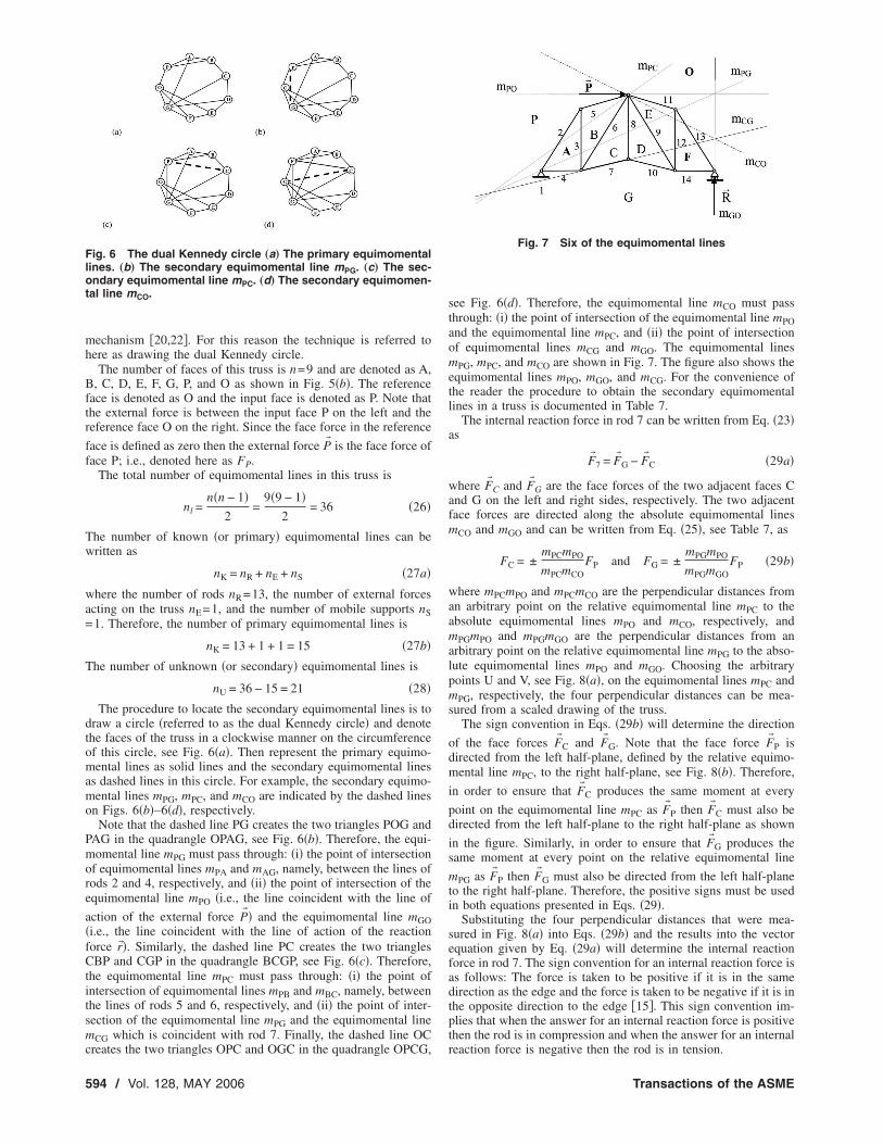
see Fig. 6�d�. Therefore, the equimomental line mCO must passthrough: �i� the point of intersection of the equimomental line mPOand the equimomental line mPC, and �ii� the point of intersectionof equimomental lines mCG and mGO. The equimomental linesmPG, mPC, and mCO are shown in Fig. 7. The figure also shows theequimomental lines mPO, mGO, and mCG. For the convenience ofthe reader the procedure to obtain the secondary equimomentallines in a truss is documented in Table 7.
The internal reaction force in rod 7 can be written from Eq. �23�as
F� 7 = F� G − F� C �29a�
where F� C and F� G are the face forces of the two adjacent faces Cand G on the left and right sides, respectively. The two adjacentface forces are directed along the absolute equimomental linesmCO and mGO and can be written from Eq. �25�, see Table 7, as
FC = ±mPCmPO
mPCmCOFP and FG = ±
mPGmPO
mPGmGOFP �29b�
where mPCmPO and mPCmCO are the perpendicular distances froman arbitrary point on the relative equimomental line mPC to theabsolute equimomental lines mPO and mCO, respectively, andmPGmPO and mPGmGO are the perpendicular distances from anarbitrary point on the relative equimomental line mPG to the abso-lute equimomental lines mPO and mGO. Choosing the arbitrarypoints U and V, see Fig. 8�a�, on the equimomental lines mPC andmPG, respectively, the four perpendicular distances can be mea-sured from a scaled drawing of the truss.
The sign convention in Eqs. �29b� will determine the direction
of the face forces F� C and F� G. Note that the face force F� P isdirected from the left half-plane, defined by the relative equimo-mental line mPC, to the right half-plane, see Fig. 8�b�. Therefore,
in order to ensure that F� C produces the same moment at every
point on the equimomental line mPC as F� P then F� C must also bedirected from the left half-plane to the right half-plane as shown
in the figure. Similarly, in order to ensure that F� G produces thesame moment at every point on the relative equimomental line
mPG as F� P then F� G must also be directed from the left half-planeto the right half-plane. Therefore, the positive signs must be usedin both equations presented in Eqs. �29�.
Substituting the four perpendicular distances that were mea-sured in Fig. 8�a� into Eqs. �29b� and the results into the vectorequation given by Eq. �29a� will determine the internal reactionforce in rod 7. The sign convention for an internal reaction force isas follows: The force is taken to be positive if it is in the samedirection as the edge and the force is taken to be negative if it is inthe opposite direction to the edge �15�. This sign convention im-plies that when the answer for an internal reaction force is positivethen the rod is in compression and when the answer for an internal
Fig. 7 Six of the equimomental lines
reaction force is negative then the rod is in tension.
Transactions of the ASME
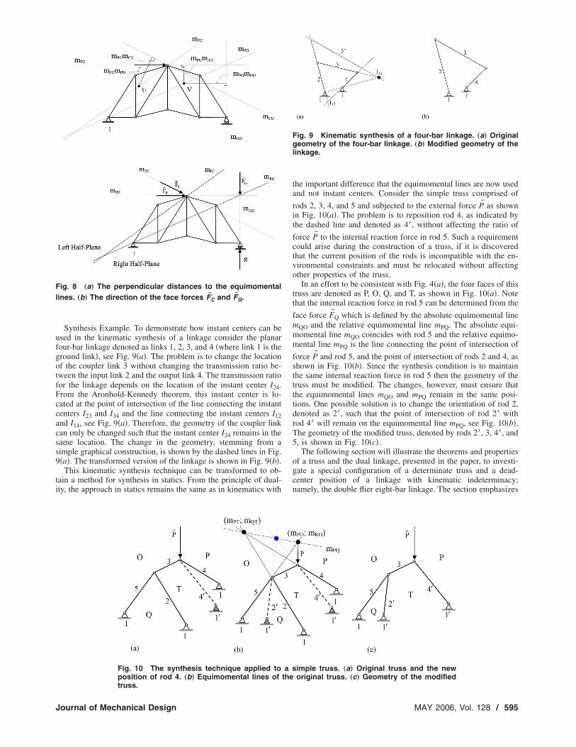
Synthesis Example. To demonstrate how instant centers can beused in the kinematic synthesis of a linkage consider the planarfour-bar linkage denoted as links 1, 2, 3, and 4 �where link 1 is theground link�, see Fig. 9�a�. The problem is to change the locationof the coupler link 3 without changing the transmission ratio be-tween the input link 2 and the output link 4. The transmission ratiofor the linkage depends on the location of the instant center I24.From the Aronhold-Kennedy theorem, this instant center is lo-cated at the point of intersection of the line connecting the instantcenters I23 and I34 and the line connecting the instant centers I12and I14, see Fig. 9�a�. Therefore, the geometry of the coupler linkcan only be changed such that the instant center I24 remains in thesame location. The change in the geometry, stemming from asimple graphical construction, is shown by the dashed lines in Fig.9�a�. The transformed version of the linkage is shown in Fig. 9�b�.
This kinematic synthesis technique can be transformed to ob-tain a method for synthesis in statics. From the principle of dual-ity, the approach in statics remains the same as in kinematics with
Fig. 8 „a… The perpendicular distances to the equimomentallines. „b… The direction of the face forces F� C and F� G.
Fig. 10 The synthesis technique applied toposition of rod 4. „b… Equimomental lines of
truss.Journal of Mechanical Design
the important difference that the equimomental lines are now usedand not instant centers. Consider the simple truss comprised of
rods 2, 3, 4, and 5 and subjected to the external force P� as shownin Fig. 10�a�. The problem is to reposition rod 4, as indicated bythe dashed line and denoted as 4�, without affecting the ratio of
force P� to the internal reaction force in rod 5. Such a requirementcould arise during the construction of a truss, if it is discoveredthat the current position of the rods is incompatible with the en-vironmental constraints and must be relocated without affectingother properties of the truss.
In an effort to be consistent with Fig. 4�a�, the four faces of thistruss are denoted as P, O, Q, and T, as shown in Fig. 10�a�. Notethat the internal reaction force in rod 5 can be determined from the
face force F� Q which is defined by the absolute equimomental linemQO and the relative equimomental line mPQ. The absolute equi-momental line mQO coincides with rod 5 and the relative equimo-mental line mPQ is the line connecting the point of intersection of
force P� and rod 5, and the point of intersection of rods 2 and 4, asshown in Fig. 10�b�. Since the synthesis condition is to maintainthe same internal reaction force in rod 5 then the geometry of thetruss must be modified. The changes, however, must ensure thatthe equimomental lines mQO and mPQ remain in the same posi-tions. One possible solution is to change the orientation of rod 2,denoted as 2�, such that the point of intersection of rod 2� withrod 4� will remain on the equimomental line mPQ, see Fig. 10�b�.The geometry of the modified truss, denoted by rods 2�, 3, 4�, and5, is shown in Fig. 10�c�.
The following section will illustrate the theorems and propertiesof a truss and the dual linkage, presented in the paper, to investi-gate a special configuration of a determinate truss and a dead-center position of a linkage with kinematic indeterminacy;namely, the double flier eight-bar linkage. The section emphasizes
Fig. 9 Kinematic synthesis of a four-bar linkage. „a… Originalgeometry of the four-bar linkage. „b… Modified geometry of thelinkage.
simple truss. „a… Original truss and the neworiginal truss. „c… Geometry of the modified
athe
MAY 2006, Vol. 128 / 595

the correspondence between �i� a nonrigid truss and the dual link-age; and �ii� the equimomental lines in the double flier eight-barlinkage in an arbitrary configuration and a dead-center configura-tion.
6 Special ConfigurationsThe problem of finding unstable configurations of a truss is an
important problem in statics. Similarly, the problem of findingdead-center positions of a mechanism is an important problem inkinematics �20,21,32�. An algorithm for finding the dead-centerpositions for the given topology of a planar linkage was recentlydeveloped by Shai and Polansky �33�. Also, a study of dead-centerpositions of single-degree-of-freedom planar linkages using Assurkinematic chains was presented by Pennock and Kamthe �34�. Theexamples presented in this section will use the concepts developedin this paper to identify dead-center positions of a mechanism.This procedure will not only determine if a truss is unstable or amechanism is in a dead-center position, but will also identify thedependence between the locations of elements in the system �trussor mechanism� which causes the system to be in such a configu-ration. It is commonly accepted that obtaining solutions to thislatter problem is not a straight-forward task.
6.1 A Determinate Truss. Consider the truss shown in Fig.
11�a� which is subjected to a known external force P� 2 acting at thepin connecting rods 4, 6, and 7. Note that this truss is in a specialconfiguration; i.e., rods 3, 7, and 8 �or the extension of the threerods� intersect at a single point. The five faces of this truss will bedenoted as A, B, C, D, and E. Faces B and D are adjacent facesseparated by rod 8, therefore, the equimomental line mBD is coin-cident with rod 8, as shown in Fig. 11�b�. Similarly, the equimo-mental line mDE is coincident with rod 3, the equimomental linemAB is coincident with rod 7, and the equimomental line mAE is
coincident with the line of action of the external force P� 2.According to the dual statics theorem, the equimomental line
mBE �for the two face forces B and E� is obtained by connectingthe points of intersection of: �i� the equimomental lines mBD andmDE; and �ii� the equimomental lines mAB and mAE. Therefore, theequimomental line mBE is the line connecting the point of inter-section of rods 3, 7, and 8 �or the rods extended� and the pinconnecting rods 4, 6, and 7. In other words, the equimomental linemBE is coincident with rod 7 �or the equimomental line mAB�, seeFig. 5�b�. The conclusion is that the truss is unstable in this con-figuration �see row 4 of Table 6�.
The dual linkage, superimposed on the truss in Fig. 12�a� andshown separately in Fig. 12�b�, is a Stephenson-III six-bar linkagein a special configuration; i.e., links 3, 4, and 6 �or the extensionsof the links� intersect at a single point. According to the Aronhold-Kennedy theorem this unique point is the instant center for thecoupler link 5 �i.e., I15�, see Fig. 12�c�. Recall that the instant
Fig. 11 The rigidity of the truss. „a… The truss. „b… The equimo-mental line mBE.
center I13 is defined as the point of intersection of the line passing
596 / Vol. 128, MAY 2006
through the instant centers I12 and I23 and the line passing throughthe instant centers I15 and I35. Therefore, the instant center I13 iscoincident with the pin that connects links 2 and 3; i.e., I13 iscoincident with I23, as shown in Fig. 12�c�. This implies that thedual linkage is instantaneously locked in this configuration �seerow 4 of Table 6�; i.e., the input angular velocity is zero. The onlyconstraint for the linkage to be in this special configuration, com-monly referred to as a dead-center position, is that the instantcenter I15 be located on link 3 �or link 3 extended�.
6.2 The Double Flier Eight-Bar Linkage. This single-degree-of-freedom planar linkage is shown in an arbitrary con-figuration in Fig. 13�a�. The seven faces of the dual truss will bedenoted as A, B, C, D, E, F, and G, and for convenience are shownin Fig. 13�a�.
From the equimomental line theorem, see Table 7, the threeequimomental lines defined by faces A, F, and D �i.e., mAF, mFD,and mAD� must intersect at a single point. Link 3 separates faces Aand F, therefore, the line along link 3 is the equimomental linemAF. Similarly, link 4 separates faces D and F, therefore, the linealong link 4 is the equimomental line mFD. Therefore, the equi-momental line mAD must pass through the point of intersection oflinks 3 and 4. From a similar argument, the equimomental linemAD must also pass through the point of intersection of links 11and 13. Therefore, the equimomental line mAD is the line connect-ing these two points of intersection, see Fig. 13�a�. In the samemanner, the equimomental line mAB must pass through the pointof intersection of links 8 and 11, and the point of intersection oflink 7 and the equimomental line mAD. Finally, the equimomentalline mBF �if it exists for the double flier eight-bar linkage in thisconfiguration� must pass through the points of intersections of: �i�links 6 and 14, �ii� links 4 and 7, and �iii� the equimomental linemAB and link 3. Note that these three points, marked with circlesin Fig. 13�a�, do not lie on the same straight line. Therefore, theequimomental line mBF does not exist for the linkage in this con-figuration. The conclusion is that the linkage is instantaneouslymovable in the given configuration; i.e., the mobility is one.
Now consider the double flier eight-bar linkage in the configu-ration shown in Fig. 13�b�.
Note that the three points of intersections of: �i� links 6 and 14,�ii� links 4 and 7, and �iii� the equimomental line mAB and link 3,
Fig. 12 The dual linkage in a dead-center position. „a… Thenonrigid truss. „b… The dual linkage. „c… Instant center I13 iscoincident with instant center I23.
again marked with circles in Fig. 13�b�, now lie on the same
Transactions of the ASME

straight line; i.e., the equimomental line mBF. This indicates thatthe linkage is in a singular configuration. The linkage can resistexternally applied forces and instantaneously constitutes a struc-ture; i.e., the mobility is zero.
7 ConclusionsThe paper presents the duality relation between the domains of
planar kinematics and statics through two integrated levels: �i� thelevel of correlation between the basic concepts and theorems un-derlying these fields, and �ii� the level of duality between specificengineering systems. The paper introduces the concept of an equi-momental line which is a unique line where the moments abouteach point on the line, due to two arbitrary coplanar forces, areequal. The authors believe that equimomental lines are a funda-mental concept in statics and are a significant contribution to theliterature. Two theorems are then presented based on the dualitybetween equimomental lines and instantaneous centers of zerovelocity. The first theorem, referred to as the equimomental linetheorem, states that the three equimomental lines defined by threecoplanar forces must intersect at a unique point. The second theo-rem states that the equimomental line for two coplanar forces
Fig. 13 „a… Double flier eight-bar linkage in an arbitrary con-figuration. „b… The equimomental line mBF for a singularconfiguration.
acting in a truss with two degrees of indeterminacy must pass
Journal of Mechanical Design
through a unique point. The paper then uses the concept of a faceforce to introduce a graphical technique to locate the equimomen-tal lines of a determinate truss. This technique, referred to as thedual Kennedy theorem, is a dual form of the well-knownAronhold-Kennedy theorem in kinematics and is believed to be asignificant contribution to the literature.
The practical examples presented in this paper emphasize theduality that exists between kinematics and statics. For instance,fundamental principles in kinematics can be used to check thestability of determinate trusses and principles in statics can beused to check the dead-center positions of linkages. A well-knownrule in kinematics for checking if a linkage is in a dead-centerposition was transformed to statics to provide a new rule forchecking the rigidity of a truss. The results of this paper affordengineers from both domains the opportunity to solve commonproblems using these new concepts. In addition, research groupsin kinematics and statics will be able to share their knowledge andexpedite their research work. Since the paper operates on the edgebetween kinematics and statics, the results presented in this paperhave great potential for practical problems in kinetostatics. Thereis reason to believe that the duality relation can be applied toadditional types of engineering systems. Examples include de-ployable structures which have attracted the attention of the aero-nautics and astronautics community and tensegrity structureswhich have attracted the attention of the robotics and biologicalcommunities �35�.
The duality between determinate trusses and planar linkageswill yield a variety of practical and theoretical applications, in-cluding new engineering theorems and concepts, and the design ofnew systems. The authors believe that this paper makes a signifi-cant contribution to the theory of duality between planar kinemat-ics and statics and a stronger contribution to the teaching of thistheory. The authors hope that this duality will be developed fur-ther in order to derive new theorems in both the kinematics ofmechanisms and in the statics of a wide variety of structures. Theauthors continue to explore this possibility and a future paper willpresent several new concepts in the kinematic analysis and syn-thesis of both planar and spatial mechanisms and the statics ofstructures consisting of one-, two-, and three-dimensional compo-nents. Future work will also include analytical techniques tocomplement the graphical techniques that are the primary focus ofthis paper.
References�1� Girvin, S. M., 1996, “Duality in Perspective,” Science, 274�5287�, pp. 524–
525.�2� Pedoe, D., 1963, An Introduction to Projective Geometry, Pergamon Press,
Oxford, England.�3� Hsia, L. M., and Yang, A. T., 1981, “On The Principle of Transference in
Three-Dimensional Kinematics,” ASME J. Mech. Des., 103�3�, pp. 652–656.�4� Phillips, J., 1984, Freedom in Machinery, Vol. 1, Cambridge University Press,
England.�5� Pennock, G. R., and Yang, A. T., 1985, “Application of Dual-Number Matrices
to the Inverse Kinematics Problem of Robot Manipulators,” ASME J. Mech.,Transm., Autom. Des., 107�2�, pp. 201–208.
�6� Tarnai, T., 1989, “Duality between Plane Trusses and Grillages,” Int. J. SolidsStruct., 25�12�, pp. 1395–1409.
�7� Davies, T., 1983, “Mechanical Networks—III, Wrenches on Circuit Screws,”Mech. Mach. Theory, 18�2�, pp. 107–112.
�8� Waldron, K. J., and Hunt, K. H., 1991, “Series-Parallel Dualities in ActivelyCoordinated Mechanisms,” Int. J. Robot. Res., 10�5�, pp. 473–480.
�9� Gosselin, F., and Lallemand, J-P., 2001, “A New Insight into the Duality be-tween Serial and Parallel Non-Redundant and Redundant Manipulators,” Ro-botica, 19, pp. 365–370.
�10� Duffy, J., 1996, Statics and Kinematics with Applications to Robotics, Cam-bridge University Press, New York.
�11� Davidson, J. K., and Hunt, K. H., 2004, Robots and Screw Theory: Applica-tions of Kinematics and Statics to Robotics, Oxford University Press, NewYork.
�12� Shai, O., and Pennock, G. R., 2006, “Extension of Graph Theory to the DualityBetween Static Systems and Mechanisms,” ASME J. Mech. Des., 128�1�, pp.179–191.
�13� Ball, R. S., 2000, The Theory of Screws, Cambridge University Press, England.�Originally published in 1876 and revised by the author in 1900; now reprinted
with an introduction by H. Lipkin and J. Duffy�.MAY 2006, Vol. 128 / 597
�14� McGuire, W., Gallagher, R. H., and Ziemian, R. D., 2000, Matrix StructuralAnalysis, 2nd ed., Wiley, New York.
�15� Shai, O., 2001, “The Duality Relation between Mechanisms and Trusses,”Mech. Mach. Theory, 36�3�, pp. 343–369.
�16� Foster, D. E., and Pennock, G. R., 2003, “A Graphical Method to Find theSecondary Instantaneous Centers of Zero Velocity for the Double ButterflyLinkage,” ASME J. Mech. Des., 125�2�, pp. 268–274.
�17� Foster, D. E., and Pennock, G. R., 2005, “Graphical Methods to Locate theSecondary Instant Centers of Single-Degree-of-Freedom Indeterminate Link-ages,” ASME J. Mech. Des., 127�2�, pp. 249–256.
�18� Shai, O., 2002, “Utilization of the Dualism between Determinate Trusses andMechanisms,” Mech. Mach. Theory, 37�1�, pp. 1307–1323.
�19� Hartenberg, R. S., and Denavit, J., 1964, Kinematic Synthesis of Linkages,McGraw-Hill, New York.
�20� Waldron, K. J., and Kinzel, G. L., 2004, Kinematics, Dynamics, and Design ofMachinery, 2nd ed., Wiley, New York, Chaps. 2 and 4.
�21� Norton, R. L., 2001, Design of Machinery, McGraw-Hill, New York.�22� Uicker, J. J., Jr., Pennock, G. R., and Shigley, J. E., 2003, Theory of Machines
and Mechanisms, 3rd ed., Oxford University Press, New York.�23� Erdman, A. G., and Sandor, G. N., 1997, Mechanism Design—Analysis and
Synthesis, Vol. 1, 3rd ed., Prentice-Hall, Upper Saddle River, New Jersey.�24� Hall, A. S., Jr., 1986, Kinematics and Linkage Design, Waveland Press, Pros-
pect Heights, Illinois. �Originally published by Prentice-Hall, Inc., 1961�.�25� Przemieniecki, J. S., 1968, Theory of Matrix Structural Analysis, Dover, New
York.
598 / Vol. 128, MAY 2006
�26� Motro, R., 2006, Tensegrity—Structural Systems for the Future, Elsevier, NewYork.
�27� Pennock, G. R., and Sankaranarayanan, H., 2003, “Path Curvature of a GearedSeven-Bar Mechanism,” Mech. Mach. Theory, 38�12�, pp. 1345–1361.
�28� Pennock, G. R., and Kinzel, E. C., 2004, “Path Curvature of the Single FlierEight-Bar Linkage,” ASME J. Mech. Des., 126�3�, pp. 470–477.
�29� Bagci, C., 1983, “Turned Velocity Image and Turned Velocity SuperpositionTechniques for the Velocity Analysis of Multi-Input Mechanisms Having Ki-nematic Indeterminacies,” Mech. Eng. News, 20�1�, pp. 10–15.
�30� Swamy, M. N. S., and Thulasiraman, K., 1981, Graphs, Networks and Algo-rithms, Wiley, New York.
�31� West, H. H., 1993, Fundamentals of Structural Analysis, Wiley, New York.�32� Yan, H-S., and Wu, L-L., 1989, “On the Dead-Center Positions of Planar
Linkage Mechanisms,” ASME J. Mech., Transm., Autom. Des., 111�1�, pp.40–46.
�33� Shai, O., and Polansky, I., 2005, “Finding Dead Point Positions of Linkagesthrough Graph Theoretical Duality Principle,” ASME J. Mech. Des., 127�6�,pp. 249–256.
�34� Pennock, G. R., and Kamthe, G. M., 2006, “A Study of Dead-Center Positionsof Single-Degree-of-Freedom Planar Linkages Using Assur KinematicChains,” IMechE J. Mech. Eng. Sci., Part C, Special Issue on Kinematics,Kinematic Geometry, and their Applications, An Invited Paper, in press.
�35� Ingber, D. E., 1998, “The Architecture of Life,” Sci. Am., 278�1�, pp. 48–57.
Transactions of the ASME