A Study of Candidate LPFM Transmitter Sites in Bellingham… · A Study of Candidate LPFM...
28
A Study of Candidate LPFM Transmitter Sites in Bellingham, WA Author: Dustin Sjoerdsma March 18 th , 2015 Make.Shift KVWV 94.9 FM
Transcript of A Study of Candidate LPFM Transmitter Sites in Bellingham… · A Study of Candidate LPFM...

A Study of Candidate
LPFM Transmitter Sites
in Bellingham, WA
Author: Dustin Sjoerdsma
March 18th
, 2015
Make.Shift KVWV 94.9 FM

i
Abstract
KVWV is a new, local, low-power FM radio station in Bellingham, WA which is in the
early stages of station planning. Their studio location has been determined, however a suitable
transmitter site has yet to be found. This report conducts a study of candidate transmitter
locations while analyzing cost, signal propagation, signal reach of a target audience, adherence to
FCC regulations, simplicity of installing a studio-transmitter link, and other factors. Although
this document focuses on selection of a low power FM transmitter location in Bellingham, the
document provides more general information that may be cited when constructing a low power
FM station.

ii

iii
Acknowledgements
This project was advised in part by Dr. Andrew G. Klein through Western Washington
University’s independent study program. I would like to thank him for his assistance throughout
the entire research project and leading me in the right direction when assistance was needed. His
feedback on formulating this document and how to formally present the subject matter was key
to success.
The radio station that added me onto their team, KVWV, was led by Matt Fulton. Matt
has spent endless hours coordinating the startup for this radio station. He is always open for
suggestions and truly wants this station to be “for Bellingham, by Bellingham”. I would like to
thank him for allowing me the opportunity to conduct this research.

iv
v
Table of Contents Abstract………………………………………………………..………………..…...i
Acknowledgements………………………………………………………………..iii
Table of Contents………………………….…………………...….................……..v
Table/Figures List………………………………..……………….……………......vi
List of Abbreviations……………………………………………………….....…..vii
1. Introduction…………………………………………...………….….………….1
2. Background………………………………….…………………………….…….2
2.1. Low Power FM Radio stations………………...…...…………………....2
2.2. FCC Guidelines……………………………...…………………………..2
2.2.1. Power (ERP)……………………………………………..…….2
2.2.2. Height Above Average Terrain (HAAT)……….....…….……..2
2.2.3. Antenna Polarization…………………………………....……..3
2.3. Antenna Types………………..……………………...……..……..……..3
2.3.1. Vertical………………………………………………………...4
2.3.2. Horizontal…………………………….……………..…………4
2.3.3. Circular………………………………………….……………..5
2.4. Studio-Transmitter Link………………………………………….......….5
2.4.1. Definition and Purpose of Studio-Transmitter Link…....……...5
2.4.2. Type of Studio to Transmitter Links…………….….......……..5
2.5. Finding a Transmitter Location………………………………..….......…6
3. Transmitter Locations………………………………………………..……..…...9
3.1. Ideal Locations……………………………………..…….....…...…..…..9
3.2. Location Constraints………………………………………...……...…..10
3.3. Realistic Locations…………………………..……………...…….…....10
4. Cost Analysis…………………………………………………………………..14
4.1. Antenna Cost…………………………………………..…………...…..14
4.2. Studio to Transmitter Link Cost……………….………...…..……..…..14
4.3. Transmitter Location Prices………………….………….....….……….15
5. Conclusion……………………………………………………………………..16
References………….……………………………………………………………..17
Appendix………………………………………………………………….....……20

vi
Table/Figures List
Table 1: Realistic Location Information………....……………..…..….13
Figure 1: Vertical Polarization………….…….……………….………...4
Figure 2: Horizontal Polarization………………….…………...……......4
Figure 3: Circular Polarization………………………….……......….......5
Figure 4: Barix Exstreamer 120……........................................................6
Figure 5: Population Density Map of Bellingham, WA….......................7
Figure 6: Bellingham Neighborhood Coverage Map……....…....…....…8
Figure 7: Bellingham Topographical Map................................................8
Figure 8: Sehome Hill Coverage Map…..................................................9
Figure 9: Sehome Hill Generate Coverage Data………………..….....…9
Figure 10: Yew Street Coverage Map…………………….……..….....10
Figure 11: Yew Street Generated Coverage Data……….......................10
Figure 12: Herald Build Coverage Map………………………...….......11
Figure 13: Herald Building Generated Coverage Data………..……….11
Figure 14: Bellingham Towers Build Coverage Map………….............11
Figure 15: Bellingham Towers Building Generated Coverage Data......11
Figure 16: Leopold Build Coverage Map………………………...........12
Figure 17: Leopold Building Generated Coverage Data……….….…..12
Figure 18: Karate Church Coverage Map…………………………..….12
Figure 19: Karate Church Generated Coverage Data……………...…..12
Figure 20: Faithlife Build Coverage Map…………………………..….13
Figure 21: Faithlife Building Generated Coverage Data………………13
Figure 22: TFC1K…………………………………………..………….14
Figure 23: TFC2K……………………………………………….……..14

vii
List of Abbreviations
DIY Do It Yourself
ERP Effective Radiated Power
FCC Federal Communications Commission
FM Frequency Modulation
IP Internet Protocol
LPFM Low Power Frequency Modulation
PC Personal Computer
RF Radio Frequency
SD Card Standard Digital Card
STL Studio-Transmitter Link
WA Washington State
1
1 Introduction
A truly local radio station is important for the community because it provides a medium to
inform, discuss, and analyze issues relevant to our everyday lives. With the constant growth of
big networks, local issues can get drowned out by large broadcasting companies trying to feed
the masses. It would be ideal for every town to have multiple local community radio stations to
provide a wide variety of coverage but due to cost, interest, and limited band space this is not a
reality. This can be solved by advocates taking initiative in building low power FM radio stations
to create a more sustainable community.
An example of big networks overshadowing local networks lies in the midsized town of
Bellingham, WA. Bellingham has always been supportive of local businesses and yet there are
only a few local radio stations broadcasting within the city limits. There is a consensus amongst
the community on the need for more local radio stations but many lack the funding needed to
execute this goal.
Make.Shift Art Space, currently located in downtown Bellingham, WA, is a small DIY art
and music venue dedicated to innovative, alternative art and music [1]
. They are a nonprofit
organization and have been recently granted a low power FM license by the FCC to begin
broadcasting at 94.9 MHz on the FM dial under the call-sign KVWV. Some difficulties they will
first need to overcome are estimating cost of equipment, making sure they adhere to FCC
regulations, finding a viable studio to transmitter link, and locating a location for transmitting to
ensure optimal coverage.
KVWV is looking for expertise on setting up their transmitter site. In this document, we will
provide them with viable options to accomplish the tasks previously stated. In order to broadcast,
KVWV first needs to set up their transmitter location. On top of this, there are different types of
studio to transmitter links and antennas that need to be considered. Throughout this document I
will provide key information on these, and many, other topics for KVWV to consider when
building their station. At the end I will provide recommendations for KVWV that are informed
by the research I have conducted.

2
2 Background
2.1 Low Power FM Radio Stations
A low power FM (LPFM) radio station is a non-commercial educational broadcasting
service. The FCC established LPFM stations in January 2000 to offset the growing
consolidation of station ownership in the wake of the Telecommunications Act of 1996. This
act removed the increase of monopolies on radio ownership and halted the decline of locally
produced radio programming [23]
. There are two classifications in the United States for
LPFMs. As defined by the FCC, Class L1 (LP100) has a maximum effective radiated power
(ERP) of 100 watts whereas Class L2 (LP10) has a maximum ERP of 10 watts. Make.Shift
was granted a Class L1 license. This power restriction limits stations to broadcasting in a
local region.
2.2 FCC Guidelines
The FCC has very strict regulations for low power FM transmission. Failure to
follow these codes can result in a hefty fine or even a loss of one’s station. In this section,
we describe some of the important transmission parameter requirements for LPFM.
2.2.1 Power (ERP)
The power output at the transmitter location is measured in effective radiated
power (ERP). ERP is the standard for measuring radio frequency (RF) power with respect
to transmitter power output, transmission line attenuation, RF connector insertion losses
and antenna gain. Since Make.Shift has a Class L1 license, they are permitted to have an
ERP of up to 100 watts at 30 meters height above average terrain (HAAT). HAAT will
be explained in a further section. More than one watt ERP at 450 meters HAAT will not
permitted to any association [14]
.
2.2.2 Height Above Average Terrain (HAAT)
The height above average terrain, or HAAT, is defined as the height of a
geographical contour with respect to the height of the average terrain in the area. The
FCC states an LPFM station with a HAAT that exceeds 30 meters will not be permitted
to operate with an ERP greater than that which would result in a 60 dBu contour of 5.6

3
kilometers. The unit dBu measuring signal power and is measured with an unterminated
load [26]
. In simple terms, if one want their HAAT above 30 meters, one would have to
decrease their output wattage [14]
. One does not need to worry about field strength due to
the ERP and height being directly related.
2.2.3 Antenna Polarization
The FCC permits non-directional antennas with horizontal only polarization,
vertical only polarization, circular polarization or elliptical polarization. Directional
antennas generally will not be authorized and may not be utilized in the LPFM service
[14]. The types of antenna will be described in more detail below in section 2.3.
2.3 Antenna Types
Directional and non-directional refer to the horizontal angle(s) at which the
antenna transmits. Directional antennas only transmit at one horizontal angle whereas
non-directional antennas transmit at every horizontal angle. Non-directional antennas are
ideal for FM radio transmission. Antenna polarization refers to the radio wave plane with
respect to the Earth’s surface. By changing the shape of the antenna, one can change the
shape of the generated output radio waveform. Prior to WWII, horizontal antennas were
seen as superior compared to their vertical counterparts at the time. This was due to the
majority of the receivers being stationary. The reasoning being the majority of man-made
radio noise is vertically polarized and using horizontally polarized antennas provides
some favoritism against interference from noise [25]
. However, when the “whip” antenna
receiver was adopted for mobile antennas, vertical antenna transmitters were preferred [2]
.
From the “whip” increasing mobile antennas reception, vertical antennas became desired
and horizontal antennas started to become obsolete despite their advantage for stationary
receivers. The introduction of circular antennas made it possible to transmit radio waves
both vertically and horizontally. This allowed for good reception on both stationary and
mobile receivers.

12
2.3.1 Vertical Polarization
A vertical polarized antenna sends out information in the fashion of a linear
waveform. This radio wave is perpendicular to the Earth’s surface. A vertical polarized
waveform is shown in figure 1.
Figure 1: Vertical Polarization [3]
Vertical polarized antennas are best for mobile receivers as stated before. A popular
example of this would be a car radio. This is due to the “whip” antenna (found on many
cars) needing a vertical waveform to maximize reception.
2.3.2 Horizontal Polarization
Horizontal polarized antennas also transmit linear waves like vertical polarized
antennas but as assumed, horizontally. This radio wave is parallel to the Earth’s surface.
This is shown in the diagram below.
Figure 2: Horizontal polarization is shown by the blue wave form on the x-axis. This is apposed to vertal polarization which is on the y-axis.
[24]
Horizontal polarized antennas are best for stationary receivers. An example for this
would be a home stereo radio. These systems have trouble picking up vertically
transmitted radio waves.
5
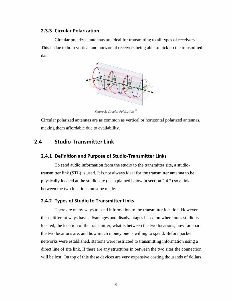
2.3.3 Circular Polarization
Circular polarized antennas are ideal for transmitting to all types of receivers.
This is due to both vertical and horizontal receivers being able to pick up the transmitted
data.
Figure 3: Circular Polariztion [4]
Circular polarized antennas are as common as vertical or horizontal polarized antennas,
making them affordable due to availability.
2.4 Studio-Transmitter Link
2.4.1 Definition and Purpose of Studio-Transmitter Links
To send audio information from the studio to the transmitter site, a studio-
transmitter link (STL) is used. It is not always ideal for the transmitter antenna to be
physically located at the studio site (as explained below in section 2.4.2) so a link
between the two locations must be made.
2.4.2 Types of Studio to Transmitter Links
There are many ways to send information to the transmitter location. However
these different ways have advantages and disadvantages based on where ones studio is
located, the location of the transmitter, what is between the two locations, how far apart
the two locations are, and how much money one is willing to spend. Before packet
networks were established, stations were restricted to transmitting information using a
direct line of site link. If there are any structures in between the two sites the connection
will be lost. On top of this these devices are very expensive costing thousands of dollars.
6
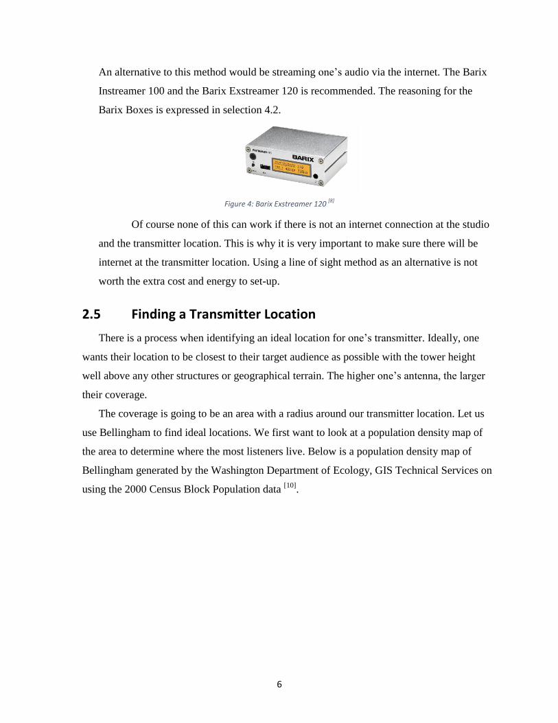
An alternative to this method would be streaming one’s audio via the internet. The Barix
Instreamer 100 and the Barix Exstreamer 120 is recommended. The reasoning for the
Barix Boxes is expressed in selection 4.2.
Figure 4: Barix Exstreamer 120 [8]
Of course none of this can work if there is not an internet connection at the studio
and the transmitter location. This is why it is very important to make sure there will be
internet at the transmitter location. Using a line of sight method as an alternative is not
worth the extra cost and energy to set-up.
2.5 Finding a Transmitter Location
There is a process when identifying an ideal location for one’s transmitter. Ideally, one
wants their location to be closest to their target audience as possible with the tower height
well above any other structures or geographical terrain. The higher one’s antenna, the larger
their coverage.
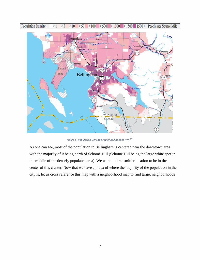
The coverage is going to be an area with a radius around our transmitter location. Let us
use Bellingham to find ideal locations. We first want to look at a population density map of
the area to determine where the most listeners live. Below is a population density map of
Bellingham generated by the Washington Department of Ecology, GIS Technical Services on
using the 2000 Census Block Population data [10]
.
7
Figure 5: Population Density Map of Bellingham, WA
[10]
As one can see, most of the population in Bellingham is centered near the downtown area
with the majority of it being north of Sehome Hill (Sehome Hill being the large white spot in
the middle of the densely populated area). We want out transmitter location to be in the
center of this cluster. Now that we have an idea of where the majority of the population in the
city is, let us cross reference this map with a neighborhood map to find target neighborhoods

8
In figure 6, we can see that our target
neighborhoods include the Lettered Streets,
Sunnyland, York, Sehome, South Hill, Happy
Valley, Samish, Roosevelt, and Puget. All these
locations surround the downtown area where
Make.Shift is located which is a plus. There is
only one more map we need to cross reference
to find our ideal locations, a topographical map
of Bellingham. A topographical map will shows
us the geographical terrain of the city using
contour lines for elevation references.
As stated before we want to find an
elevated location close to the center of the
densest area. With this in mind, the obvious
location would be Sehome Hill. It is higher than
any other structures or geographical terrain, as
shown in figure 7, making it an ideal candidate.
Sehome Hill is also close to all the target
neighborhoods we referenced earlier. Another
good location would be the hill on Yew Street.
Like the Sehome Hill it is high up and near our
target neighborhoods. However, other
constraints, as stated in section 2.2, can play a
role in dismissing these locations.
Figure 6: Bellingham Neighborhood Coverage Map [11]
Figure 7: Bellingham Topographical Map [12]

9
3 Transmitter Locations
3.1 Ideal Locations
In the previous section we showed how some ideal locations for a transmitter site would
be Sehome Hill and Yew Street. We can generate a coverage map to see what our coverage
would be if these location was chosen. We will first observe the Sehome Hill location. This
program, the Radio Coverage Prediction using Longley Rice, takes the geographical terrain
in consideration using the Longley Rice model. Unfortunately it can only generate coverage
maps using either vertical or horizontal
polarized antennas, therefore a vertical
polarization was used for the most accurate
readings for car listeners (as stated in section
2.3.1). The other specifications are shown
below.
The light red color signifies a dBu value between 60 and 75. This is referred to
the minimal usable field strength in an urban environment. Meaning anything outside of
this area may not receive desirable reception. The dark red signifies a dBu value between
75 and 100, where coverage is strong [15]
.
Figure 8: Sehome Hill Coverage Map [13]
Figure 9: Sehome Hill Generate Coverage Data [13]
10
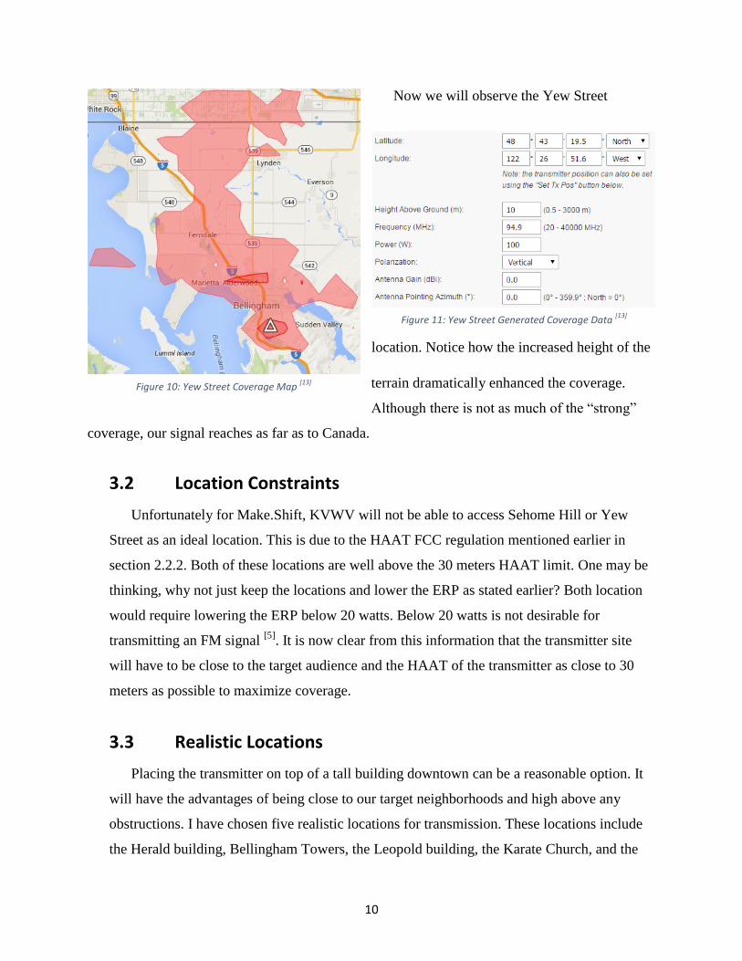
Now we will observe the Yew Street
location. Notice how the increased height of the
terrain dramatically enhanced the coverage.
Although there is not as much of the “strong”
coverage, our signal reaches as far as to Canada.
3.2 Location Constraints
Unfortunately for Make.Shift, KVWV will not be able to access Sehome Hill or Yew
Street as an ideal location. This is due to the HAAT FCC regulation mentioned earlier in
section 2.2.2. Both of these locations are well above the 30 meters HAAT limit. One may be
thinking, why not just keep the locations and lower the ERP as stated earlier? Both location
would require lowering the ERP below 20 watts. Below 20 watts is not desirable for
transmitting an FM signal [5]
. It is now clear from this information that the transmitter site
will have to be close to the target audience and the HAAT of the transmitter as close to 30
meters as possible to maximize coverage.
3.3 Realistic Locations
Placing the transmitter on top of a tall building downtown can be a reasonable option. It
will have the advantages of being close to our target neighborhoods and high above any
obstructions. I have chosen five realistic locations for transmission. These locations include
the Herald building, Bellingham Towers, the Leopold building, the Karate Church, and the
Figure 10: Yew Street Coverage Map [13]
Figure 11: Yew Street Generated Coverage Data [13]
11
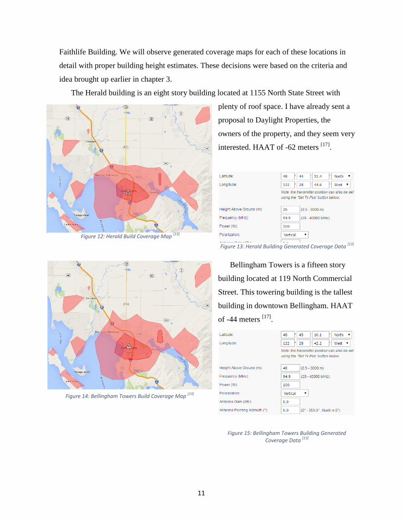
Faithlife Building. We will observe generated coverage maps for each of these locations in
detail with proper building height estimates. These decisions were based on the criteria and
idea brought up earlier in chapter 3.
The Herald building is an eight story building located at 1155 North State Street with
plenty of roof space. I have already sent a
proposal to Daylight Properties, the
owners of the property, and they seem very
interested. HAAT of -62 meters [17]
.
Bellingham Towers is a fifteen story
building located at 119 North Commercial
Street. This towering building is the tallest
building in downtown Bellingham. HAAT
of -44 meters [17]
.
Figure 12: Herald Build Coverage Map [13]
Figure 13: Herald Building Generated Coverage Data [13]
Figure 14: Bellingham Towers Build Coverage Map [13]
Figure 15: Bellingham Towers Building Generated Coverage Data
[13]
12
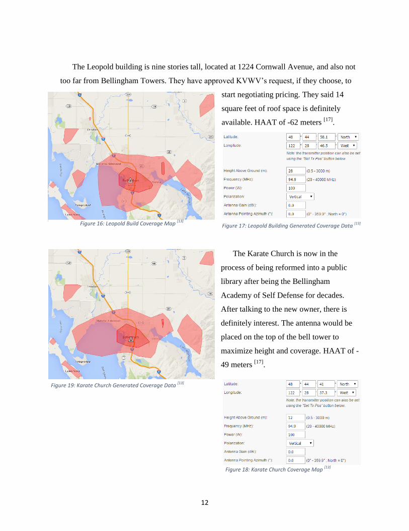
The Leopold building is nine stories tall, located at 1224 Cornwall Avenue, and also not
too far from Bellingham Towers. They have approved KVWV’s request, if they choose, to
start negotiating pricing. They said 14
square feet of roof space is definitely
available. HAAT of -62 meters [17]
.
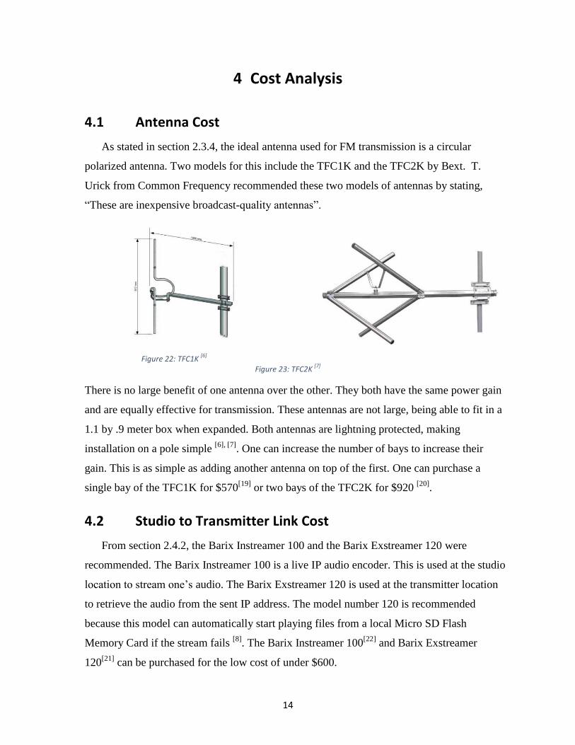
The Karate Church is now in the
process of being reformed into a public
library after being the Bellingham
Academy of Self Defense for decades.
After talking to the new owner, there is
definitely interest. The antenna would be
placed on the top of the bell tower to
maximize height and coverage. HAAT of -
49 meters [17]
.
Figure 16: Leopold Build Coverage Map [13]
Figure 17: Leopold Building Generated Coverage Data [13]
Figure 18: Karate Church Coverage Map [13]
Figure 19: Karate Church Generated Coverage Data [13]

13
The Faithlife building, located at 1313 Commercial St., is a six story structure and is
currently the home of KMRE’s LPFM ratio transmitter site. Communication with KMRE’s
head engineer, M. Gilbert, has already been established. KMRE is currently broadcasting at
102.3 MHz so there should be no issue with interference with KVWV broadcasting a t 94.9
MHz [16]
. HAAT of -69 meters [17]
.
All these maps may look similar but they
have important differences. The height
differences are provided in table 1 below. Although the Karate Church map covers the most
area, it is the only map not to clearly cover both Fairhaven and Happy Valley. The Karate
Church map also covers low populated areas as observed back on the population density
map. Bellingham Towers map is the only map to reach Bakerview Road. All of these things
are good to keep in mind when basing a decision on signal coverage.
Table 1: Realistic Location Information
Location Address Estimated Roof
Height (meters)
HAAT
(meters)
Herald 1155 North State Street,
Bellingham, WA 98225 26 -62
Bellingham
Towers
119 North Commercial Street,
Bellingham, WA 98225 46 -44
Leopold 1224 Cornwall Avenue,
Bellingham, WA 98225 28 -62
Karate Church 519 E Maple Street,
Bellingham, WA 98225 12 -49
Faithlife 1313 Commercial Street,
Bellingham, WA 98225 21 -69
Figure 20: Faithlife Build Coverage Map [13] Figure 21: Faithlife Building Generated Coverage Data
[13]
14
4 Cost Analysis
4.1 Antenna Cost
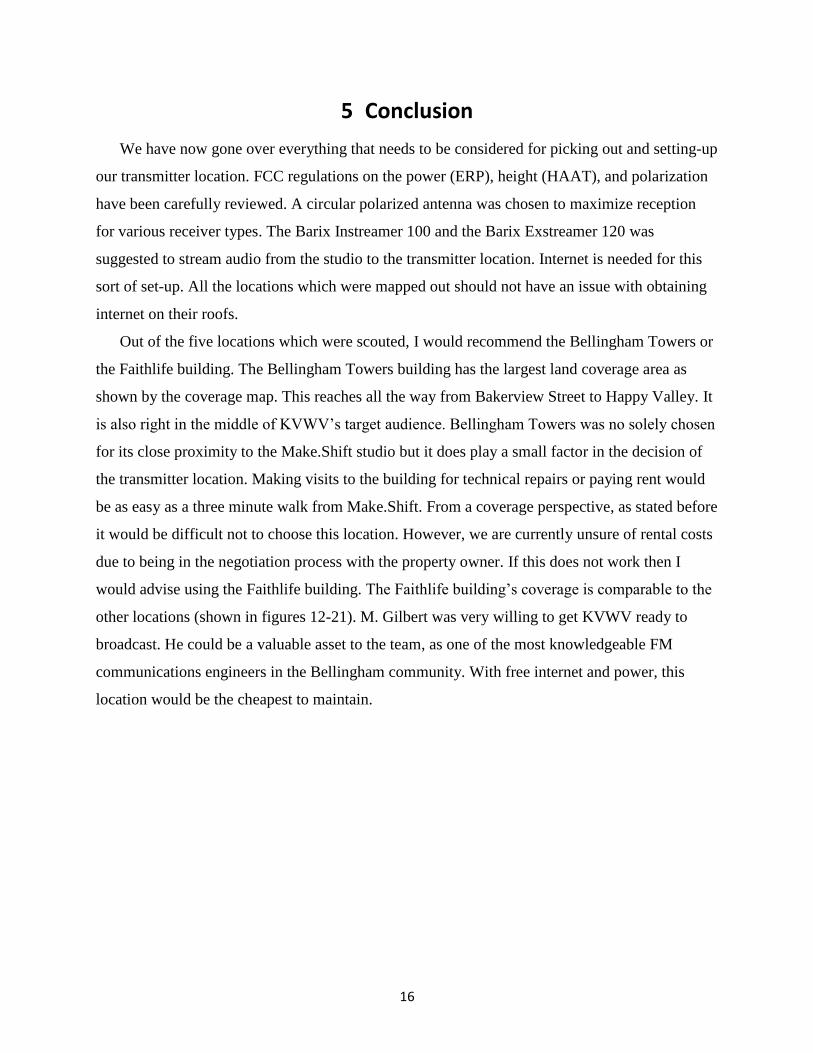
As stated in section 2.3.4, the ideal antenna used for FM transmission is a circular
polarized antenna. Two models for this include the TFC1K and the TFC2K by Bext. T.
Urick from Common Frequency recommended these two models of antennas by stating,
“These are inexpensive broadcast-quality antennas”.
Figure 23: TFC2K [7]
There is no large benefit of one antenna over the other. They both have the same power gain
and are equally effective for transmission. These antennas are not large, being able to fit in a
1.1 by .9 meter box when expanded. Both antennas are lightning protected, making
installation on a pole simple [6], [7]
. One can increase the number of bays to increase their
gain. This is as simple as adding another antenna on top of the first. One can purchase a
single bay of the TFC1K for $570[19]
or two bays of the TFC2K for $920 [20]
.
4.2 Studio to Transmitter Link Cost
From section 2.4.2, the Barix Instreamer 100 and the Barix Exstreamer 120 were
recommended. The Barix Instreamer 100 is a live IP audio encoder. This is used at the studio
location to stream one’s audio. The Barix Exstreamer 120 is used at the transmitter location
to retrieve the audio from the sent IP address. The model number 120 is recommended
because this model can automatically start playing files from a local Micro SD Flash
Memory Card if the stream fails [8]
. The Barix Instreamer 100[22]
and Barix Exstreamer
120[21]
can be purchased for the low cost of under $600.
Figure 22: TFC1K [6]

15
4.3 Transmitter Location Prices
Many of the locations scouted out and mapped are currently under negotiation for rental
fees. This will be resolved later after the logistics between the property managers have sorted
out. The only known cost is for the Faithlife building. M. Gilbert appears willing to share the
KMRE transmitter space for no additional fees. On top of this, he appears willing to let
KVWV use his controller to communicate with the tower from the station. It is important to
differentiate between reoccurring and onetime costs when comparing these different
location’s prices down the line; reoccurring, referring to monthly rental fees, and onetime
costs, referring to an unprepared rooftop for transmission. These cost tradeoffs can overall
dictate the transmitter location.
16
5 Conclusion
We have now gone over everything that needs to be considered for picking out and setting-up
our transmitter location. FCC regulations on the power (ERP), height (HAAT), and polarization
have been carefully reviewed. A circular polarized antenna was chosen to maximize reception
for various receiver types. The Barix Instreamer 100 and the Barix Exstreamer 120 was
suggested to stream audio from the studio to the transmitter location. Internet is needed for this
sort of set-up. All the locations which were mapped out should not have an issue with obtaining
internet on their roofs.
Out of the five locations which were scouted, I would recommend the Bellingham Towers or
the Faithlife building. The Bellingham Towers building has the largest land coverage area as
shown by the coverage map. This reaches all the way from Bakerview Street to Happy Valley. It
is also right in the middle of KVWV’s target audience. Bellingham Towers was no solely chosen
for its close proximity to the Make.Shift studio but it does play a small factor in the decision of
the transmitter location. Making visits to the building for technical repairs or paying rent would
be as easy as a three minute walk from Make.Shift. From a coverage perspective, as stated before
it would be difficult not to choose this location. However, we are currently unsure of rental costs
due to being in the negotiation process with the property owner. If this does not work then I
would advise using the Faithlife building. The Faithlife building’s coverage is comparable to the
other locations (shown in figures 12-21). M. Gilbert was very willing to get KVWV ready to
broadcast. He could be a valuable asset to the team, as one of the most knowledgeable FM
communications engineers in the Bellingham community. With free internet and power, this
location would be the cheapest to maintain.
17
References
[1] Makeshiftproject.com, 'Our Mission & History | Make.Shift', 2015. [Online]. Available:
http://makeshiftproject.com/about-us/our-mission/. [Accessed: 08- Mar- 2015].
[2] Air-stream.org.au, 'Antenna Polarization', 2015. [Online]. Available: http://www.air-
stream.org.au/technical-references/antenna-polarisation. [Accessed: 08- Mar- 2015].
[3] Iris.nyit.edu, 'VERTICAL POLARIZATION AND FM TRANSMITTER ANTENNA
PERFORMANCE OPTIMIZATION', 2015. [Online]. Available:
http://iris.nyit.edu/~sblank/VPforFM.htm. [Accessed: 08- Mar- 2015].
[4] Upload.wikimedia.org, 2015. [Online]. Available:
http://upload.wikimedia.org/wikipedia/commons/thumb/7/77/Circular.Polarization.Circularl
y.Polarized.Light_With.Components_Right.Handed.svg/440px-
Circular.Polarization.Circularly.Polarized.Light_With.Components_Right.Handed.svg.png.
[Accessed: 08- Mar- 2015].
[5] T. Urick, private communication, 2015.
[6] www.bext.com, 'TFC1K', 2015. [Online]. Available: http://www.bext.com/pdf/P047-
TFC1K.pdf. [Accessed: 08- Mar- 2015].
[7] www.bext.com, 'TFC2K', 2015. [Online]. Available: http://www.bext.com/pdf/P046-
TFC2K.pdf. [Accessed: 08- Mar- 2015].
[8] Ip-audio.com, 'Barix Exstreamer 120 | Barix Exstreamer | Exstreamer | Barix IP-Audio | IP
Audio | Audio over IP | Audio over Ethernet | IP Paging | IP Ethernet Internet Intercom |
VoIP Intercom | Audio over Internet | Audio over TCP/IP', 2015. [Online]. Available:
http://www.ip-audio.com/audio/exstreamer120.php. [Accessed: 08- Mar- 2015].
[9] www.prometheusradio.org, 2015. [Online]. Available:
http://prometheusradio.org/sites/default/files/transmission_toolkit.pdf. [Accessed: 08- Mar-
2015].
[10] wria1project.whatcomcounty.org, 'Bellingham, WA Population Density Map', 2015.

18
[Online]. Available:
http://wria1project.whatcomcounty.org/uploads/PDF/Maps/ecology_popdensity.pdf.
[Accessed: 08- Mar- 2015].
[11] Cob.org, 'Bellingham, WA Neighborhood Map', 2015. [Online]. Available:
http://www.cob.org/documents/gis/maps/COB_Nhoodmap.jpg. [Accessed: 08- Mar- 2015].
[12] Google.com, 'Google Maps', 2015. [Online]. Available: https://www.google.com/maps.
[Accessed: 08- Mar- 2015].
[13] M. Lussier, 'Coverage Prediction', Lrcov.crc.ca, 2015. [Online]. Available:
http://lrcov.crc.ca/main/index.php. [Accessed: 08- Mar- 2015].
[14] Ecfr.gov, 'Code of Federal Regulations', 2015. [Online]. Available: http://www.ecfr.gov/cgi-
bin/text-idx?node=sp47.4.73.g&rgn=div6. [Accessed: 08- Mar- 2015].
[15] 'Defining Signal Strength', 2015. [Online]. Available:
http://www.wrap.se/files/product/presentations/amman/wrap1801_AnalogueSoundTV.pdf.
[Accessed: 08- Mar- 2015].
[16] M. Gilbert, private communication, 2015.
[17] Fcc.gov, 'Antenna Height above Average Terrain (HAAT) Calculator', 2015. [Online].
Available: http://www.fcc.gov/encyclopedia/antenna-height-above-average-terrain-haat-
calculator. [Accessed: 08- Mar- 2015].
[18] Daftlogic.com, 'Google Maps Find Altitude', 2015. [Online]. Available:
http://www.daftlogic.com/sandbox-google-maps-find-altitude.htm. [Accessed: 08- Mar-
2015].
[19] Scmsinc.com, 'BEXT TFC1K Price', 2015. [Online]. Available:
https://www.scmsinc.com/shop-item/transmission-products-antennas/tfc1k-n-bext-tfc1k-n-
circularly-polarized-omni-directional-fm-antenna-87-5-108-mhz/. [Accessed: 08- Mar-
2015].
[20] Scmsinc.com, 'BEXT TFC2K Price', 2015. [Online]. Available:

https://www.scmsinc.com/shop-item/item/tfc2k-n-bext-tfc2k-n-circularly-polarized-omni-
directional-fm-antenna-87-5-108-mhz/. [Accessed: 08- Mar- 2015].
[21] 1 PC Network Inc, 'Barix Exstreamer 120 IP Audio Stream Decoder Price', 2015. [Online].
Available: http://shop.1pcn.com/barix-exstreamer-120-ip-audio-stream-decoder-sku-barix-
exst-120-msrp-265-00-1/. [Accessed: 08- Mar- 2015].
[22] Bswusa.com, 'Barix Instreamer Price', 2015. [Online]. Available:
http://www.bswusa.com/Codecs-Barix-Instreamer-
P8850.aspx?gclid=CMD09bCpl8QCFciGfgodEw8Ahw. [Accessed: 08- Mar- 2015].
[23] Stavisky, Alan G., Robert K. Avery, and Helena Vanhala. "From Class D to LPFM: The
High-Powered Politics of Low-Power Radio." Journalism & Mass Communication
Quarterly 78 (2001): 340–54.
[24] Cimms.ou.edu, 'Polarimetric Radar Page', 2015. [Online]. Available:
http://cimms.ou.edu/~schuur/radar.html. [Accessed: 08- Mar- 2015].
[25] Joseph H. Reisert, ‘Antenna Polarization’, 2015. [Online]. Available:
http://www.astronwireless.com/topic-archives-antennas-polarization.asp. [Accessed: 19-
Mar- 2015].
[26] M. [email protected], '-10dBV and +4dBu voltage levels',
Harmoniccycle.com, 2015. [Online]. Available: http://www.harmoniccycle.com/hc/music-
26-+4dBu-10dBV.htm. [Accessed: 13- Jun- 2015].