Pennsylvania Stormwater Best Management Practices Manual ...
A Stormwater Master Plan For The University of PennsylvaniaFinding Opportunities for Sustainable Stormwater Management
March 2013
prepared by:
Duffield AssociatesLRSLA Studio, Inc.

2 A Stormwater Master Plan For the University of Pennsylvania
33
CONTENTS
Section 1 EXECUTIVE SUMMARY 6
Section 2 STORMWATER RUN-OFF FROM TODAY’S CAMPUS 20
Section 3 STORMWATER MANAGEMENT ON TODAY’S CAMPUS 30
Section 4 POTENTIAL STORMWATER MANAGEMENT PRACTICES FOR FUTURE PROJECTS 56
Section 5 FINDING SUSTAINABLE STORMWATER MANAGEMENT OPPORTUNITIES 70
Section 6 STORMWATER MANAGEMENT COSTS AND PWD FEES 116
Section 7 OPERATIONS AND MAINTENANCE CONSIDERATIONS 124
Section 8 LEGISLATION ISSUES AND FUNDING OPPORTUNITIES 134
Section 9 RECOMMENDATIONS 140
Section 10 APPENDICES 148
A. Representative Stormwater Management Details
B. Stormwater Management Model
C. References
D. Acknowledgements
A Stormwater Master Plan For The University of PennsylvaniaFinding Opportunities for Sustainable Stormwater Management

4 A Stormwater Master Plan For the University of Pennsylvania

55
Section 1 EXECUTIVE SUMMARY
Section 2 STORMWATER RUN-OFF FROM TODAY’S CAMPUS
Section 3 STORMWATER MANAGEMENT ON TODAY’S CAMPUS
Section 4 POTENTIAL STORMWATER MANAGEMENT PRACTICES FOR FUTURE PROJECTS
Section 5 FINDING SUSTAINABLE STORMWATER MANAGEMENT OPPORTUNITIES
Section 6 STORMWATER MANAGEMENT COSTS AND PWD FEES
Section 7 OPERATIONS AND MAINTENANCE CONSIDERATIONS
Section 8 LEGISLATION ISSUES AND FUNDING OPPORTUNITIES
Section 9 RECOMMENDATIONS
Section 10 APPENDICES
A. Representative Stormwater Management Details
B. Stormwater Management Model
C. References
D. Acknowledgements
6 A Stormwater Master Plan For the University of Pennsylvania
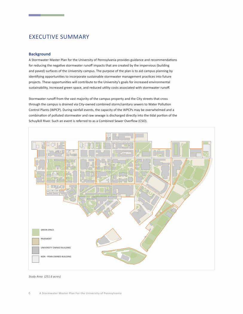
BackgroundA Stormwater Master Plan for the University of Pennsylvania provides guidance and recommendations
for reducing the negative stormwater runoff impacts that are created by the impervious (building
and paved) surfaces of the University campus. The purpose of the plan is to aid campus planning by
identifying opportunities to incorporate sustainable stormwater management practices into future
projects. These opportunities will contribute to the University’s goals for increased environmental
sustainability, increased green space, and reduced utility costs associated with stormwater runoff.
Stormwater runoff from the vast majority of the campus property and the City streets that cross
through the campus is drained via City-owned combined storm/sanitary sewers to Water Pollution
Control Plants (WPCP). During rainfall events, the capacity of the WPCPs may be overwhelmed and a
combination of polluted stormwater and raw sewage is discharged directly into the tidal portion of the
Schuylkill River. Such an event is referred to as a Combined Sewer Overflow (CSO).
EXECUTIVE SUMMARY
Study Area (251.6 acres)
WALL
GREEN SPACE
PAVEMENT
UNIVERSITY OWNED BUILDING
NON - PENN OWNED BUILDING

Section 1 EXECUTIVE SUMMARY 7
Stormwater runoff from Penn’s campus is regulated by the Philadelphia Water Department (PWD).
In addition to providing drinking water for the City of Philadelphia, one of PWD’s primary goals is to
reduce the frequency of Combined Sewer Overflows, for which the City is fined by the Pennsylvania
Department of Environmental Protection (PADEP). In 2006, PWD enacted Stormwater Management
Regulations that require private and public land development and redevelopment projects to provide
stormwater management to meet specific criteria.
In June 2011, PWD signed a Consent Order and Agreement with the PADEP for implementation of
their landmark 25-year control plan titled Green City, Clean Waters. One of the performance standards
included within this plan involves the development of Green Stormwater Infrastructure (GSI). GSI
"disconnects" impervious surfaces from the sewer system by directing stormwater runoff through
green stormwater management practices (SMPs) such as green roofs, porous pavement, and vegetated
bioretention areas. GSI reduces the volume of stormwater runoff from impervious surfaces by utilizing
processes such as infiltration, evaporation, transpiration, and reuse. Incorporating these processes
within an urbanized environment reduces flow to the combined sewer system, thereby aiding in the
reduction of CSOs.
To fund the implementation of the control plan, PWD instituted a monthly parcel-based stormwater
fee program in 2009 for all non-residential properties within the City limits. Prior to 2009, properties
were charged a sewer fee based on the size of the water meter(s) serving the property. This meter-
based method did not account for the impact of a property’s impervious area and its contribution to
the CSO problem. For example, a high-rise apartment building with a small footprint area generates
comparatively little stormwater runoff but has a large water meter to supply the numerous dwelling
units, and thus was paying a large sewer fee under the previous system. Conversely, a large commercial
parking area with no water meter generates a significant runoff volume, yet paid no sewer fee under
the meter-based system.
To provide a more equitable distribution of sewer fees that recognizes the significant impact of
impervious surfaces on the CSO problem, PWD instituted the parcel-based fee structure, to be fully
phased in by 2014. Under this program, PWD has determined the parcel area and its impervious
cover for each property in the City using aerial photography and City tax record information. Fees are
assessed at a rate per 500 square feet of impervious area and parcel area. For properties with existing
impervious areas, owners can reduce their stormwater fee by voluntarily implementing stormwater
management controls that meet PWD requirements and then apply for fee credits. Newly constructed
projects that incorporate required stormwater management facilities must also apply for fee credits for
the new systems.
Guiding Penn’s overall environmental sustainability initiatives, Penn President Dr. Amy Gutmann signed
the American College and University President’s Climate Commitment in 2007. Penn’s Climate Action
Plan adopted in 2009, includes a number of efforts to improve the environmental performance of
the physical campus. These initiatives include: the goal to add 20 percent more green space to Penn’s
8 A Stormwater Master Plan For the University of Pennsylvania
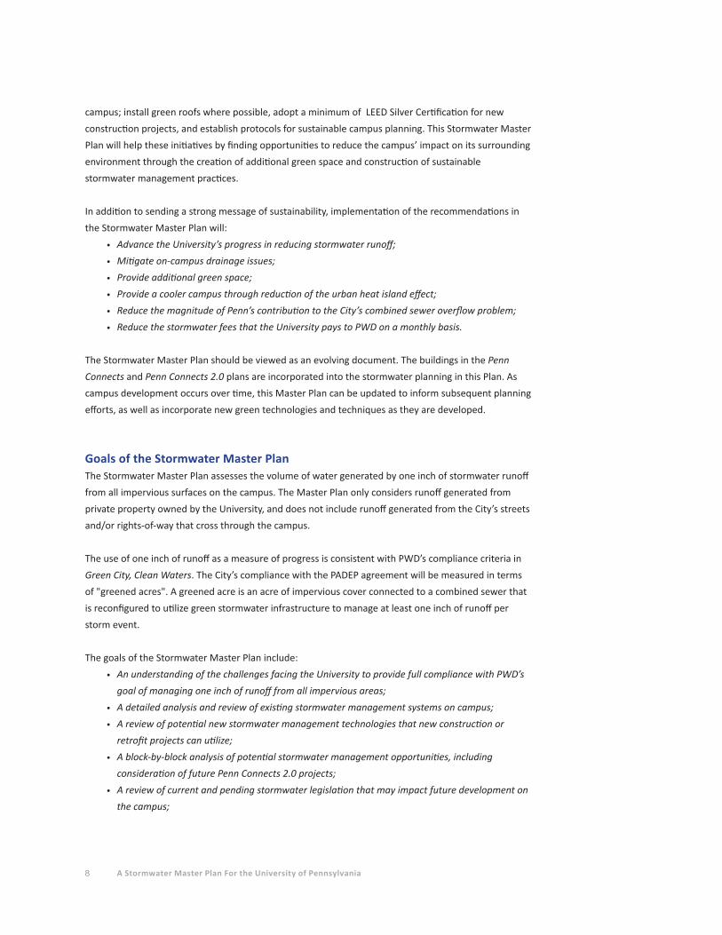
campus; install green roofs where possible, adopt a minimum of LEED Silver Certification for new
construction projects, and establish protocols for sustainable campus planning. This Stormwater Master
Plan will help these initiatives by finding opportunities to reduce the campus’ impact on its surrounding
environment through the creation of additional green space and construction of sustainable
stormwater management practices.
In addition to sending a strong message of sustainability, implementation of the recommendations in
the Stormwater Master Plan will:
• Advance the University’s progress in reducing stormwater runoff;
• Mitigate on-campus drainage issues;
• Provide additional green space;
• Provide a cooler campus through reduction of the urban heat island effect;
• Reduce the magnitude of Penn’s contribution to the City’s combined sewer overflow problem;
• Reduce the stormwater fees that the University pays to PWD on a monthly basis.
The Stormwater Master Plan should be viewed as an evolving document. The buildings in the Penn
Connects and Penn Connects 2.0 plans are incorporated into the stormwater planning in this Plan. As
campus development occurs over time, this Master Plan can be updated to inform subsequent planning
efforts, as well as incorporate new green technologies and techniques as they are developed.
Goals of the Stormwater Master PlanThe Stormwater Master Plan assesses the volume of water generated by one inch of stormwater runoff
from all impervious surfaces on the campus. The Master Plan only considers runoff generated from
private property owned by the University, and does not include runoff generated from the City’s streets
and/or rights-of-way that cross through the campus.
The use of one inch of runoff as a measure of progress is consistent with PWD’s compliance criteria in
Green City, Clean Waters. The City’s compliance with the PADEP agreement will be measured in terms
of "greened acres". A greened acre is an acre of impervious cover connected to a combined sewer that
is reconfigured to utilize green stormwater infrastructure to manage at least one inch of runoff per
storm event.
The goals of the Stormwater Master Plan include:
• An understanding of the challenges facing the University to provide full compliance with PWD’s
goal of managing one inch of runoff from all impervious areas;
• A detailed analysis and review of existing stormwater management systems on campus;
• A review of potential new stormwater management technologies that new construction or
retrofit projects can utilize;
• A block-by-block analysis of potential stormwater management opportunities, including
consideration of future Penn Connects 2.0 projects;
• A review of current and pending stormwater legislation that may impact future development on
the campus;
Section 1 EXECUTIVE SUMMARY 9
• A review of current grant or funding opportunities to support development of stormwater
management practices;
• Initial development of a campus stormwater model to track the construction and removal
of impervious area, and to account for the stormwater volume-reducing effects of newly
constructed stormwater management practices;
• Development of representative details for green stormwater management practices for use by
the University and its design consultants;
• Development of an Operations and Maintenance Manual for existing stormwater management
practices on campus, to provide instructions, recommendations and scheduling for maintaining
the various systems, and to facilitate the development of a maintenance log for each practice, as
required by PWD.
The remainder of the Executive Summary includes a summation of the content of each section of the
Master Plan. The full sections should be referenced for more detailed discussions of the topics.
Section 2 - Stormwater Runoff from Today’s CampusStormwater runoff from the vast majority of the campus is not managed by facilities that reduce the
rate or volume of runoff. Most campus buildings have their roof downspouts directly connected to the
City’s combined sewer system via underground pipes. Impervious surfaces at ground level (e.g., parking
areas, walkways) typically drain to storm inlets located on campus property or in the City streets that
are also directly connected to the public sewer system.
In 2006, the Philadelphia Water Department (PWD) enacted Stormwater Management Regulations as
per the Philadelphia Code, Chapter 14-1603.1.6.c.1. These regulations, summarized in Section 2, aim to
at least partially restore the natural hydrologic cycle to the City’s land by requiring the infiltration of the
first inch of runoff from impervious surfaces.
One of the University’s primary goals for the Stormwater Master Plan is to assess the feasibility of
managing one inch of runoff from all campus impervious surfaces. Another goal of the plan is to seek
campus-wide solutions to stormwater management, rather than continue with the current project-by-
project approach.
To get an overall understanding of the magnitude of the effort required to manage one inch of runoff
from all University impervious areas, all impervious surface areas within the plan’s study area were
inventoried and the volume of water generated by one inch of runoff from those surfaces was
calculated.
The inventory areas (rounded to the nearest 1000 square feet) are as follows:
• Total Campus Study Area (not including City street rights-of-way): 10,958,000 sf (251.6 acres)
• Total Roof Area: 4,051,000 sf (93.0 acres)
• Total Ground-Level Impervious Area: 3,787,000 sf (86.9 acres)
• Total Impervious Area: 7,838,000 sf (179.9 acres)
10 A Stormwater Master Plan For the University of Pennsylvania
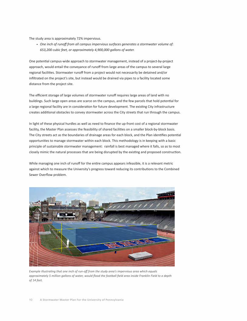
The study area is approximately 72% impervious.
• One inch of runoff from all campus impervious surfaces generates a stormwater volume of:
653,200 cubic feet, or approximately 4,900,000 gallons of water.
One potential campus-wide approach to stormwater management, instead of a project-by-project
approach, would entail the conveyance of runoff from large areas of the campus to several large
regional facilities. Stormwater runoff from a project would not necessarily be detained and/or
infiltrated on the project’s site, but instead would be drained via pipes to a facility located some
distance from the project site.
The efficient storage of large volumes of stormwater runoff requires large areas of land with no
buildings. Such large open areas are scarce on the campus, and the few parcels that hold potential for
a large regional facility are in consideration for future development. The existing City infrastructure
creates additional obstacles to convey stormwater across the City streets that run through the campus.
In light of these physical hurdles as well as need to finance the up-front cost of a regional stormwater
facility, the Master Plan assesses the feasibility of shared facilities on a smaller block-by-block basis.
The City streets act as the boundaries of drainage areas for each block, and the Plan identifies potential
opportunities to manage stormwater within each block. This methodology is in keeping with a basic
principle of sustainable stormwater management: rainfall is best managed where it falls, so as to most
closely mimic the natural processes that are being disrupted by the existing and proposed construction.
While managing one inch of runoff for the entire campus appears infeasible, it is a relevant metric
against which to measure the University’s progress toward reducing its contributions to the Combined
Sewer Overflow problem.
Example illustrating that one inch of run-off from the study area's impervious area which equals approximately 5 million gallons of water, would flood the football field area inside Franklin Field to a depth of 14 feet.
14'
Section 1 EXECUTIVE SUMMARY 11
Section 3 - Stormwater Management on Today’s CampusSince the adoption of the PWD Stormwater Regulations in 2006, Penn has completed (or has under
construction) more than a dozen projects that incorporate stormwater management facilities.
These projects include green roofs, porous pavement, and bioretention areas, as well as subsurface
infiltration/detention systems and water quality management devices.
PROJECT APPROVAL DATE
• George Weiss Pavilion February 4, 2009
• Music Building February 28, 2009
• Cira South Garage (3rd Party Development) March 29, 2009
• Class of '62 Walkway (37th Street) May 14, 2009
• Woodland Walk July 14, 2009
• Penn Park April 29, 2010
• Golkin Law School May 7, 2010
• Singh Nanotechnology Center February 23, 2011 (under construction)
• Locust Walk Reconstruction May 2, 2011
• Shoemaker Green July 27, 2011
A variety of stormwater management practices were utilized in the design of these projects, as
noted below:
STORMWATER MANAGEMENT PRACTICE IMPERVIOUS AREA MANAGED
• Green Roofs 15,511 sf
• Porous Pavement 49,773 sf +
• Bioretention Area 140,176 sf +
• Subsurface Infiltration 13,437 sf
• Subsurface Detention 467,440 sf
• Disconnected Roof 3,982 sf
• Disconnected Pavement 26,777 sf
• Tree Credits 46,745 sf +
• Total Impervious Area Managed 763,841 sf (17.5 acres)
Section 3 includes summaries of the projects and their stormwater management practices, along
with site maps for each project showing individual SMP locations. Additional projects in design or
construction (or recently constructed) that will incorporate stormwater management practices include
Spruce Street Plaza, Hutchinson Gym Renovation, Steinberg-Deitrich Hall Addition, the new College
House, Neural-Behavioral Sciences Building, Cira South Chestnut Apartments, and Walnut Street
Streetscape Improvements.
Section 4 - Potential Stormwater Management Practices for Future ProjectsStormwater management technology continues to evolve as a result of increased regulatory
requirements and a desire to create sustainable solutions that attempt to restore the natural hydrologic
cycle by mimicking natural processes such as infiltration and bioretention. Penn has already embraced
12 A Stormwater Master Plan For the University of Pennsylvania
some of these storm water management practices (SMP’s) in the form of green roofs, bio-retention
areas, and porous pavements. Section 4 identifies a number of innovative practices which the
University and its consultants may want to consider applying as stormwater management strategies
for future development and redevelopment projects.
These contemporary practices include utilizing modular green building components, stormwater
capture and reuse systems, porous pavement treatments, green streetscapes, and bio-infiltration
systems.
Section 5 - Finding Sustainable Stormwater Management OpportunitiesSection 5 provides a block-by-block analysis of the campus, identifying potential opportunities for
stormwater retrofitting of existing buildings with green roofs; retrofitting of existing paved areas
with porous pavements; shared stormwater management facilities; and possible options for future
construction of facilities described in the Penn Connects 2.0 plan. The intent of this distributed
approach is to manage rainfall where it falls, rather than concentrating and conveying it via pipes to
other locations.
A procedural step-by-step framework is provided for utilizing the block-by-block diagrams in the
stormwater planning process. For new construction, these steps include:
• Identify project requirements with a conceptual site plan;
• Review planned construction on adjoining blocks;
• Identify existing utilities in the streets surrounding the proposed construction;
• Consider "banking/trading" options (defined in Section 5);
• Identify existing utilities within the block of the proposed construction;
• Identify shared facility options;
• Identify green roof potential for new and existing buildings;
• Conduct infiltration testing to determine feasibility of infiltrating stormwater
management systems;
• Prepare a conceptual stormwater design.
Additional recommendations are provided for using the block-by-block diagrams in the evaluation of
potential retrofit and green streets projects.
Section 6 - Stormwater Management and Construction Costs and PWD FeesTypical construction costs for the various sustainable stormwater management practices are provided.
Ultimately, the PWD Stormwater Regulations will dictate what level of stormwater management is
required for a given project. The site design will determine what practices are available to provide
the required regulatory compliance. Then site constraints will determine which of those practices will
work on the site. These factors will determine the construction costs to be considered when evaluating
stormwater management practices for a given project.
The PWD stormwater fee structure is reviewed in detail. The impact of the fee on the return on

Section 1 EXECUTIVE SUMMARY 13
investment period for stormwater retrofits is described. In some cases, the fee structure does not
provide a realistic incentive to invest in green stormwater practices.
A discussion of cost sharing for shared stormwater management facilities is provided. The most
feasible approach appears to be the sharing of costs based on the volume of stormwater management
for each project connected to a shared system.
Section 7 - Operations and Maintenance ConsiderationsUnder the PWD Stormwater Regulations, property owners must sign Operations and Maintenance
(O&M) Agreements stipulating that the owner is responsible for the proper functioning and
performance monitoring of the approved stormwater management practices. If the facilities are
allowed to deteriorate to the point that they no longer provide their approved design function,
the owner could be forced to completely reconstruct the facilities to return the site’s stormwater
management to compliance with PWD’s regulations.
Example of typical block-by-block diagram
34 th
STR
EET
CHESTNUT STREET
Gittis Hall
Golkin Hall
Silverman HallEnglish House Tanenbaum Hall
Kings Court
36 th
STR
EET
WALNUT STREET
SANSOM STREET
Sansom Row
133 S. 36th
3401 Walnut Street
Moravian Street
A
A
A
A
GO
AT
Franklin Buiding Annex
Franklin Buiding
POTENTIAL GREEN ROOF CONVERSION • Kings Court 12,700 sf• Tanenbaum Hall 16,600 sf• Gittis Hall 11,500 sf• 133 S. 36th 6,420 sf• Franklin Annex 19,500 sf• 3401 Walnut 43,930 sf
EXISTING GREEN ROOF • Golkin Hall 7,210 sf• English House
EXISTING POROUS PAVEMENT• Golkin Hall 7,420 sf
POTENTIAL BIORETENTION AREA• In existing grass area to manage roofs.
EXISTING GREEN SPACE
EXISTING TREE • Potential Credit
EXISTING PAVEMENT • Potential Disconnection
PENN CONNECTS/POTENTIAL DEVELOPMENT• Franklin Building Redevelopment• Potential green roof
UNIVERSITY OWNED BUILDING• No green roof proposed
• Buildings less feasible for green roof retrofit
A
Franklin Building Revevelopment
Proposed Mixed-use
Parcel

14 A Stormwater Master Plan For the University of Pennsylvania
Perhaps the most significant shift in thinking required in the development of green stormwater
management is the acceptance that considerable funds must be allocated to the long-term
maintenance and monitoring of green stormwater management practices. The systems must be
maintained and repaired as needed to ensure that filtration and infiltration continue to perform
as intended.
Determining a budget for maintenance is best approached with an understanding that the costs of
facility maintenance should be viewed as protecting the investment in the original construction of
the stormwater practices as well as protecting the University from liability issues. Additionally, the
University’s goal of promoting sustainability on campus should support the commitment to diligent
maintenance in order to reduce the University’s impact on the environment.
The University must evaluate whether to monitor PWD requirements with its internal facilities staff
or by contracting the work to a company that specializes in stormwater system maintenance. As
part of this Master Plan, cost estimates from outside services were obtained for several University
projects. The University will compare these contracted costs to their expenditures using University
staff and equipment for the required maintenance. This section also discusses possible changes in
the University’s landscape maintenance practices which may reduce stormwater facility maintenance
requirements.
A separate Operations and Maintenance Manual was prepared as part of this Master Plan. The Manual
includes the PWD Operations and Maintenance Agreements for the recently constructed projects, as
well as recommended guidelines for maintenance of the various stormwater management practices.
Section 8 - Legislation Issues and Funding OpportunitiesCurrent legislation is discussed, as well as potential impending regulation changes which may impact
future development on the Penn campus. Potential sources of funding for stormwater management
improvements are also reviewed.
Perhaps the most significant potential change to the current regulations is PWD’s consideration
of lowering the earth disturbance area threshold that triggers compliance with the stormwater
regulations. According to Section 1.2.4.2 of the Long Term Control Plan Update (LTCPU) document,
"PWD is considering modifications to the current regulations, including to lower the threshold of
disturbance that triggers the regulations for compliance with the regulations from the current level of
15,000 square feet to a level of disturbance of 5,000 square feet." For reference, a typical parking area
containing approximately 18 parking spaces with a central two-way drive aisle occupies approximately
5,000 square feet.
The lowering of the earth disturbance threshold to 5,000 square feet would have broader implications
for future campus development. With this lower threshold, smaller building additions, parking
lot expansions, or pedestrian area restorations could trigger the requirement to comply with the
stormwater regulations, and add project costs.

Section 1 EXECUTIVE SUMMARY 15
Changes to State and Federal regulations are less well defined. According to the U.S. Environmental
Protection Agency’s website, "EPA intends to propose a rule to strengthen the national stormwater
management program by June 10, 2013 and complete a final action by December 10, 2014." Until EPA
provides concise information on what regulatory changes may be coming to Pennsylvania, it is not
possible to determine what impacts the changes may have on future campus development.
Potential funding opportunities for the construction of green stormwater management practices are
reviewed in this section. The Philadelphia Water Department (PWD) and the Philadelphia Industrial
Development Corporation (PIDC) created the Stormwater Management Incentive Program (SMIP) to
offer grant assistance to non-residential PWD customers. Funding provided by the program provides
incentive for property owners to implement green stormwater management practices that will reduce
their monthly PWD stormwater fees. The first round of grant applications ended on March 31, 2012.
Based on discussions with PIDC and PWD, the agencies intend to continue the program for several years,
depending on its success and the availability of funding.
Section 9 – RecommendationsThe Stormwater Master Plan is intended to serve as a planning tool to identify opportunities for
increasing sustainability during new campus development or redevelopment projects. Stormwater
planning should be incorporated early into the planning process for all new projects.
This section provides recommendations for integrating stormwater planning into the land use planning
process, as well as for advancing the University’s goal to increase the management of stormwater
runoff from currently unmanaged existing sites. The recommendations are more fully discussed in the
complete section.
Primary Stormwater Planning Recommendations1. Pursue increased stormwater management on a block-by-block approach rather than a
campus-wide approach.
2. Redevelopment of existing impervious sites on campus should strive to provide a 20 percent
reduction in impervious areas compared to pre-development conditions.
3. The primary stormwater management goal of all construction projects should be the
management of the first one inch of runoff from impervious surfaces for new and retrofit
projects.
4. The large projects envisioned in the Penn Connects 2.0 plan may provide significant
opportunities for attaining meaningful stromwater management practices.
5. Consider increasing the storage capacity of stormwater management facilities on new projects
to accommodate the future rainleader connection of adjacent existing buildings and runoff
from impervious areas which are currently unmanaged.
6. Consider stormwater management retrofits of existing buildings and impervious areas as part
of the University’s renewal and reinvestment program.
7. Consider investing in green roofs as a signature feature on Penn’s campus. Green roofs often
provide cost savings by reducing ground-level stormwater management facilities, increasing

16 A Stormwater Master Plan For the University of Pennsylvania
life cycles of roof membranes, and reducing heating and cooling costs.
8. Evaluate the feasibility and maintenance costs of installing porous pavements for all new
impervious areas as a way to reduce the need for subsurface infiltration/detention systems.
9. Continue the current policy to remove surface parking areas by more effective use of
perimeter parking structures. Less pavement equals less stormwater runoff.
10. Establish a diligent Operations and Maintenance Program to protect the investment in the
stormwater management practices already constructed and planned. As with any engineered
system, periodic preventive maintenance will always be more cost-effective than delaying
maintenance until the system exhibits signs of impending failure.
Short-term Recommendations (0 to 6 Months)
1. The University should obtain and evaluate cost proposals for stormwater facility maintenance
from several companies specializing in these operations. Using a private company may be cost
effective by reducing the training and equipment costs required to implement an internally
managed successful O&M program.
2. Verify that all applications have been submitted to and approved by PWD for obtaining the
stormwater fee credits for the projects constructed since 2006.
3. Review the PWD billing information for all University properties to ensure the University is
paying the correct fees.
4. Continue to meet regularly with PWD to discuss ongoing stormwater planning issues on
campus. Additional potential topics of discussion are suggested in the complete Section 9.
Mid-term Recommendations (6 Months to 5 Years)
1. Using the block-by-block diagrams in Section 5 as a guide, further evaluate the cost/benefit of
green roof retrofits on existing buildings.
2. Assess the potential to disconnect existing roof downspouts from a direct connection to the
City’s combined sewer system and redirect them to new subsurface infiltration/detention
facilities.
3. As new projects are planned and designed over the next 5 years, the following stormwater
practices should be considered as part of the overall stormwater management strategy for
each project: capture and reuse of stormwater rainfall, conversion of turf grass areas to
bioretention areas and meadow areas, and planting of new trees.
4. Gather the construction cost data for the stormwater management practices built as part of
the projects constructed since 2006. An analysis of construction costs for these projects may
provide valuable cost-benefit information for other projects.
5. Consider mapping all non-University utilities located in the City streets to assist with
evaluating potential cross-street stormwater transfers and green streets projects.
6. Specify the use of double-ring infiltrometers for all infiltration testing. This is the methodology
preferred by PWD and PADEP and, should provide the most reliable information for infiltration
system design.
Section 1 EXECUTIVE SUMMARY 17
Long-term Recommendations (Beyond 5 Years)
1. Explore potential "green street" development on campus in conjunction with PWD and the
City’s Streets Department. Liability issues associated with directing potentially contaminated
stormwater runoff from public streets onto the University’s private property are discussed in
Section 5.
2. Promote stormwater research in academic programs. This research could be conducted in
conjunction with PWD, PADEP, or other local, state, or federal agencies.
3. Consider development of a monitoring program (in partnership with its academic programs)
to test installed green stormwater management practices for performance evaluation. This
program would undertake more extensive monitoring than that required by PWD. Collected
data could be used to evaluate critical design criteria for various stormwater practices.
For example, detailed collection and analysis of rainfall data and resultant use of captured
rainwater for irrigation water at Penn Park could improve the design of other potential
capture/reuse systems on campus.
Additional guidelines are provided for the further evaluation of potential green roof retrofitting of
existing buildings, including structural considerations.
It is anticipated that the information presented in the Stormwater Master Plan will evolve over
time as the University’s plans for future development unfolds, as new stormwater management
technologies and techniques are created, and with the adoption of new stormwater regulations at all
levels of government. The Master Plan should be revisited in five years to respond to the University’s
development and to maximize the use of emerging state-of-the-art design methodologies for
sustainable stormwater management.

18 A Stormwater Master Plan For the University of Pennsylvania
Section 1 EXECUTIVE SUMMARY 19
Section 1 EXECUTIVE SUMMARY
Section 2 STORMWATER RUN-OFF FROM TODAY’S CAMPUS
Section 3 STORMWATER MANAGEMENT ON TODAY’S CAMPUS
Section 4 POTENTIAL STORMWATER MANAGEMENT PRACTICES FOR FUTURE PROJECTS
Section 5 FINDING SUSTAINABLE STORMWATER MANAGEMENT OPPORTUNITIES
Section 6 STORMWATER MANAGEMENT COSTS AND PWD FEES
Section 7 OPERATIONS AND MAINTENANCE CONSIDERATIONS
Section 8 LEGISLATION ISSUES AND FUNDING OPPORTUNITIES
Section 9 RECOMMENDATIONS
Section 10 APPENDICES
A. Representative Stormwater Management Details
B. Stormwater Management Model
C. References
D. Acknowledgements
20 A Stormwater Master Plan For the University of Pennsylvania
STORMWATER RUN-OFF FROM TODAY’S CAMPUS
Stormwater runoff from the vast majority of the campus is not managed by facilities that reduce
the rate or volume of runoff. In compliance with the City’s plumbing code, almost all buildings built
before 2006 have their roof downspouts directly connected to the City’s combined sewer system via
underground pipes. Impervious surfaces at ground level (e.g., parking areas, walkways) typically drain
to storm inlets located on campus property or in the City streets that are also directly connected to the
public sewer system. These existing conditions rarely promote water quality improvement or quantity
reduction of stormwater runoff.
The Hydrologic CycleIn 2006, the Philadelphia Water Department (PWD) enacted Stormwater Management Regulations as
per the Philadelphia Code, Chapter 14-1603.1.6.c.1. These regulations intend to restore the natural
hydrologic cycle to the City’s land. That cycle begins with rain falling to the ground. In a natural
environment, the rain is either intercepted by vegetation or falls on soil where it infiltrates into the
ground. In southeastern Pennsylvania, as much as 55 percent of the annual rainfall may be "recycled"
to the atmosphere via evapotranspiration by vegetation. The infiltrated water is available for plant
uptake or percolates to the groundwater. The infiltrated water also contributes to the base flow of
streams and rivers, which helps maintain stream habitat during dry periods. Only after the surface soil
layers are fully saturated during larger rain events does surface runoff occur.
In the built environment, impervious surfaces in the form of buildings, roads, parking areas, and
walkways interrupt the natural hydrologic cycle by preventing the infiltration of rainwater into the soil
and by reducing the amount of vegetation available for interception and uptake. Rainwater quickly
flows across impervious surfaces which can cause erosion, siltation, and pollution as soil particles and
chemicals deposited on the ground surface (e.g., gasoline and oil on paved areas) are suspended and
conveyed to streams, rivers, and lakes. Flooding may occur in low areas due to high runoff volumes
and/or high flow rates that may exceed the capacity of storm sewer systems.
As the City of Philadelphia developed, existing creeks and natural drainageways were redirected
into underground sewers beneath the City’s streets. Older portions of the City, including the entire
Penn campus, were constructed with combined sewer systems, where roof drains, yard drains, and
sanitary sewer laterals all connect to the same pipe system. Virtually every street on the Penn campus
contains a combined sewer owned and operated by PWD. Downspouts from the vast majority of Penn’s
buildings and storm inlets in paved and vegetated areas connect directly to the City’s combined sewer
system without stormwater management facilities to reduce the runoff rate or volume.
PWD’s Stormwater RegulationsLand development and redevelopment projects in most areas of the City of Philadelphia, including the
Penn campus, that cause greater than 15,000 square feet of earth disturbance are subject to PWD’s
21Section 2 STORMWATER RUN-OFF FROM TODAY’S CAMPUS
Stormwater Management Regulations. There are three components of the Stormwater Regulations:
Water Quality, Channel Protection, and Flood Control.
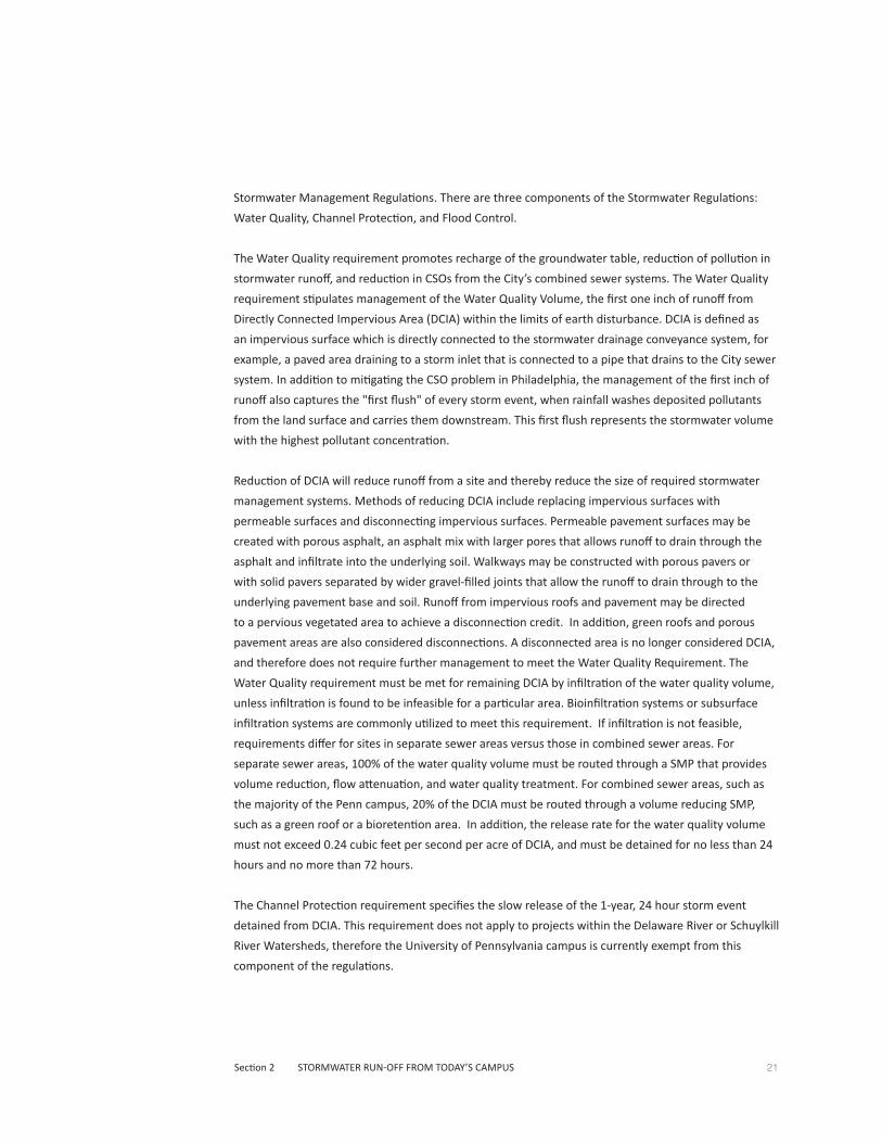
The Water Quality requirement promotes recharge of the groundwater table, reduction of pollution in
stormwater runoff, and reduction in CSOs from the City’s combined sewer systems. The Water Quality
requirement stipulates management of the Water Quality Volume, the first one inch of runoff from
Directly Connected Impervious Area (DCIA) within the limits of earth disturbance. DCIA is defined as
an impervious surface which is directly connected to the stormwater drainage conveyance system, for
example, a paved area draining to a storm inlet that is connected to a pipe that drains to the City sewer
system. In addition to mitigating the CSO problem in Philadelphia, the management of the first inch of
runoff also captures the "first flush" of every storm event, when rainfall washes deposited pollutants
from the land surface and carries them downstream. This first flush represents the stormwater volume
with the highest pollutant concentration.
Reduction of DCIA will reduce runoff from a site and thereby reduce the size of required stormwater
management systems. Methods of reducing DCIA include replacing impervious surfaces with
permeable surfaces and disconnecting impervious surfaces. Permeable pavement surfaces may be
created with porous asphalt, an asphalt mix with larger pores that allows runoff to drain through the
asphalt and infiltrate into the underlying soil. Walkways may be constructed with porous pavers or
with solid pavers separated by wider gravel-filled joints that allow the runoff to drain through to the
underlying pavement base and soil. Runoff from impervious roofs and pavement may be directed
to a pervious vegetated area to achieve a disconnection credit. In addition, green roofs and porous
pavement areas are also considered disconnections. A disconnected area is no longer considered DCIA,
and therefore does not require further management to meet the Water Quality Requirement. The
Water Quality requirement must be met for remaining DCIA by infiltration of the water quality volume,
unless infiltration is found to be infeasible for a particular area. Bioinfiltration systems or subsurface
infiltration systems are commonly utilized to meet this requirement. If infiltration is not feasible,
requirements differ for sites in separate sewer areas versus those in combined sewer areas. For
separate sewer areas, 100% of the water quality volume must be routed through a SMP that provides
volume reduction, flow attenuation, and water quality treatment. For combined sewer areas, such as
the majority of the Penn campus, 20% of the DCIA must be routed through a volume reducing SMP,
such as a green roof or a bioretention area. In addition, the release rate for the water quality volume
must not exceed 0.24 cubic feet per second per acre of DCIA, and must be detained for no less than 24
hours and no more than 72 hours.
The Channel Protection requirement specifies the slow release of the 1-year, 24 hour storm event
detained from DCIA. This requirement does not apply to projects within the Delaware River or Schuylkill
River Watersheds, therefore the University of Pennsylvania campus is currently exempt from this
component of the regulations.
22 A Stormwater Master Plan For the University of Pennsylvania
The Flood Control requirement reduces the severity of flooding in areas downstream of the
development site, and also reduces the frequency and duration of CSOs. Under this component,
development projects are required to meet peak runoff rates for post-development conditions that are
equal to or less than those from the pre-development conditions for up to the 100-year storm event
(8.4 inch rainfall event). Projects that can directly discharge to the Delaware or Schuylkill River main
channels without using City infrastructure are not subject to this requirement.
The most significant improvement that can be made to a land development project, in terms of
reducing stormwater management requirements, is the reduction of existing pre-development
impervious area by 20 percent. Projects that provide this 20% reduction in impervious area are exempt
from the Flood Control requirement, thereby eliminating the need for large detention systems and the
larger pipes needed to convey the 100-year storm to the systems.
Another incentive offered by PWD is the designation as a Green Project. For redevelopment projects
that disconnect 95% or more of the DCIA, PWD provides an expedited Green Project Review from
PWD, in which the department will provide a review letter within five business days of submission.
Subsequent revised submissions also receive a response within five days. Since 95% or more of the
proposed DCIA is disconnected, no further stormwater management is required. An example of a
Green Project would be a building with a green roof, whose paved surfaces are constructed of porous
pavement. In such a Green Project, a maximum of five percent of the site’s hard surfaces can be
impervious.
The Challenge of Compliance with the PWD RegulationsAn original goal for the Stormwater Master Plan was to assess the feasibility of managing one inch
of runoff from all campus impervious surfaces. Another goal of the plan was to seek "campus-wide"
solutions to stormwater management, rather than continue with the current "project-by-project"
approach.
Because the University is only responsible for stormwater runoff generated by its property not
including the City’s rights-of-way (and is charged stormwater fees by PWD only for that property), the
Stormwater Master Plan currently considers only that private property. The plan does not consider
runoff from the City’s streets and sidewalks, though could be revised in the future to do so. For
example, the University may choose to create "green streets" in conjunction with the City, where runoff
from private and public areas is combined and managed in shared stormwater management systems.
To get an overall understanding of the magnitude of the effort required to manage one inch of
runoff from all University impervious areas, all impervious surface areas within the plan’s study area
were inventoried and the volume of water generated by one inch of runoff from those surfaces was
calculated. Aerial mapping provided by the University, updated to reflect recent construction projects,
was used to determine the total building and ground-level impervious area within the study area.

23Section 2 STORMWATER RUN-OFF FROM TODAY’S CAMPUS
The inventory areas (rounded to the nearest 1000 square feet) are as follows:
• Total Campus Study Area
(not including City street rights-of-way): 10,958,000 sf (251.6 acres)
• Total Roof Area: 4,051,000 sf (93.0 acres)
• Total Ground-Level Impervious Area: 3,787,000 sf (86.9 acres)
• Total Impervious Area: 7,838,000 sf (179.9 acres)
The study area is approximately 72% impervious.
• One inch of runoff from all campus impervious surfaces generates a stormwater volume of:
653,200 cubic feet, or approximately 4,900,000 gallons of water
*Note: the areas above include existing green roofs, porous pavement areas, and other areas
managed by existing stormwater management facilities.
To illustrate the magnitude of this stormwater volume, the following graphics show a representation
of the runoff volume "stored" over the football field in Franklin Field stadium and provide simple
assessments of where the University’s management of one inch of runoff stands today. Additional
figures show how increases of different stormwater management practices across campus would
impact the University’s compliance with PWD’s goal of managing one inch of runoff from all
impervious surfaces.
• One inch of run-off from the study area's impervious area would flood the football field area within
Franklin Field to a depth of approximatley 14 feet.
14'
24 A Stormwater Master Plan For the University of Pennsylvania
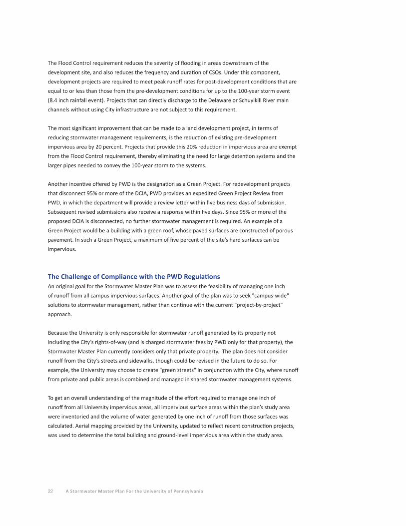
• If the City's street right-of ways within the study area are included (approximately 50 acres), one inch of run-off would fill an additional 3.7 feet, totalling a depth of 17.7 feet.
3.7'
17.7'
14'
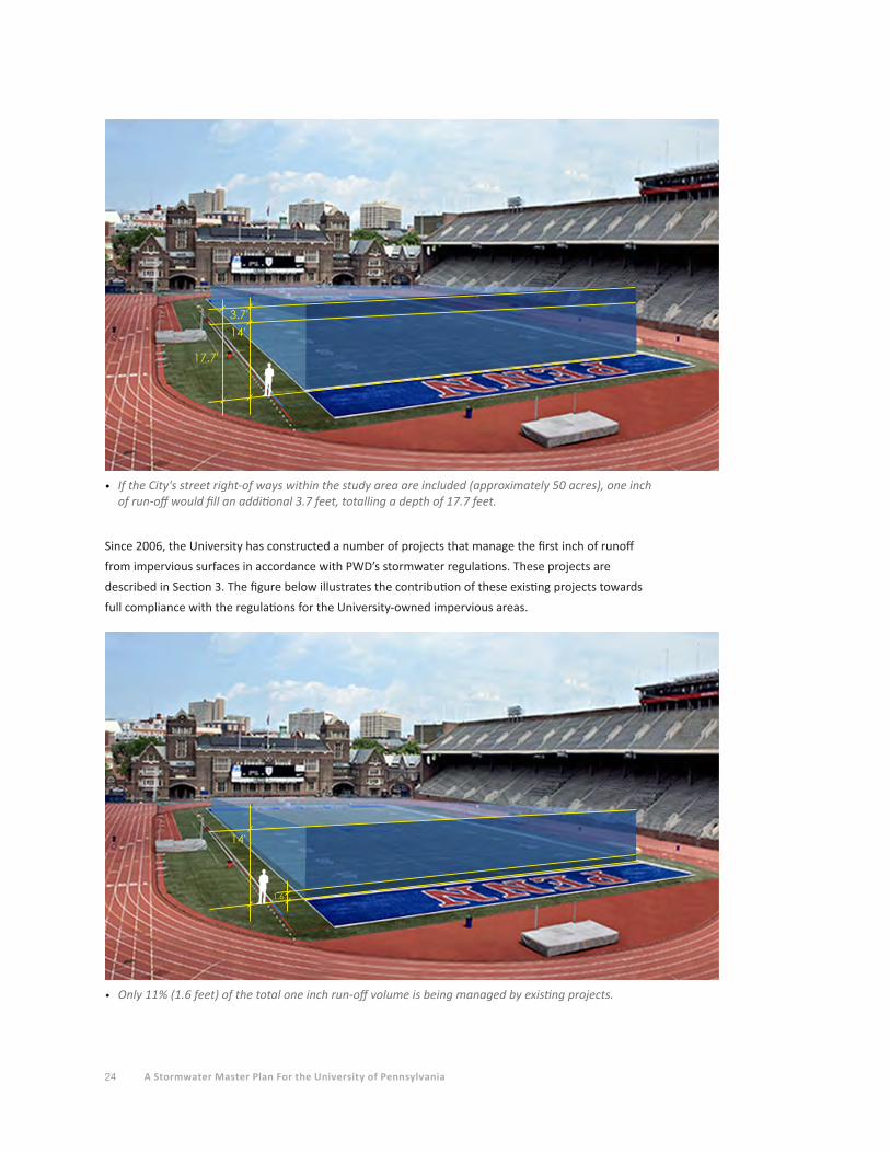
Since 2006, the University has constructed a number of projects that manage the first inch of runoff
from impervious surfaces in accordance with PWD’s stormwater regulations. These projects are
described in Section 3. The figure below illustrates the contribution of these existing projects towards
full compliance with the regulations for the University-owned impervious areas.
• Only 11% (1.6 feet) of the total one inch run-off volume is being managed by existing projects.
1.6
14'

25Section 2 STORMWATER RUN-OFF FROM TODAY’S CAMPUS
• Approximately 13% (1.8 feet) of the total one inch run-off volume would be managed if 25% of all building roofs were green roofs.
• Approximately 13% (1.8 feet) of the total one inch run-off volume would be managed if 25% of all building roofs were managed by ground-level SMPs.
• Approximately 12% (1.7 feet) of the total one inch run-off volume would be managed if 25% of all ground-level impervious areas was managed by SMPs.
• If all three of these practices were achieved, together only 38% of the University's one inch run-off volume would be managed.
To illustrate the challenge of managing one inch of runoff from all University impervious surfaces, the
figure below indicates the level of compliance that would be achieved if:
• 25 % of all campus building roofs were constructed or retrofitted with green roofs (24 acres
of green roofs out of 97 total roof acres),
• 25 % of all campus building roofs were managed by infiltration/detention systems at ground
level (an additional 24 acres of managed roofs out of 97 total roof acres),
&
• 25 % of all ground level impervious area was managed by infiltration/detention systems
(22 acres of managed ground-level impervious area out of 88 acres of total ground-level
impervious area).
1.81.8
1.7
14'
26 A Stormwater Master Plan For the University of Pennsylvania
There are two major challenges to managing one inch of runoff from all the University's impervious
surfaces with PWD’s regulations for the entire campus:
1. The construction of and the significant level of investment required to achieve the
improvements represented on the preceding page would result in less than 40% compliance
with the regulations.
2. A "campus-wide" approach to stormwater management, instead of a "project-by-project"
approach is improbable, as discussed below.
Additional challenges are described below.
A Sustainable Approach to Stormwater ManagementA campus-wide approach to stormwater management, instead of a project-by-project approach, would
entail the conveyance of runoff from large areas of the campus to several large "regional" facilities.
Stormwater runoff from a project would not necessarily be detained and/or infiltrated on the project’s
site, but instead would be drained via pipes to a facility located some distance from the project site.
There are several obstacles that make a campus-wide approach to stormwater management physically
impractical and cost-prohibitive.
The efficient storage of large volumes of stormwater runoff requires large areas of land with no
buildings. Such large open areas are scarce on the campus, and the few parcels that hold potential for a
large regional facility are in consideration for future development.
Even if large areas of open ground were available, the existing City infrastructure creates obstacles
to convey stormwater across the City streets that run through the campus. Numerous public utilities
(water, sewer, gas, electric, telephone) of varied sizes and at varied depths are located within the City
street rights-of-way. These present significant obstacles to transporting stormwater from one side of a
street to a regional stormwater management facility on the opposite side of the street. A storm sewer,
flowing by gravity, would be required to convey the runoff across the street, and existing utilities may
need to be relocated to eliminate interference with the proposed cross-street sewer. Such construction
would also require traffic interruptions and costly pavement restoration.
There may be locations on campus where such "cross-block" transfer of stormwater is feasible, but
the scope of this plan does not include analysis of all of the existing City infrastructure within the
streets on campus.
Instead, in addition to identifying potential SMPs for individual buildings and paved areas, this plan
assesses the feasibility of shared stormwater management facilities on a block-by-block basis. The
City streets act as the boundaries of drainage areas for each block, and the plan identifies potential
opportunities to manage stormwater within each block.
This methodology is in keeping with a basic principle of sustainable stormwater management: rainfall is
best managed where it falls, so as to most closely mimic the natural processes that are being disrupted
by the built environment. Ideally, a portion of the rainfall will be infiltrated. Another portion will be

27Section 2 STORMWATER RUN-OFF FROM TODAY’S CAMPUS
taken up by planting and evapotranspiration. The remaining rainfall should be captured and slowly
released from the site so as to minimize downstream impacts and, in the case of Philadelphia, reduce
the frequency and magnitude of Combined Sewer Overflows (CSO).
Future iterations of this plan may explore cross-block stormwater transfers, including linkages
of stormwater management practices such as cisterns capturing roof runoff from multiple buildings or
underground infiltration/detention systems managing runoff from multiple parking areas and buildings.
While managing one inch of runoff for the entire campus appears infeasible, it is a relevant metric
against which to measure the University’s progress toward reducing its contribution to the Combined
Sewer Overflow problem.
The following sections of the master plan review the recently-constructed projects that include
stormwater management practices and that have set the University on the path toward managing one
inch of runoff from all impervious surfaces. After that review, potential new stormwater management
technologies and techniques are discussed. Then, a block-by-block analysis of the campus is provided
to aid in identifying potential stormwater retrofit projects as well as localized shared stormwater
facilities that could be constructed when new construction takes place. That information can be used
in conjunction with the Penn Connects 2.0 plan to lead the University toward increased stormwater
management sustainability.

28 A Stormwater Master Plan For the University of Pennsylvania

Section 1 EXECUTIVE SUMMARY 29
Section 1 EXECUTIVE SUMMARY
Section 2 STORMWATER RUN-OFF FROM TODAY’S CAMPUS
Section 3 STORMWATER MANAGEMENT ON TODAY’S CAMPUS
Section 4 POTENTIAL STORMWATER MANAGEMENT PRACTICES FOR FUTURE PROJECTS
Section 5 FINDING SUSTAINABLE STORMWATER MANAGEMENT OPPORTUNITIES
Section 6 STORMWATER MANAGEMENT COSTS AND PWD FEES
Section 7 OPERATIONS AND MAINTENANCE CONSIDERATIONS
Section 8 LEGISLATION ISSUES AND FUNDING OPPORTUNITIES
Section 9 RECOMMENDATIONS
Section 10 APPENDICES
A. Representative Stormwater Management Details
B. Stormwater Management Model
C. References
D. Acknowledgements
30 A Stormwater Master Plan For the University of Pennsylvania
STORMWATER MANAGEMENT ON TODAY’S CAMPUS
Since the adoption of the PWD stormwater regulations in 2006, Penn has completed (or has
under construction) more than a dozen projects that incorporate stormwater management
facilities. These projects include green roofs, porous pavement, and bioretention areas, as well
as subsurface infiltration/detention systems and water quality management devices. Some of the
projects also received credit from PWD for pavement disconnections and tree credits.
Since 2006, Penn has been subject to compliance review and approval from PWD’s Stormwater
Plan Review Group. The following projects have gone through this review and approval process:
PROJECT APPROVAL DATE
• George Weiss Pavilion February 4, 2009
• Music Building February 28, 2009
• Cira South Garage March 29, 2009
• Class of '62 Walkway May 14, 2009
• Woodland Walk July 14, 2009
• Penn Park April 29, 2010
• Golkin Law School May 7, 2010
• Singh Nanotechnology Center February 23, 2011
• Locust Walk Reconstruction May 2, 2011
• Shoemaker Green July 27, 2011
(Note: A number of additional projects were initiated during the preparation of this plan.)
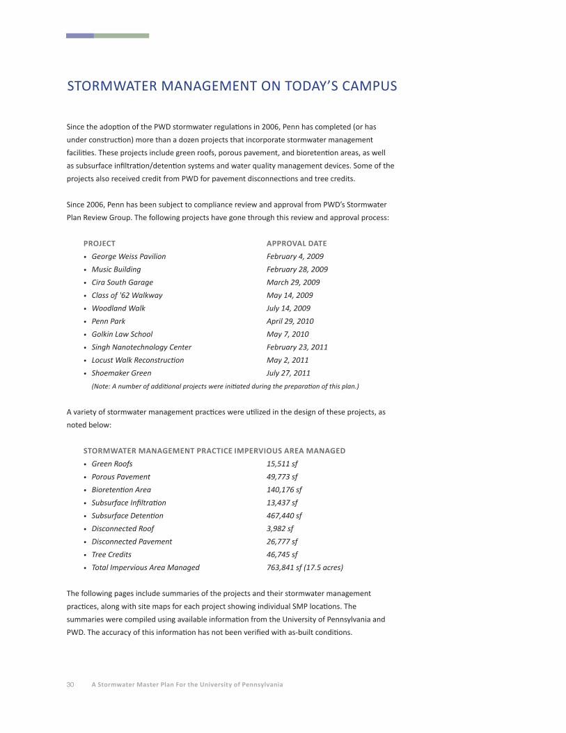
A variety of stormwater management practices were utilized in the design of these projects, as
noted below:
STORMWATER MANAGEMENT PRACTICE IMPERVIOUS AREA MANAGED
• Green Roofs 15,511 sf
• Porous Pavement 49,773 sf
• Bioretention Area 140,176 sf
• Subsurface Infiltration 13,437 sf
• Subsurface Detention 467,440 sf
• Disconnected Roof 3,982 sf
• Disconnected Pavement 26,777 sf
• Tree Credits 46,745 sf
• Total Impervious Area Managed 763,841 sf (17.5 acres)
The following pages include summaries of the projects and their stormwater management
practices, along with site maps for each project showing individual SMP locations. The
summaries were compiled using available information from the University of Pennsylvania and
PWD. The accuracy of this information has not been verified with as-built conditions.

31Section 3 STORMWATER MANAGEMENT ON TODAY'S CAMPUS
Existing Stormwater Projects 1. George Weiss Pavilion
2. Music Building
3. Cira South Garage
4. Class of ‘62 Walk
5. Woodland Walk
6. Penn Park
7. Golkin Law School
8. Singh Nanotechnology Center
9. Locust Walk
10. Shoemaker Green
WALL
78
3
6
10
1
24
5
9 9

32 A Stormwater Master Plan For the University of Pennsylvania
George Weiss Pavilion200 South 32nd Street
Approved - February 4, 2009
Project DescriptionThe George Weiss Pavilion project is located east of 33rd Street, within the northern arcade of Franklin
Field and involved 0.78 acres of earth disturbance. The project included the construction of an addition
within the existing Franklin Field footprint and the removal of the impervious driveway, parking area,
and sidewalk. The removed areas were replaced with porous pavement, consisting of concrete pavers
and porous asphalt. Inlets were added for drainage improvement, which tie into the combined sewer
within the driveway. This section of driveway is included within the City’s Utility Right-of-Way; however
the University owns this section of the driveway and is responsible for operation and maintenance of
the surface improvements.
Stormwater Management DescriptionThe project decreased impervious coverage by more than 20% from pre-development conditions;
therefore it was only subject to PWD’s Water Quality component of the Philadelphia Stormwater
Regulations and was exempt from Channel Protection and Flood Control requirements. This decrease
in impervious coverage was accomplished by the construction of areas of porous pavement. Since
approximately 95% of the proposed surface is considered disconnected, stormwater management
practices were not required.
Porous pavements at Weiss Pavilion

33Section 3 STORMWATER MANAGEMENT ON TODAY'S CAMPUS
Location map - Weiss Pavilion
Inlets have 15-inch sumps and cast iron traps. The porous asphalt is approximately 11,650 square
feet in area and consists of a 4-inch surface course over stone, underlain by geotextile fabric. In order
to maintain a level bottom, the stone depth varies from 8-18 inches depending on the slope of the
surface. Permeable pavers are utilized in approximately 15,320 square feet in area. The pavers are
Pine Hall concrete pavers with ¼ inch joint openings filled with aggregate. There is 9-12 inches of stone
below the pavers, underlain by geotextile fabric.
• Porous Pavement: 27,000 sf
• Total Impervious area (managed or disconnected): 27,000 sf
• Volume of runoff managed: 2247 cubic feet
Porous pavements at Weiss Pavilion and Shoemaker Green
PROJECT BOUNDARY
EXISTING POROUS PAVEMENT
EXISTING GREEN SPACE
EXISTING TREE CREDITS
Palestra
Hutchinson Gym
Ringe Squash Courts
Shoemaker Green
Franklin Field
Weightman Hall
Dunning
Hayden Hall
Towne Building
Levy Tennis
Pavilion
33rd
Stre
et
34 A Stormwater Master Plan For the University of Pennsylvania
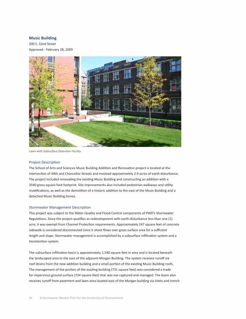
Music Building200 S. 32nd Street
Approved - February 28, 2009
Lawn with Subsurface Detention Facility
Project DescriptionThe School of Arts and Sciences Music Building Addition and Renovation project is located at the
intersection of 34th and Chancellor Streets and involved approximately 2.9 acres of earth disturbance.
The project included renovating the existing Music Building and constructing an addition with a
3540 gross square foot footprint. Site improvements also included pedestrian walkways and utility
modifications, as well as the demolition of a historic addition to the east of the Music Building and a
detached Music Building Annex.
Stormwater Management DescriptionThis project was subject to the Water Quality and Flood Control components of PWD's Stormwater
Regulations. Since the project qualifies as redevelopment with earth disturbance less than one (1)
acre, it was exempt from Channel Protection requirements. Approximately 247 square feet of concrete
sidewalk is considered disconnected since it sheet flows over grass surface area for a sufficient
length and slope. Stormwater management is accomplished by a subsurface infiltration system and a
bioretention system.
The subsurface infiltration basin is approximately 1,540 square feet in area and is located beneath
the landscaped area to the east of the adjacent Morgan Building. The system receives runoff via
roof drains from the new addition building and a small portion of the existing Music Building roofs.
The management of the portion of the existing building (731 square feet) was considered a trade
for impervious ground surface (724 square feet) that was not captured and managed. The basin also
receives runoff from pavement and lawn area located east of the Morgan building via inlets and trench
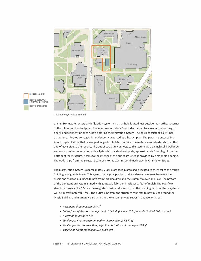
35Section 3 STORMWATER MANAGEMENT ON TODAY'S CAMPUS
Location map - Music Building
PROJECT BOUNDARY
EXISTING SUBSURFACE INFILTRATION/DETENTION
EXISTING GREEN SPACE
Chemistry Complex
drains. Stormwater enters the infiltration system via a manhole located just outside the northeast corner
of the infiltration bed footprint. The manhole includes a 3-foot deep sump to allow for the settling of
debris and sediment prior to runoff entering the infiltration system. The basin consists of six 24-inch
diameter perforated corrugated metal pipes, connected by a header pipe. The pipes are encased in a
4-foot depth of stone that is wrapped in geotextile fabric. A 6-inch diameter cleanout extends from the
end of each pipe to the surface. The outlet structure connects to the system via a 15-inch solid wall pipe
and consists of a concrete box with a 1/4-inch thick steel weir plate, approximately 5 feet high from the
bottom of the structure. Access to the interior of the outlet structure is provided by a manhole opening.
The outlet pipe from the structure connects to the existing combined sewer in Chancellor Street.
The bioretention system is approximately 200 square feet in area and is located to the west of the Music
Building, along 34th Street. This system manages a portion of the walkway pavement between the
Music and Morgan buildings. Runoff from this area drains to the system via overland flow. The bottom
of the bioretention system is lined with geotextile fabric and includes 2-feet of mulch. The overflow
structure consists of a 12-inch square grated drain and is set so that the ponding depth of these systems
will be approximately 0.8 feet. The outlet pipe from the structure connects to new piping around the
Music Building and ultimately discharges to the existing private sewer in Chancellor Street.
• Pavement disconnection: 247 sf
• Subsurface infiltration management: 6,343 sf (include 731 sf outside Limit of Disturbance)
• Bioretention Area: 757 sf
• Total Impervious area (managed or disconnected): 7,347 sf
• Total Impervious area within project limits that is not managed: 724 sf
• Volume of runoff managed: 612 cubic feet
Moore School
GRW
Levine
Skirkanich
Towne Building
Bennett Hall
Music Building
Morgan
Hayden HallVagelos IAST Labs
1958 Wing
Irvine Auditorium
During Wing
Fischer Fine Arts Library
Meyerson Hall
Jaffe
Weightman Hall
33rd
Stre
et
34th
Str
eet

36 A Stormwater Master Plan For the University of Pennsylvania
Cira South Garage120 S. 30th Street
Approved - March 29, 2009
Top of garage
Project DescriptionThe Cira Centre South project is located at 2930 Chestnut Street, running the length of the block on
30th Street between Chestnut and Walnut Streets. Amtrak rail lines run along the east side of the site.
The University is currently leasing this property to Brandywine Cira South LP. Formerly, this property
housed the United States Post Office Truck Terminal Annex, which was demolished as part of this
project to make way for the construction of a 11-story parking garage and two proposed flanking
mixed-use towers. The project involved 1.9 acres of earth disturbance. The footprint of the garage is
approximately 40,000 square feet at the lowest three tiers and approximately 53,850 square feet for
the upper floors, which overhang an Amtrak rail spur on the east.
Stormwater Management DescriptionThe project in its current state, decreased impervious coverage by more than 20% from pre-
development conditions; therefore it was subject to the Water Quality component of PWD's
Stormwater Regulations and was exempt from Channel Protection and Flood Control requirements.
This was accomplished by removal of impervious surfaces and replacement with pervious areas.
Management of DCIA is accomplished by a subsurface detention system.
The subsurface detention system is approximately 1,254 square feet in area and is installed below the
concrete floor of the garage. The detention system receives garage roof runoff from the roof drainage
system. The basins consists of a concrete box that connects to an outlet structure to detain and slowly
release stored water. The outlet structure is a concrete box that contains a steel weir plate with one
3-inch diameter orifice and two 8-inch diameter orifices. The opposite side of the weir plate contains
an outlet pipe that connects to an inlet containing a backflow preventer device prior to connecting to
37Section 3 STORMWATER MANAGEMENT ON TODAY'S CAMPUS
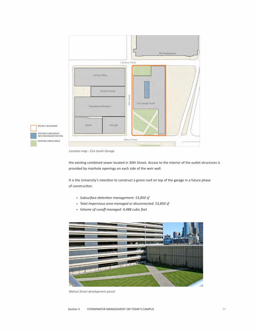
Location map - Cira South Garage
Walnut Street development parcel
the existing combined sewer located in 30th Street. Access to the interior of the outlet structures is
provided by manhole openings on each side of the weir wall.
It is the University's intention to construct a green roof on top of the garage in a future phase
of construction.
• Subsurface detention management: 53,850 sf
• Total Impervious area managed or disconnected: 53,850 sf
• Volume of runoff managed: 4,488 cubic feet
IRS Headquarters
US Post Office
Horizon House
Translational Research
WXPN AFSCME
Cira Garage South
30th
Str
eet
Walnut Street
Chestnut Street
PROJECT BOUNDARY
EXISTING SUBSURFACE INFILTRATION/DETENTION
EXISTING GREEN SPACE

38 A Stormwater Master Plan For the University of Pennsylvania
Class of ‘62 Walk37th Street
Approved - May 14, 2009
Looking South
Project DescriptionThe Class of 62’ Walkway project involved the reconstruction of the 37th Street walkway between
Walnut Street and Locust Walk. Impervious driveway and sidewalk areas wereremoved and replaced
with porous pavement and landscaping. Inlets were added for drainage improvement, which tie into
the combined sewer within the walkway. This section of 37th Street is included within the City’s Utility
Right-of-Way; however the University owns this section of the walk and is responsible for operation and
maintenance of the surface improvements.
Stormwater Management DescriptionThe project decreased impervious coverage by more than 20% from pre-development conditions;
therefore it was subject to the Water Quality component of PWD's Stormwater Regulations and was
exempt from Channel Protection and Flood Control requirements. Areas of new impervious pavement
were managed by one of two subsurface infiltration basins.
The permeable pavement is located within the walkway. It is approximately 4,200 square feet in area
and consists of permeable brick paver units separated by ¼-inch wide joints filled with aggregate. The
pavers are underlain by three layers of stone varying in size, for a total thickness of 12-24 inches and
lined with a non-woven geotextile fabric.
There are two (2) subsurface infiltration systems, Basins A and B, that are utilized for stormwater
management at the site. Runoff from impervious walkway areas is collected by inlets and separately
conveyed to one of the two basins. Basin A is located at the driveway entrance to the south of the

39Section 3 STORMWATER MANAGEMENT ON TODAY'S CAMPUS
Location map - Class of '62 Walk
PROJECT BOUNDARY
EXISTING GREEN ROOF
EXISTING POROUS PAVEMENT
EXISTING SUBSURFACE INFILTRATION/DETENTION
EXISTING GREEN SPACE
Annenberg Center and consists of two separate bed areas connected by an 18-inch pipe. The southern
bed is approximately 102 square feet in area and the northern bed is approximately 180 square feet.
Basin B is approximately 141 square feet in area and is situated further north of Basin A, approximately
100 feet south of Walnut Street, adjacent to the Annenberg Center. The basins consist of two rows
of 18-inch diameter perforated plastic pipe connected with manifold pipes and an outlet structure
at one end. The pipes are surrounded by a 3-foot depth of stone, encased within a geotextile fabric.
The outlet structure for each basin consists of a concrete box with a 6-inch thick concrete weir wall
in the center. The intent of the weir wall is to ensure infiltration of the stored water within the basin
while allowing larger storm events to overflow the weir to the outlet pipe on the opposite side of
the structure. The outlet pipes are protected by trap devices and connect to the private sewer in the
walkway. Access to the interior of the outlet structures for maintenance is provided by a manhole.
• Permeable Pavement: 4,200 sf
• Subsurface Infiltration Basin A Management: 4355 sf
• Subsurface Infiltration Basin B Management: 2739 sf
• Total Impervious area managed or disconnected: 11,294 sf
• Volume of runoff managed: 941 cubic feet
Phi G
amm
a D
elta
Phi S
igm
a Ka
ppa
Lauder Fischer
Inn at Penn
Pottruck Fitness Center
Module 6 Retail/Garage
Huntsman Hall
Psych Labs
Graduate School of Education
Caster
Stiteler Hall
Annenberg CenterAnnenberg
Steinberg/Deitrich HallSteinberg
Conference Center
McNeil BuildingKappa Sigma
Phi Delta Theta
Locu
st
Hou
se
Colo
nial
Pe
nn
Del
ta P
si
Delta Phi
Lauder Fischer
Penn Bookstore
Phi G
amm
a D
elta
Phi S
igm
a Ka
ppa
Addams Hall
APPC
The Arch
The Castle
Walnut Street
37th
Str
eet
Locust WalkLocust Walk
40 A Stormwater Master Plan For the University of Pennsylvania
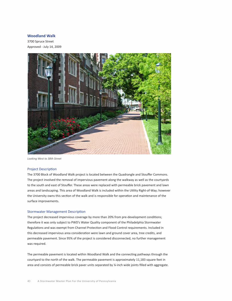
Woodland Walk3700 Spruce Street
Approved - July 14, 2009
Looking West to 38th Street
Project DescriptionThe 3700 Block of Woodland Walk project is located between the Quadrangle and Stouffer Commons.
The project involved the removal of impervious pavement along the walkway as well as the courtyards
to the south and east of Stouffer. These areas were replaced with permeable brick pavement and lawn
areas and landscaping. This area of Woodland Walk is included within the Utility Right-of-Way; however
the University owns this section of the walk and is responsible for operation and maintenance of the
surface improvements.
Stormwater Management DescriptionThe project decreased impervious coverage by more than 20% from pre-development conditions;
therefore it was only subject to PWD’s Water Quality component of the Philadelphia Stormwater
Regulations and was exempt from Channel Protection and Flood Control requirements. Included in
this decreased impervious area consideration were lawn and ground cover area, tree credits, and
permeable pavement. Since 95% of the project is considered disconnected, no further management
was required.
The permeable pavement is located within Woodland Walk and the connecting pathways through the
courtyard to the north of the walk. The permeable pavement is approximately 11,183 square feet in
area and consists of permeable brick paver units separated by ¼-inch wide joints filled with aggregate.
41Section 3 STORMWATER MANAGEMENT ON TODAY'S CAMPUS
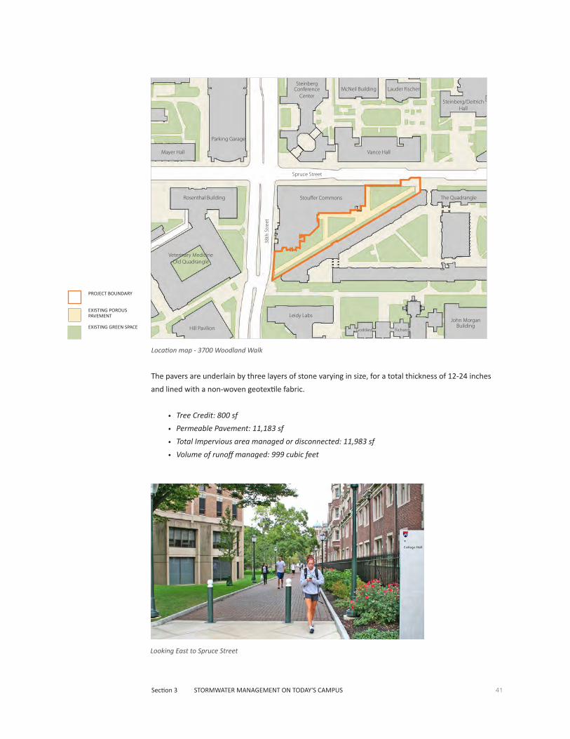
Location map - 3700 Woodland Walk
PROJECT BOUNDARY
EXISTING POROUS PAVEMENT
EXISTING GREEN SPACE
The pavers are underlain by three layers of stone varying in size, for a total thickness of 12-24 inches
and lined with a non-woven geotextile fabric.
• Tree Credit: 800 sf
• Permeable Pavement: 11,183 sf
• Total Impervious area managed or disconnected: 11,983 sf
• Volume of runoff managed: 999 cubic feet
Looking East to Spruce Street
Lauder Fischer
The Quadrangle
Vance Hall
Steinberg Conference
Center
Stouffer CommonsRosenthal Building
Hill Pavilion
Veterinary Medicine Old Quadrangle
Leidy Labs
Goddard Richards
John Morgan Building
Parking Garage
McNeil Building
Steinberg/Deitrich Hall
Mayer Hall
Spruce Street
38th
Str
eet
42 A Stormwater Master Plan For the University of Pennsylvania
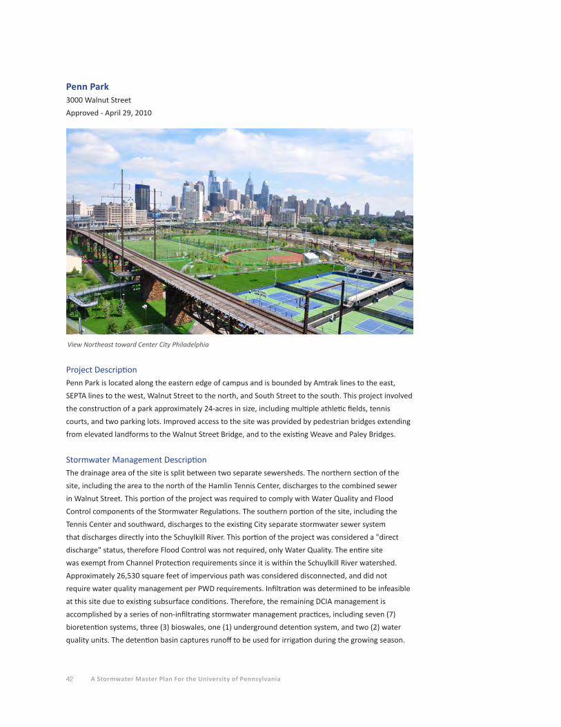
Project DescriptionPenn Park is located along the eastern edge of campus and is bounded by Amtrak lines to the east,
SEPTA lines to the west, Walnut Street to the north, and South Street to the south. This project involved
the construction of a park approximately 24-acres in size, including multiple athletic fields, tennis
courts, and two parking lots. Improved access to the site was provided by pedestrian bridges extending
from elevated landforms to the Walnut Street Bridge, and to the existing Weave and Paley Bridges.
Stormwater Management DescriptionThe drainage area of the site is split between two separate sewersheds. The northern section of the
site, including the area to the north of the Hamlin Tennis Center, discharges to the combined sewer
in Walnut Street. This portion of the project was required to comply with Water Quality and Flood
Control components of the Stormwater Regulations. The southern portion of the site, including the
Tennis Center and southward, discharges to the existing City separate stormwater sewer system
that discharges directly into the Schuylkill River. This portion of the project was considered a "direct
discharge" status, therefore Flood Control was not required, only Water Quality. The entire site
was exempt from Channel Protection requirements since it is within the Schuylkill River watershed.
Approximately 26,530 square feet of impervious path was considered disconnected, and did not
require water quality management per PWD requirements. Infiltration was determined to be infeasible
at this site due to existing subsurface conditions. Therefore, the remaining DCIA management is
accomplished by a series of non-infiltrating stormwater management practices, including seven (7)
bioretention systems, three (3) bioswales, one (1) underground detention system, and two (2) water
quality units. The detention basin captures runoff to be used for irrigation during the growing season.
Penn Park3000 Walnut Street
Approved - April 29, 2010
View Northeast toward Center City Philadelphia
43Section 3 STORMWATER MANAGEMENT ON TODAY'S CAMPUS
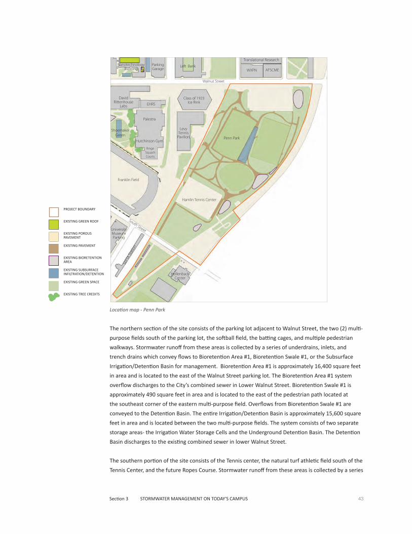
The northern section of the site consists of the parking lot adjacent to Walnut Street, the two (2) multi-
purpose fields south of the parking lot, the softball field, the batting cages, and multiple pedestrian
walkways. Stormwater runoff from these areas is collected by a series of underdrains, inlets, and
trench drains which convey flows to Bioretention Area #1, Bioretention Swale #1, or the Subsurface
Irrigation/Detention Basin for management. Bioretention Area #1 is approximately 16,400 square feet
in area and is located to the east of the Walnut Street parking lot. The Bioretention Area #1 system
overflow discharges to the City’s combined sewer in Lower Walnut Street. Bioretention Swale #1 is
approximately 490 square feet in area and is located to the east of the pedestrian path located at
the southeast corner of the eastern multi-purpose field. Overflows from Bioretention Swale #1 are
conveyed to the Detention Basin. The entire Irrigation/Detention Basin is approximately 15,600 square
feet in area and is located between the two multi-purpose fields. The system consists of two separate
storage areas- the Irrigation Water Storage Cells and the Underground Detention Basin. The Detention
Basin discharges to the existing combined sewer in lower Walnut Street.
The southern portion of the site consists of the Tennis center, the natural turf athletic field south of the
Tennis Center, and the future Ropes Course. Stormwater runoff from these areas is collected by a series
Location map - Penn Park
Hollenback Annex
SEPT
A St
atio
n
Translational Research
WXPN AFSCME
David Rittenhouse
Labs
Palestra
Hutchinson Gym
Ringe Squash Courts
Shoemaker Green
Franklin Field
Left Bank
University Museum Parking
Levy Tennis
Pavilion
Hamlin Tennis Center
Hollenback Center
Penn Park
Class of 1923 Ice RinkEHRS
Nanotechnology Building
Parking Garage
Walnut Street
South Street
PROJECT BOUNDARY
EXISTING GREEN ROOF
EXISTING POROUS PAVEMENT
EXISTING PAVEMENT
EXISTING BIORETENTION AREA
EXISTING SUBSURFACE INFILTRATION/DETENTION
EXISTING GREEN SPACE
EXISTING TREE CREDITS
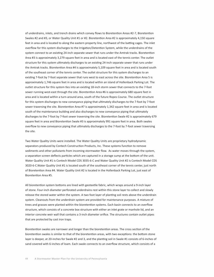
44 A Stormwater Master Plan For the University of Pennsylvania
of underdrains, inlets, and trench drains which convey flows to Bioretention Areas #2-7, Bioretention
Swales #2 and #3, or Water Quality Unit #1 or #2. Bioretention Area #2 is approximately 4,150 square
feet in area and is located to along the eastern property line, northwest of the batting cages. The inlet
overflow for this system discharges to the Irrigation/Detention System, while the underdrains of the
system connect to an existing 24-inch separate sewer that runs under the Amtrak tracks. Bioretention
Area #3 is approximately 3,279 square feet in area and is located east of the tennis center. The outlet
structure for this system ultimately discharges to an existing 24-inch separate sewer that runs under
the Amtrak tracks. Bioretention Area #4 is approximately 5,109 square feet in area and is located south
of the southeast corner of the tennis center. The outlet structure for this system discharges to an
existing 7-foot by 7-foot separate sewer that runs west to east across the site. Bioretention Area 5 is
approximately 1,746 square feet in area and is located within an island of Hollenback Parking Lot. The
outlet structure for this system ties into an existing 18-inch storm sewer that connects to the 7-foot
sewer running west-east through the site. Bioretention Area #6 is approximately 680 square feet in
area and is located within a turn-around area, south of the future Ropes Course. The outlet structure
for this system discharges to new conveyance piping that ultimately discharges to the 7-foot by 7-foot
sewer traversing the site. Bioretention Area #7 is approximately 1,342 square feet in area and is located
south of the maintenance building and also discharges to new conveyance piping that ultimately
discharges to the 7-foot by 7-foot sewer traversing the site. Bioretention Swale #2 is approximately 679
square feet in area and Bioretention Swale #3 is approximately 991 square feet in area. Both swales
overflow to new conveyance piping that ultimately discharges to the 7-foot by 7-foot sewer traversing
the site.
Two Water Quality Units were installed. The Water Quality Units are proprietary hydrodynamic
separators produced by Contech Construction Products, Inc. These systems function to remove
sediments and other pollutants from incoming stormwater flow. As water moves through the system,
a separation screen deflects particles which are captured in a storage sump at the bottom of the unit.
Water Quality Unit #1 is Contech Model CDS 3035-6-C and Water Quality Unit #2 is Contech Model CDS
3020-6-C.Water Quality Unit #1 is located south of the southeast corner of the tennis center, just north
of Bioretention Area #4. Water Quality Unit #2 is located in the Hollenback Parking Lot, just east of
Bioretention Area #5.
All bioretention system bottoms are lined with geotextile fabric, which wraps around a 9-inch layer
of stone. Four-inch diameter perforated underdrains rest within this stone layer to collect and slowly
release the stored water within the system. A two foot layer of planting soil rests above the underdrain
system. Cleanouts from the underdrain system are provided for maintenance purposes. A mixture of
trees and grasses were planted within the bioretention systems. Each basin connects to an overflow
structure, which consists of a concrete box structure with either an inlet grate or manhole lid, and an
interior concrete weir wall that contains a 3-inch diameter orifice. The structures contain outlet pipes
that are protected by cast iron traps.
Bioretention swales are narrower and longer than the bioretention areas. The cross section of the
bioretention swales is similar to that of the bioretention areas, with two exceptions: the bottom stone
layer is deeper, at 20-inches for Swale #2 and 3, and the planting soil in Swale #1 consists of 6-inches of
sand covered with 6-inches of loam. Each swale connects to an overflow structure, which consists of a
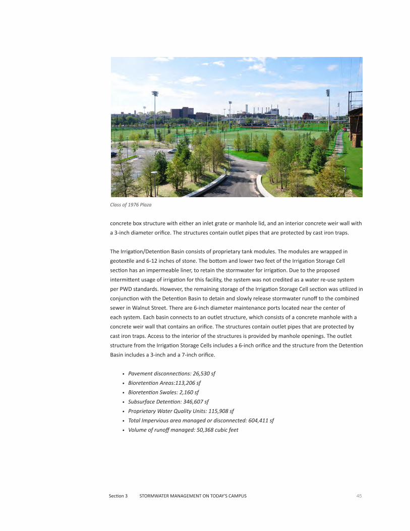
45Section 3 STORMWATER MANAGEMENT ON TODAY'S CAMPUS
concrete box structure with either an inlet grate or manhole lid, and an interior concrete weir wall with
a 3-inch diameter orifice. The structures contain outlet pipes that are protected by cast iron traps.
The Irrigation/Detention Basin consists of proprietary tank modules. The modules are wrapped in
geotextile and 6-12 inches of stone. The bottom and lower two feet of the Irrigation Storage Cell
section has an impermeable liner, to retain the stormwater for irrigation. Due to the proposed
intermittent usage of irrigation for this facility, the system was not credited as a water re-use system
per PWD standards. However, the remaining storage of the Irrigation Storage Cell section was utilized in
conjunction with the Detention Basin to detain and slowly release stormwater runoff to the combined
sewer in Walnut Street. There are 6-inch diameter maintenance ports located near the center of
each system. Each basin connects to an outlet structure, which consists of a concrete manhole with a
concrete weir wall that contains an orifice. The structures contain outlet pipes that are protected by
cast iron traps. Access to the interior of the structures is provided by manhole openings. The outlet
structure from the Irrigation Storage Cells includes a 6-inch orifice and the structure from the Detention
Basin includes a 3-inch and a 7-inch orifice.
• Pavement disconnections: 26,530 sf
• Bioretention Areas:113,206 sf
• Bioretention Swales: 2,160 sf
• Subsurface Detention: 346,607 sf
• Proprietary Water Quality Units: 115,908 sf
• Total Impervious area managed or disconnected: 604,411 sf
• Volume of runoff managed: 50,368 cubic feet
Class of 1976 Plaza

46 A Stormwater Master Plan For the University of Pennsylvania
Sansom Street view
Golkin Hall3501 Sansom Street
Approved - May 7, 200
Project DescriptionThe Golkin Hall project is located at 3501 Sansom Street and involved 0.7 acres of earth disturbance.
The project included the demolition of Pepper Hall and construction of the 3-story, Golkin Hall
building of 11,630 gross square foot footprint and adjacent driveways, pedestrian walkways, and other
associated improvements.
Stormwater Management DescriptionThis project was subject to the Water Quality and Flood Control components of PWD's Stormwater
Regulations. Since the project qualifies as redevelopment with earth disturbance less than one (1)
acre, it was exempt from Channel Protection requirements. A total of seven (7) new trees were planted
along Sansom Street for credit towards a reduction in DCIA. Porous asphalt was utilized in the driveway
resurfacing and porous pavers were utilized for the interior pathways within the rear courtyard area.
Portions of the new building include green roof areas, totaling approximately 5,403 square feet of the
roof. Portions of the existing "Goat" building, adjacent to the project, were retrofitted with a green roof
with an area of approximately 1,808 square feet. The green roofs consist of 3-4 inches of soil media
planted with a variety of grasses and sedges. The "Goat" building green roof was considered a trade
for new impervious ground cover along the front of the building that was not managed. Areas that are
considered disconnected, such as the green roof, porous asphalt, and permeable pavers, do not require
water quality management per PWD requirements. Management of DCIA is accomplished by two (2)
subsurface detention systems.
The porous asphalt is located within the drive aisle between the Golkin Hall and Silverman Hall. The
porous asphalt is approximately 2,755 square feet in area and consists of a 5-inch porous asphalt
layer on top of an 8-inch layer of stone and geotextile fabric. There is a 4-inch diameter perforated
underdrain within the stone layer of the porous asphalt section to assist with drainage. There is
also a surface inlet to collect and convey overflows from the pavement. The porous paver area is
approximately 4,669 square feet, is located within the interior courtyard behind the buildings, and is
used for the walkway surface. The brick pavers were installed with ¼-inch joints between them that are
filled with aggregate. There is an 18-inch layer of stone beneath the pavers. There is a 4-inch diameter
perforated underdrain at the east end of the courtyard, resting within a 6-inch sand course at the
bottom of the stone layer of the paver section to assist with drainage. There are also a series of trench
drains to collect and convey overflows from the pavement.
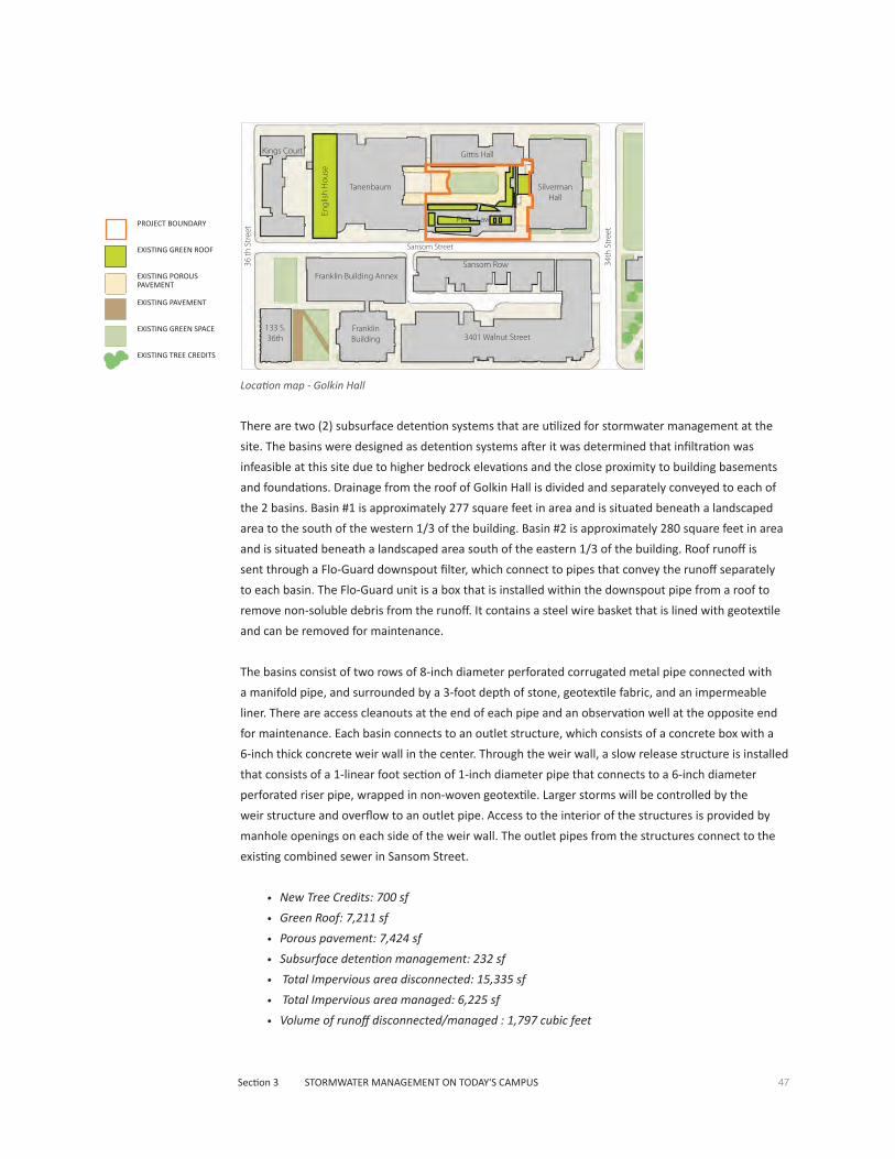
47Section 3 STORMWATER MANAGEMENT ON TODAY'S CAMPUS
Location map - Golkin Hall
There are two (2) subsurface detention systems that are utilized for stormwater management at the
site. The basins were designed as detention systems after it was determined that infiltration was
infeasible at this site due to higher bedrock elevations and the close proximity to building basements
and foundations. Drainage from the roof of Golkin Hall is divided and separately conveyed to each of
the 2 basins. Basin #1 is approximately 277 square feet in area and is situated beneath a landscaped
area to the south of the western 1/3 of the building. Basin #2 is approximately 280 square feet in area
and is situated beneath a landscaped area south of the eastern 1/3 of the building. Roof runoff is
sent through a Flo-Guard downspout filter, which connect to pipes that convey the runoff separately
to each basin. The Flo-Guard unit is a box that is installed within the downspout pipe from a roof to
remove non-soluble debris from the runoff. It contains a steel wire basket that is lined with geotextile
and can be removed for maintenance.
The basins consist of two rows of 8-inch diameter perforated corrugated metal pipe connected with
a manifold pipe, and surrounded by a 3-foot depth of stone, geotextile fabric, and an impermeable
liner. There are access cleanouts at the end of each pipe and an observation well at the opposite end
for maintenance. Each basin connects to an outlet structure, which consists of a concrete box with a
6-inch thick concrete weir wall in the center. Through the weir wall, a slow release structure is installed
that consists of a 1-linear foot section of 1-inch diameter pipe that connects to a 6-inch diameter
perforated riser pipe, wrapped in non-woven geotextile. Larger storms will be controlled by the
weir structure and overflow to an outlet pipe. Access to the interior of the structures is provided by
manhole openings on each side of the weir wall. The outlet pipes from the structures connect to the
existing combined sewer in Sansom Street.
• New Tree Credits: 700 sf
• Green Roof: 7,211 sf
• Porous pavement: 7,424 sf
• Subsurface detention management: 232 sf
• Total Impervious area disconnected: 15,335 sf
• Total Impervious area managed: 6,225 sf
• Volume of runoff disconnected/managed : 1,797 cubic feet
Gittis Hall
Silverman Hall
Engl
ish
Hou
se
Penn Law
Tanenbaum
Kings Court
Sansom Row
3401 Walnut Street
Franklin Building Annex
Franklin Building
133 S. 36th
Sansom Street
34th
Str
eet
36 th
Str
eetPROJECT BOUNDARY
EXISTING GREEN ROOF
EXISTING POROUS PAVEMENT
EXISTING PAVEMENT
EXISTING GREEN SPACE
EXISTING TREE CREDITS
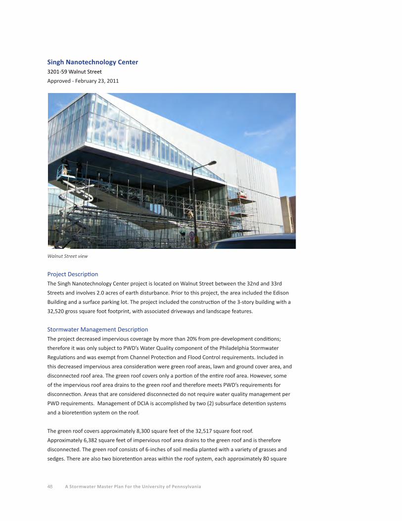
48 A Stormwater Master Plan For the University of Pennsylvania
Project DescriptionThe Singh Nanotechnology Center project is located on Walnut Street between the 32nd and 33rd
Streets and involves 2.0 acres of earth disturbance. Prior to this project, the area included the Edison
Building and a surface parking lot. The project included the construction of the 3-story building with a
32,520 gross square foot footprint, with associated driveways and landscape features.
Stormwater Management DescriptionThe project decreased impervious coverage by more than 20% from pre-development conditions;
therefore it was only subject to PWD’s Water Quality component of the Philadelphia Stormwater
Regulations and was exempt from Channel Protection and Flood Control requirements. Included in
this decreased impervious area consideration were green roof areas, lawn and ground cover area, and
disconnected roof area. The green roof covers only a portion of the entire roof area. However, some
of the impervious roof area drains to the green roof and therefore meets PWD’s requirements for
disconnection. Areas that are considered disconnected do not require water quality management per
PWD requirements. Management of DCIA is accomplished by two (2) subsurface detention systems
and a bioretention system on the roof.
The green roof covers approximately 8,300 square feet of the 32,517 square foot roof.
Approximately 6,382 square feet of impervious roof area drains to the green roof and is therefore
disconnected. The green roof consists of 6-inches of soil media planted with a variety of grasses and
sedges. There are also two bioretention areas within the roof system, each approximately 80 square
Singh Nanotechnology Center3201-59 Walnut Street
Approved - February 23, 2011
Walnut Street view

49Section 3 STORMWATER MANAGEMENT ON TODAY'S CAMPUS
Location map - Singh Nanotechnology Center
PROJECT BOUNDARY
EXISTING GREEN ROOF
EXISTING BIORETENTION AREA
EXISTING SUBSURFACE INFILTRATION/DETENTION
EXISTING GREEN SPACE
EXISTING TREE CREDITS
feet. These have a deeper soil media of 2.5 feet and tree plantings. These bioretention systems
manage a portion of DCIA from the roof. Runoff from impervious sections of the roof are conveyed and
uniformly distributed to the green roof areas via perforated piping.
There are two (2) subsurface detention systems that are utilized for stormwater management at the
site. The basins were designed as detention systems after it was determined that infiltration was
infeasible at this site due to high groundwater. Basin #1 is approximately 2,073 square feet in area and
is situated beneath the driveway to the east of the Nanotechnology building. Basin #2 is approximately
2,858 square feet in area and is situated beneath the triangular landscaped area to the south of the
building. Roof and ground surface runoff is collected by a series of roof drains, inlets, area drains, and
trench drains, which connect to pipes that convey the runoff separately to each basin. Intermediate
sump boxes are provided at the downstream ends of the conveyance piping system in order to settle
out debris and sediment prior to entering the detention basins. These units consist of concrete box
structures with 15-inch sumps and cast iron traps over the outlet pipes.
The basins consist of manufactured RainTank units wrapped in geotextile, and surrounded by a 3-24
inch layer of stone. RainTank units are open square crates made from 85% recycled polypropylene +
10% proprietary materials. These systems are modular systems and can be assembled to a variety of
shapes and heights. There are 12-inch diameter maintenance ports located near the center of each
system. Each basin connects to an outlet structure, which consists of a concrete box with a 6-inch thick
concrete weir wall that contains a 3-inch diameter orifice. The structures contain outlet pipes that are
protected by cast iron traps. Access to the interior of the structures is provided by manhole openings
on each side of the weir wall. The outlet pipes from the structures connect to the existing combined
sewer in Walnut Street.
• Green Roof: 8,300 sf
• Disconnected Roof: 3,985 sf
• Bioretention System management: 2,400 sf
• Subsurface Detention management: 49,071 sf
• Total Impervious area managed or disconnected: 63,756 sf
• Volume of runoff managed: 5,313 cubic feet
Hill HouseLSRM
BuildingNanotechnology Building Parking Garage Left Bank
Drexel University
Walnut Street
33rd
Str
eet
32nd
Str
eet

50 A Stormwater Master Plan For the University of Pennsylvania
Locust Walk3600, 3800 and 3900 Blocks of Locust Walk
Approved - May 2, 2011
3900 Block of Locust Walk view West
Project DescriptionThe Locust Walk project consists of the reconstruction of the 3600, 3800 and 3900 blocks of Locust
Walk. The project included pavement subbase repair and replacement. This area of Locust Walk, which
was formerly Locust Street, is included within the City’s Utility Right-of-Way; however the University
owns this section of the walk and is responsible for operation and maintenance of the surface
improvements. The project included the relocation of existing inlets and the installation of new inlets,
replacement of existing storm sewer piping, and the replacement of walkway surface.
Stormwater Management DescriptionIn order to meet PWD’s stormwater management requirements, the project utilized existing tree
canopy areas for credit. Although it is outside of the project area, PWD allowed the existing trees
along the 3600, 3800, and 3900 blocks of Locust Walk to be used toward tree credit for the project.
Areas that are considered disconnected do not require management per PWD requirements. The
project is disconnecting 95% or more of the post construction impervious area via credits from existing
trees. Therefore, this project does not include any SMPs for management beyond inlets and piping
for conveyance.
• Existing tree credit 3600 block: 12,749 sf
• Existing tree credit 3800 block: 6,487 sf
• Existing tree credit 3900 block: 9,787 sf
• Total Impervious area disconnected: 29,023 sf

51Section 3 STORMWATER MANAGEMENT ON TODAY'S CAMPUS
Location map - 3900 and 3800 Blocks of Locust Walk
PROJECT BOUNDARY
EXISTING GREEN SPACE
EXISTING TREE CREDITS
Location map - 3600 Block of Locust Walk 3900 Block of Locust Walk view East
3600 Block of Locust Walk view West
Free
Lib
rary Dubois College House
Rodin College House
St. Mary's Church
Gregory House
Civic House
Class of 1920 Commons
Steinhardt Hall
President's House
3808
-381
0 W
alnu
t
Kelly
Writ
ers
Hou
se
Harnwell
Fels Center
Alpha Tau
Omega
Sigma Chi W
orld
H
ouse
Walnut Street
38th
Str
eet
Annenberg CenterAnnenberg
Steinberg/Deitrich Hall
Locu
st
Hou
se
Colo
nial
Pe
nn
Del
ta P
si
Delta Phi Ph
i Gam
ma
Del
ta
Phi S
igm
a Ka
ppa
Addams Hall
APPC
The Arch
The Castle
Walnut Street
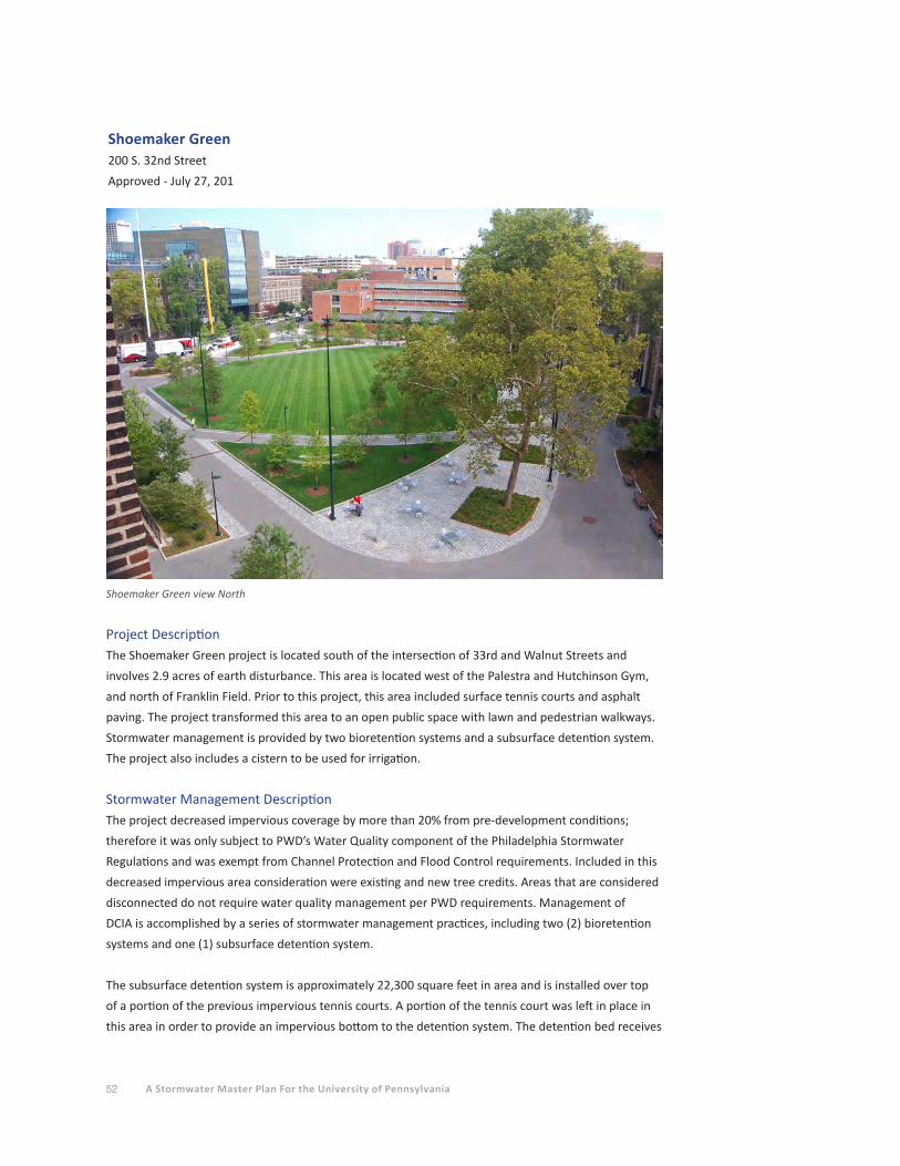
52 A Stormwater Master Plan For the University of Pennsylvania
Project DescriptionThe Shoemaker Green project is located south of the intersection of 33rd and Walnut Streets and
involves 2.9 acres of earth disturbance. This area is located west of the Palestra and Hutchinson Gym,
and north of Franklin Field. Prior to this project, this area included surface tennis courts and asphalt
paving. The project transformed this area to an open public space with lawn and pedestrian walkways.
Stormwater management is provided by two bioretention systems and a subsurface detention system.
The project also includes a cistern to be used for irrigation.
Stormwater Management DescriptionThe project decreased impervious coverage by more than 20% from pre-development conditions;
therefore it was only subject to PWD’s Water Quality component of the Philadelphia Stormwater
Regulations and was exempt from Channel Protection and Flood Control requirements. Included in this
decreased impervious area consideration were existing and new tree credits. Areas that are considered
disconnected do not require water quality management per PWD requirements. Management of
DCIA is accomplished by a series of stormwater management practices, including two (2) bioretention
systems and one (1) subsurface detention system.
The subsurface detention system is approximately 22,300 square feet in area and is installed over top
of a portion of the previous impervious tennis courts. A portion of the tennis court was left in place in
this area in order to provide an impervious bottom to the detention system. The detention bed receives
Shoemaker Green200 S. 32nd Street
Approved - July 27, 201
Shoemaker Green view North

53Section 3 STORMWATER MANAGEMENT ON TODAY'S CAMPUS
ground surface runoff via inlets and trench drains, which connect to a perforated distribution pipe
within the middle of a 12-inch thick stone layer, wrapped in non-woven geotextile fabric, located on
top of the tennis court. A 3-foot depth of planting soil is located above the stone. The system utilizes a
Smartdrain underdrain system that collects and slowly releases the stored water within the system. The
perforated distribution pipe is connected to a junction box which contains an overflow pipe that allows
larger storms to discharge from the system into the combined sewer located within the drive aisle to
the north of Franklin Field.
There is a bioretention system utilized for stormwater management at the site. Bioretention Area
BR-1 is approximately 1,642 square feet in area and is situated south of the southwest corner of the
David Rittenhouse Laboratories building, and just east of 33rd Street. This system receives ground
surface runoff via inlets and trench drains. Due to large fluctuations in tested infiltration rates, these
systems were not designed for infiltration. The bottom of the bioretention systems are lined with an
impervious liner. Smartdrains rest above the liner in a bed of sand to collect and slowly release stored
water within the system. A 2.5 foot layer of planting soil rests above the Smartdrain system. A mixture
of trees, shrubs, and grasses were planted within the bioretention systems. Overflow structures consist
of domed grate inlets and are set so that the ponding depths of these systems is approximately 8-10
inches. Overflows ultimately discharge to the combined sewer located within the drive aisle to the
north of Franklin Field.
The Smartdrain system utilized in both the subsurface detention system and the bioretention system
provides subsurface drainage and slow release of the stormwater stored within these systems. The
product is a device which is fitted with downward facing micro channels, which work by capillary
action and convey water at a slow rate. The micro channels are then connected to a collection pipe at a
downward angle creating a siphon action along the micro channels.
Location map - Shoemaker Green
PROJECT BOUNDARY
EXISTING POROUS PAVEMENT
EXISTING BIORETENTION AREA
EXISTING SUBSURFACE INFILTRATION/DETENTION
EXISTING GREEN SPACE
EXISTING TREE CREDITSFranklin Field
Palestra
Hutchinson Gym
Ringe Squash Courts
Shoemaker Green
Weightman Hall
Dunning
Hayden Hall
Towne Building
Levy Tennis
Pavilion
33rd
Stre
et

54 A Stormwater Master Plan For the University of Pennsylvania
Inlets contain water quality inserts manufactured by Suntree Technologies. These inserts consist
of a basket with different size filter screens which capture sediment and debris and which must be
periodically replaced.
The project also includes a 20,000 gallon concrete cistern for landscape irrigation. The cistern is an
additional feature for the project, as it was not considered in the design for compliance with the
Philadelphia Stormwater Regulations. The cistern is located to the east of Bioretention BR-1, below
the pedestrian pathway.
A concrete box with piping to the subsurface detention system has been provided adjacent to the
Hutchinson Gymnasium. The intent of this feature is to collect air conditioner condensate from the
building in the future.
• Tree Credit: 16,222 sf
• Subsurface detention management: 9,344 sf
• Bioretention BR-1: 13,161 sf
• Bioretention BR-2: 8,492 sf
• Total Impervious area managed or disconnected: 47,219 sf
• Total Impervious area within project limits that is not managed: 17,668 sf
• Volume of runoff managed: 3,935 cubic feet
Shoemaker Green Rain Garden
Shoemaker Green view North
Section 1 EXECUTIVE SUMMARY 55
Section 1 EXECUTIVE SUMMARY
Section 2 STORMWATER RUN-OFF FROM TODAY’S CAMPUS
Section 3 STORMWATER MANAGEMENT ON TODAY’S CAMPUS
Section 4 POTENTIAL STORMWATER MANAGEMENT PRACTICES FOR FUTURE PROJECTS
Section 5 FINDING SUSTAINABLE STORMWATER MANAGEMENT OPPORTUNITIES
Section 6 STORMWATER MANAGEMENT COSTS AND PWD FEES
Section 7 OPERATIONS AND MAINTENANCE CONSIDERATIONS
Section 8 LEGISLATION ISSUES AND FUNDING OPPORTUNITIES
Section 9 RECOMMENDATIONS
Section 10 APPENDICES
A. Representative Stormwater Management Details
B. Stormwater Management Model
C. References
D. Acknowledgementss

56 A Stormwater Master Plan For the University of Pennsylvania
POTENTIAL STORMWATER MANAGEMENT PRACTICES FOR FUTURE PROJECTS
Stormwater management technology continues to evolve as a result of increased regulatory requirements
and a desire to create sustainable solutions that attempt to restore the natural hydrologic cycle by
mimicking natural processes such as infiltration and bio-retention. Penn has already embraced some of
these storm water management practices (SMP’s) in the form of green roofs, bio-retention areas, and
porous pavements, as described in Section 3.
Stormwater management before the 1970’s focused mainly on collecting and conveying runoff off-site
in as efficient a manner as possible. This out-of-sight-out-of-mind tactic often resulted in the transfer of
drainage problems to unfortunate downstream property owners. In the 1970’s, a minor shift in emphasis
from drainage removal systems to safer conveyance of stormwater runoff peak discharges led to an
understanding of risks, predicting financial impacts, and attempts to control property damages caused
by stormwater. The 1990’s brought the era of focussing on surface water quality the initial stages of the
treatment component into stormwater management. At the beginning of the 21st century, concerns
regarding the depletion of fresh water supplies brought an emphasis to engineer systems that considered
runoff as a groundwater recharge resource rather than a wasted discharge.
This section identifies a number of innovative practices which Penn and its consultants may want to
consider as storm water management strategies for future development and redevelopment projects.
These contemporary practices include utilizing modular green building components, storm water
capture and reuse systems, green hardscape treatments, green streetscapes, bio-infiltration systems and
evapotranspiration components.
While a number of the described practices include specific products that are commercially available,
their mention in this document is not intended as endorsements of the products or their manufacturers.
Rather, the vendor/product information is provided to facilitate further research into new technologies
and their applicability to specific design projects.
Green RoofsA green roof system is an extension of the existing roof which involves a high quality water proofing
and root repellent system, a drainage system, filter cloth, a lightweight growing medium and plants.
Green roof systems may be modular, with drainage layers, filter cloth, growing media and plants already
prepared in movable, interlocking grids. Alternatively, each component of the system may be installed
separately. Green roof development involves the creation of "contained" green space on top of a human-
made structure. This green space could be below, at or above grade, but in all cases the plants are not
planted in the ground.
Green roofs can provide a wide range of public and private benefits. Green roofs manage storm water
by capturing rainfall in the growing medium of the roof system. Some of the rainfall is used by the
roof’s plants, some is evaporated from the soil, and excess water is gradually released from the growing
medium to drain to the roof’s downspout system.
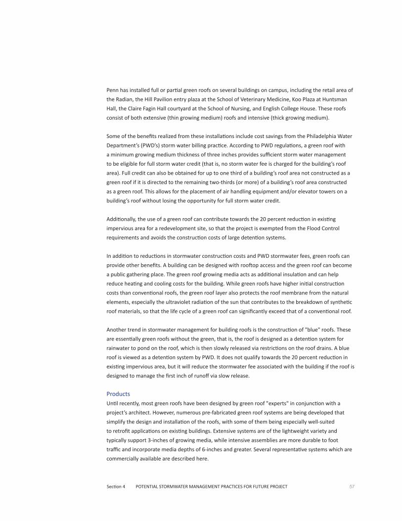
57Section 4 POTENTIAL STORMWATER MANAGEMENT PRACTICES FOR FUTURE PROJECT
Penn has installed full or partial green roofs on several buildings on campus, including the retail area of
the Radian, the Hill Pavilion entry plaza at the School of Veterinary Medicine, Koo Plaza at Huntsman
Hall, the Claire Fagin Hall courtyard at the School of Nursing, and English College House. These roofs
consist of both extensive (thin growing medium) roofs and intensive (thick growing medium).
Some of the benefits realized from these installations include cost savings from the Philadelphia Water
Department’s (PWD’s) storm water billing practice. According to PWD regulations, a green roof with
a minimum growing medium thickness of three inches provides sufficient storm water management
to be eligible for full storm water credit (that is, no storm water fee is charged for the building’s roof
area). Full credit can also be obtained for up to one third of a building’s roof area not constructed as a
green roof if it is directed to the remaining two-thirds (or more) of a building’s roof area constructed
as a green roof. This allows for the placement of air handling equipment and/or elevator towers on a
building’s roof without losing the opportunity for full storm water credit.
Additionally, the use of a green roof can contribute towards the 20 percent reduction in existing
impervious area for a redevelopment site, so that the project is exempted from the Flood Control
requirements and avoids the construction costs of large detention systems.
In addition to reductions in stormwater construction costs and PWD stormwater fees, green roofs can
provide other benefits. A building can be designed with rooftop access and the green roof can become
a public gathering place. The green roof growing media acts as additional insulation and can help
reduce heating and cooling costs for the building. While green roofs have higher initial construction
costs than conventional roofs, the green roof layer also protects the roof membrane from the natural
elements, especially the ultraviolet radiation of the sun that contributes to the breakdown of synthetic
roof materials, so that the life cycle of a green roof can significantly exceed that of a conventional roof.
Another trend in stormwater management for building roofs is the construction of "blue" roofs. These
are essentially green roofs without the green, that is, the roof is designed as a detention system for
rainwater to pond on the roof, which is then slowly released via restrictions on the roof drains. A blue
roof is viewed as a detention system by PWD. It does not qualify towards the 20 percent reduction in
existing impervious area, but it will reduce the stormwater fee associated with the building if the roof is
designed to manage the first inch of runoff via slow release.
ProductsUntil recently, most green roofs have been designed by green roof "experts" in conjunction with a
project’s architect. However, numerous pre-fabricated green roof systems are being developed that
simplify the design and installation of the roofs, with some of them being especially well-suited
to retrofit applications on existing buildings. Extensive systems are of the lightweight variety and
typically support 3-inches of growing media, while intensive assemblies are more durable to foot
traffic and incorporate media depths of 6-inches and greater. Several representative systems which are
commercially available are described here.
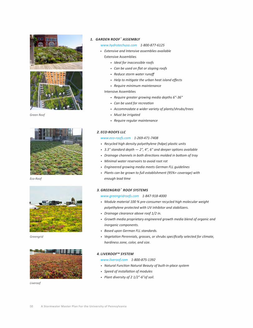
58 A Stormwater Master Plan For the University of Pennsylvania
1. GARDEN ROOF® ASSEMBLY
www.hydrotechusa.com 1-800-877-6125
• Extensive and Intensive assemblies available
Extensive Assemblies
• Ideal for inaccessible roofs
• Can be used on flat or sloping roofs
• Reduce storm water runoff
• Help to mitigate the urban heat island effects
• Require minimum maintenance
Intensive Assemblies
• Require greater growing media depths 6"-36"
• Can be used for recreation
• Accommodate a wider variety of plants/shrubs/trees
• Must be irrigated
• Require regular maintenance
2.ECO-ROOFSLLC
www.eco-roofs.com 1-269-471-7408
• Recycled high density polyethylene (hdpe) plastic units
• 3.3" standard depth — 2", 4", 6" and deeper options available
• Drainage channels in both directions molded in bottom of tray
• Minimal water reservoirs to avoid root rot
• Engineered growing media meets German FLL guidelines
• Plants can be grown to full establishment (95%+ coverage) with
enough lead time
3. GREENGRID® ROOF SYSTEMS
www.greengridroofs.com 1-847-918-4000
• Module material 100 % pre-consumer recycled high molecular weight
polyethylene protected with UV inhibitor and stabilizers.
• Drainage clearance above roof 1/2 in.
• Growth media proprietary engineered growth media blend of organic and
inorganic components.
• Based upon German FLL standards.
• Vegetation Perennials, grasses, or shrubs specifically selected for climate,
hardiness zone, color, and size.
4. LIVEROOF™ SYSTEM
www.liveroof.com 1-800-875-1392
• Natural Function Natural Beauty of built-in-place system
• Speed of installation of modules
• Plant diversity of 2 1/2"-6"of soil.
Green Roof
Eco-Roof
Greengrid
Liveroof

59Section 4 POTENTIAL STORMWATER MANAGEMENT PRACTICES FOR FUTURE PROJECT
5. TECTAGREEN™ MODULAR SYSTEMS
www.tectaamerica.com 1-866-832-8259
• A modular system can be assembled on-site
• Can be applied over the top of an already existing rooftop
• Complete with water retention fabric, 3.5" engineered growing media, and a
succulent mix of plants
• Designed to retain large amounts of water
6. AQUALOK™ SYSTEM
www.freedomgardenproducts.com 1-830-305-2299
• Lightweight – Well suited for existing structures and avoids costly structural
modifications
• Full-Time storm water detention system – water does not drain out through
soils other systems employ
• All the landscape options typically only available with 12" deep heavy soil
systems
• Thin profile avoids interference with mechanical equipment, perimeter roof
flashing, and accessible terraces.
• Significantly less components make for a quick, low-tech installation
• No soil to haul, place
• Ease of access to roof membrane to locate leaks
7. MUELLNER GREEN ROOF SYSTEM
www.resisolutions.com 1-763-784-0614
• Deep System allows for growth of a greater variety of turf and plants
• Supports normal lawn and recreational uses
• Provides both storm water control and plant irrigation
• Provides greater insulating properties
Applications1. NEW CONSTRUCTION
Advantages
• Ease of installation
• Warrantied products
• Interchangeable modules
• Numerous planting theme varieties
• Provide Heating/Cooling Benefits
• Provide Storm water Runoff Reductions
Disadvantages
• Additional capital investment
• Perishable construction item
• Not applicable to irregular shapes
• Installation may be in out of sight area
• Emergency snow removal labor intensive
Tectagreen
Aqualok
Muellner

60 A Stormwater Master Plan For the University of Pennsylvania
2.RETRO-FITTINGEXISTINGSTRUCTURES
Advantages
• Ease of installation
• Both flat and sloped roof applications
• Warrantied products
• Interchangeable modules
• Numerous planting theme varieties
• Provide Heating/Cooling Benefits
• Provide Storm water Runoff Reductions
Disadvantages
• Additional capital investment
• Perishable construction item
• Not applicable to irregular shapes
• Installation may be in out of sight area
• Emergency snow removal labor intensive
• Existing roof support structural analysis required
Green WallsGreen wall concepts have been in existence for centuries with examples in architecture dating back to
the ancient Babylonians, exemplified by one of the seven ancient wonders of the world, the Hanging
Gardens of Babylon. Many cultures trained grape vines to climb vertically, while manors and castles
displayed climbing roses on many building facades. Since the 1920s, features such as pergolas and a
variety of self-clinging climbing plants have been developed.
Typical green walls provide little opportunity for stormwater management and may in fact require
irrigation to sustain the vegetation. However, an intriguing application would be to use captured roof
stormwater runoff to irrigate the plants.
Self-clinging plants such as English Ivy have commonly been used to create green walls. Their sucker
root structure enables them to attach directly to a wall, covering entire surfaces. These aggressive
plants can damage unsuitable walls and make building maintenance and plant removal more difficult.
To reduce negative impacts to buildings, stainless steel cable and wire rope net structures have been
introduced into the marketplace over the last several decades and their use has become commonplace.
These systems allow for the plant material to thrive and expand vertically while remaining detached
from the building structure, thus reducing damage and maintenance concerns.
PWD's Stormwater Management Guidance Manual does not include green walls. However, stormwater
credit might be obtained by using captured rain water to irrigate a green wall inside a building.

61Section 4 POTENTIAL STORMWATER MANAGEMENT PRACTICES FOR FUTURE PROJECT
Products1. GREENSCREEN
www.greenscreen.com 1-800-450-3494
• Wall Mounted components
• Column applications
• Free Standing Screens
• Shade and Light Contral
• Graffiti Control
• Security partitions
2.ECO-MESH®MODULARPLANTTRELLIS
www.mcnichols.com 1-877-884-4653
• Enhances the appearance of structures and areas
• Hides unsightly equipment and unattractive building features
• Creates privacy screens using natural elements
• Cleans and cools air
• Helps to buffer wind and sound.
• Decreases energy consumption by regulating air temperature
Applications1. NEW CONSTRUCTION
Advantages
• Ease of installation
• Provides positive aura – supplements green building components
• Warrantied products
• Numerous planting theme varieties
• Provide Heating/Cooling Benefits
• Air Quality benefits
Disadvantages
• Additional capital investment
• Perishable construction item
2.RETRO-FITTINGEXISTINGSTRUCTURES
Advantages
• Ease of installation
• Can provide a "green" perception at lower cost to other green building
components
• Warrantied products
• Numerous planting theme varieties
• Provide Heating/Cooling Benefits
• Air Quality benefits
Disadvantages
• Additional capital investment
• Perishable construction item
Greenscreen
Eco-Mesh

62 A Stormwater Master Plan For the University of Pennsylvania
Capture and ReuseCapture and storage of rainwater for reuse at later times has been practiced for centuries. It is only in
the last few decades that this practice has been adopted in U.S. urban settings. Due to the low cost of
public water and the added cost of constructing a water treatment system and a secondary plumbing
system, the economics of this practice can be difficult to justify, especially as a retrofit practice to an
existing building or site. However, with new construction, the right combination of rainfall catchment
area and water demand may make the practice economically desirable and operationally feasible.
Capture/reuse systems can range from small rain barrels for garden watering to large surface cisterns
or subsurface tanks storing thousands of gallons of captured rainwater. The rainwater may be reused
for external uses such as landscaping or vehicle washing, or for internal building uses such as toilet
flushing, industrial process water, or fire protection.
For external non-potable uses, the rainwater may be able to be reused without any water quality
treatment prior to use. The Philadelphia Water Department (PWD) requires that storm water
management systems be completely drained within 72 hours of a rainfall event so that the system
capacity is fully available for a subsequent rainfall event. It should be noted that PWD does not
give storm water management credit for capture/reuse systems used for landscape irrigation. Since
irrigation will not occur during the winter months, there is no mechanism for draining the system within
72 hours. Also, within three days of a rain event, it may not be necessary to irrigate the landscape, so
the system will not be drained. However, automated systems have been developed that link real-time
weather forecasting with pump systems that will draw down the stored rainwater in anticipation of an
impending rainfall event. The pump system could be designed to meet the slow release requirements
of PWD’s storm water regulations, thereby making the system potentially eligible for stormwater credit.
For internal uses, some level of water quality treatment is typically required depending on the
proposed use of the captured rainwater. In addition to the added costs of a cistern and a water
treatment system, these internal systems typically require a parallel plumbing system so that water can
be provided from the public water system during periods when the cistern is empty. For the University,
these systems would be most practical in buildings that are occupied year-round, so that a constant
demand is available to draw down the captured rainwater volume. Administration buildings and
research facilities may be better suited for this technology than residential buildings or dining halls.
These systems are typically designed by a project’s mechanical/electrical/plumbing (MEP) engineer
in coordination with the project architect who helps establish anticipated water demands from the
building’s occupants. A number of simple models are publicly available to aid in the sizing of cisterns
based on local rainfall patterns; one such model is available online from North Carolina State University.
www.bae.ncsu.edu/topic/waterharvesting/model.html
63Section 4 POTENTIAL STORMWATER MANAGEMENT PRACTICES FOR FUTURE PROJECT
ProductsNumerous small rainbarrel products are available for the private homeowner. However, systems
suitable for use on large university buildings are typically designed by engineers using commercially
available storage tanks, pumps, and control devices.
Applications1. NEW CONSTRUCTION
Advantages
• Can reduce utility usage costs
• Potential storm water reduction credits
• Educational opportunities
Disadvantages
• Additional capital investment
• Additional infrastructure may be required for utilization
2.RETRO-FITTINGEXISTINGSTRUCTURES
Advantages
• Can reduce utility usage costs
• Potential storm water reduction credits
• Educational opportunities
Disadvantages
• Additional capital investment
• Additional infrastructure may be required for utilization
Green Hardscape Treatments (Porous Pavements)
Porous pavements have been in existence for almost 40 years. The first systems were installed in the
mid-1970’s and have been extensively monitored and evaluated. The major misconceptions regarding
porous pavement are that it easily clogs and offers no significant durability in either water permeability
or load carrying capacity. The extensive research conducted to date shows that in general, water
infiltration durability is a function of maintenance. The best performing systems in relation to water
permeability are those that were protected during the construction period of the project and biennially
swept by vacuum, while the most structurally durable systems are those installed in light duty traffic
areas such as parking lots, alleys, minor access drives and pedestrian areas.
Penn has constructed porous pavements on several projects on the campus; for example, porous
asphalt at Weiss Pavilion and a permeable paver system constructed for Woodland Walk, both of
which incorporate open joints between the paver units that allow for stormwater runoff to drain
through the walkway into a subsurface infiltration system below the pavement. Porous asphalt and
porous concretes can be ordered and delivered to most project sites from pre-mix plants, identical to
traditional asphalt and concrete ready-mix applications. Additionally, pre-manufactured products are
available and are becoming increasingly popular for paving and hardscape projects as discussed below:
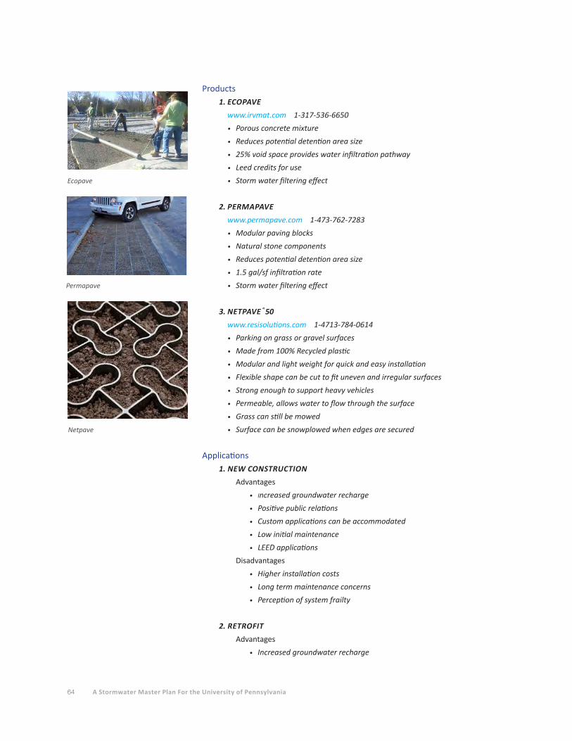
64 A Stormwater Master Plan For the University of Pennsylvania
Products1.ECOPAVE
www.irvmat.com 1-317-536-6650
• Porous concrete mixture
• Reduces potential detention area size
• 25% void space provides water infiltration pathway
• Leed credits for use
• Storm water filtering effect
2.PERMAPAVE
www.permapave.com 1-473-762-7283
• Modular paving blocks
• Natural stone components
• Reduces potential detention area size
• 1.5 gal/sf infiltration rate
• Storm water filtering effect
3.NETPAVE®50
www.resisolutions.com 1-4713-784-0614
• Parking on grass or gravel surfaces
• Made from 100% Recycled plastic
• Modular and light weight for quick and easy installation
• Flexible shape can be cut to fit uneven and irregular surfaces
• Strong enough to support heavy vehicles
• Permeable, allows water to flow through the surface
• Grass can still be mowed
• Surface can be snowplowed when edges are secured
Applications1. NEW CONSTRUCTION
Advantages
• Increased groundwater recharge
• Positive public relations
• Custom applications can be accommodated
• Low initial maintenance
• LEED applications
Disadvantages
• Higher installation costs
• Long term maintenance concerns
• Perception of system frailty
2. RETROFIT
Advantages
• Increased groundwater recharge
Ecopave
Permapave
Netpave

65Section 4 POTENTIAL STORMWATER MANAGEMENT PRACTICES FOR FUTURE PROJECT
• Positive public relations
• Custom applications can be accommodated (irregular shapes, difficult access)
• Low initial maintenance
• LEED applications
Disadvantages
• Demolition concerns
• Higher installation costs
• Long term maintenance concerns
• Perception of system frailty
• Why fix it if it wasn’t broke syndrome
Green StreetsGreen Streets is a concept that has evolved primarily due to the need to retrofit existing urbanized
areas in order to reduce impervious ground cover in hopes of reducing combined sewer overflows
(CSOs). Increased regulatory emphasis on CSOs has pressured utility operators to attain programmatic
goals of controlling the source of storm water, limiting its transport and pollutant conveyance to the
collection system, restoring predevelopment hydrology of drainage areas to the extent possible, and
providing environmentally enhanced roads. Realized benefits of these achieved goals have helped to
expand the green street concept beyond CSO problem areas and into many other urbanized locations.
Many communities across Europe, South America, and North America have taken the concept even
further by promoting community events centered on green street areas, temporarily closing down
streets to vehicular traffic and creating recreational park and festival-like atmospheres. Green Streets
implementation strategies encompass several best management practices, including bio-retention,
porous pavements, green canopies, and the use of vegetated drainage conveyance paths.
The Philadelphia Water Department (PWD) has begun a green streets initiative to foster design
guidelines and construction of demonstration projects on smaller alleyways and low-traffic streets.
Green streets principles could be applied to private driveways within the University campus.
Opportunities may exist for the University and PWD to collaborate on converting an existing city
street running through the campus into a green street. Such a project might include directing clean
stormwater runoff from University building roofs to stormwater management systems located within
the city street’s right-of-way and cost-sharing between the university and the city for construction
and maintenance.
Bioretention ProductsBio-retention is accomplished through the strategic location of small scale engineered eco-systems
designed to retain certain amounts of storm water through the natural absorption and transpiration
qualities of plants and soil structures. Many natural processes occur within bio-retention cells:
infiltration and storage reduces runoff volumes and attenuates peak flows; water-purifying biological
and chemical reactions occur in the mulch, soil matrix, and root zone; and storm water is filtered
through vegetation and soil. Excess runoff is typically managed via an overflow outlet that drains to an
underground detention system or directly to the public sewer system.
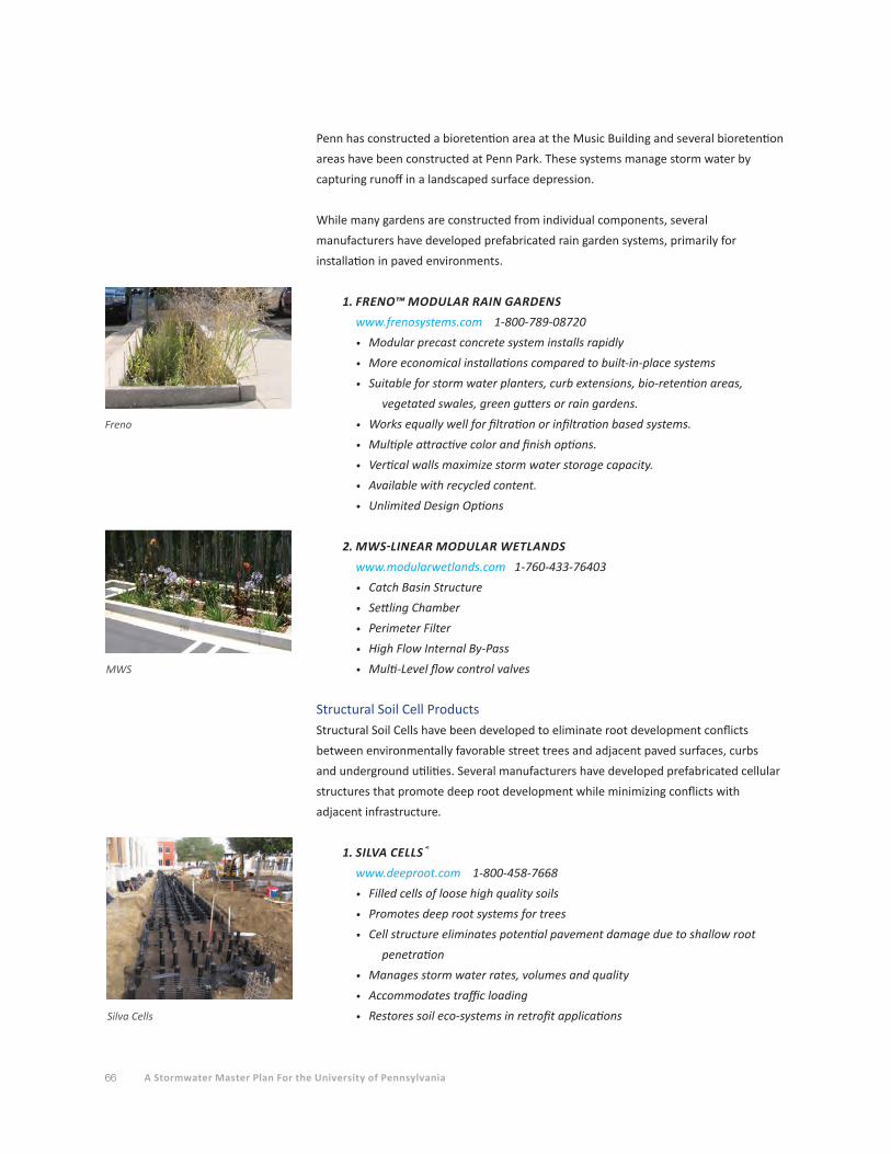
66 A Stormwater Master Plan For the University of Pennsylvania
Penn has constructed a bioretention area at the Music Building and several bioretention
areas have been constructed at Penn Park. These systems manage storm water by
capturing runoff in a landscaped surface depression.
While many gardens are constructed from individual components, several
manufacturers have developed prefabricated rain garden systems, primarily for
installation in paved environments.
1. FRENO™ MODULAR RAIN GARDENS
www.frenosystems.com 1-800-789-08720
• Modular precast concrete system installs rapidly
• More economical installations compared to built-in-place systems
• Suitable for storm water planters, curb extensions, bio-retention areas,
vegetated swales, green gutters or rain gardens.
• Works equally well for filtration or infiltration based systems.
• Multiple attractive color and finish options.
• Vertical walls maximize storm water storage capacity.
• Available with recycled content.
• Unlimited Design Options
2.MWS-LINEARMODULARWETLANDS
www.modularwetlands.com 1-760-433-76403
• Catch Basin Structure
• Settling Chamber
• Perimeter Filter
• High Flow Internal By-Pass
• Multi-Level flow control valves
Structural Soil Cell ProductsStructural Soil Cells have been developed to eliminate root development conflicts
between environmentally favorable street trees and adjacent paved surfaces, curbs
and underground utilities. Several manufacturers have developed prefabricated cellular
structures that promote deep root development while minimizing conflicts with
adjacent infrastructure.
1. SILVA CELLS®
www.deeproot.com 1-800-458-7668
• Filled cells of loose high quality soils
• Promotes deep root systems for trees
• Cell structure eliminates potential pavement damage due to shallow root
penetration
• Manages storm water rates, volumes and quality
• Accommodates traffic loading
• Restores soil eco-systems in retrofit applications
Freno
MWS
Silva Cells
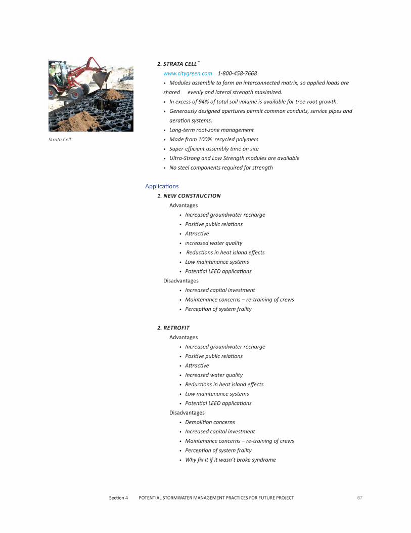
67Section 4 POTENTIAL STORMWATER MANAGEMENT PRACTICES FOR FUTURE PROJECT
2. STRATA CELL®
www.citygreen.com 1-800-458-7668
• Modules assemble to form an interconnected matrix, so applied loads are
shared evenly and lateral strength maximized.
• In excess of 94% of total soil volume is available for tree-root growth.
• Generously designed apertures permit common conduits, service pipes and
aeration systems.
• Long-term root-zone management
• Made from 100% recycled polymers
• Super-efficient assembly time on site
• Ultra-Strong and Low Strength modules are available
• No steel components required for strength
Applications1. NEW CONSTRUCTION
Advantages
• Increased groundwater recharge
• Positive public relations
• Attractive
• Increased water quality
• Reductions in heat island effects
• Low maintenance systems
• Potential LEED applications
Disadvantages
• Increased capital investment
• Maintenance concerns – re-training of crews
• Perception of system frailty
2. RETROFIT
Advantages
• Increased groundwater recharge
• Positive public relations
• Attractive
• Increased water quality
• Reductions in heat island effects
• Low maintenance systems
• Potential LEED applications
Disadvantages
• Demolition concerns
• Increased capital investment
• Maintenance concerns – re-training of crews
• Perception of system frailty
• Why fix it if it wasn’t broke syndrome
Strata Cell
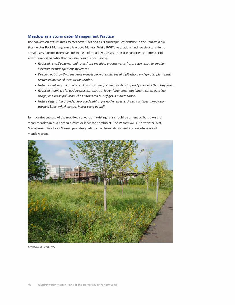
68 A Stormwater Master Plan For the University of Pennsylvania
Meadow as a Stormwater Management PracticeThe conversion of turf areas to meadow is defined as "Landscape Restoration" in the Pennsylvania
Stormwater Best Management Practices Manual. While PWD’s regulations and fee structure do not
provide any specific incentives for the use of meadow grasses, their use can provide a number of
environmental benefits that can also result in cost savings:
• Reduced runoff volumes and rates from meadow grasses vs. turf grass can result in smaller
stormwater management structures.
• Deeper root growth of meadow grasses promotes increased infiltration, and greater plant mass
results in increased evapotranspiration.
• Native meadow grasses require less irrigation, fertilizer, herbicides, and pesticides than turf grass.
• Reduced mowing of meadow grasses results in lower labor costs, equipment costs, gasoline
usage, and noise pollution when compared to turf grass maintenance.
• Native vegetation provides improved habitat for native insects. A healthy insect population
attracts birds, which control insect pests as well.
To maximize success of the meadow conversion, existing soils should be amended based on the
recommendation of a horticulturalist or landscape architect. The Pennsylvania Stormwater Best
Management Practices Manual provides guidance on the establishment and maintenance of
meadow areas.
Meadow in Penn Park

Section 1 EXECUTIVE SUMMARY 69
Section 1 EXECUTIVE SUMMARY
Section 2 STORMWATER RUN-OFF FROM TODAY’S CAMPUS
Section 3 STORMWATER MANAGEMENT ON TODAY’S CAMPUS
Section 4 POTENTIAL STORMWATER MANAGEMENT PRACTICES FOR FUTURE PROJECTS
Section 5 FINDING SUSTAINABLE STORMWATER MANAGEMENT OPPORTUNITIES
Section 6 STORMWATER MANAGEMENT COSTS AND PWD FEES
Section 7 OPERATIONS AND MAINTENANCE CONSIDERATIONS
Section 8 LEGISLATION ISSUES AND FUNDING OPPORTUNITIES
Section 9 RECOMMENDATIONS
Section 10 APPENDICES
A. Representative Stormwater Management Details
B. Stormwater Management Model
C. References
D. Acknowledgements
70 A Stormwater Master Plan For the University of Pennsylvania
FINDING SUSTAINABLE STORMWATER MANAGEMENT OPPORTUNITIES
This section provides the block-by-block analysis of the campus, identifying potential opportunities
for stormwater retrofitting, shared stormwater management facilities, and possible options for future
construction of facilities described in the Penn Connects and Penn Connects 2.0 studies. The intent of
this distributed approach is to manage rainfall where it falls, rather than concentrating and conveying
it via pipes to other locations. For new construction projects, the PWD regulations require that the first
inch of runoff from impervious surfaces be infiltrated. However, whether this requirement can be met
is determined by the soils existing at the proposed site.
Infiltration and Campus SoilsAccording to the U.S. Department of Agriculture’s Natural Resources Conservation Service Soil Survey,
100 percent of the campus study area consists of Urban Land (Ub) soils. The characteristics of these
soils are highly variable and may consist of severely disturbed original soils or imported urban fill of
varying composition. Infiltration rates for urban soils can vary widely, from very low due to compaction
or fine clay/ash content to very high due to past use of rubble as fill or the presence of large subsurface
voids resulting from prior building demolitions.
Due to this high degree of variability, PWD requires that infiltration testing be conducted on all
proposed construction sites (that exceed 15,000 square feet in disturbance and must therefore comply
with the stormwater regulations). Ideally, this testing is performed using a double-ring infiltrometer, in
a test intended to represent the infiltration process occurring at the base of an infiltration system. The
testing must be completed within the area of the proposed infiltration facility, and at a depth matching
the proposed bottom of the system.
To meet PWD’s requirements, infiltration test rates must fall within the range of 0.5 to 10 inches per
hour. Rates below 0.5 inches per hour may not allow a system to drain within the required 72 hours,
and may indicate an already dense soil that will be more prone to clogging of the underlying soil pores,
resulting in a premature failure of the infiltration system. Rates above 10 inches per hour may indicate
excessive voids in the underlying soil structure which may become unstable with the introduction of
infiltrated stormwater. PWD will allow infiltration on sites with test rates above 10 inches per hour but
will require soil amendments or compaction methods to lower the infiltration rate.
To reduce the potential for problems with the structural integrity of building foundations and the
inflow of infiltrated stormwater into building basements, PWD requires that infiltration systems be
located at least 10 feet downgradient and 100 feet upgradient of existing or proposed structures. To
reduce the potential for problems on adjoining properties, infiltration systems must be located at least
10 feet from property lines.
If the infiltration capacity of a construction site’s soils does not meet PWD’s requirements, then the
first inch of runoff from impervious surfaces must be captured in surface or subsurface detention
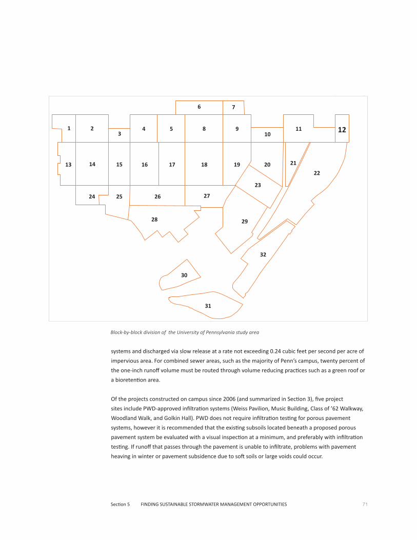
71Section 5 FINDING SUSTAINABLE STORMWATER MANAGEMENT OPPORTUNITIES
systems and discharged via slow release at a rate not exceeding 0.24 cubic feet per second per acre of
impervious area. For combined sewer areas, such as the majority of Penn’s campus, twenty percent of
the one-inch runoff volume must be routed through volume reducing practices such as a green roof or
a bioretention area.
Of the projects constructed on campus since 2006 (and summarized in Section 3), five project
sites include PWD-approved infiltration systems (Weiss Pavilion, Music Building, Class of ’62 Walkway,
Woodland Walk, and Golkin Hall). PWD does not require infiltration testing for porous pavement
systems, however it is recommended that the existing subsoils located beneath a proposed porous
pavement system be evaluated with a visual inspection at a minimum, and preferably with infiltration
testing. If runoff that passes through the pavement is unable to infiltrate, problems with pavement
heaving in winter or pavement subsidence due to soft soils or large voids could occur.
Block-by-block division of the University of Pennsylvania study area
WALL
1 4 5 8 9 113 10
12
6 7
13 14 15 16 17 18 19 20 21
22
26 27
23
28 29
30
31
32
24 25
2
72 A Stormwater Master Plan For the University of Pennsylvania
Trading and Banking of Impervious Areas and Stormwater ManagementBefore outlining the procedural framework for stormwater management, the concepts of "trading" and
"banking" should be defined. PWD supports this approach on large multi-building parcels such as college
campuses or business parks. As an example of "trading", suppose the University proposes construction
of a new building but is not able to provide stormwater management for the structure due to space
limitations or because a green roof is not feasible for the proposed building. To meet the required
stormwater management, the University could retrofit an existing impervious area on the same block or
within several blocks from the project. An existing building might be retrofitted with a green roof of the
same area as the proposed unmanaged building, or an existing parking lot might be converted to
porous pavement such that the new pavement area matches the area of the proposed building.
Under this scenario, the University has not advanced its overall net campus runoff as a result of the
proposed construction.
As an example of "banking", suppose the University has two projects planned within the same block
or within a few blocks of each other: one project is a new building and the second project is the
reconstruction of a large existing parking area as part of a scheduled repaving operation. To provide
the stormwater management for the new building, the University proposes to "trade" impervious area
by reconstructing a portion of the existing parking area as porous pavement, with an area of porous
pavement equal to the new building’s impervious area. However, the University can take the project
to the next "banking" level by repaving additional areas of the existing lot with porous pavement. This
pavement area now exceeds the PWD stormwater management requirements and can be "banked" for
future construction projects, e.g. other new buildings or parking areas in the vicinity of the project.
These trading/banking projects need to be fully vetted with PWD. Typically, PWD wants the various
sites of a trading/banking project to be located within the same sewershed so that the projects result
in no net increase to any specific sewer. Also, PWD may place restrictions on how long the additional
stormwater management may be banked.
A Procedural Framework for Stormwater Planning on a Block-by-Block Basis The information provided in the block-by-block diagrams in this section can be used in a phased
approach to stormwater planning for new or retrofit construction projects. This approach considers
existing site and utility constraints and opportunities for shared stormwater management facilities. In
addition to frameworks for new and retrofit projects, a separate approach is provided for potential green
street projects.
New Construction1. Identify project requirements - Prepare the conceptual layout of the site including the building
footprint, parking requirements, and pedestrian walkways. Identify potential locations for
ground-level stormwater management facilities adjacent to the proposed building or structure.
2. Review planned construction on adjoining blocks - Using the block-by-block diagrams,
identify new projects and potential retrofit projects across the streets from the proposed
new construction. These adjoining projects may include repaving of existing parking areas,
reconstruction of existing sidewalks, or repair/replacement of roofs on existing buildings.
73Section 5 FINDING SUSTAINABLE STORMWATER MANAGEMENT OPPORTUNITIES
3. Identify existing utilities in the streets surrounding the proposed new construction - determine
if existing utilities propose obstacles to cross-street transfer of stormwater runoff via
underground pipes.
4. Consider "banking/trading" options - In the event that existing utilities prevent the
conveyance of stormwater across adjoining streets, the University might also consider
"banking" or "trading" impervious area as described above. Using the block-by-block
diagrams, identify multiple projects in one area that might "trade" impervious areas to meet
PWD requirements, or consider construction of surplus stormwater management capacity to
be applied towards a future project.
5. Identify existing utilities within the block of the proposed construction - Locate all existing
utilities in the vicinity of the proposed construction to ensure there are no conflicts with the
proposed building or potential stormwater management locations.
6. Identify shared facility options - Shared facilities are limited to surface or subsurface systems,
such as surface bioretention areas located in open green areas or subsurface infiltration/
detention systems located beneath parking areas. If such a system is to be constructed as
part of a new construction project, consider overdesign of the system volume to allow for
management of runoff from adjacent existing buildings or paved areas. Using the block-by-
block diagrams as a guide, determine the feasibility of connecting roof drains or storm inlets
from these existing facilities to the new shared facility.
7. Identify green roof potential for new and existing buildings - Constructing the new building
with a green roof will reduce the size of ground-level stormwater management facilities. It
may also help the project achieve the 20 percent reduction in existing impervious area that
exempts a project from the costly Flood Control requirement. Depending on the green roof
system employed, there may be reduced unit costs if adjacent existing buildings are retrofitted
with green roofs at the same time. Use the block-by-block diagrams to identify potential
green roof retrofits in the vicinity of the proposed project.
8. Conduct infiltration testing - At this point, a project has moved from the stormwater planning
stages to the preliminary engineering stage. A determination of the feasibility for infiltration
on the project site will further refine the list of stormwater management options, e.g. whether
or not porous pavement will work.
9. Prepare conceptual stormwater design - With an understanding of the infiltration potential
for a given site, the conceptual stormwater approach can be preliminarily designed. With this
information, cost estimates can be generated that evaluate construction costs vs. reductions
in PWD stormwater fees. Decisions can be made regarding the extent to which additional
retrofitting or shared facilities are constructed. Section 6 of the master plan discusses
stormwater construction costs and the PWD fees in greater detail.
Retrofit ProjectsPlanning for retrofit construction projects follows a similar step-by-step approach as new construction.
However, if a retrofit project is being considered only as a stand-alone project, the retrofitting should
be considered as a part of the scheduled maintenance of the existing facility.
When an existing building roof requires repair or is scheduled for replacement, a green roof retrofit
should be considered. The green roof retrofit construction cost may exceed that of conventional

74 A Stormwater Master Plan For the University of Pennsylvania
74
repair or replacement, but the increased cost will be offset by the reduction of the monthly PWD
stormwater fee (over the life of the building).
If an existing parking area or pedestrian walkway/plaza is scheduled for repaving or reconstruction,
consider the use of porous pavement. Again, the retrofit cost may exceed the cost of conventional
replacement, but the increased cost will be offset by the reduction of the PWD fee. The
construction cost vs. PWD fee offset is discussed in greater detail in Section 6.
Green Streets – Opportunities for Public/Private Shared FacilitiesCity streets and sidewalks account for approximately 38 percent of the impervious area located
within the City’s combined sewer service area. Recognizing the significant runoff volume that these
surfaces contribute to the combined sewer overflow problem, PWD has instituted a green streets
initiative aimed at reducing street runoff. While PWD’s primary interest in green streets is from a
stormwater management perspective, a more holistic concept is that of "complete streets." This
term refers to creating a streetscape environment that places the needs of the pedestrian ahead of
the needs of the motor vehicle occupant.
The "complete street" encourages pedestrian and bicycle use, improves the quality of life by
providing a safe and aesthetically pleasing environment, and provides stormwater management
and increased green space which improves air quality and reduces the urban heat island effect.
Typically, existing parking spaces near intersections are converted into vegetated stormwater
management areas that protrude into the former parking lane. These "bump outs" or "curb
extensions" have the effect of calming (i.e., slowing) traffic at intersections, exactly where most
pedestrian-bicycle-motor vehicle conflicts may occur. The result is a safer, greener experience for
the pedestrian and bicyclist.
Often, the primary obstacle to creating a green street is the number and complexity of existing
utilities located within the street right-of-way. The utilities may interfere with the preferred
placement of bioretention areas, tree trenches located in the sidewalk area that accept street and
sidewalk runoff, or underground infiltration/detention facilities. As a result, open areas on private
property adjacent to the street right-of-way may provide more opportunities for stormwater
management system placement.
However, stormwater runoff from streets may be contaminated with gas, oil, antifreeze, battery
acid, and heavy metals and other pollutants from internal combustion as well as tire and brake
wear. The University may have liability concerns about introducing these contaminants onto their
private property. In the worst case, a gasoline spill from a vehicle accident could quickly find its
way into the street drainage system that leads to an infiltration/detention facility located on Penn’s
private property. Such contamination could lead to costly remediation, possibly including the
complete removal of the stormwater system and remediation of the underlying contaminated soils.
Because input from PWD and the City Department of Streets would be required in the design of
a green street on Penn’s campus, analysis of green street potential on a street-by-street basis is
beyond the scope of this master plan.

75Section 5 FINDING SUSTAINABLE STORMWATER MANAGEMENT OPPORTUNITIES
The Block-by-Block AnalysisThe campus was divided into "32 blocks" in order to evaluate stormwater management opportunities
on a smaller, more detailed scale. The City streets were typically used to define the extents of the
blocks, however there may be locations where cross-block transfer of stormwater runoff is feasible. An
AutoCAD drawing of the campus and aerial photography were used to evaluate the blocks for different
types of stormwater management practices.
Using aerial photography and three-dimensional building representations from Google Earth, the
Penn-owned buildings were evaluated for their potential for green roof retrofitting. Existing roofs were
not considered viable for green roof retrofitting if the roof is pitched, if there is extensive mechanical
equipment or towers on the roof, or if there are numerous roof areas at varying levels. Tray-type green
roof systems may be feasible in the latter two conditions, but the focus of the evaluation was large,
flat roof areas presenting few obstacles to green roof installation and maintenance. An analysis of
the existing buildings’ structural capacities to support retrofitted green roofs was not completed, nor
were any on-site roof inspections undertaken. Both would be important next steps in the procedural
planning framework outlined above.
Ground-level open areas were evaluated for their potential for porous pavement conversion,
bioretention areas, and subsurface infiltration/detention systems. Detailed sizing of the systems was
not performed. The maximum available open space is delineated in the block-by-block graphics and
should be evaluated for existing utility conflicts as well as future development plans for the open areas.
The feasibility of infiltration based on soil characteristics was not considered in the evaluation. In the
event that the soils of an open area are infeasible for infiltration, underdrained bioretention areas or
standard impervious asphalt/concrete pavements with subsurface stormwater management facilities
could be employed.
Existing walkways and other paved areas were evaluated for their potential for pavement
disconnection. If a paved area up to 75 feet wide drains via sheet flow to a vegetated area of equal
or greater width and with less than a 5 percent slope, PWD considers this pavement disconnected.
Stormwater management is not required for the disconnected pavement and the area can contribute
towards the 20 percent reduction in existing impervious area which exempts a project from the costly
Flood Control requirement. Disconnected pavement areas are exempt from the PWD stormwater fees.
Existing trees were evaluated for their disconnection credit. Existing trees located within twenty feet
of paved areas are eligible for the disconnection credit. Fifty percent of the canopy area of the existing
tree can contribute towards the 20 percent reduction in existing impervious area. The PWD stormwater
fee can be reduced based on the canopy area that covers existing ground-level impervious area. New
trees can also contribute to both the 20 percent reduction and PWD fee reductions, but potential new
tree locations are not shown on the block-by-block diagrams.
All areas listed in the graphics should be considered approximate and will require further detailed
analysis to determine feasibility.
Prior to the block-by-block diagrams, the following pages depict the various potential and existing
stormwater BMP features on a campus-wide basis, to provide a general illustration of the distribution
of the features across the campus.
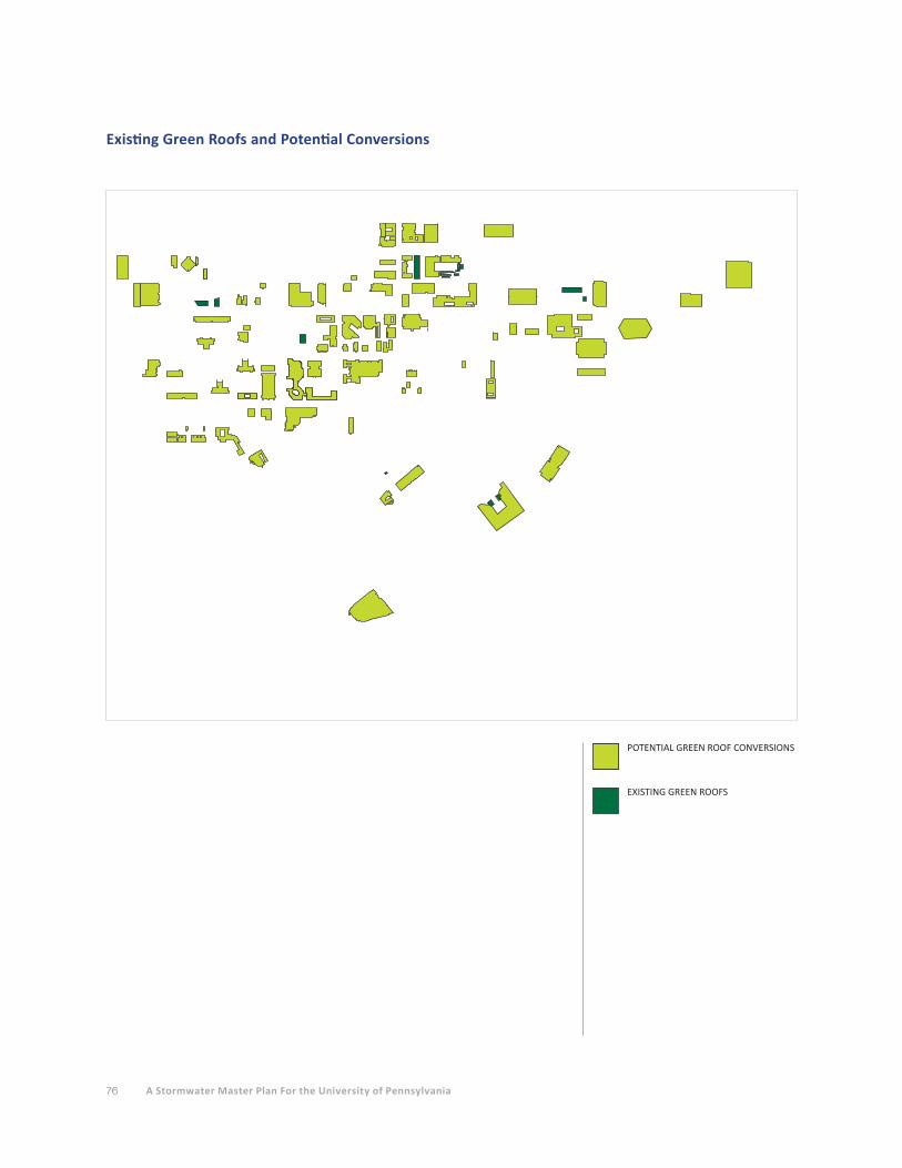
76 A Stormwater Master Plan For the University of Pennsylvania
WALL
Existing Green Roofs and Potential Conversions
POTENTIAL GREEN ROOF CONVERSIONS
EXISTING GREEN ROOFS
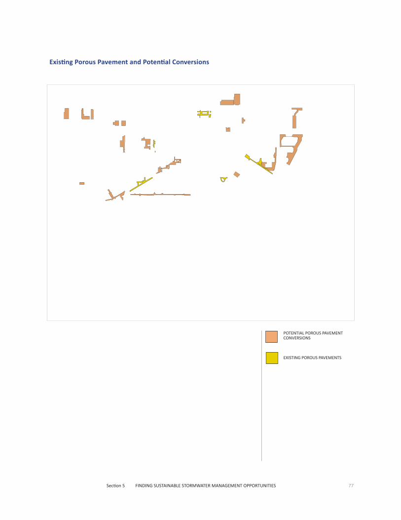
77Section 5 FINDING SUSTAINABLE STORMWATER MANAGEMENT OPPORTUNITIES
WALL
Existing Porous Pavement and Potential Conversions
POTENTIAL POROUS PAVEMENT CONVERSIONS
EXISTING POROUS PAVEMENTS
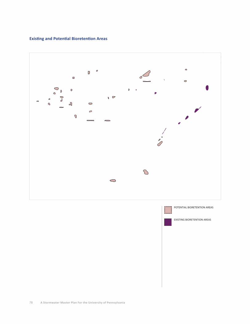
78 A Stormwater Master Plan For the University of Pennsylvania
WALL
Existing and Potential Bioretention Areas
POTENTIAL BIORETENTION AREAS
EXISTING BIORETENTION AREAS

79Section 5 FINDING SUSTAINABLE STORMWATER MANAGEMENT OPPORTUNITIES
WALL
Existing and Potential Subsurface Infiltration/Detention Systems
POTENTIAL SUBSURFACE INFILTRATION/DETENTION SYSTEMS
EXISTING SUBSURFACE INFILTRATION/DETENTION SYSTEMS
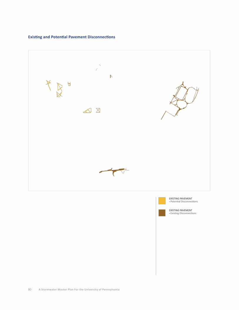
80 A Stormwater Master Plan For the University of Pennsylvania
WALL
Existing and Potential Pavement Disconnections
EXISTING PAVEMENT • Potential Disconnections
EXISTING PAVEMENT• Existing Disconnections
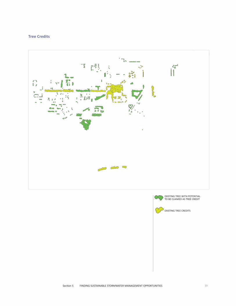
81Section 5 FINDING SUSTAINABLE STORMWATER MANAGEMENT OPPORTUNITIES
Tree Credits
WALL
EXISTING TREE WITH POTENTIAL TO BE CLAIMED AS TREE CREDIT
EXISTING TREE CREDITS
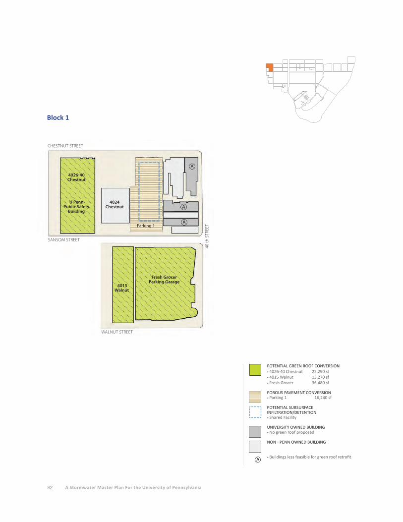
82 A Stormwater Master Plan For the University of Pennsylvania
Block 1
SANSOM STREET
CHESTNUT STREET
40 th
STR
EET
4026-40 Chestnut
U Penn Public Safety
Building
Fresh Grocer
Parking Garage
Parking 1
4024 Chestnut
WALNUT STREET
A
A
A
4015 Walnut
POTENTIAL GREEN ROOF CONVERSION • 4026-40 Chestnut 22,290 sf• 4015 Walnut 13,270 sf• Fresh Grocer 36,480 sf
POROUS PAVEMENT CONVERSION• Parking 1 16,240 sf POTENTIAL SUBSURFACE INFILTRATION/DETENTION• Shared Facility
UNIVERSITY OWNED BUILDING• No green roof proposed
NON - PENN OWNED BUILDING
• Buildings less feasible for green roof retrofitA

83Section 5 FINDING SUSTAINABLE STORMWATER MANAGEMENT OPPORTUNITIES
Block 2
POTENTIAL SUBSURFACE INFILTRATION/DETENTION• To manage pavement and rooftop run-off
PENN CONNECTS/POTENTIAL DEVELOPMENT• Potential green roof
UNIVERSITY OWNED BUILDING• No green roof proposed
NON - PENN OWNED BUILDING
• Buildings less feasible for green roof retrofitA
POTENTIAL GREEN ROOF CONVERSION • 3948 Chestnut 5,420 sf• University City District 5,900 sf• HUP Offices 10,150 sf• 3910 Chestnut 2,000 sf• 3935 Sansom 2,290 sf• 3929 Sansom 5,620 sf• Chestnut Hall 26,200 sf
EXISTING GREEN ROOF • Radian 11,010 sf
POROUS PAVEMENT CONVERSION• Parking 1 15,970 sf• Parking 2 9,700 sf
POTENTIAL SUBSURFACE INFILTRATION/DETENTION• To manage pavement and rooftop run-off
HUP Offices
Chestnut Hall
Radian
Campus Copy
Center
McD
onal
d’s
St. James Church
3933
3929
Parking 1
Park
ing
2
Park
ing39
10
ATA
3935
San
som
3929
San
som
3912 - 3938 Sansom
Uni
vers
ity
City
D
istr
ict
3948
Che
stnu
t
SANSOM STREET
CHESTNUT STREET
WALNUT STREET
39 th
STR
EET
A
A12
2 - 1
28
39th
Str
eet
A
40 th
STR
EET
Potential Development
Parcel
Prop
osed
M
ixed
-use
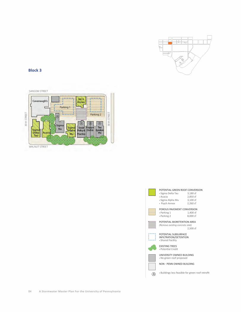
84 A Stormwater Master Plan For the University of Pennsylvania
Block 3
SANSOM STREET
WALNUT STREET
38 th
STR
EET
Parking 1
Cavanaugh’s
Parking 2
Sigma Delta Tau
Acacia
Sigma Alpha
Mu
3815 Annex
Sigma Nu Social
Policy & Practice
KappaDelta
TauEpisilon
Phi
A A A
A
39 th
STR
EET
POTENTIAL GREEN ROOF CONVERSION • Sigma Delta Tau 3,180 sf• Acacia 2,850 sf• Sigma Alpha Mu 3,100 sf• Psych Annex 2,260 sf
POROUS PAVEMENT CONVERSION• Parking 1 1,400 sf• Parking 2 8,000 sf
POTENTIAL BIORETENTION AREA(Remove existing concrete slab) 2,500 sf
POTENTIAL SUBSURFACE INFILTRATION/DETENTION• Shared Facility
EXISTING TREES • Potential Credit
UNIVERSITY OWNED BUILDING• No green roof proposed
NON - PENN OWNED BUILDING
• Buildings less feasible for green roof retrofitA

85Section 5 FINDING SUSTAINABLE STORMWATER MANAGEMENT OPPORTUNITIES
Block 4
SANSOM STREET
WALNUT STREET
CHESTNUT STREET
38 th
STR
EET
37 th
STR
EET
Module 6Retail/Garage
PottruckFitnessCenter
Gimbel Gym
St. AgathaSt. James
ChurchNewman
Center
TabernacleChurchG
reen
field
Ctr
.
Rect
ory
3779 Sansom
A A
POTENTIAL GREEN ROOF CONVERSION • Pottruck 13,200 sf• Module 6 34,900 sf
(Convert upper level of Module 6 to partial green roof. Loss of approximately 84 parking spaces.)
POTENTIAL BIORETENTION AREA• In exsiting grass area
POTENTIAL SUBSURFACE INFILTRATION/DETENTION• Shared Facility
EXISTING GREEN SPACE
EXISTING TREE • Potential Credit
EXISTING PAVEMENT • Potential Disconnection Credit
UNIVERSITY OWNED BUILDING• No green roof proposed
NON - PENN OWNED BUILDING
• Buildings less feasible for green roof retrofitA

86 A Stormwater Master Plan For the University of Pennsylvania
Block 5
SANSOM STREET
WALNUT STREET
ICA
Sansom Place East
Sansom Place West
U of P Bookstore
Inn at Penn
Retail 1 Retail 2
CHESTNUT STREET
A
A
A
36 th
STR
EET
37 th
STR
EET
POTENTIAL GREEN ROOF CONVERSION• Sansom Place West 2,420 sf • Sansom Place East 5,600 sf• ICA 12,700 sf• Retail 1 5,380 sf• Retail 2 15,510 sf
EXISTING GREEN ROOF
POTENTIAL BIORETENTION AREA• To manage parking lot
POTENTIAL SUBSURFACE INFILTRATION/DETENTION• To manage pavement/roof
EXISTING GREEN SPACE
EXISTING TREE • Potential Credit
EXISTING PAVEMENT • Potential Disconnection Credit
UNIVERSITY OWNED BUILDING• No green roof proposed
• Buildings less feasible for green roof retrofitA
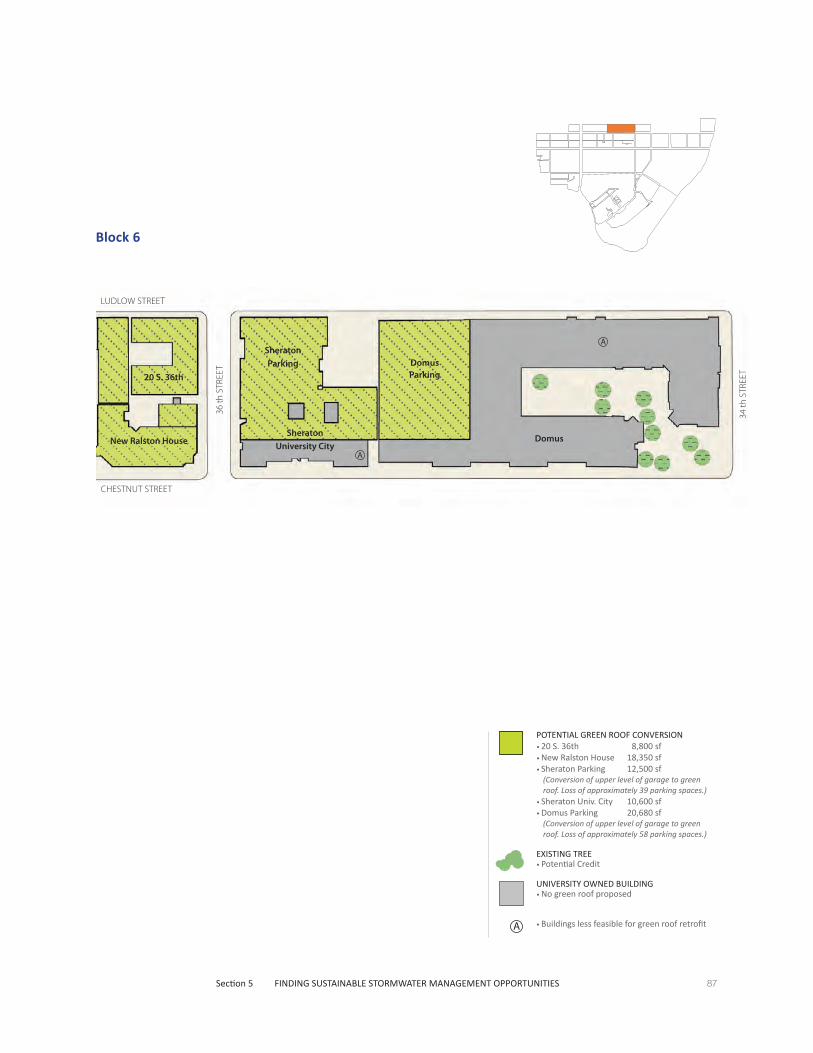
87Section 5 FINDING SUSTAINABLE STORMWATER MANAGEMENT OPPORTUNITIES
Block 6
20 S. 36th
New Ralston House DomusSheratonUniversity City
SheratonParking Domus
Parking
36 th
STR
EET
34 th
STR
EET
CHESTNUT STREET
LUDLOW STREET
A
A
POTENTIAL GREEN ROOF CONVERSION • 20 S. 36th 8,800 sf• New Ralston House 18,350 sf• Sheraton Parking 12,500 sf
(Conversion of upper level of garage to green roof. Loss of approximately 39 parking spaces.)
• Sheraton Univ. City 10,600 sf• Domus Parking 20,680 sf
(Conversion of upper level of garage to green roof. Loss of approximately 58 parking spaces.)
EXISTING TREE • Potential Credit
UNIVERSITY OWNED BUILDING• No green roof proposed
• Buildings less feasible for green roof retrofitA
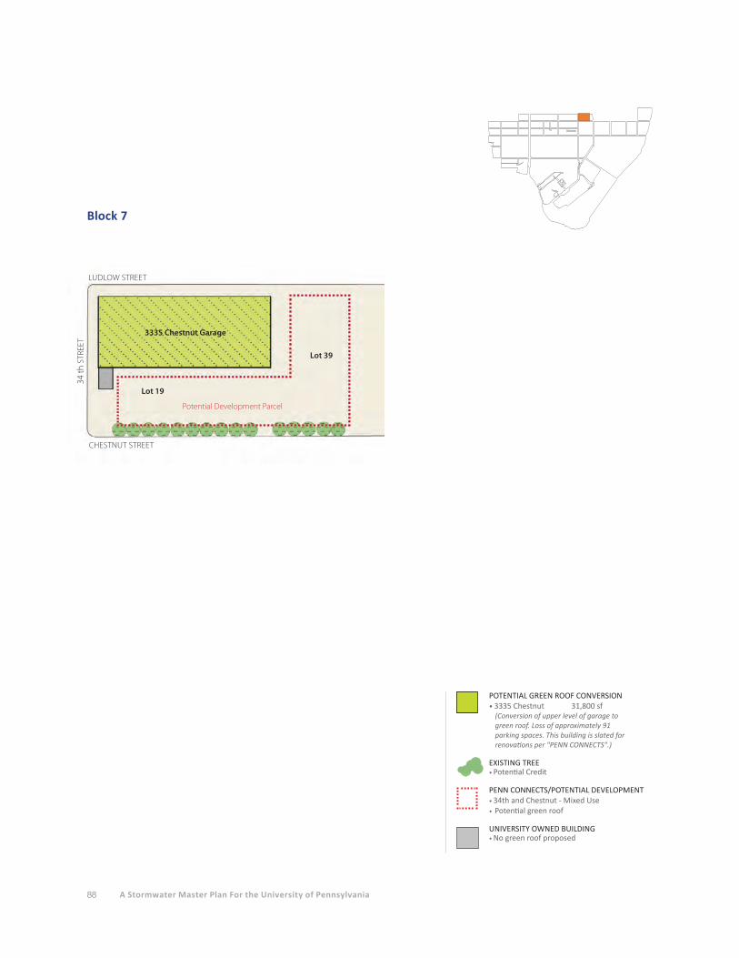
88 A Stormwater Master Plan For the University of Pennsylvania
Block 7
POTENTIAL GREEN ROOF CONVERSION • 3335 Chestnut 31,800 sf
(Conversion of upper level of garage to green roof. Loss of approximately 91 parking spaces. This building is slated for renovations per "PENN CONNECTS".)
EXISTING TREE • Potential Credit
PENN CONNECTS/POTENTIAL DEVELOPMENT• 34th and Chestnut - Mixed Use• Potential green roof
UNIVERSITY OWNED BUILDING• No green roof proposed
34 th
STR
EET
CHESTNUT STREET
LUDLOW STREET
3335 Chestnut Garage
Lot 19
Lot 39
Potential Development Parcel

89Section 5 FINDING SUSTAINABLE STORMWATER MANAGEMENT OPPORTUNITIES
Block 8
POTENTIAL GREEN ROOF CONVERSION • Kings Court 12,700 sf• Tanenbaum Hall 16,600 sf• Gittis Hall 11,500 sf• 133 S. 36th 6,420 sf• Franklin Annex 19,500 sf• 3401 Walnut 43,930 sf
EXISTING GREEN ROOF • Golkin Hall 7,210 sf• English House 11,520 sf
EXISTING POROUS PAVEMENT• Golkin Hall 7,420 sf
POTENTIAL BIORETENTION AREA• In existing grass area to manage roofs
EXISTING GREEN SPACE
EXISTING TREE • Potential Credit
EXISTING PAVEMENT • Potential Disconnection
PENN CONNECTS/POTENTIAL DEVELOPMENT• Potential green roof
UNIVERSITY OWNED BUILDING• No green roof proposed
• Buildings less feasible for green roof retrofitA
34 th
STR
EET
CHESTNUT STREET
Gittis Hall
Golkin Hall
Silverman HallEnglish House Tanenbaum Hall
Kings Court
36 th
STR
EET
WALNUT STREET
SANSOM STREET
Sansom Row
133 S. 36th
3401 Walnut Street
Moravian Street
A
A
A
A
GO
AT
Franklin Buiding Annex
Franklin BuidingFranklin Building Revevelopment
Proposed Mixed-use
Parcel

90 A Stormwater Master Plan For the University of Pennsylvania
Block 9
WALNUT STREET
Hill House
A
CHESTNUT STREET
McNeil Center
Zeta Psi
33 rd
STR
EET
34 th
STR
EET
POTENTIAL GREEN ROOF CONVERSION • Hill House 37,640 sf
(This building is slated for renovations per "PENN CONNECTS")
POROUS PAVEMENT CONVERSION 8,340 sf
POTENTIAL BIORETENTION AREA• In existing grass area to manage pavements
and/or roofs.
POTENTIAL SUBSURFACE INFILTRATION/DETENTION• For new building
EXISTING GREEN SPACE
EXISTING TREE CREDITS• PWD Approved - 8/2011 11,178 sf
PENN CONNECTS/POTENTIAL DEVELOPMENT• Potential green roof
UNIVERSITY OWNED BUILDING• No green roof proposed
• Buildings less feasible for green roof retrofitA
New College House
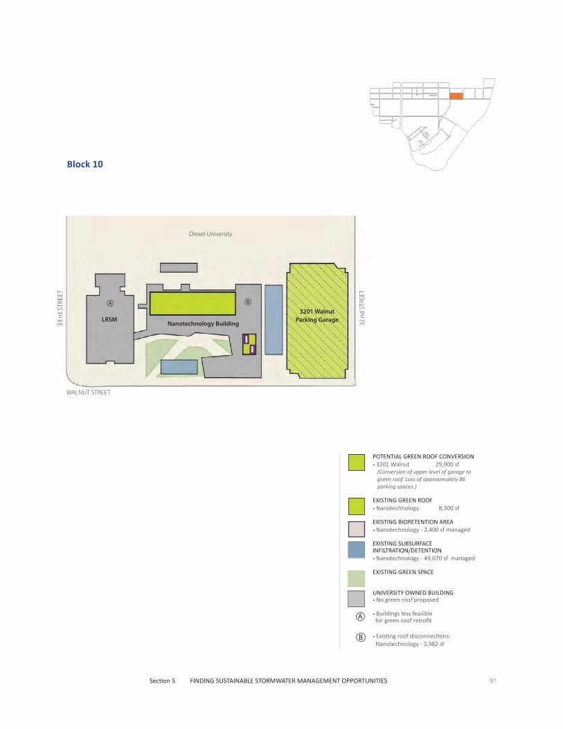
91Section 5 FINDING SUSTAINABLE STORMWATER MANAGEMENT OPPORTUNITIES
Block 10
POTENTIAL GREEN ROOF CONVERSION • 3201 Walnut 29,900 sf
(Conversion of upper level of garage to green roof. Loss of approximately 86 parking spaces.)
EXISTING GREEN ROOF • Nanotechnology 8,300 sf
EXISTING BIORETENTION AREA• Nanotechnology - 2,400 sf managed
EXISTING SUBSURFACE INFILTRATION/DETENTION• Nanotechnology - 49,070 sf managed
EXISTING GREEN SPACE
UNIVERSITY OWNED BUILDING• No green roof proposed
• Buildings less feasible for green roof retrofit
• Existing roof disconnections: Nanotechnology - 3,982 sf
B
A
3201 Walnut Parking Garage
Nanotechnology Building
WALNUT STREET
33 rd
STR
EET
A B
32 n
d ST
REET
LRSM
Drexel University
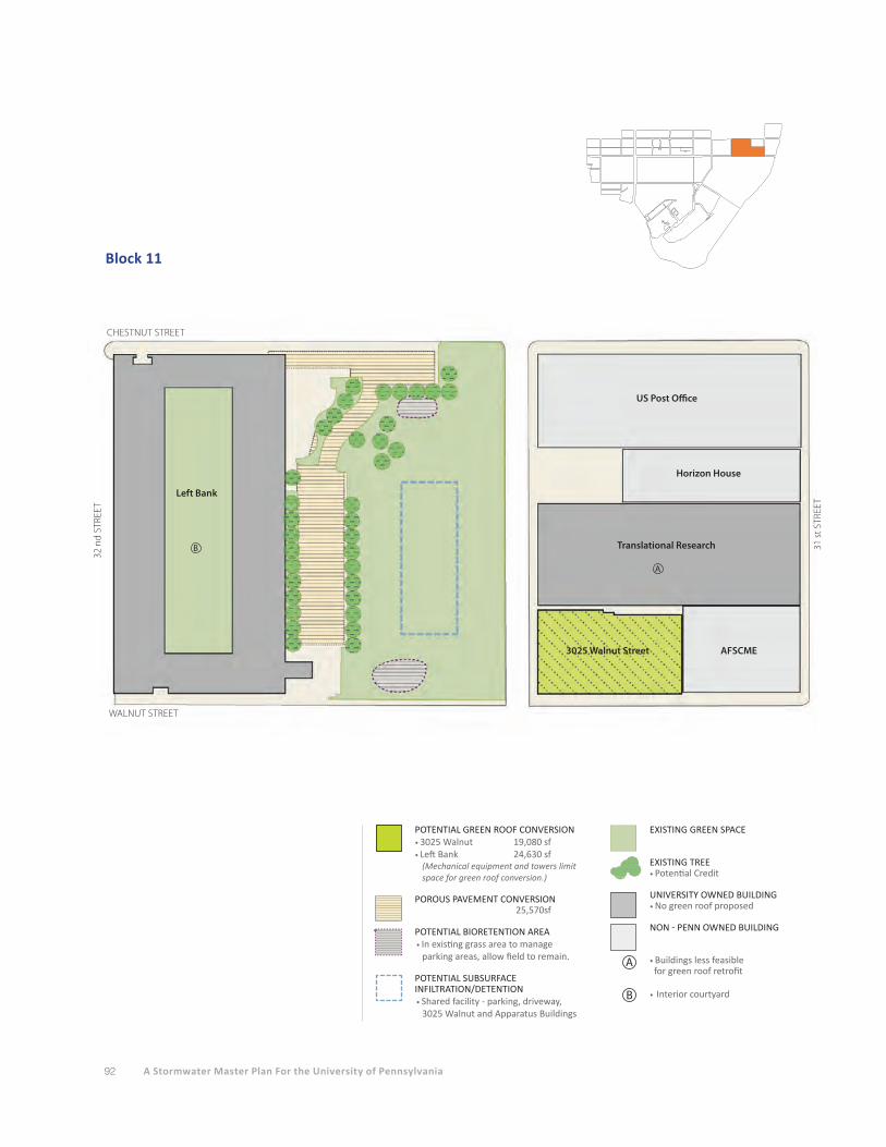
92 A Stormwater Master Plan For the University of Pennsylvania
Block 11
POTENTIAL GREEN ROOF CONVERSION • 3025 Walnut 19,080 sf• Left Bank 24,630 sf
(Mechanical equipment and towers limit space for green roof conversion.)
POROUS PAVEMENT CONVERSION 25,570sf
POTENTIAL BIORETENTION AREA• In existing grass area to manage parking areas, allow field to remain.
POTENTIAL SUBSURFACE INFILTRATION/DETENTION• Shared facility - parking, driveway,
3025 Walnut and Apparatus Buildings
EXISTING GREEN SPACE
EXISTING TREE • Potential Credit
UNIVERSITY OWNED BUILDING• No green roof proposed
NON - PENN OWNED BUILDING
• Buildings less feasible for green roof retrofit
• Interior courtyardB
A
3025 Walnut Street
Translational Research
Left Bank
B
A
WALNUT STREET
32 n
d ST
REET
31 s
t STR
EET
CHESTNUT STREET
US Post Office
Horizon House
AFSCME

93Section 5 FINDING SUSTAINABLE STORMWATER MANAGEMENT OPPORTUNITIES
Block 12
WALNUT STREET
30 th
STR
EET
CHESTNUT STREET
Cira Center South
Cira South Chestnut :Mixed-use residential with on grade retail
Cira South Walnut:Mixed-use office/residential/
retail
POTENTIAL GREEN ROOF CONVERSION • Cira Center South 53,850 sf
EXISTING SUBSURFACE INFILTRATION/DETENTION• Managed 53,850 sf
EXISTING GREEN SPACE
PENN CONNECTS/POTENTIAL DEVELOPMENT• Future Buildings• Potential green roof
NON - PENN OWNED BUILDING

94 A Stormwater Master Plan For the University of Pennsylvania
Block 13
SPRUCE STREET
The Rotunda Bridge Cinema and Shops
Evans Dental School
Levy Center
LOCUST STREET
WALNUT STREET
A
A
A
40 th
STR
EET
Shattner
B
B
B
POTENTIAL GREEN ROOF CONVERSION • Levy/Schattner 17,000 sf
POTENTIAL BIORETENTION AREA• To manage roof
POTENTIAL SUBSURFACE INFILTRATION/DETENTION• To manage roof
EXISTING TREE • Potential Credit
UNIVERSITY OWNED BUILDING• No green roof proposed
• Buildings less feasible for green roof retrofit
• Buildings slated for renovation per "PENN CONNECTS"
B
A
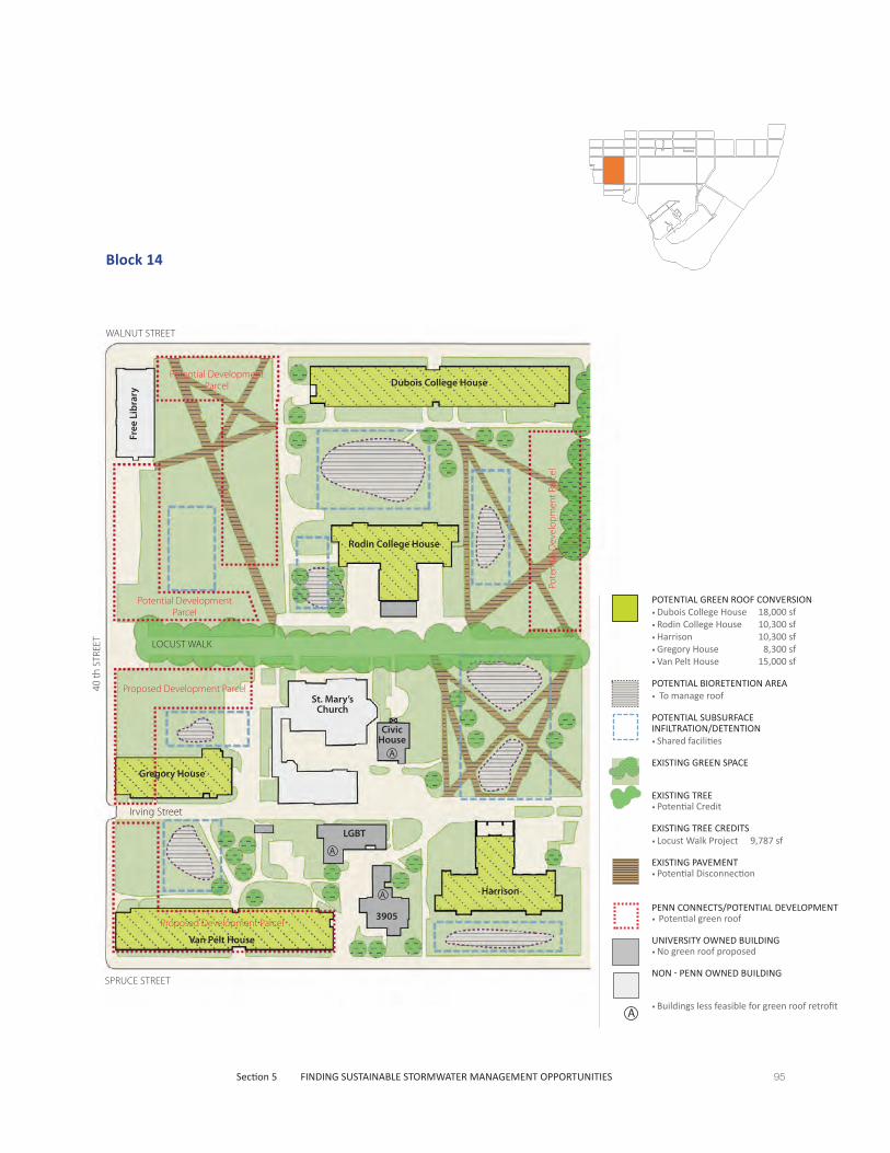
95Section 5 FINDING SUSTAINABLE STORMWATER MANAGEMENT OPPORTUNITIES
Block 14
SPRUCE STREET
40 th
STR
EET
WALNUT STREET
Dubois College House
Free
Lib
rary
Rodin College House
St. Mary’s Church
Civic House
Harrison
LGBT
3905
Van Pelt House
LOCUST WALK
Irving Street
Gregory House
A
A
A
POTENTIAL GREEN ROOF CONVERSION • Dubois College House 18,000 sf• Rodin College House 10,300 sf• Harrison 10,300 sf• Gregory House 8,300 sf• Van Pelt House 15,000 sf
POTENTIAL BIORETENTION AREA• To manage roof
POTENTIAL SUBSURFACE INFILTRATION/DETENTION• Shared facilities
EXISTING GREEN SPACE
EXISTING TREE • Potential Credit
EXISTING TREE CREDITS• Locust Walk Project 9,787 sf
EXISTING PAVEMENT • Potential Disconnection
PENN CONNECTS/POTENTIAL DEVELOPMENT• Potential green roof
UNIVERSITY OWNED BUILDING• No green roof proposed
NON - PENN OWNED BUILDING
• Buildings less feasible for green roof retrofitA
Proposed Development Parcel
Potential Development Parcel
Potential Development Parcel
Proposed Development Parcel
Pote
ntia
l Dev
elop
men
t Par
cel

96 A Stormwater Master Plan For the University of Pennsylvania
Block 15
A
SPRUCE STREET
WALNUT STREET
LOCUST WALK
38 th
STR
EET
Fels Center
President’s House
3808-10
Walnut
SteinhardtHillel
Alpha Tau Omega
SigmaChi
Kelly
Writ
er’s
Hou
se
Kappa Alpha
Class of 1920 Commons
ParkingGarage
Harnwell
Zeta Beta Tau
Mayer Hall
B
A
A
A
A
A
A
POTENTIAL GREEN ROOF CONVERSION • Fels Center 2,530 sf• Steinhardt Hall 7,940 sf• Harnwell 11,400sf • 1920 Commons 6,300 sf• Mayer Hall 8,500 sf• Parking Garage 30,000 sf
(Loss of approx. 90 parking spaces.)
POROUS PAVEMENT CONVERSION 16,450 sf
POTENTIAL BIORETENTION AREA• To manage pavement and/or roofs
POTENTIAL SUBSURFACE INFILTRATION/DETENTION• To manage pavement and/or roofs
EXISTING GREEN SPACE
EXISTING TREE • Potential Credit
EXISTING TREE CREDITS• Locust Walk Project 6,487 sf
EXISTING PAVEMENT • Potential Disconnection
PENN CONNECTS/POTENTIAL DEVELOPMENT• Potential green roof
UNIVERSITY OWNED BUILDING• No green roof proposed
• Buildings less feasible for green roof retrofit
• Buildings slated for renovation per "PENN CONNECTS"
B
A
Potential Development
Parcel
Proposed Addition
Future Building - Garage 14
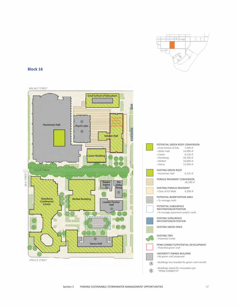
97Section 5 FINDING SUSTAINABLE STORMWATER MANAGEMENT OPPORTUNITIES
Block 16
POTENTIAL GREEN ROOF CONVERSION • Grad School of Edu 7,500 sf• Stitler Hall 14,000 sf• Caster 6,120 sf• Steinberg 34,700 sf• McNeil 19,000 sf• Vance 12,950 sf
EXISTING GREEN ROOF • Huntsman Hall 4,125 sf
POROUS PAVEMENT CONVERSION 18,190 sf
EXISTING POROUS PAVEMENT• Class of 62 Walk 4,200 sf
POTENTIAL BIORETENTION AREA• To manage roofs
POTENTIAL SUBSURFACE INFILTRATION/DETENTION• To manage pavement and/or roofs
EXISTING SUBSURFACE INFILTRATION/DETENTION
EXISTING GREEN SPACE
EXISTING TREE • Potential Credit
PENN CONNECTS/POTENTIAL DEVELOPMENT• Potential green roof
UNIVERSITY OWNED BUILDING• No green roof proposed
• Buildings less feasible for green roof retrofit
• Buildings slated for renovation per "PENN CONNECTS"B
A
Huntsman Hall Psych Labs
Grad School of Education
Caster Building
McNeil Building
Vance Hall
Steinberg Conference
CenterLauder Fischer
Hall
Kappa Sigma
Phi Delta Theta
Stiteler Hall
A
B
B
WALNUT STREET
SPRUCE STREET
LOCUST WALK
38 th
STR
EET
A
A
A
Proposed Building:Replaces
Stiteler Hall

98 A Stormwater Master Plan For the University of Pennsylvania
Block 17
Annenberg Center
WALNUT STREET
SPRUCE STREET
CLA
SS O
F 62
’ WA
LK
LOCUST WALK
Annenberg SchoolAdams Hall
APPC
Locu
st
Hou
se
Colo
nial
Pen
n Ce
nter
Del
ta P
si
Del
ta P
hi
Phi G
amm
a D
elta
Phi S
igm
a Ka
ppa
The Arch36093611
Steinberg / Dietrich Hall
The Castle
Wistar Institute
A
A
A
POTENTIAL GREEN ROOF CONVERSION • Annenberg Center 27,300 sf• Annenberg School 18,750 sf
(Partial conversion -multiple levels)• Adams Hall 7,250 sf
(Partial conversion)• APPC 6,050 sf• Locust House 2,300 sf• Delta Psi 3,350 sf• Delta Phi 2,600 sf• Phi Signa Kappa 3,800 sf• 3609/3611 2,950 sf• The Arch 3,700 sf
(Partial conversion)• Steinberg/Dietrich 55,250 sf
POROUS PAVEMENT CONVERSION 26,000 sf
EXISTING POROUS PAVEMENT
POTENTIAL SUBSURFACE INFILTRATION/DETENTION• To manage pavement and/or roofs.
EXISTING SUBSURFACE INFILTRATION/DETENTION• Manages 7,094 sf
EXISTING GREEN SPACE
EXISTING TREE • Potential Credit
EXISTING TREE CREDITS• Locust Walk Project 12,749 sf
PENN CONNECTS/POTENTIAL DEVELOPMENT• Potential green roof
UNIVERSITY OWNED BUILDING• No green roof proposed
NON - PENN OWNED BUILDING
• Buildings less feasible for green roof retrofitA
Prop
osed
W
est A
dditi
on
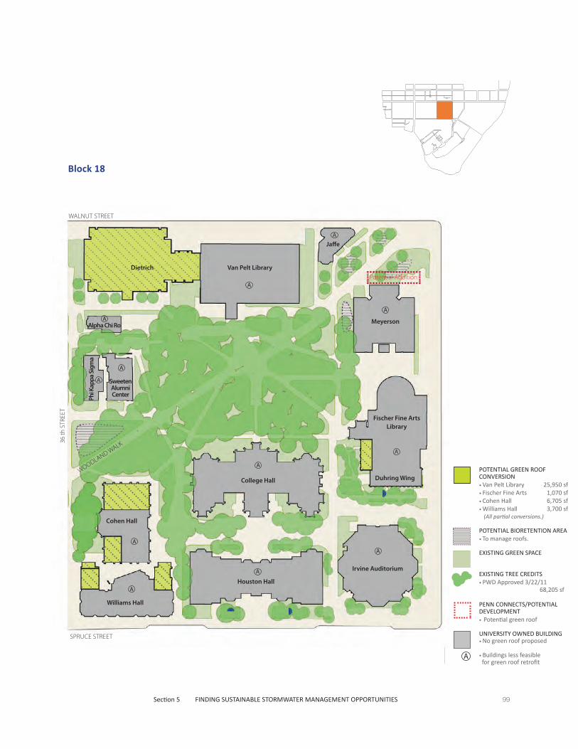
99Section 5 FINDING SUSTAINABLE STORMWATER MANAGEMENT OPPORTUNITIES
Block 18
POTENTIAL GREEN ROOF CONVERSION • Van Pelt Library 25,950 sf• Fischer Fine Arts 1,070 sf• Cohen Hall 6,705 sf• Williams Hall 3,700 sf
(All partial conversions.)
POTENTIAL BIORETENTION AREA• To manage roofs.
EXISTING GREEN SPACE
EXISTING TREE CREDITS• PWD Approved 3/22/11 68,205 sf
PENN CONNECTS/POTENTIAL DEVELOPMENT• Potential green roof
UNIVERSITY OWNED BUILDING• No green roof proposed
• Buildings less feasible for green roof retrofit
A
Van Pelt Library
WALNUT STREET
SPRUCE STREET
WOODLAND WALK36 th
STR
EET
Jaffe
Alpha Chi Ro Meyerson
Fischer Fine Arts Library
Duhring WingCollege Hall
Phi K
appa
Sig
ma
Sweeten Alumni Center
Cohen Hall
Williams Hall
Houston Hall
Irvine AuditoriumA
A
A
A
A
A
A
A
A
A
A
A
DietrichPotential Addition
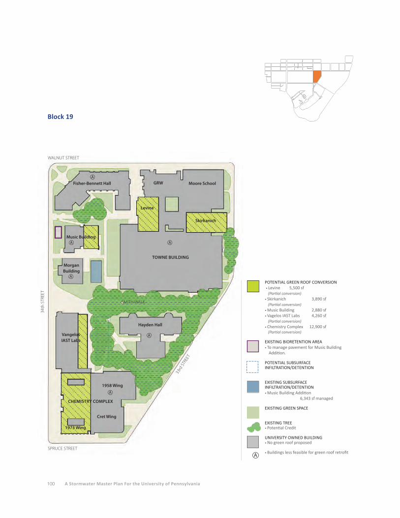
100 A Stormwater Master Plan For the University of Pennsylvania
Block 19
Fisher-Bennett Hall
WALNUT STREET
SPRUCE STREET
34th
STR
EET
SMITH WALK
GRW Moore School
Levine
Skirkanich
TOWNE BUILDING
Music Building
MorganBuilding
Hayden Hall
1958 Wing
CHEMISTRY COMPLEX
Cret Wing
1973 Wing
VangelosIAST Labs
33rd
STR
EET
A
A
A
A
A
A
POTENTIAL GREEN ROOF CONVERSION • Levine 5,500 sf
(Partial conversion)• Skirkanich 3,890 sf
(Partial conversion)• Music Building 2,880 sf• Vagelos IAST Labs 4,260 sf
(Partial conversion)• Chemistry Complex 12,900 sf
(Partial conversion)
EXISTING BIORETENTION AREA• To manage pavement for Music Building
Addition.
POTENTIAL SUBSURFACE INFILTRATION/DETENTION
EXISTING SUBSURFACE INFILTRATION/DETENTION• Music Building Addition
6,343 sf managed
EXISTING GREEN SPACE
EXISTING TREE • Potential Credit
UNIVERSITY OWNED BUILDING• No green roof proposed
• Buildings less feasible for green roof retrofitA
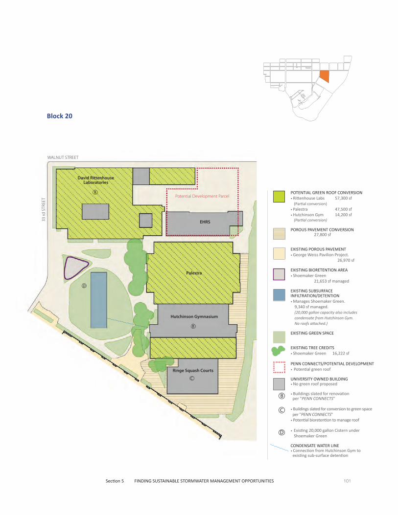
101Section 5 FINDING SUSTAINABLE STORMWATER MANAGEMENT OPPORTUNITIES
Block 20
POTENTIAL GREEN ROOF CONVERSION • Rittenhouse Labs 57,300 sf
(Partial conversion)• Palestra 47,500 sf• Hutchinson Gym 14,200 sf
(Partial conversion)
POROUS PAVEMENT CONVERSION 27,800 sf
EXISTING POROUS PAVEMENT• George Weiss Pavilion Project. 26,970 sf
EXISTING BIORETENTION AREA• Shoemaker Green 21,653 sf managed
EXISTING SUBSURFACE INFILTRATION/DETENTION• Manages Shoemaker Green.
9,340 sf managed. (20,000 gallon capacity also includes condensate from Hutchinson Gym. No roofs attached.)
EXISTING GREEN SPACE
EXISTING TREE CREDITS• Shoemaker Green 16,222 sf
PENN CONNECTS/POTENTIAL DEVELOPMENT
• Potential green roof
UNIVERSITY OWNED BUILDING• No green roof proposed
• Buildings slated for renovation per "PENN CONNECTS"
• Buildings slated for conversion to green space per "PENN CONNECTS"
• Potential bioretention to manage roof
• Existing 20,000 gallon Cistern under Shoemaker Green
CONDENSATE WATER LINE• Connection from Hutchinson Gym to existing sub-surface detention
B
C
D
D
WALNUT STREET
33 rd
STR
EET
David Rittenhouse Laboratories
Palestra
Hutchinson Gymnasium
Ringe Squash Courts
EHRS
B
B
C
Potential Development Parcel

102 A Stormwater Master Plan For the University of Pennsylvania
Block 21
WALNUT STREET
Class of 1923 Ice Rink
Levy Tennis Pavilion
A
POTENTIAL GREEN ROOF CONVERSION • 1923 Ice Rink 46,000 sf
POROUS PAVEMENT CONVERSION 57,800 sf
POTENTIAL SUBSURFACE INFILTRATION/DETENTION• 1923 Ice Rink 46,000 sf
EXISTING GREEN SPACE
UNIVERSITY OWNED BUILDING• No green roof proposed
• Buildings less feasible for green roof retrofitA

103Section 5 FINDING SUSTAINABLE STORMWATER MANAGEMENT OPPORTUNITIES
Block 22
WALNUT STREET
Impervious Tennis Courts
Parking
EXISTING BIORETENTION AREA• Penn Park 115,366 sf managed
EXISTING SUBSURFACE INFILTRATION/DETENTION• Penn Park 346,366 sf managed
EXISTING GREEN SPACE
EXISTING PAVEMENT• Penn Park 26,530 sf managed
UNIVERSITY OWNED BUILDING• No green roof proposed
Dunning Cohen Field(synthetic turf)
Addams Field(synthetic turf)
Multi-purpose Field
Parking
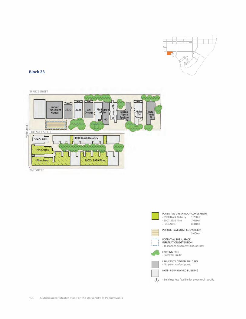
104 A Stormwater Master Plan For the University of Pennsylvania
Block 23
SPRUCE STREET
PINE STREET
3930 3928 Chi Omega
Phi Kappa Alpha
Pi L
amda
Phi
Sigma Alpha
Epsilon
Alpha Chi
Omega
BetaTheda
Pi
40 th
STR
EET
DELANCY STREET
3900 Block Delancy
3907 - 3939 Pine
364 S. 40th
Pine Arms
Pine Arms
A
Barker Transplant
House
POTENTIAL GREEN ROOF CONVERSION • 3900 Block Delancy 1,200 sf• 3907-3939 Pine 7,660 sf• Pine Arms 8,340 sf
POROUS PAVEMENT CONVERSION 3,000 sf
POTENTIAL SUBSURFACE INFILTRATION/DETENTION• To manage pavements and/or roofs
EXISTING TREE • Potential Credit
UNIVERSITY OWNED BUILDING• No green roof proposed
NON - PENN OWNED BUILDING
• Buildings less feasible for green roof retrofitA
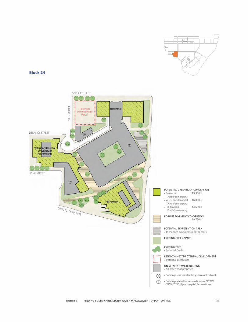
105Section 5 FINDING SUSTAINABLE STORMWATER MANAGEMENT OPPORTUNITIES
Block 24
SPRUCE STREET
UNIVERSITY AVENUE
DELANCY STREET
Rosenthal
Hill Pavilion
Veterinary HospitalUniversity of Pennsylvania
A
A
B
PINE STREET
39 th
STR
EET
Potential Development
Parcel
POTENTIAL GREEN ROOF CONVERSION • Rosenthal 13,300 sf (Partial conversion)• Veterinary Hospital 16,800 sf (Partial conversion)• Hill Pavilion 14,600 sf (Partial conversion)
POROUS PAVEMENT CONVERSION 19,750 sf
POTENTIAL BIORETENTION AREA• To manage pavements and/or roofs
EXISTING GREEN SPACE
EXISTING TREE • Potential Credit
PENN CONNECTS/POTENTIAL DEVELOPMENT• Potential green roof
UNIVERSITY OWNED BUILDING• No green roof proposed
• Buildings less feasible for green roof retrofit
• Buildings slated for renovation per "PENN CONNECTS", Ryan Hospital Renovations.
B
A
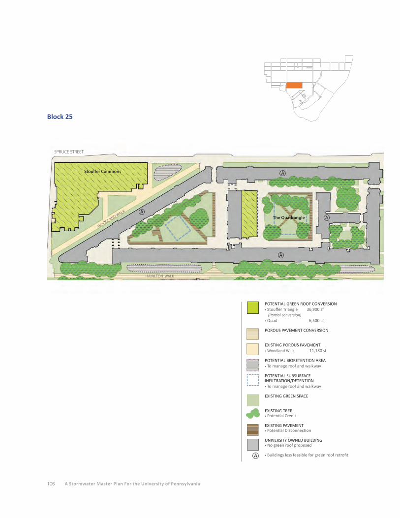
106 A Stormwater Master Plan For the University of Pennsylvania
Block 25
Stouffer Commons
SPRUCE STREET
WOODLAND WALK
The QuadrangleA
A
A
A
HAMILTON WALK
POTENTIAL GREEN ROOF CONVERSION • Stouffer Triangle 36,900 sf
(Partial conversion)• Quad 6,500 sf
POROUS PAVEMENT CONVERSION
EXISTING POROUS PAVEMENT• Woodland Walk 11,180 sf
POTENTIAL BIORETENTION AREA• To manage roof and walkway
POTENTIAL SUBSURFACE INFILTRATION/DETENTION• To manage roof and walkway
EXISTING GREEN SPACE
EXISTING TREE • Potential Credit
EXISTING PAVEMENT • Potential Disconnection
UNIVERSITY OWNED BUILDING• No green roof proposed
• Buildings less feasible for green roof retrofitA

107Section 5 FINDING SUSTAINABLE STORMWATER MANAGEMENT OPPORTUNITIES
Block 26
Hospital of the University of Pennsylvania
34 th
STR
EET
SPRUCE STREET
A
Spruce Street Plaza
EXISTING POROUS PAVEMENT 3,950 sf
POROUS PAVEMENT CONVERSION
EXISTING GREEN SPACE
EXISTING TREE • Potential Credit
UNIVERSITY OWNED BUILDING• No green roof proposed
• Buildings less feasible for green roof retrofitA
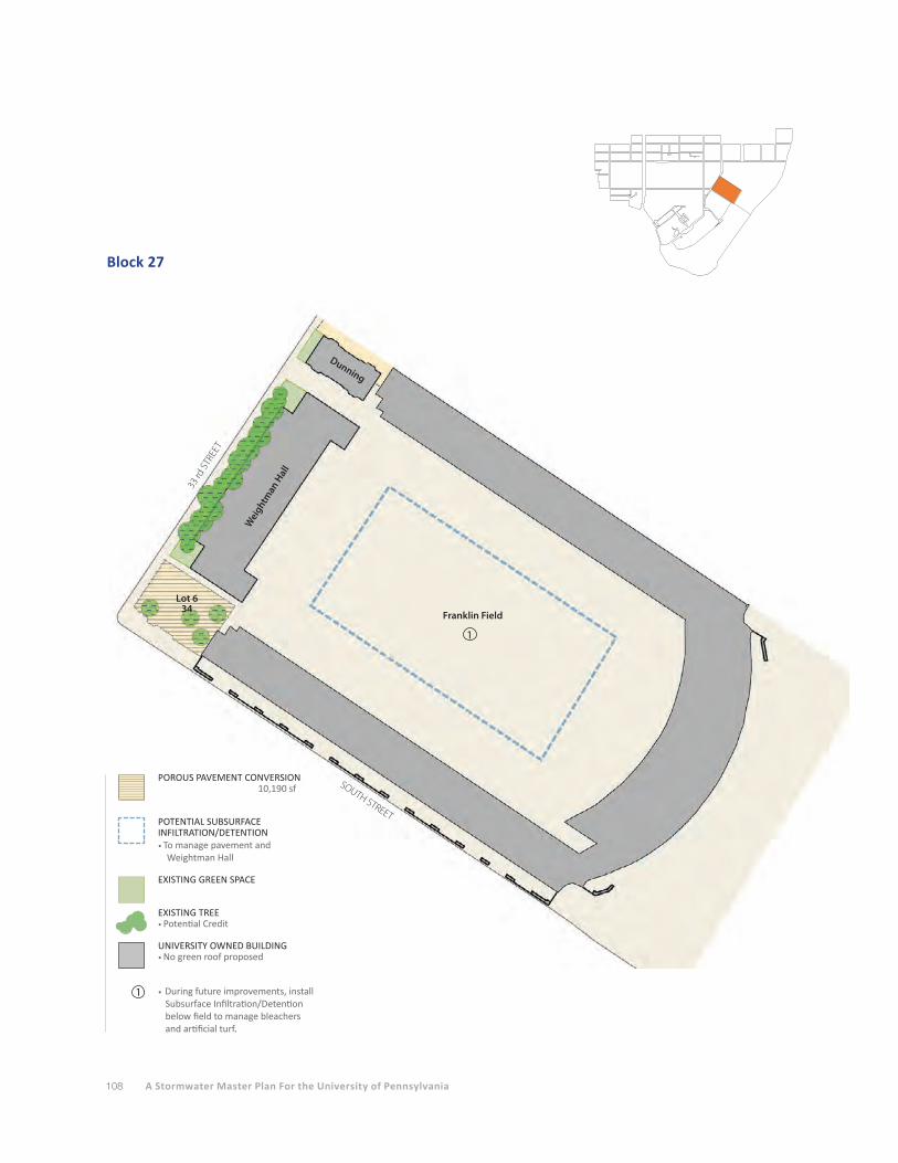
108 A Stormwater Master Plan For the University of Pennsylvania
Block 27
Franklin Field
Wei
ghtman
Hal
l
Lot 634
Dunning
33 rd
STR
EET
SOUTH STREET
1
1
POROUS PAVEMENT CONVERSION 10,190 sf
POTENTIAL SUBSURFACE INFILTRATION/DETENTION• To manage pavement and Weightman Hall
EXISTING GREEN SPACE
EXISTING TREE • Potential Credit
UNIVERSITY OWNED BUILDING• No green roof proposed
• During future improvements, install Subsurface Infiltration/Detention below field to manage bleachers and artificial turf.
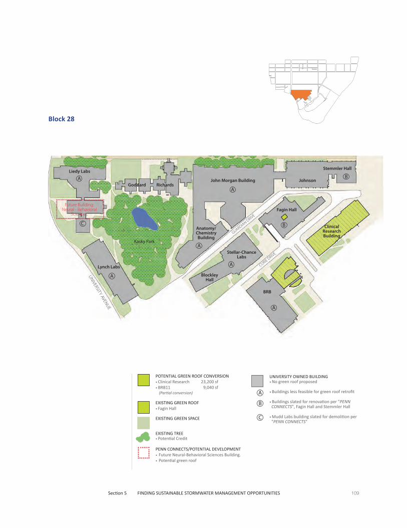
109Section 5 FINDING SUSTAINABLE STORMWATER MANAGEMENT OPPORTUNITIES
Block 28
John Morgan Building
GUARDIAN DRIVE
Johnson
Stemmler HallLiedy Labs
Lynch Labs
Anatomy/Chemistry Building
Blockley Hall
Stellar-Chance Labs
Fagin Hall
Clinical Research Building
Kasky Park
Goddard Richards
UNIVERSITY AVENUE
CURIE DRIVE
BRB
B
A
A
A
A
A
A
BC
UNIVERSITY OWNED BUILDING• No green roof proposed
• Buildings less feasible for green roof retrofit
• Buildings slated for renovation per "PENN CONNECTS", Fagin Hall and Stemmler Hall
• Mudd Labs building slated for demolition per "PENN CONNECTS"
B
A
C
POTENTIAL GREEN ROOF CONVERSION • Clinical Research 23,200 sf• BRB11 9,040 sf
(Partial conversion)
EXISTING GREEN ROOF • Fagin Hall
EXISTING GREEN SPACE
EXISTING TREE • Potential Credit
PENN CONNECTS/POTENTIAL DEVELOPMENT• Future Neural-Behavioral Sciences Building.• Potential green roof
Future Building:Neural - Behavioral
Sciences.
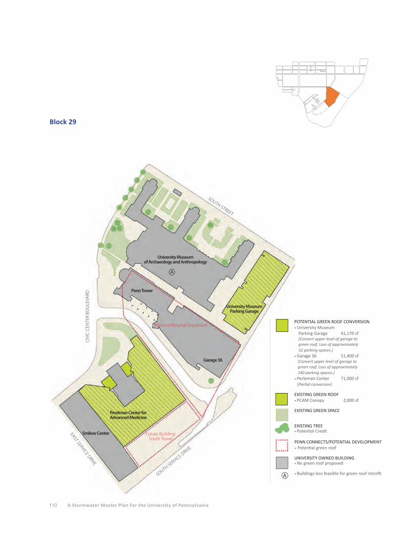
110 A Stormwater Master Plan For the University of Pennsylvania
Block 29
EAST SERVICE DRIVE
University Museum of Archaeology and Anthropology
University Museum Parking Garage
Garage 36
Perelman Center for Advanced Medicine
Penn Tower
CIV
IC C
ENTE
R BO
ULE
VARD
SOUTH SERVICE DRIVE
A
SOUTH STREET
Smilow Center
POTENTIAL GREEN ROOF CONVERSION• University Museum
Parking Garage 41,170 sf(Convert upper level of garage togreen roof. Loss of approximately 52 parking spaces.)
• Garage 36 51,400 sf(Convert upper level of garage to green roof. Loss of approximately 140 parking spaces.)
• Perleman Center 71,000 sf (Partial conversion)
EXISTING GREEN ROOF • PCAM Canopy 2,000 sf EXISTING GREEN SPACE
EXISTING TREE • Potential Credit
PENN CONNECTS/POTENTIAL DEVELOPMENT• Potential green roof
UNIVERSITY OWNED BUILDING• No green roof proposed
• Buildings less feasible for green roof retrofitA
Future Building:South Tower
Planned Hospital Expansion

111Section 5 FINDING SUSTAINABLE STORMWATER MANAGEMENT OPPORTUNITIES
Block 30
CIVIC CENTER BOULEVARD
Garage
HEALTH SCIENCES DRIVE
SOU
TH U
NIVERSTIY AVEN
UE
WEST SERVICE DRIVE
POTENTIAL GREEN ROOF CONVERSION• Garage 68,300 sf
(Convert upper level of garage to green roof. Loss of approximately 188 parking spaces.)
EXISTING GREEN SPACE
PENN CONNECTS/POTENTIAL DEVELOPMENT• Future Building - PA Hall Site Redevelopment• Potential green roof
1000 Car Parking Garage:Phased Mixed-use Development

112 A Stormwater Master Plan For the University of Pennsylvania
Block 31
Mod 7 Chiller
1
UNIVERSITY AVENUE
Potential Development:
Chiller Expansion
1
POTENTIAL BIORETENTION AREA• To manage pavement and roofs.
EXISTING GREEN SPACE
EXISTING TREE CREDITS• PWD Approved Credit
14,630 sf
EXISTING PAVEMENT• PWD Approved Disconnection
Credit 8,800 sf
PENN CONNECTS/POTENTIAL DEVELOPMENT• Potential green roof
UNIVERSITY OWNED BUILDING• No green roof proposed
• Mod 7 Chiller. Existing credit for cooling tower water re-use 15,900 sf
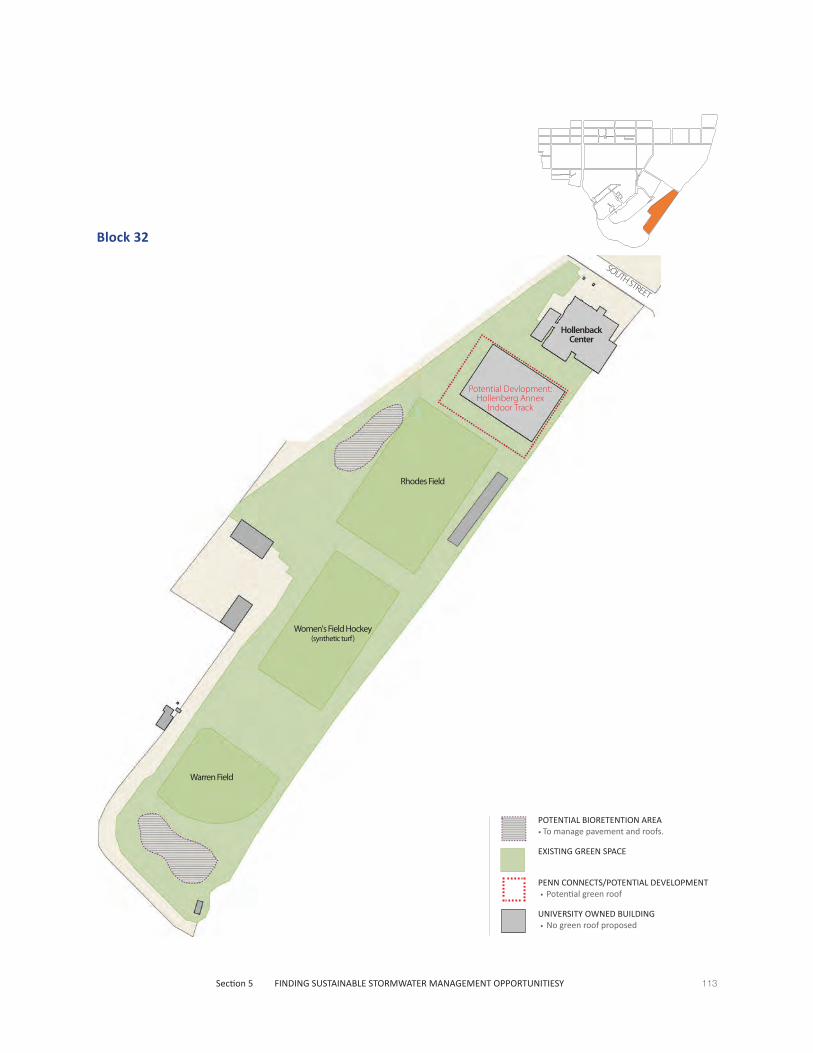
113
SOUTH STREET
Hollenback Center
Rhodes Field
Women's Field Hockey(synthetic turf)
Warren Field
Potential Devlopment:Hollenberg Annex
Indoor Track
Section 5 FINDING SUSTAINABLE STORMWATER MANAGEMENT OPPORTUNITIESY
Block 32
POTENTIAL BIORETENTION AREA• To manage pavement and roofs.
EXISTING GREEN SPACE
PENN CONNECTS/POTENTIAL DEVELOPMENT • Potential green roof
UNIVERSITY OWNED BUILDING • No green roof proposed

114 A Stormwater Master Plan For the University of Pennsylvania

Section 1 EXECUTIVE SUMMARY 115
Section 1 EXECUTIVE SUMMARY
Section 2 STORMWATER RUN-OFF FROM TODAY’S CAMPUS
Section 3 STORMWATER MANAGEMENT ON TODAY’S CAMPUS
Section 4 POTENTIAL STORMWATER MANAGEMENT PRACTICES FOR FUTURE PROJECTS
Section 5 FINDING SUSTAINABLE STORMWATER MANAGEMENT OPPORTUNITIES
Section 6 STORMWATER MANAGEMENT COSTS AND PWD FEES
Section 7 OPERATIONS AND MAINTENANCE CONSIDERATIONS
Section 8 LEGISLATION ISSUES AND FUNDING OPPORTUNITIES
Section 9 RECOMMENDATIONS
Section 10 APPENDICES
A. Representative Stormwater Management Details
B. Stormwater Management Model
C. References
D. Acknowledgements
116 A Stormwater Master Plan For the University of Pennsylvania
STORMWATER MANAGEMENT COSTS AND PWD FEES
This section provides information on typical construction costs for the various sustainable stormwater
management practices. The approximate cost ranges (in 2012 dollars) for each type of practice were
developed from Duffield Associate’s project experience; discussions with engineers, architects,
landscape architects, contractors, and manufacturer’s representatives; and various online resources.
The stormwater management construction costs are provided on a per square foot basis. This allows
for relative cost comparisons for different practices shown for the areas on the block-by-block graphics.
It should be noted that this does not necessarily provide an accurate comparison with respect to the
stormwater volume (cubic feet) that a given practice can manage per square foot of area. For example,
an extensive green roof and porous pavement may each be designed to manage one inch of runoff per
square foot of area, so these two practices are comparable on a cost per square foot basis. However, a
bioretention area may be several feet in depth, so that it can store significantly more water per square
foot of system than the green roof or porous pavement systems.
Ultimately, the PWD stormwater regulations will dictate what level of stormwater management is
required for a given project (e.g., water quality only vs. full flood control), the site design will determine
what practices may provide the required regulatory compliance (e.g., green roof on a proposed building
and/or porous pavement for a proposed parking area), and then site constraints will largely determine
which of those practices will work on the site (e.g., soil characteristics limiting infiltration may preclude
the use of porous pavement).
Materials and delivery costs for stormwater management practices can also fluctuate, (typically
upward) depending on multiple factors such as the price of oil. Some practices rely on plastic
components, others on bituminous (asphalt) components, and all require delivery from the
manufacturer’s source to the installation site on campus.
Following the summary of typical construction costs, the PWD stormwater fee structure is described.
Retrofitting existing construction to comply with the current regulations may result in a reduction
in the stormwater fee for a given parcel, and therefore may provide a return on the investment in
the retrofitting construction costs. However, as will be shown by examples, an adequate return on
investment period may be many years due to the fee structure.
Stormwater Management Practice Construction CostsA range of construction costs are provided for each stormwater management practice. For each
practice, there may be associated benefits that reduce other construction costs or that provide other
monetary benefits to the University. The value of these benefits are difficult to quantify due to the
infinite variety in potential site layout designs and the mix of stormwater management practices that
might be employed on a single site.

117Section 6 STORMWATER MANAGEMENT COSTS AND PWD FEES
Green RoofsGreen roofs are typically more expensive than conventional roofs not only because of the required
growing medium and plantings, but because the building’s roof structure may require more structural
strength to support the load of the green roof materials and the captured rainfall. The typical costs
below represent just the roof membrane and the green roof drainage components, growing medium,
and plantings.
• Extensive green roof (typical 3-inch thick growing medium): $8-15/sf
• Intensive green roof (typical 1-foot thick (or greater) growing medium): $25-30/sf
• Tray-system green roof (typical 3-inch thick growing medium): $17-20/sf.
• Conventional roof for comparison (new membrane only): $7-10/sf
The following factors may reduce the life cycle cost of a green roof system:
• Longer roof life due to protection of the roof membrane from ultraviolet rays,
• Reduced heating and cooling costs due to growing medium acting as insulation,
• A green roof may allow a site to meet the 20% reduction in existing impervious area and exempt
the site from the Flood Control requirement, thereby reducing stormwater management costs
for large detention facilities and the associated larger piping needed to convey runoff to the
systems,
• A green roof qualifies for a reduction in PWD stormwater fees.
Porous PavementPorous asphalt and concrete are typically more expensive than conventional pavements. However, the
use of porous pavement eliminates the storm inlets, piping, and subsurface stormwater management
systems required for standard asphalt paved areas, so in certain situations the use of porous pavement
may be a more economical choice. While the materials used in porous and conventional pavements
are similar, increased pavement costs are associated with the more expensive stone subbase materials
required for stormwater storage and the premium that may be paid for an asphalt plant to produce
a small volume of a specialty blend of materials. Depending on the intended level of stormwater
management in the pavement’s stone subbase, the depth of stone will vary and affect the cost per
square foot.
Mayfield Site Contractors, Inc., the firm involved in the Shoemaker Green project, provided the
approximate cost information below. The costs represent the installed cost with site preparation,
geotextile, subbase stone, choker course, and pavement. Mayfield indicated that these prices are
relevant for Penn’s campus-scale projects. As with most construction, the greater the quantity of
material used, the lower the unit cost.
• Porous asphalt (4" asphalt over 8" stone): $16/sf
• Conventional asphalt for comparison: $8/sf
• Porous concrete walkway (4" concrete over 4" stone): $15/sf
• Conventional concrete for comparison: $14/sf

118 A Stormwater Master Plan For the University of Pennsylvania
While the cost of porous asphalt is approximately twice that of standard asphalt, the use of porous
asphalt often eliminates the need for large underground detention systems and the inlets and piping
needed to convey runoff to the systems.
Note that the cost of porous concrete in a typical sidewalk installation is only slightly more than
standard concrete, so porous concrete might be the preferred choice if the underlying soil infiltration
characteristics are acceptable. The cost of the paver system, such as those used on Woodland Walk
and Class of ’62 Walkway, are slightly higher than the porous and conventional concrete systems. A
concern with large quantities of porous concrete is getting a uniform color for all batches used within
one project.
The following factors may impact the life cycle cost of porous pavement:
• The use of porous pavement may allow a site to meet the 20% reduction in existing impervious
area and exempt the site from the Flood Control requirement, thereby reducing stormwater
management costs for large subsurface detention facilities and the associated inlets and larger
piping needed to convey runoff to the systems.
• The greater the material amount used, the lower the material and installation costs will be.
• Some research has shown that porous pavement requires less deicers to melt snow and ice.
• Porous pavement qualifies for a reduction in PWD stormwater fees.
• Higher maintenance costs to clean porous pavement may increase its lifecycle cost.
Bioretention Areas / Rain GardensBioretention areas and rain gardens provide the double function of stormwater management while
enhancing the aesthetic quality of a landscape. The costs for bioretention areas can fluctuate widely.
A relatively inexpensive system may be designed as an infiltrating area with several feet of amended
planting soil. If infiltration is not possible, an underdrain system may be required. A bioretention area
can also be located above a subsurface infiltration/detention system to provide additional stormwater
runoff storage for larger rain events. Overflow/outlet structures are typically included in the design to
allow runoff from large storms to bypass the system. The quantity and quality of the plantings will also
affect the construction cost.
• Bioretention area: $10-40/sf
These factors may reduce the effective cost of a bioretention area:
• While there may be increased long-term maintenance requirements in terms of weeding and
trimming, these costs are offset by reduced mowing requirements and, once established,
reduced irrigation, fertilizer, herbicide, and pesticide requirements.
• A bioretention area that manages runoff from impervious area qualifies for a reduction in PWD
stormwater fees for the managed impervious area.
• While not providing a direct cost savings to the University, bioretention areas provide the
intangible benefits of attractive and educational landscaping and improved wildlife habitat over
conventional turf or ground covers.
Subsurface Stormwater Management FacilitiesIt is difficult to provide a typical cost for subsurface infiltration/detention facilities. The systems may

119Section 6 STORMWATER MANAGEMENT COSTS AND PWD FEES
be constructed from a wide variety of materials (pipes of varying materials in a stone bed, concrete
vaults, manufactured plastic storage units). The horizontal and vertical dimensions of the systems will
vary widely depending on regulatory compliance requirements and site constraints limiting the extent
of the systems. While the construction cost of a subsurface system will likely be greater than that of
a comparable surface basin, the subsurface system preserves limited campus space for other uses;
for example, a system located beneath a parking area allows for both vehicle storage and stormwater
management on the same piece of ground.
By managing impervious area runoff in accordance with PWD’s regulations, subsurface systems can
reduce the PWD stormwater fees for the project site’s parcel.
Capture and Reuse SystemsLike subsurface systems, it is difficult to quantify the cost of a system that captures and reuses
rainwater for use inside a building because the system design will vary widely depending on the
intended use of the captured water and the complexity of the water treatment and plumbing system
within the building.
Capture/reuse, or rainwater harvesting, requires a significant investment in building infrastructure that
is not needed if public potable water is used for all building uses. Depending on the intended use of
the rainwater, a water treatment system may be required. A cistern, typically located in the basement
of the building or outside of the building footprint, is required. A second parallel plumbing system is
required to provide public water to the plumbing fixtures during dry periods when the cistern is empty.
From a sustainability education perspective, these systems send a strong message about natural
resource conservation, but the relatively inexpensive cost of potable water typically results in a lengthy
period for adequate return on investment for the construction costs.
If the captured rainwater is used year-round within a building in accordance with PWD’s requirements
(ie, system is capable of capturing one inch of runoff from the building roof and is used within 72 hours
following the rain event), then the contributing roof area is considered managed and is eligible for a
PWD stormwater fee reduction.
A capture/reuse system used to provide water just for landscape irrigation will save costs for potable
water but, as discussed in Section 4, will not qualify for a PWD fee reduction.
PWD Stormwater Fees and CreditsIn 2009, PWD began a five-year phase-in of a parcel-based stormwater fee system for all
non-residential properties in the City. The fees will be fully implemented on July 1, 2013. The monthly
fee consists of two parts: a Gross Area (GA) charge and an Impervious Area (IA) charge.
The GA charge is based on the gross area of the parcel and assumes that all lots are 70 percent
impervious area. The fee is $0.53 per 500 square feet of gross parcel area. If a parcel has less than 70
percent impervious area, the property owner can apply to PWD for a credit that will reduce the fee to

120 A Stormwater Master Plan For the University of Pennsylvania
reflect the actual impervious area. The entire GA fee can be eliminated if a property’s impervious area
is less than 30 percent.
The IA charge is based on the impervious area located on a parcel. The fee is $4.17 per 500 square feet
of impervious area. The fee can be reduced to the extent that the impervious areas are managed in
accordance with PWD’s regulations.
Projects with stormwater management practices constructed both before and since PWD instituted the
stormwater regulations in 2006 must apply to PWD to receive credit for the facilities. The applications
require the signature and seal of a licensed professional (engineer, architect, or landscape architect)
and have an application fee of $150.00. The credits must be renewed every four years for a $50.00 fee.
Return on Investment Period for Stormwater Management Construction CostsA reduction of the PWD stormwater fee provides an incentive to retrofit an existing parcel or building
with a stormwater management practice that meets the PWD regulations. However, at this time, the
fee structure may result in a lengthy return-on-investment period.
As an example, assume that a building with a 10,000 square foot roof is considered for retrofitting with
a green roof and that the existing structure does not need any additional reinforcing to support the
green roof (for reference, the green roof area on the Nanotechnology building is 8,300 square feet).
At a typical cost of $12 per square foot for an extensive green roof (3-inch growing medium meeting
PWD’s minimum requirements), the approximate retrofit construction cost would be $120,000. The
addition of the green roof would exempt the building from the Impervious Area charge. At the IA
charge rate of $4.17 per 500 square feet per month, the monthly IA charge for 10,000 square feet of
impervious area is $83.40, or an annual charge of $1,000.80. Therefore, the return-on-investment
period for the green roof installation cost would be approximately 120 years, which certainly exceeds
the life cycle of the roof and possibly the building.
Depending on the overall percentage of impervious area on the parcel, the addition of the green roof
may also reduce the Gross Area charge (ie, by reducing the total impervious area below the assumed
70 percent impervious area), but because the GA charge is only $0.53 per 500 square feet of area, the
cost impact will be less than for the IA charge ($4.17 per 500 square feet).
Still, the green roof retrofit will likely have a shorter return-on-investment period if the existing roof is
in need of repair or replacement. The true cost of the green roof in this situation is its total cost less
what would have been spent for a conventional roof replacement. As discussed previously, there will be
other cost savings associated with the heating/cooling savings from the green roof installation and the
reduction in the PWD fee.

121Section 6 STORMWATER MANAGEMENT COSTS AND PWD FEES
Cost Sharing for Shared Stormwater Management FacilitiesThe block-by-block analysis depicts numerous locations that have potential for a porous pavement
parking area, a subsurface stormwater management system, or a bioretention area that could be
shared by two or more buildings which may be owned by more than one University department.
The design and construction costs for these shared systems could be equitably shared between the
buildings’ owners. Since the economic benefit obtained from a shared system would be the reduction
in the PWD stormwater fees for the buildings sharing the system, the most equitable distribution of
the design and construction costs would be based on the relative reductions in the PWD fees for the
different owners. Since the fees are based on impervious area, the distribution of costs could be made
based on each owner’s percentage of the total impervious area being managed by the facility.
The situation is more complex when a new project constructs a stormwater management system which
is overdesigned to accommodate runoff from existing unmanaged impervious area owned by a different
entity. In this case, the owner of the new project will have likely incurred the bulk of the stormwater
design and construction costs in the course of complying with the PWD regulations. For the owner of
an existing building tying into the new system, the design and construction costs associated with his
impervious area draining to the stormwater system may be more or less than his actual impervious
area percentage of the total contributing area. The owner of the existing building, who is under no
obligation to meet PWD’s regulations, must weigh the construction and maintenance cost contribution
towards the system against the savings that will be realized from the PWD stormwater fee reduction for
his building.
Another complex scenario would occur if two new projects were slated for the same vicinity, but their
construction schedules were offset by several years. If a shared system could service both projects,
an agreement must be reached on how the two users will share the design and construction costs for
the system. The second user could share in the costs at the time of design and construction, or could
reimburse the first user at the time that he ties into the system. Difficulties could arise if the second
user’s plans and needs change in the years immediately following the construction of the shared
system. It may be possible to expand a subsurface system at a later date to accommodate the second
project, but this will require demolition of the overlying paved and/or landscaped areas and possible
modifications to the system’s outlet structure.
The agreements required between multiple owners for the design and construction of a shared system
appear to be most straightforward for a retrofit project servicing existing properties. Scenarios involving
one or more new projects will require careful planning and economic analysis to reach agreement on an
equitable distribution of costs.

122 A Stormwater Master Plan For the University of Pennsylvania

Section 1 EXECUTIVE SUMMARY 123
Section 1 EXECUTIVE SUMMARY
Section 2 STORMWATER RUN-OFF FROM TODAY’S CAMPUS
Section 3 STORMWATER MANAGEMENT ON TODAY’S CAMPUS
Section 4 POTENTIAL STORMWATER MANAGEMENT PRACTICES FOR FUTURE PROJECTS
Section 5 FINDING SUSTAINABLE STORMWATER MANAGEMENT OPPORTUNITIES
Section 6 STORMWATER MANAGEMENT COSTS AND PWD FEES
Section 7 OPERATIONS AND MAINTENANCE CONSIDERATIONS
Section 8 LEGISLATION ISSUES AND FUNDING OPPORTUNITIES
Section 9 RECOMMENDATIONS
Section 10 APPENDICES
A. Representative Stormwater Management Details
B. Stormwater Management Model
C. References
D. Acknowledgements
124 A Stormwater Master Plan For the University of Pennsylvania
OPERATIONS AND MAINTENANCE CONSIDERATIONS
Under the PWD stormwater regulations, property owners must sign Operations and Maintenance
(O&M) Agreements stipulating that the owner is responsible for the proper functioning and
performance monitoring of the approved stormwater management practices. These agreements are
legally binding for the life of the practices and are transferred to subsequent owners if the property
is sold. The agreements give PWD the right to inspect all approved facilities on short notice and, if
found to be in need of maintenance, PWD may perform the maintenance at the owner’s expense.
If the facilities are allowed to deteriorate to the point that they no longer provide their approved
design function, the owner could be forced to completely reconstruct the facilities to return the site’s
stormwater management to compliance with PWD’s regulations.
Perhaps the most significant shift in thinking required in the development of green stormwater
management is the acceptance that considerable funds must be allocated to the long-term
maintenance and monitoring of green stormwater management practices. The primary function of
these practices is to recharge groundwater via infiltration and to improve stormwater runoff quality
by mimicking the natural processes of infiltration and filtering by vegetation. During these processes,
fine sediments and pollutants are removed from the runoff and are accumulated in the stormwater
facilities. For the systems to continue to function as designed, the accumulated sediments must
be periodically removed and the system must be repaired as needed to ensure that filtration and
infiltration continue to perform as intended.
Determining a budget for maintenance is best approached with an understanding that the costs of
facility maintenance should be viewed as protecting the investment in the original construction of
the stormwater practices as well as protecting the University from liability issues. Additionally, the
University’s goal of promoting sustainability on campus should support the commitment to diligent
maintenance in order to reduce the University’s impact on the environment, especially the water
quality of the Schuylkill and Delaware Rivers.
The O&M Agreements stipulate which approved practices must be maintained, what maintenance and
monitoring procedures should be followed, and at what frequency. The agreements include the details
of the stormwater practices that were shown on the approved construction plans.
The separate Operations and Maintenance Manual (O&M Manual) covers nine of the ten projects
constructed by the University since the PWD regulations were enacted in 2006. The projects are
described in more detail in Section 3 of the master plan. The tenth project, Locust Walk, meets the
PWD regulations by providing tree disconnection credits. There are no physical stormwater practices
to maintain so there is no O&M Agreement for the project. The O&M Manual includes the O&M
Agreements, plans, and details for each project, as well as spreadsheets intended to assist in the
scheduling and documentation of the required periodic maintenance and monitoring.
This section discusses considerations that should be accounted for in an O&M program for the
University. The University must evaluate whether to monitor PWD requirements with its internal

125Section 7 OPERATIONS AND MAINTENANCE CONSIDERATIONS
facilities staff or by contracting the work to a company that specializes in stormwater system
maintenance. This discussion is saved for the end of this section, following an explanation of the
components of a successful O&M program, so that the facilities staff can understand the implications
of managing this effort in-house and what steps they need to take to successfully implement an
O&M program.
Several companies specializing in stormwater facility maintenance were contacted as part of this
master plan. These discussions provided approximate costs for the annual maintenance of several of
the University’s projects. The University should compare these contracted costs to their existing or
anticipated expenditures using University staff and equipment for the required maintenance.
The Goals of Operations and Maintenance There are three main components to an O&M program that are required in the PWD O&M Agreements:
• Inspections - determine what, if anything, needs to be done to restore the stormwater
management practice to its intended operating condition.
• Maintenance - clean, repair, or replace system components as necessary to restore the practice.
• Monitoring - evaluate is the system is meeting the performance criteria of the approved design.
As mentioned above, a primary goal of maintaining a stormwater management practice is the
protection of the original investment in the facility. Maintenance extends the life cycle of the practice
by helping to maintain the sediment and pollutant removal rates over the life of the facility.
Beyond the financial implications of maintenance, the owner should recognize the environmental
and societal benefits they are providing by ensuring the continued proper functioning of the system.
Green stormwater practices improve water quality and provide a level of flood control and therefore
benefit the environment downstream of the facility. Property is protected from excessive flooding
and pollution. Wildlife habitats, both terrestrial and aquatic, benefit from cleaner, cooler water. The
pollutants and sediments captured by the green infrastructure are removed during the maintenance
process and can be appropriately disposed. Maintenance of the facilities ensures that they remain
functional and safe and, in the case of landscaped surface systems such bioretention areas and green
roofs, aesthetically pleasing.
Changes to Non-Stormwater Maintenance Practices The first step of a successful O&M program is to identify landscape management practices currently
employed on campus and to determine if changes need to be made to reduce the transfer of
sediments and pollutants to stormwater management facilities. Doing so will reduce the maintenance
requirements for the stormwater systems and will increase the longevity of the facilities. Costs incurred
for staff training to implement these changes will be offset by cost savings from reduced use of
materials and more efficient use of personnel.

126 A Stormwater Master Plan For the University of Pennsylvania
The following information on the University’s current non-stormwater maintenance practices was
obtained via discussions with University maintenance staff.
For deicing of paved surfaces, the University maintains the campus sidewalks, parking areas, and
driveways, as well as the City’s sidewalks inside the street rights-of-way. The University uses a product
called Ice B’Gone Magic, a rock salt treated with magnesium chloride. This material is applied only after
snow stops falling. The material is applied with mechanical spreaders and the application rate on the
spreader is set by a maintenance supervisior. The Philadelphia Water Department (PWD) Stormwater
Guidance Manual recommends the use of such magnesium-chloride treated salt.
For the steps located outside the entrances to University buildings, the University uses calcium chloride,
which is applied by the housekeeping staff of the different buildings. This product is less environmentally
desirable than magnesium chloride products but its use is driven by a storage issue; the calcium chloride
product is available in a form that is easily stored within each building.
The use of these products is preferable to sands, cinders, and grits which can make their way into
stormwater practices and can clog the soil pores that allow infiltration of the stormwater to take place.
For porous pavements, mechanical removal of snow is typically sufficient and should be the primary
treatment. Research has shown that accumulated snow melts faster on porous pavements due to the
air circulation within the pavement and its stone subbase, which also allows heat from the subsurface
soils to rise through the pavement. Melted snow is then able to drain directly through the pavement
instead of staying in contact with remaining ice and snow and frozen pavement. In general, the "black
ice" phenomenon should not occur on porous pavements. If deicers are required on porous pavements,
smaller quantities of organic deicers should be used.
For the maintenance of landscaped areas, the University currently gathers tree leaves shortly after
autumn leaf fall and composts them. Leaf litter and sediments deposited on the ground surface are
currently collected using vacuums or leaf blowers. Vacuums should be used exclusively in the vicinity
of stormwater management facilities as the leaf blowers may direct debris into the facilities. The
maintenance staff should be informed of the locations of stormwater management facilities and the
University might consider the installation of discrete, permanent signage in landscaped areas adjacent
to porous pavement to remind workers to be especially diligent about minimizing the washing or
blowing of debris onto porous pavements or into stormwater facilities. Bold, temporary signage should
be used for alerting personnel when new construction is occurring adjacent to porous pavements.
The University currently uses compost tea (derived from its leaf composting operations) as fertilizer for
landscaped areas. The university is also composting food waste from its dining facilities. Use of chemicals
for fertilizing and weed control is minimal. Weeding of landscaped areas is done by hand. Diseased
plantings are spot treated with chemicals using guidance from the University landscape architect.
It appears the University is following excellent sustainable practices for maintaining the paved and
landscaped areas of the campus. Two possible areas for improvement may be the use of a magnesium
chloride product for deicing of building entrances instead of the calcium chloride product currently

127Section 7 OPERATIONS AND MAINTENANCE CONSIDERATIONS
used, and additional training of maintenance staff to understand the importance of the stormwater
management facilities and how to minimize impacts to them during routine landscape maintenance.
General Maintenance Tasks for Green Stormwater Management PracticesThe maintenance required for Penn’s stormwater facilities are detailed in the O&M Agreements in
a separate document prepared as part of this master plan. The O&M Agreements also specify the
required frequency of inspections and maintenance. This section provides a general overview of the
maintenance tasks for each of the more common stormwater practices. Additional recommendations
are included in PWD’s Stormwater Guidance Manual.
The O&M Agreements require that detailed records of inspection and maintenance be maintained.
With all stormwater systems, maintenance should begin at the upstream end and proceed
downstream. In this way, debris that may be accidentally transferred downstream during the
maintenance process should be captured in the next component of the system to be cleaned, rather
than discharging to a just-cleaned facility.
Green RoofsLong-term green roof maintenance may be best accomplished by the installer of the green roof or
a firm specializing in green roof maintenance. It is recommended that the green roof installer be
responsible for maintenance for the first one or two growing seasons to ensure that the plantings have
fully established themselves and that the growing medium drainage system is properly functioning.
Typical maintenance tasks include:
• Irrigation as needed during the establishment period.
• Maintaining sufficient plant cover.
• Clearing of roof drains for proper drainage.
• Inspection and repair of growing medium.
• Testing of growing medium to determine fertilizer requirements.
Porous PavementPorous pavement may be used for driveways, parking areas, and pedestrian walkways and plazas.
The primary requirement for porous pavement maintenance is a specialty vacuum truck that helps to
remove accumulated debris from the surface pores of the pavement. Conventional street sweepers
and leaf blowers should not be used on porous pavements as these will direct surface debris into the
pavement pores.
Typical maintenance tasks include:
• Vacuum the paving surface at least twice per year. Ideally, vacuuming should occur in
late spring to remove debris accumulated over winter and late autumn following leaf fall.
• Vacuuming of permeable walkways consisting of impervious pavers separated by gravel-filled
joints will result in removal of some of the aggregate and is unavoidable. Replacement of the
gravel with clean stone will help to restore the infiltration function of the walkway.

128 A Stormwater Master Plan For the University of Pennsylvania
• To protect the surfaces of porous pavements, snow plow blades should be raised approximately
one inch above the pavement.
• Use organic deicers (as discussed above).
• Inspect pavement for potholes, settlement, or broken pavement and repair as necessary.
• Do not use pavement sealers.
Bioretention AreasThe primary task for bioretention area maintenance is management of the plantings. Bioretention
areas may include overflow drainage structures and may be placed over top of subsurface detention/
infiltration systems to provide for flood control or increased infiltration. Bioretention areas may
be managed as part of the overall landscaping maintenance program on campus but the staff
should be educated on the functioning of the overall system so that their maintenance actions do
not inadvertently degrade the performance of the facility. Because bioretention areas function as
infiltration and/or detention systems, PWD requires that they be monitored periodically to ensure that
their storage volumes drain within 72 hours following a rainfall event.
Typical maintenance tasks include:
• Vegetated stormwater facilities may require irrigation and increased maintenance for the first
one or two growing seasons.
• Inspect the surface for clogged mulch and soil media.
• Remulch/repair eroded areas.
• Minimize use of fertilizer, herbicides, and pesticides (as discussed above). Overuse of fertilizers
may benefit weed species.
• Spot treat diseased trees and shrubs. Remove and replace dead vegetation.
• Prune woody matter.
• Remove invasive plant species.
• Clear debris from overflow drainage grates and structures.
Subsurface Infiltration/Detention Systems Subsurface stormwater management facilities may require specialty equipment to adequately access
the underground portions of the system for cleaning. High-pressure water pumps and powerful hose
vacuums may be required to flush and remove accumulated debris from the system. PWD requires
that subsurface systems be monitored periodically to ensure that their storage volumes drain within 72
hours following a rainfall event.
Typical maintenance tasks may include:
• Protecting or stabilizing disturbed areas draining to system.
• Cleaning the grates and boxes of inlets draining to the facility.
• Flushing of accumulated debris from the underground portion of the system.
• Removing debris from the outlet structure.
Demands on University Staff and EquipmentMaintenance staff must be trained to effectively maintain green stormwater practices. Ideally, they are
not only trained in "what to do" but are given a thorough understanding of "how the system works."
129Section 7 OPERATIONS AND MAINTENANCE CONSIDERATIONS
By doing so, the personnel will understand the objective of the specific maintenance tasks and how
those tasks fit into the overall operation of the system. This helps to prevent an uninformed action from
inadvertently degrading the performance of a system.
Inspections of stormwater practices can often be accomplished with initial rapid assessments, perhaps 5
to 10 minutes for a single facility. However, the inspector must be trained to know "what to look for" to
accurately determine what maintenance steps, if any, are required.
Ideally, stormwater facilities should be inspected within 24 hours of a significant rainfall event as this
will help to provide visual evidence of potential problems with a system. PWD requires that systems be
monitored periodically to ensure that they are draining down within the required period of 72 hours.
Ideally, these monitoring procedures should occur 72 hours following a rainfall event of approximately
one inch, to match the typical design of systems managing the first inch of runoff. Such storms may
only occur once or twice in the spring and fall, so maintenance personnel must be ready to put other
responsibilities on hold to maximize the inspection and monitoring time following the large rain events.
Depending on the design of a proposed subsurface facility and its means of access for maintenance,
confined space entry may be required for adequate inspections. This requires that the University have
a confined space entry plan, at least three confined space-trained personnel for a single crew, as well
as the necessary equipment which includes (but is not limited to) safety harnesses, air monitoring
equipment, and possibly breathing apparatus.
Porous pavement areas are used for vehicles and pedestrians and require vacuuming of the surfaces.
This is accomplished by using a specialized vacuum truck. If the University does not own one, a new
vacuum truck typically costs approximately $70,000. The vacuuming is most efficiently and safely
completed at night or on weekends, holidays, or college break periods when vehicle and pedestrian
traffic is lowest. This may incur overtime pay fees for personnel. The University must anticipate the
closing of parking areas to vehicles to ensure the pavement is cleared for vacuuming.
Because a successful O&M plan requires that personnel have a thorough understanding of the operation
and maintenance requirements of stormwater management systems, as well as costly equipment, the
University may want to consider contracting the maintenance work to a firm that specializes in the
maintenance of stormwater management facilities. As the University continues to build new projects,
the demands of complying with PWD’s O&M Agreements for inspections, maintenance, and monitoring
will present an increasing workload on the maintenance staff. Penn Park poses an especially daunting
challenge with its dozens of inlets and multiple stormwater management systems.
Sharing Maintenance Costs for Shared Stormwater Management FacilitiesSection 6 of this Master Plan discussed possible scenarios for sharing the construction costs for a single
stormwater system that is used by more than one department of the University. For the sharing of
maintenance costs, the issues are similar but more straightforward. Maintenance costs can be divided
among the different entities based on their percentage contribution of runoff volume to the system. An
agreement on the maintenance cost responsibilities would best be determined simultaneously with the
decisions on construction cost sharing.

130 A Stormwater Master Plan For the University of Pennsylvania
Contracting the Maintenance to a Specialized CompanyAs an increasing number of municipalities adopt green infrastructure programs and mandatory
inspection and maintenance requirements, a market niche has developed to service the needs of land
owners that are facing the requirements but do not have the experienced personnel or equipment to
carry out the necessary tasks.
Duffield Associates contacted three of these specialty companies. Plans and details provided by the
University for the Weiss Pavilion, Nanotechnology, and Shoemaker Green projects were provided to the
firms with a request to prepare an estimated annual maintenance budget for each project.
It should be noted that the companies prepared the estimates without the benefit of a site visit to
view the stormwater systems in detail. The estimates below should be considered approximate and for
illustrative purposes only. Also, some firms do not do all types of maintenance and/or have different
pricing schemes, so the costs below do not exactly correlate from firm to firm. Duffield Associates
recommends that the University invite these firms (or similar firms) to provide detailed proposals
for annual maintenance of all of the nine projects requiring maintenance. Contact information for
the companies contacted as part of this planning evaluation is provided at the end of this section.
With more detailed proposals, Penn can further assess the feasibility and cost competitiveness of
accomplishing the required maintenance with in-house staff and equipment.
To understand what these costs cover, brief project descriptions are provided here:
• The Weiss Pavilion project includes approximately 11,600 square feet of porous asphalt and
approximately 15,300 square feet of permeable pavers (impermeable pavers with gravel-filled
joints). These two areas require vacuuming twice per year.
• The Nanotechnology project includes 8,300 square feet of extensive green roof that includes two
bioretention areas with deeper soils, two subsurface systems totaling approximately 2,900 square
feet, and five sumped inlets.
• The Shoemaker Green project includes a subsurface system of approximately 22,300 square feet
and two bioretention areas of approximately 2,600 total square feet.
1. Stormwater Solutions LLC is based in Philadelphia, and has contracts in Philadelphia maintaining
facilities per PWD O&M Agreements. Their cost estimate includes the service of preparing
the required PWD fee credit renewal applications every four years (including payment of the
application fee). They provided the following estimated annual inspection and maintenance costs:
WEISS PAVILION
Porous pavement vacuuming (biannually): $2,100
NANOTECHNOLOGY
Total annual cost: $5,700
SHOEMAKER GREEN
Total annual cost: $3,900
2. Stormwater Maintenance LLC has offices in Maryland and Virginia, but has contracts in
Philadelphia maintaining facilities per PWD O&M Agreements. They provided the following
estimated annual inspection and maintenance costs:
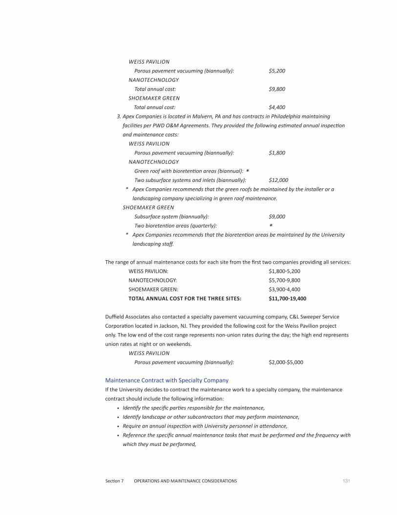
131Section 7 OPERATIONS AND MAINTENANCE CONSIDERATIONS
WEISS PAVILION
Porous pavement vacuuming (biannually): $5,200
NANOTECHNOLOGY
Total annual cost: $9,800
SHOEMAKER GREEN
Total annual cost: $4,400
3. Apex Companies is located in Malvern, PA and has contracts in Philadelphia maintaining
facilities per PWD O&M Agreements. They provided the following estimated annual inspection
and maintenance costs:
WEISS PAVILION
Porous pavement vacuuming (biannually): $1,800
NANOTECHNOLOGY
Green roof with bioretention areas (biannual): * Two subsurface systems and inlets (biannually): $12,000
* Apex Companies recommends that the green roofs be maintained by the installer or a
landscaping company specializing in green roof maintenance.
SHOEMAKER GREEN
Subsurface system (biannually): $9,000
Two bioretention areas (quarterly): ** Apex Companies recommends that the bioretention areas be maintained by the University
landscaping staff.
The range of annual maintenance costs for each site from the first two companies providing all services:
WEISS PAVILION: $1,800-5,200
NANOTECHNOLOGY: $5,700-9,800
SHOEMAKER GREEN: $3,900-4,400
TOTAL ANNUAL COST FOR THE THREE SITES: $11,700-19,400
Duffield Associates also contacted a specialty pavement vacuuming company, C&L Sweeper Service
Corporation located in Jackson, NJ. They provided the following cost for the Weiss Pavilion project
only. The low end of the cost range represents non-union rates during the day; the high end represents
union rates at night or on weekends.
WEISS PAVILION
Porous pavement vacuuming (biannually): $2,000-$5,000
Maintenance Contract with Specialty CompanyIf the University decides to contract the maintenance work to a specialty company, the maintenance
contract should include the following information:
• Identify the specific parties responsible for the maintenance,
• Identify landscape or other subcontractors that may perform maintenance,
• Require an annual inspection with University personnel in attendance,
• Reference the specific annual maintenance tasks that must be performed and the frequency with
which they must be performed,

132 A Stormwater Master Plan For the University of Pennsylvania
• Require the contractor to provide inspection, maintenance, and monitoring reports for each site
visit,
• Require the contractor to provide photographic documentation of all facilities at the start of the
contract, and before and after each maintenance operation.
Contact information for Maintenance CompaniesThe companies providing the above cost estimates can be contacted to obtain detailed cost proposals
for the maintenance of the nine PWD-approved projects.
Stormwater Maintenance LLC
Hunt Valley, MD
Theodore Scott
410-785-0875
www.stormwatermaintenance.com
Stormwater Solutions LLC
Philadelphia, PA
David Plante
215-869-2025
www.stormwatersolutions.biz
Apex Companies
Malvern, PA
David Miller
610-722-9050
www.apexcos.com
C & L Sweeper Service Corp.
Gabriel Vitale
Jackson, NJ
732-886-1940
www.sweeping.com
Additional firms specializing in stormwater management maintenance can be found at:
www.bmpclean.org.

Section 1 EXECUTIVE SUMMARY 133
Section 1 EXECUTIVE SUMMARY
Section 2 STORMWATER RUN-OFF FROM TODAY’S CAMPUS
Section 3 STORMWATER MANAGEMENT ON TODAY’S CAMPUS
Section 4 POTENTIAL STORMWATER MANAGEMENT PRACTICES FOR FUTURE PROJECTS
Section 5 FINDING SUSTAINABLE STORMWATER MANAGEMENT OPPORTUNITIES
Section 6 STORMWATER MANAGEMENT COSTS AND PWD FEES
Section 7 OPERATIONS AND MAINTENANCE CONSIDERATIONS
Section 8 LEGISLATION ISSUES AND FUNDING OPPORTUNITIES
Section 9 RECOMMENDATIONS
Section 10 APPENDICES
A. Representative Stormwater Management Details
B. Stormwater Management Model
C. References
D. Acknowledgements

134 A Stormwater Master Plan For the University of Pennsylvania
LEGISLATION ISSUES AND FUNDING OPPORTUNITIES
This section reviews the regulatory framework for stormwater management compliance and discusses
pending stormwater regulation changes which may impact future development on the Penn campus.
Potential sources of funding for stormwater management improvements are also reviewed.
Legislation IssuesCurrent LegislationThe City of Philadelphia instituted the Philadelphia Water Department’s (PWD) stormwater regulations
on January 1, 2006. These regulations set stormwater management criteria for new land development
and redevelopment projects that disturb more than 15,000 square feet of earth during their
construction (for certain watersheds in the City, the management criteria are required if more than
5,000 square feet is disturbed, but the 15,000 square foot trigger applies to the Penn campus). The
management criteria are generally described in Section 2 of this plan and more detailed information is
available in PWD’s Stormwater Management Guidance Manual, available at www.pwdplanreview.org/
StormwaterManual.aspx.
In September 2009, PWD submitted its Combined Sewer Overflow (CSO) Long Term Control Plan
Update (LTCPU) to the Pennsylvania Department of Environmental Protection (PADEP). Following
PWD’s negotiations with PADEP, the LTCPU was amended and then approved by PADEP in June 2011.
Known as the Green City, Clean Waters Program, the amended plan has a 25-year implementation
period during which the City aims to comply with the federal Environmental Protection Agency’s
National CSO Control Policy of 1994 and Clean Water Act of 1972.
Rather than attaining compliance solely through the construction of sewage treatment improvements,
the Green City, Clean Waters plan takes an innovative approach to seeking to reduce flows to the
existing treatment system through the construction of green stormwater infrastructure that will
significantly decrease the stormwater contribution to the CSO problem. By the end of the 25-year
period, PWD will have invested approximately $2.4 billion ($1.2 billion in 2009 dollars) in the largest
green stormwater infrastructure program ever implemented in the United States. The entire LTCPU
document is available online at www.phillywatersheds.org/ltcpu/.
The PWD stormwater regulations provide the stormwater management criteria for new private and
public construction projects that will help the City meet the commitment made to the Commonwealth
of Pennsylvania in the LTCPU agreement.
As noted above, the basis of the LTCPU is the federal Clean Water Act of 1972. The Act was updated
in 1990 and established the National Pollutant Discharge Elimination System (NPDES). Phase I of the
NPDES program required stormwater management permitting for construction sites over 5 acres in
area. Phase II of the NPDES program was signed into law in 1999 and reduced the permitting threshold
requirement to land development projects disturbing 1 acre or more. NPDES Phase II permits are still
required for current projects.

135Section 8 LEGISLATION ISSUES AND FUNDING OPPORTUNITIES
The Clean Water Act also requires each State to develop a list of impaired streams and rivers that do
not meet the State’s water quality standards. The State must set Total Maximum Daily Loads (TMDLs)
for various pollutants, representing the maximum amount of a given pollutant that a stream or river
can receive and still meet the State’s water quality standards. Because the vast majority of stormwater
runoff from the University’s campus is directed to sewage treatment plants via the City’s combined
sewer system, the University is not directly responsible for meeting the TMDL levels for the Schuylkill
River. However, as the steward of its campus environment, the University can reduce the burden on
the City’s sewage treatment infrastructure through implementation of green stormwater practices and
judicious use of fertilizers, herbicides, pesticides, and deicing agents, as discussed in this Master Plan.
This also applies to Penn Park, where a portion of the facility drains directly to the Schuylkill River.
At the state level, the Pennsylvania Stormwater Management Act of 1978 (commonly known as Act
167), requires counties to create watershed-level stormwater management plans. The Act also requires
individual municipalities within each Pennsylvania county to adopt ordinances to implement the plans.
In Philadelphia, Act 167 plans have been completed for the Darby-Cobbs Creek Watershed (2004) and
the Tookany/Tacony-Frankford Watershed (2008), but not for the portion of the Schuylkill River located
in Philadelphia. In 2008, the City signed an agreement with PADEP, committing to the development of
a city-wide Act 167 planning process. According to Section 1.2.4.2 of the LTCPU document, the city-
wide plan will be largely based on PWD’s Stormwater Regulations. To date, Act 167 plans have been
initiated for the Pennypack Creek Watershed (2008), the Poquessing Creek Watershed (2009), and the
Wissahickon Creek Watershed (2010), but the LTCPU document does not provide a date of completion
for the entire city.
Future Changes to Legislation and Impacts to Development There are several potential changes to the existing legislation that could impact future development on
the University’s campus.
As mentioned above, new land development and redevelopment projects on the campus must
comply with the PWD stormwater regulations if they disturb more than 15,000 square feet of earth.
According to Section 1.2.4.2 of the LTCPU document, "PWD is considering modifications to the current
regulations, including to lower the threshold of disturbance that triggers the regulations for compliance
with the regulations from the current level of 15,000 square feet to a level of disturbance of 5,000
square feet." For reference, a typical parking area containing approximately 18 parking spaces with a
central two-way drive aisle occupies approximately 5,000 square feet.
The lowering of the earth disturbance threshold to 5,000 square feet would have broader implications
for future campus development. With this lower threshold, smaller building additions, parking
lot expansions, or pedestrian area restorations could trigger the requirement to comply with the
stormwater regulations and add project costs. Presumably, these smaller projects will be required to
complete infiltration testing, provide stormwater management practices, and be submitted for approval
through PWD’s Technical Review process. The testing, design, permitting, and construction costs will
136 A Stormwater Master Plan For the University of Pennsylvania
likely significantly increase for development of the campus. The LTCPU document does not indicate
when this lowered threshold might go into effect.
These smaller projects may lend themselves to the "banking" and "trading” approaches discussed
in Section 6 of the Master Plan. For example, a large Penn Connects construction project could have
the volume of its stormwater management system increased to capture roof runoff from an existing
adjacent building. Under a trading approach, that additional management of existing impervious
area could be used to offset the construction of a new parking area across the street from or in the
vicinity of the large project. The offsetting of impervious area would allow the small parking area
to be constructed without complying with the regulations. The construction of a larger subsurface
infiltration/detention system for the new and existing buildings in this example would likely be less
expensive than the construction of two separate systems, one for the new building and one for the new
parking lot across the street. As noted in Section 6, this approach does not advance the University’s
overall goal of increasing its management of stormwater runoff above existing levels, but there would
be no net increase in runoff.
The University’s original Request for Proposal (RFP) for this Master Plan included a request for an
assessment of the implications of managing 1.5 inches of runoff instead of the required 1 inch. The
RFP indicated that this assessment be based on "future recommendations from the Department
of Environmental Protection." Duffield Associates is aware (through its involvement in the ongoing
rewriting of the Pennsylvania Stormwater Best Management Practices Manual) that this possible
change is under consideration. Based on discussions with PADEP, the adoption of this new standard
does not appear to be imminent. The LTCPU agreement between PADEP and PWD does not appear to
give consideration to the regulations being revised to require this increased capture of runoff.
If PWD were to make the 1.5-inch requirement a part of the regulations, this would significantly
increase construction costs for stormwater practices as they would be required to capture and manage
50 percent more runoff. If the University is considering the oversizing of a proposed stormwater
management practice as part of a new development, Duffield Associates recommends that the
University focus on providing management of 1 inch of runoff from existing unmanaged impervious
surfaces near the project before considering management of 1.5 inches of runoff from the proposed
impervious areas. This approach will maximize the water quality improvements to the "first flush" of
runoff, the initial runoff volume at the start of a rain event that contains the highest concentration of
pollutants (as described in Section 2 of the Master Plan).
At the state level, it was mentioned above that PWD has committed to PADEP to create a city-wide
Act 167 plan. As noted in the LTCPU document, the city-wide plan would be largely based on
PWD’s Stormwater Regulations. Therefore, it is not anticipated that the Act 167 plan, once
completed, will create new stormwater management requirements for development projects on the
University’s campus.
As part of a recent revision to Pennsylvania’s Chapter 102 regulations, PADEP released an updated
Erosion and Sedimentation Pollution Control Program Manual in March 2012 that details the design
of erosion control devices for construction projects. The manual allows for the use of more updated
137Section 8 LEGISLATION ISSUES AND FUNDING OPPORTUNITIESY
technologies but does not place significant increased burden on site construction.
At the federal level, the Environmental Protection Agency has been working for several years on a
"National Rulemaking" initiative designed to provide more uniform stormwater regulations across the
country. The proposed changes have met significant opposition from the development community.
The EPA has acknowledged that developing the cost-benefit analysis associated with addressing
stormwater management on a nation-wide basis, taking into account the varying climates, soils, and
land development patterns, has been challenging.
According to EPA’s website, "EPA intends to propose a rule to strengthen the national stormwater
management program by June 10, 2013 and complete a final action by December 10, 2014." Until EPA
provides concise information on what regulatory changes may be coming to Pennsylvania, it is not
possible to determine what impacts the changes may have on future campus development.
Funding OpportunitiesThis section reviews current opportunities for funding to support the construction of green stormwater
management practices. Opportunities are reviewed at the local, state, and federal levels.
The Philadelphia Water Department (PWD) and the Philadelphia Industrial Development Corporation
(PIDC) created the Stormwater Management Incentive Program (SMIP) Grant to offer assistance to non-
residential PWD customers. PIDC is managing the program. PWD is funding the program and has the
final decision on which applicants receive funding. Funding provided by the program provides incentive
for property owners to implement green stormwater management practices that will reduce their
monthly PWD stormwater fees.
The first round of grant applications ended on March 31, 2012. However, based on discussions with
PIDC and PWD, Duffield Associates understands that the agencies intend to continue the program for
several years, depending on its success and the availability of funding. To be competitive in the grant
award process, the agencies recommend that the grant request range from $100,000 to $1,000,000.
This suggests that PWD and PIDC are seeking to support projects of considerable size that will provide
significant stormwater management benefits.
The grant funding may be applied towards the design and/or the construction of the proposed
stormwater practices, but the funding must be applied to practices that provide stormwater runoff
reduction, not general site improvements. The grant funding may be applied to new construction
projects but only towards stormwater management that exceeds the regulation requirements for the
proposed construction. For example, a subsurface infiltration/detention system for a new project could
be enlarged to manage runoff from adjacent unmanaged buildings or ground-level impervious areas.
The funding could be used for the design and construction of the expanded portion of the system.
The application process consists of submittal of a Concept Plan that provides information on the
proposed stormwater management practices. The grant awardees may receive a SMIP grant, a SMIP
grant supplemented by a low interest (1%) SMIP loan, or a low interest (1%) SMIP loan.

138 A Stormwater Master Plan For the University of Pennsylvania
Full details of the application process and the Project Evaluation Criteria may be viewed at:
www.phillywatersheds.org/what_were_doing.
In addition to the SMIP Grant program, PWD and PIDC provide an ongoing SMIP Loan program. Loans
ranging from $75,000 to $1,000,000 at a 1% fixed rate are available. The term of the loans is consistent
with the payback period of the stormwater management practices, up to 15 years. Applicants are
expected to make at least a 10% equity contribution. Applications are submitted to PIDC and are
reviewed on a quarterly basis (September 30, December 30, March 30, and June 30). A legal fee of
approximately $1,500-2,500 is payable upon settlement.
At the state level, PADEP’s Growing Greener II grant program has provided funding for stormwater-
related projects since 2005. In 2011, the Pennsylvania Environmental Council received a $200,000 grant
for a stormwater infiltration project in Philadelphia. From the list of 2011 grant awardees, it appears
that the Growing Greener program is putting most of its funding towards stream restoration and mining
reclamation projects. Information on the Growing Greener program can be viewed at:
www.depweb.state.pa.us/portal/server.pt/community/growing_greener/13958.
Another state entity, PENNVEST, the Pennsylvania Infrastructure Investment Authority, offers grants
through its Green Initiatives program and low-interest loans through its Clean Water State Revolving
Fund (CWSRF). The grants and loans are available to private and non-profit organizations. Supported
projects include green roofs, rain gardens, stormwater basins, and the planting of new trees along
corridors to reduce runoff from the adjacent impervious areas. Information on the PENNVEST funding
may be obtained at:
www.Portal.state.pa.us/portal/server.pt/community/about_us/9320.

Section 1 EXECUTIVE SUMMARY 139
Section 1 EXECUTIVE SUMMARY
Section 2 STORMWATER RUN-OFF FROM TODAY’S CAMPUS
Section 3 STORMWATER MANAGEMENT ON TODAY’S CAMPUS
Section 4 POTENTIAL STORMWATER MANAGEMENT PRACTICES FOR FUTURE PROJECTS
Section 5 FINDING SUSTAINABLE STORMWATER MANAGEMENT OPPORTUNITIES
Section 6 STORMWATER MANAGEMENT COSTS AND PWD FEES
Section 7 OPERATIONS AND MAINTENANCE CONSIDERATIONS
Section 8 LEGISLATION ISSUES AND FUNDING OPPORTUNITIES
Section 9 RECOMMENDATIONS
Section 10 APPENDICES
A. Representative Stormwater Management Details
B. Stormwater Management Model
C. References
D. Acknowledgements
140 A Stormwater Master Plan For the University of Pennsylvania
RECOMMENDATIONS
This Stormwater Master Plan is intended to serve as a planning tool to find opportunities for increasing
sustainability during new campus development or redevelopment projects. Stormwater planning
should be incorporated early into the planning process for all new projects. This approach mirrors that
of the Philadelphia Water Department (PWD), which requires that conceptual stormwater plans be
reviewed and approved by the City prior to being eligible for approval by the City’s Zoning Unit.
This section provides recommendations for integrating stormwater planning into the land use planning
process, as well as for advancing the University’s goal to increase the management of stormwater
runoff from currently unmanaged existing sites. These recommendations are presented below as
short-term (0 to 6 months), mid-term (6 months to 5 years), and long-term (beyond 5 years). Some
tasks may be accomplished within the specified timeframe, but many are intended to be adopted
indefinitely into the future.
Primary Stormwater Planning RecommendationsBefore discussing the short-, mid-, and long-term recommendations, several recommendations are
provided that should be considered as a basis for all stormwater planning on campus.
1. Pursue increased stormwater management on a block-by-block approach rather than a
campus-wide approach, as discussed in Sections 2 and 5 of the Master Plan. The block-by-
block approach is in keeping with a primary tenet of sustainable stormwater management:
to manage rainfall where it falls. The block-by-block diagrams in Section 5 depict potential
retrofit opportunities to provide stormwater management for currently unmanaged
impervious areas.
2. All new land development and redevelopment projects should strive to provide a 20 percent
reduction in impervious area as compared to pre-development conditions. By doing so, a
new project must only comply with the Water Quality requirement of the PWD stormwater
regulations. Such a project is thereby exempt from the Flood Control Requirement, which
typically requires large costly subsurface facilities and associated piping and inlets. Beyond
the cost considerations, the reduction of impervious area contributes to the primary goal
of PWD’s Green City, Clean Waters program: the reduction of the volume and frequency of
Combined Sewer Overflows (CSOs).
3. The primary stormwater management goal of all construction projects should be the
management of the first one inch of runoff from impervious surfaces for new and retrofit
projects, ideally via infiltration if soil conditions permit. The University’s original Request
for Proposal for this Master Plan requested an additional assessment of the implications
of managing the first 1.5 inches of runoff. If the University is considering the oversizing
of a proposed stormwater management practice as part of a new development, it is
recommended that the University focus on providing management of 1 inch of runoff from
existing unmanaged impervious surfaces near the project before considering management
of 1.5 inches of runoff from the proposed impervious areas. This approach will maximize the
water quality improvements to the "first flush" of runoff from the largest area of impervious

141Section 9 RECOMMENDATIONS
surface. The first flush is the initial runoff volume at the start of a rain event that contains the
highest concentration of pollutants (as described in Section 2).
4. The large projects envisioned in the Penn Connects and Penn Connects 2.0 plans may provide
the most significant opportunities for attaining meaningful stormwater management
practices. These projects also provide the opportunity for consideration of new stormwater
management technologies, such as those described in Section 4 of the Master Plan.
Considerable focus should be placed on conceptualizing innovative stormwater management
opportunities during the early planning phases of these projects, including an evaluation of
the potential for trading, shared systems and grant funding.
5. The University may want to consider increasing the storage capacity of stormwater
management facilities on new projects to accommodate the future rainleader connection of
adjacent existing buildings and runoff from impervious areas which are currently unmanaged.
This goal may be limited by the configuration of existing roof downspouts and existing
impervious area drainage inlets and piping in the vicinity of the proposed new projects.
However, identifying these opportunities will be most successful if considered early in the
planning process.
6. The University should consider stormwater management retrofits of existing buildings and
impervious as part of the University’s facility renewal and reinvestment program. When a
building roof is scheduled for repair or replacement, consider the addition of a green roof if
the existing structure will support it. When paved areas are scheduled for repaving or repair,
assess the feasibility of replacing the existing impervious pavement with porous pavement,
and/or consider the potential for adding subsurface or surface stormwater management
facilities to manage the runoff from these pavements.
7. The University may want to consider investing in green roofs as a signature feature on Penn’s
campus. The many stormwater benefits of green roofs have been discussed in the previous
sections of the master plan. While retrofitted green roofs often provide a lengthy rate-of-
return on the construction costs, green roofs on new buildings may provide cost savings by
reducing ground-level stormwater management facilities (which also saves land for other
uses), increasing lifecycles of roof membranes, and reducing heating and cooling costs.
As solar power technology continues to advance, competition for roof space may develop
between energy production in the form of solar panels and stormwater management in the
form of green roofs. Depending on the proposed building roof configuration, one practice may
be more practical than the other, but a roof accommodating both technologies is an option.
In certain configurations, PWD may give stormwater management credit and fee credit for
impervious solar panels that drain to the green roof portion of a roof.
8. The University should assess the feasibility and maintenance cost of installing porous
pavements for all new impervious areas as a way to reduce the need for subsurface
infiltration/detention systems. Even though PWD does not require infiltration testing for
porous pavement installations, Duffield Associates recommends testing for infiltration
practices to reduce the potential for system failure.
9. One of the simplest ways to reduce stormwater management requirements is to reduce

142 A Stormwater Master Plan For the University of Pennsylvania
impervious area. As part of its sustainability goals, the University should continue the
current policy to remove surface parking areas by more effective use of perimeter parking
structures. The Penn Connects plan envisions improvements to the campus’s bicycle and public
transportation infrastructure. Greater reliance on these more sustainable transportation
modes could ultimately lead to reduced impervious area on campus.
10. A diligent Operations and Maintenance Program should be established to protect the
investment in the stormwater management practices already constructed and planned. As
with any engineered system, periodic preventive maintenance will always be more cost-
effective than delaying maintenance until the system exhibits signs of impending failure. In
the case of an infiltrating stormwater practice, system failure would likely require complete
excavation and reconstruction of the facility in order for it to maintain compliance with PWD
stormwater regulations.
11. The University should specify the use of double-ring infiltrometers for all infiltration testing.
This is the methodology preferred by PWD and PADEP, and should provide the most reliable
information for infiltration system design. Based on the testing results from the new projects
constructed since 2006, the infiltration capacity of the campus’s soils are highly variable and
can only be accurately assessed through infiltration testing at the specific location and depth
of a proposed infiltration system.
Short-term Recommendations (0 to 6 Months)The following recommendations should be given top priority, either because they are critical to the
success of the University’s goal of increasing stormwater management, have immediate cost saving
implications, or, in the case of the first item, have an impending deadline for action.
1. The University should and obtain cost proposals for stormwater facility maintenance from
several companies specializing in these operations, as discussed in Section 7. Stormwater
facility maintenance requires specialized knowledge and equipment. Using a private company
may be cost effective by reducing the training and equipment costs required to implement
an internally managed successful O&M program. At least one of the maintenance companies
referred to in Section 7 also manages the application process for the mandatory 4-year
renewals of PWD stormwater fee credits.
2. The University should verify that all applications have been submitted to and approved by
PWD for obtaining the stormwater fee credits for the projects constructed since 2006. If
applications have not been made, submit the necessary documentation to PWD to receive
the appropriate fee credit. The application process, while requiring an engineer’s seal, is a
fairly straightforward process and the initial verification could perhaps be performed by a
University intern.
3. The University should review the PWD billing information for all University properties. Duffield
Associates has found errors in the PWD data for other clients. If errors are discovered, submit
the necessary documentation to PWD to correct the discrepancies and lower the PWD fees for
the parcels in question. Ownership verification and ground-truthing of the existing impervious
areas shown for each parcel on PWD’s billing website could perhaps be performed by a
University intern.
4. The University should continue to meet regularly with PWD to discuss ongoing stormwater

143Section 9 RECOMMENDATIONS
planning issues on campus. Additional topics of discussion might include banking and trading
of impervious areas (as described in Section 5), potential funding opportunities, and pending
legislation changes that might impact future development on campus.
Mid-term Recommendations (6 Months to 5 Years)The following recommendations should be given secondary priority. They could be initiated before
the six month timeframe, but these items do not have immediate significant cost implications to
the University.
1. The block-by-block diagrams in Section 5 of the Master Plan indicate which existing buildings
may be potential candidates for green roof retrofitting. The analysis of each of the existing
buildings was limited to a determination of building ownership and the general configuration
of the building’s roof. The next step is for the University to develop a priority listing of
potential green roof retrofit candidates so that these can be evaluated as funding becomes
available, or as the existing roofs become due for roof replacement or repairs. More detailed
information on assessing green roof retrofit feasibility is provided at the end of this section.
2. At the same time that existing buildings are being evaluated for their green roof retrofitting
feasibility, the potential to disconnect existing roof downspouts from a direct connection to
the City’s combined sewer system and redirect them to new subsurface infiltration/detention
facilities should also be assessed. As a separate study, Duffield Associates reviewed the
available plans for the University’s buildings and mapped the water, storm and sanitary sewer
lateral locations. The storm sewer laterals for many existing buildings are directed towards
the combined sewers located in the adjacent City streets. In these situations, it may be
difficult to redirect the laterals to new subsurface stormwater systems located in the block’s
interior, unless plumbing adjustments can be made within the basements of the buildings.
Such an adjustment would require rerouting the roof drain lateral through a new location in
the building’s foundation, which may be difficult and costly.
3. As new projects are planned and designed over the next 5 years, the following green
stormwater practices should be considered as part of the overall stormwater management
strategy for each project: capture and reuse of stormwater rainfall, conversion of turf grass
areas to bioretention areas and meadow areas, and planting of new trees.
As discussed in Section 6, capture/reuse systems can have significant construction costs,
especially if water treatment is required for the intended use of the captured rainwater.
However, operations such as vehicle and equipment washing may not need treated water.
Captured rainwater may be used for landscaping, such as is occurring at Penn Park, but
PWD does not give stormwater management credit or fee credit for irrigation uses of
harvested rainwater.
Conversion of existing lawn areas to more sustainable vegetated landscapes such as
bioretention areas and meadow areas will reduce stormwater runoff. Once established, the
native vegetation planted in these areas will typically require less frequent maintenance than
the lawn areas they have replaced.
4. The University may want to gather the construction cost data for the stormwater
management practices built as part of the projects constructed since 2006. Typical
construction costs for various stormwater systems are provided in Section 6. However, an
144 A Stormwater Master Plan For the University of Pennsylvania
analysis of construction costs for the University’s projects may provide valuable cost-benefit
information for other projects.
5. As mentioned above, Duffield Associates completed a separate utility study that plotted
existing water, storm and sanitary sewer lateral locations. In addition, the University has
plotted the chilled water and steam lines across the campus. The University may want to
consider obtaining utility plans via the PA One Call System for all utilities located in the City
streets. PWD maintains excellent archived plan records for water, storm, and sanitary sewers.
While most of this information is in the form of hand-drawn plans, it has been converted to
digital format so would be easily digitized into the University’s master utility cad files. This
street utility information would allow assessment of the feasibility of cross-street transfers of
stormwater (from one block to the next) as discussed in the stormwater planning procedural
framework outlined in Section 5. This information would also be required for conceptual
planning of potential green street construction.
To complete the mapping of utilities located in the interiors of the campus’ city blocks, the
University may want to review available plans and plot the remaining utilities such as gas,
electric, and phone. This information would help identify potential conflicts with proposed
subsurface stormwater management facilities, as well as general utility planning for
new projects.
Long-term Recommendations (Beyond 5 Years)
The following recommendations should be considered once the short-term and mid-term
recommendations are addressed. These recommendations may provide the lengthiest return-on-
investment periods but can still advance the University’s goals of increased sustainability. Several of the
recommendations focus on integrating the goals of the Master Plan into the University’s curricula and
research efforts.
1. The University may want to explore potential "green street" development on campus
in conjunction with PWD and the City’s Streets Department. Liability issues associated
with directing potentially contaminated stormwater runoff from public streets onto the
University’s private property were briefly discussed in Section 5. If the University chooses
to pursue the creation of green streets on campus, its legal department should assess the
liability implications of this shared utility scenario. In addition to the sharing of design and
construction costs, agreements will need to be reached regarding responsibilities for the long-
term maintenance of shared facilities. The best candidates for green streets on campus will be
those streets with the fewest existing utilities, lower levels of vehicle usage, and higher levels
of pedestrian traffic. Ideally, the existing soils will allow for infiltration, but street rights-of-
way often contain highly compacted soils.
2. The University may want to promote stormwater research in academic programs. This
research could be conducted in conjunction with PWD, PADEP, or other local, state, or
federal agencies.
3. The University might consider a program with more extensive monitoring and evaluation of
system performance than that required by PWD. Perhaps in collaboration with appropriate
academic programs, collected data could be used to evaluate critical design criteria for
145Section 9 RECOMMENDATIONS
various stormwater practices. For example, the detailed collection and analysis of rainfall data
and use of captured rainwater for irrigation water at Penn Park could improve the design of
other potential capture/reuse systems on campus.
Green Roof Retrofit Analysis GuidelinesAs mentioned under Mid-term Recommendation #1 above, the block-by-block diagrams in Section
5 of the Master Plan indicate which existing buildings may be potential candidates for green roof
retrofitting. The block-by-block analysis did not evaluate the structural design of the buildings or
consider the University’s future plans for the buildings. The following guidelines are suggested for
evaluating the structural capacity of existing buildings for green roof retrofitting feasibility.
1. The University should prepare an initial list of potential green roof retrofit candidates using
the block-by-block diagrams in Section 5 of the Master Plan. Buildings slated for impending
demolition or with known structural deficiencies should be eliminated from the list.
2. Some general guidelines for initially identifying existing buildings as "good candidates" and
"poor candidates" for green roof retrofits are provided here. This classification is based on
the evolution of structural design for buildings over the last century. Older buildings tend to
be overdesigned so that their structures are more likely to be able to support the additional
loading of the components of a green roof. Good candidates are typically older (pre-1950’s)
single- or multiple-story reinforced concrete buildings. Institutional buildings constructed from
the 1950’s through the 1970’s may also be good candidates. Modern one-story buildings are
typically poor candidates for green roof retrofitting. Modern building roofs constructed with
steel open-web joist roof framing are also poor candidates.
3. A typical 3-inch-thick extensive green roof in a saturated condition (i.e., following a rainfall
event) will add approximately 10 to 15 pounds per square foot to the building’s roof structure.
As recommended above, the University might consider creating green roofs intended for
public access. The use of a roof as public space typically adds 100 pounds per square foot to
the required loading of the roof structure. For this reason, older existing buildings may be able
to support a typical extensive green roof, but may not be able to support the load demands
for use of the roof as public space. New buildings can be designed to meet the higher loading
requirements for public access. Construction costs will be higher, though these are somewhat
offset by the less tangible benefits of creating a unique public gathering space that increases
usable green space on campus, and the preservation of ground-level space for other uses.
4. The most important factor contributing to a quick determination of green roof retrofit
feasibility is the existence of the original structural drawings for the building or, if the building
has been modified since construction, drawings that accurately depict the current conditions
of the building’s structure and roof. With these drawings, a structural engineer is able to
quickly complete an initial green roof feasibility analysis for a building. The University might
consider using an intern (with some structural engineering knowledge) to locate the original
structural drawings for the green roof retrofit candidate buildings from Penn’s Falcon drawing
database. Once the relevant drawings are collected for the retrofit candidate buildings, the
University could engage a structural engineer experienced in green roof retrofit analysis
to complete the initial evaluations of the structural capabilities of the selected buildings to
support a green roof.

146 A Stormwater Master Plan For the University of Pennsylvania
It is anticipated that the information presented in the Stormwater Master Plan will evolve over time
as the University’s plans for future development unfold, new stormwater management technologies
and techniques are created, and with the adoption of new stormwater regulations at all levels
of government. This Master Plan should be revisited in five years to respond to the University’s
development and to maximize the use of emerging state-of-the-art design methodologies for
sustainable stormwater management.

Section 1 EXECUTIVE SUMMARY 147
Section 1 EXECUTIVE SUMMARY
Section 2 STORMWATER RUN-OFF FROM TODAY’S CAMPUS
Section 3 STORMWATER MANAGEMENT ON TODAY’S CAMPUS
Section 4 POTENTIAL STORMWATER MANAGEMENT PRACTICES FOR FUTURE PROJECTS
Section 5 FINDING SUSTAINABLE STORMWATER MANAGEMENT OPPORTUNITIES
Section 6 STORMWATER MANAGEMENT COSTS AND PWD FEES
Section 7 OPERATIONS AND MAINTENANCE CONSIDERATIONS
Section 8 LEGISLATION ISSUES AND FUNDING OPPORTUNITIES
Section 9 RECOMMENDATIONS
Section 10 APPENDICES
A. Representative Stormwater Management Details
B. Stormwater Management Model
C. References
D. Acknowledgements

148 A Stormwater Master Plan For the University of Pennsylvania
APPENDIX A
Representative Stormwater Management DetailsThis appendix contains typical construction details for various green stormwater management
practices. All provided details, except for the green roof detail, were approved by PWD for projects
designed by Duffield Associates or LRSLA Studio.
A CD is included with the Master Plan containing AutoCAD 2012 and pdf files of the details.
These details are illustrative only, and are provided for general guidance. It is the responsibility of the
engineer to determine the applicability of these details to stormwater designs for particular projects
and sites, and modify them accordingly. Duffield Associates does not warrant the applicability of these
details to other sites or approval by the Philadelphia Water Department on other projects and is not
responsible for problems arising from the use of this information.

149Section 10 APPENDICES
DETAIL: GREEN ROOF SECTION, TYP.SCALE : N.T.S.
SEPARATION FABRIC
GROWTH MEDIA: DEPTHVARIES
DRAINAGE LAYER: GRANULARMATERIAL OR MANUFACTUREDSYSTEMTOP OF ROOF PROTECTIONSYSTEM INCLUDINGINSULATION, PROTECTIONBOARD, WATERPROOFING
NOTES:
1. TO OBTAIN CREDIT FOR ONE INCH OFSTORMWATER RUNOFF MANAGEMENT FROMTHE PHILADELPHIA WATER DEPARTMENT,THE GROWING MEDIA MUST HAVE AMINIMUM OF 3" THICKNESS.
2. AN IRRIGATION SYSTEM MAY BEINCORPORATED DEPENDING ON THE PLANTSELECTION.
DETAIL: GREEN ROOF SECTION, TYP.Scale: N.T.S.
Green RoofGreen roofs are best designed by engineers or architects experienced in their design. Section 4
of the Master Plan includes information on a variety of manufactured green roof systems. Most
manufacturers will provide design assistance and some will provide installation and maintenance
services.
The attached detail depicts the typical components of a green roof and is not intended to represent an
actual design.
It is critical that the roof’s waterproof membrane be in excellent condition before installing the green
roof components. Retrofitting a green roof to an existing building will be most cost-effective if installed
when the roof membrane is scheduled for replacement.
A green roof with a growing medium of 3 inch minimum thickness meets the Water Quality
Requirement of the Philadelphia Water Department’s (PWD) Stormwater Regulations. It is considered
to provide the necessary management for the first inch of runoff and is eligible for stormwater fee
credits. The green roof can also contribute to the 20 percent reduction of existing impervious area that
exempts the project from the Flood Control Requirements.
Additional information on green roofs can be found in the PWD’s Stormwater Management
Guidance Manual.
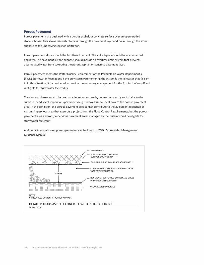
150 A Stormwater Master Plan For the University of Pennsylvania
Porous PavementPorous pavements are designed with a porous asphalt or concrete surface over an open-graded
stone subbase. This allows rainwater to pass through the pavement layer and drain through the stone
subbase to the underlying soils for infiltration.
Porous pavement slopes should be less than 5 percent. The soil subgrade should be uncompacted
and level. The pavement’s stone subbase should include an overflow drain system that prevents
accumulated water from saturating the porous asphalt or concrete pavement layer.
Porous pavement meets the Water Quality Requirement of the Philadelphia Water Department’s
(PWD) Stormwater Regulations if the only stormwater entering the system is the rainwater that falls on
it. In this situation, it is considered to provide the necessary management for the first inch of runoff and
is eligible for stormwater fee credits.
The stone subbase can also be used as a detention system by connecting nearby roof drains to the
subbase, or adjacent impervious pavements (e.g., sidewalks) can sheet flow to the porous pavement
area. In this condition, the porous pavement area cannot contribute to the 20 percent reduction of
existing impervious area that exempts a project from the Flood Control Requirements, but the porous
pavement area and roof/impervious pavement areas managed by the system would be eligible for
stormwater fee credit.
Additional information on porous pavement can be found in PWD’s Stormwater Management
Guidance Manual.
VARIES
FINISH GRADE
POROUS ASPHALT CONCRETESURFACE COURSE 2 1/2"
NON-WOVEN GEOTEXTILE (BOTTOM AND SIDES)MIRAFI 160N OR EQUIVALENT
UNCOMPACTED SUBGRADE
AGGREGATE (AASHTO #3)CLEAN-WASHED UNIFORMLY GRADED COARSE
CHOKER COURSE: AASHTO #57 AGGREGATE 2"
NOTE:NO RECYCLED CONTENT IN POROUS ASPHALT.
DETAIL: POROUS ASPHALT CONCRETEWITH INFILTRATION BED
SCALE : N.T.S.
DETAIL: POROUS ASPHALT CONCRETE WITH INFILTRATION BEDScale: N.T.S.
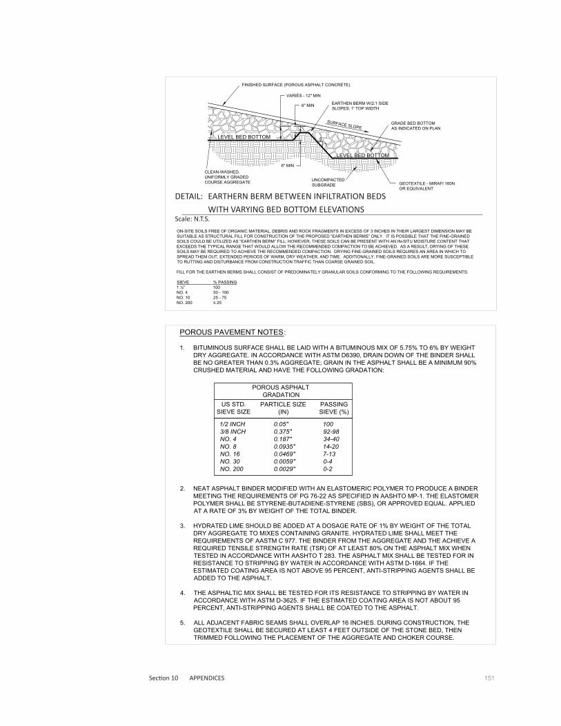
151Section 10 APPENDICES
POROUS PAVEMENT NOTES:
1. BITUMINOUS SURFACE SHALL BE LAID WITH A BITUMINOUS MIX OF 5.75% TO 6% BY WEIGHTDRY AGGREGATE. IN ACCORDANCE WITH ASTM D6390, DRAIN DOWN OF THE BINDER SHALLBE NO GREATER THAN 0.3% AGGREGATE; GRAIN IN THE ASPHALT SHALL BE A MINIMUM 90%CRUSHED MATERIAL AND HAVE THE FOLLOWING GRADATION:
2. NEAT ASPHALT BINDER MODIFIED WITH AN ELASTOMERIC POLYMER TO PRODUCE A BINDERMEETING THE REQUIREMENTS OF PG 76-22 AS SPECIFIED IN AASHTO MP-1. THE ELASTOMERPOLYMER SHALL BE STYRENE-BUTADIENE-STYRENE (SBS), OR APPROVED EQUAL. APPLIEDAT A RATE OF 3% BY WEIGHT OF THE TOTAL BINDER.
3. HYDRATED LIME SHOULD BE ADDED AT A DOSAGE RATE OF 1% BY WEIGHT OF THE TOTALDRY AGGREGATE TO MIXES CONTAINING GRANITE. HYDRATED LIME SHALL MEET THEREQUIREMENTS OF AASTM C 977. THE BINDER FROM THE AGGREGATE AND THE ACHIEVE AREQUIRED TENSILE STRENGTH RATE (TSR) OF AT LEAST 80% ON THE ASPHALT MIX WHENTESTED IN ACCORDANCE WITH AASHTO T 283. THE ASPHALT MIX SHALL BE TESTED FOR INRESISTANCE TO STRIPPING BY WATER IN ACCORDANCE WITH ASTM D-1664. IF THEESTIMATED COATING AREA IS NOT ABOVE 95 PERCENT, ANTI-STRIPPING AGENTS SHALL BEADDED TO THE ASPHALT.
4. THE ASPHALTIC MIX SHALL BE TESTED FOR ITS RESISTANCE TO STRIPPING BY WATER INACCORDANCE WITH ASTM D-3625. IF THE ESTIMATED COATING AREA IS NOT ABOUT 95PERCENT, ANTI-STRIPPING AGENTS SHALL BE COATED TO THE ASPHALT.
5. ALL ADJACENT FABRIC SEAMS SHALL OVERLAP 16 INCHES. DURING CONSTRUCTION, THEGEOTEXTILE SHALL BE SECURED AT LEAST 4 FEET OUTSIDE OF THE STONE BED, THENTRIMMED FOLLOWING THE PLACEMENT OF THE AGGREGATE AND CHOKER COURSE.
POROUS ASPHALTGRADATION
US STD.SIEVE SIZE
PARTICLE SIZE(IN)
PASSINGSIEVE (%)
1/2 INCH 0.05" 1003/8 INCH 0.375" 92-98NO. 4 0.187" 34-40NO. 8 0.0935" 14-20NO. 16 0.0469" 7-13NO. 30 0.0059" 0-4NO. 200 0.0029" 0-2
LEVEL BED BOTTOM
LEVEL BED BOTTOM
SURFACE SLOPE
FINISHED SURFACE (POROUS ASPHALT CONCRETE)
EARTHEN BERM W/2:1 SIDESLOPES; 1' TOP WIDTH
UNCOMPACTEDSUBGRADE
CLEAN-WASHED,UNIFORMLY GRADEDCOURSE AGGREGATE
VARIES - 12" MIN
6" MIN
GRADE BED BOTTOMAS INDICATED ON PLAN
6" MIN
GEOTEXTILE - MIRAFI 160NOR EQUIVALENT
ON-SITE SOILS FREE OF ORGANIC MATERIAL, DEBRIS AND ROCK FRAGMENTS IN EXCESS OF 3 INCHES IN THEIR LARGEST DIMENSION MAY BESUITABLE AS STRUCTURAL FILL FOR CONSTRUCTION OF THE PROPOSED “EARTHEN BERMS” ONLY. IT IS POSSIBLE THAT THE FINE-GRAINEDSOILS COULD BE UTILIZED AS “EARTHEN BERM” FILL; HOWEVER, THESE SOILS CAN BE PRESENT WITH AN IN-SITU MOISTURE CONTENT THATEXCEEDS THE TYPICAL RANGE THAT WOULD ALLOW THE RECOMMENDED COMPACTION TO BE ACHIEVED. AS A RESULT, DRYING OF THESESOILS MAY BE REQUIRED TO ACHIEVE THE RECOMMENDED COMPACTION. DRYING FINE-GRAINED SOILS REQUIRES AN AREA IN WHICH TOSPREAD THEM OUT, EXTENDED PERIODS OF WARM, DRY WEATHER, AND TIME. ADDITIONALLY, FINE-GRAINED SOILS ARE MORE SUSCEPTIBLETO RUTTING AND DISTURBANCE FROM CONSTRUCTION TRAFFIC THAN COARSE GRAINED SOIL.
FILL FOR THE EARTHEN BERMS SHALL CONSIST OF PREDOMINATELY GRANULAR SOILS CONFORMING TO THE FOLLOWING REQUIREMENTS:
SIEVE % PASSING1 ½” 100NO. 4 50 - 100NO. 10 25 - 75NO. 200 ≤ 25
DETAIL: EARTHEN BERM BETWEEN INFILTRATION BEDSWITH VARYING BED BOTTOM ELEVATIONS
SCALE : N.T.S.
DETAIL: EARTHERN BERM BETWEEN INFILTRATION BEDS
WITH VARYING BED BOTTOM ELEVATIONSScale: N.T.S.
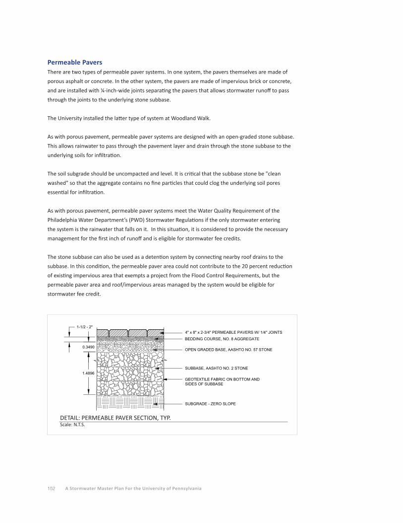
152 A Stormwater Master Plan For the University of Pennsylvania
Permeable PaversThere are two types of permeable paver systems. In one system, the pavers themselves are made of
porous asphalt or concrete. In the other system, the pavers are made of impervious brick or concrete,
and are installed with ¼-inch-wide joints separating the pavers that allows stormwater runoff to pass
through the joints to the underlying stone subbase.
The University installed the latter type of system at Woodland Walk.
As with porous pavement, permeable paver systems are designed with an open-graded stone subbase.
This allows rainwater to pass through the pavement layer and drain through the stone subbase to the
underlying soils for infiltration.
The soil subgrade should be uncompacted and level. It is critical that the subbase stone be "clean
washed" so that the aggregate contains no fine particles that could clog the underlying soil pores
essential for infiltration.
As with porous pavement, permeable paver systems meet the Water Quality Requirement of the
Philadelphia Water Department’s (PWD) Stormwater Regulations if the only stormwater entering
the system is the rainwater that falls on it. In this situation, it is considered to provide the necessary
management for the first inch of runoff and is eligible for stormwater fee credits.
The stone subbase can also be used as a detention system by connecting nearby roof drains to the
subbase. In this condition, the permeable paver area could not contribute to the 20 percent reduction
of existing impervious area that exempts a project from the Flood Control Requirements, but the
permeable paver area and roof/impervious areas managed by the system would be eligible for
stormwater fee credit.
DETAIL: PERMEABLE PAVEMENT SECTION, TYP.SCALE : N.T.S.
SUBBASE, AASHTO NO. 2 STONE
GEOTEXTILE FABRIC ON BOTTOM ANDSIDES OF SUBBASE
SUBGRADE - ZERO SLOPE
BEDDING COURSE, NO. 8 AGGREGATE
4" x 8" x 2-3/4" PERMEABLE PAVERS W/ 1/4" JOINTS
OPEN GRADED BASE, AASHTO NO. 57 STONE
1.4896
0.3490
1-1/2 - 2"
DETAIL: PERMEABLE PAVER SECTION, TYP.Scale: N.T.S.
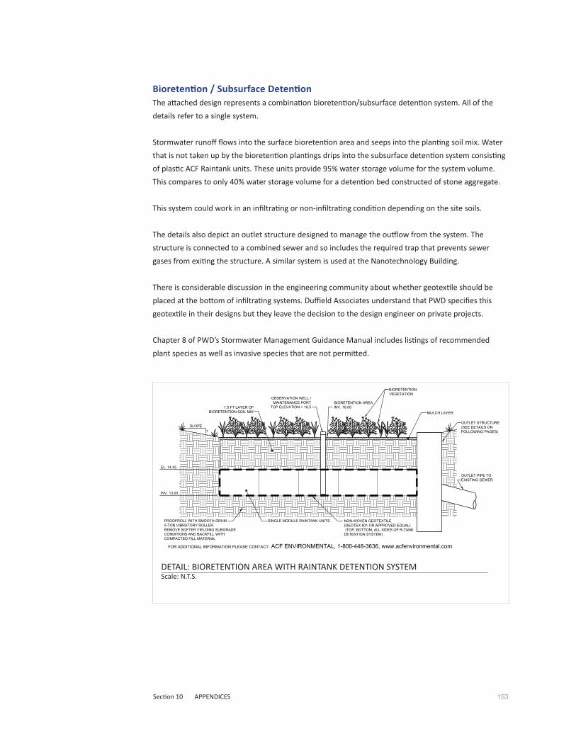
153Section 10 APPENDICES
Bioretention / Subsurface DetentionThe attached design represents a combination bioretention/subsurface detention system. All of the
details refer to a single system.
Stormwater runoff flows into the surface bioretention area and seeps into the planting soil mix. Water
that is not taken up by the bioretention plantings drips into the subsurface detention system consisting
of plastic ACF Raintank units. These units provide 95% water storage volume for the system volume.
This compares to only 40% water storage volume for a detention bed constructed of stone aggregate.
This system could work in an infiltrating or non-infiltrating condition depending on the site soils.
The details also depict an outlet structure designed to manage the outflow from the system. The
structure is connected to a combined sewer and so includes the required trap that prevents sewer
gases from exiting the structure. A similar system is used at the Nanotechnology Building.
There is considerable discussion in the engineering community about whether geotextile should be
placed at the bottom of infiltrating systems. Duffield Associates understand that PWD specifies this
geotextile in their designs but they leave the decision to the design engineer on private projects.
Chapter 8 of PWD’s Stormwater Management Guidance Manual includes listings of recommended
plant species as well as invasive species that are not permitted.
MULCH LAYER
OBSERVATION WELL /MAINTENANCE PORT
TOP ELEVATION = 16.5
SLOPE1
BIORETENTIONVEGETATION
SINGLE MODULE RAINTANK UNITS
1.5 FT LAYER OFBIORETENTION SOIL MIX
FOR ADDITIONAL INFORMATION PLEASE CONTACT: ACF ENVIRONMENTAL, 1-800-448-3636, www.acfenvironmental.com
NON-WOVEN GEOTEXTILE(GEOTEX 801 OR APPROVED EQUAL) (TOP, BOTTOM, ALL SIDES OF R-TANKDETENTION SYSTEM)
INV. 13.00
PROOFROLL WITH SMOOTH-DRUM5-TON VIBRATORY ROLLER.REMOVE SOFTER YIELDING SUBGRADECONDITIONS AND BACKFILL WITHCOMPACTED FILL MATERIAL
BIORETENTION AREAINV. 16.00
DETAIL: BIORETENTION AREA WITH RAINTANKDETENTION SYSTEM
SCALE : N.T.S.
EL. 14.45
OUTLET STRUCTURE(SEE DETAILS ONFOLLOWING PAGES)
OUTLET PIPE TOEXISTING SEWER
DETAIL: BIORETENTION AREA WITH RAINTANK DETENTION SYSTEM Scale: N.T.S.

154 A Stormwater Master Plan For the University of Pennsylvania
THREADED END CAP WITH ORIFICE(SEE SECTION C-C)
PWD INLET TRAP
OUTLET PIPETO EXISTINGCOMBINED
SEWER
RAINTANKDETENTION
SYSTEM
MODIFIED HIGHWAY GRATEINLET BOX (6' INLET)(SEE PWD STANDARDCATCH BASIN DETAIL FOR TYPICALCONSTRUCTION DETAILS)
NEENAH INLET GRATER-3247-2D
CONCRETE WEIR3
4" STEEL PLATE (26.5"x50.25")INSTALLED IN INLET GRATE FRAME
PLAN VIEW
CC
A
A
8" SOLIDHDPE
15" DIP
PWD STEEL HIGHWAYGRATE INLET FRAME(FLANGE ON ALL 4 SIDES)
24" WIDE X 16" HIGHOPENING INV. 13.00
(STRUCTURE BUTTEDAGAINST RAINTANK
DETENTION SYSTEM,CUT GEOTEXTILE AWAY
FROM OPENING
B
B
PLAN OFCONCRETESTRUCTURE
6'-2 3/4"
2'-2 3/4"
8" (TYP.)
DETAIL: OUTLET CONTROL STRUCTURE ANDSUBSURFACE DETENTION SYSTEM
SCALE : N.T.S.DETAIL: OUTLET CONTROL STRUCTURE AND SUBSURFACE DETENTION SYSTEMScale: N.T.S.
DETAIL: BIORETENTION AREA WITH RAINTANKDETENTION SYSTEM
SCALE : N.T.S.
MATERIALPLANTINGS
PLANTING SOIL**(36.0" DEEP)
MULCH (3"DEEP)
GEOTEXTILE
NOTES
USDA SOIL TYPES LOAMY SAND,SANDY LOAM OR LOAMpH 6.5-7.5 SALTS <500ppmMg 35 lb/ac CEC 8-25 cmd/kgPo 75 lb/ac K 85 lb/ac
MINIMUM PERMEABILITY OF 110 GPM/SF
SPECIFICATION(SEE PWD STORMWATER GUIDANCE MANUALFOR ACCEPTABLE PLANT SPECIES)
SAND 33%MULCH 33%PEAT 33%
TRIPLE-SHREDDED HARDWOOD (AGED 6 MONTHS)
GEOTEX 801 OR EQUIVALENT
SIZEN/A
N/A
N/A
N/A
SOIL MATERIAL SPECIFICATIONS FOR BIORETENTION AREA
DETAIL: BIORETENTION AREA WITH RAINTANK DETENTION SYSTEM Scale: N.T.S.

155Section 10 APPENDICES
DETAILS: OUTLET CONTROL STRUCTURE AND SUBSURFACE DETENTION SYSTEMScale: N.T.S.
DETAIL: OUTLET CONTROL STRUCTURE ANDSUBSURFACE DETENTION SYSTEM
SCALE : N.T.S.
SECTION A-A
INV. 9.70
OPENING FOR 8"SOLID HDPE PIPE
INV.13.00
24" WIDE X 16" HIGHOPENING BUTTED
AGAINST RAINTANKDETENTION SYSTEM
(CUT GEOTEXTILE AWAYFROM OPENING)
EL. 15.93
8" SOLID HDPE PIPEINV. 13.00
SECTION A-A
DETAIL: OUTLET CONTROL STRUCTURE ANDSUBSURFACE DETENTION SYSTEM
SCALE : N.T.S.
6" 2A STONE
COMPACTED SUBGRADE(UNDER STRUCTURE ONLY)
NEENAH GRATET.G.= 16.60
34" STEEL PLATE
30"
6" THICK CONCRETEWEIR (FULL WIDTH
OF INLET BOX) EL. 15.00
SECTION B-B
INV. 9.70
PWD INLET TRAP(SEE PWD STANDARD DETAIL)
15" RCP OUTLET PIPE
PWD STEEL HIGHWAY GRATEINLET FRAME(FLANGE ON ALL 4 SIDES)
INV.13.00
INV. 12.35
EL. 15.93
8" (TYP.)
FILL THIS SIDE OF WEIR WITHCONCRETE TO INV. 13.00AFTER STRUCTURE HAS
BEEN INSTALLED IN FIELD
SECTION B-B

156 A Stormwater Master Plan For the University of Pennsylvania
THREADED END PLUGW RECESSED HANDLE
DRILLED OFIFICE OPENING(DIMENSION VARIES)
DUAL WALL CLEANOUTNYLOPLAST DWG#0874AG OR AS REQ.FOR PIPE SIZES
TO BE SET IN PWD INLETWITH RECESSEDCONTROL STRUCTURE
DETAIL: SLOW-RELEASEORIFICE
SCALE : N.T.S.
DETAIL: SLOW-RELEASE ORIFICEScale: N.T.S.
MAINTENANCE PORT
THIS PORT IS USED TO PUMP WATER INTO THESYSTEM AND RE-SUSPEND ACCUMULATEDSEDIMENT SO THAT IT MAY BE PUMPED OUT.MINIMUM REQUIRED MAINTENANCE INCLUDESA QUARTERLY INSPECTION DURING THE FIRSTYEAR OF OPERATION AND A YEARLYINSPECTION THEREAFTER. FLUSH AS NEEDED.
FRAME AND COVER (WATERTIGHT SCREW CAP)
NOTCH BOTTOM OF PIPE(SEE PIPE NOTCHINGPATTERN DETAIL)
BIORETENTION AREAGROUND SURFACE
12" DIA. SOLID PVCMAINTENANCE PORT
PIPE NOTCHINGPATTERN DETAIL
6"-10" NOTCHES CUT INSHADED AREAS
NON-CORROSIVE HOSE CLAMP
GEOTEXTILE
NON-CORROSIVE SOLID PLATEPLASTIC, SLATE OREQUIVALENT (18"x18")
BIORETENTIONSOIL MIX
RAINTANKUNITS
DETAIL: RAINTANK OBSERVATION WELL /MAINTENANCE PORT
SCALE : N.T.S.
DETAIL: RAINTANK OBSERVATION WELL/ MAINTENANCE PORTScale: N.T.S.
DETAIL: OUTLET CONTROL STRUCTURE AND SUBSURFACE DETENTION SYSTEMSCALE : N.T.S.
EXISTING3'-6" x 2'-4"
BRICKCOMBINED
SEWER
SADDLE CONNECTIONAPPROX. TOP OF SEWER EL. 9.0
(SEE PWD STANDARD DETAIL)
NON-WOVEN GEOTEXTILE(GEOTEX 801 OR APPROVED EQUAL)
(TOP, BOTTOM, ALL SIDES OF RAINTANKDETENTION SYSTEM)
6" 2A STONE
COMPACTED SUBGRADE(UNDER STRUCTURE ONLY)
INV EL= 9.70
8" SOLID HDPE
EL. 15.93
PWD STEEL HIGHWAYGRATE INLET FRAME
RIM=16.60(FLANGE ON ALL 4 SIDES)
SECTION C-C
DRILL 112 -INCH DIAMETER
HOLE IN CENTER OFTHREADED END CAP(ORIFICE INV. 13.25)
1" MIN. CLEARANCE. SEALWITH NON-SHRINK GROUT
OUTLET PIPE TO EXISTINGSEWER 48 LF 15" RCP @MIN. 0.020 FT/FTINV. OUT 12.35
BIORETENTION AREAINV. 16.00
1.5 FT BIORETENTIONSOIL MIX
RAINTANKDETENTION SYSTEM
(300 SINGLE UNITS)
INV. 13.00
INV. 13.00PWD INLET TRAP(SEE PWD STANDARD DETAIL)
EL. 14.45
34" STEEL PLATE
IF INFILTRATING:UNCOMPACTED SUBGRADE
IF NOT INFILTRATING:PROOFROLL WITH SMOOTH-DRUM 5-TON
VIBRATORY ROLLER.REMOVE SOFTER YIELDING SUBGRADE
CONDITIONS AND BACKFILL WITHCOMPACTED FILL MATERIAL
7.5" (MIN.)
DETAIL: OUTLET CONTROL STRUCTURE AND SUBSURFACE DETENTION SYSTEMScale: N.T.S.
157Section 10 APPENDICES
APPENDIX B
Stormwater Management ModelIn order to simulate stormwater runoff conditions at the Penn campus, a stormwater model was
created to include the study area within the Request for Proposal. The first step in setting up the
stormwater model involved obtaining information from the City of Philadelphia, including public right-
of-way information and the locations of the City’s combined sewers. These items were incorporated
into an AutoCAD drawing of the Penn campus. Drainage areas were then delineated based on blocks
and likely connection points with the public sewer system. A total of 99 drainage areas were delineated.
Within each drainage area, breakdowns for roof and ground level impervious, as well as pervious area
coverage were determined using the AutoCAD drawing along with aerial photography. Public rights-of-
way were excluded from the analysis.
Based on the above evaluation, square footage of the existing impervious and pervious areas within the
Study Area were determined, as follows:
• Total Building Impervious Area = 4,051,341 sf
• Total Ground Impervious Area = 3,787,248 sf
• Total Impervious Area = 7,838,589 sf
• Total Pervious Area = 3,119,035 sf
A breakdown of each drainage area and its corresponding coverage can be found in the Penn Drainage
Area table in this section. Porous pavement and green roof areas were considered impervious in this
part of the analysis.
Once the physical characteristics of the study area were determined, this information was then input
into an urban hydrology and hydraulics program called Storm Water Management Model or SWMM.
This software was developed by the United States Environmental Protection Agency (EPA) in 1971,
and has since undergone several major upgrades. The current edition, Version 5 was used for this
project. The hydrology component of SWMM examines a collection of drainage areas divided into
impervious and pervious areas that receive precipitation and generates the runoff and estimated
pollutant loads for these areas. The routing portion of SWMM transports this runoff through the
stormwater management conveyance pipes (and channels, pumps, etc. where applicable). SWMM
tracks and reports the quantity and quality of runoff generated within each subcatchment during a
simulation period. Detailed information for green stormwater infrastructure, such as porous pavement,
bioretention, infiltration basins, and green roofs, can be input into the program to determine their
effectiveness. This program is publicly available and can be downloaded from the EPA website
(http://www.epa.gov/nrmrl/wswrd/wq/models/swmm/#Downloads).
The SWMM file in this section was set up to represent current land use conditions on campus. This
model should be updated as cover conditions change and new stormwater management practices
are implemented on the campus. The intent of the program is to provide a representation of the
stormwater runoff on the Penn campus as it functions in connection with the City’s sewer system.
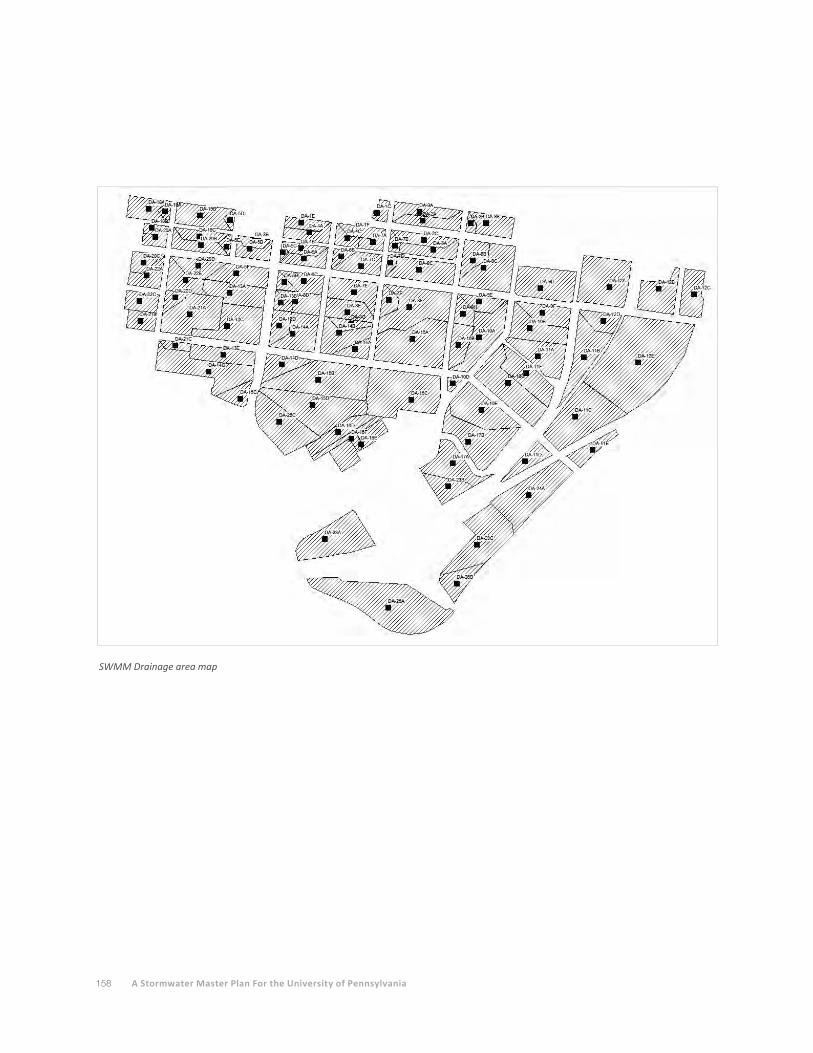
158 A Stormwater Master Plan For the University of Pennsylvania
SWMM Drainage area map
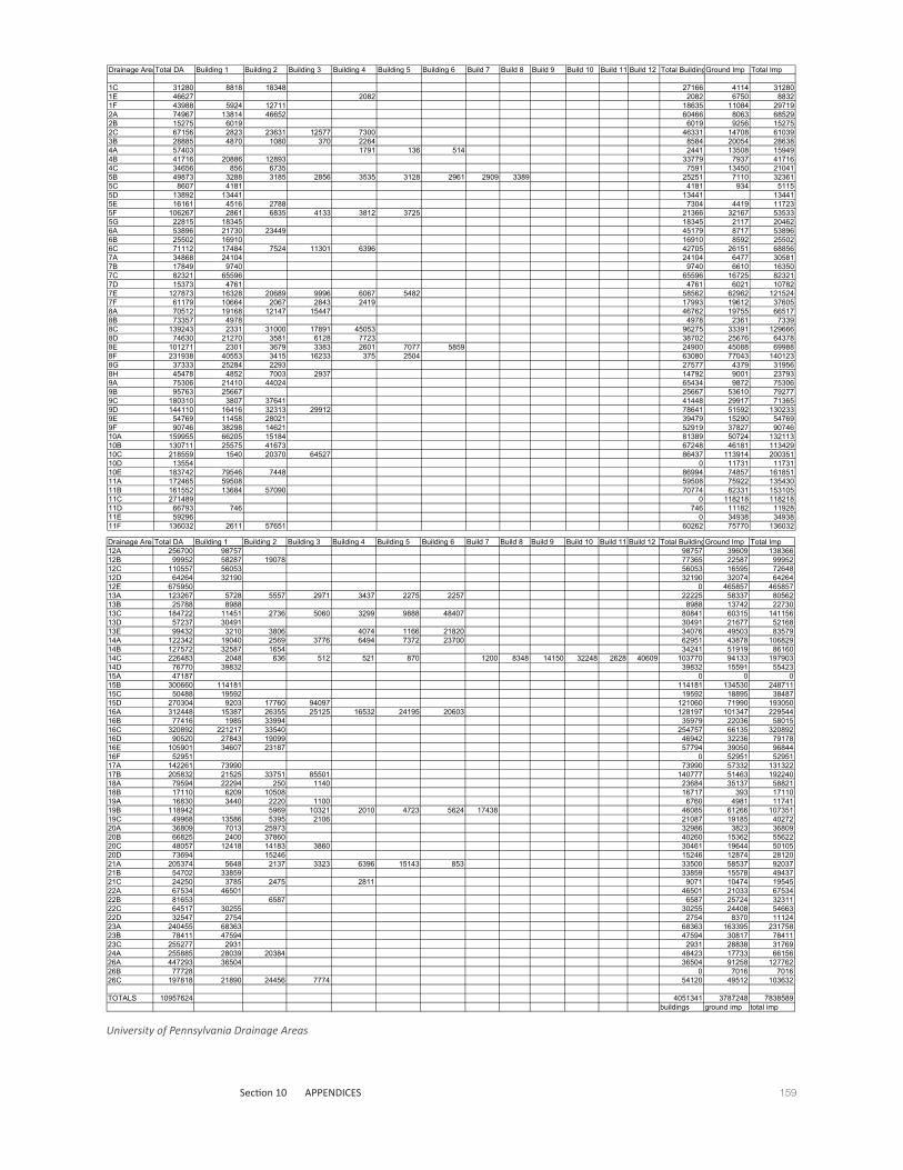
159Section 10 APPENDICES
Penn Drainage Areas
Drainage AreaTotal DA Building 1 Building 2 Building 3 Building 4 Building 5 Building 6 Build 7 Build 8 Build 9 Build 10 Build 11 Build 12 Total BuildingGround Imp Total Imp
1C 31280 8818 18348 27166 4114 312801E 46627 2082 2082 6750 88321F 43988 5924 12711 18635 11084 297192A 74967 13814 46652 60466 8063 685292B 15275 6019 6019 9256 152752C 67156 2823 23631 12577 7300 46331 14708 610393B 28885 4870 1080 370 2264 8584 20054 286384A 57403 1791 136 514 2441 13508 159494B 41716 20886 12893 33779 7937 417164C 34656 856 6735 7591 13450 210415B 49873 3288 3185 2856 3535 3128 2961 2909 3389 25251 7110 323615C 8607 4181 4181 934 51155D 13892 13441 13441 134415E 16161 4516 2788 7304 4419 117235F 106267 2861 6835 4133 3812 3725 21366 32167 535335G 22815 18345 18345 2117 204626A 53896 21730 23449 45179 8717 538966B 25502 16910 16910 8592 255026C 71112 17484 7524 11301 6396 42705 26151 688567A 34868 24104 24104 6477 305817B 17849 9740 9740 6610 163507C 82321 65596 65596 16725 823217D 15373 4761 4761 6021 107827E 127873 16328 20689 9996 6067 5482 58562 62962 1215247F 61179 10664 2067 2843 2419 17993 19612 376058A 70512 19168 12147 15447 46762 19755 665178B 73357 4978 4978 2361 73398C 139243 2331 31000 17891 45053 96275 33391 1296668D 74630 21270 3581 6128 7723 38702 25676 643788E 101271 2301 3679 3383 2601 7077 5859 24900 45088 699888F 231938 40553 3415 16233 375 2504 63080 77043 1401238G 37333 25284 2293 27577 4379 319568H 45478 4852 7003 2937 14792 9001 237939A 75306 21410 44024 65434 9872 753069B 95763 25667 25667 53610 792779C 180310 3807 37641 41448 29917 713659D 144110 16416 32313 29912 78641 51592 1302339E 54769 11458 28021 39479 15290 547699F 90746 38298 14621 52919 37827 9074610A 159955 66205 15184 81389 50724 13211310B 130711 25575 41673 67248 46181 11342910C 218559 1540 20370 64527 86437 113914 20035110D 13554 0 11731 1173110E 183742 79546 7448 86994 74857 16185111A 172465 59508 59508 75922 13543011B 161552 13684 57090 70774 82331 15310511C 271489 0 118218 11821811D 66793 746 746 11182 1192811E 59296 0 34938 3493811F 136032 2611 57651 60262 75770 136032
Penn Drainage Areas
Drainage AreaTotal DA Building 1 Building 2 Building 3 Building 4 Building 5 Building 6 Build 7 Build 8 Build 9 Build 10 Build 11 Build 12 Total BuildingGround Imp Total Imp12A 256700 98757 98757 39609 13836612B 99952 58287 19078 77365 22587 9995212C 110557 56053 56053 16595 7264812D 64264 32190 32190 32074 6426412E 675950 0 465857 46585713A 123267 5728 5557 2971 3437 2275 2257 22225 58337 8056213B 25788 8988 8988 13742 2273013C 184722 11451 2736 5060 3299 9888 48407 80841 60315 14115613D 57237 30491 30491 21677 5216813E 99432 3210 3806 4074 1166 21820 34076 49503 8357914A 122342 19040 2569 3776 6494 7372 23700 62951 43878 10682914B 127572 32587 1654 34241 51919 8616014C 226483 2048 636 512 521 870 1200 8348 14150 32248 2628 40609 103770 94133 19790314D 76770 39832 39832 15591 5542315A 47187 0 0 015B 300660 114181 114181 134530 24871115C 50488 19592 19592 18895 3848715D 270304 9203 17760 94097 121060 71990 19305016A 312448 15387 26355 25125 16532 24195 20603 128197 101347 22954416B 77416 1985 33994 35979 22036 5801516C 320892 221217 33540 254757 66135 32089216D 90520 27843 19099 46942 32236 7917816E 105901 34607 23187 57794 39050 9684416F 52951 0 52951 5295117A 142261 73990 73990 57332 13132217B 205832 21525 33751 85501 140777 51463 19224018A 79594 22294 250 1140 23684 35137 5882118B 17110 6209 10508 16717 393 1711019A 16830 3440 2220 1100 6760 4981 1174119B 118942 5969 10321 2010 4723 5624 17438 46085 61266 10735119C 49968 13586 5395 2106 21087 19185 4027220A 36809 7013 25973 32986 3823 3680920B 66825 2400 37860 40260 15362 5562220C 48057 12418 14183 3860 30461 19644 5010520D 73694 15246 15246 12874 2812021A 205374 5648 2137 3323 6396 15143 853 33500 58537 9203721B 54702 33859 33859 15578 4943721C 24250 3785 2475 2811 9071 10474 1954522A 67534 46501 46501 21033 6753422B 81653 6587 6587 25724 3231122C 64517 30255 30255 24408 5466322D 32547 2754 2754 8370 1112423A 240455 68363 68363 163395 23175823B 78411 47594 47594 30817 7841123C 255277 2931 2931 28838 3176924A 255885 28039 20384 48423 17733 6615626A 447293 36504 36504 91258 12776226B 77728 0 7016 701626C 197818 21890 24456 7774 54120 49512 103632
TOTALS 10957624 4051341 3787248 7838589buildings ground imp total imp
University of Pennsylvania Drainage Areas

160 A Stormwater Master Plan For the University of Pennsylvania
APPENDIX C
ReferencesCity of Philadelphia, Plumbing Code, Subcode "P" – Title 4 of the Philadelphia Code.
Green Infrastructure Foundation, Green Infrastructure: Projects, Performance and Policies, 2009.
Pennsylvania Department of Environmental Protection, Erosion and Sediment Pollution
Control Program Manual, Technical Guidance Number 363-2134-008, March 2012.
Pennsylvania Department of Environmental Protection, Pennsylvania Stormwater Best
Management Practices Manual, December 2006.
Philadelphia Water Department, Amended Green City Clean Waters, June 1, 2011.
Philadelphia Water Department, Stormwater Management Guidance Manual, Version 2.0.
Philadelphia Water Department, Water and Sewer Design Manual, 1995.
Sasaki Architects, PC, Penn Connects: A Vision for the Future, September 2006
WebsitesInterlocking Concrete Paver Institute: www.icpi.org
Low Impact Development Center: lid-stormwater.net/index.html
National Directory of Stormwater Contractors: www.bmpclean.org
Pennsylvania Department of Environmental Protection: www.elibrary.dep.state.pa.us
Philadelphia Water Department, Long Term Control Plan Update: www.phillywatersheds.org/what_
were_doing/documents_and_data/cso_long_term_control_plan
Philadelphia Water Department, Stormwater Management Guidance Manual:
www.phillywatersheds.org
StormwaterPA: www.stormwaterpa.org
U.S. Department of Agriculture (soil survey): websoilsurvey.nrcs.usda.gov/app/
U.S. Environmental Protection Agency:
Green infrastructure: water.epa.gov/infrastructure/greeninfrastructure
National Rulemaking: cfpub.epa.gov/npdes/stormwater/rulemaking.cfm

161Section 10 APPENDICES
APPENDIX D
AcknowledgementsUniversity of Pennsylvania - Facilities and Real Estate Services Marc Cooper, Project Manager
David Hollenberg, University Architect
Mark Kocent, Principal Planner
Robert Lundgren, University Landscape Architect
Ken Ogawa, Executive Director of Operations
Edward Sidor, Director of Design and Construction
Rebecca Weide, Landscape Planner
Walter Molishus, Operations Manager
Philadelphia Water Department Christine Marjoram
Vicki Lenoci
Glen Abrams
Duffield Associates Dan Meier
Susan Schriner
Deirdre Smith
Garry Brennan
LRSLA Studio, Inc. Karen Skafte
Frank Garnier
Lindsay High

![WSU Stormwater Master Plan Presentation 2 [Read-Only]](https://static.fdocuments.net/doc/165x107/6292ffb576f2dc26ce450088/wsu-stormwater-master-plan-presentation-2-read-only.jpg)