A SOFTWARE DEVELOPMENT IN GEAR · PDF fileA SOFTWARE DEVELOPMENT IN GEAR DESIGN M....
14
IOSR Journal of Mechanical and Civil Engineering (IOSR-JMCE) e- ISSN: 2278-1684, p-ISSN : 2320–334X PP 11-24 www.iosrjournals.org National Conference on Contemporary Approaches in Mechanical, 11 | Page Automobile and Building sciences-2014 Karpaga Vinayaga College Of Engineering & Technology A SOFTWARE DEVELOPMENT IN GEAR DESIGN M. Varatharajulu 1* , C. Loganathan 2 , K. Sivaramakrishnan 3 , R. Ayyappan 4* 1( Assistant Professor in Mechanical Engineering Department, 1,2 A. V. C. College of Engineering, Mannampandal, Mayiladuthurai,Tamilnadu, India). 2( Professor in Mechanical Engineering Department, 3 PG Scholar, Bharathiyar College of Engineering and Technology, Karaikal, Pondicherry, India.) 4( Senior Assistant Professor in Mechanical Engineering Department, 4 Aksheyaa College of Engineering, Pulidivakkam, Kancheepuram, Tamilnadu, India). ABSTRACT: Power or energy production is improbable everywhere due to various factors. For assorted applications, people depending source of power.This shows the need of transmission of power. Considering power transmission of mechanical drives, mesh type of drives are largely used to maintain the velocity ratio. Among mesh type, gears transmitting the power by means of successive engagement of their teeth. Design of gears either by manually or using computers has become a highly convoluted and comprehensive subject. Therefore, this study present a new method of how the gears can be designed and detailed with computer, previously, highlighting the design process which involves prolong time. A reliable software package developed with a help of Visual Basic 6.0 (VB) provides significant saving time reduces its convolution. Keywords- Power transmission, Design, Gear, Package, VB. 1. INTRODUCTION Gears are the drives which transmit power between the shafts by means of successive engagement of teeth. Among mesh type drive, gears are preferable when a constant speed ratio that is velocity ratio is desired and the distance between the shafts is comparatively small. Gears operate in pairs the smaller of the pair being called the pinion and the larger one the gear. Usually the pinion drives the gear and then it can act either as a speed reducer or speed accelerator and a torque converter. Generally gears are designed either by considering gear life or beam strength which is based on American Gear Manufactures Association (AGMA). Nordiana et al presented a new method of spur gear design detailed with computer aided design [1]. The presenters developed a package namely “Cadgear (2007)” which enhances the analytical and logical power of the designer of gear system. Varatharajulu and Rajendran developed a visual basic package to do the design of coupling and knuckle joint, which has the ability to reduce the burden of designer [2]. Researcher concluded that, the design of machine elements, transmission systems and jigs and fixture is possible by visual basic. This attempt concentrates on design of spur, helical, bevel and worm gear design based on two conventional techniques, with a help of computer aided design. A machine language is needed to make the computer to understand. Here coding written in visual basic, the computer processes these statements into visual basic language. 1.1 Software Development Visual Basic project explorer window has the tool box. From the tool box the label, text box and command box were dragged and then dropped in the appropriate position. Then code was written in the respective page according to the design parameters. Properties window helps to make the changes.
Transcript of A SOFTWARE DEVELOPMENT IN GEAR · PDF fileA SOFTWARE DEVELOPMENT IN GEAR DESIGN M....

IOSR Journal of Mechanical and Civil Engineering (IOSR-JMCE)
e- ISSN: 2278-1684, p-ISSN : 2320–334X
PP 11-24
www.iosrjournals.org
National Conference on Contemporary Approaches in Mechanical, 11 | Page
Automobile and Building sciences-2014
Karpaga Vinayaga College Of Engineering & Technology
A SOFTWARE DEVELOPMENT IN GEAR DESIGN
M. Varatharajulu1*
, C. Loganathan2, K. Sivaramakrishnan
3, R. Ayyappan
4*
1(Assistant Professor in Mechanical Engineering Department,
1,2A. V. C. College of Engineering, Mannampandal,
Mayiladuthurai,Tamilnadu, India). 2(
Professor in Mechanical Engineering Department,3PG Scholar, Bharathiyar College of Engineering and
Technology, Karaikal, Pondicherry, India.) 4(
Senior Assistant Professor in Mechanical Engineering Department, 4Aksheyaa College of Engineering,
Pulidivakkam, Kancheepuram, Tamilnadu, India).
ABSTRACT: Power or energy production is improbable everywhere due to various factors. For assorted
applications, people depending source of power.This shows the need of transmission of power. Considering power
transmission of mechanical drives, mesh type of drives are largely used to maintain the velocity ratio. Among mesh
type, gears transmitting the power by means of successive engagement of their teeth. Design of gears either by
manually or using computers has become a highly convoluted and comprehensive subject. Therefore, this study
present a new method of how the gears can be designed and detailed with computer, previously, highlighting the
design process which involves prolong time. A reliable software package developed with a help of Visual Basic 6.0
(VB) provides significant saving time reduces its convolution.
Keywords- Power transmission, Design, Gear, Package, VB.
1. INTRODUCTION
Gears are the drives which transmit power between the shafts by means of successive engagement of teeth.
Among mesh type drive, gears are preferable when a constant speed ratio that is velocity ratio is desired and the
distance between the shafts is comparatively small. Gears operate in pairs the smaller of the pair being called the
pinion and the larger one the gear. Usually the pinion drives the gear and then it can act either as a speed reducer or
speed accelerator and a torque converter. Generally gears are designed either by considering gear life or beam
strength which is based on American Gear Manufactures Association (AGMA).
Nordiana et al presented a new method of spur gear design detailed with computer aided design [1]. The
presenters developed a package namely “Cadgear (2007)” which enhances the analytical and logical power of the
designer of gear system. Varatharajulu and Rajendran developed a visual basic package to do the design of coupling
and knuckle joint, which has the ability to reduce the burden of designer [2]. Researcher concluded that, the design
of machine elements, transmission systems and jigs and fixture is possible by visual basic.
This attempt concentrates on design of spur, helical, bevel and worm gear design based on two
conventional techniques, with a help of computer aided design. A machine language is needed to make the computer
to understand. Here coding written in visual basic, the computer processes these statements into visual basic
language.
1.1 Software Development Visual Basic project explorer window has the tool box. From the tool box the label, text box and command box were
dragged and then dropped in the appropriate position. Then code was written in the respective page according to the
design parameters. Properties window helps to make the changes.

IOSR Journal of Mechanical and Civil Engineering (IOSR-JMCE)
e- ISSN: 2278-1684, p-ISSN : 2320–334X
PP 11-24
www.iosrjournals.org
National Conference on Contemporary Approaches in Mechanical, 12 | Page
Automobile and Building sciences-2014
Karpaga Vinayaga College Of Engineering & Technology
1.2. Sample source code
With the help of Visual Basic authors, developed the software which will reduce the complication in gear design.
Sample source code given, for reader‟s reference.
Public dbcon As New ADODB.Connection
Public rs As New ADODB.Recordset
Dim pi As Integer
Dim p As Double
Dim i As Double
Dim n1 As Double
Dim n2 As Double
Dim s1 As Double
Dim s2 As Double
Dim s3 As Double
Dim s4 As Double
Dim e1 As Double
Dim e2 As Double
Dim e As Double
Dim m1 As Double
Dim m2 As Double
Dim sai As Double
Dim saim As Double
Dim m As Double
Dim m3 As Double
Dim y As Double
Private Sub Combo3_Click()
If Combo3.Text = "Speed ratio, Pinion speed" Then
Label2.Visible = True
Label3.Visible = True
Label13.Visible = True
Text2.Visible = True
Text3.Visible = True
Label47.Visible = False
Text8.Visible = False
Label51.Visible = False
End If
If Combo3.Text = "Speed ratio, Gear speed" Then
Label2.Visible = True
Label47.Visible = True
Label51.Visible = True
Text2.Visible = True
Text8.Visible = True
Label3.Visible = False
Text3.Visible = False
Label13.Visible = False

IOSR Journal of Mechanical and Civil Engineering (IOSR-JMCE)
e- ISSN: 2278-1684, p-ISSN : 2320–334X
PP 11-24
www.iosrjournals.org
National Conference on Contemporary Approaches in Mechanical, 13 | Page
Automobile and Building sciences-2014
Karpaga Vinayaga College Of Engineering & Technology
End If
If Combo3.Text = "Pinion speed, Gear speed" Then
Label47.Visible = True
Text8.Visible = True
Label13.Visible = True
Label3.Visible = True
Text3.Visible = True
Label51.Visible = True
Text2.Visible = False
Label2.Visible = False
End If
End Sub
Private Sub Command3_Click()
Form17.Show
Me.Hide
End Sub
Private Sub Command_Click()
Me.PrintForm
End Sub
Private Sub Command4_Click()
Me.Hide
Form2.Show
End Sub
Private Sub Command5_Click()
End
End Sub
Private Sub Form_Load()
dbcon.ConnectionString = "Provider=Microsoft.Jet.OLEDB.4.0;Data Source=" + App.Path +
"\Database.mdb"
dbcon.Open
End Sub
Private Sub Combo1_Click()
rs.Open "select * from Table6 where Material = '" & Combo1.Text & "' ", dbcon, adOpenDynamic,
adLockOptimistic, -1
Text5.Text = rs.Fields(2)
Text6.Text = rs.Fields(1)
Text7.Text = rs.Fields(3)
rs.Close
End Sub
Private Sub Combo2_Click()
rs.Open "select * from Table6 where Material = '" & Combo2.Text & "' ", dbcon, adOpenDynamic,
adLockOptimistic, -1
Text9.Text = rs.Fields(2)
Text10.Text = rs.Fields(1)
IOSR Journal of Mechanical and Civil Engineering (IOSR-JMCE)
e- ISSN: 2278-1684, p-ISSN : 2320–334X
PP 11-24
www.iosrjournals.org
National Conference on Contemporary Approaches in Mechanical, 14 | Page
Automobile and Building sciences-2014
Karpaga Vinayaga College Of Engineering & Technology
Text11.Text = rs.Fields(3)
rs.Close
End Sub
Private Sub Command1_Click()
p = Val(Text1.Text)
If Combo3.Text = "Speed ratio, Pinion speed" Then
i = Val(Text2.Text)
n1 = Val(Text3.Text)
n2 = n1 / i
End If
If Combo3.Text = "Speed ratio, Gear speed" Then
i = Val(Text2.Text)
n2 = Val(Text8.Text)
n1 = i * n2
End If
If Combo3.Text = "Pinion speed, Gear speed" Then
n1 = Val(Text3.Text)
n2 = Val(Text8.Text)
i = n1 / n2
End If
s1 = Val(Text5.Text)
s2 = Val(Text6.Text)
s3 = Val(Text9.Text)
s4 = Val(Text10.Text)
e1 = Val(Text7.Text)
e2 = Val(Text11.Text)
Text12.Text = (60 * p * 10 ^ 3) / (2 * 3.14159265358979 * n1)
Text12.Text = Round(Val(Text12.Text), 5)
m1 = Val(Text12.Text)
Text13.Text = m1 * 1.3
Text13.Text = Round(Val(Text13.Text), 5)
m2 = Val(Text13.Text)
Text14.Text = (2 * Val(Text7.Text) * Val(Text11.Text)) / (Val(Text7.Text) + Val(Text11.Text))
e = Val(Text14.Text)
Text15.Text = (i + 1) * ((0.74 / s3) ^ 2 * e * m2 * 10 ^ 3 / (i * 0.3)) ^ (1 / 3)
Text15.Text = Round(Val(Text15.Text), 0)
m = (1.26) * (m2 * 10 ^ 3 / (0.389 * s4 * 10 * 20)) ^ (1 / 3)
Text16.Text = Round(m, 2)
Text28.Text = Val(Text16.Text)
m4 = Val(Text28.Text)
If Round(m4, o) - m4 < 0 Then
Text28.Text = Round((m4 + 1), 0)
Else
Text28.Text = Round(m4, 0)

IOSR Journal of Mechanical and Civil Engineering (IOSR-JMCE)
e- ISSN: 2278-1684, p-ISSN : 2320–334X
PP 11-24
www.iosrjournals.org
National Conference on Contemporary Approaches in Mechanical, 15 | Page
Automobile and Building sciences-2014
Karpaga Vinayaga College Of Engineering & Technology
End If
rs.Open "select * from Table5 where FIRST = '" & Text28.Text & "' ", dbcon, adOpenDynamic,
adLockOptimistic, -1
Text17.Text = rs.Fields(1)
rs.Close
sai = 0.3
saim = 10
Text18.Text = ((2 * Val(Text15.Text)) / (Val(Text17.Text) * (i + 1)))
Text18.Text = Round((Text18.Text), 0)
rs.Open "select * from Table7 where pinion = '" & Text18.Text & "' ", dbcon, adOpenDynamic,
adLockOptimistic, -1
Text4.Text = rs.Fields(1)
y = rs.Fields(2)
rs.Close
Text19.Text = i * Val(Text4.Text)
Text20.Text = Val(Text17.Text) * Val(Text4.Text)
Text20.Text = Round((Text20.Text), 3)
Text21.Text = Val(Text17.Text) * Val(Text19.Text)
Text21.Text = Round((Text21.Text), 3)
Text22.Text = (Val(Text20.Text) + Val(Text21.Text)) / 2
b = sai * Val(Text22.Text)
b1 = saim * Val(Text17.Text)
If b > b1 Then
Text23.Text = b
Else
Text23.Text = b1
End If
Text25.Text = Val(Text12.Text) * 1.47
Text25.Text = Round(Val(Text25.Text), 3)
Text29.Text = ((i + 1) * Val(Text25.Text) * 10 ^ 3) / (Val(Text22.Text) * Val(Text17.Text) *
Val(Text23.Text) * y)
Text29.Text = Round(Val(Text29.Text), 3)
If Val(Text29.Text) < Val(Text6.Text) Then
Text26.Text = "Design is safe"
Else
Text26.Text = "Design is not safe"
End If
Text24.Text = 0.74 * ((i + 1) / Val(Text22.Text)) * ((i + 1) * Val(Text14.Text) * Val(Text25.Text) *
1000 / (i * Val(Text23.Text))) ^ (1 / 2)
Text24.Text = Round(Val(Text24.Text), 3)
If Val(Text24.Text) < Val(Text5.Text) Then
Text27.Text = "Desing is safe"
Else
Text27.Text = "Design is not safe"
IOSR Journal of Mechanical and Civil Engineering (IOSR-JMCE)
e- ISSN: 2278-1684, p-ISSN : 2320–334X
PP 11-24
www.iosrjournals.org
National Conference on Contemporary Approaches in Mechanical, 16 | Page
Automobile and Building sciences-2014
Karpaga Vinayaga College Of Engineering & Technology
End If
End Sub
Private Sub Command2_Click()
Text18.Text = ((2 * Val(Text15.Text)) / (Val(Text17.Text) * (i + 1)))
Text18.Text = Round((Text18.Text), 0)
rs.Open "select * from Table7 where pinion = '" & Text18.Text & "' ", dbcon, adOpenDynamic,
adLockOptimistic, -1
Text4.Text = rs.Fields(1)
y = rs.Fields(2)
rs.Close
Text19.Text = i * Val(Text4.Text)
Text20.Text = Val(Text17.Text) * Val(Text4.Text)
Text20.Text = Round((Text20.Text), 3)
Text21.Text = Val(Text17.Text) * Val(Text19.Text)
Text21.Text = Round((Text21.Text), 3)
Text22.Text = (Val(Text20.Text) + Val(Text21.Text)) / 2
b = sai * Val(Text22.Text)
b1 = saim * Val(Text17.Text)
If b > b1 Then
Text23.Text = b
Else
Text23.Text = b1
End If
Text25.Text = Val(Text12.Text) * 1.47
Text25.Text = Round(Val(Text25.Text), 3)
Text29.Text = ((i + 1) * Val(Text25.Text) * 10 ^ 3) / (Val(Text22.Text) * Val(Text17.Text) *
Val(Text23.Text) * y)
Text29.Text = Round(Val(Text29.Text), 3)
If Val(Text29.Text) < Val(Text6.Text) Then
Text26.Text = "Design is safe"
Else
Text26.Text = "Design is not safe"
End If
Text24.Text = 0.74 * ((i + 1) / Val(Text22.Text)) * ((i + 1) * Val(Text14.Text) * Val(Text25.Text) *
1000 / (i * Val(Text23.Text))) ^ (1 / 2)
Text24.Text = Round(Val(Text24.Text), 3)
If Val(Text24.Text) < Val(Text5.Text) Then
Text27.Text = "Desing is safe"
Else
Text27.Text = "Design is not safe"
End If
End Sub
IOSR Journal of Mechanical and Civil Engineering (IOSR-JMCE)
e- ISSN: 2278-1684, p-ISSN : 2320–334X
PP 11-24
www.iosrjournals.org
National Conference on Contemporary Approaches in Mechanical, 17 | Page
Automobile and Building sciences-2014
Karpaga Vinayaga College Of Engineering & Technology
2. SOFTWARE DEVELOPMENT
2.1. Execution of the Software
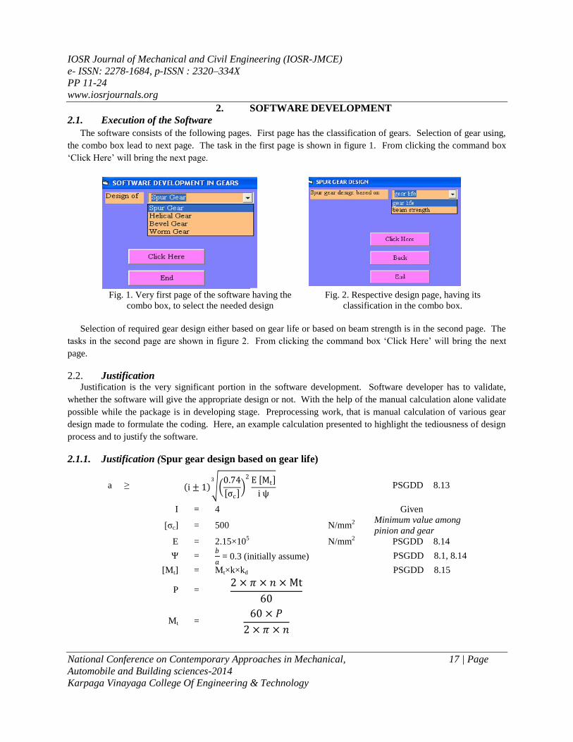
The software consists of the following pages. First page has the classification of gears. Selection of gear using,
the combo box lead to next page. The task in the first page is shown in figure 1. From clicking the command box
„Click Here‟ will bring the next page.
Fig. 1. Very first page of the software having the
combo box, to select the needed design
Fig. 2. Respective design page, having its
classification in the combo box.
Selection of required gear design either based on gear life or based on beam strength is in the second page. The
tasks in the second page are shown in figure 2. From clicking the command box „Click Here‟ will bring the next
page.
2.2. Justification Justification is the very significant portion in the software development. Software developer has to validate,
whether the software will give the appropriate design or not. With the help of the manual calculation alone validate
possible while the package is in developing stage. Preprocessing work, that is manual calculation of various gear
design made to formulate the coding. Here, an example calculation presented to highlight the tediousness of design
process and to justify the software.
2.1.1. Justification (Spur gear design based on gear life)
a ≥ i ± 1 0.74
σc
2 E Mt
i ψ
3
PSGDD 8.13
I = 4 Given
[σc] = 500 N/mm2
Minimum value among
pinion and gear
E = 2.15×10⁵ N/mm
2 PSGDD 8.14
Ψ = 𝑏
𝑎 = 0.3 (initially assume) PSGDD 8.1, 8.14
[Mt] = Mt×k×kd PSGDD 8.15
P = 2 × 𝜋 × 𝑛 × Mt
60
Mt = 60 × 𝑃
2 × 𝜋 × 𝑛

IOSR Journal of Mechanical and Civil Engineering (IOSR-JMCE)
e- ISSN: 2278-1684, p-ISSN : 2320–334X
PP 11-24
www.iosrjournals.org
National Conference on Contemporary Approaches in Mechanical, 18 | Page
Automobile and Building sciences-2014
Karpaga Vinayaga College Of Engineering & Technology
Design a pair of spur gear to transmit 20kW at pinion speed is 1400 rpm, transmission ratio is 4. Assume
suitable material and stresses [3-7].
Given
P = 20 kW = 20×103 W, n = 1400, rpm; i = 4
1. Material selection
Material [σb] [σc]
N/mm2
Pinion 15Ni2Cr1Mo15 320 950
Gear C45 140 500
From PSG Design data book: 1.40, 8.4 & 8.5
2. Minimum centre distance
a
≥ i ± 1 0.74
σc
2 E Mt
i ψ
3
PSGDD 8.13
I = 4 Given
[σc] = 500 N/mm2
Minimum value among
pinion and gear
E = 2.15×10⁵ N/mm
2 PSGDD 8.14
Ψ = 𝑏
𝑎 = 0.3 (initially assume) PSGDD 8.1, 8.14
[Mt] = Mt×k×kd PSGDD 8.15
P = 2 × 𝜋 × 𝑛 × Mt
60
Mt = 60 × 𝑃
2 × 𝜋 × 𝑛
= 60 × 20 × 103
2 × 𝜋 × 1400
= 136.418 N-m
K. Kd = 1.3 (initially assume) PSGDD 8.15
[Mt] = 136.418×1.3
= 60 × 20 × 103
2 × 𝜋 × 1400
= 136.418 N-m
K. Kd = 1.3 (initially assume) PSGDD 8.15
[Mt] = 136.418×1.3
= 177.343 N-m
= 177.343 × 10³ N-mm
a =
4
+ 1 0.74
σc
22.15 × 106 × 177.343 × 103
4 × 0.3
3
a = 205.669 ≈ 206 Mm

IOSR Journal of Mechanical and Civil Engineering (IOSR-JMCE)
e- ISSN: 2278-1684, p-ISSN : 2320–334X
PP 11-24
www.iosrjournals.org
National Conference on Contemporary Approaches in Mechanical, 19 | Page
Automobile and Building sciences-2014
Karpaga Vinayaga College Of Engineering & Technology
= 177.343 N-m
= 177.343 × 10³ N-mm
a =
4
+ 1 0.74
σc
2 2.15 × 106 × 177.343 × 103
4 × 0.3
3
a = 205.669 ≈ 206 Mm
3. Minimum module
m ≥ 1.26 Mt
y σb Ψm Z1
3
PSGDD 8.13A
[Mt] = 177.343 × 10³ N-mm
Y = 0.389 (assume Z1 = 20 and X = 0) PSGDD 8.18
[σb] = 140 N/mm2
Minimum value among
pinion and gear
Ψm = 𝑏
𝑚 = 10 (initially assume) PSGDD 8.14
Z1 = 20 (initially assume) PSGDD 8.18
m = 1.26 177.343 × 10³
0.389 × 140 × 10 × 20
3
Minimum centre distance value
rounded off from recommended series
available in design data
m = 3.194 ≈ 4 Mm PSGDD 8.2
4. Calculation of number of teeth
Z1 = 2𝑎
𝑚(𝑖 + 1) PSGDD 8.22
= 2 × 206
4 × (4 + 1)
= 20.6 ≈ 22 (Rounded off from table 18 in design data) PSGDD 8.18
Z2 = i Z1
= 4×22 = 88
5. Calculation of pitch circle diameter
d1 = mZ1 = 4×22 = 88 Mm PSGDD 8.22
d2 = mZ2 = 4×88 = 352 Mm PSGDD 8.22
6. Correction of center distance
𝑎 = 𝑑1+𝑑2
2=
88+352
2= 220 𝑚𝑚> 206 mm
Calculated center distance is greater than the early calculated one. Hence the design is safe.
IOSR Journal of Mechanical and Civil Engineering (IOSR-JMCE)
e- ISSN: 2278-1684, p-ISSN : 2320–334X
PP 11-24
www.iosrjournals.org
National Conference on Contemporary Approaches in Mechanical, 20 | Page
Automobile and Building sciences-2014
Karpaga Vinayaga College Of Engineering & Technology
7. Calculation of face width
Ψ = 𝑏
𝑎
Ψm = 𝑏
𝑚
0.3 = 𝑏
220
10 = 𝑏
4
b = 66 B = 40
Consider the larger among the above values. Therefore face width b = 66 mm
8. Revision of design torque
[Mt] = Mt×k×kd PSGDD 8.15
k - Load concentration factor for steel gears of quality IS 8 having HB > 350
(assume bearings close to gears and symmetrical)
Ψ𝑝 =𝑏
𝑑1=
66
88= 0.75
If Ψp = 0.6, k = 1.03
If Ψp = 0.8, k = 1.06, therefore k calculated based on interpolation
0.75 − 0.6
0.8 − 0.6=
𝑘 − 1.03
1.06 − 1.03
k = 1.0525
PSGDD 8.15
kd - Dynamic load factor (assumption IS 8 quality cylindrical gear)
𝑣 = 𝜋𝑑1𝑛1
60000=
𝜋 × 88 × 1400
60000= 6.451 𝑚/𝑠
If v = 3 m/s, kd = 1.3
If v = 8 m/s, kd = 1.6, therefore kd calculated based on interpolation 6.451 − 3
8 − 3=
𝑘𝑑 − 1.3
1.6 − 1.3
kd = 1.369
PSGDD
8.16
[Mt] = 136.418 × 1.0525 × 1.369
= 200.585 N-m
= 200.585 × 10³ N-mm
9. Checking of bending stress
σb = 𝑖+1
𝑎𝑚𝑏𝑦[𝑀𝑡] ≤ [σb] PSGDD 8.13A

IOSR Journal of Mechanical and Civil Engineering (IOSR-JMCE)
e- ISSN: 2278-1684, p-ISSN : 2320–334X
PP 11-24
www.iosrjournals.org
National Conference on Contemporary Approaches in Mechanical, 21 | Page
Automobile and Building sciences-2014
Karpaga Vinayaga College Of Engineering & Technology
I = 4
A = 220 Mm
M = 4 Mm
B = 66 Mm
Y = 0.402 (Z1 = 22 and X = 0) PSGDD 8.18
[Mt] = 196.563 × 10³ N-mm
σb =
(4 + 1)
220 × 4 × 66 × 0.402× 196.563
× 103
= 42.944 ≤ 140 N/mm2
Calculated bending stress is less than the design bending stress. Hence, Design is safe.
10. Checking for compressive stress
σc = 0.74(𝑖+1)
𝑎
(𝑖+1)
𝑖𝑏𝐸[𝑀𝑡] ≤ [σc] PSGDD 8.13
E = 2.15×10⁵ N/mm
2
B = 66 Mm
[Mt] = 196.563 × 10³ N-mm
σc = 0.74 ×(4 + 1)
220
(4 + 1)
4 × 66× 2 × 105 × 196.563 × 103
= 480.592 ≤ 500 N/mm2
Calculated compressive stress is less than the design compressive stress. Hence, Design is safe.
11. Checking for compressive stress
σc = 0.74(𝑖+1)
𝑎
(𝑖+1)
𝑖𝑏𝐸[𝑀𝑡] ≤ [σc] PSGDD 8.13
E = 2.15×10⁵ N/mm
2
B = 66 Mm
[Mt] = 196.563 × 10³ N-mm
σc = 0.74 ×(4 + 1)
220
(4 + 1)
4 × 66× 2 × 105 × 196.563 × 103
= 480.592 ≤ 500 N/mm2
Calculated compressive stress is less than the design compressive stress. Hence, Design is safe.
12. Other parameters
f0 =1 and c = 0.25 PSGDD 8.1
ha = f0m = 1×4 = 4 Mm PSGDD 8.22
hf = (f0+c) m = 1.25×4 = 5 Mm PSGDD 8.22
da1 = d1+2ha = 88+2×4 = 96 Mm PSGDD 8.24
da2 = d2+2ha = 352+2×4 = 360 Mm PSGDD 8.24
df1 = d1-2hf = 88-2×5 = 78 Mm PSGDD 8.24
df2 = d2-2hf = 352-2×5 = 342 Mm PSGDD 8.24

IOSR Journal of Mechanical and Civil Engineering (IOSR-JMCE)
e- ISSN: 2278-1684, p-ISSN : 2320–334X
PP 11-24
www.iosrjournals.org
National Conference on Contemporary Approaches in Mechanical, 22 | Page
Automobile and Building sciences-2014
Karpaga Vinayaga College Of Engineering & Technology
Table 1 –Specification
Sl. No. Description Pinion Gear
1 Material 15Ni2Cr1Mo15 C45
2 Number of teeth 22 88
3 Pitch circle diameter 88 mm 352 mm
4 Tip circle diameter 96 mm 360 mm
5 Root circle diameter 78 mm 342 mm
6 Centre distance 220 mm
7 Face width 66 mm
8 Torque 196.563 × 10³ N – mm
9 Module 4 mm
10 Addendum 4 mm
11 Dedendum 5 mm
12 Height factor 1 mm
13 Bottom clearance 0.25 mm
14 Tooth depth 9 mm
Earlier two tasks, brings the respective design input page. Here, sample page i.e., design of spur gear based on
gear life illustrating the inputs like power, speed ratio, material for pinion and gear, etc.
Fig. 3 Spur gear design based on gear life, calculation page

IOSR Journal of Mechanical and Civil Engineering (IOSR-JMCE)
e- ISSN: 2278-1684, p-ISSN : 2320–334X
PP 11-24
www.iosrjournals.org
National Conference on Contemporary Approaches in Mechanical, 23 | Page
Automobile and Building sciences-2014
Karpaga Vinayaga College Of Engineering & Technology
Fig. 4 Final specification page
Adopt all the primary inputs in the text box and then command box „Click Here‟ will lead to get the
calculated data‟s in the right side column in the same page which was consisting mean torque, design torque,
equivalent young‟s modulus, module, number of teeth, pitch circle diameter and etc as illustrated in figure 3. The
same page has the design status, whether calculated bending and surface stress is in safe zone of not so. If, the
design is not safe, iteration is possible form the module dimensions. By means of many ways that is by changing the
gear material or by changing the pinion material or increasing the centre distance or increasing module lead to safe
design. Here, one can change their input of preliminary calculated values accordingly they can make safest design.
After the verification of the calculated data‟s, the command box „Result‟ leads to the next page i.e., final
specification page. A database (Microsoft office access), recall the data‟s with respect to the input and adapt for the
further calculation.
The figure 4 has shown the final specification page for the spur gear. Design is an iterative process, aiming
at reaching the best possible result. If the first design is not satisfactory, further modifications are to be carried out
till the best performance is obtained. The software gives such a nice feasibility to the users.
Table 2-Justification of Results
Description Symbol Manual
Calculation Software Result Unit
Number of teeth on pinion z1 21 21
Number of teeth on gear z2 88 88
Pitch circle diameter of pinion d1 88 88 mm
Pitch circle diameter of gear d2 352 352 mm
Tip circle diameter of pinion da1 96 96 mm
Tip circle diameter of gear da2 360 360 mm
Root circle diameter of pinion df1 78 78 mm
Root circle diameter of gear df2 342 342 mm
Calculated bending stress σb 42.949 42.949 N/mm2
Calculated surface stress σc 480.592 480.592 N/mm2
Face width B 66 66 mm
Torque Mt 200.535 200.535 N-m
Center distance A 220 220 mm

IOSR Journal of Mechanical and Civil Engineering (IOSR-JMCE)
e- ISSN: 2278-1684, p-ISSN : 2320–334X
PP 11-24
www.iosrjournals.org
National Conference on Contemporary Approaches in Mechanical, 24 | Page
Automobile and Building sciences-2014
Karpaga Vinayaga College Of Engineering & Technology
Module M 4 4 mm
Addendum ha 4 4 mm
Dedendum hf 5 5 mm
Height factor fo 1 1 mm
Bottom clearance C 0.25 0.25 mm
Tooth depth H 9 9 mm
Comparing (table 2) the manual calculation with the software results shows good agreement among results. Similar
validation of each and every page i.e. helical, bevel and worm gear design based on gear life as well as beam
strength, carried out to give fullness to the package.
2.3. Features Within a short span one can do the design without manual error.
Even a semi skilled operator enough to do the design.
User can do the optimum design, by changing the numerical in the respective design calculation pages.
2.4. Future development At present the software includes the design of various gears. It is planned to include the other design such
as machine elements, transmission system and jigs and fixture, etc. Integration of modeling software can generate
graphical output. Further studies needed to incorporate those things.
3. CONCLUSION This study presents a new method of gear design and detailed with computer. Developed system provides the
user to perform repetitive and routine tasks involved in gear design, also provides a flexibility to optimize the design
process which will improve the productivity by means of reducing manufacturing cost. It was evident that the
developed system will successfully increase productivity by roughly twenty times over manual gear design at
reduced cost, provides significant saving time reduces its convolution.
REFERENCES [1] J. O. Nordiana, S. O. Ogbeide, N. N. Ehigiamuose and F. I. Anyasi, “Computer Aided Design of a Spur Gear” Journal of
Engineering and Applied Sciences 2 (12):1743-1747, 2007.
[2] M. Varatharajulu and R. Rajendran, “Software Development in Design”, CiiT International Journal of Software Engineering
and Technology 2011 Vol. 3 (8), 366 – 371.
[3] Bhandari. V. B, “Design of Machine Elements”, Tata McGraw-Hill Publishing Company Ltd., 1994
[4] Juvinall R. C., and Marshek K. M., “Fundamentals of Machine component Design”, John Wiley and Sons, Third Edition,
2002.
[5] Maitra G.M., and Prasad L.V., “Hand book of Mechanical Design, II Edition, Tata McGraw-Hill, 1985.
[6] Shigley J. E. and Mischke C. R., “Mechanical Engineering Design”, McGraw-Hill International Edition, 1989.
[7] Kurmi.R. S. “Machine Design”, S. Chand and Company Limited.
[8] Orthwein W, “Machine Component Design”, Jaico Publishing Co, 2003.
[9] Ugural A.C, “Mechanical Design – An Integral Approach, McGraw-Hill Book Co, 2004.
[10] Spotts M.F., Shoup T.E. “Design and Machine Elements” Pearson Education, 2004.
[11] Ibrahim Zeid, “CAD/CAM Theory and Practice”, Tata McGraw-Hill, 1998.
[12] Content development group, “Visual Basic 6.0 Programming”, Tata McGraw-Hill, 2009.