A small gas inlet system for orbital mass-spectrometer
34
- NASA Technical Paper 1170 A Small Gas Inlet System for Orbital Mass-Spectrometer Calibrations Alphonsa Smith and Richard E. Stell \ APRIL 1978 \ NASA https://ntrs.nasa.gov/search.jsp?R=19780013487 2019-01-05T16:46:48+00:00Z
Transcript of A small gas inlet system for orbital mass-spectrometer
-
NASA Technical Paper 1170
A Small Gas Inlet System for Orbital Mass-Spectrometer Calibrations
Alphonsa Smith and Richard E. Stell
\
APRIL 1978
\
NASA
https://ntrs.nasa.gov/search.jsp?R=19780013487 2019-01-05T16:46:48+00:00Z
TECH LIBRARY KAFB, NM
0134585
NASA Technical Paper 1170
A Small Gas Inlet System for Orbital Mass-Spectrometer Calibrations
Alphonsa Smith and Richard E. Langley Research Ceizter Hamptotz, Virginia
Naiional Aeronautics and Space Administration
Scientific and Technical Information Office
1978
Stell

SUMMARY
A gas i n l e t system is descr ibed f o r genera t ing p r e c i s e gas p re s su res t h a t are t o be used as c a l i b r a t i o n r e fe rences f o r t h e mass spec t rometers aboard t h e dua l a i r dens i ty (DAD) Explorer s a t e l l i t e s . This gas i n l e t system w a s developed as an i n - f l i g h t c a l i b r a t i o n technique i n which a known amount o f onboard gas is r e l e a s e d i n t h e s a t e l l i t e c a v i t y and is de tec t ed by t h e mass spectrometer . Although s e v e r a l f l i g h t mass-spectrometer experiments have been proposed, none make use o f t h e i n - f l i g h t c a l i b r a t i o n technique descr ibed i n t h i s r e p o r t . Laboratory measurements and c a l i b r a t i o n of t h e meter ing l e a k technique f o r t h e gas i n l e t systems are d iscussed . The systems t e s t e d have meter ing l eak rates between 2 and 4 lll/sec a t 298 K f o r argon-40, and they produce molecular f low up t o 100 t o r r , which is t h e h ighes t t es t p re s su re i n t h i s experiment. One set o f equat ions is presented t h a t can be used t o p r e d i c t t h e s a t e l l i t e c a l i b r a t i o n p res su res as a func t ion o f time during t h e metered gas flow. Another set o f equat ions is a l s o presented t o p r e d i c t t h e s a t e l l i t e p res su re during t h e t i m e t h e metered gas flow is terminated. These equat ions are u s e f u l f o r designing similar systems f o r f u t u r e a p p l i c a t i o n s and f o r extending d a t a comparisons beyond t h e l i m i t s t e s t e d i n t h i s program. Test data show t h a t metering l eak r a t e s a r e r ep roduc ib le wi th in 1 percent o f e s t a b l i s h e d means f o r helium-3, helium-4, and argon-40.
INTRODUCTION
When t h e purpose o f an i n v e s t i g a t i o n is t o measure t h e d e n s i t y , c o n s t i t u e n t s , and seasonal changes o f t he atmosphere by us ing s t a t i o n e d mass spectrometers i n o r b i t i n g satel l i tes , a method of i n - f l i g h t c a l i b r a t i o n is h igh ly desirable. The DAD Explorers were equipped with mass spec t rometers t o measure t h e number dens i ty o f exospher ic n e u t r a l p a r t i c l e c o n s t i t u e n t s over a 2-year pe r iod . A gas i n l e t system f o r t he i n - f l i g h t performance eva lua t ion and cal i b r a t i o n of t h e mass spec t rometers was developed f o r t h e DAD s a t e l l i t e s . The two s a t e l l i t e s , one a 0.762-m-diameter aluminum sphere and t h e o the r a 3.66-mdiameter aluminized Mylar1 i n f l a t a b l e ba l loon sphere , were t o be placed i n t o coplanar po la r o r b i t s a t e l e v a t i o n s o f 350 km t o 750 km and 750 km t o 1500 km, r e s p e c t i v e l y ( r e f . 1 ) . The s a t e l l i t e s were f u n c t i o n a l l y similar i n des ign , as shown i n f i g u r e 1 by t h e art ist 's concept o f t he s a t e l l i t e s i n o r b i t . They were fabricated with a large number of uniformly d i s t r i b u t e d , small-diameter p e r f o r a t i o n s t h a t c o n s t i t u t e about 1 percent of t h e i r s u r f a c e areas. The p e r f o r a t i o n s allowed free exchange o f molecules from t h e atmosphere t o wi th in t h e s a t e l l i t e s h e l l s and insured t h a t t he number d e n s i t y o f a tmospheric cons t i t u e n t s w i th in t h e s a t e l l i t e s h e l l s where t h e mass spec t rometer was loca ted would be the same r e g a r d l e s s o f s a t e l l i t e o r i e n t a t i o n . The gas i n l e t meter ing systems employed argon-40 and t h e helium-3 i so tope as c a l i b r a t i o n gases f o r t h e i n - f l i g h t c a l i b r a t i o n p rocesses . The gas i n l e t system des ign was similar t o t h e l abora to ry systems t h a t are d iscussed i n r e f e r e n c e s 2 , 3 , and 4 and t h a t have been used wi th cons ide rab le success f o r s e v e r a l yea r s .
IMylar: Registered trademark o f E. I. du Pont de Nemours & Co., Inc .
I
l l l l l I 1
The purpose o f t h i s r e p o r t is t o describe the onboard gas meter ing leak systems developed f o r DAD, t o d e s c r i b e b r i e f l y t h e c h a r a c t e r i s t i c o p e r a t i o n , and t o p re sen t some r e s u l t s observed i n t he l a b o r a t o r y . This r e p o r t is l i m i t e d t o l abora to ry r e s u l t s f o r the i n l e t system s i n c e they are the only r e s u l t s a v a i l a b l e . Launch o f t h e BAD Explorer experiment w a s unsuccessfu l because o f f a i l u r e o f t h e Scout rocke t .
Use of t r a d e names or names of manufacturers i n t h i s r e p o r t does no t cons t i t u t e an o f f i c i a l endorsement of such products or manufacturers , e i ther expressed or impl ied , by the Nat iona l Aeronaut ics and Space Adminis t ra t ion.
SYMBOLS
C conductance, l /sec
CC conductance f o r c a l i b r a t i o n gas, l / sec
CO conductance f o r r e fe rence gas, l /sec
MC molecular weight o f c a l i b r a t i o n gas, g/mol
MO molecular weight of r e fe rence gas, g/mol
n number o f c a l i b r a t i o n s
P p res su re , t o r r ( 1 t o r r = 133.3 Pa)
Pt=O p res su re a t time equa l z e r o , t o r r
P ( t > p re s su re as a func t ion of time, t o r r
P ( t )sc ,n p res su re i n s to rage c y l i n d e r as a func t ion of time f o r t h e n th c a l i b r a t i o n , t o r r
Q1 gas flow rate from s to rage c y l i n d e r i n t o s a t e l l i t e , t o r r - l / s e c
Q2 gas flow rate from atmosphere i n t o s a t e l l i t e , t o r r - l / s e c
Q3 gas flow rate from s a t e l l i t e t o atmosphere, t o r r - l / s e c
t time, sec
TC temperature of c a l i b r a t i o n gas, K
TO temperature o f r e fe rence gas, K
V volume, 1
T p la t eau time, sec
2

Subsc r ip t s :
is i n s i d e s a t e l l i t e
os o u t s i d e s a t e l l i t e
1 porous metal meter ing leak
S sa te l l i t e
sc s t o r a g e c y l i n d e r
t t rapped
IN-FLIGHT CALIBRATION SYSTEM
The major components o f t h e DAD i n - f l i g h t c a l i b r a t i o n system are the gas i n l e t system and t h e pe r fo ra t ed s a t e l l i t e s h e l l . These two components a c t t o e s t a b l i s h an accu ra t e t i m e h i s t o r y o f c a l i b r a t i o n gas p res su re wi th in the s p h e r i c a l volume enclosed by t h e s h e l l of t h e s a t e l l i t e . The known parameters of these components provide a l l t he information needed t o a c c u r a t e l y determine t h e c a l i b r a t i o n gas p re s su re a t any i n s t a n t during a c a l i b r a t i o n p rocess . The parameters are d i s c u s s e d and the gas p re s su re equat ions a r e developed i n d e t a i l i n t h e fol lowing s e c t i o n . One o f t h e important parameters needed was t h e time requi red f o r t h e p re s su re i n s i d e the sa te l l i t es t o reach equi l ibr ium. Pressure equi l ibr ium is maintained i n t h e s a t e l l i t e s when t h e flow o f gas from the i n l e t system is equal t o the flow o f gas e x i t i n g through the p e r f o r a t i o n s o f t he s a t e l l i t e s h e l l ; for f ree-molecular flow cond i t ions , the p res su re equat ion s i m p l i f i e s t o
T h i s p re s su re equ i l ib r ium occurs approximately 1.39 sec a f te r i n i t i a t i n g t h e c a l i b r a t i o n gas i n p u t f o r the 0.762-m-diameter s a t e l l i t e , and approximately 5.51 sec a f t e r i n i t i a t i n g the gas i n p u t f o r t h e 3.66-m-diameter s a t e l l i t e . Two gases were chosen f o r c a l i b r a t i o n purposes; argon-40 was used f o r t h e high mass c a l i b r a t i o n , and t h e helium-3 i so tope w a s used f o r t h e low mass c a l i b r a t i o n s o t h a t t he mass spectrum would not be confused w i t h a tmospheric helium-4. A command c o n t r o l s i g n a l from a ground s t a t i o n was t r ansmi t t ed t o t h e s a t e l l i t e t e l eme t ry t o a c t i v a t e the s e q u e n t i a l t i m i n g c i r c u i t s o f the gas c a l i b r a t i o n system t h a t were a s s o c i a t e d w i t h t he in s t rumen ta t ion e l e c t r o n i c s . When t h e in le t - sys tem latching so leno id va lve opens, gas flows from t h e in le t - sys tem s to rage c y l i n d e r (V = 5 c l ) , through the porous metal meter ing l e a k , i n t o the sa te l l i t e volume, and ou t through t h e s a t e l l i t e s k i n p e r f o r a t i o n s . The I-percent sur face-area p e r f o r a t i o n s of t he DAD s a t e l l i t e she l l are equ iva len t t o Cs = 1.75 kl/sec f o r the 0.762-m sa te l l i t e and 41.9 kl /sec f o r the 3.66-m sa te l l i t e . The s a t e l l i t e conductances g iven here apply f o r argon-40 a t 298 K.
3
I

Ill1 I I IIIIIII I I 1
THEORY AND D E S I G N PARAMETERS
To provide t h e pressure- t ime r e l a t i o n s h i p o f t he c a l i b r a t i o n gases i n t h e two sa te l l i t es , it was necessary t o de r ive equa t ions showing t h e i r f u n c t i o n a l dependence on t h e gas in le t - sys tem parameters . Consider t he schematic shown i n f i g u r e 2 f o r a c a l i b r a t i o n gas flowing from the in l e t - sys t em s t o r a g e c y l i n der, through a meter ing l eak o f conductance C 1 , i n t o t h e pe r fo ra t ed s a t e l l i t e s h e l l , and o u t i n t o the surrounding space. The s t o r a g e c y l i n d e r p re s su re a t any time t af ter the va lve is opened is descr ibed by t h e express ion
I n s i d e t h e sphere , t he p r e s s u r e is descr ibed by the equat ion of flow
Mul t ip ly ing through by VS-' d t and s u b s t i t u t i n g from equat ion ( 2 ) g i v e s t h e fo l lowing equat ion :
"S "S
Using the i n t e g r a t i o n f a c t o r as g iven by
exp (1 dt) = e x p k t)
t o so lve the d i f f e r e n t i 1 equat ion and i n t e r a t i n g equat ion (3) g i v e s
I"
where k is an a r b i t r a r y i n t e g r a t i o n cons t an t .
4
1
~ , . . . . . . . . . .

Solving the i n t e g r a l s o f equat ion (5 ) g ives
A t t = 0,
c1 Pt=O.sc
Therefore , t h e a r b i t r a r y i n t e g r a t i o n cons t an t is obta ined from t h e i n i t i a l cond i t i o n s as
When t h e i n t e g r a t i o n cons t an t is s u b s t i t u t e d i n t o equat ion (61 , t h e fol lowing equat ion is obta ined :
c1 P t = O , s c + P t = O , i s -
vs - cs c1 - Pos
CS Af t e r mu l t ip ly ing through by ex.(- v,t) and combining terms, equat ion (91,
which g i v e s t h e f u n c t i o n a l r e l a t i o n f o r p ( t ) i s , is obta ined:
5

When the va lve shown i n f i g u r e 2 is closed i n t h e c a l i b r a t i o n procedure, the cons t an t Vsc is rep laced by V t , which is the t rapped volume between t h e va lve and the porous metal meter ing leak. Each time t h e va lve is opened, t h e p r e s s u r e i n t h e s t o r a g e c y l i n d e r is expanded i n t o t he t rapped volume between the va lve and the porous metal meter ing leak such t h a t t h e p re s su re i n t h e s t o r a g e cy l inde r is reduced by a small amount g iven by t h e cons t an t 0.999. This cons tan t must be introduced t o account f o r t h e p re s su re r educ t ion i n the s t o r a g e c y l i n d e r which occurs when the expanding gas from t h e s t o r a g e c y l i n d e r f i l ls the void between t h e s t o r a g e c y l i n d e r and the porous metal meter ing leak. This would then y i e l d a g e n e r a l express ion t h a t can be used when the calibrat i o n i n t e r v a l s are the same ( t h a t is , when the va lve is open f o r the same increment of t ime).
It is necessary t o know p ( t ) a f t e r t he va lve had been opened f o r a spec i f i e d time so t h a t t h e p r e s s u r e i n t h e sa te l l i t e could reach a maximum and t h e va lve could then be c losed . After the p res su re i n the s a t e l l i t e has reached a maximum, the p res su re is descr ibed by equat ion (91 , w i t h Vsc rep laced by V t . I n t h i s mode o f o p e r a t i o n , pt=O,sc i n equat ion ( 9 ) must be i n t e r p r e t e d as be ing the p res su re i n the s to rage c y l i n d e r a t t h e i n s t a n t t h e va lve is c losed .
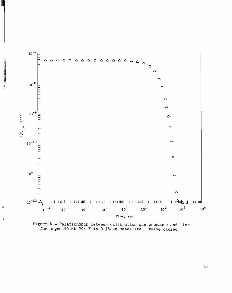
Typical pressure- t ime r e l a t i o n s h i p s f o r t he argon-40 c a l i b r a t i o n gas a t 298 K f o r the two sa t e l l i t e s are shown i n f i g u r e s 3 t o 6 . F igures 3 and 5 show the pressure- t ime curves f o r t he 0.762-111 and 3.66-111 s a t e l l i t e s , r e s p e c t i v e l y , when the valve is opened and remains open u n t i l t h e p re s su re i n s i d e the satell i t e is e q u i l i b r a t e d t o t h e p re s su re o u t s i d e . These curves show t h a t p ( t ) i s reaches a p la t eau and remains e s s e n t i a l l y cons t an t f o r s e v e r a l minutes. The programed open time f o r t h e in le t - sys tem va lves f o r an o r b i t c a l i b r a t i o n sequence was 16 sec, and t h e p l a t eau times were 1.39 and 5.51 sec f o r t h e 0.762-111 and 3 . 6 6 4 s a t e l l i t e s , r e s p e c t i v e l y . Thus, there is ample time f o r calibrating the mass spec t rometers i n s i d e the s a t e l l i t e s . C a l i b r a t i o n s can be repea ted a t t h e p r e s s u r e p l a t e a u when t h e va lve is l e f t open long enough f o r P ( t ) i s t o reach a maximum. The curves shown i n f i g u r e s 3 and 5 were p l o t t e d i n order t o get an idea of how long after it reaches a maximum.
p ( t ) i s remains approximately cons t an t
It appears t h a t p ( t ) i s remains e s s e n t i a l l y cons t an t f o r approximately 1000 sec, which means t h a t there is p l e n t y o f t i m e for repea ted c a l i b r a t i o n sequences. The p r e f e r r e d program ope ra t ion f o r repea ted c a l i b r a t i o n s i s t o open the va lve s e p a r a t i n g t h e s t o r a g e c y l i n d e r from the sphere and a l low
6

P ( t ) i s t o reach a maximum, w i t h t h e va lve open only long enough t o make a c a l i b r a t i o n (approximately 16 sec). After t h e va lve is c losed , there is a d d i t i o n a l c a l i b r a t i o n time (as shown i n f i g s . 4 and 6 ) so t h a t P ( t ) i s can be monitored as it decreases from a maximum t o a minimum. From f i g u r e s 3 and 5 , i t can be seen t h a t p ( t ) i s reaches a maximum a t approximately 1.39 and 5.51 sec f o r t h e 0.762-m and 3.66-m s a t e l l i t e s , r e s p e c t i v e l y . The time requi red f o r the p res su re i n each sa t e l l i t e t o reach a maximum is a cons t an t and is a func t ion o f t he volumes and conductances involved f o r each sa t e l l i t e . T h i s p l a t eau t i m e 'c is obtained by d i f f e r e n t i a t i n g p ( t ) i s i n equat ion ( 9 ) w i t h r e s p e c t t o time and s e t t i n g i t equal t o ze ro . When t h i s is done, t he p l a t eau time is g iven by the fol lowing express ion:
S u b s t i t u t i n g f o r t he system parameters from tab le I g i v e s the p l a t e a u times, as shown i n f i g u r e s 3 and 5.
There are e s s e n t i a l l y two programed modes of ope ra t ion , and they are determined by t h e open or c losed p o s i t i o n o f t h e va lve s e p a r a t i n g t h e s t o r a g e cy l inde r from the s a t e l l i t e . The cond i t ion f o r the va lve i n t h e open p o s i t i o n has been descr ibed . It i s u s e f u l t o cons ider the cond i t ion when t h e va lve has been opened long enough f o r t h e p re s su re i n s i d e the s a t e l l i t e s h e l l t o reach t h e p l a t eau l e v e l and is then c losed . A s p rev ious ly mentioned, t h e p re s su re i n s i d e the sa te l l i t es is then given by equat ion ( 9 1 , w i t h Vsc replaced by V t . Therefore , when t h e va lve is c losed , the equat ion express ing t h e pressure i n t h e s a t e l l i t e becomes
From t h e data g iven i n table I, C 1 / V t is equal t o 0.02 sec-l and Cs/Vs is equal t o 7.563 and 1.635 sec-1 f o r t h e 0.762-m and 3.66-m s a t e l l i t e s ,
C 1 r e s p e c t i v e l y . The exponen t i a l f a c t o r exp(- t) has the largest in f luence
o f a l l t h e exponent ia l terms on p ( t ) i s as t i m e is inc reased . Pressure as a func t ion of time i n s i d e the s a t e l l i t e w i l l reach a minimum pres su re o u t s i d e the
7

- - -
exP(- yC1 t) C1
sa te l l i t e when the term - pt-O,sc is small ( 5 x t o r r ) w i t h V S cs c1
vs V t
r e s p e c t t o pos. This occurs a t approximately 813 sec f o r t h e 0.762-m s a t e l l i t e and a t 770 sec f o r the 3.66-111 sa te l l i t e . I n o rde r t o i l l u s t r a t e t h i s computat i o n , t h e p r e s s u r e o u t s i d e the sa te l l i t e i n f i g u r e s 4 and 6 was taken t o be 10-12 t o r r . Since the p res su re o u t s i d e the sa te l l i t e e n t e r s i n these pressure-time curves as a boundary cond i t ion , i t would be necessary t o r econs ide r these cond i t ions f o r experiments i n which a p res su re d i f f e r e n t than t o r r would be encountered. As long as t h e p re s su re o u t s i d e the s a t e l l i t e is much less than the maximum ( p l a t e a u ) p re s su re expected i n t h e s a t e l l i t e s , t h e p re s su re e q u i l i b r a t i o n times and p res su re p l a t eau would no t change f o r t h e case when p ( t ) i s is inc reas ing from minimum t o maximum. However, when P ( t ) i s is decreas ing from a p l a t e a u l e v e l t o a minimum pos, t he e q u i l i b r a t i o n time and minimum pres su re expected i n s i d e the s a t e l l i t e s are s t r o n g l y dependent on pos.
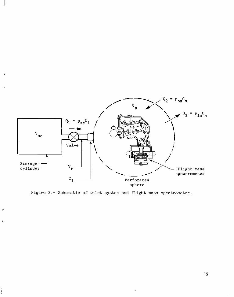
GAS INLET SYSTEM
I n f i g u r e 7 , the fou r major components of t h e DAD Explorer s a t e l l i t e gas i n l e t system are shown. They are the gas s t o r a g e c y l i n d e r , t he so lenoid va lve , t he porous metal meter ing l e a k , and t h e p re s su re t r ansduce r . The func t ion of the first three components i s t o s t o r e and t o d e l i v e r , upon command, e i ther o f the c a l i b r a t i o n gases (helium-3 or argon-40) a t a rate t h a t can be a c c u r a t e l y p red ic t ed . The f o u r t h component was used as a p a r t o f t h e s p a c e c r a f t monitori n g system only .
The s to rage c y l i n d e r p re s su re f o r t h e n th programed c a l i b r a t i o n p ( t l S c , n was used t o e s t a b l i s h gas flow i n t o the s a t e l l i t e s h e l l and is a c c u r a t e l y given by the express ion
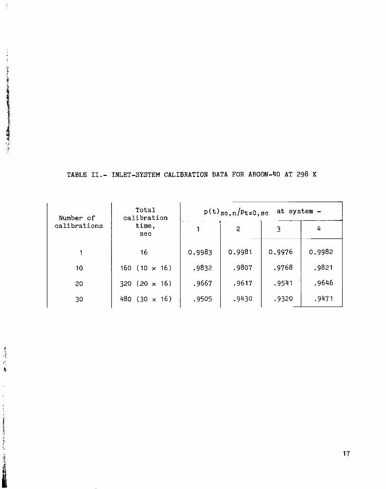
I n equat ion (121, t he cons t an t 0.999 is in t roduced t o account f o r a p res su re r educ t ion i n the s to rage c y l i n d e r t h a t was caused by t h e c a l i b r a t i o n gas expanding i n t o t h e t rapped volume (0 .5 m l ) between the va lve and the porous metal metering leak. Then, by knowing t h e i n i t i a l p re s su re i n t h e s t o r a g e c y l i n d e r pt=O,sc, the volume o f t h e s t o r a g e c y l i n d e r Vsc, t h e porous metal metering leak conductance C 1 , the time t tha t t h e flow is s u s t a i n e d , and the number o f c a l i b r a t i o n s n , t he p res su re i n t h e s t o r a g e c y l i n d e r p( t>, , can be reso lved f o r any p a r t i c u l a r i n s t a n t . I n o rde r t o t es t and eva lua te the system performance exper imenta l ly and t o check the p r e c i s i o n of equat ion (121, s e v e r a l i n l e t systems were assembled. The data i n t a b l e I1 show the r e s u l t s o f s e v e r a l c a l i b r a t i o n s f o r four i n l e t systems. I n t he DAD experiment, it was expected t h a t approximately 24 i n - o r b i t c a l i b r a t i o n s would be made during t h e
8

mission d u r a t i o n , and each c a l i b r a t i o n would las t f o r 16 sec. The data i n table I1 show t h a t a s u f f i c i e n t supply o f c a l i b r a t i o n gas from the i n l e t system would be a v a i l a b l e . After 30 c a l i b r a t i o n s , t h e p re s su re i n the s to rage c y l i n d e r s w a s greater than 90 percent o f t he o r i g i n a l va lue .
For the gas s t o r a g e c y l i n d e r , a 5-cl c y l i n d e r made o f AISI type 304 s t a i n less s teel was selected. It cons i s t ed o f two s e c t i o n s machined from s o l i d material and welded by an e l e c t r o n beam a t the equator . After welding, each c y l i n d e r w a s vacuum f i r ed a t 1123 K ( j u s t below the annea l ing temperature) t o remove contaminants and t o open any voids i n the material t h a t would l a t e r cause leak problems.
An e l e c t r i c a l l y operated double l a t c h i n g so lenoid va lve was selected because o f its low power consumption and extremely low leak rate. The va lve operated from either an open or c losed t e s t p o s i t i o n tha t r e q u i r e s an 8 t o 16 V dc pu l se and draws a peak c u r r e n t of about 1 A a t 8 V. Typica l ly , t he time dura t ion o f t h e vo l t age pu l se requi red t o ope ra t e the va lve was approximately 12 msec. The power requirements t o o p e r a t e the va lve were wi th in s p e c i f i c a t i o n s because t h e s a t e l l i t e ins t rumenta t ion power supply system perm i t t e d normal power supply f l u c t u a t i o n s o f 11 t o 15 V. The va lve leak rate was less than atm-cm3/sec as determined by a l abora to ry helium leak d e t e c t o r .
The p r e c i s i o n porous metal metering leak shown i n f i g u r e 8 had a nominal conductance C1 between 2 and 4 p l / s e c f o r argon-40 a t 298 K . The meter ing leaks were i n s t a l l e d a t t h e gas e x i t s i d e o f the va lve . The metering leak was made o f porous s t a i n l e s s s teel and was encapsula ted i n a small c y l i n d e r (0.64 x 0.64 c m ) formed from AISI type 304 s t a i n l e s s s teel ; t h e cy l inde r w a s p ressed i n t o an undersized aluminum adap te r (0.637 cm), as shown i n f i g u r e 8. The adap te r was fas t ened t o the va lve body w i t h e ight 1/2-56 machine screws t h a t use h e l i - c o i l l ock ing devices . A s i lve r - coa ted clamshell seal was used t o make the s e a l i n g s u r f a c e between the adapter and t h e va lve body.
The p re s su re t r ansduce r was attached t o t h e gas i n l e t systems t o monitor t h e s t o r a g e c y l i n d e r p re s su re i n f l i g h t . However, the t ransducer was a l s o used t o detect p o s s i b l e system malfunct ions such as i n c o r r e c t or i nope ra t ive va lve func t ions o r leaks. The t ransducer accuracy was not good enough f o r precise de termina t ion o f t h e s to rage c y l i n d e r p re s su re because each c a l i b r a t i o n sequence reduced the s t o r a g e c y l i n d e r p re s su re by only 1 p a r t i n 1000, and the t r a n s ducer accuracy was about 2 p a r t s i n 100.
The s t o r a g e c y l i n d e r , t he p re s su re t r ansduce r , and the l a t c h i n g so lenoid va lve were welded t o g e t h e r u s ing s t a i n l e s s s tee l tub ing t h a t had an o u t s i d e diameter o f 0.32 c m . The completed assembly was then tested f o r o v e r a l l leak rates o f less than atm-cd/sec.
After the leak t e s t i n g was completed, t h e 330-g i n l e t system was attached t o t he l abora to ry test system shown i n f i g u r e 9 without its porous metal meteri n g leak i n s t a l l e d . The system p res su re w a s then reduced t o 75 x 10-9 t o r r , and the temperature o f the i n l e t system wi th in the cont ro l led- tempera ture environmental chamber w a s raised t o 343 K. The in le t - sys tem outgass ing prod u c t s , p r i n c i p a l l y water, were examined w i t h a quadrupole mass-spectrometer
9

r e s i d u a l gas ana lyze r . Higher baking tempera tures could no t be used because t h e p re s su re t r ansduce r and t h e rare Ear th magnetic c o r e o f t h e so l eno id va lve were h igh ly s u s c e p t i b l e t o d e t e r i o r a t i o n .
After t h e outgass ing p res su re reduced t o w i t h i n 5 pe rcen t o f i ts former p re s su re l e v e l , va lves 5 and 1 were c losed . Gas from t h e c a l i b r a t i o n gas supply w a s used t o purge t h e i n l e t system through va lves 2 and 3. A t t h i s p o i n t , t h e quadrupole mass-spec t rometer r e s i d u a l gas ana lyze r showed only traces o f carbon monoxide, water, hydrogen, and methane. The i n l e t system was ,
then cooled t o room temperature and charged t o t h e a p p r o p r i a t e p re s su re by us ing 20-ppm impuri ty argon-40 o r helium-3 i so tope as r equ i r ed . Nominal va lues of charging p res su re were 7.50 t o r r fo r the 0.762-111 sa te l l i t e system and 75.02 t o r r f o r t h e 3.66-111 sa t e l l i t e system.
The porous metal metering l e a k s i n t h e i r a d a p t e r s were then i n s t a l l e d on each gas i n l e t system, and a f i n a l i n s p e c t i o n o f s t o r a g e c y l i n d e r gas p u r i t y was per formed.
LABORATORY APPARATUS
Figure 10 is a block diagram of t h e l a b o r a t o r y system used t o c a l i b r a t e t h e porous metal meter ing l e a k s , and f i g u r e 1 1 is a photograph of t h e laborat o r y t es t hardware. The tes t system c o n s i s t s o f a c a l i b r a t i o n gas supply , a manifold with an arrangement o f va lves a l lowing f o r i s o l a t i o n of each compon e n t , a quadrupole mass-spectrometer r e s i d u a l gas a n a l y z e r , a capac i tance manometer, a cont ro l led- tempera ture environmental chamber, and a gas s t o r a g e c y l i n d e r similar t o the f l i g h t - t y p e in le t - sys tem gas s t o r a g e c y l i n d e r . Typica l1 , t h e p re s su re i n t h e manifold could be reduced t o t h e range o f 75 x IO- 5 t o r r by us ing a combination o f mechanical, o i l - d i f f u s i o n , and cryogen ic pumping.
C a l i b r a t i o n gas supply: Research grade argon-40 and helium-4 gases with an impuri ty l e v e l of less than 20 ppm f o r c a l i b r a t i o n s .
Main manifold: S t a i n l e s s s t ee l with an i n s i d e diameter o f 4 .45 c m and a l e n g t h o f 35.6 cm.
Residual gas ana lyzer : Laboratory quadrupole mass spectrometer with a mass range o f 1 t o 500 atomic mass u n i t s and a minimum d e t e c t a b l e p a r t i a l p res s u r e equal t o IOm6 o f t he t o t a l p re s su re .
Capacitance manometer: Capacitance p r e s s u r e senso r w i t h a p r e s t r e s s e d diaphragm. T o t a l range is from 0.01 t o r r t o 997.6 t o r r .
Control led- temperature environmental chamber: Range 200 t o 588 K , c h i l l e d wi th C02, heated wi th e lec t r ica l elements . Temperature s t a b i l i t y dur ing tes ts is k0.56 K .
Pumping system: Inc ludes 10-cm o i l d i f f u s i o n pump with a mechanical backing pump, l i q u i d n i t rogen co ld t r a p , and 15-cm gate va lve . Approximate pumping speed is 500 l /sec.
10

Valves: Valves 1 and 5 i n f i g u r e s 9 and 10 are r igh t - ang le u l t r a h i g h vacuum type with a r a t e d conductance of 32 l /sec i n t h e f u l l y opened p o s i t i o n . Valve 2 is a low-conductance meter ing type used f o r r e g u l a t i n g c a l i b r a t i o n gas flow rates i n t o t h e manifold and a s s o c i a t e d volume. Valve 6 is a small la tch ing-so lenoid type similar t o t h e type used i n t h e f l i g h t systems. Valves 3 and 4 are s tandard labora tory- type tes t va lves .
SYSTEM TESTING AND RESULTS
Metering Leak C a l i b r a t i o n
One o f t h e most c r i t i ca l parameters of the c a l i b r a t i o n gas i n l e t system is t h e conductance o f t h e porous metal meter ing l eak . The conductance of each l eak was a c c u r a t e l y measured before i t was i n s t a l l e d i n t o a gas i n l e t system.
C a l i b r a t i o n s of t h e f l i g h t gas in le t - sys tem meter ing l e a k s were performed with the l abora to ry appa ra tus shown i n f i g u r e 1 1 . A f l i g h t gas i n l e t system t h a t was modified by having t h e p re s su re t ransducer rep laced with a s t a i n l e s s s t ee l tubing connect ion t o t h e s e n s i t i v e capac i tance manometer was loca ted wi th in t h e cont ro l led- tempera ture environmental chamber. Each l eak t o be ca l i bra ted was i n s t a l l e d on t h e in le t - sys tem va lve adap te r and sealed t o t h e vacuum manifold with a Teflon2 gaske t .
During l a b o r a t o r y system tes ts and c a l i b r a t i o n , va lves 2 , 3 , and 5 remained closed u n t i l t h e system p r e s s u r e w a s reduced t o 75 x t o r r . The temperat u r e i n t h e cont ro l led- tempera ture environmental chamber was increased t o 343 K and was he ld t h e r e u n t i l t h e temporary i n c r e a s e i n p re s su re due t o outgass ing from hea t ing w a s reduced t o less than 75 x 10-9 t o r r and u n t i l t h e r e s i d u a l gas ana lyzer showed trace l e v e l s of t h e c o n s t i t u e n t s hydrogen, methane, water, and carbon monoxide. Typ ica l ly , t h i s requi red 8 h r . The cont ro l led- tempera ture environmental chamber was then reduced t o room temperature , and t h e t e s t system was monitored f o r s e v e r a l hours by us ing the s e n s i t i v e capac i tance manometer and t h e r e s i d u a l gas ana lyze r t o check f o r l e a k s o r f u r t h e r ou tgass ing .
After the system was determined t o be free o f any contaminants , a small sample of t h e c a l i b r a t i o n gas (helium-3 o r argon-40) was examined with t h e r e s i d u a l gas ana lyzer f o r p u r i t y .
The porous metal meter ing l eak c a l i b r a t i o n s were performed by e s t a b l i s h i n g the appropr i a t e p re s su re l e v e l i n t h e t e s t system manifold f o r t h e c a l i b r a t i o n gas being used when t h e manifold pumping system va lve w a s o f f . The s e n s i t i v e capac i tance manometer was used t o determine t h e manifold p re s su re l e v e l , and t h e cont ro l led- tempera ture environmental chamber w a s used t o set t h e meter ing l e a k temperature t o a s p e c i f i e d t y p i c a l sa te l l i t e cond i t ion . The meter ing l eak under c a l i b r a t i o n , t h e test s t o r a g e volume, and t h e s e n s i t i v e capac i tance manometer were then s h u t o f f , and t h e t es t manifold evacuated by t h e pumping system. After wa i t ing 15 min (minimum t i m e ) f o r t h e p re s su re and temperature t o s t a b i l i z e , l eak c a l i b r a t i o n s were i n i t i a t e d . The i n i t i a l p re s su re and t h e
2Teflon: Regis te red trademark o f E. I. du Pont de Nemours & Co., Inc .
11

immediate p re s su re change were recorded, and va lve 6 o f f i g u r e 10 was opened t o permit c a l c u l a t i o n of t h e t rapped volume between the va lve seat and t h e porous metal metering leak being c a l i b r a t e d . The p res su re decrease as a funct i o n o f time dur ing the gas flow decay was recorded u n t i l t h e p re s su re w a s approximately ha l f its i n i t i a l va lue . These d a t a were then used t o compute t h e conductance o f t he porous metal meter ing l eak from the r e l a t i o n
c 1 = - -vsc I n
P(t)SC (13)
t P t = O , sc
Thi procedure was repea ted f o r s ev ra l c a l i b r a t i o n s by us ing h lium-4 as the c a l i b r a t i o n gas a t tempera tures of 261 K , 262 K , 308 K , and 309 K , which was the range expected i n t h e DAD Explorer s a t e l l i t e s i n o r b i t . A t l eas t one or more c a l i b r a t i o n s w i t h e i ther argon-40 o r helium-3 was then performed. Resu l t s of the computed conductances ( i n t h e range o f l / sec) f o r these test da t a f o r fou r f l i g h t systems are presented i n f i g u r e s 12 and 13. Each d a t a p o i n t is normalized t o 298 K f o r argon-40 by us ing t h e r e l a t i o n s h i p
IT,M,
The data obta ined i n d i c a t e a r e l a t i v e s tandard d e v i a t i o n o f less than 0.5 percen t from t h e mean.
Volume Measurements
Three volumes are c r i t i c a l f o r e s t a b l i s h i n g t h e c a l i b r a t i o n p res su re expected i n t h e s a t e l l i t e s h e l l s where t h e mass spec t rometers are s i t u a t e d . Two o f these volumes are loca ted wi th in the i n l e t system i t se l f . They are t h e small t rapped volume between the va lve seat and the porous meter ing leak, and t h e gas s t o r a g e c y l i n d e r volume, which inc ludes a l l the in t e rconnec t ing tub ing , t h e t r ansduce r , and t h e va lve c a v i t i e s . The t h i r d is t h e e f f e c t i v e volume of t h e sa te l l i t e i t s e l f , which a l s o affects t h e t r a n s i e n t characterist ics o f t h e sa te l l i t e c a l i b r a t i o n p r e s s u r e .
Measurements o f the l a b o r a t o r y test in le t - sys tem volume were made wi th a p r e c i s i o n p is ton-cyl inder vo lumetr ic micrometer t h a t was capable o f measuring displacements w i th in 700 pm. It was determined from measurements o f t h e p i s t o n and c y l i n d e r d iameters t h a t e r r o r s i n the volume measurements were approximately 220 pl.
The p r e c i s i o n p i s ton -cy l inde r vo lumetr ic micrometer was a t t ached t o t he in le t - sys tem test manifold a t va lve 2 ( f ig . 10). Th i s device was then used t o compress the gas a t atmospheric p r e s s u r e i n t h e test manifold, and t h e t o t a l volume was c a l c u l a t e d accord ing t o Boyle 's l a w from the measured p res su re and
12

volume changes. The volume o f t h e t e s t manifold was determined t o be 0.6004 1, which was wi th in 0.33 pe rcen t o f t h e mean o f 12 measurements. The in le t - sys tem s t o r a g e volume was determined by expanding the c a l i b r a t i o n gas from its volume i n t o t h e t es t manifold volume. These measurements y i e lded a mean va lue o f 0.0693 1, wi th in 0.14 pe rcen t , f o r t he in le t - sys tem volume.
Similar techniques were used t o determine t h e volume of t h e main manifold s e c t i o n i n f i g u r e 9 , i nc lud ing the s e n s i t i v e capac i tance manometer appendage. The volume of t h e main manifold s e c t i o n w a s determined t o be 0.5491 1, wi th in 0.02 pe rcen t .
The f l i g h t in le t - sys tem s t o r a g e volume measurements were determined by expanding gas i n t o t h e main manifold ( V = 0.5491 1). F l i g h t i n l e t system volumes obta ined wi th t h i s technique averaged 5.11 c l , w i th in 0.39 pe rcen t . E r r o r s accumulated from t h e volume measurements were determined t o be wi th in 0.4 perc e n t . Therefore , t h e volume of t h e f l i g h t c a l i b r a t i o n gas s t o r a g e c y l i n d e r is 5.11 k 0.04 c l .
An eva lua t ion o f measurement e r r o r s ( re f . 5) y i e lded a cumulat ive r e l a t i v e u n c e r t a i n t y o f less than 1 percent i n the volume, p r e s s u r e , and time parameters f o r t h e 0.762-m sa te l l i t e and less than 0 .5 percent f o r t h e 3.66-m s a t e l l i t e .
FLIGHT QUALIFICATION AND ACCEPTANCE TESTS
A pro to type gas i n l e t system was sub jec t ed t o t h e environmental s p e c i f i c a t i o n f o r t h e Scout Vehicle launch and t o the expected environment f o r t h e DAD Explorer s a t e l l i t e s i n o r b i t and performance tes ts . The gas i n l e t system w a s cycled through more than 200 c a l i b r a t i o n sequences with no d e t e r i o r a t i o n . A l l ’ f o u r f l i g h t u n i t s and the two backup u n i t s were o p e r a t i o n a l and unaf fec ted dur ing and after the s a t e l l i t e program f l i g h t acceptance tes ts .
LONG-TERM STORAGE RESULTS
Two i n l e t systems des igna ted as backup u n i t s were evacuated t o 7.5 x t o r r , s t o r e d f o r 370 days, and them a t t ached t o t h e l abora to ry test system o f f i g u r e 10. The p res su re P i o f t h e s t o r a g e systems was then determined from the expres s ion
P i V i (15)
where P i and V i are t h e i n i t i a l p re s su re and volume o f t h e i n l e t system, Pf is the f i n a l p re s su re o f t h e i n l e t manifold system, and Vm is the volume of t h e manifold system. The i n i t i a l p re s su re o f one u n i t had increased t o 0.59 t o r r , and the r e s i d u a l gas ana lyzer mass spectrometer showed t h e gas t o be H20. The i n i t i a l p re s su re o f t h e o the r u n i t had increased t o 8.28 t o r r , and t h e r e s i d u a l gas ana lyze r showed t h e gas t o be an undetermined subs tance , n e i t h e r a i r nor water. It was presumed t h a t t h e l a t te r system had not been p rope r ly c leaned . Fabr i ca t ion r eco rds showed t h a t n e i t h e r o f these i n l e t
13

system s t o r a g e c y l i n d e r s had been vacuum f i r e d du r ing cons t ruc t ion assembly; t h i s suggested t h a t test contaminants i n t h e system evolved dur ing t h e s t o r a g e time. This contaminat ion could have been e l imina ted i f t h e u n i t s had been vacuum f i r e d before f i n a l assembly.
CONCLUSIONS
The measurements and tes ts o f t h e gas i n l e t systems developed f o r t h e DAD Explorer sa te l l i tes l e d t o the fol lowing conclus ions :
1 . P r e c i s i o n gas i n l e t systems s u i t a b l e for use i n c a l i b r a t e d p r e s s u r e dev ices on sa te l l i t es have been developed and are p r a c t i c a l .
2. The DAD Explorer p r e c i s i o n gas i n l e t systems can produce about 30 16-sec t imed c a l i b r a t i o n sequences before t h e s t o r e d c a l i b r a t i o n gas p res su re has been reduced t o 90 percent .
3. C a l i b r a t i o n gas flow rates can be produced w i t h I -percent accuracy and r e p e a t a b i l i t y .
4 . Porous metal metering l e a k s having conductances i n t h e range o f IOe6 l / sec were developed and shown t o be practical f o r repea ted c y c l i n g and long-term use i n space f l i g h t cond i t ions .
5. S ince t h e p re s su re o u t s i d e t h e sa te l l i t es (pas> is not p r e c i s e l y known, a complete e r r o r a n a l y s i s cannot be g iven . However, c o l l e c t i v e l y t h e data i n d i c a t e t h a t a f r a c t i o n a l e r r o r o f about 8 pe rcen t can be quoted.
Langley Research Center Nat iona l Aeronaut ics and Space Adminis t ra t ion Hampton, VA 23665 March 8 , 1978
14

REFERENCES
1. Keating, Gerald M . ; and P r i o r , Edwin J . : The A i r Density Explorer S a t e l l i t e Program. NASA Paper presented a t t he 10th I n t e r n a t i o n a l Symposium on Space Technology and Science (Tokyo), Sept . 3-8, 1973.
2. Owens, Charles L . : I o n i z a t i o n Gauge Ca l ib ra t ion System Using a Porous P lug and Orifice. J . Vac. Sci. Technol. , v o l . 2 , no. 3, May/June 1965, pp. 104-108.
3. Out law, R . A . ; and S t e l l , R . E . : An I n S i t u Metal-Gas, Secondary-Standard Assembly f o r Ultrahigh-Vacuum Ins t rumenta t ion . J. Vac. S c i . Technol. , v o l . 8, no. 4 , July/Aug. 1971, pp. 608-610.
4. Hayward, W. H . ; and Jepsen, R . L . : A Simple High Vacuum Gauge C a l i b r a t i o n System. 1962 Transac t ions of t h e Ninth Nat iona l Vacuum Symposium o f t h e American Vacuum Soc ie ty , George H. Bancrof t , ed. , Macmillan Co., c.1962, pp. 459-462.
5. Granv i l l e , W i l l i a m Anthony; Smith, Percey F . ; and Longley, W i l l i a m Raymond: Elements o f t h e D i f f e r e n t i a l and I n t e g r a l Calculus . Rev. e d . , Ginn and Co., 1941, pp. 136-139.
15

TABLE I.- DESIGN CRITERIA DATA COMPUTED FOR ARGON-40 AT 298 K
C1. pl / sec . . . . . . . . . . . . . . . . . . . . . . C,. kl /sec . . . . . . . . . . . . . . . . . . . . . . V.. hl . . . . . . . . . . . . . . . . . . . . . . . . vsc. . . . . . . . . . . . . . . . . . . . . . . . . . V t . m l . . . . . . . . . . . . . . . . . . . . . . . . c1/Vs.. msec-1 . . . . . . . . . . . . . . . . . . . . c1/Vs. nsec-1 . . . . . . . . . . . . . . . . . . . . C 1 / V t . sec-1 . . . . . . . . . . . . . . . . . . . . . c./v.. sec-1 . . . . . . . . . . . . . . . . . . . . . ............. . . . . . . . . . . . . . . . . . . .
16
0.762-m 3.66-m s a t e l l i t e sa te l l i t e
10 10
1.75 41.9
2.31 256
5 5
0.5 0.5
0.2 0.2
43.3 0.39
0.02 0.02
7.563 1.635
10 100
T A B L E 11.- I N L E T - S Y S T E M C A L I B R A T I O N DATA FOR ARGON-40 A T 298 K
Tota l N u m b e r of c a l i b r a t i o n .. ~.
C a l i b r a t i o n s t i m e , 1 sec
1 16 0.9983
10 160 ( I O x 16) .9832
20 320 (20 x 16) .9667
30 480 (30 x 1 6 ) .9505
0.9981 0.9976
.9807 .9768 .982 1
.9617 .9541 .9646
.9430 .9320 .947 1

/-- os s
// vS x2=p-
\/IQ3 \ I
I \ /
\ \
//1Flight mass
i- spectrometer Perforated
sphere
Figure 2.- Schematic of inlet system and flight mass spectrometer.
19

a a a a a D a a a a a a a a
a
a
a
a
a
a
a
a
a
a
10-4 10-3 10-2 10-1 100 10' lo2
T i m e , sec
\ a a a a n
D
a
a
a
a
a
Luul 9
I
Figure 3.- Re la t ionsh ip between c a l i b r a t i o n gas p r e s s u r e and time for argon-40 a t 298 K i n 0.762-m s a t e l l i t e . Valve open.
20
. .
10-4 10-1 100 lo1 10
Time, sec
Figure 4.- Re la t ionsh ip between c a l i b r a t i o n gas p r e s s u r e and t i m e for argon-40 a t 298 K i n 0.762-111 sa te l l i t e . Valve c losed .
21

";IFa
n
D
n
n
n
n
n
D
n
n
D
F-. _I
n n D n D
n n
D
D
D
D
D
D
D
T i m e , sec
Figure 5.- Re la t ionsh ip between c a l i b r a t i o n gas p r e s s u r e and time fo r argon-40 a t 298 K i n 3.66-m sa t e l l i t e . Valve open.
22

u
IO-' ------- n o n o n n n o n n o n 0 n o ~ n
D
lo-8 = A---- n -- D
0 u 5
-0u - D--
(0
.rl - D 0'
v -a
D 10-10 =---- 0-
--
n 10-11 =
---- D --
a I I I IIlLUl I I I I 1 1 1 1 1 I I 1 1 1 1 1 1 ~ I 1 I l l l l l l I I111111~ 1 I I I I I I I I I I I IAllL A- u u I I l l l l L
23

and adapter Plaage
L-78 -36 Figure 7.- I n - f l i g h t gas c a l i b r a t i o n system.

Figure 8.- Porous metal metering leak and adapter f lange .

I
Capacitance manometer I
I----- -7 I Environmental I
I chamberI Residual gas 5
,I Ianalyzer
v -
I Inlet system I -I
Figure 9.- Laboratory system used t o prepare gas i n l e t system.

1 Residual gas analyzer
n
1-
LPumps
Capacitance manometer
I
f ManifOld d. Environmental
chamber
I I
I!A Inlet system
Metering leak
Figure 10.- Laboratory system f o r c a l i b r a t i o n of porous metal metering leak .


8.0
7.5
0 Q) rn 4 l-l a
I)
0) 0 7.0s u V1 a
u
2 0)rl
a Q)LI (d &I 3.53 rl (dV
3.3
3.1
0 From 308 K 0 From 271 K
0 From 308 K 0 From 262 K
1 .75 .5
Figure 12.- Conductance for helium-3. Data i n each p l o t are for d i f f e r e n t porous metal meter ing leak.
29

llIlllllIl Ill lll1ll1 II I1 I I
a From argon at 306 K From helium at 309 K
A From helium at 261 K 2.4 -
D / \ A2.2
a 0 From argon at 307 K a ?i 0 From helium at 262 K
0 - 0 00 2.4 7
b
2.2 1 I _I 1 .75 .5
Figure 13.- Conductance f o r argon-40 and helium-4. Data i n each p l o t are f o r d i f f e r e n t porous metal metering leak.

IIIIIII I I l l I l l I
1. Report No. 2. Government Accession No. 3. Recipient's Catalog No. NASA TP-1170
- _. - 5. Report Date
A SMALL GAS INLET SYSTEM FOR ORBITAL 1 Apri l 1978 MASS-SPECTROMETER CALIBRATIONS I 6. Performing Organization Code
- __ 1 7. Author(s1 I 8. Performing Organization Report No.
Alphonsa Smith and Richard E. Ste1.l L-11988 ___ -~ .... . 10. Work Unit No.
9. Performing Organization Name and Address 1 505-05-43-01
NASA Langley Research Center 1 1 . Contract or Grant No. Hampton, VA 23665
- . _ - 1 13. Type of Report and Period Covered
12 Sponsoring Agency Name and Address 1 Technical Paper Nat ional Aeronautics and Space Adminis t ra t ion 14. Sponsoring Agency Code Washington , DC 20546
- ~ _ _ 1 .
15 Supplementary NotesF - -
are t o be used as c a l i b r a t i o n re ferences f o r t h e m a s s spectrometers aboard t h e dual a i r dens i ty (DAD) Explorer s a t e l l i t e s . This gas i n l e t system w a s developed as an i n - f l i g h t c a l i b r a t i o n technique i n which a known amount of onboard gas i s r e l eased i n t h e s a t e l l i t e c a v i t y and i s de tec ted by t h e m a s s spectrometer . Although seve ra l f l i g h t mass-spectrometer experiments have been proposed, none make use of t h e i n - f l i g h t c a l i b r a t i o n technique descr ibed i n t h i s r e p o r t . Laboratory measurements and c a l i b r a t i o n of t h e meter ing l e a k technique f o r t h e gas i n l e t systems a r e d iscussed . The systems tes ted have meter ing l e a k r a t e s between 2 and 4 u l / s ec at 298 K f o r argon-40, and they produce molecular flow up t o 100 t o r r , which i s t h e h ighes t t e s t p ressure i n t h i s experiment. T e s t da t a show t h a t metering l e a k rates a r e reproducible wi th in 1 percent of es tabl i s h e d means fo r helium-3, helium-4, and argon-40.
.~~
17. Key Words (Suggested by AuthorW) 18. Distribution Statement
Mass spectrometer Unclass i f ied - Unlimited Cal ib ra t ion I n l e t system
Subject Category 35 - . - . ... .
* For sale by the National Technical Information Service. Springfield. Virginia 22161 NASA-Langley, 1978

National Aeronautics and THIRD-CLASS BULK RATE Postage and Fees Paid National Aeronautics and
Space Administration
Washington, D.C. 20546 Official Business Penalty for Private Use, $300
DEPT OF T H E A I R FORTE -+- AF WEhPONS LABORATORY
, _.( BTTN: T E C H N I C A L L I B R A R Y (SUL) t
1
R I P T L 9 V D AF? YM 37117
t ,P O S T M ~ T E R : If Undeliverable (Section 1 5 8M S A \, Postal Manual) Do Not Return
I
',
1
I i
\
1 \