A Single-Actuator Prosthetic Hand Using a Continuum...
6
Abstract—Substantial progresses have been made in building versatile anthropomorphic prosthetic hands in the past two decades using emerging technologies. However the trade-offs between functionality, reliability, affordability, appearance, etc. have not been fully settled. Many existing designs, particularly the commercial prosthetic hands, are underactuated and they can realize various grasps through compliant structures or differential mechanisms. This paper presents the design of an underactuated prosthetic hand with one actuator using a continuum differential mechanism. Structure of the continuum differential mechanism is simple enough to allow all the components, including a battery pack, to be packed into the palm. The design concept, component descriptions, and hand constructions are elaborated. Experimental verifications are presented to demonstrate the efficacy of the proposed design. I. INTRODUCTION UBSTANTIAL progresses have been obtained towards versatile anthropomorphic prosthetic hands in the past years using emerging technologies. However the trade-offs between functionality, reliability, affordability, appearance, etc. have not been fully settled. Prosthetic hand designs have spanned a wide spectrum of varieties. The human Central Nervous System (CNS) controls dozens of hand muscles in a coordinated manner. This coordination is referred to as a postural synergy [1]. A fully actuated anthropomorphic robotic hand (e.g. the ones in [2-4]) can then be controlled to achieve dexterous grasps via two to three channels of bio signals (e.g., electric myography). Although the synergy-based control has been implemented in a number of research prototypes [5-8], this approach might not be completely practical due to the concerns on a hand’s complexity, cost, weight, battery life, etc., associated with the use of ten or more servomotors. Despite the fact that mechanically implemented synergies have been proposed [9-12], the complex structures still limit their practical uses. Postural synergy provides a continuous description of the Manuscript received Sept 30th, 2014. This work was supported in part by the National Program on Key Basic Research Projects (Grant No. 2011CB013300), in part by the Science and Technology Commission of Shanghai Municipality (Grant No. 13430721600), and in part by the National Natural Science Foundation of China (Grant No. 51375296). Kai Xu, Huan Liu, Zenghui Liu and Yuheng Du are with the RII Lab (Lab of Robotics Innovation and Intervention), UM-SJTU Joint Institute, Shanghai Jiao Tong University, Shanghai, China (asterisk indicates the corresponding author, phone: 86-21-34207220; fax: 86-21-34206525; emails: [email protected], [email protected], [email protected], and [email protected]). Xiangyang Zhu is with the School of Mechanical Engineering, Shanghai Jiao Tong University, Shanghai, China (email: [email protected]). hand motion atlas that can also be described by the discrete grasp taxonomy as in [13-15]. Many prosthetic hands designs with underactuated structures and three to six motors often refer to such a grasp taxonomy in order to ensure the hands’ capabilities of performing various grasps [16-20]. Besides the aforementioned research prototypes, quite a few high-end commercial prosthetic hands also adopted such underactuated structures and five to six actuators, such as the Vincent hand (Vincent Systems), the iLimb and iLimb Pulse hands (Touch Bionics), and the Bebionic hands (RSL Steeper) [21]. These fancy prosthetic hands even support reprogramming of the controllers to achieve various distinct grasping postures. Even with the impressive functionalities, concerns might still stem from the affordability and durability of these hands. One-actuator prosthetic hands are still widely used in clinics due to the structural simplicity and low cost, such as the SensorHand from Otto Bock. This company seems to prefer fewer motors. Even its latest product, the Michelangelo Hand, only has two actuators [21]. A simple, robust and cheap hand design could be beneficial for its business success. With a similar belief, many researchers developed single-actuator prosthetic hands, using stacked lever linkages [22-24], differential pulleys [25, 26], or compliant structures [27, 28]. This paper reports the design of a single-actuator prosthetic hand using a continuum differential mechanism as shown in Fig. 1. Structure of the continuum differential mechanism is simple enough to allow all the components, including the actuator and a battery pack, to be packed into the palm. Fig. 1. The single-actuator prosthetic hand with a human hand The main contribution of this paper is the proposal of a continuum differential mechanism. Such a differential A Single-Actuator Prosthetic Hand Using a Continuum Differential Mechanism Kai Xu*, Member, IEEE, Huan Liu, Student Member, IEEE, Zenghui Liu, Yuheng Du, and Xiangyang Zhu, Member, IEEE S 2015 IEEE International Conference on Robotics and Automation (ICRA) Washington State Convention Center Seattle, Washington, May 26-30, 2015 978-1-4799-6923-4/15/$31.00 ©2015 IEEE 6457
Transcript of A Single-Actuator Prosthetic Hand Using a Continuum...

Abstract—Substantial progresses have been made in building versatile anthropomorphic prosthetic hands in the past two decades using emerging technologies. However the trade-offs between functionality, reliability, affordability, appearance, etc. have not been fully settled. Many existing designs, particularly the commercial prosthetic hands, are underactuated and they can realize various grasps through compliant structures or differential mechanisms. This paper presents the design of an underactuated prosthetic hand with one actuator using a continuum differential mechanism. Structure of the continuum differential mechanism is simple enough to allow all the components, including a battery pack, to be packed into the palm. The design concept, component descriptions, and hand constructions are elaborated. Experimental verifications are presented to demonstrate the efficacy of the proposed design.
I. INTRODUCTION
UBSTANTIAL progresses have been obtained towards versatile anthropomorphic prosthetic hands in the past
years using emerging technologies. However the trade-offs between functionality, reliability, affordability, appearance, etc. have not been fully settled. Prosthetic hand designs have spanned a wide spectrum of varieties.
The human Central Nervous System (CNS) controls dozens of hand muscles in a coordinated manner. This coordination is referred to as a postural synergy [1]. A fully actuated anthropomorphic robotic hand (e.g. the ones in [2-4]) can then be controlled to achieve dexterous grasps via two to three channels of bio signals (e.g., electric myography). Although the synergy-based control has been implemented in a number of research prototypes [5-8], this approach might not be completely practical due to the concerns on a hand’s complexity, cost, weight, battery life, etc., associated with the use of ten or more servomotors. Despite the fact that mechanically implemented synergies have been proposed [9-12], the complex structures still limit their practical uses.
Postural synergy provides a continuous description of the
Manuscript received Sept 30th, 2014. This work was supported in part by
the National Program on Key Basic Research Projects (Grant No. 2011CB013300), in part by the Science and Technology Commission of Shanghai Municipality (Grant No. 13430721600), and in part by the National Natural Science Foundation of China (Grant No. 51375296).
Kai Xu, Huan Liu, Zenghui Liu and Yuheng Du are with the RII Lab (Lab of Robotics Innovation and Intervention), UM-SJTU Joint Institute, Shanghai Jiao Tong University, Shanghai, China (asterisk indicates the corresponding author, phone: 86-21-34207220; fax: 86-21-34206525; emails: [email protected], [email protected], [email protected], and [email protected]).
Xiangyang Zhu is with the School of Mechanical Engineering, Shanghai Jiao Tong University, Shanghai, China (email: [email protected]).
hand motion atlas that can also be described by the discrete grasp taxonomy as in [13-15]. Many prosthetic hands designs with underactuated structures and three to six motors often refer to such a grasp taxonomy in order to ensure the hands’ capabilities of performing various grasps [16-20]. Besides the aforementioned research prototypes, quite a few high-end commercial prosthetic hands also adopted such underactuated structures and five to six actuators, such as the Vincent hand (Vincent Systems), the iLimb and iLimb Pulse hands (Touch Bionics), and the Bebionic hands (RSL Steeper) [21]. These fancy prosthetic hands even support reprogramming of the controllers to achieve various distinct grasping postures. Even with the impressive functionalities, concerns might still stem from the affordability and durability of these hands.
One-actuator prosthetic hands are still widely used in clinics due to the structural simplicity and low cost, such as the SensorHand from Otto Bock. This company seems to prefer fewer motors. Even its latest product, the Michelangelo Hand, only has two actuators [21]. A simple, robust and cheap hand design could be beneficial for its business success. With a similar belief, many researchers developed single-actuator prosthetic hands, using stacked lever linkages [22-24], differential pulleys [25, 26], or compliant structures [27, 28].
This paper reports the design of a single-actuator prosthetic hand using a continuum differential mechanism as shown in Fig. 1. Structure of the continuum differential mechanism is simple enough to allow all the components, including the actuator and a battery pack, to be packed into the palm.
Fig. 1. The single-actuator prosthetic hand with a human hand
The main contribution of this paper is the proposal of a continuum differential mechanism. Such a differential
A Single-Actuator Prosthetic Hand Using a Continuum Differential Mechanism
Kai Xu*, Member, IEEE, Huan Liu, Student Member, IEEE, Zenghui Liu, Yuheng Du, and Xiangyang Zhu, Member, IEEE
S
2015 IEEE International Conference on Robotics and Automation (ICRA)Washington State Convention CenterSeattle, Washington, May 26-30, 2015
978-1-4799-6923-4/15/$31.00 ©2015 IEEE 6457
mechanism could be easily fabricated and applied in many other scenarios. The secondary contribution is the design and experimental characterizations of this single-actuator prosthetic hand.
The paper is organized as follows. Section II presents the design concept of the continuum differential mechanism. Section III presents the descriptions of the hand components as well as the synthesis of the continuum differential mechanism for this specific use. Experimental validations are reported in Section IV with conclusions and future works summarized in Section V.
II. A CONTINUUM DIFFERENTIAL MECHANISM
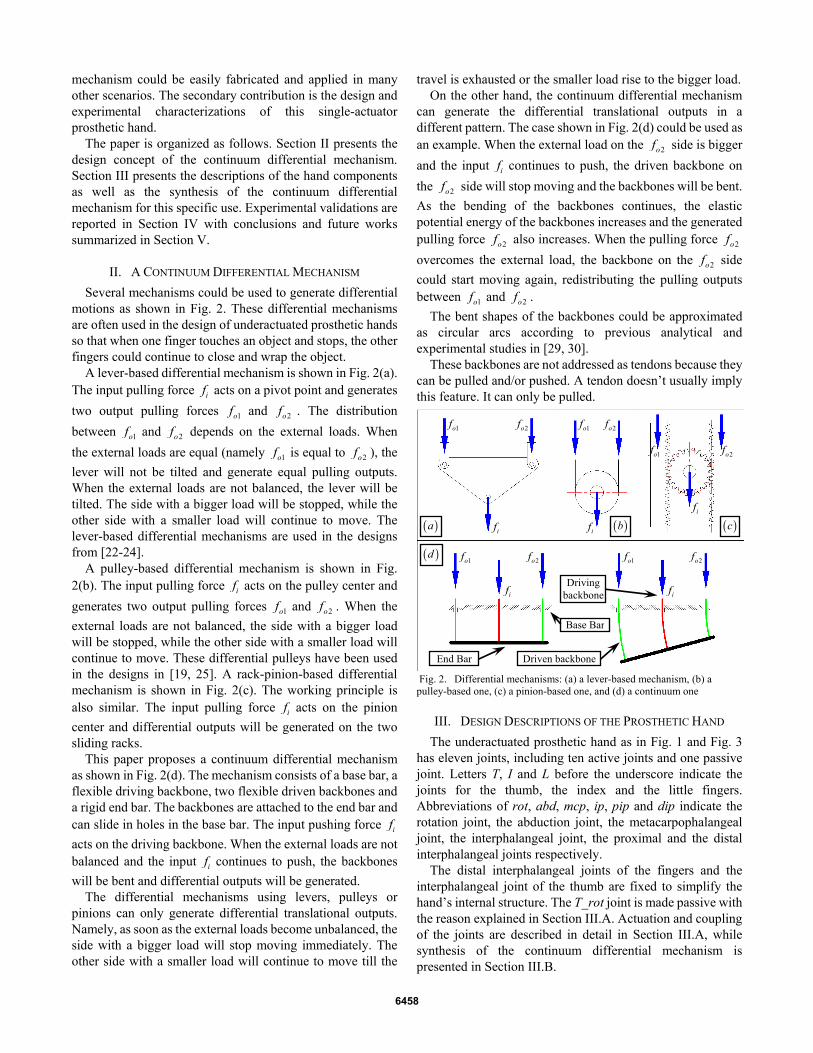
Several mechanisms could be used to generate differential motions as shown in Fig. 2. These differential mechanisms are often used in the design of underactuated prosthetic hands so that when one finger touches an object and stops, the other fingers could continue to close and wrap the object.
A lever-based differential mechanism is shown in Fig. 2(a). The input pulling force if acts on a pivot point and generates
two output pulling forces 1of and 2of . The distribution
between 1of and 2of depends on the external loads. When
the external loads are equal (namely 1of is equal to 2of ), the
lever will not be tilted and generate equal pulling outputs. When the external loads are not balanced, the lever will be tilted. The side with a bigger load will be stopped, while the other side with a smaller load will continue to move. The lever-based differential mechanisms are used in the designs from [22-24].
A pulley-based differential mechanism is shown in Fig. 2(b). The input pulling force if acts on the pulley center and
generates two output pulling forces 1of and 2of . When the
external loads are not balanced, the side with a bigger load will be stopped, while the other side with a smaller load will continue to move. These differential pulleys have been used in the designs in [19, 25]. A rack-pinion-based differential mechanism is shown in Fig. 2(c). The working principle is also similar. The input pulling force if acts on the pinion
center and differential outputs will be generated on the two sliding racks.
This paper proposes a continuum differential mechanism as shown in Fig. 2(d). The mechanism consists of a base bar, a flexible driving backbone, two flexible driven backbones and a rigid end bar. The backbones are attached to the end bar and can slide in holes in the base bar. The input pushing force if
acts on the driving backbone. When the external loads are not balanced and the input if continues to push, the backbones
will be bent and differential outputs will be generated. The differential mechanisms using levers, pulleys or
pinions can only generate differential translational outputs. Namely, as soon as the external loads become unbalanced, the side with a bigger load will stop moving immediately. The other side with a smaller load will continue to move till the
travel is exhausted or the smaller load rise to the bigger load. On the other hand, the continuum differential mechanism
can generate the differential translational outputs in a different pattern. The case shown in Fig. 2(d) could be used as an example. When the external load on the 2of side is bigger
and the input if continues to push, the driven backbone on
the 2of side will stop moving and the backbones will be bent.
As the bending of the backbones continues, the elastic potential energy of the backbones increases and the generated pulling force 2of also increases. When the pulling force 2of
overcomes the external load, the backbone on the 2of side
could start moving again, redistributing the pulling outputs between 1of and 2of .
The bent shapes of the backbones could be approximated as circular arcs according to previous analytical and experimental studies in [29, 30].
These backbones are not addressed as tendons because they can be pulled and/or pushed. A tendon doesn’t usually imply this feature. It can only be pulled.
Fig. 2. Differential mechanisms: (a) a lever-based mechanism, (b) a
pulley-based one, (c) a pinion-based one, and (d) a continuum one
III. DESIGN DESCRIPTIONS OF THE PROSTHETIC HAND
The underactuated prosthetic hand as in Fig. 1 and Fig. 3 has eleven joints, including ten active joints and one passive joint. Letters T, I and L before the underscore indicate the joints for the thumb, the index and the little fingers. Abbreviations of rot, abd, mcp, ip, pip and dip indicate the rotation joint, the abduction joint, the metacarpophalangeal joint, the interphalangeal joint, the proximal and the distal interphalangeal joints respectively.
The distal interphalangeal joints of the fingers and the interphalangeal joint of the thumb are fixed to simplify the hand’s internal structure. The T_rot joint is made passive with the reason explained in Section III.A. Actuation and coupling of the joints are described in detail in Section III.A, while synthesis of the continuum differential mechanism is presented in Section III.B.
( )a ( )b ( )c
( )d
if if
if
if
if
1of 1of
1of
1of 1of
2of 2of
2of
2of 2of
Base Bar
Driving backbone
Driven backbone End Bar
6458

Fig. 3. The single-actuator prosthetic hand
A. Actuation of the Fingers
Structures of the index, the middle, the ring and the little fingers are similar. Figure 4 only shows the index finger. Motions of the I_mcp joint and the I_pip joint are coupled through a coupler. A torsional spring is installed at the I_pip joint. When the crank is rotated by pulling the BI backbone, the I_mcp joint will rotate first. Then if the proximal phalange encounters an object, continuing to pull the BI backbone will close the I_pip joint.
The BI backbone is made from a super-elastic nitinol rod with a diameter of 1.2mm. The connection between the backbone and the crank is shown in the inset of Fig. 4. The backbone can tolerate the generated deflection when the crank is rotated.
Fig. 4. The index finger of the prosthetic hand
The structure of the thumb is shown in Fig. 5. The T_abd joint and the T_mcp joint are made coupled via the coupler #2. A torsional spring is installed at the T_mcp joint so that the T_abd joint would rotate first. When the thumb metacarpal is stopped by an object, the T_mcp will continue to close. The T_abd joint is actuated by the translation of the T_rot shaft via the coupler #1. Since the axes of the T_mcp and the T_abd joints are not parallel, the coupler #2 is made from a super-elastic nitinol rod with a diameter of 1.2mm to allow deflections on the coupler. Two ends of the coupler #2 have the connections similar to the one shown in the inset of Fig. 4.
Different grasping patterns (e.g. grasp of a coke can or grasp of a CD) need the T_rot joint at different angles. All the active joints of the hand shall be coupled since the hand is
expected to have only one actuator. If the T_rot joint is active, it might be difficult to design such a mechanism to allow the T_rot joint to realize these distinct grasping patterns. Hence the T_rot joint was made passive. Its angle could be set by the healthy hand. A locking ring indicated in Fig. 5 could be tightened to adjust the friction of the passive T_rot joint.
The T_rot shaft sits on a pair of linear bearings and it is connected to the back of a rack. The rack is actuated by a pinion that is attached to a motor (Maxon DXG-10L, nominal voltage 3.0v) with a customized planetary gearhead (gear ratio 348:1).
The index, the middle, the ring and the little fingers are actuated by four backbones, BI, BM, BR and BL, as shown in Fig. 5. The four backbones are the outputs of the continuum differential mechanism. The differential mechanism has one input backbone which is also attached to the rack via a fixture. Coupling between the input of the continuum differential mechanism and the T_rot joint has been carefully adjusted to allow a pinch motion.
Fig. 5. The thumb and the differential mechanism of the prosthetic hand:
(a) the assembly
B. Synthesis of the Continuum Differential Mechanism
The continuum differential mechanism of the prosthetic hand shown in Fig. 6 has a layered structure. It consists of three basic units (Unit #1, Unit #2 and Unit #3) and one unit is shown in Fig. 2(d). Four output backbones, BI, BM, BR and BL, are for the index, the middle, the ring and the little fingers. The input backbone Bin is fixed to the rack through a fixture. The Bin backbone drives the B1 and B2 backbones to drive the BI, BM, BR and BL, backbones. Please note that the B1 and B2 backbones are connected from Unit #3 to Unit #1 and Unit #2 respectively.
All the backbones are made from super-elastic nitinol rods with a diameter of 1.2mm. Main design parameters of this mechanism include the width variables (w1, w2 and w3) and the length variables (l1, l2 and l3) as indicated in Fig. 6. The design goals include i) the realization of various grasping patterns of the fingers, and ii) minimization of the differential mechanism’s overall size.
T_abd
T_mcp
Coupler #1
Coupler #2
T_rot Shaft
Locking ring
Rack & pinion
Continuum Differential Mechanism
Linear bearingMotor
BI
BM
BR
BL
( )a
Backbone BI
Coupler
I_pip
I_mcpCrank
Continuum Differential Mechanism
T_abd
T_mcp
T_ip
I_pip
I_mcp
I_dip
T_rot
Actuator
Battery pack
L_pip
L_mcp
L_dip
Continuum Differential Mechanism
6459

The four elastic backbones (BI, BM, BR and BL) are routed from the fingers to the continuum differential mechanisms. They should be kept straight (or almost straight) to avoid stress concentration and/or reduce possible frictions with the hand’s internal structures. Then the arrangement of the fingers determines the arrangement of the BI, BM, BR and BL backbones. The width variables are hence determined as follows: w1 = w2 = 10mm, w3 = 20mm.
These nitinol backbones all are 1.2mm in diameter. If a 2% elastic strain is allowed as in Eq. (1), the minimal bending radius of these backbones could be derived as in Eq. (2):
2%backbonestrain
bending
r
rε = ≤ (1)
50 30bending backboner r mm≥ = (2)
The lengths (l1, l2 and l3) of the three units in the differential mechanism should be long enough in order not to violate the bending constraint in Eq. (2). These lengths should also be minimized to reduce the mechanism’s overall size.
The BI, BM, BR and BL backbones shall be pulled for about 9.3mm to 9.8mm to fully close the four fingers. For the design of this differential mechanism, these backbones are assumed to have 10mm travels.
An assumption was made for the design of the differential mechanism that the difference between the actuated distances of the backbones for the adjacent fingers would not exceed 5mm. For example, if the BI backbone can only be pulled for 2mm before the index finger is stopped by an object, the BM backbone would only need to be pulled less than 7mm to wrap this object. This assumption is made based on an observation that a daily-life object to be grasped usually has a smooth outer shape. The amounts of backbone actuation distances for adjacent fingers should be close. This assumption helps reduce the overall size of the differential mechanism.
The design of Unit #1 could be used as an example. The most severe bending of the backbones occurs when the BI backbone is not pulled while the BM backbone is pulled for 5mm. Then the lengths of the BI and the BM backbones within Unit #1 are l1 and l1+5mm respectively. Then the geometrical relations in Eq. (3) hold referring to Fig. 6(b.2), which leads to Eq. (4). The bending constraint in Eq. (2) also applies to r1. Substituting the w1 value, the l1 value is determined to be 7.5mm as in Eq. (5)
( )1 1 1
1 1 1 12 5
r l
r w l mm
θθ
= + = +
(3)
1 1 1 11
1 1 1
2
2 5 5
r l w lr
r w l mm mm= =
+ + (4)
1 101 11
230 7.5
5w mmw l
mm l mmmm
=≥ ⎯⎯⎯⎯→ ≥ (5)
Similarly, the l2 value is also determined to be 7.5mm. The most severe bending of the Unit #3 occurs under
multiple scenarios. One of them corresponds to the case when the BI, BM, BR and BL backbones are actuated for 0mm, 0mm, 5mm and 10mm respectively. The l3 value can then be
determined to be at least 13.125mm, using the bending constraint as in Eq. (2), the geometrical relations similar to the ones as in Eq. (3), and the w3 value of 20mm.
Fig. 6. Schematic of the continuum differential mechanism: (a) the CAD
model and the assembly, (b) the mechanism at the original or actuated configurations
A MATLAB simulation as in Fig. 7 was carried out to verify under an arbitrary grasping pattern the bending constraint as in Eq. (2) is never violated. What’s more, such an exhaustive simulation also generates enveloping dimensions for this differential mechanism such that internal hand structure will not interfere with the motions of the differential mechanism.
Fig. 7. Matlab simulation of the configurations of the continuum
differential mechanism
-40 -20 0 20 40
-20
0
20
[0 0 0 0]
-40 -20 0 20 40
-20
0
20
[5 0 0 0]
-40 -20 0 20 40
-20
0
20
[0 5 0 0]
-40 -20 0 20 40
-20
0
20
[0 0 5 0]
-40 -20 0 20 40
-20
0
20
[0 0 0 5]
-40 -20 0 20 40
-20
0
20
[0 5 5 0]
-40 -20 0 20 40
-20
0
20
[5 0 0 5]
-40 -20 0 20 40
-20
0
20
[10 5 0 0]
-40 -20 0 20 40
-20
0
20
[0 0 5 10]
-40 -20 0 20 40
-20
0
20
[10 5 5 5]
-40 -20 0 20 40
-20
0
20
[10 5 5 10]
-40 -20 0 20 40
-20
0
20
[10 10 10 10]
Unit #1
( )a
BI BMBRBL
1w2w
3w
1l2l
3l
1r
1θ
Bin
Unit #2
Unit #3
B1
B2
( ).1b
( ).2b
6460

In Fig. 7, the numbers in the titles of the subplots represent the actuation lengths of the BI, BM, BR and BL backbones. Unit for the X and Y axes of the subplots is millimeter.
The simulations in Fig. 7 are purely geometrical. Actual shapes of the backbones within the differential mechanism also depend on the grasping force equilibrium.
The l3 value was rounded to 13.5mm to ease the fabrication process.
IV. EXPERIMENTAL VERIFICATIONS
A series of experiments were carried out to demonstrate the effectiveness of this single-actuator prosthetic hand.
A. Grasping Capabilities
A set of grasping experiments were first carried out to check the hand’s capabilities in grasping various daily-life objects. The experimental setup is shown in Fig. 8. The motor is powered by a linear DC power supply. The power supply has an adjustable built-in current limit switch so that the motor can be protected during a power grip. The internal batteries were not used at this time.
A double pole double throw switch was used to turn on/off the motor. Direction of the current can be changed to rotate or reverse the motor so as to open and close the hand. The switch can be replaced by a myoelectric sensor in the future.
Then the hand was used to grasp various daily-life objects, including a tape roll, a tennis ball, a coke can, a flash light, a CD, a cup, a jar and a key, as shown in Fig. 9. The fingers adapted to different shapes of the objects due to the continuum differential mechanism and the adjustable T_rot joint. The motor is always powered on at 3.0V till the grasp is completed and the motor is stalled. A clutch might be needed in a future design to avoid overheating the motor as well as reduce the battery use.
A few representative grasping motions, as well as a zoom-in view of the continuum differential mechanism, can be viewed in the multimedia extension.
Fig. 8. Setup for the grasping experiments
B. Quantification of the Grasping Forces
With the grasping capabilities shown in Section IV.A, the grasping forces generated by the hand were then quantified.
The experimental setup is shown in Fig. 10. A 3-axis force sensor (K3D60 from ME-Meßsysteme GmbH) was used. Two adapter plates made from acrylics were attached to the two sides of the sensor so that the forces from the hand fingers
could eventually all exert on the force sensor. The sensor was hung above the palm to reduce the disturbances from the sensor’s own weight.
During one grip, readings from the sensor could be seen in Fig. 10(b.1). The total grasping force is the combination of the XYZ components with the non-zero initial values subtracted. The hand motor was powered from 1.0V to 3.8V and the grasping forces are plotted in Fig. 10(b.2).
Fig. 9. Grasping patterns of various daily-life objects
Fig. 10. Grasping force quantification: (a) the experimental setup, and (b) the results
1 1.5 2 2.5 3 3.5 40
1
2
3
4
5
6
Input Voltage (V)
Gra
spin
g Fo
rce
(N)
2 4 6 8 10 12
-2
-1
0
1
2
3
4
5
6
7
Time (s)
For
ce (
N)
x-axisy-axisz-axis
( )a ( ).1bSensor
( ).2b
Non-zero initial values
Nominal voltage at 3.0v
( )a ( )b
Switch
DC power supply
6461

The motor’s nominal voltage is 3.0V, at which the hand generates a grasping force of 3.81N. The grasping force could be boosted to 5.06N for a short period of time by powering the motor at 3.8V.
V. CONCLUSIONS AND FUTURE WORK
This paper presents the design and the experimental characterizations of an underactuated prosthetic hand with one actuator using a continuum differential mechanism.
Differential motions of the fingers were successfully realized. The hand could grasp various daily-life objects, demonstrating a lot of potentials of the proposed design.
A few modifications will soon be introduced to improve the current design in the near future. First of all, a clutch shall be incorporated to lock the motor shaft once a grasp is formed. This will prevent stalling the motor and also save the battery. Next, the rack and pinion might be replaced by an alternative mechanism to realize higher grasping forces. The current grasping forces are not always enough. Last, the motor switch could be replaced by a myoelectric sensor so that the prosthetic hand can be tried out by an amputee.
REFERENCES [1] M. Santello, M. Flanders, and J. F. Soechting, "Postural Hand Synergies
for Tool Use," The Journal of Neuroscience, vol. 18, No.23, pp. 10105-10115, Dec 1998.
[2] A. Bicchi, "Hands for Dexterous Manipulation and Robust Grasping: a Difficult Road toward Simplicity," IEEE Transactions on Robotics and Automation, vol. 16, No.6, pp. 652-662, Dec 2000.
[3] H. Liu, P. Meusel, N. Seitz, B. Willberg, G. Hirzinger, M. H. Jin, Y. W. Liu, R. Wei, and Z. W. Xie, "The Modular Multisensory DLR-HIT-Hand," Mechanism and Machine Theory, vol. 42, No.5, pp. 612-625, May 2007.
[4] M. Grebenstein, M. Chalon, W. Friedl, S. Haddadin, T. Wimböck, G. Hirzinger, and R. Siegwart, "The Hand of the DLR Hand Arm System: Designed for Interaction," International Journal of Robotics Research, vol. 31, No.13, pp. 1531-1555, 2012.
[5] T. Wimböck, B. Jahn, and G. Hirzinger, "Synergy Level Impedance Control for Multifingered Hands," in IEEE/RSJ International Conference on Intelligent Robots and Systems (IROS), San Francisco, CA, USA, 2011, pp. 973-979.
[6] F. Ficuciello, G. Palli, C. Melchiorri, and B. Siciliano, "Experimental evaluation of Postural Synergies during Reach to Grasp with the UB Hand IV," in IEEE/RSJ International Conference on Intelligent Robots and Systems (IROS), San Francisco, CA, USA, 2011, pp. 1775-1780.
[7] J. Rosell, R. Suárez, C. Rosales, and A. Pérez, "Autonomous Motion Planning of a Hand-Arm Robotic System Based on Captured Human-like Hand Postures," Autonomous Robots, vol. 31, No.1, pp. 87-102, 2011.
[8] A. Zhang, M. Malhotra, and Y. Matsuoka, "Musical Piano Performance by the ACT Hand," in IEEE International Conference on Robotics and Automation (ICRA), Shanghai, China, 2011, pp. 3536-3541.
[9] C. Y. Brown and H. H. Asada, "Inter-Finger Coordination and Postural Synergies in Robot Hands via Mechanical Implementation of Principal Components Analysis," in IEEE/RSJ International Conference on Intelligent Robots and Systems (IROS), San Diego, CA, USA, 2007, pp. 2877-2882.
[10] K. Xu, Y. Du, H. Liu, X. Sheng, and X. Zhu, "Mechanical Implementation of Postural Synergies of an Underactuated Prosthetic Hand," in International Conference on Intelligent Robotics and Applications (ICIRA) Busan, Korea, 2013, pp. 463-474.
[11] K. Xu, H. Liu, Y. Du, X. Sheng, and X. Zhu, "Mechanical Implementation of Postural Synergies Using a Simple Continuum Mechanism," in IEEE International Conference on Robotics and Automation (ICRA), Hong Kong, China, 2014, pp. 1348-1353.
[12] K. Xu, H. Liu, Y. Du, and X. Zhu, "Design of an Underactuated Anthropomorphic Hand with Mechanically Implemented Postural Synergies," Advanced Robotics, vol. 28, No.21, pp. 1459-1474, Nov 2014.
[13] M. R. Cutkosky, "On Grasp Choice, Grasp Models, and the Design of Hands for Manufacturing Tasks," IEEE Transactions on Robotics and Automation, vol. 5, No.3, pp. 269-279, June 1989.
[14] T. Feix, R. Pawlik, H.-B. Schmiedmayer, J. Romero, and D. Kragić, "A Comprehensive Grasp Taxonomy," in Robotics, Science and Systems Conference (RSS), Seattle, Washington, USA, 2009.
[15] J. Z. Zheng, S. De La Rosa, and A. M. Dollar, "An Investigation of Grasp Type and Frequency in Daily Household and Machine Shop Tasks," in IEEE International Conference on Robotics and Automation (ICRA), Shanghai, China, 2011, pp. 4169-4175.
[16] M. C. Carrozza, G. Cappiello, S. Micera, B. B. Edin, L. Beccai, and C. Cipriani, "Design of a Cybernetic Hand for Perception and Action," Biological Cybernetics, vol. 95, No.6, pp. 629-644, 2006.
[17] L. Zollo, S. Roccella, E. Guglielmelli, M. C. Carrozza, and P. Dario, "Biomechatronic Design and Control of an Anthropomorphic Artificial Hand for Prosthetic and Robotic Applications," IEEE/ASME Transaction on Mechatronics, vol. 12, No.4, pp. 418-429, Aug 2007.
[18] K. B. Fite, T. J. Withrow, X. Shen, K. W. Wait, J. E. Mitchell, and M. Goldfarb, "A Gas-Actuated Anthropomorphic Prosthesis for Transhumeral Amputees," IEEE Transactions on Robotics, vol. 24, No.1, pp. 159-169, Feb 2008.
[19] S. A. Dalley, T. E. Wiste, T. J. Withrow, and M. Goldfarb, "Design of a Multifunctional Anthropomorphic Prosthetic Hand With Extrinsic Actuation," IEEE/ASME Transaction on Mechatronics, vol. 14, No.6, pp. 699-706, Nov 2009.
[20] Y. J. Shin, K.-H. Rew, K.-S. Kim, and S. Kim, "Development of Anthropomorphic Robot Hand with Dual-Mode Twisting Actuation and Electromagnetic Joint Locking Mechanism," in IEEE International Conference on Robotics and Automation (ICRA), Karlsruhe, Germany, 2013, pp. 2759-2764.
[21] J. T. Belter, J. L. Segil, A. M. Dollar, and R. F. Weir, "Mechanical Design and Performance Specifications of Anthropomorphic Prosthetic Hands: A Review," Journal of Rehabilitation Research & Development, vol. 50, No.5, pp. 599-618, 2013.
[22] N. Fukaya, S. Toyama, T. Asfour, and R. Dillmann, "Design of the TUAT/Karlsruhe Humanoid Hand," in IEEE/RSJ International Conference on Intelligent Robots and Systems (IROS), Takamatsu, Japan, 2000, pp. 1754-1759.
[23] Y. Kamikawa and T. Maeno, "Underactuated Five-Finger Prosthetic Hand Inspired by Grasping Force Distribution of Humans," in IEEE/RSJ International Conference on Intelligent Robots and Systems (IROS), Nice, France, 2008, pp. 717-722.
[24] M. Baril, T. Laliberté, C. Gosselin, and F. Routhier, "On the Design of a Mechanically Programmable Underactuated Anthropomorphic Prosthetic Gripper," Journal of Mechanical Design, vol. 135, No.12, pp. 121008-1, Oct 2013.
[25] C. Gosselin, F. Pelletier, and T. Laliberté, "An Anthropomorphic Underactuated Robotic Hand with 15 Dofs and a Single Actuator," in IEEE International Conference on Robotics and Automation (ICRA), Pasadena, CA, USA, 2008, pp. 749-754.
[26] J. T. Belter and A. M. Dollar, "Novel Differential Mechanism Enabling Two DOF from a Single Actuator: Application to a Prosthetic Hand," in IEEE International Conference on Rehabilitation Robotics (ICORR), Seattle, Washington, USA, 2013, pp. 1-6.
[27] M. C. Carrozza, G. Cappiello, G. Stellin, F. Zaccone, F. Vecchi, S. Micera, and P. Dario, "A Cosmetic Prosthetic Hand with Tendon Driven Under-Actuated Mechanism and Compliant Joints: Ongoing Research and Preliminary Results," in IEEE International Conference on Robotics and Automation (ICRA), Barcelona, Spain, 2005, pp. 2661-2666.
[28] A. M. Dollar and R. D. Howe, "The Highly Adaptive SDM Hand: Design and Performance Evaluation," International Journal of Robotics Research, vol. 29, No.5, pp. 585-597, April 2010.
[29] K. Xu and N. Simaan, "An Investigation of the Intrinsic Force Sensing Capabilities of Continuum Robots," IEEE Transactions on Robotics, vol. 24, No.3, pp. 576-587, June 2008.
[30] K. Xu and N. Simaan, "Analytic Formulation for the Kinematics, Statics and Shape Restoration of Multibackbone Continuum Robots via Elliptic Integrals," Journal of Mechanisms and Robotics, vol. 2, No.011006, pp. 1-13, Feb 2010.
6462