A SIMPLE TELESCOPE ANYONE - Ken PressWhile amateur astronomy, both as a hobby and as an aid to...
102
1 A SMALL, SIMPLE, BEGINNER’S TELESCOPE ANYONE CAN BUILD Alan Binder & Ken Graun Copyright ©2015 by Alan Binder & Ken Graun This manual may only be printed and/or copied for noncommercial purposes, i.e. for personal use and for use by astronomy and/or telescope making clubs and classes.
Transcript of A SIMPLE TELESCOPE ANYONE - Ken PressWhile amateur astronomy, both as a hobby and as an aid to...

1
A SMALL, SIMPLE,
BEGINNER’S TELESCOPE
ANYONE CAN BUILD
Alan Binder & Ken Graun
Copyright ©2015 by Alan Binder & Ken Graun
This manual may only be printed and/or copied for noncommercial
purposes, i.e. for personal use and for use by astronomy and/or
telescope making clubs and classes.

2
A SMALL, SIMPLE,
BEGINNER’S TELESCOPE
ANYONE CAN BUILD
Alan Binder (AB) & Ken Graun (KG)
Part I: Introduction and Background
Introduction
Astronomy and telescope making are unique fields in the
physical sciences because a person with no formal training can not
only enjoy both as hobbies, but can also do professional level
work. For example, many variable star observations are made by
amateur astronomers, since there are far to few professional
astronomers and they have far to little telescope observing time to
continuously observe the myriad of variable stars in the nighttime
sky. Similarly, amateurs contribute significantly to the search for
comets, Near Earth Asteroids and Super Nova stars, as well as the
study of features of Jupiter and Mars — just to mention a few. And
many of these amateurs use telescopes they built themselves.
While amateur astronomy, both as a hobby and as an aid to
professional astronomers, is booming, amateur telescope making is
declining from its heydays in the 40s, 50s and 60s. This is mainly
due to the numerous telescopes available from commercial
vendors. This is, in our view, unfortunate, since making a telescope
and observing with it is extremely satisfying and, when one can
make the optics for a telescope, one is not limited to that which is
available commercially, i.e., you can make a telescope to exactly
serve your specific needs.

3
Figure I-1: A simple, 4-inch, 36-inch focal length (FL), Newtonian Reflector with a
simple equatorial mount on a cement pillar in the atrium of AB’s house. This telescope
also has a tripod that AB uses when he is camping or wants to observe at a different
location. Building this kind of telescope and mount requires only simple wood and metal
working tools.

4
Figure I-2: A classic, 4-inch, 29-inch FL, Newtonian Reflector with a classic
German Equatorial Mount, a clock drive, slow motion controls and setting circles in one
of the domes of AB’s observatory. Building this kind of telescope and mount requires the
use of a lath, a mill, and wood working tools.
Both authors have ground and polished mirrors and lenses for
various telescopes over many decades. AB has made the mirrors
for four, 4-inch Newtonian reflectors (e.g., Figures I-1 and I-2);
three optical flats and a very long focal (46 foot) mirror for a solar
telescope; a 4-inch Dall-Kirkham Cassegrain telescope; the 3-inch
(2.8-inch clear aperture), 17-foot focal length lens and three
Huygens eyepieces for a replica of the long-focal refractors of the
mid-1600s (Figures I-3 and I-4); the lens and Kepler eyepieces for
three replicas of the telescopes of the early 1600s, and the lenses
and eyepieces for replicas of three of Galileo’s most famous
telescopes (Figure I-5).

5
Figure I-3: AB’s 17-foot replica of the long-focal, non-achromatic refractors and mounts
of the second half of the 17th
century.
Similarly, KG has made the mirrors for one 6-inch and two
4-inch Newtonian telescopes and the lens and eyepiece for a
Galilean telescope.
6
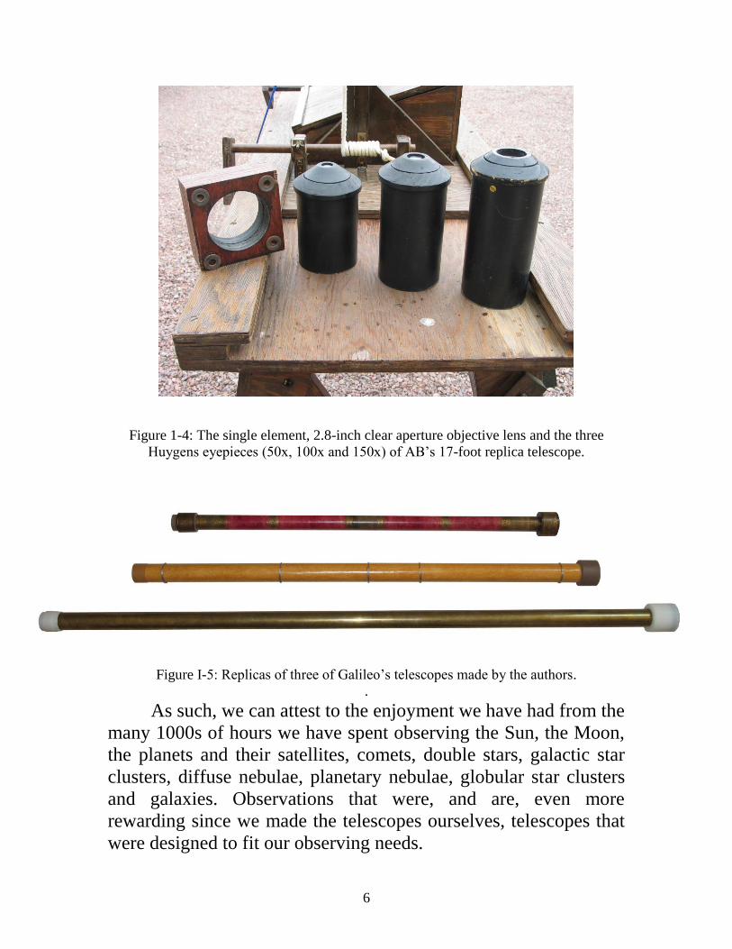
Figure 1-4: The single element, 2.8-inch clear aperture objective lens and the three
Huygens eyepieces (50x, 100x and 150x) of AB’s 17-foot replica telescope.
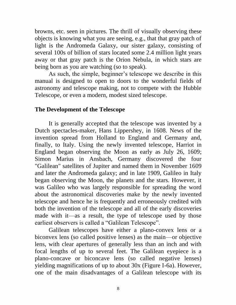
Figure I-5: Replicas of three of Galileo’s telescopes made by the authors.
.
As such, we can attest to the enjoyment we have had from the
many 1000s of hours we have spent observing the Sun, the Moon,
the planets and their satellites, comets, double stars, galactic star
clusters, diffuse nebulae, planetary nebulae, globular star clusters
and galaxies. Observations that were, and are, even more
rewarding since we made the telescopes ourselves, telescopes that
were designed to fit our observing needs.

7
It is with this background that we decided to write this
instruction manual and make the accompanying video on how to
make a small (1.5-inch), simple, refracting telescope for anyone
who is interested in amateur astronomy and amateur telescope
making and does not know how to start. By doing so, we hope to
awaken the interest of people, especially young people, in these
two fields of scientific endeavor—interests that could led to
careers in either of these two fields in this age of space exploration.
How Useful is a Small, Simple Telescope?
There is a general misconception among those who have
never looked through an astronomical telescope that leads to a
question often asked; “Don’t you have to have a big telescope to
see anything?” The answer is a resounding “No.” AB’s first
telescope was a 25x, 1½-inch, achromatic refractor his dad used
for hunting! With it, AB observed the craters, marae and
mountains of the Moon, lunar eclipses, sunspots and a solar
eclipse, the phases of Venus, Jupiter and it’s two main belts and its
four major satellites, a few asteroids, Saturn’s rings and Saturn’s
largest satellite—Titan, Uranus, Neptune, numerous double stars,
the Orion Nebula and a few other diffuse or gaseous nebulae,
several galactic star clusters, a planetary nebula, many globular
clusters, the Great Andromeda Galaxy and a couple of other
galaxies. To drive this point home, the reader can go to Appendix
A to see a list some 130 objects he or she can observe with the
simple telescope we describe in this manual.
However, one note of caution: You will never see, through
any telescope, the detail of any celestial object that is captured,
often in color, by a long exposure image, e.g. the beautiful pictures
from the Hubble Space Telescope. The human eye is only capable
of seeing, e.g., galaxies, gaseous nebulae and most globular star
clusters, as gray patches of light even in modest sized telescopes.
Also, the colors of Mars, the colors of the cloud belts of Jupiter
and those of stars are just faint hues—not the brilliant reds,
8
browns, etc. seen in pictures. The thrill of visually observing these
objects is knowing what you are seeing, e.g., that that gray patch of
light is the Andromeda Galaxy, our sister galaxy, consisting of
several 100s of billion of stars located some 2.4 million light years
away or that gray patch is the Orion Nebula, in which stars are
being born as you are watching (so to speak).
As such, the simple, beginner’s telescope we describe in this
manual is designed to open to doors to the wonderful fields of
astronomy and telescope making, not to compete with the Hubble
Telescope, or even a modern, modest sized telescope.
The Development of the Telescope
It is generally accepted that the telescope was invented by a
Dutch spectacles-maker, Hans Lippershey, in 1608. News of the
invention spread from Holland to England and Germany and,
finally, to Italy. Using the newly invented telescope, Harriot in
England began observing the Moon as early as July 26, 1609;
Simon Marius in Ansbach, Germany discovered the four
"Galilean" satellites of Jupiter and named them in November 1609
and later the Andromeda galaxy; and in late 1909, Galileo in Italy
began observing the Moon, the planets and the stars. However, it
was Galileo who was largely responsible for spreading the word
about the astronomical discoveries make by the newly invented
telescope and hence he is frequently and erroneously credited with
both the invention of the telescope and all of the early discoveries
made with it—as a result, the type of telescope used by those
earliest observers is called a “Galilean Telescope”.
Galilean telescopes have either a plano-convex lens or a
biconvex lens (so called positive lenses) as the main—or objective
lens, with clear apertures of generally less than an inch and with
focal lengths of up to several feet. The Galilean eyepiece is a
plano-concave or biconcave lens (so called negative lenses)
yielding magnifications of up to about 30x (Figure I-6a). However,
one of the main disadvantages of a Galilean telescope with its

9
negative eyepiece, is that the field of view is extremely small.
When looking through the replicas of Galileo’s telescopes we have
made, the view is quite unpleasant, since it is like looking through
a soda straw! This makes it difficult to find and track objects—
even the Moon.
In 1611 Kepler made the first improvement to the
astronomical telescope by suggesting that the negative Galilean
eyepiece lens be replaced by a positive lens (Figure I-6b). The
result of using a Keplerian eyepiece is that, for the same power as a
Galilean telescope, the field of view is quite large and the view is
very pleasant.
However, even after Kepler’s suggested improvement of the
early telescopes, two major defects remained. Since the objective
lenses used were single element lenses (that is, they consisted of
just one lens), they suffered from both spherical and chromatic
aberration. In spherical aberration, the light rays near the center of
the lens come to focus at a greater distance from the lens than the
light rays at the edges of the lens (Figure I-7a). In chromatic
aberration, the rays of
Figure I-6: (a) Optical configuration of a Galilean telescope with a single element,
objective lens and a negative eyepiece lens; (b) Optical configuration of a Keplerian
telescope with a single element, objective lens and a positive eyepiece lens.

10
light of different colors come to focus at different distances from
the lens, e.g., the red light focus is longer that that of blue light
(Figure I-7b).
Figure I-7: (a) Ray traces showing the effects of spherical aberration on the focus points
of rays passing through the lens near the center of a single element lens and those passing
through the lens near the edges of the lens; (b) Ray traces showing the effects of
chromatic aberration on the focus points of rays of blue light and those of red light.
These two defects of a single element lens means that the
image produced is somewhat blurry. By the middle of the 1600s,
astronomers and telescope makers, like Huygens and Hevelius,
found that the effects of spherical and chromatic aberrations could
be compensated for by making the focal length of the objective
lens very long. However, both of these effects depend on the
square of the diameter of the objective. Thus, while a 1-inch
diameter objective with a focal length of 40-inches or more is
essentially color-free, i.e., achromatic and essentially free from
spherical aberration, the focal length of a 2-inch diameter lens
must be 160-inches or more, that is, 13-feet to be nearly defect-
free. As the reader can surmise, this solution to the aberration
problems of single lenses via increasing focal lengths has it limits
and led to telescopes of the second half of the 1600s having focal
lengths of 100- to 200-feet, and even more, while still having
objective lenses no larger than 6 to 8 inches in diameter, e.g.,
11
Hevelius’ 150-foot telescope (Figure I-8). Needless to say,
telescopes of those lengths were very difficult to use, but as AB
demonstrated with his 2.8-inch clear aperture, 17-foot replica of
the telescopes of that era (Figures I-3 and I-4), modest sized
telescope of that era were very capable astronomical instruments
(Appendix B; Binder, 1992; Binder, 2010a; Binder, 2010b).
There are two other solutions to the problems of telescopes
caused by spherical and chromatic aberration. First, if the
objective lens is made with two lenses, one positive and one
negative, with the two lenses made from glasses with different
dispersions, i.e., different refractive indexes for the different colors
of light, the resulting two element objective is nearly achromatic
and free from spherical aberration, even for telescopes with very
short focal lengths. However, this solution was not discovered until
1733 by Hall and, of course, making an achromat, as such lenses
are called, is not a simple task.

12
Figure I-8: Hevelius’ 150-foot telescope.
Second, it was recognized very early that if a parabolic
mirror could be ground and polished, it would be both achromatic
and have no spherical aberration. However, the “if” was the
problem, since no one initially knew how to grind and polish such
a mirror and mirrors were made of metal, rather than glass, until
the middle of the 1800s. Nevertheless, in 1668 Newton succeeded
in making the first, small (1¼-inch diameter mirror with a 6¼-inch
focal length) working reflecting telescope (Figures I-9a and I-9b),
but it
13
a b
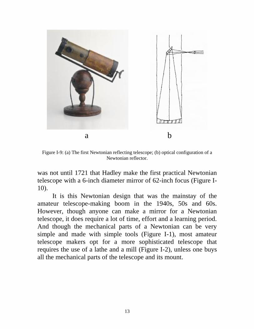
Figure I-9: (a) The first Newtonian reflecting telescope; (b) optical configuration of a
Newtonian reflector.
was not until 1721 that Hadley make the first practical Newtonian
telescope with a 6-inch diameter mirror of 62-inch focus (Figure I-
10).
It is this Newtonian design that was the mainstay of the
amateur telescope-making boom in the 1940s, 50s and 60s.
However, though anyone can make a mirror for a Newtonian
telescope, it does require a lot of time, effort and a learning period.
And though the mechanical parts of a Newtonian can be very
simple and made with simple tools (Figure I-1), most amateur
telescope makers opt for a more sophisticated telescope that
requires the use of a lathe and a mill (Figure I-2), unless one buys
all the mechanical parts of the telescope and its mount.

14
Figure I-10: Hadley’s 6-inch diameter, 62-inch focal length Newtonian telescope.
The above discussions of telescopes is sufficient for the
purposes of this manual, but any reader who is interested in
learning more about the development of the astronomical telescope
should read King’s excellent book, “The History of the Telescope”
(Appendix B). And anyone who is interested in making telescopes
more advanced than the one described below should read any of a
number of excellent books on telescope making, e.g., “Amateur
Telescope Making, Book One” (Appendix B).
A Simple Telescope for the Beginner
Based on the years of experience the authors have had
making and observing with telescopes, both modern and replicas of
historical telescopes, we have designed a very simple, non-
achromatic refractor with a simple mount that anyone can make in

15
a short time using 1) the lens grinding and polishing kit we can
supply, 2) items purchased from a hardware store and other stores
and 3) simple tools.
The telescope optics consist of a single element (non-
achromatic) plano-convex objective lens with a clear diameter of
1½-inch (1¾-inch full diameter) with a 60-inch focal length (FL)
and two plano-convex, Keplerian eyepieces with 2-inch and 1-inch
focal lengths, yielding 30x and 60x.
The kit (Figure I-11), which we supply via Ken Press for
$20.00 plus $6.00 shipping (we make no profit - rather lose money
on these kits), consists of the following:
1) Two 1¾-inch diameter plate glass, beveled blanks for
making the objective lens,
2) Two 11/4-inch diameter, plate glass blanks and a
curved template for making the 2-inch focal length
eyepiece lens,
3) Two ¾-inch diameter, plate glass blanks and a curved
template for making the 1-inch focal length eyepiece lens,
4) Two 1¾-inch diameter spindles; two 11/4-inch diameter
spindles; and two, ¾-inch diameter spindles to hold the
glass blanks while making the lenses,
5) Four little bags of grinding grit (#80, #220, #400, and
#600 grit) for course and fine grinding,
6) One little bag of Cerium Oxide (CeO) for polishing,
7) One cup of optical pitch for polishing,
8) The wooden elements for the mounting cell of the
objective lens,
9) The wooden elements for the two eyepieces, and
10) The wooden rings to hold the plastic drawtube
in the telescope tube.
In addition to the materials provided in the kit, you will need
to buy a number of items—and have access to several different,
simple tools—to make the telescope tube and mount, as listed in
each of the appropriate sections.

16
Figure I-11: The kit supplied by Ken Press needed to grind and polish the single element
objective lens and the two Keplerian eyepiece lenses described in this manual. From left
to right in each row:
Back row – plastic bags containing #80, #200, #400 and # 600 grinding grits and a
plastic bag of CeO polishing agent;
Second row - spindles to make the 1¾-inch diameter objective lens, the 2-inch FL
eyepiece lens and the 1-inch FL eyepiece lens;
Third row - two elements of the objective lens cell, the barrel for the 2-inch FL
eyepiece, the barrel for the 1-inch FL eyepiece and plastic cup of polishing
pitch;
Fourth row - two rings to hold drawtube in the telescope tube, the caps and
templates for the 2-inch FL and the 1-inch FL eyepieces;
Front row - glass banks for making the 1¾-inch diameter objective lens, glass banks
for making the 1¼-inch diameter, 2-inch FL eyepiece lens and glass banks for
making the ¾-inch diameter, 1-inch FL eyepiece lens.

17
Part II: Making the Lenses
Getting Prepared
In order to grind and polish the lenses for your telescope, you
will need:
1) A variable speed power drill, wood drill bits and a
drill mounting,
2) A very small saucepan used to melt the pitch (the
pan is a “throw away”, it can not be cleaned),
3) A 6-inch wooden stick,
4) A 4- or 5-inch diameter, 1-inch deep plastic tub,
5) Modeling clay or other pliable material,
6) A small, wide mouth jar or plastic tub and its lid,
7) A small, glass or plastic bowl,
8) ¼-inch thick plywood*,
9) Single edge razor blades, exacto-knife or box cutter,
10) Masking tape,
11) A yardstick,
12) Stiff, white paper,
13) A clean, soft cotton handkerchief,
14) A plastic teaspoon,
16) Turpentine,
16) Elmer’s glue,
17) Newspapers,
18) Paper towels
19) A hand lens or magnifying glass and
20) An old toothbrush.
If you have thicker plywood (up to ½-inch) on hand, you can
use it, since the thickness is not important.

18
Getting Ready
The first thing you must do is read through all the sections
on making the objective lens and the eyepieces lenses. You need to
do this because some of the activities you need to do to grind and
polish the lenses, you have to do at the same time—even though
we may describe them in successive paragraphs, i.e., familiarize
yourself with the entire lens-making process before you start the
process.
The second thing you should consider, as you start to make
your simple telescope, is to keep a logbook. By doing so, you can
keep track of how much time you are spending on each stage of
grinding and polishing, what difficulties you are having and how
you overcome them, what the focal lengths of the tools and lenses
are as you proceed with your work, etc. This way you can avoid
any pitfalls as you proceed and any if you decide you want to
continue making telescopes after completing your first, simple
telescope.
You will notice that the wooden elements of the objective
lens mounting cell and the eyepieces in the kit are spray painted
flat black. We provide them already blackened, since it is very
important that the paint be completely dry before the lenses are
placed in their mountings, thus insuring that the painted parts do
not stick together, making it impossible to remove the lenses, if
necessary (Figure II-1).
Also, if you want to, you can work on the tripod and
telescope mounting while you are grinding and polishing the
optics, but do not make the telescope tube until you have competed
the optics. You need to know the exact focal length of the finished
objective lens before you know how long to make the telescope
tube.
19
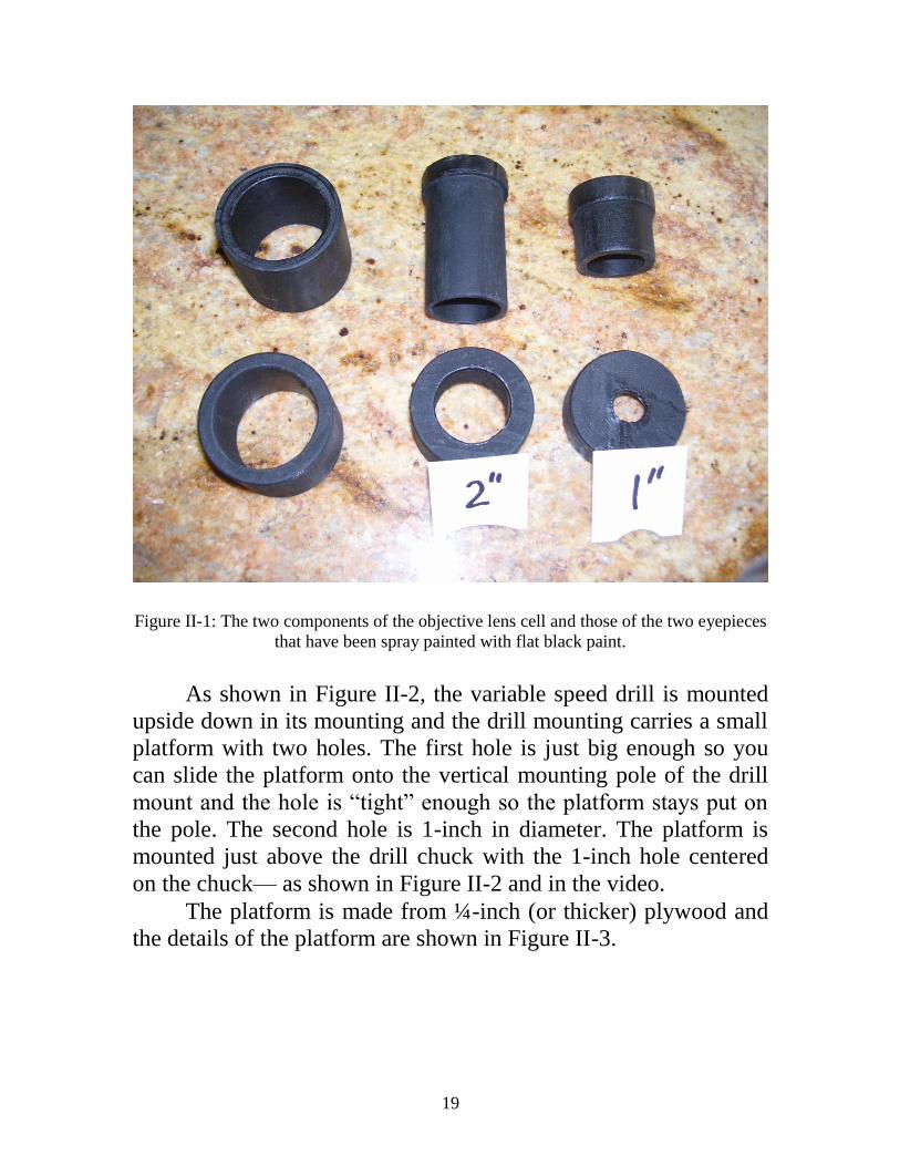
Figure II-1: The two components of the objective lens cell and those of the two eyepieces
that have been spray painted with flat black paint.
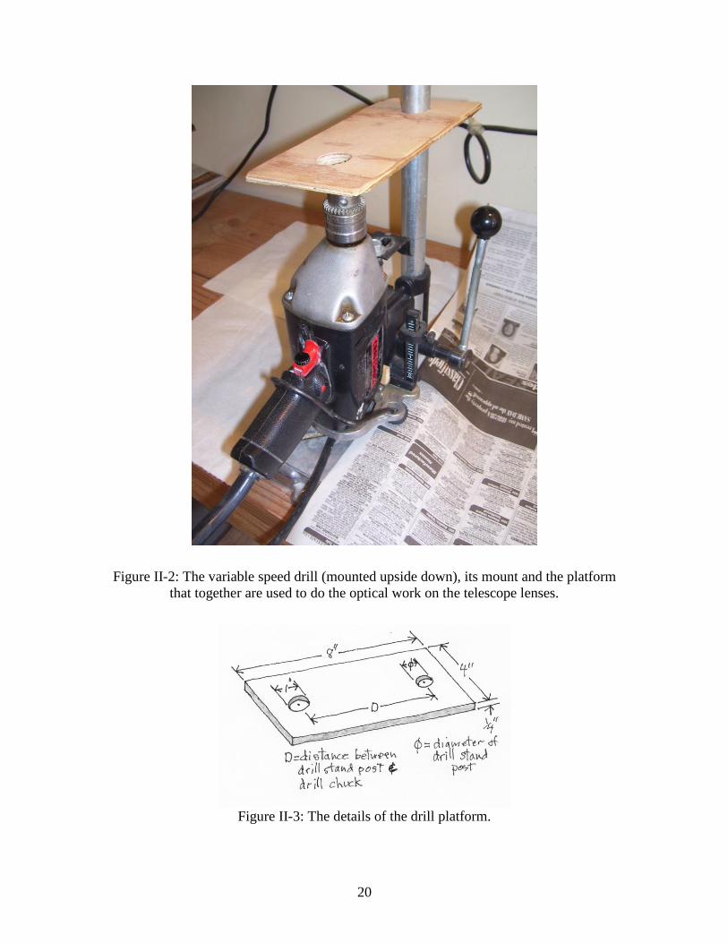
As shown in Figure II-2, the variable speed drill is mounted
upside down in its mounting and the drill mounting carries a small
platform with two holes. The first hole is just big enough so you
can slide the platform onto the vertical mounting pole of the drill
mount and the hole is “tight” enough so the platform stays put on
the pole. The second hole is 1-inch in diameter. The platform is
mounted just above the drill chuck with the 1-inch hole centered
on the chuck— as shown in Figure II-2 and in the video.
The platform is made from ¼-inch (or thicker) plywood and
the details of the platform are shown in Figure II-3.
20
Figure II-2: The variable speed drill (mounted upside down), its mount and the platform
that together are used to do the optical work on the telescope lenses.
Figure II-3: The details of the drill platform.

21
Figure II-4 shows the shallow, plastic tub, with a ½- to ¾-
inch hole in the bottom and a dam, made of play-dough, modeling
clay or some similar pliable material, around the hole. This tub is
located on the platform with its hole over the hole in the platform
(Figure II-5), where it will keep water, grinding grit, grinding mud
and/or polishing CeO from dropping down into the drill chuck and
spinning off the rotating spindles and glass blanks on to their
surroundings. We will call this tub the “catch tub”.
Figure II-4: The plastic “catch tub” used to catch grinding grit, mud, polishing CeO and
water from dropping onto the inverted drill.

22
Figure II-5: The placement of the catch tub on the drill platform.
Making the Objective Lens
The first tasks in making the objective lens are to fine grind
and polish its flat - or plano-side. While plate glass is flat enough
so this step is not necessary when making the plano-convex
eyepiece lenses, this is not necessarily the case for the objective
lens. So, you will need to fine grind and polish the plano-side of
the objective lens.
Before shipping the kit to you, we inspected the two, 1¾-inch
diameter plate glass blanks for the objective lens and marked one
with a T on both sides; this is the so-called “Tool” blank. The

23
blank may have scratches on both sides, but that is of no concern.
The second blank has a P on one side and a CV on the other. The
P side is to become the plano-side of the lens and will be scratch
free or only have very fine scratches that will grind out when you
are fine grinding the plano-side. The CV side will become the
convex side and may, or may not have more significant
scratches—scratches that will grind out during the grinding
processes.
Step 1 - Fine Grinding:
As shown in the video, place a piece of newspaper on a table
or counter top (Figure II-6), fill the glass or plastic bowl with
water, dip the tool (T blank) in the water, place the tool on the
newspaper, sprinkle a little #600 grit on the tool’s upper surface
(you may want to put the grits in little plastic cups to make them
easier to handle), and place the CV blank with the P side down on
the tool. Press down hard while moving the CV blank straight back
and forth by 1/3 of the diameter* of the blank, or just over ½-inch.
Each such “back-and-forth stroke” should take about a ½-second,
or so.
Figure II-6: Getting ready to start grinding the plano-side of the objective lens.

24
* Note: When grinding or polishing a lens or a mirror for a
telescope, one uses a 1/3-diameter stroke because it creates a
spherical surface, which is what you want to produce. If you use a
longer or shorter stroke, the surfaces of the lens or mirror and their
tool are no longer spherical.
Each successive stroke must be made at a different angle, so
the center of the blank makes a star pattern as shown in Figure II-7
and after several strokes (8 to 10) you should have gone once
around the star pattern. Simultaneously, while continuously
changing the direction of the stroke, you must rotate the CV blank
in your hand by about the same amount that you have rotated the
stroke direction—but in the opposite direction as in Figure II-7.
Figure II-7: Diagram showing the motions used in grinding and polishing.
Do not try to make length and direction of the strokes and
rotations of the CV blank perfectly regular. The natural
randomness of the strokes and two opposite rotations, along with
the rotations themselves, insures that the grinding is symmetric
with respect to the center of the blank.
As you are grinding, you will hear a grinding sound. As the
grit breaks down to “mud”, the grinding sound will diminish and
then it is time sprinkle more water and more #600 grit on the tool.
The time it takes to grind the grit down to mud is called a “wet”.
But—before adding more grit, wipe the mud off the CV

25
blank and inspect it. If, as expected, there are irregularities on the P
side of the CV blank, the high parts of the irregularities will be
fairly well ground while the low parts may still be polished. The
idea is to do as many such wets as are necessary to have the P
surface of the CV blank and tool uniformly ground, so all the
irregularities are ground flat.
Now, the grinding process described above causes the upper
blank (the P side of the CV blank) to become very slightly concave
and the top of the tool to become very slightly convex. While this
is how the curves for lenses and mirrors are generated, we do not
want this to happen for the plano-side, since it must be flat. So,
every minute or so, you must reverse the position of the tool and
the CV blank on the newspaper and in your hand. As long as you
spend about the same amount of time grinding with the tool on
bottom of the CV blank as well as on the top, the P side of the CV
blank will be essentially flat.
The fine grinding of the plano-side of the CV blank should
take just a few minutes, but may take a longer. When the P side of
the CV blank and the tool are uniformly ground, you are ready to
polish the plano-side of your objective lens.
Step 2 – Making the Pitch Lap:
In order to polish the plano-side of the CV blank, you must
attach the tool and the CV blank (which we will simply call the
lens from this point on) to their spindles [Note: all the remaining
optical work will be done using the spindles and the inverted drill]
and make a pitch lap.
But first, completely wash off all the grit and mud from the
tool and lens using the toothbrush. Throw the wet and “muddy”
newspaper way and put a clean piece of newspaper on the work
surface. Be absolutely sure to clean everything that could come in
contact with the tool and lens or you might end up with scratches
on your polished lens.
As shown in the video, put the optical pitch into a small
saucepan and very slowly and at low heat, melt the pitch (which is

26
very sticky). Be sure to stir the melting pitch with a wooden stick
as the pitch is melting and do not let the pitch boil. Boiling causes
the pitch to become too hard when solidified and this will cause
scratches and irregularities on the optical surfaces of the lens.
When all the pitch has completely melted, remove the
saucepan from the heat and set it on the newspaper. Take one of
the two, 1¾-inch diameter spindles, dip its wooden surface in the
melted pitch just deep enough to cover the raised ring on the outer
edge of the wooden disk. Press the finely ground side of the tool on
the pitch on the raised rim of the wooden disk of the spindle,
making sure the tool is centered on the spindle’s central hole and
is not tilted.
If the tool is not centered or tilted and the pitch has hardened
so the tool will not move, heat the tool and pitch under hot running
water until the pitch softens and you can then center the tool and/or
remove its tilt.
Next dip the second spindle in the hot pitch, but again, just
deep enough to cover the raised ring on the outer edge of the
spindle’s wooden surface and stick the lens to the spindle—but in
this case, stick the CV side (the still polished side) of the lens to the
spindle—leaving the finely ground plano-side free and making
sure it is centered and not tilted.
Now, once the pitch has cooled, use a single edged razor to
trim off the pitch that has oozed out from the space between the
glass blanks and the wooden spindle.
Pour ¼-inch to ½-inch of water in a small, wide mouth jar or
tub and pour the CeO polishing powder in the water. Stir the
mixture of water and CeO with the plastic spoon until all the CeO
is suspended in the water to make a slurry. Put the lid on the jar or
tub and keep it on except when the CeO slurry is being used.
Cut a 6- to 7-inch long, ¾-inch wide strip from a piece of
newspaper and rap it around the tool and the top of its spindle and
fasten it with a little masking tape—thereby making a dam ¼-inch
tall around the top of the tool (see video).
Put the bolt of the spindle holding the tool, with the paper

27
dam, through the holes in the plastic tub and platform and into the
inverted drill’s chuck. Tighten the chuck, making sure that the top
of the tool is horizontal (see the video and Figure II-8). Take the
saucepan with the pitch (the pitch should still be melted—if not,
re-melt it) and pour the melted pitch onto the tool’s surface until
the pitch completely fills the dammed space to the point where the
pitch bulges a little bit over the paper dam, but not so full that the
pitch runs over the dam.
Let the pitch cool to the point where it is no longer a thick
fluid, but is still a little soft — this may take several minutes. As
long as the pitch has a shiny surface, it is still too fluid to proceed.
As the pitch cools, the edges will start to take on a dull luster.
When the entire surface is slightly dull, you can proceed.
Now comes the difficult part, getting contact between the
pitch lap and the finely ground surface of the lens.
Stir the CeO slurry in the bottle and spoon a little of the CeO
slurry on the surface of lens, coating its entire surface with slurry.
As shown in the video, holding the lens/spindle by the lens (not by
the bolt), gently place the finely ground face of the lens on top of
the pitch and slowly move the lens/spindle around using the same
stroke/rotation combination used in the fine grinding.
Figure II-8: Getting ready to make the pitch lap.
28
If the pitch is still too hot and soft, it will ooze out over the paper
dam. In this case, stop moving the lens, leave the lens exactly
centered on top of the pitch lap (or just lap from this point on) and
let the pitch cool a little longer.
If, or when, the pitch has just about the right hardness, you
will be able to press harder and harder on the lens and the pitch’s
surface will very slowly yield and make better and better contact
with the finely ground surface of the lens. Keep moving the lens
around on the forming lap and pressing down moderately hard,
until the pitch has completely hardened. Slide the lens off the lap
and you will see the pitch has a dull, flat surface out to its edge.
However, if the outer most edge of the lap is shiny, you do
not have contact all the way to the edge and/or if the surface of the
lap is irregular or has bubbles that form shallow holes in the lap,
remove the lap/spindle from the chuck, warm the lap and the lens
under hot, running water a few minute to soften the pitch. As
shown in the video, you can work the lap and lens together, by
hand, by pressing the lens down onto the lap and continue moving
and pressing the lens down on the lap until contact is achieved
under the hot running water. You may need to add CeO slurry to
keep the lens from sticking to the lap. Repeat this procedure until
you have good contact between the lens and the lap.
Slide the lens off the lap. If, as is probably the case, the pitch
has oozed over the edge of the paper dam and the dull, flat surface
of the lap extends beyond the edge of the glass tool, you need to
trim the lap. Take the masking tape off the paper dam, wet the
paper and remove as much of the paper dam as possible without
disturbing the pitch. Then, harden the lap by putting it in crushed
ice and water for a few minutes. Using a single edge razor, trim the
excess pitch off the edge of the lap (see the video) until the lap’s
diameter is the same as the glass tool, i.e., 1¾-inchs in diameter.
Using a single edge razor, cut two channels (following the
pattern in Figure II-9)—about 1/8 of an inch wide and nearly that
deep in the surface of the lap (see video).

29
Figure II-9: The pattern of the channels you are to cut in the lap.
Take note of the fact that, as you are trimming the lap and
cutting the channels, the pitch you are trying to cut off may chip
off, rather than be smoothly cut off. Regardless, the pitch chips
tend to stick to you fingers, the surface of the lap and anything else
they come in contact with. You can trim the lap and cut the
channels “out-of-doors” and let the chips fall where they may, or
do the trimming and channeling under running, ice cold water. In
either case, when you are finished trimming and channeling, wash
your fingers and the lap in cold water—this will remove most of
the annoying pitch chips. If that fails, wipe your fingers and
anything else with pitch chips stuck to it, but not the surface of the
lap, with a paper towel that is moistened with a little turpentine.
Please Note: Making a good lap, getting good contact
between the lap and the lens, trimming and channeling a lap takes
practice and getting the feel of how pitch reacts. You may not get it
right the first or even second try, so don’t worry about having to
remake the lap.
Step 3 – Polishing the Plano-Side of the Lens:
Warm the newly made lap by running very warm water over
it and the lens for a few minutes and put the lap/spindle back in the
chuck. Stir the CeO slurry. Spoon some of the CeO slurry on the
warm lap and, holding the warm lens/spindle at the edges of the
lens (see video), press the lens down on the lap with a modest
amount of pressure and, using the same ½-inch stroke and rotation
of the lens you used during fine grinding, start polishing the plano-
side of the lens by hand. Doing this for 20 or 30 seconds will help

30
get good contact. Then turn on the variable speed drill with a spin
rate a few revolutions/second* and continue polishing. As the CeO
slurry either begins to get dry or as the slurry is used up, add more
slurry.
* Note: There is a tradeoff between spin rate, how fast the
grinding or polishing goes and your ability to control the motion of
the lens or lap during the grinding or polishing. The faster the spin
rate, the faster the grinding and polishing will go, i.e., the less time
it will take do the grinding and polishing. However, as the spin
rate gets higher and higher, there is a rate above which you cannot
control the motion of the tool, lap or lens you are holding in you
hand while trying to use the required stroke (e.g., Figure II-7) to do
the grinding and polishing, i.e., you cannot keep the tool, lap or
lens on its spinning counterpart. This problem is made worse if the
tool, lap or lens on the spinning spindle is not well centered and is
tilted. You will have to find, via trial and error, the best spin rate
to use while making the lenses for your telescope.
Stop polishing after about 10 to 15 minutes, remove the
lap/spindle from the chuck and put the lens/spindle in its place.
Just as you did during fine grinding, you need to reverse the
positions of the lap and lens every 10 to 15 minutes to insure the
plano-side is flat.
But, before you put the lens/spindle in the chuck and proceed
with polishing, wipe the CeO slurry from the lens using the side of
you arm (see the video, assuming your arm is clean and not
sweaty) and inspect the lens by looking at the reflection of a light
bulb from the lenses surface. You will see that the lens has begun
to polish, though the polishing might not be totally uniform, i.e., it
may be polished more at the center or along the edge. This is OK
now, but, if this condition persists after 30 or 40 minutes of
polishing, you need to reheat the lap and lens under hot running
water and get better contact between the lens and the lap, as
described in the section on making the lap, before continuing.
Assuming that (as will often be the case) the lens is polishing
fairly uniformly after your first 10 to 15 minutes of polishing and
31
your first inspection, put the lens/spindle in the drill chuck and do
another 10 to 15 minutes of polishing with the lap on top of the
lens, adding CeO slurry when necessary and using the same ½-inch
stroke and rotation. Continue polishing this way—reversing the
positions of the lap and lens every 10 to 15 minutes and inspecting
the polish of the lens.
It will take from 1½ to 3 hours (depending on how fast the
spindle is rotating) to completely polish the plano-side of the lens.
However, since polishing is a little tedious, you will probably want
to break up your polishing work into 15- to 20-minute sessions.
Also, as you are polishing, the two channels you cut into the lap’s
surface may partially close because of the heat generated by
polishing. When you see that the channels have partially closed,
you will need to reopen them with the single edge razor. Finally,
after you have had a break and/or reopened the channels and want
to start polishing again, remember to warm the lap and lens under
running warm, water before starting each 15- or 20-minute
polishing session.
After about an hour or so of polishing, the plano-side may
look completely polished to the naked eye, but if you use a hand
lens or magnifying glass to look at the surface in reflected sun- or
lamp- light you will see that the surface has numerous fine pits.
Keep polishing until the pits are gone.
Also, though ideally the polishing should be uniform over the
plano-surface of the lens, our experience is that this is not always
the case. If, as stated above, the lens is polishing well at the center,
but not on the edge, or visa versa, and this persists even after
getting good contact between the lap and lens - and after polishing
for an hour or so, you will have to do one of the following:
A) If the lens is polishing well at the center but not at the
edge, use a ¾-inch or even a 1-inch stroke and/or have
the stroke go over the lens towards the edge of the lens
rather that over its center (see video), i.e., concentrate the
polishing at the edge of the lens.
B) If the lens is polishing well at the edge but not at the

32
center, put the lap/spindle in the drill chuck and continue
polishing with the lens on top and the lap on the bottom.
Use a ¾-inch or even a 1-inch stroke, but have the stroke
go over the lens’ center (see video), i.e., concentrate the
polishing at the center of the lens.
Once the plano-side of the lens is completely polished, you need to
remove the lens from its spindle and stick it back on the spindle
with the newly polished plano-side stuck to the wooden ring on the
spindle, with the CV side free. You must also remove the lap from
the tool before you proceed.
Figure II-10: Removing the lens from the spindle is made simple by setting the
lens/spindle in a bowl of crushed ice for several minutes.
The easiest way to remove the lens and tool from their
spindles and getting the lap off the tool is to set the lens and the lap
and its tool in a bowl of crushed ice (Figure II-10 and the video).
Because of the differences in the thermal contraction of the glass
of the tool and lens and that of pitch, the lenses and lap will
become unstuck in several minutes. The lens/tool/lap will slide
apart, usually with a little force, but if they don’t, you will either
have to wait for them to get colder on the ice and/or push harder. If
that does not work, strike the glass lens or tool with a heavy

33
wooden stick.
Once the lens is off its spindle, re-melt the pitch in the
saucepan, dip the spindle in the pitch as described earlier and
stick* the newly polished, plano-side of the lens to the spindle,
with the CV side free—being sure the lens is centered on the
spindle and not tilted. Then put the lens/spindle back in the chuck
of the inverted drill and tighten the chuck.
* Note: Or, as shown in the video, just hold the pitched side
of the spindle over the source of heat and re-melt the pitch on the
spindle and then stick the newly polished, plano-side of the lens to
the spindle, with the CV side free. Also, as often happens during
grinding and/or polishing, the tool/lap or lens may come off its
spindle. If so, heat the pitch on the spindle and stick the tool/lap or
lens back on its spindle.
It is possible, that, due to the ice, the lap may also have
become unstuck from the tool. If the lap does slide off the tool, put
the lap back in the saucepan, since the pitch of the lap can be re-
melted with the rest of the pitch in the pan.
If the lap does not come free from the tool, lay it down on a
piece of newspaper and use a single edge razor to cut and chip the
lap off the tool. As above, put the chunks of pitch back in the
saucepan for re-melting. Wipe the surface of the tool with a paper
towel moistened with turpentine to clean off any remaining pitch
stuck to the tool’s surface.
Step 4 – Grinding the Convex Side of the Lens:
Step 4a – Rough Grinding with #220 Grit:
Because the shallowness of the convex curve needed to make
the objective lens with a 60-inch focal length is so slight (0.012-
inches), rough grinding is done using #220 grit.
Put the lens/spindle in the chuck of the inverted, variable
speed drill and tighten the chuck. Turn the variable speed drill on
with a spin rate of a few revolutions/second. Put a newspaper down
next to the inverted drill and its mount. Set the bag of #220 grit and
a small bowel of water on the newspaper.

34
As shown in the video, sprinkle some water on the slowly
spinning lens and then sprinkle some #220 grit on the lens. Hold
the tool/spindle by the wood of the spindle, press the tool down
hard on the lens and – in principle – use the 1/3 diameter- or just
over ½-inch- stroke, to start grinding, while frequently rotation the
lens the way you did while fine grinding and polishing the plano-
side of the lens.
We say “in principle” use the 1/3 diameter stroke, because
that will give you a spherical surface. However, when roughing out
the curve one can use several different methods to save time and
effort (e.g., see the section on rough grinding the strongly curved
eyepiece lenses below). In the case of the objective lens with its
very shallow curve, you could use the 1/3 diameter stroke and
generate the desired curve in about an hour and in the process
grind off nearly 1/16th
of an inch of the thickness of the lens blank!
To reduce the time required to do the rough grinding, you should
use a ¾-inch or even a 1-inch stroke for the first 15 to 20 minutes
of rough grinding. Then return to using the 1/3 diameter or about a
½-inch stroke for the rest of the rough grinding to get the lens’
surface spherical.
As you start rough grinding, the #220 grit will quickly grind
down to mud. When it does, leave the mud on the lens and tool and
add more water and grit and keep grinding.
After 10 minutes of rough grinding, stop and wash off all the
mud from the tool. As shown in the video, make a focus tester
from a yardstick with a piece of stiff, white paper taped vertically
to the end of the yardstick as a focus target. As in Figure II-11 and
the video, go out doors (assuming it is during the day) and point
the yardstick towards the Sun, with the end with the paper target
pointing towards the Sun. Wet the tool’s surface and hold the tool
on the yardstick about 30 inches from the end with the paper
target. Move the yardstick and/or tool around until the reflection of
the Sun off the wet surface of the tool is on the paper target. Since
the tool is slightly concave, it will form a very rough image of the
Sun on the target. Move the tool closer and closer to the target. If

35
the rough image of the Sun gets smaller, move the tool even closer
until the blurry image starts to get sharper and then starts to get
bigger and blurry again. Go back and forth until you find the
distance from the tool to the target where the Sun’s image is the
sharpest and smallest—that will be the tool’s focal length.
Figure II-11: Measuring the focal length of the tool.
Alternatively, if the image of the Sun gets bigger when you
first move the tool closed to the target, move the tool farther from
the target and keep moving it farther and farther until you have
found the distance from the tool to the target where the Sun’s
image is smallest and sharpest—that will again be the focal length
of the concave tool.
Three points: First, the concave tool will dry off quickly
during this testing, so you will have to keep wetting it.
Second, the determination of the focal length of the concave
tool will be quite inaccurate at this stage—there will be at least a

36
few of inches of uncertainty.
Third, the focal length of the convex lens itself will be nearly
4 times the focal length of the tool. For example, if the first rough
check of the focal length of the tool is 25 inches, then the focal
length of the lens is about 96 inches.
The goal of the rough grinding is to get the focal length of the
lens to be about 75 inches, so you need to keep rough grinding
until the tool’s focal length is about 20 to 22 inches. It should take
20 to 40 minutes of rough grinding to get the focal length of the
tool in this range.
If you over shoot and the focal length of the tool is less than
about 20 to 22 inches, put the tool/spindle in the drill chuck and
grind with the lens/spindle on top until tool’s focal length is about
20 to 22 inches. When you have reached that point, you are done
with rough grinding.
A word of warning – in the case of the long focal lens you are
making, just a few minutes of grinding will change the focal length
of the tool by inches. So, as you are getting close to the desired 20-
to 22-inch focal length of the tool, stop and test the focal length
every few minutes and keep track of the time spent and focal
length of the tool in your log book.
When the tool has about a 20- to 22-inch focal length, you
are ready to start fine grinding.
Step 4b – Fine Grinding with #400 Grit:
Take the lens/spindle out of the chuck, take the catch tub off
the platform and carefully clean all the grit and mud off them and
also off the tool/spindle under running water, using the old
toothbrush. Wipe off the platform and chuck with a moist paper
towel. Close the bag of #220 grit and put it away, wash out the
water bowel and throw the old newspaper way.
Put the catch tub back on the platform, put the lens/spindle
back in the chuck and tighten it, put a clean newspaper next to the
drill and mount. Put the little bag of #400 grit and the bowel with
clean water on the newspaper.

37
Start the drill at the same spin rate, sprinkle some water and
#400 grit on the lens and start the fine grinding, using the same 1/3
diameter stroke and lens rotation motion as before. Add new grit
and water as necessary. Test the focal length of the tool every five
minutes or so using the Sun and the yardstick/paper target. Your
goal is to get the focus of the tool down to 18- to 19-inches.
15 minutes of fine grinding with #400 grit will remove all the
pits generated by rough grinding with #220 and the focal length of
the tool should be close to the desired 18 to 19 inches. If not,
continue grinding with #400 grit with the tool on top if the focal
length is longer than about 18- to 19-inches or with the lens on top
if the focal length is less than about 18- to 19-inches, until the
focal length of the tool is 18- to 19-inches.
Step 4c – Fine Grinding with #600 Grit:
Repeat all the steps under Step 4b, except use #600 grit and
get the tool’s focal length to be 16- to 17-inches. If not, continue
grinding with #600 grit with the tool on top if the focal length is
longer than 16- to 17-inches or with the lens on top if the focal
length is much less than about 16- to 17- inches, until you get the
focal length of the tool to be 16- to 17-inches. Now you have a
finely ground, slightly convex lens surface ready for polishing.
One final note: due to the inaccuracies in measuring the focal
length of the tool and hence that of the lens during rough and fine
grinding, the focal length of the lens, when fully polished may be
up to several inches longer or shorter that the desired 60 inches.
We will comment more on this towards the end of the following
section.
Step 5 – Polishing the Convex Side of the Lens:
As in the above steps, wash and clean all the surfaces, the
lens- and tool/spindles and the catch tub.
Then follow the instructions given in “Step 2 – Making the
Pitch Lap”, starting with the paragraph that begins with “Cut a 6-
to 7-inch long, ¾-inch ….“ given above—with the one exception.

38
When pouring the melted pitch on the top of the tool to fill the
space formed by the paper dam and the top of the tool, fill that
space only up to the top of the paper dam. Do not fill it to the point
where the pitch bulges a little bit over the dam. When you press the
lens (covered with CeO slurry) down on the warm pitch, the
convex surface of lens will first come in contact with the pitch’s
surface in the middle and, as you continue to push down and move
the lens around, the contact surface will slowly spread out towards
the edges of the lap and lens. In doing so, the pitch will bulge over
the edge of the dam by itself. Other than that, follow the instruction
given in that section and when the lap is cooled, trimmed,
channeled and has good contact, you are ready to polish the convex
surface of the lens.
Polishing the convex side is done in the same way as the
plano-side was polished—as described in “Step 3 – Polishing the
Plano-Side of the Lens”—except, keep the lap on top and the lens
on the bottom during all the polishing - unless the lens is not
polishing uniformly. If so, follow the instructions in that section to
correct the situation.
Now, after you have polished for 10 to 15 minutes, you will
see that the surface is beginning to polish. In fact, after only 10 to
15 minutes, the polish is good enough so you can accurately
measure the focal length of the lens using the Sun. If you choose
to, you can remove the lens from its spindle – or if and when the
lens comes free itself and before you re-pitch it to its spindle - you
can clean the CeO off the lens and measure its focal length. Use
the Sun or the nearly full Moon, a stiff, white paper target, and a
carpenter’s ruler or two yardsticks taped together, to determine the
exact focal length of your slightly polished objective lens (see
video). You should be able to measure the focal length with an
accuracy of an inch or two and the focal length will probably
be within a few inches of the desired 60 inches, i.e., somewhere
between 55 and 65 inches.
If the focal length of the lens is a just a few inches longer that
60 inches, continue polishing with the lens on the bottom and the
39
lens on top – this will shorten the focal length by a couple of
inches.
If the focal length of the lens is a just a few inches shorter
that 60 inches, continue polishing with the lap on the bottom and
the lap on top – this will lengthen the focal length by a couple of
inches.
Or, if the focal length is longer than 65 inches or shorter than
55 inches – or if you just want to get the focal length closer to the
desired 60 inches - we recommend (but you do not have to do so)
that you go back to fine grinding with #600 grit. You will have to
remove the lap from the tool and, as during fine grinding, grind
with the tool over the lens to shorten the focal length or grind with
the lens over the tool to lengthen the focal length of the lens.
Remember that a few minutes of grinding, even with #600 grit,
will change the focal length by inches – so test the focal length of
the tool every few minutes. When you have gotten the focal length
of the tool to the desired 16- to 17-inches, you are ready to make a
new lap and start polishing again.
Completely polishing the lens should take 1½ to 3 hours.
When the lens is completely polished, remove it from its spindle
using the crushed ice method as described earlier. Clean the CeO
off the lens under running water and, if any pitch it stuck to the
lens, remove it with a paper towel moistened with turpentine. Then
wash the turpentine off. You can use Windex and a soft cotton
handkerchief to give the lens its final cleaning.
Again, using the Sun or the nearly full Moon, a stiff, white
paper target, and a carpenter’s ruler or two yardsticks taped
together, determine the exact focal length of your newly finished
objective lens. You should be able to measure the focal length with
an accuracy of about ½ of an inch and the focal length of the lens
will probably be within a few inches of the desired 60 inches, or at
least somewhere between 55 and 65 inches. Do not be concerned if
the focal length is not exactly 60 inches, you just need to know
what the focal length is to be able to make the telescope tube the
correct length.

40
Finally, though you will want to have your lens completely
free from scratches and pits, if there is a small scratch or two or a
few pits on the objective lens, they will not affect the performance
of your telescope.
Regardless, you now have a beautiful objective lens of your
own making. So, we congratulate you.
Making the 2-inch and 1-inch Focal length Eyepiece Lens
Grinding and polishing the eyepiece lenses are done in
essentially the same way you did for the convex objective lens.
The differences are described in the following.
First, as indicated in the first paragraph in the section on
“Making the Objective Lens”, the surfaces of the plate glass blanks
are flat enough so you do not need to grind and polish their plano-
sides as you did for the objective lens.
Second, we have marked the 11/4-inch diameter and the ¾-
inch diameter blanks that are to be used for the tools with a T. We
have marked the 11/4-inch diameter and the ¾-inch diameter blanks
that are to be used for the lenses with a CV on the sides to be
ground and polished and P for the sides that will be the plano-sides
and that are free from scratches.
Third, as seen by the curves of the templates for the convex
sides of the lenses, the convex sides of both eyepiece lenses are
very strongly curved, i.e., you have to grind off a lot of glass
during rough grinding to make these eyepiece lenses. So rough
grinding will be done with #80 grit and fine grinding will be done
with #220, #400 and #600 grits.
Fourth, since the curves on the convex sides of the eyepiece
lenses are so strongly curved, the stroke you will use during the
rough grinding is different from that used while making the
objective lens and that you will use during the fine grinding stages
and polishing of the lenses. Previously, you mainly used a 1/3-
diameter stroke, going back and forth over the center of the lens,
tool, or lap, while rotating the lap, tool or lens in your hand and, as

41
noted above, that stroke produces the desired spherical surface on
the lens. However, if you use a 1/3-diameter stroke going back and
forth over the center of the lens during rough grinding when the
desired convex curve is very strongly curved, it will take a long
time to reach the required curvature and the lens will become too
thin. To avoid these problems, start rough grinding using the 1/3-
diameter stroke while rotating the tool in your hand, but the stroke
should not go over the center of the lens—rather it should pass
nearly over the edge of the lens – i.e., as close to the edge as
possible (Figure II-12a). As discussed in more detail below,
towards the end of rough grinding, the center of the stroke must
pass closer and closer to the center of the lens (Figure II-12b), until
at the end of rough grinding, the stroke passes over the center of
the lens (Figure II-12c). This will insure that the rough ground
surface of the convex lens is spherical.
Figure II-12: (a) Diagram of the movement of the center of the tool over the lens used
during most of rough grinding the eyepiece lenses; (b) Diagram of the movement of the
center of the tool over the lens used towards the end of the rough grinding of the eyepiece
lenses; (c) Diagram of the movement of the center of the tool over the lens used at the
end of rough grinding the eyepiece lenses.
Fifth, because of the force applied during, especially, rough
grinding, the lens (and possibly tool) will most probably come
loose from its spindle. When this happens, take the spindle out of
the drill chuck, wash all the grit and mud or CeO from the lens and
spindle, hold the pitched side of the spindle over the hot heating

42
element until the pitch has melted and then re-stick the lens (or
tool) to the spindle.
Finally, since each lens will go through the same grinding
and polishing steps, you can save time and effort cleaning up
everything between each grade of grit or before making the laps
and polishing, by doing each step on both lenses before going to
the next step, e.g. first rough grind the 11/4-inch diameter lens with
#80 grit and then rough grind the 3/4-inch diameter with #80 grit
before cleaning up and start fine grinding with #220 grit. Then do
the fine grinding with #220 grit on both lenses, clean up everything
and then go on to #400 grit, and then #600.
Step 1 - Sticking the Blanks to their Spindles:
As you did while making the objective lens, melt the pitch in
the saucepan, dip a 11/4-inch diameter spindle in the melted pitch
just deep enough to cover the raised wooden ring on the spindle
and stick the 11/4-inch diameter tool (T) blank to it. Be sure the
blank is exactly centered on the spindle and that it is not tilted. Do
the same for the 11/4-inch diameter lens blank with the P side stuck
to the spindle and the CV side free. Repeat these steps for the 3/4-
inch diameter tool (T) and lens (CV, P) blanks and their spindles.
Step 2 – Rough Grinding:
Put the catch tub on the platform, put the 11/4-inch diameter
lens/spindle in the drill chuck, tighten the chuck and start the drill
turning at a few revolutions/second.
Spread a clean newspaper out next to the inverted drill and its
mount, place the water bowl and the bag of #80 grit on the
newspaper, sprinkle some water and #80 grit near the edge of the
rotating lens and, holding the tool/spindle by the tool blank, start
rough grinding while pressing down with a lot of pressure.
As discussed on the previous page, use a 1/3-diameter stroke,
which in the case of the 11/4-inch diameter lens is a little less than a
1/2-inch stroke—with the stroke centered very, very near, the edge
of the lens (see video)—and press the tool down very hard on the

43
lens. Also, for the first several wets you should slightly tilt the tool
so only the center of the tool is in contact with the edge of the lens.
This will help start grinding off the edge of the lens. After a few
wets, the tool will naturally tilt this way as you keep the stroke
passing over the edge of the lens.
After 15 to 20 minutes, i.e., after many wets of fresh #80 grit
and water, stop the drill, wipe off the mud from the tool and lens
and inspect both of them. A shallow depression will have formed
at the center of the tool and the edges of the lens will have been
somewhat ground off. Grind another 15 to 20 minutes, keeping the
center of the tool very near the edge of the lens as shown in the
video, and check the lens and tool again. The central hole in the
tool will be deeper and wider and the edges of the lens will be
ground off further. As you proceed in this way the concave
depression in the tool will have become deeper and wider—and the
ground part of the edge of the lens will have deepened and
widened. After about 1 hour of grinding the 2-inch focal length
lens (and ½ of an hour for the 1-inch focal length lens), you can
use the template to determine how close you are to having the
correct curvature of the lens. The lens may still have a flat, un-
ground spot at its center and the tool may still have un-ground
edges. Continue grinding and testing this way, until A) the concave
depression has reached the edge of the tool, B) the convex surface
of the lens extends all the way across the lens so there is no flat,
partly reflective spot in the middle of the lens and C) the curve of
the lens exactly fits the template, as in Figure II-13. Rough
grinding to this point will probably take less than 2 hours for the 2-
inch focal length lens and less than an 1 hour for the 1-inch focal
length lens.
Also, during rough grinding of eyepiece lens, a lot of the
fresh #80 grit will fall off the lens and collect in the catch tub along
with the mud. Since rough grinding of the eyepiece lenses takes a
lot of #80 grit, you can periodically scoop up some of this grit and
dump it back on the lens rather than always adding fresh grit from
the bag of #80 grit (but don’t bother to do this for the finer grits).

44
In addition, you can minimize the amount of fresh grit that
fall off the lens into the catch tub after the tool begins to be
concave during rough grinding with #80 grit (and later during the
fine grinding stages) as follows. Hold the tool with the concave
side up and sprinkle the fresh grit on the wet surface of the
concave tool.
Now, to make sure the curves of the lens and tool are
spherical, grind another 15 or 20 minutes as you move the center
of the stroke closer and closer to the center of the lens, as shown in
Figure II-12a and b. Check to insure that the curve of the lens
exactly fits the template, as in Figure II-13.
At this point you are finished rough grinding the 11/4-inch
diameter lens and its radius of curvature is that required for the
correct focal length, i.e., the template fits it.
Do not bother to clean up, just take the 11/4-inch diameter
lens/spindle out of the chuck of the drill and replace it with the ¾-
inch diameter lens blank/spindle. Then, using the ¾-inch tool
blank/spindle and the #80 grit, start rough grinding the ¾-inch lens
in exactly the same way as you did the 11/4-inch diameter lens—
using a 1/3-diameter stroke (1/4 of an inch) near the lens’ edge and
the ¾-inch template to test the curvature of the ¾-inch diameter
lens.
When you have finished rough grinding the ¾-inch diameter
lens, clean both lens/spindles, both tool/spindles, the catch tub, etc.
and get set up with clean newspaper, #120 grit and clean water for
fine grinding.
Steps 3, 4, and 5 - Fine Grinding with #220, #400 and #600 grits:
Proceed with fine grinding with the three grades of grit of
both lenses in exactly the same way you did the convex side of the
objective lens, cleaning up properly between each successive grade
of grit and use the 1/3-diameter stroke over the center of the lens
while rotating the tool/spindle in you hand as the lens rotates at a
few revolutions/second on the inverted drill. You must spend a
minimum of 15 minutes of fine grinding with each grade of grit for

45
each lens.
As you are fine grinding with each grade of grit, you should
check the curvature of the lenses with its template once or twice to
see if you have excellent contact between the convex surface of the
lenses and its template, as in Figure II-14. When you finish fine
grinding, you must have excellent contact between the lenses
convex surfaces and their tool, as shown in Figure II-13—if you
do, the focal lengths of the lenses will be very close to the desired 2
inches and 1 inch.
Figure II-13: Diagrams that show the contact between the template and the convex side of
an eyepiece lens at the end of each stage of fine grinding.
When you have fine ground the lenses with each grade of grit
for at least 15 minutes—if you have excellent contact between the
lenses and templates, clean everything up as usual and prepare to
go to the next stage of grit.
Though very unlikely, if for any grade of grinding, the
curvature of the convex side of the lens becomes too steep, i.e.,
you only have contact between the lens and its template at their
centers (Figure II-14), put the tool/spindle in the drill chuck and,
holding the lens spindle in you hand, grind with that grade of grit
until you again have achieved contact.
46
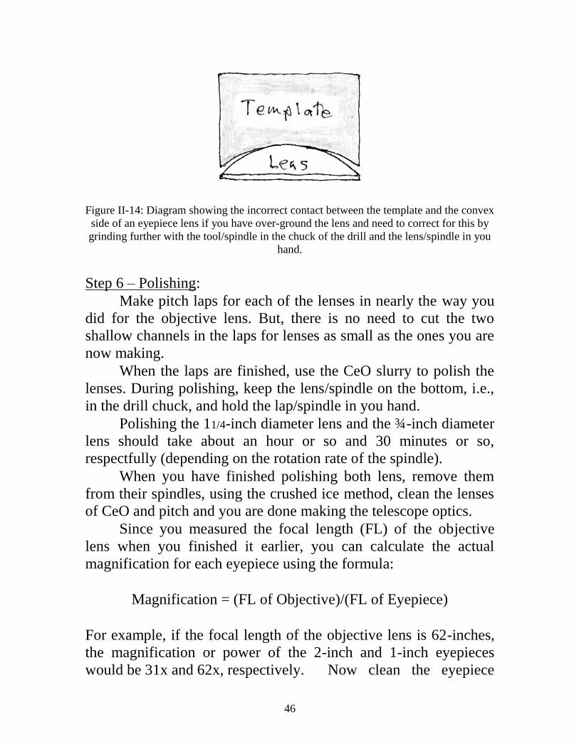
Figure II-14: Diagram showing the incorrect contact between the template and the convex
side of an eyepiece lens if you have over-ground the lens and need to correct for this by
grinding further with the tool/spindle in the chuck of the drill and the lens/spindle in you
hand.
Step 6 – Polishing:
Make pitch laps for each of the lenses in nearly the way you
did for the objective lens. But, there is no need to cut the two
shallow channels in the laps for lenses as small as the ones you are
now making.
When the laps are finished, use the CeO slurry to polish the
lenses. During polishing, keep the lens/spindle on the bottom, i.e.,
in the drill chuck, and hold the lap/spindle in you hand.
Polishing the 11/4-inch diameter lens and the ¾-inch diameter
lens should take about an hour or so and 30 minutes or so,
respectfully (depending on the rotation rate of the spindle).
When you have finished polishing both lens, remove them
from their spindles, using the crushed ice method, clean the lenses
of CeO and pitch and you are done making the telescope optics.
Since you measured the focal length (FL) of the objective
lens when you finished it earlier, you can calculate the actual
magnification for each eyepiece using the formula:
Magnification = (FL of Objective)/(FL of Eyepiece)
For example, if the focal length of the objective lens is 62-inches,
the magnification or power of the 2-inch and 1-inch eyepieces
would be 31x and 62x, respectively. Now clean the eyepiece

47
lenses they way you clean the objective lens.
Congratulation, you now have three beautiful lenses you have
make yourself. The hardest part of your journey is behind you and
you are ready to assemble your telescope.

48
Part III: Making the Telescope
Telescope Tube Materials
Assuming the focal length of your objective lens is between
55- and 65-inches long (if not, email one of us for instructions),
you will need to buy the following materials to make the telescope
tube:
1) One, 2-inch ID (Inside Diameter), 36-inch long*
mailing tube**,
2) Two, 2-inch ID, 30-inch long*** mailing tubes**,
3) One, 2-inch ID, 18-inch long**** mailing tube**,
4) One, 1½-inch OD (Outside Diameter), 12-inch long,
Flanged Tailpiece, plastic tube (Lasco brand,
from, e.g., Ace Hardware Store),
5) A can of clear Krylon spray paint,
6) Scotch Tape,
7) Cotton balls,
8) 6- to 8-inch long stick of wood.
9) Elmer’s glue and
10) Black construction paper.
* Actual length is 37 inches.
** You can buy the tubes from the Post Office, a UPS Store or a
Staples store.
*** Actual length is 31 inches.
**** Actual length is 19 inches.
Getting Ready
Before you handle the optics in preparation for the final
assembly, wash your hands to remove all the oils from your skin,
oils that could leave smudges on your lenses. Then, again,
carefully clean the three lenses with Windex and a soft, clean,
cotton handkerchief.

49
Assembling the Two Keplerian Eyepieces
As shown in Figure III-1 and the video, lay the eyepiece
lenses on their respective black, eyepiece barrels with their convex-
sides facing into the barrels. Then slide the eyepiece caps onto the
eyepiece barrels to keep the lenses in their places. If a cap is too
loose, tape pieces of Scotch Tape on the outside of the barrel,
where the eyepiece cap slides onto the barrel, until they fits snugly.
The barrels must fit in the caps very tightly, so there is no danger
of the lenses falling out—but not so tightly that you cannot remove
them when (or if) you want to clean the lenses.
Figure III-1: Mounting an eyepiece lens in its barrel.
A word of caution: Wood (even painted wood) swells and
shrinks as the humidity changes. So, even if the eyepiece caps fit
tightly on the barrels (with – or without Scotch Tape), as the
humidity drops, the caps may come loose and the eyepiece lenses
may fall out. To avoid this, you must put Elmer’s Glue along the
junction of the cap and the barrel (see the video). This will
eliminate the danger of the caps becoming loose and the eyepiece

50
lens falling out. But, if you ever need to take the lenses out of the
mounts, you can cut the glue with a single edge razor or exacto-
knife and pull the cap off the barrel to free the eyepieces lenses to
clean them.
Now, get the 1½-inch OD, 12-inch long, flanged tailpiece
plastic tube that will be the drawtube of your telescope. As shown
in the video, cut the flange off the end of the tube and file or use
sandpaper to smooth the cut end.
Also, as shown in the video, cut a 4½ x 10½-inch piece out
of a sheet of black construction paper and wrap the piece around a
broomstick to make a cylinder that is small enough to slide into the
plastic drawtube. Use a little Elmer’s glue to glue the black
construction paper inside the drawtube, with one end of the
construction paper tube flush with one end of the plastic drawtube.
The purpose of this black paper tube is to prevent light from
reflecting off the shiny white interior of the plastic drawtube into
the eyepieces.
Now insert each eyepiece into the end of the drawtube that is
free from the black paper. The eyepieces should fit snuggly, but
not tightly in the drawtube (see video). Again, because of the
swelling and shrinking of the wooden eyepiece barrels – and
because there may be slight differences in the IDs of the various
tubes, your eyepieces may fit too loosely or too tightly in the
drawtube. If the eyepieces are too loose, wrap some Scotch Tape
around the barrel(s) until they fit snuggly in the drawtube. If they
are too tight, use sandpaper to sand them down until they slide
snuggly into the drawtube.
Making the Telescope Tube
The 2-inch ID, cardboard tubes have white plastic caps at
each end. Save these caps and use one of them for the telescope’s
dust cap and two others for the dust caps for the two eyepieces,
when you are not using the telescope. We have made the diameter
of the wooden eye-lens caps of the eyepieces just big enough so
the white plastic caps will easily slide onto the eye-lens cap - once
you have cut out the little part of the plastic that is there so you can

51
get a grip on the cap to remove it from the mailing tube.
We have found that if the 2-inch ID, cardboard tubes used to
make the telescope tube are left in direct sunlight for long periods
of time and if the tubes get wet from dew (or rain), they will warp.
To minimize this, it is necessary to strengthen the telescope tube
by inserting a second tube (we call it the “inner-tube”) inside the
main tube (that we call the “outer-tube”), as described below.
Assuming the focal length (FL) of your objective lens is, as
expected, between 55- and 65-inches, the length of the outer-tube
(LOT) and the length of the inner-tube (LIT) are given by the
following formulas:
LOT = FL – 4-inches and
LIT = FL – 12-inches.
As demonstrated in the video, the best way to cut the tubes to
the correct lengths is to wrap a piece of paper around the tube
where it is to be cut, making sure that the ends of the paper exactly
overlap and use a piece of masking tape to secure the paper. Now,
using the edge of the paper as a guide and using an exacto-knife, a
box cutter or a single edge razor, carefully, and with only a little
force, make a shallow cut all the way around the tube, exactly
following the edge of the paper. Cut around the tube again, with a
little more force, to make the cut a little deeper. Keep cutting
around the tube, each time with a little more force and each time
making the cut deeper. After several such circuits, you will have
made a very clean cut through the tube.
Now, you will make the outer-tube of the telescope using the
two, 31-inch long, 2-inch OD tubes. We use the 61-inches focal
length (FL) objective lens made for the telescope shown in the
video and figures of this manual as the example of how to proceed.
Using the formula given above, the length of the outer-tube (LOT)
is (61 – 4) or 57-inches. Since the two 31-inch tubes have a total
length of 62-inchs, we cut 5-inches off one of the 31-inch long

52
tubes to make the “front section” of the telescope’s outer-tube.
Note that the 5-inch segment cut off the 31-inch tube may be use
as the dew cap (see below).
Next, you will make the inner-tube using the 37-inch and 19-
inch, 2-inch ID tubes. Again, using our 61-inch FL lens as the
example and the formula given above, the length of inner-tube
(LIT) is (61 – 12) or 49-inches. The 37-inch and 19-inch tubes have
a total length of 56-inches. The excess length should be cut from
the 19-inch tube, so we cut 7-inches off the 19-inch tube to make
what we call the “short segment” of the inner-tube and kept the 7-
inch segment for possible use as the dew cap (see below).
Next, as shown in the video, use an exacto-knife or a box
cutter to cut a ¾-inch wide strip from the side of both the 37-inch
long inner-tube and the short segment inner-tube, that together will
be the inner-tube of your telescope tube.
Regarding the 5- and 7-inch residual segments cut from the
tubes, as described below, either segment can be used for the “Dew
Cap” of your telescope, so called because it prevents dew from
forming on the objective on a cold, damp night—and protects the
objective from dust.
Now you are ready to start making your telescope. But first
note: Before you proceed, make absolutely sure the two parts of
the black, objective cell and the two unpainted wooden rings easily
slide into the 2-inch ID tubes. If they do not, sand or file them
down until they do easily slide into the 2-inch ID tubes. Also,
check to insure that the inner-tube sections easily slide into the
outer-tube sections before proceeding.
Make a swab from a 6- to 8-inch long wooden stick, a cotton
ball or paper towel and string or tape (see video). As shown in
Figure III-2 and the video, saturate the swab with Elmer’s glue and
swab a wide ring of glue around the inside of the front segment of
the outer-tube of the telescope – starting 2-inches down the tube
and extending as far down the tube as you can.

53
Figure III-2: Swabbing Elmer’s glue in the front end of the outer-tube section of
telescope tube.
Next, as in the video, smear Elmer’s glue on one end of the
short segment of the inner-tube. Then:
A) Hold the inner-tube segment by the end that is free from glue
and squeeze it so the cut edges are close together;
B) Hold the front segment of the telescope outer-tube in your
other hand and – being very careful not to let the glue on the
inner tube get on the inside of the outer-tube - insert the
glued end of the longitudinally cut inner-tube segment into
the front of the front segment of the telescope outer-tube as
far as you can;
C) Stop squeezing the inner-tube and let it open back up until it
and the glue on its end press against the inside of the front
section of the telescope’s outer-tube.
D) Now, and as shown in the video, rapidly push the inner-tube
all the way into the outer-tube and the quickly use the 37-
inch long inner-tube section, to push the front section inner-
tube further down towards the front of the outer-tube, until
the end of the inner-tube is 2-inches down into the end of the
outer outer-tube – but no closer to that end of the outer tube
segment.

54
E) Now, let the glue completely dry.
Similar to what is shown in Figure III-2 and the video, again
saturate the cotton ball with Elmer’s glue and swab a ring of glue
½-inch wide around the inside of the front section of the outer-tube
starting about ¼ of an inch down into the tube. Now, get the 1½-
inch long, back segment of the flat black, wooden objective cell,
that has a 1/8-inch tall, 1¾-inch ID retaining ring cut into one end
and slide the end of the wooden segment without the retaining ring
into the tube to where the Elmer’s glue is, i.e., until ¾-inch of the
cell, with the retaining ring, is sticking out of the tube, see Figure
III-3. Wait until the glue has dried.
Figure III-3: The correct position of the back segment of the objective cell in the front
end of the telescope tube, with the 1/8-inch tall, 1¾-inch ID retaining ring visible.
The Dew Cap: You can use either of the pieces of 2-inch ID
tube cut off the 31-inch tubes to make the dew cap, which should
be between 4- and 6-inches long. If both of these segments are
longer that 6-inches, cut one of them to the proper length.
Now, take the second 1½-inch long, front segment of the
objective cell and slide it part way into the dew cap tube. It should
fit snugly, but not so tight that it cannot slide further into the dew
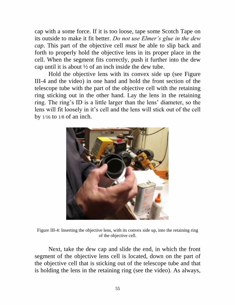
55
cap with a some force. If it is too loose, tape some Scotch Tape on
its outside to make it fit better. Do not use Elmer’s glue in the dew
cap. This part of the objective cell must be able to slip back and
forth to properly hold the objective lens in its proper place in the
cell. When the segment fits correctly, push it further into the dew
cap until it is about ½ of an inch inside the dew tube.
Hold the objective lens with its convex side up (see Figure
III-4 and the video) in one hand and hold the front section of the
telescope tube with the part of the objective cell with the retaining
ring sticking out in the other hand. Lay the lens in the retaining
ring. The ring’s ID is a little larger than the lens’ diameter, so the
lens will fit loosely in it’s cell and the lens will stick out of the cell
by 1/16 to 1/8 of an inch.
Figure III-4: Inserting the objective lens, with its convex side up, into the retaining ring
of the objective cell.
Next, take the dew cap and slide the end, in which the front
segment of the objective lens cell is located, down on the part of
the objective cell that is sticking out of the telescope tube and that
is holding the lens in the retaining ring (see the video). As always,

56
the dew cap must fit snugly so it won’t fall off, but not so tightly
that it cannot be slid down onto the objective cell. Again, if the
dew cap fits too loosely, use Scotch Tape to make it fit snugly.
Assuming the dew cap fit is correct, keep pushing it down until the
dew cap touches the top of the telescope tube. As you are pushing
down, the inner part of the objective cell will come in contact with
the objective lens and, as you push farther, the inner part of the cell
will slide back, but keep pressure on the objective lens to hold it in
place, see Figure III-5.
Figure III-5: Diagram showing how the front segment of the objective lens cell and the
dew cap hold the objective lens in its place in the telescope. Remember that only the 1½-
inch long, back, ring segment of the cell is glued to the 2-inch ID, telescope tube, while
the 1½-inch long, front, ring segment of the cell has a slip fit inside the 2-inch ID, dew
cap so the ring can push against the lens to hold it in place.
To make the back segment of your telescope tube, get the
second, 2-inch ID, 31-inch long tube and the two, unpainted, ¾-
inch wide wooden rings. Using the swab, swab a ring of Elmer’s
glue about 4-inches down one end of the tube. As shown in the
video, push one of the wooden rings down into the tube and into
the glue some 4-inched down in the tube. Next, swab glue on the

57
inside of the tube about ½ of an inch inside the end of the tube, as
shown in the video. Next, slide the second wooden ring into the
end of the tube until it’s end is flush with the end of the outer-tube
and simultaneously into the glue (as in Figures III-6 and III-7 and
the video). Set this aside and let the glue completely dry.
Figure III-6: Diagram showing where the focal point of the objective lens should be
located, i.e., 3-inches behind the backend of the 2-inch ID, telescope tube and within the
1½-ID drawtube that holds the eyepieces.

58
Figure III-7: Photo of the back end of the telescope tube with the second wooden ring in
place, flush with the end of the telescope tube. When the glue is dry, insert the 12-inch long, 1½-inch OD
plastic drawtube into the wooden rings of the back segment of
telescope (Figure III-8). Make sure that the end of the drawtube
that has the black paper tube extending all the way to the end of the
drawtube is the end that is going inside the wooden rings. Push the
drawtube in until about 4-inches of the tube is sticking out of the
back of the telescope tube.
Figure III-8: Inserting the drawtube into the back of the telescope tube.
Take the 37-inch, 2-inch ID tube with the ¾-inch wide cut
out you completed earlier, see Figure III-9, and as shown in the
video, squeeze this inner-tube so the cut edges touch and insert it
into the back of the front segment of the telescope tube until it
abuts against the front segment of the inner-tube you glued in place
earlier. Now, squeeze the part of the inner-tube sticking out the
back of the front section of the telescope tube and slide the back
section of the telescope tube (with the rings and draw tube) onto
the inner-tube sticking out of the front section of your telescope. If

59
everything has been done correctly, you will be able to slide the
back section of the telescope tube all the way onto the inner-tube
until the back and front sections of the outer-tube abut against each
other, as in the video. If this is not the case, then you need to trim
off enough of one end of the 37-inch long inner-tube so the two
parts of the outer tube do abut against each other.
Figure III-9: The segments of tubing after a strip, ¾ of an inch wide, has been cut from
them.
Next, you need to test your entire telescope with the two
eyepieces to check if everything is correct.
Take your telescope and go outside and slide the 2-inch FL
Keplerian eyepiece into the drawtube. Lean the telescope on
60
something solid, point the telescope towards a far off object (tree,
building, etc. at least a mile away) and slide the drawtube and/or
the eyepiece in and out until you get a sharp focus. Next, replace
the 2-inch FL eyepiece with the 1-inch FL eyepiece. If both
eyepieces come to sharp focus, without needing to slide the
drawtube in or out by more than a couple of inches, everything is
ok. If not, then you need to check the FL of the objective lens and
your calculation of the lengths of the tubes and correct any errors.
Once everything is correct and before you proceed finishing
the telescope tube, take the drawtube out of the main tube, the dew
cap off the tube and the lens out of its cell and store them in a safe
place.
As in the video, remove the 37-inch segment of the inner-
tube from both parts of the outer-tube. Now:
A) Smear Elmer’s glue on the part of this inner-tube that slides
into the front part of the outer-tube;
B) Hold that tube segment by the part that is free from glue and
squeeze the cut tube until the cut edges are close together.
C) Hold the front segment of the telescope tube in your other
hand and rapidly insert the glued inner-tube segment into
the back of the front segment of the telescope tube until it
butts up against the part of the inner-tube already glued in
place;
D) Stop squeezing the inner-tube section and let it open back
up until it and the glue on it press against the inside of the
back of the front section of the telescope tube, see Figure
III-10;
E) Rotate the section around a little to get it firmly seated in the
front segment of the tube, see the video.

61
Figure III-10: Sliding the longitudinally cut segment of tubing in the front segment of the
telescope tube.
Now, smear the part of the inner-tube segment sticking out of
the front section of the telescope tube with Elmer’s glue and,
following the same steps given above, slide the back segment of
the telescope tube back onto the glued section of the inner-tube (as
in Figure III-11) until the front and back segments of the outer-
tube are flush against each other. Sight along the telescope tube
and roll it on a flat table or counter top to be absolutely sure the
tube segments are straight. If they are not straight, twist the tube
segments to get them straight. When the tubes are straight, wipe of
any glue that might have oozed out of the junction between the two
segments of the tube with a damp cloth.
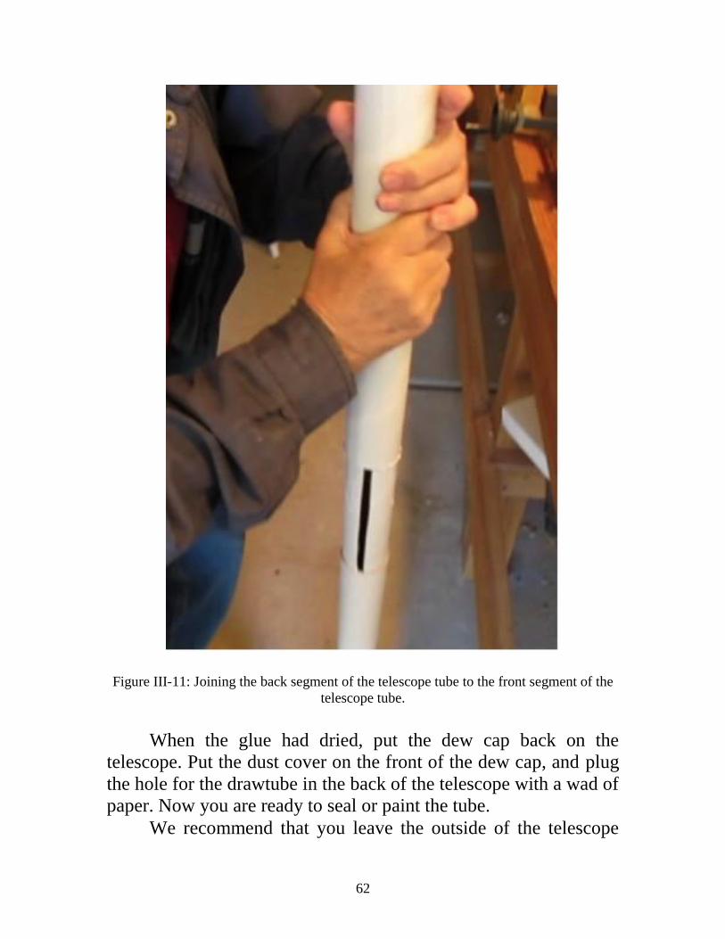
62
Figure III-11: Joining the back segment of the telescope tube to the front segment of the
telescope tube.
When the glue had dried, put the dew cap back on the
telescope. Put the dust cover on the front of the dew cap, and plug
the hole for the drawtube in the back of the telescope with a wad of
paper. Now you are ready to seal or paint the tube.
We recommend that you leave the outside of the telescope

63
white, i.e., the original color of the cardboard tubes. If you decide
to leave the tubes white, you may also want to paint the back of the
wooden ring at the back of the end of the tube white. This is up to
you. Alternatively, you can spray paint the telescope tube any color
you want, but if you leave the telescope white, it will be easier to
sight along the telescope tube to find objects in the dark of the
night. If you want you keep the tubes white, you need to seal them
by spraying the entire outside (except the dust covers) of the tube
with clear Krylon spray paint to protect the cardboard from the
moisture of the night (or any rain if you forget to take the telescope
inside after using it). You should give the tubes several coats of
Krylon (or colored paint) to ensure that the tube is well protected
against moisture (or rain), otherwise moisture from dew or very
high humidity may cause the telescope tube to warp.
When the Krylon (or colored) spray paint is completely dry,
take the dew cap off, put the objective lens back in its cell, put the
dew cap back on the telescope tube, take the paper plug out of the
back of the telescope, slide the drawtube back into the wooden
rings until about 4 inches of it are sticking out and put the 2-inch
FL eyepiece back in the drawtube. Now you have a beautiful
telescope of your own making.
There are three things you need to do to care for your
telescope:
First, when not using it, keep the dust cap on the objective
end of the telescope to keep dust and dirt from getting of the
objective lens on the telescope;
Second, when you are not using them, keep the dust caps on
the eyepieces and;
Third, do not leave the telescope out in the sunlight or
outside overnight when you are not using it. Despite the protective
coating of Krylon or paint, the cardboard tube may warp from the
heat of direct sunlight if exposed to the sun for prolonged periods
of time and due to dew forming on it during the night. So keep the
telescope indoors when not in use.

64
Part IV: Making the Mounting
In order to build the telescope mount and tripod, in addition
to the variable speed power drill, wood and metal drill bits, a
countersink bit, wood clamps and/or heavy weights and a drill
mounting mentioned in Part II, you will need to buy (or have or
have access to):
1) A table saw or a miter box and a miter saw,
2) A 1-inch x 6-inch pine board* about 2-feet long,
3) Six, 1-inch x 2-inch x 8-foot long, pine laths**,
4) A piece of ¼- to ½-inch thick plywood about 1 x 1-
foot,
5) 75, 1½ -inch long, number 10, flathead wood screws
6) A 3-inch long, 3/8-inch diameter, full threaded
hexhead bolt,
7) A 3/8-inch hexnut,
8) A 2-inch diameter, ½ -inch washer,
9) Two 3/8-inch, lock washers,
10) A 1¼-inch diameter, 3/8-inch washer,
11) A 3/8-inch wingnut,
12) Two 2½-inch long, 5/16-inch diameter, full threaded
hexhead bolts,
13) Four 5/16-inch hexnuts,
14) Four 5/16-inch, lock washers,
15) Four 5/16-inch washers,
16) A 5/16-inch wingnut,
17) Six 3-inch long, ¼-inch, hexhead bolts,
18) Six ¼-inch hexnuts,
19) Twelve ¼-inch washers,
20) Three ¼-inch wingnuts, and
21) Two, 14-inch long cable ties.

65
Notes:
* A 1-inch x 6-inch board is really ¾-inches thick and 5½-inches
wide and will be referred to as such in the following.
** 1-inch x 2-inch pine laths are ¾-inches thick and 1½-inches
wide and will be referred to as such in the following.
Unless you made the mounting while you were making the
optics and the telescope, you are ready to do so now. But, before
you start, there are several things you must know and do to make
the mounting.
The first thing to take serious note of is: Without a solid
mount, any telescope—no matter how good the optics are—is
nearly useless. If your mount is not well made and solid, you will
have a hard time pointing the telescope at an object and an even
harder time keeping the object in the field of view and when it is in
the field of view, the telescope will be shaking so you won’t really
see much. So make sure you follow our instructions and make your
mount SOLID.
The second thing is: Since your telescope is over 5-feet long,
the tripod must be tall enough so you can comfortably view
celestial objects. Our rule of thumb is—make the tripod legs as
long as the distance from the floor to about your upper chest.
The third thing is: Do you want to varnish or paint the
wooden parts of the mounting or leave them unpainted? If you
want to varnish or paint (whatever color you want) the mount, do
so after you have constructed its parts, but before you have finally
assembled them. Also, make sure you do not paint or varnish the
various bolts, nuts and washers that together make the vertical and
horizontal axes of the mounting and those that hold the legs to the
tripod leg support and the tripod platform to the legs.
The fourth thing is: You will need a table saw and/or miter
box and miter saw to make the wood cuts true and accurate,
otherwise the tripod parts - and especially the telescope yoke and
saddle parts - will not fit together properly and that will weaken
your telescope mounting markedly.

66
The fifth thing is: You need to smooth each wooden element
of the mounting with a wood file and sandpaper after you have cut
it to shape.
Finally, there are three parts to the mounting—the tripod, the
yoke and the saddle.
The Tripod
The Tripod’s Leg Support
Draw to scale the pattern called “Top” in Figure IV-1 on a
piece of ¾-inch thick piece of pine board that is at least 5¼-inches
tall and 6-inches wide and cut out the hexagonal top of the leg
support. Drill the 3/8-inch diameter central hole through the wood,
drill six pilot holes for the screws through the wood using a 3/16-
inch drill bit as shown on the patterns, and then countersink the
screw holes.
Take a ¾-inch by 1½-inch lath and cut three, 2-inch long
pieces off of it. Using the pattern in Figure IV-2, drill a ¼-inch
hole in each of the three pieces of wood. Draw to scale the pattern
labeled “Bottom” in Figure IV-1 on the bottom of the hexagonal
leg support and use Elmer’s glue to glue the three pieces of wood
onto the bottom of the hexagonal part of the leg support. Use wood
clamps or heavy weights to tightly hold the glued parts together.
Let the glue dry.
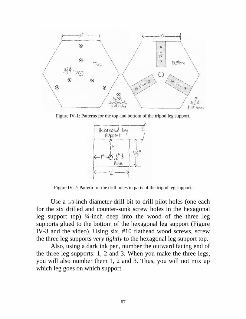
67
Figure IV-1: Patterns for the top and bottom of the tripod leg support.
Figure IV-2: Pattern for the drill holes in parts of the tripod leg support.
Use a 1/8-inch diameter drill bit to drill pilot holes (one each
for the six drilled and counter-sunk screw holes in the hexagonal
leg support top) ¾-inch deep into the wood of the three leg
supports glued to the bottom of the hexagonal leg support (Figure
IV-3 and the video). Using six, #10 flathead wood screws, screw
the three leg supports very tightly to the hexagonal leg support top.
Also, using a dark ink pen, number the outward facing end of
the three leg supports: 1, 2 and 3. When you make the three legs,
you will also number them 1, 2 and 3. Thus, you will not mix up
which leg goes on which support.

68
Figure IV-3: Diagram for drilling the pilot holes in parts of the tripod leg support.
Now put a lock washer on the 3/8-inch by 3-inch hex-head
stove bolt and insert the bolt into the 3/8-inch diameter hole in the
bottom of the hexagonal leg support (Figure IV-4). Put a 3/8-inch
lock washer and a 3/8-inch hex-nut on the bolt sticking out the top
of the hexagonal leg support and tighten the nut on the bolt as tight
as possible. Make absolutely sure the nut and bolt are very, very
tight before proceeding. This bolt is the vertical axis of your
mount.
Figure IV-4: Photo of the positioning of the 3/8-inch stove bolt in the leg support and
support ring.

69
Using the pattern in Figure IV-5 and a 2-inch hole saw, cut a
2-inch diameter disk out of ¾-inch thick board, and, using a 1-inch
wood drill, drill a 1-inch diameter hole in its center. Also, drill
three, 3/16-inch diameter pilot holes in the wooden ring and
countersink the holes. Then, using Elmer’s glue, glue this wooden
ring to the top of the hexagonal leg support so the ring surrounds
the hex-head nut holding the bolt and the pilot holes are not over
the three leg supports on the bottom side of the leg support (Figure
IV-4). Press down hard on the ring to insure there is good contact
between the ring and the hexagon leg support as the glue dries.
Figure IV-5: Pattern for the wooden disk for the top of the tripod leg support.
When the glue is completely dry, use a 1/8-inch diameter drill
bit to drill pilot holes (one each for the three drilled pilot holes) ¾-
inch deep into the wood of the hexagonal top of the leg support
(see the video). Using three, #10 wood screws, screw the ring very
tightly to the hexagonal leg support top (Figure IV-4).
The Tripod’s Legs
Using the various ¾-inch by 1½-inch laths, cut three pieces
of lath 6-inches long, nine pieces of lath 3-inches long and six
pieces that are as long as the distance from the floor to about the
middle of your upper chest.
Using the pattern in Figure IV-6, trim three of the 6-inch long
pieces of lath to make the feet of the three legs.
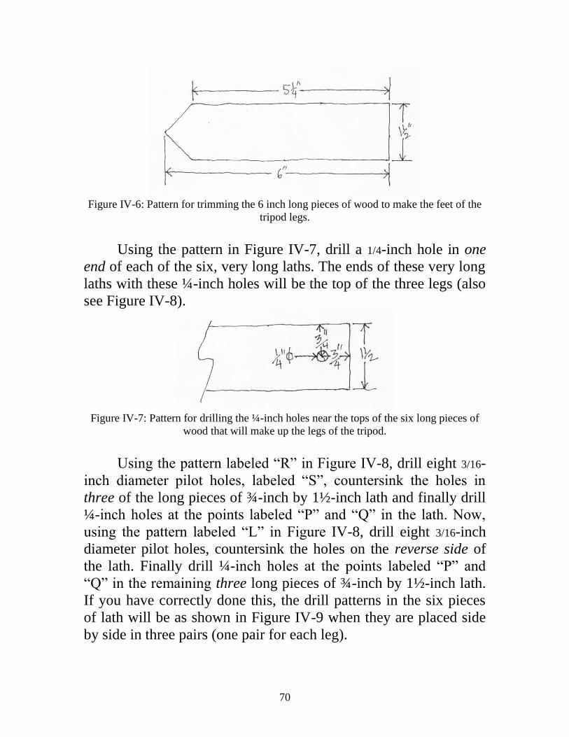
70
Figure IV-6: Pattern for trimming the 6 inch long pieces of wood to make the feet of the
tripod legs.
Using the pattern in Figure IV-7, drill a 1/4-inch hole in one
end of each of the six, very long laths. The ends of these very long
laths with these ¼-inch holes will be the top of the three legs (also
see Figure IV-8).
Figure IV-7: Pattern for drilling the ¼-inch holes near the tops of the six long pieces of
wood that will make up the legs of the tripod.
Using the pattern labeled “R” in Figure IV-8, drill eight 3/16-
inch diameter pilot holes, labeled “S”, countersink the holes in
three of the long pieces of ¾-inch by 1½-inch lath and finally drill
¼-inch holes at the points labeled “P” and “Q” in the lath. Now,
using the pattern labeled “L” in Figure IV-8, drill eight 3/16-inch
diameter pilot holes, countersink the holes on the reverse side of
the lath. Finally drill ¼-inch holes at the points labeled “P” and
“Q” in the remaining three long pieces of ¾-inch by 1½-inch lath.
If you have correctly done this, the drill patterns in the six pieces
of lath will be as shown in Figure IV-9 when they are placed side
by side in three pairs (one pair for each leg).

71
Figure IV-8: Top two drawings - pattern for drilling the holes in the six long pieces of
wood that will make up the three legs of the tripod; Bottom drawing - details of the
pattern for drilling the holes in the six long pieces of wood that will make up the three
legs of the tripod.
Note that the ¼-inch diameter holes Q are drilled on the centerline of the laths (e.g., see
Figure IV-7 for P).
Do the following to assemble each of the three legs: Lay one
of the two long laths of a leg pair with it counter-sunk drill holes
downwards on a flat surface. Spread Elmer’s glue: A) on one side
of the upper 3 inches of the 6-inch long leg foot; and B) on one
side of each of the three, 3-inch long pieces of lath we call leg
braces. As shown in the video, place the glued side of the leg foot
and the three 3-inch leg braces on the long pieces of lath. Press
down very hard to very tightly squeeze the glued pieces together.
Next, spread glue

72
Figure IV-9: Photo of how the three pairs of long leg boards should look after drilling
(and countersinking) the hole in the boards.
on the exposed sides of the top 3 inches of the leg foot and the
three 3-inch long braces. Place the second long piece of lath of the
leg on the glued surfaces and again press down very hard. Now,
rotate the leg so it is standing on an edge and, using four wood
clamps, clamp each of the glued wooden pieces tightly together.
Let the glue dry.

73
Use a 1/8-inch diameter drill bit to drill a pilot hole ¾-inch
deep into the lath in each of the eight drilled and counter-sunk
screw holes of the leg foot and the three leg braces of each leg.
Turn the leg over and drill the pilot holes for the eight drilled and
counter-sunk screw holes on that side of the leg. Screw sixteen,
#10 flathead wood screws very tightly into the sixteen screw holes.
Repeat the above process to make the other two legs.
As shown in Figure IV-10, slide the top of one of the legs
over a leg support on the bottom of the hexagonal leg support, so
the 1/4 -inch holes in leg and the leg support coincide. Put 1/4 -inch
washer on the 1/4-inch, 3-inch long hexhead stove bolts, slide the
bolt through the holes, put 1/4-inch washer on the protruding bolt
and put two hexnuts on the bolt. Use two crescent wrenches to
very securely tighten the bolt and nuts on the leg. Repeat the
process for the remaining two legs. Adjust the legs so they are at
about a 30 degree angle to the vertical and that the top of the
hexagon leg support is level.
Figure IV-10: Photo of joining the legs to the tripod support structure. Now, using a dark ink pen, number the legs, 1, 2, and 3,
corresponding to the numbers on the outward facing end of the
three leg supports.
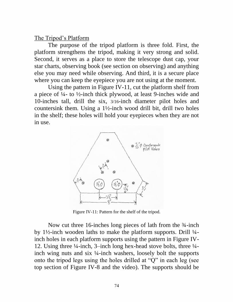
74
The Tripod’s Platform
The purpose of the tripod platform is three fold. First, the
platform strengthens the tripod, making it very strong and solid.
Second, it serves as a place to store the telescope dust cap, your
star charts, observing book (see section on observing) and anything
else you may need while observing. And third, it is a secure place
where you can keep the eyepiece you are not using at the moment.
Using the pattern in Figure IV-11, cut the platform shelf from
a piece of ¼- to ½-inch thick plywood, at least 9-inches wide and
10-inches tall, drill the six, 3/16-inch diameter pilot holes and
countersink them. Using a 1½-inch wood drill bit, drill two holes
in the shelf; these holes will hold your eyepieces when they are not
in use.
Figure IV-11: Pattern for the shelf of the tripod.
Now cut three 16-inches long pieces of lath from the ¾-inch
by 1½-inch wooden laths to make the platform supports. Drill ¼-
inch holes in each platform supports using the pattern in Figure IV-
12. Using three ¼-inch, 3–inch long hex-head stove bolts, three ¼-
inch wing nuts and six ¼-inch washers, loosely bolt the supports
onto the tripod legs using the holes drilled at “Q” in each leg (see
top section of Figure IV-8 and the video). The supports should be

75
long enough to nearly touch at the center axis of the tripod, but not
so long that they overlap. If they do overlap, spread the tripod legs
until the supports just touch at the center.
Figure IV-12: Drill hole pattern for the three platform supports.
Now, using a dark ink pen, number the three platform
supports, 1, 2, and 3, corresponding to the numbers on the outward
facing end of the three leg supports and the legs themselves.
Following the video and Figure IV-13, carefully aligning the
platform shelf on one of the three platform supports so the support
is exactly centered under the two screw holes on the platform shelf.
Insert a soft lead pencil in each of the two screw holes, mark where
the hole fall on the support. As in the video, using a 1/8-inch drill
bit, drill screw pilot holes ¾-inch deep exactly centered at each of
the two pencil marks on the top of the platform support. Now,
using two #10 screws, screw the platform onto the support.
Following the video, repeat the process for the other two platform
supports.

76
Figure IV-13: Photo showing how to prepare for gluing and drilling the pilot holes in the
three shelf supports.
When you are finished with the shelf, the tripod is done,
unless you want to varnish or paint it. If you do want to varnish or
paint it, disassemble it and paint each part separately before
reassembling the tripod. If you varnish or paint the tripod, make
sure you redo the numbering of the legs, their supports and the
platform supports.
The Mounting’s Yoke
Using a table saw or miter box and miter saw, cut two pieces
2-inches wide and 7-inches long and two pieces 2-inches wide and
5-inches long from the ¾-inch thick pine board, following the
pattern Figure IV-14. Then drill two 3/16-inch diameter pilot screw
holes and countersink them in the two 7-inch pieces and then drill
a 5/16-inch hole at the other end of each piece. Following the video,
put Elmer’s glue in the ends of one of the 5-inch long pieces. Lay
that piece on a flat surface. Place the two 7-inch long pieces, with
the counter sunk screw holes facing outwards, on the glued ends of
the 5-inch piece and squeeze the pieces of lath together. Now place
the unglued 5-inch piece between the other ends of the 7-inch long

77
pieces and use wood clamps or heavy weights to put pressure on
the 7-inch long pieces (Figure IV-15) so they fit tightly to the 5-
inch pieces.
Note: The second 5-inch long piece, which is not glued to the
7-inch long pieces, is used only to keep the yoke true and is
removed when the glue on the other end is dry.
Figure IV-14: Size of the wood and the pattern for drilling the screw holes in two of the
pieces of wood that make the yoke.
Figure IV-15: Photo showing the weighting of yoke parts

78
When the glue is dry, take off the wood clamps or weight and
using a 1/8-inch drill bit, drill two pilot holes ¾-inch deep into each
of the 5-inch long piece. Then use four #10 wood screws to very
tightly screw the 7-inch long pieces to the 5-inch long piece. Now
your yoke is finished (Figure IV-16), unless you want to varnish or
paint it.
Figure IV-16: The finished yoke.
As in video, put a 2-inch diameter, 3/8-inch washer on the
part of the 3/8-inch stove bolt sticking out the top of the tripod,
slide the bottom of the yolk onto the 3/8-stove bolt, put a 3/8-inch
washer over the stove bolt and then screw a 3/8-inch wing nut onto
the bolt.
When you want to clamp the telescope in one position, you
tighten this wing nut and when you want to move the telescope in

79
azimuth (left and right), you loosen the wing nut. Now the yoke is
finished.
The Telescope’s Saddle
Following the patterns in Figure IV-17, use the table saw or miter
box and miter saw and a 2-inch diameter hole saw, cut two 2-inch
x 3½-inch saddle side-pieces and four 2-inch x 31/8-inch saddle
end-pieces from the ¾-inch thick pine board. Using the pattern in
Figure IV-17, drill two 3/16-inch pilot holes in each of the four
saddle end-pieces and countersink the holes. Then drill a 5/16-inch
hole in the center of each of the two saddle side-pieces.
Figure IV-17: Patterns for cutting the telescope saddle parts and for drilling the holes in
the four saddle end pieces of wood.
Wrap some medium grained sandpaper around the telescope
tube and sand the arcs cut in the wood of the four end-pieces until

80
the tubes fit snuggly in the wooden four end-pieces.
Following the video, put Elmer’s glue on the 2-inch wide
ends of the 3½-inch long saddle side-pieces of wood, lay those
pieces of wood on a flat surface. Squeeze the four saddle end-
pieces of wood, with the counter sunk screw holes facing
outwards, onto the glued ends of the two saddle side-pieces and
clamp the pieces together.
When the glue is dry, take off the wood clamps and, using a
1/8-inch drill bit, drill the pilot holes ¾-inch deep into each end the
two saddle side-pieces. Then use eight #10 wood screws to very
tightly screw the 2-inch wide saddle end-pieces to the two saddle
side-pieces. Now the two parts of your saddle are finished, unless
you want to varnish or paint them.
As in Figure IV-18 and the video, put 5/16-inch lock washers
on the two 5/16-inch, 2½-inch long, hex-head stove bolts and insert
the bolts with the lock washers into the 5/16-inch holes in the inside
of the side-pieces of the two saddle parts. Then place 5/16-inch lock
washers and 5/16-inch hexnuts on the two stove bolts and, using
two crescent wrenches, tighten, very tightly, the 5/16-inch hexnuts
onto the stove bolts.
As in Figure IV-18 and the video, put a 5/16-inch washer on
the stove bolt of each saddle part, insert the stove bolt of each
saddle part into the 5/16-inch hole in the top of each prong of the
yoke, put a 5/16-inch washer on each stove bolt sticking out the side
of each yoke prong and then screw two 5/16-inch hexnuts on one of
the bolts and a 5/16-inch wing nut on the other bolt. These two 5/16-
inch bolts form the horizontal axis of your mount.

81
Figure IV-18: Mounting of the two 5/16-inch stove bolts in the two sides of the saddle.
When you want to clap the telescope in one position, you
tighten the wing nut and when you want to move the telescope in
altitude (up and down), you loosen the wing nut. Now the saddle
and the entire mount are finished (Figure IV-19).
Figure IV-19: Photo of the finished saddle parts mounted in the yoke.

82
Mounting the Telescope on the Mount
Find the balancing points of the telescope, first with the 2-
inch FL eyepiece and then with the 1-inch FL eyepiece in the
drawtube, when the eyepieces are focused on a very distant object.
The differences in these two balancing points will be very small.
Using the average of these two balancing points as your point of
reference, slide the telescope into the saddle until the balancing
reference point is in the middle of the saddle.
Take two, 14-inch long cable ties and wrap one around each
end of the saddle to secure the telescope in the saddle. In order to
get the cable ties as tight as possible, you will need to shape each
tie to the shape of the saddle by bending each tie, where it crosses
each corner of the saddle, with your fingers and then secure the
cable ties very tightly, using a pair of pliers, as all shown in the
video.
Congratulations, now you have completed your simple
telescope (see title page) and are ready to start using it as soon as it
is night and the Moon, planets and stars are out.

83
Part V: Getting Started Observing
WARNING—DO NOT USE YOUR TELESCOPE TO
LOOK AT THE SUN. If you do, you may blind yourself. You can
observe the Sun safely by projection as described in the note in
Appendix A.
Also, when you are not using your telescope, 1) put one of
the plastic caps, that came with the mailing tubes, in the front of
the dew cap to keep dust from getting on the objective lens, 2)
cover the eyepieces with the plastic dust caps, and 3) keep the
telescope indoors, otherwise the sun and the weather may warp the
cardboard tube so it is no longer straight.
Now, as you are getting ready to start observing, you will
find it very useful and rewarding if you keep a logbook of your
observations. Use this logbook to record:
A) The date and time of the observations,
B) The telescope used (lens diameter and focal ratio—the focal
ratio is simply the focal length of the lens divided by the
lens’ diameter, in this case it is 60-inches/1.5-inches and is
written as F/40),
C) The magnification used,
D) The transparency of the sky (from 1 to 5, where 1 is very
hazy and 5 is completely clear),
E) The seeing (from 1 to 5, where the image is blurry and 5 the
image is sharp and steady),
F) A drawings of what you saw and
G) Comments about what you observed.
There are a few other important facts about your telescope
you need to know.
First: As you may already know, the average human can see
stars down to the 6th
magnitude in a clear, dark, country sky with
no Moon out. Your 1½-inch telescope will let you see stars down

84
to about the 9th
magnitude under these conditions. However, the
objects we have listed in Appendix A are generally limited to those
brighter than about 8th
magnitude, which you will most probably
be able to see under good conditions—if you live in the country or
a small town, but not a big city (where you will have trouble even
seeing the brighter stars and planets).
Second: The theoretical resolving power of a perfect 1½-inch
telescope is 3 arc-seconds (1 degree has 60 arc-minutes and each
arc-minute has 60 arc-seconds). However, since your telescope has
a single element, non-achromatic lens, we expect that its resolving
power will probably be about 5 arc-seconds.
For comparison, the Moon’s apparent diameter is about ½ of
a degree or about 1800 arc-seconds and its real diameter is 2160
miles. So your telescope’s resolution corresponds to about 6 miles
on the Moon.
Another example is Jupiter, whose apparent maximum
diameter is nearly 50 arc-seconds, so you will be able to see jovian
features nearly as small as 1/10th
the diameter of Jupiter.
Given that the best resolution we expect your telescope will
have is about 5 arc-seconds, the list of, e.g., double stars, in
Appendix A is limited to those stars that are separated by more
than 5 arc-seconds. However, when observing double stars, the
difference in the brightness between the primary (brighter) and
secondary (dimmer) star also has an effect on ones ability to
resolve the two stars. The theoretical resolving power of a lens (or
mirror) is valid only if the two stars are of equal brightness. The
dimmer the secondary star is with respect to its primary, the farther
apart the two stars have to be to be able to see the secondary in the
glare of its brighter primary.
Also, dim objects like diffuse nebulae and galaxies are hard
to recognize unless they are bigger than a few arc-minutes, or more
than 10 times the resolution of the telescope.
The first object you will probably look at is the Moon. Start
with the 2-inch FL eyepiece that gives you 30x and has a FOV of
nearly 1.1-degrees, i.e., about two times the diameter of the Moon.

85
At first, you may have trouble even finding the Moon, but with a
little patience and practice you will get the Moon in the field of
view, learn to keep it there and get it in focus—and then, at 30x,
you will see the craters, mountains, marae and other detail of the
lunar surface. Next, put the 1-inch FL eyepiece, which as a FOV of
nearly 0.5-degrees in the telescope and at 60x you will see even
more detail. With more and more practice you will find it easier
and easier to locate not only the Moon, but also the brighter planets
and stars in the sky and then the dimmer and dimmer ones.
If you already know the constellations and have “Sky and
Telescope” and/or “Astronomy” magazine(s), you already know
where and when to observe the planets of our solar system. But, in
order to find the majority (but not all) of the double stars, galactic
star clusters, diffuse nebulae, planetary nebulae, globular star
clusters and some of the galaxies beyond our own Milky Way
(listed in Appendix A), you will not only need to know the
constellations (see below), but you will also need to use star charts.
Star charts are essential for anyone who is serious about
observational astronomy and there are a number of excellent books
that you can use to learn where these various objects are in the sky,
several of which have been written by KG and are available from
Ken Press.
If you do not yet know the constellations and don’t get “Sky
and Telescope” and/or “Astronomy”, you will need to start
learning the constellations if you want to get the full use of your
telescope and want to fully enjoy astronomy. There are many
books and tools you can use to learn the constellations. One such
tool is a planisphere that you can get from Ken Press.
Alternatively, the constellation book recommended by AB is “The
Stars” by Rey (Appendix B).
If you are just starting to learn the constellations and do not
know where the planets are in the night sky, point your telescope
to the brightest objects in the sky and:
If the object is a star, it will appear as a point of light at both
30x and 60x.

86
If the very bright object is whitish, has a disk, even at 30x,
and has up to four medium bright stars, more or less, in a line on
either side of the disk, you have “discovered” Jupiter and it four
brightest satellites. To be certain it is Jupiter, look at it on a
following night and if it is Jupiter, you will see that the satellites
have changes positions. If you see less than four satellites, one or
more are either behind Jupiter (occulted by Jupiter), or in eclipse in
Jupiter’s shadow or are in front of Jupiter (transiting Jupiter).
If the bright object is yellowish, shows a small disk and has a
ring around it—you have “discovered” Saturn and its Rings.
If you look at a very bright star to the east in the morning sky
or to the west in the evening sky and it has the gibbous shape of
our Moon a few days before or after full Moon, or has a half-moon
shape, or has a crescent shape, you have “discovered” Venus.
Venus goes through its phases, from full to crescent in the evening
sky and from crescent to full in the morning, each in about nine
months. Take note of the fact that, because Venus is so bright, it is
best viewed when the sky is still very bright soon after sunset and
shortly before sunrise. If the sky is too dark, the glare of Venus
will be so bright that you will have difficulty seeing its phase.
If you look at a bright, reddish star in the night sky and it has
a small disk, then you have “discovered” Mars. However, most of
the time during its 26-month observational cycle, Mars is too small
to show a disk, so, until you know your way around the
constellations, you will have trouble identifying Mars.
Once you have learned the constellations and have more
observing experience, you will be able to locate most, if not all, of
the objects we have listed in Appendix A, assuming you do not
have city lights bothering you.
We note here that the lists in Appendix A do not include
every object you might be able to observe with your simple
telescope. For example, we have resolved some double stars as
close as 4 arc-second (e.g., Alpha Gemini or Castor which has a
separation of 4.6 arc-seconds) using the telescope shown in the
illustrations of this manual, but our ability to do so is a result of

87
our having decades of observing experience. So, with time, you
may be able to add to the list of double stars given in the appendix.
Also, there are many dim and small deep sky objects (e.g.,
planetary nebulae, globular clusters and galaxies, almost all of
which are dimmer than 6th
magnitude) that are within reach of your
telescope, but not in the lists in Appendix A. They are excluded
from the lists because they are not close enough to a star (visible to
the naked eye) you can use as a reference so you can find the dim
object. The following two paragraphs illustrate this point.
There are just two planetary nebula that we have listed in
Appendix A - the famous Ring Nebula in Lyra and the Dumbbell
Nebula. The Dumbbell is fairly bright and big (8th
magnitude and
5x8 arc-minutes) and is relatively easy to find, while the Ring
Nebula is dimmer and smaller (9th
magnitude and about 1 arc-
minute is diameter) and you would miss it if it were not located
halfway between two fairly bright stars is Lyra. Even so, you will
find it hard to identify the Ring Nebula. There are several
additional planetary nebulae that are about as bright, or brighter
than the Ring Nebula, and about the same size, but they are all
located far from any naked eye star and thus are very difficult to
locate and identify with your simple telescope.
Further, we have listed the faint (8th
magnitude and small (3
arc-minutes in diameter), elliptical, satellite galaxy (M32) of the
Great Nebula (galaxy) in Andromeda (M31, 5th
magnitude, 20x60
arc-seconds), because the former is just visible right next to the
latter. However, if M32 were not right next to M31, you would
have great difficulty finding it with your simple telescope. As is
the case with the planetary nebulae cited above, there are several
galaxies with magnitudes of 8 and 9 that are not listed, because
they are not near a reference star and are thus very difficult to
locate and identify.
In contrast to galaxies, planetary nebulae and diffuse nebulae,
many globular clusters are relatively easy to find and identify, even
if the brighter ones are not near a naked eye star. This is because
many are large (several to tens of arc-minutes in diameter), fairly

88
bright and have a characteristic, fuzzy ball shape that, once you
have observed several of them, you will easily recognize them.
In addition, there are many open or galactic star clusters that
are within the reach of your simple telescope, but are not listed in
the appendix. As you might guess from their name, these clusters
of young stars are found in—or close to—the Milky Way (our
galaxy). Since (as you will see in your telescope), there are
numerous stars in the Milky Way, it is often difficult to identify a
galactic cluster that is located in the Milky Way from the
background Milky Way stars. This is the case unless the cluster is
very compact and its stars are relatively bright. Thus, most of the
galactic clusters listed in the appendix are adjacent to the Milky
Way, e.g., the Praesepe (M44) and the Pleiades (M45). But, with
experience, you may be able to locate some of the galactic clusters
in the Milky Way that are not in our list in Appendix A.
Finally, from our experience, we are sure you will enjoy
learning to use your home made, simple telescope to observe the
Moon, the planets and the binary stars and deep sky objects of our
universe listed in this manual. We hope the experience you have
making your own telescope and observing with it, will encourage
you to grind, polish and figure telescopic mirrors for much more
capable telescopes like those shown in Figures I-1 and I-2. Such
telescopes will give you much better views of the objects listed in
Appendix A and will allow you to locate many more such objects,
as well as see fine detail on the Moon, Mars, Jupiter and Saturn.
We also hope that this experience will encourage you to choose
astronomy, optics or planetary science as a career.

89
Appendix A:
Astronomical Objects that can be Observed
with this Simple, Beginner’s Telescope
Solar System Objects:
Sun* – Sunspots, Solar Eclipses, Transits of Mercury.
Mercury - Phases.
Venus – Phases.
Moon – Craters, Mountains, Marae, Lunar Eclipses.
Asteroids** – A few of the brightest ones.
Jupiter – Its two main cloud belts and its four brightest satellites.
Saturn and its Rings.
Uranus.**
Comets.
Notes:
* Do not look at the Sun directly with your telescope or you could
be blinded. But you can look at the Sun by projection as follows:
Cut a 19/16-inch diameter hole in a stiff piece of paper 6 or so
inches square. Slide the paper over the drawtube of the telescope
and push it flush against the back of the telescope tube. Put the 30x
eyepiece in the drawtube and focus the eyepiece on a very distant
object. Point the telescope towards the Sun and hold a white sheet
of stiff paper, again 6 or so inches square, several inches behind
the eyepiece. Refocus the eyepiece until the sun’s image is sharp.
You will see a 3- or 4-inch diameter image of the Sun projected on
the white paper and you (and any companions) will see sunspots (if
there are any on the Sun when you observe) and/or watch a partial
solar eclipse and/or a transit of Mercury in comfort and with no
danger to you eyesight.
** Located and followed only with the aid of star charts. Since
Uranus and the brighter asteroids are only as bright as sixth or
seventh magnitudes and are too small (Uranus is less than 4 arc-

90
seconds in diameter and the largest asteroids are less than 1 arc-
second in diameter) to show a disk, you will only know if you have
found them by noting (and drawing) their positions with respect to
nearby stars on successive nights and seeing them move from night
to night.
Double Stars:
The following table of double stars gives the following
information:
The Constellation the stars are in,
The Name of the star,
RA – the Right Ascension Coordinate of the stars in hours (h) and
minutes (m),
Dec – the Declination Coordinate of the stars in degrees north or
south (-) of the celestial equator,
PA – the Position Angle of the secondary (dimmer) star with
respect to the primary (brighter) star given in degrees and
measured counterclockwise from celestial north,
Sep – Separation of the secondary star from the primary star
measured in arc-seconds,
M1 – Magnitude of the primary star, and
M2 – Magnitude of the secondary star.
Constellation Star RA Dec PA Sep M1 M2 Aries Gamma 1h 53m 19 0 7.5 4.5 4.6 Lambda 1h 58m 24 47 36.7 4.8 6.7 Bootes Iota 14h 16m 51 32 38.7 4.8 7.4 Delta 15h 15m 33 78 103.8 3.6 7.9 Mu 15h 24m 37 170 107.1 4.3 7.1 Cancer Iota 8h 47m 29 308 30.7 4.1 6.0 Canes Venatic Alpha 12h 56 m 38 229 19.3 2.9 5.5 Canis Major h 3945 7h 17m -23 52 26.8 5.0 5.8 Capericornus Alpha 20h 18m -13 292 381.2 3.7 4.3 Cassiopeia SHJ 355 23h 30m 59 268 75.8 4.9 7.2 Cententarus 3 13h 52m -33 106 7.9 4.5 6.0 Cepheus Delta 22h 29m 58 191 40.6 4.2 6.1 Cygnus Beta 19h 31m 28 55 34.7 3.4 4.7

91
Delphinus Gamma 20h 46m 16 266 9.1 4.4 5.0 Draco Nu 17h 32m 55 311 63.4 4.9 4.9 Psi 17h 42m 72 15 30.0 4.6 5.6 Eridanus Theta 2h 58m -40 90 8.4 3.2 4.1 f 3h 49m -38 217 8.4 4.7 5.3 Hercules 95 18h 2m 22 257 6.3 4.9 5.2 Hydra Tau1 9h h 29m -3 5 66.2 4.6 7.3 Lepus Gamma 5h 44m -22 350 96.9 3.6 6.3 Lyra Epsilon 18h 44m 40 174 210.5 5.0 5.3 Zeta 18h 45m 38 150 43.8 4.3 5.6 Beta AB 18h 50m 33 150 45.4 3.6 6.7 Monoceros 8 Epsilon 6h 24m 5 29 12.1 4.4 6.6 Beta AB 6h 29m -7 133 7.1 4.6 5.0 Orion Delta 5h 32m 0 0 52.8 2.4 6.8
747 5h 35m -6 224 36.0 4.7 5.5 Puppis Kappa 7h 39m -27 318 9.8 4.4 4.6 Scorpius Beta 16h 5m -20 20 13.6 2.6 4.5 Nu Aa-C 16h 12m -19 337 40.8 4.2 6.6 Serpens Theta 18h 56m 4 104 22.3 4.6 4.9 Taurus 88 4h 36m 10 300 69.1 4.3 7.8 Tau 4h 42m 23 214 63.0 4.2 7.0 Ursa Major Alpha 11h 4m 62 204 381.0 2.0 7.0 Zeta 13h 24m 55 153 14.3 2.2 3.9
Open or Galactic Star Clusters*:
The following table of open or galactic clusters gives the
following information:
The Constellation the galactic cluster is in,
The Name of the cluster,
RA – the Right Ascension Coordinate of the galactic cluster in
hours (h) and minutes (m),
Dec – the Declination Coordinate of the galactic cluster in degrees
north or south (-) of the celestial equator,
Dia** – Rough estimate of the diameter of the galactic cluster in
arc-minutes,
Mag*** – Rough estimate of the magnitude of the galactic cluster.
Notes:

92
* Because Open Clusters are usually large and their stars are often
dim, many of those listed here are easier found and observed with
binoculars rather than with your simple telescope.
** The diameters and number of stars vary by, at least, a factor of
2 in different catalogs.
*** The magnitudes vary by up to 2 magnitudes in different
catalogues.
Constellation Name RA Dec Dia* Mag*
Auriga M 36 5h 37m 34 12 6
M 37 5h 53m 33 20 5
M 38 5h 29m 36 20 6
NGC 1857 5h 21m 39 9 7
Cancer M 44 1 8h 41m 20 90 4
Canis Major M 41 6h 47m -21 30 6
Gemini M 35 6h 10m 24 30 5
Hydra M 48 8h 15m -6 40 5
Monoceros NGC 2244 6h 33m 5 40 5
NGC 2264 6h 42m 10 20 4
NGC 2301 6h 53m 0 15 6
Ophiuchus NGC 6633 18h 28m 6 20 5
IC 4665 17h 47m 6 50 6
Orion NGC 1981 5h 36m -4 30 4
Iota Orionis 5h36m -6 30 4
Perseus M 34 2h 43m 43 30 6
NGC 869 2 2h 20m 57 30 5
NGC 884 2 2h 23m 57 30 5
Puppis M 47 7h 37m -15 20 5
M 93 7h 45m -24 20 7
NGC 2451 7h 46m -38 50 3
Sagittarius M 18 18h 21m -17 7 8
M 23 17h 58m -19 25 7
M 24 18h 15m -18 4 4
M 25 18h 33m -19 35 6
NGC 6530 3 18h 5m -24 10 5
Scorpius M 6 17h 41m -32 25 6
M 7 17h 55m -35 60 5
NGC 6231 16h 55m -42 15 5
NGC 6281 17h 6m -38 10 7
Serpens M 16 4 18h 19m -14 25 7
Taurus M 45 5 3h 48m 24 100 2

93
NGC 1647 4h 47m 19 40 6
NGC 1746 5h 5m 24 45 6
Note: 1 Praesepe or Beehive 2 Double Cluster in Perseus 3 Associated with the Lagoon Nebula, M 8
4 Associated with the Eagle Nebula, M 16
5 Pleiades
Diffuse Nebulae: The following table of diffuse nebulae gives the following
information:
The Constellation the diffuse nebula is in,
The Name of the diffuse nebula,
RA – the Right Ascension Coordinate of the diffuse nebula in
hours (h) and minutes (m),
Dec – the Declination Coordinate of the diffuse nebula in degrees
north or south (-) of the celestial equator,
Size – Size of the diffuse nebula in arc-minutes, and
Mag* – Magnitude of the diffuse nebula.
Note:
* The magnitudes vary by up to 2 magnitudes in different
catalogues.
Constellation Name RA Dec Size Mag
Orion M 42 1 5h 48m -5 66 5
M 43 2 5h 36m -5 17 9
M 78 5h 48m 0 7 8
Sagittarius M 8 3 18h 5m -24 40x90 6
M 17 4 18h 22m -16 10x40 7
Serpens M 16 5 18h 19m -14 30 7

94
Notes: 1 The Great Orion Nebula
2 Detached knot of the Great Orion Nebula 3 Lagoon Nebula, Associated with Open Cluster NGC 6530
4 Omega or Swan Nebula
5 Associated with Open Cluster NGC 6611
Planetary Nebulae: The following table of planetary nebulae gives the following
information:
The Constellation the planetary nebula is in,
The Name of the planetary nebula,
RA – the Right Ascension Coordinate of the planetary nebula in
hours (h) and minutes (m),
Dec – the Declination Coordinate of the planetary nebula in
degrees north or south (-) of the celestial equator,
Size – Size of the planetary nebula in arc-minutes, and
Mag* – Magnitude of the planetary nebula.
Note:
* The magnitudes vary by up to 2 magnitudes in different
catalogues.
Constellation Name RA Dec Dia Mag
Lyra M 57 1 18h 54m 33 1 9
Vulpecula M 27 2 20h0m 23 5x8 8
Notes: 1 Ring Nebula 2 Dumbbell Nebula
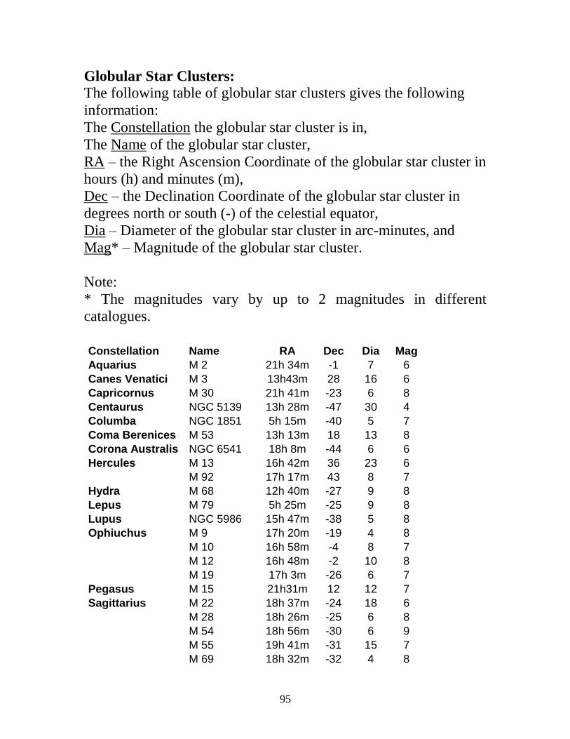
95
Globular Star Clusters:
The following table of globular star clusters gives the following
information:
The Constellation the globular star cluster is in,
The Name of the globular star cluster,
RA – the Right Ascension Coordinate of the globular star cluster in
hours (h) and minutes (m),
Dec – the Declination Coordinate of the globular star cluster in
degrees north or south (-) of the celestial equator,
Dia – Diameter of the globular star cluster in arc-minutes, and
Mag* – Magnitude of the globular star cluster.
Note:
* The magnitudes vary by up to 2 magnitudes in different
catalogues.
Constellation Name RA Dec Dia Mag
Aquarius M 2 21h 34m -1 7 6
Canes Venatici M 3 13h43m 28 16 6
Capricornus M 30 21h 41m -23 6 8
Centaurus NGC 5139 13h 28m -47 30 4
Columba NGC 1851 5h 15m -40 5 7
Coma Berenices M 53 13h 13m 18 13 8
Corona Australis NGC 6541 18h 8m -44 6 6
Hercules M 13 16h 42m 36 23 6
M 92 17h 17m 43 8 7
Hydra M 68 12h 40m -27 9 8
Lepus M 79 5h 25m -25 9 8
Lupus NGC 5986 15h 47m -38 5 8
Ophiuchus M 9 17h 20m -19 4 8
M 10 16h 58m -4 8 7
M 12 16h 48m -2 10 8
M 19 17h 3m -26 6 7
Pegasus M 15 21h31m 12 12 7
Sagittarius M 22 18h 37m -24 18 6
M 28 18h 26m -25 6 8
M 54 18h 56m -30 6 9
M 55 19h 41m -31 15 7
M 69 18h 32m -32 4 8

96
M 70 18h 44m -32 4 8
M 75 20h 7m -22 3 8
NGC 6723 19h 1m -37 7 6
Scorpio M 4 16h 25m -27 20 8
M 62 17h 2m -30 6 7
M 80 16h 14m -23 7 8
NGC 6388 17h 37m -45 4 7
Scutum M 11 18h 52m -6 14 6
Serpens M 5 15h 19m 2 13 6
Galaxies:
The following table of galaxies gives the following information:
The Constellation the galaxy is in,
The Name of the galaxy,
RA – the Right Ascension Coordinate of the galaxy in hours (h)
and minutes (m),
Dec – the Declination Coordinate of the galaxy in degrees north or
south (-) of the celestial equator,
Size – Size of the galaxy in arc-minutes, and
Mag* – Magnitude of the galaxy.
Note:
* The magnitudes vary by up to 2 magnitudes in different
catalogues.
Constellation Name RA Dec Size Mag
Andormeda M 31 0h 43m 41 20x60 5
M 32 0h 43m 41 3 8
Centaurus NGC 5128 13h 26m -43 9 7
Hydra M 83 13h 28m -30 8 8
Sculptor NGC 253 0h 48m -25 6x22 7
Ursa Major M 81 9h 56m 69 10x18 8
97
Appendix B: Reference Books, Papers and Magazines
All About Telescopes, S. Brown, Edmund Scientific Co.,
Tonawanda, NY, 1975.
Amateur Telescope Making - Book One, Ed. A.G. Ingalls,
Scientific American, Inc., NY.
Astronomy (magazine), Kalmbach, Publishing Co., P.O. Box
1612, Waukesha, WI 53187-1612.
Atlas of the Moon, C.A. Wood and M.J. Collins, Lunar Publishing,
UIAI Inc., Wheeling, WV
Binary Star Measurements with a 17th Century, Long-Focal,
Non-Achromatic Refractor, A.B. Binder, Journal of Double
Star Observations (e-journal), Vol. 6, #4, Oct. 1, 2010b.
Burnham’s Celestial Handbook, Vol. I, II & III, Dover
Publications, Inc., New York.
Double Stars for Small Telescopes, S. Hass, Sky
Publishing Co, Cambridge, MA.
Gleanings for ATM’s: A Telescope of the 17th
Century, A.B.
Binder, Sky & Telescope, pp. 444, April, 1992.
Making Your Own Telescope, A.J. Thompson, Sky Publishing Co,
Cambridge, MA.
Moon Map, Sky Publishing Co, Cambridge, MA.
Sky & Telescope (magazine), Sky & Telescope Media, 90
Sherman St., Cambridge, MA 02140-3264.
Stargazer, F. Watson, D A Capo Press, 2005.
The History of the Telescope, H.C. King, Sky Publishing Co,
Cambridge, MA.
The Next Step—Finding and Viewing Messier’s Objects, K.
Graun, Ken Press, Tucson, AZ.
The Performance Characteristics of 17th Century Long Focus,
Non-Achromatic Refractors, A.B. Binder, The Journal of the
Antique Telescope Society, Issue #31, Winter 2010a.

98
The Stars, H.A. Rey, Houghton Mifflin Co, Boston.
What’s Out Tonight, K. Graun, Ken Press, Tucson, AZ.
21st Century Atlas of the Moon, C.A. Wood and M.J.S. Collins,
Lunar Publishing, UIAI Inc. Wheeling WV, 2012.
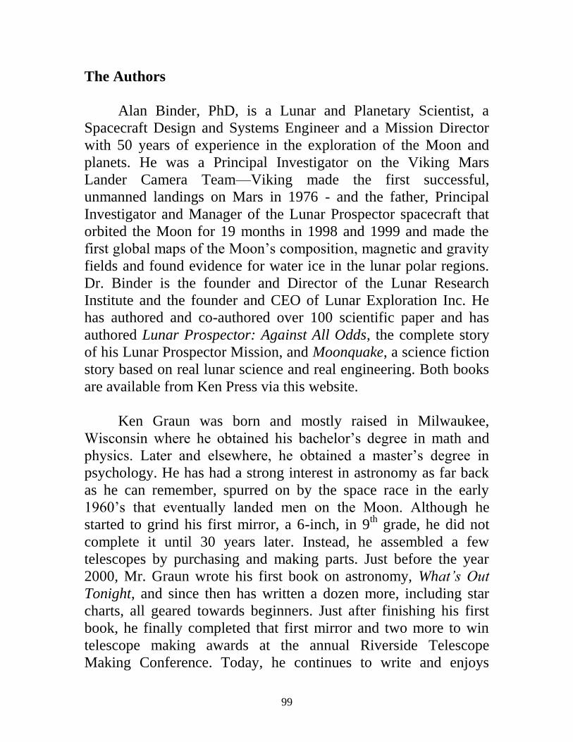
99
The Authors
Alan Binder, PhD, is a Lunar and Planetary Scientist, a
Spacecraft Design and Systems Engineer and a Mission Director
with 50 years of experience in the exploration of the Moon and
planets. He was a Principal Investigator on the Viking Mars
Lander Camera Team—Viking made the first successful,
unmanned landings on Mars in 1976 - and the father, Principal
Investigator and Manager of the Lunar Prospector spacecraft that
orbited the Moon for 19 months in 1998 and 1999 and made the
first global maps of the Moon’s composition, magnetic and gravity
fields and found evidence for water ice in the lunar polar regions.
Dr. Binder is the founder and Director of the Lunar Research
Institute and the founder and CEO of Lunar Exploration Inc. He
has authored and co-authored over 100 scientific paper and has
authored Lunar Prospector: Against All Odds, the complete story
of his Lunar Prospector Mission, and Moonquake, a science fiction
story based on real lunar science and real engineering. Both books
are available from Ken Press via this website.
Ken Graun was born and mostly raised in Milwaukee,
Wisconsin where he obtained his bachelor’s degree in math and
physics. Later and elsewhere, he obtained a master’s degree in
psychology. He has had a strong interest in astronomy as far back
as he can remember, spurred on by the space race in the early
1960’s that eventually landed men on the Moon. Although he
started to grind his first mirror, a 6-inch, in 9th
grade, he did not
complete it until 30 years later. Instead, he assembled a few
telescopes by purchasing and making parts. Just before the year
2000, Mr. Graun wrote his first book on astronomy, What’s Out
Tonight, and since then has written a dozen more, including star
charts, all geared towards beginners. Just after finishing his first
book, he finally completed that first mirror and two more to win
telescope making awards at the annual Riverside Telescope
Making Conference. Today, he continues to write and enjoys

100
teaching math and physics at community colleges. But, one of his
favorite things is to show the night sky to those wanting to learn.
We met about ten years ago (2004), when Ken agreed to
publish Alan’s book, Lunar Prospector: Against All Odds, (and a
few years later Moonquake) and since then have been the best of
friends. We have spent countless hours observing and discussing
telescopes, astronomy, lunar and planetary science, the space
program, physics, science in general, politics, etc.—essentially
most every topic in the universe at large. It is through our mutual
interests in telescope making and astronomy that we decided to
write this manual, make the accompanying video and provide the
kits to encourage you to start making telescopes and observing our
fascinating universe.

101
Conclusions As indicated in Part I, we have written this manual and make the video and kits for anyone, from youngsters to adults of any age, who has a serious interest in telescope making and astronomy, but does not know how to get started. As indicated on page 16, the $20.00 we charge for each kit is much less that the cost of the materials provided in the kit and does not take into account the fact that we spend several hours making the wooden parts for the telescope and cutting the six glass blanks for the three lenses included in each kit. As such, we ask that you purchase a kit only if you have a serious interest in making the simple, astronomical telescope we describe and are willing to spend 8 to 10 hours grinding and polishing the objective lens and 4 to 6 hours grinding and polishing each of the eyepiece lenses, plus the several hours you will spend making the telescope tube and the telescope mount and tripod. If you do, we firmly believe that the 25 to 30 hours required to make your telescope, the lessons learned while making it and all that you will learn using your astronomical telescope are well worth the effort. Thus, we encourage you to order a kit and start the journey. And please note that we will support you as much as possible in your endeavor to complete the telescope. Thus, if you have questions or are having difficulty with any part of the topics covered in this manual, please feel free to contact either of us via the following email addresses: [email protected] [email protected]

102
Also, we are interested in any comments—good and bad—you might have about A) the experiences you had in making your telescope, B) the experiences you are having observing with your telescope and C) how many of the objects we have listed in Appendix A you have been able to observe. Finally, we thank Alex Miramontez, Vice-President of the Glaz-Tech company here in Tucson for providing us, gratis, with the plate glass we use to make the blanks and tools for the lenses you made using this manual, thereby helping us to keep the cost of the kit as low as possible.