A Shielded Resistor for voltage transformer...
27
S 516 A SHIELDED RESISTOR FOR VOLTAGE TRANS- FORMER TESTING By Francis B. Silsbee ABSTRACT Voltage transformers are widely used in measuring electric power and energy, and since their accuracy enters directly into the charges for this commodity the need for testing them is apparent. This paper describes the equipment and method used at the Bureau of Standards for testing such transformers over the range from 220 to 30,000 volts. The null method employed is capable of a precision of 0.01 per cent in ratio and 0.3 minute in phase angle at 60 cycles. The 500,000-ohm working resistor connected across the high voltage is subdivided into sections of 20,000 ohms, each of which is inclosed in a metal shield which in turn is connected to a tap at the proper point of an auxiliary guard circuit. The charging currents from these shields to ground, therefore, flow in the guard circuit only and do not directly affect the working circuit. A theoretical dis- cussion of subdivided shielded resistors of this type and also of the uniformly shielded type shows that the error arising from capacitaiice to ground, though greatly reduced by the use of the guard circuit, is not completely eliminated and increases in importance very rapidly as the working voltage of the resistor is increased. CONTENTS Page I. Introduction 489 II. Description of apparatus 491 III. Procedure 493 IV. Experimental work 494 V. Theoretical relations 499 VI. Conclusions 512 VII. Notation 513 I. INTRODUCTION The steady growth in the size and operating voltage of electric power systems and the constant rise in the standards of accuracy required in electrical measurements have directed more and more attention to the accuracy of the voltage transformers which are used in practically all commercially important measurements of electrical energy. The errors introduced into power measurements by voltage transformers of good design are small, but cases often arise in which they can not be neglected, and the transformer must be tested to determine accurately the ratio of primary to secondary voltage and the phase angle between these vector quantities. 489
Transcript of A Shielded Resistor for voltage transformer...

S 516
A SHIELDED RESISTOR FOR VOLTAGE TRANS-FORMER TESTING
By Francis B. Silsbee
ABSTRACT
Voltage transformers are widely used in measuring electric power and energy,
and since their accuracy enters directly into the charges for this commoditythe need for testing them is apparent. This paper describes the equipmentand method used at the Bureau of Standards for testing such transformers
over the range from 220 to 30,000 volts. The null method employed is capable
of a precision of 0.01 per cent in ratio and 0.3 minute in phase angle at 60 cycles.
The 500,000-ohm working resistor connected across the high voltage is subdivided
into sections of 20,000 ohms, each of which is inclosed in a metal shield whichin turn is connected to a tap at the proper point of an auxiliary guard circuit.
The charging currents from these shields to ground, therefore, flow in the guard
circuit only and do not directly affect the working circuit. A theoretical dis-
cussion of subdivided shielded resistors of this type and also of the uniformly
shielded type shows that the error arising from capacitaiice to ground, thoughgreatly reduced by the use of the guard circuit, is not completely eliminated andincreases in importance very rapidly as the working voltage of the resistor is
increased.
CONTENTSPage
I. Introduction 489
II. Description of apparatus 491
III. Procedure 493
IV. Experimental work 494
V. Theoretical relations 499
VI. Conclusions 512
VII. Notation 513
I. INTRODUCTION
The steady growth in the size and operating voltage of electric
power systems and the constant rise in the standards of accuracy
required in electrical measurements have directed more and moreattention to the accuracy of the voltage transformers which are used
in practically all commercially important measurements of electrical
energy. The errors introduced into power measurements by voltage
transformers of good design are small, but cases often arise in which
they can not be neglected, and the transformer must be tested to
determine accurately the ratio of primary to secondary voltage and
the phase angle between these vector quantities.
489

490 Scientific Papers of the Bureau of Staindards [ voi. go
Relative methods of test, in which the transformer under test is
compared with a standard transformer of the same nominal ratio, of
which the true ratio and phase angle are known, are quite simple andeasy to apply.^ Convenient portable apparatus ^ is on the market
for making such tests and the precision with which such comparisons
can be made is quite high.
Primary testing laboratories, such as the United States Bureau of
Standards, are, however, called upon to test these standard trans-
formers for others to use and must, therefore, apply some absolute
method of measurement. The purpose of the present paper is to
describe the equipment which has been developed at the Bureau of
Standards for this purpose, and which has been in satisfactory
operation there for the past seven years. Some space will also be
devoted to the general theory of apparatus of this type to show its
possibilities and limitations, and to indicate other possible applications
as a guide to other laboratory workers.
Since both ratio and phase angle are physically dimensionless
being merely ratios of the in-phase and quadrature components,
respectively, of a pair of alternating vector quantities, no measure-
ment of any electrical quantity in international units is essential.
The test, therefore, readily lends itself to null methods in which the
secondary voltage is opposed to a known fraction of the primary
voltage. This fraction (of known vector value) can be obtained byconnecting two impedances in series across the primary terminals of
the transformer. While these impedances might conceivably be
resistors, inductors, or condensers, the only type which has thus
far been used in precise measurements is that in which resistance
predominates and the current through the two impedances is sub-
stantially in phase with the primary voltage. The phase angle of
the voltage transformer may be compensated for by suitably as-
sociating either a condenser or a self or mutual inductor with the low-
side impedance.
Somewhat similar conditions are met with in other measurements
at high voltages as, for example, in the measurement of the powerloss in condensers or cables. If this measurement is made by watt-
meter or bridge methods an accurately known impedance is needed
to serve either as a series resistor for the wattmeter or as one arm of
the bridge, and resistors of the type here described may be useful.
In constructing resistance coUs of moderate range (1 to 1,000 ohms)
it is customary to wind the wire bifilarly on spools. In coils of low
value, 1 to 10 ohms, the magnetic field close to the wires is not
entirely eliminated and gives rise to a small but appreciable residual
1 H. B. Brooks, B. S. Sci. Paper No. 217; P. G. Agnew, B. S., Sci. Paper No. 233.
' For example, the " Comparator voltmeter" of the Weston Electrical Instrument Corp., and the " Poten-
tial transformer testing set" of the Leeds & Northrup Co.

Silsbee] A Shielded Resistor 491
inductance. There is, however, also a certain electrostatic capaci-
tance between adjacent turns and adjacent layers which tends to
neutralize this inductive effect and in 100-ohm coils this capacitance
just about balances the effect of the self-inductance and the coil is
very closely nonreactive. In coils of 1,000 ohms, and higher the
capacitance effects predominate. The resulting phase displacement
in 1,000-ohm coils is usually only about 0.1' at 60 cycles and bysuitable construction ^ it can be kept negligible even in 10,000-ohm
coils. In voltage transformer testing, however, resistances ranging
from 20,000 to 500,000 ohms are involved and capacitance presents
a more serious problem. Winding the resistance wire on thin mica
cards reduces the capacitance trouble by separating the ends of the
wire, which differ most in potential, without introducing any appre-
ciable magnetic field. Such cards, however, have capacitance to
their neighbors and to surrounding objects so that in the construction
of resistors for high voltage the combination of even nonreactive
units may result in a circuit having an appreciable phase angle.
Furthermore, any capacitance to other objects in the laboratory will
m.ake the phase angle of the circuit change with changes in location
or potential of such objects, so that consistent results may be expected
only with equipment in which the measuring circuit is almost com-
pletely shielded by metal surfaces maintained at definite potentials.^
Because of these considerations the equipment used at the Bureau
of Standards for voltage transformer testing is constructed with its
working circuit entirely shielded. It is subdivided into a number of
sections and the shield surrounding each section is connected to the
proper point of a "guard" circuit which is connected at its ends in
parallel with the working circuit. Resistors of this tjTpe have been
described by Orlich,^ Kouwenhoven,® and Hiecke^ and seem to be
the most desirable type of impedance for the range between 20,000
and 500,000 ohms.
II. DESCRIPTION OF APPARATUS
The working circuit has a total resistance of about 520,000 ohmsand is formed of 27 units. Two of these have resistances of 10,000
ohms each, while the others have 20,000 ohms each. The manganinresistance wire is wound on cards of built-up mica 14 by 5.6 cm.
The resistance of each card is about 1,250 ohms and each unit (except
the first two) contains 16 cards. Each set of cards is himg vertically
in its shield on two glass rods which pass through holes in the upper
3 H. L. Curtis and F. W. Grover, B. S. Soi. Papers Nos. 175 and 177; 1911.
* Campbell, Q. A., The shielded balance, Elect. Wld., 43, p. 647; 1904.
5 Orlich, E., and Schultze, H., Archiv. fur Elek., 1, pp. 1, 88, 232; 1912.
« Kouwenhoven, W. B., Diss. Elektroteeh. Institute Karlsruhe, 3; 1913.
» Hiecke, R., Electrotech. u. Masch., 38, p. 505; 1915.

492 Scientific Papers of the Bureau of Standards [Vol. to
corners of the cards and rest in notches in the side of the shields.
The shields are formed by brass boxes 20 by 20 by 13 cm identified
by numbers in Figure 1. The boxes are filled with oU which serves
to decrease the temperature rise of the working circuit particularly
on short overloads. The terminals of the resistor are brought out
through fluted hard-rubber bushings to binding posts on the outside
of the box.
The guard circuit has the same resistance as the working circuit
and is made of cards of the same kind which, however, are not inclosed
but are open to the air. The guard cards are hung on glass rods on
Fig. 2.
—
Circuits used in the precise testing of voltage transformers for ratio andphase angle
racks, each of which corresponds to two adjacent boxes of the working
circuit. A tap at the center of each rack has the same potential as
the lead joining the two boxes. Two other taps at the one-fom'th
and three-fourth points have the same potential as the mid-points of
the two working circuit boxes and each of these latter taps is connected
permanently to the corresponding shield.
The equipment is mounted as shown in Figure 1 on a rack madeof wooden bars spaced by porcelain bus-bar supports. Four boxes
and the corresponding two guard racks rest on each shelf.
The connections used for voltage transformer testing are shownschematically in Figure 2. Here W and G are the working and

Scientific Papers of the Bureau of Standards, Vol. 20
Fig. 1.
—
General view of shielded resistor

siisbee] A Shielded Resistor 493
guard circuits, respectively. When switch T is thrown to the left
they are connected in parallel with the primary P of the transformer
under test. At A are shown two idle units which are left in position
on the rack, but are disconnected from the circuit when not in use.
The voltage at the terminals of the secondary S of the transformer
under test is opposed to the drop on the resistor R^. This consists
of a 6-decade resistance box, the 1,000-ohm units of which consist
of three separate "Curtis type" coils wound on porcelain spools.
In most work the number of units is chosen to give a current of
about 0.05 amperes in both the working and guard circuits andi?2 is about 2,000 ohms.
The mutual inductance M, the primary of which is in series with
the working circuit, serves to introduce into the circuit of the ac.
galvanometer, G^ a small emf in quadrature with the drop in R2,
thus compensating for the phase angle of the transformer under
test. The inductor L ' in the guard circuit has the same value as the
self-inductance of the primary L of the mutual inductor. All parts
of the. wiring, galvanometer support, etc., are shielded by lead
sheaths or metal plates which are connected to suitable points on the
guard circuit.
III. PROCEDURE
The procedure in testing a voltage transformer with this apparatus
is to connect between T and ground as many units as are needed to
give a current of about 0.05 ampere. Switch Tis closed to the left
and the high-voltage circuit is energized. The frequency, the second-
ary voltage, and the burden B are adjusted to the desired values.
A prehminary balance is made by adjusting R^ and M using the
ac. galvanometer G-^ as a detector. This galvanometer is then
shifted by suitable switches to the position shown at G^ by the
dotted hues and R-^ and L' in the guard circuit are adjusted for a
balance. The galvanometer is again connected at G^ and the final
balance of R^ and M is made. The high-voltage supply is then cut
off, switch T is immediately thrown to the right and the dc. galvano-
meter 6^3 is used to balance the Wheatstone bridge formed by the
arms TF, R^, Q, and D. Q is a standard resistor of 10, 100, or 1,000
ohms, and D is a precision decade resistor. The PR loss in the
working circuit at 30,000 volts amounts to about 1.8 kw and the
temperature rise is sufficient to cause changes in the resistance of Wwhich somewhat exceed the hmit of precision of 0.01 per cent
which is aimed at. By means of this dc. bridge measurement, the
current for which is supphed by a 20-volt battery C, any appreciable
error caused by the heating of W or R^ by the working current is
ehminated. It may be noted that the guard wire functions on the
dc. balance to prevent leakage errors.
494 Sdentific Papers of th^ Bureau of Standards [ voi. to
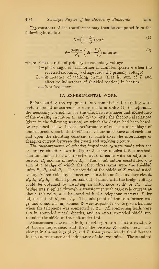
Th£ constants of the transformer may then be computed from the
following formulas
:
o
'8 to / nr_iw\^ 3438 w/,, L^\ . ^ (2)0=—D— ( M-^^ ) minutes
where -A'=true ratio of primary to secondary voltage
= phase angle of transformer in minutes (positive when the
reversed secondary voltage leads the primary voltage)
iw = inductance of working circuit (that is, siun of L and
effective inductance of shielded section) in henries
oj = 2- X frequency
IV. EXPERIMENTAL WORKBefore putting the equipment into commission for testing work
certain special measurements were made in order (1) to determine
the necessary corrections for the effective resistance and inductance
of the working circuit on ac. and (2) to verify the theoretical relations
(given in the following section) on which the design had been based.
As explained below, the ac. performance of such an assemblage of
units depends upon both the effective vector impedance Zt of each imit
and upon the shunting constant st which fixes the interchange of
charging current between the guard and working circuits.
The measurements of effective impedance 2k were made with the
ac. bridge circuit shown in Figure 3, using a substitution method.
The unit under test was inserted at J? in series with an adjustable
resistor R^ and an inductor L^. This combination constituted one
arm of a bridge of which the other three arms were the shielded
units R^, i?2, and R^. The potential of the shield oiX was adjusted
to any desired value by connecting it to a tap on the auxiliary circuit
i?,, R., i?e, ^5. Shield potentials out of phase with the bridge voltage
could be obtained by inserting an inductance at R- or R^. Thebridge was suppUed through a transformer with 900-cycle current at
about 150 volts, and balanced with the telephone receiver T^ byadjustment of R^ and L^. The mid-point of the transformer wasgrounded and the impedances Z' were adjusted so as to give a balance
when the telephone was connected at T,. All connecting leads were
run in grounded metal sheaths, and an outer grounded shield sur-
roimded the shield of the unit under test.
Measurements were made by inserting in arm 4 first a resistor Sof known impedance, and then the resistor X under test. Thechange in the settings of R^ and L^ then gave directly the difference
in the ac. resistance and inductance of the two xmits. The standard

Silibee] A Shielded Resistor 495
available for this work was a 10,000-oliin coil kindly loaned by Dr.
H. L. Curtis, who had previously compared it carefully with a 10,000-
ohm circuit formed by two long straight parallel manganin wires the
inductance of which could be computed from their dimensions. Withthis as a basis and with R^ =10,000 ohms, values were obtained on (a)
10,000-ohm imit No. 1, (b) 10,000-ohm unit No. 2^ and (c) on the
combination of two 20,000-ohm units Nos. 11 and 24 in parallel.
i?3 was then changed to 20,000 ohms and comparisons again madeamong (a) unit No. 11, (b) imit No. 24, and (c) imits Nos. 1 and 2
in series. This procedure gave two independent values for the
Z*
—X
—
i?r
W»/WWWVWWAA-
FiG. 3.
—
Bridge circuit used in measuring effective impedance of individual units
effective inductances of the 20,000-ohm iinits which were found to
agree to 0.6 millihenries.
The other 20,000-ohm \mits were then compared with No. 24 andall were found to have very nearly the same inductance. Measure-
ments were also made of the effect of changes in shield potential pkon the impedance z^. These confirmed the approximate relations
which are theoretically predicted by equation (42) below.
(1). The effective resistance of a unit is a linear function of the
quadrature component of pt.
(2) . The effective inductance of a unit is a linear function of the
real component of pk-
8 Later Dr. C. Moon kindly compared this unit directly against another parallel-wire standard whichhe had set up and obtained concordant results.
66928°—26t 2

496 Scientific Papers of the Bureau of Standards [ Vol. SO
(3) . The slopes of these lines are (for symmetrical constructions)
—H— and -^> respectively. Where p^ is defined as the excess of
the potential of the shield over the potential of the ground end of
the unit, expressed in terms of the voltage across the unit.
Measurements on s^, the factor which gives the charging current
to the shield in terms of the current through the resistor, were madewith the circuit shown in Figure 4. As beforeX is the unit under
test. For values of Pk=}/2, -^i and R^ were 20,000 ohms and R^
and i?5 were 10,000 ohm units, i?, ^^^ ^'2 were small adjustable
resistors. Other values of pk could be obtained by suitable changes
in the various resistances.
nyfrf^mymwpppnmr^
I^VWWyW/vQ rMA/MWW: ^Af<AMMAAAr-
Fig. 4.
—
Circuit used in measuring shunting, constant s^ of individual units
Condenser C2 was inserted as a ballast and a zero setting wasmade with switch S open. The change Ad in C^ when S was closed
gave a measure of s^ as shown by the following approximate equation:
R -\-R -\-XSi=juACiR'2 a ^*ii +^Ji' +R approximately by (3)
The results obtained on several units confirmed the approximate
theoretical relations (equation (43)) as follows:
(1). The imaginary component of St is a linear function of the real
component of pk-
(2). The imaginary component of s^ is equal to oirCl^ — pk)-
As will be seen from relation (2) Sk becomes zero if Pk=2 when the
unit is symmetrical. This fact makes it quite desirable to operate
the circuit with this value of p^.
The validity of the equations given below connecting the constants
of the series combination of units with those of a single unit was
also tested by connecting the two 10,000 ohm units in series and
directly measuring the impedance of the combination for various
values of the shield potentials. The results are given in Table 1.

Silibee] A Shielded Resistor
Table 1
497
Pl Pa ii Xj Sicomp. obs.
0.0.2.5.81.0.0
0.0.2.5.8
1.01.0
+1.0+ .3- .3- .9-1.4+1.0
+1.0+ .3- .3- .9-1.4-1.4
+13. ixifr-y+7.90.0
-7.9-13.1+13.1
+4.3+2.0- .6-3.2-5.1+1.7
+4.0+2.1- .6-3.5-5.3+1.8
Pi and P2 ^i"6 the respective values of p^ at which units No. 1
and 2, respectively, were operating. L^ and L^ are the values of
inductance (in millihemys) and s^ is the value of charging current
ratio found experimentally on unit No. 1 at those particular values
of p. The sixth column gives the effective inductance of the com-
bination as computed from equation (49) while the last column
gives the effective inductance actually observed.
Further tests were made by deliberately making various irausual
adjustments of the guard system and noting the resulting change
in the apparent phase angle and ratio of the transformer which wasbeing tested. Since the transformer was actually unaffected bythese changes the observed differences are the result of the changes
thus introduced into the measuring network. A comparison of the
observed differences in the case of a 25,000-volt transformer with
those computed by the theoretical equations given below is contained
in Table 2.
Table 2
Maladjustment
Shift in phaseangle
ObservedCom-puted
Shift in ratiofactor
ObservedCom-puted
SOD ohms added to ground side of guard circuit
2,000 ohms added to ground side of guard circuit
1 henry plus 98 ohms added to ground side of guard circuit
Shield No. 12 connected to tap No. 13
Shield No. 3 connected to tap No. 4
Pk=l for all boxes _ - -
Minutes1.24.9+.2-1.2-2.0-6.2
Minutes1.054.2-.2-.95-1.5-7.
O.OOO0J. OOOI3.00023.OOOO3.OOOOj. 00015
0.00022
The agreement between computed and observed values given in
the two preceding tables, while closer than 0.8' and hence satisfactory,
does not suffice to prove the validity of the method since only the
effects of changes in p-^ are there considered. The question of
whether or not the guard system in normal adjustment does actually
give the intended values of p^ remains unanswered. The resistances
of the several sections of the guard wire can be easily adjusted to
the nominally correct values, but the capacitance from the shields
and from the guard wire itself to ground and to surrounding objects
introduces a disturbing influence of indeterminate magnitude, as
498 Sdentijic Papers of the Bureau of Standards [voi.to
will be shown in the following section. The error introduced into
the working chcuit by a given disturbance in the shield potentials is
usually much less than the error which the same capacitance wouldproduce in an unshielded resistor. Nevertheless this error increases
rapidly with the capacitance and resistance of the circuits, and anexperimental check on it is very deshable.
At least four possible ways of getting at this source of error oflfer
themselves. The first of these is dehberately to increase the error
by increasing the capacitance involved. This can be done either byconnecting additional dummy shields to the tap points of the guard
cii'cuit or more simply by placing a metal plate near the guard circuit
and connecting it to ground or to the hve terminal of the circuit. In
the apparatus here described the presence of a plate which must have
increased the capacitance manyfold changed the impedance of the
working circuit by less than 2 parts in 10,000.
The second test is dehberately to decrease the disturbance in the
shield potentials by reinforcing it when possible by direct connec-
tion to the step-up transformer. In the present case the transformer
secondary had four sections connected in series, and tests (by substi-
tution) showed that these sections were very closely identical. Whenconnections were made from the thi'ee intermediate taps to three
points spaced equidistantly along the resistance of the guard circuit,
the working circuit was affected by less than 0.5' in phase angle and
thirty millionths in resistance.
The third and most dii'ect test for the acciu'acy of the guard poten-
tials is to measure the difference in potential between the guard and
working circuits at various points along their length. This can be
done with an accm'acy of a few volts and x^ithout seriously disturbing
the potential distribution by using a small gold-leaf electroscope. In
the equipment here described the observed potential difference had a
maximiim value of 24 volts at a point about two-thirds of the total
resistance above ground. The total apphed voltage was 24,000 volts
in this case. Such a disturbance of the potential distribution could
be caused by a uniformly distributed capacitance to ground of about
100 micromicrofarads, and introduces an error of only SO parts per
milhon in the resistance of the working chcuit.
A fourth but inferior basis for estimating guard chcuit errors can
be obtained by observing the ac. impedance of the guard circuit
itseh. This is most readily done by comparison with the working
circuit, using the ac. galvanometer connected at G2 in Figure 2.
The observed impedance is the result of the effects on the guard
resistor of two classes of capacitance (a) the capacitance between
adjacent shields, and (b) the capacitance from shield to ground.
The former has very httle effect on the potential distribution, but
tends to make the current thi'ough the guard circuit lead the voltage.

Silsbee] A SJiielded Resistor 499
The latter capacitance shunts current off to ground and makes the
delivered current lag. The amount of effect (a) can be estimated
from measurements of the capacitance between adjacent boxes
and the residual phase angle of the guard circuit after this has been
allowed for serves to give an estimate of the capacitance to ground.
Table 3 gives a general idea of the precision with which measure-
ments made with this equipment may be duplicated. The data
tabulated are the ratio and phase angle at no load, 60 cycles, on three
ranges of a transformer which had its primary winding formed byfour very closely equal coils, and hence should have shown very
nearly identical values for ratio-factor and phase angle on all ranges.
Table 3
Primary range ot transformerin volts
25,00025,00025,00012,50012,5006,250-6,250-
Numberof
resistor
units
Ratiofactor
Phaseangle
used
Minutes24 1.00013 -1.524 1.00021 -1.324 ].0002i -1.424 l.OOOle -1.112 l.OOOlo -1.212 1.00008 -.86 1.00009 -1.0
Some of the observed difl'erences may be the residt of capacitance
effects in the transformer itself.
V. THEORETICAL RELATIONS
To gain a more definite idea of these capacitance effects men-tioned above, let us consider some particular cases as foUows.
If an inductive resistance R has a capacitance C across its termi-
nals, the impedance of the circuit thus formed is given by:
R jw{L-CR')(4)l+w^C^R"^ 1+u^C^R^
if o)^ LC is small compared to 1. Hence the ac. resistance is given by
Rac =R (l — u^C^R^) approximately (5)
and the phase angle is
d = taiir'o}(^-CR^ (6)
or if L is small
e = tan~i ( - COOR) radians (7)
These relations show that for the case of a single circuit the phase
angle is nearly proportional to the frequency, the capacitance and
the resistance, and that the fractional error in resistance is of the

500 Scientific Papers of the Bureau of Standards [Vol. go
same order of magnitude as the square of the phase angle (in radians).
It is also evident that the current leads the applied voltage and that
the current is the same at the two ends of the working circuit.
Let us next consider a nonreactive resistor R which has a condenser
C connected between its mid-point and ground (fig. 5) . The current
in the lower part of the ckcuit at B now differs from that at A and the
impedance of the circuit requires a more specific definition than
merely ''the vector quotient of applied voltage divided by the re-
sidting current." If this resistor is to be used on the primary side of an
equipment for voltage transformer testing, we are primarily interested
in the current which it delivers at the grounded end B, and will, there-
fore, define the impedance in this and similar cases as ''the vector
quotient of applied voltage divided by the current delivered at the
terminal nearest to ground potential." This
works out to be approximately
,=^=,(,,,^) (8)
.L>_L 1Fig. 5.
—
Resistor withcapacitance to ground
concentrated at center
and we see that the delivered current lags
behind the applied voltage; that is, the circuit
has an apparent positive inductance, although
no magnetic field has been considered.
If we define Kassb quantity such that at anypoint of the circuit it is equal to the quotient
of the resistance from that point to groimd
divided by the total resistance, then the
potential V at any point along the wire is
given byF= Vn E (9)
when the condenser is absent. If we let
a'==j<^R G (10)
then, with the condenser in place, we have for points below the tap
i-f(11)
and for points above the tap
1 +a'
(12)

siishee] A Shielded Resistor 501
In practice the stray capacitances are not usually concentrated at
certain points, but distributed along the length of the circuit. There-
fore, let us next take the case of a circuit of resistance B which has its
total capacitance to ground distributed uniformly along it, so that
any section of resistance i? J jK^ has a capacitance G dK to ground and
potential V (K) above ground.
This system is, of course, a special case of a transmission line. Thecurrent passing off to ground from any element is
dI==joiVGdK (13)
and the drop in voltage in the element is
dV=IRdK (14)
combining these equations gives
d'VdK-
-a?V=Q (15)
as the dijfferential equation for V in terms of K, when d'=joiCR
The solution is
^ Vn sinh aK ,^„.V= ^-r (16)smh a
The current at the base (^=0) is
T —^/^^\ _ <^^n/cosh aK\ ^ Vn a , „.
^°~R\dK)~ R \ sinh a )~R^mh a^^''
and the apparent impedance is
^^^V R^(18)
to "
The hyperbolic sine may be expanded in a power series giving
(19)
Z. = 5(l + ,^+ ,^--)
= S(l +^-g— ^20----^
It will be noted that this differs from the preceding case which
assumed a lumped capacitance (equation (8)) in the numercial coeffi-
cient of the jwCR term and in the appearance of a term of higher
order corresponding to a change in resistance.
Since in almost any practical form of construction an increase in
R is accompanied by an increase in C the phase angle of the systemwill increase nearly in proportion to R^. Thus for a 10,000-ohm
resistor for which (7=20 micromicrofarads the phase angle is only

502 Scientific Papers of the Bureau of Standards ivoi.so
1
0.04', but for 1 megohm, with (7=212X10-'= the angle becomes46', which is actually larger than that of many of the voltage trans-
formers which the equipment might be required to test. The direct
reduction of these errors by using low values of R requires at high
voltages the dissipation of inconveniently large amounts of power.
This is unsatisfactory both because of temperature erroi-s andbecause the large areas required for heat dissipation increase C andtend to offset the gain resulting from the reduction in R.
The alternative remedy is that described above of subdividing
the resistor and surrounding each section by a shield which is main-
tained at a definite potential which approximates that of the resistor
section within it.
In what might be termed the ideal form
of such a shielded resistor the subdivision
may be considered as carried to the limit
of having each differential element of the
wire shielded by a corresponding element
of the guard wire.
The equivalent circuits for such a struct-
ure are indicated in Figure 6. Here i?w and
Rg are the total resistances of the '"work-
ing" and ''guard" circuits, respectively, and
Cg is the total capacitance from the guard
circuit to gi'oimd (assumed uniformly dis-
tributed) Cw is the capacitance (also
assumed uniform) between the working
circuit and the shields which cover it.
As before we have for any infinitesimal
section of the working circuit
dI^ = jc^C^{V^-Vg)dK (20)
dV^^R^I^K (21)
Fig. 6.
—
Uniformly shielded
resistor with uniformly dis-
trib uted capacitance to
ground
and for each element of the guard circuit
dh = i" Cg VgdK+ jcoa ( T g V^)dKdV^ =R^LdK
Combining these gives
d*V, a"d'V
fe=r^=o
(22)
(23)
(24)dK* " dK'
as the differential equation for Tv, the potential of any point of the
working circuit. Here
a'2 = jo: {CgRg + CVi?w + C^Rg)
h^ = ur CyfCgR^Rg
The solution of this equation for the case of V^ = Vg = Vn at
and Fw=V^e = at Z=0 is
(25)
(26)
A=l
jr Vn r,. sinh_
^-=(l32^)L(l-'?)^Shsinh mgjf sinh rn
rris
— Vsinh m-1 (27)

siisbee] A Shielded Resistor 503
rj is a constant of the circuit defined by
1-^1 +a'" (28)
'^-2
and mi and ms are defined by
m^ = a'Ml-»7) (29)
m\^a'^-n (30)
The corresponding solution for the potential Vg of the guard wire is
where p is defined by
'°= (l+f'+l^') (32)
and the effective impedance of the working circuit is
i?w(l-277)^ow (l-r?)m3 mir? (33)
sinh ma sinh mi
While this rigorous expression appears rather formidable, an exnan-
sion in power series reduces it to
C7 31
For small values of C^ (the capacitance which couples the twocircuits together) a'^ becomes approximately joiCgRg and h^ and 17
become very small. The second term (equation (33)) in the denomi-
nator drops out and the first term approaches unity so that Zowapproaches Ry, as 0^ is decreased.
On the other hand if (7^ is made large compared with Cg, 17 again
becomes smaU and mi becomes large so that the second term again
p J? 7?
drops out. m^', however, approaches the value j co Jf_ ^ so that
^vr I ^gZow approaches the value given by
7 _p smh j CO CgRp
which is the same result as indicated by equation (18) for a single
resistor of resistance Sp, where Rp= p "^ p is the resistance of Ry,
and i?g connected in parallel.

504 Scientific Papers of the Bureau of Standards [ voi. to
These results, therefore, indicate that if the coupling between the
working and guard circuits is small enough the performance of the
working circuit will be perfect even though the capacitance of the
shields to ground may seriously distort the potential distribution in
the guard. As the coupling is made closer, however, the disturb-
ing capacitance begins to affect the working circuit also and in the
limit of very close coupling the working circuit has the same potential
distribution as the guard circuit.
To estimate the magnitude of these capacitance effects let us workout a few numerical cases.
For a single circuit, equivalent to that described above, to be used
on 25,000 volts, with a woi-king current of 0.05 amperes the heat
dissipated would be 1.25 kw. and the resistance 500,000 ohms. These
values are reasonable for laboratory work, and such a structure might
be assumed to have a total capacitance to ground of 106 micromicro-
farads. For this case at 60-cycles
a^ =0.02y
^'^^=1 + 0.00337-3.3 XlO-«
hence the phase shift amounts to 0.0033 radians or 11.3 minutes of
arc, while the change in effective resistance is only 3 parts per
million.»
If a second circuit were connected directly in parallel with the first
and the two used as a single ch'cuit with no shielding, the resistance
might be cut in half without greatly increasing the capacitance and
the phase error would be reduced to 5.7'.
If, on the other hand, the first circuit is used to guard the second
and only the latter is used as the working circuit the performance is
greatly improved. If the capacitance C^ between the guard and
working circuits could be kept down to the same value of 106
micromicrofarads, we would have
m,' =0.0524?
ms" =0.0076;
and Zow =i?w (1 - 7.7 X 10-«).
That is, the phase-angle error would be negligible and the resistance
error would be less than 8 parts per million.
It is, however, difficult to keep the value of C^ so small, but if it
was equal to 1,060 micromicrofarads, which is about the value in the
present equipment; that is, 10 times the capacitance from the guard
to groimd, the resistance error would still be only 80 parts per million
and the phase angle error less than 0.1'.
If the coupling capacitance is made still greater, however, say
10,600 micromicrofarads, the resistance error mounts to 800 parts
per million and the phase angle to over 1 minute.

siisbee] A SMeldcd Resistor 505
The errors also raount rapidly with increase in the voltage rating
and hence in the resistance of the circuits. For 100,000 volts with
the same current the resistance needed is 2,000,000 ohms, and for a
single circuit, even if the capacitance to ground were only 212 micromi-
crofarads, the phase angle would be 92' and the error in resistance
210 parts per million.
With the shielded system of 2,000,000 ohms resistance, for a coup-
ling capacitance 10 times the ground capacitance, the phase angle
error would still be 6' and the resistance error 5,000 millionths. Theshielding principle is thus seen to be applicable only within very
definite limits, though it may be very effective within these limits.
While the uniformly guarded circuit discussed above lends itself
to mathematical handling, the actual physical construction of such
a circuit is rather difficult, and it is usually more convenient to con-
struct a system in which the working circuit is divided into a numberof units each of which is inclosed in a metal shield. Each shield is
connected to a suitable point on the guard circuit, and the guard
and working circuit are connected together at each end. When the
number of sections is large the performance of such a shielded re-
sistor will, of course, approach closely that of a uniformly guarded
system having the same total resistance and capacitances, and the
more general conclusions arrived at in the preceding paragraphs are
appHcable in any case. The inciosure within a single shield of parts
of the working circuit which are not all at the same potential does,
however, introduce a further complication which needs considera-
tion in order that the errors introduced thereby may be evaluated.
It should be noted that these capacitance effects are determinate
and can be m^easured and corrected for, while those arising from
capacitance to ground are indeterminate and remain as sources of
error.
Each of the units of which the total resistor is built up may be
termed a "three-terminal impedance." Two terminals, ^ and B,
Figure 7, connect to the resistor rt, while the third terminal C con-
nects to the shield which has a certain capacitance to the various
parts of rt. For the Icth unit from the groimd end of the system wemay denote the potential of the working circuit terminals with re-
spect to ground by V^ and Fk_i (the former being the greater) , andthe potential of the shield by Fk'. The currents flowing through
the terminals may similarly be represented by /t, /k_i, and I\,
respectively, and are related by the equation
/k = /k-i+/'k (36)

506 Scientific Papers of the Bureau of StandardsI Vol. to
Following the above notation and the definition already given for
similar networks (equation (8)) we may define the impedance 2^ of
the ktlh unit by
3k=-S^
—
— =Y^ (37)
This single quantity does not, in general, completely describe the
function of the unit, since, in addition to delivering to the next unit
below a ciurent /k_i, it also delivers to the guard circuit the current
I\. We may, therefore, introduce the additional vector quantity
Sk defined by the relation
(38)Sk =
7k-i
^ t-
FiG. 7.
—
Scheme of notation of potentials and currents in a single unit
For any given potential distribution the two quantities Sk and s^
will completely describe the electrical behavior of the IctJi unit. Both
of these quantities, however, depend upon the relative potential of
the shield and its contents, so that we must introduce a new vector
quantity pk defined by the equation
Pk =
V\-V,k-lFk-F, (39)
k-l
to describe this potential distribution.
2k has the dimension of an impedance, and is only sHghtly affected
by changes in p^. Sk is a dimensionless ratio which is roughly proper-

siubee] A Shielded Resistor 507
tional to f-k and is nearly a pure imaginary. In an actual apparatus
it is possible and desirable to experimentally determine the func-
tional relation between pk and both z-^ and Sk by the methods de-
scribed above. There are, however, some theoretical relations
between these quantities which serve as a valuable guide for the
experimental work.
To deduce these we may now, for an individual unit, consider Kas a parameter running from at the end of the circuit nearest
ground to 1 at the high-potential end of the unit. At any point
Koi the resistor let there be a small capacitance to the shield given byC{K)dK for each element. The charging current through this
capacitance will contribute a change.
(?3k=jW2 (1-Z) (Z-p) C{K)dE (40)
to the impedance and a corresponding change
dsk=jo:r (K-p) C{K)dK (41)
in the constant s^. The total effective values of z-k and Sk are the
combined result of the infinite number of such infinitesimal capaci-
tances into which we may consider the total distributed capacitance
between resistor and shield as being divided. Since the total effects
we are here considering are small we may assume that the con-
tribution from each element is not appreciably affected by the
presence of the other elements. On this basis it can be shown that
the constants of the unit are
2k = ?-k (l+?Wk U-Bpk)) (42)
Sk=?cork {D-Cpk) (43)
when the coefficients A, B, G, and D are defined by the equations
A^ fzd-Z) C(K)dK
5= Ca-K) C{K)dK
c= r'c(z) dK ^^^^
-rZC(Z) dK=C-B
Since CiK)dK is the capacitance of the element at E, C is the total
capacitance between the resistor and shield and can be measured bythe usual methods. In A, B, and D the various elements of capac-
itance are given different weights.

508 Scientific Papers of the Bureau of Standards [ voi. to
For the particular case of a symmetrical distribution of capacitance,
it can be shown that
B-D-land hence
2k = rk(l+icor/^-2-pk)) (45)
Sk = j(^r^C(^-pA (46)
Having thus obtained the equations for the constants of anyunit, 2k and s^, in terms of the potential distribution pk at which
it is operating we may next consider the result of connecting a
number (n) of such units in series. The total voltage apphed to
the group is the vector sum of the voltage across the units; that is,
V,, = Vo + E, + E,....Ek....E,, (47)
which by the definition of z^
Also by the definition of s^
h=h-i+ rk=h-i (l+Sk)=7k-2 (1+Sk) (1 + Sk_i)
so that
Fn FoZ^=~f=^^ + Z,+2, {1+S,)+Z, (1+Si) (I+S2)..--
'o -'o
+ 2k (1+Si) (I+S2) (1+Sk_i) + ^n (1+Si) (1+Sn-i)(48)
since in practice Sk is always small compared to unity we may with
good approximation neglect higher powers of Sk and obtain
Zn = Y^ + Zi+ Z2 {I +S,)+ 23(1+ 81 + 82) + +2k(l+Si+S2(49)
Sk_i) + 2n (I+S1 + S2 Sn_i)
If the Zk's and Sk's are all alike this reduces to
Zn = -j-+2(w4 2 ^) (^^^
In terms of the pk's the total impedance becomes in the general
case where all the units have different constants
-to fc=l ft=l 1=2 ft=l
(51)
(53)
siisbee] A Shielded Resistor 509
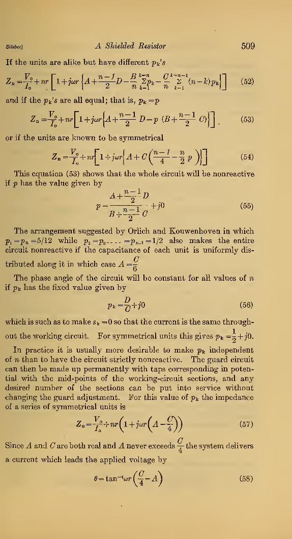
If the units are alike but have different p^'s
V r f r) — 1 Ji k=n rik=n-l ]-\
Zn=4-° + wr 1+jcorU +^Z)-^ Spt-^ 2 {n-DpM (52)-to , L I
^ ^ k=i ^ &=i JJ
and if the 2>k's are all equal; that is, Pk=P
2n=^° +nr[l+jw[^+^Z)-2) (5+^ (7)j] _
or if the units are known to be symmetrical
^" =tI + """[^ + ^"'''{^ + ^(^ " "1 ^ )1] ^^^^
This equation (53) shows that the whole circuit wUl be nonreactive
if p has the value given by
A +'^D2> =—:^—i-+jo (55)
5 +^(7The arrangement suggested by Orlich and Kouwenhoven in which
Pi=Pa=5/12 while Pg =^3 =Pn-i=l/2 also makes the entire
circuit nonreactive if the capacitance of each unit is uniformly dis-
Gtributed along it in which case A =^
The phase angle of the circuit will be constant for all values of nif Pk has the fixed value given by
2>k =§+?0 (56)
which is such as to make Sk =0 so that the current is the same through-
out the working circuit. For symmetrical units this gives p^ =-^ + jO.
In practice it is usually more desirable to make ^^k independent
of n than to have the circuit strictly nonreactive. The guard circuit
can then be made up permanently with taps corresponding in poten-
tial with the mid-points of the working-circuit sections, and anydesired number of the sections can be put into service without
changing the guard adjustment. For this value of pk the impedanceof a series of symmetrical units is
Z, =^+nr(l + jo:r(A-jy^ (57)
CSince A and O are both real and A never exceeds -j- the system delivers
a current which leads the applied voltage by
e^tan-'oirfj-A^ (58)

510 Scientific Papers of the Bureau of Standards [votto
Equation (52) can also be used to estimate the error introduced into
the voltage transformer test by any of the various possible maladjust-
ments which might occm-. Thiis if the impedance R2' (fig- 2) in
the ground side of the guard circuit is in error by a resistance ARand a reactance wAi the various values of ^^k will be changed by anamount
where ?'' = —^ is the resistance per section of the guard circuit, and
the errors thus introduced into the final measurement are
error in ratio factor= — w^—j— (- ——— ) (60)r \3 12n/ '
error in phase angle =
—
— AR( o
~ fo~ ) radians (61)
An error of AR in locating the tap point on a single tmit changes
Pk by
A2)k=^ (62)
and changes the phase angle of the system by
A0= ±e^U- fc
+ ^ radians (63)
For the equipment of the Bureau of Standards using 25 imits, the
error in phase angle would amotmt to 1' at 60 cycles if the ground
side of the guard circuit were out of adjustment by 1,500 ohms or if
the shield of the first imit were connected to a tap 13,000 ohms awayfrom the correct point.
CIf it is assumed that each shield has a capacitance —^ to ground,
Cin addition to the capacitance C=—^ to the working circuit, and
if it is assumed that the potential distribution along the guard wire
is so nearly uniform that the charging current from each shield is
proportional to the nominal potential of that shield above gi'ound,
then it can be deduced that with normal adjustment
^^~2 ^ 12n{2n^ + l-2¥ + 2lc){]c-^ (64)
and insertion of this value in equation (52) leads to
AZn o^^CgCyr^
12n^ (57; 71^ + ) approximate (65)

Silsbce] A Shielded Resistor 511
as the relative error in impedance resulting from the presence of the
capacitance Cg. It will be noted that when expressed in the sameform as equation (34) for the uniformly shielded case, the first
term (which is the only one of importance) becomes identical, thus
confirming the results of the earlier analysis.
From the foregoing equation it is possible to draw some detailed
conclusions on the best way to design resistances of this type. Since
the indeterminate error arising from ground capacitance is in the
main proportional to the product co^Cg Rg C^ Ry, while the powerconsumed by the equipment is
it can be shown that for a given voltage and allowable error the
power is least when Rg=R^ and all things considered this is probably
the best relation for these resistances. It is, of course, also desirable
to minimize both Cg and C^. It can be shown that if a sphere of
diameter di is to be surrounded by a spherical shield of diameter d2
the product of the capacitances between the shield and ground andbetween the shield and its contents is least if d2 = 2di. The actual
resistors to be shielded wiU, of course, not be spherical in form, but
this computation indicates the desirability of a fairly wide clearance
on aU sides between the shield and its contents. The use of oil inside
the tanks as in the present construction increases C^ in direct propor-
tion to the dielectric constant of the oil, but the gain from the in-
creased momentary overload capacity thus obtained probably offsets
this loss.
Roughly one may set the power dissipated
(67)
where w= watts dissipated per unit area of cooling surface at rated
temperature rise and J.w = area exposed to cooling medium. Also to
a very rough approximation
Cg = KAg (68)
where S^=a constant and J.g = area of shield exposed to electrostatic
influence from ground. Combining these equations on the assump-tion that 6w is proportional to Cg, gives for the indeterminate error
^^C^CgR^^K,'''lf/j (69)
This suggests that the errors increase as the fourth power of the
voltage and as the square of the frequency, while they can be reducedby increasing the heat dissipation per tmit area and by increasing the

512 Scientific Papers of the Bureau of Standards ivoi.io
ratio of cooling area to area exposed to ground. This last considera-
tion tends to favor the use of a few units of high resistance since the
inner faces of adjacent cards may contribute cooling surface vsdthout
having much capacitance. On the other hand, the use of large units
tends to increase the magnitude (though probably not the uncer-
tainty) of the correction ur (-j—Ajior the phase angle of the indi-
vidual unit. In the case of the equipment here described the imit of
20,000 ohms was chosen as a moderate extrapolation from the 10,000-
ohm coils for which the residual inductance was accurately known andwith which they could be compared by a simple 2 : 1 ratio. Nowthat the present equipment affords a standard up to 500,000 ohms,the inductance of single units up to this magnitude could be directly
measured.VI. CONCLUSIONS
From the foregoing it may be concluded that a resistance of 500,000
ohms of the subdivided and shielded type here described can be used
on alternating current of commercial frequency up to 30,000 volts
with an accuracy approaching 0.01 per cent or 0.3'.
If the units are constructed symmetrically and if the shields are
maintained at a potential midway between those of the terminals of
the imit, then (a) the current is the same throughout the length of
the working circuit and the constants s-k are all zero; (b) the phase
angle of the circuit is independent of the number of tinits in use.
A single simple measurement of the total capacitance betweenthe resistor and the shield of each unit gives the data needed for
computing the effect on the system of any maladjustment of the
guard circuit.
An additional measurement of the eflFective inductance of the
units is necessary unless the upper limiting value of —j— is found
to be negligible.
The indeterminate error arising from capacitance from shields to
ground is found to increase roughly as the fourth power of the voltage
rating so that the possibility of indefinitely extending the use of re-
sistors of this type to higher voltages does not appear at all promis-
ing, though the present rating of 30 kv can be considerably exceeded
by using larger units, with more effective cooling and with greater
temperature rise.
The writer wishes to acknowledge the valuable assistance con-
tributed by many members of the electrical instrument section of the
Bureau of Standards during the development of this equipment, and
especially to S. Isler, G. T. Morris, J. H. Pirn, and W. W. La Rue,
by whom most of the experimental and constructional work was
done.

siisbeeji A Shielded Resistor 513
VII. NOTATION
A,B, C, Z? = coefficients dependent on the capacitance distribution
in the resistance units.
7lw,^g= areas effective in cooling, and in adding capacitance,
respectively.
a, a' = dimensionless constants which measure the capacitance
effects in uniform resistors (see equations (10) and
(25)).
i = -y/co'C^CgR^Bg
C= capacitance.
Cg = total capacitance between guard circuit and ground.
C^= total capacitance between working circuit and guard
circuit.
0{K) = function giving the distribution of capacitance along a
unit.
D = resistance of dial arm of dc. bridge.
di, dz = diameters of spherical condenser.
E^ = voltage across terminals of kth unit.
7= current.
/k = current entering "live" terminal of kth unit,
/'k = charging current flowing into guard circuit from shield
of kth unit.
JE^= parameter defining the location of an element along the
resistor.
&= integer identifying any section of the resistor.
Z= inductance.
Xw = total inductance of working circuit,
if= mutual inductance.
jTij, ma = roots of equation m* — a^m^ — 6^ = 0.
iV=true ratio of voltage transformer.
71 .=total number of units in resistor.
2?k=relative potential of shield lpk=y—^^— j.
Q =resistance standard in dc. bridge.
B =resistance.
R^, Rg =total resistances of working circuit and guard circuit,
respectively.
R2 =resistance opposing the secondary voltage of the trans-
former.
rk =resistance of a single section of working circuit = "^
r' =resistance of a single section of guard circuit =
nRo

514 Scientific Papers of the Bureau of Standards [voi.to
Sk =shunting coefficient of a unit Sk= j^
'
F=potential.
l^wj Vg =potential of any point on working circuit or guard cir-
cuit, respectively.
Vn = potential of ungrounded terminal of complete resistor,
Fk =potential of "live" terminal of kth unit.
Tf= total power dissipated.
w =power dissipated per unit area of cooling surface.
Z =impedance.
Zo =impedance of a circuit defined by current delivered at
Z=0.Zow =impedance of working circuit defined by current de-
livered at ^"=0.
Zn =impedance of circuit of n units in series.
2k =impedance of individual unit.
d =phase angle of impedance or of transformer.
"^-^V4J2
1 ^
—
Ti See equation (28)
.
p = 1 + P^ + Tf^ p • See equation (32)
.
CO =27r X frequency.
Washington, June 16, 1925.
^


![Thermal expansion of copper and some of its important ...nvlpubs.nist.gov/nistpubs/ScientificPapers/nbsscientificpaper410... · Hidnert] ThermalExpansionofCopperAlloys 93 themicrographsandthepreparationofthesamples,givenby](https://static.fdocuments.net/doc/165x107/5a9e2d007f8b9a0d7f8b483e/thermal-expansion-of-copper-and-some-of-its-important-thermalexpansionofcopperalloys.jpg)


![NONFLAMMABLE LIQUIDS FORCRYOSTATS - NIST Pagenvlpubs.nist.gov/nistpubs/ScientificPapers/nbsscientificpaper520... · Kanolt] NonflammableLiquidsforCryostats The ofthe Theof istheof](https://static.fdocuments.net/doc/165x107/5aba2d137f8b9a297f8b5f74/nonflammable-liquids-forcryostats-nist-nonflammableliquidsforcryostats-the-ofthe.jpg)

![Specific heat of superheated ammonia vapor - NIST Pagenvlpubs.nist.gov/nistpubs/ScientificPapers/nbsscientificpaper501... · ®igh n%Sii c?aw] SpecificHeatofSuperheatedAmmoniaVapor](https://static.fdocuments.net/doc/165x107/5a9e31327f8b9a0d7f8b79d6/specific-heat-of-superheated-ammonia-vapor-nist-nsii-caw-specificheatofsuperheatedammoniavapor.jpg)