A Service Publication of Lockheed Aeronautical Systems …...A SERVICE PUBLICATION OF LOCKHEED...
16
A Serv ic e Pub li cat ion of L oc k heed Aero n au ti ca l Sys t ems Com pany
Transcript of A Service Publication of Lockheed Aeronautical Systems …...A SERVICE PUBLICATION OF LOCKHEED...

A Service Pub lication of Lockheed Aeronau ti cal Sys tems Company

A SERVICE PUBLICATION OFLOCKHEED AERONAUTICALSYSTEMS COMPANY
EditorCharles I. Gale
Art DirectorAnne G. Anderson
Vol. 19, No. 1, January-March 1992
CONTENTS
2
3
10
14
Focal PointS. S. Clark, ManagerCustomer Training Systems Dept.
Checking T56 Engine PerformancePerformance checks can identifypotential engine problems and cutcosts. An updated performancecalculation method yields fester,more accurate results.
Cargo Ramp SavvyNo pert of the Hercules worksharder then the cargo ramp. Thesetroubleshooting hints can helpkeep the ramp on the job.
Mixing MLG Shock StrutsDo “hard” and “soft” struts mix?Only in very special circumstances.Here are some guidelines.
Photographic Support: John Rossino
Covers: This KC-130T-30 is one of twonew “stretched” Hercules tankers deliveredto the U.S. Marine Corps late last year.Barrel plugs forward end aft of the wingextend the fuselage 180 inches, providing a30% increase in volume ever the standardconfiguration. The back cover shows thel00-inch forward plug during assembly. Thetwo Marine tankers are the first stretchedC-l 30s to enter the U.S. military inventory.
Syd Clark
Maintaining the Quality Advantage
B efore a new Hercules aircraft leaves the LASCproduction facility in Marietta, Georgia. we make
certain it has been built to the very highest qualitystandards modern technology can offer. All of ourefforts are directed toward a single goal: ensuring thatevery customer’s expectations about his Lockheedairlifter will be met, and even exceeded.
It is an approach that makes a difference you canmeasure. The first production C-l 30 is still on the job,38 years after it was produced. During the interveningyears, many other kinds of aircraft have been de-signed, built, and put info service. More than a fewhave already vanished from the scene, little more thanfootnotes to aviation history. The difference? It’ssimply a matter of quality. Quality that is designed-in
and then built-in not only gives en airplane the ability to do its job today, but thepotential for continuing to do it tomorrow.
A good beginning is therefore only part of the story; the rest has to do withexploiting the potential. How much of en aircraft’s possible service life will berealized is largely a question of the care and maintenance it receives after delivery.This is where we can help. Supplying answers to the hows and whys of aircraftmaintenance is what the Customer Training Systems Department is all about.
We have a proud record of performance in this arena. In some 40 years ofoffering customer training services, we have taught aircraft maintenance to over10,000 technical and managerial personnel, and produced more than 400 items ofmaintenance training equipment. The fact that cur training facility is an integral partof a major aircraft manufacturing center offers special advantages for cur students.It helps ensure that the course content we include is fully in step with all of thenewest developments in aircraft products end procedures.
We provide expert training in all of the major aircraft maintenance fields, andin a wide variety of specialty areas es well. To give just one example, with nearly70 countries now flying the Hercules, maintenance training has taken on a distinctlyinternational flavor. Customer Training Systems has responded to this globalenvironment by offering comprehensive English language and basic technical skillsprograms tailored to satisfy the demands of the customers who need them.
Whether the requirement is for language skills, en aircraft structures update, orin-depth instruction on en advanced inertial guidance system, the Customer TrainingSystems Department stands ready to provide Lockheed customers with the verylatest and very best in aircraft maintenance training. It’s a great way to maintain thequality advantage!
Sincerely.
‘Manager,Customer Training Systems Department
H. L. BURNETTE DIRECTOR
FIELD SUPPLYSUPPORT SUPPORT
J. D. Adams J. L. Bailey
TECHNICALPUBLICATIONS
A. G. Hunt
RM&SDESIGN
H. D. Hall
CUSTOMERTRAINING
S. S. Clark

by Roy H. Webber, Staff EngineerSupport Equipment/Automatic Test Systems Department
Periodic evaluation of T56 engine operation by the use of perfor-mance checks can be highly beneficial to the Hercules operator.
All gas turbine engines gradually loseefficiency over time. Compressorserode, seals wear, and turbines deterio-rate because of the effects of heat andsulfidation. The engine performancecheck provides a systematic way ofmonitoring the operating efficiency of anengine as the service hours accumulate.
Regular checks of engine perform-ance help reduce costs by identifying theless efficient, low-performance enginesthat are wasting precious fuel. Thechecks can also detect potential troubledeveloping in an engine before it showsup in the form of an obvious malfunc-tion. This can prevent small, inexpensiveproblems from turning into big, costlyones. Periodic checks can also help avoidenroute breakdowns which could delaycargo and strand a crew at a remoteairport while engine repairs are beingcarried out.
Performance Check Intervals
Neither Lockheed nor Allison GasTurbine Division, the manufacturer ofthe 501/T56 engines used on all Herculesaircraft, recommend a specific intervalfor making engine performance checks.However, the test should always be un-dertaken if the engine instruments appearto be indicating abnormal values whenthe takeoff power check is performed, orthere is reason to believe that an engineis not able to produce takeoff power.
Otherwise, it is up to the individualoperator to use his own judgment regard-ing when these tests should be undertak-en. This allows each Hercules operatorto tailor the engine performance check-ing cycle to best fit the requirements ofhis particular operation.
Even though Allison and Lockheeddo not specify any particular period, both
Lockheed SERVICE NEWS V19Nl 3
recommend, as a minimum, that a performance check beaccomplished and recorded after installation of a new ornewly overhauled engine. This establishes a set ofbaseline values to which subsequent performance runscan be compared.
Some operators who have particularly strong main-tenance programs routinely carry out performancechecks on each new engine they receive, including thoseacquired during the delivery of a new airplane. Thisensures that complete historical data will be available onevery power plant in their inventories.
achieve scores that are quite so high, but they still exceedthe basic requirements. Most newly rebuilt T56 enginesare able reach about 102% efficiency Engine perfor-mance will gradually fall off after installation and use,but in most cases engines may be continued in serviceuntil their performance efficiency level has droppedbelow 95 % .
A Question of Method
Understanding Performance Checks
The Allison performance efficiency rating for a newengine is based upon test cell data. In order to obtaincomparable values for an installed engine, appropriatedata are collected from the engine being tested and thenadjusted mathematically.
The engine performance check measures engineoperation in terms ofpercent efficiency. This should notbe confused with the theoretical concepts of thermalefficiency as used in engineering and thermodynamics.As applied here, percent efficiency is a measure of thepower output of the engine under test when compared tothat of a new engine. An engine whose efficiency ratingis 100% is one that is capable of fully meeting Allison’sspecification for the performance of a new engine underthe same physical conditions.
Over the years, four different methods of making theengine performance check have evolved. Each may beregarded as representing an improvement over themethod immediately preceding it, but all remain autho-rized procedures. They all require that the same data betaken; the differences lie mainly in the equipment usedand the amount of automation employed in convertingthe data to a performance figure. Done properly, all willgive similar results with only minor variations.
In practice, most brand-new engines are able to The first three methods are covered in the engineexceed this specification. It is not uncommon for new maintenance manuals, but the fourth and latest methodengines to yield results of 106% or 107% efficiency was developed only recently. It will be included in fu-duringaperformancecheck. Overhauled engines seldom ture updates of the technical handbooks. In addressing
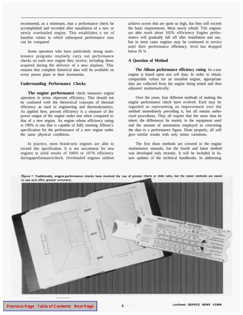
7. Traditionallv. engine performance checks have involved the use of printed charts or slide rules, but the newer methods are easier
Lockheed SERVICE NEWS V19Nl

the particular capabilities of the most recent approach, itwill be helpful to first review the strategies used by theearlier methods.
Method 1: the Charts
This method involves the use of printed charts, ornomographs, included in the technical manuals, toconvert the measured data into a performance figure.Although somewhat tedious, many operators have grownaccustomed to using this method and still prefer it.
The main disadvantage to using this approach is thatit requires the user to enter a variety of data onto charts,interpret the results, and then manually carry out a seriesof calculations to arrive at a figure for the performanceefficiency of the engine being tested. Each of the manysteps involved offers opportunities for making errorswhich could nullify the value of the results.
Method 2: the Slide Rule
This method, which was introduced in the 197Os,uses the Allison PN 6799970 slide-rule calculator toconvert the measured data to a performance figure. Themathematical equations, or algorithms, built into theslide-rule calculator are exactly the same as those thatare used to make up the charts of method 1. The result-ing calculations should, and do, yield the same results asif the charts had been used. The slide-rule calculator
simplifies the process and makes the procedure some-what more convenient to use. The main disadvantage isonce again the problem of accuracy. The slide rule mustbe used properly and the various data points interpolatedcorrectly if valid results are to be obtained.
Method 3: an Electronic Breakthrough
This method was introduced in the early 1980s.After the engine data are collected, a Hewlett-PackardHP-41CV hand-held programmable calculator is used tomake the conversion from raw data to an engine perfor-mance figure. The necessary algorithms are contained onmagnetic cards which are pre-programmed by Allison.The cards are read into the calculator with a magneticcard reader that attaches to the calculator.
The algorithms built into the magnetic cards remainthe same as those used for the first two methods, but theuse of the programmable calculator in this method helpseliminate the human lapses which can degrade theaccuracy of the results when the first two methods areused. Another improvement introduced with this methodis the use of a digital electronic thermometer. Thisdevice is provided with the hardware kit to make moreaccurate temperature measurements possible.
The principal drawback to the method employing theHP-41CV calculator is that the procedure for enteringdata and using the calculator is not particularly user-
figure 2. The PN 3403218-l Engine Performance Calculator Kit contains an HP-48SX calculator, Allison PN 32051184 PROM module,accessories, and full instructions.
Lockheed SERVlCE NEWS V19Nl

Figure 3. The ambient air temperature must be measured as accurately as possible for valid engine performance results. Be sure to taketemperature readings in a shaded area.
friendly. Special care and concentration are needed untilthe operator has performed the procedure often enoughto become familiar with the various keystrokes required.
Method 4: an Electronic Upgrade
A new and enhanced method for making engineperformance calculations has been developed during thepast year. This engine performance calculation methodoffers some significant improvements over the previousapproaches.
The main impetus for the development of the newmethod is the fact that the HP-41CV is no longer avail-able from Hewlett-Packard. It was necessary to adapt theengine performance program to Hewlett-Packard’snewest scientific calculator, the HP-48SX. A number ofother improvements were also made in the process.
Developing the New Method
The improved method was developed as a jointAllison-Lockheed project. Taking advantage of theenhanced capabilities of the HP-48SX, the program nowuses on-screen prompts to define the user inputs to thecalculator. The new method is thus much more user-friendly, since the technician no longer needs to read the
keystrokeentry requirements from separate instructions,as is the case in method 3. The new program also fea-tures a significant reduction in the number of keystrokesrequired.
Somechanges were made in the program algorithmsas well; this results in greater accuracy at temperaturesbelow 0°F. The new algorithms were developed afteryears of experience in computerized testing of engineperformance at the Allison factory. These same tests,incidently, also confirmed the validity of the olderalgorithms for the more moderate temperature ranges.
Another improvement was to incorporate the instal-lation effect (always 100% in the case of the Herculesaircraft) into the algorithms, eliminating a step in thedata entry sequence. Also, if the operator desires tomeasure performance for more than one engine, a simplekeystroke, prompted by the display, allows this to bedone without having to re-enter pressure altitude andoutside air temperature.
The new calculator, together with appropriatesoftware, and instructions, is contained in the PN3403218-l Engine Performance Calculator Kit, which isavailable from Lockheed. Further details and orderinginformation will be found at the end of this article.
6 Lockheed SERVICE NEWS V19Nl

Figure 4. Pressure altitude is also a critical parameter. Averaging the readings obtained from two flight station altimeters reduces thechances of error.
Operators currently using the older method designedaround the HP-41CV should feel comfortable aboutcontinuing to employ it. The new system is easier to use,but the only significant difference between the oldermethod and the new one from the standpoint of accuracyis the greater precision at low temperatures.
2.
3.
Performance Checks-General Requirements
Skill, care, and accuracy are the keys to successfulengine performance testing regardless of which methodis used, and it is helpful to review the basic generalprinciples that apply. Note that the values given in thediscussion below are applicable only for a T56-A-15engine being tested with new PN 3403218-l kit. Differ-ent numbers may apply when other members of the501/T56 engine family are under test, or if one of theolder performance calculation methods is employed.
4.
1. The Hercules is a powerful airplane. When testingengines, always operate two symmetrical engines(and only two) at the required power level at the 5.same time-for example, No. 1 and No. 4. Observeall engine run safety requirements described in theauthorized technical manuals and your organiza-tion’s regulations. See also the article “Engine RunSafety” in Vol. 18, No. 2 of Service News magazine.
Be sure to calibrate the tachometer, torquemeter,and turbine inlet temperature indicator of the affect-ed engine before doing a performance check.
The ambient temperature should be measured asaccurately as possible, in a shaded area under thewing. A precision mercury thermometer, or a digitalelectronic thermometer, are the instruments ofchoice. Let the thermometer stabilize fully beforeuse. A2.8'C error (5'F)results in a 2% error in theengine performance calculation.
Obtain and record the pressure altitude. This shouldbe the aircraft altimeter reading when 29.92 inchesof mercury is set in the “Kollsman window” of thealtimeter. Average the readings of two altimeters onthe flight deck. A 300-foot error in the altitudereading will result in a 1% error in calculatedperformance.
Start the APU, position the brake select switch toEMERGENCY, ensure that the auxiliary hydraulicpump is turned on, and set the parking brake. Do notdepend on chocks to hold the aircraft. Only thebrakes can hold the airplane once engine power isapplied.
Lockheed SERVICE NEWS V19Nl 7
6. Start and warm up the engine to be checked and thesymmetrically opposite engine. Leave the APUrunning and the APU generator on line. EngineRPM should be adjusted as close as possible to100% (13,820 RPM). A 1% variance in RPM canaffect performance calculations by up to 0.9%.
7. Set the engine bleed air switch to the CLOSE/OFFposition. Turn off the engine-driven hydraulic pumpon the engine being tested.
8. To make the performance check, advance the powerlever toward TAKEOFF until 1050°C TIT or19,600 inch-pounds of torque (4289 hp) is reached,whichever occurs first. Read and record the indicat-ed torque and TIT. Remember that application ofpower beyond authorized limits can damage theaircraft or wing structure.
9. Read the torquemeter as accurately as possible. A200 inch-pound error will result in a 1% error incalculated performance.
10. Accuracy in TIT readings is just as important. A5°C mistake in reading the TIT indicator will resultin a 1% performance calculation error.
Calculation and Interpretation
Using your authorized technical manual and one ofthe methods outlined above, take the required data anddetermine engine performance in accordance with theinstructions for the method used. Be sure to recheck allcalculations for accuracy.
If the performance calculation indicates that engineperformance efficiency is less than 95 %, one or more ofthe maintenance actions shown above may restoreperformance to within limits. If these maintenanceefforts cannot restore performance, the engine should beremoved for overhaul.
Easier, More Accurate Checks
Engine performance checks should be an integralpart of Hercules fleet maintenance. It is well worthwhilefor every operator to see to it that an approved techniquefor carrying out these checks has been mastered, and thatthe checks are being performed on a regular basis. Thepayoff will be safer, more reliable flight operations, andan extension of service life between engine overhauls.
The recently developed engine performance check-ing method featuring the HP-48SX electronic calculatormakes performance checking easier and more accuratethan ever before. Operators interested in using the newmethod should obtain the complete PN 3403218-lEngine Performance Calculator Kit, which may beordered from Lockheed. The kit includes an HP-48SX
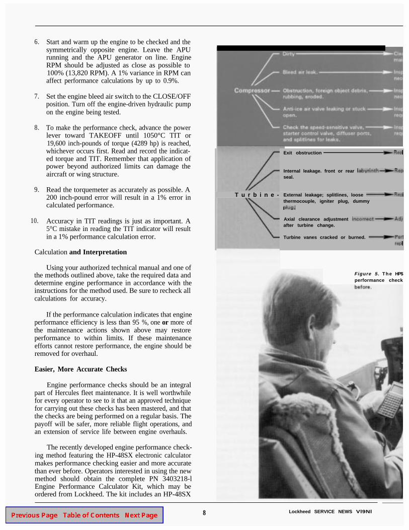
T u r b i n e -
Exit obstruction
Internal leakage. front or rear seal.
External leakage; splitlines, loose thermocouple, igniter plug, dummy
Axial clearance adjustment after turbine change.
Turbine vanes cracked or burned.
Figure 5. T h e HP$performance check
8 Lockheed SERVICE NEWS Vl9Nl

LOW ENGINE PERFORMANCE CHECKLIST
required.
rewired
required.
clearance.
borescope inspection. Repair or necessary.
electronic calculator makes engineeasier and more accurate than ever
Lockheed SERVICE NEWS V19Nl
calculator, an Allison PN 32051184 PROM Module, adigital thermometer, and instructions. All the kit mateti-als are packaged in a handy briefcase-type container.
The HP-48SX electronic calculator is programmedfor carrying out the engine performance check by usingthe PROM module included with the kit. The AllisonPROM Module is designed for checking engine perfor-mance on military and commercial C-130/Ll00aircraft,and also on P-3, CP-140, Convair 580, E2, and C2aircraft. It will check T56 engines of the following dashnumbers: A-l, A-14, A-14LFE, A-15, A-l5LFE, A-16,A423, A425, A426, A427, and 501D-22 and 22A.
Also included in the Allison PROM module are thealgorithms for doing a check called minimum power,which is used to calibrate the engine torquemeters.Further data about the operation of this kit and orderinginformation are available from: Customer Supply Busi-ness Management, Dept. 65-l 1, Zone 0577, Lockheed-LASC, Marietta, GA 30063; Telephone 404-494-4214;Fax 404-494-7657; Telex 804263 LOC CUST SUPPL.
The author and the Service News staff wish to thankTom Allen, Bob Mangham (page 6), John Leckie (pages8-9), and photographer Lamar Hawkins for their valuedassistance in the preparation of this article.
9

by R. S. (Biff) Barger, Field Supporr Representative, SeniorAirlift Field Service Department
The cargo ramp of the Hercules airlifter is anexceptionally versatile part of a remarkably versatile
aircraft. Its unique design allows cargo loading fromtruck-bed height, and it can be lowered to the ground toallow easy access for roll-on equipment. When closedand locked, the ramp becomes part of the aircraftstructure and seals for pressurization. Cargo can also becarried on the ramp, in effect increasing the capacity ofthe cargo compartment.
This ten-foot square platform is a real workhorse,and relatively little attention is required to keep it on thejob. No mechanical system can endure forever withoutan occasional repair, but most ramp problems arereasonably straightforward even when they do occur.Usually there is obvious physical damage or clearlymalfunctioning components, and this simplifies themaintenance effort. Occasionally, however, a rampproblem turns up that proves a bit more challenging.Here are three problems involving the ramp that fall intothat category. They can test the skills of even the mostpracticed troubleshooter:
l Excessive side-to-side movement of the ramp.
l An open ramp with hooks extended.
l A hook at ramp station 10 not engaging its hookretainer.
The first complication that arises when one of theseproblems is encountered is that the usual technicalreference sources may fail to offer much assistance.There is a reason for this. As good as they are at provid-ing mechanical details and troubleshooting techniques,the maintenance manuals do not attempt to offer muchinsight into the complexities of the man-machine inter-face. And the human factors are often very muchinvolved in ramp maintenance questions.
None of these are mechanical problems inherent inthe ramp itself. Rather, they have to do with the way theequipment is operated and the special requirements of itsdesign. A close look at each of these situations will helpexplain why these problems occur, and how best tocorrect them.
Excessive Side-to Side-Movement
The next time you see the ramp open and the aerialdelivery system (ADS) support arms disconnected, graban actuator rod and rock the ramp sideways. You will beamazed by the amount of movement present. It’s enoughto make you think the ramp bushings are worn or evenmissing. Note that this apparent excessive movementoccurs only when the ADS arms are disconnected, orwhen the ramp is in a position other than horizontal.When connected and fully extended, the arms act assway braces which restrict such movement.
10 Lockheed SERVICE NEWS V19Nl
In fact, the ramp hinge was designed to be a non-rigid installation to ensure that no binding or unduestress would be present when the ramp is closed andlocked. There must be a certain amount of play toensure proper opening and closing. Also, uneven loadson the ramp could cause problems if brought to bear ona “hard point” ramp hinge configuration. For thesereasons, the bushings are installed in a slotted configura-tion that will allow the necessary play.
The maintenance manuals do not provide instruc-tions for checking the ramp play while the ramp isinstalled on the aircraft. No guidelines have beenpublished setting allowable limits on the amount of playattributable to bushing wear because experience hasshown that the ramp attach bushings are not oftensubject to serious wear. Data pertaining to permissiblewear of the bushings themselves are found in the appli-cable structural repair manuals such as SMP 583 orT.O. lC-130A-3. Unfortunately, the procedures de-scribed for determining the wear require that the rampbe removed from the aircraft to perform an inspection.
Several Hercules operators have inquired if it wouldbe possible to devise a method of checking the conditionof the slotted bushings without removing the ramp. This
question was put to Lockheed engineering for consider-ation, and a study was undertaken.
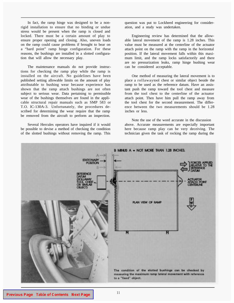
Engineering review has determined that the allow-able lateral movement of the ramp is 1.28 inches. Thisvalue must be measured at the centerline of the actuatorattach point on the ramp with the ramp in the horizontalposition. If the lateral movement falls within this maxi-mum limit, and the ramp locks satisfactorily and thereare no pressurization leaks, ramp hinge bushing wearcan be considered acceptable.
One method of measuring the lateral movement is toplace a rol lawaytool chest or similar object beside theramp to be used as the reference datum. Have an assis-tant push the ramp toward the tool chest and measurefrom the tool chest to the centerline of the actuatorattach point. Then have him pull the ramp away fromthe tool chest for the second measurement. The differ-ence between the two measurements should be 1.28inches or less.
Note the use of the word accurate in the discussionabove. Accurate measurements are especially importanthere because ramp play can be very deceiving. Thetechnician given the task of rocking the ramp during the
Lockheed SERVICE NEWS V19Nl 11

wear check will nearly always declare that the move-ment feels much greater than 1.28 inches; four or fiveinches is sometimes the estimate. Don’t rely on guess-work; measure it to be sure.
Ramp Open With Hooks Extended
This condition may suddenly appear, as if fromnowhere, during manual operation of the ramp. It isusually caused by rotating the ramp control knob in thewrong direction or selecting position number 5 with theramp open and then operating the hand pump.
Here is a good rule to follow whenever you operatethe ramp manually:
When using the manual ramp control, be sureto rotate the knob only in a clockwise direction.This will ensure that the indicated position willremain in sequencewith the internal valves.
The ramp control knob should only be rotated in a clockwise The manual ramp control panel and the hand pump are locateddirection to maintain proper valve sequencing. just aft of the left paratroop door.
Failure to follow this sound advice could cause thehooks to extend with the ramp open. This is a situationwhich can have serious consequences if not handledproperly. If the ramp is closed with the hooks extended,the sloping longerons will be damaged.
Do not use the auxiliary hydraulic pump and electri-cal control switches when attempting to correct thiscondition. Things tend to happen too fast when you usethe auxiliary hydraulic pump. Stay with the manualcontrol valve instead.
This list makes the appropriate corrective actionappear obvious: simply select position number 1 andoperate the hand pump until the hooks retract. Unfortu-nately, this usually doesn’t work. What normally doesoccur, much to the surprise of the operator, is that theramp starts rising and the hooks remain extended. If thisoperation is not terminated, the ramp will continue tomove toward closed until the hooks strike the slopinglongerons.
The ramp manual control is a round knob whichmay be placed in six positions. These are:
1. Unlock the ramp2. Lower the ramp3N. Neutral
4. Raise the ramp5. Lock the ramp6N. Neutral
What is the cause of this strange behavior? Theanswer is really quite simple. The design of the hooksand hook retainers requires that the ramp be raised asmall amount to initiate unlocking. This lifts the weightof the ramp off the hooks. When position number 1 isselected, fluid is ported to the “close” side of the rampactuators and to the “unlock” side of the lock actuator.The two ramp actuators have large-diameter pistons toenable them to lift the weight of the ramp. In compari-
12 Lockheed SERVICE NEWS V19Nl

son, the lock actuator is quite small. It must movecontrol rods, connecting rods, hook push rods, andbellcranks to extend and retract the hooks. This is a bigundertaking for such a small actuator. The result is thatin most situations, raising the ramp turns out to be thepath of least resistance.
The ramp therefore moves upward, and will contin-ue to do so until it contacts the fuselage and can travelno further. The path of least resistance is now trans-ferred to the lock actuator and the hooks begin to move.This is fine as long the hooks start from the retractedposition. But if they are already extended, the aircraftstructure will be damaged when the hooks contact it.
To retract the hooks with the ramp open, the path ofleast resistance must be shifted to the lock actuator. Thebest way to accomplish this is to add weight to the ramp.Adding the required amount of weight is easy. Havefour people (the bigger the better) stand on the aft edgeof the ramp while you select position number 1 andoperate the hand pump. The heavily loaded ramp willresist movement, and the hooks will retract instead. Theramp can then be closed in the normal manner.
Hook at RS 10 Not Engaging Retainer
The failure of a hook at ramp station 10 to engageits hook retainer is a problem which shows up mostfrequently when the ramp is loaded with cargo and theaircraft is parked after completing a turn.
The hook at ramp station 10 may fail to engage if the ramp isheavily loaded and the aircraft is parked in a turn.
Moving the aircraft in a straight line for two revolutions of themain tires may permit all hooks to engage properly.
When the Hercules aircraft is towed-or taxied in aturn, the main landing gear tires are deflected laterally.Before stopping the aircraft, it is always best to proceedforward in a straight path for several more feet to avoidleaving the tires deflected and under stress while theaircraft is parked.
It’s important to remember that lateral deflectioncan affect more than just the tires; it can also produce adeformation of the fuselage. If the aircraft does notproceed in a straight path far enough before beingparked, a slight twist will remain. This makes it difficultfor a heavily loaded ramp to align properly and engageboth ramp station 10 hook retainers.
Before you get the tool box and start making adjust-ments when this happens, get out the tow bar andreposition the aircraft. Moving the aircraft in a straightpath for about two revolutions of the main tires shouldbe more than enough to take out the twist. Then tryclosing the ramp again. If it still will not lock properly,it’s time to make those adjustments.
Lockheed SERVICE NEWS V19N1 13

14
by Tom Zembik, Service AnalystAirlift Field Service Department
Herculesoperators often ask about possible restric-tions or other problems that could be involved in
using hard and soft MLG struts on the same Herculesaircraft. The question arises because although currentproduction Hercules are normally equipped with softstruts, hard struts are still in widespread use. In fact,several operators have a mix of aircraft, some equippedwith hard struts and others with soft. In such cases,varying quantities of both types will ordinarily be repre-sented in the operator’s spares inventory. If one kindruns short, it may appear convenient to release anaircraft for flight even though it is not equipped withstruts that are all of the same type.
Lockheed engineering cautions that such mixing ofstrut types is not advisable. It should only be done incase of an emergency situation, and then only for a one-time flight. If conditions seem to warrant mixing the twotypes of struts, the soft strut (450 psi) should be placedin the aft position, and the hard strut (215 psi) in theforward position and serviced to 285 psi. The sink rateduring landing should also be monitored carefully; in nocase should it exceed 300 feet per minute.
Hard vs. Soft
The pressure values given above may seem puzzlingto the non-specialist because the soft strut is seen torequire higher inflation pressures than the hard one. Byway of clarification, it should be recalled that “soft” or“hard” in the case of Hercules MLG strut types refers tothe strut’s performance as a shock absorber rather thanto its inflation pressure.
Viewed in this light, the soft strut is appropriatelynamed. Despite its higher inflation pressure, the greaterair volume and other design characteristics of the softstrut ensure that it transmits significantly less stress tothe airframe during landings and taxi operations thandoes the hard strut. Although the two types have some-what different operating characteristics, hard struts arenearly identical in design and appearance to soft struts,and one type may be converted to the other with rela-tively minor modifications. “Understanding Struts,” anarticle published in Service News, Vol. 13, No.2 (April-June 1986) provides a detailed look at the subject ofhard and soft struts.
Lockheed SERVICE NEWS V19N1

If you are unsure whether your Hercules has hardstruts or soft struts, there are several ways to find out.One way is to examine the data plate on the strut to seethe part number or servicing pressure. This informationcan then be compared with information in the appropri-ate illustrated parts breakdown or maintenance manualto provide an answer. Unfortunately, you cannot dependon the color of the data plate itself as a designation forhard or soft struts. All struts manufactured in the lastdecade or so, hard or soft, have data plates that are redin color.
Checking the Numbers
The following table may be of some help. It con-tains a list of C-130 MLG part numbers and indicateswhich of the strut assemblies are hard struts and whichare soft.
II Basic PN Dash Number Soft/Hard 11
695001 (none)
695001 -6
695001 -9
370438 -1
370438 -5
hard
hard
hard
hard
hard
370438 -7
370438 -13
hard
hardI
II 370438 I -21 I soft II
388058 -1 hard
388058 -7 hard
388058 -9 soft
388058 -19 soft
3316498 -1 soft
3316498 -7 hard
Lockheed SERVICE NEWS V19N3 15
Another way to distinguish hard struts from softstruts is to manufacture a piece of wire approximatelyseven inches long with a small hook at one end. Jack theaircraft and deflate the strut to be checked, following allprocedures and safety precautions described in theauthorized aircraft maintenance manual. Now removethe servicing valve from the top of the strut and insertthe wire hook into the opening far enough to hook thebottom of the standpipe. Mark the wire at the valve bossand take a measurement. If the measurement is 5.79inches, you have a soft strut. If the value is 3.06 inches,y o u are dealing with a hard strut.
Update on the New Lockheed -
Outflow and Safety ValveTester
The Outflow and Safety Valves Test Setdescribed in Service News, Vol. 18, No. 1(January-March 1991), was originallylisted only under its Lockheed part num-ber, 3403248-I.
The unit has now received a NationalStock Number (NSN) as well. It is NSN4920-01-354-l 265. This should simplifythe ordering process for many C-130maintenance organizations.