A Semantic-Driven Framework for Facilitating Reusability ...€¦ · modeling of construction...
225
University of Alberta A Semantic-Driven Framework for Facilitating Reusability and Interoperability of Construction Simulation Modeling By Farzaneh Saba A thesis submitted to the Faculty of Graduate Studies and Research in partial fulfillment of the requirements for the degree of Doctor of Philosophy in Construction Engineering and Management Department of Civil and Environmental Engineering ©Farzaneh Saba Fall 2012 Edmonton, Alberta Permission is hereby granted to the University of Alberta Libraries to reproduce single copies of this thesis and to lend or sell such copies for private, scholarly or scientific research purposes only. Where the thesis is converted to, or otherwise made available in digital form, the University of Alberta will advise potential users of the thesis of these terms. The author reserves all other publication and other rights in association with the copyright in the thesis and, except as herein before provided, neither the thesis nor any substantial portion thereof may be printed or otherwise reproduced in any material form whatsoever without the author's prior written permission.
Transcript of A Semantic-Driven Framework for Facilitating Reusability ...€¦ · modeling of construction...

University of Alberta
A Semantic-Driven Framework for Facilitating Reusability and Interoperability of Construction Simulation Modeling
By
Farzaneh Saba
A thesis submitted to the Faculty of Graduate Studies and Research in partial fulfillment of the requirements for the degree of
Doctor of Philosophy in
Construction Engineering and Management
Department of Civil and Environmental Engineering
©Farzaneh Saba Fall 2012
Edmonton, Alberta
Permission is hereby granted to the University of Alberta Libraries to reproduce single copies of this thesis and to lend or sell such copies for private, scholarly or scientific research purposes only. Where the thesis is
converted to, or otherwise made available in digital form, the University of Alberta will advise potential users of the thesis of these terms.
The author reserves all other publication and other rights in association with the copyright in the thesis and,
except as herein before provided, neither the thesis nor any substantial portion thereof may be printed or otherwise reproduced in any material form whatsoever without the author's prior written permission.

Dedicated to my beloved parents
Hamidreza and Azar
And
to my lovely siblings
Kazem and Naghmeh

Abstract
This research describes a semantic-driven framework to facilitate reusability and
interoperability of simulation and modeling of construction processes. An immense
amount of knowledge of construction processes and simulation modeling is needed to
develop construction simulation models. Knowledge intensity of construction simulation
models makes the development process an effort and time consuming process. The
research described in the thesis is motivated by the need to effectively reuse the captured
and represented knowledge throughout the life cycle of simulation models. Our approach
addresses these challenges through ontological modeling and linking construction
simulation modeling concepts composed of (i) ontology of the construction process, (ii)
ontology of simulation modeling constructs and elements and (iii) ontological
representation of simulation models. In this research, semantic web approaches and
techniques have been utilized in different aspects: structured documentation and
modeling of construction processes through hierarchical concepts and relationships
between them using semantic web languages such as XML, RDF, and OWL; mapping
techniques for linking and knowledge extraction between modeling ontologies; and
reasoning and inference for knowledge discovery. Stand-alone construction simulation

models and a large-scale HLA-based distributed simulation model of industrial
construction processes have been outlined in order to illustrate the approach.

Acknowledgements
First and foremost, I would like to thank my Ph.D. supervisor, Dr. Yasser Mohamed, for his strong support and encouragement during the course of my research. I am also deeply indebted to Dr. Simaan Abourizk for his critical insight throughout the entire research process and also serving as my candidacy and doctoral committee chair.
I would like to acknowledge Dr. Jeffrey Rankin for serving as my external examiner and providing invaluable suggestions. I am also grateful to my other doctoral committee members, Dr. Roger Cheng and Dr. Michael Lipsett for their thoughtful review and supportive advice.
I would like to take this opportunity to thank Brenda Penner, Stephen Hauge, Hosein Taghados and other faculty members and staff and colleagues in construction engineering and management group who assisted me during this work.
During my work at University of Alberta I was fortunate to make lifelong friendships with many great people. Being away from family, they were the support throughout all the ups and downs of my graduate student life, especially Ali Gorji, Katayoon Navabi, Atoosa Zahabi and Mohsen Danaie, who the last has become a very special person in my life.
Last but not least, my heartfelt appreciations go to my family for their unconditional love, care and support throughout all the stages of my studies. This thesis is dedicated to them.

Table of Contents
Chapter 1: Simulation modeling of construction processes ................................................................. 1 1-1 Introduction ................................................................................................................................. 1 1-2 Simulation Modelling Processes ................................................................................................... 2 1-3 Reuse in Simulation and Modeling ............................................................................................... 4 1-4 Research Motivation .................................................................................................................... 6 1-5 Thesis Objectives and Anticipated Contributions .......................................................................... 7 1-6 Research Methodology................................................................................................................. 7 1-7 Thesis Organization ..................................................................................................................... 8 1-8 References ................................................................................................................................... 9 Chapter 2: Industrial Construction Domain and Related Models ..................................................... 12 2-1 Introduction ............................................................................................................................... 12 2-2 Industrial Construction ............................................................................................................... 13
2-2.1 Construction phase ............................................................................................................. 15 2-2.2 Industrial Construction: fabrication, assembly, and site installation ..................................... 16
2-3 Modeling Industrial Construction Processes ............................................................................... 20 2-4 Distributed Large-scale Industrial Construction Modeling .......................................................... 22 2-4.1 HLA based large-scale industrial construction modeling ......................................................... 22
2-4.2 Industrial construction simulation background .................................................................... 23 2-4.3 Industrial construction federation........................................................................................ 25 2-4.4 Federation object model of the industrial construction federation ........................................ 25 2-4.5 Fabrication shop federate .................................................................................................... 28 2-4.6 Module assembly federate .................................................................................................. 29 2-4.7 Site construction federate ................................................................................................... 30 2-4.8 Calendar federate ............................................................................................................... 32 2-4.9 Resource allocation federate ............................................................................................... 33 2-4.10 Visualization federate ......................................................................................................... 34 2-4.11 Summary of industrial construction project ......................................................................... 34 2-5 Heavy-lift Interactive Federation ............................................................................................ 35 2-5.1 Federation description ........................................................................................................ 36 2-6 Lessons Learned..................................................................................................................... 41 2-7 References ............................................................................................................................. 45
Chapter 3: Ontological Conceptual Modeling of Industrial Construction Processes to Enhance Interoperability and Reuse .................................................................................................................. 47 3-1 Introduction ............................................................................................................................... 47 3-2 Conceptual modeling ................................................................................................................. 48
3-2.1 Conceptual modeling and model reusability ........................................................................ 50 3-2.2 Conceptual modeling and modeling composability ............................................................. 51 3-3 Ontologies and Conceptual Modeling ..................................................................................... 53
3-4 Methodologies for Ontology Development ................................................................................. 54 3-5 Industrial Construction Ontology (InCon-Onto) Development .................................................... 55 3-5.1 Purpose and scope of InCon-Onto .......................................................................................... 55
3-5.2 Building the InCon-Onto .................................................................................................... 56 3-5.2.1 Ontology capture ............................................................................................................ 56 3-5.2.2 Capturing InCon-Onto .................................................................................................... 57 3-5.2.3 Integrating existing ontologies ........................................................................................ 58 3-5.3 Industrial construction ontology coding .......................................................................... 60
3-5.4 Evaluating the ontology ...................................................................................................... 71 3-6 Ontology Interoperability ........................................................................................................... 72 3-6 Ontology Interoperability ........................................................................................................... 72
3-6.1 Simulation domain ontologies ............................................................................................ 75 3-6.2 Simulation application: simphony ....................................................................................... 77 3-7 Interoperability between Simulation Ontologies ..................................................................... 78 3-7.1 Ontology interoperability through ontology mapping .......................................................... 80
3-6.1.1 Mapping between simulation ontologies ........................................................................ 80 3-7.1.2 Ontology mapping through SPARQL ............................................................................ 83 3-4.4.1 SPARQL queries for knowledge retrieval ....................................................................... 83
3-8 Summary and Conclusion .......................................................................................................... 87 3-9 References ................................................................................................................................. 88 Chapter 4: Enhancing Reusability in HLA-based Distributed Simulation Modeling of Industrial Construction Processes ........................................................................................................................ 93 4-1 Introduction ............................................................................................................................... 93 4-2 Distributed Simulation Modeling Challenges ............................................................................. 94 4-3 Ontology-Driven Framework for Construction Simulation Modeling .......................................... 96
4-3.1 Overview on ontological framework ................................................................................... 96 4-3.2 Simulation application ontologies ....................................................................................... 97 4-4 Ontology-Driven Applications................................................................................................ 98 4-4.1 Role of industrial construction ontology in modeling industrial construction processes at multiple levels of abstraction ............................................................................................................. 98 4-4.2 FOM extraction from industrial construction ontology ...................................................... 100 4-4.3 Developing ontology-based process interaction elements .................................................. 103
4-4.3.1 Description of COSYE-compliant elements .................................................................. 104 4-5 Distributed Simulation Model of Industrial Construction Processes .......................................... 106
4- 5.1 Element-based spool fabrication federate .......................................................................... 107 4-6 Discussion on Component-based Industrial Construction Distributed model ............................. 111 4-7 Summary and Conclusion ........................................................................................................ 111 Chapter 5: A Semantic Approach to Representation, Sharing and Discovery of Construction Simulation Models ............................................................................................................................. 115 5-1 Introduction ............................................................................................................................. 115 5-2 Semantic Web .......................................................................................................................... 117
5-2.1 Semantic web languages: XML ........................................................................................ 118 5-2.2 Semantic web languages: RDF ......................................................................................... 119 5-2.3 Semantic web languages: OWL ........................................................................................ 119 5-2.4 Semantic web languages: RDF Query Language (SPARQL) ............................................. 119
5-3 Related Work ........................................................................................................................... 120 5-4 Adaptation of Semantic Web into Construction Simulation Modeling....................................... 121 5-4.1 Simulation modeling representation...................................................................................... 123

5-4.1.1 Simphony ......................................................................................................................... 124 5-4.2 Semantic enrichment of construction simulation models ....................................................... 126 5-4.2.1 Adding new content to simulation models through model profiles ........................................ 128
5-4.3 XML to RDF/OWL transformation .................................................................................. 130 5-4.4 Repository of models........................................................................................................ 130 5-4.5 Semantic repository for construction operations simulation modeling ............................... 133
5-5 Summary ................................................................................................................................. 141 5-6 References ............................................................................................................................... 141 Chapter 6: Conclusion ....................................................................................................................... 143 6-1 Recommendations for future work: .......................................................................................... 145 Appendix I: XML/RDF Source Code of InCon-Onto ........................................................................... 147 Appendix II: Tunneling Ontology ........................................................................................................ 164 Appendix III: COSYE Fabrication Shop Modeling Elements ............................................................... 166 Appendix IV: An Example of Stored Model (Spool Fabrication Shop Model_M1) in Construction Modeling Repository ........................................................................................................................... 202 Appendix V: Construction Modeling Repository SPARQL Queries ..................................................... 208

List of Tables
Table 2-1: FOM shared spreadsheet ........................................................................................................... 44 Table 3-1: Major concepts used in some construction and manufacturing ontologies .................................. 59 Table 3-2: Relationships between process and other concepts in InCon-Onto ............................................. 68 Table 3-3: InCon-Onto competency questions............................................................................................ 72 Table 3-4: Process-oriented concepts used in simulation and industrial construction ontologies.................. 81 Table 4-1: Linking InCon-Onto concepts to FOM components .................................................................. 100 Table 4-2: The statistics of different FOM components in four different federations................................... 103 Table 4-3: Modeling environment process interaction concepts mapping ................................................... 104 Table 5-1: Profile of Simulation Model Documentation ............................................................................. 128 Table 5-2: General Profile Descriptors ....................................................................................................... 129 Table 5-3: Descriptive Profile Descriptors ................................................................................................. 129 Table 5-4: Implementation Profile Descriptors ........................................................................................... 129 Table 5-5: XML Document Transformation into RDF/OWL ...................................................................... 130 Table 5- 6: Construction Repository Statistics ............................................................................................ 139 Table 5-7: Queries for Knowledge Retrieval from the Repository .............................................................. 140 Table 5-8: Sample Query and Results in TB .............................................................................................. 140

List of Figures
Figure 1-1: Knowledge involved in construction simulation modeling ....................................................... 3 Figure 1-2: Simulation and modeling development process ........................................................................ 3 Figure 1-3: Reuse opportunities for knowledge process outcomes .............................................................. 4 Figure 1- 4: Spectrum of model reuse (Robinson et al. 2006) ..................................................................... 5 Figure 1-5: Thesis organization ................................................................................................................. 9 Figure 2-1: Industrial Construction Project Life cycle ................................................................................ 15 Figure 2-2: Typical Production process of Industrial Construction ............................................................. 17 Figure 2-3: Industrial Construction Federation ........................................................................................... 25 Figure 2-4-1: Industrial Construction Federation Object Model (FOM) ...................................................... 27 Figure 2-4-2: Industrial Construction Federation Object Model (FOM) ...................................................... 28 Figure 2-5: Shop Fabrication Process ......................................................................................................... 29 Figure 2-6: Typical site manager process ................................................................................................... 31 Figure 2-7: Calendar federate .................................................................................................................... 32 Figure 2-8: Communication between RA and simulation federates ............................................................. 33 Figure 2-9: 3D visualization of site installation .......................................................................................... 34 Figure 2-10: Heavy lift federation .............................................................................................................. 37 Figure 2-11: Lift Scenario federate ............................................................................................................ 38 Figure 2-12: Player federate main tab ........................................................................................................ 39 Figure 2-13: Flowchart of Visualization Federate Logic ............................................................................. 40 Figure 2-14: Site layout and marker distribution ........................................................................................ 41 Figure 2-15: Snapshot of real time simulation – visualization result ........................................................... 41 Figure 3-1: Simulation project life-cycle .................................................................................................... 49 Figure 3-2: The BOM structure .................................................................................................................. 50 Figure 3-3: Levels of conceptual interoperability model ............................................................................. 52 Figure 3-4: Ontological spectrum............................................................................................................... 54 Figure 3-5: Process modeling correspondence to 5Ws ................................................................................ 57 Figure 3-6: InCon-Onto top level concepts and relationships ...................................................................... 60 Figure 3-7: Semantic web language evolution ............................................................................................ 62 Figure 3-8: Different levels of Industrial Construction Ontology ................................................................ 63 Figure 3-9: InCon-Onto higher level hierarchy ........................................................................................... 64 Figure 3-10: Process hierarchy and instances in InCon-Onto ...................................................................... 65 Figure 3-11: Product hierarchy and instances in InCon-Onto...................................................................... 66 Figure 3-12: Resource hierarchy and instances of InCon-Onto ................................................................... 67 Figure 3-13: InCon-Onto relationships ....................................................................................................... 69 Figure 3-14: Aspects of process, products, and resources in InCon-Onto ................................................... 70 Figure 3-15: InCon-Onto axioms .......................................................................................................... 71 Figure 3-16: Sharing in construction domain.............................................................................................. 73 Figure 3-17: Types of Ontologies ............................................................................................................. 74 Figure 3-18: PIMODES Structure ............................................................................................................. 76 Figure 3-19: Formalized Simphony Structure ............................................................................................. 78 Figure 3-20: Industrial construction simulation framework ........................................................................ 79

Figure 3-21: Mapping ontologies through a third ontology ......................................................................... 80 Figure 3-22: Mapping through process-modeling concepts ......................................................................... 82 Figure 3-23: Mapping Process ................................................................................................................... 84 Figure 3-24: Ontological construction simulation framework ..................................................................... 85 Figure 3-25: Mapping through SPARQL query .......................................................................................... 86 Figure 3-26: Mapping inference results ...................................................................................................... 87 Figure 4-1: The ontological framework of construction simulation components ......................................... 96 Figure 4-2: The ontological driven simulation components ........................................................................ 99 Figure 4-3: Object instances transformation from InCon-Onto to FOM ...................................................... 102 Figure 4-4: Industrial construction federation ............................................................................................. 106 Figure 4-5: Production chain within the industrial construction federation.................................................. 107 Figure 4-6: Unified Modeling Language (UML) description federates’ interaction ..................................... 108 Figure 4-7: Fabrication shop federate developed in Simphony environment using COSYE elements .......... 109 Figure 5-1: Semantic Web Stack ................................................................................................................ 118 Figure 5-2: Simphony Model Representation ............................................................................................. 125 Figure 5-3: The BOM structure .................................................................................................................. 126 Figure 5-4: Process Modeling of Construction Processes ........................................................................... 127 Figure 5-5: Linking between simulation model components and other relevant sources .............................. 131 Figure 5-6: Representation and discovery process of simulation models ..................................................... 133 Figure 5-7: RDF graph representing the templates in the repository ........................................................... 134 Figure 5-8: RDF graph of spool fabrication model components .................................................................. 135 Figure 5-9: RDF graph of earth moving elements....................................................................................... 136 Figure 5-10: Snapshot of repository ........................................................................................................... 137 Figure 5-11: RDF graph of Models’ profile................................................................................................ 138

List of Abbreviations BOM ................................. Base Object Model C&SU ............................... Commissioning & Start-up CEM ................................. Construction Engineering and Management COSYE ............................. Construction Synthetic Environment DeMO ............................... Discrete Event Model Ontology DES .................................. Discrete Event Simulation DoD ................................. Department of Defense EPCM ............................... Engineering, Procurement, and Construction Management ES ..................................... Early Start FEDEP .............................. Federation Development and Execution Process FOM ................................. Federation Object Model GUI ................................... Graphical User Interface HLA .................................. High Level Architecture HTML ............................... Hyper Text Markup Language IC-PRO-Onto .................... Infrastructure and Construction PROcess Ontology InCon-Onto ....................... Industrial Construction Ontology KDD ................................. Knowledge Discovery in Data M&S ................................. Modeling and Simulation MASON ............................ Manufacturing Semantically Ontology OMT ................................. Object Model Template OWL ................................. Web Ontology Language PIMODES ......................... Process Interaction Modeling Ontology for Discrete Event Simulations QC .................................... Quality Control RA .................................... Resource Allocation RAB .................................. Resource Allocation Base RDF .................................. Resource Description Framework RTI ................................... Run-Time Infrastructure SISO ................................. Simulation Interoperability Standards Organization SPARQL ........................... SPARQL Protocol and RDF Query Language SPS ................................... Special Purpose Simulation SWRL ............................... Semantic Web Rule Language TBC .................................. TopBraid Composer UML ................................ Unified Modeling Language URI ................................... Uniform Resource Identifier W3C ................................. World Wide Web Consortium WBS ................................. Work Breakdown Structure WDP ................................. Winner Determination Problem WWW ............................... World Wide Web XML ................................. eXtensible Markup Language

1
Chapter 1
Simulation modeling of construction processes
1-1 Introduction
Simulation is defined as “the process of designing a model of a real system and
conducting experiments with this model for the purpose of either understanding the behaviour of
the system or evaluating various strategies for the operation of the system” (Shannon 1975).
Construction processes’ uniqueness, uncertainty, and complexity necessitate using simulation as
a decision-making support tool.
Simulation has been an important area in construction research for three decades, during
which a number of construction simulation tools have been developed. The stream of
construction simulation tools began with CYCLONE (Halpin 1977) and was followed by
MicroCYCLONE (Lluch and Halpin 1981), RESQUE (Chang and Carr 1987), and
STROBOSCOPE (Martinez and Ioannou 1994).
Early construction simulation modeling tools were general, and could be used for
simulating a wide range of applications. The tools were powerful but required the user to be fully
familiar with them in order to be able to manipulate the information. To reduce the time and

Chapter 1- Introduction
2
effort involved in simulation modeling development, the Special Purpose Simulation (SPS) tool
“Simphony” was developed (Hajjar and AbouRizk 1999). Object-oriented programming was
used to develop the Simphony environment so that it provides a hierarchical and modular
simulation environment (Sawhney and AbouRizk 1995). Many attempts have used simulation
modeling to portray and predict complex and uncertain construction processes and as an
inexpensive means to test and evaluate different design and control strategies (Mohamed et al.
2007).
However, there are common drawbacks to developing models within stand-alone
simulation environments: simulation models are often built as monolithic and isolated software
systems which are neither able to integrate with other simulation models or applications, nor to
handle large-scale construction simulation models.
In other industries, the distributed simulation modeling approach has been taken to
address these challenges. Within a distributed approach, a large and complicated model is
divided into smaller and more manageable components which are linked with each other in an
interchangeable manner to present the entire system. High Level Architecture (HLA) is an
advanced standard, developed by the United States Department of Defense (DoD), to facilitate
the integration and interoperabality of distributed simulation models (Kuhl et al. 1999). HLA has
been introduced to the Construction Synthetic Environment (COSYE) by AbouRizk et al. (2006).
1-2 Simulation Modelling Processes
Simulation modeling is a knowledge intensive process. In order to develop a model of
construction processes, the modellers should be familiar not only with simulation and modeling
tools and techniques; they should also understand the target construction processes in detail
(Figure 1-1).

Chapter 1- Introduction
3
Figure 1-1: Knowledge involved in construction simulation modeling
The development process for simulation and modeling starts with knowledge acquisition
from construction domain experts in order to gather information about the process and specify
the problem and simulation purpose. The gathered information is traditionally presented within a
conceptual model through the knowledge representation and modeling process. According to the
conceptual models, computer simulation models are built. After validation and verification of the
models, they are put into use (Figure 1-2).
Figure 1-2: Simulation and modeling development process
Considering the amount of knowledge within simulation models and the cost and effort
involved, it is important to reuse the knowledge captured through all simulation development
processes, starting with knowledge acquisition through knowledge representation and knowledge
modeling.
In the following section we investigate in more detail why reuse in simulation and
modeling is appealing. Also, we try to come up with modeling approaches which facilitate
reusing knowledge within conceptual models.

Chapter 1- Introduction
4
1-3 Reuse in Simulation and Modeling
Reusing simulation models leads to reducing development cost and time. According to
Kasputis and Ng (2000), it will even lead to higher quality simulation studies. Considering the
different processes of simulation modeling development, reuse can be feasible at any phase.
After knowledge acquisition phase, the conceptual model is built which documents domain
knowledge. The next step is developing the simulation model and at the end comes model
execution of archiving. (Figure 1-3).
Figure 1-3: Reuse opportunities for knowledge process outcomes
Within simulation practice, reuse has traditionally been addressed through the simulation
model development process, utilizing simulation modeling elements’ libraries and templates.
Developing simulation models from reusable elements reduces development efforts and therefore
speeds up composing simulation models (AbouRizk and Mohamed 2000). However, reuse
challenges with regard to conceptual modeling and also after model execution and archiving has
not been at researchers’ focus. The following section investigates reusability at different stages
of simulation development and points out the shortcomings.
Reuse of Conceptual Models: Effective conceptual modeling is vital for developing a
quality simulation model but it is least understood and investigated phase in the simulation
community (Robinson 2004). According to Lacy (2001), conceptual models are domain-oriented
and provide a detailed representation of real-world problems describing the model requirements.
Conceptual models effectively capture domain experts’ knowledge. Poor documentation of

Chapter 1- Introduction
5
conceptual models makes it difficult to effectively trace and communicate model contents.
Conceptual models are usually portrayed through graphical methods such as process flow
diagrams, activity cycle diagrams, Unified Modeling Language (UML) and object models. These
methods of documenting conceptual models make it easier to understand the process, but they
usually do not do much in terms of structuring and formalising the models.
Reuse in the Development Process: Reuse has been most practically applied through
building simulation models, from reuse of a small portion of code to reuse of a simulation
function or component and finally to the entire model (Figure 1-4). The stand-alone construction
simulation modelling tools allow previously developed simulation components to be reused
(Oloufa 1993; Hajjar et al. 2000) and provide libraries of such components.
Figure 1- 4: Spectrum of model reuse (Robinson et al. 2006)
As was mentioned before, construction simulation modeling is deploying distributed
simulation modeling in order to deal with large-scale construction models and interoperability
and reusability challenges. Decomposing simulation models and distributing simulation efforts
between different development groups cannot happen without coordination and reaching a
consensus between all the involved collaborator parties about the knowledge that they are
sharing. All the parties have to have a harmonized understanding around all core aspects of
simulation modeling. This necessitates documented conceptual modeling.
HLA Technically encourages interoperability and reusability of simulation components
(federates), by being able to combine federates in an interchangeable manner into complex
simulation models (federation). However semantic coordination of components is not a

Chapter 1- Introduction
6
straightforward matter. The reason is that the federates are treated as atomic simulation
components; reusing even a portion of their internal code is almost impossible. The narrow
reusability scope within distributed simulation modeling often makes the development process a
complex and effort-intensive exercise (Radeski et al. 2002).
Reuse of Full Models: Reusing full models is a demanding process too, mostly because
the time and cost to become familiar with other people’s development overshadows the benefits
of reuse. This problem can be partly traced back to a lack of effective documentation of
conceptual models. In addition to conceptual modeling documentation, availability and
accessibility to simulation models and their content for the users is an issue which has not been
addressed.
Reuse, meaningful structuring, sharing, and discovery challenges on the web led to the
spread of the semantic web as a new technology to overcome those challenges. New emerging
semantic web technology can bring new opportunities to developing content-based, structured
environments (built based on ontologies) which facilitate sharing, reuse, and discovery. Many
domains have started adapting semantic web technologies in their fields. In this research we have
tried to join this stream and adapt semantic web technology and techniques, seeking the same
advantages.
1-4 Research Motivation
In simulation modeling, involved knowledge components are coming from two different
worlds: the real world and the simulation implementation world (Tolk and Turnitsa 2007). The
real world is reflected in conceptual models, and the implementation venue of the conceptual
model is the simulation world. Ontological modeling of these components, along with the use of
semantic web technologies, helps in effective sharing, linking, and knowledge discovery from
these different knowledge sources.

Chapter 1- Introduction
7
In this thesis throughout the different stages of simulation and modeling, ontological
modelling and semantic web technologies are utilized, with the goal of facilitating reuse and
interoperability of simulation models.
1-5 Thesis Objectives and Anticipated Contributions
The objective of the research in this thesis is to facilitate interoperability and reusability
of involved simulation modeling components through the entire life cycle of simulation models,
from conceptual modeling to simulation development and the simulation model use phase. This
is to be investigated for the case study of an industrial construction simulation model. We expect
to achieve the following contributions:
1- To facilitate reusability at the conceptual level, the domain knowledge of industrial
construction is formalized and structured through Industrial Construction (In-Con)
ontology. It also demonstrates the use of ontological mapping tools and techniques to
enable interoperability and the reuse of captured knowledge.
2- To facilitate reuse at the development phase for distributed simulation modelling of
construction processes, an element-based approach is pursued. The simulation elements’
properties are characterized based on simulation-process interaction ontology.
3- To maintain the reuse of the simulation model after development, the research introduces
a semantic representation, sharing, and discovery of construction simulation models.
1-6 Research Methodology
In order to accomplish the proposed research objectives, the following approach will be
pursued:

Chapter 1- Introduction
8
1- The industrial construction processes will be understood from the perspective of domain
experts and by performing different construction and simulation projects.
2- Industrial construction processes will be analysed and modeled within large-scale
simulation models.
3- The literature on modeling reuse, interoperability and composability will be studied, and
ontologies and the semantic web will be exploited to facilitate simulation modelling
reuse.
4- Semantic web techniques and technologies will be applied throughout the different stages
of simulation modeling development:
a. Capture and formalize the construction domain knowledge within ontologies,
following the process modeling approach through concepts’ hierarchies and
relationships between them expressed in semantic web languages.
b. Ontologically model all the simulation components and link them through
mapping techniques in order to make it easier to reuse knowledge and identify an
element-based approach for developing simulation models.
c. Semantic representation of simulation models with the aim of easy discovery and
reuse of simulation model components are included through an environment
which supports storage and sharing of simulation models and knowledge
extraction and discovery.
1-7 Thesis Organization
In Chapter 2, the industrial construction processes and project management challenges
are explained, and different simulation models targeting this area are presented. Chapter 3 of the

Chapter 1- Introduction
9
thesis presents capturing and formalizing the construction domain knowledge within ontologies.
Through interoperability of ontological components, the knowledge residing in them is carried
forward to simulation modeling application. Chapter 4 tackles reusability challenges of the
construction distributed simulation modeling environment, using ontolgies for creating a more
collaborative environment between different involved groups. Chapter 5 introduces a prototype
of modelling repositories which facilitates accessing and sharing of simulation models’ content
and knowledge discovery through reasoning and inference. A final discussion and
recommendations for future research are provided in Chapter 6 (Figure 1-5).
Figure 1-5: Thesis organization
1-8 References
AbouRizk , S. and Mohamed, Y. 2000. "Simphony: an integrated environment for construction simulation." WSC '00: Proceedings of the 32nd conference on Winter Simulation, Society for Computer Simulation International, San Diego, CA, USA, 1907-1914.
Chang, D. Y. and Carr, R. I. 1987. “RESQUE A Resource Oriented Simulation System for Multiple Resource Constrained Processes”, Proceedings of the PMI Seminar/Symposium, Milwaukee, Wisconsin, 4-19.
Gruber, T. R. (1995). "Toward principles for the design of ontologies used for knowledge sharing." International Journal of Human Computer Studies, 43(5-6), 907.
Hajjar, D., and AbouRizk, S. 1999. Simphony: An environment for building special purpose construction simulation tools. 31th Winter Simulation Conference.

Chapter 1- Introduction
10
Hajjar, D., Mohamed, Y., and Abourizk, S. (2000). "Creating Special Purpose Simulation Tools with Simphony." Construction Congress VI: Building Together for a Better Tomorrow in an Increasingly Complex World, February 20, 2000 - February 22, American Society of Civil Engineers, Orlando, FL, United states, 87-96.
Halpin, D. W. (1977). “CYCLONE: Method for Modeling of Job Site Processes”, Journal of the Construction Division, ASCE, 103(3),489-499
Kasputis, S., Ng, H.C., 2000, “Composable simulations”, Proceedings of Winter Simulation Conference
Kuhl, F., Weatherly, R. and Dahman., J. 1999. Creating computer simulation systems: An introduction to the high level architecture, Englewood Cliffs, NJ: Prentice Hall.
AbouRizk, S., 2006. Collaborative Simulation Framework for Multi-user Support in Construction. Discovery Grant Proposal, Edmonton, Alberta, CA.
Lacy, L.W., W. Randolph, B. Harris, S. Youngblood, J. Sheehan, R. Might and M. Metz. 2001. Developing a Consensus Perspective on Conceptual Models for Simulation Systems. Proceedings of the 2001 Spring Simulation Interoperability Workshop.
Lluch J. F., and Halpin D.W. 1981. Analysis of Constmction Operations Using Microcomputers. Journal of the Construction Division, ASCE, Vol. 108 No. C01:129-145.
Martinez, J. C., and Ioannou, P. G. (1994). "General purpose simulation with stroboscope." Proceedings of the 1994 Winter Simulation Conference, IEEE, Piscataway, NJ, USA, Buena Vista, FL, USA, 1159-1166.
Mohamed, Y., Borrego, D., Francisco,L., Al-Hussein,M., Abourizk,S. and Hermann, U. 2007. Simulation-based scheduling of module assembly yards: Case study. Engineering, Construction and Architectural Management 14 (3): 293-311.
Mojtahed, V., Tjörnhammar, E., Zdravkovic,J., Khan, A. “The Knowledge Use in DCMF, Repository, Processes and Products” FOI-R-2606—SE, ISSN 1650-1942, 2008.
Oloufa, A. A. (1993). "Modeling operational activities in object-oriented simulation." J.Comput.Civ.Eng., 7(1), 94-106.
Radeski, A., Parr, S., Keith-Magee, R., and Wharington, J., 2002. Component-based development extensions to HLA. Spring Simulation Interoperability Workshop.

Chapter 1- Introduction
11
Sawhney, A., and AbouRizk, S. M. (1995). "Application of hierarchical and modular simulation to a bridge planning project." Part 1 (of 2), June 05, June 08, ASCE, Atlanta, GA, USA, 727-734.
Shannon, R. E. 1975. “Systems Simulation: The Art and Science”, Englewood Cliffs, N.J.: Prentice-Hall.
Tolk, A., and Turnitsa, C. D. (2007), “Conceptual modeling of information exchange requirements based on ontological means” Proceeding of Winter Simulation Conference.

12
Chapter 2
Industrial Construction Domain and Related
Models
2-1 Introduction
Construction processes are intrinsically complex and associated with many uncertainty
and randomness (Halpin et al. 2003). One of the ever growing construction processes are
“Industrial construction” for constructing petrochemical and oil/gas production facilities (Barrie
and Paulson 1992). Industrial construction involves a complex production network system
consisting of multiple supply chains associated with many constraints and uncertainties which
complicate reliable project planning and estimation. Many attempts have been used simulation
modeling to portray and predict highly variable behaviours in the production network of
industrial construction and as an inexpensive means to test and evaluate different design and
control strategies (Mohamed et al. 2007). Both stand-alone simulation modeling and distributed
simulation modeling have been deployed to model industrial construction processes. However,
there are common drawbacks to models developed within stand-alone simulation environments;
each portion of the industrial construction process is modeled in isolation, so that the simulation
model does not reflect the effects of dependencies and variations along multiple supply chains.
The only effort to simulate the entire industrial construction process in a detailed manner was
Chapter 2- Industrial Construction Domain and Related Models
13
carried out by Wang et al., who faced many shortcomings using a stand-alone simulation
modeling tool. Shortfalls such as lack of re-use, composability and interoperability,
standardization, computing ability, and versatility in simulating large-scale industrial
construction are identified (Wang et al. 2005).
In other industries, such as transportation and manufacturing (Kelin et al. 1998) (Lee et
al. 2003), Distributed simulation modeling approach has been taken to address these challenges.
Within a distributed approach, a large and complicated Model is divided to smaller and more
manageable components which are inter-linked with each other in an interchangeable manner to
present the entire system. High Level Architecture (HLA) is an advanced standard, developed
by the United States Department of Defense (DoD) to facilitate the integration and
interoperabality of distributed simulation models (Kuhl et al. 1999).
The Construction Synthetic Environment (COSYE) which is an HLA-based distributed
simulation environment has been developed by AbouRizk et al. (2006). COSYE has been
applied to model various large-scale construction and industrial construction projects. In this
chapter two instances of distributed simulation models of industrial construction processes are
presented.
2-2 Industrial Construction
“Industrial construction” is a type of construction which is increasingly growing in
Alberta. Industrial construction projects are, essentially involved in constructing utilities and
industries such as petrochemical and oil/gas production facilities. These projects are more
complex than other construction projects for the following reasons (Hammad 2009):
1- They involve a large number of stakeholders including owners, project
management team, engineers, suppliers, fabricators, constructors, environmental and other

Chapter 2- Industrial Construction Domain and Related Models
14
governmental agencies, plant operators and maintainers, and the general public. These
stakeholders often have different and even conflicting interests.
2- The industrial plants are significantly more complex than other types of
construction projects. Industrial plants are typically complex steel mazes including features such
as processing units, tanks, vessels, pumps, heat exchangers, pipe-racks, connecting pipes, valves,
measurement instrumentations, electrical and instrumentation cables, transformers,
administration buildings, control rooms, and special purpose items. Industrial plants are exposed
to explosive and hazardous materials. Small mistakes in construction of any of these items can
lead to significant damage.
3- Because of their complicated managerial and technical nature, industrial
construction projects require substantial amounts of project management coordination.
The life cycle of an industrial construction project includes five main phases: pre-
engineering, engineering, procurement, construction and Commissioning & Start-up (C&SU).
The pre-engineering phase takes place at the initiation stage of the industrial project.
Engineering, procurement, and construction form the planning and execution life-cycle phases of
industrial projects; and the C&SU phase takes place during the closeout stage when delivering
the project to the owners (Figure 2-1). Industrial construction projects are broken down into
smaller projects performed by different contractors. The involved contractors are the
Engineering, Procurement, and Construction Management (EPCM) offices. Construction phase
which is the focus of this research involves fabrication shops and module assembly yards and
site installation.

Chapter 2- Industrial Construction Domain and Related Models
15
Planning Stage
Execution Stage
00, Pre-Engineering Phase
00-01, Feasibility Study
01, Engineering Phase
01-01, Front End Loading
01-02, Detailed Engineering and Design
01-03, Shop Drawings
01-04, Procurement Support
01-05, Construction Support
01-06, As Builts
02, Procurement Phase
02-01, Engineering Support
02-02, Requisition, Bidding and Awarding
02-03, construction Administration
02-04, Material Management
03, Construction Phase
03-01, Engineering Support
03-02, Fabrication
03-03, Assembly
03-04, Site Installation
04, Commissioning & Start-up Phase
04-01, Engineering Support
04-02, Pre Commissioning
04-03, Dry Commissioning
04-04, Wet Commissioning
2-2.1 Construction phase
Industrial construction has adapted modular construction which makes industrial
construction much different from other construction projects. According to Gupta et al. within
industrial construction modularization, “various materials, pre-fabricated components, and
process equipment are joined together at a location remote from the construction site for
subsequent installation as one unit.” Modular construction is a more efficient approach towards
improving a project’s quality, productivity and safety (Gupta et al. 1997).
Pipe spools and steel structures are fabricated through the shop fabrication process and
modules are assembled through assembly process at module yards. Afterwards they are shipped
to and installed in the final construction site. The material is obtained during the procurement
phase and the shop drawings in the engineering phase.
In structural steel fabrication shops, the structural skeletons of the modules are fabricated
through cutting, drilling, fitting, welding, inspection, painting, and fire-proofing processes. In
Figure 2-1: Industrial Construction Project Life cycle (adapted from Hammad, 2009)
Chapter 2- Industrial Construction Domain and Related Models
16
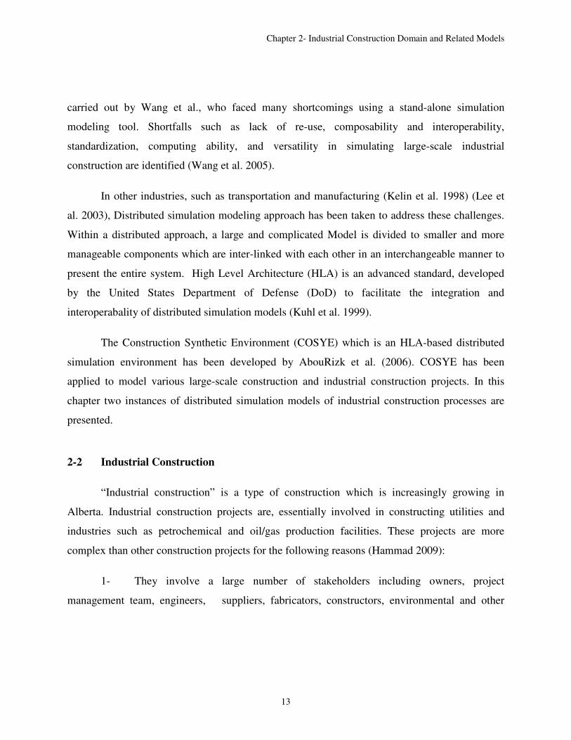
spool fabrication shops, spools are fabricated from pipes and fittings through cutting roll fitting
and welding, position fitting and welding, quality checking, stress relief, hydro testing,
inspection, and painting. The structural steel, pipe spools and other module components such as
mechanical equipment, electrical, and instrumentation cables are shipped to the module assembly
yard and assembled to form a complete module. Subsequently the modules shipped and installed
as a plant module component.
The following section describes in more detail the complexities and constraints in the
industrial construction processes, with a focus on spool fabrication, module assembly, and site
installation. After that, there is an explanation of some of the research that has been conducted on
modeling the industrial construction processes.
2-2.2 Industrial Construction: fabrication, assembly, and site installation
The process of industrial construction is managed by industrial construction contractors.
Their facilities, including fabrication shops and module assembly yards, are not as temporary as
construction site set-ups, and at the same time are not the same as manufacturing shops.
The main difference of industrial construction (Figure 2-2) with building and
infrastructure construction is the complication of industrial construction structures and
uncertainties within construction process. The industrial plants are complex steel structures
formed from the installation of steel structures, pipe spools, and module assemblies. Each of
these products has unique characteristics which make mass production impossible and
complicate the fabrication and module assembly processes.

Chapter 2- Industrial Construction Domain and Related Models
17
Figure 2-2: Typical Production process of Industrial Construction (adapted from Wang, 2006)
Typically, the industrial construction process starts with receiving Isometric (ISO)
drawings from the client. The ISO drawings are redrafted to create fabricable spool drawings
along with detailed information about the welds. The material including the pipes and the fittings
are supplied by the clients or procured by the contractors. The process of fabricating a spool
starts based on its related module assembly priority and the availability of material. After
fabrication, the spools are either shipped to the construction site or to the module yard. At the
module yard, the pipe spool and equipment are assembled on a steel structure as a module.
Finally these modules are shipped to the construction field for the final site installation. In the
following, each process is explained in more detail.
Drafting and Material Procurement:
The spool shop drawings are drafted based on the ISO drawings and other requirements
received from the clients. Along with spool drawings, the bill of material is generated from

Chapter 2- Industrial Construction Domain and Related Models
18
material takeoff. The shop drawings contain detailed information about the job and control
number, and information about the spool specifications such as needed material and welds and
other finishing requirements. The shop drawings are issued to the fabrication shop and are put
into process according to their priority.
Pipe spool materials including pipes and different types of fittings are either supplied or
procured by the clients. Each material has a barcode which makes it trackable through the
process.
Spool Fabrication:
Fabrication shops usually have multiple shops customized for specific materials within
specific range of size and length. Upon receiving the shop drawing, the shop foremen or
superintendents decide on the fabrication sequences and assign different stations which should
perform the cutting, fitting and welding processes on the spool components. This decision is
made in a heuristic manner and mainly based on experience.
Raw materials (e.g. pipes and fittings such as elbows, flanges, and tees) make up the
initial input of the spool fabrication process. These are assembled into spool components and,
finally, the final spool product. The major fabrication operations include cutting, roll-fitting, roll-
welding, position-fitting, and position-welding. First, the raw pipes go through the cutting
process to be cut to the required length according to the shop drawing. According to the
sequencing order, the cut pieces are stored in waiting areas and then along with the related fitting
they are handled to the fitting tables. The fitted joints are then welded together. All the spool
components go through this process until the components of one spool are fitted and welded. At
the final stage of spool composition, based on spool configuration and type of weld, it might
need position fitting and welding. Position fitting and welding are more expensive than roll
fitting and welding, which is why foremen try to minimize the number of position welds in their
sequences. After each round of fitting and welding on spool components, a quality control crew

Chapter 2- Industrial Construction Domain and Related Models
19
reviews the work. Depending on the clients’ specifications, the spool might need to go through
stress relief, hydro-testing, and painting.
Factors such as shop layout, dispatching rules, buffer location, and different production
flows and sequencing order can also affect the fabrication process.
Module Assembly
Fabricated spools are shipped to the module yard assembly. Along with other module
components such as mechanical equipment, and electrical and instrumentation cables, the spools
are assembled on a steel structure to form a module. Delays in spool delivery usually have a
significant effect on the module assembly processes.
The module assembly (e.g., structural steel erection, equipment installation, electrical
work, heat-tracing, insulation, fireproofing, and instrumentation) is done layer by layer. Space
limitation in module yards and multiple involved trades pose many limitations on planning
module assembly yard activities. That is why module yard scheduling is a multi-project resource-
constrained scheduling problem. After assembling the modules, they are shipped to the
construction site for final installation.
Site installation
Site installation refers to all the final installation activities including site preparation,
rough and final grading, pilling, foundations, module installations, electrical and instrumentation
cable wiring, etc. The most challenging process is the modules’ heavy lifting . These heavy lifts
are usually done using mobile cranes. The configuration and allocation of the cranes are
determined based on obstructions in the site, construction sequences, site congestion and many
other factors.

Chapter 2- Industrial Construction Domain and Related Models
20
2-3 Modeling Industrial Construction Processes
A number of modeling attempts have been made to investigate and address the challenges
of industrial construction. Among the modeling approaches used for this purpose are Special
Purpose Simulation (SPS) modeling, distributed simulation modeling, and knowledge discovery
methods.
The following are some models based on SPS modeling:
Song (2004) used a simulation modeling approach to estimate productivity of the
structural steel drafting and fabrication processes. He developed a virtual steel fabrication shop
to assign the products their unique characteristics. Each simulation entity contains product model
features including physical characteristics and also Work Breakdown Structure (WBS) features.
The WBS consists of five levels including division, load-list, drawing, piece, and component
specifications. The modeled fabrication processes consist of drawings detailing process, fitting,
welding, surface preparation, surface protection, and shipping.
Wang (2006) developed a model of pipe spool fabrication to facilitate implementing lean
concepts in industrial construction. He used SPS modeling to compare the traditional batch-and-
queue system with a flow production system in a pipe-spool fabrication shop. He also built a
large-scale simulation model of the entire industrial construction processes in a detailed manner.
However, he faced many limitations using traditional simulation modeling. The shortcomings
included lack of re-use, composability, standardization, computing ability, and versatility in
simulating large-scale industrial construction.
Mohamed et al. (2007) and Taghaddos et al. (2009) devised simulation-based scheduling
for the module assembly process that follows factors such as physical and logical constraints and
different heuristic rules.

Chapter 2- Industrial Construction Domain and Related Models
21
Hammad (2009) investigated improving resources management practices by forecasting
future project needs through analysing existing historical data from completed projects. He built
his framework based on a Knowledge Discovery in Data (KDD) approach with a focus on labour
resources.
As part of the research for this thesis, the author has been involved in couple of industrial
construction modeling projects. Both of these projects are the result of group work and are
modeled in the Construction Synthetic Environment (COSYE), which is based on High Level
Architecture (HLA), a standard that facilitates distributed simulation modeling. The HLA
supports building complex virtual environments representing the real world while allowing any
interaction of computer models, people, and instrumented real equipment.
The first modeling project is the first time that an interactive 3D visualization has been
attached to a large-scale simulation model of the entire industrial construction project.
The second modeling project is an interactive heavy lift model which models mobile
crane heavy lifts in construction sites. The model’s interactive environment makes it suitable for
both modeling and training purposes. Sections 2-3 and 2-4 describe these two projects. Section
2-5 explains what lessons were learned.

Chapter 2- Industrial Construction Domain and Related Models
22
2-4 Distributed Large-scale Industrial Construction Modeling1
2-4.1 HLA based large-scale industrial construction modeling
The stated examples of industrial construction processes show that stand-alone process
interaction models are fully capable of modeling the complicated simulation features of
industrial construction.
However, there is a common drawback to these models; each portion of the industrial
construction process is modeled in isolation, so that the simulation model does not reflect the
effects of dependencies and variations along multiple supply chains. For instance, the start of a
module assembly process is dependent on the delivery of fabricated spools.
The only effort, in construction engineering and management, to simulate the entire
industrial construction process in a detailed manner was carried out by Wang et al., who faced
many limitations using traditional simulation modeling. Shortcomings included a lack of re-use,
composability, standardization, computing ability, and versatility in simulating large-scale
industrial construction (Wang 2006).
In other industries, different approaches have been taken to address these challenges. The
United States Department of Defence (DoD) has developed HLA to facilitate the integration of
distributed simulation models within an HLA environment. HLA allows a large scale model to
be decomposed into a number of smaller and more manageable components (i.e. federates),
while maintaining interoperability between them. In the last decade, HLA has been increasingly
1 A version of Section 2-4 has been published under “Developing Complex Distributed
Simulation for Industrial Plant Construction using High Level Architecture” in Proceedings of
the 2010 Winter Simulation Conference, B. Johansson, S. Jain, J. Montoya-Torres, J. Hugan,
and E. Yücesan, eds

Chapter 2- Industrial Construction Domain and Related Models
23
deployed in a broad range of simulation application areas, including the transportation and the
manufacturing industries (Klein et al. 2010, Lee et al. 2003).
The University of Alberta has developed an HLA-based simulation environment in
construction that is referred to as a Construction Synthetic Environment (COSYE) (AbouRizk et
al. 2009). COSYE has already been applied to model various large-scale construction and
industrial construction projects.
2-4.2 Industrial construction simulation background
These construction simulation tools are effective when the level of abstraction is
manageable. However, the industrial construction process includes drafting, material
procurement and supply, shop fabrication, module assembly, and on-site installation. Using SPS,
it is possible to simulate either a simplified version of the entire process at a high level of
abstraction, or a detailed version of just a portion of the process such as fabrication or module
assembly. The problem with both of these approaches is that they fail to capture
comprehensively and exhaustively the entire industrial construction process. The first approach
(a high level of abstraction) does not include an acceptable level of detail reflecting the product
features and process interactions; the second approach (a detailed version of a portion of the
process) simulates a range of interactive, interdependent processes in isolation from each other.
Both of these approaches result in unanswered questions and vague areas in the planning and
management of construction projects. Moreover, it is unacceptable to claim accuracy of results
and refer management and planning decisions to predicted results based on an incomplete
simulation process.
Wang (2006) pioneered simulating the entire industrial construction process in detail, but
faced many limitations in using SPS. Among the shortcomings he identified are a lack of
knowledge re-use, composability, standardization, computing ability, and versatility in

Chapter 2- Industrial Construction Domain and Related Models
24
simulating large-scale industrial construction. These limitations are addressed by the HLA
system.
HLA was developed in the context of defence applications in the mid-1990s, and then
standardized by IEEE. HLA’s main purpose is to support component-based simulation so that the
development effort is distributed among multiple groups with specific professional interests.
HLA also allows end-users to customize their own combination of simulation components
(federates) from a repository based on their own requirements and interests. The component
models communicate through a Run Time Infrastructure (RTI) using standard HLA-compliant
protocols. HLA supports the interaction of simulation components and facilitates their reusability
and interoperability. The components are independently modeled and executed, and developers
can define their own set of object and interaction classes for data exchange with other simulation
components. This underlying common object model or “interchange document,” is known within
HLA terminology as the Federation Object Model (FOM). According to HLA rules, each
simulation model (federation) should have an HLA Federation Object Model constructed in
accordance with an Object Model Template (OMT) (IEEE 2000.Std 1516.2 2000). OMT
provides a common framework for HLA object model documentation with a standard format and
syntax. However, it is challenging, expensive, and time-consuming to develop a comprehensive
FOM from scratch which fully represents all the involved objects and interactions associated
with the simulation model
The Run-Time Infrastructure (RTI) is the federation’s backbone. It provides software
services such as synchronizations, communication, and data exchange between the federate to
support an HLA-compliant simulation. The COSYE provides a powerful RTI which conforms to
HLA specifications. Employing COSYE facilitates modeling of industrial construction and
overcoming the above-mentioned challenges of traditional construction simulations.

Chapter 2- Industrial Construction Domain and Related Models
25
2-4.3 Industrial construction federation
The current industrial construction federation includes fabrication shop, module yard, and
site manager federates. In addition, some domain-independent federates are designed as
supportive federates to serve one or several federates in the industrial construction federation.
These federates include the calendar, resource allocation, and visualization federates. Figure 2-3
lists the designed federates in the industrial construction federation.
Figure 2-3: Industrial Construction Federation
The following sections briefly explain the industrial construction federation’s FOM and
some of the developed federates. The author has been responsible for technical coordination
between group members and finalizing the FOM and also developing the fabrication shop
federate.
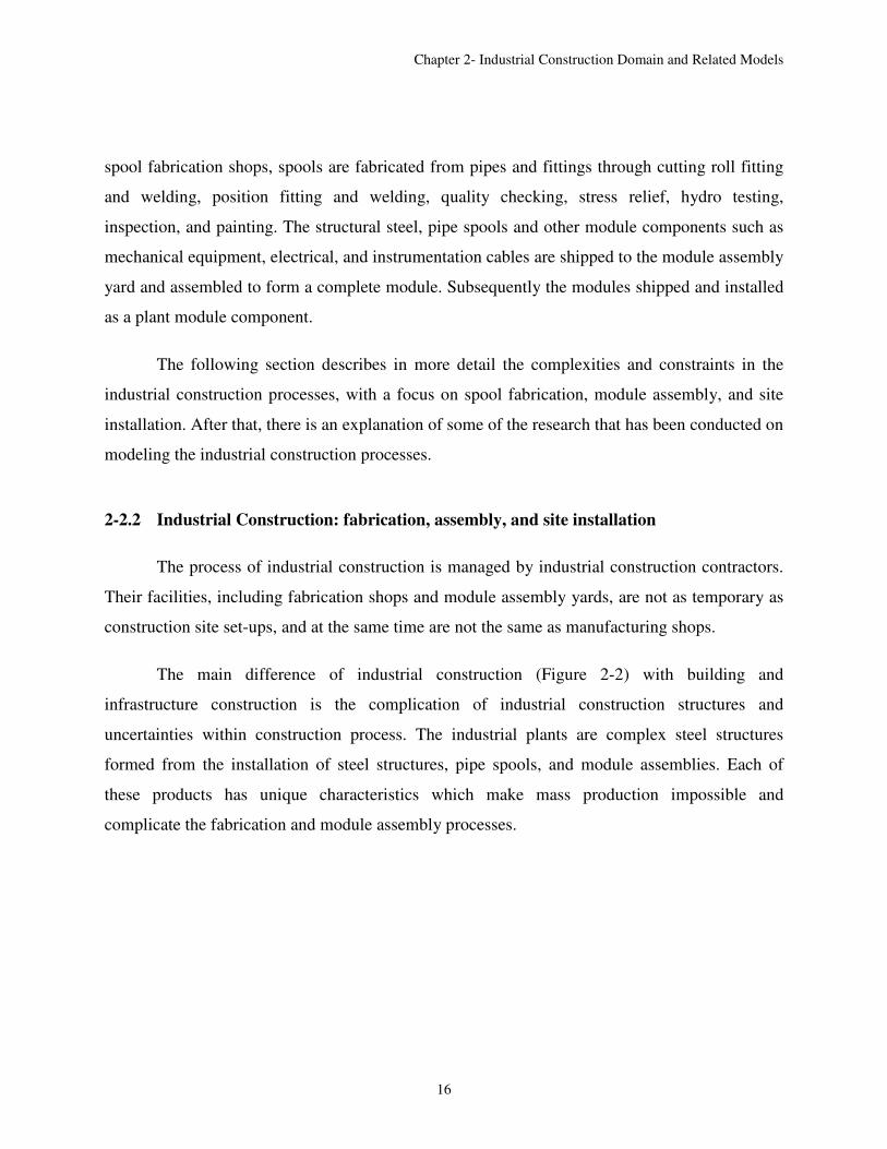
2-4.4 Federation object model of the industrial construction federation
The Federation Object Model (FOM), which is developed based on the Object Model
Template (OMT), provides the interchange document between simulation components. However,
the OMT is not instructive as to how the commonly used and accepted object classes, attributes,

Chapter 2- Industrial Construction Domain and Related Models
26
and interactions might be identified, or whether or not they are semantically comprehensive or
representative of the knowledge domain. In other words, OMT does not offer a methodology that
promises reusable and flexible simulation object model components, limiting the capacity and
capabilities of HLA (Base Object Model Study Group 2006).
Therefore, the FOM should not only follow HLA rules and the Object Model Template
(OMT) but it should also be comprehensive so that it preserves logical connections, both
syntactically and semantically, among the simulation components. For the industrial construction
federation development, the high level construction ontology has been used as the FOM
reference library (explained more in Chapter 4). Figure 2-4-1 and 2-4-2 show different FOM
components for “space” and “module” object classes. These components include different
attributes having different properties regarding their data type and sharing and communication.
The COSYE research team has followed the same ontology throughout various
construction engineering developments in order to increase technical and syntactical
interoperability. Each of these concepts is elaborated for specific federations.
Chapter 2- Industrial Construction Domain and Related Models
27
Figure 2-4-1: Industrial Construction Federation Object Model (FOM)

Chapter 2- Industrial Construction Domain and Related Models
28
Figure 2-4-2: Industrial Construction Federation Object Model (FOM)
2-4.5 Fabrication shop federate
The objective of this federate is to simulate the process of fabricating spools in the
fabrication shop. There are several stations in the spool fabrication shop, including cutting,
fitting, welding, Quality Control (QC) checking, stress relief, hydro testing, painting, and other
surface finishings. Figure 2-5 depicts the typical processes of a spool fabrication shop.
The fabrication shop federate reads the required information about the spools
specifications and different work satiations from the database. Then it simulates the fabrication

Chapter 2- Industrial Construction Domain and Related Models
29
of a spool going through various stations in the fabrication shop. Once all the spools are
fabricated in the shop, the fabrication shop sends a message to the module yard federate giving
the green light to start the assembly process in the module assembly yard.
Cutting
Fitting
Welding
Typical Material Flow Occasional Material Flow
QC Checking
Stress Relief
Hydro Test
Painting / Other Surface Finishing
Shipping to Module Yard or
Construction Field
NDE
NDE
Figure 2-5: Shop Fabrication Process
The spool fabrication federate was initially developed with many simplifying
assumptions. Then the model was evolved to depict the real-world fabrication processes. Chapter
4 describes details of the final spool fabrication federate.
2-4.6 Module assembly federate
The stand-alone simulation models, mentioned in section 2-2, were modified to comply
with HLA rules and are now the module yard federates. In the previous model, all the modules

Chapter 2- Industrial Construction Domain and Related Models
30
were generated at the beginning of the simulation model and scheduled at their Early Start (ES)
time. Now, in contrast, a module in the industrial construction federation is generated at the
fabrication shop federate once all the required spools are fabricated in the spool fabrication shop.
Then the fabrication shop federate updates the state of the module from “Fabrication Shop” to
“Module Yard.” Once this change is reflected to the module yard federate via the RTI, the
federate starts the assembly process at the earlier of either the Early Start (ES) time of the
module or the current time of the module assembly federate.
The most important enhancement in the module yard federate over the previous
simulation models is separating the optimization component as an independent federate, referred
to as the Resource Allocation (RA) federate. All the modules that are looking for space wait in a
queue and determine their utility function over different resource alternatives. This utility
function represents numerous affecting factors in the space allocation problem, including the
modules’ total float, the amount of blocking in a bay because another module in a bay was
delivered late, and the amount of waste space (i.e., not enough to place a module) in a bay
(Taghaddos et al. 2010). Once the RA federate assigns the available resources to the bidding
entity by maximizing the overall utility function (i.e., social welfare), it sends some interactions
to the module yard federate to declare the winning modules. After receiving an interaction from
the RA federate, the modules in the bays schedule an event to capture space. After capturing the
bay, a number of activities (i.e., structural steel, piping, electrical, tracing, insulation) must take
place before a module can be shipped to the site.
2-4.7 Site construction federate
The site construction federate is another main simulation federate designed to simulate
crane operations and modular construction. Once a module is assembled in the module assembly
yard, it is shipped to the construction site by a transporter. Then it has to be lifted to its
predetermined position, once a proper mobile crane in an accessible location with suitable

Chapter 2- Industrial Construction Domain and Related Models
31
configuration and rigging is available and the predecessor modules (e.g., the bottom modules)
are placed in advance. There are also several other constraints in this problem, elaborated in
Taghaddos et al. (2010). The simulation model reads the objects, cranes, locations, pick points,
crane options, and other general information from the database. The information flow of this
federate is described in Figure 2-6. The simulation model considers the cranes, locations and
pick-point as the main resources.
Figure 2-6: Typical site manager process
As in the module yard federate, the simulation model of the site construction federate is
developed based on the standalone simulation model of the site construction. This federate also
takes advantage of the RA federate to allocate the resources optimally to the modules. The bid
price for each module is calculated by approximating the real cost incurred in the construction,

Chapter 2- Industrial Construction Domain and Related Models
32
which is the summation of the actual lifting cost, delay cost and the idle cost of the crane
(Taghaddos et al. 2010).
The other feature of this federate is its connection with the module yard federate. The
arrival time of the modules to the yard depends on the work load and capacity of the assembly
yard. Moreover, the schedule in the yard should be adjusted based on the lifting schedule in the
yard. For example, if a module is delivered to the site and then there is no crane to lift the
module, it has to be shipped again to storage, incurring extra cost for transporting, loading,
unloading and storing. Therefore, it would save on costs if the module was sitting in the yard and
the effort in the yard was put towards another module more urgently needed on the construction
site.
2-4.8 Calendar federate
The main role of this generic federate is to take into consideration national holidays and
long weekends, as well as the number of working hours and overtime hours during the project.
This federate provides a form, shown in Figure 2-7, to input the working hours and overtime
hours during the week. This form also enables the simulator to determine the holidays (e.g., long
weekends) during the project. The calendar federate synchronizes federate time with calendar
time. Thus, all federates that are interested in advancing time according to the calendar can
register for this federate’s updates.
Figure 2-7: Calendar federate

Chapter 2- Industrial Construction Domain and Related Models
33
2-4.9 Resource allocation federate
This federate is designed to act as an auctioneer to allocate resources among the bidding
agents. In other words, this federate is supposed to solve the Winner Determination Problem
(WDP) in the combinatorial optimization. Currently this federate can allocate two types of
resources (crane and location) to a number of bidding agents based on a greedy algorithm or
ascending-auction algorithm. This federate can easily be expanded to allocate n type of resources
to several agents using a combinatorial optimization. Figure 2-8 shows the schematic view of
communication between the RA federate and other simulation federates (e.g., module yard
federate) in the industrial federation. Initially, this federate operated through a database, but
currently it works through interaction. This federate currently works with the module yard
federate as well as the site construction federate.
The RA federate is called from the module yard federate on a regular basis to maximize
the bidding agents’ social welfare. Moreover, the module yard federate inherits from the
Resource Allocation Base (RAB) federate to automate its communication with the RA federate.
Figure 2-7 shows results in the RA federate for one of the site construction auctions.
Figure 2-8: Communication between RA and simulation federates

Chapter 2- Industrial Construction Domain and Related Models
34
2-4.10 Visualization federate
The visualization federate helps to visualize the assembly process in the module yard as
well as in the site interactively, while the module yard and site construction federates are
running. This federate provides the different parties a common understanding of the field
processes and operations. This federate is developed using Blender, an open source environment
that can be integrated with the .NET framework. The Blender gaming engine updates a module
location after receiving the respective message from the site construction simulation. The Site
Viewer federate then sends reflected attribute values to the visualization model, which
automatically updates the site during run time, putting each module in its predefined location.
This federate has been recently replaced by a 3D visualization federate, which is under
development (Figure 2-9).
2-4.11 Summary of industrial construction project
Within the COSYE environment, large-scale industrial construction was decomposed into
several federates developed by different individuals based on their interest and expertise.
Figure 2-9: 3D visualization of site installation

Chapter 2- Industrial Construction Domain and Related Models
35
Decomposition saves development time and effort and helps the developer to focus on a portion
of the process, while the interaction with other industrial construction federates ensures
comprehensive simulation of the entire industrial construction. Decomposition also makes it
easier to reuse other simulation components: supportive federates such as calendar can be built
once and reused with other federations interested in the same functionality. Also, because
decomposition happens both on a development and execution level, the execution of simulation
components on different engines provides sufficient computing capacity to execute the entire
federation.
This decomposition also allows independence of the federates. Each of the industrial
construction federates, according to their needs, could use different simulation world views with
different time scales. In industrial construction, mostly the process-interaction discrete event
simulation world view provided by Simphony.NET services was used; however, for resource
allocation, the federate agent-based simulation was employed. With regard to the time scale, in
the shop fabrication process, the task duration might be on the order of seconds; however, in
other federates larger time scales have been used. As may be imagined, this eases development
considerably.
2-5 Heavy-lift Interactive Federation2
In construction, heavy lifting is widely used for module installation or replacement, or
installing other pieces of equipment. For this purpose, mobile cranes are commonly utilized in
North America and they become critical resources for construction sites. In addition, mobile
cranes locate at different places with different configurations for servicing different construction
2 Section 2-5 has been submitted for the course project “Advanced Topics in Construction
Engineering and Management: Advanced Simulation” Spring term 2010. Instructuor: Dr. Yasser
Mohamed. Students:Jangmi Hong, ManaMoghadam, Chunxia Li, Fayyad Sabha, Ronald
Ekyalimpa, Carlos V. Gonzalez. Teaching Assistants: Di Hu, Farzaneh Saba.

Chapter 2- Industrial Construction Domain and Related Models
36
sequences while considering other factors such as site obstructions and congestion. By
interviewing several lift experts, Varghese et al. (1997) identified lift criteria for lift planning:
availability of the crane, access to site, access to lift area, crane location, lift path clearances and
safety factors, ground support during lift, and removal from lift area. These criteria can be used
for evaluating the lift’s feasibility. These feasibilities are influenced by other factors such as
crane type, crane configuration, site layout, and construction sequence or schedule.
The heavy lift interactive federation was originally developed as a graduate level course
(Advanced Topics in Construction Engineering and Management: Advanced Simulation) project.
The HLA implementation described here was mainly a training exercise for graduate students
learning about distributed simulation and HLA for the first time. The main objective was to
define the problem in a way that magnifies the most important capabilities of a distributed
simulation approach. Students were divided into five groups and assigned the development of
one federate in the federation. The author was one of the teaching assistants and involved in
developing one of the federates (Player federate). The gaming and interactive aspects of the
federation provided a medium for the student to learn and explore the capabilities of the
distributed simulation framework. The development of the federation was completed after
several cycles of developments in the class.
2-5.1 Federation description
The project was proposed to simulate the process of crane selection and crane operation
for lifting and placing modules at industrial construction sites. The project considers factors such
as crane availability and suitability, and crane operating time and related costs, as well as module
storage consideration. Also, the project supports decision-making for the user by providing
certain options with detailed information. The user can place lift orders based on the information.

Chapter 2- Industrial Construction Domain and Related Models
37
According to the project scope’s function requirement, the whole federation is made up
of four federates:, lift scenario generation federate, player federate, operation simulation federate
and an auxiliary federate, which is the visualization federate (Figure 2-10).
This federation’s purpose is to serve as a training tool at the university and industry in the
subject area of designing and analyzing mobile crane operations in the construction domain. The
scenario federate, player federate and operations federate were the core federates for this project.
The tool was designed such that it has one administrator and a number of players running it
simultaneously on different computers (as a distributed simulation). Typically, the administrator
would control the scenario federate and the operations federate while the players/trainees would
use/interact with the player federate. The administrator would generate input (crane & module
instances and lift options) for the federation. This would serve as input to the player(s). The
player(s) would select which modules would be lifted by which cranes and which would be sent
to storage. Player selections would be sent to the operations federate as lift orders that would
then be processed by the operations federate. The player would then get to view the
results/implications of the decisions he/she made in terms of cost and time.
Operation federate is a discrete event simulation federate for simulating the lifting
operations and estimating their time and cost. This federate will subscribe lift orders from the
Figure 2-10: Heavy lift federation

Chapter 2- Industrial Construction Domain and Related Models
38
player federate and take it as the main entity in the whole federate. It will make the crane and
crane location in the lift object resources. The crane resource availability depends on the lift
scenario federate. This federate keeps track of crane’s current location and configuration and will
change (configuring, moving, rigging, and lifting) these based on the requirements of the coming
orders. It will also publish information regarding the crane resource’s queue length and current
locations, as well as the finished orders and the time they were finished. In addition, it will
update information about the project’s overall cost and time.
The lift scenario federate (2-11) is a scaled time-stepped federate. It is responsible for
generating modules and lift options for modules for this time step and also the ones that are for
the next period. While considering the difficulty parameter, the actual arrival at a certain period
may be varied from previously forecasted ones. The crane availability or available period is also
controlled in this federate and can be modified based on a difficulty factor.
Figure 2-11: Lift Scenario Federate
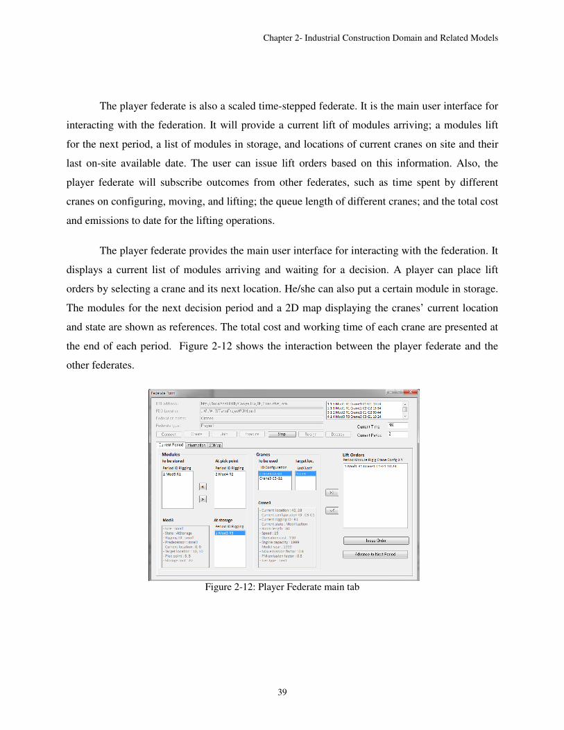
Chapter 2- Industrial Construction Domain and Related Models
39
The player federate is also a scaled time-stepped federate. It is the main user interface for
interacting with the federation. It will provide a current lift of modules arriving; a modules lift
for the next period, a list of modules in storage, and locations of current cranes on site and their
last on-site available date. The user can issue lift orders based on this information. Also, the
player federate will subscribe outcomes from other federates, such as time spent by different
cranes on configuring, moving, and lifting; the queue length of different cranes; and the total cost
and emissions to date for the lifting operations.
The player federate provides the main user interface for interacting with the federation. It
displays a current list of modules arriving and waiting for a decision. A player can place lift
orders by selecting a crane and its next location. He/she can also put a certain module in storage.
The modules for the next decision period and a 2D map displaying the cranes’ current location
and state are shown as references. The total cost and working time of each crane are presented at
the end of each period. Figure 2-12 shows the interaction between the player federate and the
other federates.
Figure 2-12: Player Federate main tab

Chapter 2- Industrial Construction Domain and Related Models
40
The visualization federate is a time-stepped federate. It is for visualizing the crane and
module movement. This federate has its own time advancement mechanism. But it needs to
reflect the crane information and module information from other federates. The crane ID will be
subscribed from the lift scenario federate. Its Current Location coordination will be subscribed
from the operation federate. Figure 2-13 shows the logic behind the federate.
Figure 2-13: Flowchart of Visualization Federate Logic
In this part, several snapshots of the visualization federate are presented. Figure 2-15 is a
snapshot of the site layout before the simulation, and Figure 2-16 is a snapshot of the real time
visualization of simulation results.

Chapter 2- Industrial Construction Domain and Related Models
41
Figure 2-14: Site layout and marker distribution
Figure 2-15: Snapshot of real time simulation – visualization result
2-6 Lessons Learned
Comparison between SPS and HLA-based distributed modeling:
Chapter 2- Industrial Construction Domain and Related Models
42
• SPS easiness vs. complexity of distributed modeling: SPS modeling tools such as
Simphony are much easier to learn compared to HLA-based distributed modeling. SPS
tools usually come with a library of reusable components which facilitates model
development. That is why, for quick modeling of the construction process, SPS is the
optimum means and the reason it has been easier to persuade industry to use SPS tools.
• Monolithic vs. distributed: SPS tools keep all information within one model; however, in
distributed modeling, decomposed models and information can be located from
geographic disperse locations.
• Static vs. dynamic: In SPS tools, once the simulation starts neither the model nor the
input information can be changed. But in distributed modeling during runtime,
information can be dynamically received by the federates. This feature makes distributed
models interactive; for instance, in the industrial construction federation, the user can
dynamically change the construction site input data using the visualization federate. The
federation is able to re-simulate the process based on the changed input information.
• Single application vs. multi-application: The SPS tools’ function is exclusively process
modeling. However, in distributed modeling it can be used for a wide range of varying
applications. One of the most important, through the interactive nature of distributed
simulation, is for training purposes. The heavy lift interactive federation, which was
discussed earlier, can be used for training purposes.
In addition to many advantages, distributed simulation modeling has its own special challenges.
The most important is coordination between all the involved groups. Here are some approaches
that helped us to lessen the challenge while developing the “industrial construction” and “heavy
lift” federations.
• Defining a clear project scope:
o Modeling problem and objectives
o Project scope should be finalized with members from all groups present..

Chapter 2- Industrial Construction Domain and Related Models
43
• Uniformity and Consistency in Model Representation
o Such as consensus on the most important one-time scale of all the scales being
used.
• Proper decomposition of model
• Developing a comprehensive FOM
With proper decomposition, each involved party knows their requirements (e.g., subscribing
object classes, attributes, interactions, parameters) from other federates and also deliverables to
other federates’ requirements (e.g. publishing object classes, attributes, interactions, parameters).
The changes in FOM should be minimized by developing a comprehensive FOM; however
sometimes changes are inevitable.
All the parties should be updated on any changes. We kept track of these by setting up an online
spreadsheet (Table 2-1) expressing the interest of all federates and updating all the group
members via email in case of any changes and special requests from other federates.
• Independent development through testing federates:
Through the process of federates’ construction, the developers should be able to independently
follow the development process. This is possible by using temporary test federates, which play
the role of the other federates’ interface. These test federates provide the FOM components to
which the developing federate has subscribed in accordance with the agreed time management.
Also, there are federates which play the role of recipient federates, receiving the message that the
developing federate is publishing.
Within this approach all the participants can go through the development process without being
held back by waiting for other groups’ development. Through different stages of development,
testing sessions were set up. Through testing sessions, groups would give a report on their
progress and the challenges they were facing. Also, the entire federation components were linked
together so that the federation performance could be tested.

Chapter 2- Industrial Construction Domain and Related Models
44
This way of approaching distributed simulation modeling in the COSYE environment, facilitates
more efficient development process.
Table 2-1: FOM shared spreadsheet

Chapter 2- Industrial Construction Domain and Related Models
45
For instance, developing a comprehensive FOM from scratch, which fully represents all the
involved objects and interactions associated with a simulation model is challenging, expensive,
and time-consuming. That is why, in Chapter 4, an alternative method is suggested to extract
FOMs from ontologies that represent formalized construction domain knowledge. Industrial
construction domain knowledge is captured in InCon ontology and the FOM is extracted from
the ontology through semantic query languages.
Moreover, in the industrial construction federation and heavy lift interactive federation,
explained in this chapter, the COSYE federates were developed by writing C# or Visual Basic
code within the Visual Studio environment. This makes the development process in COSYE
difficult when compared to a visual modeling environment such as Simphony. In Chapter 4,
component-based simulation modeling in the COSYE environment is pursued. The idea is to
create a set of modeling elements that provide access to the various HLA services and simulation
modeling services. This approach facilitates developing simulation modeling through reusing
modeling elements. Chapter 4 focuses on characteristics of these modelling elements and
suggests an ontology-driven approach towards developing them.
2-7 References
AbouRizk, S. 2009. “Framework for Highly Integrated, Interoperable Construction Simulation
Environment” , Paper presented at the International Conferonce on Construction
Engineering and Management/Project Management (ICCEM.ICCPM), Juju, Korea.
Gupta, V. K., Chen, J. G., and Murtaza, M. B. (1997). "A learning vector quantization neural
network model for the classification of industrial construction projects." Omega, 25(6), 715-
27.Schimmoller 1998
Hammad, A. 2009 “An Integrated Framework for Managing Labour Resources Data in Industrial
Construction Projects: A Knowledge Discovery in Data (KDD) Approach”, University of
Alberta, Edmonton, Canada

Chapter 2- Industrial Construction Domain and Related Models
46
IEEE 2000. Std 1516.2. 2000. Standard for modeling and simulation (M&S) high level
architecture(HLA)- object model template (OMT) specification.
Klein, Ulrich, Thomas Schulze, and Steffen Strassburger. 1998. Traffic simulation based on the
high level architecture. Proceedings of the 30th conference on Winter simulation: 1095 - 1104
Lee, Jong-Keun, Min-Woo Lee, and Sung-Do Chi. 2003. DEVS/HLA-based modeling and
simulation for intelligent transportation systems. Simulation 79 (8) (August 01): 423-39.
Mohamed, Yasser, Davila Borrego, Luis Francisco, Mohamed Al-Hussein, Simaan Abourizk,
and Ulrich Hermann. 2007. Simulation-based scheduling of module assembly yards: Case
study. Engineering, Construction and Architectural Management 14 (3): 293-311.
SISO. (2006). “BOM template specification”. SISO-STD-003-2006.
Song, L., Wang, P., and AbouRizk, S. (2006). “A virtual shop modeling system for industrial
fabrication shops.” Simulation Modeling Practice and Theory 14(5), 649-662.
Taghaddos, H., AbouRizk, S. M., Mohamed, Y., and Hermann, U. (2010). "Simulation-based
multiple heavy lift planning in industrial construction." Construction Research Congress
2010: Innovation for Reshaping Construction Practice - Proceedings of the 2010
Construction Research Congress, 349-358, 2010
Taghaddos, H., S. AbouRizk, Y. Mohamed, and R. Hermann. 2009. “Integrated simulation-based
scheduling for module assembly yard”. Proceeding of the 2009 Construction Research
Congress, 1270-1279
Varghese, K., Dharwadkar, P., Wolfhope, J., and O’Connor, J. T. ~1997, “A heavy lift planning
system for crane lifts.” Microcomput. Civ.Eng., 12, 31–42.
Wang, P., Mohamed, Y., and AbouRizk, S. M. (2005). "Production-based large scale simulation
modeling for construction projects", 33rd CSCE Annual Conference 2005, Canadian Society
for Civil Engineering, Montreal, H3H 2R9, Canada, Toronto, ON, Canada, CT-118-1-CT-
118-11.
47
Chapter 3
Ontological Conceptual Modeling of Industrial
Construction Processes to Enhance
Interoperability and Reuse
3-1 Introduction
In response to the increasing complexity of construction systems, the development of
sophisticated methods and tools for the modeling and analysis of these systems is needed.
Simulation has been a formal topic in construction engineering research for almost three decades,
but still has not been embraced as a practical tool in the industry. One of the primary reasons for
this lack of research transfer is that building simulation models needs significant amount of
knowledge and data acquisition. Moreover the process of building a simulation model is very
time consuming and costly which is a drawback for industry to use simulation as a useful tool.
The reuse of simulation components is a key feature for cost-effective development.
Although many construction simulation approaches currently allow for the reuse of previously
developed components (Hajjar et al. 2000; Oloufa 1993) and provide libraries of such

Chapter 3- Ontological Conceptual Modeling of Industrial Construction Processes to Enhance Interoperability and
Reuse
48
components, still reuse of earlier developments is not a common practice because of lack of
effective traceability and communication in constructing simulation models.
Documenting and formal conceptual modeling in structural manner enhances the quality
and efficiency of simulation development and also it is a potential way to capture and share the
knowledge within simulation models.
3-2 Conceptual modeling
In Modeling and Simulation (M&S), modeling focuses on purposeful abstraction of the
real world model (Zeigler 1976) and simulation relies on implementing models (Tolk 2007). The
modeling part in the M&S community is usually known as conceptual modeling. According to
Robinson (2006), a conceptual model is “a non-software specific description of a simulation
model that is to be developed, describing the objectives, inputs, outputs, content, assumptions
and simplifications of the model”. Figure 3-1 depicts the relationship between the real world,
conceptual model and simulation model.
Conceptual modeling is known as the most important aspect of a simulation project;
however, it is the least understood part and in most simulation developments, it is missing. There
have been attempts to provide a guideline for developing a conceptual model. Shannon (1975)
describes four steps as follows:
1- Specification of the model’s purpose.
2- Specification of the model’s components.
3- Specification of the parameters and variables associated with the components.
4- Specification of the relationships between the components, parameters, and variables.

Chapter 3- Ontological Conceptual Modeling of Industrial Construction Processes to Enhance Interoperability and
Reuse
49
Figure 3-1: Simulation project life-cycle (adapted from Kotiadis and Robinson, 2008)
The presentation and documentation of conceptual models is another area of developing
conceptual models that has yet to be investigated; in many cases, there is no documentation at all
other than the use of diagramming techniques such as process flow diagrams and event graphs
(Robinson 2004). But documenting and formalizing conceptual models in a structural manner
not only enhances the quality and efficiency of simulation development, it also enhances the
potential reuse of the captured knowledge within conceptual models.
In the military domain, conceptual modeling and its documentation has been investigated
more than in any other domain. Military simulations often involve large-scale models which lead
to more interest in the structure documentation of conceptual models and their reuse (Robinson
2006). The Base Object Model (BOM) is a Simulation Interoperability Standards Organization
(SISO) standard conceptual modeling documentation. Thus, BOM portrays the necessary
information about the simulation model, the simulation model’s components including events
and entities and the behavior of simulation components such as a pattern of interplay and the
entities’ state. This information is leveraged into BOM meta-data (Gustavson and Chase 2007).
In the following BOM, the components are described; its meta-data represents the model
identification, conceptual model definition, model mapping, object model interface and
interaction classes (Figure 3-2).

Chapter 3- Ontological Conceptual Modeling of Industrial Construction Processes to Enhance Interoperability and
Reuse
50
Figure 3-2: The BOM structure (adapted from BOM standard, 2006)
- Model Identification: This part of the BOM contains the general information about the
BOM.
- Conceptual Model Definition: The BOM conceptual model definition provides the
pattern of interplay, the state of an entity, the entity types, and event types.
- Model Mapping: In model mapping, existing entities and event relationships are
presented in the abstract, so that the conceptual model has the potential to be mapped to the
actual simulation model.
- Object Modeling Definition: The object model definition represents the interface of the
conceptual model.
Some studies have been conducted with the aim of carrying BOMs forward as simulation
components through the development process and composing models from BOMs (Moradi
2007).
3-2.1 Conceptual modeling and model reusability
The first step towards reusing other people’s models, is understanding their development.
However, in the current practice the conceptual model usually just exists in the developer’s mind

Chapter 3- Ontological Conceptual Modeling of Industrial Construction Processes to Enhance Interoperability and
Reuse
51
and even if captured it is in loose forms which do not reflect enough of the model. Lack of
proper communication and traceability of the models’ content leads to less reuse of simulation
models.
A conceptual model is similar to a communication bridge, connecting real world to
computer model. Proper documentation of conceptual models helps with understanding the
model and increases the likelihood of reusing the simulation model; however there is not any
common documentation method in the simulation community.
3-2.2 Conceptual modeling and modeling composability
Interoperability is traditionally referred to technical interoperability; however, according
to Tolk (2007), the term interoperability for systems means the ability to communicate
effectively both syntactically and semantically. The following is a more detailed definition for
these terms:
- Interoperability addresses software and implementation details of systems interoperation
such as data exchange. More specifically, in M&S it deals with simulation implementation and
execution.
- Composability, on the other hand, deals with the alignment of concepts on the modeling
level. Composability is concerned with the alignment of conceptual models, which are the
underlying abstractions of reality in simulation models.
Tolk and Muguira (2003) suggest a hierarchy for different levels of models’
interoperability in the M&S community (Figure 3-3).
Technical interoperability: communication technology infrastructure, which is concerned with
exchanging bits and bytes.

Chapter 3- Ontological Conceptual Modeling of Industrial Construction Processes to Enhance Interoperability and
Reuse
52
Syntactic interoperability: using common data structures for exchanging data and using common
protocols.
Semantic interoperability: using common references in order to understand the meaning of data
and their association between concepts and the real world.
Pragmatic interoperability: understanding the intent of using data when systems, simulations, or
applications are involved.
Dynamic interoperability: understanding the effects of exchanging data in sending and receiving
services, which happens through using common execution models.
Conceptual interoperability is achieved when all involved groups understand, with no ambiguity,
the capabilities and constraints of simulation models.
In the following ontologies are introduced as the proper means for documenting
conceptual models.
Figure 3-3: Levels of conceptual interoperability model (adapted from Tolk and Muguira, 2003)

Chapter 3- Ontological Conceptual Modeling of Industrial Construction Processes to Enhance Interoperability and
Reuse
53
3-3 Ontologies and Conceptual Modeling
The term ontology means an “explicit specification of a conceptualization” (Gruber
1995). A conceptualization provides an abstract view of the real world. Simulation models are
knowledge-based models, explicitly or implicitly committed to conceptualization. Following the
definition of ontology, we believe that ontologies are the best means for documenting the
conceptual models and dealing with reusability and interoperability challenges of simulation
models.
Within ontologies, what is captured is a formalized understanding of the domain
conceptualization which declares the domain’s specifications and the assumptions made towards
developing the simulation models. Therefore, the ontology of a domain facilitates analysis of
domain knowledge and improves the reuse and interoperability of systems that are built based on
it (Uschold and Gruninger 1996).
The spectrum of ontological semantics goes from weak semantics to strong. The
semantics are improved by increasing the meta-data to capture more information. Figure 3-4
describes different categories of semantic representation from weak to strong semantics (Obstr
2006). Each category can be explained as follows:
Data dictionaries: This category has the weakest semantics and contains the “terms” used in the
domain.
Thesaurus and Taxonomies: The thesaurus category evolves as equivalence, homographic,
hierarchical, and associative relationships among terms are indentified. Taxonomies contain a
higher level of semantics because of having a structured classification.
Data models: Compared to lower level categories, this category is enriched in pragmatics and
semantics but still falls under semi-formal or semi-informal ontologies.

Chapter 3- Ontological Conceptual Modeling of Industrial Construction Processes to Enhance Interoperability and
Reuse
54
Ontologies: Ontologies are not just hierarchical structures containing all the entities. In addition
to entities, ontologies present the relationships between the entities and the rules governing the
domain knowledge.
Logical models: Logical models are semantically the strongest in this category. Logical
expressions are explicitly specified through axiomatic approaches.
Data Dictionaries
Semantics
Taxonomies and Thesaurus
Data Models
Ontologies
Logical Models
Degree of Complexity
Terms
Relational models, XML
DB Schema XML Schema
Data models, UML
Formal
Taxonomies
Conceptual models
Descriptive Logic
Semantic mapping
Figure 3-4: Ontological spectrum (adapted from Obstr, 2006)
3-4 Methodologies for Ontology Development
Ontology includes the taxonomy of concepts and their properties and an indication of
how concepts are inter-related, which collectively impose a structure on the domain. The shared
understanding of the domain through ontologies facilitates the domain’s accurate and effective
communication, which leads to benefits such as models’ composability and reuse (Uschold 98).
There is no single method for developing domain ontologies. However, still there are
various guidelines for ontology design and development. As an example, Uschold and Gruninger
(1996) present a five-phase methodology as follows:

Chapter 3- Ontological Conceptual Modeling of Industrial Construction Processes to Enhance Interoperability and
Reuse
55
1- Identify purpose and scope: Identifying the scope, purpose, intended use of ontology, and
the targeted user.
2- Building the ontology:
a. Ontology capture: Identifying the most important concepts and relationships in
the domain of interest. Identifying the terms to refer to the concepts and
relationships.
b. Coding the ontology: Explicitly representing the knowledge capture in the
previous phase using ontology representation languages such as Web Ontology
Language (OWL) or Resource Description Framework (RDF).
c. Integrating existing ontologies: Using existing ontologies if appropriate.
3- Evaluating the Ontology: Evaluating the ontology with respect to defined requirements.
The requirements can be captured through competency questions.
4- Documentation
5- Guidelines for each phase
Uschold and Gruninger’s methodology is followed in this research for developing an
Industrial Construction Ontology (InCon-Onto).
3-5 Industrial Construction Ontology (InCon-Onto) Development
3-5.1 Purpose and scope of InCon-Onto
The purpose of InCon-Onto is to provide a proper formalization of the industrial
construction processes. This documentation is human understandable and also computer
interpretable. The industrial construction processes are structured based on process modeling

Chapter 3- Ontological Conceptual Modeling of Industrial Construction Processes to Enhance Interoperability and
Reuse
56
principals. So that the knowledge within them can be deployed in different process oriented
modeling application.
The industrial construction processes are modeled through the following specifications:
- The ontology presents the industrial construction domain through concepts and the
relationships amongst them.
- The set of classes arranged in hierarchal taxonomy represents the domain concepts.
- The concepts’ hierarchy represents the concepts starting from general concepts
decomposing into specialized concepts.
- The ontology represents the industrial construction processes and their characteristics.
- The ontology represents the related concepts around the industrial construction processes
along with the properties.
- The ontology represents relationships between the processes and other related concepts.
- In construction, the pattern of process is captured through process modeling.
3-5.2 Building the InCon-Onto
3-5.2.1 Ontology capture
The next sections explain our approach towards capturing the industrial construction
abstract picture. We start by introducing the 5Ws (who, what, where, why, when), which is a
very general abstraction method used in journalism and literature. We then move into process
modeling to abstract industrial construction process. In order to get familiar with the process of
classification and the decomposition of process, we probed some other existing ontologies in
similar domains such as construction and manufacturing.

Chapter 3- Ontological Conceptual Modeling of Industrial Construction Processes to Enhance Interoperability and
Reuse
57
3-5.2.2 Capturing InCon-Onto
Using models to structure the acquired knowledge from domain experts and other sources
reduces complexity, improves communication and enhances our understanding of the domain. A
very general and basic method for understanding a task is the 5Ws (wikipedia):
1- Who is accomplishing the task?
2- What task must be accomplished?
3- Where is the task performed?
4- When is the task done?
5- Why is the task done?
When it comes to construction processes, the 5Ws can be expressed within process
modeling concepts (Figure 3-5):
Figure 3-5: Process modeling correspondence to 5Ws
According to Kawalek (2004), process modeling refers to a collection of techniques used
to portray the behavior of systems. The industrial construction process expressed within process
modeling concepts can now become formalized within machine-readable ontology
representation.

Chapter 3- Ontological Conceptual Modeling of Industrial Construction Processes to Enhance Interoperability and
Reuse
58
3-5.2.3 Integrating existing ontologies
Many domains have started developing ontologies in their fields. The construction
research community has also joined the stream to convey advantages to the community.
Construction ontologies have been developed to allow domain users to share, in a structured
manner, a common understanding of the information in the construction domain. These
ontologies allow for the reuse of domain knowledge as “reference libraries”, which is extensible,
and its future growth is possible. Ontologies can be modified when necessary and used by
different applications. Very few projects have been undertaken to formalize the construction
domain within ontologies. The existing ontologies are more focused on building industry and
project management aspects of construction engineering. The following are instances of these
ontologies, which have mostly been developed in Dr. El- Diraby’s research group at the
University of Toronto:
- IC-PRO-Onto: an Infrastructure and Construction PROcess Ontology (El-Gohary and El-
Dibary 2010)
- BCTaxo: a semantic representation of the building-construction knowledge-supporting
ontology-based corporate memory system (El-Diraby and Zhang 2006).
- HiOnto: a distributed highway ontology (El-Diraby and Kashif 2005).
- OSPTaxo: an ontolgy for outside plant construction in telecommunication infrastructure
(El-Diraby and Briceno 2005).
- S2HOnto: provides ataxonomy for stakeholder management and sustainability in the
domain of urban highway construction (El-Diraby and Wang 2005).
All of these ontologies are built based on a fundamental process-modeling ontological
concept which is: actors are involved in the processes that are part of a project. Such processes

Chapter 3- Ontological Conceptual Modeling of Industrial Construction Processes to Enhance Interoperability and
Reuse
59
utilize resources according to a mechanism; however, they are constrained by constraints. (El-
Diraby et. al 2003)
Another domain which has much in common with industrial construction is
manufacturing. Both combine discrete processes updating the status of a product until it satisfies
required specifications. Exploring manufacturing ontologies such as Manufacturing Semantically
Ontology (MASON) (2006) shows again that the process modeling approach has been used to
develop a manufacturing ontology. For instance, MASON ontology follows Martin and Dacunto
(2003), who describe the manufacturing domain as the sum of “product, process and resource
concepts.”Table 3-1 shows the major concepts used in some construction and manufacturing
ontologies.
Table 3-1: Major concepts used in some construction and manufacturing ontologies
Construction Ontology Manufacturing Ontology Industrial Construction Ontology
IC-PRO-Onto (2010) MASON (2006) InCon-Onto (2011)
Project
Actor
Product
Process
Resource
Constraint
Mechanism
Attribute
Modality
Family
Entity
Operation
Resource
Process
Product
Resource
For InCon-onto, in order to keep the main structure as simple as possible, the main
industrial domain concepts have been chosen to be “process, resource and product”. (Figure 3-6)
In developing an Industrial Construction Ontology (InCon-Onto), the ontologies which were
named in table 3-1 have been studied and the concepts and relationships which seem to suit the

Chapter 3- Ontological Conceptual Modeling of Industrial Construction Processes to Enhance Interoperability and
Reuse
60
industrial construction domain have been adapted to InCon-Onto. As was mentioned, InCon-
Onto was developed based on process modeling concepts. In the concepts’ classification and
decomposition, the previously mentioned process modeling ontologies are followed.
Figure 3-6: InCon-Onto top level concepts and relationships
The main ontological model followed within industrial construction concepts of InCon-
Onto is the following: the processes utilize the resource to produce or update a product; the
process is performed by a human resource using an operational resource and taking place at a
geographic resource, the process takes a product as an input and after updating the product’s
status delivers it as its output and the output moves to next process. For example a fitting has
parts or spool assemblies as input, is performed by a fitter, requires a welding machine as a tool,
and takes place at a fitting station.
3-5.3 Industrial construction ontology coding
Ontologies can be encoded using a variety of semantic web languages. The most well-
known are RDF and OWL semantic web languages recommended by World Wide Web
Consortium (W3C) since 2004.

Chapter 3- Ontological Conceptual Modeling of Industrial Construction Processes to Enhance Interoperability and
Reuse
61
The evolution of semantic web languages started with the use of XML. XML goal, in
contrast to HTML, is to store and carry information. XML is a simple yet flexible markup
language which with the use of meaningful tags, it is able to convey more semantics than HTML
(W3C 2008).
Within Resource Description Framework (RDF) instead of fixing what data can be
captured, the description of data is enriched. RDF makes statements about the resources, in the
form of triples, indicating their properties or relationships. Triple expressions are composed of
subject-predicate-object. The subject is a resource which is in a relationship with another
resource (object) through the predicate. RDF collection is organized through RDF Schema,
which is a set of classes with certain properties which provide basic elements to describe
ontologies. But RDF Schema does not provide exact semantics for representing complex
constraints (W3C 2004).
The W3C has approved OWL as another standard language for encoding ontologies. It
incorporates and enhances its predecessors’ interoperability features (RDF, RDF-S, DAML,
DAML+OIL). Compared to RDF-S, OWL provides more vocabulary for describing classes (e.g.,
disjointness), properties, and relationships (e.g., symmetry, transitivity) (Figure 3-7) (W3C
2009).
OWL comes in three different expressiveness degrees: OWL Lite, which has
expressiveness similar to that of RDF-S; OWL DL, which is based on description logics which
are computationally complete and decidable; and OWL Full, which provides additional features
but does not guarantee finite computation (McGuinness and Harmelen 2003).

Chapter 3- Ontological Conceptual Modeling of Industrial Construction Processes to Enhance Interoperability and
Reuse
62
Figure 3-7: Semantic web language evolution
InCon-Onto is encoded in OWL DL and was developed using Protégé 2000
(protege.stanford.edu) and TopBraid Composer, which has its roots in Protégé OWL.
(Knublauch 2006). InCon-Onto has been formulated in OWL/RDF bundled with the Protégé
platform. The editor comes with different types (e.g. import, export, validation, visualization…)
of plug-ins (Storey et. al 2001).As figure 3-8 shows industrial domain ontology includes three
representation levels: underlying knowledge representation level, ontology concept level and the
instance level. The ontological knowledge level consist of object classes, data properties and
axioms. At the ontology concept level all the domain specific concepts, attributes and
relationships are defined. The concepts are divided to general process modeling concepts and
specific domain concepts. This allows all the mapping rules to be based on general process
modeling concepts while at the same time covering specific domain concepts. The concepts are
grouped in hierarchies to simplify understanding domain concepts and the relationships define
how the concepts become connected.

Chapter 3- Ontological Conceptual Modeling of Industrial Construction Processes to Enhance Interoperability and
Reuse
63
Figure 3-8: Different levels of Industrial Construction Ontology
The ontology structure consists of five major components as follows:
1- Classes represent domain concepts arranged in hierarchy
2- Instances or objects belong to classes
3- Properties describe domain attributes
4- Relationships are interrelationships between concepts
5- Axioms specify a term’s definition and the constraints on its interpretation.
Ontological Knowledge Representation
Object Classes
Object and data properties
Axioms
Ontological Concept Level
General Process Modeling
Processes, Products and Resources
Domain Specific Concepts
Instance Level

Chapter 3- Ontological Conceptual Modeling of Industrial Construction Processes to Enhance Interoperability and
Reuse
64
Figure 3-9 is a snapshot of InCon-Onto main classes modeled in Protégé using OWL editors.
(Appendix I contains RDF/XML source code)
Figure 3-9: InCon-Onto higher level hierarchy
Here is a description of the main concepts, along with figures of their hierarchies and
relationships for better understanding.
Processes occur within a time span. In InCon-Onto, the processes are divided into
construction processes with the focus on industrial construction and tunneling operations.

Chapter 3- Ontological Conceptual Modeling of Industrial Construction Processes to Enhance Interoperability and
Reuse
65
Included in InCon-Onto are the hierarchy of industrial construction processes, including shop
fabrication, module assembly and site construction, and all the processes involved in them.
Figure 3-10 has two parts: the first shows the main hierarchy and the second shows the extended
hierarchy. (An abstract of tunneling concepts presented in InCon-Onto is presented in appendix
I)
Figure 3-10: Process hierarchy and instances in InCon-Onto
Product: A process produces or updates a product. According to El-Gohary, the products
are mainly knowledge or physical products (2010). In InCon-Onto, the products are mainly
divided into construction and management products. In the case of industrial construction, the
chain of products starts from pipe and fittings which assemble to make spool assemblies, and at
the end they turn into spools which are a module assembly component. Management products
are included in InCon-Onto too (e.g. shop orders, module orders and erection orders) (Figure 3-
11).
(1)
(2)

Chapter 3- Ontological Conceptual Modeling of Industrial Construction Processes to Enhance Interoperability and
Reuse
66
Product hierarchy view:
(1)
Figure 3-11: Product hierarchy and instances in InCon-Onto
Resources: A process utilizes resources to produce a product. Resources have been
divided into sub-categories of geographic, human, and operational resources. The following
figure shows the main hierarchy along with the instances related to industrial construction.
(2)

67
(1) (2)
Figure 3-12: Resource hierarchy and instances of InCon-Onto

68
InCon-Onto relationships
There are two main types of relationships: hierarchical and non-
hierarchical. Hierarchical relationships are implicitly expressed through the
hierarchies. Those remaining are non-hierarchical. Non-hierarchical relationships
are either object properties or data-type properties. Object properties bind two
concepts together. Data-type properties link an individual to an XML data-type
value. The object-properties link the instances belonging to the domain to
instances belonging to the range. The relationships come in four different
categories: functional, inverse-functional, symmetric, and transitive (Horridge et
al. 2004). InCon-Onto relationships link the main concepts such as product,
resource, process, aspect and scale to each other. Table 3-2 list some the
relationships between “process” and other concepts in industrial construction
ontology.
Table 3-2:Relationships between process and other concepts in InCon-Onto
Domain Relationship Range
Process next_operation Process
Process has_aspect Aspect
Process has_input Input
Process take_place Resource (geographic)
Process is_accomplished_by Resource (human)
Process uses Resource (operational)
Process updating Product
For each relation its inverse and type of relation (functional, inverse-
functional, symmetric, and transitive) is indicated. Within inverse relationship, the
domain and range associated with the relation are inversed. If type of relationship
is functional, it means that for a given instance there is only one instance in
relation with it. As an example in “has aspect” relationship for each scale there is
just one instance from aspect. Another type of relationship is transitive; “part of”

Chapter 3- Ontological Conceptual Modeling of Industrial Construction Processes to Enhance
Interoperability and Reuse
69
and “compose of” are both transitive, from a is part of b and b is part of c, it is
inferred that a is also part of c. (Figure 3-15)
InCon-Onto relationships are displayed in the first part of figure 3-13. The
figure’s second and third parts showcase all the related relationships for the two
industrial construction processes.
Figure 3-13: InCon-Onto relationships
(1)
(2)
(3)

Chapter 3- Ontological Conceptual Modeling of Industrial Construction Processes to Enhance
Interoperability and Reuse
70
Processes, products, and resources have different aspects such as their
physical and configuration properties. These aspects are presented following the
manner in which Gellish (i.e. a product modeling language) presents them
(Remsen, 2003). All the possible aspects are gathered as instances of the aspect
class which has a scale of measurement and value for the particular class they are
representing. The instances of product, process, or resource are linked to the
proper aspects (Figure 3-14).
Figure 3-14: Aspects of process, products, and resources in InCon-Onto
Axioms put restrictions on the individuals participating in the relationship
and clarify the interpretation (Figure 3-15).

Chapter 3- Ontological Conceptual Modeling of Industrial Construction Processes to Enhance
Interoperability and Reuse
71
Figure 3-15: InCon-Onto axioms
3-5.4 Evaluating the ontology
One way to determine the extent of captured knowledge in an ontology is
through competency questions. The competency questions can be imposed on the
ontology through ontology query language.
The following table includes some competency questions which can be
answered based on the knowledge that exists in the industrial construction domain
ontology:

Chapter 3- Ontological Conceptual Modeling of Industrial Construction Processes to Enhance
Interoperability and Reuse
72
Table 3-3: InCon-Onto competency questions
# Competency Question Target
1 What processes are involved in industrial construction? General
2 What kinds of resources are involved in industrial construction processes? Resources
3 What kinds of tools are involved in industrial construction? Resources
4 Where do industrial construction processes occur? Resources
5 What are the products of industrial construction processes? Product
6 How are the products measured? Product
7 What is the purpose of “process A”? Process
8 To which domain does “process A” belong? Process
9 To what field does industrial construction “process A” belong? Process
10 What are the sub-processes of “process A”? Process
11 Where does “process A” happen? Process
12 Who is involved in performing “process A”? Process
13 What are the inputs of “process A”? Product
14 What are the outputs of “process A”? Product
15 What tool does “process A” use? Resource
16 What is the next process after “process A”? Process
17 What aspect is described for “process A”? Aspect
18 What is the related aspect of “process A” and what is the scale for
measuring the aspect?
Scale
19 What is the productivity of “process A”? Aspect
20 What kind of operational resources are used in “process A”? Resource
3-6 Ontology Interoperability
3-6 Ontology Interoperability
The purpose of InCon-Onto is to document the conceptual model of
industrial construction processes which can be used for building models in
different applications specially simulation modeling application. The domain
knowledge that InCon-Onto captures should become accessible for reuse in
different applications (Figure 3-16). In this section, sharing and reuse of InCon-
Onto knowledge with other ontologies is investigated.

Chapter 3- Ontological Conceptual Modeling of Industrial Construction Processes to Enhance
Interoperability and Reuse
73
Knowledge representation in ontologies is a tradeoff between several
contradictory aspects including usability, reusability, accessibility,
interoperability, modularity, and extendibility. According to their scope,
ontologies serve a specific domain of interest. On the other hand, they have to be
interoperable with other ontolgies. For instance, to serve the industrial
construction domain, many other applications such as project management,
modeling, and simulation are involved.
It is critical to maintain this interoperability between different ontologies.
In building InCon-Onto, two distinctive types of concepts were used: those
representing the industrial construction domain, and those which do not
physically exist in that domain but are used for abstraction purposes. These types
of concepts such as process, product, or resource, usually are called general
concepts. Although they do not have a tangible use in the domain, they play a
vital role in modeling (i.e. classification), accessing, and reusing the ontologies’
content. The concepts can mediate the ontology interoperability. This will be
investigated more in the coming sections.
As shown in Figure 3-17, there are four types of ontologies:
representation, general, domain, and application (Gomez-Perez et. al, 2004). Here
it should be pointed out that this categorization cannot be strictly applied to
ontologies, because ontologies usually are a combination of these different types,
Figure 3-16: Sharing in construction domain

Chapter 3- Ontological Conceptual Modeling of Industrial Construction Processes to Enhance
Interoperability and Reuse
74
and drawing a fine line between them is not possible. This type of classification
better suits the type of the concepts used in ontologies not the ontologies.
Figure 3-17: Types of Ontologies (adapted from Gomez 2004)
General/Common ontologies represent common sense knowledge which is
reusable across different domains. These ontologies contain concepts related to
things, events, time, space, etc.
General Domain ontologies are reusable in a specific domain such as
different fields of engineering.
Domain ontologies contain domain-related concepts in a way that is application-
independent and reusable within the domain.
Application ontologies contain all the concepts needed to represent an application.
In order to connect industrial construction ontology to simulation
modeling, ontologies of different type are involved: Domain and application
ontologies. The following section contains explanations about involved
ontologiesand also how they are connected to each other.

Chapter 3- Ontological Conceptual Modeling of Industrial Construction Processes to Enhance
Interoperability and Reuse
75
3-6.1 Simulation domain ontologies
Simulation application has two components: the simulation world view
and simulation interface. The simulation world view represents the way that
dynamics of process are presented in a simulation model. The simulation
application interface is the simulation environment component that the simulation
developer is dealing with in order to develop a model. Somehow the simulation
world view bridges the conceptual model to the simulation implementation. The
following describes how the formalism of these simulation components through
ontologies opens many doors in the world of simulation and modeling with
respect to interoperation and knowledge extraction.
The first simulation ontology is Discrete Event Model Ontology (DeMO),
which is a comprehensive Discrete Event Simulation (DES) ontology containing
templates which capture knowledge of different simulation world views,
including activity-oriented, event-oriented, state-oriented and process-oriented
(Fishwick and Miller 2004). This ontology is the most suitable resource in order
to obtain a comprehensive understanding of DES. DeMO has three top-level
classes: DeModel, Model-Component, and Model-Mechanism. Model-
Component’s subclasses define the DES models’ building blocks, such as state,
event, activity, and process, while Model Mechanism subclasses define how
components work within the model. The DeModel class splits into four first-level
subclasses: State-Oriented Model, Event-Oriented Model, Activity-Oriented
Model, and Process-Oriented Model. Each of these classes defines a top-level
DES formalism, and the subclasses of these classes represent existing modeling
techniques.
The Process Interaction Modeling Ontology for Discrete Event
Simulations (PIMODES) is another simulation ontology by Lacy (2005b, 2005c),
which is built specifically for the process-interaction world view which is a
popular paradigm for representing DES. PIMODES includes sets of classes for

Chapter 3- Ontological Conceptual Modeling of Industrial Construction Processes to Enhance
Interoperability and Reuse
76
basic concepts of process interaction such as activity, entity, entity attribute,
resource, queue, and location (Figure 3-18).
Activity
Work Item
(Entity)
Performed on
Nodes & Arcs
Lifecycle
described by
Resource
Located at
Occurs at
Attribute
Described with
Lifecycle
described by
Location
wait in
Organizational
Activities
Process Concepts
Flowchart
Process
Definition
Model
Metadata
consist of
Control flow
Indicated by
Figure 3-18: PIMODES Structure
Between PIMODES and DeMo, PIMODES has been chosen to present
process interaction world view because it is heavily influenced by popular
software packages such as Arena, AnyLogic, and ProModel. This makes it easy to
connect PIMODES to software packages. PIMODES can be used for an ontology-
based representation of models, which facilitates the interchange of simulation
models between different simulation packages.
For modeling construction opeartions, process-interaction world view of
discrete-event simulation is the dominant simulation world view which has been
used and it is fully capable of representing construction operations. The
simulation elements used in different simulation software that follow the same
world view might not be the same in implementation details, but ultimately they
are presenting process-interaction concepts (Silver et al. 2006). That is why
PIMODES has been chosen as the simulation world view representation ontology
for this research. The first step towards extracting industrial construction process

Chapter 3- Ontological Conceptual Modeling of Industrial Construction Processes to Enhance
Interoperability and Reuse
77
knowledge for a simulation model is connecting the conceptual model concepts to
simulation world view concepts. The simulation world view concepts are
represented in the simulation application interface.
3-6.2 Simulation application: simphony
The simulation package used in this research following the process
interaction world view is Simphony, which is briefly introduced here and fully
investigated in following chapters.
Simphony is a special purpose simulation (SPS) tool introduced to the
construction domain by Hajjar and AbouRizk (1999). It is a simulation platform
for building SPS templates and models competent with process-oriented discrete
events simulation modeling. It allows users to implement complex system logic
and dynamic interactions among resources and processes within a flexible
simulation environment that supports graphical, hierarchical, modular, and
integrated modeling (Hajjar and AbouRizk 2002). As with most process
simulation tools, Simphony employs a common three-layer architecture. The first
layer is the Graphical User Interface (GUI), the second provides process
simulation domain objects, and the third provides the simulation services
containing the simulation engine, storage, and communication. Figure 3-19
summarizes the model’s specifications.

Chapter 3- Ontological Conceptual Modeling of Industrial Construction Processes to Enhance
Interoperability and Reuse
78
Figure 3-19: Formalized Simphony Structure
The main layer which the simulation developer is dealing with is GUI and
the simulation elements. A simulation model built in Simphony is composed of a
number of instances of modeling elements that the modeler drags from the
modeling element library into the modeling layout and links together in order to
build the relationships. Each of these modeling elements reacts in a unique way to
different events through input and output variables. A template is a collection of
these elements belonging to a particular construction domain. These
specifications can be stored in the Simphony legacy form and also the XML
format. The XML view of the model provides a neutral and implementation-
independent version of the model, which has the potential to be exchanged
between applications. Simphony can provide the XML view of the simulation
model, and the XML representation has been used as the starting point of
developing the Simphony models’ formal ontology. More discussion on this
matter will be provided in Chapter 4.
3-7 Interoperability between Simulation Ontologies
The following figure 3-20 displays all the involved ontologies in building
a simulation model of industrial construction. These ontologies were elaborated

Chapter 3- Ontological Conceptual Modeling of Industrial Construction Processes to Enhance
Interoperability and Reuse
79
on previously. In order to be able to build a simulation model of industrial
construction, these ontologies should become connected to each other to make
knowledge-sharing and extraction between them possible.
Figure 3-20: Industrial construction simulation framework
The simulation world view connects the conceptual model to simulation
implementation. That is why the first step of ontology integration is connecting
the conceptual model to the world view presentation of the simulation model
through PIMODES.
In order to build the connection between the two ontologies,
interoperability approaches within semantic web are investigated. Our suggested
approach is presented in the following section.

Chapter 3- Ontological Conceptual Modeling of Industrial Construction Processes to Enhance
Interoperability and Reuse
80
3-7.1 Ontology interoperability through ontology mapping
3-6.1.1 Mapping between simulation ontologies
Mapping between different ontologies is fundamental for establishing
correspondence between ontologies. It provides interoperability and integration
means between them. Usually approaches used for ontology mapping are limited
to expressing direct correspondence between concepts, which is labor-intensive
and prone to error. Most existing mapping tools are based on this approach to
support constructing mapping between ontologies; they are based on heuristics to
identify structural and naming similarities between models (Noy and Musen 2000;
Rahm and Bernstein 2001) or on machine-learning techniques to distinguish the
similarities. (Lacher and Groh 2001; Doan et al. 2002). These tools require
feedback from users to refine the proposed mapping (Kalfoglou and Scholemmer
2003).
Experimenting with these tools was not that productive, so instead of
using them, we have followed an approach not often used by general mapping
tools. In this approach, mapping between the two ontologies is established
through an intermediate source, so the mapping is done through pair mapping
from a third ontology. The third ontology, along with its mappings, is called
articulation of two ontologies (Figure 3-21). A few mapping tools follow this
approach, among them MAFRA, follows a framework for distributed ontolgies in
the semantic web that semantic bridges to connect the ontologies (Maedche and
Staab 2000).
Figure 3-21: Mapping ontologies through a third ontology

Chapter 3- Ontological Conceptual Modeling of Industrial Construction Processes to Enhance
Interoperability and Reuse
81
In the case of the ontologies we are dealing with, general process
modeling concepts are common in both domain (industrial construction) and
application (simulation) ontology. The common process modeling concepts play
the role of mediator, linking the two ontologies. InCon-Onto is a combination of
two types of ontologies: the concepts representing general process modeling
ontology and those representing the industrial construction domain. At the same
time, the simulation world view ontology, PIMODES, contains process
interaction world view concepts which have correspondence with concepts
existing in InCon-Onto’s process modeling concepts. Table 3-4 shows the
existing correspondence between high-level hierarchy classes of two ontolgies.
Table 3-4: Process-oriented concepts used in simulation and industrial construction
ontologies
Process Modeling Concept Simulation Concepts Discussion
Product Entity The input and outputs for process
Process Process, Activity The modeling main concept
Resource Resource
Geographic Resource Location
Extracting domain knowledge and transferring it to simulation application
ontology delivers the components of the implementation independent model,
which potentially can be used in any simulation tool following the process-
oriented world view. Continuing the mapping process towards the simulation
implementation provides the simulation components of the simulation model. The
instances of simulation model are presenting the domain concepts which are
extracted within two mapping processes (Figure 3-22). Still, the two-stage
mapping process is superior to conventional mapping based on concept and
structural similarities, because it guarantees full control on the mapping process.
Some reasons for the claim are as follows:

Chapter 3- Ontological Conceptual Modeling of Industrial Construction Processes to Enhance
Interoperability and Reuse
82
Figure 3-22: Mapping through process-modeling concepts
1- Process-modeling concepts and relationships are limited and well-known.
2- By using process-oriented concepts, several related concepts in domain
and simulation ontologies are acquired at once in an aggregated manner.
3- Mapping and coordination between ontologies is simplified because the
process ontologies are simple and contain a limited number of concepts.
4- Within a non-complex and totally controlled mapping process, a
connection is made between two entirely different worlds of industrial
construction and simulation with numerous concepts and relationships.
5- Following the process-oriented presentation of domains makes it easier to
add other domains’ ontologies and applications to the mapping network.
More important, as long as the different domains share a process-modeling
language, they do not need in-depth knowledge about each other’s
ontology contents to foster their communication.
6- As the concepts are mapped based on their role in the process, mapping
needs be established just once. From that point it can be maintained and
used.
Chapter 3- Ontological Conceptual Modeling of Industrial Construction Processes to Enhance
Interoperability and Reuse
83
7- This is the main difference between this work and the other work on
ontology-driven models. In the other work, model development exclusive
mapping has to be rebuilt each time; however, in the current work, using
process-oriented general ontologies in the different domains simplifies the
entire process of mapping and model derivations.
The linkage between process-oriented simulation domain ontology and
process-modeling ontology for industrial construction is connecting end-point
industrial domain concepts to their most usual roles in the simulation domain. It
should be mentioned that mapping follows the most common interpretation of the
concepts. For example, a truck in most models is simulated as a resource;
however, within a creative simulation modeling approach, it might be modeled as
a flowing entity in the simulation model.
The model derived at this stage allows the model developer to see the
composition of the simulation model, the model which is semantically meaningful
but still very easily understood and less bogged down with low-level
implementation details. Also, it is still easy to get connected to the simulation
scenario and build a detailed scenario-based model rather than just the conceptual
model.
3-7.1.2 Ontology mapping through SPARQL
3-4.4.1 SPARQL (SPARQL Protocol and RDF Query Language) queries for
knowledge retrieval
The interaction with ontolgies is a two-way interaction; the first one is
infusing new knowledge into ontologies and the other one is acquiring knowledge
from it. Knowledge inquiry is done through posing queries on ontologies.
According to W3C, SPARQL is a query language for ontologies (Prud'hommeaux
et. al 2008).
SPARQL has rich built-in functions that can be used to query the
ontologies stored as RDF or viewed as RDF through middleware.

Chapter 3- Ontological Conceptual Modeling of Industrial Construction Processes to Enhance
Interoperability and Reuse
84
When the ontologies come from different categories, the mapping purpose
can be different than just finding taxonomical similarities. When one ontology
comes from the domain category and another from the application category, the
domain ontology is the knowledge source. As a result, it has to provide the
instances for the application ontology through mapping. SPARQL (SPARQL
Protocol and RDF Query Language) is an expressive yet simple language that has
been used to formulate mapping relationships between concepts from different
ontologies. SPARQL mapping rules can be executed through inference engines in
order to perform information exchange between the ontologies. In this case,
transformation mostly includes instance transference between mapped classes
(Makris et. al 2009) (Figure 3-23).
In the case of connecting construction domain ontology to the simulation
domain, the aim of mapping is to establish the correspondence between the
ontologies and then transfer the concept instances from the source ontology to the
target. Another crucial reason for using SPARQL as a mapping language is that
SPARQL easily allows for data integration, which down the road is very
important for developing scenario-based simulation models.
Figure 3-23: Mapping Process

Chapter 3- Ontological Conceptual Modeling of Industrial Construction Processes to Enhance
Interoperability and Reuse
85
The following figure describes the SPARQL mapping implementation
between InCon-Onto and simulation application in the TopBraid Composer
environment (2010). SPIN (SPARQL Inferencing Notation) is a framework which
utilizes SPARQL. Its inference engine takes the RDF/OWL model and derives
new information from it based on existing logical rules such as mapping rules
(Furber and Hepp 2010).
In the following, some of possible correspondence between the two
ontologies’ concepts is shown in Figure 3-24. As shown in the graph, all the
involved ontologies are connected through their common ground of process-
modeling concepts. The simulation modeling world view connects the simulation
application to the industrial construction domain.
Product
ProcessOperation Task
Resource
produce/
update
consume
Process Modeling Ontology
Industrial Construction Process
Fabrication
Module AssemblySite Insatallation
Fitting
Welding
Painting
Position Welding
Roll Welding
Hydro Testing
Quality Control Checking
Stress Relief
CuttingResource
Human
Operation
Professional
Labour
Crane
Machine
Truck
HandlingBridge
Mobile
Welding
Cutting
Product SpoolPart
Geographic Module yard
Shop floor
Module
Industrial Construction Domain
Project
has process specifications
Model Specifications (Industrial Construction Domain Instances, (database))
Conceptual Model
Simulation Scenarios
Process Interaction Simulation World View Ontology
Entity
Location
Attribute
DescribedWith
Conceptual
model
Consist ofActivity
Performed on
occurs
formulates
Resource Capture/ release
Located at
supports
Modeling Software Package (Simphony platform)
Relationship
Element
Model
Consist of
Consist of
Template
contains
Connection
points
has
Defined by
Ontological Relationship Mapping
Simulation Domain
Applicatio
nDomain
Simulation Application
Raw material
Simulation
Environment
contains
Parameter
has
Based onBased on
Presenting Based on
Figure 3-24: Ontological construction simulation framework
The mapping expressions are formulated through SPARQL query
language. SPARQL was originally used for querying RDF data on the web; it has

Chapter 3- Ontological Conceptual Modeling of Industrial Construction Processes to Enhance
Interoperability and Reuse
86
a similar notation to SQL for querying: SELECT, FROM, WHERE. And
supporting functions such filter, union, and disjunction allow for more
sophisticated queries. Query reformulation through the CONSTRUCT and RULE
statements gives SAPAQL mapping the capacity to pose a query over another
ontology for mapping purposes. The execution of the CONSTRUCT statement in
the target ontology would yield to the transformation of ontology instances in the
simulation ontology. SPIN, the inference engine, can support saving and reusing
SPARQL queries within its resources for inferring mapping rules.
Below is an example of a SPARQL query which maps InCon-Onto to
PIMODES. The PIMODES ontology concepts and relationships are linked to
their corresponding concepts and relationships in the InCon-Onto. All of the
mapping can be done through one single query containing all the mapping
expressions. The chosen processes, along with their different involved resources
and products, are mapped to equivalent concepts in simulation ontology.
Performing the mapping process, all of PIMODES ontology concepts are
instantiated with the industrial domain ontology instances. (Figures 3-25 and 3-
26)
Figure 3-25: Mapping through SPARQL query
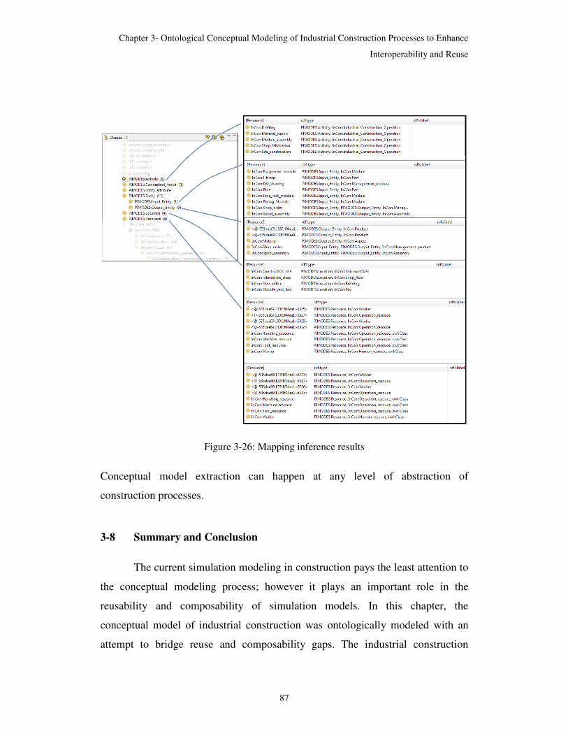
Chapter 3- Ontological Conceptual Modeling of Industrial Construction Processes to Enhance
Interoperability and Reuse
87
Figure 3-26: Mapping inference results
Conceptual model extraction can happen at any level of abstraction of
construction processes.
3-8 Summary and Conclusion
The current simulation modeling in construction pays the least attention to
the conceptual modeling process; however it plays an important role in the
reusability and composability of simulation models. In this chapter, the
conceptual model of industrial construction was ontologically modeled with an
attempt to bridge reuse and composability gaps. The industrial construction
Chapter 3- Ontological Conceptual Modeling of Industrial Construction Processes to Enhance
Interoperability and Reuse
88
ontology has a modular structure based on the process-modeling ontology. Taking
this approach for developing InCon-Onto has been particularly effective in
dealing with the interoperability challenges of construction simulation models.
Through the mapping process, an ontological framework of all the involved
simulation components is built and interoperability between the components is
facilitated. Instead of using existing tools, SPARQL, which is a query language,
has been used to formulize the articulation of mapping rules. The inference of
mapping rules results in sharing the knowledge content of the industrial
construction ontology with simulation application ontology, and carries the
conceptual model forward to the implementation phase. In the coming chapter, we
investigate reusability challenges through the development process, especially for
distributed simulation.
3-9 References
Doan, A., Madhavan, J., Domingos,P. and Halevy, A. (2001) “Learning to map
between ontologies on the semantic web”. In Proceedings of the 11th
International World Wide Web Conference, Hawaii, USA, 303-319.
El Diraby, T., Fies, B., and Lima, C. (2003). "An ontology for construction
knowledge management." Canadian Society for Civil Engineering - 31st
Annual Conference: 2003 Building our Civilization, Canadian Society for
Civil Engineering, 1949-1956.
El-Diraby, T. E., and Kashif, K. F. (2005). "Distributed ontology architecture for
knowledge management in highway construction" Journal of Construction
Engineering and Management, 131(5), 591-603.
El-Diraby, T. E., and Wang, B. (2005). “E-society portal: integrating urban
highway construction projects into the knowledge city." Journal of
Construction Engineering and Management, 131(11), 1196-1211.
El-Diraby, T. E., and Zhang, J. (2006). "A semantic framework to support
corporate memory management in building construction." Automation in
Construction, 15, 504-521.
El-Diraby, T. E., and Briceno, F. (2005). "Taxonomy for outside plant
construction in telecommunication infrastructure: supporting knowledge-
based virtual teaming." Journal of Infrastructure Systems, 11 (2), 110-121.

Chapter 3- Ontological Conceptual Modeling of Industrial Construction Processes to Enhance
Interoperability and Reuse
89
El-Gohary,N. 2008. “Semantic Process Modeling and Integration for
collaborative and Infrastructure Developments” Unpublished doctoral
dissertation, University of Toronto, Toronto, Canada
El-Gohary, N. M., and El-Diraby. T. E. 2010. “Domain ontology for processes in
infrastructure and construction” Journal of Construction Engineering and
Management 136(7), 730-744.
Fishwick, P. and J. Miller. 2004, “Ontologies for modeling and simulation: Issues
and approaches”. Proceedings of Winter Simulation Conference. 251-256.
Fürber, C., Hepp, M. (2010) “Using SPARQL and SPIN for Data Quality
Management on the Semantic Web”. Springer, Heidelberg, 35–46.
Gomez-Perez, A., Corcho,O. and Fernandez-Lopez,M. (2004) “Ontological
Engineering: With Examples from the Areas of Knowledge Management”, e-
Commerce and the Semantic Web, Advanced Information and Knowledge
Processing)
Gruber, T. R. (1995). "Toward principles for the design of ontologies used for
knowledge sharing" International Journal of Human Computer Studies, 43(5-
6), 907-928.
Gustavson, P., Chase T. 2007, “Building composable bridges between the
conceptual space and the implementation space”, Proceedings of the Winter
Simulation Conference, 804-814.
Hajjar, D., and AbouRizk, S. 1999. “Simphony: An environment for building
special purpose construction simulation tools.” 31th Winter Simulation
Conference, 998-1006.
Hajjar, D., and AbouRizk, S. 2002. “Unified modeling methodology for
construction simulation”, Journal of Construction Engineering and
Management, ASCE 128 (2) 174–185
Horridge M, Knublauch H, Rector A, Stevens R, Wroe C. 2004. “Practical
Guideto Building OWL Ontologies Using the Protégé-OWL Plugin and CO-
ODE ToolsEdition 1.0”. Manchester, UK: Univ. Manchester. 118 pp.
http://www.coode.org/resources/tutorials/ProtegeOWLTutorial.pdf, accessed
September 2007.
Kalfoglou, Y., Schorelmmer,M. (2003) “Ontology Mapping: The State of the
Art”, The Knowledge Engineering Review, Vol. 18:1, 1-31
Kawalek, P. (2004). "A quick tour of the process modelling world."
http://www.cs.man.ac.uk/ipR/CS637/quicktour.pdf
Chapter 3- Ontological Conceptual Modeling of Industrial Construction Processes to Enhance
Interoperability and Reuse
90
Knublauch, H. 2006, “TopBraid Composer and Protege-OWL”,
http://topquadrant.com/products/Protege_comparison.html (accessed October
2011)
Kotiadis, K., and Robinson, S. 2008, “Conceptual modelling: knowledge
acquisition and model abstraction”, S.J. Mason, R.R. Hill, L. Mönch, O.
Rose, T. Jefferson, J.W. Fowler, Editors , Proceedings of the Winter
Simulation Conference, 951-958.
Lacher, M. and Groh, G. (2001) “Facilitating the exchange of explicit knowledge
through ontology mappings”. In Proceedings of the 14th International
FLAIRS conference, 305-309, Key West, FL, USA.
Lacy, L. W. 2005a. PIMODES. 37th Winter Simulation Conference (Doctoral
Symposium).
Lacy, L. W. 2005b. PIMODES. Fourth International Semantic Web
Conference Doctoral Symposium. Galway, Ireland.
Lemaignan, S., Siadat, A., Dantan, J.-Y., Semenenko, A. (2006), “MASON: A
Proposal For An Ontology Of Manufacturing Domain Distributed Intelligent
Systems”. In Proceedings of International IEEE Workshop on Distributed
Intelligent Systems, Collective Intelligence and Its Applications, 195–200
Maedche, A. and Staab, S. (2000) “Semi-automatic engineering of ontologies
from texts”. In Proceedings of the 12th International Conference on Software
Engineering and Knowledge Engineering (SEKE 2000), Chicago, IL, USA,
231–239.
Makris, K., Bikakis, N., Gioldasis, N., Tsinaraki, C., and Christodoulakis, S.
(2009)” Towards a mediator based on OWL and SPARQL”. In Proceedings
of the 2nd World Summit on the Knowledge Society, 326-335
Martin, P., and Dacunto, A. 2003. “Design of a production system: An application
of integration product-process”. International Journal of Computer
Integrated Manufacturing, 16 7 (8): 509-16.
McGuinness , D.L. and Harmelen, F. 2003. “OWL Web Ontology Language
Overview,” www.w3.org/TR/owl-features
Moradi, F. (2007) “Component-based Simulation Model Development using
BOMs and Web Services”, in Proceedings of the first Asia Modelling
Symposium, AMS, 238-246.
Noy, N. F., and McGuinness, D. L. 2002 . Ontology development 101: A guide
to creating your first ontology, Knowledge System Laboratory, Stanford,
California.

Chapter 3- Ontological Conceptual Modeling of Industrial Construction Processes to Enhance
Interoperability and Reuse
91
Noy, N.F. and Musen, M. (2000) “PROMPT: Algorithm and Tool for Automated
Ontology Merging and Alignment”. In Proceedings of the 17th National
Conference on Artificial Intelligence (AAAI’00), Austin, TX, USA, 450-455
Obrst, L. (2006). “The Ontology Spectrum and Semantic Models. MITRE
Information Semantics Group”, Information Discovery & Understanding,
Center for Innovative Computing & Informatics
Prud’hommeaux, E., Seaborne, A.: SPARQL Query Language for RDF
(January2008), http://www.w3.org/TR/2008/REC-rdf-sparql-query-
20080115/
Rahm, A. and Bernstein, A. (2001) “A survey of approaches to automatic schema
matching”. The Very Large Databases Journal, 10(4):334–350
Renssen, A. van. 2003, “Gellish: An information representation language,
knowledge base, and ontology”. In Proceedings of the 3rd IEEE Conference
on Standardization and Innovation In Information Technology, 215-228.
Robinson, S. 2004. “Simulation: The Practice of Model Development and Use”.
Wiley, Chichester, UK.
Robinson, S. 2006. “Conceptual modeling for simulation: Issues and research
requirements”. Proceedings of the 2006 Winter Simulation Conference, 792-
800.
Shannon, R.E. 1975. “Systems Simulation: The Art and Science”, Prentice-Hall,
Englewood Cliffs, NJ.
Silver, G. A., Lacy, L. W. and Miller J. A. 2006. “Ontology based representations
of simulation models following the process interaction world view”. 38th
Winter Simulation Conference, 1168-1176
SISO. (2006). “BOM template specification”. SISO-STD-003-2006.
Storey, M.A., Mussen, M., Silva, J., Best, C., Ernst, N., Fergerson, , R., and Noy,
N. 2001. Jambalaya: Interactive visualization to enhance ontology authoring
and knowledge acquisition in Protégé. In Proceedings of Workshop on
Interactive Tools for Knowledge Capture, K-CAP-2001, Victoria, BC,
Canada, http://www.thechiselgroup.org/jambalaya.
TopBraid Composer(2010) ed: TopQuadrant, Inc
Tolk, A., and C. D. Turnitsa. 2007, ”Conceptual modeling of information
exchange requirements based on ontological means”. In Proceedings of the
Winter Simulation Conference, 1100-1107.

Chapter 3- Ontological Conceptual Modeling of Industrial Construction Processes to Enhance
Interoperability and Reuse
92
Tolk, D. A., and Muguira, J. A. (2003). "The levels of conceptual interoperability
model." In Proceedings of the 2003 Fall Simulation Interoperability
Workshop, number 03F-SIW-007, 14-19.
Uschold, M, and Gruniger, M., “Ontologies: Principles, methods and
applications”. Knowledge Engineering Review, 11(2):93–155, 1996.
Uschold, M., 1998, “Knowledge level modeling: concepts and terminology”. The
Knowledge Engineering Review, 13, 5–29.
Waterfeld,W., Weiten, M., Haase, P. (2008) “Ontology Management
Infrastructures”, Ontology Management Bd. 7. Springer, S. 59–87World
Wide Web Consortium, 2004, “Resource Description Framework (RDF)”
, http://www.w3.org/RDF/
World Wide Web Consortium, 2009, “Web Ontology Language (OWL)”,
http://www.w3.org/2001/sw/wiki/OWL
World Wide Web Consortium, 2008, Extensible Mark-up Language,
http://www.w3.org/TR/REC-xml/
World Wide Web Consortium, 2008, SPARQL Query Language for RDF,
http://www.w3.org/2001/sw/wiki/SPARQL
Zeigler, B.P. 1976. Theory of Modeling and Simulation. Wiley, New York

93
Chapter 4
Enhancing Reusability in HLA-based Distributed
Simulation Modeling of Industrial Construction
Processes
4-1 Introduction
The Construction Synthetic Environment (COSYE), which is a High Level Architecture
(HLA)-based distributed simulation environment, has been developed by AbouRizk (AbouRizk
et al. 2006). COSYE has already been utilized to model various large-scale construction and
industrial construction projects. In the second chapter, two examples of distributed simulation
models were presented. The models were integrated from independently developed components
by different simulation developers. However reuse, composability, and interoperability of these
simulation components are stated as HLA goals; still, it is difficult to fulfil these goals in
implementation (Radeski et al. 2002). The necessary requirement for reaching reusability and
interoperability is that unambiguous and structured formalization of information must be shared
and exchanged between distributed simulation modeling components (Tolk and Turnitsa 2007).
Ontological means have been taken in this research to link and drive information between
heterogeneous knowledge sources and illustrate how knowledge integration leads to increased
reusability and interoperability in distributed simulation modeling.

Chapter 4- An Ontology-Driven Framework to Facilitate Reusability of Distributed Simulation Modeling
of Industrial Construction Processes
94
4-2 Distributed Simulation Modeling Challenges
As was mentioned before, the key motivation for using distributed simulation modeling
in construction management is the decomposition of large-scale construction models into smaller
and more manageable components called federates, so that the development efforts are
distributed between different development groups. Once the federates have been developed
independently, they should be assembled together in order to build the entire model. This cannot
happen without consensus between all the involved collaborator parties about the knowledge that
they are sharing. All the parties have to take a harmonized approach towards all core aspects of
simulation modeling. Having a common understanding about the simulation modeling problem,
simulation modeling world view, and simulation modeling environment is the first step towards
successfully developing a distributed simulation modeling.
The approach taken in this research is based on ontological modeling of all different
aspects involved in a distributed simulation modeling. The approach uses semantic web
technologies to automate sharing and reusing knowledge within these different ontologies to
overcome current challenges facing the construction industry as it develops distributed
simulation models.
In the following section some of the challenges related to modeling construction
processes in a distributed simulation modeling environment based on HLA are investigated more
specifically. Subsequently the ontological modeling framework, including all the involved
components, is elaborately discussed. There is also a description of two specific cases that use
the ontological approach.

Chapter 4- An Ontology-Driven Framework to Facilitate Reusability of Distributed Simulation Modeling
of Industrial Construction Processes
95
4-2.1 Reuse and interoperability challenges within distributed simulation modeling
For the distributed simulation modeling components (federates) to be able to
communicate with each other, they should comply with a common representation for the
exchangeable information through shared federation object model (FOM) object classes and
interactions (IEEE 2000. Std 1516.2 2000). Developing an FOM, which all the collaborates
agrees on, takes lots of time and effort. On the other hand, communication dependency on FOM
highly restricts the federates’ reusability as any changes in FOM lead to lots of code updates and
modifications in the corresponding federates (Rathnam and Paredis 2004). That is why the
Federation Development and Execution Process (FEDEP) (Defense Modeling and Simulation
Office 1999) recommends reusing existing FOMs. In order to develop FOMs which facilitate
reusability, the industry should take a common approach towards FOM development. In this
chapter, ontologies provide the agreed-upon common and shared understanding of the domain
and simulation knowledge.
Another issue which is to be addressed by using ontolgies is the reusability spectrum in
the distributed simulation modeling environments. Reusability within HLA is focused on reusing
federates. The federates are treated as atomic simulation components, and reusing even a portion
of the code within them is almost impossible. The narrow reusability scope within distributed
simulation modeling often makes the development process complex and effort intensive
(Radeski et al. 2002). The steep learning curve and complexity associated with HLA rules and
standards are a part of development complexities. Developing simulation federates from reusable
elements, such as what exists in stand-alone construction simulation modeling environments,
reduces development efforts and therefore speeds up the development process of simulation
models (AbouRizk and Mohamed 2000). In this chapter, in order to apply an element-based
approach for distributed simulation modeling of construction operations, breakdown of elements
and their characteristics are identified and developed serving process interaction concepts while
providing HLA communication services.

Chapter 4- An Ontology-Driven Framework to Facilitate Reusability of Distributed Simulation Modeling
of Industrial Construction Processes
96
4-3 Ontology-Driven Framework for Construction Simulation Modeling
4-3.1 Overview on ontological framework
In chapter 2 we presented the ontological framework of the involved simulation
components modeled and linked together. As was discussed before, the framework (Figure 4-1)
consists of two parts: industrial domain and simulation domain. Industrial construction processes
are modeled through process-modeling concepts within Industrial Construction Ontology
(InCon-Onto).
Figure 4-1: The ontological framework of construction simulation components

Chapter 4- An Ontology-Driven Framework to Facilitate Reusability of Distributed Simulation Modeling
of Industrial Construction Processes
97
The simulation domain itself has two parts: simulation world view and simulation
application. The modeling representation follows a process-oriented world view ontology
presented in POMIDES ontology developed by Lacy (2005). The simulation application is an
element-based presentation of distributed simulation modeling consisting of federates, focusing
on modeling the dynamics of processes. FOM, representing products and resources dealing with
processes, is also captured within ontologies. All ontological components were explained in
Chapter 2. The only component which is discussed further is the simulation application
component.
4-3.2 Simulation application ontologies
The ontology of the simulation interface formalizes the software interface with which the
simulation developer is dealing. In this research, as was stated before, the distributed simulation
model is developed in an element-based environment of a Special Purpose Simulation (SPS) tool
called Simphony. FOM provides the federate’s communications means with other federates,
which might be developed using different applications. Therefore the simulation application
ontology has two components: Simphony, which was explained previously, and FOM.
FOM Ontology: This specifies the major components of FOM, which are composed of
object classes, attributes, interactions, and parameters which are going to be shared and
exchanged within federates. The entire framework is encoded using OWL/RDF semantic
languages as was explained previously.

Chapter 4- An Ontology-Driven Framework to Facilitate Reusability of Distributed Simulation Modeling
of Industrial Construction Processes
98
4-4 Ontology-Driven Applications
4-4.1 Role of industrial construction ontology in modeling industrial construction
processes at multiple levels of abstraction
Modeling industrial construction processes in the COSYE environment allows for the
overall system to decompose into multiple components, which means that models are developed
at different levels of abstraction. At low resolution of a large-scale model, all parties involved in
developing the simulation model have to reach consensus so that the simulation components will
be able to communicate with each other. At lower resolution, few objects or processes can be
aggregated into one object. Successful implementation of models at different levels of
abstraction requires a decomposition strategy which can keep up with consistency of information
at different levels for later integration of simulation components (Benjamin et al. 1998, 2006).
Ontology-driven modeling of large industrial processes provides a reference for decomposing the
process while preserving consistency and connection between the components. The breakdown
of processes in InCon-Onto follows the real-world implementation of the processes. Each main
component is managed separately from others and has its own domain expertise and final users.
The ontological-driven approach is fast yet reliable. Within this approach, the level of
abstraction is chosen and then all the related resources and products of those processes can be
queried from the domain ontology. The extraction queries are imposed upon InCon-Onto through
process interaction ontology (PIMODES; Lacy, 2006) which consists of components of the
industrial construction ontological framework. As an example, querying the InCon-Onto at high
level industrial construction can provide the breakdown of industrial construction processes as
different federates (Figure 4-2) (The query is almost similar to Figure 2-31). As shown in figure
the industrial construction federates can be the following: drafting, material supply, module
assembly, shop fabrication, and site construction. All involved objects at this level are shown as
products or resources forming the federation object model of the federation. It should be noted
that domain ontologies are helpful in developing domain-dependent federates. Domain-

Chapter 4- An Ontology-Driven Framework to Facilitate Reusability of Distributed Simulation Modeling
of Industrial Construction Processes
99
independent federates, such as the calendar federate, weather federate, site condition, and
resource allocation federate, are commonly used in different construction domain federations.
The federates and federation model objects should be considered and included separately.
In order to step into lower levels of abstraction, we can query the lower layers of
industrial construction processes as shown in the following figure (Figure 4-2).
Figure 4-2: The ontological driven simulation components
Ontological-driven modeling guarantees that model behaviour will be consistent at different
levels of abstraction. But the benefits of the ontological modeling framework are not limited to

Chapter 4- An Ontology-Driven Framework to Facilitate Reusability of Distributed Simulation Modeling
of Industrial Construction Processes
100
this. With the help of ontologies, maintaining object consistency is automatic. The following
section discusses extracting the federation’s FOM from InCon-Onto.
4-4.2 FOM extraction from industrial construction ontology
FOM specifies a common representation for all the shared objects and interactions
between all the federates.
Object Model Template (OMT) is the meta-data and contains the structure of objects,
attributes, interactions, and parameters.
As discussed in the previous section, the simulation platform contains multiple
heterogeneous ontologies but they have to become linked together to build an industrial
construction simulation model. In order to build the connection between modeling
representation components with real-world representation, components’ semantic roles should be
considered (Benjamin et al. 2005). Industrial construction processes are the dynamic core of the
model. The federation’s object model mainly represents the products and resources whose status
is shared and updated by interested federates. InCon-Onto components are linked to their
counterparts in FOM ontology (Table 4-1).
Table 4-1: Linking InCon-Onto concepts to FOM components
InCon-Onto Concept FOM Corresponding
Concept Product Object Class
Resource Object Class
Product Data-type
property
Attribute
Resource Data-type
property
Attribute

Chapter 4- An Ontology-Driven Framework to Facilitate Reusability of Distributed Simulation Modeling
of Industrial Construction Processes
101
Mapping the two ontologies builds a bridge for information transformation from InCon-
Onto to the FOM. The transformation mechanism between the two ontologies is built using
SPARQL (SPARQL Protocol and RDF Query Language) queries (Scharffe and Fensel 2008).
The main objective is instance transformation for different FOM components, so that a
set of instances referring to the source ontology (in this case, InCon-Onto) is transferred into
instances belonging to the target ontology (in this case, ontology). In the following example,
product instances are transformed to object class instances within the following SPARQL
construct statement:
CONSTRUCT
{
? X rdf:type FOM:object Class.
WHERE
?X rdf:type InCon-Onto:Product.
}
Adding other SPARQL constructs such as FILTER and UNION allows for more
sophisticated queries for information transformation. For instance, we could just include
products which belong to a certain process, i.e., only module assembly process products. The
mapping outcome is an enriched FOM ontology with related instances from InCon-Onto. As
FOM is originally an XML document, the final step would be mapping the FOM Ontology to the
FOM XML schema. Figure 4-3 summarizes the entire object instances transformation process.

Chapter 4- An Ontology-Driven Framework to Facilitate Reusability of Distributed Simulation Modeling
of Industrial Construction Processes
102
Figure 4-3: Object instances transformation from InCon-Onto to FOM
The discussed method is able to extract all the objects involved in the FOM in the form of
queries’ results. In order to have the final FOM, the queries’ results should be simply put
together. But still, that does not mean that the outcome can be used as FOM, as it has no manual
interventions, especially regarding data-types. The current adapted OMT in COSYE has a very
complicated structure which makes it a challenge to apply it to the FOM ontology. Another part
of the FOM which is not covered through this method is that of interactions and parameters.
Using interactions has not been popular in the related FOM of different construction federations
developed at the University of Alberta Construction Engineering and Management (CEM) group.
Table 4-2 shows the statistics of different FOM components in four different federations.
The result of ontology extraction includes all the involved objects and their related
attributes, but does not cover the interaction and parameters involved in the FOM.

Chapter 4- An Ontology-Driven Framework to Facilitate Reusability of Distributed Simulation Modeling
of Industrial Construction Processes
103
Table 4-2: The statistics of different FOM components in different federations
Fed
eration
Ob
ject/Attrib
ute (1
st level)
Ob
ject/Attrib
ute (2
nd lev
el)
Ob
ject/Attrib
ute (3
rd level)
Ob
ject/Attrib
ute (4
th level)
Interactio
n/ p
arameter
Industrial construction 1 4/34 4/32 3/8 4/9 4/9
Industrial construction 2 5/34 0/0 0/0 0/0 1/1
Tunnelling 12/34 17/127 15/69 0/0 1/3
Structural steel 5/44 0/0 0/0 0/0 0/0
4-4.3 Developing ontology-based process interaction elements
Regardless of the simulation environment, when the world view is the same, the same
concepts are used to represent the models. The same applies to the distributed environment;
however, process-interaction code implementations are coupled with communication service
constructs, so that they can satisfy distributed and parallel simulation modeling requirements.
These federate developments are ad-hoc implementations without a standard framework for
facilitating packaging and deployment for reusable piece parts. In the current study we have tried
to come up with packaging these piece parts according to the available process interaction
ontology introduced before. Table 4-3 shows the formal concepts of process-interaction from
PIMODES and the equivalent concepts used in stand-alone simulation software (Simphony) and
the construction distributed simulation modeling environment (COSYE).
Table 4-3: Modeling environment process interaction concepts mapping

Chapter 4- An Ontology-Driven Framework to Facilitate Reusability of Distributed Simulation Modeling
of Industrial Construction Processes
104
Org
an
iza
tio
na
l
Co
nce
pt
PO
MID
ES
(D
ES
On
tolo
gy
)
Sim
ph
on
y
CO
SY
E (
new
ly
def
ined
ele
men
ts)
Act
ivit
y C
on
cep
ts
Creation Activity New Entity Register
Assignment Activity Set Attribute Update
Resource Interaction
Activity (Seize/Release)
Capture/Release Capture/Release
Delay Activity Task Delay
Branch Activity
Probability Branch
Filter
Conditional Branch
Queue Activity Waiting file Waiting file
Disposition Activity Delete Entity Delete
Pro
cess
Co
nce
pts
Entity Type - -
Entity Entity Proxy Entity
Location Resource Resource
Variable Variable Variable
Resource Resource Resource
Entity Attribute Entity Attribute Entity Attribute
When a federate presents a model through the process-interaction world view, the model
is composed of process interaction concepts coupled with HLA communication and sharing

Chapter 4- An Ontology-Driven Framework to Facilitate Reusability of Distributed Simulation Modeling
of Industrial Construction Processes
105
requirements, although not necessarily in the organized way presented in Table 4-3. For instance,
for capturing or releasing a resource, the simulation federate not only needs to employ simulation
services in order to capture the resource, but before that it should request the resource object
instance ownership and then go through the simulation process and at the end divest the object
instance ownership so that the object instance can be seized by other components. Reviewing
different simulation federates helps to find the set of modeling constructs corresponding to each
process interaction concept and find out and document their common description, properties,
conditions, and exceptions. This experiment was performed on developed federations. The
inclusive code was packaged within elements to be used in federates developed in a visual
environment such as Simphony. The following are the set of COSYE elements which have been
programmed to serve, at the same time, the process interaction simulation elements and
communication requirements of distributed simulation.
4-4.3.1 Description of COSYE-compliant elements
Register: The “Register” element notifies Run Time Infrastructure (RTI) about the “quantity
number,” which is the number of object instances (proxy entities) that has been created, and
passes it along to the destination element. For the “initial quantity” of entities, the instances of
the object class are registered before simulation starts.
Update: The “Update” element is a combination of the update attribute event and delay function;
it notifies RTI that the attribute value of an associated object instance has been updated after a
delay time.
Reflect: The “Reflect” element is used when other simulation federates need to know the
attribute value of an object instance. When the attribute that the federate has subscribed to
changes, the RTI sends a notification to the interested federates.

Chapter 4- An Ontology-Driven Framework to Facilitate Reusability of Distributed Simulation Modeling
of Industrial Construction Processes
106
Filter: After receiving the attribute value of an object instance via the “Reflect” element, the
modeller is usually interested in a particular attribute value, and the elements with different
attribute values will be filtered.
4-5 Distributed Simulation Model of Industrial Construction Processes
The entire process of industrial construction has been modeled as a large-scale and
distributed simulation model (AbouRizk et al. 2010). The present model is an enhancement of
previous development, with the same model decomposition (Figure 4-4) accompanied by the
extracted FOM XML document from FOM Ontology, containing the object classes and attributes
shared between simulation federates. The major difference in the federation happened with the
spool fabrication federate, which was replaced with the newly developed element-based federate
in a visual environment. The new model is built from COSYE-aware elements, customized for
the shop fabrication domain. The fabrication shop federate’s simulation behaviour is explained in
the following section.
Figure 4-4: Industrial construction federation (AbouRizk et al. 2010)
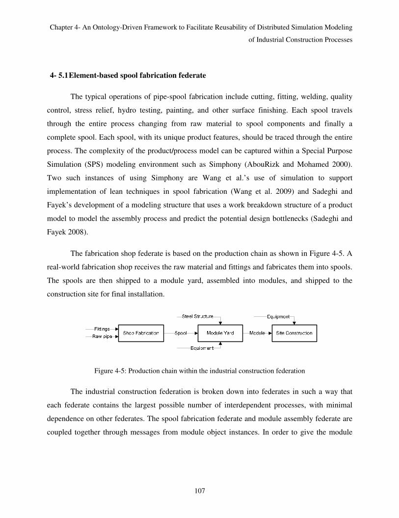
Chapter 4- An Ontology-Driven Framework to Facilitate Reusability of Distributed Simulation Modeling
of Industrial Construction Processes
107
4- 5.1 Element-based spool fabrication federate
The typical operations of pipe-spool fabrication include cutting, fitting, welding, quality
control, stress relief, hydro testing, painting, and other surface finishing. Each spool travels
through the entire process changing from raw material to spool components and finally a
complete spool. Each spool, with its unique product features, should be traced through the entire
process. The complexity of the product/process model can be captured within a Special Purpose
Simulation (SPS) modeling environment such as Simphony (AbouRizk and Mohamed 2000).
Two such instances of using Simphony are Wang et al.’s use of simulation to support
implementation of lean techniques in spool fabrication (Wang et al. 2009) and Sadeghi and
Fayek’s development of a modeling structure that uses a work breakdown structure of a product
model to model the assembly process and predict the potential design bottlenecks (Sadeghi and
Fayek 2008).
The fabrication shop federate is based on the production chain as shown in Figure 4-5. A
real-world fabrication shop receives the raw material and fittings and fabricates them into spools.
The spools are then shipped to a module yard, assembled into modules, and shipped to the
construction site for final installation.
Figure 4-5: Production chain within the industrial construction federation
The industrial construction federation is broken down into federates in such a way that
each federate contains the largest possible number of interdependent processes, with minimal
dependence on other federates. The spool fabrication federate and module assembly federate are
coupled together through messages from module object instances. In order to give the module

Chapter 4- An Ontology-Driven Framework to Facilitate Reusability of Distributed Simulation Modeling
of Industrial Construction Processes
108
instances, the ability to flow as a regular simulation entity, and also an object instance, a module
carries two identities at the same time: (1) it is a proxy entity that can be transferred to other
traditional simulation elements and (2) it is an object instance that can be communicated between
different federates. When all the spools belonging to a particular module have been fabricated,
they are shipped to the module yard. When other necessary resources are available, module
assembly can start. What happens within and between federates is shown in Figure 4-6.
Figure 4-6: Unified Modeling Language (UML) description federates’ interaction
The COSYE modeling elements described before feature the most common functions
needed to develop a distributed-simulation model within the process-interaction world view.
These elements are customized to better serve the simulation of the industrial construction
domain by adding additional behaviours. In the following, the fabrication process elements are
explained and a spool fabrication federate is developed utilizing these elements. The federate
models a scenario of pipe spool fabrication processes (Figure 4-7). The elements’ detailed
description and their code is attached in Appendix III.

Chapter 4- An Ontology-Driven Framework to Facilitate Reusability of Distributed Simulation Modeling
of Industrial Construction Processes
109
Register Modules by Interval: The Register element registers a quantity number of module
entities and passes them along to the destination element. (Module entities are module object
instances; the module object class and its attributes are shared between the fabrication shop
federate and module assembly federate through the industrial construction FOM.) The first
module object instance is registered at time zero, and the subsequent object instance will be
registered at a specified time interval.
Update Module Attributes: Through the Update element, the attribute values of module object
instances are initialized. In this element, the initial attribute values are assigned to each module
object instance. Attributes are as follows:
- Total number of spools (the attribute value is a sample of a triangular distribution).
- Total number of fabricated spools (equal to zero at the start of the simulation process).
- State of module instance (fabrication shop at the start, then module yard followed by site
construction).
- Component ready time (the time at which all the spools of a module instance have been
fabricated and the module is ready to be assembled).
- Modules assembly priority is used for the fabrication process. All of these attributes can
be communicated to other federates that require the information.
Figure 4-7: Fabrication shop federate developed in Simphony environment using COSYE elements

Chapter 4- An Ontology-Driven Framework to Facilitate Reusability of Distributed Simulation Modeling
of Industrial Construction Processes
110
Reflect: Due to changes in module assembly or field construction, the order of module
installation and subsequently the priority of assembling a module might change. In these cases
the initial priority is updated in the module assembly federate, which will be updated in the
fabrication federate through the Reflect element.
Create Spool for Module, Create Spool Components: This element receives the module entity,
and for each module creates a corresponding number of spools, including their physical
configurations and attributes.
Dispatch: This element sends the entities to the appropriate destination element, based on the
entity’s properties.
Fabrication Station: This represents any type of work station that material or spool components
go through during the fabrication process. The processes are cutting, roll and position fitting, roll
and fixed welding, and quality control and hydro test. Entities are sent to different stations based
on their properties, even when the process is the same. For instance, spool components with a
different diameter size (small, intermediate, large) will each go to a different fitting station.
Handling: This element models the handling process in fabrication, either between work stations
and lie-down areas or out of the fabrication shop. The element supports two types of handling:
manual or crane.
Assembler: This element keeps track of spool components; it collects from one spool all the
components that have gone through roll fitting and welding and sends the spool to the final stage
of assembly.
Modules Assembler: The function of this element is similar to the assembler element, but
operates for spools that belong to the same module. When all the spools of one module are
available, this element updates and sends the module attributes to the RTI for the module
assembly federate to use.

Chapter 4- An Ontology-Driven Framework to Facilitate Reusability of Distributed Simulation Modeling
of Industrial Construction Processes
111
From composition of instances of these elements, spool fabrication federate is built. The
federate serves as one of the simulation federates of the entire industrial construction federation.
4-6 Discussion on Component-based Industrial Construction Distributed model
Assembling simulation models from reusable elements brings more flexibility, ease and,
more importantly, reusability to developing large-scale distributed simulation models. Here are
more specific outcomes of this approach:
Component-based simulation modeling has generally known advantages. Such as:
• It allows for building a complex simulation model from aggregating reusable elements.
• It makes understanding a model easier, even for non-modellers
• It facilitates verification and validation of the model through element unit testing
Increased reusability scope in the distributed simulation modeling environments: At the
simulation level, traditionally each federate is regarded as an atomic object and its reuse within
the federates is not taken into consideration. Within our approach federates are built from
reusable components which speeds up their development and makes it more structured.
4-7 Summary and Conclusion
This chapter described an ontology-driven framework for developing distributed
simulation modeling of construction processes. The use of an ontological modeling framework
has been shown through mapping different ontological components with process modeling
concepts, which provide effective yet simple rules for sharing information between simulation
ontological components. This technique is used to extract the needed information from the
construction process ontology into simulation representation components. Another use of
ontologies is discussed through element identification for an element-based environment within a

Chapter 4- An Ontology-Driven Framework to Facilitate Reusability of Distributed Simulation Modeling
of Industrial Construction Processes
112
distributed environment. In both of these cases, reusing existing information and modeling
elements within the distributed simulation modeling environment leads to enhanced reusability,
which results in a more efficient development process and provides a more sustainable
mechanism for developing distributed construction simulation models.
4-8 References
AbouRizk, S., 2006. Collaborative Simulation Framework for Multi-user Support in
Construction. Discovery Grant Proposal, Edmonton, Alberta, CA.
Abourizk, S., and Mohamed, Y. 2002. Optimal construction project planning. Winter Simulation
Conferonce.
AbouRizk, S., Mohamed, Y., Taghaddos, H., Saba, F., and Hague., S. 2010. Developing
complex distributed simulation for industrial plant construction using high level architecture.
42th Winter Simulation Conference.
AbouRizk, S., and Mohamed, Y. 2000. "Simphony: An integrated environment for construction
simulation", 32th Winter Simulation Conference. 1907 - 1914
Baqai, A., Siadat, A., Dantan, J. Y. and Martin, P. 2008. "Use of a manufacturing ontology and
function-behaviour-structure approach for the design of a reconfigurable machine tool",
International Journal of Product Lifecycle Management 3 (2): 132-50.
Barrie, D.S. and Paulson, B.C. 1992. "Professional Construction Management, Including
C.M., Design Construct, and General Contracting", 3rd ed. New York: McGraw-Hill,
Inc.
Benjamin, P., Akella, K. V., Malek, K., and Fernandes, R. 2005."An ontology-driven
framework for process-oriented applications". 37th conference on Winter simulation, 2355-
2363.
Defense Modeling and Simulation Office (DMSO). 1999. "High level architecture: Federation
development and execution process (FEDEP) model".
El-Gohary, N. M., and El-Diraby. T. E. 2010. "Domain ontology for processes in infrastructure
and construction". Journal of Construction Engineering and Management, 269-283

Chapter 4- An Ontology-Driven Framework to Facilitate Reusability of Distributed Simulation Modeling
of Industrial Construction Processes
113
Gruber, Thomas R. 1995. "Toward principles for the design of ontologies used for knowledge
sharing". International journal of human computer studies, 43 (5-6) (December): 907-928.
Hajjar, D., and AbouRizk, S. 1999. "Simphony: An environment for building special purpose
construction simulation tools". 31th Winter Simulation Conference, 998-1006.
Halpin, D. W., Jen, H. and Kim., J. 2003. "A construction process simulation web service". 35th
Winter Simulation Conference, 1503-1509.
IEEE 2000. Std 1516.2. 2000. Standard for modeling and simulation (M&S) high level
architecture (HLA) - object model template (OMT) specification.
Kelin, U., Schulze, T. and Strassburger, S. 1998. "Traffic simulation based on the high level
architecture". 30th Winter Simulation Conference, 1095-1104.
Kuhl, F., Weatherly, R. and Dahman., J. 1999. "Creating computer simulation systems: An
introduction to the high level architecture", Englewood Cliffs, NJ: Prentice Hall.
Lacy, L. W. 2005a. PIMODES. 37th Winter Simulation Conference (Doctoral Symposium).
Lacy, L. W. 2005b. "PIMODES". Fourth International Semantic Web Conference Doctoral
Symposium. Galway, Ireland.
Lee, J., Lee, M., and Chi, S., 2003. "DEVS/HLA-based modeling and simulation for intelligent
transportation systems". Simulation 79 (8) (August 01): 423-39.
Martin, P., and Dacunto, A. 2003. "Design of a production system: An application of integration
product-process". International Journal of Computer Integrated Manufacturing, 16 7 (8):
509-16.
Mohamed, Y., Borrego, D., Francisco,L., Al-Hussein,M., Abourizk,S. and Hermann, U. 2007.
"Simulation-based scheduling of module assembly yards: Case study". Engineering,
Construction and Architectural Management 14 (3): 293-311.
Protégé (2006), "Protege an free open source ontology editor and knowledgebase framework",
Stanford University, Standord University School of Medicine, Stanford Medical Informatics,
California, USA Available at: protege.stanford.edu.
Radeski, A., Parr, S., Keith-Magee, R., and Wharington, J., 2002. "Component-based
development extensions to HLA". Spring Simulation Interoperability Workshop, Paper ID
02S-SIW-046, March 2002.

Chapter 4- An Ontology-Driven Framework to Facilitate Reusability of Distributed Simulation Modeling
of Industrial Construction Processes
114
Rathnam, T., and Paredis, C. J. J. 2004. "Developing federation object models using ontologies".
preceeding of the 2004 Winter Simulation Conference, 36th Winter Simulation Conference,
1054–1052.
Sadeghi, N., and Robinson Fayek, A. 2008. "A framework for simulating industrial construction
processes". 40th Winter Simulation Conference, Miami, Florida, 2396-2401.
Scharffe, F., and Fensel, D. 2008."Correspondence patterns for ontology alignment". Knowledge
Engineering: Practice and Patterns: 83-92.
Silver, G. A., Lacy, L. W. and Miller J. A. 2006. "Ontology based representations of simulation
models following the process interaction world view". 38th Winter Simulation Conference,
55-63.
Tolk, A., and Turnitsa, C. D. 2007. "Conceptual modeling of information exchange requirements
based on ontological means". 39th Winter Simulation Conference, 1100-1107.
Wang, P., Mohamed, Y. and AbouRizk, S. 2005. "Production-based large scale simulation
modeling for construction projects". 33rd CSCE Annual Conference.
Wang, P., Mohamed, Y. and AbouRizk, S., and Rawa., A. R. T. 2009. Flow production of pipe
spool fabrication: Simulation to support implementation of lean technique. Journal of
Construction Engineering & Management, 135 (10) (10): 1027-1038.
Benjamin, P., Erraguntla, J . Delen, D. and Mayer, R., 1998, "Simulation modeling at multiple
levels of abstraction". In Proceedings of the 1998 Winter Simulation Conference. 391 - 398
Benjamin, P., M. Patki, and R. Mayer. 2006. "Using ontologies for simulation modeling". In
Proceedings of the Winter Simulation Conference, 1151 - 1159..

115
Chapter 5
A Semantic Approach to Representation, Sharing
and Discovery of Construction Simulation
Models
1 Parts of Chapter 5 has been submitted to Construction 2012 Research Congress
5-1 Introduction
Simulation modeling is an effective tool for analyzing construction operations and
supporting the decision-making process (Halpin et al. 2003). Simulation model development
consumes lots of time and resources. The models are the result of extensive knowledge
acquisition in different domains: knowledge of construction, and simulation modeling techniques
and tools. When the model is used for its initial intention, its reuse is not straightforward, mostly
because the process of finding the appropriate modelling components for reuse has not yet been
addressed (Aronson and Bose 1999, Chreyh and Wainer 2009). This problem can be traced back
to the accessibility and availability of models and their content (e.g., simulation components and
their behaviour) for simulation, which so far has not been addressed, especially in the
construction domain.

Chapter 5- A Semantic Approach to Representation, Sharing and Discovery of Construction Simulation Models
116
With internet technology advances, simulation models can be shared in repositories and
distributed over the web, while with efficient web discovery services, the knowledge residing
within them can be extracted. This advancement has not yet been introduced to the construction
industry. In order to share construction simulation models and facilitate meaningful discovery on
the Web, simulation models including model features and model behaviour must be represented
in an appropriate format, one that the semantic web can process. Sharing and discovering
simulation models is richer when the models are properly linked to other useful and relevant
sources of information (e.g., maps, different documents and spread sheets, drawings, images,
video and audio files).
The innovative architecture presented in this chapter blends semantic web technologies
and construction simulation models presented in machine interpretable metadata for storing,
sharing, and discovering construction simulation models and properly linking them to their
related information sources. This environment utilizes semantic web technology which has been
used for resolving similar challenges such as reusability, composability, and interoperability of
resources within the WWW. The goal is to adapt such techniques into the construction
simulation world.
The next section presents a brief background about the use of semantic web and its use in
simulation. This is followed by our methodology to apply semantic web techniques and
technology in construction simulation modeling. Afterwards, the main research efforts are
presented, including a semantic representation of simulation models with the aim of easy
discovery and reuse of simulation model components. We also introduce a semantic web-based
environment which supports storage of simulation models and knowledge extraction and
discovery. Then the prototype is presented and, finally, the summary and future works are
discussed.

Chapter 5- A Semantic Approach to Representation, Sharing and Discovery of Construction Simulation Models
117
5-2 Semantic Web
The semantic web is revolutionizing the World Wide Web. It describes methods and
technologies to allow machines to understand the meaning or "semantics" of information on the
WWW. The traditional web is just about displaying information. It lacks the semantics
underpinning for meaningful sharing and discovery of resources. Data, information, and
knowledge-sharing are more prolific on the semantic web because they can be linked to relevant
sources across the web.
The semantic web is a network of data described and linked in ways to establish content
or semantics, which enables machines to be able to interpret the data and act upon the web
content. This enables more efficient searching, sharing, and information combinations.
The semantic web consists of different types of statements that allow for the formation of
rich expressions, and also for simplified integration and sharing, enabling inference, and
extraction of meaningful information. The semantic web content is made up of resources which
are linked through relationships.
The languages and technologies that comprise the semantic web are shown in semantic
web stack (Figure 5-1). The bottom layer contains foundation technologies of the hypertext web,
which are also the basis for the semantic web; Unicode, Uniform Resource Identifier (URI), and
XML are technologies used for character encoding, resource indexing, and syntax for data
serialization. RDF, RDF Schema (RDF-S), OWL, SPARQL, and Semantic Web Rule Language
(SWRL) are standardized technologies used for enabling semantic web applications, including
functions for description, rule setting, and querying.

Chapter 5- A Semantic Approach to Representation, Sharing and Discovery of Construction Simulation Models
118
Figure 5-1: Semantic Web Stack (adapted from w3.org)
5-2.1 Semantic web languages: XML
Unlike standard text files or HTML web pages, eXtensible Markup Language (XML) is
not only about a form of display, it also contains content representation encoding.
XML is a simple but flexible mark-up language. An XML document contains mark-up
and content, where mark-up is the means to add structure and syntax to the data by allowing
users to create their own tags. Within XML, elements are data containers which may contain
nested elements. Furthermore, elements can include an attribute, which is an explanation about
the element content.
The fact that the user is able to create her own data structure makes the language flexible,
but the structure is still not machine interpretable and is easily prone to errors. That is solved by
another document called schema, which is the description of the XML structure within a set of
rules to which an XML document must conform in order to be considered valid according to that
schema.
The structured data through XML tags can be employed to exchange data across
information systems that may had been built upon different platforms.

Chapter 5- A Semantic Approach to Representation, Sharing and Discovery of Construction Simulation Models
119
5-2.2 Semantic web languages: RDF
XML is used for structuring information, while RDF is used for conceptually describing
or modeling the information. RDF (Resource Description Framework) accepted by World Wide
Web Consortium (W3C) to standardize information stored on the Web. RDF uses a labelled
graph data format for representing information on the Web.
The RDF statements, consisting of triples (subject, predicate, object), form graphs and the
nodes, represent either the subject, object, or predicate. Where the subject refers to the resource
and can be represented by a Uniform Resource Identifier (URI), the predicate refers to the
resource’s features or characteristics and expresses the relationship between the resource and the
object. Finally, the object is a resource or a string.
RDF-S is an extension to RDF to support the expression of structured information. It
provides an ontology representation language which has been widely used.
5-2.3 Semantic web languages: OWL
OWL builds upon RDF-S and provides greater expressivity in the description of concepts
and relationships. The OWL expressiveness allows different domain knowledge modeling, (i.e.,
ontologies). Ontologies provide formal methods for describing the concepts, categories, and
relationships within a domain (McGuinness and Harmelen 2004). OWL supports expressing
cardinalities, hierarchical properties, and capabilities of properties (e.g., transitive, symmetric). It
has three versions with different expressivity: OWL-Lite, OWL-DL and OWL-Full.
5-2.4 Semantic web languages: RDF Query Language (SPARQL)
SPARQL is a declarative language that the W3C recommends for extracting information
from RDF graphs using queries across diverse data sources.

Chapter 5- A Semantic Approach to Representation, Sharing and Discovery of Construction Simulation Models
120
SPARQL has four query forms: SELECT, CONSTRUCT, ASK, and DESCRIBE. These
query forms use pattern matching to form result sets or RDF graphs. SELECT returns matching
triples with the query. CONSTRUCT returns an RDF graph. ASK returns a Boolean indicating
whether a query pattern matches or not, and DESCRIBE returns an RDF graph that describes the
found resources. Result sets can also be serialized into either XML or RDF.
5-3 Related Work
The semantic web brings with it new ways of thinking about modeling and new methods
and tools (Taylor 2011). The following are some of the instances of use of semantic web
techniques and technologies in simulation and modeling.
Ontologies have been proposed to represent knowledge about simulation modeling
domains. The first simulation ontology is Discrete Event Model Ontology (DeMO) which is a
comprehensive Discrete Event Simulation (DES) ontology containing templates which capture
knowledge of different simulation world views such as activity-oriented, event-oriented, state-
oriented and process-oriented (Fishwick and Miller 2004). This ontology is a suitable resource
for obtaining a comprehensive understanding of DES.
The Process Interaction Modeling Ontology for Discrete Event Simulations (PIMODES)
is another simulation ontology by Lacy (2005b, 2005c), which is built specifically for the process
interaction world view, a popular paradigm for representing DES. PIMODES is heavily
influenced by popular software packages such as Arena, AnyLogic, and ProModel. This makes
it easy to connect PIMODES to software packages. PIMODES can be used for an ontology-
based representation of models which facilitates the interchange of simulation models between
different simulation packages. Sliver et. al (2007) suggested a technique to establish links
between domain ontologies and simulation ontologies and use these relationships to instantiate a
simulation model. Lozano et. al (2009) presented a semantic approach to simulation component
identification and discovery. They used Simulation Reference Mark-up Language (SRML)

Chapter 5- A Semantic Approach to Representation, Sharing and Discovery of Construction Simulation Models
121
documents to search through a simulation repository of Base Object Models (BOM). BOM is a
Simulation Interoperability Standards Organization (SISO) standard for conceptual modeling
documentation. It provides a formal way to capture and share conceptual simulation
documentation (Gustavson 1998). Moradi et al. have investigated ontological BOM discovery
and composition for building new models (Moradi et al. 2007). Fishwick recently proposed
hypermodeling, the general theory and practice of linking system models and their components
(2011).
One of few efforts in the construction domain towards using web services has been made
by Halpin et. al (2003). They have used web-based simulation modeling for simplified access to
a construction simulation modeling tool, providing different levels of interface for people at
different levels of simulation and domain knowledge. However, this work certainly does not seek
to take advantage of the semantic web.
Within this chapter, the goal is to borrow semantic web techniques and technology and
apply them to construction simulation modeling. Within this adaptation, a new representation is
given to simulation models through the use of semantic mark-up languages. Using query
capabilities of semantic mark-up languages, the knowledge and information within simulation
models can be retrieved and processed. Within the proposed representation, the simulation
models and their components can become connected to relevant and useful sources of data and
information on the web. The semantic web technology brings other advantages regarding
reusability, composability, and interoperability to construction simulation models, which are
discussed later in the chapter.
5-4 Adaptation of Semantic Web into Construction Simulation Modeling
Adapting semantic web techniques and technologies has significant effects on modeling,
discovery, composition, interoperability and reuse of simulation models. In order to be able to
apply these techniques to existing construction engineering simulation models developed in

Chapter 5- A Semantic Approach to Representation, Sharing and Discovery of Construction Simulation Models
122
conventional construction simulation modeling tools, some pre-work on models is needed, as
follows:
1- Model representation: Any storing, sharing, and discovery in the semantic web is highly
dependent on the model’s structure and encoding. As mentioned before, information
encoded within semantic mark-up languages such as XML, RDF, or OWL is semantic
web readable. The coming section explains how the XML text view of models developed
in Simphony (A special purpose simulation modeling tool) is used as the basis for the
semantic representation of simulation models of construction operations.
2- Model content: The acquired models need enhancement both in representation and
content. The XML text view of models contains a full description of the modeling
elements and their input and output properties, along with the relationships within the
elements. But it does not provide essential big picture information about the model. This
information is important for sharing and discovery purposes and is added to the model
through a separate section in the XML model description, the model “profile.”
3- Linking the relevant sources of data and information: An important aspect of the
semantic web is proper linking to relevant information. Simulation models are always
built based on vast amounts of knowledge coming from conceptual models and
documents containing input data. The sources are included in the repository through
linking them to the model. The linking is cited in the added “profile” section.
4- Outcomes of semantic web adaptation in construction simulation modeling encompass a
wide range of enhancement in reusability, composability, and interoperability. Tangible
examples of knowledge extraction through SPARQL queries are discussed later.

Chapter 5- A Semantic Approach to Representation, Sharing and Discovery of Construction Simulation Models
123
5-4.1 Simulation modeling representation
Documenting simulation models with the aim of easy discovery and reuse requires well-
arranged structured and formalized simulation model representation. Three simulation views are
available for a simulation model:
- Graphical view, which is generated by a Graphical User Interface (GUI) and is the most
convenient view for the end user.
- Code view: The behaviour of simulation elements is customized through writing code in
visual basic or C#.
- XML text view: Provides the experimental frame of the model, including textual
description of elements along with input and output results in Extensible Mark-up
Language (XML). This view has been provided to facilitate data-storage in simulation
modeling tools and at the same time it provides a human-legible format of data and meta-
data of simulation models.
None of these views has been formatted towards proper sharing and discovery of
knowledge about models and their components. Considering that our primary goal is to use
existing resources instead of creating and suggesting a completely new model representation for
the purpose of proper sharing and discovery, the XML view has been the best candidate for
semantic representation of simulation models. It can be used as the starting point and enhanced
to a higher level for richer semantic representation.
The approach taken in this chapter is to use the existing textual XML format, which is
easily storable and readable, and with minor changes and add-ons show its potential for the
purpose of meaningful sharing and model discovery. Hence, the changes should be applied
towards the simulation document’s content and format.
At first general information about model, which are missing but are vital for discovery,
should be added to the model, this part is done through different profiles. Moreover meaningful

Chapter 5- A Semantic Approach to Representation, Sharing and Discovery of Construction Simulation Models
124
tags and relationships should be added to the models and their syntax should be transformed
XML to more sophisticated semantic web languages such as RDF and OWL, which are used for
semantic web development.
In the following Simphony (Hajjar and AbouRizk 1999), the used simulation modeling
tool, with emphasis on its XML representation is introduced. Then the suggested semantic
enrichment and formatting changes are discussed in order to prepare the representation for
sharing and discovery purposes. Finally, the discovery process is presented.
5-4.1.1 Simphony
Simphony is a simulation platform for building construction domain templates and
models. Similar to most of process simulation tools, Simphony employs a common three layer
architecture. The first layer is the Graphical User Interface (GUI), the second provides process
simulation domain objects, and the third provides the simulation services containing the
simulation engine, storage, and communication.
The main layer which the simulation developer is dealing with contains GUI and the
simulation elements. A simulation model built in Simphony is composed of a number of
instances of modeling elements that tbe modeller drags from the modeling element library into
the modeling layout. The modeller then links them together in order to build the relationships.
Each of these modeling elements has its own behaviour that produces different events through
input and output and statistics variables. The elements are members of templates which are
collections of elements serving the same construction domain. The model XML document
contains brief information about the model and the templates used in building the model. Then it
contains the list of elements <Elements> taking part in the simulation model along with their
attributes and graphical representation information. At the end, it provides information about the
interconnection between the elements <Relationship>. Figure 5-2 summarizes the model’s
specifications. These specifications can be stored in XML format. The XML view of the model

Chapter 5- A Semantic Approach to Representation, Sharing and Discovery of Construction Simulation Models
125
provides a neutral and implementation-independent version of the model in human and machine
readable format, which has the potential to be exchanged between applications. Simphony can
provide the XML view of the simulation model; however the schema has not been developed
with interoperability purposes in mind. But still, the XML representation has been used as the
starting point of developing the formal ontology of Simphony models with some modifications
and add-ons to the document.
The first stage of modifications is minor document clean up, because the model’s XML
document is the result of model execution; it contains details which are least important for
knowledge search and discovery within models.
Figure 5-2: Simphony Model Representation
General and specific information about the model should be added to simulation models,
mainly because the information provides a unique description for each simulation model. This
distinguishes them from other simulation models and also more semantic weight to simulation
models.
In the following section, the suggested semantic enrichment of the simulation document
is explained.

Chapter 5- A Semantic Approach to Representation, Sharing and Discovery of Construction Simulation Models
126
5-4.2 Semantic enrichment of construction simulation models (modeling content and
proper linking)
BOMs are the only form of structured modeling documentation developed by the military
simulation community. Modeling documentation has been investigated in the military domain
more than in any other domains, because military simulations are often large-scale models and
this makes structured documentation more crucial (Robinson 2006).
As the only reference for modeling documentation, the BOM documentation process has
been investigated. BOM documentation is used for conceptual modeling documentation. It is
carried forward as simulation components through the development process. The first step is
discovering the patterns within the processes and leveraging them into BOM meta-data. The
events and entities are mapped to the interface describing the specific class structures (Gustavson
and Chase 2007). The meta-data consist of the identification model, conceptual model definition,
modeling mapping, and object modeling definition. General information about each component
is stored in model identification and the rest of model is conceptual model representation through
capturing the patterns of interplay within the domain. In construction modeling, the pattern of
process is usually expressed through process modeling (Figure 5-3).
Figure 5-3: The BOM structure (adapted from BOM standard, 2006)

Chapter 5- A Semantic Approach to Representation, Sharing and Discovery of Construction Simulation Models
127
Within our approach we have tried to enhance the existing simulation textual
documentation with insight from BOMs without discarding the existing Simphony
documentation. The XML text view of models heavily documents the graphical representation of
model and also modeling elements and their input and output parameters and relationships, but
nothing about their simulation role. For instance, in a simulation document through the XML tag,
a particular simulation component is identified as a simulation element but there are no tags
regarding the content of the element if the element is presenting a process, resource or product.
That is because the simulation application has another component which has remained untouched
in the current simulation documentation. This part is the simulation world view which provides
the means to model the domain knowledge within process-oriented concepts. The current
research tries to briefly introduce this component to simulation documentation.
In the construction, application processes are usually modeled based on the process-
oriented world view. Through many developed models that world view has demonstrated that it
is capable of representing construction operations (Figure 5-4).
Figure 5-4: Process Modeling of Construction Processes
As an initial attempt to add semantic content to the model, the main process-oriented
concepts including Process, Product, and Resource (PPR tagging) are added to the model. The
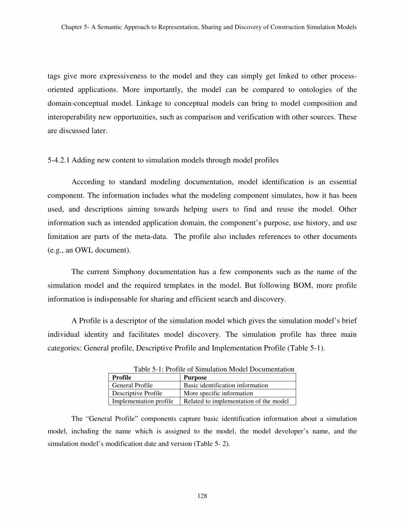
Chapter 5- A Semantic Approach to Representation, Sharing and Discovery of Construction Simulation Models
128
tags give more expressiveness to the model and they can simply get linked to other process-
oriented applications. More importantly, the model can be compared to ontologies of the
domain-conceptual model. Linkage to conceptual models can bring to model composition and
interoperability new opportunities, such as comparison and verification with other sources. These
are discussed later.
5-4.2.1 Adding new content to simulation models through model profiles
According to standard modeling documentation, model identification is an essential
component. The information includes what the modeling component simulates, how it has been
used, and descriptions aiming towards helping users to find and reuse the model. Other
information such as intended application domain, the component’s purpose, use history, and use
limitation are parts of the meta-data. The profile also includes references to other documents
(e.g., an OWL document).
The current Simphony documentation has a few components such as the name of the
simulation model and the required templates in the model. But following BOM, more profile
information is indispensable for sharing and efficient search and discovery.
A Profile is a descriptor of the simulation model which gives the simulation model’s brief
individual identity and facilitates model discovery. The simulation profile has three main
categories: General profile, Descriptive Profile and Implementation Profile (Table 5-1).
Table 5-1: Profile of Simulation Model Documentation Profile Purpose
General Profile Basic identification information
Descriptive Profile More specific information
Implementation profile Related to implementation of the model
The “General Profile” components capture basic identification information about a simulation
model, including the name which is assigned to the model, the model developer’s name, and the
simulation model’s modification date and version (Table 5- 2).

Chapter 5- A Semantic Approach to Representation, Sharing and Discovery of Construction Simulation Models
129
Table 5-2: General Profile Descriptors Profile component Profile component Description
General Profile
Name of Model Name assigned to the model
Model Developer Name of developer & contact information
Modification Date Date of modification
Version Version of the model
The “Descriptive Profile” component provides more specific information about the simulation
model. The model’s application domain is specified and more detailed specifications, such as the client or
modeling case, are provided. Finally, the ontologies related to the model are stated (Table 5- 3).
Table 5-3: Descriptive Profile Descriptors Profile component Profile component Description
Descriptive Profile
Application Domain Which construction operation the model is
presenting, for example spool fabrication.
Description A brief description of modeling purpose.
Ontologies Ontolgies related to the model.
The “Implementation Profile” component provides information related to implementing
the simulation model. A few components are about the version of the simulation tool (Simphony)
and the rest present the simulation model or XML document URI and the model’s location. In
Simphony, multiple templates can be used for developing one model. The required template
component provides the link to those sources. Another thing is that in most simulation models,
the data comes from a database. In document dependencies, the location of those documents is
provided. Finally, if there are any software dependencies for model implementation is specified
at the end (Table 5- 4).
Table 5-4: Implementation Profile Descriptors
Profile component Profile component Description
About Simulation tool Software version and built.
Security classification Simulation content restrictions (0-5
rating).
URIs The URI where simulation model XML
document can be located for use.

Chapter 5- A Semantic Approach to Representation, Sharing and Discovery of Construction Simulation Models
130
Implementation Profile Location of the source model Name of developer & contact
information
Required templates The templates which the model is
dependent on.
Document dependencies The documents which the simulation
model is dependent for execution.
Software dependencies The software dependencies.
5-4.3 XML to RDF/OWL transformation
The XML to OWL transformation is implemented to make the simulation models
processable by semantic web tools and techniques. This is done through a basic mapping
between simulation models meta-data to the model ontology. As shown in the following Table 5-
5, the XML element is mapped to OWL class, XML attributes to RDF/OWL data-type property,
element instance to instance of the created class and the only relationship expressed in XML is
parent-child relationship is mapped to an object property.
Table 5-5: XML Document Transformation into RDF/OWL
XML model representation Model ontology representation
Element/tag name OWL class
Attribute OWL data-type property
Element instance Instance of created class
Parent-child relationship OWL Object property
After the XML to OWL transformation, simulation models and templates are imported to
the repository as RDF/OWL files. Owl:import is the basic primitive for reusing ontologies. The
imported ontology is not a “copy-and-paste” of the original ontology and any changes in the
import environment are reflected into the original one and vice-versa. An Example these models,
is presented in Appendix IV.
5-4.4 Repository of models
The construction modeling repository mainly contains simulation templates and models
and other relevant sources (Figure 5-5). Simulation templates contain a collection of elements
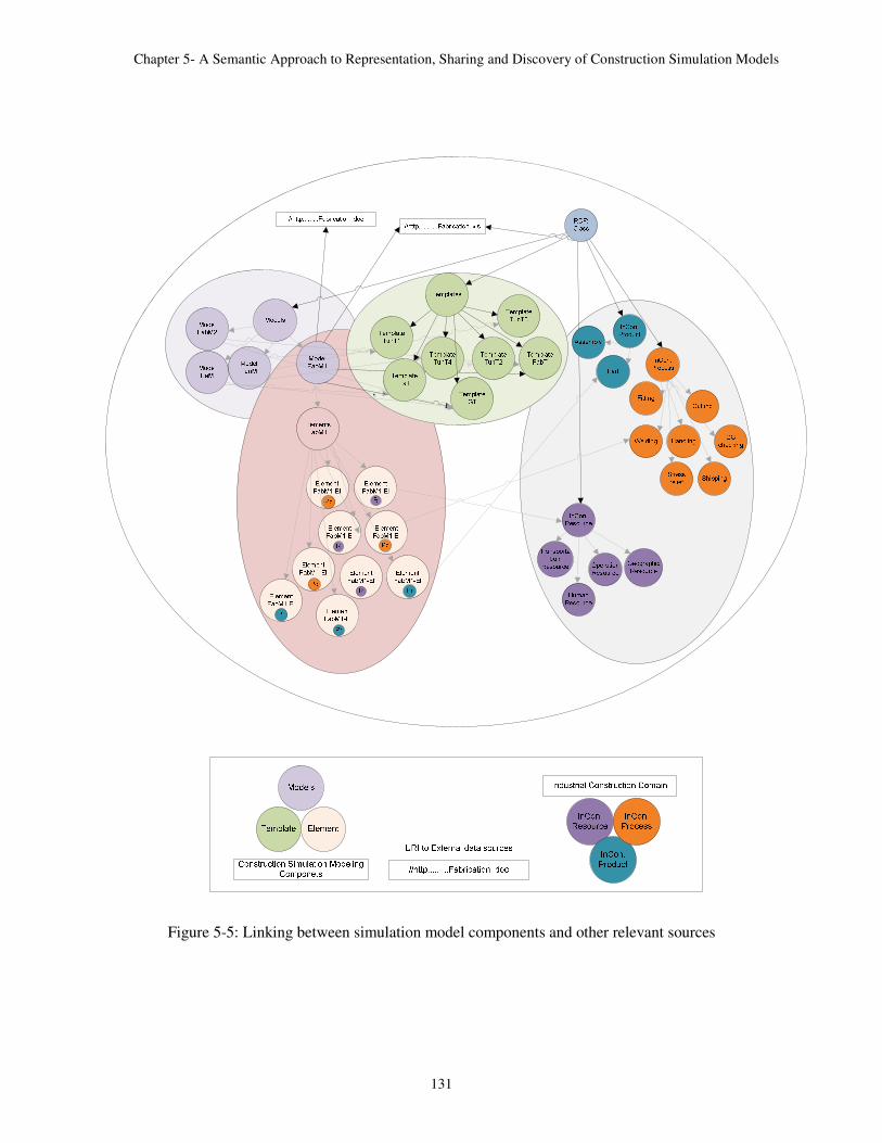
Chapter 5- A Semantic Approach to Representation, Sharing and Discovery of Construction Simulation Models
131
PPR.png
Figure 5-5: Linking between simulation model components and other relevant sources

Chapter 5- A Semantic Approach to Representation, Sharing and Discovery of Construction Simulation Models
132
serving a particular construction simulation domain. The simulation templates’ description
consists of two parts: the template profile and belonging elements. Simulation models, on other
hand, are composed of modeling element instances which can be created from different
templates. Their description contains three parts: model profile; participating elements along
with their different parameters such as input and output parameter, and statistics and their
corresponding values; and the relationships between the elements. All these components reside
in the repository. Sharing and integrating them makes it possible to infer and extract meaningful
information through structuring queries. The discovery process focuses on three main areas:
1- Content of simulation models: Accessing the simulation models and their content is
inevitably important regarding both the use and reuse of models. The modeling content,
such as simulation components and their properties and relationships taking place in the
simulation model, can be dug out through the semantic web without the need for any
other application. The queries can be quantitative or qualitative.
2- Related sources of information: inquiring about other sources of information (e.g.,
domain ontologies, documents, spread sheet, videos) is possible through the cited links
within the simulation models.
3- Model interoperability with other sources: Accessing other sources is not just limited to
their URI, but can be extended to their content. This opens up new means for model
comparison and verification. For example, the semantics of the model can be verified
with the domain ontologies’ content.
Figure 5-6 summarizes the entire process of semantic representation and discovery of simulation
models.

Chapter 5- A Semantic Approach to Representation, Sharing and Discovery of Construction Simulation Models
133
Figure 5-6: Representation and discovery process of simulation models
5-4.5 Semantic repository for construction operations simulation modeling
The prototype repository of construction simulation models has been developed in order
to evaluate the discovery environment’s usability and performance. The simulation models are
stored within ontologies using RDF and OWL syntax and accessed through SPARQL queries.
The prototype repository, as shown in the following figures, contains 7 templates and 4 models..
The repository has been built using TopBraid Composer (TBC) (2010) and Protégé (2006) tools.
Figure 5-7 to 5-10 represent different repository members in TBC.
Figure 5-7 shows different templates which are imported to the repository, Figure 5-8
depicts different components of a simulation element (PipeWorkStation) from an instance of
spool fabrication model built from spool fabrication template. As it is shown the
PipeWorlStation element is an instance of class element and has related inputs, outputs, files and
statistics.

Chapter 5- A Semantic Approach to Representation, Sharing and Discovery of Construction Simulation Models
134
Figure 5-9 shows different elements of earth moving template. Figure 5-10 shows the
repository before and after importing a model into it. In 5-10-1 different modeling classes are
shown and in 5-10-2 different modeling classes are instantiated with tunneling model
components.
Figure 5-7: RDF graph representing the templates in the repository

Chapter 5- A Semantic Approach to Representation, Sharing and Discovery of Construction Simulation Models
135
Figure 5-8: RDF graph of spool fabrication model components

Chapter 5- A Semantic Approach to Representation, Sharing and Discovery of Construction Simulation Models
136
Figure 5-9: RDF graph of earth moving elements

Chapter 5- A Semantic Approach to Representation, Sharing and Discovery of Construction Simulation Models
(1)Modeling Class
Figure 5-11 presents the RDF graph
contains different components of model profile such as general, descriptive and implementation
profile and the values for the specific example.
A Semantic Approach to Representation, Sharing and Discovery of Construction Simulation Models
137
(2)Class instances for tunneling model
Figure 5-10: Snapshot of repository
11 presents the RDF graph for spool fabrication model profile. As
contains different components of model profile such as general, descriptive and implementation
profile and the values for the specific example.
A Semantic Approach to Representation, Sharing and Discovery of Construction Simulation Models
(2)Class instances for tunneling model
for spool fabrication model profile. As it is shown it
contains different components of model profile such as general, descriptive and implementation

Chapter 5- A Semantic Approach to Representation, Sharing and Discovery of Construction Simulation Models
Figure 5
A Semantic Approach to Representation, Sharing and Discovery of Construction Simulation Models
138
Figure 5-11: RDF graph of Models’ profile
A Semantic Approach to Representation, Sharing and Discovery of Construction Simulation Models

Chapter 5- A Semantic Approach to Representation, Sharing and Discovery of Construction Simulation Models
139
Table 5-6 contains some statistics on the repository and its different components. The
repository contains 7 templates and 4 models with the total number of 7995 RDF resources.
Table 5- 6: Construction Repository Statistics
Item
Nu
mb
er
Name of Resource
Ty
pe
of
reso
urc
e (m
od
el
or
tem
pla
te)
Nam
esp
ace
To
tal
nu
mb
er o
f
reso
urc
es (
rdfs
:Res
ou
rce)
Nu
mb
er o
f (o
wl:
thin
g)
Nu
mb
er o
f
(ow
l:D
atat
yp
ePro
per
ty)
Repository 7995 7042 327
1 Tunnelling_Model Model TunM 4457 4148 101
2 Tunnelling_Template_ Shaft_Construction Template TunT1 297 68 30
3 Tunnelling_Template _Support Template TunT2 305 74 31
4 Tunnelling_Template_ Tunnel Template TunT3 481 244 38
5 Tunnelling_Template_Weather_Generation Template TunT4 261 32 30
6 Earthmoving_Model Model EaM 356 109 41
7 Earthmoving_Template Template EaT 317 93 26
8 General_Template Template GT 447 212 32
9 Spool_Fabrication_Template Template FabT 321 95 27
10 Spool_Fabrication_Model_M1 Model FabM1 1378 1125 43
11 Spool_Fabrication_Model_M2 Model FabM2 1155 902 43
12 Related Documents Documents - 5 - -
In order to write queries, it is beneficial to be aware of the overall meta-data of the
ontology; however, despite regular query languages the queries could be written meta-data
oblivious. In this type of query, multiple variables are allowed in one query and the returned
results are based on the restrictions specified in the query. The logic behind this is that SPARQL
is an RDF query language. RDF documents are constructed based on triples. As long as the
variables are linked with each other through the triples, the unknown can be found through the
known components.
Table 5-7 contains sample queries expressed in SPARQL. The results are the matching
simulation components retrieved from the modeling repository. Table 5-8 shows Q6 query
syntax and results displayed in TBC. The rest of queries can be found in Appendix V.

Chapter 5- A Semantic Approach to Representation, Sharing and Discovery of Construction Simulation Models
140
Table 5-7: Queries for Knowledge Retrieval from the Repository
# Query Explanation
Q1 What are the models and templates in the repository
and which domain do they belong to?
Repository content
Q2 What are “Descriptive Profile” properties and what
are the properties’ values for the “Spool
Fabrication” Model?
Profile of a model
Q3 Find the simulation component which has the
“Resource” role in the “Spool Fabrication” model.
And also “objects” in industrial construction
domain ontology under “resource”
Semantic role of simulation components and
comparison with linked data
Q4 Find simulation elements with “process” role which
contain inputs regarding “resources” in the “spool
fabrication” model.
Semantic role of simulation components
Q5 What are required templates for developing a
model of “Tunnelling operations”?
The query returns the URI of the supporting
documents.
Q6 What are the differences between two models of
“Spool Fabrication Shops”?
Comparing two ontologies through querying
two ontolgies at the same time through linking
resources.
Q7 In the properties of “tunnelling” profile and search
if there is any “document” related properties and if
there is what’s the document URI?
The result is the URIs of related documents.
Q8 Which models consider work shifts in their
simulation components?
Investigative queries to get to know the
simulation content.
Q9 Find the Simulation element instances in the
“Tunnelling model” which their output is involved
with Cost>30000.
Investigative queries to get to know the
simulation content.
Q10 Find the Simulation “work station” instances in
Spool fabrication which are operating with more
than 2 workers.
Investigative queries to get to know the
simulation content.
Table 5-8: Sample Query and Results in TBC
# Query Result
Q6

Chapter 5- A Semantic Approach to Representation, Sharing and Discovery of Construction Simulation Models
141
5-5 Summary
The innovative approach presented in this chapter blends semantic web technologies and
construction simulation models for meaningful storage, sharing, and discovery of construction
simulation models. It also properly links the models to their related information sources. The
repository of simulation models contains three main components: composed models of
construction processes, templates containing simulation components, and related data and
information sources. Model discovery is achieved by the web service semantic search. Merging
the semantic web into the construction simulation modeling some of its outcomes are: i) easy
storage and accessibility of models, ii) knowledge extraction from simulation model content iii)
access to data and knowledge sources. The benefits of the semantic web have been briefly
investigated; there can be many other advantages to simulation model reuse, composability, and
interoperability.
5-6 References
Aronson, J., and P. Bose., 1999. “A Model-Based Approach to Simulation Composition”. In
SSR, edited by M. Jazayeri, A. Mili, and R. Mittermeir, 73–82
Chreyh, R., and G. Wainer., 2009. “CD++ Repository: An Internet Based Searchable
Database of DEVS Models and Their Experimental Frames”. In Proceedings of the Spring
Simulation Conference, edited by G. Wainer and M. Chinni, 13–21. San Diego, USA.
Bell, D., de Cesare, S., & Lycett, M., 2005. Semantic transformation of web services. In
OTM 2005—SWWS 2005, vol. 3662, 856–865.
BOM – Base Object Model. Web Site: http://www.boms.info/ Accessed November 2010
Berners-Lee, T., J. Hendler, and O. Lassila. 2001. “The Semantic Web”, Scientific
American, May 2001, 35-43.
Fishwick, P. A. and Miller, J. A., 2004, “Ontologies for Modeling and Simulation: Issues
and Approaches”, Proceedings of the 2004 Winter Simulation Conference, Washington, DC,
259-264.

Chapter 5- A Semantic Approach to Representation, Sharing and Discovery of Construction Simulation Models
142
Garcia Lozano, M., Moradi, F. Ibarzabal, E., and Tjörnhammar, E., 2007, “A Semantic
Approach to Simulation Component Identification and Discovery”, Proceedings of the 21st
European Modeling and Simulation Symposium
Gustavson, P., Chase T., 2007, “Building composable bridges between the conceptual space
and the implementation space”, Proceedings Winter Simulation Conference, 804-814
Halpin, D. W., Jen, H. and Kim., J., 2003, “A construction process simulation web service”,
Proceeding of 35th Winter Simulation Conference, 1503-1509
Hajjar, D., and AbouRizk, S., 1999, “Simphony: An environment for building special
purpose construction simulation tools”, Proceeding of 31th Winter Simulation Conference, 998 -
1006
Lacy, L. W., 2005a, “PIMODES”. 37th Winter Simulation Conference (Doctoral
Symposium).
Lacy, L. W., 2005b, “PIMODES”. Fourth International Semantic Web Conference Doctoral
Symposium. Galway, Ireland.
Protégé, 2010, ed: Stanford Center for Biomedical Informatics Research
McGuinness, D. L. and F. Harmelen., 2004, “OWL Web Ontology Language Overview”
[online]. Available via < http://www.w3.org/TR/owl-features/ >
Robinson, S. (2006). “Conceptual modeling for simulation: Issues and research
requirements”, Proceedings of the 2006 Winter Simulation Conference, 792 - 800
Robinson, S., Nance, R. E., Paul, R. J., Pidd, M. and Taylor, S. J. E, 2004, “Simulation
model reuse: Definitions, benefits and obstacles” Simulation Modelling Practice and Theory, vol.
12, no. 7–8, 479–494
Silver, G., O. Hassan, J. Miller., 2007, “From Domain Ontologies to Modeling Ontologies to
Executable Simulation Models”, In Proceedings of the 2007 Winter Simulation Conference,
1108 - 1117
Tolk, A., and Turnitsa, C. D., 2007, “Conceptual modeling of information exchange
requirements based on ontological means”, Proceeding of 39th Winter Simulation Conference,
1100-1107
TopBraid Composer, 2010, ed: TopQuadrant, Inc
W3C. XML., http://www.w3.org/TR/xml/, Accessed 2012-01-21
W3C. Semantic Web,http://www.w3.org/2004/OWL/, Accessed 2012-01-21

143
Chapter 6
Conclusion
The research described in the thesis was motivated by a lack of reuse and interoperability of
construction simulation models. Construction simulation models are knowledge intensive and are
built up on construction domain knowledge and simulation modeling knowledge. The objective
of this research was to capitalize on this embedded knowledge and effectively share and reuse it.
The research focuses on two main areas: capture and representation of construction processes
and simulation modeling, and simulation and modeling knowledge retrieval.
The study began by determining different simulation aspects in which modeling sharing and
reuse could be enhanced. The first was conceptual modelling, which is the representation means
of the acquired industrial construction knowledge. The second was the modeling development
process, while utilizing HLA-based distributed simulation modeling environment. The third was
reuse of the models that already are developed. Chapters 3, 4 and 5 consequently presented these
areas.
Chapter 2 presented the industrial construction domain and the models addressing the challenges
of the domain. In Chapter 3 the conceptual model of the industrial construction domain is
captured and formalized through its ontological model containing concepts’ hierarchies and
relationships between them for further extraction and reuse in the simulation development
process. Chapter 3 investigated reusability challenges through the modeling process, especially

Chapter 6- Conclusion
144
for the HLA-based distributed simulation modeling environments. In Chapter 5, the focus was on
facilitating the reuse of models by introducing a new means for accessing, sharing, presenting,
and discovering simulation models in a domain.
Thesis contributions:
1- Studying reuse through the entire simulation life cycle
This study for the first time utilized semantic web technology and techniques through the
entire life cycle of simulation modeling. It is expected that this research will initiate more
implementation of ontologies in the construction industry.
2- First attempt to formalize the industrial construction domain through ontologies.
The study introduced formalizing and structuring of the industrial construction domain
knowledge.
3- Sharing and reusing the captured domain knowledge within industrial construction
ontology for the use of applications.
This has been done through mapping related concepts to each other and ultimately
connecting industrial construction domain instances to simulation modeling element
instances.
4- Ontological approach towards facilitating reuse within distributed simulation modeling.
An ontological framework was utilized to facilitate a collaborative environment. An
example of this is shown for developing a federation object model, which is shared
between all the simulation modeling components (federates). Moreover, an element-
based development approach is employed for the distributed simulation model
components, to facilitate reuse through the development process.

Chapter 6- Conclusion
145
5- Using the semantic web for storing, sharing, and reuse and discovery of developed
construction models.
The innovative architecture blends semantic web technologies and construction
simulation models presented in a machine-interpretable metadata for storing, sharing, and
discovering construction simulation models and properly linking them to their related
information sources.
6-1 Recommendations for future work:
1- This research also provides a knowledge-based foundation through the entire life-cycle of
construction simulation modeling. Also, it is applicable for any knowledge-intensive
application.
2- In order to evaluate the industrial domain ontology, it should be put into use. The
ontology can be modified and extended according to new needs. The best practice for
accomplishing this is to provide the ontology of domain knowledge as a wiki for
interested parties. A wiki is a collaborative website designed to enable domain exports to
access and contribute or modify the website’s content. Important parts which have to be
added to the ontology are domain projects and lessons learnt in different areas. This will
lead to an invaluable source of knowledge for the construction industry.
3- The semantic web offers an important opportunity to compose simulation models from
existing simulation components. The simulation components stored in simulation
repositories can be discovered based on a specific simulation scenario and glued to each
other to build a simulation model. This is an interesting area to be investigated.
4- Linking models to related sources can be extended without limitations. Moreover the
access to these sources can easily exceed from their URLs to their contents. Shifting from

Chapter 6- Conclusion
146
a document to its content brings powerful features for model interoperability, discovery
and simulation models’ knowledge extraction process.

147
Appendix I
XML/RDF Source Code of InCon-Onto
<?xml version="1.0"?>
<!DOCTYPE rdf:RDF [
<!ENTITY owl "http://www.w3.org/2002/07/owl#" >
<!ENTITY swrl "http://www.w3.org/2003/11/swrl#" >
<!ENTITY swrlb "http://www.w3.org/2003/11/swrlb#" >
<!ENTITY xsd "http://www.w3.org/2001/XMLSchema#" >
<!ENTITY rdfs "http://www.w3.org/2000/01/rdf-schema#" >
<!ENTITY rdf "http://www.w3.org/1999/02/22-rdf-syntax-ns#" >
<!ENTITY protege "http://protege.stanford.edu/plugins/owl/protege#" >
<!ENTITY xsp "http://www.owl-ontologies.com/2005/08/07/xsp.owl#" >
<!ENTITY InCon "http://www.owl-ontologies.com/Ontology1291499709.owl#" >
]>
<rdf:RDF xmlns="http://www.owl-ontologies.com/Ontology1291499710.owl#"
xml:base="http://www.owl-ontologies.com/Ontology1291499710.owl"
xmlns:rdfs="http://www.w3.org/2000/01/rdf-schema#"
xmlns:swrl="http://www.w3.org/2003/11/swrl#"
xmlns:protege="http://protege.stanford.edu/plugins/owl/protege#"
xmlns:InCon="http://www.owl-ontologies.com/Ontology1291499709.owl#"
xmlns:xsp="http://www.owl-ontologies.com/2005/08/07/xsp.owl#"
xmlns:owl="http://www.w3.org/2002/07/owl#"
xmlns:xsd="http://www.w3.org/2001/XMLSchema#"
xmlns:swrlb="http://www.w3.org/2003/11/swrlb#"
xmlns:rdf="http://www.w3.org/1999/02/22-rdf-syntax-ns#">
<owl:Ontology rdf:about=""/>
<InCon:Construction_site rdf:about="&InCon;Access_path">
<InCon:belonging_domain rdf:resource="&InCon;Tunneling_Construction_Operation"/>
</InCon:Construction_site>
<InCon:Management_product rdf:about="&InCon;As_built_drawing">
<rdfs:subClassOf rdf:resource="&InCon;Drawing"/>
<InCon:belonging_domain rdf:resource="&InCon;Construction_operation"/>
</InCon:Management_product>
<owl:Class rdf:about="&InCon;Aspect">

Appendix I- InCon-Onto XML/RDF Source Code
148
<rdfs:subClassOf rdf:resource="&owl;Class"/>
<rdfs:subClassOf>
<owl:Restriction>
<owl:onProperty rdf:resource="&InCon;is_an_aspect"/>
<owl:someValuesFrom>
<owl:Class>
<owl:unionOf rdf:parseType="Collection">
<owl:Class rdf:about="&InCon;Process"/>
<owl:Class rdf:about="&InCon;Product"/>
</owl:unionOf>
</owl:Class>
</owl:someValuesFrom>
</owl:Restriction>
</rdfs:subClassOf>
<rdfs:subClassOf>
<owl:Restriction>
<owl:onProperty rdf:resource="&InCon;has_scale"/>
<owl:someValuesFrom rdf:resource="&InCon;Scale"/>
</owl:Restriction>
</rdfs:subClassOf>
</owl:Class>
<owl:Class rdf:about="&InCon;Assembly">
<rdfs:subClassOf>
<owl:Restriction>
<owl:onProperty rdf:resource="&InCon;composed_of"/>
<owl:someValuesFrom>
<owl:Class>
<owl:unionOf rdf:parseType="Collection">
<owl:Class rdf:about="&InCon;Assembly"/>
<owl:Class rdf:about="&InCon;Part"/>
</owl:unionOf>
</owl:Class>
</owl:someValuesFrom>
</owl:Restriction>
</rdfs:subClassOf>
<rdfs:subClassOf rdf:resource="&InCon;Industrial_construction_product"/>
<rdfs:subClassOf>
<owl:Restriction>
<owl:onProperty rdf:resource="&InCon;is_accomplished_by"/>
<owl:minCardinality rdf:datatype="&xsd;nonNegativeInteger">2</owl:minCardinality>
</owl:Restriction>
</rdfs:subClassOf>
</owl:Class>
<InCon:Machine_resouce rdf:about="&InCon;Auger_boring">
<InCon:belonging_domain rdf:resource="&InCon;Tunneling_Construction_Operation"/>
</InCon:Machine_resouce>
<owl:Class rdf:about="&InCon;Bay">
<rdfs:subClassOf rdf:resource="&InCon;Site"/>
</owl:Class>
<owl:ObjectProperty rdf:about="&InCon;belonging_aspect">
<rdf:type rdf:resource="&owl;FunctionalProperty"/>
<rdfs:domain rdf:resource="&InCon;Scale"/>
<owl:inverseOf rdf:resource="&InCon;has_scale"/>
<rdfs:range rdf:resource="&InCon;Aspect"/>
</owl:ObjectProperty>

Appendix I- InCon-Onto XML/RDF Source Code
149
<owl:ObjectProperty rdf:about="&InCon;belonging_domain">
<rdfs:domain>
<owl:Class>
<owl:unionOf rdf:parseType="Collection">
<owl:Class rdf:about="&InCon;Product"/>
<owl:Class rdf:about="&InCon;Resource"/>
</owl:unionOf>
</owl:Class>
</rdfs:domain>
<rdfs:range rdf:resource="&InCon;Construction_operation"/>
</owl:ObjectProperty>
<InCon:Worker rdf:about="&InCon;Boilemaker">
<InCon:belonging_domain rdf:resource="&InCon;Industrial_Construction_Operation"/>
</InCon:Worker>
<owl:Class rdf:about="&InCon;Building">
<rdfs:subClassOf rdf:resource="&InCon;Geographic_resource"/>
</owl:Class>
<owl:Class rdf:about="&InCon;Building_zone">
<rdfs:subClassOf rdf:resource="&InCon;Geographic_resource"/>
</owl:Class>
<InCon:Industrial_Construction_Operation rdf:about="&InCon;Cable_tray">
<rdfs:subClassOf rdf:resource="&InCon;Module_assembly"/>
</InCon:Industrial_Construction_Operation>
<InCon:Worker rdf:about="&InCon;Carpenter">
<InCon:belonging_domain rdf:resource="&InCon;Industrial_Construction_Operation"/>
</InCon:Worker>
<owl:ObjectProperty rdf:about="&InCon;composed_of">
<rdf:type rdf:resource="&owl;TransitiveProperty"/>
<rdfs:domain rdf:resource="&InCon;Assembly"/>
<owl:inverseOf rdf:resource="&InCon;part_of"/>
<rdfs:range>
<owl:Class>
<owl:unionOf rdf:parseType="Collection">
<owl:Class rdf:about="&InCon;Assembly"/>
<owl:Class rdf:about="&InCon;Part"/>
</owl:unionOf>
</owl:Class>
</rdfs:range>
</owl:ObjectProperty>
<InCon:Industrial_Construction_Operation rdf:about="&InCon;Concrete_work">
<rdfs:subClassOf rdf:resource="&InCon;Site_construction"/>
</InCon:Industrial_Construction_Operation>
<owl:Class rdf:about="&InCon;Construction_operation">
<rdfs:subClassOf rdf:resource="&InCon;Process"/>
</owl:Class>
<owl:Class rdf:about="&InCon;Construction_product">
<rdfs:subClassOf rdf:resource="&InCon;Product"/>
</owl:Class>
<owl:Class rdf:about="&InCon;Construction_site">
<rdfs:subClassOf rdf:resource="&InCon;Site"/>
</owl:Class>
<InCon:Handling_resource rdf:about="&InCon;Crane">
<InCon:belonging_domain rdf:resource="&InCon;Construction_operation"/>
</InCon:Handling_resource>
<InCon:Worker rdf:about="&InCon;Cutter">
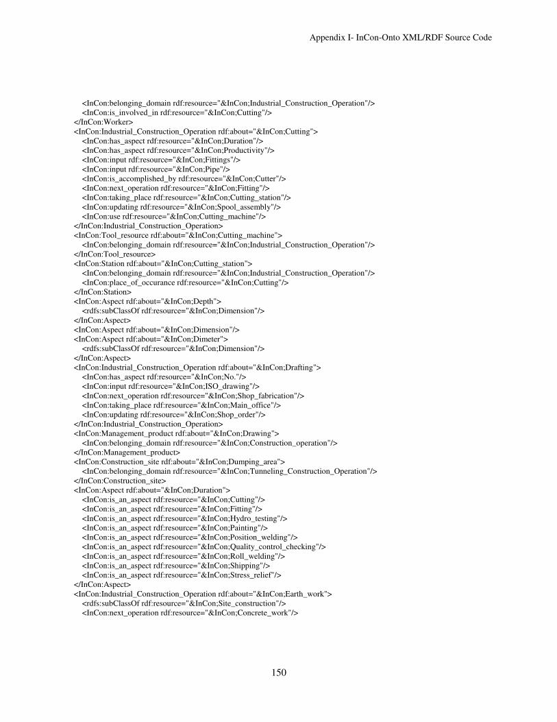
Appendix I- InCon-Onto XML/RDF Source Code
150
<InCon:belonging_domain rdf:resource="&InCon;Industrial_Construction_Operation"/>
<InCon:is_involved_in rdf:resource="&InCon;Cutting"/>
</InCon:Worker>
<InCon:Industrial_Construction_Operation rdf:about="&InCon;Cutting">
<InCon:has_aspect rdf:resource="&InCon;Duration"/>
<InCon:has_aspect rdf:resource="&InCon;Productivity"/>
<InCon:input rdf:resource="&InCon;Fittings"/>
<InCon:input rdf:resource="&InCon;Pipe"/>
<InCon:is_accomplished_by rdf:resource="&InCon;Cutter"/>
<InCon:next_operation rdf:resource="&InCon;Fitting"/>
<InCon:taking_place rdf:resource="&InCon;Cutting_station"/>
<InCon:updating rdf:resource="&InCon;Spool_assembly"/>
<InCon:use rdf:resource="&InCon;Cutting_machine"/>
</InCon:Industrial_Construction_Operation>
<InCon:Tool_resource rdf:about="&InCon;Cutting_machine">
<InCon:belonging_domain rdf:resource="&InCon;Industrial_Construction_Operation"/>
</InCon:Tool_resource>
<InCon:Station rdf:about="&InCon;Cutting_station">
<InCon:belonging_domain rdf:resource="&InCon;Industrial_Construction_Operation"/>
<InCon:place_of_occurance rdf:resource="&InCon;Cutting"/>
</InCon:Station>
<InCon:Aspect rdf:about="&InCon;Depth">
<rdfs:subClassOf rdf:resource="&InCon;Dimension"/>
</InCon:Aspect>
<InCon:Aspect rdf:about="&InCon;Dimension"/>
<InCon:Aspect rdf:about="&InCon;Dimeter">
<rdfs:subClassOf rdf:resource="&InCon;Dimension"/>
</InCon:Aspect>
<InCon:Industrial_Construction_Operation rdf:about="&InCon;Drafting">
<InCon:has_aspect rdf:resource="&InCon;No."/>
<InCon:input rdf:resource="&InCon;ISO_drawing"/>
<InCon:next_operation rdf:resource="&InCon;Shop_fabrication"/>
<InCon:taking_place rdf:resource="&InCon;Main_office"/>
<InCon:updating rdf:resource="&InCon;Shop_order"/>
</InCon:Industrial_Construction_Operation>
<InCon:Management_product rdf:about="&InCon;Drawing">
<InCon:belonging_domain rdf:resource="&InCon;Construction_operation"/>
</InCon:Management_product>
<InCon:Construction_site rdf:about="&InCon;Dumping_area">
<InCon:belonging_domain rdf:resource="&InCon;Tunneling_Construction_Operation"/>
</InCon:Construction_site>
<InCon:Aspect rdf:about="&InCon;Duration">
<InCon:is_an_aspect rdf:resource="&InCon;Cutting"/>
<InCon:is_an_aspect rdf:resource="&InCon;Fitting"/>
<InCon:is_an_aspect rdf:resource="&InCon;Hydro_testing"/>
<InCon:is_an_aspect rdf:resource="&InCon;Painting"/>
<InCon:is_an_aspect rdf:resource="&InCon;Position_welding"/>
<InCon:is_an_aspect rdf:resource="&InCon;Quality_control_checking"/>
<InCon:is_an_aspect rdf:resource="&InCon;Roll_welding"/>
<InCon:is_an_aspect rdf:resource="&InCon;Shipping"/>
<InCon:is_an_aspect rdf:resource="&InCon;Stress_relief"/>
</InCon:Aspect>
<InCon:Industrial_Construction_Operation rdf:about="&InCon;Earth_work">
<rdfs:subClassOf rdf:resource="&InCon;Site_construction"/>
<InCon:next_operation rdf:resource="&InCon;Concrete_work"/>

Appendix I- InCon-Onto XML/RDF Source Code
151
</InCon:Industrial_Construction_Operation>
<InCon:Industrial_Construction_Operation rdf:about="&InCon;Electrical">
<rdfs:subClassOf rdf:resource="&InCon;Module_assembly"/>
<rdfs:subClassOf rdf:resource="&InCon;Site_construction"/>
</InCon:Industrial_Construction_Operation>
<owl:Class rdf:about="&InCon;Employee">
<rdfs:subClassOf rdf:resource="&InCon;Human_resouce"/>
</owl:Class>
<InCon:Industrial_Construction_Operation rdf:about="&InCon;Equipment">
<rdfs:subClassOf rdf:resource="&InCon;Module_assembly"/>
<InCon:next_operation rdf:resource="&InCon;Piping"/>
</InCon:Industrial_Construction_Operation>
<InCon:Construction_site rdf:about="&InCon;Equipment_storage_area">
<InCon:belonging_domain rdf:resource="&InCon;Tunneling_Construction_Operation"/>
</InCon:Construction_site>
<InCon:Management_product rdf:about="&InCon;Erection_order">
<InCon:belonging_domain rdf:resource="&InCon;Industrial_Construction_Operation"/>
</InCon:Management_product>
<InCon:Shop_floor rdf:about="&InCon;Fabrication_shop">
<InCon:belonging_domain rdf:resource="&InCon;Industrial_Construction_Operation"/>
<InCon:place_of_occurance rdf:resource="&InCon;Quality_control_checking"/>
<InCon:place_of_occurance rdf:resource="&InCon;Shipping"/>
<InCon:place_of_occurance rdf:resource="&InCon;Shop_fabrication"/>
<InCon:place_of_occurance rdf:resource="&InCon;Stress_relief"/>
</InCon:Shop_floor>
<InCon:Industrial_Construction_Operation rdf:about="&InCon;Fire_profing">
<rdfs:subClassOf rdf:resource="&InCon;Module_assembly"/>
<InCon:next_operation rdf:resource="&InCon;Module_preparation"/>
</InCon:Industrial_Construction_Operation>
<InCon:Industrial_Construction_Operation rdf:about="&InCon;Fitting">
<InCon:has_aspect rdf:resource="&InCon;Duration"/>
<InCon:has_aspect rdf:resource="&InCon;Productivity"/>
<InCon:input rdf:resource="&InCon;Fittings"/>
<InCon:input rdf:resource="&InCon;Pipe"/>
<InCon:input rdf:resource="&InCon;Spool_assembly"/>
<InCon:is_accomplished_by rdf:resource="&InCon;Pipe_fitter"/>
<InCon:next_operation rdf:resource="&InCon;Roll_welding"/>
<InCon:taking_place rdf:resource="&InCon;Fitting_station"/>
<InCon:updating rdf:resource="&InCon;Spool_assembly"/>
<InCon:use rdf:resource="&InCon;Fitting_weld_positioner"/>
</InCon:Industrial_Construction_Operation>
<InCon:Station rdf:about="&InCon;Fitting_station">
<InCon:belonging_domain rdf:resource="&InCon;Industrial_Construction_Operation"/>
<InCon:place_of_occurance rdf:resource="&InCon;Fitting"/>
</InCon:Station>
<InCon:Tool_resource rdf:about="&InCon;Fitting_weld_positioner">
<InCon:belonging_domain rdf:resource="&InCon;Industrial_Construction_Operation"/>
</InCon:Tool_resource>
<InCon:Part rdf:about="&InCon;Fittings">
<InCon:belonging_domain rdf:resource="&InCon;Industrial_Construction_Operation"/>
<InCon:input_of rdf:resource="&InCon;Cutting"/>
<InCon:input_of rdf:resource="&InCon;Fitting"/>
<InCon:part_of rdf:resource="&InCon;Spool_assembly"/>
</InCon:Part>
<InCon:Tool_resource rdf:about="&InCon;Fixed_welding_positioner">

Appendix I- InCon-Onto XML/RDF Source Code
152
<InCon:belonging_domain rdf:resource="&InCon;Industrial_Construction_Operation"/>
</InCon:Tool_resource>
<owl:Class rdf:about="&InCon;Geographic_resource">
<rdfs:subClassOf rdf:resource="&InCon;Resource"/>
<rdfs:subClassOf>
<owl:Restriction>
<owl:onProperty rdf:resource="&InCon;place_of_occurance"/>
<owl:someValuesFrom rdf:resource="&InCon;Process"/>
</owl:Restriction>
</rdfs:subClassOf>
</owl:Class>
<owl:Class rdf:about="&InCon;Handling_resource">
<rdfs:subClassOf rdf:resource="&InCon;Operational_resouce"/>
</owl:Class>
<owl:ObjectProperty rdf:about="&InCon;has_aspect">
<rdfs:domain>
<owl:Class>
<owl:unionOf rdf:parseType="Collection">
<owl:Class rdf:about="&InCon;Process"/>
<owl:Class rdf:about="&InCon;Product"/>
<owl:Class rdf:about="&InCon;Resource"/>
</owl:unionOf>
</owl:Class>
</rdfs:domain>
<owl:inverseOf rdf:resource="&InCon;is_an_aspect"/>
<rdfs:range rdf:resource="&InCon;Aspect"/>
</owl:ObjectProperty>
<owl:ObjectProperty rdf:about="&InCon;has_scale">
<rdf:type rdf:resource="&owl;InverseFunctionalProperty"/>
<rdfs:domain rdf:resource="&InCon;Aspect"/>
<owl:inverseOf rdf:resource="&InCon;belonging_aspect"/>
<rdfs:range rdf:resource="&InCon;Scale"/>
</owl:ObjectProperty>
<owl:DatatypeProperty rdf:about="&InCon;has_value">
<rdfs:domain rdf:resource="&InCon;Aspect"/>
<rdfs:range rdf:resource="&xsd;float"/>
</owl:DatatypeProperty>
<InCon:Machine_resouce rdf:about="&InCon;HDD">
<InCon:belonging_domain rdf:resource="&InCon;Tunneling_Construction_Operation"/>
</InCon:Machine_resouce>
<InCon:Aspect rdf:about="&InCon;Height">
<rdfs:subClassOf rdf:resource="&InCon;Dimension"/>
</InCon:Aspect>
<InCon:Employee rdf:about="&InCon;HSE_staff">
<InCon:belonging_domain rdf:resource="&InCon;Industrial_Construction_Operation"/>
</InCon:Employee>
<owl:Class rdf:about="&InCon;Human_resouce">
<rdfs:subClassOf rdf:resource="&InCon;Resource"/>
<rdfs:subClassOf>
<owl:Restriction>
<owl:onProperty rdf:resource="&InCon;is_involved_in"/>
<owl:someValuesFrom rdf:resource="&InCon;Process"/>
</owl:Restriction>
</rdfs:subClassOf>
</owl:Class>

Appendix I- InCon-Onto XML/RDF Source Code
153
<InCon:Bay rdf:about="&InCon;Hydro_test_yard">
<InCon:belonging_domain rdf:resource="&InCon;Industrial_Construction_Operation"/>
<InCon:place_of_occurance rdf:resource="&InCon;Hydro_testing"/>
</InCon:Bay>
<InCon:Industrial_Construction_Operation rdf:about="&InCon;Hydro_testing">
<rdfs:subClassOf rdf:resource="&InCon;Shop_fabrication"/>
<InCon:has_aspect rdf:resource="&InCon;Duration"/>
<InCon:has_aspect rdf:resource="&InCon;Productivity"/>
<InCon:input rdf:resource="&InCon;Spool_assembly"/>
<InCon:is_accomplished_by rdf:resource="&InCon;Quality_control_worker"/>
<InCon:next_operation rdf:resource="&InCon;Painting"/>
<InCon:taking_place rdf:resource="&InCon;Hydro_test_yard"/>
<InCon:updating rdf:resource="&InCon;Spool_assembly"/>
</InCon:Industrial_Construction_Operation>
<InCon:Machine_resouce rdf:about="&InCon;Impact_moling">
<InCon:belonging_domain rdf:resource="&InCon;Tunneling_Construction_Operation"/>
</InCon:Machine_resouce>
<owl:Class rdf:about="&InCon;Industrial_Construction_Operation">
<rdfs:subClassOf rdf:resource="&InCon;Construction_operation"/>
</owl:Class>
<owl:Class rdf:about="&InCon;Industrial_construction_product">
<rdfs:subClassOf rdf:resource="&InCon;Product"/>
</owl:Class>
<owl:ObjectProperty rdf:about="&InCon;input">
<rdfs:domain rdf:resource="&InCon;Process"/>
<owl:inverseOf rdf:resource="&InCon;input_of"/>
<rdfs:range rdf:resource="&InCon;Product"/>
</owl:ObjectProperty>
<owl:ObjectProperty rdf:about="&InCon;input_of">
<rdfs:domain rdf:resource="&InCon;Product"/>
<owl:inverseOf rdf:resource="&InCon;input"/>
<rdfs:range rdf:resource="&InCon;Process"/>
</owl:ObjectProperty>
<InCon:Industrial_Construction_Operation rdf:about="&InCon;Instrumentation">
<rdfs:subClassOf rdf:resource="&InCon;Site_construction"/>
</InCon:Industrial_Construction_Operation>
<InCon:Industrial_Construction_Operation rdf:about="&InCon;Insulation">
<rdfs:subClassOf rdf:resource="&InCon;Module_assembly"/>
<rdfs:subClassOf rdf:resource="&InCon;Site_construction"/>
<InCon:next_operation rdf:resource="&InCon;Fire_profing"/>
<InCon:next_operation rdf:resource="&InCon;Mechanical_equipment"/>
</InCon:Industrial_Construction_Operation>
<InCon:Worker rdf:about="&InCon;Ironworker">
<InCon:belonging_domain rdf:resource="&InCon;Industrial_Construction_Operation"/>
</InCon:Worker>
<owl:ObjectProperty rdf:about="&InCon;is_accomplished_by">
<rdfs:domain rdf:resource="&InCon;Process"/>
<owl:inverseOf rdf:resource="&InCon;is_involved_in"/>
<rdfs:range rdf:resource="&InCon;Worker"/>
</owl:ObjectProperty>
<owl:ObjectProperty rdf:about="&InCon;is_an_aspect">
<rdfs:domain rdf:resource="&InCon;Aspect"/>
<owl:inverseOf rdf:resource="&InCon;has_aspect"/>
<rdfs:range>
<owl:Class>

Appendix I- InCon-Onto XML/RDF Source Code
154
<owl:unionOf rdf:parseType="Collection">
<owl:Class rdf:about="&InCon;Process"/>
<owl:Class rdf:about="&InCon;Resource"/>
</owl:unionOf>
</owl:Class>
</rdfs:range>
</owl:ObjectProperty>
<owl:ObjectProperty rdf:about="&InCon;is_involved_in">
<rdfs:domain rdf:resource="&InCon;Worker"/>
<owl:inverseOf rdf:resource="&InCon;is_accomplished_by"/>
<rdfs:range rdf:resource="&InCon;Process"/>
</owl:ObjectProperty>
<owl:ObjectProperty rdf:about="&InCon;is_used">
<rdfs:domain rdf:resource="&InCon;Operational_resouce"/>
<owl:inverseOf rdf:resource="&InCon;use"/>
<rdfs:range rdf:resource="&InCon;Process"/>
</owl:ObjectProperty>
<InCon:Management_product rdf:about="&InCon;ISO_drawing">
<rdfs:subClassOf rdf:resource="&InCon;Drawing"/>
<InCon:belonging_domain rdf:resource="&InCon;Industrial_Construction_Operation"/>
</InCon:Management_product>
<InCon:Worker rdf:about="&InCon;Labourer">
<InCon:belonging_domain rdf:resource="&InCon;Industrial_Construction_Operation"/>
<InCon:is_involved_in rdf:resource="&InCon;Painting"/>
<InCon:is_involved_in rdf:resource="&InCon;Shipping"/>
<InCon:is_involved_in rdf:resource="&InCon;Stress_relief"/>
</InCon:Worker>
<InCon:Aspect rdf:about="&InCon;Length">
<rdfs:subClassOf rdf:resource="&InCon;Dimension"/>
</InCon:Aspect>
<InCon:Management_product rdf:about="&InCon;Lift_order">
<InCon:belonging_domain rdf:resource="&InCon;Industrial_Construction_Operation"/>
</InCon:Management_product>
<InCon:Material_resource rdf:about="&InCon;liner_plate">
<InCon:belonging_domain rdf:resource="&InCon;Tunneling_Construction_Operation"/>
</InCon:Material_resource>
<InCon:Tunneling_Construction_Operation rdf:about="&InCon;Lining">
<InCon:updating rdf:resource="&InCon;Linner"/>
<InCon:updating rdf:resource="&InCon;Undercut"/>
</InCon:Tunneling_Construction_Operation>
<InCon:Tunneling_Product rdf:about="&InCon;Linner">
<InCon:belonging_domain rdf:resource="&InCon;Tunneling_Construction_Operation"/>
<InCon:output_of rdf:resource="&InCon;Lining"/>
</InCon:Tunneling_Product>
<owl:Class rdf:about="&InCon;Lot">
<rdfs:subClassOf rdf:resource="&InCon;Site"/>
</owl:Class>
<owl:Class rdf:about="&InCon;Machine_resouce">
<rdfs:subClassOf rdf:resource="&InCon;Operational_resouce"/>
</owl:Class>
<InCon:Building rdf:about="&InCon;Main_office">
<InCon:belonging_domain rdf:resource="&InCon;Construction_operation"/>
<InCon:place_of_occurance rdf:resource="&InCon;Drafting"/>
</InCon:Building>
<owl:Class rdf:about="&InCon;Management_product">
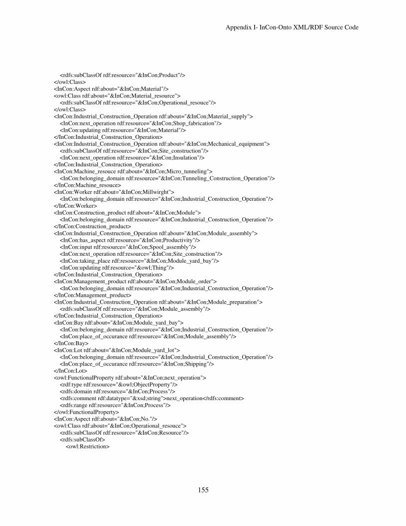
Appendix I- InCon-Onto XML/RDF Source Code
155
<rdfs:subClassOf rdf:resource="&InCon;Product"/>
</owl:Class>
<InCon:Aspect rdf:about="&InCon;Material"/>
<owl:Class rdf:about="&InCon;Material_resource">
<rdfs:subClassOf rdf:resource="&InCon;Operational_resouce"/>
</owl:Class>
<InCon:Industrial_Construction_Operation rdf:about="&InCon;Material_supply">
<InCon:next_operation rdf:resource="&InCon;Shop_fabrication"/>
<InCon:updating rdf:resource="&InCon;Material"/>
</InCon:Industrial_Construction_Operation>
<InCon:Industrial_Construction_Operation rdf:about="&InCon;Mechanical_equipment">
<rdfs:subClassOf rdf:resource="&InCon;Site_construction"/>
<InCon:next_operation rdf:resource="&InCon;Insulation"/>
</InCon:Industrial_Construction_Operation>
<InCon:Machine_resouce rdf:about="&InCon;Micro_tunneling">
<InCon:belonging_domain rdf:resource="&InCon;Tunneling_Construction_Operation"/>
</InCon:Machine_resouce>
<InCon:Worker rdf:about="&InCon;Millwirght">
<InCon:belonging_domain rdf:resource="&InCon;Industrial_Construction_Operation"/>
</InCon:Worker>
<InCon:Construction_product rdf:about="&InCon;Module">
<InCon:belonging_domain rdf:resource="&InCon;Industrial_Construction_Operation"/>
</InCon:Construction_product>
<InCon:Industrial_Construction_Operation rdf:about="&InCon;Module_assembly">
<InCon:has_aspect rdf:resource="&InCon;Productivity"/>
<InCon:input rdf:resource="&InCon;Spool_assembly"/>
<InCon:next_operation rdf:resource="&InCon;Site_construction"/>
<InCon:taking_place rdf:resource="&InCon;Module_yard_bay"/>
<InCon:updating rdf:resource="&owl;Thing"/>
</InCon:Industrial_Construction_Operation>
<InCon:Management_product rdf:about="&InCon;Module_order">
<InCon:belonging_domain rdf:resource="&InCon;Industrial_Construction_Operation"/>
</InCon:Management_product>
<InCon:Industrial_Construction_Operation rdf:about="&InCon;Module_preparation">
<rdfs:subClassOf rdf:resource="&InCon;Module_assembly"/>
</InCon:Industrial_Construction_Operation>
<InCon:Bay rdf:about="&InCon;Module_yard_bay">
<InCon:belonging_domain rdf:resource="&InCon;Industrial_Construction_Operation"/>
<InCon:place_of_occurance rdf:resource="&InCon;Module_assembly"/>
</InCon:Bay>
<InCon:Lot rdf:about="&InCon;Module_yard_lot">
<InCon:belonging_domain rdf:resource="&InCon;Industrial_Construction_Operation"/>
<InCon:place_of_occurance rdf:resource="&InCon;Shipping"/>
</InCon:Lot>
<owl:FunctionalProperty rdf:about="&InCon;next_operation">
<rdf:type rdf:resource="&owl;ObjectProperty"/>
<rdfs:domain rdf:resource="&InCon;Process"/>
<rdfs:comment rdf:datatype="&xsd;string">next_operation</rdfs:comment>
<rdfs:range rdf:resource="&InCon;Process"/>
</owl:FunctionalProperty>
<InCon:Aspect rdf:about="&InCon;No."/>
<owl:Class rdf:about="&InCon;Operational_resouce">
<rdfs:subClassOf rdf:resource="&InCon;Resource"/>
<rdfs:subClassOf>
<owl:Restriction>

Appendix I- InCon-Onto XML/RDF Source Code
156
<owl:onProperty rdf:resource="&InCon;is_used"/>
<owl:someValuesFrom rdf:resource="&InCon;Process"/>
</owl:Restriction>
</rdfs:subClassOf>
</owl:Class>
<InCon:Worker rdf:about="&InCon;Operator">
<InCon:belonging_domain rdf:resource="&InCon;Industrial_Construction_Operation"/>
</InCon:Worker>
<owl:ObjectProperty rdf:about="&InCon;output_of">
<rdfs:domain rdf:resource="&InCon;Product"/>
<owl:inverseOf rdf:resource="&InCon;updating"/>
<rdfs:range rdf:resource="&InCon;Process"/>
</owl:ObjectProperty>
<InCon:Shop_floor rdf:about="&InCon;Paint_shop">
<InCon:belonging_domain rdf:resource="&InCon;Industrial_Construction_Operation"/>
<InCon:place_of_occurance rdf:resource="&InCon;Painting"/>
</InCon:Shop_floor>
<InCon:Industrial_Construction_Operation rdf:about="&InCon;Painting">
<rdfs:subClassOf rdf:resource="&InCon;Shop_fabrication"/>
<InCon:has_aspect rdf:resource="&InCon;Duration"/>
<InCon:has_aspect rdf:resource="&InCon;Productivity"/>
<InCon:input rdf:resource="&InCon;Spool_assembly"/>
<InCon:is_accomplished_by rdf:resource="&InCon;Labourer"/>
<InCon:next_operation rdf:resource="&InCon;Shipping"/>
<InCon:taking_place rdf:resource="&InCon;Paint_shop"/>
<InCon:updating rdf:resource="&InCon;Spool_assembly"/>
</InCon:Industrial_Construction_Operation>
<owl:Class rdf:about="&InCon;Part">
<rdfs:subClassOf rdf:resource="&InCon;Industrial_construction_product"/>
<owl:disjointWith rdf:resource="&InCon;Spool_assembly"/>
</owl:Class>
<owl:TransitiveProperty rdf:about="&InCon;part_of">
<rdf:type rdf:resource="&owl;ObjectProperty"/>
<rdfs:domain>
<owl:Class>
<owl:unionOf rdf:parseType="Collection">
<owl:Class rdf:about="&InCon;Assembly"/>
<owl:Class rdf:about="&InCon;Part"/>
</owl:unionOf>
</owl:Class>
</rdfs:domain>
<owl:inverseOf rdf:resource="&InCon;composed_of"/>
<rdfs:range>
<owl:Class>
<owl:unionOf rdf:parseType="Collection">
<owl:Class rdf:about="&InCon;Assembly"/>
<owl:Class rdf:about="&InCon;Part"/>
</owl:unionOf>
</owl:Class>
</rdfs:range>
</owl:TransitiveProperty>
<InCon:Industrial_Construction_Operation rdf:about="&InCon;Piling">
<rdfs:subClassOf rdf:resource="&InCon;Site_construction"/>
<InCon:next_operation rdf:resource="&InCon;Earth_work"/>
</InCon:Industrial_Construction_Operation>

Appendix I- InCon-Onto XML/RDF Source Code
157
<InCon:Part rdf:about="&InCon;Pipe">
<InCon:belonging_domain rdf:resource="&InCon;Industrial_Construction_Operation"/>
<InCon:input_of rdf:resource="&InCon;Cutting"/>
<InCon:input_of rdf:resource="&InCon;Fitting"/>
<InCon:part_of rdf:resource="&InCon;Spool_assembly"/>
</InCon:Part>
<InCon:Worker rdf:about="&InCon;Pipe_fitter">
<InCon:belonging_domain rdf:resource="&InCon;Industrial_Construction_Operation"/>
<InCon:is_involved_in rdf:resource="&InCon;Fitting"/>
</InCon:Worker>
<InCon:Machine_resouce rdf:about="&InCon;Pipe_jacking">
<InCon:belonging_domain rdf:resource="&InCon;Tunneling_Construction_Operation"/>
</InCon:Machine_resouce>
<InCon:Machine_resouce rdf:about="&InCon;Pipe_Ramming_">
<InCon:belonging_domain rdf:resource="&InCon;Tunneling_Construction_Operation"/>
</InCon:Machine_resouce>
<InCon:Industrial_Construction_Operation rdf:about="&InCon;Piping">
<rdfs:subClassOf rdf:resource="&InCon;Module_assembly"/>
<rdfs:subClassOf rdf:resource="&InCon;Site_construction"/>
<InCon:next_operation rdf:resource="&InCon;Tracing"/>
</InCon:Industrial_Construction_Operation>
<owl:ObjectProperty rdf:about="&InCon;place_of_occurance">
<rdfs:domain rdf:resource="&InCon;Geographic_resource"/>
<owl:inverseOf rdf:resource="&InCon;taking_place"/>
<rdfs:range rdf:resource="&InCon;Process"/>
</owl:ObjectProperty>
<InCon:Industrial_Construction_Operation rdf:about="&InCon;Position_welding">
<InCon:has_aspect rdf:resource="&InCon;Duration"/>
<InCon:has_aspect rdf:resource="&InCon;Productivity"/>
<InCon:input rdf:resource="&InCon;Spool_assembly"/>
<InCon:is_accomplished_by rdf:resource="&InCon;Welder"/>
<InCon:next_operation rdf:resource="&InCon;Quality_control_checking"/>
<InCon:taking_place rdf:resource="&InCon;Position_welding_station"/>
<InCon:updating rdf:resource="&InCon;Spool_assembly"/>
<InCon:use rdf:resource="&InCon;Position_welding_station"/>
</InCon:Industrial_Construction_Operation>
<InCon:Station rdf:about="&InCon;Position_welding_station">
<InCon:belonging_domain rdf:resource="&InCon;Industrial_Construction_Operation"/>
<InCon:place_of_occurance rdf:resource="&InCon;Position_welding"/>
</InCon:Station>
<owl:Class rdf:about="&InCon;Process">
<rdfs:subClassOf rdf:resource="&owl;Class"/>
<rdfs:subClassOf>
<owl:Restriction>
<owl:onProperty rdf:resource="&InCon;has_aspect"/>
<owl:someValuesFrom rdf:resource="&InCon;Aspect"/>
</owl:Restriction>
</rdfs:subClassOf>
<rdfs:subClassOf>
<owl:Restriction>
<owl:onProperty rdf:resource="&InCon;updating"/>
<owl:someValuesFrom rdf:resource="&InCon;Product"/>
</owl:Restriction>
</rdfs:subClassOf>
<rdfs:subClassOf>

Appendix I- InCon-Onto XML/RDF Source Code
158
<owl:Restriction>
<owl:onProperty rdf:resource="&InCon;input"/>
<owl:someValuesFrom rdf:resource="&InCon;Product"/>
</owl:Restriction>
</rdfs:subClassOf>
<rdfs:subClassOf>
<owl:Restriction>
<owl:onProperty rdf:resource="&InCon;taking_place"/>
<owl:someValuesFrom rdf:resource="&InCon;Geographic_resource"/>
</owl:Restriction>
</rdfs:subClassOf>
<rdfs:subClassOf>
<owl:Restriction>
<owl:onProperty rdf:resource="&InCon;use"/>
<owl:someValuesFrom>
<owl:Class>
<owl:unionOf rdf:parseType="Collection">
<owl:Class rdf:about="&InCon;Operational_resouce"/>
<owl:Class rdf:about="&InCon;Transportation_resource"/>
</owl:unionOf>
</owl:Class>
</owl:someValuesFrom>
</owl:Restriction>
</rdfs:subClassOf>
<rdfs:subClassOf>
<owl:Restriction>
<owl:onProperty rdf:resource="&InCon;is_accomplished_by"/>
<owl:someValuesFrom rdf:resource="&InCon;Human_resouce"/>
</owl:Restriction>
</rdfs:subClassOf>
</owl:Class>
<owl:Class rdf:about="&InCon;Product">
<rdfs:subClassOf rdf:resource="&owl;Class"/>
<rdfs:subClassOf>
<owl:Restriction>
<owl:onProperty rdf:resource="&InCon;input_of"/>
<owl:someValuesFrom rdf:resource="&InCon;Process"/>
</owl:Restriction>
</rdfs:subClassOf>
<rdfs:subClassOf>
<owl:Restriction>
<owl:onProperty rdf:resource="&InCon;output_of"/>
<owl:someValuesFrom rdf:resource="&InCon;Process"/>
</owl:Restriction>
</rdfs:subClassOf>
</owl:Class>
<InCon:Aspect rdf:about="&InCon;Productivity">
<InCon:is_an_aspect rdf:resource="&InCon;Cutting"/>
<InCon:is_an_aspect rdf:resource="&InCon;Fitting"/>
<InCon:is_an_aspect rdf:resource="&InCon;Hydro_testing"/>
<InCon:is_an_aspect rdf:resource="&InCon;Painting"/>
<InCon:is_an_aspect rdf:resource="&InCon;Position_welding"/>
<InCon:is_an_aspect rdf:resource="&InCon;Quality_control_checking"/>
<InCon:is_an_aspect rdf:resource="&InCon;Roll_welding"/>
<InCon:is_an_aspect rdf:resource="&InCon;Shipping"/>

Appendix I- InCon-Onto XML/RDF Source Code
159
<InCon:is_an_aspect rdf:resource="&InCon;Stress_relief"/>
</InCon:Aspect>
<InCon:Industrial_Construction_Operation rdf:about="&InCon;Quality_control_checking">
<rdfs:subClassOf rdf:resource="&InCon;Shop_fabrication"/>
<InCon:has_aspect rdf:resource="&InCon;Duration"/>
<InCon:has_aspect rdf:resource="&InCon;Productivity"/>
<InCon:input rdf:resource="&InCon;Spool_assembly"/>
<InCon:is_accomplished_by rdf:resource="&InCon;Quality_control_worker"/>
<InCon:taking_place rdf:resource="&InCon;Fabrication_shop"/>
<InCon:updating rdf:resource="&InCon;Spool_assembly"/>
</InCon:Industrial_Construction_Operation>
<InCon:Station rdf:about="&InCon;Quality_control_station">
<InCon:belonging_domain rdf:resource="&InCon;Industrial_Construction_Operation"/>
</InCon:Station>
<InCon:Worker rdf:about="&InCon;Quality_control_worker">
<InCon:belonging_domain rdf:resource="&InCon;Industrial_Construction_Operation"/>
<InCon:is_involved_in rdf:resource="&InCon;Hydro_testing"/>
<InCon:is_involved_in rdf:resource="&InCon;Quality_control_checking"/>
</InCon:Worker>
<owl:Class rdf:about="&InCon;Resource">
<rdfs:subClassOf rdf:resource="&owl;Class"/>
</owl:Class>
<InCon:Material_resource rdf:about="&InCon;Rib_lagging">
<InCon:belonging_domain rdf:resource="&InCon;Tunneling_Construction_Operation"/>
</InCon:Material_resource>
<InCon:Industrial_Construction_Operation rdf:about="&InCon;Roll_welding">
<InCon:has_aspect rdf:resource="&InCon;Duration"/>
<InCon:has_aspect rdf:resource="&InCon;Productivity"/>
<InCon:input rdf:resource="&InCon;Spool_assembly"/>
<InCon:is_accomplished_by rdf:resource="&InCon;Welder"/>
<InCon:next_operation rdf:resource="&InCon;Position_welding"/>
<InCon:taking_place rdf:resource="&InCon;Roll_welding_station"/>
<InCon:updating rdf:resource="&InCon;Spool_assembly"/>
<InCon:use rdf:resource="&InCon;Roll_welding_station"/>
</InCon:Industrial_Construction_Operation>
<InCon:Tool_resource rdf:about="&InCon;Roll_welding_positioner">
<InCon:belonging_domain rdf:resource="&InCon;Industrial_Construction_Operation"/>
</InCon:Tool_resource>
<InCon:Station rdf:about="&InCon;Roll_welding_station">
<InCon:belonging_domain rdf:resource="&InCon;Industrial_Construction_Operation"/>
<InCon:place_of_occurance rdf:resource="&InCon;Roll_welding"/>
</InCon:Station>
<InCon:Worker rdf:about="&InCon;Scaffolder">
<InCon:belonging_domain rdf:resource="&InCon;Industrial_Construction_Operation"/>
</InCon:Worker>
<owl:Class rdf:about="&InCon;Scale">
<rdfs:subClassOf rdf:resource="&owl;Class"/>
<rdfs:subClassOf>
<owl:Restriction>
<owl:onProperty rdf:resource="&InCon;belonging_aspect"/>
<owl:allValuesFrom rdf:resource="&InCon;Aspect"/>
</owl:Restriction>
</rdfs:subClassOf>
</owl:Class>
<InCon:Tunneling_Product rdf:about="&InCon;Shaft">

Appendix I- InCon-Onto XML/RDF Source Code
160
<InCon:belonging_domain rdf:resource="&InCon;Tunneling_Construction_Operation"/>
<InCon:output_of rdf:resource="&InCon;Shaft_excavation"/>
</InCon:Tunneling_Product>
<InCon:Tunneling_Construction_Operation rdf:about="&InCon;Shaft_excavation">
<InCon:next_operation rdf:resource="&InCon;Tunnel_excavation"/>
<InCon:updating rdf:resource="&InCon;Shaft"/>
</InCon:Tunneling_Construction_Operation>
<InCon:Industrial_Construction_Operation rdf:about="&InCon;Shipping">
<rdfs:subClassOf rdf:resource="&InCon;Shop_fabrication"/>
<InCon:has_aspect rdf:resource="&InCon;Duration"/>
<InCon:has_aspect rdf:resource="&InCon;Productivity"/>
<InCon:input rdf:resource="&InCon;Spool_assembly"/>
<InCon:is_accomplished_by rdf:resource="&InCon;Labourer"/>
<InCon:next_operation rdf:resource="&InCon;Module_assembly"/>
<InCon:taking_place rdf:resource="&InCon;Fabrication_shop"/>
<InCon:taking_place rdf:resource="&InCon;Module_yard_lot"/>
<InCon:updating rdf:resource="&InCon;Spool_assembly"/>
<InCon:use rdf:resource="&InCon;Handling_resource"/>
</InCon:Industrial_Construction_Operation>
<InCon:Industrial_Construction_Operation rdf:about="&InCon;Shop_fabrication">
<InCon:input rdf:resource="&InCon;Fittings"/>
<InCon:input rdf:resource="&InCon;Pipe"/>
<InCon:next_operation rdf:resource="&InCon;Module_assembly"/>
<InCon:taking_place rdf:resource="&InCon;Fabrication_shop"/>
<InCon:updating rdf:resource="&InCon;Spool_assembly"/>
</InCon:Industrial_Construction_Operation>
<owl:Class rdf:about="&InCon;Shop_floor">
<rdfs:subClassOf rdf:resource="&InCon;Building_zone"/>
</owl:Class>
<InCon:Management_product rdf:about="&InCon;Shop_order">
<InCon:belonging_domain rdf:resource="&InCon;Industrial_Construction_Operation"/>
<InCon:output_of rdf:resource="&InCon;Drafting"/>
</InCon:Management_product>
<owl:Class rdf:about="&InCon;Site">
<rdfs:subClassOf rdf:resource="&InCon;Geographic_resource"/>
</owl:Class>
<InCon:Industrial_Construction_Operation rdf:about="&InCon;Site_construction"/>
<InCon:Industrial_Construction_Operation rdf:about="&InCon;Space_allocation">
<rdfs:subClassOf rdf:resource="&InCon;Module_assembly"/>
<InCon:next_operation rdf:resource="&InCon;Structural_steel"/>
</InCon:Industrial_Construction_Operation>
<InCon:Assembly rdf:about="&InCon;Spool_assembly">
<rdfs:subClassOf rdf:resource="&owl;Thing"/>
<rdfs:subClassOf>
<owl:Restriction>
<owl:onProperty rdf:resource="&InCon;composed_of"/>
<owl:someValuesFrom>
<owl:Class>
<owl:unionOf rdf:parseType="Collection">
<owl:Class rdf:about="&InCon;Fittings"/>
<owl:Class rdf:about="&InCon;Pipe"/>
<owl:Class rdf:about="&InCon;Spool_assembly"/>
</owl:unionOf>
</owl:Class>
</owl:someValuesFrom>

Appendix I- InCon-Onto XML/RDF Source Code
161
</owl:Restriction>
</rdfs:subClassOf>
<InCon:belonging_domain rdf:resource="&InCon;Industrial_Construction_Operation"/>
<InCon:composed_of rdf:resource="&InCon;Fittings"/>
<InCon:composed_of rdf:resource="&InCon;Pipe"/>
<InCon:composed_of rdf:resource="&InCon;Spool_assembly"/>
<InCon:input_of rdf:resource="&InCon;Fitting"/>
<InCon:input_of rdf:resource="&InCon;Hydro_testing"/>
<InCon:input_of rdf:resource="&InCon;Position_welding"/>
<InCon:input_of rdf:resource="&InCon;Quality_control_checking"/>
<InCon:input_of rdf:resource="&InCon;Roll_welding"/>
<InCon:input_of rdf:resource="&InCon;Stress_relief"/>
<InCon:output_of rdf:resource="&InCon;Cutting"/>
<InCon:output_of rdf:resource="&InCon;Fitting"/>
<InCon:output_of rdf:resource="&InCon;Hydro_testing"/>
<InCon:output_of rdf:resource="&InCon;Painting"/>
<InCon:output_of rdf:resource="&InCon;Position_welding"/>
<InCon:output_of rdf:resource="&InCon;Quality_control_checking"/>
<InCon:output_of rdf:resource="&InCon;Roll_welding"/>
<InCon:output_of rdf:resource="&InCon;Shipping"/>
<InCon:output_of rdf:resource="&InCon;Shop_fabrication"/>
<InCon:output_of rdf:resource="&InCon;Stress_relief"/>
<owl:disjointWith rdf:resource="&InCon;Part"/>
<rdfs:comment rdf:datatype="&xsd;string">Spool_assembly</rdfs:comment>
</InCon:Assembly>
<owl:Class rdf:about="&InCon;Station">
<rdfs:subClassOf rdf:resource="&InCon;Building_zone"/>
</owl:Class>
<owl:Class rdf:about="&InCon;Storage">
<rdfs:subClassOf rdf:resource="&InCon;Building_zone"/>
</owl:Class>
<InCon:Industrial_Construction_Operation rdf:about="&InCon;Stress_relief">
<rdfs:subClassOf rdf:resource="&InCon;Shop_fabrication"/>
<InCon:has_aspect rdf:resource="&InCon;Duration"/>
<InCon:has_aspect rdf:resource="&InCon;Productivity"/>
<InCon:input rdf:resource="&InCon;Spool_assembly"/>
<InCon:is_accomplished_by rdf:resource="&InCon;Labourer"/>
<InCon:next_operation rdf:resource="&InCon;Hydro_testing"/>
<InCon:taking_place rdf:resource="&InCon;Fabrication_shop"/>
<InCon:updating rdf:resource="&InCon;Spool_assembly"/>
</InCon:Industrial_Construction_Operation>
<InCon:Bay rdf:about="&InCon;Stress_relieve_bay">
<InCon:belonging_domain rdf:resource="&InCon;Industrial_Construction_Operation"/>
</InCon:Bay>
<InCon:Industrial_Construction_Operation rdf:about="&InCon;Structural_steel">
<rdfs:subClassOf rdf:resource="&InCon;Site_construction"/>
<rdfs:subClassOf rdf:resource="&InCon;Module_assembly"/>
<InCon:next_operation rdf:resource="&InCon;Equipment"/>
</InCon:Industrial_Construction_Operation>
<InCon:Tunneling_Product rdf:about="&InCon;Tail_tunnel">
<InCon:belonging_domain rdf:resource="&InCon;Tunneling_Construction_Operation"/>
<InCon:output_of rdf:resource="&InCon;Tunnel_excavation"/>
</InCon:Tunneling_Product>
<owl:ObjectProperty rdf:about="&InCon;taking_place">
<rdfs:domain rdf:resource="&InCon;Process"/>

Appendix I- InCon-Onto XML/RDF Source Code
162
<owl:inverseOf rdf:resource="&InCon;place_of_occurance"/>
<rdfs:range rdf:resource="&InCon;Geographic_resource"/>
</owl:ObjectProperty>
<InCon:Machine_resouce rdf:about="&InCon;TBM">
<InCon:belonging_domain rdf:resource="&InCon;Tunneling_Construction_Operation"/>
</InCon:Machine_resouce>
<InCon:Aspect rdf:about="&InCon;Thickness">
<rdfs:subClassOf rdf:resource="&InCon;Dimension"/>
</InCon:Aspect>
<owl:Class rdf:about="&InCon;Tool_resource">
<rdfs:subClassOf rdf:resource="&InCon;Operational_resouce"/>
</owl:Class>
<InCon:Industrial_Construction_Operation rdf:about="&InCon;Tracing">
<rdfs:subClassOf rdf:resource="&InCon;Module_assembly"/>
<rdfs:subClassOf rdf:resource="&InCon;Site_construction"/>
<InCon:next_operation rdf:resource="&InCon;Insulation"/>
</InCon:Industrial_Construction_Operation>
<InCon:Machine_resouce rdf:about="&InCon;Train">
<InCon:belonging_domain rdf:resource="&InCon;Tunneling_Construction_Operation"/>
</InCon:Machine_resouce>
<owl:Class rdf:about="&InCon;Transportation_resource">
<rdfs:subClassOf rdf:resource="&InCon;Resource"/>
<rdfs:subClassOf>
<owl:Restriction>
<owl:onProperty rdf:resource="&InCon;is_used"/>
<owl:someValuesFrom rdf:resource="&InCon;Process"/>
</owl:Restriction>
</rdfs:subClassOf>
</owl:Class>
<InCon:Transportation_resource rdf:about="&InCon;Truck"/>
<InCon:Tunneling_Product rdf:about="&InCon;Tunnel">
<InCon:belonging_domain rdf:resource="&InCon;Tunneling_Construction_Operation"/>
<InCon:output_of rdf:resource="&InCon;Tunnel_excavation"/>
</InCon:Tunneling_Product>
<InCon:Tunneling_Construction_Operation rdf:about="&InCon;Tunnel_excavation">
<InCon:next_operation rdf:resource="&InCon;Lining"/>
<InCon:updating rdf:resource="&InCon;Tail_tunnel"/>
<InCon:updating rdf:resource="&InCon;Tunnel"/>
</InCon:Tunneling_Construction_Operation>
<owl:Class rdf:about="&InCon;Tunneling_Construction_Operation">
<rdfs:subClassOf rdf:resource="&InCon;Construction_operation"/>
</owl:Class>
<owl:Class rdf:about="&InCon;Tunneling_Product">
<rdfs:subClassOf rdf:resource="&InCon;Product"/>
</owl:Class>
<InCon:Construction_site rdf:about="&InCon;Tunneling_site">
<InCon:belonging_domain rdf:resource="&InCon;Tunneling_Construction_Operation"/>
</InCon:Construction_site>
<InCon:Tunneling_Product rdf:about="&InCon;Undercut">
<InCon:belonging_domain rdf:resource="&InCon;Tunneling_Construction_Operation"/>
<InCon:output_of rdf:resource="&InCon;Lining"/>
</InCon:Tunneling_Product>
<owl:ObjectProperty rdf:about="&InCon;updating">
<rdfs:domain rdf:resource="&InCon;Process"/>
<owl:inverseOf rdf:resource="&InCon;output_of"/>

Appendix I- InCon-Onto XML/RDF Source Code
163
<rdfs:comment rdf:datatype="&xsd;string">updating</rdfs:comment>
<rdfs:range rdf:resource="&InCon;Product"/>
</owl:ObjectProperty>
<owl:ObjectProperty rdf:about="&InCon;use">
<rdfs:domain rdf:resource="&InCon;Process"/>
<owl:inverseOf rdf:resource="&InCon;is_used"/>
<rdfs:range rdf:resource="&InCon;Operational_resouce"/>
</owl:ObjectProperty>
<InCon:Aspect rdf:about="&InCon;Weight"/>
<InCon:Worker rdf:about="&InCon;Welder">
<InCon:belonging_domain rdf:resource="&InCon;Industrial_Construction_Operation"/>
<InCon:is_involved_in rdf:resource="&InCon;Position_welding"/>
<InCon:is_involved_in rdf:resource="&InCon;Roll_welding"/>
</InCon:Worker>
<InCon:Aspect rdf:about="&InCon;Width">
<rdfs:subClassOf rdf:resource="&InCon;Dimension"/>
</InCon:Aspect>
<owl:Class rdf:about="&InCon;Work_cell">
<rdfs:subClassOf rdf:resource="&InCon;Building_zone"/>
</owl:Class>
<owl:Class rdf:about="&InCon;Worker">
<rdfs:subClassOf rdf:resource="&InCon;Human_resouce"/>
</owl:Class>
</rdf:RDF>

164
Appendix II
Tunneling Ontology
Figure A-I-1: Tunneling processes as a part of construction processes

Appendix II- Tunneling Ontology
165
Figure A-I-2: Tunneling products
Figure A-I-3: Tunneling resources

166
Appendix III
COSYE Fabrication Shop Modeling Elements
Fabrication Shop Modeling Elements:
Element Template Description
Register Module CosyeModeling Register module by interval
Update Module Attributes CosyeModeling The attribute values are initialized
Module Entity Fabrication Module Class
Spool Entity Fabrication Spool Class
Create Spool for Module Fabrication Creating module’s belonging spools
Create Spool Components Fabrication Creating spool’s belonging components
Fab Station Fabrication Different types of work stations: cutting, fitting, welding,...
Worker Fabrication Different trades of worker: cutter, fitter, welder,...
Handiling Fabrication Manual or crane handling
Dispatch Fabrication Sending products to appropriate station
Assembler Fabrication Keeping track of spool components
Proxy Module Assembler Updating module attributes
Element: Register Module Properties

Appendix III- COSYE Modeling Elements
167
Code: Imports System
Imports System.Collections.Generic
Imports System.ComponentModel
Imports System.Drawing
Imports System.Linq
Imports System.Xml
Imports Cosye.Hla.Rti
Imports Cosye.Modeling
Imports Simphony
Imports Simphony.ComponentModel
Imports Simphony.Modeling
Imports Simphony.Simulation
Namespace CosyeModelingVB
''' <summary>
''' A modeling element that registers object instances.
''' </summary>
<Description("Generates object instances.")> _
Public Class RegisterByInterval
Inherits OutputElement(Of ProxyEntity)
Implements IObjectClassSpecifier
Implements ICosyeElement
Private Const QuantityDefault As Integer = 0
Private Const ObjectClassNameDefault As String = "HLAobjectRoot"
Private theClass As ObjectClassHandle
Private rtiAmb As IRTIambassador
Private proxies As IProxyProvider
Private countValue As Integer
Private quantityValue As Integer = QuantityDefault
Private objectClassNameValue As String = ObjectClassNameDefault
Private intervalValue As Double
<InputsCategory()> _
<DefaultValue(QuantityDefault)> _
<Description("The number of entities to register.")> _
Public Property Quantity() As Integer
Get
Return quantityValue

Appendix III- COSYE Modeling Elements
168
End Get
Set(ByVal value As Integer)
quantityValue = value
End Set
End Property
<InputsCategory()> _
<DefaultValue(QuantityDefault)> _
<Description("The number of entities to register during federation startup.")> _
Public Property Interval() As Double
Get
Return intervalValue
End Get
Set(ByVal value As Double)
intervalValue = value
End Set
End Property
<InputsCategory()> _
<DefaultValue(ObjectClassNameDefault)> _
<Description("The object class the register element should register.")> _
<TypeConverter(GetType(ObjectClassNameConverter))> _
Public Property ObjectClassName() As String
Get
Return objectClassNameValue
End Get
Set(ByVal value As String)
objectClassNameValue = value
End Set
End Property
Private ReadOnly Property ObjectClassName2() As String Implements IObjectClassSpecifier.ObjectClassName
Get
Return objectClassNameValue
End Get
End Property
<OutputsCategory()> _
<Description("The current number of objects registered.")> _
Public Property Count() As Integer
Get
Return Me.countValue
End Get
Private Set(ByVal value As Integer)
Me.countValue = value
End Set
End Property
Public Overrides Sub Paint(ByVal graphics As Graphics, ByVal bounds As RectangleF)
MyBase.Paint(graphics, bounds)
Using font = New Font("Webdings", 32)
Dim format = New StringFormat(StringFormat.GenericTypographic)
format.Alignment = StringAlignment.Center
graphics.DrawString("+", font, Brushes.Black, bounds, format)
End Using
End Sub
Public Overrides Sub ReadXml(ByVal reader As XmlReader)
reader.ExceptionIfNull("reader")
Me.Quantity = reader.GetAttributeAs(Of Integer)("InitialQuantity", QuantityDefault)
Me.ObjectClassName = reader.GetAttributeAs(Of String)("ObjectClassName", ObjectClassNameDefault)

Appendix III- COSYE Modeling Elements
169
MyBase.ReadXml(reader)
End Sub
Public Overrides Sub WriteXml(ByVal writer As XmlWriter)
writer.ExceptionIfNull("writer")
writer.WriteAttribute("InitialQuantity", Me.Quantity)
writer.WriteAttribute("ObjectClassName", Me.ObjectClassName)
MyBase.WriteXml(writer)
End Sub
Protected Overrides Sub InitializeRun(ByVal runIndex As Integer)
MyBase.InitializeRun(runIndex)
Me.Count = 0
Me.rtiAmb = Me.GetService(Of IRTIambassador)()
Me.proxies = Me.GetService(Of IProxyProvider)()
Me.theClass = Me.rtiAmb.GetObjectClassHandle(Me.ObjectClassName)
End Sub
Private Sub RegisterObjectInstance(ByVal Entity As Entity)
Dim theObject = Me.rtiAmb.RegisterObjectInstance(Me.theClass)
Dim newEntity = New ProxyEntity(Me.proxies(theObject))
Me.OutputPoint.TransferOut(newEntity)
Me.Count = Me.Count + 1
If Me.Count < Me.Quantity Then
Dim handler = New Action(Of Entity)(AddressOf RegisterObjectInstance)
Me.Engine.ScheduleEvent(Entity, handler, Me.Interval)
End If
End Sub
Public Sub BeginExecution() Implements Cosye.Modeling.ICosyeElement.BeginExecution
Dim entity = New Entity()
Dim handler = New Action(Of Entity)(AddressOf RegisterObjectInstance)
Me.Engine.ScheduleEvent(entity, handler, 0)
End Sub
Public Sub EndExecution() Implements Cosye.Modeling.ICosyeElement.EndExecution
'Do nothing.
End Sub
Public Sub InitializeInitialInstances() Implements Cosye.Modeling.ICosyeElement.InitializeInitialInstances
'Do nothing.
End Sub
Public Sub MakeInitialDeclarations() Implements Cosye.Modeling.ICosyeElement.MakeInitialDeclarations
Me.theClass = Me.rtiAmb.GetObjectClassHandle(Me.ObjectClassName)
Dim pTDO = Me.rtiAmb.GetAttributeHandle(Me.theClass, "HLAprivilegeToDeleteObject")
Me.rtiAmb.PublishObjectClassAttributes(Me.theClass, New AttributeHandle() {pTDO})
End Sub
Public Sub RegisterInitialInstances() Implements Cosye.Modeling.ICosyeElement.RegisterInitialInstances
'Do nothing.
End Sub
End Class
End Namespace

Appendix III- COSYE Modeling Elements
170
Element: Update Module Attributes Properties
Code: Imports System
Imports System.Collections.Generic
Imports System.ComponentModel
Imports System.ComponentModel.Design
Imports System.Drawing
Imports System.Drawing.Design
Imports System.Xml
Imports Cosye.Modeling
Imports Cosye.Hla.Rti
Imports Simphony
Imports Simphony.ComponentModel
Imports Simphony.Mathematics
Imports Simphony.Modeling
Imports Simphony.Simulation
Imports Microsoft
Imports Microsoft.Scripting
Imports Microsoft.Scripting.Hosting
Imports Microsoft.Scripting.Hosting.Providers
Imports Microsoft.Scripting.Runtime
Imports IronPython.Hosting
Imports IronPython.Runtime
Imports IronPython.Modules
Imports IronPython.Runtime.Types
Namespace CosyeModelingVB
''' <summary>
''' A modeling element that updates an attribute of an object instance using Python script.
''' </summary>
<Description("Updates an attribute of an object instance from using Python Script.")> _
Public Class UpdatePyCode
Inherits FlowElement(Of ProxyEntity)
Implements IObjectClassSpecifier
Implements ICosyeElement
#Region "Private Constants"
Private Const ObjectClassNameDefault As String = "HLAobjectRoot"
Private Const OrderTypeDefault As OrderType = OrderType.TimeStamp
#End Region

Appendix III- COSYE Modeling Elements
171
#Region "Private Fields"
Private theClass As ObjectClassHandle
Private rtiAmb As IRTIambassador
Private m_PyCode As New CodeString(Me)
Private m_Values As AttributeNameValueMap
Private updatedValues As New AttributeNameValueMap(Me)
Private PyEngine As ScriptEngine
Private PyRunTime As ScriptRuntime
Private PyScope As ScriptScope
Private PySource As ScriptSource
#End Region
#Region "Public Constructors"
#Region "Update()"
''' <summary>
''' Initializes a new instance of the Update class.
''' </summary>
Public Sub New()
Me.Delay = New Constant(60)
Me.ObjectClassName = ObjectClassNameDefault
Me.OrderType = OrderTypeDefault
Me.Values = New AttributeNameValueMap(Me)
End Sub
#End Region
#End Region
#Region "Public Properties"
#Region "Delay"
''' <summary>
''' Gets or sets the amount of time by which entities will be delayed.
''' </summary>
''' <value>
''' The amount of time by which entities will be delayed.
''' </value>
<InputsCategory()> _
<Description("The amount of time by which entities will be delayed.")> _
Public Property Delay() As Distribution
Get
Return m_Delay
End Get
Set(ByVal value As Distribution)
m_Delay = value
End Set
End Property
Private m_Delay As Distribution
#End Region
#Region "ObjectClassName"
''' <summary>
''' Gets or sets the object class the register element should register.
''' </summary>
''' <value>
''' The object class the register element should register.
''' </value>
<InputsCategory()> _
<DefaultValue(ObjectClassNameDefault)> _

Appendix III- COSYE Modeling Elements
172
<Description("The object class the register element should register.")> _
<TypeConverter(GetType(ObjectClassNameConverter))> _
Public Property ObjectClassName() As String
Get
Return m_ObjectClassName
End Get
Set(ByVal value As String)
m_ObjectClassName = value
End Set
End Property
Public ReadOnly Property ObjectClassName2() As String Implements IObjectClassSpecifier.ObjectClassName
Get
Return m_ObjectClassName
End Get
End Property
Private m_ObjectClassName As String
#End Region
#Region "OrderType"
''' <summary>
''' Gets or sets the order type of the update.
''' </summary>
''' <value>
''' The order type of the update.
''' </value>
<InputsCategory()> _
<DefaultValue(OrderTypeDefault)> _
<Description("The order type of the update.")> _
Public Property OrderType() As OrderType
Get
Return m_OrderType
End Get
Set(ByVal value As OrderType)
m_OrderType = value
End Set
End Property
Private m_OrderType As OrderType
#End Region
#Region "Values"
''' <summary>
''' Gets a collection containing the attribute values.
''' </summary>
''' <value>
''' A collection containing the attribute values.
''' </value>
<InputsCategory()> _
<Description("The attributes and their values.")> _
Public Property Values() As AttributeNameValueMap
Get
Return m_Values
End Get
Private Set(ByVal value As AttributeNameValueMap)
m_Values = value
End Set
End Property
#End Region
#Region "Python Code"
''' <summary>

Appendix III- COSYE Modeling Elements
173
''' Gets or sets IronPython code that the element should execute.
''' </summary>
''' <value>
''' String representing the code to execute.
''' </value>
<InputsCategory()> _
<DefaultValue("")> _
<Description("IronPython Code to execute")> _
<Editor(GetType(DialogEditor(Of PythonEditor)), GetType(Drawing.Design.UITypeEditor))> _
Public Property PyCode() As CodeString
Get
Return m_PyCode
End Get
Set(ByVal value As CodeString)
m_PyCode = value
End Set
End Property
#End Region
#End Region
#Region "Public Methods"
#Region "Paint(Graphics, RectangleF)"
''' <summary>
''' Renders the current element on a GDI+ drawing surface.
''' </summary>
''' <param name="graphics">
''' The GDI+ drawing surface on which the element should be drawn.
''' </param>
''' <param name="bounds">
''' The boundaries of the region to paint on the drawing surface.
''' </param>
Public Overrides Sub Paint(ByVal graphics As Graphics, ByVal bounds As RectangleF)
MyBase.Paint(graphics, bounds)
Using font = New Font("Webdings", 32)
Dim format = New StringFormat(StringFormat.GenericTypographic)
format.Alignment = StringAlignment.Center
graphics.DrawString(ChrW(156), font, Brushes.Black, bounds, format)
End Using
End Sub
#End Region
#Region "ReadXml(XmlReader)"
''' <summary>
''' Deserializes the class from an XML reader.
''' </summary>
''' <param name="reader">
''' The XML reader to deserialize from.
''' </param>
''' <exception cref="ArgumentNullException">
''' Thrown if the specified XML reader is a null reference.
''' </exception>
Public Overrides Sub ReadXml(ByVal reader As XmlReader)
reader.ExceptionIfNull("reader")
Me.ObjectClassName = reader.GetAttributeAs(Of String)("ObjectClassName", ObjectClassNameDefault)
Me.OrderType = reader.GetAttributeAs(Of OrderType)("OrderType", OrderTypeDefault)
Me.PyCode.Code = reader.GetAttributeAs(Of String)("PyCode", Nothing)
MyBase.ReadXml(reader)
Me.Delay = reader.ReadComplexElementAs(Of Distribution)("Delay")

Appendix III- COSYE Modeling Elements
174
reader.ReadComplexElement("Values", Me.Values)
End Sub
#End Region
#Region "WriteXml(XmlWriter)"
''' <summary>
''' Serializes the class to an XML writer.
''' </summary>
''' <param name="writer">
''' The XML writer to serialize to.
''' </param>
''' <exception cref="ArgumentNullException">
''' Thrown if the specified XML writer is a null reference.
''' </exception>
Public Overrides Sub WriteXml(ByVal writer As XmlWriter)
writer.ExceptionIfNull("writer")
writer.WriteAttribute("ObjectClassName", Me.ObjectClassName)
writer.WriteAttribute("OrderType", Me.OrderType)
writer.WriteAttribute("PyCode", Me.PyCode.Code)
MyBase.WriteXml(writer)
writer.WriteComplexElement("Delay", Me.Delay)
writer.WriteComplexElement("Values", Me.Values)
End Sub
#End Region
#End Region
#Region "Protected Internal Methods"
#End Region
#Region "Protected Methods"
#Region "InitializeRun(int runIndex)"
''' <summary>
''' Called prior to simulation of each run.
''' </summary>
''' <param name="runIndex">
''' The zero-based index of the run.
''' </param>
Protected Overrides Sub InitializeRun(ByVal runIndex As Integer)
MyBase.InitializeRun(runIndex)
rtiAmb = Me.GetService(Of IRTIambassador)()
Me.theClass = Me.rtiAmb.GetObjectClassHandle(Me.ObjectClassName)
Me.Values.InitializeRun(runIndex)
End Sub
#End Region
#Region "OnTransferOut(T entity)"
''' <summary>
''' Called when an entity needs to be transfered out.
''' </summary>
''' <param name="entity">
''' The entity to send.
''' </param>
Protected Overridable Sub OnTransferOut(ByVal entity As ProxyEntity)
Me.OutputPoint.TransferOut(entity)
End Sub
#End Region
#Region "TransferIn(GeneralEntity, TransferInEventArgs)"

Appendix III- COSYE Modeling Elements
175
''' <summary>
''' Handles arrival of an entity at an input point.
''' </summary>
''' <param name="entity">
''' The entity.
''' </param>
''' <param name="point">
''' The input point at which the entity arrived.
''' </param>
Protected Overrides Sub TransferIn(ByVal entity As ProxyEntity, ByVal point As InputPoint)
Dim theObject = entity.Instance
' Initialize IronPython script engine
PyEngine = Python.CreateEngine
PyRunTime = PyEngine.Runtime
PyScope = PyRunTime.CreateScope
PySource = PyEngine.CreateScriptSourceFromString(PyCode.Code, SourceCodeKind.AutoDetect)
'Add attribute names defined in the element as variables in the python code
For Each entry In Values
PyScope.SetVariable(entry.AttributeName, entry.Value)
'Also add reference to current elemnt (me)just in case we need access to other stuff
PyScope.SetVariable("me", Me)
' Me.Scenario.Ints(1)
Next
'Execute Python Script
Try
PySource.Execute(PyScope)
Catch ex As Exception
MsgBox("Exception: " & ex.Message & ControlChars.NewLine & "Exiting without executing Python script")
Exit Sub
End Try
'Harvest updated values from script scope
Try
For Each entry In Values
entry.Value = PyScope.GetVariable(entry.AttributeName)
'MsgBox(entry.AttributeName & " : " & entry.Value.ToString)
Next
Catch ex As Exception
MsgBox(ex.Message)
Exit Sub
End Try
' Request ownership of the attributes that will be updated
Dim theAttributes = Me.Values.GetAttributeHandleSet()
'Do not request ownership of attributes already owned
Dim AttributesToRequest As New List(Of AttributeHandle)
For Each Attr In theAttributes
If Not rtiAmb.IsAttributeOwnedByFederate(theObject, Attr) Then
AttributesToRequest.Add(Attr)
End If
Next
'MsgBox(AttributesToRequest.Count)
Try
Me.rtiAmb.AttributeOwnershipAcquisition(theObject, AttributesToRequest, Nothing)

Appendix III- COSYE Modeling Elements
176
Catch ex As Exception
MsgBox(ex.Message & ControlChars.NewLine & ex.ToString)
Exit Sub
End Try
'Do HLA update
Try
Dim theValues = Me.Values.GetAttributeHandleValueMap()
If Me.OrderType = OrderType.TimeStamp Then
Dim delay = Me.Delay.Sample()
Me.rtiAmb.UpdateAttributeValues(theObject, theValues, Nothing, Me.Engine.TimeNow + delay)
Dim handler = New Action(Of ProxyEntity)(AddressOf Me.OnTransferOut)
Me.Engine.ScheduleEvent(entity, handler, delay)
Else
Me.rtiAmb.UpdateAttributeValues(theObject, theValues, Nothing)
MyBase.TransferIn(entity, point)
End If
Catch ex As Exception
MsgBox("Exception: " & ex.Message & ControlChars.NewLine & "Failed to complete HLA attribute update call")
Exit Sub
End Try
' Divest ownership of the updated attributes
Me.rtiAmb.UnconditionalAttributeOwnershipDivestiture(theObject, theAttributes)
End Sub
#End Region
#End Region
Public Sub BeginExecution() Implements Cosye.Modeling.ICosyeElement.BeginExecution
End Sub
Public Sub EndExecution() Implements Cosye.Modeling.ICosyeElement.EndExecution
End Sub
Public Sub InitializeInitialInstances() Implements Cosye.Modeling.ICosyeElement.InitializeInitialInstances
End Sub
#Region "MakeInitialDeclarations()"
''' <summary>
''' Called when the federation is synchronized at ready to declare.
''' </summary>
Public Sub MakeInitialDeclarations() Implements ICosyeElement.MakeInitialDeclarations
'MyBase.MakeInitialDeclarations()
Me.theClass = Me.rtiAmb.GetObjectClassHandle(Me.ObjectClassName)
Me.rtiAmb.PublishObjectClassAttributes(Me.theClass, Me.Values.GetAttributeHandleSet())
End Sub
#End Region
Public Sub RegisterInitialInstances() Implements Cosye.Modeling.ICosyeElement.RegisterInitialInstances
End Sub
End Class
End Namespace

Appendix III- COSYE Modeling Elements
177
Element: Module Entity
Code: Imports Simphony.Mathematics
Imports Simphony.Simulation
Imports System.IO
Imports System.Drawing.Imaging
Imports Cosye.Hla.Rti
Imports Cosye.Modeling
Public Enum ModuleState
Fabshop
ModuleYard
End Enum
Public Class ModuleEntity
Inherits GeneralEntity
Private _TotalNumberofSpool As Integer
Private _StartDate As Date
Private _FinishDate As Date
Private _ShippingDate As Date
Private _NumberofSpoolsFabricated As Integer
Private _ModuleID As Integer
Private _State As ModuleState
Private _Priority As Integer
Private _ModuleName As String
Public Property ShippingDate() As Date
Get
Return Me._ShippingDate
End Get
Set(ByVal value As Date)
_ShippingDate = value
End Set
End Property
Public Property StartDate() As Date
Get
Return Me._StartDate
End Get
Set(ByVal value As Date)
_StartDate = value
End Set
End Property
Public Property FinishDate() As Date
Get
Return Me._FinishDate
End Get
Set(ByVal value As Date)
_FinishDate = value
End Set
End Property
Public Property TotalNumberofSpool() As Integer
Get
Return Me._TotalNumberofSpool
End Get
Set(ByVal value As Integer)
_TotalNumberofSpool = value
End Set
End Property
Public Property NumberofSpoolsFabricated() As Integer
Get
Return Me._NumberofSpoolsFabricated
End Get
Set(ByVal value As Integer)
_NumberofSpoolsFabricated = value

Appendix III- COSYE Modeling Elements
178
End Set
End Property
Public Property Priority() As Double
Get
Return Me._Priority
End Get
Set(ByVal value As Double)
_Priority = value
End Set
End Property
Public Property State() As [Enum]
Get
Return Me._State
End Get
Set(ByVal value As [Enum])
_State = value
End Set
End Property
Public Property ModuleName() As String
Get
Return Me._ModuleName
End Get
Set(ByVal value As String)
_ModuleName = value
End Set
End Property
Public Property ModuleID() As Integer
Get
Return Me._ModuleID
End Get
Set(ByVal value As Integer)
_ModuleID = value
End Set
End Property
End Class
Element: Spool Entity
Code: Spool Entity
Imports Simphony.Mathematics
Imports Simphony.Simulation
Imports System.IO
Imports System.Drawing.Imaging
Imports Cosye.Hla.Rti
Imports Cosye.Modeling
Public Enum SpoolState
Issued
Cut
FittingStorage
Fitted
WeldStorage
Welded
End Enum
Public Enum SpoolSize
Small
Intermediate
Large
End Enum
Public Enum SpoolLength

Appendix III- COSYE Modeling Elements
179
Small
Medium
[Long]
End Enum
Public Enum SpoolMaterial
CarbonSteel
LowAlloySteel
HighAlloySteel
End Enum
Public Class SpoolEntity
Inherits GeneralEntity
Private _SpoolID As Integer
Private _NumberofComponents As Integer
Private _ModuleID As Integer
Private _ModuleHandle As ObjectInstanceHandle
Private _ModuleName As String
Private _DiameterSize As SpoolSize
Private _Length As SpoolLength
Private _Material As SpoolMaterial
Private _State As SpoolState
Private _PositionWork As Double
Private _RollingWork As Double
Private _TotalWork As Double
Private _Priority As Double
Public Property Priority() As Double
Get
Return Me._Priority
End Get
Set(ByVal value As Double)
_Priority = value
End Set
End Property
Public Property TotalWork() As Double
Get
Return Me._TotalWork
End Get
Set(ByVal value As Double)
_TotalWork = value
End Set
End Property
Public Property RollingWork() As Double
Get
Return Me._RollingWork
End Get
Set(ByVal value As Double)
_RollingWork = value
End Set
End Property
Public Property PositionWork() As Double
Get
Return Me._PositionWork
End Get
Set(ByVal value As Double)
_PositionWork = value
End Set
End Property
Public Property ModuleHandle() As ObjectInstanceHandle
Get
Return Me._ModuleHandle

Appendix III- COSYE Modeling Elements
180
End Get
Set(ByVal value As ObjectInstanceHandle)
_ModuleHandle = value
End Set
End Property
Public Property DiameterSize() As [Enum]
Get
Return Me._DiameterSize
End Get
Set(ByVal value As [Enum])
_DiameterSize = value
End Set
End Property
Public Property Length() As [Enum]
Get
Return Me._Length
End Get
Set(ByVal value As [Enum])
_Length = value
End Set
End Property
Public Property Material() As [Enum]
Get
Return Me._Material
End Get
Set(ByVal value As [Enum])
_Material = value
End Set
End Property
Public Property State() As [Enum]
Get
Return Me._State
End Get
Set(ByVal value As [Enum])
_State = value
End Set
End Property
Public Property ModuleName() As String
Get
Return Me._ModuleName
End Get
Set(ByVal value As String)
_ModuleName = value
End Set
End Property
Public Property NumberofComponents() As Integer
Get
Return Me._NumberofComponents
End Get
Set(ByVal value As Integer)
_NumberofComponents = value
End Set
End Property
Public Property SpoolID() As Integer
Get
Return Me._SpoolID
End Get
Set(ByVal value As Integer)
_SpoolID = value
End Set
End Property

Appendix III- COSYE Modeling Elements
181
Public Property ModuleID() As Integer
Get
Return Me._ModuleID
End Get
Set(ByVal value As Integer)
_ModuleID = value
End Set
End Property
End Class
Element: Create Spool for Module Properties
Code: Imports System.Drawing
Imports Simphony.Simulation
Imports Cosye.Hla.Rti
Imports Cosye.Modeling
Imports Simphony
Imports Simphony.Mathematics
Public Class CreateSpoolforModule
Inherits DivergeElement(Of ProxyEntity)
'Inherits DivergeElement(Of GeneralEntity)
Private rtiAmb As IRTIambassador
Private NoSpool As Integer
Private NoModulesIn As Integer = 0
Private NoSpoolOut As Integer = 0
Private SpoolNoComponent As Integer = 3
Private _CsPercentage As Double = 0.3
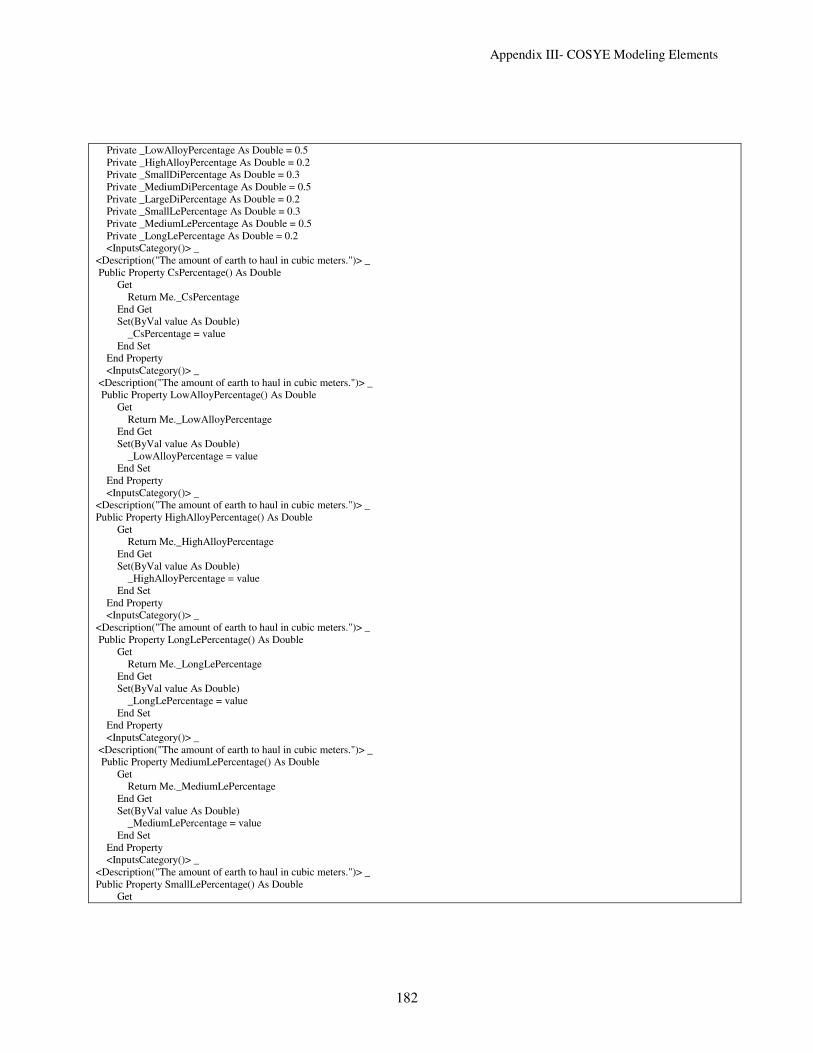
Appendix III- COSYE Modeling Elements
182
Private _LowAlloyPercentage As Double = 0.5
Private _HighAlloyPercentage As Double = 0.2
Private _SmallDiPercentage As Double = 0.3
Private _MediumDiPercentage As Double = 0.5
Private _LargeDiPercentage As Double = 0.2
Private _SmallLePercentage As Double = 0.3
Private _MediumLePercentage As Double = 0.5
Private _LongLePercentage As Double = 0.2
<InputsCategory()> _
<Description("The amount of earth to haul in cubic meters.")> _
Public Property CsPercentage() As Double
Get
Return Me._CsPercentage
End Get
Set(ByVal value As Double)
_CsPercentage = value
End Set
End Property
<InputsCategory()> _
<Description("The amount of earth to haul in cubic meters.")> _
Public Property LowAlloyPercentage() As Double
Get
Return Me._LowAlloyPercentage
End Get
Set(ByVal value As Double)
_LowAlloyPercentage = value
End Set
End Property
<InputsCategory()> _
<Description("The amount of earth to haul in cubic meters.")> _
Public Property HighAlloyPercentage() As Double
Get
Return Me._HighAlloyPercentage
End Get
Set(ByVal value As Double)
_HighAlloyPercentage = value
End Set
End Property
<InputsCategory()> _
<Description("The amount of earth to haul in cubic meters.")> _
Public Property LongLePercentage() As Double
Get
Return Me._LongLePercentage
End Get
Set(ByVal value As Double)
_LongLePercentage = value
End Set
End Property
<InputsCategory()> _
<Description("The amount of earth to haul in cubic meters.")> _
Public Property MediumLePercentage() As Double
Get
Return Me._MediumLePercentage
End Get
Set(ByVal value As Double)
_MediumLePercentage = value
End Set
End Property
<InputsCategory()> _
<Description("The amount of earth to haul in cubic meters.")> _
Public Property SmallLePercentage() As Double
Get

Appendix III- COSYE Modeling Elements
183
Return Me._SmallLePercentage
End Get
Set(ByVal value As Double)
_SmallLePercentage = value
End Set
End Property
<InputsCategory()> _
<Description("The amount of earth to haul in cubic meters.")> _
Public Property LargeDiPercentage() As Double
Get
Return Me._LargeDiPercentage
End Get
Set(ByVal value As Double)
_LargeDiPercentage = value
End Set
End Property
<InputsCategory()> _
<Description("The amount of earth to haul in cubic meters.")> _
Public Property MediumDiPercentage() As Double
Get
Return Me._MediumDiPercentage
End Get
Set(ByVal value As Double)
_MediumDiPercentage = value
End Set
End Property
<InputsCategory()> _
<Description("The amount of earth to haul in cubic meters.")> _
Public Property SmallDiPercentage() As Double
Get
Return Me._SmallDiPercentage
End Get
Set(ByVal value As Double)
_SmallDiPercentage = value
End Set
End Property
' <InputsCategory()> _
'<Description("The amount of earth to haul in cubic meters.")> _
'Public Property SpoolNoComponent() As Integer
' Get
' Return Me._SpoolNoComponent
' End Get
' Set(ByVal value As Integer)
' _SpoolNoComponent = Math.Max(0, value)
' End Set
' End Property
'Private AmountLoadedValue As Double = 100
' <InputsCategory()> _
'<Description("The amount of earth to haul in cubic meters.")> _
' Public Property NoSpool() As Integer
' Get
' Return Me._NoSpool
' End Get
' Set(ByVal value As Integer)
' _NoSpool = value
' End Set
' End Property
Protected Overrides Sub TransferIn(ByVal entity As ProxyEntity, ByVal point As Simphony.Modeling.InputPoint)
'MyBase.TransferIn(entity, point)
NoModulesIn += 1
Dim theClass = rtiAmb.GetObjectClassHandle("Product.Module")
Dim theModuleName = rtiAmb.GetAttributeHandle(theClass, "Name")

Appendix III- COSYE Modeling Elements
184
'entity.Instance
'Dim theModuleInstanceHandler = rtiAmb.GetObjectInstanceHandle(entity)
Dim theModuleTotalNumberofSpools = rtiAmb.GetAttributeHandle(theClass, "TotalNumberofSpool")
Dim ModulePriority = rtiAmb.GetAttributeHandle(theClass, "Priority")
Me.FirstOutputPoint.TransferOut(entity)
Trace.WriteLine("Module " & entity.Values(theModuleName) & entity.Values(theModuleTotalNumberofSpools))
Dim NoSpool = (entity.Values(theModuleTotalNumberofSpools))
Trace.WriteLine("NSpool " & NoSpool)
For I As Integer = 1 To NoSpool
Dim Spool As New SpoolEntity
NoSpoolOut += 1
Spool.ModuleName = entity.Values(theModuleName)
Spool.Priority = entity.Values(ModulePriority)
'Spool.ModuleName = entity.
Spool.ModuleID = NoModulesIn
Spool.ModuleHandle = entity.Instance
Spool.SpoolID = NoSpoolOut
Spool.NumberofComponents = SpoolNoComponent
Dim l1 As Double = Rnd()
If l1 <= LargeDiPercentage Then
Spool.DiameterSize = SpoolSize.Large
ElseIf LargeDiPercentage < l1 And l1 <= (LargeDiPercentage + MediumDiPercentage) Then
Spool.DiameterSize = SpoolSize.Intermediate
Else
Spool.DiameterSize = SpoolSize.Small
End If
Dim l2 As Double = Rnd()
If l2 <= LongLePercentage Then
Spool.Length = SpoolLength.Long
ElseIf LongLePercentage < l2 And l2 <= (LongLePercentage + MediumLePercentage) Then
Spool.Length = SpoolLength.Medium
Else
Spool.Length = SpoolLength.Small
End If
Dim l3 As Double = Rnd()
If l3 <= LongLePercentage Then
Spool.Material = SpoolMaterial.CarbonSteel
ElseIf LongLePercentage < l3 And l3 <= (LongLePercentage + MediumLePercentage) Then
Spool.Material = SpoolMaterial.LowAlloySteel
Else
Spool.Material = SpoolMaterial.HighAlloySteel
End If
Me.SecondOutputPoint.TransferOut(Spool)
Trace.WriteLine("SpoolID " & Spool.SpoolID & " DiameterSize " & Spool.DiameterSize.ToString) ' " ModuleName " &
Spool.ModuleName & "ModuleID " & Spool.ModuleID & "ModuleHandle" & Spool.ModuleHandle.ToString)

Appendix III- COSYE Modeling Elements
185
Next
End Sub
Public Overrides Sub Paint(ByVal graphics As System.Drawing.Graphics, ByVal bounds As System.Drawing.RectangleF)
MyBase.Paint(graphics, bounds)
graphics.DrawImage(My.Resources.CreateModuls.ToBitmap(), bounds)
End Sub
Protected Overrides Sub InitializeRun(ByVal runIndex As Integer)
MyBase.InitializeRun(runIndex)
Me.rtiAmb = Me.GetService(Of IRTIambassador)()
End Sub
End Class
Element: Create Spool Components Properties
Code: Imports System.Drawing
Public Class CreateSpoolComponents1
Inherits OutputElement(Of ComponentEntity)
Private _NoModule As Integer = 2
Private _NoofSpoolperModule As Integer = 10
Private _SpoolNoComponent As Integer = 3
Private _ComponentNoPipe As Integer = 2
Private _SmallPercentage As Double = 0.3
Private _MediumPercentage As Double = 0.5

Appendix III- COSYE Modeling Elements
186
Private _LargePercentage As Double = 0.2
Private _SmallDI As Double = 5
Private _MediumDI As Double = 10
Private _LargeDI As Double = 20
Private _TotalDI As Double
<OutputsCategory()> _
<Description("Total amount of Diameter Inch")> _
Public Property TotalDI() As Double
Get
Return Me._TotalDI
End Get
Private Set(ByVal value As Double)
Me._TotalDI = value
End Set
End Property
<InputsCategory()> _
<Description("Number of Pipes in each Component")> _
Public Property ComponentNoPipe() As Double
Get
Return Me._ComponentNoPipe
End Get
Set(ByVal value As Double)
_ComponentNoPipe = value
End Set
End Property
<InputsCategory()> _
<Description("Number of Spools in each Module")> _
Public Property NoofSpoolperModule() As Double
Get
Return Me._NoofSpoolperModule
End Get
Set(ByVal value As Double)
_NoofSpoolperModule = value
End Set
End Property
<InputsCategory()> _
<Description("Value of Large DI")> _
Public Property LargeDI() As Double
Get
Return Me._LargeDI
End Get
Set(ByVal value As Double)
_LargeDI = value
End Set
End Property
<InputsCategory()> _
<Description("Value of Medium DI")> _
Public Property MediumDI() As Double
Get
Return Me._MediumDI
End Get
Set(ByVal value As Double)
_MediumDI = value
End Set
End Property
<InputsCategory()> _
<Description("Value of Small DI")> _
Public Property SmallDI() As Double
Get
Return Me._SmallDI
End Get
Set(ByVal value As Double)

Appendix III- COSYE Modeling Elements
187
_SmallDI = value
End Set
End Property
<InputsCategory()> _
<Description("Percentage of Large DI")> _
Public Property LargePercentage() As Double
Get
Return Me._LargePercentage
End Get
Set(ByVal value As Double)
_LargePercentage = value
End Set
End Property
<InputsCategory()> _
<Description("Percentage of Medium DI")> _
Public Property MediumPercentage() As Double
Get
Return Me._MediumPercentage
End Get
Set(ByVal value As Double)
_MediumPercentage = value
End Set
End Property
<InputsCategory()> _
<Description("Percentage of Small DI")> _
Public Property SmallPercentage() As Double
Get
Return Me._SmallPercentage
End Get
Set(ByVal value As Double)
_SmallPercentage = value
End Set
End Property
<InputsCategory()> _
<Description("Related Module No")> _
Public Property NoModule() As Integer
Get
Return Me._NoModule
End Get
Set(ByVal value As Integer)
_NoModule = Math.Max(0, value)
End Set
End Property
<InputsCategory()> _
<Description("Number of Components for each Spool")> _
Public Property SpoolNoComponent() As Integer
Get
Return Me._SpoolNoComponent
End Get
Set(ByVal value As Integer)
_SpoolNoComponent = Math.Max(0, value)
End Set
End Property
Protected Overrides Sub InitializeRun(ByVal runIndex As Integer)
MyBase.InitializeRun(runIndex)
For i = 1 To NoModule
Dim TotalWorkUnit As Double
For k = 1 To NoofSpoolperModule
For j = 1 To SpoolNoComponent

Appendix III- COSYE Modeling Elements
188
Dim MyEntity As New ComponentEntity
Dim WorkUnit As Double
MyEntity.ModuleID = i
MyEntity.SpoolID = k + (i - 1) * (NoofSpoolperModule)
MyEntity.ComponentID = j
MyEntity.DI = 0
MyEntity.NoPipesforComponent = ComponentNoPipe
MyEntity.NumberofComponents = SpoolNoComponent
MyEntity.AvailableNoComponents = 0
Dim l As Double = Rnd()
'Trace.WriteLine("l " & l)
If l <= LargePercentage Then
MyEntity.Diameter = "Large"
WorkUnit = LargeDI
ElseIf LargePercentage < l And l <= (LargePercentage + MediumPercentage) Then
MyEntity.Diameter = "Medium"
WorkUnit = MediumDI
Else
MyEntity.Diameter = "Small"
WorkUnit = SmallDI
End If
For m = 1 To MyEntity.NoPipesforComponent
MyEntity.DI += WorkUnit
Next
Me.OutputPoint.TransferOut(MyEntity)
Trace.WriteLine(MyEntity.SpoolID)
TotalWorkUnit = MyEntity.DI
_TotalDI += TotalWorkUnit
Next
Next
Next
End Sub
End Class

Appendix III- COSYE Modeling Elements
189
Element: Fab Station Properties
Code: Imports System.Drawing
Imports Simphony.Simulation
Imports Cosye.Modeling
Imports Simphony
Imports Simphony.Mathematics
Imports System.IO
Imports System.Xml
Imports System.Drawing.Imaging
Public Class FabStation
Inherits FlowElement(Of ComponentEntity)
Private _NumberofStations As Integer = 1
Private _NumberofWorkers As Integer = 1
Private _NeededWorkerforStation As Integer = 1
Private _WorkerType As String = "Cutter"
Private _StationType As String = "Cutting Station"
Private Station As New Resource(StationType, NumberofStations)
Private Worker As New Resource(WorkerType, NumberofWorkers)
Private ComponentsQueue As New WaitingFile("ComponentQueue")
Private _AmountProcced As New Double
Private _Troughput As Double = 10

Appendix III- COSYE Modeling Elements
190
Private _ComponentState As String = "Cut"
Private ReadOnly CycleTimeValue As New NumericStatistic("CycleTime", False)
<InputsCategory()> _
<Description("")> _
Public Property Troughput() As Integer
Get
Return Me._Troughput
End Get
Set(ByVal value As Integer)
_Troughput = value
End Set
End Property
<InputsCategory()> _
<Description("")> _
Public Property NeededWorkerforStation() As Integer
Get
Return Me._NeededWorkerforStation
End Get
Set(ByVal value As Integer)
_NeededWorkerforStation = value
End Set
End Property
<InputsCategory()> _
<Description("")> _
Public Property WorkerType() As String
Get
Return Me._WorkerType
End Get
Set(ByVal value As String)
_WorkerType = value
End Set
End Property
<InputsCategory()> _
<Description("")> _
Public Property StationType() As String
Get
Return Me._StationType
End Get
Set(ByVal value As String)
_StationType = value
End Set
End Property
<InputsCategory()> _
<Description("")> _
Public Property NumberofWorkers() As Integer
Get
Return Me._NumberofWorkers
End Get
Set(ByVal value As Integer)
_NumberofWorkers = value
End Set
End Property
<InputsCategory()> _
<Description("")> _
Public Property NumberofStations() As Integer
Get
Return Me._NumberofStations
End Get
Set(ByVal value As Integer)
_NumberofStations = value
End Set
End Property

Appendix III- COSYE Modeling Elements
191
<InputsCategory()> _
<Description("")> _
Public Property ComponentState() As String
Get
Return Me._ComponentState
End Get
Set(ByVal value As String)
_ComponentState = value
End Set
End Property
<OutputsCategory()> _
<Description("")> _
Public Property AmountProcced() As Double
Get
Return Me._AmountProcced
End Get
Private Set(ByVal value As Double)
Me._AmountProcced = value
End Set
End Property
<StatisticsCategory()> _
<Description("")> _
Public ReadOnly Property WorkerUtilization() As NumericStatistic
Get
Return Me.Worker.Utilization
End Get
End Property
<StatisticsCategory()> _
<Description("")> _
Public ReadOnly Property StationUtilization() As NumericStatistic
Get
Return Me.Station.Utilization
End Get
End Property
<StatisticsCategory()> _
<Description("")> _
Public ReadOnly Property FileLength() As NumericStatistic
Get
Return Me.ComponentsQueue.FileLength
End Get
End Property
<StatisticsCategory()> _
<Description("")> _
Public ReadOnly Property WaitingTime() As NumericStatistic
Get
Return Me.ComponentsQueue.WaitingTime
End Get
End Property
<StatisticsCategory()> _
<Description("")> _
Public ReadOnly Property CycleTime() As NumericStatistic
Get
Return Me.CycleTimeValue
End Get
End Property
Public Sub New()
Me.AddResource(Me.Station) 'Adding a resource to the constructor
Me.AddResource(Me.Worker)
Me.AddWaitingFile(Me.ComponentsQueue) 'Adding a waiting file to the constructor
Me.Station.WaitingFiles.Add(Me.ComponentsQueue) 'Linking up the Resource and Waiting File
Me.Worker.WaitingFiles.Add(Me.ComponentsQueue)
Me.AddStatistic(Me.CycleTime)

Appendix III- COSYE Modeling Elements
192
'Me.Size = My.Resources.Fabrication.Size
End Sub
Public Overrides Sub Paint(ByVal graphics As System.Drawing.Graphics, ByVal bounds As System.Drawing.RectangleF)
Dim myBrush As New SolidBrush(Color.DarkSlateBlue)
Dim f As Font = New Font("Arial", 8, FontStyle.Regular)
graphics.DrawString(Me.StationType.ToString, f, myBrush, bounds.Left - 15, bounds.Top + 60)
MyBase.Paint(graphics, bounds)
graphics.DrawImage(My.Resources.Fabrication.ToBitmap, bounds)
End Sub
Protected Overrides Sub InitializeRun(ByVal runIndex As Integer)
MyBase.InitializeRun(runIndex)
Me.AmountProcced = 0
End Sub
Protected Overrides Sub TransferIn(ByVal entity As ComponentEntity, ByVal point As Simphony.Modeling.InputPoint)
'MyBase.TransferIn(entity, point)
Dim Handler = New Action(Of ComponentEntity)(AddressOf Me.StartFabProcess)
Dim MyRequirements As New MultipleResourceRequirement()
MyRequirements.Add(Me.Station, 1)
MyRequirements.Add(Me.Worker, 1)
Me.Engine.RequestResource(entity, MyRequirements, Handler, Me.ComponentsQueue, entity.Priority)
Trace.WriteLine("Queue " & Me.ComponentsQueue.FileLength.ToString & "WaitingTime " & Me.ComponentsQueue.WaitingTime.ToString)
'Me.GetType.GetElementType.
End Sub
Private Sub StartFabProcess(ByVal Entity As ComponentEntity)
Dim Handler = New Action(Of ComponentEntity)(AddressOf Me.FinishFabProcess)
Me.Scenario.Floats(1) = Me.Engine.TimeNow
Dim duration = Entity.TotalWork * _Troughput
'Trace.WriteLine("Vasat" & Entity.Id)
Me.Engine.ScheduleEvent(Entity, Handler, duration)
Trace.WriteLine("TIME " & Me.Scenario.Floats(1))
End Sub
Private Sub FinishFabProcess(ByVal Entity As ComponentEntity)
Entity.State = ComponentState
Me.AmountProcced += Entity.TotalWork
'Trace.WriteLine("Bye" & Entity.Id)
Me.Engine.ReleaseResource(Entity, Me.Station, 1)
Me.Engine.ReleaseResource(Entity, Me.Worker, 1)
Me.OutputPoint.TransferOut(Entity)
Me.CycleTime.Collect(Me.Engine.TimeNow - Me.Scenario.Floats(1))
End Sub
End Class
Element: Worker
Code: Imports System.Drawing
Imports Simphony.Simulation
Imports Cosye.Modeling
Imports Simphony
Imports Simphony.Mathematics
Imports System.IO
Imports System.Xml

Appendix III- COSYE Modeling Elements
193
Imports System.Drawing.Imaging
Public Class Worker
Inherits ElementBase
'Private _WorkerType As String = "Cutter"
Private _NumberofWorkers As Integer = 4
'Private Worker As New Resource(WorkerType, NumberofWorkers)
Private ComponentsQueue As New WaitingFile("ComponentQueue")
Private ReadOnly _Worker As New Resource("Worker", 4)
Friend ReadOnly Property Worker() As Resource
Get
Return Me._Worker
End Get
End Property
<OutputsCategory()> _
<Description("")> _
Public ReadOnly Property AvailableWorkers() As Integer
Get
Return Me.Worker.Available
End Get
End Property
<OutputsCategory()> _
<Description("")> _
Public ReadOnly Property InUseWorkers() As Integer
Get
Return Me.Worker.InUse
End Get
End Property
<InputsCategory()> _
<Description("")> _
Public Property NumberofWorkers() As Integer
Get
Return Me._NumberofWorkers
End Get
Set(ByVal value As Integer)
_NumberofWorkers = value
End Set
End Property
<StatisticsCategory()> _
<Description("")> _
Public ReadOnly Property WorkerUtilization() As NumericStatistic
Get
Return Me.Worker.Utilization
End Get
End Property
<StatisticsCategory()> _
<Description("")> _
Public ReadOnly Property FileLength() As NumericStatistic
Get
Return Me.ComponentsQueue.FileLength
End Get
End Property
<StatisticsCategory()> _
<Description("")> _
Public ReadOnly Property WaitingTime() As NumericStatistic
Get
Return Me.ComponentsQueue.WaitingTime
End Get
End Property
Public Sub New()
Me.AddResource(Me.Worker)
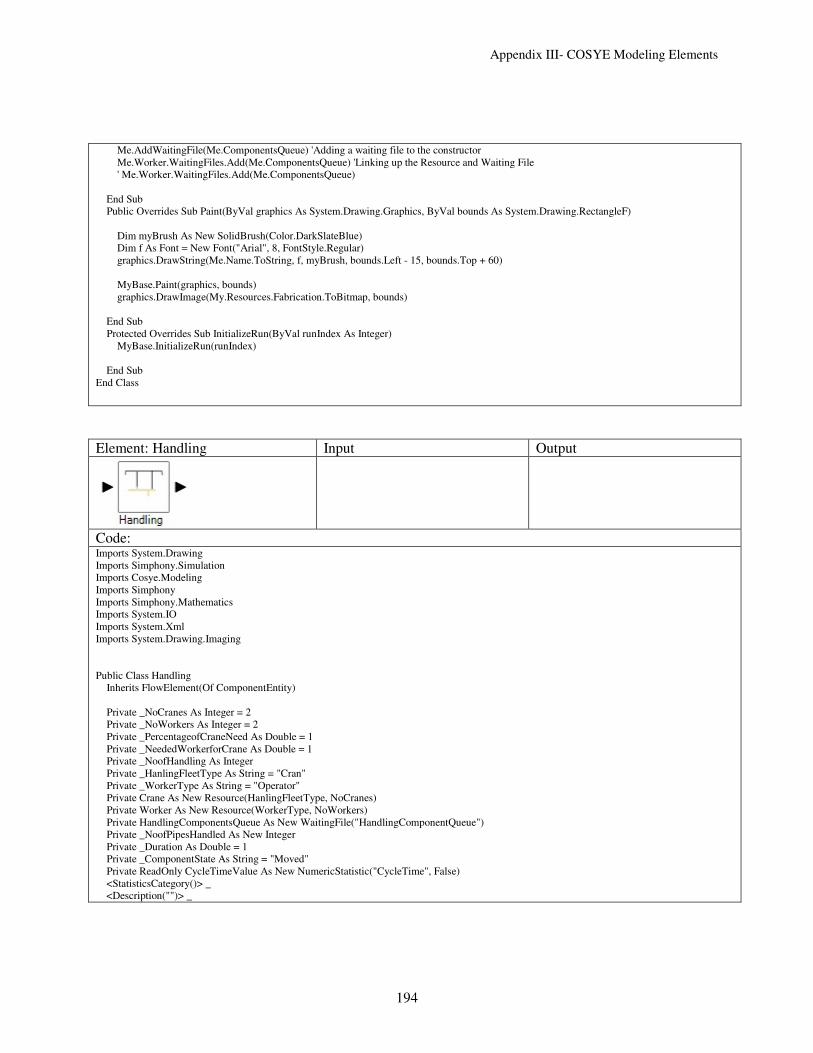
Appendix III- COSYE Modeling Elements
194
Me.AddWaitingFile(Me.ComponentsQueue) 'Adding a waiting file to the constructor
Me.Worker.WaitingFiles.Add(Me.ComponentsQueue) 'Linking up the Resource and Waiting File
' Me.Worker.WaitingFiles.Add(Me.ComponentsQueue)
End Sub
Public Overrides Sub Paint(ByVal graphics As System.Drawing.Graphics, ByVal bounds As System.Drawing.RectangleF)
Dim myBrush As New SolidBrush(Color.DarkSlateBlue)
Dim f As Font = New Font("Arial", 8, FontStyle.Regular)
graphics.DrawString(Me.Name.ToString, f, myBrush, bounds.Left - 15, bounds.Top + 60)
MyBase.Paint(graphics, bounds)
graphics.DrawImage(My.Resources.Fabrication.ToBitmap, bounds)
End Sub
Protected Overrides Sub InitializeRun(ByVal runIndex As Integer)
MyBase.InitializeRun(runIndex)
End Sub
End Class
Element: Handling Input Output
Code: Imports System.Drawing
Imports Simphony.Simulation
Imports Cosye.Modeling
Imports Simphony
Imports Simphony.Mathematics
Imports System.IO
Imports System.Xml
Imports System.Drawing.Imaging
Public Class Handling
Inherits FlowElement(Of ComponentEntity)
Private _NoCranes As Integer = 2
Private _NoWorkers As Integer = 2
Private _PercentageofCraneNeed As Double = 1
Private _NeededWorkerforCrane As Double = 1
Private _NoofHandling As Integer
Private _HanlingFleetType As String = "Cran"
Private _WorkerType As String = "Operator"
Private Crane As New Resource(HanlingFleetType, NoCranes)
Private Worker As New Resource(WorkerType, NoWorkers)
Private HandlingComponentsQueue As New WaitingFile("HandlingComponentQueue")
Private _NoofPipesHandled As New Integer
Private _Duration As Double = 1
Private _ComponentState As String = "Moved"
Private ReadOnly CycleTimeValue As New NumericStatistic("CycleTime", False)
<StatisticsCategory()> _
<Description("")> _

Appendix III- COSYE Modeling Elements
195
Public ReadOnly Property WorkerUtilization() As NumericStatistic
Get
Return Me.Worker.Utilization
End Get
End Property
<StatisticsCategory()> _
<Description("")> _
Public ReadOnly Property CraneUtilization() As NumericStatistic
Get
Return Me.Crane.Utilization
End Get
End Property
<StatisticsCategory()> _
<Description("")> _
Public ReadOnly Property FileLength() As NumericStatistic
Get
Return Me.HandlingComponentsQueue.FileLength
End Get
End Property
<StatisticsCategory()> _
<Description("")> _
Public ReadOnly Property CycleTime() As NumericStatistic
Get
Return Me.CycleTimeValue
End Get
End Property
<InputsCategory()> _
<Description("")> _
Public Property PercentageofCraneNeed() As Integer
Get
Return Me._PercentageofCraneNeed
End Get
Set(ByVal value As Integer)
_PercentageofCraneNeed = value
End Set
End Property
<InputsCategory()> _
<Description("")> _
Public Property NoCranes() As Integer
Get
Return Me._NoCranes
End Get
Set(ByVal value As Integer)
_NoCranes = value
End Set
End Property
<InputsCategory()> _
<Description("")> _
Public Property NoWorkers() As Integer
Get
Return Me._NoWorkers
End Get
Set(ByVal value As Integer)
_NoWorkers = value
End Set
End Property
<InputsCategory()> _
<Description("")> _
Public Property WorkerType() As String
Get
Return Me._WorkerType
End Get

Appendix III- COSYE Modeling Elements
196
Set(ByVal value As String)
_WorkerType = value
End Set
End Property
<InputsCategory()> _
<Description("")> _
Public Property HanlingFleetType() As String
Get
Return Me._HanlingFleetType
End Get
Set(ByVal value As String)
_HanlingFleetType = value
End Set
End Property
<OutputsCategory()> _
<Description("")> _
Public Property NoofPipesHandled() As Integer
Get
Return Me._NoofPipesHandled
End Get
Private Set(ByVal value As Integer)
Me._NoofPipesHandled = value
End Set
End Property
Public Sub New()
Me.AddResource(Me.Crane) 'Adding a resource to the constructor
Me.AddResource(Me.Worker)
Me.AddStatistic(Me.CycleTime)
Me.AddWaitingFile(Me.HandlingComponentsQueue) 'Adding a waiting file to the constructor
Me.Crane.WaitingFiles.Add(Me.HandlingComponentsQueue) 'Linking up the Resource and Waiting File
End Sub
Protected Overrides Sub InitializeRun(ByVal runIndex As Integer)
MyBase.InitializeRun(runIndex)
Me.NoofPipesHandled = 0
End Sub
Public Overrides Sub Paint(ByVal graphics As System.Drawing.Graphics, ByVal bounds As System.Drawing.RectangleF)
MyBase.Paint(graphics, bounds)
graphics.DrawImage(My.Resources.Handling.ToBitmap(), bounds)
End Sub
Protected Overrides Sub TransferIn(ByVal entity As ComponentEntity, ByVal point As Simphony.Modeling.InputPoint)
'MyBase.TransferIn(entity, point)
Dim Handler = New Action(Of ComponentEntity)(AddressOf Me.StartHandling)
Dim l As Double = Rnd()
Dim MyRequirements As New MultipleResourceRequirement()
If l <= PercentageofCraneNeed Then
MyRequirements.Add(Me.Crane, 1)
MyRequirements.Add(Me.Worker, 1)
Else
MyRequirements.Add(Me.Crane, 1)
End If
Me.Engine.RequestResource(entity, MyRequirements, Handler, Me.HandlingComponentsQueue)
End Sub
Private Sub StartHandling(ByVal Entity As ComponentEntity)
Dim Handler = New Action(Of ComponentEntity)(AddressOf Me.FinishHandling)
Dim duration = Entity.NoPipesforComponent * _Duration
Me.Engine.ScheduleEvent(Entity, Handler, duration)
End Sub
Private Sub FinishHandling(ByVal Entity As ComponentEntity)

Appendix III- COSYE Modeling Elements
197
'Entity.State = ComponentState
Me.NoofPipesHandled += Entity.NoPipesforComponent
Me.Engine.ReleaseResource(Entity, Me.Crane, 1)
Me.Engine.ReleaseResource(Entity, Me.Worker, 1)
Me.OutputPoint.TransferOut(Entity)
End Sub
End Class
Element: Dispatch Properties
Code: Imports System.Drawing
Imports Simphony.Simulation
Imports Cosye.Modeling
Imports Simphony
Imports Simphony.Mathematics
Imports System.IO
Imports System.Xml
Imports System.Drawing.Imaging
Public Class Dispatch
Inherits DivergeElement(Of ComponentEntity)
Private OperatorValue As String = "True"
Private ComponentPeropertyValue As String = "DiameterSize"
Private PeropertyValue As String = "Small"
<InputsCategory()> _
<Description("")> _
Public Property [Operator]() As String
Get
Return Me.OperatorValue
End Get
Set(ByVal value As String)
OperatorValue = value
End Set
End Property
<InputsCategory()> _
<Description("")> _
Public Property ComponentPeroperty() As String

Appendix III- COSYE Modeling Elements
198
Get
Return Me.ComponentPeropertyValue
End Get
Set(ByVal value As String)
ComponentPeropertyValue = value
End Set
End Property
<InputsCategory()> _
<Description("")> _
Public Property Peroperty() As String
Get
Return Me.PeropertyValue
End Get
Set(ByVal value As String)
PeropertyValue = value
End Set
End Property
Protected Overrides Sub InitializeRun(ByVal runIndex As Integer)
MyBase.InitializeRun(runIndex)
End Sub
Public Overrides Sub Paint(ByVal graphics As System.Drawing.Graphics, ByVal bounds As System.Drawing.RectangleF)
Dim myBrush As New SolidBrush(Color.DarkSlateBlue)
Dim f As Font = New Font("Arial", 8, FontStyle.Regular)
graphics.DrawString(Me.Peroperty.ToString, f, myBrush, bounds.Left, bounds.Top + 60)
MyBase.Paint(graphics, bounds)
graphics.DrawImage(My.Resources.Dispatch, bounds)
End Sub
Protected Overrides Sub TransferIn(ByVal entity As ComponentEntity, ByVal point As Simphony.Modeling.InputPoint)
'MyBase.TransferIn(entity, point)
Select Case ComponentPeropertyValue
Case "DiameterSize" : If entity.DiameterSize.ToString = Peroperty Then
Me.FirstOutputPoint.TransferOut(entity)
Else
Me.SecondOutputPoint.TransferOut(entity)
End If
Case "Length" : If entity.Length.ToString = Peroperty Then
Me.FirstOutputPoint.TransferOut(entity)
Else
Me.SecondOutputPoint.TransferOut(entity)
End If
Case "Material" : If entity.Material.ToString = Peroperty Then
Me.FirstOutputPoint.TransferOut(entity)
Else
Me.SecondOutputPoint.TransferOut(entity)
End If
End Select
End Sub
End Class
Element: Assembler Input Output

Appendix III- COSYE Modeling Elements
199
Code: Imports System.Collections
Imports System
Imports System.Drawing
Imports System.Data
Public Class Assembler
Inherits FlowElement(Of ComponentEntity)
Private SpoolinfoTable As New DataTable()
Dim NSpoolSArrived As Integer = 0
Private Sub CreatSpoolinfoTable()
Dim myDataColumn As New DataColumn("SpoolID1", GetType(System.String))
SpoolinfoTable.Columns.Add(myDataColumn)
myDataColumn = New DataColumn("NoComponents1", GetType(System.Int32))
SpoolinfoTable.Columns.Add(myDataColumn)
myDataColumn = New DataColumn("FinishedNoComponents1", GetType(System.Int32)) 'enum type
SpoolinfoTable.Columns.Add(myDataColumn)
myDataColumn = New DataColumn("PositionDI1", GetType(System.String))
SpoolinfoTable.Columns.Add(myDataColumn)
SpoolinfoTable.AcceptChanges()
End Sub
Private Sub InitialzeSpoolinfoTable()
For i As Integer = 0 To 100
Dim myDataRow As DataRow
myDataRow = SpoolinfoTable.NewRow()
myDataRow("SpoolID1") = "0"
myDataRow("NoComponents1") = 0
myDataRow("FinishedNoComponents1") = 0
myDataRow("PositionDI1") = "0"
SpoolinfoTable.Rows.Add(myDataRow)
Next
End Sub
Public Sub New()
CreatSpoolinfoTable()
End Sub
Protected Overrides Sub InitializeRun(ByVal runIndex As Integer)
MyBase.InitializeRun(runIndex)
InitialzeSpoolinfoTable()
End Sub
Public Overrides Sub Paint(ByVal graphics As System.Drawing.Graphics, ByVal bounds As System.Drawing.RectangleF)
MyBase.Paint(graphics, bounds)
graphics.DrawImage(My.Resources.Assembler.ToBitmap(), bounds)
End Sub
Protected Overrides Sub TransferIn(ByVal entity As ComponentEntity, ByVal point As Simphony.Modeling.InputPoint)

Appendix III- COSYE Modeling Elements
200
Dim exsist As String = "NO"
For i As Integer = 0 To NSpoolSArrived - 1
If entity.SpoolID = SpoolinfoTable.Rows.Item(i)("SpoolID1") Then
exsist = "YES"
SpoolinfoTable.Rows.Item(i)("FinishedNoComponents1") += 1
Trace.WriteLine("EntityStayes" & entity.SpoolID)
If SpoolinfoTable.Rows.Item(i)("FinishedNoComponents1") = entity.NumberofComponents Then
Me.OutputPoint.TransferOut(entity)
Trace.WriteLine("EntityOut" & entity.SpoolID)
End If
End If
Next
If exsist = "NO" Then
SpoolinfoTable.Rows.Item(NSpoolSArrived)("SpoolID1") = entity.SpoolID
SpoolinfoTable.Rows.Item(NSpoolSArrived)("FinishedNoComponents1") += 1
NSpoolSArrived += 1
End If
End Sub
End Class
Element: Proxy Module Assembler Properties
Code: Imports System.Drawing
Imports Simphony.Simulation
Imports Cosye.Hla.Rti
Imports Cosye.Modeling
Imports Simphony
Imports Simphony.Mathematics
Public Class ProxyModuleAssembler
Inherits FlowElement(Of SpoolEntity)
Private ReadOnly spoolCount As New Dictionary(Of ObjectInstanceHandle, Integer)
Private rtiAmb As IRTIambassador
Private proxies As IProxyProvider
Private SpoolinfoTable As New DataTable()
Dim NModuleSArrived As Integer = 0
Protected Overrides Sub InitializeRun(ByVal runIndex As Integer)
MyBase.InitializeRun(runIndex)

Appendix III- COSYE Modeling Elements
201
'SpoolinfoTable.Clear()
'InitialzeModuleinfoTable()
Me.spoolCount.Clear()
Me.rtiAmb = Me.GetService(Of IRTIambassador)()
Me.proxies = Me.GetService(Of IProxyProvider)()
End Sub
Protected Overrides Sub TransferIn(ByVal entity As SpoolEntity, ByVal point As Simphony.Modeling.InputPoint)
'MyBase.TransferIn(entity, point)
Trace.WriteLine("Modulehandle:** " & entity.ModuleHandle.ToString)
Dim proxy = Me.proxies(entity.ModuleHandle)
Dim theClass = rtiAmb.GetKnownObjectClassHandle(entity.ModuleHandle)
Dim theModuleTotalNumberofSpools = rtiAmb.GetAttributeHandle(theClass, "TotalNumberofSpool")
Dim theModuleFinishedNumberofSpools = rtiAmb.GetAttributeHandle(theClass, "NumberofSpoolsFabricated")
Dim CompReadyTime = rtiAmb.GetAttributeHandle(theClass, "CompReadyTime")
If Me.spoolCount.ContainsKey(entity.ModuleHandle) Then
Me.spoolCount(entity.ModuleHandle) += 1
Else
Me.spoolCount(entity.ModuleHandle) = 1
End If
rtiAmb.AttributeOwnershipAcquisition(entity.ModuleHandle, New AttributeHandle() {theModuleFinishedNumberofSpools}, Nothing)
rtiAmb.AttributeOwnershipAcquisition(entity.ModuleHandle, New AttributeHandle() {CompReadyTime}, Nothing)
Dim theValues As New AttributeHandleValueMap()
Dim lookahead = CType(Me.Scenario, CosyeScenario).Lookahead
theValues.Add(theModuleFinishedNumberofSpools, Me.spoolCount(entity.ModuleHandle))
theValues.Add(CompReadyTime, Me.Engine.TimeNow)
rtiAmb.UpdateAttributeValues(entity.ModuleHandle, theValues, Nothing, Me.Engine.TimeNow + lookahead)
rtiAmb.UnconditionalAttributeOwnershipDivestiture(entity.ModuleHandle, New AttributeHandle() {theModuleFinishedNumberofSpools})
rtiAmb.UnconditionalAttributeOwnershipDivestiture(entity.ModuleHandle, New AttributeHandle() {CompReadyTime})
If Me.spoolCount(entity.ModuleHandle) = proxy.Values(theModuleTotalNumberofSpools) Then
Dim newEntity = New ProxyEntity(proxy)
Dim handler = New Action(Of ProxyEntity)(AddressOf TransferOut)
Me.Engine.ScheduleEvent(newEntity, handler, lookahead)
Trace.WriteLine("Lookahead" & lookahead)
End If
End Sub
Private Sub TransferOut(ByVal entity As ProxyEntity)
Me.OutputPoint.TransferOut(entity)
End Sub
End Class
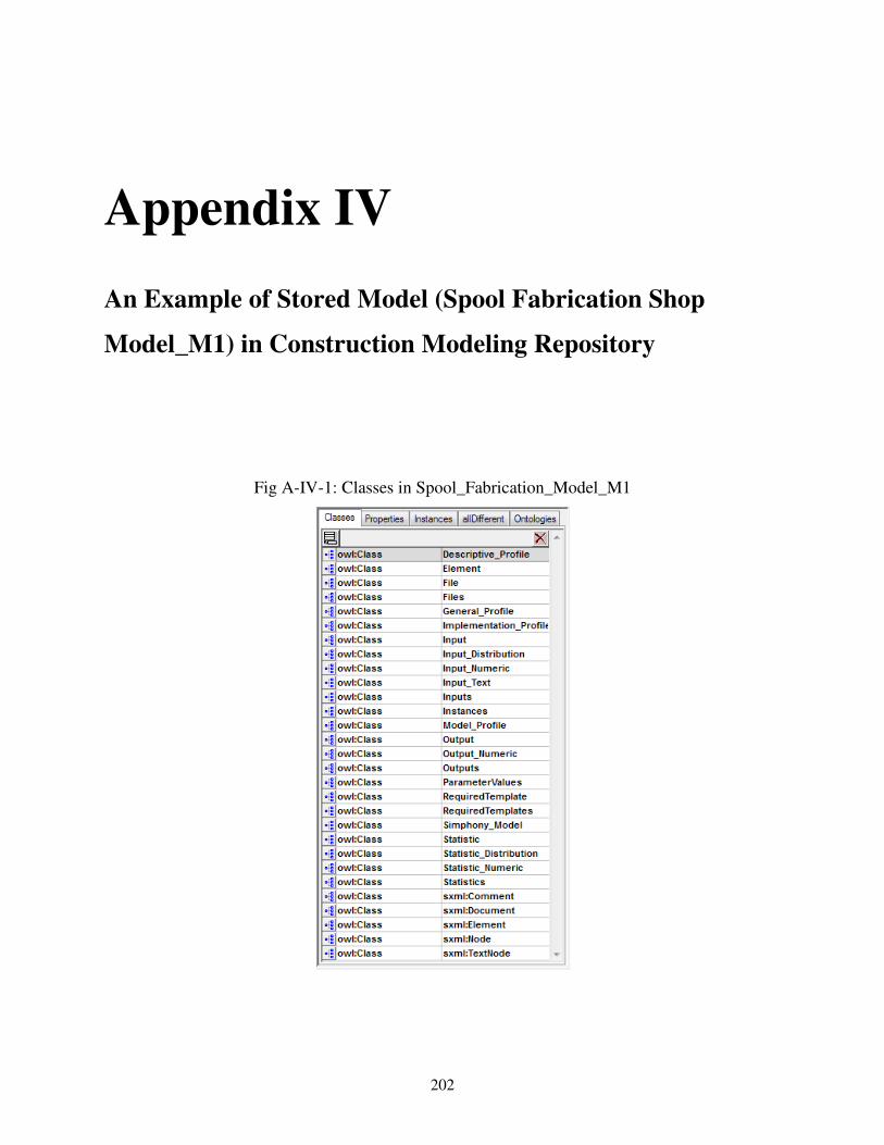
202
Appendix IV
An Example of Stored Model (Spool Fabrication Shop
Model_M1) in Construction Modeling Repository
Fig A-IV-1: Classes in Spool_Fabrication_Model_M1

Appendix IV – Spool_Fabrication_Model
203
Fig A-IV-2: Properties in Spool_Fabrication_Model_M1

Appendix IV – Spool_Fabrication_Model
204
Fig A-IV-2: Instances in Spool_Fabrication_Model_M1

Appendix IV – Spool_Fabrication_Model
205
Fig A-IV-2: Ontologies in Spool_Fabrication_Model_M1
Spool_Fabrication_Model_M1 RDF Code (just first and last page):
<?xml version="1.0"?>
<rdf:RDF
xmlns:sxml="http://topbraid.org/sxml#"
xmlns:rdf="http://www.w3.org/1999/02/22-rdf-syntax-ns#"
xmlns:owl="http://www.w3.org/2002/07/owl#"
xmlns:xsd="http://www.w3.org/2001/XMLSchema#"
xmlns:composite="http://www.topbraid.org/2007/05/composite.owl#"
xmlns="file:///evn.topbraidlive.org/Mixed-Repository/FabshopModel-M1.xml#"
xmlns:rdfs="http://www.w3.org/2000/01/rdf-schema#"
xml:base="file:///evn.topbraidlive.org/Mixed-Repository/FabshopModel-M1.xml">
<owl:Ontology rdf:about="">
<owl:imports rdf:resource="http://topbraid.org/sxml"/>
</owl:Ontology>
<owl:Class rdf:ID="Input_Text">
<rdfs:label>Input_Text</rdfs:label>
<sxml:element>Input_Text</sxml:element>
</owl:Class>
<owl:Class rdf:ID="Simphony_Model">
<rdfs:label>Simphony_Model</rdfs:label>
<sxml:element>Simphony_Model</sxml:element>
</owl:Class>
<owl:Class rdf:ID="ParameterValues">
<rdfs:label>ParameterValues</rdfs:label>
<sxml:element>ParameterValues</sxml:element>
</owl:Class>
<owl:Class rdf:ID="Element">
<rdfs:label>Element</rdfs:label>
<sxml:element>Element</sxml:element>
</owl:Class>
<owl:Class rdf:ID="Files">
<rdfs:label>Files</rdfs:label>

Appendix IV – Spool_Fabrication_Model
206
<sxml:element>Files</sxml:element>
</owl:Class>
<owl:Class rdf:ID="Input_Distribution">
<rdfs:label>Input_Distribution</rdfs:label>
<sxml:element>Input_Distribution</sxml:element>
</owl:Class>
<owl:Class rdf:ID="RequiredTemplates">
<rdfs:label>RequiredTemplates</rdfs:label>
<sxml:element>RequiredTemplates</sxml:element>
</owl:Class>
<owl:Class rdf:ID="Statistic_Numeric">
<rdfs:label>Statistic_Numeric</rdfs:label>
<sxml:element>Statistic_Numeric</sxml:element>
</owl:Class>
<owl:Class rdf:ID="Implementation_Profile">
<rdfs:label>Implementation_Profile</rdfs:label>
<sxml:element>Implementation_Profile</sxml:element>
</owl:Class>
<owl:Class rdf:ID="Input_Numeric">
<rdfs:label>Input_Numeric</rdfs:label>
<sxml:element>Input_Numeric</sxml:element>
</owl:Class>
<owl:Class rdf:ID="Model_Profile">
<rdfs:label rdf:datatype="http://www.w3.org/2001/XMLSchema#string"
>Model_Profile</rdfs:label>
<sxml:element rdf:datatype="http://www.w3.org/2001/XMLSchema#string"
>Model_Profile</sxml:element>
</owl:Class>
<owl:Class rdf:ID="Output_Numeric">
<rdfs:label>Output_Numeric</rdfs:label>
<sxml:element>Output_Numeric</sxml:element>
</owl:Class>
<owl:Class rdf:ID="Input">
<rdfs:label>Input</rdfs:label>
<sxml:element>Input</sxml:element>
</owl:Class>
.
.
.
<RequiredTemplate rdf:ID="r-0-1-0-0">
<composite:index rdf:datatype="http://www.w3.org/2001/XMLSchema#int"
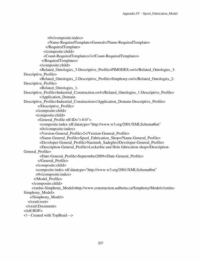
Appendix IV – Spool_Fabrication_Model
207
>0</composite:index>
<Name-RequiredTemplate>General</Name-RequiredTemplate>
</RequiredTemplate>
</composite:child>
<Count-RequiredTemplates>2</Count-RequiredTemplates>
</RequiredTemplates>
</composite:child>
<Related_Ontologies_3-Descriptive_Profile>PIMODES.owl</Related_Ontologies_3-
Descriptive_Profile>
<Related_Ontologies_2-Descriptive_Profile>Simphony.owl</Related_Ontologies_2-
Descriptive_Profile>
<Related_Ontologies_1-
Descriptive_Profile>Industrial_Construction.owl</Related_Ontologies_1-Descriptive_Profile>
<Application_Domain-
Descriptive_Profile>Industrial_Construction</Application_Domain-Descriptive_Profile>
</Descriptive_Profile>
</composite:child>
<composite:child>
<General_Profile rdf:ID="r-0-0">
<composite:index rdf:datatype="http://www.w3.org/2001/XMLSchema#int"
>0</composite:index>
<Version-General_Profile>2</Version-General_Profile>
<Name-General_Profile>Spool_Fabrication_Shop</Name-General_Profile>
<Developer-General_Profile>Naeimeh_Sadeghi</Developer-General_Profile>
<Description-General_Profile>Lockerbie and Hole fabrication shop</Description-
General_Profile>
<Date-General_Profile>Septermber2009</Date-General_Profile>
</General_Profile>
</composite:child>
<composite:index rdf:datatype="http://www.w3.org/2001/XMLSchema#int"
>0</composite:index>
</Model_Profile>
</composite:child>
<xmlns-Simphony_Model>http://www.construction.ualberta.ca/Simphony/Model</xmlns-
Simphony_Model>
</Simphony_Model>
</sxml:root>
</sxml:Document>
</rdf:RDF>
<!-- Created with TopBraid -->

208
Appendix V
Construction Modeling Repository SPARQL
Queries
Table A-III-1: Construction Modeling Repository SPARQL queries syntax and results
displayed in TBC # Query Result
Q1
Q2

Appendix V - Repository Queries
209
Q3
Q4
Q5

Appendix V - Repository Queries
210
Q6
Q7
Q8 WHERE {
{
?Element a TunM:Element .
?Element TunM:Element-Element ?ElementI .
?Element TunM:Element_Name-Element ?Element_Name .
FILTER regex(?Element_Name, "Shift") .
?Element TunM:Template-Element ?Template .
}
UNION
{
?Element TunM:Element-Element ?ElementI . ?Element TunM:Element_Name-Element ?Element_Name .
?Element TunM:Template-Element ?Template .
?Element composite:child ?Inputs .
?Inputs composite:child ?Input .
?Input TunM:Name-Input ?InputName .
FILTER regex(?InputName, "Shift") .
}
UNION
{
?Element TunM:Element-Element ?ElementI .
?Element TunM:Element_Name-Element ?Element_Name . ?Element TunM:Template-Element ?Template .
?Element composite:child ?Ouputs .
?Ouputs composite:child ?Output .
?Output TunM:Name-Output ?OutputName .
FILTER regex(?OutputName, "Shift") .
}
UNION
{
?Element a FabM1:Element .
?Element FabM1:Element-Element ?ElementI .
?Element FabM1:Element_Name-Element ?Element_Name . FILTER regex(?Element_Name, "Shift") .
?Element FabM1:Template-Element ?Template .
}
UNION
{
?Element FabM1:Element-Element ?ElementI .
?Element FabM1:Element_Name-Element ?Element_Name .
?Element FabM1:Template-Element ?Template .
?Element composite:child ?Inputs .
?Inputs composite:child ?Input .
?Input FabM1:Name-Input ?InputName .
FILTER regex(?InputName, "Shift") . }
UNION
{
?Element FabM1:Element-Element ?ElementI .
?Element FabM1:Element_Name-Element ?Element_Name .
?Element FabM1:Template-Element ?Template .
?Element composite:child ?Ouputs .

Appendix V - Repository Queries
211
?Ouputs composite:child ?Output .
?Output FabM1:Name-Output ?OutputName .
FILTER regex(?OutputName, "Shift") .
} .
}
Q9
Q10

Appendix V - Repository Queries
212
Q10
Q1

Appendix V - Repository Queries
213
Q2


![Measuring the Reusability of Software Components using ... · the reusability of source code components using static analysis metrics [10, 11, 33], and practically define reusability](https://static.fdocuments.net/doc/165x107/604993934dd74e606818f2bc/measuring-the-reusability-of-software-components-using-the-reusability-of-source.jpg)